

Page 1

E7345A and E7355A Performance Upgrade Kits for the 85107B Network Analyzer
Installation Manual
Agilent Part Number: E7350-90003
Printed in USA
Print Date: J une 2001
Supersedes: March 1998
Page 2

Notice
The information contained in this document is subject to change without
notice.
Agilent Technologies makes no warranty of any kind with regard to this
material, including, but not limited to, the implied warran ties of
merchantability and fitness for a particular purpose. Agilent Technologies
shall not be liable for errors contained herein or for incidental or
consequential damages in connection with the furnishing, performance, or
use of this material.
Agilent Technologies assumes no responsibility for the use or reliability of
its software on equipment that is not furnished by A gilent Technologies.
This document contains proprietary information which is protected by
copyright. All rights are reserved. No part of this document may be
photocopied, reproduced, or translated to another language without prior
written consent of Agilent Technologies.
Restricted Rights Legend
Use, duplication, or disclosure by the U.S. Government is subject to
restrictions as set forth in subparagraph (c)(1)(ii) of the Rights in Technical
Data and Computer Software clause at DFARS 252.227-7013 for DOD
agencies, and subparagraphs (c)(1) and (c)(2) of the Commercial Computer
Software Restricted Rights clause at FAR 52.227-19 for other agencies.
Agilent Technologies
Santa Rosa Systems Division
1400 Fountaingrove Parkway
Santa Rosa, CA 95403-1799, U.S.A.
© Copyright 1998, 2001 Agilent Technologies, Inc
ii E7345A/E7355A - Installation Manual
Page 3

Read Me First!
Using this document and an E7345A or E7355A upgrade package, an
Agilent service engineer can upgrade an 85107B network analyzer to full
8510XF capability, in either 85 GHz or 110 GHz.
Agilent Technologies does not recommend customer installation of the
upgrade packages.
Scheduling Installation The E7345A or E7355A performance upgrade packages come with prepaid
installation. Please call your local Agilent office to arrange for a service
engineer to install the upgrade kit (see “Contacting Agilent” on pagevi).
E7345A/E7355A - Installation Manualiii
Page 4

Warranty
Certification
Agilent Technologies certifies that this product met its published
specifications at the time of shipment from the factory. Agilent Technologies
further certifies that its calibration measurements are traceable to the United
States National Institute of Standards and Technology (NIST, formerly
NBS), to the extent allowed by the Institute’s calibration facility, and to the
calibration facilities of other International Standards Organization members.
Warranty This Agilent Technologies system product is warranted against defects in
materials and workmanship for a period corresponding to the individual
warranty periods of it s component products. Inst r uments are warranted f or a
period of one year. During the warranty period, Agilent Technologies will,
at its option, either repair or replace products that prove to be defective.
Warranty service for products installed by and certain other products
designated by Agilent will be performed at Buyer’s facility at no charge
within service travel areas. Outside Agilent service travel areas, warranty
service will be performed at Buyer’s facility only upon Agilent
Technologies’s prior agreement and Buyer shall pay Agilent’s round trip
travel expenses. In all other areas, products must be returned to a service
facility designated by Agilent Technologies.
For products returned to Agilent for warranty serv ice, Buyer s hall prepay
shipping char ges to Agilent and Agilen t sh al l pay shipping char ge s t o return
the product to Buyer. However, Buyer shall pay all shipping charges, dutie s,
and taxes for products returned to Agilent from another country.
Agilent war rants that its software and firmware desig nated by Agilen t for
use with an instrument will execute its programming instructions when
properly installed on that instrument. Agilent does not warrant that the
operation of the instrument , or software , or fir mware will be uni nterrupted or
error free.
LIMITATION OF WARRANTY. The foregoing warranty shall not apply
to defects resulting from improper or inadequate maintenance by Buyer,
Buyer-supplied software or interfacing, unauthorized modification or
misuse, operation outside of the environmental specifications for the
product, or improper site preparation or maintenance.
NO OTHER WARRANTY IS EXPRESSED OR IMPLIED. AGILENT
TECHNOLOGIES SPECIFICALLY DISCLAIMS THE IMPLIED
WARRANTIES OR MERCHANTABILITY AND FITNESS FOR A
PARTICULAR PURPOSE.
iv E7345A/E7355A - Installation Manual
Page 5

EXCLUSIVE REMEDIES. THE REMEDIES PROVIDED HEREIN ARE
BUYER’S SOLE AND EXCLUSIVE REMEDIES. AGILENT
TECHNOLOGIES SHALL NOT BE LIABLE FOR ANY DIRECT,
INDIRECT, SPECIAL, INCIDENTAL, OR CONSEQUENTIAL
DAMAGES, WHETHER BASED ON CONTRACT, TORT, OR ANY
OTHER LEGAL THEORY.
Assistance Product maintenance agreements and other customer assistance agreements
are available for Agilent Technologies products.
For assistance, call your local Agilent Technologies office (refer to
“Contacting Agilent” on pagevi).
E7345A/E7355A - Installation Manualv
Page 6

Contacting Agilent
Online assistance: www.agilent.com/find/assist
United States
(tel) 1 800 452 4844
New Zealand
(tel) 0 800 738 378
(fax) (+64) 4 495 8950
Malaysia
(tel) 1 800 828 848
(fax) 1 800 801 664
Taiwan
(tel) 0800-047-866
(fax) (886) 2 25456723
Latin America
(tel) (305) 269 7500
(fax) (305) 269 7599
Japan
(tel) (+81) 426 56 7832
(fax) (+81) 426 56 7840
Philippines
(tel) (632) 8426802
PLDT subscriber only):
(tel) (
1 800 16510170
(fax) (632) 8426809
(fax) (PLDT subscriber only):
1 800 16510288
People’s Republic of
China
(tel) (preferred):
800-810-0189
(tel) (alternate):
10800-650-0021
(fax) 10800-650-0121
Canada
(tel) 1 877 894 4414
(fax) (905) 282-6495
Australia
(tel) 1 800 629 485
(fax) (+61) 3 9210 5947
Thailand
(tel) outside Bangkok:
(088) 226 008
(tel) within Bangkok:
(662) 661 3999
(fax) (66) 1 661 3714
India
(tel) 1-600-11-2929
(fax) 000-800-650-1101
Europe
(tel) (+31) 20 547 2323
(fax) (+31) 20 547 2390
Singapore
(tel) 1 800 375 8100
(fax) (65) 836 0252
Hong Kong
(tel) 800 930 871
(fax) (852) 2506 9233
vi E7345A/E7355A - Installation Manual
Page 7
Safety and Regulatory Information
Review this product and related documentation to familiarize yourself with
safety markings and instructions before you operate the instrument. This
product has been designed and tested in accordance with international
standards.
WARNING The WARNING notice denotes a hazard. It calls attention to a
procedure, practice, or the like, that, if not correctly performed
or adhered to, could result in personal injury. Do not proceed
beyond a WARNING notice until the indicated conditions are
fully understood and met.
CAUTION The CAUTION notice denotes a hazard. It calls attention to an operating
procedure, practic e, o r the like, which, i f not correctly performed or adhered
to, could result in damage to the product or loss of important data. Do not
proceed beyond a CAUTION notice until the indicated conditions are fully
understood and met.
Instrument Markings
When you s ee th is s ym bol o n your instrument, you should refer to the
!
instrument’s instruction manual for important informa tion.
This symbol indicates hazardous voltages.
The laser radiation symbol is marked on products that have a laser
output.
This symbol indicates that the instrument requires alternating current
(ac) input.
The C-Tick mark is a registered trademark of the Australian Spectrum Agency.
The CE mark is a registered trademark of the European Community.
If it is accompanied by a year, it indicates the year the design was
proven.
The CSA mark is a registered trademark of the Canadian Standards
Association.
E7345A/E7355A - Installation Manual vii
Page 8

1SM1-A This text indicates that the instrument is an Industrial Scientific and
Medical Group 1 Class A product (CISPER 11, Clause 4).
This symbol indicates that the power line switch is ON.
This symbol indicates that the power line switch is OFF or in
STANDBY position.
Safety Earth
Ground
Before Applying
Power
This is a Safety Class I product (provided with a protective earthing
terminal). An uninterrupt i ble saf ety eart h gr ound must be pr ovided from the
main power source to the product input wiring terminals, power cord, or
supplied power cord set. Whenever it is likely that the protection has been
impaired, the product must be made inoperative and secured against any
unintended operation.
Verify that the product is configured to match the available main power
source as described in the input power configuration instructions in this
manual. If this product is to be powered by autotransformer, make sure the
common terminal i s connect ed to t he neut ral (gr ounded) s ide of t he ac po wer
supply .
viii E7345A/E7355A - Installation Manual
Page 9

Typeface Conventions
Italics
• Used to emphasize important information:
only
Use this software
with the xxxxxX system.
• Used for the title of a publication:
Refer to the
xxxxxX System-Level User’s Guide
.
• Used to indicate a variable:
LOAD BIN
Type
Instrument Display • Used to show on-screen prompts and messages that you will see on the
display of an instrument:
The xxxxxX will display the message
[Keycap] • Used for labeled keys on the front panel of an instrument or on a
computer keyboard:
[Return].
Press
{Softkey} • Used for simulate d keys that appear on an instrum ent display:
{Prior Menu}.
Press
User Entry • Used to indicate text that you will enter using the computer keyboard;
text shown in this typeface must be typed
LOAD PARMFILE
Type
filename
.
CAL1 SAVED.
exactly
as printed:
• Used for examples of programming code:
#endif // ifndef NO_CLASS
Path Name
Computer Display • Used to show messages, prompts, and window labels that appear on a
• Used for a subdirectory name or file path:
Edit the file
computer monitor:
Edit Parameters window will appear on the screen.
The
usr/local/bin/sample.txt
• Used for menus, lists, di alog boxes, and button boxes on a computer
monitor from which you make selections using the mouse or keyboard:
Double-click
EXIT to quit the program.
E7345A/E7355A - Installation Manual ix
Page 10

Introduction
Contents: •“Scheduling Installation” on page2
•“System Configurations” on page3
•“Overview of the Upgrade Packages” on page5
•“Installation Procedure Outline” on page6
•“Step 1. Secure Static Safe Work Station” on page8
•“Step 2. Verify Upgrade Package Contents” on page9
•“Step 3. Secure Additional Installation Equipment” on page11
•“Step 4. Check the 85107B System Operation and Memory” on page12
•“Step 5. Install Non-Volatile Memory Upgrade (if needed)” on page14
•“Step 6. Disconnect Unneeded Equipment” on page17
•“Step 7. Install the Millimeter Wave Controller” on page18
•“Step 8. Install the 83621B RF Source” on page19
•“Step 10. Reconnect the System” on page21
•“Step 11. Load 8510XF Operating System (Firmware)” on page23
•“Step 12. Perform the 8510XF Performance Verification” on page24
NOTE The 8510C works with all 8360 synthesized sweeper models. To take
advantage of two 8510C system features (quick step and test port power
flatness correction), however, some 8360 instruments must be upgraded.
NOTE This chapter covers both the CRT and LCD displays. Some display-related
adjustments apply only to instruments with a CRT display.
E7345A/E7355A - Installation Manual1
Page 11

Scheduling Installation
The E7345A and E7355A performance upgra de packages come wi th prepaid
installation. Please call your local Agilent Technol ogies office t o arrange for
a service engineer to install the upgrade kit (r efer to “Contacting Agile nt” on
pagevi).
NOTE Agilent Technologies does not recommend customer installation of these
upgrade packages. Customer installation of these upgrade packages will
void the warranty.
2E7345A/E7355A - Installation Manual
Page 12
System Configurations
The system may be configured either for coaxial measurement or on-wafer
measurement.
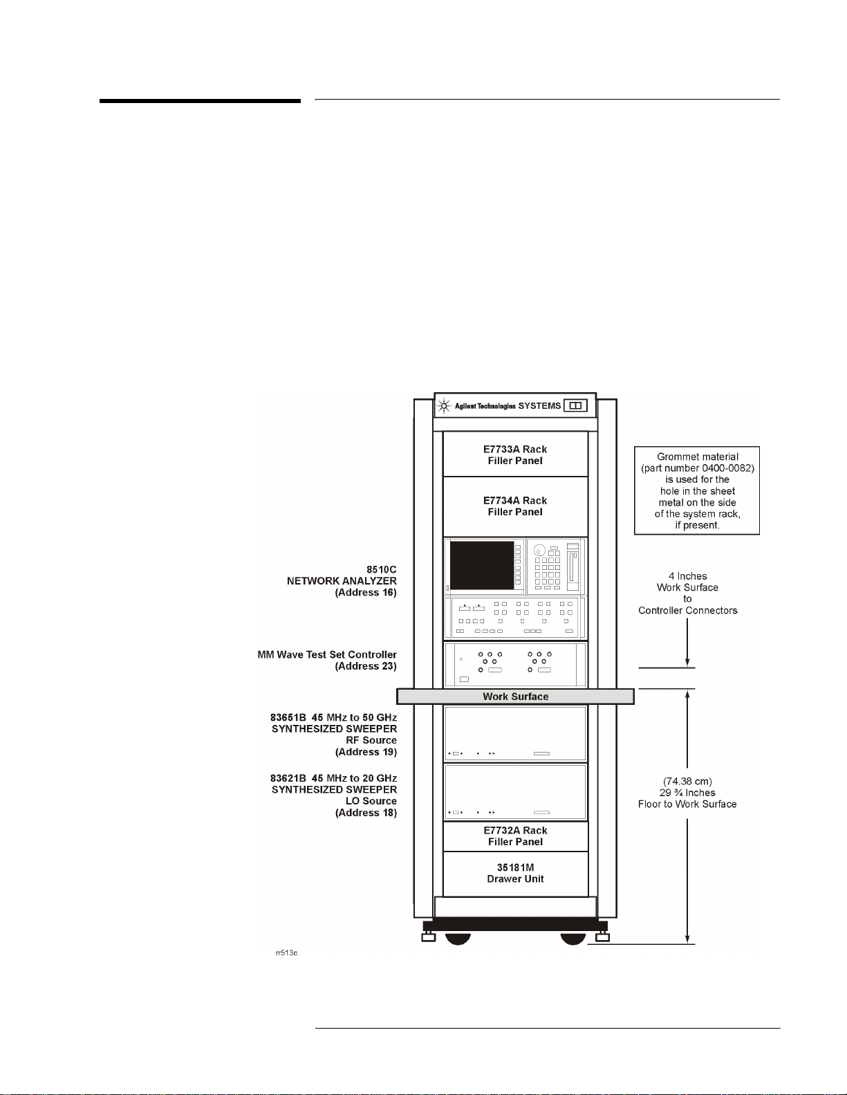
Coaxial Configuration When the 8510XF is configured for measurement through coaxial
connections, the network analyzer, millimeter wave controller, and RF and
LO sources are all installed in the system rack as show n in Figure 1. The t est
heads are placed on a work surface which is mounted below the millimeter
wave controller.
Figure 1 Network analyzer mounted in system rack
E7345A/E7355A - Installation Manual3
Page 13
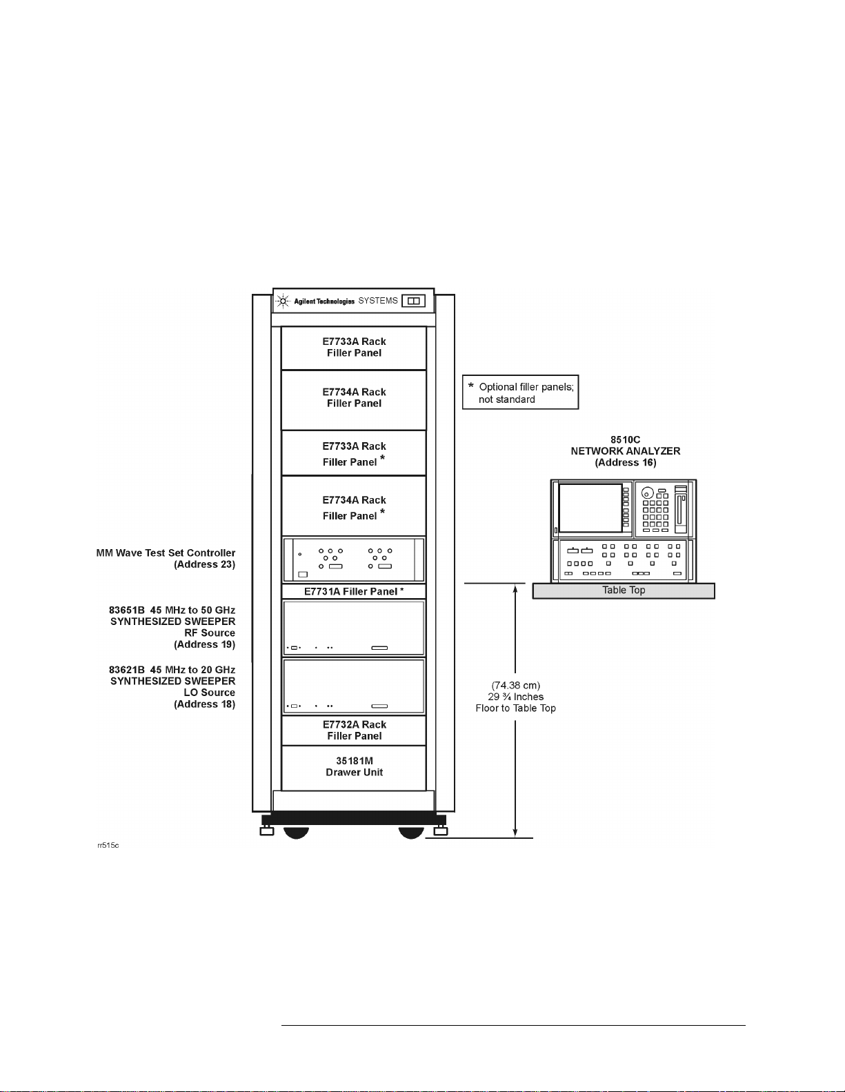
Wafer Probe
Configuration
When the 8510XF is configured for measurement through on-wafer probe
connections, the millimeter wave controller, and the RF and LO sources are
installed in the rack. However, the network analyzer and the wafer probe
station are placed side-by-side on a work surface in front of the test system,
as shown in Figure 2.
Figure 2 Network analyzer located on work surface
4E7345A/E7355A - Installation Manual
Page 14

Overview of the Upgrade Packages
The E7345A or E7355A upgrade packages will upgrade an
existing 85107B network analyzer system to the 8510XF system with
85 GHz or 110 GHz capability, respectively.
8510XF (85 GHz) Use the E7345A package to upgrade an 85107B to an 8510XF with 85 GHz
capability. With this packag e, you will do the following:
• Check the operation of 85107B.
• Check the memory in 8510C vector network analyzer.
• Upgrade the memory in the 8510C vector network analyzer.
• Disconnect unwanted elements from the existing system.
• Install an E7341A millimeter wave controller.
• Install an 83621B RF source.
• Install millimeter wave test set.
• Reconnect the system.
• Load the 8510XF operating system.
• Use the 8510C performance verification software to verify performance
of 8510XF in coax.
8510XF (110 GHz) Use the E7355A package to upgrade an 85107B to an 8510XF with
110 GHz capability. With this package, you will do th e following:
• Check the operation of 85107B.
• Check the memory in 8510C vector network analyzer.
• Upgrade the memory in the 8510C vector network analyzer.
• Disconnect unwanted elements from the existing system.
• Install an E7341A millimeter wave controller.
• Install an 83621B RF source.
• Install millimeter wave test set.
• Reconnect the system.
• Load the 8510XF operating system.
• Use the 8510C performance verification software to verify performance
of 8510XF in coax.
E7345A/E7355A - Installation Manual 5
Page 15

Installation Procedure Outline
Follow this outline to install either the E7345A or E7355A performance
upgrade. Detailed procedures are provided in the subsequent sections.
Step 1 Secure a Static Safe Work Station
Check for the following:
• the static mat sits on a clean, flat, sturdy surface.
• the static mat has a connection to an earth ground.
• the static mat has a wrist strap connected to it.
Step 2 Verify the Upgrade Package Contents
Using the packing list for your upgrade kit, check the completeness of
the package. If the kit does not have all the items listed, contact your
local Agilent Technologies office (see table inside the front of this
manual).
Step 3 Secure Items Not Included in Upgrade Package
Using the table p rovi ded in th is se ction, ob tain the items require d b ut not
supplied in the package.
Step 4 Check the 85107B System O peration and Memory
Using the instructions in this section, check that the system you plan to
upgrade functions.
Step 5 Install Non-Volatile Memory Upgrade (if needed)
Using the in structions in this section, install additional memory in the
8510C.
Step 6 Disconnect Unneeded Equipment
Using the instructions in this section, disconnect the equipment not
needed for the upgraded system and remove them from the system rack.
Step 7 Install the Millimeter Wave Controller
Using the instructions in this section, install the E7341A
millimeter wave controller.
6 E7345A/E7355A - Installation Manual
Page 16

Step 8 Install the 83621B RF Source
Using the instructions in this section, install the 83621B RF source.
Step 9 Reconnect the System
Using the instructions in this section, reconnect the system.
Step 10 Install the Millimeter Wave Test Set
Using the instructions in this section, install the millimeter wave test set.
Step 11 Load the 8510XF Operating System (Firmware)
Using the instruc ti ons i n this section, l oad the 8510XF operating system.
Step 12 Performance Check the Upgraded 8510XF System
Using the instructions in this section, performance check the upgraded
85107B system.
E7345A/E7355A - Installation Manual 7
Page 17

Step 1. Secure Static Safe Work Station
Static electricity builds up on the body and on tools, including calibration
components and devices under test. When static electricity is accidentally
discharged, sensitive circuit elements can be damaged.
CAUTION It is important that appropriate measures are taken to adequately discharge
static electricity which may otherwise damage test equipment circuitry.
Circuit elements wit hin a de vic e can be damaged fr om static e lectric ity, such
as through acciden tal contact with the center conductor of a connector. Even
a discharge that is too small to be felt can cause circuit damage.
Protection against electrostatic discharge (ESD) is essential while
connecting, cleaning, or inspecting connectors attached to static-sensitive
circuits, such as those found in test sets. Protective measures appropriate to
the 8510 series systems are described below.
• Always use a grounded anti-static mat in front of your test equipment,
and wear a grounded wrist strap attached to it.
• Ground yourself before you clean, inspect, or make a connection to a
static-sensitive device or test port. You can, for example, grasp the
grounded outer shell of the tes t port briefl y to disc harge static from your
body .
• Discharge static electricity from a device before connecting it, such as
by touching the device briefly through a resistor of at least 1 M
either the outer shell of the test port or to another exposed ground.
ESD Accessories The following accessories for preventing electrostatic discharge can be
ordered from Agilent Technologies:
Item Part Number
Grounding wrist strap 9300-1367
Grounding cord for wrist strap (5 ft) 9300-0980
Conductive table mat (2 x 4 ft)
with ground wire (15 ft)
ESD heel strap (for conductive floors) 9300-1126
9300-0797
Ω to
8 E7345A/E7355A - Installation Manual
Page 18

Step 2. Verify Upgrade Package Contents
Following are the content s of the E7345A and E7355A performanc e upgrade
packages. Compare this list against the packing list and against the actual
package contents. If the kit does not have all of the item s list ed, contact your
nearest Agilent Technologies office (refer to “Contacting Agilent” on
pagevi).
Table 1 Performance Upgrade Package Contents
Item Part Number
Software Data Disk 08510-10033 1 1
Cable, IF Interconnect 08510-60107 1 1
Cable, IF Interconnect 08510-60126 2 2
IC EEPROM, 32K X 8 (Memory Chips) 1818-7167 8 8
Adapter, 3.5mm (f-f) 5061-5311 1 1
Power Cable, 03C 03f-03m 8120-1348 2 2
Power Cable, 03C 03F-03M 8120-1405 1 1
Cable Assembly, BNC 8120-1838 1 1
Cable Assembly, BNC 8120-1839 1 1
Cable, GPIB 8120-3447 1 1
Cable Assembly, BNC 8120-5370 2 2
Synthesized Sweeper 83621B 1 1
Rack Flange Kit 83621B number 913 1 1
Adapter, 2.4mm (f-f) 85056-60006 1 1
E7345A
Quantity
E7355A
Quantity
8510XF Operating System E7340-10001 1 1
Semirigid Cable E7340-20075 1 1
Semirigid Cable E7340-20076 1 1
Cable, DC Bias E7340-60009 2 2
System Rack, 1.6 m, 120V E7340-60097 1 1
Service Quick Reference Guide E7340-90013 1 1
Millimeter Controller E7341A 1 1
Head Assembly, Left E7342L 1 0
Head Assembly, Right E7342R 1 0
LO Cable, 3.5mm-3.5mm E7342-60004 2 2
E7345A/E7355A - Installation Manual9
Page 19

Table 1 Performance Upgrade Package Contents (Continued)
Item Part Number
RF Cable, 2.4mm E7342-60005 4 4
Head Assembly, Left E7352L 0 1
Head Assembly, Right E7352R 0 1
System Manual E7350-90001 1 1
Upgrade Installation Manual E7350-90003 1 1
E7345A
Quantity
E7355A
Quantity
NOTE The table top is not included with the E7345A or the E7355A upgrade kit s. It
may be ordered from Agilent Technologies using part number 85106-60038
(refer to “Contacting Agilent” on pagevi).
10E7345A/E7355A - Installation Manual
Page 20

Step 3. Secure Additional Installation Equipment
Equipment Required But
Not Supplied
Table 2 Equipment Required But Not Supplied
The following additional equipment will aid in the installation of the
upgrade package, but are not included in the upgrade kit.
Make sure that these items are available and at hand before proceeding with
the upgrade.
Item Part Number
Network Analyzer 8510C
Source 83650B or 83651B
Test Set (optional) 8517B
Calibration/Verification kit 85059A
GPIB cables 10833A
BNC to BNC cable 10503A
Small Pozi-drive (#1) 8710-0899
Medium Pozi-drive (#2) 8710-0900
Flat blade screwdriver not supplied
Static control table mat 9300-0797
Wrist strap 9300-1367
Wrist-strap-to-mat cord (5 ft) 9300-0980
PC with BASIC for Windows (Rev. 6.3 or
higher)
not supplied
E7345A/E7355A - Installation Manual 11
Page 21

Step 4. Check the 85107B System Operation and
Memory
The followi ng info rmatio n appli es to both t he E7345A and E7355A upgr ade
kits. Use this procedure to ensure that the existing 85107B system works
properly before installing the upgrade package.
Procedure 1. Turn on the instruments in the following order:
a. the 83651B source (be sure to turn the switch to power on, not
standby)
b. the 8517B test set
c. the 8510C network analyzer
2. On the 85102, press the green preset key.
3. Does the system pass self-test (85101 self tests, 85102 running error
messages, and test set unratio of power tests) and display a
trace? If not, do not perform the upgrade until the system has been
serviced.
LOG MAG S
11
4. Initialize a blank disk, as follows:
a. load a blank diskette (with write-protect off),
b. on the 85102, press
c. on the 85101, select
5. Does the system initialize the disk and display
not, tag the 85101, indicating that it has a defective disk drive. The disk
drive must be working to load the 8510XF firmware.
NOTE Steps 6 and 7 below apply only to a CRT based display.
6. Turn the CRT to its highest intensity. Does the image remain focused? If
not, return the CRT to its normal intensity and tag the 85101, indicating
that it has a defective CRT.
7. Return the CRT to its normal intensity. As long as the CRT functions
properly, continue with this procedure.
DISK,
INITIALIZE DISK: YES.
DISK INITIALIZED? If
12 E7345A/E7355A - Installation Manual
Page 22

8. If the system displays a self-test,* running error message, or unratio
power test failure, check the equipment setup. Do not perform the
upgrade until either you correct the setup problem, or you have the
system serviced.
* You may have to rely on the red LEDs rather than the display.
E7345A/E7355A - Installation Manual 13
Page 23

Step 5. Install Non-Volatile Memory Upgrade
(if needed)
The 8510XF firmware requires at least 832 Kbytes of non-volatile memory.
To determine how much
memory is installed in the
system
CAUTION Incorrect useage of the password can erase the non-volatile memory.
To increase the
non-volatile memory
1. With the 85107B system on, press [SYSTEM] {More} {Service Functions} {Test
Menu}.
2. Select
3. Select
4. Select
5. A password is required, which is “8515”.
6. Select
1. Place the 8510C on an ESD safe work surface and insure t here is no AC
2. Remove the two plastic feet on the rear upper portion of the 8510C, and
22: run service program.
1: 85101 Display/processor service program.
4: non-volatile memory board.
8. If the Number of Pages reading is equal to or greater than
30BB, there is enough memory for running the 8510XF firmware. Skip
the balance of this procedure and go to “Step 6. Disconnect Unneeded
Equipment” on page17.
power connected to the rear panel.
then remove the top cover. The PC boards are located beneath the metal
cover that runs the length of the right side of the chassis.
3. Remove the 21 screws that secure the cover and remove the cover to
access the PC boards. The board that contains the non-volatile memory
is the A6 board, and is easily identified by its orange card extractor.
4. Remove the plastic card spacers that position the A6 board.
5. Gently grab the card extractor tabs on the ends of the board, and pull
away and up to remove the board.
6. Place the board on an ESD safe work surface. There ar e 16 ba nks on the
board, and 8510XF requires at least 13 banks. There are 8 IC chips
supplied with this kit. Fill the empty slots until at least 13 banks are
filled. The ICs to be loaded in these sockets are a CMOS version of the
original replacement IC (part number 1818-4653).
14E7345A/E7355A - Installation Manual
Page 24

7. Carefully bend the leads of the IC chips so that the leads are
perpendicular to the body and insert them into the empty sockets. Be
sure to match up the notch on the top of the chips with the notch on the
sockets. Gently press them into place making su re that all le ads go into
the socket.
8. After the ICs have been installed, gently insert the A6 board back into its
connector.
Verify the memory
upgrade with chassis open
9. Plug the power cord into the 85101C, turn on the power, and allow the
instrument to complete its initialization.
10. With the 85101C box on, press
11. Select
12. Select
13. Select
22: run service program.
1: 85101 Display/processor service program.
4: non-volatile memory board.
[=marker] to enter the Test menu.
14. A password is required, which is “8515”.
CAUTION Incorrect useage of the password can erase the non-volatile memory.
15. Select
16. On the front panel of the 8510C, select
1:Initialize Memory.
Prior Menu, then Show Non-Volatile
Memory Parameters. The 8510C should be displaying the memory board
parameters. If the EEPROM in the highest memory page was read
successfully, then the # of pages should read at least
30BB. Ignore the
present position information. The number-of-pages information is only
useful for indicating whether the last bank of upgraded memory is good
or not.
Memory Write/Read Test 17. To determine if all of the added memory banks are functioning, select
Prior Menu, then
18. Press
[=Marker] [x1]. This test takes a few minutes to run. If all the memory
banks are working, the display will read that the first useable memory
bank location is
following chart to determine which EEPROM chip is at fault.
Complete Memory Board Unformatted Write/Read Test (2).
10 hex. If any other hex location is listed, refer to the
E7345A/E7355A - Installation Manual 15
Page 25

First Unuseable Memory
Location Read
0C Hex U13 or U29
0D Hex U14 or U30
0E Hex U15 or U31
0F Hex U16 or U32
Possible Fault Location
Try replacing one or the other or both of the EEPROMS listed if you do
not get 10 Hex as the first useable memory location. Continue repeating
the above test until the bad EEPROM(s) are identified.
19. When the EEPROMs are found to be working properly, turn off the
8510C and remove the power cord from the rear panel.
20. Reinstall the plastic spacers on the A6 board.
21. Place the cover over the PC board cage and secure the original 21
screws.
22. Install the top cover on the 8510C and finish integrating the
8510C into the system depending on the configuration.
16 E7345A/E7355A - Installation Manual
Page 26

Step 6. Disconnect Unneeded Equipment
If upgrading to an 8510XF with Option 006, the 8517B test set must have
Option 001, multi-test set compatibility. If 8517B does not have Option 001
installed, you will need to order and install this upgrade kit (p/n
08510-60008).
If this is the case, the 8517B will need to b e relocated to facilitate the
millimeter wave controller. The 8517B should be removed from the rack and
placed on the work surface or another rack. The 8517B should be placed as
close to the millimeter wave controller as possible.
If the 8510XF does not include Option 006, the n remov e the 8517 B from the
test system prior to installing the upgrade.
E7345A/E7355A - Installation Manual 17
Page 27

Step 7. Install the Millimeter Wave Controller
Install the 7341A millimeter wave controller into the system rack as shown
in Figure1 on page3 (in-rack configuration) or Figure2 on page4
(table-top configuration).
18E7345A/E7355A - Installation Manual
Page 28

Step 8. Install the 83621B RF Source
Install the second source into the system rack as shown in Figure 1 (in-rack
configuration) or Figure 2 (table-top configuration).
E7345A/E7355A - Installation Manual19
Page 29
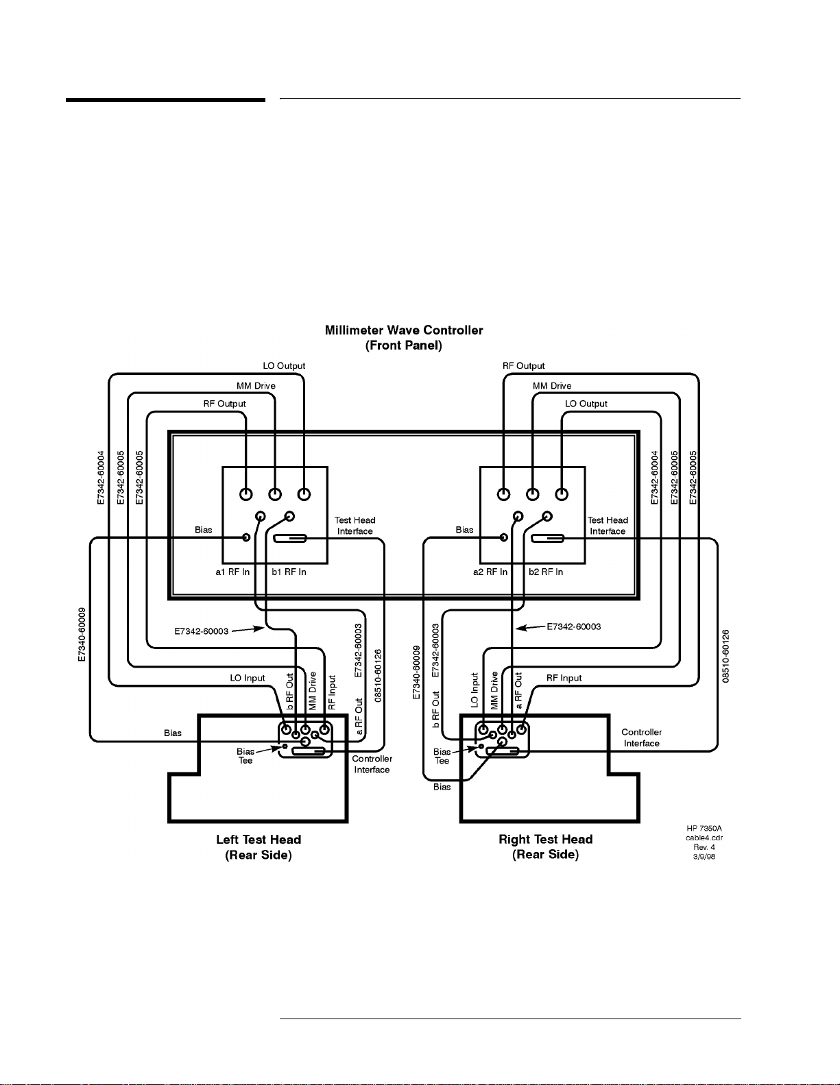
Step 9. Install the Millimeter Wave Test Set
Using the following procedure, install the millimeter wave test set:
1. Place the test heads on the table top or work surface in front of the
millimeter wave controller.
2. Connect the cables as shown in Figure 3. Installat ion of these cables may
require a long, 5/16-inch open-ended wrench.
Figure 3 Controller to Test Heads Cabling
20E7345A/E7355A - Installation Manual
Page 30
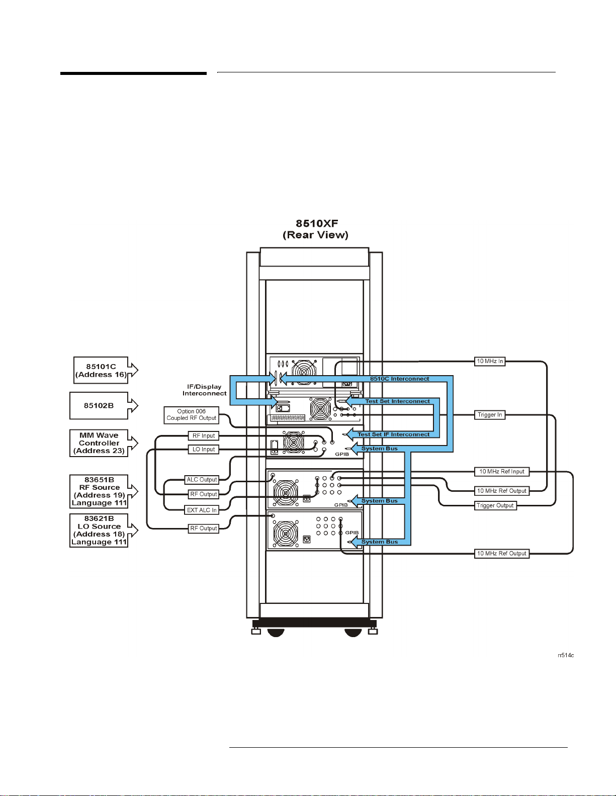
Step 10. Reconnect the System
Reconnect the test system according to the desired configuration. Figure 4 shows the
system wiring for the coaxial configuration. Figure5 on page22 shows the system
wiring for the on-wafer configuration.
Figure 4 Coaxial configuration system cabling diagram
E7345A/E7355A - Installation Manual21
Page 31
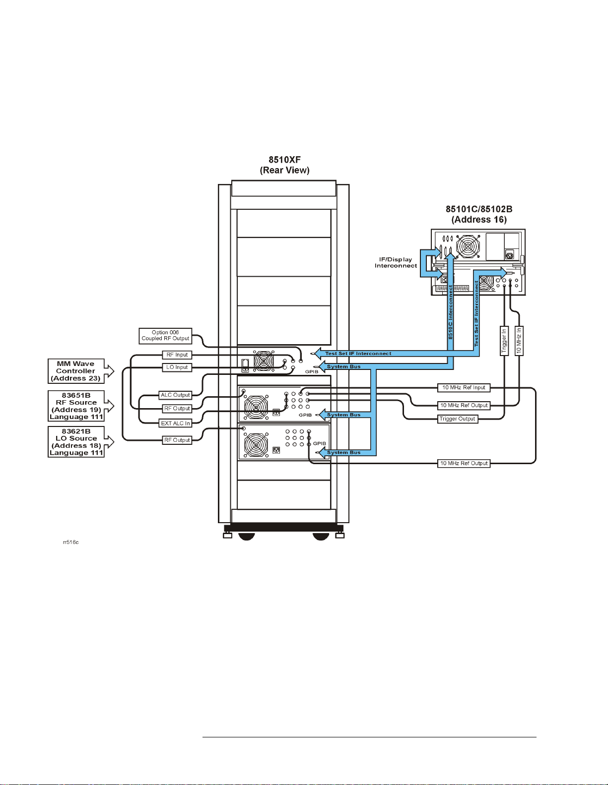
Figure 5 On-wafer configuration system cabling diagram
22 E7345A/E7355A - Installation Manual
Page 32

Step 11. Load 8510XF Operating System (Firmware)
Step 11. Load 8510XF Operating System
(Firmware)
Perform the following procedure to load the 8510XF software.
1. Insert the operating system disk into the 85101 disk drive.
Introduction
2. On the 8510C, press
3. Select
{Test Menu}, and then 19. It takes about 3 minutes to load the
software and reinitialize the system.
[SYSTEM] {More}, and then select {Service Function}.
E7345A/E7355A - Installation Manual 23
Page 33

Introduction
Step 12. Perform the 8510XF Performance Verification
Step 12. Perform the 8510XF Performance
Verification
Refer to the 8510XF System Manual for the procedures to perform a
Performance Verification on the upgraded system.
24 E7345A/E7355A - Installation Manual
 Loading...