

Page 1

HP 8509A/B LightwavePolarization Analyzer
Programming Guide
ABCDE
08509-90017
No.
Part
HP
Printed
in
USA
October
1994
Page 2

Notice.
The information contained in this do cument is sub ject to change without notice.
Hewlett-Packard makes no warrantyofany kind with regard to this material, including
but not limited to, the implied warranties of merchantability and tness for a particular
purpose. Hewlett-Packard shall not be liable for errors contained herein or for incidental or
consequential damages in connection with the furnishing, performance, or use of this material.
Windows and QuickBasic are trademarks of Microsoft Corporation.
c
Cop
All Righ
ermission
p
oun
F
1400
yrigh
ts
taingro
Hewlett-P
t
Reserv
prohibited,
is
v
ed.
e
Repro
arkw
P
kard
ac
except
a
Compan
duction,
as
Santa
,
y
1994
y
adaptation,
under
ed
w
allo
CA
Rosa,
translation
or
cop
the
95403-1799,
yrigh
USA
without
ws.
la
t
prior
written
Page 3

Certification
Hewlett-Packard Company certies that this pro duct met its published specications at the
time of shipment from the factory. Hewlett-Packard further certies that its calibration
measurements are traceable to the United States National Institute of Standards and
Technology, to the extent allo wed by the Institute's calibration facility, and to the calibration
facilities of other International Standards Organization members.
Warranty
This Hewlett-Packard instrument pro duct is warranted against defects in material and
workmanship for a perio d of one year from date of shipment. During the warranty period,
Hewlett-Packard Company will, at its option, either repair or replace products whichproveto
be defective.
For warranty service or repair, this pro duct must be returned to a service facility designated
and
ard
k
Buy
to
by
when
to
ac
w
Ho
er.
Hewlett-P
Hewlett-Pac
erly installed
prop
instrumen
the
of
ev
er,
ac
k
Buy
ard
k
ard
er
for
on
or
t,
Hewlett-P
y
b
Hewlett-P
pay
shall
another
from
Hewlett-P
with
use
instrumen
that
are,
w
soft
ac
kard
ac
shipping
all
coun
ard
k
ac
instrumen
an
rm
or
ard.
k
shall pa
try
arran
w
Hewlett-P
t.
are
w
er
Buy
y shipping
harges,
c
.
ts
will
t
b
will
shall
duties,
that
execute
kard
ac
unin
e
prepa
charges
soft
its
its
es
do
terrupted
shipping
y
return
to
taxes
and
and
are
w
programming
arran
w
not
error-free.
or
c
for
rm
harges
pro
w
that
t
Hewlett-P
to
duct
pro
the
returned
ducts
designated
are
instructions
op
the
eration
Limita
tion
foregoing w
The
tenance
main
misuse,
preparation
site
eration
op
y
b
arrant
Buy
outside
or
not
shall
y
er-supplied
Buy
er,
the
of
maintenance.
apply
vironmen
en
to
soft
defects
are
w
sp
tal
resulting
terfacing,
in
or
from
ecications for
improp
er
unauthorized
the pro
duct, or
inadequate
or
dication
mo
improper
arranty
W
of
NO OTHER WARRANTY IS EXPRESSED OR IMPLIED. HEWLETT-PACKARD
SPECIFICALLY DISCLAIMS THE IMPLIED WARRANTIES OF MERCHANTABILITY
AND FITNESS FOR A PARTICULAR PURPOSE.
Exclusive Remedies
CLUSIVE
EX
THE REMEDIES
REMEDIES.
HEWLETT-P
PR
VIDED
O
HEREIN
CKARD
A
INDIRECT, SPECIAL, INCIDENT
BASED ON CONTRA
CT, TOR
T, OR
ARE
SHALL
BUYER'S
NOT
SOLE
BE LIABLE
AL, OR CONSEQUENTIAL D
ANY OTHER LEGAL THEOR
AND
DIRECT,
ANY
OR
F
AMAGES, WHETHER
Y.
or
iii
Page 4

Safety Notes
The following safety notes are used throughout this manual. Familiarize yourself with eachof
the notes and its meaning before operating this instrument.
Caution
Caution denotes a hazard. It calls attention to a pro cedure that, if not
correctly p erformed or adhered to, would result in damage to or destruction
of the instrument. Do not proceed b eyond a caution sign until the indicated
conditions are fully understood and met.
Warning
Warning denotes a hazard. It calls attention to a procedure which, if not
correctly performed or adhered to, could result in injury or loss of life. Do
not proceed beyond a warning note until the indicated conditions are fully
understood and met.
L
The instruction documentation symbol. The pro duct is marked with this symbol when
it is necessary for the user to refer to the instructions in the do cumentation.
The
\CE"
year,
ya
b
\ISM1-A"
\CSA"
The
CE
it is
This
CSA
is
mark
when the
sym
a
is
mark
registered
a
design
of an
bol
registered
a
is
trademark
pro
as
w
Industrial
trademark
v
en.)
of the
Scien
European
Medical
and
tic
the Canadian
of
Communit
Group
Standards
y.
1
accompanied
(If
A
Class
ciation.
Asso
pro
duct.
iv
Page 5

General Safety Considerations
Warning
Warning
Caution
This is a Safety Class I product (provided with a protective earthing ground
incorporated in the power cord). The mains plug shall only be inserted in a
socket outlet provided with a protective earth contact. Any interruption of the
protective conductor, inside or outside the instrument, is likely to make the
instrument dangerous. Intentional interruption is prohibited.
No operator serviceable parts inside. Refer servicing to qualified personnel. To
prevent electrical shock, do not removecovers.
Before switching on this instrument, make sure that the line voltage selector
switch is set to the voltage of the power supply and the correct fuse is
installed.
v
Page 6

How to Use This Guide
This guide uses the following conventions:
4
Front-Panel Key
NNNNNNNNNNNNNNNNNNNNNNN
Softkey
Screen Text
This represents a key physically located on the instrument.
5
This indicates a \softkey," a key whose label is determined bythe
instrument's rmware.
This indicates text displayed on the instrument's screen.
vi
Page 7

Contents
1. Introduction
2. Starting Up the System For HP-IB Control
3. HP-IB Overview
Bus Structure . . . . . . . . . . . . . . . . . . . . . . . . . . . . 3-1
Data Bus . . . . . . . . . . . . . . . . . . . . . . . . . . . . . 3-1
Handshake Lines . . . . . . . . . . . . . . . . . . . . . . . . . . 3-2
Control Lines . . . . . . . . . . . . . . . . . . . . . . . . . . . . 3-2
Sending Commands . . . . . . . . . . . . . . . . . . . . . . . . . . 3-3
8509
HP
the
4. HP-IB
HP-IB
`Command
For
.
.
.
.
Options
. .
executable
of
Num
<
rame
F
.
.
.
.
.
.
.
.
.
.
.
.
.
.
.
. .
.
.
.
.
.
.
.
>
Min
of
er
b
. .
.
.
.
.
.
.
.
.
.
.
.
.
.
.
.
. .
.
.
.
.
.
.
.
.
terface
In
DDE
to
Setup
Line'
Name
<
Con
.
troller
. .
trol
.
.
.
.
.
.
State .
.
/Errors
/HP8509=
/HP8509TimeOut=
HP
HP-IB
Dynamic Data Exchange (DDE) Frame . . . . . . . . . . . . . . . . 4-6
Only
8509
Frame
Separator
Data
Cr/Lf
Comma
HP-IB Exit
Con
Non-Controller . . . . . . . . . . . . . . . . . . . . . . . . . 4-6
.
.
.
.
.
.
.
.
.
.
.
.
.
.
.
utes
.
.
.
. .
.
.
.
.
.
.
.
.
.
.
.
.
. .
. .
.
.
.
.
.
.
.
.
.
.
.
.
.
.
.
.
. .
. .
.
. 4-3
. .
.
.
.
.
.
.
.
.
.
.
.
.
.
.
.
. .
.
.
.
.
.
.
.
.
.
.
.
.
.
.
.
.
.
.
.
.
.
. .
.
.
.
.
.
.
>
.
.
.
.
.
.
.
.
.
.
.
.
.
.
.
.
.
.
.
.
. .
.
.
.
.
.
.
.
.
.
.
.
.
.
.
.
.
.
.
.
. .
.
.
.
.
.
.
.
.
.
.
.
.
.
.
.
.
.
.
.
.
.
.
. .
.
.
.
.
.
.
.
.
.
.
.
.
.
.
.
.
.
. .
. .
. .
.
.
.
.
.
.
.
.
.
.
.
.
.
.
.
.
.
.
. .
. .
. .
. .
.
.
4-2
4-3
4-3
4-3
4-4
4-5
4-5
4-5
4-5
4-5
4-6
5. Basic Instrument Control
Data Requesting Commands . . . . . . . . . . . . . . . . . . . . . . 5-3
.
.
.
. .
.
.
.
.
.
.
.
.
.
.
.
. .
.
.
.
.
.
.
eration
Op
Preparing
6. Interacting with the HP
Establishing DDE Links
Sending HP 8509 Commands via DDE .
Retrieving HP 8509 Data via DDE
Complete
HP-IB Con
or
F
.
.
.
.
.
.
.
.
.
.
trol
8509A/B Through the DDE
. . . . . . . . . . . . . . . .
. . . . . . . . . . . . . . . . . 6-4
. . . .
. . . . . . . . . . . . . . . 6-5
.
.
.
.
.
.
.
.
.
. .
.
. . . . . . . . 6-1
Contents-1
.
.
5-4
5-5
Page 8
7. Measurement Programming
Calibrate the Instrument. . . . . . . . . . . . . . . . . . . . . . . . 7-2
Set Up the Instrument. . . . . . . . . . . . . . . . . . . . . . . . . 7-2
Connect the Device . . . . . . . . . . . . . . . . . . . . . . . . . . 7-2
Take Data . . . . . . . . . . . . . . . . . . . . . . . . . . . . . . 7-2
Transfer Data . . . . . . . . . . . . . . . . . . . . . . . . . . . . 7-2
8. Remote Command Reference
Command Syntax . . . . . . . . . . . . . . . . . . . . . . . . . . . 8-1
Abbreviations / Denitions . . . . . . . . . . . . . . . . . . . . . . . 8-4
Changes from Version 1.2 Software . . . . . . . . . . . . . . . . . . . 8-5
*OPC[?]
Cal:Calibrate
Disper:Close
Source? Source:External? Source:Internal?
Common Commands . . . . . . . . . . . . . . . . . . . . . . . . . 8-6
*IDN?
*OPC[?]
Device
Analog?
Analog:Done
Analog:{
Angles:{
Angles:{
Angles:Done
Angles:{
Average:Display:{
Average:Display{
Average:Done
Average:Measure{
Cal?
Cal:Calibrate
Cal:{
Cal:Delete:<Wavelength nm>
Cal:List?
Cal:{ Off | On }
ClearParams
DBase:Close
DBase:Compact
DBase:Filename?
DBase:Open:<"filename">
DBase:Repair
Disper
Disper?
Disper:ActiveWindow?
Disper:Atten{ ? | :<dBm value> }
Disper:Calibrate
Disper:{
Disper:Chain[?]
Disper:Clear
Disper:Close
. . . . . . . . . . . . . . . . . . . . . . . . . . . . . . 8-5
. . . . . . . . . . . . . . . . . . . . . . . . . . . 8-5
. . . . . . . . . . . . . . . . . . . . . . . . . . . 8-5
. . . . . . . . . . . . 8-5
. . . . . . . . . . . . . . . . . . . . . . . . . . . . . . . 8-6
. . . . . . . . . . . . . . . . . . . . . . . . . . . . . . 8-6
.
.
.
.
.
. .
. .
. .
.
.
.
.
.
.
.
.
.
.
Commands
ecic
Sp
.
.
.
.
.
. .
Raw
|
Off
AC?
|
AB?
Degrees
Off
.
.
.
|
Done
. . . . . . . . . . . . . . . . . . . . . . . . . . . . . 8-8
. . . . . . . . . . .
. . . . . . . . . . . . . . . . . . . . . . .
Cascade
|
. .
.
On
|
. .
.
.
.
.
.
Save
. . . . . . . . . . . . . . . . . . . . . . . . . . 8-8
. . . . . . . . . . . . . . . . . . . . . . . . . . . . 8-9
. .
.
.
.
.
.
. . . . . . . . . . . . . . . . . . . . . . .
|
.
.
.
.
.
.
.
.
.
.
.
.
.
.
.
.
.
.
.
.
. .
. .
. .
. .
.
.
. .
.
.
.
.
.
.
.
.
.
.
.
.
.
.
.
.
.
. .
. .
. .
. .
. .
.
.
.
.
.
.
.
.
.
.
.
.
.
[?]
Stokes
|
BC?
|
Radians
.
.
.
}
Off
:<NumPoints>
|
?
.
.
:<NumPoints>
|
?
.
.
.
.
}
.
.
.
.
. .
. . . . . . . . . . . . . . . . . . . . . . . . . 8-10
Single }[?]
.
.
.
.
.
.
}
.
.
.
.
.
.
.
.
.
. .
. .
.
.
.
.
.
.
.
}
.
.
.
.
.
.
.
.
.
.
.
. .
.
.
.
}[?]
.
.
.
.
.
.
}
On
|
.
.
.
.
.
.
.
.
.
. .
. .
.
.
.
.
.
.
.
.
.
. . . . . . . . . .
. . . . . . . . . . . . . . . . . . . . . . . 8-10
.
.
.
.
.
.
.
.
.
.
. .
.
.
.
.
.
.
.
.
.
.
.
.
.
.
.
.
.
.
.
.
.
.
.
.
. .
.
.
.
.
.
.
.
.
.
.
.
.
.
.
.
.
.
.
.
.
. .
.
.
.
.
.
.
.
.
.
.
.
.
.
.
.
.
.
.
.
.
. .
.
}
. .
. .
.
.
.
.
.
.
.
.
.
.
.
.
.
.
.
.
. .
. .
.
.
.
.
.
.
.
.
.
.
.
.
}
.
.
.
.
.
.
.
. .
. .
. .
. .
.
.
.
.
.
.
.
.
.
.
.
.
.
.
. .
. .
. .
. .
.
.
.
.
.
.
.
.
.
.
.
.
.
.
.
.
.
.
.
. . . . . . . . . . . . . . . . . . . . 8-8
.
.
.
.
.
.
.
.
.
.
.
. .
.
.
.
.
.
.
.
.
.
.
. .
.
.
.
.
.
.
.
.
.
.
.
. .
.
.
.
.
.
.
.
.
.
.
. .
.
.
.
.
.
.
.
. . . . . . . . . . . 8-9
. . . . 8-9
. . . . . . . . . . . . . . . . . . . 8-9
. . . . . . . 8-10
. . . . . . . . . . . . . . . . . . 8-10
.
.
.
.
.
.
.
.
.
.
.
.
.
.
.
.
.
.
.
.
.
. .
.
.
.
.
.
.
.
.
.
.
.
.
.
.
.
.
.
.
.
.
.
.
.
.
. .
.
.
.
.
.
.
.
.
.
.
.
.
.
.
.
.
.
.
.
.
.
.
.
.
. .
.
.
.
.
.
.
.
.
.
.
.
. 8-9
.
.
.
.
.
.
8-6
8-6
8-6
8-6
8-7
8-7
8-7
8-7
8-7
8-7
8-7
8-8
8-8
8-8
8-8
8-9
8-9
8-11
8-11
8-11
8-11
Contents-2
Page 9
Disper:DBase:Load:<"title">
Disper:DBase:Save:<"title"> [ :<"date code"> [ :<"serial number"> ]]
Disper:Done
Disper:FiberLen{ ? | :<km> }
Disper:FindMinPoints[:<Num Samples>]
Disper:HPIB[?]
Disper:Manual
Disper:Manual?
Disper:Measure
Disper:NewThruCal
Disper:Power?
Disper:Power:{ dBm | uWatt }[:<value>]
Disper:Restart
Disper:Save:<"filename">
Disper:Settle:{ Point | Start }{ ? | :<Delay msec>}
Disper:Start
Disper:Trace:<"filename">
Disper:Units{ ? | :ps | :ps/L | :ps/sqrtL | :fs | :fs/L | :fs/sqrtL }
Disper:VTune[?]
Disper:VTune:{
Disper:WLen?
Disper:WLen:Points{
Disper:WLen:{
Disper:WLen:Steps{
Display:Angles:{
Display:Angles:{
Display:Power:{
Display:Update{
Drive?
Drive:<MS-DOS
GetFile:<"filename">
GetMarker:{ A
GetMarker?:{A|B|C}
Jones?
Jones:{ Absolute | Relative }[?]
Jones:Calibrate[A | B | C]
Jones:Clear
Jones:Done
Jones:{
Jones:{
Jones:Measure[A|B|C]
Jones:NewThruCal
Jones:ReStart
Load:Config:Preset
Load:Config:<"filename">
Load:Single:<"filename">
OperVer[?]
OperVer:{
PdlMaxMin[?]
PdlMaxMin:{ Max
PdlMaxMin:Delta?
. . . . . . . . . . . . . . . . . . . . . . . . . . . . 8-12
. . . . . . . . . . . . . . . . . . . . . . . . . . 8-13
. . . . . . . . . . . . . . . . . . . . . . . . . . . 8-13
. . . . . . . . . . . . . . . . . . . . . . . . . . 8-13
. . . . . . . . . . . . . . . . . . . . . . . . . . 8-13
. . . . . . . . . . . . . . . . . . . . . . . . . 8-14
. . . . . . . . . . . . . . . . . . . . . . . . . . . 8-14
. . . . . . . . . . . . . . . . . . . . . . . . . . 8-14
. . . . . . . . . . . . . . . . . . . . . . . . . . . 8-15
. .
. .
.
Stop
Start
.
Start |
.
.
.
.
Drive
B
|
. . . . . . . . . . . . . . . . . . . . . . . . . . . . . . 8-20
. . . . . . . . . . . . . . . . . . . . . . . . . . . . 8-20
.
.
External
MagRadians
. . . . . .
.
.
Start
.
|
.
.
.
.
.
:<NumPoints>
|
?
Stop
:<NumPoints>
|
?
On
|
Off
Degrees
Log
Linear
?
.
|
.
|
.
Cancel
|
.
Min
|
|
:<NumPoints>
|
. .
.
.
.
Spec>
.
.
.
.
}
C
. . . . . . . . . . . . . . . . . . . . . . 8-19
.
.
.
.
Internal
MagDegrees
|
.
. . . . . . . . . . . . . . . . . .
. . . . . . . . . . . . . . . . . .
.
.
.
.
|
. .
.
.
.
.
}
.
.
.
.
. . . . . . . . . . . . . . . . . . . 8-11
. . . . . . . . . . . . . . . . . . . . 8-12
. . . . . . . . . . . . . . . 8-12
. . . . . . . . . . . . . . 8-14
. . . . . . . . . . . . . . . . . . . . . 8-15
. . . . . . . . 8-15
. . . . . . . . . . . . . . . . . . . . 8-16
. .
.
.
.
.
.
.
.
.
.
.
.
.
.
.
.
.
.
.
.
. 8-16
.
.
.
.
.
.
.
.
.
:<Voltage>
|
?
}{
. .
.
.
.
.
.
.
}
|
?
.
.
}
.
.
.
.
.
.
.
}{
.
}
.
.
.
.
. .
}
.
.
.
.
.
.
}
.
.
.
.
.
.
.
.
.
.
.
.
.
.
.
.
. . . . . . . . . . . . . . . . . 8-20
. .
.
.
. .
.
RealImag
|
.
.
.
.
.
.
.
}
.
.
.
.
.
.
.
.
.
.
.
.
Delta
|
.
}
Radians
|
. .
. .
.
.
.
.
.
. . . . . . . . . . . . . . . . . . . . . 8-20
.
.
}[?]
. . . . . . . . . . . . . . . . . . . . . 8-21
. . . . . . . . . . . . . . . . . . . . . 8-22
. . . . . . . . . . . . . . . . . . . . . 8-22
. . . . . . . . . . . . . . . . . . . . . 8-22
.
.
Done
.
.
.
.
.
}
.
.
.
. .
.
. .
. .
.
:<Wavelength
.
.
.
.
.
.
.
.
.
. .
.
.
.
.
.
.
.
.
.
.
.
.
.
.
.
.
.
.
.
.
.
.
.
.
.
.
.
.
.
.
.
.
.
.
.
.
. .
. .
.
.
.
.
.
.
.
.
.
.
.
.
.
.
.
.
.
. .
.
.
.
.
. .
.
.
.
.
.
.
.
.
.
.
.
.
.
.
.
.
.
.
}[?]
.
.
.
.
.
.
.
.
.
.
.
.
.
.
.
.
.
.
.
.
.
.
.
.
nm>}
.
.
.
.
.
.
.
.
.
.
.
.
.
.
.
.
. .
.
.
.
.
.
.
. . . . . . . 8-22
.
.
.
.
.
.
.
. .
.
. 8-18
.
.
.
.
.
.
.
.
.
.
.
.
.
.
.
.
.
. 8-18
.
.
.
.
.
.
.
.
. .
.
.
.
.
.
.
.
.
.
.
.
.
.
. .
. .
. .
.
.
.
. .
.
.
. .
.
.
.
.
. .
.
.
.
.
.
. .
.
. . . . . . 8-22
.
.
.
.
.
.
.
.
.
.
.
.
.
.
.
.
.
.
. .
.
.
.
.
.
.
.
.
.
.
8-12
8-16
8-16
8-16
8-17
8-17
8-18
8-18
8-19
8-19
8-19
8-19
8-19
8-21
8-21
8-21
8-23
8-23
8-23
8-23
8-23
Contents-3
Page 10
PdlMaxMin:{ Reset | Clear | Done }
Poincare:Center:{ Stokes | A | B | C }
Poincare:Clear
Poincare:Hold:{ Off | On }
Poincare:Marker:{ A | B | C }
Poincare:Marker:Clear
Polarizer:{A|B|C|None}[?]
Polarizer:Angle{ A | B | C }{ ? | :<Degree Value> }
Polarizer:Done
Polarizer:{ External | Internal }
PolDep?
PolDep:{ Absolute | Relative }[?]
PolDep:Calibrate[A |B|C]
PolDep:Clear
PolDep:Done
PolDep:{ Internal | External }[?]
PolDep:{ JonesData? | PolDepData? }
PolDep:{ JonesMode | PolDepMode }[?]
PolDep:{ MagRadians
PolDep:Measure[A
PolDep:NewThruCal
PolDep:ReStart
PolMarker:{
PolMarker?:{
Range:Auto{
Range:{
Range{
RawDat?
RefFrame?
RefFrame:{
RefFrame:{
Save:Config:<"filename">
Save:Disper:<"filename">
Save:Jones:<"filename">
Save:PolDep:<"filename">
Save:Single:<"filename">
SerialNum?
SetMarker:<S0>:<s1>:<s2>:<s3>:{ A
Single
Single:Done
Single:DBase:Load:<"title">
Single:DBase:Save:<"title"> [ :<"date code"> [ :<"serial number">]]
Single:Freq{ ? | :<Hertz> }
Single:Mode{ ? | :Single | :Timed | :FreeRun }
Single:Period{ ? | :<Seconds> }
Single:Points{ ? | :<NumPoints> }
Single:Start
Source?
Source:External?
Source:External:{ Off
Source:External:<Wavelength
. . . . . . . . . . . . . . . . . . . . . . . . . . . . . . 8-25
Done
:<GainValue>
|
?
.
.
.
.
.
.
.
. . . . . . . . . . . . . . . . . . . . . . . . . . 8-24
. . . . . . . . . . . . . . . . . . . . . 8-24
. . . . . . . . . . . . . . . . . . . . . . 8-24
. . . . . . . . . . . . . . . . . . . . . . . . . . 8-24
. . . . . . . . . . . . . . . . . . . . 8-25
. . . . . . . . . . . . . . . . . . . . . . . . . . . 8-25
. . . . . . . . . . . . . . . . . . . . . . . . . . . . 8-26
| MagDegrees
.
.
C]
|
B
|
.
.
.
.
.
.
. .
.
.
.
.
.
.
.
.
.
}
C
|
B
A|
.
.
.
}
C
|
B
|
A
.
}
:On
|
:Off
|
?
.
Up }
|
Down
|
.
.
.
.
.
.
.
.
.
.
}[?]
|On
Off
}[?]
3pt
|
2pt
. . . . . . . . . . . . . . . . . . . . . . . . . . . . 8-31
. .
.
.
.
.
.
.
.
.
.
.
.
.
.
.
.
.
.
.
.
.
.
.
}
.
.
.
.
. .
.
.
.
.
.
.
.
.
.
. . . . . . . . . . . . . . . . . . . . . 8-30
. . . . . . . . . . . . . . . . . . . . . 8-30
. . . . . . . . . . . . . . . . . . . . . 8-30
. . . . . . . . . . . . . . . . . . . . . 8-31
.
.
.
.
.
.
.
.
. .
.
.
.
.
.
.
.
.
. .
.
.
.
.
}
On
|
nm>
. . . . . . . . . . . . . . . . . 8-23
. . . . . . . . . . . . . . . 8-23
. . . . . . . . . . . . . . . . . . . 8-24
. . . . . . . . . . . . . . . . . 8-24
. . . . . . . . . 8-24
. . . . . . . . . . . . . . . . . 8-25
. . . . . . . . . . . . . . . . . 8-25
. . . . . . . . . . . . . . . . . 8-26
. . . . . . . . . . . . . . . . 8-26
. . . . . . . . . . . . . . . 8-26
.
.
.
.
.
.
.
| RealImag
.
.
.
.
.
.
.
.
.
.
. .
.
.
.
.
.
.
.
.
.
.
.
.
.
.
.
.
.
.
.
.
.
.
.
.
.
.
. .
.
.
.
.
.
.
.
.
.
.
.
.
|
B
|
.
.
.
.
. .
.
.
. . . . .
. . . . . . . . . . . . . . . . . . 8-32
. . . . . . . . . . . . . . . . . . 8-32
. . . . . . . . . . . . . . . . . 8-32
.
.
.
.
.
. .
.
.
.
.
.
.
.
.
.
.
}[?]
.
.
.
.
. .
.
.
.
.
.
.
.
.
.
.
.
.
.
.
.
.
. .
.
.
.
.
.
.
.
.
.
.
. .
.
.
.
.
.
.
.
.
.
.
.
.
.
.
.
.
.
}
C
. .
.
.
.
.
.
.
. . . . . . . . . . . . . . 8-31
.
.
.
.
.
.
.
.
.
.
.
.
.
.
.
.
.
.
.
.
.
. .
. .
. .
.
.
.
.
.
.
.
.
.
.
. .
.
.
.
.
.
.
.
.
.
. .
. .
.
.
.
.
.
.
.
.
.
.
.
. .
.
.
.
.
.
.
.
.
.
.
.
.
.
.
.
.
.
.
.
. .
.
.
.
.
.
.
.
.
.
.
.
.
.
.
.
.
.
.
.
.
.
.
.
.
.
.
.
.
.
.
.
.
.
.
.
. .
. .
. .
.
.
.
. .
.
.
.
.
.
.
.
.
.
.
. .
.
.
.
.
.
.
.
.
.
.
.
.
.
.
.
. .
.
.
.
.
.
.
. . . . . . . . . .
.
.
.
.
. .
.
.
.
.
.
.
.
.
.
.
.
.
.
.
.
.
.
.
.
.
.
.
.
.
.
.
.
.
.
.
.
.
.
.
.
.
.
.
.
. .
.
.
.
.
.
.
.
.
.
. .
.
.
.
.
.
.
.
.
8-27
.
8-27
8-27
.
8-27
.
8-27
.
8-28
.
8-28
.
8-28
.
8-28
.
8-29
.
8-29
.
8-29
.
8-30
. 8-30
8-31
.
8-31
.
8-31
.
8-31
. 8-32
8-32
.
8-32
.
8-33
.
8-33
.
. 8-33
Contents-4
Page 11

Source:HPIB[?]
Source:Hpib:{ Off | On | <Wavelength nm> }
Source:Internal?
Source:Internal:{ Off | 1310 | 1550 }
Source:Manual[?]
Source:Shutter?
Source:Shutter:{ Off | On }
Source:VTune[?]
Source:VTune:{ Start | Stop }{ ? | :<Voltage> }
Status?
Stokes:<NumPoints>
Stokes?:<NumPoints>
TLS?
TLS:Address{ ? | :<HP-IB Address> }
TLS:Isc{ ? | :<HP-IB card ISC> }
TLS:Power{ ? | :<Power> }
TLS:{ SettlePoint | SettleStart }{ ? | :<Millisec's> }
TLS:Power:Unit{ ? | :dBm | :Watt }
Trace:Points:<NumPoints>
Version?
WaveScan[?]
WaveScan:Analysis?
WaveScan:Analysis:{
WaveScan:Atten{
WaveScan:Clear
WaveScan:Close
WaveScan:DBase:Load:<"title">
WaveScan:DBase:Save:<"title">
WaveScan:Feature{
WaveScan:FiberLen{
WaveScan:Hpib[?]
WaveScan:Manual[?]
WaveScan:Measure
WaveScan:Mode{ ? | :<Mode Constant> }
WaveScan:PmdResult{ ? | :Avg | :Max | :Median}
WaveScan:Polarizer{ ? | :A | :B | :C | :None }
WaveScan:Power?
WaveScan:Power:{ dBm
WaveScan:Save:<"filename">
WaveScan:Settle:{
WaveScan:Units:{ ? | :ps | :ps/L
WaveScan:VTune[?]
WaveScan:VTune: { Start | Stop }{ ?
WaveScan:WLen?
WaveScan:WLen:{ Start | Stop | Delta }{ ? | :<Wavelength nm>}
WaveScan:WLen:Points{ ? | :<NumPoints> }
Zero
. . . . . . . . . . . . . . . . . . . . . . . . . . . . . . 8-35
. . . . . . . . . . . . . . . . . . . . . . . . . . . . . . . 8-36
.
.
.
.
. . . . . . . . . . . . . . . . . . . . . . . . . . 8-33
. . . . . . . . . . . . . 8-33
. . . . . . . . . . . . . . . . . . . . . . . . . 8-34
. . . . . . . . . . . . . . . 8-34
. . . . . . . . . . . . . . . . . . . . . . . . . 8-34
. . . . . . . . . . . . . . . . . . . . . . . . . . 8-34
. . . . . . . . . . . . . . . . . . . . 8-34
. . . . . . . . . . . . . . . . . . . . . . . . . . 8-35
. . . . . . . . . . 8-35
. . . . . . . . . . . . . . . . . . . . . . . . 8-35
. . . . . . . . . . . . . . . . . . . . . . . . 8-35
. . . . . . . . . . . . . . . . 8-36
. . . . . . . . . . . . . . . . . . 8-36
. . . . . . . . . . . . . . . . . . . . . 8-36
. . . . . . . 8-36
. . . . . . . . . . . . . . . . . 8-37
.
.
.
.
.
.
.
.
.
.
.
.
. .
. .
.
. .
. .
. .
. .
.
.
.
.
.
.
.
.
.
.
.
.
.
.
.
.
.
.
.
.
.
.
.
.
. .
. .
.
.
.
.
.
.
.
.
.
.
.
.
.
.
.
.
.
.
.
.
.
.
.
. .
. .
.
.
.
.
.
FirstToLast
FullScan
Extrema |
:<dBm
|
?
.
.
.
.
.
. .
.
.
.
.
:<Min
|
?
| :<km>
?
.
.
.
.
.
.
.
. . . . . . . . . . . . . . . . . . . . . . . . . 8-39
. . . . . . . . . . . . . . . . . . . . . . . . . . 8-40
uWatt
|
Point
. . . . . . . . . . . . . . . . . .
. . . . . . . . . . . . . . . . . .
.
.
.
.
|
.
.
.
Peaks
value>
.
.
.
.
.
Feature
}
.
.
.
.
.
.
.
}[:<value>]
.
.
Start
.
.
.
}:{
.
.
.
.
}
. .
.
.
.
.
.
.
.
.
.
.
.
.
.
:<"date
[
.
.
.
.
.
.
.
.
?
}{
| :ps/sqrtL }
| :<Voltage> }
.
.
code">
Size>
.
.
.
.
.
.
.
.
.
. . . . . . . . . . . . . . . 8-39
. .
.
:<Delay
|
.
.
.
.
.
.
.
}
.
.
.
.
.
. . . . . . . . . . . . . 8-42
.
|
.
.
.
.
.
.
.
.
.
.
.
.
.
.
.
.
.
.
.
.
.
.
.
.
.
.
.
.
.
.
.
.
[<"serial
. .
.
.
.
.
.
.
.
.
.
.
.
.
.
.
. . . . . . . . . . . 8-40
. . . . . . . . . . . 8-40
.
.
.
.
.
.
.
.
msec>
. . . . . . . . . . . 8-41
. .
}
. . . . . . . . . 8-41
.
.
number">
.
.
. .
.
.
.
.
. .
. .
. .
.
.
. .
.
.
.
.
.
.
.
. .
.
.
. . . . . . . 8-41
. . . . . . . . 8-41
.
.
.
.
.
.
.
.
.
.
.
.
.
.
.
.
.
.
.
.
.
}
.
.
. .
.
.
.
.
.
.
.
.
.
.
.
.
]]
.
.
.
.
.
.
.
.
. .
. .
. .
. .
.
.
.
.
. .
.
.
.
.
. . . 8-42
.
.
.
.
8-37
8-37
8-37
8-37
8-38
8-38
8-38
8-38
8-38
8-38
8-38
8-38
8-39
8-39
8-40
8-40
8-41
8-42
9.
Example
Index
Programs
Contents-5
Page 12
Figures
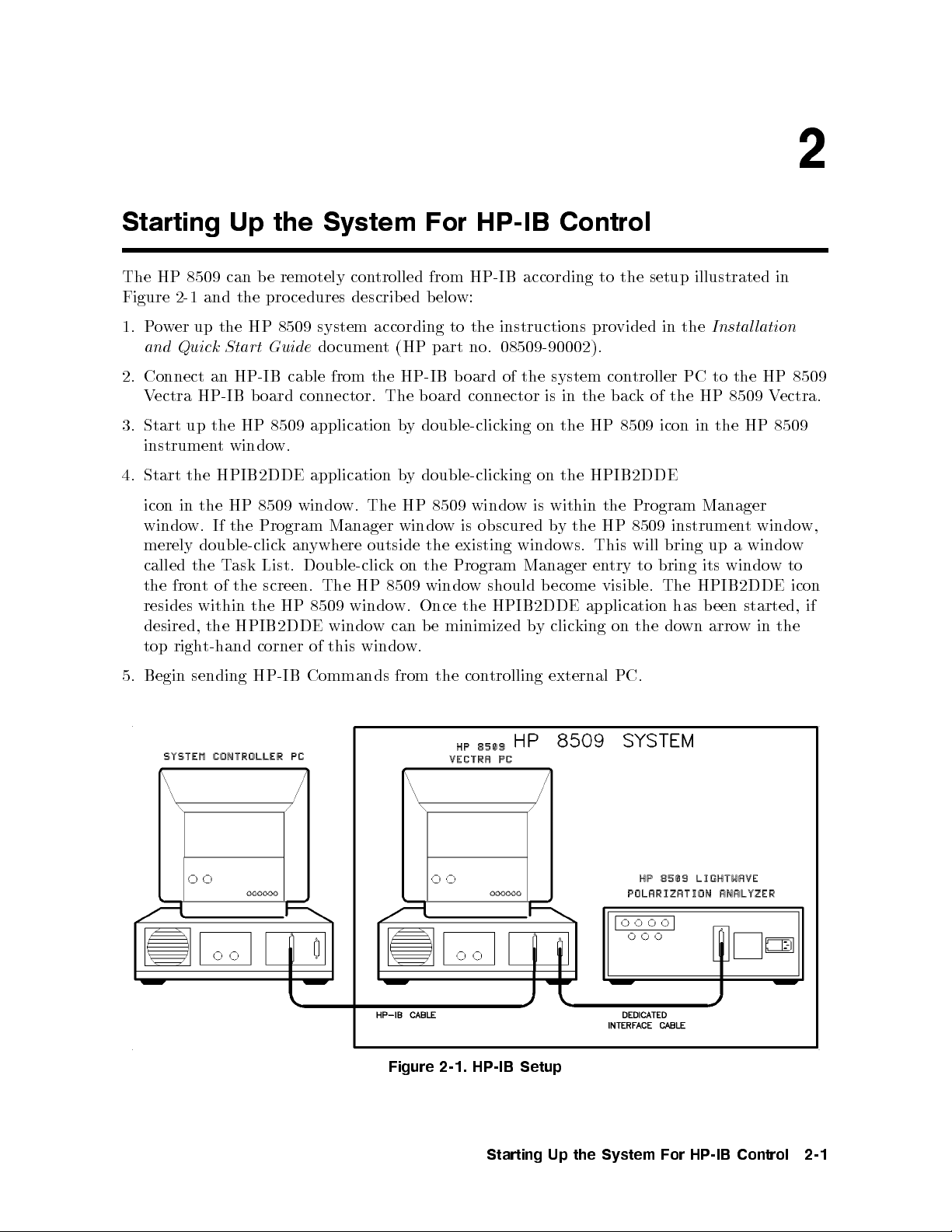
2-1. HP-IB Setup . . . . . . . . . . . . . . . . . . . . . . . . . . . . 2-1
4-1. HP-IB to DDE Gateway.. . . . . . . . . . . . . . . . . . . . . . 4-2
4-2. HP-IB Connections In a Typical Setup . . . . . . . . . . . . . . . . 4-7
Tables
8-1. Conventions . . . . . . . . . . . . . . . . . . . . . . . . . . . . 8-2
Contents-6
Page 13
1
Introduction
This chapter is an introduction to programming the HP 8509 polarization analyzer over
HP-IB (Hewlett-Packard Interface Bus) and over the DDE (dynamic data exchange). Its
purpose is to provide concise information ab out the operation of the instrument under remote
control. Some background information on the HP-IB and DDE is provided. A tutorial
introduction using elementary programming examples illustrates the basics of HP 8509 remote
control. The document also provides a command reference with a brief description of each
HP-IB/DDE command recognized by the HP 8509. Examples are provided on two disks that
are included with the
HP 8509 Users/Reference Guide.
The programs on these twodisks
illustrate the exact executable syntax, but the code is not explained in great detail. See the
README.TXT les on each disk for more information.
HP-IB
ailable
v
hapter
c
an
at
t BASIC
IBASIC and
BASIC
of
trol
con
IBASIC
for
using
not
is
ductory
tro
in
for Windo
part
(HP
Example
Example
con
main
The
through
command
the
HP-IB.
discuss
found
Programs Disk
Programs
troller.
cus
fo
external
an
The
HP-IB
the
in
this
of
reference
material
DDE
or
wing
follo
Information concerning
Instrument
Using
HP
- DOS
-
Disk
hapter
c
con
PC
(section
presen
theory
references:
HP Instrumen
BASIC
LIF F
is
troller
in
ted
except
Format,
ormat, HP
on
running
are a
8)
this
Windows
for
Information on HP Instrument BASIC is available in the
Handbook
(HP part no. E2083-90000).
Information on using the HP-IB is available in the
Hewlett-Packard InterfaceBus
cumentation
Microsoft
Additional
do
information
ab
out
(HP literature no. 5952-0156).
DDE.
of
measuremen
the HP
8509
following references:
VISUAL
example
HP
the
Windo
Microsoft
tended
in
lev
no.
BASIC/DDE
HP
an
for
olarization
p
8509
of the
Most
ws.
teac
ailable
v
a
h
ws
programming
information
el.
ws
Windo
to
Related
is
E2200-90000).
9000
DDE,
in
Instal
HP Instrument BASIC User's
Tutorial Description of the
found
e
b
t
pro
cedures
can
example.
200/300
series
analyzer
commands
ell
w
as
or
can
ling
the
in
in
as
to
be
and
HP 8509 User's/R
eferenc
e Guide
(HP part no. 08509-90010).
Introduction
1-1
Page 14

Page 15
Starting Up the System For HP-IB Control
The HP 8509 can be remotely controlled from HP-IB according to the setup illustrated in
Figure 2-1 and the procedures described b elow:
2
1. Power up the HP 8509 system according to the instructions provided in the
and Quick Start Guide
document (HP part no. 08509-90002).
Installation
2. Connect an HP-IB cable from the HP-IB board of the system controller PC to the HP 8509
Vectra HP-IB b oard connector. The board connector is in the back of the HP 8509 Vectra.
3. Start up the HP 8509 application by double-clicking on the HP 8509 icon in the HP 8509
instrument window.
Start
4.
icon
window.
merely
called
the
resides
desired,
top
Begin
5.
HPIB2DDE application
the
8509
HP
the
in
Program
If the
double-clic
the
t
fron
within
the
t-hand
righ
sending
T
of
k
List.
ask
screen.
the
HP
the
HPIB2DDE
corner
HP-IB Commands
window.
Manager
ywhere
an
Double-clic
The HP
windo
8509
windo
this
of
by
The HP
windo
outside
on
k
8509
w.
can
w
windo
from the
double-clicking
8509 windo
obscured
is
w
existing
the
Program
the
w
windo
the
Once
minimized
e
b
w.
con
on the
wis
windo
Manager
should
b
HPIB2DDE
y
b
trolling
HPIB2DDE
within
the
y
b
This
ws.
en
ecome
application
king
clic
external
Program
the
8509
HP
will
to bring
try
visible.
the
on
PC.
Manager
instrumen
up
bring
its
HPIB2DDE
The
een
b
has
arrow
wn
do
windo
t
windo
a
windo
started,
in
w
w,
w
to
icon
if
the
Figure
2-1.
HP-IB
Starting
Setup
Up
the
System
For
HP-IB
Control
2-1
Page 16

Page 17

3
HP-IB Overview
HP-IB (the Hewlett-Packard Interface Bus) is a high-p erformance bus that allows individual
instruments and computers to b e combined into integrated test systems. The bus and its
associated interface op erations are dened by the IEEE 488.1 standard. The IEEE 488.1
standard denes the interface capabilities of instruments and controllers in a measurement
system, including some frequently used commands.
HP-IB cables provide the physical link between devices on the bus. There are eight data lines
on each cable that are used to send data from one device to another. Devices that send data
over these lines are called
Talkers.Listeners
are devices that receivedataover the same lines.
There are also vecontrol lines on each cable that are used to manage trac on the data lines
to
lines
trol
con
these
use
and
sp
con
ecify
trol
the
other
talk
er
terface
in
and
op
listener
erations.
data
a
in
trollers
Con
exchange.
are
devices
that
con
Active
system
the
on
whic
must
with
at
Con
t
device
h
be
or
y
an
troller
con
times.
bus.
unique.
rear-panel
a
When
one
curren
con
function
HP-IB
HP-IB
exc
the
default
an
the
of
tly
troller-capable
as
addresses
addresses
hange.
device
address
HP-IB
devices
con
system
is
trolling
devices
er,
talk
a
pro
to
means
This
itself, using
for
allo
data
a
vide
sp
the
tains
con
ed to
w
exc
can b
listener,
w
a
whic
ecify
eac
that
either a
8509
HP
more
control
hanges
designated
e
or
to
y
a
h
device's
h
fron
is
is
con
a
iden
device
t-panel
29.
one
than
exc
data
called the
as
troller
tify
at
devices
talks
address
ey
k
device
hanges
the
dieren
and
sequence
Bus Structure
Data Bus
bus
data
The
Programming
consists
of
commands
eigh
and
lines
t
data sen
that
t
are used
these
on
to
lines
transfer
is
data
ypically
t
format, although binary encoding is often used to sp eed up the
I format is a
ASCI
undergoes a
vailable to the HP 8509. In addition, ev
handshake
to ensure v
alid data.
ery b
device
one
8509
troller
data
a
address
The
to
only
the
of
can
uses
set
is
factory
another.
I
troller
en
giv
troller.
The
listens
A
from
enco
capabilities,
time.
Also,
.
The
e
activ
during
device's
switc
one
ded
The
only
HP
con
h.
device
the ASCI
in
transfer of large arrays. Only
yte transferred o
ver HP-IB
on
HP-IB
Ov
erview
3-1
Page 18

Handshake Lines
A three-line handshakescheme co ordinates the transfer of data between talkers and listeners.
This technique forces data transfers to o ccur at the speed of the slowest device, and
ensures data integrityinmultiple listener transfers. With most computing controllers and
instruments, the handshake is performed automatically, which makes it transparenttothe
programmer.
Control Lines
The data bus also has ve control lines that the controller uses b oth to send bus commands
and to address devices. The HP 8509 makes explicit use of the EOI line through the
HP-IB END statement used to terminate all command transmissions. A brief description of
the ve HP-IB control lines is provided below.
IFC
ATN
Q
SR
REN
EOI
Interface Clear. Only the system controller uses this line. When this line is true
(low) all devices (addressed or not) unaddress and go to an idle state.
Attention. The activecontroller uses this line to dene whether the information
data
the
on
the
in
command
the
(high)
instructions
Service
activ
Remote
true
listen
Request.
con
e
enable.
w)
(lo
or
talk.
instructions
(high)
false
Iden
or
End
b
ultiple
m
is
bus
and
de
mo
is
bus
data.
or
services
troller
Only
bus
the
When
from
bus
the
This
.
tify
transmission,
yte
command
a
the
the
in
This
in
is
the
HP-IB
and all
data
line
the
the
line
or
carry
lines
data
and
de
mo
true
is set
requesting device.
the
remote
in
is
than
con
mo
remote
system
bus
rather
devices return
ya
used b
is
an
y
b
or
bus
the
w)
(lo
troller
de
from
talker
active
commands.
data
when
uses
devices
and
a
and
fron
its
lo
to
to indicate
controller
lines
a
this
device
t
op
cal
carry
device
line.
are
is
panel.
eration.
the
to initiate
this
When
device-dep
requests
this
When
addressed
addressed,
this
When
data
last
a parallel
line
enden
service;
line
either
receiv
it
line
yte
b
is
is
to
is
p
false
t
the
set
es
set
in
oll
a
bus
the
w)
(lo
true
is
line
this
When
.
data
is
sequence. The analyzer recognizes the EOI line as a terminator and it pulls the
EOI line with the last byte of a message output (data, markers, plots, prints,
error messages).
is
3-2
HP-IB
Ov
erview
Page 19

Sending Commands
Commands are sentover the HP-IB via a controller's language system, such as IBASIC,
QuickBasic or C. The keywords used byacontroller to send HP-IB commands vary among
systems. When determining the correct keywords to use, keep in mind that there are two
dierent kinds of HP-IB commands:
Bus management commands, which control the HP-IB interface.
Device commands, whichcontrol analyzer functions.
Language systems usually deal dierently with these two kinds of HP-IB commands. For
example, for most HP instrumentation, HP BASIC can use a unique keyword to send eachbus
management command, but always uses the keyword OUTPUT to send device commands.
It must be noted, however, that for the HP 8509, all commands must be sent using the
OUTPUT statement.
The following example shows how to send a typical device command in IBASIC:
OUTPUT 729; "POINCARE:CLEAR" END
This sends
address
729.
measured
the command
device
the
If
the
traces
from
ADDITIONAL INF
HP-IB
The
b
set
is
within the
is
oincare
P
card
adjusting
y
an
HP
select
quotes
8509,
sphere.
ORMA
co
switc
(POINCARE:CLEAR)
command
the
instructs
TION
HP-IB
the
and
7
is
de
HP-IB
the
on
hes
card
the
to
analyzer
the
address
inside the
HP-IB
to
The
29.
is
computer.
device
clear
select
all
at
co
de
HP-IB
Ov
erview
3-3
Page 20

Page 21

4
HP-IB For the HP 8509
The HP 8509 system can be described as a Windows application, running on a Vectra
PC, which controls an external instrumentcontaining the system hardware. The system
hardware consists of all devices required by the HP 8509 software to conduct polarization
measurements. Remote control of the HP 8509 system is achieved through direct
communication with the system's Windows application software. Use an external controller
for remote control of the HP 8509.
Given that the HP 8509 software is a Windows application, Dynamic Data Exchange (DDE)
can b e used to communicate with and control the HP 8509 system. DDE is a \standard"
communication technique which is provided by a ma jority of Windows applications. In eect,
ust
to
order
in
translated
e
b
Windo
A
ws
second
commands
accessible
is
terface
in
running
ust
m
The con
HP-IB
that
set
under
also
troller
con
the
29. Figure
to
remotely
DDE
to
application
and
ws
the
Windo
within
m
oard
b
Microsoft
an
e
v
ha
PC
trollable
HP-IB
select
unicate
comm
messages.
directly comm
application
DDE
the HP
installed
e
b
ust
HP-IB in
send
can
instrumen
de
co
called
messages
8509
Windo
ws.
terface
HP-IB
ts.
the
of
4-2 demonstrates
HP-IB
via
Under
these
unicating with
HPIB2DDE
HP
the
for
The
b
the
oard
windo
HP
external
congured
system
on
messages
curren
The
8509
HP
ypical system
at
with
conditions,
8509 soft
In
w.
system
8509
PC
directly
ersion
v
t
system
8509
HP
the
the
the HP
provides
8509 system
the translation
ware.
to
order
ectra
V
troller
con
running
for
HP
the
to
HPIB2DDE
of
and that
is 7
conguration.
system,
HP-IB in
HPIB2DDE
The
HPIB2DDE,
run
PC
running
under
8509
assumes,
HP-IB
the
HP-IB
terface is
soft
congured
and
Windo
Microsoft
system
w
b
b
are.
et
and
oard
messages
seen as
een
w
program
HP-IB
an
IBASIC
ws
Windo
to
default,
a
as
address
m
a
HP-IB
for
ws.
other
is
Warning
When receiving HP-IB commands, the HP 8509 does not lock out manual
operation. Take care not to disrupt remote control through manual command
execution. Furthermore, HP-IB commands which lock out manual operations
are not currently available for remote control of the HP 8509. When beginning
remote operation of the HP 8509, be sure to quit, then restart the application if
HP
session
8509
there has
HP
the
of
been
8509
manual
any
application.
operation
of
the
HP
8509
during
HP-IB
the
For
current
the
4-1
Page 22

HP-IB to DDE Interface
The HP 8509B LightwavePolarization Analyzer uses Dynamic Data Exchange (DDE) for
remote operation. The HPIB2DDE.EXE application connects the DDE system to the
HP-IB bus. Therefore, it is required to run this application before attempting remote
operation of the HP 8509B using HP-IB. To start the HPIB2DDE.EXE application, select the
NNNNNNNNNNNNNNNNNNNNNNNNNNNNNNNNNNNNNNNNNNNNNNNNNNNNNNNNNNN
HPIB TO DDE GATEWAY
There are three basic parts to this window, the `HP 8509 Control' frame, the `HP-IB' frame,
and the `Dynamic Data Exchange (DDE)' frame. The HPIB2DDE.EXE application window
appears as below when the application starts. The `HP-IB to DDE Gateway' is a oating
window when the program starts. This means that the window will always appear on top of
any other window. To defeat this feature, minimize the windowby clicking once on the down
arrow in the top right corner. When the application is restored by double clicking on its icon,
the window will no longer oat.
icon in the HP 8509 Group.
4-2
HP-IB
For
the
HP
8509
Figure 4-1.
HP-IB to DDE Gatew
ay
Page 23

`Command Line' Setup Options
The HP-IB gateway program may b e congured using command line parameters at runtime.
Two command line parameters are available and may be added to the HP-IB gateway icon's
properties. This selection can be found by highlighting the icon byclicking once on it, then
selecting \FilejProperties" in the Windows Program Manager. Add the command line
parameter after the name of the program in the `Command Line' text b ox.
/Errors Only
Add this command line parameter to congure the HP-IB gateway to record
only
HP-IB
bus errors, DDE link errors, Windows critical errors, and HP8509 commands whichdidnot
return a status of PASS, when `Log On' is checked. If this parameter is not sp ecied, all bus
transactions, including errors, are recorded in the log le. During program execution this
feature may be turned on and o byclicking the right mouse button on the `Log On' check
box.
/HP8509=<Name of executable
system uses
DDE
Windo
The
HP8509
link.
ersion
v
HP8509
is
/HP8509TimeOut=
This
for
ait
w
parameter
this
than
reset
will
le
log
ws
program. F
command
This
greater
2.
parameter
data
ecied time
the sp
the
en)
op
(if
than
sp
from
is
DDE
as
uture v
v
<
ecies
the
not
hannel
c
a
ersions
parameter
line
ersion
Number
the
HP8509
ecied,
sp
return
to
in
timeout
DDE
2.0.
n
the name
of
If
of
er
b
um
when
the
data
attempt
an
>
of the
HP8509
the
useful
is
parameter
this
Minutes
min
of
HP-
the
default
the
to
to
error.
The `HP-IB
executable le
only
>
the
utes
con
IB
used is
value
HP-IB
clear
y
ma
y
if
is not
`HP-IB
troller
con
the
a
use
HP8509
our
used, the
min
1
troller,
problem,
to DDE
to
dieren
DDE
to
requests
ute.
the
and
Gatewa
establish
name
t
are
w
soft
Name
<
Gatew
data
the
If
`HP-IB
record
y' will
DDE
a
establish
to
up
is
executable
of
program
y'
a
(sends a
HP8509
DDE
to
attempt
the
reset
link
dated to
query). If
es
tak
Gatew
itself
to
this
a
used
>
should
longer
a
in the
in
this manner ten times. After ten attempts, the `HP-IB to DDE Gateway' program will issue
a critical error and HP-IB operation will stop until the user acknowledges the critical error
issued by the `HP-IB to DDE Gateway.'
the
y'
Note
This timeout o ccurs only when the HP-IB controller requests data. The
a
queues
`HP-IB
sync
appropriate dela
that tak
to
HP8509
hronous
to
ys in the con
e more than 30 seconds (or 1/2 the timeout limit)
Gatewa
DDE
Remember0commands ma
y'
eration.
op
y still be in the `HP-IB to DDE Gatewa
command queue when the con
commands
all
programmer
The
trolling program after sending HP8509 commands
trolling program requests data. The execution
from
time to complete the commands still in the queue ma
HP-IB
the
should hard
y exceed the timeout
bus
de
co
to complete.
y'
limit.
8509
HP
the
HP-IB
For
4-3
Page 24

HP 8509 Control Frame
The elements in this frame provide a path for the development of HP-IB remote programs.
With the HPIB to DDE Gateway,you can send HP-IB commands, retrieve data, and savebus
trac to a le for later analysis. The elements of the HP 8509 Control Window are described
below.
NNNNNNNNNNNNNNNNNNNNNNNNNNNNNNNNNNNNNNNNNNNN
HP 8509 Status
Shows the status of the current DDE op eration. Valid choices are:
PASS: the remote command successfully completed.
FAIL: the remote command failed and did not complete.
PROBLEMS: the remote command experienced a problem during execution.
UNKNOWN: the remote command was not recognized.
BUSY: the remote command is in the pro cess of execution.
NO DDE LINK: the DDE link is not established.
N
N
N
N
N
N
N
N
N
N
N
N
N
N
List
the
a
is
This
Command
application
the
in
N
N
N
N
N
N
N
N
NN
N
N
N
N
N
N
N
N
N
N
N
N
list
text b
N
of
the DDE
all
ox.
directory
This
commands. This
loaded
is
x
o
b
list
.
list drops
reading
y
b
down
the
in
to
le
select
\DDE
command
a
CMD.TXT"
for
located
Command
application.
8509
HP
the
to
DDE
via
send
to
app
are
k
to
DDE
in
ear
recorded
feature
x.
bo
Gatew
this
text
to
ma
a
,
y
the
y
the
b
b
o
le
e
individual
x.
selected
turned
commands
with
and
on
4
Pick
o
File
yclic
b
4
Log On
that
5
acommand
ecify
sp
to
used
is
x
o
b
text
This
HP-IB
During
eing
b
4
On
Log
When c
4
File
Pick
mouse
t
righ
4
Pick File
normal
op
transmitted
5
ed, HP-IB
heck
button
5
button
5
eration of
the
to
disabled.
is
on
the
HP
transactions
bus
The
`Log
the
also
8509
/ErrorsOnly
On'
c
hec
Selects a le for logging HP-IB bus transactions. This button is disabled when
is selected. This lename is saved in the le C:nWindowsnWIN.INI under the heading
[HPIB2DDE]
4
Execute
Cmd
and
5
restored
is
Sends the command in the
4
Get Data
5
next
the
Command
the
time
text bo
HPIB2DDE
x via DDE to the HP 8509 application.
application
Retrieves data via DDE from the HP 8509 application. The data is
found in
4
5
Exit
Closes
the Dynamic Data Exc
HPIB2DDE
the
gatew
hange (DDE) windo
application.
y
a
w.
is started.
linked to the text bo
are
and the
,
king the
5
xes
4-4
HP-IB
For
the
HP
8509
Page 25

HP-IB Frame
This frame provides you with an interface to the HP-IB bus parameters. The elements of the
HP-IB window are described below.
NNNNNNNNNNNNNNNNNNNN
To LPA
Shows the user the command b eing sent to the HP 8509 that was received on the HP-IB bus.
NNNNNNNNNNNNNNNNNNNNNNNNNN
To HP-IB
Shows the user the data being sent to the HP-IB bus that was read from the HP 8509.
NNNNNNNNNNNNNNNNNNNN
Status
Shows the HP-IB card status and the time and date of any error. HP-IB bus errors, DDE
errors, and Windows system errors are also logged to a le when
4
5
EOL
4
Log On
5
is selected.
Select this b oxifevery HP-IB bus action is to end with a line feed. This setting is saved in
the le C:nWINDOWSnWIN.INI under the heading [HPIB2DDE] and is restored to this
setting
4
Address
the
5
next time
the HPIB2DDE
application is
started.
4
Initiate
the
4
Terminate
DDE
heading
started.
is
DDE Link
5
Link
[HPIB2DDE]
the
Put
enable
HP-IB
the
This
restored
is
4
Timeout
address
4
Address
setting
5
the
of
. Change
5
and
bus
ed
v
sa
is
setting
this
to
ADDITIONAL
4
erminate
T
the
in
8509
HP
the HP
DDE
the
the
DDE
here.
8509
link.
C:
le
next
INFORMA
5
Link
To
device
WINDO
n
time
4
and
Initiate
change
address
WS
HPIB2DDE
the
TION
DDE
the
then
WIN.INI
n
5
Link
address,
select
select
under
application
toggle selections.
are
Allows you to set the HP-IB timeout. This setting is saved in the le
C:nWINDOWSnWIN.INI under the heading [HPIB2DDE] and is restored to this
setting the next time the HPIB2DDE application is started.
Separator
Data
This
setting
is sa
WIN.INI
n
WINDO
n
C:
le
the
in
ed
v
WS
under the
heading
[HPIB2DDE]
is restored to this setting the next time the HPIB2DDE application is started.
Cr/Lf.
Sets the data separator to carriage return/line feed delimited.
Comma.
Sets the data separator to comma delimited.
to
5
to re-enable
and
and
HP-IB Exit State.
Allows you to set the HP-IB card to Controller or Non-Controller when the
program exits. This setting is saved in the le C:nWINDOWSnWIN.INI under the heading
started.
HP-IB
is
8509
HP
the
For
[HPIB2DDE]
and
restored
is
the
next
time
HPIB2DDE
the
application
4-5
Page 26
Controller.
Some applications may require that the HP-IB card in the HP 8509 is set to
Controller when the HP 8509 itself is not being controlled by the HP-IB bus. Other systems
may require that the HP-IB card never becomes a controller while on the HP-IB bus.
Non-Controller.
The HP-IB card is Non-Controller while the HPIB to DDE gateway
application is running.
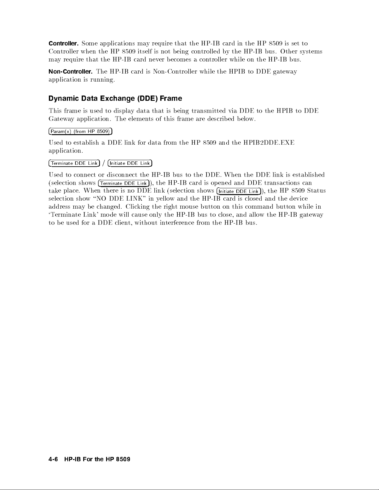
Dynamic Data Exchange (DDE) Frame
This frame is used to display data that is being transmitted via DDE to the HPIB to DDE
Gateway application. The elements of this frame are describ ed below.
4
Param(x) (from HP 8509)
5
Used to establish a DDE link for data from the HP 8509 and the HPIB2DDE.EXE
application.
4
Terminate DDE Link
5/4
Initiate DDE Link
5
Used to connect or disconnect the HP-IB bus to the DDE. When the DDE link is established
(selection shows
place.
e
tak
selection sho
address
`T
to
ma
erminate
used
e
b
4
Terminate DDE Link
When
there
w \NO
hanged.
c
e
b
y
mo
Link'
DDE clien
a
for
DDE link
no
is
DDE LINK"
king
Clic
cause
will
de
t, without
5
), the HP-IB card is opened and DDE transactions can
ws
in y
the
only
ello
righ
the
in
(selection sho
the
and
w
mouse
t
HP-IB
terference
bus
from
HP-IB
button
to
the
4
Initiate
card
on
close,
HP-IB
DDE Link
closed
is
command
this
and allo
bus.
the
),
5
and
wthe
HP
device
the
button
HP-IB
8509
while
gatew
Status
in
y
a
4-6
HP-IB
For
the
HP
8509
Page 27

Figure 4-2. HP-IB Connections In a Typical Setup
HP-IB
For
the
HP
8509
4-7
Page 28

Given the translation mode under which HP-IB control is achieved for the HP 8509 system,
certain constraints exist dictated by the HPIB2DDE application. The constraints are relative
to the full set of capabilities provided by the HP-IB interface (see references). The constraints
are listed b elow.
Data is transmitted and received as ASCII strings. In other words, only formatted data
transfers are possible.
EOI is used to indicate the completion of data transmission. The EOI can be set by using
an HP-IB
END
statementto
terminate the sending of a command.
EOL (default<cr><lf>) is NOT used by default. This can be
toggled from the HPIB2DDE application window and will stay at the last setting. EOL
should b e toggled \on" for HP-IB control
through an external PC controller running IBASIC for Windows. EOL stands for End Of
Line and refers to a string which denes the end of a command line when an OUTPUT
statement is sent. The HP-IB END statementserves as the line terminator.
Use only
the
Set
HP-IB
ENTER/OUTPUT (formatted
seconds
e
v
least
at
timeout
activit
to
HPIB2DDE
The
.
y
is
data transfers).
giv
to
the
olling
p
the
e
HP-IB
PC
time
card
recognize and
to
needs
and
time
respond
see
to
to
the
request.
capabilities.
ual
the
HP
t
of
op
curren
the
HP
bus
8509
orted
supp
HP
the
eration.
tly
8509,
HP
8509
system.
y
b
8509.
The
ailable
v
a
quit,
during the
ortan
imp
is
It
o
w
t
Only
These
are
Hewlett-P
When
user
F
for
then
receiving
ust
m
urthermore,
remote con
restart
note
to
t
HP-IB
bus
*OPC? and
instrumen
ard
k
ac
HP-IB
care
e
tak
HP-IB
trol of
application
the
the
that
managemen
*IDN?.
tation,
commands,
disrupt
to
not
commands
the HP
if
HP
Other
whic
8509.
there
8509
commands
t
bus
not
are
HP
the
remote
lo
h
When
b
has
utilizes
only
are supp
managemen
ailable
v
a
do
8509
trol
con
manual
kout
c
eginning
b
y
an
een
a
orted
commands,
t
the
for
not
es
through
op
remote
ual
man
subset
b
remote
k
c
lo
man
erations
op
eration
op
the HP-IB
of
curren
the
y
commonly
trol
con
man
out
command execution.
ual
not
are
eration
of
of
current session of the HP 8509 application.
A second alternative for remote control of the HP 8509, other than using an external PC
controller, is to use an HP 9000 series 200/300 controller running HP BASIC Version 5.0 or
later. The platform is the same as that shown in Figure 4-2, except that the PC controller is
as
of
yan
replaced
just
IBASIC syn
b
another
instrumen
tax is fully compatible with HP BASIC syn
used to create b
HP
HP
9000
series
on
t
the
200/300
HP-IB
con
bus.
troller.
The
tax. In eect, the same syn
oth IBASIC and HP BASIC programs. Ho
8509
system
can b
though
e
wever, the user should be a
t
tax can b e
ware
that IBASIC and HP BASIC le formats dier. IBASIC les are usually created in DOS
text format, while HP
IBASIC will not directly run under HP BASIC though the same syn
BASIC les are created in LIF format. In eect, a program created in
tax can b e utilized under
HP BASIC to create a program with identical functionality. Utilities exist under the UNIX
operating system to translate DOS formatted les to LIF format and vice versa.
4-8
HP-IB
For
the
HP
8509
Page 29
Basic Instrument Control
A computer controls the HP 8509 by sending it commands over HP-IB. The commands sent
are sp ecic to the HP 8509. Each command is executed automatically upon receipt. During
remote control, the analyzer is receptivetomanual control. The user must take care not
to disrupt remote operations. Most commands are equivalent to front panel functions. For
example, after preparing the system for HP-IB control, type:
OUTPUT 729; "POINCARE:CLEAR" END
on the alpha command line and execute by clicking the RUN button on the IBASIC control
pad.
5
oincare
P
The
measuremen
sphere
con
t
tin
on
ues
the
at
the
HP
8509
curren
displa
state
t
cleared
w
no
is
y
olarization. The
of p
all
from
construction of
measuremen
traces
t
the command
and
is:
is
data
and
8509).
aring
less
by
ly
the
by
The
on
the
the
the
the
to
out
DISPLA
Y
OUTPUT
"POINCARE:CLEAR"
POINCARE:CLEAR
The
729;
END
command
erforms
p
menu and within that menu selecting the
command mnemonic
CLEAR
is derived from the menu option for equivalentmanual control.
to
d
e
8509
spher
e
marks,
same
addr
data
interfac
ess
mnemonic
e.
statement,
END
function
BASIC
The
cte
e
dir
devic
the
HP
The
ar
Poinc
quotation
OUTPUT
terminating
the
CLEAR SPHERE
(HP-IB),
7
e
(the
29
mnemonic,
sent
fol
statement.
HP
cle
for
al
liter
d
lowe
output
The
is
statement.
selecting
as
option. As can be noted, the
Most of the HP 8509 HP-IB commands, where possible, are derived from the equivalent menu
option lab el. Otherwise, they are derived from the common name for the function.
form
the
in
command
8509
HP
the
e,
v
o
where
.
ab
P1:P2:P3
.are
.
.
parameters
the
noted from
e
b
can
As
COMMAND:P1:P2:P3:
of
command and
the n
example
the
.
.
umber of parameters depends on the function performed b
If, for example, the function of the command is to perform a t
ber of required parameters will v
num
ary with measuremen
the HP 8509 Command Reference section of this do cumen
the HP
8509 instrument windo
w for specic command information.
t pro cess complexity
tortothe
syntax
ype of measuremen
is
the
ertaining
p
to
y the command.
t, the
. Please refer to
Remote Access les in
The
END
following the
CLEAR
terminates the command inside the HP 8509 (EOI set true)
and prepares the HP 8509 for the next command. If there is a syntax error in the command,
found,
is
and
it
the
next
Control
8509
HP
the
incoming
terminator
ignore
will
commands
lost.
are
pro
the
cess
command
normally
lo
and
Characters
.
ok
for
b
the
et
w
next
een
the
terminator.
tax error
syn
Basic
When
Instrument
5-1
Page 30

The
OUTPUT 729;
statement will transmit one item at a time when a terminating
END
is used. It will transmit literal information enclosed in quotes, numeric variables, and string
variables. Without the
is suppressed by terminating the command with an
END
, a carriage return, line feed is transmitted after each item. This
END
statement.
Setting a display state is just one form of command the HP 8509 will accept. It will also
accept commands that require specic, user dened operands. For example, execute:
OUTPUT 729; "SETMARKER:1:0:1:0:A" END
In resp onse, the HP 8509 will place marker A at the Poincare sphere location corresponding to
the Stokes parameters S0=1, s1=0, s2=1, and s3=0. This corresp onds to full 45 degree linear
polarization. The HP 8509 will also accept commands that turn various functions on and o.
Execute:
OUTPUT 729; "POINCARE:HOLD:ON" END
This causes the HP 8509 to freeze the Poincare sphere display at the current measurement
trace. To initiate continuous measurement, execute:
OUTPUT 729; "POINCARE:HOLD:OFF" END
the
can
As
function
HP
The
e
b
and
8509
noted,
command
the
the function
distinguish b
not
es
do
POINCARE
is
indicator of
etw
ON
een
or
upp
. The
OFF
er
accompanying
.
er
w
lo
and
case
parameters are
or
letters.
F
example,
HOLD
execute:
example,
or
in
to
END
deal
ectra
V
the
data
with
execute:
as
PC
designated
END
storage
lo
the
driv
and
cation
or
F
e.
all
al
data
retriev
for
example,
the
using
storage.
execute:
SYSTEM.CFG
"poincare:hold:on"
of
729;
the
drive
directly
729;
HP-IB commands
8509
HP
F
ectra
V
PC
memory
.
"DRIVE:C" END
system
8509
HP
the
Cin
information
store
"SAVE:CONFIG:SYSTEM.CFG"
OUTPUT
Some
system
8509
OUTPUT 729;
sets
This
commands
OUTPUT
This causes the current system state or conguration to b e saved into the le
The le is created in the HP8509 directory of the drive, (usually drive C) known as
the working directory. This directory is sp ecied by the program manager in the
\File/Properties" menu. The default working directory is the directory where HP 8509
are
softw
directory
installed.
is
path
is
ecied.
sp
The
le
A
can
sav
b
ed
v
sa
e
system
in another
ed
state
can
directory
b
later
if
recalled
e
appropriate
an
y
b
executing:
DOS
OUTPUT 729; "LOAD:CONFIG:\HP8509\SYSTEM.CFG" END
Through this command, a user determined instrumen
the appropriate path to the conguration le
Reference" section of this documen
t for command sp ecic information.
must be sp ecied. Refer to the \Command
t state can be ac
hieved. Note that
HP
Some
.
format
5-2
Basic
Instrument
Control
Page 31
Data Requesting Commands
Some of the HP-IB commands request data from the HP 8509. This data is returned as an
ASCII string or as a series of ASCII strings separated by commas. It can be accessed by
following the data-request command with an
ENTER
remote command. An example is given
below:
OUTPUT 729; "JONES:MEASURE" END
OUTPUT 729; "JONES?" END
ENTER 729; String$
The device command
measurement of an inserted DUT. The results are requested through the
The data is transferred through the
named
String$
.
JONES:MEASURE
ENTER
directs the HP 8509 to conduct a Jones matrix
JONES?
command.
remote command and placed in a string variable
There are twotypes of HP-IB commands which request data from the HP 8509 system. Some
commands, suchas
JONES:MEASURE
, cause a measurement to be conducted bytheHP
8509 while others request information regarding a particular instrument state. As an example
execute:
e
yp
729;
set
tly
named
information
binary
of
HPIB2DDE
the
8509
large,
tly
t
"DRIVE?"
String$
DRIVE?
for
up
String$.
statemen
data
the string
into
matc
ust
data
END
causes
transfers.
data
ENTER
t
the
to
output
application.
v
data
the
h
lost.
is
the
addresses
troller
con
the
y
b
ariable
the
HP
HP
listed
HP
8509
This
The
letter
the HP
PC.
8509
con
in
8509
system
is
ecically
Sp
and
troller
ENTER
the
has
return
to
read from
to
8509
the
,
reformats
places
PC
statemen
transmit.
to
talk.
it
letter
the
8509
HP
the
allo
This
ENTER
bac
the
If
statemen
to
in
k
data transmitted
The
t.
ariable
v
the
the
of
to
in
the
ws
an ASCI
string
driv
the
HP
t
not
is
which
e
string
8509
es
tak
string
I
by
ariable
v
the
second
the
of
OUTPUT 729;
ENTER
command
The
curren
is
ariable
v
IBASIC
The
transmit
to
stream
through
HP
the
dimensions m
sucien
Basic
Instrument
Control
5-3
Page 32

Operation Complete
Occasionally there is a need to nd out when certain operations have completed inside the HP
8509. For instance, a program should not have the op erator connect the DUT while the HP
8509 is still measuring the measurement thrupath.
To provide such information, the HP 8509 has an Op eration Complete reporting mechanism
that will indicate when certain key commands have completed operation. The mechanism is
activated by sending
output a 1 when the command completes execution. The
*OPC?
immediately after an OPC'able command. The HP 8509 will
*OPC?
command should o ccur in
the same output statement as the command being OPC'd.
As an example, when ready for remote control, type in the following program:
10 OUTPUT 729; "JONES:ABSOLUTE" END
20 OUTPUT 729;
"JONES:CALIBRATE;*OPC?" END
40 DISP "Measuring"
String$
"DONE"
causes
eing
b
729;
pro
t
the
executes
t
The
cedure.
assured
con
troller
con
that
PC
thrupath calibration
a
troller
When
PC
the
there is
50
60
70
program
This
the
while
matrix
measuremen
the
ue
tin
con
ENTER
DISP
END
instrumen
measurement.
on,
ADDITIONAL INFORMATION
Some op erations on the HP 8509 may take more time than the HP-IB
bus provides for a timeout. Therefore, when you send
execute a delay before
ON TIMEOUT
... in the IBASIC program to allow for this delay.
displa
to
displa
will
DONE
alid thrupath
av
ENTER
Set up for an absolute measurement.
Conduct the thrupath calibration and OPC the
thrupath calibration measurement.
issues
out
t
.
the HP
seconds
3
Jones
completes
then
pr
The
ompletes
c
8509
Measuring
the
y
in preparation
DONE
y
message
wil
am
gr
o
the
just
ears,
app
calibration in
halt
l
me
message
as
the
this
at
ement
asur
an
for
instrumen
the
program
memory
*OPC?
oint until
p
and
for ab
absolute
could
, either
, or trap the HP-IB timeout error using
1.
a
5-4
Basic
Instrument
Control
Page 33

Preparing For HP-IB Control
At the beginning of a program, the HP 8509 has to be taken from an unknown state and
brought under computer control. One way to do this is with an ab ort/clear sequence.
ABORT7
is used to halt bus activity and return control to the computer.
CLEAR 729
will
then prepare the HP 8509 to receive commands by clearing syntax errors, the input command
buer, and any messages waiting to be output.
The ab ort/clear sequence makes the HP 8509 ready to receive HP-IB commands. The
next step is to put the HP 8509 into a known state. The easiest way to do this is to send
LOAD:CONFIG:PRESET
, which returns the instrument to the preset state.
The user can specify dierent conguration parameters and then save them by sending
SEND:CONFIG:<"lename">.
To load the user specied conguration parameters send
LOAD:CONFIG:<"lename">.For
syntax, see Chapter 8, Remote Command Reference.
Running the following program brings the HP 8509 to a known state, ready to respond to
HP-IB control.
ontr
al
the
l
c
HP-IB
10
20
30
40
ABORT
CLEAR
OUTPUT
END
END
7
729
729;
"LOAD:CONFIG:
PRESET"
halts al
This
omputer.
c
the
to
ars
cle
This
eset
e,
the
interfac
Pr
instrument
action and
lbus
HP-IB
l
al
ars
cle
and
instrument.
window
err
syntax
menu
ors,
This
settings.
gives active
esets
r
ors.
err
esets
r
ol
Basic
Instrument
Control
5-5
Page 34

Page 35

6
Interacting with the HP 8509A/B Through the DDE
This chapter focuses on using Microsoft Visual BASIC for Windows (VB) to create a custom
application for programmed control of the HP 8509 to directly and continuously exchange
data with other Windows-based applications that support the Dynamic Data Exchange
(DDE). DDE data exchanges are called \conversations". DDE conversations are started by
establishing DDE links. Applications using DDE to converse with the HP 8509 for automatic
control can be custom programs using a computer language such as 'C' or Visual BASIC for
Windows. They can also be applications such as Microsoft Excel, that allow users to interface
to the DDE system.
Establishing
in
allo
HP8509
the
the
out
of
of
ject
of
name
vide
pro
re-compiled. F
be
HP8509
The
els'
'lab
things ab
name
The
sub
The
name
The
the
Since
should
ou
y
program to
ws
item
the
the
the
of
DDE
the
Links
applications
other
are. T
rmw
an
w
it
application
ersation,
v
con
with
item
8509
HP
hanism for
amec
o
link
to
ts
w
it
h
whic
application
wing
ollo
to
establish
to:
to
ts
an
called
DDE
the
the HP
is
establish
talk
topic.
a
ma
DDE
DDE
a
to.
ersation should
v
con
hange
c
y
8509 application
de
co
VB
a
links
an
link
with
fragmen
text-based
to
application
take
hange
c
allo
updates
future
to
that
t
m
place.
without
y
ws
controls
kno
ust
of the
to
ou
called
three
w
w
rm
requiring
ecify
sp
are,
the
the
HP 8509 application name as a command line parameter to his program. The command line
parameter may be specied in the Windows Program Manager properties dialog, accessed
in the menu FilejProperties. Place the parameter after the name of the program in the
Command entry.
fragment
code
this
Use
'
run
application
'
this
that
'
at
code
fragment
' /HP8509=<Name of
to
looks
command
for
time. The
HP8509 Program>
is:
line
parameter
HP8509
the
of
name
the
get
' If parameter not present, use the default name.
' Use the
variable Hp8509DdeName$ when establishing DDE links.
Interacting
with
the
HP
8509A/B
Through
the
DDE
6-1
Page 36

Const HP8509_DDE_DEFNAME$ = "HP8509_2" ' Get the name of the HP8509 Application
UCaseCmd$ = Trim$(UCase(Command$))
i% = InStr(UCaseCmd$, "/HP8509=")
If i% = 0 Then
Hp8509DdeName$ = HP8509_DDE_DEFNAME$
Else
i% = i% + 8
j% = InStr(i%, UCaseCmd$, " ")
If j% = 0 Then j% = Len(UCaseCmd$) + 1
Hp8509DdeName$ = Mid$(UCaseCmd$, i%, j% - i%)
End If
The HP8509 uses nine link items. One item is used to convey DDE status information. The
name of this DDE link item is: Status. Eight items are used to send data to the application
via DDE. The name of these DDE link items are:
Param(0)
Param(1)
Param(2)
aram(3)
P
aram(4)
P
aram(5)
P
aram(6)
P
aram(7)
P
the
is
pip
\lpadde",
prop
e
lpadde".
j
2
versations.
DDE
The
DDE
the
and
opic
LinkT
application
Microsoft
Automatic
LinkItem
the
with
VB
link
opic
of DDE
es
in
in
VB,
topic
prop
separated
HP8509
the
of
\HP8509
yis
ert
links for
y
b
DDE con
items
link
topic
prop
name,
Windo
ert
ws
.
y
the
are sp
are
The
VB
uses
com
DDE
3
ecied
bined
LinkT
yp
t
: The source supplies data to the application every time the data dened bythe
LinkItem changes. This link is also commonly called a HOT Link.
Manual
: The source supplies data only when the destination requires it. This link is also
commonly called a COLD Link.
hanges,
c
data
the
Notify
when
The
:
destination
the
source
noties the
requests
destination
it.
when
.
y
ert
haracter
c
The
(
so com
supplies
but
Application
DDE
is
and
),
j
bined with
called the
the
only
data
6-2
Interacting
with
the
HP
8509A/B
Through
the
DDE
Page 37
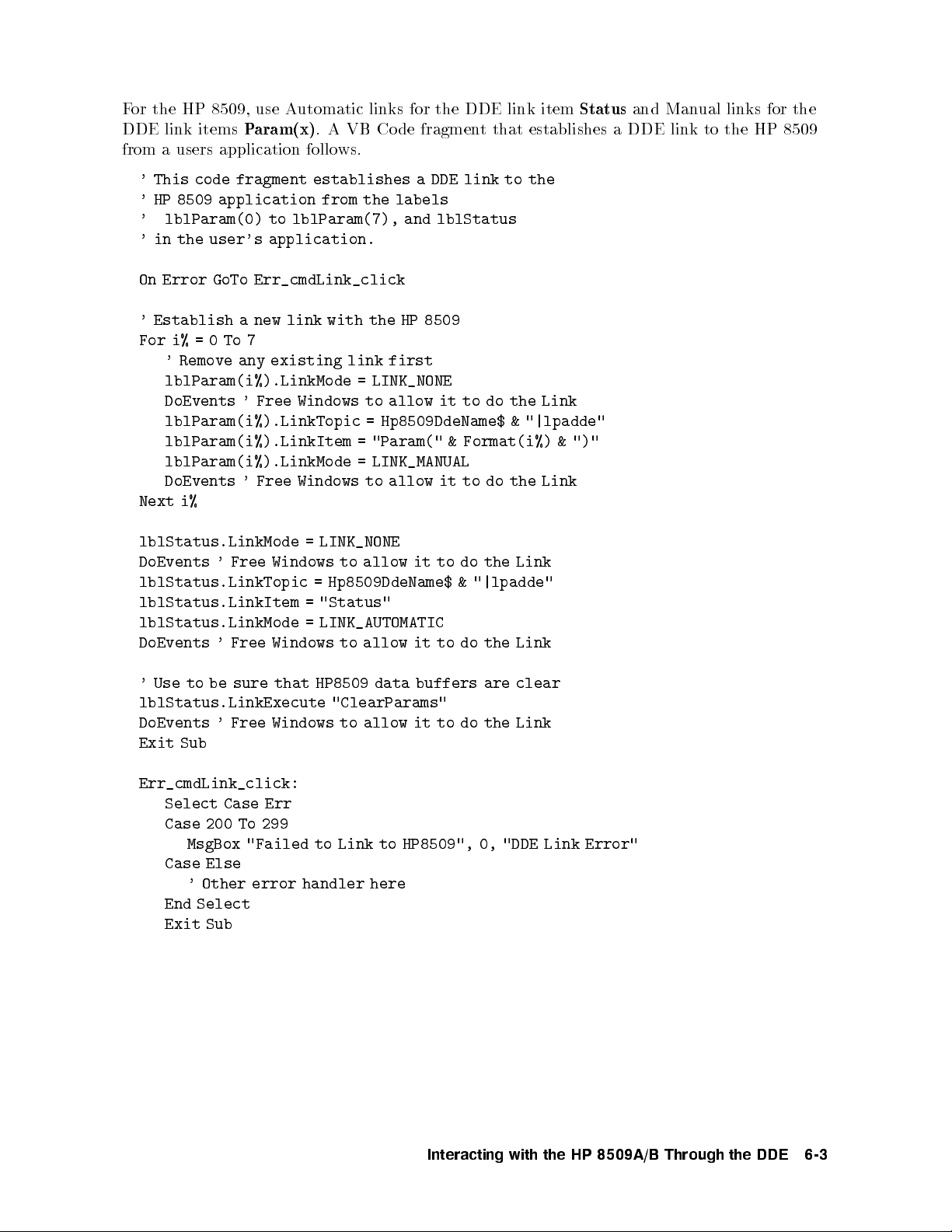
For the HP 8509, use Automatic links for the DDE link item
DDE link items
Param(x)
. A VB Code fragment that establishes a DDE link to the HP 8509
from a users application follows.
' This code fragment establishes a DDE link to the
' HP 8509 application from the labels
' lblParam(0) to lblParam(7), and lblStatus
' in the user's application.
On Error GoTo Err_cmdLink_click
' Establish a new link with the HP 8509
For i%=0To7
' Remove any existing link first
lblParam(i%).LinkMode = LINK_NONE
DoEvents ' Free Windows to allow it to do the Link
lblParam(i%).LinkTopic = Hp8509DdeName$ & "|lpadde"
lblParam(i%).LinkItem = "Param(" & Format(i%) & ")"
lblParam(i%).LinkMode = LINK_MANUAL
Link
the
DoEvents '
i%
Next
Free Windows
lblStatus.LinkMode
DoEvents
'Free
Windows
lblStatus.LinkTopic
lblStatus.LinkItem
lblStatus.LinkMode
Windows
Free
DoEvents
'
to allow
LINK_NONE
=
allow
to
Hp8509DdeName$
=
"Status"
=
LINK_AUTOMATIC
=
allow
to
it
it
it to
to
to
do
the
do
"|lpadde"
&
the
do
Link
Link
Status
and Manual links for the
that
sure
be
to
Use
'
lblStatus.LinkExecute
DoEvents
'Free
Windows to
Exit Sub
Err_cmdLink_click:
Select Case Err
Case 200 To 299
MsgBox "Failed to Link to HP8509", 0, "DDE Link Error"
Case Else
Other
'
error
handler
End Select
Exit Sub
HP8509
data
"ClearParams"
allow it
here
buffers
to do
are clear
Link
the
Interacting
with
the
HP
8509A/B
Through
the
DDE
6-3
Page 38

Sending HP 8509 Commands via DDE
To send commands to the HP 8509 using DDE use the LinkExecute method in VB. Be
sure that a previous DDE conversation is complete before sending the DDE command. The
following VB code fragment illustrates how to send the DDE command \Poincare:Center:A"
once the DDE Links have been established. The \ClearP arams" command is sentasa
precaution to clear out the HP 8509 data buers (Param(x) lab els). It is required that these
buers are empty before any commands are sent to the HP 8509. Generally the data buer is
empty unless a previous command prepared a response by the HP 8509. If you are not sure if
the buers were previously cleared, clear them before sending a command.
Do While lblStatus.Caption = "BUSY"
DoEvents
Loop
' Use to be sure that HP 8509 data buffers are clear
lblStatus.LinkExecute "ClearParams"
lblStatus.LinkExecute
DoEvents
'Free
Windows to
"Poincare:Center:A"
allow it
to do
the
LinkExecute
6-4
Interacting
with
the
HP
8509A/B
Through
the
DDE
Page 39

Retrieving HP 8509 Data via DDE
To retrieve HP 8509 data, use the VB LinkRequest method. The HP 8509 places data in the
Param(x) labels. Use LinkRequest with the controls which are linked to the Param(x) lab els
in the HP 8509. Be sure that there are no p ending DDE conversations before attempting
to get the data, otherwise all the data may not b e present. Also, clear the data buers
(Param(x) labels) in the HP 8509 after getting the data. The following VB code fragment
illustrates how to get data from the HP 8509 via DDE.
Do While lblStatus.Caption = "BUSY"
DoEvents
Loop
For i%=0To7
lblParam(i%).LinkRequest
DoEvents ' Free Windows to allow it to do the Link
' Since data is sequential, once there is an
' empty label we're done.
For
Exit
Then
""
=
Next
lblParam(i%).Caption
If
i%
Required
'
to
do
after
getting
frmHpib.lblStatus.LinkExecute
the
HP8509
data
"ClearParams"
Interacting
with
the
HP
8509A/B
Through
the
DDE
6-5
Page 40

Page 41

7
Measurement Programming
Earlier sections of this document outlined how to get commands into the HP 8509. The next
step is to organize the commands into a measurement sequence. A typical measurement
sequence consists of the following steps:
1. Zero the instrument.
2. Calibrate the instrument.
3. Set up the instrument.
4. Connect the device.
5. Take data.
6. Transfer data.
of
e
yp
t
the
on
up
end
ed
ZERO
\Blo
dep
prior
command.
not
is
er
the
k
c
cap
starting
to
detecting
external
piece
a
or
measurement
a
y
an
laser."
dark
of
p
T
pap
ow
o
er while
this,
do
er.
actions within
The
measuremen
y
ver
ou
Zeroing
ha
the
sequence.
accurate
or
F
zeroing
the
If
1.
co
each
conducted.
t
can
measuremen
routine
e
v
is
HP 8509A
an
OPTICAL
step
e
b
ts,
eing
b
INPUT
in
The
done
it
erformed.
p
ou
y
measuremen
the
instrumen
remotely
ortan
imp
is
b
will
connector
should
t
sending
y
b
that
t
prompted
e
with
sequence
t
zero
e
b
the
receiv
the
to
connector
a
the
er
v
source.
w
o
p
co
If
b
will
er
connector
the
e
y
If
2.
OPTICAL
external
bloc
during
e
v
ha
ou
source
automatically
ed
k
the
HP
an
INPUT
is
zeroing
8509B,
connector
connected
that
so
eration.
op
y
ou
to
will
in
as
the HP
p
no
prompted
e
b
not
ab
1,
step
8509B External
will
er
w
o
e,
v
o
emerge
or
from
but
to,
turn o
Source
the
must
you
your
input,
Optical
either
external
its
Output
While the zeroing routine is running, a green \zero" message will appear inside the power
display in the upper left corner of the HP 8509 basic measurement screen, and the mouse
pointer appears as an hourglass. When the \zero" message disappears, and the mouse p ointer
changes back to an arrow, the zeroing routine is nished.
Measurement
Programming
7-1
Page 42

Calibrate the Instrument
Awavelength calibration can b e automatically p erformed on the HP 8509, if desired. This can
be done remotely by sending the
CAL:CALIBRATE
and
CAL:ON
commands. It should not
be necessary to perform more than one instrument calibration p er dayor even one p er week,
depending on room temperature changes and the accuracy required. If in doubt, a calibration
should b e performed. For more information on instrument calibration please refer to the HP
8509
User's/Reference Guide
.
Set Up the Instrument
All pertinent measurement parameters must be set. Set the type of source (internal/external,
wavelength) and set for internal or external polarizers. The number of steps in the set up
procedure depends on the type of measurement to be conducted. Some of the measurements
require a thrupath measurement calibration and/or application of a two-point or three-point
reference frame prior to the execution of the DUT measurement. One of the measurements,
stop
and
start
the
as
olarization
p
velengths,
wa
mo
the
de disp
um
n
ersion, requires
steps,
of
er
b
setting parameters
step
the
and
w
elength
v
a
such
separation.
Device
Connect
the
e
v
Ha
at
place
the
erator
op
this stage
connect
that
so
and
there
adjust
no
is
the device
danger
of
under
taking
test
data
(DUT).
the
from
adjustmen
All
device
while
ts
it
tak
is
e
eing
b
adjusted.
Data
e
ak
T
With the device connected and adjusted, conduct the desired measurement. The process
of taking data is dierent dep ending upon the type of measurement that is conducted.
For the ma jority of measurements, the taking of data is automatically performed. Certain
measurements, however, such as PMD under manual mo de, require a high degree of op erator
teraction.
in
y
b
done
e
b
can
When
taking
data,
the
op
erator
ust ensure
m
prop
er
hronization.
sync
This
using the *OPC? command.
Transfer Data
Lastly, read the results out of the instrument. The data output command is designed to
as
data,
The
ensure that
previously
measured
All
strings.
The
data
the
discussed,
data
erator
op
transmitted
e
b
can
returned
is
ust
m
read
tak
y
b
e
reects
from
the
care
the
the
8509
HP
reformat
to
t
curren
instrumen
system
or
state
using
t
as
parse
the
of
the
sequence
a
this data
instrumen
ENTER
of
if
t.
remote
command.
comma-separated
desired.
so
Measurement
7-2
Programming
Page 43
8
Remote Command Reference
Command Syntax
None of the commands are case dependent. Commands may be sent in upper case, lower case,
or mixed case. Any item not enclosed in angle brackets (
<,>
)must be considered a literal
command.
Most of the commands in this chapter are available using Microsoft Windows DDE, as well as
HP-IB. Any restrictions to the use of a command are noted in the chapter for that command.
When receiving HP-IB commands, the HP 8509 do es not lock out manual operation. Do not
disrupt remote control through manual command execution. Furthermore, HP-IB commands
the
HP
if
HP
which
8509.
there
8509
man
out
k
c
lo
ou
b
een
y
an
When
has
application.
b
y
ual
egin
man
erations
op
remote
ual op
are
eration
op
eration of
not
of
the HP
curren
the
ailable
v
a
tly
8509,
HP
8509 during
for
quit,
the
remote
con
then restart
session
t
curren
of the
trol
the application
of
Remote
Command
Reference
8-1
Page 44

Table 8-1. Conventions
:
colon Command
Separator
Separates parameters. A parameter must be supplied
to the rightofevery colon.
? question Query The command causes the instrument to prepare a
response. No further commands maybe sentuntil
the response is retrieved.
{}
braces Mandatory
Selection
Select one of the options in the braces as a
parameter. If braces indicate option is part of a
parameter, select option and app end it to the
parameter.
[]
brackets Optional Selection Similar to Mandatory Selection except that selecting
a parameter is optional.
|
pipe Selection Separator Separates mandatory selection and optional selection
parameters. Spaces may be added in this document
for clarity.
parameter
angle
<>
\lename"
<
brac
ets
k
Describ
parameter
>
ed
description
A
corresponding
lename
The
not
is
default
directory
application
Windo
icon
curren
command,
directory
enclosed
e
b
colons
should
sp
ws
driv
t
(
ecied,
sp
path
The
orking
w
HP8509
the
HP8509
the
Spec>
default
ust
m
y
an
of
path
and
),
:
parameter.
the
of
to the
le
the
exist,
ecied
for
This
.
directory
Program
selecting
changed
is
e
then
the
of
double
in
otherwise
description in
to
or
default
the
lename
y
an
is
Manager
the
curren
e
v
sa
error
an
usually
,
File
using the
default
quotes
double
the
Supply
or
path
but
b
drive.
t
|
a
the brac
The
load.
ccur.
o
will
b
will
windo
the
is
same
the
c
be
can
y highligh
Properties
Drive:<Drive
directory
The lename
it includes
if
)
"
(
quotes
ets.
k
path,
If
used.
e
ws
the
as
hanged
ting
.
is the
are
optional.
if
the
in
the
If
8-2
Remote
Command
Reference
Page 45

<
\title"
>
<
\serial number"
de"
co
\date
<
Table 8-1. Conventions (continued)
The title to use for a Save/Load operation with the
HP8509 database. A maximum of 80 characters can
be used for the
<"title">
. Use only printable
characters in the range of ASCI I 32 (space) and
ASCII 126 (~ tilde) for titles. Trailing spaces are
ignored, leading spaces are not ignored. The title
must be enclosed in double quotes (") if it includes
any colons (:), otherwise the double quotes are
optional.
>
The serial number of the device under test for the
measurement being saved. Used for a Save operation
with the HP 8509 database. This eld is optional. If
it is not provided, this entry in the database is left
blank. A maximum of 25 characters can be used for
the serial number. Use only printable characters in
the range of ASCII 32 (space) and ASCII 126 (~
tilde). Trailing spaces are ignored, leading spaces are
eration
op
is
used
in
tilde).
are
double
in
If
left
for
the
not
the
e enclosed
ust b
m
er
b
um
n
serial
quotes
co
HP
pro
maxim
A
co
ASCI
of
spaces
The
)
"
The
(\)
double
the
of
de
eing
b
t
8509
vided,
um
use
de.
32
I
are
date
includes
it
if
are optional.
includes
it
if
quotes
the device
ved.
sa
database.
try in
en
this
16
of
prin
only
(space)
ignored,
ust
m
de
co
an
an
optional."
are
under test
used for
This
the
haracters
c
table
ASCI
and
leading
e
b
colons
y
colons(:),
y
Sa
a
is optional.
eld
database
can
haracters
c
126
I
spaces
enclosed
otherwise
(:),
for
v
this
e
e
b
(~
in
ignored.
not
double
otherwise
>
The
date
measuremen
the
with
not
is
it
blank.
date
the
range
railing
T
ignored.
quotes (
double quotes
Remote
Command
Reference
8-3
Page 46
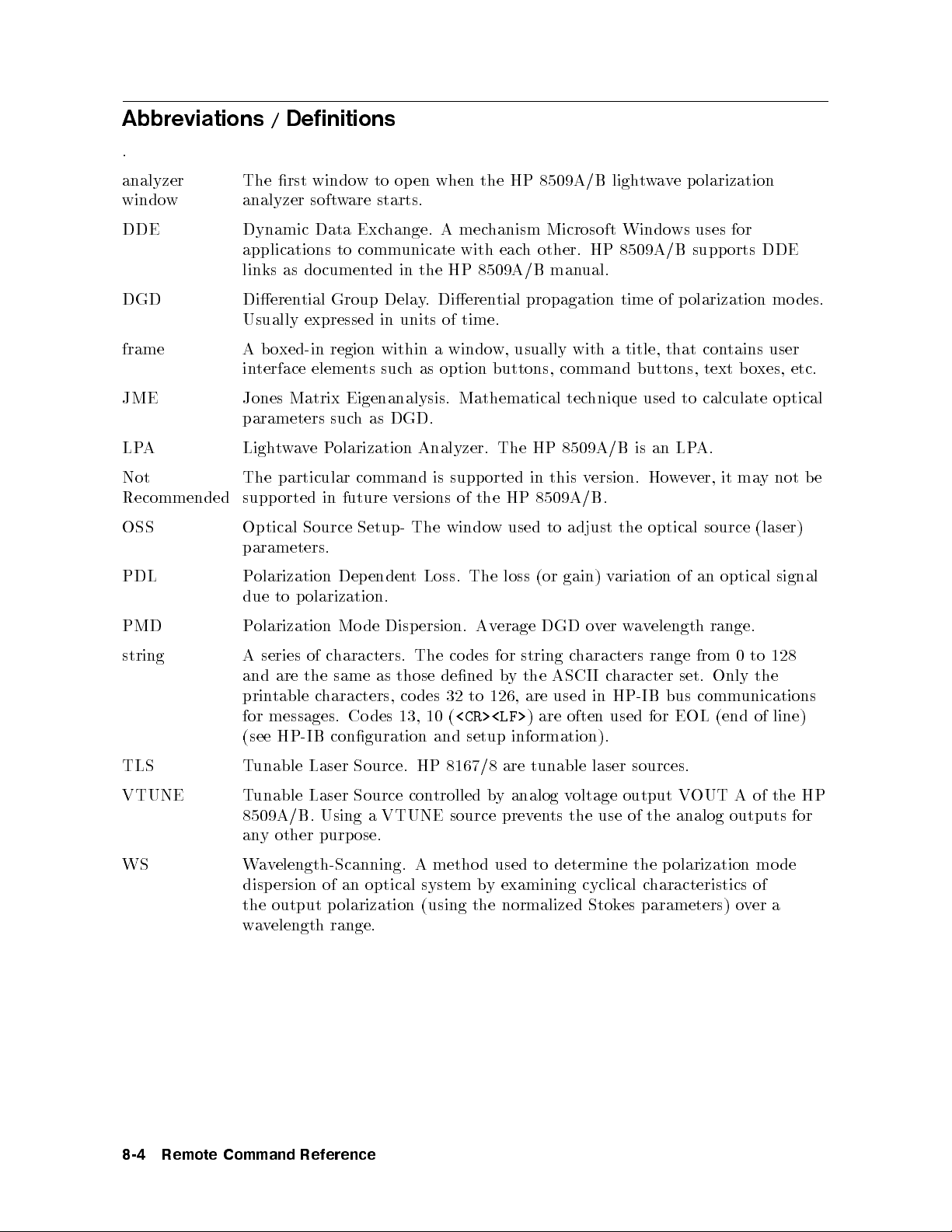
Abbreviations / Definitions
.
analyzer
window
The rst window to op en when the HP 8509A/B lightwave p olarization
analyzer software starts.
DDE Dynamic Data Exchange. A mechanism Microsoft Windows uses for
applications to communicate with each other. HP 8509A/B supports DDE
links as documented in the HP 8509A/B manual.
DGD Dierential Group Delay. Dierential propagation time of polarization modes.
Usually expressed in units of time.
frame Aboxed-in region within a window, usually with a title, that contains user
interface elements such as option buttons, command buttons, text boxes, etc.
JME Jones Matrix Eigenanalysis. Mathematical technique used to calculate optical
parameters such as DGD.
LPA LightwavePolarization Analyzer. The HP 8509A/B is an LPA.
Not
Recommended
OSS
particular command
The
future
in
orted
supp
Optical
Source
Setup-
ersions
v
The
is supp
of
windo
orted
the
w
in
8509A/B.
HP
used
this
to
ersion.
v
adjust
Ho
the optical
source (laser)
b
not
y
ma
it
er,
ev
w
parameters.
PDL
PMD
olarization
P
p
to
due
olarization
P
enden
Dep
olarization.
de
Mo
Disp
Loss. The
t
ersion.
Av
loss
erage
(or
DGD
gain)
o
ariation
v
er
v
w
elength
v
a
of
an
range.
optical
signal
e
128
to
0
set.
bus
from
Only
comm
(end of
the
unications
line)
string
series
A
and
table
prin
messages.
for
(see
of
the
are
HP-IB
haracters.
c
same as
haracters,
c
des
Co
conguration
des
co
The
those dened
to
32
des
co
<CR><LF>
(
10
13,
setup
and
string c
for
ASCI
the
y
b
used
are
126,
are
)
information).
haracters
haracter
c
I
HP-IB
in
used
often
range
for EOL
TLS Tunable Laser Source. HP 8167/8 are tunable laser sources.
VTUNE Tunable Laser Source controlled byanalogvoltage output VOUT A of the HP
8509A/B. Using a VTUNE source prevents the use of the analog outputs for
any other purpose.
de
WS
elength-Scanning.
v
a
W
disp
ersion
of
an
optical
method
A
system
used
y examining
b
cyclical
determine
to
the output polarization (using the normalized Stok
olarization
p
the
haracteristics
c
es parameters) o
mo
of
ver a
wavelength range.
8-4
Remote
Command
Reference
Page 47
Changes from Version 1.2 Software
Every eort has been made to assure the compatibility of version 2.0 remote commands
with version 1.2 remote commands. In some instances this has not been possible due to
fundamental changes in the design of the HP 8509 software. Please note the changes below
and change your existing programs to accommodate the changes, if necessary.
*OPC[?]
On some fast controllers, the windows operating system may not release system resources fast
enough to acknowledge an
*OPC?
that is sent in a separate bus transaction. In general, it is a
goo d idea to limit the number of HP-IB bus transactions by grouping the HP 8509 commands
together, separated by a semicolon. Four thousand (4,000) characters maybesentinone
HP-IB bus transaction to the HP 8509. It is recommended to send
part of the same HP-IB bus transaction as the command that is b eing
*OPC?
*OPC
to the HP 8509 as
'd.
Cal:Calibrate
command
This
issued,
either
calibration. No
completes.
y
an
to
out
ab
program
Status?
The
commands
seconds
25
which
command
alw
will
HP-IB
from
other activit
command
while
a
on
trols
con
to
return
ys
a
or
*OPC[?]
calibration
a
ectra
V
the
determine
\P
DDE,
yon
the
the HP
has
486/66. The
8509,
HP
the
if
V
eect,
system will
ectra
HP 8509
8509
no
in
is
progress.
programmer
issuing
after
Cal:Calibrate
PC
since
The
this
with
used
when
ASS"
Disper:Close
to close.
w
windo
PMD
all
will
w,
the
within
close
whic
h
a
only
holds
main
the
all
\Multiple
rst
the PMD
of
ersion
v
In
man
paren
ened.
op
PMD
y
t windo
1.2
c
w.
The
command
this
hild windo
command
This
paren
MDI
ws op
windo
t
caused
en,
automatically after the last PMD child window is closed.
Source? Source:External? Source:Internal?
Version
the
not
analyzer windo
commands, be a
ONLY. V
1.2 of the HP 8509 had only one set of settings to control a TLS, so when querying
TLS
the
softw
of
are.
In
ersion
v
TLS,
true
the
for
returned
ersion
v
w eac
v
2.0
hha
of
the
as
HP
alue w
vetheiro
setting
the
8509
wn set of TLS settings. When using the abo
ware that the TLS settings returned are for the ANAL
ersion
2.0 pro
vides other commands to query the TLS settings for the PMD
windows.
be
HP
After
occupied
place
e
tak
8509
DDE.
will
the
Cal:Calibrate
should
command.
command
hard
w
After
as
In v
cumen
Do
PMD:JME
c
child
8509
HP
the
for
h
eac
2.0
this command
erforming
p
til
un
system
will
command
dela
a
de
co
the
successful.
In
t
windo
2.0
terface"
ersion
hild
windows,
instrument.
windo
PMD
YZER
calibration
the
not
takes
in
y
issue
,
y
dela
can
there
(MDI)
whic
w
will close
and
w
ve
Source:
WINDOW
is
the
resp
the
h
This
b
w
the
ond
the
e
as
is
...
Note:
When
nm>,Source:External:{Off|On},
setting
the TLS parameters using the
and
Source:Internal:{Off|1310|1550}
Source:External:<Wavelength
commands, all windows' TLS settings are changed. This conforms to version 1.2
eration.
op
Remote
Command
Reference
8-5
Page 48

Common Commands
*IDN?
Returns a string that uniquely identies the analyzer. The string is in the form:
<Manufacturer>,<Model Number>,<Serial Number>,<Firmware Version>
for example:
"HEWLETT-PACKARD,HP 8509B,3206A00156,2.10"
HP-IB Op eration Only
*OPC[?]
Operation complete. The query will return an ASCII \1" when all p ending overlapped
operations have been completed. The command is used to ensure the completion of a
particular
OPC'd,
being
Device
function
as
separated
Specific
a
y
requested
with
b
semicolon.
a
Commands
prior
command.
App
end
this
command
to
command
the
Analog?
Analog:{
Returns
Off |
Off
Raw |
,
Raw
,
Stokes
Stokes
or
}
depending
on the
setting
of
the
analog
outputs
).
(see
Analog:Done
NNNNNNNNNNNNNNNNNNNN
Closes the
Analog:{
Selects and turns on or o the output of the four BNC connectors on the rear panel of
HP8509. If \stokes" is
proportional to the Stok
will b e proportional
Analog
|
Off
frame in the analyzer window.
[?]
Raw
Stokes
|
}
sent, the output of the four BNC connectors will be four v
es parameters S0, s1, s2 and s3. When ra
to the curren
ts induced on the four photodio des of the HP8509 receiv
w is sen
the four v
t,
the
oltages
oltages
The voltages are always in the range of010 to 10 volts. When \o" is sent, the four BNC
outputs will b e turned o. Please refer to the HP 8509 User's/Reference Guide for more in
depth
information.
frame of
Remote
8-6
the
The
analyzer
Command
query
w,
windo
Reference
returns
\0"
and
\1"
if
if
not
particular
the
selected.
con
trol
selected
is
in
the
NNNNNNNNNNNNNNNNNNNN
Analog
er.
Page 49

Angles:{ AB? | AC? | BC? }
Returns the angle between the specied markers, its cosine, and the cosine squared of half the
angle. The largest angle measurable is 180 degrees or PI radians. The angles and appropriate
markers must b e turned on in order to obtain the desired angle. (See
Angles:{ Off | On }
)
Angles:{ Degrees | Radians }[?]
Sets the units of the displayed angles to either radians or degrees. The query returns
the condition is true,
"0"
otherwise. (See
Angles:{ Off | On }
.)
Angles:Done
Not Recommended
Command maynotbeavailable in future versions. Plan your
programming
to
use
the
alternate
command:
Angles:Off
N
N
N
N
N
N
N
N
N
N
N
NN
NN
N
N
N
N
N
N
N
N
N
N
N
N
N
N
N
N
N
N
N
N
N
NN
NN
N
Closes
Angles:{
Displa
The
The
mark
the
Marker
Off
the
ys
measured
m
are
ust
angles
ers
|
angles
angles
measured
turned
e
b
Angles
}
On
w
et
b
are
frame
een
displa
from
on in
mark
ed
y
the
order to
in
ers
in
oincare
P
the
A
the
obtain
analyzer
B,
and
N
N
N
N
N
N
NN
Marker
sphere
N
N
N
N
the
mark
N
N
N
windo
ers
N
N
NN
N
N
N
N
N
N
N
N
N
N
Angles
co
measured
w.
and
A
N
N
N
N
N
N
N
N
N
N
N
N
frame
ordinate
C,
cation
lo
angles.
and mark
analyzer
the
in
of
B
ers
the mark
and
windo
ers. The
"1"
C.
w.
if
Average:Display:{ Off | On }
Turns on or o the moving average of a measurement trace on the Poincare sphere display.
Average:Display{
Species the n
sphere displa
analyzer windo
umber of poin
y. The query
w and the state of the displa
:<NumPoints>
|
?
ts
returns the n
<NumPoints>
}
to be used
umber of poin
eraging;
v
ya
in the mo
ts set in the
"0"
if o,
ving average of the P
NNNNNNNNNNNNNNNNNNNNNNN
NNNNNN
Averaging
"1"
if on.
frame of the
oincare
Average:Done
N
N
N
NN
N
N
N
N
N
N
N
N
N
N
N
N
N
N
N
N
N
N
N
N
N
N
N
Closes
N
the
Averaging
frame
in
the
analyzer
windo
w.
Remote
Command
Reference
8-7
Page 50

Average:Measure{ ? | :<NumPoints> }
The number of points (NumPoints) to be averaged, at each measurementpoint, when
conducting any measurement. This number may be set using
?
.
<NumPoints>
, or queried using
Cal?
Returns the status of the Calibration apply option buttons; \0" means Calibration is O, \1"
means Calibration is On.
Cal:Calibrate
Performs an instrument calibration which optimizes the measurement performance of the
analyzer. The calibration is performed at the current user-dened source wavelength. Refer
to the HP 8509A/B User's/Reference Guide for more in-depth information on the instrument
calibration
capabilities of
the HP
8509A/B.
Cal:{
The
windo
Done
Done
w
calibration
through
command
| Save
parameter
remov
is
erformed
p
source
the
sen
is
ed
t.
Cal:Delete:<Wavelength
}
terminates
the
from
giv
a
at
command.
the
screen.
source
en
All
nm>
instrumen
The
w
calibrations
ed
v
sa
Save
elength.
v
a
calibration
t
parameter
The
can
sequence.
es
v
sa
source
accessed
e
b
memory
in
v
a
w
The
elength
when
N
N
N
N
N
N
N
N
N
N
N
N
NN
N
N
N
N
N
N
N
N
N
N
N
N
N
N
calibration
instrumen
an
,
ecied
sp
is
the
Cal:On
N
N
N
N
N
N
N
t
Deletes from memory the instrument calibration performed at the specied source wavelength.
Cal:List?
list,
Returns
a
calibrations ha
comma-separated
a
of
form
the
in
ve been p erformed. The w
string, of
avelengths are giv
elengths
v
a
w
the
en in nanometers.
for
h
whic
Cal:{ Off | On }
The
Off
andOnparameters enable or disable the instrument calibration corrections. When
enabling a calibration, the instrument will searchforasaved instrument calibration performed
the
at
cannot
8-8
curren
enabled.
e
b
Remote
source
t
Command
elength.
v
a
w
Reference
calibration
a
If
calibration
then
t,
presen
not
is
corrections
Page 51

ClearParams
Used to clear the DDE parameters in the LPA after data is retrieved. A DDE LinkPokecan
also b e used to clear the parameter boxes. DDE Parameters should always be cleared after
data is retrieved so that another query isn't confused by residual data that was previously left
behind. The HP-IB gateway automatically sends this DDE command after retrieving data.
DDE only.
DBase:Close
Closes the currently opened database le.
DBase:Compact
Compacts the currently opened database le.
DBase:Filename?
ened
op
Returns
the
name of
the curren
tly
DBase:Open:<"filename">
"lename"
<
Op
ens
the
database
le
ecied
sp
in
DBase:Repair
Repairs the currently opened database le.
Disper
N
N
N
N
N
N
N
N
NN
N
N
N
N
N
N
N
N
N
N
N
NN
Displays
the
PMD:JME
before sending an
HP 8509B only
.
on
w
windo
y other `Disp er: .
HP
the
. . ' commands.
database
>
8509B
le.
.
instrumen
displa
t
Be sure
.
y
to
send
`Disp
er'
Remote
Command
Reference
8-9
Page 52

Disper?
Upon command execution, the analyzer returns the currentwavelength, the measured
dispersion at the currentwavelength, and the average of the measured dispersion up to and
including the currentwavelength. The command can be used under manual mode to checkthe
status of a running measurement pro cess. The data is returned as a comma separated ASCII
string in the following format:
<Wavelength(nm)>, <Current Dispersion>, <Average Dispersion>
The units for the returned dispersion data are selected with
Disper:Units:
. The default
units are ps.
HP 8509B only.
Disper:ActiveWindow?
Upon command execution, the analyzer returns the comma separated data from the
activ
tly
curren
elengths
v
a
w
Param(2)
default
HP
.
units are
8509B
Disper:Atten{
uation
atten
The
dBm.
HP
Using
8509B only
e
are
The
only
<dBm
NNNNNNNNNNNNNNNNNNNNNNN
PMD:JME
returned in
for
units
ps.
.
|
?
the
for
value>
.
windo
Param(1)
the
:<dBm
HP-IB
sets
n
The
w.
The p
.
returned disp
atten
}
laser
uation
value>
tunable
the
of
er
b
um
olarization mo
ersion data
source. The
for
p
data
are selected
HP-IB
an
returned
is
ts
oin
ersion
disp
de
with
query returns
tunable
laser
Param(0)
in
returned
is
y
dela
Disper:Units:
uation
atten
the
source.
.
.
The
in
The
in
.
Only
DDE
Disper:Calibrate
v
a
w
to
t thrupath
elength
ecify
sp
Clears
curren
the
b
has
an
een
curren
y
t
sent
measurement of a giv
the
Disper:Calibrate
sent.
HP 8509B only
8-10
Remote
.
Command
calibration
setting.
that
This
thrupath
a
and
command
calibration
is used
is
the
when
required
command
prior
PMD:JME
new
a
egins
b
en device under test. Once the PMD:JME con
y
command m
ust b e sen
t b efore an
Disper:Measure
Reference
calibration
Disper:Cascade
the PMD:JME
to
have been accessed,
trols
commands can be
sequence
at
Page 53

Disper:{ Cascade | Single }[?]
Sets the polarization mode dispersion measurement (PMD) process for measuring a single
device under test or for the measuring of a device under test included in a chain of devices
under test. The
along the measurement path of the desired device under test. If
Cascade
parameter is used to de-embed the eects of components inserted
Cascade
is set, a thrupath
calibration must rst be conducted at each measurementwavelength. Once the thru
calibration pro cess is completed, the PMD measurement pro cess can be executed. The query
returns an ASCII1if the sp ecied setting (single or cascade) is being used in the PMD
measurement and a0if it is not.
HP 8509B only.
Disper:Chain[?]
Not Recommended
.
HP
8509B
only
Command maynotbeavailable in future versions. Plan your
programming
to
Disper:Cascade
use the
and
alternate commands:
Disper:Cascade?
Disper:Clear
Ab
set
HP
orts
man
to
8509B
PMD:JME
a
ual.
only
The
.
measuremen
command
does
pro
t
not erase
cess.
This
the
command
curren
t
alid
v
is
thrupath
only if
the
calibration
optical
corrections.
source
Disper:Close
Closes the PMD:JME measurementwindow. The PMD:JME measurement process is
ended. The original version 1.0 command closed the PMD:JME window. In version 2.0 the
PMD:JME windowisachild of the
closed.
closes
when
the
last
graph
is
NNNNNNNNNNNNNNNNNNNNNNNNNNNNNNNNNNNNNNNNN
HP8509 Graphs
window. The HP 8509 Graphs window
is
Disper:DBase:Load:<"title">
Loads a measuremen
t from the curren
HP 8509B only.
t database using the specied title.
Remote
Command
Reference
8-11
Page 54

Disper:DBase:Save:<"title"> [ :<"date code"> [ :<"serial number"> ]]
Saves a measurement to the current database using the sp ecied title.
HP 8509B only.
Disper:Done
Not Recommended
Command maynotbeavailable in future versions. Plan your
programming to use the alternate command:
Disper:Close
Disper:FiberLen{ ? | :<km> }
er used
length
The
length of
8509B
HP
optical
of
the b
only.
b
er. Using
parameter
the
Disper:FindMinPoints[:<Num
the
ates
Activ
required
ts
oin
of p
measuremen
feature
this
HP-IB
the
8167/8 tunable
HP
8509B.
HP
PMD:JME
are
ts
HP-IB
are
is
bus
the
Only
to
activ
av
feature
aliasing
t
en
prev
with
ated
8167/8
HP
ailable only
sources
laser
tunable
une
VT
to normalize
<km>
Samples>]
automatically
that
the
in
feature.
this
une
VT
and
DDE.
using
using
when
source
laser
PMD:JME measuremen
optical
sets
the
length
of
determines the
ecied
sp
only
The
tunable
Therefore,
HP-IB
the
can
w
laser
e
b
v
a
this
bus
elength
tunable
used
range.
laser
sources. HP
feature
remote
for
with HP-IB.
ts.
minim
sources
will
op
query
The
er.
b
um
n
um
PMD:JME
supp
8509B con
ork
w
not
eration
The
<Num
returns
er
b
orted
trol
the
for
the
of
Samples>
the
with
of
value sp ecies the number of sections of the Poincare sphere the test for aliasing. The default
value for
<Num Samples>is4
if no value is specied.
HP 8509B only.
8-12
Remote
Command
Reference
Page 55

Disper:HPIB[?]
Sets the tunable laser source for a PMD:JME measurement to an HP-IB tunable laser source.
The HP 8509B lo oks for a tunable laser source at the address specied with
TLS:Address
and uses it if it is either an HP 8167 or HP 8168 tunable laser source. Be sure that the
wavelength range is set correctly for the connected HP-IB tunable laser source before issuing
this command. Tochange tunable laser source selections between HP 8167 and HP 8168:
1. Issue the command
2. Change the wavelength range using
3. Change the HP-IB address using
4. Issue the command
Disper:Manual
Disper:WLen:
TLS:Address:<HP-IB Address>
Disper:HPIB
The query returns an ASCII \1" if the PMD:JME next measurement process will be in HP-IB
mode and a \0" if it will not be in this mo de. Also returns the name of the currentlaser
source.
HP 8509B only.
.
only
DDE
Disper:Manual
When
de.
mo
trol
Places
the
the
instrumen
appropriate
ual
man
In
measuremen
er:WLen:Poin
'Disp
olarization
p
under man
is
t
elength
v
a
w
trol
con
cess
pro
t
mo
ts?'.
de,
and
mo
for
de
ou
y
once
ual
eac
disp
h
ust
m
for
ersion
con
a
w
eac
measuremen
the
trol,
elength
v
the
send
hw
user
step
command
elength
av
manual
in
t
the
set
ust
m
the
een
w
et
b
'Disp
as
t
oin
p
con
and
source
stop
external
start
er:Measure' once
the
y
returned
b
the
to
elengths.
av
w
egin
b
to
command
the
8509B only
HP
.
Disper:Manual?
Returns an ASCII \1" if the PMD:JME next measurement process will be in manual mo de
and a \0" if it will not be in this mo de. Also returns the name of the current laser source.
.
HP
8509B
only
Disper:Measure
Triggers a PMD:JME measuremen
t at the curren
t source w
avelength setting.
HP 8509B only.
Remote
Command
Reference
8-13
Page 56
Disper:NewThruCal
Not Recommended
This command is ignored. It is provided for compatibility with old
code. Command will not b e available in future versions. Plan your
programming to use the alternate commands:
Disper:Calibrate
HP 8509B only.
Disper:Power?
Returns the power and the power units for the tunable laser source.
HP 8509B only.
DDE Only.
Disper:Power:{
for
units
the
Sets
also
setting
Note:
can
When c
to
sure
hanging
hange
c
the
e
b
dBm
tunable
hanged.
c
only
the
|
v
uWatt
alue
}[:<value>]
laser
the p
If
units,
the
the
of
source.
er
w
o
the
o
p
If
setting
umerical
n
to
er
w
the
corresp
<value>
v
not
is
alue
v
ond
parameter
for
alid
the
of
the
to
the
p
TLS,
w
o
new
specied,
is
the
es
do
er
units.
the p
command
hange.
c
not
w
o
er
fails.
Be
.
8509B
HP
DDE Only
only
.
Disper:Restart
Not Recommended
.
HP 8509B
only
Command maynotbeavailable in future versions. Plan your
programming to use the alternate command:
Disper:Clear
8-14
Remote
Command
Reference
Page 57
Disper:Save:<"filename">
Saves a polarization mode dispersion measurement trace into the le
<"filename">
.The
trace is saved as a series of ASCI I strings separated by commas. The saved trace information
is in the form of:
wavelength 1 (nm), wavelength 2 (nm), dispersion
wavelength 2 (nm), wavelength 3 (nm), dispersion
...
...
...
wavelength n-1 (nm), wavelength n (nm), disp ersion
The ab ove is for the disp ersion measurement at \n" user dened wavelengths. The units for
the disp ersion measurement are selected using the
Disper:Units:
command. The default
units are ps. For path information on \lename", see \Command Syntax" at the beginning of
this chapter.
8509B only
HP
Disper:Settle:{
settling
The
source
laser
query
The
.
time
the
to
returns
Point
w
to
desired
the
either
ait,
curren
|
a
w
Start
elength
v
alue.
v
t
}{ ?
initially
in
Start
(
the
:<Delay
|
)
eep
sw
or
range
p
er
msec>}
t
oin
p
during
setting
after
),
Point
(
PMD:JME measuremen
a
tunable
a
t.
WaveScan:Settle:{
also:
See
.
HP
8509B
only
Disper:Start
Not Recommended
HP 8509B only
.
Point
Start
|
}{
:<Millisec's>
|
?
}
Command maynotbeavailable in future versions. Plan your
programming
to
use
the
alternate
command:
Disper:Measure
Remote
Command
Reference
8-15
Page 58
Disper:Trace:<"filename">
Not Recommended
Command maynotbeavailable in future versions. Plan your
programming to use the alternate command:
Disper:Save:<"filename">
HP 8509B only.
Disper:Units{ ? | :ps | :ps/L | :ps/sqrtL | :fs | :fs/L | :fs/sqrtL }
Sets the units to use in PMD:JME measurements. The query returns the units of measure for
PMD:JME.
HP 8509B only.
Disper:VTune[?]
N
N
N
N
N
N
N
N
N
N
N
N
NN
NN
NN
NN
N
N
N
N
N
N
N
N
N
N
N
N
N
N
N
N
N
NN
NN
NN
NN
N
N
N
N
N
N
N
N
N
N
N
N
N
N
N
N
N
the
Sets
Optical
tunable laser
query
The
VTUNE
laser
returns
mo
source.
source.
and
de
Source
ASCII
an
\0"
a
Setup
it
if
\1"
will
source
the
if
not
selection
PMD:JME
this
in
e
b
mo
to
next
de.
VTune
in order
measuremen
returns
Also
t
the
to
pro
con
cess
name
trol
a
will
of
VTUNE
in
e
b
current
the
.
HP 8509B
only
Disper:VTune:{
VTUNE
The
<Voltage>
start
sets the value.
HP 8509B only.
Disper:WLen?
Returns
the next w
This command is t
HP 8509B only
.
the
}
oltage
v
alue,
v
Start |
or stop
Stop }{
voltage.
?|
The query
avelength (in nm) at whic
:<Voltage>
returns
h the PMD:JME measuremen
ypically used only when the tunable laser source is
parameter
the
t will b e conducted.
\Manually T
uned."
8-16
Remote
Command
Reference
Page 59

Disper:WLen:Points{ ? | :<NumPoints> }
Sets the number of points between the start and stop wavelengths for the p olarization
mode dispersion (PMD) measurement. Each point corresponds to a wavelength for PMD
measurement. If the number of points do es not correlate with the delta value and the start
and stop wavelengths, the delta value is reset to accommodate the number of points according
to:
WlenDelta = (WlenStop0WlenStart) / (WlenPoints01)
The query returns the number of points specied in the current PMD:WS measurement
settings.
HP 8509B only.
Disper:WLen:{ Start | Stop | Delta }{ ? | :<Wavelength nm>}
Species the Start, Stop, or Delta wavelengths for the PMD:JME measurement. Changing any
in
ts
oin
p
of
er
b
um
n
v
these
of
according
WlenP
query
The
parameter
Note:
The
segmen
lo
Disper:WLen:Start
the
alues
to:
oin
returns
sets
Start
to
w
Start
causes
=
ts
the
ting
high,
the
(WlenStop
(
alue
v
the
alue.
v
Stop
and
elength
v
a
aw
ys
a
alw
Stop
and
of
alues
v
issue
when
alues
v
WlenStart)
0
setting
the
can
range
command
the
ecifying
sp
from b
in
er ha
nev
sev
er
v
o
eing equal
NNNNNNNNNNNNNNNNNNNNNNNNNNNNNNNNNNNNNNNNNNNNNNNNNNNNNNNNNNNNNN
the
Optical
WlenDelta)
/
nanometers.
the
e
v
measuremen
eral
same
Source
+
Using
alue.
v
1
Disper:WLen:Stop
elength
v
a
w
next
the
switc
when
Setup
<Wavelength
the
or
F
and
ts
efore
b
segmen
from
hing
windo
example,
eeping
sw
the
This
t.
one
to
w
nm>
when
from
command
will prev
segmen
t
hange
c
ent
the
to
next.
HP 8509B only.
Remote
Command
Reference
8-17
Page 60
Disper:WLen:Steps{ ? | :<NumPoints> }
Not Recommended
Command maynotbeavailable in future versions. Plan your
programming to use the alternate command:
Disper:WLen:Points{ ? | :<NumPoints>}
Sets the number of steps b etween the start and stop wavelengths for the p olarization mode
dispersion (PMD) measurement. Each step corresponds to two adjacentwavelengths for PMD
measurements. If the number of steps does not correlate with the delta value and the start
and stop wavelengths, the delta value is reset to accommodate the number of steps according
to:
WlenDelta = (WlenStop0WlenStart) / WlenSteps
The query returns the number of steps specied in the current PMD:WS measurement
settings.
alue
v
the
than
more
one
alue returned/set
Note:
The v
returned/set
.
HP
8509B
only
Display:Angles:{
Disper:WLen:Points
y
b
Disper:WLen:Steps
y
b
}
On
|
Off
Steps
.
is
transitions
are
Points
the
een
w
et
b
.
Recommended
Not
Command
programming
Angles:{
ma
Off
to
the
use
}
On
|
b
not
y
Display:Angles:{ Degrees | Radians }
Recommended
Not
Command
programming
ma
to
use
the
b
ynot
Angles:{ Degrees | Radians}
Sets the displa
yed angles to degrees or radians (see
Display:Power:{ Linear | Log }
displa
e
b
be
tcan
hanged
c
through
ligh
The
format
v
a
w
t
(uW).
e
o
p
The
measuremen
er
w
setting
can
v
a
e
alternate
v
a
e
alternate
y
ersions.
ailable
in
future
v
command:
ersions.
ailable
in
future
v
command:
DISPLAY:ANGLES: { ON,OFF }
ed
this
either
command.
in
log
format
(dBm)
Plan
Plan
y
y
or
our
our
).
linear
8-18
Remote
Command
Reference
Page 61

Display:Update{ ? | :<NumPoints> }
The number of points plotted to the Poincare sphere between up dates of the other displays,
power, DOP, and Stokes. A large number of points plotted to the Poincare sphere will
slowdown updates of the other displays. A small number of points plotted to the Poincare
sphere will slowdown the plotting on the Poincare sphere. This number may be set using
<NumPoints>
, or queried using
'?'
.
Drive?
Returns the letter of the drive currently set up for HP-IB initiated data storage.
Drive:<MS-DOS Drive Spec>
Sets the specied drive for HP-IB initiated data transfers. Drive C is the HP 8509A/B system
default drive. If using drive C, all saved data les using HP-IB will be placed in the HP
e,
8509A/B
as
h
suc
is
path
directory unless
designated,
is
B,
or
A
ecied.
sp
ecic directory
asp
les
all
will
ecied
sp
is
path
the ro
to
ed
v
sa
e
b
for
ot directory
unless an
another
If
le.
the
driv
alternate
GetFile:<"filename">
command
This
to
PC
ectra
V
N
N
NN
NN
command
ust
m
N
N
N
N
N
N
N
N
N
N
N
b
N
N
N
N
placed
e
N
N
windo
HP-IB
le
N
N
N
HPIB2DDE
return/linefeed.
the
ecied
sp
in
will,
the
The
ENTER
via
external
ust b
m
to
in
the
w,
user
HP-IB
HP-IB,
con
eused
large
a
can
user
should
transfer
troller.
access
to
enough
ecify
sp
ecify
sp
command
an
le
The
the
string
whether
the
statemen
data
I
ASCI
is transferred
from
le
ariable.
v
the
format
whic
F
t.
from
le
an
as
8509A/B
HP
the
Otherwise,
string
or
separator
coincides
h
path information
the
ASCI
data
HP
is
with
8509A/B
string.
I
ectra
V
b
will
comma
a
the
on
system
ENTER
An
The
PC.
In
lost.
e
carriage
or a
ariable
string
v
"filename"
the
,see
\Command Syntax" at the beginning of this chapter.
HP-IB Op eration only.
GetMarker:{
Not Recommended
A
GetMarker?:{ A | B
.See
|C}
.
}
C
B|
|
GetMarker?:{ A | B | C }
Places the specied marker at the current state of polarization and returns the results S0,s1,
s2,s3.S0is the power in milliwatts, and s1,s2,s3are the normalized Stokes parameters which
serv
e
as co
ordinates
on
the
oincare
P
sphere.
Remote
Command
Reference
8-19
Page 62
Jones?
Not Recommended
Command maynotbeavailable in future versions. Plan your
programming to use the alternate command:
PolDep:{ JonesData? | PdlData?}
HP 8509B only.
Jones:{ Absolute | Relative }[?]
Not Recommended
Command maynotbeavailable in future versions. Plan your
programming to use the alternate command:
PolDep:{ Absolute | Relative}[?]
8509B only
HP
Jones:Calibrate[A
Recommended
Not
.
C]
|
B
|
y
Command
programming
ma
to
not
use
b
e
the
ailable
v
a
alternate
future
in
command:
ersions.
v
Plan
y
our
.
HP 8509B
only
Jones:Clear
Not Recommended
HP 8509B only
.
|C]
B
PolDep:Calibrate[A
|
Command maynotbeavailable in future versions. Plan your
programming
to
use
the
alternate
command:
PolDep:Clear
8-20
Remote
Command
Reference
Page 63
Jones:Done
Not Recommended
Command maynotbeavailable in future versions. Plan your
programming to use the alternate command:
PolDep:Done
HP 8509B only.
Jones:{ External | Internal }[?]
Not Recommended
Command maynotbeavailable in future versions. Plan your
programming to use the alternate command:
PolDep:{ External | Internal}[?]
8509B only
HP
Jones:{
Recommended
Not
.
MagRadians
MagDegrees
|
Command
ma
programming
y
to
| RealImag
ailable
v
a
e
b
not
alternate
the
use
}[?]
future
in
command:
ersions.
v
Plan
y
our
PolDep:{
.
HP 8509B
only
Jones:Measure[A | B | C]
Not Recommended
Command maynotbeavailable in future versions. Plan your
programming
PolDep:Measure[A
HP 8509B only
.
MagRadians
use
to
|
MagDegrees
|
alternate
the
C]
|
B
RealImag}[?]
|
command:
Remote
Command
Reference
8-21
Page 64

Jones:NewThruCal
Not Recommended
HP 8509B only.
Jones:ReStart
Not Recommended
8509B only
HP
.
Load:Config:Preset
Loads
the
factory
default
Command maynotbeavailable in future versions. Plan your
programming to use the alternate command:
PolDep:NewThruCal
Command maynotbeavailable in future versions. Plan your
programming to use the alternate command:
PolDep:Clear
A.
LP
the
conguration
for
Load:Config:<"filename">
<"filename">
Loads
ersions,
v
The windo
1.
the
user
the
created
searc
ws
hpath
orking
w
conguration
for
"filename"
directory
le
is:
.
2. The HP 8509A/B application directory.
3. The Windows directory (usually C:nWINDOWS).
For path information on
"filename"
, see \Command Syntax" at the beginning of this
chapter.
Load:Single:<"filename">
Loads a timed measuremen
For path information on
"filename"
from the le
t
<"filename">
, see \Command Syn
chapter.
or
F
.
.
tax" at
compatibilit
y with
the b eginning of this
previous
8-22
Remote
Command
Reference
Page 65

OperVer[?]
NNNNNNNNNNNNNNNNNNNNNNNNNNNNNNNNNNNNNNNNNNNNNNNNNNNNNNNNNNNNNNNNNNNN
Opens the
Operation Verification
window. The query returns the results of the operation
verication procedure in the following format:
<Result of OperVer>,<Max DOP%>,<Mean DOP%>,<Min DOP%>,<Angle AB>,<Angle AC>
where
<Result of OperVer>is"1"
if success,
OperVer:{ Start | Cancel | Done }
NNNNNNNNNNNNNNNNNNNNNNNNNNNNNNNNNNNNNNNNNNNNNNNNNNNNNNNNNNNNNNNNNNNN
Opens the
Operation Verification
window, if not already op en, and activates the sp ecied
command button.
PdlMaxMin[?]
NNNNNNNNNNNNNNNNNNNNNNNNNNNNNNNNNNN
the
}
on
s3
w
the
on
Max,
Max
Dbm
Sho
PDL:Max-Min
the
ws
PDL:Max-Min
Max,
Dbm
PdlMaxMin:{
P
the
ters
Cen
data
Max,
s1
Max
oincare
as
|
windo
ws:
follo
Max,
s2
Min
Sphere
HP
Min,
or
"0"
8509A/B
s1
oin
p
Min
if fail.
screen.
Min,
t
s2
The
Min,
query returns
Min
s3
the
PdlMaxMin:Delta?
Returns the
Max-Min p
o
dBm
in
er
w
PdlMaxMin:{ Reset | Clear | Done }
NNNNNNNNNNNNNNNNNNNNNNNNNNNNNNNNNNN
Activ
ates
appropriate
the
button
on the
PDL:Max-Min
windo
w
Poincare:Center:{ Stokes | A | B | C }
oincare sphere is rotated
If the parameters
so that the sp
ecied marker is at the cen
A,B
,or
C
are sen
t; upon command execution,
ter of the P
oincare sphere displa
rst b e set before the command is executed. If the parameter
the P
Stokes
y. The mark
t, the
is sen
er m
Poincare
sphere is rotated so that the current state of p olarization is at the center of the Poincare
sphere display.
Remote
Command
Reference
ust
8-23
Page 66

Poincare:Clear
Clears all visible measurement traces on the Poincare sphere. After clear, measurement
continues at the current state of p olarization.
Poincare:Hold:{ Off | On }
Toggles
Hold
on or o. When toggled, on the Poincare sphere display is held at the current
measurement state. When toggled o, continuous measurement is initiated.
Poincare:Marker:{ A | B | C }
Places the specied marker at the currently measured state of p olarization as shown on
the Poincare sphere. The sp ecied marker is turned on and the marker measurementis
displayed on the HP 8509A/B instrumentwindow. The marker measurement is in terms of
the normalized Stokes parameters S0,s1,s2,s3.
Poincare:Marker:Clear
them o.
turns
the
is
and
ecied
sp
inserted,
olarizer
p
not.
if
0
at
the
source
measuremen
Clears
all
Polarizer:{
When
output.
using in
The
A
ternal
query
B
|
p
returns
ers
mark
t
|
C
|
olarizers,
if
1
from
None
the
the
P
the
[?]
}
command
particular
oincare
inserts
olarizer
p
sphere
Polarizer:Angle{ A | B | C }{ ? | :<Degree Value> }
The
<Degree Value>
parameter sets the angle for the sp ecied external polarizer. The user
must be careful to enter the correct angles. Each polarizer will pertain to a marker as dened
by the user. The query returns the value of the specied internal or external polarizer,
olarizers
p
are
ending
dep
External
are in in
the
on
as the
setting.
ternal
in
Note:
olarizers
p
ternal mo de, but the angles
Using
are
specied will not b e used in calculations un
polarizers are put in external mode using
j
Internal
HP 8509B only
g
.
<Degree
xed.
This
Value>
is
command
Polarizer:External
only
alid
v
will
. See also: P
when
execute
olarizers
p
the
when the
til the
olarizer:fExternal
Polarizer:Done
N
N
N
N
N
N
N
N
N
N
N
N
N
N
N
N
N
NN
N
N
N
N
N
N
N
N
N
N
N
N
Closes
8509B
HP
8-24
N
the
Polarizers
only
Remote
.
Command
frame in
Reference
the
analyzer
windo
w.
Page 67

Polarizer:{ External | Internal }
Sets up the analyzer for the use of internal or external polarizers. When using internal
polarizers, the specied polarizer is automatically inserted. When set to external polarizers,
the appropriate polarizer must be inserted by the user when so required.
HP 8509B only.
PolDep?
Not Recommended
Command maynotbeavailable in future versions. Plan your
programming to use the alternate command:
PolDep:{ JonesData? | PolDepData? }
PolDep:{
ecies
Sp
measuremen
measuremen
true,
is
olDep:Absolute
P
Absolute
the
t
t
otherwise.
"0"
eof
typ
requires
es
do
is
p
not
HP
PolDep:Calibrate[A
used
The
command
is
Relative
|
olarization
thrupath
a
|
an
a
only
|
B
absolute
require
8509B
for
}[?]
enden
dep
calibration
thrupath
.
C]
p
loss
t
prior
calibration.
olarization
(PDL)
to
dep
measuremen
PDL
the
query
The
loss (PDL)
t
enden
An
t.
measuremen
returns
"1"
measurement.
absolute
relativ
A
t.
the
if
e
condition
Triggers a measurement-thrupath calibration. If a PDL calibration was previously performed,
execute
PolDep:NewThruCal
before
PolDep:Calibrate
. Otherwise the calibration constants
will NOT be up dated. When optional selectionsA,B,orCare used, external polarizers are
assumed to b e used. The user must insert the appropriate polarizer and send a command for
p
each
ust
m
value>
olarizer.
ecied
sp
e
b
The
.)
olarizer
p
The
using the
PolDep:NewThruCal
angles
olarizer
p
valid only for absolute measuremen
ertaining
p
command.
the
and
to
Polarizer:Angle{
(See
PolDep:Calibrate[A
of the
h
eac
ts, that is, when the transmission measuremen
three
}:<Degree
C
|
B
|
A
commands are
C]
|
B
|
t is either
c)
and
b,
(a,
ers
mark
Delta, Max, or Min.
HP 8509B only
PolDep:Clear
re-starts
or
orts
Ab
measuremen
memory
from
ts
.
.
are
olarization
p
a
cleared.
The
enden
dep
command
do
t
loss
es
not
measuremen
the
erase
Remote
cess.
pro
t
thrupath
Command
t
curren
y
An
calibration corrections
Reference
8-25
Page 68
PolDep:Done
Ends a p olarization dependent loss (PDL) measurement pro cess. The PDL measurement
controls are removed from the screen.
PolDep:{ Internal | External }[?]
Species whether internal or external polarizers will be utilized in a polarization dependent
loss measurement. Internal polarizers are those which are a part of the HP 8509B system.
The user must implement and specify external polarizers through the polarizer command. The
query returns the selected polarizers.
HP 8509B only.
PolDep:{
When
ys,
a
w
absolute
or
F
Delta,
JonesData? |
the mandatory
ending
dep
measuremen
Min.
Max,
delta_transmission,
measuremen
F
or
relativ
e
on
whether
PolDepData? }
it
the
is
analyzer
PolDepData?
in
selection is
ts
max_transmission,
returns
it
ts
absolute
returns
olarization
p
the
instrumen
the
,
relativ
or
de
mo
olarization
p
the
min_transmission
enden
dep
t
mo
e
returns
de.
dep
loss
t
data
enden
Delta.
as
t
in
loss
one
as
t
of
either
delta_transmission
When
mandatory
the
selection
JonesData?
is
the analyzer
,
returns the
Jones
matrix
as:
j00.real,j00.imag,j01.real,j01.imag,...,j11.imag
or
J00.magnitude,j00.phase,j01.magnitude,j01.phase,...,j11.phase.
Before sending this command using either selection, be sure that a measurement has
been taken. To take a measurement: If the analyzer is in absolute mo de, a calibration is
using
erformed
p
rst
PolDep:Measure[A
PolDep:Calibrate[A
optional
Use
.
]
|C
B
|
C
|
B
|
selection
. The
]
,
A
measuremen
C
or
,
B
when
p
is
t
external
erformed
olarizers
p
using
selected.
w
o
are
PolDep:{ JonesMode | PolDepMode }[?]
Selects the data format as polarization dependent loss values or Jones values. This is similar
to selecting the option button at the b ottom of the window. Use this command to open the
NNNNNNNNNNNNNNNNNNNNNNNNNNNNNNNNNNNNNNNNNNNNNNNNNNNNNNNNNNNNNNNNNNNNNNN
Polarization
Dependence
windo
w.
The
query
returns
"1"
if
the
condition
is
true,
"0"
otherwise.
8-26
Remote
Command
Reference
Page 69
PolDep:{ MagRadians | MagDegrees | RealImag }[?]
Sets the format of the Jones matrix numerical results to a polar (magnitude and phase) or
rectangular (real, imaginary) format. Through this command, the angle of the polar numerical
results can b e presented either in radians, degrees, or as complex numbers. The query returns
"1"
if the indicated format is selected,
"0"
if not selected.
PolDep:Measure[A | B | C]
Calculates the polarization dependent loss of a given device under test. The results can
be read from the analyzer through the use of the
poldep?
HP-IB remote command. With
internal polarizers, the measurement is p erformed automatically. When optional selections
A,B
,orCare used, then external polarizers are assumed to b e used. The user must insert
the appropriate polarizer and send a command for each polarizer. The polarizer angles
pertaining to each of the three markers (A, B, and C) must be specied using the polarizer
command.(See
PolDep:Measure
Polarizer:Angle{ A | B | C }:<Degree value>
.
8509B
HP
is
only
.)
PolDep:NewThruCal
thrupath
t
curren
y
ust
8509B
an
e
rst b
transmission
the
only
done
.
PolDep:Calibrate[A
using
|
B
|
measuremen
Clears
m
PolDep:Calibrate[A
when
HP
PolDep:ReStart
Not Recommended
Command maynotbeavailable in future versions. Plan your
programming to use the alternate command:
PolDep:Clear
PolMarker:{ A | B | C }
Not Recommended
Command ma
programming to use the alternate command:
PolMarker?:{ A | B | C }
calibration
commands
C]
t
and
either
is
not b e a
y
B
alid
|
only
Max,
new
C]
are
egins a
b
|
v
Delta,
vailable in future v
calibration
PolDep:NewThruCal
The
.
absolute
for
Min.
or
ersions. Plan y
sequence.
measuremen
calibration
A
and
that
ts,
our
the
is,
Remote
Command
Reference
8-27
Page 70

PolMarker?:{ A | B | C }
When using the internal polarizers, the parameters for this command are suchthatArefers
jointly to polarizer A and marker A, similarly for parametersBandC. When the internal
polarizers are used, this command inserts the specied polarizer (A for 0,Bfor60,andC
for 120) at the source output. The marker pertaining to the specied polarizer (A, B, or C)
is placed, as observed on the Poincare sphere, at the resulting state of p olarization. Command
execution also returns the resulting state of p olarization in the form of the normalized Stokes
parameters S0,s1,s2,s3.
When external polarizers are used, this command should be executed when the desired state
of polarization has b een set using an external polarizer. The command execution places the
specied marker, as observed on the Poincare sphere, at the resulting state of polarization.
The resulting state of polarization is returned as the normalized Stokes parameters S0,s1,s2,
s3.
The main purpose of this command is for use in placing and reading markers when external
polarizers are utilized. Specically, this is done when performing a Jones matrix measurement,
a p olarization dependent loss measurement, or when the application of a two- or three-point
required.
reference
frame
Range:Auto{
is
}
:On
:Off
|
?
|
range
returns
is turned
er
w
o
Done
the
an ASCI
Up
|
measuremen
parameter closes the
command,
Through
off
or
"0"
this
query
The
.
not.
is
it
if
Range:{ Done
When the
decrease
| :On }
auto function
Down
). Using the
| Down
p
the
Range{ ? | :<GainValue> }
range and
gain
query
The
frame.
Using
valid v
(This
<GainValue>
alues for
corresponds to
\0"
returns
=
the
\1"
ed,
k
hec
c
not
allows the range to b e set and returns an error if
<GainValue>
are 0 to 6, where 0 is
Range:{ Done | Down | Up }
=
}
c
function
"1"
I
the
Off
,
range
t
the
ked.
hec
auto
the
if
user
state
ecied
sp
as
is,
de
mo
auto
in
range
is
this
c
5
(See
hec
command,
k
of
N
range
y
ma
the
N
N
N
N
N
N
N
N
N
N
Range
the
of
function
through
,
8509A/B.
HP
NN
NN
NN
frame in the analyzer window.
4
auto
the highest gain and 6 is the lo
). See
Range:Auto:{ Off | On }
user,
the
by
and
de
mo
increase
Range:Auto{
the
in
ox
b
4
autorange
5
is on. The
turned
ASCI
an
Up
|
?
N
N
N
N
N
N
N
N
N
N
NN
N
N
N
N
N
Range
west gain.
.
On
I
or
:Off
8-28
Remote
Command
Reference
Page 71

RawDat?
Returns the rawADC voltages, with osets subtracted, asso ciated with the four photo diode
detectors within the HP 8509A/B receiver. The voltages are returned in terms of a scaled
value in the range 0 to 65,535. Eachvalue within that scale is prop ortionally related to a
value from010 to 10 volts. The subtracted osets correspond to the voltage values generated
by the detectors under zero input conditions. The resulting information can be converted to
voltage through the following equation:
rawdat (volts) = ( obtained rawdat/65536 * 20 )010
RefFrame?
This command will return information regarding the quality of a currently applied reference
frame. If a two-point reference frame has been established, the command will return the
polarization angle and a grade for the frame quality. If a three-point reference frame has been
established, the command will return the transmission ratio and a grade for the frame quality.
w:
elo
b
vided
pro
The
p
denitions
olarization
the
of
angle
returned
/
90
=
parameters
Acos(angle
*
pi
(
are
b
et
ween
2pts) )
een
w
et
et
The
t
b
een
w
ratio
loss
applied
the t
of
ratio
of
the
wo
the highest
reference
ab
the
In
P
the
in
oin
o-p
w
t
transmission
olarization
p
frame.
grading
The
alid
v
in
*
ery
v
*
equation,
e
v
o
oincare
sphere,
t reference
dep
small
A
system
0
=
or =
po
\angle
b
frame.
=
ratio
enden
transmission
the
for
1
*poor=2
* fair = 3
*good=4
|On
RefFrame:{
Off
Applies or un-applies a t
RefFrame:{ 2pt,3pt }[?]
}[?]
wo- or three-poin
.) If using in
applied (or not applied) automatically
must rst be placed and read using the
returns an ASCII
"1"
if the sp ecied function (
not active.
to
loss
oin
as observ
establish
the
to
reference
t
lo
refers
2pts"
state-of-p
thrupath
desirable
a
is
p
used
frame
angular separation,
the
to
olarization
olarization
establish
to
result.
is:
oin
p
dep
used
ts
enden
the
t
three-p
t reference frame. (See
ternal p olarizers, the reference frame is set up and
. With external p
PolMarker?:{ A|B|C}
Off | On
olarizers, the appropriate mark
command. The query
) is active and a
"0"
is returned if it is
the
w
ers
ed
est
Remote
Command
Reference
8-29
Page 72

RefFrame:{ 2pt | 3pt }[?]
Species the type of reference frame to be applied. The query returns an ASCII
specied function
On }[?]
.
{2pt|3pt}
is active and a
"0"
if it is not active. See
RefFrame:{ Off |
Save:Config:<"filename">
Saves the current instrument conguration into the le
<"filename">
.For path information
on \lename", see \Command Syntax" at the beginning of this chapter.
Save:Disper:<"filename">
Not Recommended
Command maynotbeavailable in future versions. Plan your
programming
to
use
the
alternate
command:
Disper:Save:<"filename">
Save:Jones:<"filename">
"1"
if the
your
Recommended
Not
Command
ma
programming
y
to
not
use
b
e
the
ailable
v
a
alternate
future
in
command:
ersions.
v
Plan
Save:PolDep:<"filename">
Save:PolDep:<"filename">
Saves a Jones matrix measurement/polarization dependent loss measurement to the le
\lename". The le format is:
<Absolute Measurement Flag>,<PDL Delta>,<PDL Max>,<PDL Min>
<J00.real>,<j00.imag>
<J01.real>,<j01.imag>
<J10.real>,<j10.imag>
<J11.real>,<j11.imag>
is
"1"
Where
<Absolute Measurement Flag>
if the measuremen
measurement is relative. In the case of a relative measurement,
both
"0"
.For path information on \lename", see \Command Syntax" at the beginning of
hapter.
c
this
t is absolute and
<PDL Max>
and
"0"
<PDL Min>
if the
are
8-30
Remote
Command
Reference
Page 73

Save:Single:<"filename">
Saves a timed measurement to the \lename". The le format for the data is:
<
Wavelength of Source
<
S0, milliWatts>,<S1>,<S2>,<S3>,<DOP %
>
>
.
. (one line for each point)
.
The Stokes parameters are un-normalized. For path information on \lename", see
\Command Syntax" at the beginning of this chapter.
SerialNum?
Returns the serial number of the HP 8509A/B lightwave polarization analyzer.
}
C
|
B
|
atts.
to
A
The
S
state
s
,
0
giv
placed
s
,
,
1
2
en
s
y
b
mark
.
3
normalized
the
can
er
e
b
Stok
observ
ed
es
on the
parameters
SetMarker:<S0>:<s1>:<s2>:<s3>:{
olarization
p
a
to
er
S
,
0
mark
o
p
the
ordinates
w
er
milliw
in
ertaining
p
ecied
Sets the
s1,
oincare-sphere-co
P
sp
s
s
,
and
2
3
Single
Places
the
Timed
measurement
frame
on
the
analyzer
windo
w.
N
N
NN
NN
N
N
N
N
N
N
N
N
N
N
N
N
N
N
N
N
N
N
N
N
N
NN
NN
N
N
N
N
N
N
N
N
N
N
N
N
N
N
N
N
N
N
N
N
N
N
Single:Done
NNNNNNNNNNNNNNNNNNNNNNNNNNNNNNNNNNNNNNNNNNNNNNNNNNNNN
Using
Done
closes the
Timed measurement
frame in the analyzer window.
Single:DBase:Load:<"title">
Loads a measuremen
t from the curren
t database with the
specied title.
Single:DBase:Save:<"title"> [ :<"date code"> [ :<"serial number">]]
Saves a measurement to the current database with the sp ecied title.
Remote
Command
Reference
8-31
Page 74
Single:Freq{ ? | :<Hertz> }
Sets the timed measurement sampling frequency to be used. The frequency must correspond
to a p eriod with a resolution of 1 millisecond. The query returns the frequency.
Single:Mode{ ? | :Single | :Timed | :FreeRun }
Sets the timed measurement mo de. The query returns the mode.
Single:Period{ ? | :<Seconds> }
Sets the timed measurement p eriod. The query returns the perio d.
Single:Points{ ? | :<NumPoints> }
Sets
the
n
um
sample
of
er
b
p
in the
used
ts
oin
reading of
Single:Start
trace.
riggers
T
the
reading
of
timed
a
measuremen
t
Source?
on,
a
the
the
command
on
Up
the
N
N
N
HP
N
N
N
N
N
N
returned.
reception,
N
N
NN
NN
N
N
N
N
N
N
N
N
N
N
N
N
N
N
N
N
N
N
N
N
N
NN
NN
N
N
N
8509 analyzer
source
a
If
N
N
N
N
N
N
N
not
is
analyzer
the
window.
curren
addition,
In
turned
tly
returns
source wavelength. The string is in the form of:
<Name of Laser Source>,{ <Wavelength nm> | off }
The names of the laser sources are:
Voltage tuned
HP8167A/HP-IB
HP8168A/HP-IB
string
elength,
v
a
w
parameter
a timed
h
whic
measurement
nm,
the
of
returned
is
sp
in
off
ecies
the
trace.
source
activ
instead
settings
source
e
of
is
of the
Internal
Manually tuned
Note:
The source settings for the analyzer window, the
windo
(PMD)
measuremen
time
the
8-32
Remote
indep
are
w
initiated,
is
t. The
the
of
Command
tly
enden
analyzer
the
Source?
command.
Reference
When
set.
command
windo
olarization
p
a
inherits the
w
returns
NNNNNNNNNNNNNNNNNNNNNNN
PMD:JME
mo
setting
the
window, and the
disp
de
of
of
the
settings
NNNNNNNNNNNNNNNNNNNN
PMD:WS
ersion measuremen
PMD
that
analyzer
windo
t
at
w
Page 75

Source:External?
The analyzer returns the wavelength, in nm, of the currently activated external source for the
analyzer window.
Source:External:{ Off | On }
Not Recommended
Command maynotbeavailable in future versions. Plan your
programming accordingly.
Species the use of an external source and the state
{Off |On}
of the utilized external
source.
DDE only.
The
TLS
should
(HP-IB
specied
e
b
con
trolled
nm.
in
HP
The
for
TLS
uned)
T
trolled
as
Note:
The external
Man
select
8167/8
the
or
V
TLS con
ual
oltage
Source:External:<Wavelength
elength.
v
a
ws
w
are
ecies
Sp
settings
the
for
information
external
op
all
TLS.
on
en
source
windo
the
is
default
the
previously
has
nm>
aected.
last
The
See
TLS
unless
b
v
a
w
Note in
selected.
another
selected.
een
elength
Source:External:{Off|On}
automatically
will
A
LP
Source:HPIB[?]
Sets the tunable laser source for the analyzer window to an HP-IB TLS. The HP 8509A/B
looks for a tunable laser source at the address sp ecied with
TLS:Address
and uses it if it is
either an HP 8167 or HP 8168 tunable laser source. The query returns two parameters.
rst:
"0"
second:
DDE
only
(not HP-IB TLS),
of
name
The
.
tunable
"1"
(HP-IB TLS)
laser source.
Source:Hpib:{ Off | On | <Wavelength nm> }
Species the state,
on or set using
tunable
using
DDE
laser
TLS:<HP-IB
.
only
Off | On
<Wavelength nm>
8167
source
(HP
address>
,orthewavelength setting of the HP-IB source. When turned
, the HP 8509A/B system automatically determines which
connected
is
8168)
HP
or
to
the
HP-IB
Remote
at
bus
Command
address set
the
Reference
8-33
Page 76

Source:Internal?
Returns the wavelength, in nm, of the currently activated internal source in the analyzer
window.
HP 8509B only.
Source:Internal:{ Off | 1310 | 1550 }
Species the internal source in the analyzer window. If the parameters
the sp ecied internal source (1310 or 1550 nm) is turned on. If the
off
currently active internal source is turned o.
HP 8509B only.
Source:Manual[?]
instrumen
Places
trol,
con
elength
v
a
w
rst:
second:
the
the
"0"
analyzer
m
user
t. The
poin
(not
yp
t
The
in
w
windo
tunable
the
set
ust
returns
tuned),
optical-source-setup
man
e
query
ually
of
man
ual
"1"
trol
con
laser
parameters.
o
w
t
(man
de.
mo
source
to the
ually tuned)
source.
When
the
appropriate w
Source:Shutter?
Returns
utter
sh
the
an
ASCI
not activ
is
I
"1"
sh
the
if
ated (o
utter
). See
curren
is
tly activ
ated (on)
Source:Shutter:{ Off
and returns
.
}
On
|
HP 8509B only.
1310or1550
are sent,
parameter is sent, any
for
manual
h
eac
"0"
I
if
t
elength
v
a
under
is
an ASCI
Source:Shutter:{
This
command
con
8509A/B. The t
external source p ort of the HP 8509A/B share a
Off
utter
sh
the
trols
wo HP 8509A/B in
located
in
path
the
ternal sources and an
common instrumen
optical
the
to
y external source coupled in
}
On
|
optical output port of the HP 8509A/B. By sending the parameter
to the optical output port can be activ
y sending the parameter
can also b e remo
ved b
ated so that the source output is blo c
off
.
HP 8509B only.
8-34
Remote
Command
Reference
output
p
the
of
ort
to the
tinternal path to the
on
utter in the path
,ash
ked. The sh
HP
utter
Page 77

Source:VTune[?]
NNNNNNNNNNNNNNNNNNNNNNNNNNNNNNNNNNNNNNNNNNNNNNNNNNNNNNNNNNNNNN
Sets the
Optical Source Setup
source selection to VTune in order to control a VTUNE
tunable laser source. The query returns two parameters.
rst:
"0"
(not VTUNE),
"1"
(VTUNE)
second: The type of optical-source-setup source.
Source:VTune:{ Start | Stop }{ ? | :<Voltage> }
The VTUNE start or stop voltage. The query returns the voltage value, the parameter
<Voltage>
sets the value. The settings for the analyzer window is aected if not a query.The
query returns settings for the analyzer window.
Status?
command
This
of the
to
last command.
command
the
Status?
the
w
follo
returns
return
aits un
w
whose
either
value.
til all
this
In
status
\F
Return
previous commands
similar
is
it
y
a
w
requested
is
OBLEMS",
\PR
or
AIL"
are:
alues
v
hav
*OPC?
to
(separate
executed
e
App
.
commands
the
a description
then
end
and
the
then
Status?
a
with
of the
returns
semicolon).
the
command
problem
status
If
y
ma
"PASS"
"FAIL"
<Optional
"PROBLEMS"
"UNKNOWN"
Description>
<Optional
Description>
Command
-
Command
-
Errors
-
Command
-
successful.
failed.
ccurred
o
not
during
execution.
recognized.
Stokes:<NumPoints>
Not Recommended
Command maynotbeavailable in future versions. Plan your
programming to use the alternate command:
Stokes?:<NumPoints>
Stokes?:<NumPoints>
Measures
the input signal and returns degree of polarization (DOP) and Stok
es parameter test
data in the form of S0,s1,s2,s3,DOP. The measurementismadebyaveraging over \npnts"
points. S0is linear power (milliwatts), s1,s2,s3are the normalized Stokes parameters (range
+1.0 to01.0), and DOP is the degree of polarization (range 0 to ~1.2).
Remote
Command
Reference
8-35
Page 78
TLS?
Returns the name of the current tunable laser source. Valid return values are:
Voltage tuned
HP8167A/HP-IB
HP8168A/HP-IB
Manually tuned
Unknown
TLS:Address{ ? | :<HP-IB Address> }
This setting is used for all windows. The HP-IB address of a tunable laser source on the
HP-IB bus.
DDE only.
:<HP-IB
|
setting
PC.
.
only
setting
?
used for
is
|
?
used
is
The units
:<Power>
for the
TLS:Isc{
This
ectra
V
DDE
TLS:Power{
This
laser source.
DDE only.
TLS:{ SettlePoint
Not Recommended
The
}
ISC
of
the
HP-IB
card
installed
in
the
card
all windo
ISC>
ws.
}
N
analyzer
are set
w
windo
TLS:Unit:<units>
in
only
. The
.
po
wer
setting of
the
N
N
N
NN
NN
N
N
N
N
N
N
N
N
N
N
N
N
N
N
N
N
N
N
| SettleStart }{ ? | :<Millisec's> }
Command ma
ynotbea
vailable in future v
ersions. Plan y
programming to use the alternate command:
Disper:Settle{ Point | Start }{ ? |:<Millisec's> }
HP
HP-IB
our
8509A/B
tunable
DDE only
8-36
Remote
.
Command
Reference
Page 79
TLS:Power:Unit{ ? | :dBm | :Watt }
The units of power for the HP-IB tunable-laser-source power. This setting is used for
NNNNNNNNNNNNNNNNNNNNNNNNNN
the
analyzer
WaveScan:Power:{ dBm | uWatt }[:<value>]
window only. See also:
Disper:Power:{ dBm | uWatt }[:<value>]
.Ifthepower setting is not valid for the TLS,
and
the command fails.
DDE only.
Trace:Points:<NumPoints>
Not Recommended
Although this command was documented for Version 1.x code, it was
never implemented. This command is NOT VALID. Command will
not b e available in future versions. Plan your programming to use the
alternate command:
:<NumPoints>}
|
Single:Points{
?
Version?
are.
w
Returns
the
curren
t
ersion
v
n
um
b
er
of the
HP
8509A/B
soft
WaveScan[?]
Sho
other
alues
v
ws
the
a
`W
of the
N
PMD:WS
eScan:
v
measurement
windo
.
.
.
'
the
on
w
commands.
as follo
displa
The
ws:
Be sure
.
y
to send
query returns
the p
eScan'
v
a
`W
olarization
N
N
N
N
N
N
N
N
N
N
N
N
N
N
N
N
N
N
N
Currentwavelength (nm), Total PMD, PMD for s1,PMDfors2, PMD for s
Note:
The running totals are returned. The measurementmay not be complete.
b
mo
efore
de
sending
displa
3
(PMD)
y
an
y
WaveScan:Analysis?
Returns the t
ype of analysis used to calculate the polarization mode displa
values are:
Peaks,FullScan
Peaks,FirstToLast
Extrema,FullScan
Extrema,FirstToLast
Remote
y (PMD). V
Command
Reference
alid
8-37
Page 80

WaveScan:Analysis:{ Extrema | Peaks }:{ FullScan | FirstToLast }
Sets the type of analysis to use in calculating the polarization mode disp ersion (PMD).
WaveScan:Atten{ ? | :<dBm value> }
The attenuation for the HP-IB tunable laser source. The query returns the attenuation in
dBm. Using
<dBm value>
sets the attenuation for an HP-IB tunable laser source. If the
attenuation setting is not valid for the TLS, the command fails.
DDE Only.
WaveScan:Clear
Aborts a PMD:WS measurement process. This command is valid only if the optical source is
set to Manual.
WaveScan:Close
N
N
N
N
N
N
N
N
N
N
N
N
N
N
N
N
N
NN
NN
N
N
N
N
N
N
N
N
N
N
N
N
N
N
N
N
N
N
N
N
N
NN
NN
N
N
N
N
N
N
N
N
N
N
Closes
the
PMD:WS
measurement
windo
w.
The
PMD:WS
measuremen
t
pro
cess
ended.
is
WaveScan:DBase:Load:<"title">
Loads
measurement
a
from the
curren
WaveScan:DBase:Save:<"title">
database
t
[ :<"date
ecied
sp
the
using
code"> [<"serial
title.
number"> ]]
Saves a measurement to the current database using the sp ecied title.
WaveScan:Feature{
The
query
returns
the analysis t
the
ype selected. The query returns the v
| :<Min
?
minimum
Feature
size
features
of
Size>
}
minima)
(maxima
and
alue for the minim
are
that
size of features.
um
considered
WaveScan:FiberLen{ ? | :<km> }
The query returns the length of optical b er used to normalize PMD:WS measurements.
Using
<km>
sets the length of optical b er.
for
8-38
Remote
Command
Reference
Page 81

WaveScan:Hpib[?]
Sets the tunable laser source for a PMD:WS measurement to an HP-IB tunable laser source.
The HP 8509A/B lo oks for a tunable laser source at the address specied with
TLS:Address
and uses it if it is either an HP 8167 or HP 8168 tunable laser source. Be sure that the
wavelength range is set correctly for the connected HP-IB tunable laser source before issuing
this command. Tochange tunable laser source selections between HP 8167 and HP 8168:
1. Issue the command
2. Change the wavelength range using
3. Change the HP-IB address using
4. Issue the command
WaveScan:Manual
WaveScan:WLen:
TLS:Address:<HP-IB Address>
WaveScan:HPIB
The query returns an ASCII \1" if the PMD:WS next measurement process will be in HP-IB
mode and a \0" if it will not be in this mo de. Also returns the name of the currentlaser
source.
DDE Only.
WaveScan:Manual[?]
is
returns
once
the
will
t
for
o
w
t
b
to
command
in
e
b
the curren
egin
Places
under
eac
the
man
elength
v
a
w
h
parameters.
measuremen
the
eScan:WLen:P
v
a
\W
query returns
The
MANUAL
source.
laser
PMD:WS
In
man
de
p
t
trol,
oin
pro
and
ual con
mo
measuremen
the
set
w
et
b
t
con
ual
and
cess
ts?"
oin
an ASCI
\0"
a
tunable
een
trol
once for
\1"
I
it
if
the
mo
will
if
t
in
de,
man
laser
start
send
eac
the
not
ual con
source
stop
and
the
v
a
w
h
PMD:WS
this
in
e
b
trol mo
the
to
elengths. The
v
a
w
command
elength
measuremen
next
de.
mo
When
de.
appropriate
veScan:Measure"
a
\W
as
t
oin
p
returns
Also
instrumen
the
w
query
returned
pro
t
the
elength
v
a
b
cess
y
name of
t
WaveScan:Measure
Initiates a PMD:WS measurement. If the tunable laser source is \Manually Tuned", then send
this
command
for
eac
hp
oin
elength
v
a
w
the
in
t
range.
WaveScan:Mode{ ? | :<Mode Constant> }
The Mo de Calculation Constan
t (k) is set or queried.
Remote
Command
Reference
8-39
Page 82

WaveScan:PmdResult{ ? | :Avg | :Max | :Median}
The PMD:WS total is calculated in one of three dierentways, using the average, maximum,
or median value of the polarization mo de display(PMD)values calculated for the s1,s2, and
s3traces. This command selects the type of PMD total to calculate. the query returns the
type of PMD result.
WaveScan:Polarizer{ ? | :A | :B | :C | :None }
The internal polarizer to insert before starting the PMD:WS measurement. The query returns
the selected p olarizer.
HP 8509B Only
WaveScan:Power?
tunable laser
the
for
units
er
w
o
p
the
and
er
w
o
p
the
p
Only
er
w
o
When
sure
the
.
w
o
p
setting
fails.
.
units
er
can
hanging only
c
hange
c
to
dBm
for
also
the
the
|
b
alue
v
e
uWatt
tunable
hanged.
c
the units,
the
of
}[:<value>]
source
laser
o
p
the
If
umerical
n
the
to
er
w
o
p
Returns
DDE
WaveScan:Power:{
Sets
the
command
Note:
DDE Only
WaveScan:Save:<"filename">
Saves a PMD:WS measurement trace into the le
of
series
the
in
Wavelength
ASCI
form
I strings
of:
separated
ower(dBm), s
1, P
commas.
y
b
1,s2,s3
The
, DOP(%)
the
alue
v
If
ond
(TLS).
er setting
w
corresp
<"filename">
line
h
eac
source.
alid
v
w
o
new
parameter
the
for
es
do
er
units.
of
is
the
to
<value>
not
p
the
. The trace is saved as a
trace
ed
sav
the
of
sp
is
the
TLS,
hange.
c
not
information
ecied,
Be
is
.
.
.
Wavelength n, Power(dBm), s1,s2,s3, DOP(%)
e
v
o
ab
The
parameters
eginning
b
the
8-40
Remote
for
is
normalized.
are
of
Command
the
this
disp
hapter.
c
ersion
Reference
measuremen
or path
F
information
tat
\n"
on
user
dened
\lename",
elengths.
v
a
w
\Command
see
The
Syn
Stok
tax"
es
at
Page 83

WaveScan:Settle:{ Point | Start }{ ? | :<Delay msec> }
The settling time to wait, either initially (Start) or per point(Point), after setting a tunable
laser source to the desired wavelength in the sweep range during a PMD:WS measurement.
The query returns
the currentvalue. See also:
Disper:Settle:{ Point | Start }{ ? | :<Millisec's> }
WaveScan:Units:{ ? | :ps | :ps/L | :ps/sqrtL }
The units to use in PMD:WS measurements. The query returns the selected units.
WaveScan:VTune[?]
NNNNNNNNNNNNNNNNNNNNNNNNNNNNNNNNNNNNNNNNNNNNNNNNNNNNNNNNNNNNNN
trol a
t
alue,
v
to con
cess will
pro
the
name
the
be
of
parameter
the
Sets
tunable
The
VTUNE
laser
Optical
laser
query
mo
source.
source.
returns
and
de
WaveScan:VTune:
>
start
sets
the
The
<
V
VTUNE
oltage
Source
ASCI
an
\0"
a
Start
{
stop
or
alue.
v
Setup
\1"
I
it will
if
voltage.
source
the
if
not b
| Stop
The query
selection
PMD:WS
this
in
e
|
?
}{
returns
une
VT
to
measuremen
next
Also
de.
mo
:<Voltage>
oltage
v
the
in order
returns
}
VTUNE
in
curren
the
t
WaveScan:WLen?
Returns the next wavelength (in nm) at which the PMD:WS measurement will b e conducted.
This command is typically used only when the tunable laser source is \Manually Tuned".
Remote
Command
Reference
8-41
Page 84

WaveScan:WLen:{ Start | Stop | Delta }{ ? | :<Wavelength nm>}
Species the Start, Stop, or Delta wavelengths for the PMD:WS measurement. Changing any
of these values causes the number of points to change according to:
WLenPoints = ( (WLenStop0WLenStart) / WLenDelta) + 1
The query returns the value of the setting in nanometers. Using the
parameter sets the value.
Note:
The
Start
and
Stop
values can never have the same value. For example, when
segmenting a wavelength range over several measurements and sweeping from low
to high, always issue the command
WaveScan:WLen:Start
prevent the
Start
when specifying the next wavelength segment. This will
and
Stop
values from being equal when switching from one segment
WaveScan:WLen:Stop
before the command
to the next.
WaveScan:WLen:Points{ ?
et
b
ts
oin
p
of
er
b
um
Sets the
displa
the
If
a
w
The
n
(PMD)
y
b
um
n
elengths,
v
WLenDelta
query
returns
measuremen
p
of
er
the delta
(WLenStop
=
oin
the
ts do
alue
v
um
n
t.
es not
b
:<NumPoints>
|
the
een
w
p
h
Eac
correlate
to
reset
is
WLenStart)
0
oin
of p
er
start
corresp
t
oin
with
accommo
ecied
sp
ts
}
stop
and
onds
the
date
(WLenPoin
/
in
w
to
delta
the
the
elengths
v
a
w
a
alue
v
um
n
ts
curren
velength
a
and
of
er
b
1)
0
PMD:WS
t
settings.
<Wavelength nm>
olarization mo
the p
for
for PMD
and
start
the
according
ts
oin
p
measuremen
de
measuremen
stop
to:
t
t.
Zero
Causes the measurement osets to b e referenced as a zero measurement state. The
measurement osets correspond to the voltages generated by the receiver photodio des under a
zero input condition. A zero valued measurement state can thus be established by the user at
any time during a measurement process.
8-42
Remote
Command
Reference
Page 85

Example Programs
9
The example programs are provided on two disks that are included with the
User's/Reference Guide.
The programs on these disks demonstrate the exact executable
HP 8509
syntax of the code. One disk is in DOS format and the other is in LIF format. The DOS
formatted disk is for system operation with Windows. There are example programs on the
DOS disk for controlling the HP 8509. One example illustrates remote operation of the HP
8509 over the HP-IB bus. This program is written using HP IBasic for Windows and runs
on a PC congured as an HP-IB controller and connected to the HP 8509 via the HP-IB
bus. Another example illustrates remote operation of the HP 8509 using Windows DDE on
the HP 8509 Vectra PC. This program is written using VisualBasic for Windows and runs
simultaneously with the HP 8509 software on the HP 8509 Vectra PC. The LIF formatted
disk
con
for
is
troller.
system
eration
op
under HP
BASIC running
in an
HP 9000
series
200/300
external
Example
Programs
9-1
Page 86

 Loading...