


User’s and Service Guide
Agilent Technologies 85057B
2.4 mm Verification Kit
This manual applies to 85057B verification kits with serial number prefix
3105A.
Agilent Part Number: 85057-90015
Printed in USA
Print Date: November 2005
Supersedes: Ja nuary 2002
© Copyright 1995, 2002, 2005 Agilent Technologies, Inc. All rights reserved.

Documentation Warranty
THE MATERIAL CONTAINED IN THIS DOCUMENT IS PROVIDED "AS IS," AND IS
SUBJECT TO BEING CHANGED, WITHOUT NOTICE, IN FUTURE EDITIONS.
FURTHER, TO THE MAXIMUM EXTENT PERMITTED BY APPLICABLE LAW,
AGILENT DISCLAIMS ALL WARRANTIES, EITHER EXPRESS OR IMPLIED WITH
REGARD TO THIS MANUAL AND ANY INFORMATION CONTAINED HEREIN,
INCLUDING BUT NOT LIMITED TO THE IMPLIED WARRANTIES OF
MERCHANTABILITY AND FITNESS FOR A PARTICULAR PURPOSE. AGILENT
SHALL NOT BE LIABLE FOR ERRORS OR FOR INCIDENTAL OR CONSEQUENTIAL
DAMAGES IN CONNECTION WITH THE FURNISHING, USE, OR PERFORMANCE
OF THIS DOCUMENT OR ANY INFORMATION CONTAINED HEREIN. SHOULD
AGILENT AND THE USER HAVE A SEPARATE WRITTEN AGREEMENT WITH
WARRANTY TERMS COVERING THE MATERIAL IN THIS DOCUMENT THAT
CONFLICT WITH THESE TERMS, THE WARRANTY TERMS IN THE SEPARATE
AGREEMENT WILL CONTROL.
DFARS/Restricted Rights Notice
If software is for use in the per formance of a U.S. Go vernment prime contract or
subcontract, Software is delivered and licensed as “Commercial computer software” as
defined in DFAR 252.227-7014 (June 1995), or as a “commercial item” as defined in FAR
2.101(a) or as “Restricted computer sof tware” as defined in FAR 52.227-19 (June 1987) or
any equivalent agency regulation or contract clause. Use, duplication or disclosure of
Software is subject to Agilent Technologies’ standar d commercial license terms, and
non-DOD Departments and Agencies of the U.S. Government will receive no greater than
Restricted Rights as defined in FAR 52.227-19(c)(1-2) (J une 1987). U.S. Government users
will receive no greater than Limited Rights as defined in FAR 52.227-14 (June 1987) or
DFAR 252.227-7015 (b)(2) (November 1995), as applicable in any technical data.
Assistance
Product maintenance agreements and other customer assistanc e agreements are availa ble
for Agilent products.
For any assistance, contact Agilent Technologies. Refer to page 5-5 for a list of Agilent contacts.
ii 85057B

Printing Copies of This Document
To print copies of this document, download the PDF file from the Agilent Web site:
• Go to http://www.agilent.com.
• Enter the document’s part number (located on the title page) in the Quick Search box.
• Click GO.
85057B iii

iv 85057B

Contents
1. General Information
Verification Kit Overview . . . . . . . . . . . . . . . . . . . . . . . . . . . . . . . . . . . . . . . . . . . . . . . . . . . . .1-2
Kit Contents . . . . . . . . . . . . . . . . . . . . . . . . . . . . . . . . . . . . . . . . . . . . . . . . . . . . . . . . . . . . . .1-2
Compatible Network Analyzers . . . . . . . . . . . . . . . . . . . . . . . . . . . . . . . . . . . . . . . . . . . . . . .1-2
Equipment Required but Not Supplied . . . . . . . . . . . . . . . . . . . . . . . . . . . . . . . . . . . . . . . . .1-3
Incoming Inspection. . . . . . . . . . . . . . . . . . . . . . . . . . . . . . . . . . . . . . . . . . . . . . . . . . . . . . . . . .1-3
Recording the Device Serial Numbers . . . . . . . . . . . . . . . . . . . . . . . . . . . . . . . . . . . . . . . . . . .1-3
Clarifying the Terminology of a Connector. . . . . . . . . . . . . . . . . . . . . . . . . . . . . . . . . . . . . . . .1-4
Preventive Maintenance . . . . . . . . . . . . . . . . . . . . . . . . . . . . . . . . . . . . . . . . . . . . . . . . . . . . . .1-4
2. Specifications
Environmental Requirements . . . . . . . . . . . . . . . . . . . . . . . . . . . . . . . . . . . . . . . . . . . . . . . . . .2-2
Temperature—What To Watch Out For. . . . . . . . . . . . . . . . . . . . . . . . . . . . . . . . . . . . . . . . .2-2
Mechanical Characteristics . . . . . . . . . . . . . . . . . . . . . . . . . . . . . . . . . . . . . . . . . . . . . . . . . . . .2-3
Pin Depth. . . . . . . . . . . . . . . . . . . . . . . . . . . . . . . . . . . . . . . . . . . . . . . . . . . . . . . . . . . . . . . . .2-3
Supplemental Characteristics . . . . . . . . . . . . . . . . . . . . . . . . . . . . . . . . . . . . . . . . . . . . . . . .2-4
Airline Characteristics . . . . . . . . . . . . . . . . . . . . . . . . . . . . . . . . . . . . . . . . . . . . . . . . . . . . . .2-5
Electrical Specifications. . . . . . . . . . . . . . . . . . . . . . . . . . . . . . . . . . . . . . . . . . . . . . . . . . . . . . .2-7
3. Use, Maintenance, and Care of the Devices
Electrostatic Discharge . . . . . . . . . . . . . . . . . . . . . . . . . . . . . . . . . . . . . . . . . . . . . . . . . . . . . . .3-2
Visual Inspection . . . . . . . . . . . . . . . . . . . . . . . . . . . . . . . . . . . . . . . . . . . . . . . . . . . . . . . . . . . .3-3
Look for Obvious Defects and Damage First. . . . . . . . . . . . . . . . . . . . . . . . . . . . . . . . . . . . .3-3
What Causes Connector Wear?. . . . . . . . . . . . . . . . . . . . . . . . . . . . . . . . . . . . . . . . . . . . . .3-3
Inspect the Mating Plane Surfaces . . . . . . . . . . . . . . . . . . . . . . . . . . . . . . . . . . . . . . . . . . . .3-3
Inspect Female Connectors. . . . . . . . . . . . . . . . . . . . . . . . . . . . . . . . . . . . . . . . . . . . . . . . . . .3-4
Cleaning Connectors . . . . . . . . . . . . . . . . . . . . . . . . . . . . . . . . . . . . . . . . . . . . . . . . . . . . . . . . .3-5
Gaging Connectors . . . . . . . . . . . . . . . . . . . . . . . . . . . . . . . . . . . . . . . . . . . . . . . . . . . . . . . . . . .3-7
Connector Gage Accuracy. . . . . . . . . . . . . . . . . . . . . . . . . . . . . . . . . . . . . . . . . . . . . . . . . . . .3-7
When to Gage Connectors. . . . . . . . . . . . . . . . . . . . . . . . . . . . . . . . . . . . . . . . . . . . . . . . . . . .3-7
Gaging Procedures . . . . . . . . . . . . . . . . . . . . . . . . . . . . . . . . . . . . . . . . . . . . . . . . . . . . . . . . . 3-8
Gaging 2.4 mm Connectors. . . . . . . . . . . . . . . . . . . . . . . . . . . . . . . . . . . . . . . . . . . . . . . . .3-8
Gaging the Airline. . . . . . . . . . . . . . . . . . . . . . . . . . . . . . . . . . . . . . . . . . . . . . . . . . . . . . .3-10
Connections. . . . . . . . . . . . . . . . . . . . . . . . . . . . . . . . . . . . . . . . . . . . . . . . . . . . . . . . . . . . . . . .3-14
How to Make a Connection. . . . . . . . . . . . . . . . . . . . . . . . . . . . . . . . . . . . . . . . . . . . . . . . . .3-14
Preliminary Connection . . . . . . . . . . . . . . . . . . . . . . . . . . . . . . . . . . . . . . . . . . . . . . . . . .3-14
Final Connection Using a Torque Wrench. . . . . . . . . . . . . . . . . . . . . . . . . . . . . . . . . . . .3-14
Connecting the Airline . . . . . . . . . . . . . . . . . . . . . . . . . . . . . . . . . . . . . . . . . . . . . . . . . . .3-16
How to Separate a Connection. . . . . . . . . . . . . . . . . . . . . . . . . . . . . . . . . . . . . . . . . . . . . . .3-18
Handling and Storage . . . . . . . . . . . . . . . . . . . . . . . . . . . . . . . . . . . . . . . . . . . . . . . . . . . . . . .3-18
4. Performance Verification
Introduction . . . . . . . . . . . . . . . . . . . . . . . . . . . . . . . . . . . . . . . . . . . . . . . . . . . . . . . . . . . . . . . .4-2
How Agilent Verifies the Devices in Your Kit. . . . . . . . . . . . . . . . . . . . . . . . . . . . . . . . . . . . . .4-2
Recertification. . . . . . . . . . . . . . . . . . . . . . . . . . . . . . . . . . . . . . . . . . . . . . . . . . . . . . . . . . . . . . .4-3
How Often to Recertify . . . . . . . . . . . . . . . . . . . . . . . . . . . . . . . . . . . . . . . . . . . . . . . . . . . . . .4-3
Where to Send a Kit for Recertification. . . . . . . . . . . . . . . . . . . . . . . . . . . . . . . . . . . . . . . . .4-3
85057B iii

Contents
5. Troubleshooting
Troubleshooting Process . . . . . . . . . . . . . . . . . . . . . . . . . . . . . . . . . . . . . . . . . . . . . . . . . . . . . . 5-2
Returning a Kit or Device to Agilent Technologies . . . . . . . . . . . . . . . . . . . . . . . . . . . . . . . . . 5-4
Contacting Agilent. . . . . . . . . . . . . . . . . . . . . . . . . . . . . . . . . . . . . . . . . . . . . . . . . . . . . . . . . . . 5-5
6. Replaceable Parts
Introduction . . . . . . . . . . . . . . . . . . . . . . . . . . . . . . . . . . . . . . . . . . . . . . . . . . . . . . . . . . . . . . . . 6-2
iv 85057B

1 General Information
85057B 1-1

General Information
Verification Kit Overview
Verification Kit Overview
The Agilent 85057B 2.4 mm verification kit provides a set of standards with known
characteristics, traceable to a reference (golden) standard in Agilent Technologies
calibration lab. This set of standards is used to verify your measurement calibration and
also to verify that your network analyzer sy stem is ope rati ng within it s specif ications. The
frequency range covered by the 85057B is from 45 MHz to 50 GHz.
Kit Contents
The 85057B verification kit includes the following items:
• 20 dB attenuator
• 40 dB attenuator
•25Ω mismatch airline
•50Ω airline
• data disks that contain factory-measured verification data.
Refer to Chapter 6, “Replaceable Parts,” fo r a complete l ist of c ontents an d their asso ciated
part numbers.
NOTE A file containing the verification data for your kit is maintained for one year
from the time of measurement. If you lose this data, see “Contacting Agilent”
on page 5-5 for a list of telephone numbers.
Compatible Network Analyzers
The 85057B verification kit is intended to be used with the 85056A 2.4 mm calibr ation kits
and any of the following Agilent network analyzers:
• 8510
• 872x Series
•PNA Series
The verification data disk provided for use with each of the network analyzers listed above
contains the factory-measured S-p arameter data f or the de vices in thi s kit. It also contains
the uncertainty limits used in the system verification procedure. This data is unique to
each kit.
NOTE A backup copy of each verification data disk and printout should be made
immediately upon receipt of this kit. Refer to your analyzers user’s guide for
instructions on duplicating a disk.
1-2 85057B

General Information
Incoming Inspection
Equipment Required but Not Supplied
Certain items are required or recommended for successful operation of the verification kit but are not included in the kit . R ef e r to T able on page 6-2 for ordering information.
Incoming Inspection
Verify that the shipment is complete by referring to Table 6-1 on page 6-2. Check for damage. The fo am-lined storage c ase pr ovides prote ction dur ing shippi ng . Verify
that this case and its contents are not damaged.
If the case or an y de v i ce appears dam ag ed, or if the ship m e n t is incomple te, re fe r to
“Contacting Agilent” on page 5-5. Agilent will arrange for repair or replacement of
incomplete or damaged shipments without waiting for a settlement from the
transportation company. Refer to “Returning a Kit or Device to Agilent Technologies” on
page 5-4 for instructions.
Recording the Device Serial Numbers
In addition to the kit serial number, the devices in this kit are individually serialized
(serial numbers are labeled into the body of each device). Record these serial numbers in
Table 1-1. Recording the serial numbers wi ll prevent confusing the devices in this kit with
similar devices from other kits.
Table 1-1 Serial Number Record for the 85057B
Device Serial Number
Verification kit 20 dB attenuator 40 dB attenuator 50Ω airline 25Ω mismatch airline
___________________________
___________________________
___________________________
___________________________
___________________________
85057B 1-3

General Information
Clarifying the Terminology of a Connector Interface
Clarifying the Terminology of a Connector Interface
In this document and in the prompts of the PNA calibration wizard, the sex of connectors
and adapters is referred to in terms of the center conductor. For example, a connector or
device designated as 1.85 mm –f– has a 1.85 mm female center conductor.
8510-series , 872 x , a nd 87 5x ON LY: In contrast, during a measurement calibrat ion, the network analyzer softkey menus label a 1.85 mm calibration device with reference to the sex of the analyzer’s test po rt connector—not the calibr ation device connector. For example , the label SHORT(F) refers to the sh ort that is to be co n n ected to the fe m a l e te st port. This will be a male short from the calibration kit.
Table 1-2 Clarifying the Sex of Connectors: Examples
Terminology Meaning
Short
–f–
Short (f) Male short (male center conductor) to be connected to female port
A connector gage is referred to in terms of the connector that it measures. For instance, a
male connector gage has a female connector on the gage so that it can measure male
devices.
Female short (female center conductor)
Preventive Maintenance
The best techniques for maintaining the in teg rity of the devices in this kit include:
• routine visual inspection
• cleaning
• proper gaging
• proper connection technique s
All of these are described in Chapter 3. Failure to detect and remove dirt or metallic
particles on a mating plane surface can degrade repeatability and accuracy and can
damage any connector mated to it. Improper connections, resulting from pin depth values
being out of specification (see Table 2-2 on page 2-4), or from bad connect ion techniques,
can also damage these devices.
1-4 85057B

2 Specifications
2-1

Specifications
Environmental Requirements
Environmental Requirements
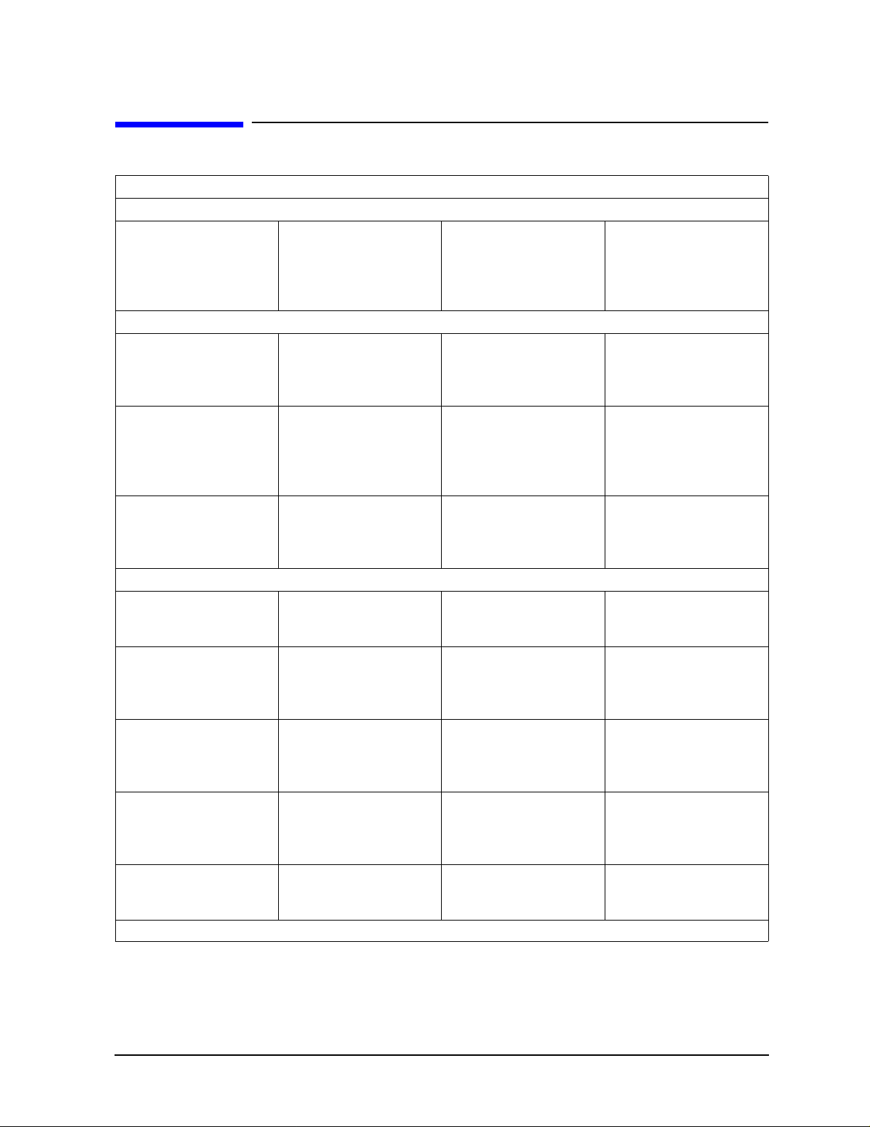
Table 2-1 Environmental Requirements
Parameter Required Values/Ranges
Temperature
Operating
Storage
Error-corrected range
Altitude
Operating < 4,500 meters (≈15,000 feet) Storage < 15,000 meters (≈50,000 feet)
Relative humidity Always non–condensing
Operating 0 to 80% (26 °C maximum dry bulb) Storage 0 to 90%
a. The temperature range over which the calibration standards maintain conformance to their
b. The allowable network analyzer ambient temperature dr ift during measurement calibra tion and
a
b
specifications.
during measurements when the network analyzer error correction is turned on. Also, the range
over which the network analyzer maintains its specified performance while correction is turned on.
+20 °C to +26 °C (+68 °F to +79 °F)
−40 °C to +75 °C (−40 °F to +167 °F)
±1 °C (1.8 °F) of measurement calibration temperature
Temperature—What To Watch Out For
Due to the small dimensions of the devices, electrical characteristics will change with
temperature. Theref ore, the operat ing temperature is a critical facto r in their performance ,
and must be stable before use.
IMPORTANT Avoid unnecess ary handling of the devices during use because your fingers
are a heat source.
2-2 85057B
Specifications
Mechanical Characteristics
Mechanical Characteristics
Mechanical characteristics such as center conductor protrusion and pin depth are not
warranted performance specifications. They are, however, important supplemental
characteristics related to elect rical performance. Agilent Technologies verifies the
mechanical characteristics of the devices in this kit with special gaging processes and
electrical testing. This ensures that the device connectors do not exhibit any improp er pin
depth when the kit leaves the factory.
“Gaging Connectors” on page 3-7 explains how to use gages to determine if the kit devices
have maintained their mechanical integrity. Refer to Table 2-2, “Connector Pin Depths,”
for allowable recession.
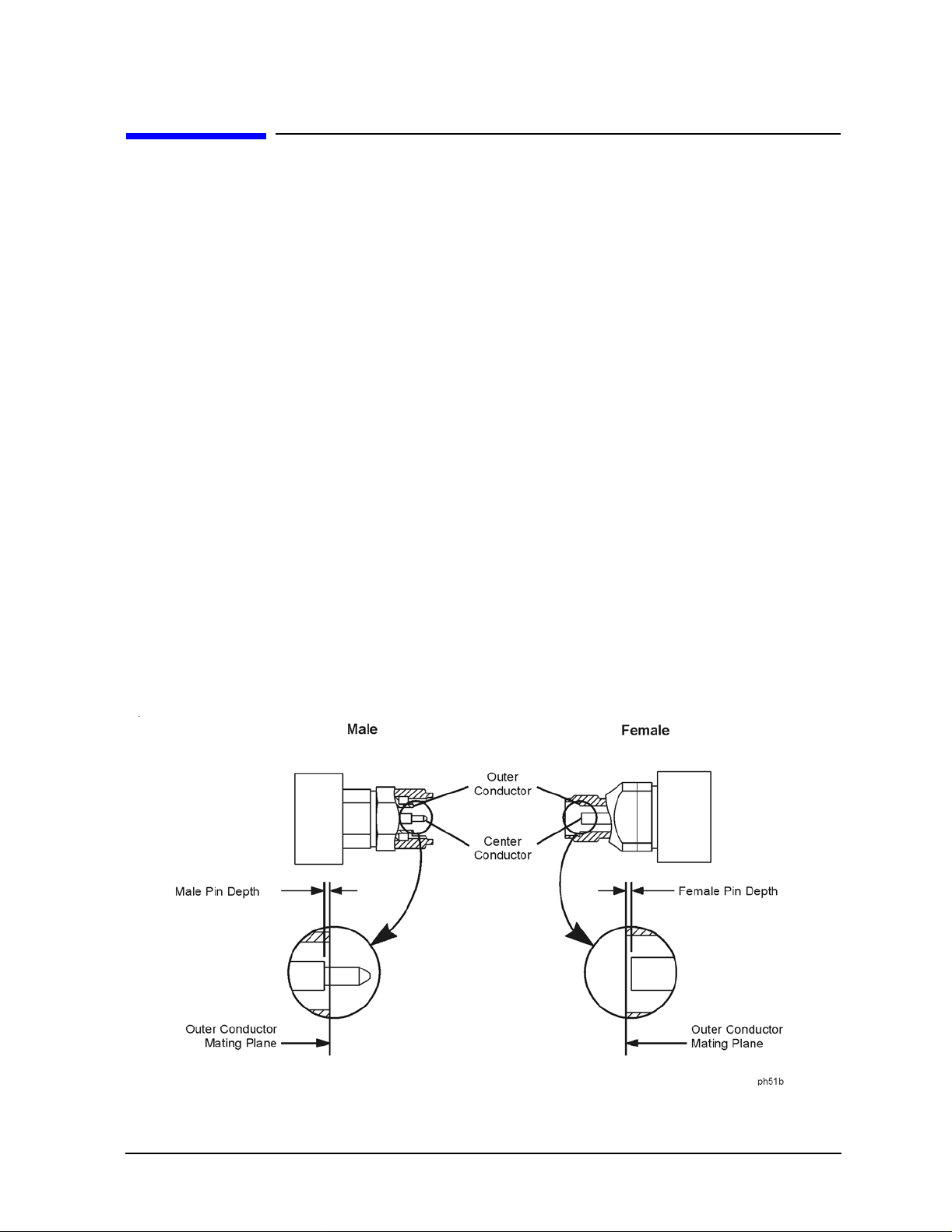
Pin Depth
Pin depth is the distance the center conductor mat ing plane differs from being flush with
the outer co n d uctor mati ng plane. See Figure 2-1. The pin depth of a connector can be in
one of two conditions:
• Protrusion is the condition in which the center conductor extends beyond the outer
conductor mating plane. This condition will indicate a positive value on the connector
gage.
• Recession is the condition in which the center conductor is set back from the outer
conductor mating plane. This condit ion will indicate a negative value on the connector
gage.
Figure 2-1 Connector Pin Depth
85057B 2-3
Specifications
Mechanical Characteristics
Supplemental Characteristics
The following tables list the dimensions of the 50Ω airline and the 25Ω mismatch airline.
These are supplemental mechanical char acteristics , and from these characteri stics you can
calculate expected electrical performance.
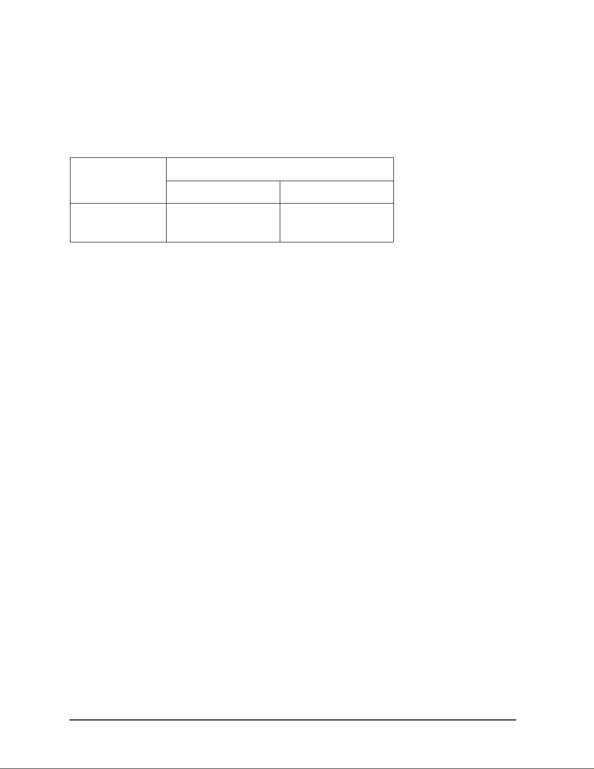
Table 2-2 Connector Pin Depths
Connectors
millimeters inches
Attenuators 0.000 to −0.025 0.0000 to −0.001 Airlines
a
a. The relationship between the length of the inner conductor and the
length of the outer conductor determines the airline center conductor
recession. Refer to “Gaging the Airline” on page 3-1 0.
0.0000 to −0.013 0.0000 to −0.0005
Allowable Recession
Using these mechanical dimensions , you can calculat e the expect ed elec trical pe rformance
with the equations in the following publications:
• Nelson, Robert E., and Marlene R. Coryell, "Electrical P arameters of Precisi on, Coaxial,
Air-Dielectric Transmission Lines", U.S. National Bureau of Standards Monograph No.
96.
• Somlo, P.I., "The Computation of Coaxial Line Step Capacitances", IEEE Transactions
on Microwave Theory and Techniques, Volume MTT-15, No. 1, J anuary, 1967.
The measurement method in these publications provides a general idea of the expected
device characteristic impedance. Variations in connector interface s can have a large effect
on your actual electrical measurements.
2-4 85057B

Specifications
Mechanical Characteristics
Airline Characteristics
The dimensions of the airline outer conductor are s hown in Figure 2-2. There are two similar outer conductors in each kit. They are specifically matched to each center conductor.
The dimensions of the 50Ω airline and the 25Ω mismatch airline are shown in Figure 2 -3
and Figure 2-4.
CAUTION The center and outer conductors of the airlines i n this kit have been
mechanically measured and matched. Do not use the center or oute r
conductors provided in th i s kit with a cent er or outer con ductor from an y
other airline. Damage to the airline or attaching connector may result.
Figure 2-2 Airline Outer Conductor
Dimension millimeters inches
D −Diameter 2.400 ±0.0025 0.0945 ±0.0001 L −Length
85057B 2-5
49.991 ±0.025
1.968 ±0.001

Specifications
Mechanical Characteristics
Figure 2-3 50Ω Airline Center Conductor
Dimension millimeters inches
d 1.0423 ±0.003 0.04104 ±0.00012
∆L +0.0025/−0.013 +0.0001/ −0.0005
Figure 2-4 25Ω Mismatch Airline Center Conductor
Dimension millimeters inches
d 1.0423 ±0.008 0.04104 ±0.0003
d
1
l
1
l
2
∆L +0.0025/−0.013 +0.0001/−0.0005
1.58 ±0.005 0.0622 ±0.0002
37.46 ±0.019 1.4748 ±0.0007
6.22 ±0.050 0.2449 ±0.002
2-6 85057B

Specifications
Electrical Specifications
Electrical Specifications
At the factory, each verification device is electrically characterized on a network analyzer
measurement system. These factory measur ements are tra ceable to t he Natio nal Institut e
of Standards and Technology (NIST) through mechanical and electrical paths (for more
information on traceability, contact Agilent Technologies. Refer to “Contacting Agilent” on
page 5-5.
The factory-measured data for each device is supplied in print and on disk with your kit.
85057B 2-7

Specifications
Electrical Specifications
2-8 85057B

3 Use, Maintenance, and Care of the
Devices
3-1

Use, Maintenance, and Care of the Devices
Electrostatic Discharge
Electrostatic Discharge
Protection against ESD (electrostatic discharge) is essential while connecting, inspecting,
or cleaning connectors attached to a static-sensitive circuit (such as those found in test
sets).
Static electricity can build up on your body and can easily damage sensitive internal
circuit elements when discharged. Static discharges too small to be felt can cause
permanent da mage. Devices such a s ca l i b ra t i on co mponents and devices unde r test
(DUTs), can also carry an el ec trostatic ch ar g e. To prevent dam a g e to th e test set,
components, and devices:
• always wear a grounded wrist strap having a 1 MΩ resistor in series with it when
handling components and devices or when making connections to the test set.
• always use a grounded, conductive table mat while making connections.
• always wear a heel strap when working in an area with a conductive floor. If you are
uncertain about the conductivity of your floor, wear a heel strap.
• always ground yourself before you clean, inspect, or make a connection to a
static-sensitive device or te st po rt. You can, for example , gras p the ground ed oute r shel l
of the test port or cable connector briefly.
• always ground the center conductor of a test cable before making a connection to the
analyzer test port or other static-sensitive device. This can be done as follows:
1. Connect a short (from your calibration kit) to one end of the cable to short the cent er
conducto r to th e ou ter conductor.
2. While wearing a grounded wrist strap, grasp the out er shell of the cable connector.
3. Connect the other end of the cable to the test port.
4. Remove the short from the cable.
Figure 3-1 shows a typical ESD protection set up using a grounded mat and wrist strap. F or
parts numbers of ESD protection supplies, refer to Table 6-2
Figure 3-1 ESD Protection Setup
3-2 85057B

Use, Maintenance, and Care of the Devices
Visual Inspection
Visual Inspection
Visual inspection and, if necessary, cleaning should be done every time a connection is
made. Metal particles from the connector threads may fall into the connector when it is
disconnected.
CAUTION Devices with damaged connectors should be immediately discard ed or c learly
marked and set aside for repair. A damaged device will in turn damage any
good connector to which it is attached. Determine the cause of the damage
before connecting a new, undamaged connector in the same configuration.
In some cases, magnification is necessary to see damage to a connector; a magnifying
device with a magnification of ≥ 10× is recommended. However, not all defects that are
visible only under magnification will affect the electr ical performance of the conne ctor. Use
the following guidelines when evaluating the integrity of a connector.
Look for Obvious Defects and Damage First
Examine the connectors first for obvious defects or damage: badly worn plating on the
connector interface, deformed threads or bent, broken, or misaligned center conductors.
Connector nuts should move smoothly and be free of burrs, loose metal particles, and
rough spots.
What Causes Connector Wear?
Connector wear is caused by connecting and disconnecting the devices. The more use a
connector gets, the fas ter it wears and degrades. The wear is greatly accelerated when
connectors are not kept clean, or are not connected properly.
Connector wear eventually degrades performance of the device. Calibration devices should
have a long life if their use is on the order of a few times per week. Replace de vices with
worn conne c to rs.
The test port connect ors on t he network analyzer test s et may ha ve many connections each
day, and are, therefore, more subject to wear. It is recommended that an adapter be used as
a test port saver to minimize the wear on the test set’s test port connectors.
Inspect the Mating Plane Surfaces
Flat contact between the connectors at all points on their mating pl ane surfaces is required
for a good connection. See Figure 2-1 on page 2-3. Lo ok especiall y fo r de e p scratches or
dents, and for dirt and metal particles on the connector mating plane surfaces. Also look
for signs of damage due to excessive or uneven wear or misalignment.
Light burnishing of the mating plane surfaces is normal, and is evident as light scratches
or shallow circular marks distributed more or less uniformly over the mating plane
surface. Other small defects and cosmetic imperfections are also normal. None of these
affect electrical or mechanical performance. If a connector shows deep scratches or dents,
particles clinging to the mating plane surfaces, or uneven wear, clean and inspect it again.
85057B 3-3

Use, Maintenance, and Care of the Devices
Visual Inspection
Inspect Female Connectors
Inspect the contact fingers in the female center conductor carefully. These can be bent or
broken, and damage to them is not always easy to see. A connector with damaged contact
fingers will not make good electrical contact an d must be replaced.
NOTE This is particularly important when mating nonprecision to precision devices.
The female connectors in this calibration kit are metrology-grade, precision slotless
connectors (PSC). Precision slot less female connectors are used to improve accuracy. With
PSCs on test ports and standards, the accuracy achieved when measuring at 50 dB return
loss levels is comparable to using conventional slotted connectors measuring devices
having only 30 dB return loss. This represent s an accurac y improvement of appr oximately
10 times.
Conventional female center conductors are slotted and, when mated, are flared by the
male pin. Because physical dimensions determine connecto r impedance, this change in
physical dimension affects electrical perfo rmance, making it very difficult to perform
precision measurements with conventional slotted female connectors.
The precision slotless connector was developed to eliminate this problem. The PSC has a
center conductor with a solid cylindrical she ll, the outside diameter of which does not
change when mated. Instead, this center conductor has an internal contact that flexes to
accept the male pin.
3-4 85057B

Use, Maintenance, and Care of the Devices
Cleaning Connectors
Cleaning Connectors
1. Use Compressed Air or Nitrogen Clean connectors are essential for ensuri ng the integrity of RF and microwave coaxial
connections.
WARNING Always use protective eyewear when using compressed air or
nitrogen.
Use compressed air (or nitrogen) to loosen particles on the connector mating plane surfaces.
You can use any source of clean, dry, low-pressure compressed air or nitrogen that has
an effective oil-vapor filter and liquid cond ensation trap placed just before the outlet
hose.
Ground the hose nozzle to prevent electrostatic discharge, and set the air pressure to
less than 414 kP a (60 psi) to control t he velocity of the air st ream. High-velocity st reams
of compressed air can cause electrostatic effects when directed into a connector. These
electrostatic effect s can damage the device. Refer to “Electrostatic Discharge” on
page 3-2 for additional information.
2. Clean the Connector Threads
WARNING Keep isopropyl alcohol away from heat, sparks, and flame. Store in a
tightly closed container . It is extremely flammable. In case of fire, use
alcohol foam, dry chemical, or carbon dioxide; water may be
ineffective.
Use isopropyl alcohol with adequate ventilation and avoid contact
with eyes, skin, and clothing. It caus es skin ir ritati on, may cause eye
damage, and is harmful if swallowed or inhaled. It may be harmful if
absorbed through the skin. Wash thoroughly after handling.
In case of spill, soak up with sand or earth. Flush spill area with water.
Dispose of isopropyl alcohol in accordance with all applicable
federal, state, and local environmental regulations.
Use a lint-free swab or cleaning cloth moistened with isopropyl alcohol to remove any
dirt or stubborn contaminants on a connector that cannot be removed with compressed
air or nitrogen. Refer to Table 6-2 on page 6-4 for p art numbers for iso propyl alcohol and
cleaning swabs.
a. Apply a small amount of isopropyl alcohol to a lint-free cleaning swab.
b. Clean the connecto r th reads.
85057B 3-5

Use, Maintenance, and Care of the Devices
Cleaning Connectors
c. Let the alcohol evaporate, then blow the threads dry with a gentle stream of clean,
low-pressure compressed air or nitrogen. Always completely dry a connector before
you reassemble or use it.
3. Clean the Mating Plane Surfaces a. Apply a small amount of isopropyl alcohol to a lint-free cleaning swab.
b. Clean the center and outer conductor mating plane surfaces. Refer to Figure 2-1 on
page 2-3. When cleaning a female connector, avoid snagging the swab on the center
conductor contact fingers by using short strokes.
c. Let the alcohol evaporate , then bl ow the connec tor dr y with a ge ntle stream of c lean,
low-pressure compressed air or nitrogen. Always completely dry a connector before
you reassemble or use it.
4. Inspect the Connector
Inspect the connector t o ma ke s ure that no pa rtic l es or resi due remain. Refe r to “Visual
Inspection” on page 3-3.
3-6 85057B

Use, Maintenance, and Care of the Devices
Gaging Connectors
Gaging Connectors
The gages available from Agilent Technologies are intended for pre v entive maintenance
and troubleshooting purposes only. They are effective in detecting excessive center
conductor protrusion or recession, and conductor damage on DUTs, test accessories, and
the calibrat i on ki t devices. Do not use the gages for precise pin depth measurements.
Connector Gage Accuracy
The connector gages are only capable of performing coarse measurements. They do not
provide the degree of accuracy necessary to pr ecisely measure the pin depth of the kit
devices. This is partial ly due to the repeatability unc ertainties that are associated with the
measurement. Only the factory—through special gaging processes and electrical testing—
can accurately verify the mechanical characteristics of the devices.
With proper technique, the gages are useful in detecting gross pin depth errors on device
connectors. To achieve maximum accuracy, random errors must be reduced by taking the
average of at least three measurements having different gage orientations on the
connector. Even then, the resultant average can be in error by as much as ±0.0001 inch due
to systematic (biasing) errors usually resulting from worn gages and gage masters. As the
gages undergo more use, the systematic error s can become more si gnificant in the ac curacy
of the measurement.
NOTE When measuring pin depth, the measured value (resultant av erage of three
or more measurements) contains measurement uncertainty and is not
necessarily the true value. Always compare the measured value with the
observed pin depth limits (which account for measurement uncertainties) in
Table 2-2 on page 2-4 to evaluate the conditi on of devic e connectors.
When to Gage Connectors
Gage a connector at the following times:
• Prior to using a device for the first time, record the pin depth measurement so that it
can be compared with future readings. This serves as a good troubleshooting tool when
you suspect damage may have occurred to the device.
• If either visual inspection or electrical performance suggests that the connector
interface m ay b e ou t of typical ra n g e (d u e to w ear or damag e, fo r example) .
• If a verification device is used by someone else or on another system or piece of equipment.
• Initially, after every 100 connections, and after that, as often as experience indicates.
85057B 3-7

Use, Maintenance, and Care of the Devices
Gaging Connectors
Gaging Procedures
Gaging 2.4 mm Connectors
NOTE Always hold a connector gage by the gage barrel, below the dia l indicator.
This gives the best stability, and improves measurement accuracy. (Cradling
the gage in your hand or holding it by the dial applies stress to the gage
plunger mechanism through the dial indicator housing.)
1. Select the proper gage for your connector. The gages are intended for performing
2.4 mm pin depth measurements. Refer to Table 6-2 on page 6-4 for gage part numbers.
2. Inspect and clean the gage, gage master, and device to be gaged. Refer to “Visual
Inspection” and “Cleaning Connector s” earlier in th i s chapter.
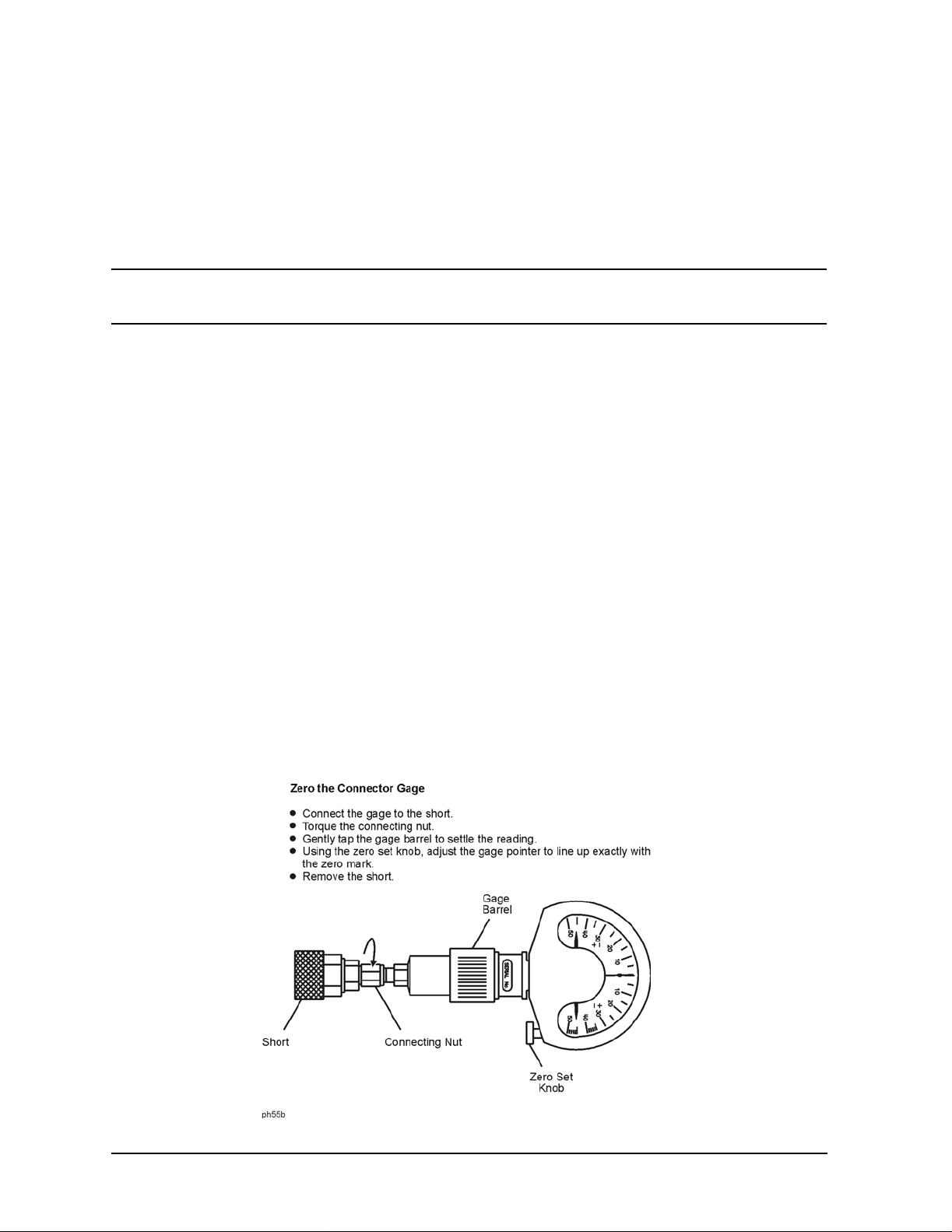
3. Zero the connector gage (refer to Figure 3-2): a. While holding the gage by the barrel, and without turning the gage or the device,
connect the gage to the gage master by interconnecting the male and female
connectors. Connect the nut finger tight. Do not overtighten.
b. Using an open-end wrench to keep the device body from rotating, use the torque
wrench included in the kit to tighten the connecting nut to the specified torque. Refer
to “Final Connection Using a Torque Wrench” on page 3-14 for additional
information.
c. As you watch the gage pointer, gently tap the barrel of the gage to settle the reading.
The gage pointer should line up exactly with the zero mark on the gage. If not, adjust
the zero set knob until the gage pointer lines up exactly with the zero mark.
d. Remove the gage master.
4. Gage the device connector (refer to Figure 3-2): a. While holding the gage by the barrel, and without turning the gage or the device,
connect the gage to the device by interconnecting the male and female connectors.
Connect the nut finger-tight. Do not overtighten.
b. Using an open-end wrench to keep the device body from rotating, use the torque
wrench included in the kit to tighten the connecting nut to the specified torque. Refer
to “Final Connection Using a Torque Wrench” on page 3-14 for additional
information.
c. Gently tap the barrel of the gage with your finger to settle the gage reading .
d. Read the gage indicator dial. Read only the black ± signs, not the red ± signs.
For maximum accuracy, measure the connector a minimum of three times and take
an average of the readings. After each measurement, rotate the gage a quarter-turn
to reduce measurement variations that result from the gage or t he connector face no t
being exactly perpendicular to the center axis.
e. Compare the average reading with the specifications listed in Table 2-2 on page 2-4.
f. Without turnin g th e g a g e o r th e de v i c e, rem o v e th e device from th e gag e.
3-8 85057B

Figure 3-2 Gaging 2.4 mm Connectors
Use, Maintenance, and Care of the Devices
Gaging Connectors
85057B 3-9
Use, Maintenance, and Care of the Devices
Gaging Connectors
Gaging the Airline
The airlines in this kit are measured and matched for length at the factory using special
fixtures and gages. Because the gages supplied in the calibration kits do not have the
accuracy of the factory gages, use the following procedure for very general results only.
Perform this procedure whenever you suspect that a center conductor has been switched
with another airline or that a device has been damaged.
NOTE Always hold a connector gage by the gage barrel, below the dia l indicator.
This gives the best stability, and improves measurement accuracy.
1. Select a male connector gage and male short for this procedure. Refer to T able 6-2 on
page 6-4 for part numbers.
2. Inspect and clean the mating surfaces and connector thread s of the short, airline, and
gage. Refer to “Visual Inspection” and “Cleaning Connectors” earlier in this chapter.
3. Zero the connector gage (refer to Figure 3-3): a. While holding the gage by the barrel and without turning the gage or the short,
connect the gage to the short by interconnecting the male and female connectors.
Connect the nut finger tight. Do not overtighten.
b. Using an open-end wrench to keep the device body from rotating, use the torque
wrench reco m mended for us e w it h th i s ki t to tighten th e connecting n u t to the
specified torque. Refer to “Final Connection Using a Torque Wrench” on page 3-14 for
additional information.
c. As you watch the gage pointer, gently tap the barrel of the gage to settle the reading.
d. The gage pointer should line up exact ly with the zero mark on the gage. If not, loosen
the dial lock screw on the gage and rotate the gage dial so that the pointer is aligned
with the zero mark. Tighten the dial lock screw.
e. Without turning the short or the gage, remove the short from the gage . Refer to “How
to Separate a Connection” on page 3-18.
Figure 3-3 Zeroing the Connector Gage Using the Short
3-10 85057B

Use, Maintenance, and Care of the Devices
Gaging Connectors
4. Assemble the airline and center conductor (refer to Figure 3-4 ):
CAUTION W ear gloves while performing the following steps. You will be touching the
exposed center conductor of the airline. Do not transfer oil or dirt from your
fingers to the center conductor. See “Handling and Storage” on page 3-18.
a. Remove the center conductor from its pl astic case. Make sure you select the corre ct
center conductor for the airline you are connecting. Refer to Figure 2-3 and
Figure 2-4 on page 2-6 for illustrations of both center conductors.
b. Remove the protective end cap from the female end (the end withou t the connecting
nut) of the outer conductor.
c. Leave the protective end cap on the male end of the airline to prevent the center
conductor from falling out of the outer conductor.
d. Insert the center conductor into the outer conductor so that the female end of the
center cond uctor is toward t he fe m a l e en d of th e outer cond u ctor (the end w i th o u t
the connect o r n u t). Refer to Fig ure 3-4.
Figure 3-4 Assembling the Airline and Center Conductor
5. Attach the short: a. Without turning the airline or the shor t, connect the airline to the short by
interconnecting the male and female connectors . Connect the nut finger tight. Do not
overtighten.
b. Using an open-end wrench to keep the device body from rotating, use the torque
wrench reco m mended for us e w it h th i s ki t to tighten th e connecting n u t to the
specified torque. Refer to “Final Connection Using a T orque Wrench” on page 3-14 for
additional information.
c. Remove the protective end cap from the male end of the airline.
85057B 3-11

Use, Maintenance, and Care of the Devices
Gaging Connectors
NOTE Do not allow either the center or outer conductor of the airline to come in
contact with a metal or harder surf ace . The soft gold p lating can be displaced,
changing the pin depth and thus the performance of the airline.
d. Carefully press the male end o f the ce nter conduc tor l ightly against a f irm flat ob ject
to seat the center conductor into the short.
6. Gage the airline (refer to Figure 3-5): a. While holding the gage by the barrel, and without turning the gage or the airline,
connect the gage to the airline by interconnecting the male and female connectors.
Connect the nut finger tight. Do not overtighten.
b. Using an open-end wrench to keep the device body from rotating, use the torque
wrench reco m mended for us e w it h th i s ki t to tighten th e connecting n u t to the
specified torque. Refer to “Final Connection Using a Torque Wrench” on page 3-14 for
additional information.
c. Gently tap the barrel of the gage with your finger to settle the gage reading .
Figure 3-5 Gaging the Airline
d. Wait approximately 5 minutes for the temperature to stabilize. Do not touch the
airline, short, or gage during this time as your body temperature will affect the
temperature of the devices.
The gage reading should be within the pin depth specifications listed in T able 2-2 on
page 2-4. Remember, the gage is intended for coarse measurements only and has an
accuracy of ±0.0001 in.
3-12 85057B

Use, Maintenance, and Care of the Devices
Gaging Connectors
7. Disconnect the short and gage from the airline:
NOTE If the airline center conductor does not disengage from the device center
conductor, gently pull the center conductors apart and then push the airline
center conductor back inside the outer conductor of the airline.
a. Without tu rn i n g th e ai r l i ne o r th e gage, remove th e g a g e fr o m th e ai rline. Refer to
“How to Separate a Connection” on page 3-18.
b. Replace the protective end cap on the airline to prevent the center conductor from
sliding out of the outer conductor.
c. Without turning the airline or the short, remove the short from the airline. Refer to
“How to Separate a Connection” on page 3-18.
d. If you will not be using the airline again immediately, slide the center conductor out
of the outer conductor and store the center conductor in the plastic case provided.
e. Replace the other protective end cap on the outer conductor and store the center and
outer conductors in the foam lined storage case.
85057B 3-13

Use, Maintenance, and Care of the Devices
Connections
Connections
Good connections require a skilled opera tor. The most common cause of measu rement error is bad connections. The following procedures illustrate how to make good connections.
How to Make a Connection
Preliminary Connection
1. Ground yourself and all devices. Wear a grounded wrist strap and work on a grounded,
conductive table mat. Refer to “Electrostat ic Discharge” on page 3-2 for ES D
precautions.
2. Visually in s p e c t the connect o rs. R ef e r to “Visual Insp e c ti on” on page 3-3.
3. If necessary, clean the connectors. Refer to “Cleaning Connec tors ” on page 3-5.
4. Use a connector gage to verif y that all cente r conductors are wit hin the pin dept h values
listed in Ta ble 2-2 on page 2-4. Refer to “Gaging Connectors” on page 3-7.
5. Carefully align the connectors. The male connector center pin must slip concentrically
into the contact finger of the female connector.
6. Push the connectors straight together and tighten the connector nut finger tight.
CAUTION Do not turn the device body. Turn only the connector nut. Damage to the
center conductor can occur if the device body is rotated.
Do not twist or screw the connectors together. As the center conductors mate, there is
usually a slight resistance.
7. The preliminary connection is tight enough when the mating plane surfaces make
uniform, light contact. Do not overtighten this connection.
A connection in which the outer conductors make gentle contact at all points on both
mating surfaces is sufficient. Very light finger pressure is enough to accomplish this.
8. Make sure the connectors are properly supported. Relieve any side pressure on the
connection from long or heavy devices or cables.
Final Connection Using a Torque Wrench
Use a torque wrench to make a final connection. Table 3-1 provides information about the torque wrench recommended for use with the calibration kit. A torque wrench is not included in the calibration kit. Refer to Table 6-2 on page 6-4 for pa rt number an d orderi ng information.
Table 3-1 Torque Wrench Information
Connector Type Torque Setting Torque Tolerance
2.4 mm 90 N-cm (8 in-lb) ±9.0 N-cm (±0.8 in-lb)
3-14 85057B

Use, Maintenance, and Care of the Devices
Connections
Using a torque wrench guarantees that the c onnec tion is no t too tight , prevent ing pos sible
connector damage. It also guarantees that all connections are equally tight each time.
Prevent the rotation of anything other than the connect or nut that you are tightening. It
may be possible to do this by hand if one of the connectors is fixed (as on a test port).
However, it is recommended that you use an open-end wrench to keep the body of the
device from turning.
1. Position both wrenches within 90 degrees of each other before applying force. See
Figure 3 -6. Wrenches opposing each other (greater than 90 degrees apart) will cause a
lifting action which can misalign and stress the connections of the devices involved.
This is especially true when several devices are connected together.
Figure 3-6 Wrench Positions
2. Hold the torque wrench lightly, at the end of the handle only (beyond the groove). See
Figure 3 -7.
Figure 3-7 Using the Torque Wrench
3. Apply downward force perpendicular to the wrench handle. This applies torque to the
connection through the wrench.
Do not hold the wrench so tightly that you push the handle straight down along its
length rather than pivoting it, otherwise , you apply an unknown amount of torque.
85057B 3-15

Use, Maintenance, and Care of the Devices
Connections
CAUTION You don’t have to fully break the handle of the torque wrench to reach the
specified torque; doing so can cause the handle to kick back and loosen the
connection. Any give at all in the handle is sufficient torque.
4. Tighten the connection just to the torque wrench break point. The wrench handle gives
way at its internal pivot point. See Figur e 3 - 7 . Do not tighten the connection further.
Connecting the Airline
CAUTION Before making any connections to the test set, be sure that bias power to the
test set is off, and tak e ca r e to avoid electro static discha r g e. Refe r to
“Electrostatic Discharge” on page 3-2.
CAUTION W ear gloves while performing the following procedure. You will be touching
the exposed center conductor of the airline. It is important that you do not
transfer oil and dirt from your fingers to this center conductors. Refer to
“Handling and Storage” on page 3-18.
Before makin g th e connectio n, refer to “Preliminary Connection” on page 3-14. Cables with the appropriate adapters on the ends should be connected to PORT 1 and
PORT 2 of the network analyzer.
1. Remove the center conductor from its pl astic case. Make sure you select the corre ct
center conductor for the airline you are connecting. Refer to Figure 2-3 and Figure 2-4
on page 2-6 for illustrations of both center conductors.
2. Remove the protective end cap from the female end (the end without the connecting
nut) of the airline. Leave the pr otective end cap on th e male end of the airl ine to preve nt
the center conductor from falling out of the outer conductor.
3. Insert the female end of the center conductor into the outer conductor so that the female
end of the center conductor is toward the female end of the outer conductor (the end
without the connector nut).
Figure 3-8 Airline Center Conductor Placement
3-16 85057B

Use, Maintenance, and Care of the Devices
Connections
NOTE To avoid damaging the airline center conductor, always keep it in direct line
with the center conductor of the device to which it is being connected.
4. Bring the airline—with center conductor install ed—toward the cable connector and
mate the female end of the airline center conductor with the center conductor of the
cable connector. Refer to Figure 3-9.
Figure 3-9 Connecting the Airline
5. Push the airline's female coupling sleeve forward and turn the connecting nut (of the
adapter attached to the cable) to mate the outer conductor of the airline with the
adapter. Connect the nut finger tight. Do not overtighten.
6. Remove the protective end cap from the male end of the airline. Align and insert the
male end of the airline center conductor into the female end of the cable adapter and
mate the outer conductors. Connect the nut finger tight. Do not overtighten.
7. Using an open-end wrench, hold the sliding female coupli ng sleeve on t he female end of
the outer conductor to keep it from rotating. Refer to Figure 3-10 Use the torque wrench
recommended for use with this kit to tig hten the adapter connect ing nut to the specified
torque. Refer to “Final Connection Using a Torque Wrench” on page 3-14.
8. Using an open-end wrench to keep the cable adapter from rotating, use the torque
wrench reco m mended for us e w it h th i s ki t to tighten th e airline male-end conn ec ting
nut to the spec i fi ed torque.
Figure 3-10 Torquing the Connections
85057B 3-17

Use, Maintenance, and Care of the Devices
Handling and Storage
How to Separate a Connection
NOTE Do not turn the device body. Only turn the connector nut. Damage to the
center conductor can occur if the device body is rotated.
1. Use an open-end wrench to prevent the de vi ce body from turning.
2. Use another open-end wrench to loosen the connector nut.
3. Complete the disconnection by hand, turning only the connector nut.
4. Pull the connectors straight apart withou t twisting, rocking , or bending either of the
connectors.
NOTE If disconnecting an airline and the airline center conductor does not
disengage from the device center conductor, gently pull the center conductors
apart and the n p u sh th e ai rline center conducto r back inside th e o u ter
conducto r of the airlin e.
Handling and Storage
• Do install the protective end caps and store the devices in the foam-lined storage case
when not in use.
• Do keep connectors and airlines clean.
• Do not store connectors and airlines loose in a box, or in a desk or bench dr aw er. This is
the most common cause of connector damage during storage.
• Do not touch mating plane surfaces. Natural skin oils and microscopic particles of dirt
are easily transferred to a connector inte rface and are very difficult to remove.
• Do not set connectors contact-end down on a hard surface. The plating and the mating
plane surfaces can be damaged if the interface comes in contact with any hard surface.
3-18 85057B

4 Performance Verification
4-1

Performance Verification
Introduction
Introduction
The performance of your verification kit can only be verified by returning the kit to Agilent
Technologies for recertification. The equipment required to verify the specifications of the
devices in the kit has been specially manufactured and is not commercially available.
How Agilent Verifies the Devices in Your Kit
Agilent verifies the specifications of these devices as follows:
1. The residual microwav e error terms of the test system are verified with precision
airlines and shorts that are directly traced to the National Institute of Standards and
Tec hnology (NIST). The airline and short charact eristics are developed from mechanical
measurements. The mechanical measurements and material properties are carefully
modeled to give very accurate electrical representation. The mechanical me asurements
are then traced to NIST through various plug and ring gages and other mechanical
measurements.
2. Each device is electrically tested on this system. For the initial (before sale) testing of
the devices, Agilent includes the test measurement uncertainty as a guardband to
guarantee each device meets the published specification. For recertifications (after
sale), no guardband is used and the measured data is compared directly with the
specification to determine the pass or fail status. The measurement uncertainty for
each device is, however, recorded in the calibration report that accompanies recertified
kits.
These two steps establish a traceable link to NIST for Agilent to the extent allowed by the
institute’s calibration facility. The specifications data provided for the devices in the kit is
traceable to NIST through Agilent Technologies.
4-2 85057B

Performance Verification
Recertification
Recertification
The following will be provided with a recertified kit:
• a new calibrat i on st i cke r a ff i x e d to th e ca se
• a certificate of calibration
• a calibration report for each device in the kit listing measured values, specifications,
and uncertainties
NOTE A list of NIST traceable numbers may be purchased upon request to be
included in the calibration report.
Agilent Te chnologies offers a Standard calibration for the recertification of the kit. For more information, contact Agilent Technologies. Refer to “Contacting Agilent” on page 5-5.
How Often to Recertify
The suggested initial interval f or recertifica tion is 12 months or sooner. The actual need for
recertification depends on the use of the kit. After reviewing the results of the initial
recertification, you may establi sh a differ ent rec ertificatio n interval that r eflects t he usage
and wear of the kit.
NOTE The recertification interval should begin on the date the kit is first used after
the recerti fi c at i on date.
Where to Send a Kit for Recertification
Contact Agilent T echnologies for information on where to send your kit for recertif ication. Refer to “Contacti n g A g i le n t” o n page 5-5. Refer to “Returning a Kit or Device to Agilent
Technologies” on page 5-4 for details on sending your kit.
85057B 4-3

Performance Verification
Recertification
4-4 85057B

5 Troubleshooting
5-1

Troubleshooting
Troubleshooting Process
Troubleshooting Process
If your network analyzer does not pass performance verification, follow the steps in
Figure 5-1 to determine the cause of the failure and the c orrect act ion to t ake to cor rect th e
failure.
5-2 85057B
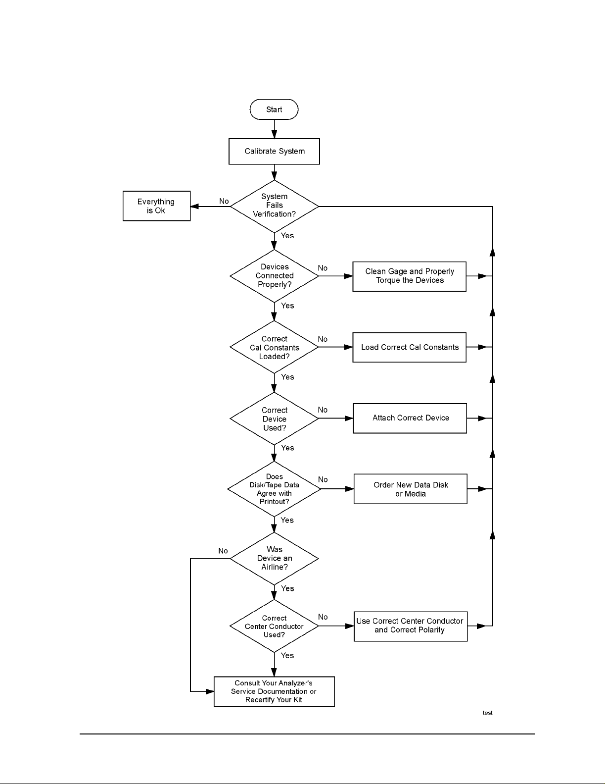
Figure 5-1 Troubleshooting Flowchart
Troubleshooting
Troubleshooting Process
85057B 5-3

Troubleshooting
Returning a Kit or Device to Agilent Technologies
Returning a Kit or Device to Agilent Technologies
If your kit or device requires service , contact Agilent Tec hnologies for information on
where to send it. See “Contact i n g Agilent” on pa g e 5 -5 for information. Include a service
tag (located at the back of this manual) on which you provide the followi ng information:
• your company name and address
• a technical contact person within your comp any, and the person's complete telephone
number including country code and area code
• the model number and serial number of the kit (if returning a complete kit)
• the part number and serial number of each device being returned
• the type of serv i ce re q u i red
•a detailed description of the problem (if applicable) and how the device was being used
when the problem occurred
5-4 85057B
Contacting Agilent
Online assistance: www.agilent.com/find/assist
Americas
Brazil
(tel) (+55) 11 3351 7012
(fax) (+55) 11 3351 7024
Australia
(tel) 1 800 225 574
(fax) 1 800 681 776
(fax) 1 800 225 539
Japan (Bench)
(tel) 0120 421 345
(alt) (+81) 426 56 7832
(fax) 0120 01 2144
Canada
(tel) +1 877 894 4414
(alt) +1 303 662 3369
(fax) +1 800 746 4866
Asia Pacific and Japan
China
(tel) 800 810 0189
(fax) 800 820 2816
Japan (On-Site)
(tel) 0120 421 345
(alt) (+81) 426 56 7832
(fax) 0120 012 114
Mexico
(tel) 1800 254 2440 Ext 2703
(alt) from USA 18008374039
(fax) 1 800 254 422
Hong Kong (tel) 800 933 229 (fax) 800 900 701
Malaysia
(tel) 1800 880 399
(fax) 1800 801 054
Troubleshooting
Contacting Agilent
United States
(tel) 800 829 4444
(alt) (+1) 303 662 3998
(fax) 800 829 4433
India
(tel) 1600 112 626
(alt) +65 6275 0800
(fax) 1600 113 040
New Zealand
(tel) +64 4 939 0635
(alt) 0800 738 378
(fax) +64 4 972 5364
Singapore
(tel) 1 800 275 0880
(fax) (+65) 6755 1214
South Korea
(tel) 080 778 0011
(fax) 080 778 0013
Taiwan
(tel) 0800 047 669
(fax) 0800 047 667
(fax) +886 3492 0779
Thailand
(tel) +66 2 267 5913
(tel) 1 800 2758 5822
(fax) 1 800 653 336
Europe
Austria
(tel) 0820 87 44 11*
(fax) 0820 87 44 22
France
(tel) 0825 010 700*
(fax) 0825 010 701*
Italy
(tel) (+39) (0)2 9260 8484
(fax) (+39) (0)2 9544 1175
Spain
(tel) (+34) 91 631 3300
(fax) (+34) 91 631 3301
Switzerland (Italian)
(tel) 0800 80 5353 opt. 3*
(fax) (0) 22 567 5314
(tel) = primary telephone number; (alt) = alternate telephone number; (fax) = FAX number; * = in country number
Belgium
(tel) (+32) (0)2 404 9340
(fax) (+32) (0)2 404 9395
Germany
(tel) 01805 24 6333*
(fax) 01805 24 6336*
Luxemburg
(tel) (+32) (0)2 404 9340
(fax) (+32) (0)2 404 9395
Sweden
(tel) 0200 88 22 55*
(alt) (+46) (0)8 5064 8686
(fax) 020 120 2266*
United King dom
(tel) (+44) (0)7004 666666
(fax) (+44) (0)7004 444555
Denmark
(tel) (+45) 7013 1515
(fax) (+45) 701 3 1555
Ireland
(tel) (+353) 1 890 924 204
(fax) 1 890 924 024
Netherlands
(tel) (+31) (0)20 547 2111
(fax) (+31) (0)20 547 2190
Switzerland (French)
(tel) 0800 80 5353 opt. 2*
(fax) (0) 22 567 5313
Finland
(tel) (+358) (0) 10 855 2100
(fax) (+358) (0) 10 855 2923
Israel
(tel) (+972) 3 9288 504
(alt) (+972) 3 9288 544
(fax) (+972) 3 9288 520
Russia
(tel) (+7) 095 797 3963
(alt) (+7) 095 797 3900
(fax) (+7) 095 797 3901
Switzerland (German )
(tel) 0800 80 5353 opt. 1*
(fax) 0 44 272 7373
8/10/05
85057B 5-5

Troubleshooting
Contacting Agilent
5-6 85057B

6 Replaceable Parts
6-1
Replaceable Parts
Introduction
Introduction
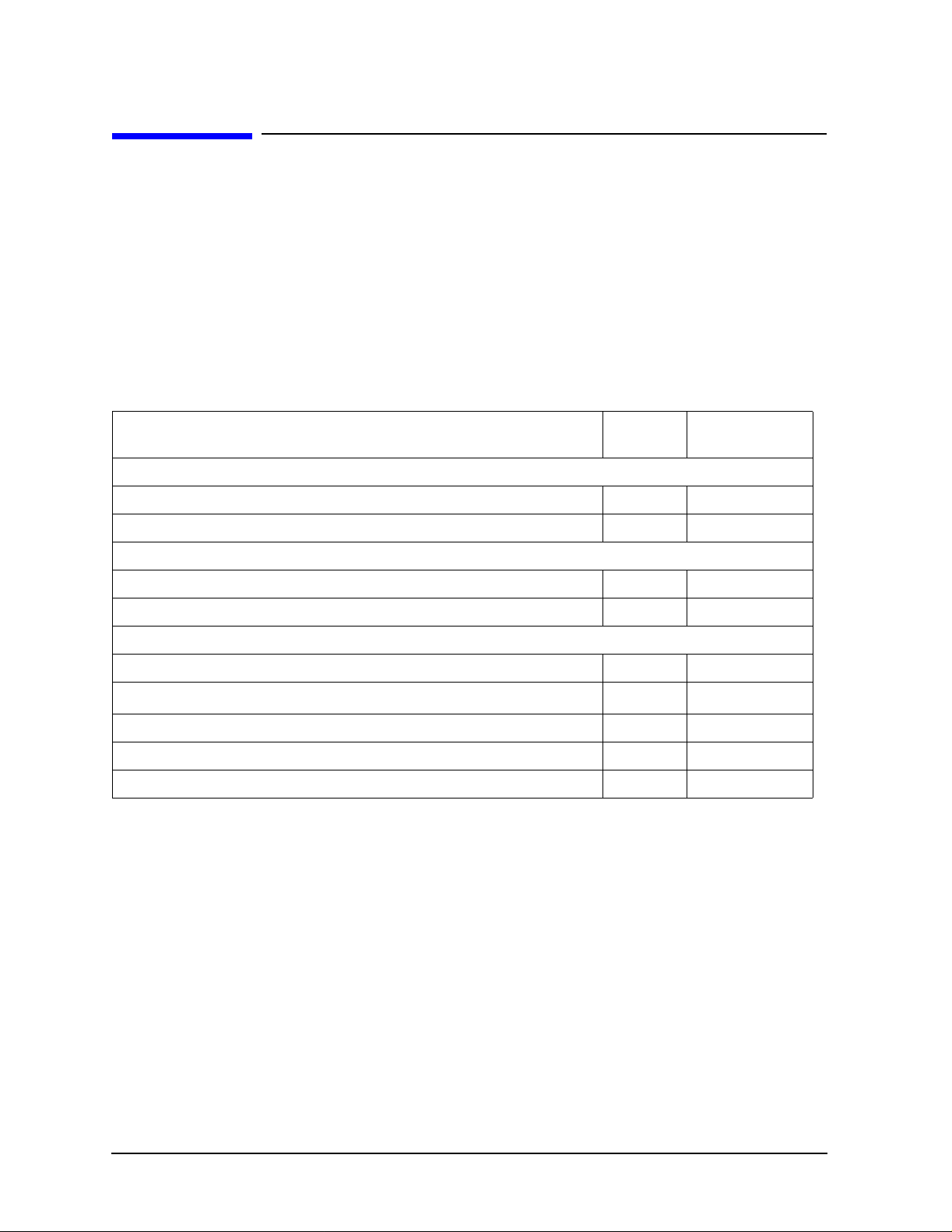
Tabl e 6- 1 lists the re plac ement p art numbers f or items incl uded i n the 85057B veri ficati on
kit and Figure 6 -1 illustrates the attenuators and airlines.
Table 6-2 lists the replacement part numbers for items not included in the verification kit
that are either required or recommended for successful operation of the kit.
To order a listed part, note the description, the part number, and the quantity desired.
Telephone or send your order to Agilent Technologies. See “Contacting Agilent” on
page 5-5.
Table 6-1 Replaceable Parts for the 85057B 2.4 mm Verification Kit
Description Qty
Per Kit
Attenuators
20 dB attenuator with data 1 85057-60010 40 dB attenuator with data 1 85057-60011
Airlines
50Ω airline with data 1 85057-60008 25Ω mismatch airline with data 1 85057-60009
Miscellaneous Items
Storage box assembly 1 85057-60003 User’s and service guide
Verification data disk (8510) 1 85057-60012 Verification data disk (8719, 8720, and 8722 Series) 1 85057-60014 Verification data disk (PNA Series) 1 85057-10005
a. Refer to See “Printing Copies of This Document” on page iii.
a
1 85057-90015
Agilent
Part Number
6-2 85057B

Figure 6-1 Component Identification Sheet for the 85057B
Replaceable Parts
Introduction
85057B 6-3

Replaceable Parts
Introduction
Table 6-2 Items Not Included in the Verification Kit
Description Qty Agilent
Connector Gages (2.4 mm)
Male connector gage set
Female connector gage set
Short (for gaging airlines)
a
a
a
Wrenches
Part Number
1 11752-60108 1 11752-60107 1 85056-60020
20 mm,
5/16 in, 9 0N-cm (8 in- lb) torque
90N-cm (8 in-lb) torque 1 8710-1764
a
1 8710-1765
5/16 in, open-end wrench 1 8720-0015 Spanner wrench 1 08513-20014
ESD Protection Devices
Grounding wrist strap 1 9300-1367 5 ft grounding cord for wrist strap 1 9300-0980 2 x 4 ft conductive table mat and 15 ft ground wire 1 9300-0797 ESD heel strap (for conductive floors) 1 9300-1308
Connector Cleaning Supplies
Isopropyl alcohol 30 ml 8500-5344 Cleaning swabs 100 9301-1243
a. Included in the 85056A 2.4 mm Calibration Kit.
6-4 85057B

Index
A
Agilent Technologies
contacting
warranty, ii
agreements
customer assistance
warranty, ii
airline
assembling
attaching the short, 3-11
characteristics
connecting
dimensions
center conductor
outer conduc t o r
disconnecting, 3-18
gaging
mechanical characteristics
mismatch, 2-6
part numbers
alcohol, isopropyl
as cleaning solvent
precautions for use of
altitude, specifications
assistance
contacting agilent
who to contact
attenuator, part numbers, 6-2
B
box, part number
C
calibration
bad
certificate of
kits, intended to be used
report
standard
temperature
case
storage, part number
center conductor
certificate of calibration
characteristics
mechanical
supplemental
cleaning connect or s
compatible analyzers
compressed air or nitrogen
conductive table mat
for ESD protection
part number, 6-4
conductor, mating plane
connections
airline, 3-16
, 5-5
, ii
, 2-6
, 3-11, 3-16
, 2-5
, 3-16
, 2-5
, 2-6
, 2-5
, 3-10, 3-12
, 6-2
, 3-5
, 3-5
, 2-2
, 5-4
, ii
, 6-2
, 5-2
, 4-3
, 1-2
, 4-3
, 4-3
, 2-2
, 6-2
, 2-6
, 4-3
, 2-3
, 2-3, 2-4
, 3-5
, 1-2
, 3-5
, 3-2
, 2-3
, 3-2, 3-14
, 2-5
ESD protection
, 3-14
final
preliminary
separating, 3-18
using torque wrench
connector
cleaning
conventional
damage
defects, 3-3
female
gage
gaging
mating plan e surfaces, 2-3, 3-6
pin depth
sex, clarifying, 1-5
slotless, accuracy
slotted, accuracy
threads
visual inspection, 3-3
wear
contacting Agilent Technologies
contents
drawing of
verification kit
cord
grounding, part number
D
damage
device
electrostatic discharge
inspecting for
to connectors
what to do
damaged connectors
data, recertification
defective connectors
defects, connector
device
compatible analyz er s
conductor, mating plane
connecting, 3-14
, 3-3
, 3-4
accuracy
handling
part numbers
use of, 3-7
zeroing
, 3-7, 3-8
procedure, 3-8
to determine pin depth
when to do
cleaning
cleaning
inspecting
affect on electrical
performance
5-5
, 3-3
, 3-14
, 3-14
, 3-14
, 3-5
, 3-4
, 3-7
, 3-7, 3-8, 3-10
, 6-4
, 3-7, 3-8, 3-10
, 3-7
, 3-7
, 3-6
, 2-3
, 3-4
, 3-4
, 3-5
, 3-3
, 3-3
, 6-3
, 6-3
, 6-4
, 3-2
, 1-3, 3-3
, 3-3
, 1-3
, 3-3
, 4-3
, 3-3
, 3-3
, 1-2
, 2-3
damage
disconnecting
handling
maintenance, 1-5
performance, verifying
pin depth
specifications, 2-7
storage
temperature, 2-2
visual inspection
dimensions
airline
disconnections, 3-18
documentation, part number
E
electrical specifications
electrostatic discharge, See ESD
environmental
regulations
requirements
specifications
equipment required, 1-3
ESD
precautions
protection setup, 3-2
supplies, part numbers
exclusive remedies
F
,
female connectors
inspection of
flowchart, troubleshooting
frequency range
G
gage
connector
zeroing
gaging
airline
connectors
to determine pin depth
grounding cord, part number, 6-4
H
handling
heel strap
, 3-3
, 3-18
, 3-18
, 2-3
traceability
, 4-2, 4-3
, 3-18
, 2-3, 2-5
center conductor
outer cond u c t or
6-4
, 3-5
, 2-2
, 2-2
, 3-2
, 3-2, 3-5
, 3-4
, 1-2
handling, 3-8, 3-10
part numbers
zeroing using short
, 6-4
, 3-8
, 3-10, 3-12
, 3-7, 3-8
when to do
, 3-7
, 3-18
, 4-2
, 3-3
, 2-6
, 2-5
, 6-2,
, 2-7
, 6-4
, ii
, 5-3
, 3-10
, 3-7
85057B Index-1

Index
for ESD protection, 3-2
part number
humidity, specifications, 2-2
I
incoming inspection
inspection
damage
defects
female connectors
incoming, 1-3
mating plane surfaces
visual
isopropyl alcohol
as cleaning solvent
part number
precautions for use of, 3-5
K
kit
calibration
intended to be used, 1-2
contents
drawing of
frequency range, 1-2
misuse of
overview
performance
how Agilent verifies
warranty
L
liability
M
maintenance
of devices
preventive
making connections
ESD protection
precautions
mat
conductive, part number
for ESD protection
mating plane
conductor
surfaces
cleaning
connector
inspection of
mechanical characteristics
verifying
mechanical in tegrity, 2-3
mismatch airline
misuse of product
modification, unauthorized, ii
, 6-4
, 1-3
, 3-3
, 3-3
, 3-4
, 3-3
, 3-3
, 3-5
, 6-4
, 1-2, 6-3
, 6-3
, ii
, 1-2
, 4-2
, ii
, ii
, 3-2
, 1-4
, 1-4
, 3-14
, 3-14
, 3-14
, 6-4
, 3-2
, 2-3
, 3-6
, 3-6
, 3-3
, 2-3
, 3-7
, 2-6
, ii
N
National Institute of Standards
and Technology (NIST)
4-2
nitrogen, for cleaning
numbers
replaceable parts
serial, recording
O
open-end wrench
part number
, 3-17
using
ordering parts
P
parts
included in kit, 6-2
not included in kit, 6-4
performance verification, failure
5-2
pin depth, 2-3
definition of
gaging to determine
observed limits, 3-7
protrusion
recession
precision slotless conne ctor (PSC),
preventive maintenance
protrusion, pin depth, 2-3
R
recertification
how to order
interval
location
services included
recession, pin depth
regulations, environmental
remedies, exclusive
replaceable parts
drawing of
report, calibration
requirements, environm ental
return
kit or device to Agilent
S
separating connections
serial numbers
devices
recording, 1-3
service tag
servicing
, 2-3
3-4
, 4-3
, 4-3
, 1-3
, 5-4
, 5-4
, 6-2
, 1-3
, 3-18
, 6-4
, 6-2
, 2-3
, 2-3
, 4-3
, 4-3
, 2-3
, ii
, 6-2, 6-3
, 6-3
, 4-3
, 2-7,
, 3-5
,
, 3-7
, 1-4
, 3-5
, 2-2
, 5-4
, 3-18
shipment, verifying comp l ete
short
attaching to airline
using to zer o gage
slotless connector
slotted connector, 3-4
specifications
airline
device, 2-7
electrical
environmental
mechanical, 2-3
temperature
torque wrench
traceability
standard calibration
standards
National Institute of Standards
and Technology (NIST)
static discharge, See ESD
storage
storage case, part number
strap
heel and wrist, part num ber
supplemental characteristics
2-4
T
table mat
for ESD protection
tag, service
temperature
affect on electrical performance
2-2
environmental requirements,
2-2
specifications
what to watch out for
test data
threads, connector
cleaning
inspecting
torque wrench
part number
specifications
traceability
of device specifications
troubleshooting
flowchart
V
verification kit
contents
drawing of
frequency range, 1-2
overview
performance
, 2-2
, 2-5
, 2-7
, 4-2, 4-3
, 3-18
, 5-4
, 4-3
, 3-5
, 3-3
, 5-3
, 1-2, 6-3
, 6-3
, 1-2
, 3-11
, 3-10
, 3-4
, 2-2
, 2-2
, 3-14
, 4-3
, 6-2
, 2-3,
, 3-2
, 2-2
, 2-2
, 6-4
, 3-14
, 4-2, 4-3
, 5-2
, 1-3
, 4-2
, 6-4
,
Index-2 85057B

Index
how Agilent verifies, 4-2
warranty
visual inspection, 3-3
W
warranty
wear, connector
affect on electrical performance,
wrench
open-end
part number
proper positioning of
torque
part number
precautions for use of
proper use of, 3-15
wrist strap
for ESD protection
part number, 6-4
Z
zeroing
connector gage, 3-8
using short, 3-10
, ii
, ii
, 3-3
3-3
, 3-15, 3-18
, 6-4
, 3-15
, 3-14, 3-15
, 6-4
, 3-15
, 3-2
85057B Index-3
 Loading...