


User’s and Service Guide
Agilent Technologies 85056K
2.4 mm/2.92 mm Calibration Kit
Agilent Part Number: 85056-90019
Printed in USA
Print Date: August 2004
Supersedes: Ja nuary 2004
© Copyright 1996, 2001, 2002, 2004 Agilent Technologies, Inc. All rights reserved.

Documentation Warranty
THE MATERIAL CONTAINED IN THIS DOCUMENT IS PROVIDED "AS IS ," AND IS
SUBJECT TO BEING CHANGED, WITHOUT NOTICE, IN FUTURE EDITIONS. FURTHER, TO THE MAXIMUM EXTENT PERMITTED BY APPLICABLE LAW, AGILENT
DISCLAIMS ALL WARRANTIES, EITHER EXPRESS OR IMPLIED WITH REGARD
TO THIS MANUAL AND ANY INFORMATION CONTAINED HEREIN, INCLUDING
BUT NOT LIMITED TO THE IMPLIED WARRANTIES OF MERCHANTABILITY
AND FITNESS FOR A PARTICULAR PURPOSE. AGILENT SHALL NOT BE LIABLE
FOR ERRORS OR FOR INCIDENTAL OR CONSEQUENTIAL DAMAGES IN CONNECTION WITH THE FURNISHING, USE, OR PERFORMANCE OF THIS DOCUMENT OR ANY INFORMATION CONTAINED HEREIN. SHOULD AGILENT AND
THE USER HAVE A SEPARATE WRITTEN AGREEMENT WITH WARRANTY
TERMS COVERING THE MATERIAL IN THIS DOCUMENT THAT CONFLICT WITH
THESE TERMS, THE WARRANTY TERMS IN THE SEPARATE AGREEMENT WILL
CONTROL.
DFARS/Restricted Rights Notice
If software is for use in the per formance of a U.S. Government prime contra ct or
subcontract, Software is delivered and licensed as “Commercial computer software” as
defined in DFAR 252.227-7014 (June 1995), or as a “commercial item” as defined in FAR
2.101(a) or as “Restricted computer sof tware” as defined in FAR 52.227 -19 (June 1987) or
any equivalent agency regulation or contract clause. Use, duplication or disclosure of
Software is subject to Agilent Technologies’ standard commercial licens e terms, and
non-DOD Departments and Agencies of the U.S. Government will receive no greater than
Restricted Rights as defined in FAR 52.227-19(c)(1-2) (June 1987). U. S. Government users
will receive no greater than Limited Rights as defined in FAR 52.227-14 (June 1987) or
DFAR 252.227-7015 (b)(2) (November 1995), as applicable in any technical data.
Assistance
Product maintenance agreements and other customer assistanc e agreements are availa ble
for Agilent products.
For any assistance, contact Agilent Technologies. Refer to p age page 5-4 for a list of Agilent
contacts.
ii 85056K

Printing Copies of Documentation from the Web
To print copies of documentation from the Web, download the PDF file from the Agilent
web site:
•Go to http://www.agilent.com.
• Enter the document’s part number (located on the title page) in the Quick Search
box.
• Click GO.
• Click on the hyperlink for the document.
• Click the printer icon located in the tool bar.
85056K iii

iv 85056K

1. General Information
Calibration Kit Overview. . . . . . . . . . . . . . . . . . . . . . . . . . . . . . . . . . . . . . . . . . . . . . . . . . . . . . . . . . . . . .1-2
Kit Contents . . . . . . . . . . . . . . . . . . . . . . . . . . . . . . . . . . . . . . . . . . . . . . . . . . . . . . . . . . . . . . . . . . . . . .1-2
Compatible Network Analyzers. . . . . . . . . . . . . . . . . . . . . . . . . . . . . . . . . . . . . . . . . . . . . . . . . . . . . . . 1-3
Options . . . . . . . . . . . . . . . . . . . . . . . . . . . . . . . . . . . . . . . . . . . . . . . . . . . . . . . . . . . . . . . . . . . . . . . . . .1-3
Equipment Required but Not Supplied. . . . . . . . . . . . . . . . . . . . . . . . . . . . . . . . . . . . . . . . . . . . . . . . . 1-4
Incoming Inspection. . . . . . . . . . . . . . . . . . . . . . . . . . . . . . . . . . . . . . . . . . . . . . . . . . . . . . . . . . . . . . . . . . 1-4
Recording the Device Serial Numbers . . . . . . . . . . . . . . . . . . . . . . . . . . . . . . . . . . . . . . . . . . . . . . . . . . . 1-5
Clarifying the Terminology of a Connector Interface. . . . . . . . . . . . . . . . . . . . . . . . . . . . . . . . . . . . . . . . 1-5
Preventive Maintenance . . . . . . . . . . . . . . . . . . . . . . . . . . . . . . . . . . . . . . . . . . . . . . . . . . . . . . . . . . . . . .1-6
2. Specifications
Environmental Requirements . . . . . . . . . . . . . . . . . . . . . . . . . . . . . . . . . . . . . . . . . . . . . . . . . . . . . . . . . .2-2
Temperature—What to W atch Out For . . . . . . . . . . . . . . . . . . . . . . . . . . . . . . . . . . . . . . . . . . . . . . . . .2-2
Mechanical Characteristics . . . . . . . . . . . . . . . . . . . . . . . . . . . . . . . . . . . . . . . . . . . . . . . . . . . . . . . . . . . . 2-3
Pin Depth . . . . . . . . . . . . . . . . . . . . . . . . . . . . . . . . . . . . . . . . . . . . . . . . . . . . . . . . . . . . . . . . . . . . . . . . 2-3
Electrical Specifications. . . . . . . . . . . . . . . . . . . . . . . . . . . . . . . . . . . . . . . . . . . . . . . . . . . . . . . . . . . . . . .2-5
Supplemental Electrical Characteristics. . . . . . . . . . . . . . . . . . . . . . . . . . . . . . . . . . . . . . . . . . . . . . . .2-6
Residual Errors after Calibration . . . . . . . . . . . . . . . . . . . . . . . . . . . . . . . . . . . . . . . . . . . . . . . . . . . . .2-6
Certification . . . . . . . . . . . . . . . . . . . . . . . . . . . . . . . . . . . . . . . . . . . . . . . . . . . . . . . . . . . . . . . . . . . . . . 2-6
Contents
3. Use, Maintenance, and Care of the Devices
Electrostatic Discharge . . . . . . . . . . . . . . . . . . . . . . . . . . . . . . . . . . . . . . . . . . . . . . . . . . . . . . . . . . . . . . .3-2
Visual Inspection . . . . . . . . . . . . . . . . . . . . . . . . . . . . . . . . . . . . . . . . . . . . . . . . . . . . . . . . . . . . . . . . . . . .3-3
Look for Obvious Defects and Damage First. . . . . . . . . . . . . . . . . . . . . . . . . . . . . . . . . . . . . . . . . . . . .3-3
Inspect the Mating Plane Surfaces . . . . . . . . . . . . . . . . . . . . . . . . . . . . . . . . . . . . . . . . . . . . . . . . . . . . 3-3
Slotted Connectors (2.92 mm) . . . . . . . . . . . . . . . . . . . . . . . . . . . . . . . . . . . . . . . . . . . . . . . . . . . . . . . .3-4
Precision Slotless Connectors (2.4 mm). . . . . . . . . . . . . . . . . . . . . . . . . . . . . . . . . . . . . . . . . . . . . . . . .3-4
Calibration Information . . . . . . . . . . . . . . . . . . . . . . . . . . . . . . . . . . . . . . . . . . . . . . . . . . . . . . . . . . . . . .3-5
Full 2-Port Calibration Overview . . . . . . . . . . . . . . . . . . . . . . . . . . . . . . . . . . . . . . . . . . . . . . . . . . . . .3-6
Cleaning Connectors . . . . . . . . . . . . . . . . . . . . . . . . . . . . . . . . . . . . . . . . . . . . . . . . . . . . . . . . . . . . . . . . 3-14
Gaging Connectors. . . . . . . . . . . . . . . . . . . . . . . . . . . . . . . . . . . . . . . . . . . . . . . . . . . . . . . . . . . . . . . . . .3-16
Connector Gage Accuracy. . . . . . . . . . . . . . . . . . . . . . . . . . . . . . . . . . . . . . . . . . . . . . . . . . . . . . . . . . .3-16
When to Gage Connectors . . . . . . . . . . . . . . . . . . . . . . . . . . . . . . . . . . . . . . . . . . . . . . . . . . . . . . . . . . 3-17
Gaging Procedures . . . . . . . . . . . . . . . . . . . . . . . . . . . . . . . . . . . . . . . . . . . . . . . . . . . . . . . . . . . . . . . . 3-17
Making Connections . . . . . . . . . . . . . . . . . . . . . . . . . . . . . . . . . . . . . . . . . . . . . . . . . . . . . . . . . . . . . . . . 3-25
How to Make a Connection. . . . . . . . . . . . . . . . . . . . . . . . . . . . . . . . . . . . . . . . . . . . . . . . . . . . . . . . . . 3-25
How to Separate a Connection. . . . . . . . . . . . . . . . . . . . . . . . . . . . . . . . . . . . . . . . . . . . . . . . . . . . . . .3-29
Using the Sliding Load (Option 001 only) . . . . . . . . . . . . . . . . . . . . . . . . . . . . . . . . . . . . . . . . . . . . . . .3-30
Handling and Storage . . . . . . . . . . . . . . . . . . . . . . . . . . . . . . . . . . . . . . . . . . . . . . . . . . . . . . . . . . . . . . . 3-31
4. Performance Verification
Introduction . . . . . . . . . . . . . . . . . . . . . . . . . . . . . . . . . . . . . . . . . . . . . . . . . . . . . . . . . . . . . . . . . . . . . . . .4-2
How Agilent Verifies the Devices in Your Kit. . . . . . . . . . . . . . . . . . . . . . . . . . . . . . . . . . . . . . . . . . . . . .4-2
Recertification . . . . . . . . . . . . . . . . . . . . . . . . . . . . . . . . . . . . . . . . . . . . . . . . . . . . . . . . . . . . . . . . . . . . . .4-3
How Often to Recertify . . . . . . . . . . . . . . . . . . . . . . . . . . . . . . . . . . . . . . . . . . . . . . . . . . . . . . . . . . . . . . 4-3
v

Contents
Where to Send a Kit for Recertification. . . . . . . . . . . . . . . . . . . . . . . . . . . . . . . . . . . . . . . . . . . . . . . . .4-3
5. Troubleshooting
Troubleshooting Process . . . . . . . . . . . . . . . . . . . . . . . . . . . . . . . . . . . . . . . . . . . . . . . . . . . . . . . . . . . . . . 5-2
Returning a Kit or Device to Agilent . . . . . . . . . . . . . . . . . . . . . . . . . . . . . . . . . . . . . . . . . . . . . . . . . . . . 5-3
Contacting Agilent . . . . . . . . . . . . . . . . . . . . . . . . . . . . . . . . . . . . . . . . . . . . . . . . . . . . . . . . . . . . . . . . . . . 5-4
6. Replaceable Parts
Introduction . . . . . . . . . . . . . . . . . . . . . . . . . . . . . . . . . . . . . . . . . . . . . . . . . . . . . . . . . . . . . . . . . . . . . . . .6-2
A. Standard Definitions
Version Changes. . . . . . . . . . . . . . . . . . . . . . . . . . . . . . . . . . . . . . . . . . . . . . . . . . . . . . . . . . . . . . . . . . . . .A-2
Standard Class Assignments. . . . . . . . . . . . . . . . . . . . . . . . . . . . . . . . . . . . . . . . . . . . . . . . . . . . . . . . . . .A-3
Blank Forms . . . . . . . . . . . . . . . . . . . . . . . . . . . . . . . . . . . . . . . . . . . . . . . . . . . . . . . . . . . . . . . . . . . . . .A-9
Nominal Standard Definitions . . . . . . . . . . . . . . . . . . . . . . . . . . . . . . . . . . . . . . . . . . . . . . . . . . . . . . . .A-13
Setting the System Impedance . . . . . . . . . . . . . . . . . . . . . . . . . . . . . . . . . . . . . . . . . . . . . . . . . . . . . .A-13
Version Changes . . . . . . . . . . . . . . . . . . . . . . . . . . . . . . . . . . . . . . . . . . . . . . . . . . . . . . . . . . . . . . . . . .A-13
Blank Forms . . . . . . . . . . . . . . . . . . . . . . . . . . . . . . . . . . . . . . . . . . . . . . . . . . . . . . . . . . . . . . . . . . . . .A-22
vi

1 General Information
85056K 1-1

General Information
Calibration Kit Overview
Calibration Kit Overview
The Agilent 85056K 2.4 mm/2.92 mm calibration kit was designed to give network
analyzer systems with 2.4 mm test ports the ability to perform measurements on devices
with 2.92 mm connectors. The kit can be used to achieve calibrated measurements of
2.92 mm devices up to 40 GHz, and 2.4 mm devices up to 50 GHz.
Kit Contents
The 85056K calibration kit includes the following items:
• User’s and Service Guide
• 2.4 mm offset opens and shorts
• 2.4 mm broadband terminations
• 2.4 mm to 2.4 mm adapters
• 2.4 mm to 2.92 mm adapters
• 5/16 in, 90 N-cm (8 in-lb) torque wrench
• 5/16 in, 56 N-cm (5 in-lb) torque wrench
• 7 mm open-end wrench
• data disk that contain the calibration definitions of the devices in the calibration kit
Refer to Chapter 6 for a complete list of kit contents and their associated part numbers.
Broadband Loads
The broadband loads are metrology-grade, 50Ω terminations that have been optimized for
performance up to 50 GHz. The rugged internal structure provides for highly repea table
connections. A distributed resistive element on sapphire provides excellent stability and
return loss.
Offset Opens and Shorts
The offset opens and shorts are built from parts that are machined to the current
state-of-the-art in precision machining.
The offset short’s i nner conductors have a one-piece construction, common with the
shorting plane. The construction provides for extremely repeatable connections.
The offset opens have inner conductors that are supported by a strong,
low-dielectric-constant plastic to minimize compensation values.
Both the opens and shorts are construct ed so that the pin depth can be controlled very
tightly, thereby minimizing p hase erro rs . The lengths of the off sets in the opens and shorts
are designed so that the differenc e in phase of their r eflecti on coefficient s is approximatel y
180 degrees at all frequencies.
1-2 85056K

General Information
Calibration Kit Overview
Adapters
Like the other devices in the kit, the adapter s are built to very tight tolerances to provide
good broadband performance and to ensure stable, repeatable connections.
The adapters are designed so that their nominal electrical lengths are the same, allowing
them to be used in calibration procedures for non- insertable devices.
Sliding Loads (Option 001 only)
The sliding loads in this kit are designed to provide excellent performance from 4 GHz to
50 GHz. The inner and outer conductors of the airline portion are precision machined to
state-of-the-art tolerances. Although the sliding load has exceptional return loss, its
superior load stability qualifies it as a high-performance device.
The sliding load was designed with t he ability to extend the in ner conductor f or connection
purposes and then pull it back to a preset pin depth. Thi s feature is critical since it
minimizes the possibility of damage during connection, while maintaining a minimum pin
depth to optimize performance.
Compatible Network Analyzers
The 85056K calibration kits are intended to be used with the following Agilent network
analyzers:
• 8510
• 872x Series
• 8753 Family
•PNA Series
If this calibration kit is used with other analyzers, the calibration definitions must be
manually entered into the analyzer. Refer to your network analyzer user’s guide or
embedded help system for instruct ions.
Options
The following options are available for the 85056K:
Option 001
• 2.4 mm sliding loads
• 2.4 mm connector gages
Option 910
This option adds an additional copy of the user’s and service guide (this manual).
85056K 1-3

General Information
Incoming Inspection
Equipment Required but Not Supplied
Gage sets are required for measuring the connector pin depth. The standard 85056K
calibration kit does not include any gage sets. If Option 001 was ordered, you were
supplied with 2.4 mm gages. However, the 3.5 mm gages required to measure the 2.92 mm
connectors must be ordered separately.
Connector cleaning supplies and various electrostatic discharge (ESD) protection devices
are not supplied with the calibration kit but are required to ensure success ful operation of
the kit.
Refer to Table 6-2 on page 6-4 for ordering information.
Incoming Inspection
Verify that the shipment is complete by referring to Table 6-1 on page 6-2.
Check for damage. The fo am-lined storage c ase pr ovides prote ction dur ing shippi ng . Verify
that this case and its contents are not damaged.
If the case or an y de v i ce appears damaged, or if the shipment is incomplete, contact
Agilent Te chnologies . See page 1 for contact information. Agilent will arrange for repair or
replacement of incomplete or damaged shipments without waiting for a settlement from
the transportation company.
When you send the kit or device to Agilent, include a service tag (found near the end of this
manual) with the following information:
• your company name and address
• the name of a technical contact person within your company, and the person’s complete
phone number
• the model number and serial number of the kit
• the part number and serial number of the device
• the type of service require d
•a detailed description of the problem
1-4 85056K

General Information
Recording the Device Serial Numbers
Recording the Device Serial Numbers
In addition to the kit serial number, the devices in the kit are individually serialized (serial
numbers are labeled onto the body of each device). Record these serial numbers in
Table 1-1. Recording the serial numbers will prevent confusing the devices in this kit with
similar devices from other kits.
The adapters included in the kit are for measurement convenience only and are not
serialized.
Table 1-1 Serial Number Record for the 85056K
Device Serial Number
Calibration kit
Open −m−
Open −f−
Short −m−
Short −f−
Broadband load −m−
Broadband load −f−
For Option 001 only
Sliding load −f−
Sliding load −m−
Connector gage −f−
Gage master −f−
Connector Gage −m−
Gage master −m−
_______________________________
_______________________________
_______________________________
_______________________________
_______________________________
_______________________________
_______________________________
_______________________________
_______________________________
_______________________________
_______________________________
_______________________________
_______________________________
Clarifying the Terminology of a Connector Interface
In this document and in the prompts of the PNA calibration wizard, the sex of cable
connectors and adapters is referred to in terms of the center conductor. For example, a
connector or device designated as 1.85 mm –f– has a 1.85 mm female center conductor.
8510-series , 872 x , a nd 87 5x ON LY: In contrast, during a measurement calibrat ion, the
network analyzer softkey menus label a 1.85 mm calibration device with reference to the
sex of the analyzer’s test po rt connector—not the calibr ation device connector. For example ,
the label SHORT(F) refers to the sh ort that is to be co n n ected to the fem a l e te st port. This
85056K 1-5

General Information
Preventive Maintenance
will be a male short from the calibration kit.
Table 1-2 Clarifying the Sex of Connectors: Examples
Terminology Meaning
Short
–f–
Short (f) Male short (male center conductor) to be connected to female port
Female short (female center conductor)
A connector gage is referred to in terms of the connector that it measures. For instance, a
male connector gage has a female connector on the gage so that it can measure male
devices.
Preventive Maintenance
The best techniques for maintaining the integrity of the devices in the kit include:
• routine visual inspection
• cleaning
• proper gaging
• proper connection techniques
All of these techniques are described in Chapter 3, “Use, Maintenance, and Care of the
Devices.” Failure to detect and remove dirt or metallic particles on a mating plane surface
can degrade repeatability and accuracy and can damage any connector mated to it.
Improper connections, resulting fr om pin depth values being out of the observed limit s (see
Table 2-2 on page 2-4), or from bad connection techniques, can also damage these devices.
1-6 85056K

2 Specifications
85056K 2-1
Specifications
Environmental Requirements
Environmental Requirements
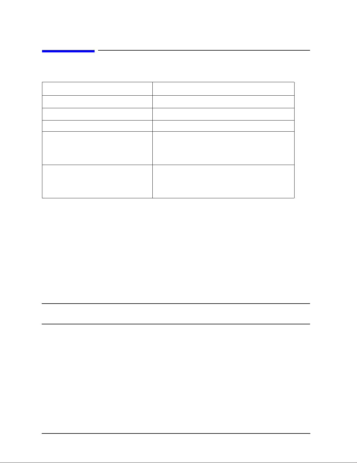
Table 2-1 Environmental Requirements
Parameter Limits
Operating temperature
Error-corrected temperature range
Storage temperature −40 °C to +75 °C (−40 °F to +167 °F)
Altitude
Operation < 4,500 meters (≈15,000 feet)
Storage < 15,000 meters (≈50,000 feet)
Relative humidity Always non-condensing
Operation 0 to 80% (26 °C maximum dry bulb)
Storage 0 to 90%
a. The temperature range over which the calib r ation standards maintain conformance to their
specifications.
b. The allowable network analyzer ambient temperature drift during measurement calibration
and during measurements when the network analyzer error correction is turned on. Also, the
range over which the network analyzer mai nt ai n s its specified performanc e w hil e c orr ec t io n
is turned on.
a
b
+20 °C to +26 °C (+68 °F to +79 °F)
±1 °C of measurement calibration temperature
Temperature—What to Watch Out For
Changes in temperature can affect electrical characteristics. Therefore, the operating
temperature is a critical factor in performance. During a measurement calibration, the
temperature of the calibration devices must be stable and within the range shown in
Table 2-1.
IMPORTANT Avoid unnecessary handling of the devices during calibration because your
fingers are a heat source.
2-2 85056K

Specifications
Mechanical Characteristics
Mechanical Characteristics
Mechanical characteristics such as center conductor protrusion and pin depth are not
performance specifications. They are, however, important supplemental characteristics
related to electrical performance. Agilent Technologies ve rifies the mechanical
characteristics of t he devices in the kit with s pecial gaging proces ses and elec trical tes ting.
This ensures that the device connectors do not exhibit any center conductor protrusion or
improper pin depth when the kit leaves the factory.
"Gaging Connectors," on page 3-16 explains how to use gages to determine if the kit
devices have maintained their mechanical integrity. Refer to Table 2-2 on page 2-4 for
typical an d ob served pin de p th limits.
Pin Depth
Pin depth is the distance the center conductor mat ing plane differs from being flush with
the outer co n d uctor mating plane. See Figure 2-1. The pin depth of a connector can be in
one of two states: either protruding or recessed.
Protrusion is the condition in which the center conductor extends beyond the outer
conductor mating plane . Thi s condit ion will indi cate a posi tive value o n the con nect or gage.
Recession is the condition in which the center conductor is set back from the outer
conductor mating plane. This con dition will indicate a negative value on the connector
gage.
Figure 2-1 Connector Pin Depth
85056K 2-3

Specifications
Mechanical Characteristics
The pin depth value of each calibration device in the kit is not specified, but is an
important mechanical parameter. The electrical performance of the device depend s, to
some extent, on its pin depth. The electrical sp ecifications for each device in the kit take
into account the effect of pin depth on the device’s performance. Table 2-2 lists the typical
pin depths and measurement unce rtai nties, and provides observed pin dep th limits for the
devices in the kit. If the pin depth of a device does not measure within the observed pin
depth limits, it may be an indication that the device fails to meet electrical specifications.
Refer to Figure 2-1 for a visual representati on of proper pin depth (slightly recessed).
Table 2-2 Pin Depth Limits
Device
Opens 0 to −0.0127 mm
Shorts 0 to −0.0127 mm
Fixed lo ads −0.0025 to −0.0203 mm
Sliding loads
Adapters
(2.4 to 2.4)
Adapters
(2.4 to 2.92)
a. Approximately +2 sigma to −2 sigma of gage uncertainty based on studies done at the factory
b. Observed pin depth limits are the range of observation limits seen on the gage reading due to
c. The 2.4 mm to 2.92 mm adapters require a 3.5 mm connector gage to measure the 2.92 mm end.
c
according to recommended procedures.
measurement uncertainty. The depth could still be within specifications.
Refer to
Typical Pin Depth
0 to −0.00050 in
0 to −0.00050 in
−0.00010 to −0.00080 in
0 to −0.0127 mm
0 to −0.00050 in
0 to −0.0381 mm
0 to −0.00150 in
0 to −0.0381 mm
0 to −0.00150 in
Table 6-2 on page 6-4 for Agilent part numbers and ordering information.
Measurement Uncertainty
+0.0030 to −0.0030 mm
+0.00012 to −0.00012 in
+0.0015 to −0.0015 mm
+0.00006 to −0.00006 in
+0.0030 to −0.0030 mm
+0.00012 to −0.00012 in
+0.0015 to −0.0015 mm
+0.00006 to −0.00006 in
+0.0030 to −0.0030 mm
+0.00012 to −0.00012 in
+0.0030 to −0.0030 mm
+0.00012 to −0.00012 in
a
Observed Pin Depth Limits
+0.0030 to −0.0157 mm
+0.00012 to −0.00062 in
+0.0015 to −0.0142 mm
+0.00006 to −0.00056 in
+0.0005 to −0.0234 mm
+0.00002 to −0.00092 in
+0.0015 to −0.0142 mm
+0.00006 to −0.00056 in
+0.0030 to −0.0411 mm
+0.00012 to −0.00162 in
+0.0030 to −0.0411 mm
+0.00012 to −0.00162 in
b
2-4 85056K

Specifications
Electrical Specifications
Electrical Specifications
The electrical specifications in Table 2-3 apply to the devices in your calibration kit when
connected with an Agilent precision interface.
Table 2-3 Electrical Specifications for 85056K Calibration Kit
Device Specification Frequency (GHz)
Broadband loads Return loss ≥ 42 dΒ (ρ ≤ 0.00794) dc to ≤ 4
(male and female) Return loss ≥ 34 dΒ (ρ ≤ 0.01995) > 4 to ≤ 20
Return loss ≥ 30 dB (ρ ≤ 0.03162) > 20 to ≤ 26.5
Return loss ≥ 26 dB (ρ ≤ 0.05019) > 26.5 to ≤ 50
Sliding loads
a,b
Return loss ≥ 42 dΒ (ρ ≤ 0.00794) 4 to ≤ 20
(male and female) Return loss ≥ 40 dΒ (ρ ≤ 0.01000 ) > 20 to ≤ 36
Return loss ≥ 38 dB (ρ ≤ 0.01259) > 36 to ≤ 40
Return loss ≥ 36 dB (ρ ≤ 0.01585) > 40 to ≤ 50
Adapters Return loss ≥ 32 dΒ (ρ ≤ 0.02512) dc to ≤ 4
(2.4 mm to 2.4 mm) Return loss ≥ 30dΒ (ρ ≤ 0.03162) > 4 to ≤ 26.5
Return loss ≥ 25dB (ρ ≤ 0.05623) > 26.5 to ≤ 40
Return loss ≥ 20 dB (ρ ≤ 0.10000) > 40 to ≤ 50
Adapters
c
Return loss ≥ 24 dB (ρ ≤ 0.06310)
dc to ≤ 40
(2.4 mm to 2.92 mm)
Offset opens
d
± 0.5 ° deviation from nom inal
dc to ≤ 2
(male and female) ± 1.25 ° deviation from nominal > 2 to ≤ 20
± 1.75 ° deviation from nominal > 20 to ≤ 40
± 2.25 ° deviation from nominal > 40 to ≤ 50
Offset shorts
d
± 0.5 ° deviation from nom inal
dc to ≤ 2
(male and female) ± 1.25 ° deviation from nominal > 2 to ≤ 20
± 1.5 ° deviation from nominal > 20 to ≤ 40
± 2.0 ° deviation from nominal > 40 to ≤ 50
a. For Option 001 only
b. The specifications for the sliding load termination include the quality of the airline portions
within the sliding load combined with the effective stability element.
c. The 2.4 mm to 2.92 mm adapters are tested two at at time (connected together) at the factory.
d. The s pec ific ation s for the op en s and shorts are given as allowe d deviation from the no min al
model as defined in the standard definitions (see “Nominal Standard Definitions” on page A-13).
85056K 2-5

Specifications
Electrical Specifications
Supplemental Electrical Characteristics
2.4 mm to 2.92 mm adapter Charact eristics lis ts the ty pical elect rical char acteristic s of the
2.4 mm to 2.92 mm adapters in this kit. Values in this table are not specifications, but are
intended to provide useful application information by giving typical, but non-warranted,
performance parameters.
Table 2-4 2.4 mm to 2.92 mm adapter Characteristics
Frequency (GHz) Parameter Typical Value
DC to
> 2 to ≤ 20 Return Loss ≥ 35 dB (≤ 0.01778 ρ)
> 20 to ≤ 40 Return Loss ≥ 30 dB (≤ 0.03162 ρ)
DC to
DC to
≤ 2 Return Loss ≥ 38 dB (≤ 0.01259 ρ)
≤ 40 Electrical Length 39.631 ps ±0.14 ps
≤ 40 Insertion Loss < 0.075 dB (> 0.99140 ρ)
Residual Errors after Calibration
The 8510 “Specifications and Performance Verification” software can be used to obtain a
printout of the residual errors after a calibration has been performed. Refer to the
“Specifications and Performance Verification” section of the 8510 On-Site Service Manual
for information on how to use the software.
Certification
Agilent Technologies certifies that this p roduct met its publis hed s pecificat ions at the ti me
of shipment from the factory. Agilent further certifies that its cali bration measurements
are traceable to the United States National Institute of Standards and Technology (NIST)
to the extent allowed by the institute’s calibration facility, and to the calibration facilities
of other International Standards Organization members. See "How Agilent Verifies the
Devices in Your Kit," on page 4-2 for more information.
2-6 85056K

3 Use, Maintenance, and Care of the
Devices
85056K 3-1

Use, Maintenance, and Care of the Devices
Electrostatic Discharge
Electrostatic Discharge
Protection against electrostatic discharge (ESD) is essential while connecting, inspecting,
or cleaning connectors attached to a static-sensitive circuit (such as those found in test
sets).
Static electricity can build up on your body and can easily damage sensitive internal
circuit elements when discharged. Static discharges too small to be felt can cause
permanent damage. Devices such as calibration components and devices under test (DUT),
can also carry an electrostati c charge. To prevent damage to the test set, components , and
devices:
• always wear a grounded wrist strap having a 1 MΩ resistor in series with it when
handling components and devices or when making connections to the test set.
• always use a grounded, conductive table mat while making connections.
• always wear a heel strap when working in an area with a conductive floor. If you are
uncertain about the conductivity of your floor, wear a heel strap.
• always ground yourself before you clean, inspect, or make a connection to a
static-sensitive device or te st po rt. You can, for example , grasp the grounded oute r sh ell
of the test port or cable connector briefly.
• always ground the center conductor of a test cable before making a connection to the
analyzer test port or other static-sensitive device. This can be done as follows:
1. Connect a short (from your calibration kit) to one end of the cable to short the cent er
conducto r to th e ou ter conduct o r.
2. While wearing a grounded wrist strap, grasp the outer shell of the cable connector.
3. Connect the other end of the cable to the test port.
4. Remove the short from the cable.
Figure 3 -1 shows a typical ESD protection setup using a grounded mat and wrist strap.
Refer to Table 6-2 on page 6-4 for information on ordering sup plies for ESD protection.
Figure 3-1 ESD Protection Setup
3-2 85056K

Use, Maintenance, and Care of the Devices
Visual Inspection
Visual Inspection
Visual inspection and, if necessary, cleaning should be done every time a connection is
made. Metal particles from the connector threads may fall into the connector when it is
disconnected. One connection made with a dirty or damaged connector can damage both
connectors beyond repair.
In some cases, magnification is necessary to see damage to a connector; a magnifying
device with a magnification of ≥ 10x is recommended. However, not all defects that are
visible only under magnification will affect the electr ical performance of the conne ctor. Use
the following guidelines when evaluating the integrity of a connector.
Look for Obvious Defects and Damage First
Examine the connectors first for obvious defects and damage: badly worn plating on the
connector interface , deformed threads, or bent, broken, or misaligned center conductors.
Connector nuts should move smoothly and be free of burrs, loose metal particles, and
rough spots.
What Causes Connector Wear?
Connector wear is caused by connecting and disconnecting the devices. The more use a
connector gets, the fas ter it wears and degrades. The wear is greatly accelerated when
connectors are not kept clean, or are not connected properly.
Connector wear eventually degrades performance of the device. Calibration devices should
have a long life if their use is on the order of a few times per week. Replace de vices with
worn conne c to rs.
The test port connect ors on t he network analyzer test s et may ha ve many connections each
day, and are, therefore, more s ubject to wear. It is recommended that an adapter be used as
a test port saver to minimize the wear on the test set’s test port connectors.
Inspect the Mating Plane Surfaces
Flat contact between the connectors at all points on their mating pl ane surfaces is required
for a good connection. See Figure 2-1 on page 2-3. Look especially for de e p sc ra tches or
dents, and for dirt and metal particles on the connector mating plane surfaces. Also look
for signs of damage due to excessive or uneven wear or misalignment.
Light burnishing of the mating plane surfaces is normal, and is evident as light scratches
or shallow circular marks distributed more or less uniformly over the mating plane
surface. Other small defects and cosmetic imperfections are also normal. None of these
affect electrical or mechanical perf ormance.
If a connector shows deep scratches or dents, particles clinging to the mating plane
surfaces, or uneven wear, clean and inspect it again. Devices with damaged connectors
should be discarded. Determine the cause of damage before connecting a new, undamaged
connector in the same configuration.
85056K 3-3

Use, Maintenance, and Care of the Devices
Visual Inspection
Slotted Connectors (2.92 mm)
When using slotted connectors, inspect the contact fingers in the female center conductor
carefully. These can be bent or broken, and damage to them is not always easy to see. A
connector with damaged contact fingers will not make good electric al contact and must be
replaced.
NOTE This is particularly important when mating nonprecision to precision devices.
Precision Slotless Connectors (2.4 mm)
The female 2.4 mm connectors in this set are metrology-grade, precision slotless
connectors (PSC). Precision slot less connectors are used to improve accuracy. A
characteristic of metrology-grade connectors is directly traceability to national
measurement standards through their well-de fine d mechanic al d imensions. With PSCs on
test ports and standards, the accuracy achieved when measuring at 50 dB return loss
levels is comparable to using conventional slotted connectors measuring devices having
only 30 dB return loss. This repre sent s an accuracy improvement of about 10 times.
The female 2.92 mm connectors have slotted contacts and, therefore, cannot be considered
metrology-grade. Due to the extremely thin wall of the 2.92 mm female connector, a
slotless metrology-grade 2.92 mm connector pair does not currently exist.
Conventional female center conducto rs are slott ed and, whe n mated, are fl ared by the male
pin. Because physical dimensions determine connector impedance, this c hange in physical
dimension affects electrical performance, making it very difficult to perform precision
measurements with conventional slotted connectors.
The precision slotless connector was developed to eliminate this problem. The PSC has a
center conductor with a solid cylindrical she ll, the outside diameter of which does not
change when mated. Instead, the center conductor has an internal contact that flexes to
accept the male pin.
3-4 85056K

Use, Maintenance, and Care of the Devices
Calibration Information
Calibration Information
The 85056K Calibration Kit is designed to provide a calibrated 2.92 mm test po rt to
measure devices with 2.92 mm co nnectors , using 2.4 mm calibration standards a nd a s et of
precision 2.4 mm to 2.92 mm adapters. The nomi nal loss and delay of the 2.4 mm to 2.92
mm adapters are “de-embedded” from the resp onses of the 2.4 mm opens and shorts. This
de-embedding causes the physical cal ibration plane, at the 2.4 mm test port, to be
transformed to the 2.92 mm measurement plane with the insertion of the 2.4 mm to 2.92
mm adapter. Thus, the calibration appears to be performed at the 2.92 mm connector
interface. See the following illus tration.
Figure 3-2 The Calibration Plane versus the Measurement Plane
Since the reflection of the 2.4 mm to 2.92 mm adapter is assumed to be zero, its actual
reflection adds to the dir ectivity error of t he 2.4 mm calibration. The residual source matc h
and reflection tracking errors are also degraded by t he insert ion of the ad apt er. Because of
this degradation, this kit is not recommended for precision applications.
The contents of the 85056K calibration kit will support the following types of calibration:
• response calibration
• 1-port open, short, load (sliding load optional) calibration
• 2-port open, short, load, thru calibration
• 2-port open, short, load, unknown thru (PNA only)
Adapter removal calibration is not recommended using the 85056K calibration kit. The
adapter swapping technique is recommended for measuring non-insertable devices since
the adapters were designed to have matching characteristics. For the PNA, the unknown
thru calibration may be used. To do so, follow the “PNA Smart Cal Calibration Procedure
for the 85065K and 85056K01 Cal Kits” on page 3-9. Since 1-port calibration is also
required for full 2-port calibration, a detailed description of the full 2-port calibration is
85056K 3-5

Use, Maintenance, and Care of the Devices
Calibration Information
provided in the following section.
Full 2-Port Calibration Overview
The method used to achieve calibrated 2.92 mm connector measurements involves
calibrating both 2.4 mm test ports using 2.4 mm calibration standar ds: opens, shorts, and
loads. For Option 001 Kits, both the low band load and sliding load ar e used. The t est ports
need not be insertable. Then, two 2.4 mm to 2.92 mm adapters are connected back-to-back
between the test ports to provide the “thru” measurements. For example, if the test port
connectors are both female 2.4 mm connectors, a 2.4 mm male to 2.92 male adapter mated
with a 2.92 mm female to 2.4 mm male adapter can be used as the “thru”. This method
provides a better transmission calibration than using the 2.4 mm ports as the thr u.
The key to this calibration method lies in the fact that the calibration definitions disk
contains modified standard definitions. The nominal 2.4 mm open and short circuit
standard definitions are modified to account for the presence of the 2.4 mm to 2.92 mm
adapters after calibration. The measurements of the 2.4 mm standard are effectively
translated to the ends of the adapters so that the directivity, source match, and reflection
tracking error terms are transfo rmed to the ends of the adapters. The thru measurements
made with the 2.4 mm to 2.92 mm adapter pair accounts for the length and loss of the
adapters that are inserted after the 2.4 mm calibration. The load match and transmission
tracking error terms are directly characterized at the 2.92 mm mating plane.
This calibration method assumes that the adap ters bein g used have equal length and los s,
and that they are reflectionless. The metrology-grade adapters (2.4 mm to 2.4 mm only)
and the 2.4 mm to 2.92 mm adapter are designed and manufactured with very tight
tolerances and therefore exhibit very similar trans mission characteristics. They may be
interchanged, to measure non-insertables, without much degradation in performance.
The actual return loss of the adapters has the most i mpa ct on the effective directivity,
source match, and load match of the system. The 2.4 mm calibration residual errors are
degraded proportionally by the return los s of the adap ters . It is app roximately equal to the
RSS (adapter reflection coefficient, 2.4 mm calibration residual errors). The reflection
tracking degradation is a function of the difference between the assumed loss and delay
characteristics of the 2.4 mm/2.92 mm adapters and the actual transmission
characteristics of the adapters.
For best 2.92 mm measurement accuracy, a precision 2.92 mm calibration kit, such as the
Agilent N4692A Electronic Calibration Module or the Maury Microw ave 8770S mechanical
calibration kit, is recommended.
2-Port Calibration Procedures for 8510 Network Analyzers
NOTE The following two procedures are ap plicable using the s pecified calibration kit
definition files. If the VNA has an earlier version of the calibration kit
definition file, obtain a copy of the latest file from Agilent Technologies, Inc.
3-6 85056K

Use, Maintenance, and Care of the Devices
Calibration Information
Figure 3-3 Full 2-Port Calibration - Agilent 8510 VNA using calibration kit
definition CK_292MMA2 and lower
85056K 3-7

Use, Maintenance, and Care of the Devices
Calibration Information
Figure 3-4 Full 2-Port Calibration - Agilent 8510 VNA using calibration kit
definition CK_292MMA3 and higher
3-8 85056K

Use, Maintenance, and Care of the Devices
Calibration Information
2-Port Calibration Procedures for PNA Network Analyzers
The Agilent PNA series of network analyzers provides two calibration procedures for
mechanical calibration kits: the “Smart” Cal and the “Unguided” Cal. The “Smart” Cal
guides you through the calibration process by providing step by step instructions. It also
has many powerful built-in calibration features that can simplify the steps required to
calibrate the PNA. Because the 85056K 2.4 mm/2.92 mm Calibration Kit operates
differently from a standar d calibration kit, the “Smart” Cal procedure is recommended.
NOTE During calibration routines, the PNA refers to calibration devices and
adapters in terms of their conne ctor interface . For example, a male open has a
male connector.
PNA Smart Cal Calibration Procedure for the 85065K and 85056K01 Cal Kits
Refer to the Smart Cal flowchart in Figure 3-5 on page 3-10.
1. From the CALIBRATION menu, click CALIBRATION WIZARD.
2. Select SMART CAL, click NEXT.
3. At the SELECT DUT CONNECTORS dialog, choose device connector type and sex.
NOTE If the 2.92 mm connector selection is not available, click CANCEL to exit
Calibration Wizard. Click ADVANCED MODIFY CAL KIT, click IMPORT,
then select th e ca l ki t fi l e s fr o m th e Cal K i t da t a disk. Return to the
Calibration Wizard.
4. At the SELECT CAL KITS dialog, select either 85056K Broadband Load Cal Kit or
85056K01 Sliding load Cal Kit for both ports . Select the MODIFY CAL check box.
5. At the SELECT CAL dialog, select UNKNOWN THRU if your DUT is non-insertable;
select INSERTABLE THRU if your DUT is insertable. Click NEXT.
6. Follow the device measurement sequence by connecting 1-port calibration standards to
the 2.4 mm test ports.
7. When instructed to connect the 2.4 mm to 2.92 mm adapter pair to ports 1 and 2,
connect the appropriate 2.92 mm adapters for the DUT measurements to the 2.4 mm
ports. If the DUT is insertable, connect port-1 to port-2 directly (insertable thru). If the
DUT is non-insertable, connect the unknown thru between the 2.92 mm adapters. The
DUT may be used as the unknown thru if it meets the reciprocity criteria,
S21=S12. See Figure 3-6 on page 3-11.
85056K 3-9

Use, Maintenance, and Care of the Devices
Calibration Information
Figure 3-5 Full 2-Port Calibration - Agilent PNA using the Smart Cal Procedure
3-10 85056K

Use, Maintenance, and Care of the Devices
Calibration Information
Figure 3-6 Unknown Thru Cal Setup and Insertable Thru Cal Setup
PNA Unguided Cal Cali brat ion Pr oced ure for the 85 06 5K and 8505 6K 01 Cal Kit s
Refer to the Unguided Cal flowchart in Figure 3-7 on page 3-12.
1. Ensure System ZO it is set to 50 ohms. Click SYSTEM then CONFIGURE, then
SYSTEM ZO.
2. From the CALIBRATION menu, click CALIBRATION WIZARD
3. Select UNGUIDED CAL
4. Select FULL SOLT 2-PORT and check VIEW OR SELECT CAL KIT.
5. Select 85056K Broadband Load Cal Kit or 85056K01 Sliding load Cal Kit
NOTE If the 2.92 mm cal kit is not a vailable , then clic k Cancel to exit the calib ration
wizard. Click ADVANCED MODIFY CAL KIT, click IMPORT, then select the
cal kit files from the Cal Kit data disk. Return to the Calibration Wizard
6. When measuring the THRU standard, connect the 2.4 mm/2.92 mm adapter pair (thru
standards) to the test ports.
7. If the 2.92 mm device being tested is a non-insertable, swap out one of the 2.4 mm to
2.92 mm adapters with one that will mate with the test devi ce. See Figure 3-8 on
page 3-13.
85056K 3-11

Use, Maintenance, and Care of the Devices
Calibration Information
Figure 3-7 Full 2-Port Calibration - Agilent PNA using the Unguided Cal
Procedure
3-12 85056K

Figure 3-8 Adapter Swapping
Use, Maintenance, and Care of the Devices
Calibration Information
85056K 3-13

Use, Maintenance, and Care of the Devices
Cleaning Connectors
Cleaning Connectors
Clean connectors are essential for ensuring the integrity of RF and microwave coaxial
connections.
1. Use Compressed Air or Nitrogen
WARNING Always use protective eyewear when using compressed air or
nitrogen.
Use compressed air (or nitrogen) to loosen particles on the connector mating plane
surfaces. Clean air cannot damage a connector or leave particles or residues behind.
You can use any source of clean, dry, low-pressure compressed air or nitrogen that has
an effective oil-vapor filter and liquid cond ensation trap placed just before the outlet
hose.
Ground the hose nozzle to prevent electrostatic discharge, and set the air pressure to
less than 414 kP a (60 psi) to control t he velocity of the air st ream. High-velocity st reams
of compressed air can cause electros tatic effects when directed into a connector. These
electrostatic effects can damage the device. Refer to “Electrostatic Discharge” earlier in
this chapter for additional infor mat ion.
2. Clean the Connector Threads
WARNING Keep isopropyl alcohol away from heat, sparks, and flame. Store in a
tightly closed container . It is extremely flammable. In case of fire, use
alcohol foam, dry chemical, or carbon dioxide; water may be
ineffective.
Use isopropyl alcohol with adequate ventilation and avoid contact
with eyes, skin, and clothing. It caus es skin ir ritati on, may cause eye
damage, and is harmful if swallowed or inhaled. It may be harmful if
absorbed through the skin. Wash thoroughly after handling.
In case of spill, soak up with sand or earth. Flush spill area with
water.
Dispose of isopropyl alcohol in accordance with all applicable
federal, state, and local environmental regulations.
Use a lint-free swab or cleaning cloth moistened with isopropyl alcohol to remove any
dirt or stubborn contaminants on a connector that cannot be removed with compressed
air or nitrogen. Refer to Table 6-2 on page 6- 4 for part numbers for isopropyl alc ohol and
cleaning swabs.
a. Apply a small amount of isopropyl alcohol to a lint-free cleaning swab.
b. Cl e an th e connector th reads.
3-14 85056K

Use, Maintenance, and Care of the Devices
Cleaning Connectors
c. Let the alcohol evaporate, then blow the threads dry with a gentle stream of clean,
low-pressure compressed air or nitrogen. Always completely dry a connector before
you reassemble or use it.
3. Clean the Mating Plane Surfaces
a. Apply a small amount of isopropyl alcohol to a lint-free cleaning swab.
b. Clean the center and outer conductor mating plane surfaces. Refer to Figure 2-1 on
page 2-3. When cleaning a female connector, avoid snagging the swab on the center
conductor contact fingers by using short strokes.
c. Let the alcohol evaporate , then bl ow the connec tor dr y with a ge ntle stream of c lean,
low-pressure compressed air or nitrogen. Always completely dry a connector before
you reassemble or use it.
4. Inspect
Inspect the connector t o make s ure t hat no par tic l es or r esi due remain. Refe r to “Visual
Inspection” on page 3-3.
85056K 3-15

Use, Maintenance, and Care of the Devices
Gaging Connectors
Gaging Connectors
The gages available from Agilent Technologies are intended for preventive maintenance
and troubleshooting purposes only. See Table 6-1 on page 6-2 and Tabl e 6-2 on p age 6-4 for
part number information. They are effective in detecting excessive center conductor
protrusion or recession, and conductor damage on DUTs, test accessories, and the
calibration kit devices. Do not use the gages for precise pin depth measurements.
Connector Gage Accuracy
The connector gages are only capable of performing coarse measurements. They do not
provide the degree of accuracy necessary to pr ecisely measure the pin depth of the kit
devices. This is partial ly due to the repeatability unc ertainties that are associated with the
measurement. Only the factory—through special gaging proce ss es and electrical testing—
can accurately verify the mechanical characteristics of the devices.
With proper technique, the gages are useful in detecting gross pin depth errors on device
connectors. To achieve maximum accuracy, random errors must be reduced by taking the
average of at least three measurements having different gage orientations on the
connector. Even the resultant average can be in error by as much as ± 0.0001 inch due to
systematic (biasing) errors usually resulting from worn gages and gage masters. The
information in Table 2-2 on page 2-4 assumes new gages and gage masters. Therefore,
these systematic errors were not included in the uncertainty analysis. As the gages
undergo more use, the sy stematic errors can become more signific ant in the accuracy o f the
measurement.
The measurement uncertainties are primarily a function of the assembly materials and
design, and the unique interaction each device type has with the gage. Therefore, these
uncertainties can vary among the different devic es. For example, note the difference
between the uncertainties of the opens and shorts in Table 2-2.
The observed pin depth limits in Table 2-2 add these uncertainties to the typical factory
pin depth values to provide practical limits that can be referenced when using the gages.
See “Pin Depth” on page 2-3. Refer to “Kit Co nt e nts” on page 1-2 for more information on
the design of the calibration devices in the kit.
NOTE When measuring pin depth, the measured value (resultant av erage of three
or more measurements) contains measurement uncertainty and is not
necessarily the true value. Always compare the measured value with the
observed pin depth limits (which account for measurement uncertainties) in
Table 2-2 on page 2-4 to evaluate the condition of device connectors.
3-16 85056K

Use, Maintenance, and Care of the Devices
Gaging Connectors
When to Gage Connectors
Gage a connector at the following times:
• Prior to using a device for the first time: record the pin depth measurement so that it
can be compared with future readings . (It will s erve as a good troubleshoo ting tool when
you suspect damage may have occurred to the device.)
• If either visual inspection or electrical performance suggests that the connector
interface m ay b e ou t of typical ran g e (d u e to w ear or damage, fo r example).
• If a calibration device is used by someone else or on another system or piece of
equipment.
• Initially after every 100 connections, and after that as often as experience indicates.
Gaging Procedures
Gaging 2.4 mm and 2.92 mm Connectors
CAUTION You must use 3.5 mm gages to measure the pin depth of 2.92 mm devices.
Never connect a 2.4 mm gage to a 2.92 mm device.
NOTE Always hold a connector gage by the gage barrel, below the dial indicator.
This gives the best stability, and improves measurement accuracy. (Cradling
the gage in your hand or holding it by the dial applies stress to the gage
plunger mechanism through the dial indicator housing.)
1. Select the proper gage for your connector. Refer to Table 6-1 on page 6-2 and Table 6-2
on page 6-4 for gage part numbers.
2. Inspect and clean the gage, gage master, and device to be gaged. Refer to “Visual
Inspection” on page 3-3 and “Cleaning Connectors” on page 3-14 earlier in this chapte r.
3. Zero the connector gage (refer to Figure 3-9 on page 3-19):
a. While holding the gage by the barrel, and without turning the gage or the devi ce,
connect the gage to the gage master by interconnecting the male and female
connectors. Connect the nut finger tight. Do not overtighten.
b. Using an open-end wrench to keep the device body from rotating, use the torque
wrench included in the kit to tighten the connecting nut to the specified torque. Refer
to “Final Connection Using a Torque Wrench” on page 3-25 for additional
information.
c. As you watch the gage pointer, gently tap the barrel of the gage to settle the reading.
The gage pointer should line up exactly with the zero mark on the gage. If not, adjust
the zero set knob until the gage pointer lines up exactly with the zero mark.
d. Remove the gage master.
85056K 3-17

Use, Maintenance, and Care of the Devices
Gaging Connectors
4. Gage the device connector (refer to Figure 3-9 on page 3-19):
a. While holding the gage by the barrel, and without turning the gage or the dev ice,
connect the gage to the device by interconnecting the male and female connectors.
Connect the nut finger-tight. Do not overtighten.
b. Using an open-end wrench to keep the device body from rotating, use the torque
wrench included in the kit to tighten the connecting nut to the specified torque. Refer
to “Final Connection Using a Torque Wrench” on page 3-25 for additional
information.
c. Gently tap the barrel of the gage with your finger to settle the gage reading .
d. Read the gage indicator dial. Read only the black ± signs; not the red ± signs.
For maximum accuracy, measure the connector a minimum of three times and take
an average of the readings. After each measurement, rotate the gage a quarter-turn
to reduce measurement variations that result from the gage or t he connector face no t
being exactly perpendicular to the center axis.
e. Compar e the average reading with the observed pin depth limits in T able 2-2 on page
2-4.
3-18 85056K

Figure 3-9 Gaging a 2.4 mm and 2.92 mm Connectors
Use, Maintenance, and Care of the Devices
Gaging Connectors
85056K 3-19

Use, Maintenance, and Care of the Devices
Gaging Connectors
Gaging the 2.4 mm Sliding Loads (Option 001 only)
Gage the sliding load before each use. If the slidi ng load pin dep th is out of the observed
pin depth limits listed in Table 2-2 on page 2-4, refer to “ Adjusting the Sliding Load Pin
Depth” on page 3-23.
NOTE Always hold a connector gage by the gage barrel, below the dia l indicator.
This gives the best stability, and improves measurement accuracy. (Cradling
the gage in your hand or holding it by the dial applies stress to the gage
plunger mechanism through the dial indicator housing.)
NOTE The sliding load uses a plastic centering bead to support its center conductor
when pin depth is adjusted and gaged and when the load is stored. Remove
this support bead from the sliding load before you connect the load for an
electrical calibration. Reinsert this sup port bead when you’ve finished using
the sliding load.
1. Select the proper gage for your connector. Refer to Table 6-1 on page 6-2 for gage part
numbers.
2. Inspect and clean the gage, gage master, and device to be gaged. Refer to “Visual
Inspection” on page 3-3 and “Cleaning Connectors” on page 3-14 earlier in this chapte r.
3. Zero the connector gage (refer to Figure 3-10 on page 3-21):
a. While holding the gage by the barrel, and without turning the gage or the dev ice,
connect the gage to the gage master by interconnecting the male and female
connectors. Connect the nut finger-tight. Do not overtighten.
b. Using an open-end wrench to keep the body of the s lidi ng load f rom rotat ing, use the
torque wrench included in the kit to tighten the connecting nut to 90 N-cm (8 in-lb).
Refer to “Final Connection Using a Torque Wrench” on page 3-25 for additional
information.
c. As you watch the gage pointer, gently tap the barrel of the gage to settle the reading.
The gage pointer should line up exactly with the zero mark on the gage. If not, adjust
the zero set knob until the gage pointer lines up exactly with the zero mark.
d. Remove the gage master.
4. Gage the sliding load connector (refer to Figure 3-10 on page 3-21):
a. Unlock the center conductor pullback mechanism by raising the pullback handle to
the unlocked position.
b. Carefully move the pullback mechanism toward the conne ctor end of the sliding load.
The center conductor will extend beyond the end of the co nnector. Continue to hold
the pullback mechanism in this position.
c. Pull the sliding ring back approximately 0.5 in and install a centering bead (if not
already installed) in the connector end of the sliding load.
3-20 85056K

Use, Maintenance, and Care of the Devices
Gaging Connectors
CAUTION The sliding load center conductor can be damaged if the sliding load is not in
alignment with the mating connector while making the connection.
d. Keep the center conductor extended by holding the center conductor pullba ck
mechanism toward the connector end of the sliding load. Align the sliding load with
the mating connector on th e ga g e an d mate the sliding load cen t er conducto r w i th
the gage center conductor.
e. Release the center conductor pullback mechanism and move the body of the sliding
load toward the gage to mate the outer conductor of the sliding load connector with
the outer con ductor of the ga ge connector.
f. Without turn i n g th e gage or the sli ding load, con n e ct the gage to the sliding loa d
being measured by interconnecting the male and female conne ctors . Conne ct the nut
finger-tight. Do not overtighten.
g. Using a 5/16-in wrench to keep the body of the sliding load from rotating, use the
torque wrench included in the kit to tighten the connecting nut to 90 N-cm (8 in-lb).
Refer to “Final Connection Using a Torque Wrench” on page 3-25 for additional
information.
CAUTION Always move the center conductor pullback mechanism back before locking
the handle. Do not force the handle past the locked position.
Figure 3-10 Gaging the 2.4 mm Sliding Loads
h. Move the center conductor pullback mechanism back (away from the connec tor end
of the sliding load), and place the pullback handle in its locked position.
i. Gently tap the barrel of the gage with your finger to settle the gage reading.
85056K 3-21

Use, Maintenance, and Care of the Devices
Gaging Connectors
j. Read the gage indicator dial. Read only the black ± signs; not the red ± signs.
For maximum accuracy, measure the connector a minimum of three times and take
an average of the readings. Use different orientations of the gage within the
connector. After each measurement, rotate the gage a quarter-turn to reduce
measurement variations that result from the gage or the connecto r face not being
exactly perpendicular to the center axis.
k. Compare the average reading with the observed pin depth limits in T able 2-2 on page
2-4. If the pin depth is outside the limits, it must be adjusted before proceeding.
Refer to “Adjusting the Sliding Load Pin Depth” on page 3-23.
l. Without turning the gage or the sliding load, loosen the connect ion between the gage
and the sliding load and remove the sliding load from the gage.
m.Leave the centering bead installed on the sliding load if you are going to adjust the
pin depth. If, instead, you are going to use the sliding load for an electrical
calibration, carefully remove the cente ring be ad. If t he ce ntering bead does not c ome
out of the sliding load easily:
i. Unlock the center conductor pullbac k hand le and move the center conductor
pullback mechanism toward the connector end of the sliding load to extend the
center conductor.
ii. While holding the center conductor pullbac k mechanism towar d the connector end
of the sliding load, remove the centering bead.
If the centering bead still will not come out:
i. Hold the sliding load with the connector end pointed downward.
ii. Move the sliding ring up, then quickly down. The trapped air behind the centering
bead should eject it.
Return the center conductor pullback mechanism to the rear of the sliding load and
return the pullback handle to its locked position.
CAUTION Damage can occur to the sliding load during the removal of a centering bead
that has slipped too far into the sliding load. If you’re going to perform an
electrical calibration, prevent damage by removing the centering bead
immediately after gaging the sliding load pin depth. The sliding load will not
perform to its specifications if the centering bead is not removed before an
electrical calibration is performed.
3-22 85056K

Use, Maintenance, and Care of the Devices
Gaging Connectors
Adjusting the Sliding Load Pin Depth
The sliding loads in this kit have a setback mechanism that allows the pin depth to be set
to any desired value. The pin depth of the sliding load is preset at the factory. The pin
depth should not have to be res et eac h time the sl iding load is used, but it should be checked
before each use.
If the pin depth is outside the observed limits listed in Table 2-2 on page 2-4, use the
following procedure to reset it to the nominal value of −0. 00381 mm (−0.00015 in).
This procedure assumes that you were directed here from “Gaging the 2.4 mm Sliding
Loads” on page 3-21. If not, perform the steps in that procedure before performing this
procedure.
1. The gage should be attached to the sliding load. The sliding load should have its
centering bead installed. Refer to “Gaging the 2.4 mm Sliding Loads” on page 3-21 if
necessary.
2. The face of the gage and the label on the sliding load should be facing up.
3. The center conductor pullback handle should be in the locked position.
4. With a small screwdriver, gently turn the center conductor pin depth adjustment screw
until the gage pointer reads −0.00381 mm (−0.00015 in). Refer to Figure 3-11.
5. Wait approximately five minutes to allow the temperature to stabilize. Do not touch
either the gage or the sliding load during this time.
6. Note the gage reading. If it is no longer within the allowable range, perform step 4
again.
7. Move the center conductor pullback handle to the unlocked positi on and then back to
the locked posi tion. The gage reading shou l d re t urn to the value previously s et . If not,
repeat steps 4 through 7.
8. Return to “Gaging the 2.4 mm Sliding Loads” on page 3-21.
85056K 3-23

Use, Maintenance, and Care of the Devices
Gaging Connectors
Figure 3-11 Adjusting the Sliding Load Pin Depth
3-24 85056K

Use, Maintenance, and Care of the Devices
Making Connections
Making Connections
Good connections require a skilled operat or. The most common cause of measu rem ent err or
is bad connections. The following procedures illustrate how to make good connections.
How to Make a Connection
Preliminary Connection
1. Ground yourself and all devices. Wear a grounded wrist strap and work on a grounded,
conductive table mat. Refer to “Electrostatic Discharge” on page 3-2 fo r ES D
precautions.
2. Visua l l y in s p e c t the connecto rs. R ef e r to “Visual Inspe c ti on” on page 3-3.
3. If necessary, clean the connectors. Refer to “Cleaning Connectors” on page 3-14.
4. Use a connector gage to verify that all center conductors are within the observed pin
depth values in Table 2-2 on page 2-4. Refer to “Gaging Connectors” on page 3-16.
5. Carefully align the connectors. The male connector center pin must slip co ncentrically
into the contact finger of the female connector.
CAUTION Only turn the connector nut. Do not turn the device body. Damage to the
center conductor can occur if the devi ce bo dy is twisted.
6. Push the connectors straight together and tighte n the conne ctor nut fing er ti ght. As the
center conductors mate, the re is usually a slight resistance.
7. The preliminary connection is tight enough when the mating plane surfaces make
uniform, light contact. Do not overtighten this connection.
A connection in which the outer conductors make gentle contact at all points on both
mating surfaces is sufficient. Very light finger pressure is enough to accomplish this.
8. Make sure the connectors are properly supported. Relieve any side press ure on the
connection from long or heavy devices or cables.
Final Connection Using a Torque Wrench
Use a torque wrench to make a final connection. Table 3-1 provides information about the
torque wre n ch r ec ommended fo r use w i th th e ca l ibration kit. A t or q u e wr e n ch is i n cluded
in the calibration kit. Refer to Table 6-1 on page 6-2 for replacement part number and
ordering information.
85056K 3-25

Use, Maintenance, and Care of the Devices
Making Connections
Table 3-1 Torque Wrench Information
Connector Type Torque Setting Torque Tolerance
2.92 mm 56 N-cm (5 in-lb) 5.6 N-cm (±0.5 in-lb)
2.4 mm 90 N-cm (8 in-lb) 9.0 N-cm (±0.8 in-lb)
Using a torque wrench guarantees that the c onnec tion is no t too tight , pr eventing pos sible
connector damage. It also guarantees that all connections are equally tight each time.
Prevent the rotation of anything other than the connect or nut that you are tightening. It
may be possible to do this by hand if one of the connectors is fixed (as on a test port).
However, it is recommended that you use an open-end wrench to keep the body of the
device from turning.
1. Position both wrenches within 90 degr ees of each other before applying force. See
Figure 3-12. Wrenches oppo sing eac h other ( great er th an 90 degrees apart ) will cause a
lifting action which can misalign and stress the connections of the devices involved.
This is especially true when several devices are connected together.
Figure 3-12 Wrench Positions
2. Hold the torque wrench lightly, at the end of the handle only (beyond the groove). See
Figure 3-13.
3-26 85056K

Use, Maintenance, and Care of the Devices
Making Connections
Figure 3-13 Using the Torque Wrench
3. Apply downward force perpendicular to the wrench handle. This applies torque to the
connection through the wrench.
Do not hold the wrench so tightly that you push the handle straight down along its
length rather than pivoting it, otherwise you apply an unknown amount of torque.
4. Tighten the connection just to the torque wrench break point. The wrenc h handle gives
way at its internal pivot point. See Figure 3-13. Do not tighten the connection further.
CAUTION You don’t have to fully break the handle of the torque wrench to reach the
specified torque; doing so can cause the handle to kick back and loos en the
connection. Any give at all in the handle is sufficient torque.
Connecting the Sliding Load
(Option 001 only)
NOTE The sliding load uses a plastic centering bead to support its center conductor
when pin depth is adjusted and gaged and when the load is stored. Remove
this support bead from the sliding load before you connect the load for an
electrical calibration. Reinsert this sup por t bead when you’ve finished using
the sliding load.
CAUTION Circuitry inside the test set at the test ports may be destroyed if precautions
are not taken to avoid electrostatic discharge (ESD). During this procedure,
the center conductor of the sliding load is connected to the exposed center
conductor o f th e te st port. Ground yo u r se l f to prevent electr ostatic discha rge.
CAUTION The sliding load center conductor can be damaged if the sliding load is not
held in line when mating the load to a connector. Always line up the sliding
load when connecting or removing it from a connector.
1. Unlock the center conductor pullback mechanism by raising the pullback handle to the
unlocked positi on. R efer to Figure 3-14 on page 3-28.
2. Carefully move the pullback mechanism toward the connector end of the sliding load.
85056K 3-27

Use, Maintenance, and Care of the Devices
Making Connections
The center conductor will extend beyond the end of the co nductor. Continue to hold the
pullback mechanism in this position.
CAUTION The sliding load center conductor can be damaged if the sliding load is not in
alignment with the mating connector while making the connection.
3. Keep the center conductor extended by holding the center conductor pullback
mechanism toward the co nnector en d of the slid ing load. Align t he sliding lo ad with t he
mating connector on the ca ble or test port to w h ich it is being con nected and ma te th e
sliding load center conductor with the center conductor of the cable or test port.
4. Release the center conductor pullback mechanis m and move the body of the s liding load
toward the cable or test port to mate the outer conductor of the sliding load connector to
the outer con ductor of the ca b l e o r te st port conne ct o r.
5. Without turning the sliding load, connect the sliding load to the cable or test port by
interconnecting the male and female connectors. Connect the nut finger-tight. Do not
overtighten.
6. Using an open-end wrench to keep the body of the sliding load from rotating, use the
torque wrench included in the kit to tighten the connecting nut to 90 N-cm (8 in-lb).
Refer to “Final Connection Using a Torque Wrench” on page 3-25 for additional
information.
CAUTION Always move the center conductor pullback mechanism back before locking
the handle. Do not force the handle past the locked position.
7. Move the center conductor pullback mechanism back (aw ay from the connector end of
the sliding load), and place the pullback handle in its locked position.
Figure 3-14 Connecting the Sliding Load
3-28 85056K

Use, Maintenance, and Care of the Devices
Making Connections
How to Separate a Connection
To avoid later al (bending) force on the con nector mating pla ne surfaces , alw ays s upport the
devices and connections.
CAUTION Do not turn the device body. Only turn the connector nut. Damage to the
center conductor can occur if the devi ce bo dy is twisted.
1. Use an open-end wrench to prevent the device body from turning.
2. Use another open-end wrench to loosen the connecting nut.
3. Complete the separation by hand, turning only the connecting nut.
4. Pull the connectors straight apart without twisting , rocking, or bending either of the
connectors.
85056K 3-29

Use, Maintenance, and Care of the Devices
Using the Sliding Load (Option 001 only)
Using the Sliding Load (Option 001 only)
When performing a sliding load calibration, it is recommended that the sliding ring be set
at the marked positions (rings) along the sliding load body. Using the set marks ensures
that a broad distribution of phase angles is selected, thereby optimizing the calibration.
The set marks function as detents so that the internal center of the sliding ring can mate
with them. Because of this, the set mark being used cannot be seen but is fel t as the sliding
ring is moved from mark to mark during a calibration. Moving the sliding ring with only
the index fingers of both hands will incr ease your ability to de tect the sliding r ing detent at
each position.
1. Move the sliding ring forward as far as possible toward the connector end of the load.
2. Move the sliding ring back until you feel it detent at the first set mark. You should see
the two uncovered set marks between the back surface of the slidi ng ring and the center
conductor pullback end of the sliding load.
NOTE After a calibration has begun, al w a ys mo ve the s liding rin g toward the center
conductor pullback end of the sliding load. If you slightly overshoot the
desired mark by less than 0.5 mm (0.02 inch), do not move the sliding ring,
but continue with the calibration as if the sliding ring is set to the proper
position. If the sliding ring is moved toward the connector end of the load
during the calibration sequence, the calibration may be unstable and poor
measurements may result. If the desired pos i tion is overshot by more than
0.5 mm (0.02 inch), restart the calibration sequence from step 1.
To perform a calibration, refer to your network analyzer’s user’s guide for instructions.
Figure 3-15 Sliding Load Set Marks
3-30 85056K

Use, Maintenance, and Care of the Devices
Handling and Storage
Handling and Storage
• Install the protective end caps and store the calibration devices in the foam-lined
storage case when not in use.
• Never store connectors loose in a box, or in a desk or bench drawer. This is the most
common cause of connector damage during storage.
• Keep connectors clean.
• Do not touch mating plane surface s. Natural skin oils and microscopic particles of dirt
are easily transferred to a connector inte rface and are very difficult to remove.
• Do not set connectors contact-end down on a hard sur face. The plating and the mating
plane surfaces can be damaged if the interface comes in contact with any hard surface.
85056K 3-31

Use, Maintenance, and Care of the Devices
Handling and Storage
3-32 85056K

4 Performance Verification
85056K 4-1

Performance Verification
Introduction
Introduction
The performance of your calibration kit ca n only be veri fied by ret urning th e kit to Agile nt
Technologies for recertification. The equipment required to verify the specifications of the
devices in the kit has been specially manufactured and is not commercially available.
How Agilent Verifies the Devices in Your Kit
Agilent verifies the specifications of these devices as follows:
1. The residual microwave error terms of the test system are verified with precision
airlines and shorts that are directly traced to the National Institute of Standards and
Tec hnology (NIST). The airline and short charact eristics are developed from mechanical
measurements. The mechanical measurements and material properties are carefully
modeled to give very accurate electrical representation. The mechanical me asurements
are then traced to NIST through various plug and ring gages and other mechanical
measurements.
2. Each calibration device is electrically tested on this system. For the initial (before sale)
testing of the calibration devices , Agil ent includes the test measurement unc ertainty as
a guardband to guarantee each device meets the published specif ication. For
recertifications (after sale), no guardband is used and the measured data is compared
directly with the specification to determine the pass or fail status. The measurement
uncertain t y fo r ea ch device is, however, recorded in the cali b r at i o n report that
accompanies recertified k its.
These two steps establish a traceable link to NIST for Agilent to the extent allowed by the
institute’s calibration facility. The specifications data provided for the devices in the kit is
traceable to NIST through Agilent Technologies.
4-2 85056K

Performance Verification
Recertification
Recertification
The following will be provided with a recertified kit:
• a new calibra t i on st i cke r a ff i x e d to th e ca se
• a certificate of calibration
• a calibration report for each device in the kit listing measured values, specifications,
and uncertainties
NOTE A list of NIST traceable numbers may be purchased upon request to be
included in the calibration report.
Agilent Te chnologies offers a Standard calibration for the recertification of the kit. For
more information, contact Agilent Technologies. See Table on page 5-4 for contact
information.
How Often to Recertify
The suggested initial interval f or recertifica tion is 12 months or sooner. The actual need for
recertification depends on the use of the kit. After reviewing the results of the initial
recertification, you may establi sh a differ ent rec ertificatio n interval that r eflects t he usage
and wear of the kit.
NOTE The recertification interval should begin on the date the kit is first used after
the recerti fi c at i on date.
Where to Send a Kit for Recertification
Contact Agilent T echnologies for information on where to send your kit for recertification.
Contact information is listed on page 5-4. Refer to "Returning a Kit or Device to Agilent,"
on page 5-3 for details on sending your kit.
85056K 4-3

Performance Verification
Recertification
4-4 85056K

5 Troubleshooting
85056K 5-1

Troubleshooting
Troubleshooting Process
Troubleshooting Process
This manual contains limited information about network analyzer system operation. For
complete information, refer to the instrument documentation.
If you suspect a bad calibration, or if your network analyzer does not pass performance
verification, follow the steps in Figur e 5-1.
Figure 5-1 Troubleshooting Flowchart
5-2 85056K

Troubleshooting
Returning a Kit or Device to Agilent
Returning a Kit or Device to Agilent
If your kit or device requires service , contact Agilent Technologies for information on
where to send it. See “Contacting Agile nt” on page 5-4 for contact information. Include a
service tag (located near the end of this manual) on which you provide the following
information:
• your company name and address
• a technical contact person within your company, and the person’s complete phone
number
• the model number and serial number of the kit
• the part number and serial number of each device
• the type of service require d
•a detailed description of the problem and how the device was bein g used when the
problem occurred (such as calibration or measurement)
85056K 5-3

Troubleshooting
Contacting Agilent
Contacting Agilent
Online assistance: www.agilent.com/find/assist
Americas
Brazil
(tel) (+55) 11 4197 3700
(fax) (+55) 11 4197 3800
Canada
(tel) 888 447 7378
(fax) 905 282 6495
Asia Pacific and Japan
Australia
(tel) 1 800 225 574
(alt) 1 800 893 449
(fax) 1 800 681 776
(fax) 1 800 225 539
Japan (Bench)
(tel) 0120 32 0119
(alt) (+81) 426 56 7799
(fax) 0120 01 2144
Taiwan
(tel) 0800 047 661
(tel) 0800 047 669
(fax) 0800 047 667
Austria
(tel) 0820 87 44 11*
(fax) 0820 87 44 22
France
(tel) 0825 010 700*
(alt) (+33) (0)1 6453 5623
(fax) 0825 010 701*
Italy
(tel) (+39) (0)2 9260 8484
(fax) (+39) (0)2 9544 1175
Spain
(tel) (+34) 91 631 3300
(alt) (+34) 91 631 3000
(fax) (+34) 91 631 3301
Switzerland (Italian)
(tel) 0800 80 5353 opt. 3*
(alt) (+39) (0)2 9260 8484
(fax) (+41) (0)22 567 5314
(tel) = primary telephone number; (alt) = alternate telephone nu mber; (fax) = FAX number; * = in country number
China
(tel) 800 810 0508
(alt) 800 810 0510
(fax) 800 810 0507
(fax) 800 810 0362
Japan (On-Site)
(tel) 0120 802 363
(alt) (+81) 426 56 7498
(fax) (+81) 426 60 895 3
Thailand
(tel) 1 800 2758 5822
(alt) (+66) 259 3442
(fax) 1 800 656 336
Belgium
(tel) (+32) (0)2 404 9340
(alt) (+32) (0)2 404 9000
(fax) (+32) (0)2 404 9395
Germany
(tel) 01805 24 6333*
(alt) 01805 24 6330*
(fax) 01805 24 6336*
Luxemburg
(tel) (+32) (0)2 404 9340
(alt) (+32) (0)2 404 9000
(fax) (+32) (0)2 404 9395
Sweden
(tel) 0200 88 22 55*
(alt) (+46) (0)8 5064 8686
(fax) 020 120 2266*
United King dom
(tel) (+44) (0)7004 666666
(alt) (+44) (0)7004 123123
(fax) (+44) (0)7004 444555
Mexico
(tel) 1 800 734 7703
(fax) 1 800 734 7704
Hong Kong
(tel) 800 933 229
(fax) 800 900 701
Singapore
(tel) 1 800 275 0880
(fax) (+65) 683 6 0240
(fax) (+65) 675 5 1235
(fax) (+65) 675 5 1214
Malaysia
(tel) 1800 880 399
(fax) 1800 801 054
Europe
Denmark
(tel) (+45) 7013 1515
(alt) (+45) 7013 7313
(fax) (+45) 701 3 1555
Ireland
(tel) (+353) (0)1 890 924 204
(alt) (+353) (0)1 890 924 206
(fax)(+353) (0)1 890 924 024
Netherlands
(tel) (+31) (0)20 547 2111
(alt) (+31) (0)20 547 2000
(fax) (+31) (0)20 547 2190
Switzerland (French)
(tel) 0800 80 5353 opt. 2*
(alt) (+33) (0)1 6453 5623
(fax) (+41) (0)22 567 5313
United States
(tel) 800 829 4444
(alt) (+1) 303 662 3998
(fax) 800 829 4433
India
(tel) 1600 11 2 92 9
(alt) 1600 112 626
(fax) 1600 112 727
(fax) 1600 113 040
South Korea
(tel) 080 770 7774
(tel) 080 778 0011
(tel) 080 778 0012
(alt) +65 270 1207
(fax) 080 778 0013
(fax) +82 080 778-001 4
(fax) 080 770 7778
Finland
(tel) (+358) 10 855 2100
(fax) (+358) (0) 10 855 2923
Israel
(tel) (+972) 3 9288 500
(fax) (+972) 3 9288 501
Russia
(tel) (+7) 095 797 3963
(alt) (+7) 095 797 3900
(fax) (+7) 095 797 3901
Switzerland (German )
(tel) 0800 80 5353 opt. 1*
(alt) (+49) (0)7031 464 63 33
(fax) (+41) (0)1 272 7373
7/2/04
5-4 85056K

6 Replaceable Parts
85056K 6-1

Replaceable Parts
Introduction
Introduction
Table 6-1 lists the replacement part numbers for items included in the 85056K calibration
kit and Figure 6-1. illustrates eac h of these items.
Table 6-2 on page 6-4 lists the replacement part numbers for items not included in the
calibration kit that are either required or recommended for successful operation of the kit.
To order a listed part, note the description, the part number, and the quantity desired.
Telephone or send your order to Agilent Technologies. See “Contacting Agilent” on
page 5-4.
Table 6-1 Replaceable Parts for the 85056K Calibration Kit
Descriptiona
Calibration Devices (2.4 mm)
Male broadband load 1 00901-60003
Female broadband load 1 00901-60004
Male offset open 1 85056-60022
Female offset open 1 85056-60023
Male offset short 1 85056-60020
Female offset short 1 85056-60021
Adapters
2.4 mm
2.4 mm
2.4 mm
2.4 mm
2.4 mm
2.4 mm
−m− to −m−
−m− to −f−
−f− to −f−
−m− to 2.92 mm −m−
−m− to 2.92 mm −f−
−f− to 2.92 mm −m−
Qty
Per Kit
1 85056-60005
1 85056-60006
1 85056-60007
1 11904-60001
1 11904-60003
1 11904-60004
Agilent
Part Number
2.4 mm
Box (including foam pads) 1 85056-60019
Box (without foam pads) 1 5180-7862
Foam pad (for lid) 1 5181-5544
Foam pad (for lower case) 1 85052-80023
−f− to 2.92 mm −f−
Calibration Kit Storage Case
1 11904-60002
6-2 85056K

Table 6-1 Replaceable Parts for the 85056K Calibration Kit
Replaceable Parts
Introduction
Descriptiona
Wrenches
5/16 in, 90 N-cm (8 in-lb) torque wrench (for 2.4 mm connectors) 1 8710-1765
5/16 in, 90 N-cm (5 in-lb) torque wrench (for 2.92 mm connectors) 1 8710-1582
7 mm open-end wrench 1 8710-1761
Items Included Only With Option 001
2.4 mm Sliding Load
2.4 mm Sliding Load
2.4 mm male gage set (includes gage master) 1 11752-60108
2.4 mm female gage set (includes gage master) 1 11752-60107
Centering Bead (for gaging 2.4 mm sliding load) 2 85056-20001
Tube Packag e 1
Calibration definitions disk (8510 and PNA) 1 85056-10004
Specifications and performance verification disk
−m−
−f−
Miscellaneous Items
b
Qty
Per Kit
1 00915-60003
1 00915-60004
1 08510-10033
Agilent
Part Number
1540-0803
User’s and service guide
c
1 85056-90019
a. Refer to “Clarifying the Terminology of a Connector Interface” on page 1-5.
b. See the 8510 on-site service manual for instructions on using this disk.
c. See “Printing Copies of Documentation from the Web” on page iii.
85056K 6-3

Replaceable Parts
Introduction
Table 6-2 Items Not Included in the Calibration Kit
Descriptiona
Qty
Agilent
Part Number
3.5 mm Connector Gages (used for 2.92 mm connectors)
Male gage set (includes gage master) 1 11752-60106
Female gage set (includes gage master) 1 11752-60105
Open-End Wrench
5/16 in open-end wrench 1 8720-0015
ESD Protection Devices
Grounding wrist strap 1 9300-1367
5 ft grounding cord for wrist strap 1 9300-0980
2 ft by 4 ft conductive table mat with 15 ft grounding wire 1 9300-0797
ESD heel strap 1 9300-1308
Connector Cleaning Supplies
Isopropyl alcohol 30 ml 8500-5344
Foam-tipped cleaning swabs 100 9301-1243
a. Refer to “Clarifying the Terminology of a Connector Interface” on page 1-5.
6-4 85056K

Figure 6-1. Replaceable Parts for the 85056K Calibration Kit
Replaceable Parts
Introduction
85056K 6-5

Replaceable Parts
Introduction
6-6 85056K

A Standard Definitions
85056K A-1

Standard Definitions
Version Changes
Version Changes
Class assignments and standard definitions may change as more accurate model and
calibration methods are develop ed. The disk shipped with the kit will contain the most
recent ve rsion.
A-2 85056K

Standard Definitions
Standard Class Assignments
Standard Class Assignments
Class assignment organizes calibration standards into a format compatible with the error
models used in the measurement calibration. A cl ass or group of classes co rresp onds to the
systematic errors to be removed from the measured network analyzer res pons e. Table A-1
through A-7 list the classes used by the following network analyzers. This information
resides on the ca l i b ra t i on definition s di sk i n cl uded in the kit.
Table A-1 Standard Class Assignments for the 8510 with 2.4 mm Devices
Disk File Name: CK_24MMA4 Calibration Label: 2.4 mm A.4
Class A B C D E F G St andard
Class Label
S11A2 Open
S
B1 Short
11
S
C 9 10 12 Loads
11
S
A2 Open
22
S
B1 Short
22
S
C 9 10 12 Loads
22
Forward transmission 11 Thru
Reverse transmission 11 Thru
Forward match 11 Thr u
Reverse match 11 Thru
Forward isolation
Reverse isolation 9 Isolation
Frequency response 1 2 11 Response
TRL thru 14 Undefined
TRL reflect 1 Undefined
TRL line 15 Undefined
Adapter 13
a
9Isolation
Standard
Standard
5678
Adapter
TRL Option
: _____ System Z0 _ X__ Line Z
Cal Z
0
Set ref: ___X_ Thru __ _ _ Reflect
Lowband frequency:
0
85056K A-3

Standard Definitions
Standard Class Assignments
a. The forward isolation standard is also used for the isolation part of a response and
isolation calibration.
Table A-2 Standard Class Assignments for the 8510 with 2.92 mm Devices
Disk File Name: CK_292mmA2 Calibration Label: 2.92 mm A. 2
Class A B C D E F G St andard
Class Label
A2 Open
S
11
S
B1 Short
11
S
C 9 10 12 Loads
11
S
A2 Open
22
S
B1 Short
22
S
C 9 10 12 Loads
22
Forward transmission 11 Thru
Reverse transmission 11 Thru
Forward match 11 Thr u
Reverse match 11 Thru
Forward isolation
a
9Isolation
Standard
Reverse isolation 9 Isolation
Standard
Frequency response 1 2 11 Response
TRL thru Undefined
TRL reflect Undefined
TRL line Undefined
Adapter 13
5678
Adapter
TRL Option
: X System Z0 Line Z
Cal Z
0
0
Set ref: X Thru _ _ Reflect
Lowband frequency:
a. The forward isolation standard is also used for the isolation part of a response and
isolation calibration.
A-4 85056K

Standard Definitions
Standard Class Assignments
Table A-3 Standard Class Assignments for the 872x with 2.4 mm Devices
Calibration Label: [2.4mm]
Class A B C D E F G Standard
Class Label
S
A2 Open
11
S
B1 Short
11
S
C 356 Loads
11
A2 Open
S
22
S
B1 Short
22
S
C 356 Loads
22
Forward transmission 4 Thru
Reverse transmission 4 Thru
Forward match 4 Thru
Reverse match 4 Thru
Response 1 2 4 Response
Response & isolation 1 2 4 Response
TRL thru 4 Undefined
TRL reflect 2 Undefined
TRL line 3 5 6 Undefined
TRL Option
: System Z0 X Line Z
Cal Z
0
0
Set ref: X Thru Reflect
85056K A-5

Standard Definitions
Standard Class Assignments
Table A-4 Standard Class Assignments for the 872x with 2.92 mm Devices
Calibration Label: [2.92*]
Class A B C D E F G Standard
Class Label
S
A2 Open
11
S
B1 Short
11
S
C 356 Loads
11
A2 Open
S
22
S
B1 Short
22
S
C 356 Loads
22
Forward transmission 4 Thru
Reverse transmission 4 Thru
Forward match 4 Thru
Reverse match 4 Thru
Response 1 2 4 Response
Response & isolation 1 2 4 Response
TRL thru 4 Undefined
TRL reflect 2 Undefined
TRL line 3 5 6 Undefined
TRL Option
: System Z0 X Line Z
Cal Z
0
0
Set ref: X Thru Reflect
A-6 85056K

Standard Definitions
Standard Class Assignments
Table A-5 Standard Class Assignments for the PNA Series Network Analyzer
Calibra tion Kit Lab el:
2.4 mm/2.92 mm Model 85056K
Class
S
A2
11
S
B1
11
S
C3, 5, 6
11
S
T4
21
S
A2
22
S
B1
22
S
C3, 5, 6
22
S
T4
12
A
a
TRL ‘T’ 4
TRL ‘R’ 2
TRL ‘L’ 3, 5, 6
a. For additional ports, make sure values
match the correct sex of the port.
Table A-6 SOLT Class Assignments for the PNA 85056K 2.4 mm/2.92 mm
Broadban d Cal Kit
Class Label A B C D E F G
S
A
11
S11B
S11C
S22A
S22B
S22C
Forward transmission
Reverse transmission
Forward match
Reverse match
Isolation
413
918
112
413
918
112
19
19
19
19
112
85056K A-7

Standard Definitions
Standard Class Assignments
Table A-7 SOL T Class Assignments for the PNA 85056K01 2.4 mm/2.92 mm
Sliding Load Cal Kit
Class Label A B C D E F G
S
A
11
413
S11B
S11C
S22A
S22B
S22C
Forward transmission
Reverse transmission
Forward match
Reverse match
Isolation
918
321101112
413
918
321101112
19
19
19
19
112
A-8 85056K

Standard Definitions
Standard Class Assignments
Blank Forms
The standard class assignments may be change d to meet your specific requirements . Table
A-9 through page 12 are provided to record the modified standard class assignments.
Table A-8 Blank Form f or the PNA Series SOLT Class Assignments
Class Label A B C D E F G
S
A
11
S
B
11
S
C
11
S
A
22
S
B
22
S
C
22
Forward transmission
Reverse transmission
Forward match
Reverse match
Isolation
Table A-9 Blank Form for the 8510 Network Analyzer
Disk File Name: _______________________ Calibration Kit Label: ____________ ________
Class A B C D E F G Standard
Class Label
S
A
11
S
B
11
S
C
11
S
A
22
S
B
22
S
C
22
Forward transmission
Reverse transmission
Forward match
Reverse match
Forward isolation
a
Reverse isolation
85056K A-9

Standard Definitions
Standard Class Assignments
Table A-9 Blank Form for the 8510 Network Analyzer
Disk File Name: _______________________ Calibration Kit Label: ____________ ________
Class A B C D E F G Standard
Class Label
Frequency response
TRL thru
TRL reflect
TRL line
Adapter
TRL Option
: _____ System Z
Cal Z
0
0
__X__ Line Z
0
Set ref: __X__ Thru ______ Reflect
Lowband frequency: ___________
a. The forward isolation standard is also used for the isolation part of a response and
isolation calibration.
Table A-10 Blank Form for the 872x Series Network Analyzer
Disk File Name: ________________________
Tape File Number: _____________________
Class A B C D E F G Standard
S
A
11
B
S
11
S
C
11
S
A
22
S
B
22
S
C
22
Calibration Label: ____________________
Class Label
Forward transmission
Reverse transmission
Forward match
Reverse match
Frequency response
Response & isolation
A-10 85056K

Standard Class Assignments
Table A-10 Blank Form for the 872x Series Network Analyzer
Standard Definitions
Disk File Name: ________________________
Calibration Label: ____________________
Tape File Number: _____________________
Class A B C D E F G Standard
Class Label
TRL thru
TRL reflect
TRL line
TRL Option
: _____ System Z
Cal Z
0
0
Line Z
0
Set ref: Thru Reflect
85056K A-11

Standard Definitions
Standard Class Assignments
Table A-11 Blank Form for the PNA Series Network Analyzer
Calibration Kit Label:
_________________________
Class
S
A
11
S
B
11
S
C
11
S
T
21
S
A
22
S
B
22
S
C
22
S
T
12
A
a
TRL ‘T’
TRL ‘R’
TRL ‘L’
a. For additional ports, make s u re v a l ue s
match the correct sex of the port.
A-12 85056K

Standard Definitions
Nominal Standard Definitions
Nominal Standard Definitions
Standard definitions provi de the constants needed to mathematically model the electrical
characteristics (delay, attenuation, and impedance) of each calibration standard. The
nominal values of these constants are theoretically derived from the physical dimensions
and material of each calibrati on standard, or f rom actual measured res ponse. These value s
are used to determine the measurement uncertainties of the network analyzer. The
standard definitions in Tables A-12 through A-18 list typical calibration parameters used
by the following network analyzers to specify the mat hematical model of each device. This
information must be loaded into the network analyzer to perform valid calibrations. Refer
to your network analyzer’s user’s guide for instructions on loading calibration definitions.
NOTE The values in the standard definitions table are valid only over the specified
operating temperature range.
Setting the System Impedance
This contains only 50 ohm devices. Ensure the system impedance (Z0) is set to 50 ohms.
Refer to your network analyzer’s user’ s guide for instr uctions on setting s ystem impedance .
Version Changes
Class assignments and standard definitions may change as more accurate model and
calibration methods are developed.
85056K A-13

Standard Definitions
Nominal Standard Definitions
Table A-12 Standard Definitions for the 8510 with 2.4 mm Devices
System Z
a
= 50.0 Ω
0
Calibration Label: 2.4 mm A.4
Disk File Name: CK_24MMA4
2
Standard
Number
1
Short
2
Open
b
F
−15
C0 ×10
H
−12
Type
L0 ×10
d
2.1636 −146.35 4.0443 −0.0363 22.548 50 3.554 0 999 Coax Short
d 29.722 165.78 −3.5385 0.0710 20.837 50 3.23 0 999 Coax Open
F/Hz
−27
C1 ×10
H/Hz
−24
L1 ×10
F/Hz
−36
C2 ×10
2
H/Hz
−33
L2 ×10
3
4
5
6
7
8
e
Open
Open
Open
Open
6.9558 −1.0259 −0.01435 0.0028 0 50 0 0 999 Coax 3.5/2.92
e 5.9588 −11.195 0.5076 −0. 00243 0 50 0 0 999 Coax 3.5/SMA
e 13.4203 −1.9452 0.5459 0.01594 0 50 0 0 999 Coax 2.92/SMA
e 8.9843 −13.9923 0.3242 −0.00112 0 50 0 0 999 Coax 2.4/1.85
9 Load Fixed 0 50 0 0 999 Coax Broadband
Load
f
10
11 Delay/
thru
12 Load Fixed 0 50 0 0 4.001 Coax Lowband
13 Delay/
thru
14
15
16
17
18
19
20
21
3
F/Hz
−45
C3 ×10
3
Offset
Frequency
in GHz
H/Hz
−42
L3 ×10
or Sliding
c
in Ω
0
Delay in ps
Fixed
Z
Loss in GΩ/s
Min
Max
Sliding 0 50 0 3.999 999 Coax Sliding
0 5 0 0 0 999 Coax Thru
43.240 50 7.0 0 999 Coax Adapter
Coax or Waveguide
Standard Label
a. Ensure sy stem Z
of network analyzer is set to this value.
0
b. Open, short, load, delay/thru, or arbitrary impedance.
c. Load or arbitrary impedance only.
d. Typic al values on ly. Disk values may be different.
e. This standard type (open) is used to accurately mode l the adapte r listed in the Standard Label column.
f. For use with Option 001 only.
A-14 85056K

Nominal Standard Definitions
Table A-13 Standard Definitions for the 8510 with 2.92 mm Devices
Standard Definitions
System Z
a
= 50.0 Ω
0
Calibration Label: 2.92 mm A.3
Disk File Name: CK_292MMA3
2
Standard
Number
1
Short
2
Open
F
b
−15
C0 ×10
H
−12
Type
L0 ×10
d
2.1636 -146.35 4.0443 -0.0363 -17.128 50 4.16 0 999 Coax Short
d 29.722 165.78 -3.5385 0.071 -18. 842 50 4.47 0 999 Coax Open
−27
−24
F/Hz
C1 ×10
H/Hz
L1 ×10
F/Hz
−36
C2 ×10
2
H/Hz
−33
L2 ×10
3
4
e
5
Open
6
Open
7
Open
8
Open
6.9558 -1.0259 -0.01435 0.0028 0 50 0 0 999 Coax 3.5/2.92
e 5.9588 -11.195 0.5076 -0.00243 0 50 0 0 999 Coax 3.5/SMA
e 13.4203 -1.9452 0.5459 0.01594 0 50 0 0 999 Coax 2.92/SMA
e 8.9843 -13. 9923 0.3242 -0.00112 0 50 0 0 999 Coax 2.4/1.85
9 Load Fixed 0 50 0 0 999 Coax Broadband
Load
f
10
11 Delay/
thru
12 Load Fixed 0 50 0 0 4.001 Coax Lowband
13 Delay/
thru
3
F/Hz
−45
C3 ×10
3
Offset
Frequency
in GHz
H/Hz
−42
L3 ×10
c
or Sliding
Fixed
Delay in ps
in Ω
0
Loss in GΩ/s
Min
Z
Max
Coax or Waveguide
Standard Label
Sliding 0 50 0 3.999 999 Coax Sliding
50
0
0 999 Coax Thru
0
43.24 50 3.843 999 Coax Adapter
a. Ensure sy stem Z
of network analyzer is set to this value.
0
b. Open, short, load, delay/thru, or arbitrary impedance.
c. Load or arbitrary impedance only.
d. Typic al values on ly. Disk values may be different.
e. This standard type (open) is used to accurately mode l the adapte r listed in the Standard Label column.
f. For use with Option 001 only.
85056K A-15

Standard Definitions
Nominal Standard Definitions
Table A-14 Standard Definitions for the 872x Series with 2.4 mm Devices
System Z
Standard
1 Short 0 0 0 0 22.548 50 3.554 0 999 Coax Short
2 Open 29.72 165.78 −3.54 0.07 20.837 50 3.23 0 999 Coax Open
3 L oad Fixed 0 50 3.554 0 999 Coax Broadband
4Delay/
5
6 L oad Fixed 0 50 3.554 0 4.001 Coax Lowband
7
8
a
= 50.0 Ω
0
b
F/Hz
C2 ×10
3
F/Hz
−45
C3 ×10
Sliding 0 50 3.554 3.999 999 Coax Sliding
2
F
F/Hz
−15
−27
C1 ×10
Number
Type
thru
Load
C0 ×10
d
−36
Calibration Kit Label: [2.4 mm]
Offset Frequency
or Sliding
c
in Ω
Fixed
Delay in ps
0 50 3.554 0 999 Coax Thru
0
Z
in GHz
Coax or Waveguide
Loss in GΩ/s
Min
Max
Standard Label
a. Ensure system Z0 of network analyzer is set to this value.
b. Open, short, load, delay/thru, or arbitrary impedance.
c. Load or arbitrary impedance only.
d. For use with Option 001 only.
A-16 85056K

Standard Definitions
Nominal Standard Definitions
Table A-15 Standard Definitions for the 872x Series with 2.92 mm Devices
System Z
Standard
1Short −17.047 50 0 0 999 Coax Short
2 Open 33.17 −208.65 7.34 −0.020 −18.764 50 0 0 999 Coax Open
3 L oad Fixed 0 50 0 0 999 Coax Broadband
4Delay/
5
6 L oad Fixed 0 50 0 0 4.001 Coax Lowband
7
8
a
= 50.0 Ω
0
b
F/Hz
C2 ×10
3
F/Hz
−45
C3 ×10
Sliding 0 50 0 3.999 999 Coax Sliding
2
F
F/Hz
−15
−27
C1 ×10
Number
Type
thru
Load
C0 ×10
d
−36
Calibration Label: [2.92*]
Offset Frequency
or Sliding
c
Fixed
Delay in ps
−79.262 50 3.843 0 999 Coax Thru
in GHz
in Ω
0
Z
Loss in GΩ/s
Min
Max
Coax or Waveguide
Standard Label
a. Ensure system Z0 of network analyzer is set to this value.
b. Open, short, load, delay/thru, or arbitrary impedance.
c. Load or arbitrary impedance only.
d. For use with Option 001 only.
85056K A-17

Standard Definitions
Nominal Standard Definitions
Table A-16 Standard Definiti ons for the PNA Series with 2.92 mm Devices -
Broadband Load
System Z
a
= 50.0 Ω
0
Standard
Number
Label
Description
1 BROAD
BAND
LOAD
4OPEN - M-2.4 mm
9SHORT
12 BROAD
BAND
LOAD
13 OPEN - F-2.4 mm
18 SHORT
19 THRU 2.4 mm /
-M-
-M-
-F-
-F-
2.4 mm
male
broad
band
load
male
open
2.4 mm
male
short
2.4 mm
female
broad
band
load
female
open
2.4 mm
female
short
2.92 mm
adapter
pair
b
2.92 mm
MALE
2.92 mm
MALE
2.92 mm
MALE
2.92 mm
FEMALE
2.92 mm
FEMALE
2.92 mm
FEMALE
2.92 mm
FEMALE
/ MALE
Calibration Kit Label: Model
85056K 2.4 mm / 2.92 mm
Broadband Load Cal Kit
2
F
−18
C0 ×10
H
−12
L0 ×10
−30
−24
F/Hz
C1 ×10
H/Hz
L1 ×10
F/H
−39
C2 ×10
2
H/Hz
−33
L2 ×10
3
F/Hz
−48
C3 ×10
3
H/Hz
−45
L3 ×10
Offset
Delay in psZ0
Ω
Loss
in
GΩ/s
Ω
Ω/s
Connector/Sex
Fixed / Sliding
FIXED OFF OFF 0 50 0 0 999
29.722 165.780 3.53850 0.071 -18. 842 50 4.47 0 999
2.1636 -146.35 4.0443 -0.0363 -17.128 50 4.1 6 0 999
FIXED OFF OFF 0 50 0 0 999
29.722 165.780 3.53850 0.071 -18. 842 50 4.47 0 999
2.1636 -146.35 4.0443 -0.0363 -17.128 50 4.1 6 0 999
Arbitrary Imp
Offset Load
.0001 50 0 0 999
Frequency
in GHz
Min Max
a. Ensure system Z0 of network analyzer is set to this value.
b. Open, short, load, delay/thru, or arbitrary impedance.
A-18 85056K

Standard Definitions
Nominal Standard Definitions
Table A-17 Standard Definiti ons for the PNA Series with 2.92 mm Devices -
Sliding Load
System Z
0
Number
1 BROAD
BAND
LOAD
-M-
a
= 50.0 Ω
Standard
Label
b
Description
2.4 mm
male
broad
band
load
Connector/Sex
2.92 mm
MALE
Calibration Kit Label: Model
85056K01 2 .4 mm / 2.92 m m Sliding
Load Cal Kit
2
F
−18
C0 ×10
H
−12
L0 ×10
−30
−24
F/Hz
C1 ×10
H/Hz
L1 ×10
F/H
−39
C2 ×10
2
H/Hz
−33
L2 ×10
3
F/Hz
−48
C3 ×10
3
H/Hz
−45
L3 ×10
Offset
Delay in psZ0
Ω
Loss
in
GΩ/s
Ω
Frequency
in GHz
Min Max
Ω/s
Fixed / Sliding
FIXED OFF OFF 0 50 0 0 999
Arbitrary Imp
Offset Load
2SLIDING
LOAD
-M-
2.4 mm
male
sliding
load
3LOW
BAND
LOAD
-M-
2.4 mm
male
low
band
load
4OPEN - M-2.4 mm
male
open
9SHORT
-M-
2.4 mm
male
short
10 LOW
BAND
LOAD -F-
2.4 mm
female
low
band
load
11 SLIDING
LOAD -F-
2.4 mm
female
sliding
load
2.92 mm
MALE
2.92 mm
MALE
2.92 mm
MALE
2.92 mm
MALE
2.92 mm
FEMALE
2.92 mm
FEMALE
SLIDING OFF OFF 0 50 0 3.999 999
FIXED OFF OFF 0
004.001
50
29.722 165.780 3.5385 0.071 -18.842 50 4.47 0 999
2.1636 -146.35 4.0443 -0.0363 -17.128 50 4.16 0 999
FIXED OFF OFF 0 50 0 0 4.001
SLIDING OFF OFF 0 50 0 3.999 999
85056K A-19

Standard Definitions
Nominal Standard Definitions
Table A-17 Standard Definiti ons for the PNA Series with 2.92 mm Devices -
Sliding Load
System Z
a
= 50.0 Ω
0
Number
Label
12 BROAD
BAND
LOAD -F-
Standard
Description
2.4 mm
female
broad
band
load
b
2.92 mm
FEMALE
Calibration Kit Label: Model
85056K01 2 .4 mm / 2.92 m m Sliding
Load Cal Kit
2
F
−18
C0 ×10
H
−12
L0 ×10
−30
−24
F/Hz
C1 ×10
H/Hz
L1 ×10
F/H
−39
C2 ×10
2
H/Hz
−33
L2 ×10
3
F/Hz
−48
C3 ×10
3
H/Hz
−45
L3 ×10
Offset
Delay in psZ0
Ω
Loss
in
GΩ/s
Ω
Frequency
in GHz
Min Max
Ω/s
Connector/Sex
Fixed / Sliding
Arbitrary Imp
Offset Load
FIXED OFF OFF 0 50 0 0 999
13 OPEN - F-2.4 mm
female
2.92 mm
FEMALE
29.722 165.780 3.5385 0.071 -18.842 50 4.47 0 999
open
18 SHORT
-F-
2.4 mm
female
2.92 mm
FEMALE
2.1636 -146.35 4.0443 -0.0363 -17.128 50 4.16 0 999
short
19 THRU 2.4 mm
/ 2.92
mm
2.92 mm
FEMALE
/ MALE
adapte
r pair
a. Ensure system Z
of network analyzer is set to this value.
0
b. Open, short, load, delay/thru, or arbitrary impedance.
.0001 50 0 0 999
A-20 85056K

Standard Definitions
Nominal Standard Definitions
Table A-18 2.92 mm Connector Definitions for the PNA Series Analyzer - The
following connector definitions are included in the files that contain both the
broadband and sliding load definitions . For more information on connector
definitions, see the PNA online help file to pic “Modify Calibration Kits”
Connector
Description
2.92 mm 2.92 mm
MALE
2.92 mm 2.92 mm
FEMALE
Sex
Male COAX 0.0000 999000.
Male COAX 0.0000 999000.
Media
Min Freq (MHz)
Max Freq (MHz)
000
000
Cutoff Freq (MHz)
0.000
0.000
85056K A-21

Standard Definitions
Nominal Standard Definitions
Blank Forms
The standard definitions may be cha nge d to me et your sp ecific requirements. Table A-19
through A-21 are provided to record the modified standard definitions.
Table A-19 Blank Form for the 8510 Network Analyzer
System Z
a
= _____________
0
Disk File Name: ___________________________
Standard
Number
1
2
3
4
5
6
7
8
9
10
11
12
13
14
15
16
17
18
19
20
21
2
F
b
−15
C0 ×10
H
−12
Type
L0 ×10
−27
−24
F/Hz
C1 ×10
H/Hz
L1 ×10
F/Hz
−36
C2 ×10
2
H/Hz
−33
L2 ×10
3
F/Hz
−45
C3 ×10
3
H/Hz
−42
L3 ×10
Calibration Kit Label: ___________________________
c
or sliding
Fixed
Offset Frequency
Ω
Delay
0 in
Z
Loss in GΩ/s
Min
in GHz
Max
Coax or Waveguide
Standard Label
a. Ensure sy stem Z0 of network analyzer is set to this value.
b. Open, short, load, delay/thru, or arbitrary impedance.
c. Load or arbitrary impedance only.
A-22 85056K

Nominal Standard Definitions
Table A-20 Blank Form for the 872x Series Network Analyzer
Standard Definitions
System Z
Standard
Number
a
= __________
0
b
Type
F/Hz
C2 ×10
3
F/Hz
−45
C3 ×10
2
F
F/Hz
−15
C0 ×10
−27
C1 ×10
−36
Calibration Label: __________________
or Sliding
c
Fixed
1
2
3
4
5
6
7
8
a. Ensure system Z0 of network analyzer is set to this value.
b. Open, short, load, delay/thru, or arbitrary impedance.
c. Load or arbitrary impedance only.
Offset Frequency
in Ω
Delay in ps
0
Z
Loss in GΩ/s
in GHz
Min
Coax or Waveguide
Max
Standard Label
85056K A-23

Standard Definitions
Nominal Standard Definitions
Table A-21 Blank Form for the PNA Seri es Network Analyzer
System Z
Standard
Number
0
Type
a
= 50.0 Ω
b
2
F
−18
C0 ×10
H
−12
L0 ×10
−30
−24
F/Hz
C1 ×10
H/Hz
L1 ×10
F/H
−39
C2 ×10
2
H/Hz
−33
L2 ×10
3
F/Hz
−48
C3 ×10
3
H/Hz
−45
L3 ×10
Fixed or sliding
1
2
3
4
5
6
7
8
a. Ensure system Z0 of network analyzer is set to this value.
b. Open, short, load, delay/thru, or arbitrary impedance.
Calibra tion Kit Lab el:
Offset
Ω
0
Delay in ps
Loss in GΩ/s
Z
Frequency
in GHz
Min
Max
Coax or Waveguide
Standard Label
A-24 85056K

Index
A
adapters
Agilent Technologies
contacting
warranty, -ii
agreements
customer assistance, -ii
maintenance, -ii
alcohol
isopropyl
altitude
specifications, 2-2
antistatic mat
part number, 6-4
assistance
customer, -ii
who to contact, -ii
B
blank form
standard class assignments
standard definitions, A-22
box
pads
part number, 6-2
broadband loads, 1-2
part numbers, 6-2
specifications, 2-5
C
cal kit
documentation warranty
performance
calibration, 3-5
bad, 5-2
calibration plane, 3-5
certificate of, 4-3
definitions
full 2-port overview, 3-6
measurement plane, 3-5
MIL-STD 45662, 4-3
report, 4-3
temperature, 2-2
types of calibration, 3-5
calibration definitions disk
part number
calibration kit
contents
documentation warranty, -ii
overview, 1-2
performance
, 1-3
, 5-3
as cleaning solvent
part number, 6-4
precautions for use of, 3-14
part numbers
verifying
entering
permanently stored, 1-3
, 4-1
, 1-3
, 3-14
, 6-2
, 6-3
, 1-2, 6-5
drawing of, 6-5
, -ii
, A-9
how Agilent verifies
verifying, 4-1
case
part number, 6-2
certificate of calibration, 4-3
certification
of device specifications, 2-6
characteristics
mechanical
class assignments
blank form
standard, A-3
cleaning connectors, 3-14
cleaning supplies, 1-4
part numbers, 6-4
cleaning swabs, 3-14
part number, 6-4
compressed air
for cleaning
connections, 3-25
ESD protection, 3-25
final, 3-25
preliminary, 3-25
separating, 3-29
sliding load, 3-27
using torque wrench, 3-25
connector
cleaning, 3-14
damage, 3-3
defects, 3-3
female, 3-4
gage
accuracy
handling, 3-16, 3-17, 3-20
part numbers, 6-4
use of, 3-16
zeroing, 3-16, 3-17, 3-20
gaging, 3-16, 3-17
to determine pin depth, 3-16
when to do, 3-17
mating plane surfaces, 3-15
cleaning, 3-15
sex, 1-5
slotless, 3-4
threads
cleaning
visual inspecti on, 3-3
wear, 3-3
affect on electrical performance, 3-3
connector gages, 1-3
connector interface, 1-5
contacting Agilent Technologies, 5-3
contents
calibrat ion kit
drawing of, 6-5
incomplete
what to do
cord
grounding
part number
, 2-3
, A-9
, 3-14
, 3-16
, 3-14
, 6-5
, 1-4
, 6-4
, 4-2
85056K
Index-1

Index
D
damage
caused by electrostatic discharge
device, 3-3
what to do, 1-4
data
recertification
defective connectors, 3-3
definitions
standard, A-13
deviation from nominal phase, 2-5
device
connecting
damage, 3-3
disconnecting, 3-29
handling, 3-31
maintenance, 1-6
performance
verifying
specifications, 2-5
certification of, 2-6
traceability, 4-2, 4-3
storage, 3-31
temperature, 2-2
visual inspection, 3-3
disconnections, 3-29
disk
calibration definitions
part number
specifications and performance verification
part number
document warranty, -ii
E
electrical specification s
electrostatic discharge, See ESD
environmental
regulations
requirements, 2-2
specifications, 2-2
equipment required, 1-4
ESD, 3-2
antistatic mat
part number
heel strap
part number
precautions, 3-14
protection, 3-2
setup, 3-2
supplies, 3-2
part numbers, 6-4
wrist strap
part number
F
female connectors, 3-4
frequency
specifications
full size 2-port calibration, 3-6
, 4-3
, 3-25
, 4-1
, 6-3
, 6-3
, 2-5
, 3-14
, 6-4
, 6-4
, 6-4
, 2-5
, 3-2
G
gage
connector
handling, 3-17, 3-20
part numbers, 6-4
zeroing, 3-17, 3-20
gaging
connectors
when to do, 3-17
sliding loads, 3-20
to determine pin depth, 3-16
grounding cord
part number
H
handling
heel strap
part number
humidity
specifications
I
impedance
system
setting, A-13
incoming inspection, 1-4
inspection
damage, 3-3
female connectors, 3-4
incoming, 1-4
mating plane surfaces, 3-3
visual, 3-3
interace terminology, 1-5
isopropyl alcohol
as cleaning solvent, 3-14
part number, 6-4
precautions for use of, 3-14
K
kit
contents
drawing of, 6-5
overview, 1-2
L
limits
pin depth
loads
broadband
part numbers, 6-2
sliding, 1-3
M
maintenance
agreements, -ii
of devices, 1-6
preventive, 1-6
making connections, 3-25
, 1-4
, 3-16, 3-17
, 6-4
, 3-31
, 6-4
, 2-2
, A-13
, 1-2, 6-5
, 2-4
, 1-2
, 3-2
Index-2
85056K

Index
ESD protection
precautions, 3-25
mat
antistatic
part number
conductive table
part number
mating plane surfaces
cleaning, 3-15
connector, 3-15
inspection of, 3-3
mechanical characteristics, 2-3
affect on electrical performance, 2-3
verifying, 3-16
MIL-STD 45662
calibration, 4-3
N
National Institute of Standards and Technology
(NIST)
nitrogen
for cleaning
nominal standard definitions, A-13
numbers
replaceable parts, 6-2
serial, 1-5
recording, 1-5
O
observed limits
pin depth
offset opens
part numbers, 6-2
offset shorts
part numbers, 6-2
offsets, 1-2
open-end wrench, 1-4, 3-29
5/16 in
part number
7-mm
part number
opens, 1-2
part numbers, 6-2
specifications, 2-5
options, 1-3
ordering
P
pads
part numbers, 6-2
parts
, 6-2
parts
box
part numbers
of items in kit, 6-2
of items not in kit, 6-4
included in kit, 6-2
not included in kit, 6-2, 6-4
ordering, 6-2
, 3-25
, 6-4
, 6-4
, 2-6, 4-2
, 3-14
, 2-4
, 6-4
, 6-3
, 6-2
replaceable, 6-2
performance verification
, 5-2
fail
pin depth, 2-3
adjusting sliding load, 3-23
affect on electrical performance, 2-4
gaging to determine, 3-16
observed limits, 2-4, 3-16
protrusion, 2-3
recession, 2-3
typical values, 2-4
preventive maintenance, 1-6
protrusion
pin depth
R
recertification
how to order
interval, 4-3
what's included, 4-3
where it’s done, 4-3
recession
pin depth
regulations
environmental
replaceable parts, 6-2, 6-5
drawing of, 6-5
report, calibration, 4-3
requirements
environmental, 2-2
return
kit or device to Agilent, 5-3
return loss
specifications, 2-5
S
separating connections
serial numbers, 1-5
devices, 1-5
recording, 1-5
service, 5-3
service tag, 1-4, 4-3, 5-3
set marks
sliding load
setup
ESD protection
sex, connector, 1-5
shorts, 1-2
part numbers, 6-2
specifications, 2-5
sliding load
calibration
connecting, 3-27
pin depth
adjusting
set marks, 3-30
sliding ring, 3-30
using, 3-30
sliding loads, 1-3
gaging, 3-20
, 2-3
, 4-3
, 2-3
, 3-14
, 3-29
, 3-30
, 3-2
, 3-30
, 3-23
85056K
Index-3

Index
sliding ring
sliding load
specifications, 2-2
altitude
operating
storage, 2-2
certification of, 2-6
deviation from nominal phase, 2-5
device, 2-5
electrical, 2-5
environmental, 2-2
frequency, 2-5
humidity
operating
storage, 2-2
return loss, 2-5
temperature, 2-2
torque wrench, 3-25
traceability, 4-2, 4-3
specifications and performance verification disk
part number, 6-3
standard class assignments, A-3
blank form, A-9
standard definitions, A-13, A-22
blank form, A-22
nominal, A-13
standards
international
National Institute of Standards and Tec hnology
(NIST)
static
discharge, 3-2
electricity, 3-2
storage, 3-31
storage case
part number, 6-2
strap
heel
part number
wrist
part number
supplies
cleaning
part number, 6-4
swabs
cleaning
part number, 6-4
system impedance, A-13
T
tag
service
temperature
affect on electrical performance, 2-2
calibration, 2-2
cautions about, 2-2
changes in, 2-2
device, 2-2
error-corrected, 2-2
measurement, 2-2
, 3-30
, 2-2
, 2-2
, 2-6
, 2-6, 4-2
, 6-4
, 6-4
, 1-4
, 3-14
, 1-4, 4-3, 5-3
specifications, 2-2
operating, 2-2
storage, 2-2
verification and measurement, 2-2
test data, 4-3
threads
connector
cleaning
threads, connector
inspecting
tools
part numbers
torque wrench, 1-4
part number, 6-3
specifications, 3-25
traceability
of device specifications, 4-2, 4-3
troubleshooting, 5-2
U
user’s and service guide
part number
V
verification
temperature
visual inspection, 3-3
W
warranty, document
wear, connector, 3-3
affect on electrical performance, 3-3
wrench
7 mm open-end
part number
open-end, 1-4, 3-26, 3-29
part number, 6-4
proper positioning of, 3-26
torque, 1-4, 3-25, 3-26, 3-27
part number, 6-3
precautions for use of, 3-27
proper use of, 3-27
wrist strap
part number
Z
zeroing
connector gage
, 3-14
, 3-3
, 6-3
, 6-3
, 2-2
, -ii
, 6-3
, 6-4
, 3-17, 3-20
Index-4
85056K
 Loading...