

Page 1

Agilent Technologies 16557D
State/Timing Logic Analyzer
Programmer’s Guide
Insert this package in the back of either Programmer’s Guide binder included
with the Agilent Technologies 16500 Logic Analysis System
Programmer’s Guide.
Page 2

Page 3

Programmer’s Guide
Publication number 16557-97005
Second edition, January 2000
For Safety information, Warranties, and Regulatory
information, see the pages behind the Index
Copyright Agilent Technologies 1987-2000
All Rights Reserved
Agilent Technologies 16557D
State/Timing Logic Analyzer
Page 4

ii
Page 5
In This Book
This guide, combined with the
Technologies 16500/16501A
Programmer’s Guide
the information needed to program the
Agilent Technologies 16557D logic
analyzer module. Each module has its
own reference to supplement the
mainframe manual since not all
mainframes will be configured with the
same modules.
This manual is organized in three parts.
Part 1 consists of chapters 1 and 2 which
contain general information and
instructions to help you get started.
Chapter 1 also contains:
Mainframe system commands that are
•
frequently used with the logic analyzer
module
16557D logic analyzer command tree
•
Alphabetic command-to-subsystem
•
directory
Chapter 2 contains module-level
commands.
Part 2 consists of chapters 3 through 16
which contain the subsystem commands
for the logic analyzer and chapter 17
which contains information on the
SYSTem:DATA and SYSTem:SETup
commands for this module.
, provides you with
Agilent
1
2
3
4
5
6
7
8
9
10
11
12
13
Programming the 16557D
Module Level Commands
MACHine Subsystem
WLISt Subsystem
SFORmat Subsystem
STRigger (STRace) Subsystem
SLISt Subsystem
SWAVeform Subsystem
SCHart Subsystem
COMPare Subsystem
TFORmat Subsystem
TTRigger (TTRace) Subsystem
TWAVeform Subsystem
14
TLISt Subsystem
iii
Page 6

Part 3, chapter 18, contains program examples of actual tasks that show you
how to get started in programming the 16557D logic analyzer. These
examples are written in HP BASIC 6.2; however, the program concepts can
be used in any other popular programming language.
Error messages for the 16557D are included in generic system error
messages and are in the
Programmer’s Guide
Agilent Technologies 16500/16501A
.
iv
Page 7

15
SYMBol Subsystem
16
17
18
SPA Subsystem
DATA and SETup Commands
Programming Examples
Index
v
Page 8

vi
Page 9

Contents
Part 1 General Information
1 Programming the 16557D
Selecting the Module 1–3
Programming the Logic Analyzer 1–3
Mainframe Commands 1–5
Command Set Organization 1–8
Module Status Reporting 1–12
MESE<N> 1–13
MESR<N> 1–15
2 Module Level Commands
ARMLine 2–5
DBLock 2–5
MACHine 2–6
SPA 2–7
WLISt 2–7
Part 2 Commands
3MACHine Subsystem
MACHine 3–4
ARM 3–5
ASSign 3–6
LEVelarm 3–7
NAME 3–8
REName 3–8
RESource 3–9
TYPE 3–10
4 WLISt Subsystem
WLISt 4–4
DELay 4–5
INSert 4–6
Contents–1
Page 10

Contents
LINE 4–7
MINus 4–8
OSTate 4–9
OTIMe 4–9
OVERlay 4–10
PLUS 4–11
RANGe 4–12
REMove 4–12
XOTime 4–13
XSTate 4–13
XTIMe 4–14
5SFORmat Subsystem
SFORmat 5–6
CLOCk 5–6
LABel 5–7
MASTer 5–9
MOPQual 5–10
MQUal 5–11
REMove 5–12
SETHold 5–12
SLAVe 5–14
SOPQual 5–15
SQUal 5–16
THReshold 5–17
6 STRigger (STRace) Subsystem
Qualifier 6–6
STRigger (STRace) 6–8
ACQuisition 6–8
BRANch 6–9
CLEar 6–11
FIND 6–12
MLENgth 6–13
RANGe 6–14
SEQuence 6–15
Contents–2
Page 11

STORe 6–16
TAG 6–17
TAKenbranch 6–18
TCONtrol 6–19
TERM 6–20
TIMER 6–21
TPOSition 6–22
7 SLISt Subsystem
SLISt 7–7
COLumn 7–7
CLRPattern 7–8
DATA 7–9
LINE 7–9
MMODe 7–10
OPATtern 7–11
OSEarch 7–12
OSTate 7–13
OTAG 7–14
OVERlay 7–15
REMove 7–15
RUNTil 7–16
TAVerage 7–17
TMAXimum 7–17
TMINimum 7–18
VRUNs 7–18
XOTag 7–19
XOTime 7–19
XPATtern 7–20
XSEarch 7–21
XSTate 7–22
XTAG 7–22
Contents
8 SWAVeform Subsystem
SWAVeform 8–4
ACCumulate 8–5
Contents–3
Page 12

Contents
ACQuisition 8–5
CENTer 8–6
CLRPattern 8–6
CLRStat 8–7
DELay 8–7
INSert 8–8
MLENgth 8–8
RANGe 8–9
REMove 8–10
TAKenbranch 8–10
TPOSition 8–11
9SCHart Subsystem
SCHart 9–4
ACCumulate 9–4
CENTer 9–5
HAXis 9–5
VAXis 9–6
10 COMPare Subsystem
COMPare 10–4
CLEar 10–5
CMASk 10–5
COPY 10–6
DATA 10–6
FIND 10–8
LINE 10–9
MENU 10–9
RANGe 10–10
RUNTil 10–11
SET 10–12
11 TFORmat Subsystem
TFORmat 11–4
ACQMode 11–5
Contents–4
Page 13

LABel 11–6
REMove 11–7
THReshold 11–8
12 TTRigger (TTRace) Subsystem
Qualifier 12–6
TTRigger (TTRace) 12–8
ACQuisition 12–9
BRANch 12–9
CLEar 12–12
EDGE 12–13
FIND 12–14
MLENgth 12–16
RANGe 12–17
SEQuence 12–18
SPERiod 12–19
TCONtrol 12–20
TERM 12–21
TIMER 12–22
TPOSition 12–23
Contents
13 TWAVeform Subsystem
TWAVeform 13–7
ACCumulate 13–7
ACQuisition 13–8
CENTer 13–9
CLRPattern 13–9
CLRStat 13–9
DELay 13–10
INSert 13–11
MLENgth 13–12
MINus 13–13
MMODe 13–14
OCONdition 13–15
OPATtern 13–16
OSEarch 13–17
Contents–5
Page 14

Contents
OTIMe 13–18
OVERlay 13–18
PLUS 13–19
RANGe 13–20
REMove 13–20
RUNTil 13–21
SPERiod 13–22
TAVerage 13–23
TMAXimum 13–23
TMINimum 13–24
TPOSition 13–24
VRUNs 13–25
XCONdition 13–26
XOTime 13–26
XPATtern 13–27
XSEarch 13–28
XTIMe 13–29
14 TLISt Subsystem
TLISt 14–7
COLumn 14–7
CLRPattern 14–8
DATA 14–9
LINE 14–9
MMODe 14–10
OCONdition 14–11
OPATtern 14–12
OSEarch 14–13
OSTate 14–14
OTAG 14–14
REMove 14–15
RUNTil 14–16
TAVerage 14–17
TMAXimum 14–17
TMINimum 14–18
VRUNs 14–18
Contents–6
Page 15

XCONdition 14–19
XOTag 14–19
XOTime 14–20
XPATtern 14–20
XSEarch 14–21
XSTate 14–22
XTAG 14–23
15 SYMBol Subsystem
SYMBol 15–5
BASE 15–5
PATTern 15–6
RANGe 15–7
REMove 15–8
WIDTh 15–8
Contents
16 SPA Subsystem
MODE 16–7
OVERView:BUCKet 16–8
OVERView:HIGH 16–9
OVERView:LABel 16–10
OVERView:LOW 16–11
OVERView:MLENgth 16–12
OVERView:OMARker 16–13
OVERView:OVSTatistic 16–14
OVERView:XMARker 16–15
HISTogram:HSTatistic 16–16
HISTogram:LABel 16–17
HISTogram:OTHer 16–18
HISTogram:QUALifier 16–19
HISTogram:RANGe 16–20
HISTogram:TTYPe 16–21
TINTerval:AUTorange 16–22
TINTerval:QUALifier 16–23
TINTerval:TINTerval 16–24
TINTerval:TSTatistic 16–25
Contents–7
Page 16

Contents
17 DATA and SETup Commands
Introduction 17–2
Data Format 17–3
SYSTem:DATA 17–4
Section Header Description 17–6
Section Data 17–6
Data Preamble Description 17–7
Acquisition Data Description 17–12
Time Tag Data Description 17–14
SYSTem:SETup 17–14
Part 3 Programming Examples
18 Programming Examples
Making a Timing Analyzer Measurement 18–3
Making a State Analyzer Measurement 18–5
Making a State Compare Analyzer Measurement 18–9
Transferring the Logic Analyzer Configuration 18–14
Checking for Measurement Completion 18–18
Sending Queries to the Logic Analyzer 18–19
Contents–8
Page 17
Part 1
Introduction to Programming
1
Module Level Commands
2
General Information
Page 18

Page 19
1
Programming the 16557D
Page 20

Introduction
This chapter introduces you to the basic command structure used to
program the logic analyzer. Also included is an example program that
sets up the timing analyzer for a basic timing measurement.
Additional program examples are in chapter 18.
1–2
Page 21

Programming the 16557D
Selecting the Module
Selecting the Module
Before you can program the logic analyzer, you must first "select" it. This
directs your commands to the logic analyzer.
To select the module, use the system command :SELect followed by the
numeric reference for the slot location of the logic analyzer (1 through 10
referring to slots A through J respectively). For example, if the logic analyzer
is in slot E, then the command:
:SELect 5
would select this module. For more information on the select command,
refer to the
is available through your Agilent Technologies Sales Office.
Agilent Technologies 16500/16501A Programmer’s Guide
. It
Programming the Logic Analyzer
A typical logic analyzer program will do the following:
select the appropriate module
•
name a specified analyzer
•
specify the analyzer type
•
assign pods
•
assign labels
•
sets pod thresholds
•
specify a trigger condition
•
set up the display
•
specify acquisition type
•
start acquiring data
•
1–3
Page 22

Programming the 16557D
Programming the Logic Analyzer
The following example program sets up the logic analyzer to make a simple
timing analyzer measurement.
Example
10 OUTPUT XXX;":SELECT 3"
20 OUTPUT XXX;":MACH1:NAME ’TIMING’"
30 OUTPUT XXX;":MACH1:TYPE TIMING"
40 OUTPUT XXX;":MACH1:ASSIGN 1"
50 OUTPUT XXX;":MACH1:TFORMAT:LABEL ’COUNT’,POS,0,0,255"
60 OUTPUT XXX;":MACH1:TTRIGGER:TERM A, ’COUNT’, ’#HFF’"
70 OUTPUT XXX;":MACH1:TWAVEFORM:RANGE 1E−6"
80 OUTPUT XXX;":MENU 3,5"
90 OUTPUT XXX;":MACH1:TWAVEFORM:INSERT ’COUNT’"
100 OUTPUT XXX;":RMODE SINGLE"
110 OUTPUT XXX;":START"
120 END
The three Xs (XXX) after the "OUTPUT" statements in the previous example
refer to the device address required for programming over either GPIB or
RS-232-C. Refer to your controller manual and programming language
reference manual for information on initializing the interface.
Program Comments
Line 10 selects the logic analyzer in slot C.
Line 20 names machine (analyzer) 1 "TIMING".
Line 30 specifies machine 1 is a timing analyzer.
Line 40 assigns pods 1 and 2 to machine 1.
Line 50 sets up the Timing Format menu by assigning the label COUNT, and
assigning a polarity and channels to the label.
Line 60 selects the trigger pattern for the timing analyzer.
Line 70 sets the range to 100 ns (10 times s/div).
Line 80 changes the onscreen display to the Timing Waveforms menu.
Line 90 inserts the label "COUNT" in the Timing Waveform menu.
Line 100 specifies the Single run mode.
Line 110 starts data acquisition.
For more information on the specific logic analyzer commands, refer to
chapters 2 through 17.
1–4
Page 23

Programming the 16557D
Mainframe Commands
Mainframe Commands
These commands are part of the Agilent Technologies 16500/16501A
mainframe system and are mentioned here only for reference. For more
information on these commands, refer to the
16500/16501A Programmer’s Guide
CARDcage? Query
The CARDcage query returns a string of integers which identifies the
modules that are installed in the mainframe. The returned string is in two
parts. The first five two-digit numbers identify the card type. The
identification number for the 16557D logic analyzer is 34. A "−1" in the first
part of the string indicates no card is installed in the slot.
The five single-digit numbers in the second part of the string indicate which
card has the controlling software for the module; that is, where the master
card is located.
.
Agilent Technologies
Example
12,11,−1,−1,34,2,2,0,0,5
A returned string of
oscilloscope time base card (ID number 11) is loaded in slot B and the
oscilloscope acquisition card (ID number 12) is loaded in slot A. The next
two slots (C and D) are empty (−1). Slot E contains a logic analyzer module
(ID number 34).
The next group of numbers (
installed in slots A and B with the master card in slot B. The "0" indicates an
empty slot, or the module software is not recognized or is not loaded. The
last digit (5) in this group indicates a one-card module is loaded in slot E.
Complete information for the CARDcage query is in the
Technologies 16500/16501A Programmer’s Guide
12,11,-1,-1,34,2,2,0,0,5
2,2,0,0,5
) indicate that a two-card module is
means that an
Agilent
.
1–5
Page 24

Programming the 16557D
Mainframe Commands
MENU Command/query
The MENU command selects a new displayed menu. The first parameter (X)
specifies the desired module. The optional, second parameter specifies the
desired menu in the module. The second parameter defaults to 0 if it is not
specified. The query returns the currently selected and displayed menu.
For the 16557D Logic Analyzer:
X,0 — State/Timing
•
Configuration
X,1 — Format 1
•
X,2 — Format 2
•
X,3 — Trigger 1
•
X,4 — Trigger 2
•
X,5 — Waveform 1
•
X,6 — Waveform 2
•
X,7 — Listing 1
•
If a machine is turned off, its menus are not available. The Mixed Display is
available only when one or both analyzers are state analyzers.
SELect Command/query
The SELect command selects which module or intermodule will have parser
control. SELect 0 selects the intermodule, SELect 1 through 5 selects
modules A through E respectively. Values −1 and −2 select software options
1 and 2. The SELect query returns the currently selected module.
STARt Command
The STARt command starts the specified module. If the specified module is
configured for intermodule (group run), STARt will start all modules
configured as part of the intermodule run.
X,8 — Listing 2
•
X,9 — Mixed Display
•
X,10 — Compare 1
•
X,11 — Compare 2
•
X,12 — Chart 1
•
X,13 — Chart 2
•
X,14 — SPA 1
•
X,15 — SPA 2
•
1–6
Page 25

Programming the 16557D
Mainframe Commands
STOP Command
The STOP command stops the specified module. If the specified module is
configured as part of an intermodule run, STOP will stop all associated
modules.
STARt and STOP are overlapped commands. Overlapped commands allow
execution of subsequent commands while the logic analyzer operations
initiated by the overlapped command are still in progress. For more
information, see *OPC and *WAI commands in Chapter 5 of the
Technologies 16500/16501A Programmer’s Guide
RMODe Command/query
The RMODe command specifies the run mode (single or repetitive) for a
module. If the selected module is configured for intermodule, the
intermodule run mode will be set by this command. The RMODe query
returns the current setting.
SYSTem:ERRor? Query
The SYSTem:ERRor query returns the oldest error in the error queue. In
order to return all the errors in the error queue, a simple FOR/NEXT loop can
be written to query the queue until all errors are returned. Once all errors
are returned, the query will return zeros.
.
Agilent
SYSTem:PRINt Command/query
The SYSTem:PRINt command initiates a print of the screen or listing buffer
over the current printer communication interface. The SYSTem:PRINt query
sends the screen or listing buffer data over the current controller
communication interface.
MMEMory Subsystem
The MMEMory Subsystem provides access to both internal disc drives for
loading and storing configurations.
INTermodule Subsystem
The INTermodule Subsystem commands are used to specify intermodule
arming between multiple modules.
1–7
Page 26

Programming the 16557D
Command Set Organization
Command Set Organization
The command set for the 16557D is divided into module-level commands and
subsystem commands. Module-level commands are listed in Chapter 2,
"Module Level Commands" and each of the subsystem commands are covered
in their individual chapters starting with Chapter 3, "MACHine Subsystem."
Each of these chapters contains a description of the subsystem, syntax
diagrams, and the commands in alphabetical order. The commands are
shown in long form and short form using upper and lowercase letters. For
example, LABel indicates that the long form of the command is LABEL and
the short form is LAB. Each of the commands contain a description of the
command and its arguments, the command syntax, and a programming
example.
Figure 1-1 on the following page shows the command tree for the 16557D
logic analyzer module. The (x) following the SELect command at the top of
the tree represents the slot number where the logic analyzer module is
installed. The number may range from 1 through 10, representing slots A
through J, respectively.
1–8
Page 27
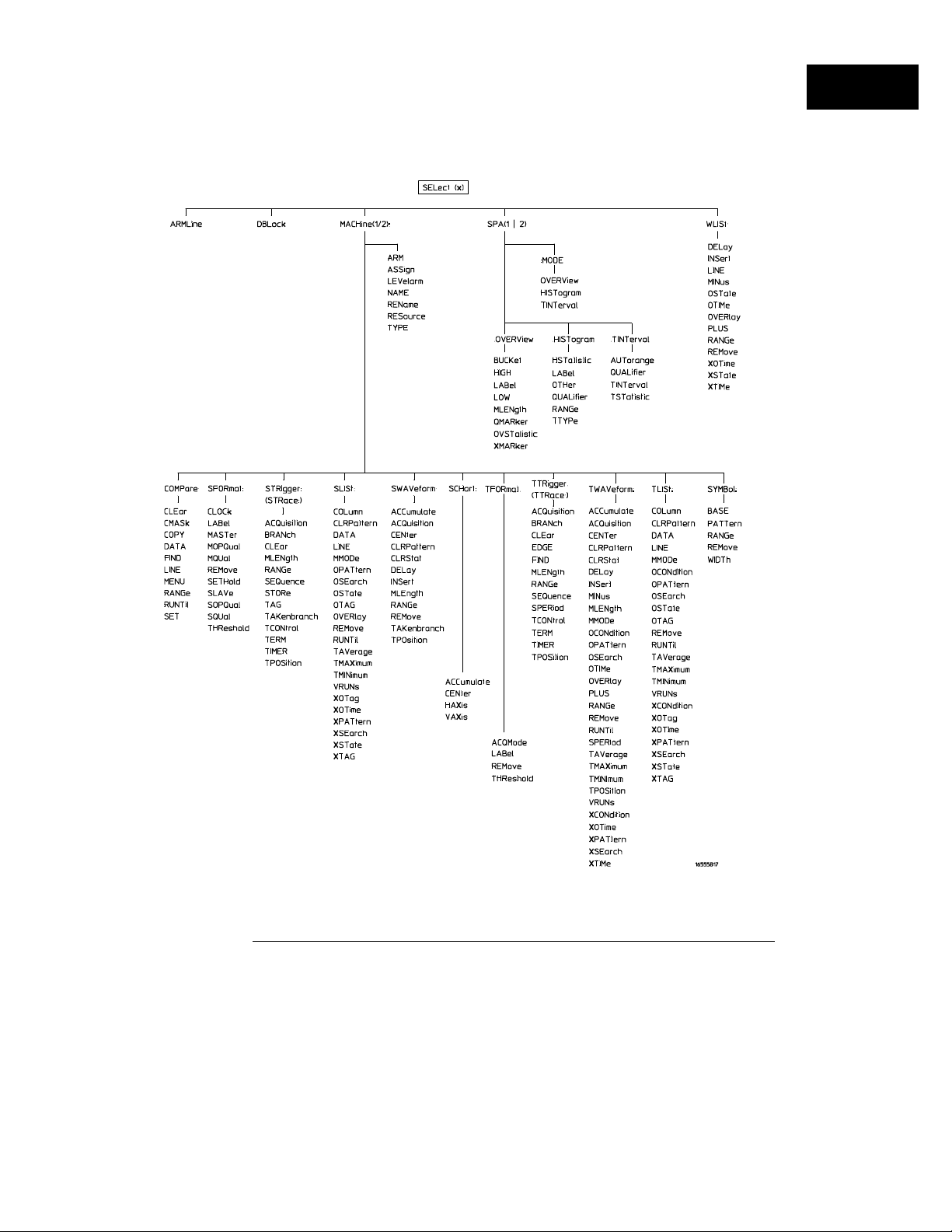
Figure 1-1
Programming the 16557D
Command Set Organization
16557D Command Tree
1–9
Page 28

Programming the 16557D
Command Set Organization
Table 1-1
Alphabetical Command-to-Subsystem Directory
Command Where Used
ACCumulate SCHart, SWAVeform, TWAVeform
ACQMode TFORmat
ACQuisition STRigger, SWAVeform, TTRigger,
TWAVeform
ARM MACHine
ARMLine Module Level Commands
ASSign MACHine
AUTorange SPA
BASE SYMBol
BRANch STRigger, TTRigger
BUCKet SPA
CENter SCHart, SWAVeform, TWAVeform
CLEar COMPare, STRigger, TTRigger
CLOCk SFORmat
CLRPattern SLISt, SWAVeform, TLISt, TWAVeform
CLRStat SWAVeform, TWAVeform
CMASk COMPare
COLumn SLISt, TLISt
COPY COMPare
DATA COMPare, SLISt, TLISt
DBLock Module Level Commands
DELay SWAVeform, TWAVeform, WLISt
EDGE TTRigger
FIND COMPare, STRigger, TTRigger
HAXis SCHart
HIGH SPA
HISTatistic SPA
HISTogram SPA
INSert SWAVeform, TWAVeform, WLISt
LABel SFORmat, SPA, TFORmat
LEVelarm MACHine
LINE COMPare, SLISt, TLISt, WLISt
LOW SPA
MASTer SFORmat
MENU COMPare
MINus TWAVeform, WLISt
MLENgth SPA, STRigger, SWAVeform, TTRigger,
TWAVeform
MMODe SLISt, TLISt, TWAVeform
MODE SPA
Command Where Used
MOPQual SFORmat
MQUal SFORmat
NAME MACHine
OCONdition TLISt, TWAVeform
OMARker SPA
OPATtern SLISt, TLISt, TWAVeform
OSEarch SLISt, TLISt, TWAVeform
OSTate SLISt, TLISt, WLISt
OTAG SLISt, TLISt
OTHer SPA
OTIMe TWAVeform, WLISt
OVERlay SLISt, TWAVeform, WLISt
OVERView SPA
OVSTatistic SPA
PATTern SYMBol
PLUS TWAVeform, WLISt
QUALifier SPA
RANGe COMPare, SPA, STRigger, SWAVeform,
SYMBol, TFORmat, TWAVeform, WLISt
REMove SFORmat, SLISt, SWAVeform, SYMBol,
TFORmat, TLISt, TWAVeform, WLISt
REName MACHine
RESource MACHine
RUNTil COMPare, SLISt, TLISt, TWAVeform
SEQuence STRigger, TTRigger
SET COMPare
SETHold SFORmat
SLAVe SFORmat
SOPQual SFORmat
SPERiod TFORmat, TWAVeform
SETHold SFORmat
SLAVe SFORmat
SOPQual SFORmat
SPERiod TFORmat, TWAVeform
SQUal SFORmat
STORe STRigger
TAG STRigger
TAKenbranch STRigger, SWAVeform
TAVerage SLISt, TLISt, TWAVeform
1–10
Page 29

Table 1-1, continued
Alphabetical Command-to-Subsystem Directory, continued
Programming the 16557D
Command Set Organization
Command Where Used
TCONtrol STRigger, TTRigger
TERM STRigger, TTRigger
THReshold SFORmat, TFORmat
TIMER STRigger, TTRigger
TINTerval SPA
TMAXimum SLISt, TLISt, TWAVeform
TMINimum SLISt, TLISt, TWAVeform
TPOSition STRigger, SWAVeform, TTRigger,
TWAVeform
TSTatistic SPA
TTYPe SPA
TYPE MACHine
Command Where Used
VAXis SCHart
VRUNs SLISt, TLISt, TWAVeform
WIDTh SYMBol
XCONdition TLISt, TWAVeform
XMARker SPA
XOTag SLISt, TLISt
XOTime SLISt, TLISt, TWAVeform, WLISt
XPATtern SLISt, TLISt, TWAVeform
XSEarch SLISt, TLISt, TWAVeform
XSTate SLISt, TLISt, WLISt
XTAG SLISt, TLISt
XTIMe TWAVeform, WLISt
1–11
Page 30
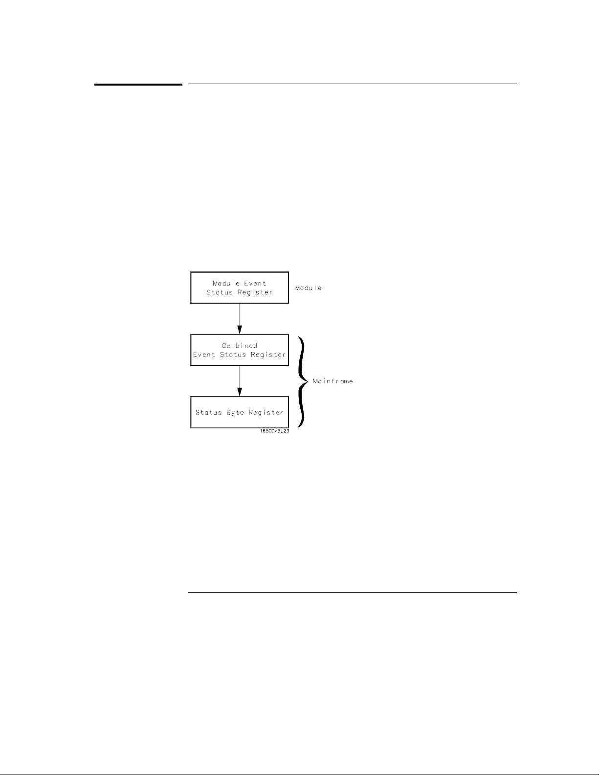
Figure 1-2
Programming the 16557D
Module Status Reporting
Module Status Reporting
Each module reports its status to the Module Event Status Register
(MESR<N>), which in turn reports to the Combined Event Status Register
(CESR) in the Agilent Technologies 16500/16501A mainframe (see
Technologies 16500/16501A Programmer’s Guide
Event Status Register is enabled by the Module Event Status Enable Register
(MESE<N>).
The MESE<N> and MESR<N> instructions are not used in conjunction with
the SELect command, so they are not listed in the 16557D’s command tree.
The following descriptions of the MESE<N> and MESR<N> instructions
provide the module specific information needed to enable and interpret the
contents of the registers.
chapter 6). The Module
Agilent
Module Status Reporting
1–12
Page 31

MESE<N>
Programming the 16557D
MESE<N>
Command
<enable_mask>
Example
Query
:MESE <N> <enable_mask>
The MESE<N> command sets the Module Event Status Enable register bits.
The MESE register contains a mask value for the bits enabled in the MESR
register. A one in the MESE will enable the corresponding bit in the MESR, a
zero will disable the bit.
The first parameter <N> specifies the module. The second parameter
specifies the enable value.
Refer to table 1-2 for information about the Module Event Status register bits,
bit weights, and what each bit masks for the module. Complete information
for status reporting is in chapter 6 of the
16500/16501A Programmer’s Guide
<N> {1|2|3|4|5|6|7|8|9|10}
refers to slot A, and so on.
integer from 0 to 255
OUTPUT XXX;":MESE5 1"
:MESE<N>?
Agilent Technologies
manual.
number of slot in which the module resides. 1
Returned Format
Example
The MESE query returns the current setting.
[:MESE<N>]<enable_mask><NL>
10 OUTPUT XXX;":MESE5?"
20 ENTER XXX; Mes
30 PRINT Mes
40 END
1–13
Page 32

Programming the 16557D
MESE<N>
Table 1-2 Module Event Status Enable Register (A "1" enables the MESR bit)
Bit Weight Enables
7 128 Not used
6 64 Not used
5 32 Not used
4 16 Not used
3 8 Pattern searches failed
2 4 Trigger found
1 2 RNT-Run until satisfied
0 1 MC-Measurement complete
The Module Event Status Enable Register contains a mask value for the bits
to be enabled in the Module Event Status Register (MESR). A one in the
MESE enables the corresponding bit in the MESR, and a zero disables the bit.
1–14
Page 33

MESR<N>
Programming the 16557D
MESR<N>
Query
Returned Format
<status>
Example
:MESR<N>?
The MESR<N> query returns the contents of the Module Event Status
register. When you read the MESR, the value returned is the total bit weights
of all bits that are set at the time the register is read. Reading the register
clears the Module Event Status Register.
Table 1-3 shows each bit in the Module Event Status Register and its bit
weight for this module.
The parameter 1 through 10 refers to the module in slot A through J
respectively.
[MESR<N>]<status><NL>
<N> {1|2|3|4|5|6|7|8|9|10}
integer from 0 to 255
10 OUTPUT XXX;":MESR5?"
20 ENTER XXX; Mer
30 PRINT Mer
40 END
number of slot in which the module resides
1–15
Page 34

Programming the 16557D
MESR<N>
Table 1-3 Module Event Status Register
Bit Weight Condition
7 128 Not used
6 64 Not used
5 32 Not used
4 16 Not used
3 8 1 = One or more pattern searches failed
2 4 1 = Trigger found
1 2 1 = Run until satisfied
0 1 1 = Measurement complete
0 = Pattern searches did not fail
0 = Trigger not found
0 = Run until not satisfied
0 = Measurement not complete
1–16
Page 35
2
Module Level Commands
Page 36

Introduction
The logic analyzer module level commands access the global
functions of the 16557D logic analyzer module. These commands are:
• ARMLine
• DBLock
• MACHine
• SPA
• WLISt
2–2
Page 37
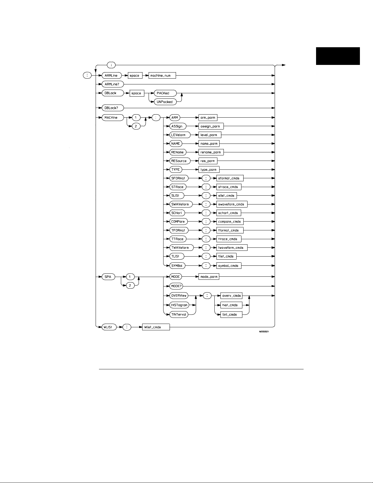
Figure 2-1
Module Level Commands
Module Level Syntax Diagram
2–3
Page 38

Module Level Commands
Table 2-1 Module Level Parameter Values
Parameter Type of Parameter or Command Reference
machine_num
arm_parm arm parameters see chapter 3
assign_parm assignment parameters see chapter 3
level_parm level parameters see chapter 3
name_parm name parameters see chapter 3
rename_parm rename parameters see chapter 3
res_parm resource parameters see chapter 3
type_parm type parameters see chapter 3
sformat_cmds state format subsystem commands see chapter 5
strace_cmds state trace subsystem commands see chapter 6
slist_cmds state list subsystem commands see chapter 7
swaveform_cmds state waveform subsystem commands see chapter 8
schart_cmds state chart subsystem commands see chapter 9
compare_cmds compare subsystem commands see chapter 10
tformat_cmds timing format subsystem commands see chapter 11
ttrace_cmds timing trace subsystem commands see chapter 12
twaveform_cmds timing waveform subsystem
tlist_cmds timing listing subsystem commands see chapter 14
symbol_cmds symbol subsystem commands see chapter 15
mode_parm SPA mode parameters see chapter 16
overv_cmds SPA overview commands see chapter 16
hist_cmds SPA histogram commands see chapter 16
tint_cmds SPA time interval commands see chapter 16
Wlist_cmds waveforms/listing commands see chapter 4
MACHin e{1|2}
commands
see chapter 13
2–4
Page 39

ARMLine
Module Level Commands
ARMLine
Command
Example
Query
Returned Format
Example
:ARML ine MACHine<N>
The ARMLine command selects which machine generates the arm out signal
on the IMB (intermodule bus). This command is only valid when two
analyzers are on. However, the query is always valid.
<N> {1|2}
OUTPUT XXX;":ARMLINE MACHINE1"
:ARMLine?
If the analyzer is set up for OR’d triggering, then the ARMLine query returns
an empty string. This cannot be used for setting up OR’d triggering.
[:ARMLine]{MACHine<N>|}<NL>
OUTPUT XXX;":ARMLine?"
DBLock
Command
:DBLoc k {PACKed | UNPacked }
The DBLock command specifies the data block format that is contained in
the response from a :SYSTem:DATA? query. See Chapter 17 for more
information on the :SYSTem:DATA command and query.
The PACKed option (default) uploads data in a compressed format. This
option is used to upload data for archiving, or for reloading back into the
analyzer. When an analyzer configuration is saved to disk, the PACKed data
format is always used (regardless of the current DBLock selection).
2–5
Page 40

Module Level Commands
MACHine
The UNPacked option uploads data in a format that is easy to interpret and
process. The UNPacked format cannot be downloaded back into the analyzer.
Example
Query
Returned Format
Example
Command
OUTPUT XXX;":DBLOCK PACKED"
:DBLock?
The DBLock query returns the current data block format selection.
[:DBLock]{PACKed | UNPacked}<NL>
OUTPUT XXX;":DBLock?"
MACHine
:MACHine<N>
The MACHine command selects which of the two machines (analyzers) the
subsequent commands or queries will refer to. MACHine is also a subsystem
containing commands that control the logic analyzer system level functions.
Examples include pod assignments, analyzer names, and analyzer type. See
chapter 3 for details about the MACHine subsystem.
<N> {1|2}
Example
OUTPUT XXX;":MACHINE1:NAME ’DRAMTEST’"
2–6
Page 41

SPA
Module Level Commands
SPA
Command
Example
Command
:SPA<N>
The SPA command selects which of the two analyzers the subsequent
commands or queries will refer to. SPA is also a subsystem containing
commands that control the logic analyzer SPA functions. See chapter 16 for
details about the SPA subsystem.
<N> {1|2}
OUTPUT XXX;":SPA1:MODE OVERVIEW"
WLISt
:WLISt
The WLISt selector accesses the commands used to place markers and query
marker positions in Timing/State Mixed mode. The WLISt subsystem also
contains commands that allows you to insert waveforms from other
time-correlated machines and modules. The details of the WLISt subsystem
are in chapter 4.
Example
OUTPUT XXX;":WLIST:OTIME 40.0E−6"
2–7
Page 42

2–8
Page 43
Part 2
MACHine Subsystem
3
WLISt Subsystem
4
SFORmat Subsystem
5
STRigger (STRace) Subsystem
6
SLISt Subsystem
7
SWAVeform Subsystem
8
SCHart Subsystem
9
COMPare Subsystem
10
TFORmat Subsystem
11
TTRigger (TTRace) Subsystem
12
TWAVeform Subsystem
13
TLISt Subsystem
14
SYMBol Subsystem
15
SPA Subsystem
16
DATA and SETup Commands
17
Commands
Page 44

Page 45
3
MACHine Subsystem
Page 46

Introduction
The MACHine subsystem contains the commands that control the
machine level of operation of the logic analyzer. Some of the functions
are normally found in the Trigger menu. These commands are:
• ARM
• LEVelarm
The functions of three of these commands reside in the State/Timing
Configuration menu. These commands are:
• ASSign
• NAME
• TYPE
Even though the functions of the following commands reside in the
Format menu they are at the machine level of the command tree and
are therefore located in the MACHine subsystem. These commands
are:
• REName
• RESource
3–2
Page 47
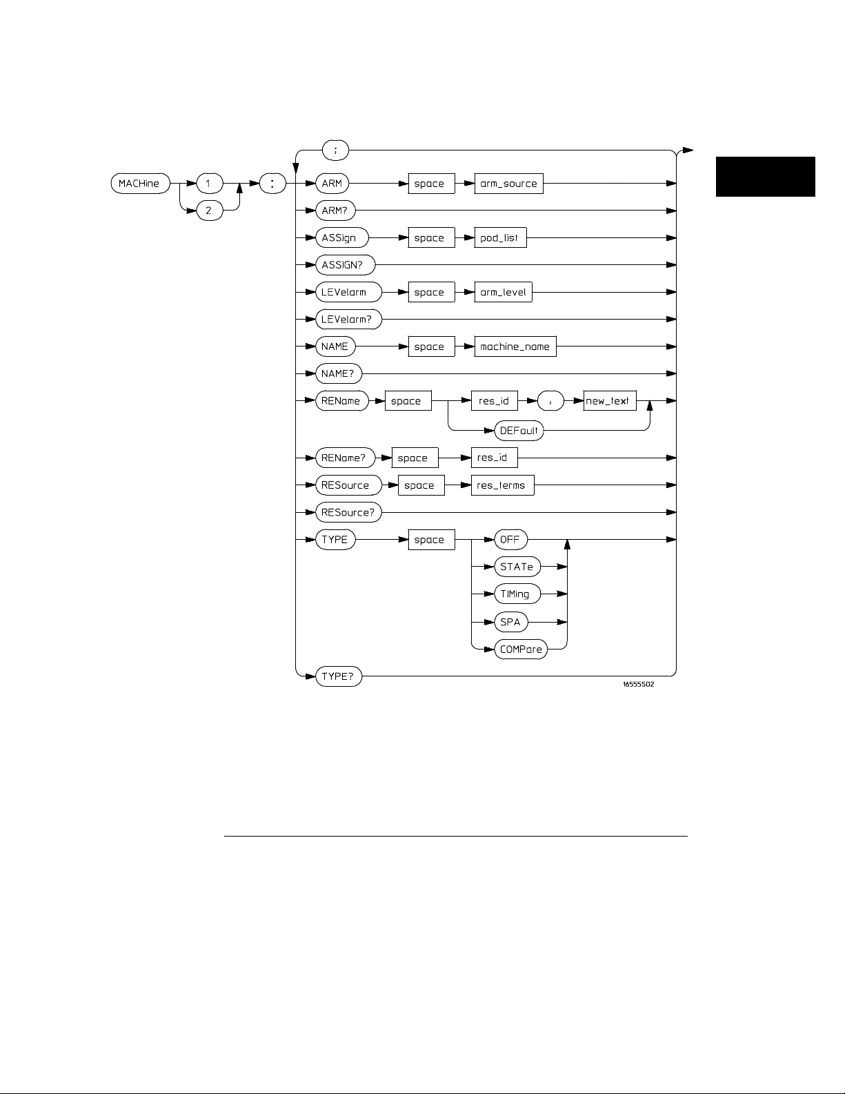
Figure 3-1
MACHine Subsystem
Machine Subsystem Syntax Diagram
3–3
Page 48

MACHine Subsystem
MACHine
Table 3-1 Machine Subsystem Parameter Values
Parameter Value
arm_source
pod_list
pod_num integer from 1 to 12
arm_level integer from 1 to 11 representing sequence level
machine_name string of up to 10 alphanumeric characters
res_id
new_text string of up to 8 alphanumeric characters
state_terms
res_terms
{RUN | INTermodule | MACHine {1|2}}
{NONE | <p od _n um>[, <pod _num>]...}
{<stat e_terms>}
or
{<stat e_terms>|EDGE{1|2}}
{A|B|C|D|E|F|G|H|I|J|
RANGE{1|2}|TIMER{1|2}}
{<res_id>[,<res_id>]...}
for state analyzer
for timing analyzer
Selector
Example
MACHine
:MACHine<N>
The MACHine <N> selector specifies which of the two analyzers (machines)
available in the module the commands or queries following will refer to.
Because the MACHine<N> command is a root level command, it will normally
appear as the first element of a compound header.
<N> {1|2}
OUTPUT XXX; ":MACHINE1:NAME ’TIMING’"
(the machine number)
3–4
Page 49

ARM
MACHine Subsystem
ARM
Command
<arm_source> {RUN|INTermodule|MACHine{1|2}}
Example
Query
Returned Format
:MACHi ne{1|2}:ARM <arm _source>
The ARM command specifies the arming source of the specified analyzer
(machine). The RUN option disables the arm source. For example, if you do
not want to use either the intermodule bus or the other machine to arm the
current machine, you specify the RUN option.
If you are using an Agilent Technologies 16500C mainframe, you can set up
OR’d Triggering by arming the module from INTermodule when intermodule
is set to Group Run with OR TRIGGER. See the
16500C Programmer’s Guide
OUTPUT XXX;":MACHINE1:ARM MACHINE2"
for details.
:MACHine{1|2}:ARM?
The ARM query returns the source that the current analyzer (machine) will
be armed by.
[:MACH in e{ 1|2}:ARM ] <arm_source>
Agilent Technologies
Example
OUTPUT XXX;":MACHINE1:ARM?"
3–5
Page 50

MACHine Subsystem
ASSign
ASSign
Command
<pod_list> {NONE | <pod #>[, <pod #>]...}
<pod#>
Example
Query
Returned Format
:MACHine{1|2}:ASSign <pod_list>
The ASSign command assigns pods to a particular analyzer (machine). The
ASSign command will assign two pods for each pod number you specify
because pods must be assigned to analyzers in pairs. NONE clears all pods
from the specified analyzer (machine) and places them in the "unassigned"
category.
If you specify a pod number greater than currently available, the logic
analysis system generates an "Argument out of range" error.
an integer from 1 to 12
This example assigns pod pairs 1/2 and 5/6 to machine 1:
OUTPUT XXX;":MACHINE1:ASSIGN 5, 2, 1"
:MACHine{1|2}:ASSign?
The ASSign query returns which pods are assigned to the current analyzer
(machine).
[:MACHine{1|2}:ASSign] <pod_list><NL>
Example
OUTPUT XXX;":MACHINE1:ASSIGN?"
3–6
Page 51

LEVelarm
MACHine Subsystem
LEVelarm
Command
<arm_level>
Example
Query
Returned Format
Example
:MACHine{1|2}:LEVelarm <arm_level>
The LEVelarm command allows you to specify the sequence level for a
specified machine that will be armed by the Intermodule Bus or the other
machine. This command is only valid if the specified machine is on and the
arming source is not set to RUN with the ARM command.
integer from 1 to 11 representing sequence level
OUTPUT XXX;":MACHINE1:LEVELARM 2"
:MACHine{1|2}:LEVelarm?
The LEVelarm query returns the current sequence level receiving the arming
for a specified machine.
[:MACHine{1|2}:LEVelarm] <arm_level><NL>
OUTPUT XXX;":MACHINE1:LEVELARM?"
3–7
Page 52

MACHine Subsystem
NAME
NAME
Command
<machine_name>
Example
Query
Returned Format
Example
:MACHine{1|2}:NAME <machine_name>
The NAME command allows you to assign a name of up to 10 characters to a
particular analyzer (machine) for easier identification. Spaces are valid
characters.
string of up to 10 alphanumeric characters
OUTPUT XXX;":MACHINE1:NAME ’DRAM TEST’"
:MACHine{1|2}:NAME?
The NAME query returns the current analyzer name as an ASCII string.
[:MACHine{1|2}:NAME] <machine name><NL>
OUTPUT XXX;":MACHINE1:NAME?"
REName
Command
:MACH ine{1|2}:REName {{<r es_id>, <new_text>} |
DEFault}
The REName command allows you to assign a specific name of up to eight
characters to terms A through J, Range 1 and 2, Timer 1 and 2, and Edge 1
and 2. The terms do not have to be assigned to the specified machine. The
DEFault option sets all resource term names to the default names assigned
when turning on the instrument.
3–8
Page 53

MACHine Subsystem
RESource
<res_id> {<state_terms>}
{<state_terms>|EDGE{1|2}}
<new_text>
<state_terms> {A|B|C|D|E|F|G|H|I|J| RANGe1 | RANGe2 | TIMer1 | TIMer2}
Example
Query
Returned Format
Example
string of up to 8 alphanumeric characters
OUTPUT XXX;":MACHINE1:RENAME A,’DATA’"
:MACHi ne{1|2}:RENAME ? <res_id>
The REName query returns the current names for specified terms assigned
to the specified analyzer.
[:MACHine{1|2}:RENAME] <res_id>,<new_text><NL>
OUTPUT XXX;":MACHINE1:RENAME? D"
for state analyzer
for timing analyzer
RESource
Command
<res_id> <state_terms>
<state_terms> {A|B|C|D|E|F|G|H|I|J|RANGe1| RANGe2 | TIMer1|TIMer2}
:MACH ine{1|2}:RESource {< res_id>[,<res_id>]...}
The RESource command allows you to assign resource terms A through J,
Range 1 and 2, and Timer 1 and 2 to a particular analyzer.
In the timing analyzer only, two additional resource terms are available.
These terms are Edge 1 and 2. These terms are always assigned to the
machine that is configured as the timing analyzer.
for state analyzer
{<state_terms>|EDGE{1|2}}
for timing analyzer
3–9
Page 54

MACHine Subsystem
TYPE
Example
Query
Returned Format
Example
Command
OUTPUT XXX;":MACHINE1:RESOURCE A,C,RANGE1"
:MACHine{1|2}:RESOURCE?
The RESource query returns the current resource terms assigned to the
specified analyzer. If no resource terms are assigned, no <res_id> is returned.
[:MACHine{1|2}:RESOURCE] <res_id>[,<res_id>,...]<NL>
OUTPUT XXX;":MACHINE1:RESOURCE?"
TYPE
:MACHine{1|2}:TYPE <analyzer type>
The TYPE command specifies what type a specified analyzer (machine) will
be. The analyzer types are state or timing. State Compare (COMPare) and
SPA are considered to be state analyzers because they use an external clock,
but need to specified as COMPare or SPA.
The TYPE command also allows you to turn off a particular machine.
Only one timing analyzer can be specified at a time.
Example
<analyzer
type>
{OFF|COMPare|SPA|STATe|TIMing}
OUTPUT XXX;":MACHINE1:TYPE STATE"
3–10
Page 55

MACHine Subsystem
TYPE
Query
Returned Format
Example
:MACHine{1|2}:TYPE?
The TYPE query returns the current analyzer type for the specified analyzer.
[:MACHine{1|2}:TYPE] <analyzer type><NL>
OUTPUT XXX;":MACHINE1:TYPE?"
3–11
Page 56

3–12
Page 57
4
WLISt Subsystem
Page 58

Introduction
The commands in the WLISt (Waveforms/LISting) subsystem control
the X and O marker placement on the waveforms portion of the
Timing/State mixed mode display. The XSTate and OSTate queries
return what states the X and O markers are on. Because the markers
can only be placed on the timing waveforms, the queries return what
state (state acquisition memory location) the marked pattern is stored
in.
In order to have mixed mode, one machine must be a state analyzer
with time tagging on (use
• DELay
• INSert
• LINE
• MINus
• OSTate
• OTIMe
MACHin e<N>:STRigger:TAG TI ME
).
• OVERlay
• PLUS
• RANGe
• REMove
• XOTime
• XSTate
• XTIMe
4–2
Page 59
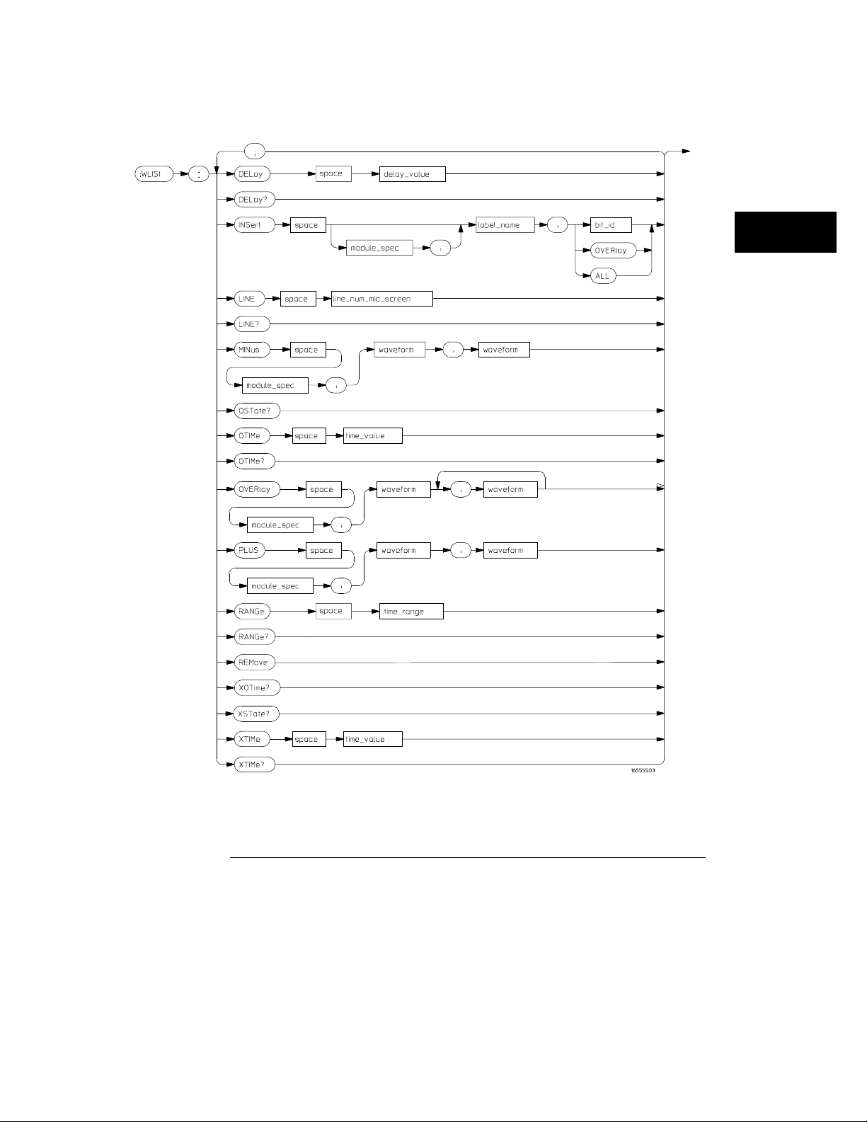
Figure 4-1
WLISt Subsystem
WLISt Subsystem Syntax Diagram
4–3
Page 60

WLISt Subsystem
WLISt
Table 4-1 WLISt Subsystem Parameter Values
Parameter Value
delay_value real number between -2500 s and +2500 s
module_spec
bit_id integer from 0 to 31
label_name string of up to 6 alphanumeric characters
line_num_mid_screen integer from -2080768 to +2080768
waveform
acquisition_spec
time_value real number
time_range real number between 10 ns and 10 ks
{1|2|3 |4|5|6|7|8|9|10}
is installed)
string containing
{A|B|C|D|E|F|G|H|I|J}
WLISt
(slot where master card
<acquisition_spec>{1|2}
Selector
Example
:WLISt
The WLISt (Waveforms/LISting) selector is used as a part of a compound
header to access the settings normally found in the Mixed Mode menu.
Because the WLISt command is a root-level command, it will always appear
as the first element of a compound header.
The WLISt subsystem is only available when one or more state analyzers with
time tagging on are specified.
OUTPUT XXX;":WLIST:XTIME 40.0E−6"
4–4
Page 61

DELay
WLISt Subsystem
DELay
Command
<delay_value>
Example
Query
Returned Format
Example
:WLISt:DELay <delay_value>
The DELay command specifies the amount of time between the timing
trigger and the horizontal center of the the timing waveform display. The
allowable values for delay are −2500 s to +2500 s.
real number between −2500 s and +2500 s
OUTPUT XXX;":WLIST:DELAY 100E−6"
:WLISt:DELay?
The DELay query returns the current time offset (delay) value from the
trigger.
[:WLISt:DELay] <delay_value><NL>
OUTPUT XXX;":WLIST:DELAY?"
4–5
Page 62

WLISt Subsystem
INSert
INSert
Command
:WLISt :INSert [<module _spec>,]<label_name>
[,{<bi t_id>|OVERlay| ALL}]
The INSert command inserts waveforms in the timing waveform display. The
waveforms are added from top to bottom up to a maximum of 96 waveforms.
Once 96 waveforms are present, each time you insert another waveform, it
replaces the last waveform.
Time-correlated waveforms from the oscilloscope and another logic analyzer
module can also be inserted in the logic analyzer’s timing waveforms display.
Oscilloscope waveforms occupy the same display space as three logic
analyzer waveforms. When inserting waveforms from the oscilloscope or
another logic analyzer module, the optional first parameter must be used,
which is the module specifier. 1 through 10 corresponds to modules A
through J. If you do not specify the module, the selected module is assumed.
The second parameter specifies the label name that will be inserted. The
optional third parameter specifies the label bit number, overlay, or all. If a
number is specified, only the waveform for that bit number is added to the
screen.
If you specify OVERlay, all the bits of the label are displayed as a composite
overlaid waveform. If you specify ALL, all the bits are displayed sequentially.
If you do not specify the third parameter, ALL is assumed.
<module_spec> {1|2|3|4|5|6|7|8|9|10}
<label_name>
<bit_id>
Example
string of up to 6 alphanumeric characters
integer from 0 to 31
OUTPUT XXX;":WLIST:INSERT 3, ’WAVE’,9"
4–6
Page 63

Inserting Oscilloscope Waveforms
WLISt Subsystem
LINE
Command
<module_spec> {1|2|3|4|5|6|7|8|9|10}
<label_name>
Example
:WLISt :INSert <module_ spec>,<label_name>
This inserts a waveform from an oscilloscope to the timing waveforms display.
string of one alpha and one numeric character, identical to that on the
oscilloscope waveform display.
OUTPUT XXX;":WLIST:INSERT 3, ’C1’"
LINE
Command
<line_num_mid_
screen>
:WLISt :LINE <line_num_ mid_screen>
The LINE command allows you to scroll the timing analyzer listing vertically.
The command specifies the state line number relative to the trigger. The
analyzer then highlights the specified line at the center of the screen.
integer from -2080768 to +2080768.
slot in which master card is installed
Example
OUTPUT XXX;":WLIST:LINE 0"
4–7
Page 64
WLISt Subsystem
MINus
Query
Returned Format
Example
Command
:WLISt:LINE?
The LINE query returns the line number for the state currently in the data
listing roll box at center screen.
[:WLIS t: LI NE] <line_ num_mid_screen><NL>
OUTPUT XXX;":WLIST:LINE?"
MINus
:WLIS t:MINus <module_spec >,<waveform>,<waveform>
The MINus command inserts time-correlated A−B (A minus B) oscilloscope
waveforms on the screen. The first parameter is the module specifier where
the oscilloscope module resides, where 1 through 10 refers to slots A through
J. The next two parameters specify which waveforms will be subtracted from
each other.
MINus only inserts oscilloscope waveforms. It cannot be used with analyzer
waveforms.
<module_spec> {1|2|3|4|5|6|7|8|9|10}
<waveform>
<acquisition_
spec>
Example
string containing
{A|B|C|D|E|F|G|H|I|J}
OUTPUT XXX; ":WLIST:MINUS 1,’A1’,’A2’"
4–8
<acquisition_spec>{1|2}
(slot where master card is located)
(slot where acquisition card is located)
Page 65

OSTate
WLISt Subsystem
OSTate
Query
Returned Format
<state_num>
Example
Command
<time_value>
Example
:WLISt:OSTate?
The OSTate query returns the state where the O marker is positioned. If data
is not valid, the query returns 2147483647.
[:WLIS t: OS Tate] <sta te_num><NL>
integer
OUTPUT XXX;":WLIST:OSTATE?"
OTIMe
:WLISt:OTIMe <time_value>
The OTIMe command positions the O marker on the timing waveforms in the
mixed mode display. If the data is not valid, the command performs no
action.
real number
OUTPUT XXX;":WLIST:OTIME 40.0E−6"
4–9
Page 66
WLISt Subsystem
OVERlay
Query
Returned Format
Example
Command
:WLISt:OTIMe?
The OTIMe query returns the O marker position in time. If data is not valid,
the query returns 9.9E37.
[:WLISt:OTIMe] <time_value><NL>
OUTPUT XXX;":WLIST:OTIME?"
OVERlay
:WLIS t:OVERlay <module_nu mber>,<label>
[,<label>]...
The OVERlay command overlays two or more oscilloscope waveforms and
adds the resultant waveform to the current waveform display. The first
parameter of the command syntax specifies which slot contains the
oscilloscope time base card. The next parameters are the labels of the
waveforms that are to be overlaid.
Overlay only inserts oscilloscope waveforms. It cannot be used with analyzer
waveforms.
<module_spec> {1|2|3|4|5|6|7|8|9|10}
<waveform>
<acquisition_
spec>
Example
string containing
{A|B|C|D|E|F|G|H|I|J}
OUTPUT XXX;":WLIST:OVERLAY 3, ’C1’,’B1’"
4–10
<acquisition_spec>{1|2}
(slot where master card is located)
(slot where acquisition card is located)
Page 67

PLUS
WLISt Subsystem
PLUS
Command
<module_spec> {1|2|3|4|5|6|7|8|9|10}
<waveform>
<acquisition_
spec>
Example
:WLISt :PLUS <module_sp ec>,<waveform>,<waveform>
The PLUS command inserts time-correlated A+B oscilloscope waveforms on
the screen. The first parameter specifies which slot is the oscilloscope
module. 1 through 10 refers to slots A through J. The next two parameters
specify which waveforms will be added to each other.
PLUS only inserts oscilloscope waveforms. It cannot be used with analyzer
waveforms.
string containing
{A|B|C|D|E|F|G|H|I|J}
OUTPUT XXX; ":WLIST:PLUS 1,’A1’,’A2’"
<acquisition_spec>{1|2}
(slot where master card is located)
(slot where acquisition card is located)
4–11
Page 68

WLISt Subsystem
RANGe
RANGe
Command
<time_range>
Example
Query
Returned Format
Example
:WLISt:RANGe <time_value>
The RANGe command specifies the full-screen time in the timing waveform
menu. It is equivalent to ten times the seconds per division setting on the
display. The allowable values for RANGe are from 10 ns to 10 ks.
real number between 10 ns and 10 ks
OUTPUT XXX;":WLIST:RANGE 100E−9"
:WLISt:RANGe?
The RANGe query returns the current full-screen time.
[:WLISt:RANGe] <time_value><NL>
OUTPUT XXX;":WLIST:RANGE?"
REMove
Command
Example
:WLISt:REMove
The REMove command deletes all waveforms from the display.
OUTPUT XXX;":WLIST:REMOVE"
4–12
Page 69

XOTime
WLISt Subsystem
XOTime
Query
Returned Format
<time_value>
Example
Query
Returned Format
<state_num>
:WLISt:XOTime?
The XOTime query returns the time from the X marker to the O marker. If
data is not valid, the query returns 9.9E37.
[:WLIS t: XO Time] <tim e_value><NL>
real number
OUTPUT XXX;":WLIST:XOTIME?"
XSTate
:WLISt:XSTate?
The XSTate query returns the state where the X marker is positioned. If data
is not valid, the query returns 2147483647.
[:WLIS t: XS Tate] <sta te_num><NL>
integer
Example
OUTPUT XXX;":WLIST:XSTATE?"
4–13
Page 70
WLISt Subsystem
XTIMe
XTIMe
Command
<time_value>
Example
Query
Returned Format
Example
:WLISt:XTIMe <time_value>
The XTIMe command positions the X marker on the timing waveforms in the
mixed mode display. If the data is not valid, the command performs no
action.
real number
OUTPUT XXX;":WLIST:XTIME 40.0E−6"
:WLISt:XTIMe?
The XTIMe query returns the X marker position in time. If data is not valid,
the query returns 9.9E37.
[:WLISt:XTIMe] <time_value><NL>
OUTPUT XXX;":WLIST:XTIME?"
4–14
Page 71
5
SFORmat Subsystem
Page 72

Introduction
The SFORmat subsystem contains the commands available for the
State Format menu in the 16557D logic analyzer module. These
commands are:
• CLOCk
• LABel
• MASTer
• MOPQual
• MQUal
• REMove
• SETHold
• SLAVe
• SOPQual
• SQUal
• THReshold
5–2
Page 73
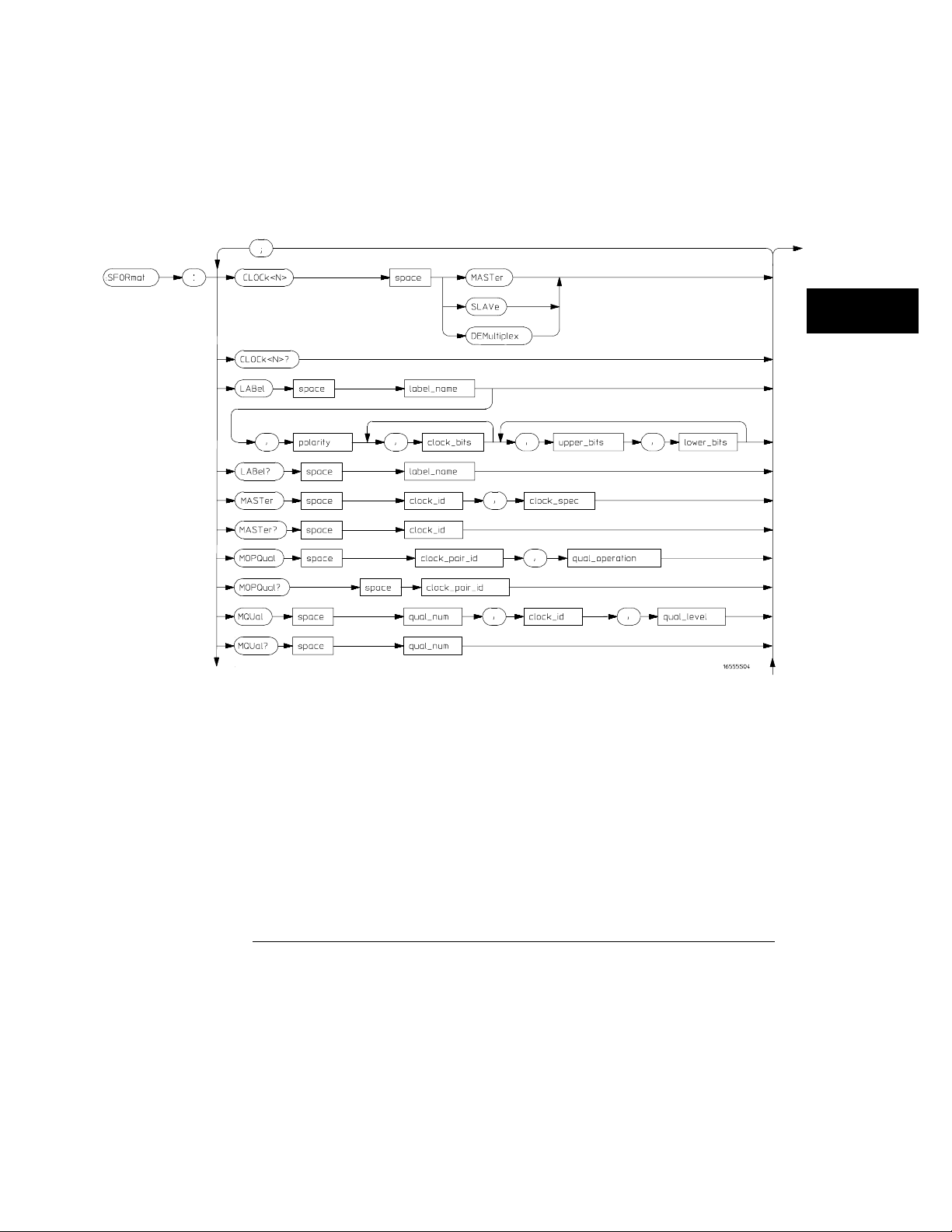
Figure 5-1
SFORmat Subsystem
SFORmat Subsystem Syntax Diagram
5–3
Page 74
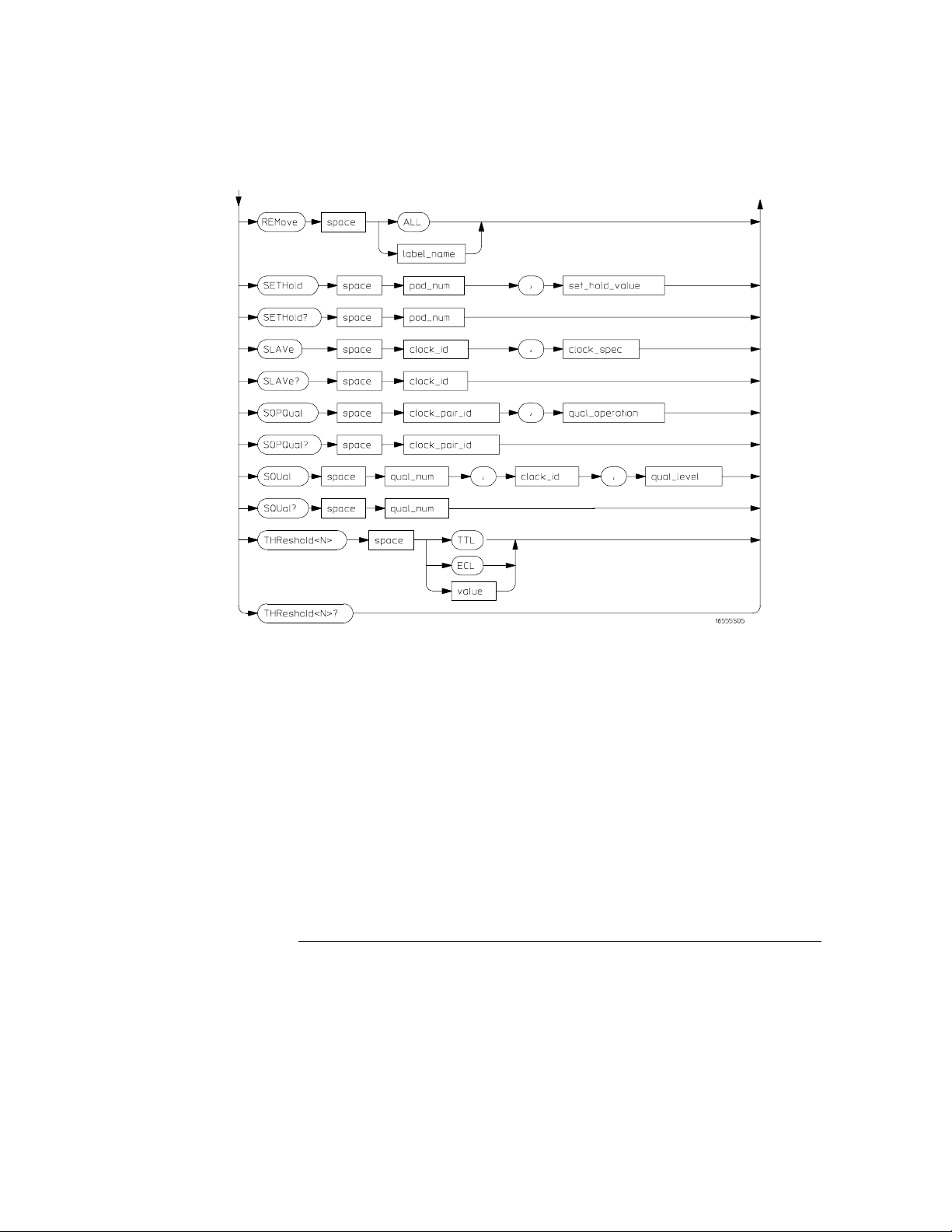
Figure 5-1 (continued)
SFORmat Subsystem
SFORmat Subsystem Syntax Diagram (continued)
5–4
Page 75

Table 5-1 SFORmat Subsystem Parameter Values
Parameter Value
<N> an integer from 1 to 12
label_name string of up to 6 alphanumeric characters
polarity
clock_bits format (integer from 0 to 65535) for a clock (clocks are assigned
upper_bits format (integer from 0 to 65535) for a pod (pods are assigned in
lower_bits format (integer from 0 to 65535) for a pod (pods are assigned in
clock_id
clock_spec
clock_pair_id
qual_operation
qual_num
qual_level
pod_num an integer from 1 to 12
set_hold_value
value voltage (real number) -6.00 to +6.00
{POSit iv e | NE Gative}
in decreasing order)
decreasing order)
decreasing order)
{J | K | L | M}
{OFF | RISing | FALLing | BOTH}
{1 | 2}
{AND|OR}
{1 | 2 | 3 | 4}
{OFF | LOW | HIGH}
{0 | 1 | 2 | 3 | 4 | 5 | 6 | 7 | 8 | 9}
SFORmat Subsystem
5–5
Page 76

SFORmat Subsystem
SFORmat
SFORmat
Selector
Example
Command
:MACHine{1|2}:SFORmat
The SFORmat (State Format) selector is used as a part of a compound
header to access the settings in the State Format menu. It always follows the
MACHine selector because it selects a branch directly below the MACHine
level in the command tree.
OUTPUT XXX;":MACHINE2:SFORMAT:MASTER J, RISING"
CLOCk
:MACHine{1|2}:SFORmat:CLOCk<N> <clock_mode>
The CLOCk command selects the clocking mode for a given pod when the
pod is assigned to the state analyzer. When the MASTer option is specified,
the pod will sample all channels on the master clock. When the SLAVe option
is specified, the pod will sample all channels on the slave clock. When the
DEMultiplex option is specified, only one pod of a pod pair can acquire data.
The bits of the selected pod will be clocked by the demultiplex master for
labels with bits assigned under the Master pod. The same bits will be clocked
by the demultiplex slave for labels with bits assigned under the Slave pod.
The master clock always follows the slave clock when both are used.
<N>
an integer from 1 to 12
<clock_mode> {MASTer | SLAVe | DEMultiplex}
Example
OUTPUT XXX;":MACHINE1:SFORMAT:CLOCK2 MASTER"
5–6
Page 77

SFORmat Subsystem
LABel
Query
Returned Format
Example
Command
:MACHine{1|2}:SFORmat:CLOCk<N>?
The CLOCk query returns the current clocking mode for a given pod.
[:MACHine{1|2}:SFORmat:CLOCK<N>] <clock_mode><NL>
OUTPUT XXX; ":MACHINE1:SFORMAT:CLOCK2?"
LABel
:MACHi ne{1|2}:SFORma t:LABel <name>[,<polarity>,
<clock _bits>, <upper_b its>,<lower_bits>
[,<upp er_bits>,<lowe r_bits>]...]
The LABel command allows you to specify polarity and assign channels to
new or existing labels. If the specified label name does not match an existing
label name, a new label will be created.
The order of the pod-specification parameters is significant. The first one
listed will match the highest-numbered pod assigned to the machine you’re
using. Each pod specification after that is assigned to the next highestnumbered pod. This way the specifications match the left-to-right
descending order of the pods you see on the Format display. Not including
enough pod specifications results in the lowest numbered pod(s) being
assigned a value of zero (all channels excluded). If you include more pod
specifications than there are pods for that machine, the extra ones will be
ignored. However, an error is reported any time more than 22 pod
specifications are listed.
The polarity can be specified at any point after the label name.
Because pods contain 16 channels, the format value for a pod must be
between 0 and 65535 (2
each bit will correspond to a single channel. A "1" in a bit position means the
associated channel in that pod is assigned to the label. A "0" in a bit position
means the associated channel in that pod is excluded from the label. Leading
zeroes may be omitted. For example, assigning #B1111001100 is equivalent
to entering "......****..**.." through the touchscreen.
A label can not have a total of more than 32 channels assigned to it.
16
−
1). When giving the pod assignment in binary,
5–7
Page 78

SFORmat Subsystem
LABel
<name>
string of up to 6 alphanumeric characters
<polarity> {POSitive | NEGative}
<clock_bits>
format (integer from 0 to 65535) for a clock (clocks are assigned in
decreasing order)
<upper_bits>
<lower_bits>
format (integer from 0 to 65535) for a pod (pods are assigned in decreasing
order)
Example
510 OUTPUT XXX;":MACHINE2:SFORMAT:LABEL ’STAT’, POSITIVE, 0,127,40312"
520 OUTPUT XXX;":MACHINE2:SFORMAT:LABEL ’SIG 1’, #B11,#B0000000011111111,
#B0000000000000000 "
Query
:MACHine{1|2}:SFORmat:LABel? <name>
The LABel query returns the current specification for the selected (by name)
label. If the label does not exist, nothing is returned. The polarity is always
returned as the first parameter. Numbers are always returned in decimal
format. Label names are case-sensitive.
Returned Format
[:MACH in e{ 1|2}:SFO Rmat:LABel] <name>,<polarity>
[, <assignment>]...<NL>
Example
OUTPUT XXX;":MACHINE2:SFORMAT:LABEL? ’DATA’"
5–8
Page 79

MASTer
SFORmat Subsystem
MASTer
Command
:MACHine{1|2}:SFORmat:MASTer <clock_id>,
<clock_spec>
The MASTer clock command allows you to specify a master clock for a given
machine. The master clock is used in all clocking modes (Master, Slave, and
Demultiplexed). Each command deals with only one clock (J,K,L,M);
therefore, a complete clock specification requires four commands, one for
each clock. Edge specifications (RISing, FALLing, or BOTH) are ORed.
At least one clock edge must be specified.
<clock_id> {J|K|L|M}
<clock_spec> {OFF|RISing|FALLing|BOTH}
Example
Query
Returned Format
OUTPUT XXX;":MACHINE2:SFORMAT:MASTER J, RISING"
:MACHi ne{1|2}:SFORma t:MASTer? <clock_id>
The MASTer query returns the clock specification for the specified clock.
[:MACHine{1|2}:SFORmat:MASTer] <clock_id>,<clock_spec><NL>
Example
OUTPUT XXX;":MACHINE2:SFORMAT:MASTER? <clock_id>"
5–9
Page 80

SFORmat Subsystem
MOPQual
MOPQual
Command
<clock_pair_
<qual_
operation>
Example
Query
Returned Format
:MACHi ne{1|2}:SFORma t:MOPQual <clock_pair_id>,
<qual_ operation>
The MOPQual (master operation qualifier) command allows you to specify
either the AND or the OR operation between master clock qualifier pair 1/2,
or between master clock qualifier pair 3/4. For example, you can specify a
master clock operation qualifier 1 AND 2.
{1|2}
id>
{AND|OR}
OUTPUT XXX;":MACHINE1:SFORMAT:MOPQUAL 1,AND"
where 2 indicates qualifier pair 3/4.
:MACHine{1|2}:SFORmat:MOPQual? <clock_pair_id>
The MOPQual query returns the operation qualifier specified for the master
clock.
[:MACHine{1|2}:SFORmat:MOPQUal <clock_pair_id>]
<qual_operation><NL>
Example
OUTPUT XXX;":MACHine1:SFORMAT:MOPQUAL? 1"
5–10
Page 81

MQUal
SFORmat Subsystem
MQUal
Command
:MACHi ne{1|2}:SFORma t:MQUal <qual_num>,
<clock _id>,<qual_lev el>
The MQUal (master qualifier) command allows you to specify the level
qualifier for the master clock.
<qual_num> {1|2|3|4}
<clock_id> {J|K|L|M}
<qual_level> {OFF|LOW|HIGH}
Example
Query
Returned Format
Example
OUTPUT XXX;":MACHINE2:SFORMAT:MQUAL 1,J,LOW"
:MACHine{1|2}:SFORmat:MQUal? <qual_num>
The MQUal query returns the qualifier specified for the master clock.
[:MACH in e{ 1|2}:SFO Rmat:MQUal] <qual_level><NL>
OUTPUT XXX;":MACHINE2:SFORMAT:MQUAL? 1"
5–11
Page 82

SFORmat Subsystem
REMove
REMove
Command
Example
Command
<name>
:MACHine{1|2}:SFORmat:REMove {<name>|ALL}
The REMove command allows you to delete all labels or any one label for a
given machine.
string of up to 6 alphanumeric characters
OUTPUT XXX;":MACHINE1:SFORMAT:REMOVE ’A’"
OUTPUT XXX;":MACHINE2:SFORMAT:REMOVE ALL"
SETHold
:MACHine{1|2}:SFORmat:SETHold
<pod_num>,<set_hold_value>
The SETHold (setup/hold) command allows you to set the setup and hold
specification for the state analyzer.
Even though the command requires integers to specify the setup and hold,
the query returns the current settings in a string. For example, if you send
the integer 0 for the setup and hold value, the query will return 3.0/0.0 ns as
an ASCII string when you have one clock and one edge specified.
5–12
Page 83

SFORmat Subsystem
SETHold
<set_hold_
Table 5-2
Example
<pod_num>
value>
an integer from 1 to 12
integer
{0|1|2|3|4|5|6|7|8|9}
representing the following setup and
hold values:
Setup and hold values
For one clock and one edge For one clock and both edges Multiple Clocks
0 = 3.0/0.0 ns 0 = 3.5/0.0 0 = 4.0/0.0
1 = 2.5/0.5 ns 1 = 3.0/0.5 1 = 3.5/0.5
2 = 2.0/1.0 ns 2 = 2.5/1.0 2 = 3.0/1.0
3 = 1.5/1.5 ns 3 = 2.0/1.5 3 = 2.5/1.5
4 = 1.0/2.0 ns 4 = 1.5/2.0 4 = 2.0/2.0
5 = 0.5/2.5 ns 5 = 1.0/2.5 5 = 1.5/2.5
6 = 0.0/3.0 ns 6 = 0.5/3.0 6 = 1.0/3.0
7 = -0.5/3.5 ns 7 = 0.0/3.5 7 = 0.5/3.5
N/A 8 = -0.5/4.0 8 = 0.0/4.0
N/A N/A 9 = -0.5/4.5
OUTPUT XXX;":MACHINE2:SFORMAT:SETHOLD 1,2"
Query
Returned Format
Example
:MACHine{1|2}:SFORMAT:SETHOLD? <pod_num>
The SETHold query returns the current setup and hold settings.
[:MACHine{1|2}:SFORmat:SETHold <pod_num>]
<setup_and_hold_string><NL>
OUTPUT XXX;":MACHINE2:SFORMAT:SETHOLD? 3"
5–13
Page 84

SFORmat Subsystem
SLAVe
SLAVe
Command
:MACHi ne{1|2}:SFORma t:SLAVe <clock_id>,
<clock _spec>
The SLAVe clock command allows you to specify a slave clock for a given
machine. The slave clock is only used in the Slave and Demultiplexed
clocking modes. Each command deals with only one clock (J,K,L,M);
therefore, a complete clock specification requires four commands, one for
each clock. Edge specifications (RISing, FALLing, or BOTH) are ORed.
When slave clock is being used at least one edge must be specified.
<clock_id> {J|K|L|M}
<clock_spec> {OFF|RISing|FALLing|BOTH}
Example
Query
Returned Format
OUTPUT XXX;":MACHINE2:SFORMAT:SLAVE J, RISING"
:MACHine{1|2}:SFORmat:SLAVe?<clock_id>
The SLAVe query returns the clock specification for the specified clock.
[:MACH in e{ 1|2}:SFO Rmat:SLAVe] <clock_id>,<clock_spec><NL>
Example
OUTPUT XXX;":MACHINE2:SFORMAT:SLAVE? K"
5–14
Page 85

SOPQual
SFORmat Subsystem
SOPQual
Command
<clock_pair_
<qual_
operation>
Example
Query
Returned Format
id>
:MACHi ne{1|2}:SFORma t:SOPQual <clock_pair_id>,
<qual_ operation>
The SOPQual (slave operation qualifier) command allows you to specify
either the AND or the OR operation between slave clock qualifier pair 1/2, or
between slave clock qualifier pair 3/4. For example you can specify a slave
clock operation qualifier 1 AND 2.
{1|2}
where 2 specifies qualifier pair 3/4
{AND|OR}
OUTPUT XXX;":MACHine2:SFORMAT:SOPQUAL 1,AND"
:MACHine{1|2}:SFORmat:SOPQual? <clock_pair_id>
The SOPQual query returns the operation qualifier specified for the slave
clock.
[:MACHine{1|2}:SFORmat:SOPQual <clock_pair_id>]
<qual_operation><NL>
Example
OUTPUT XXX;":MACHiNE2:SFORMAT:SOPQUAL? 1"
5–15
Page 86

SFORmat Subsystem
SQUal
SQUal
Command
:MACHine{1|2}:SFORmat:SQUal
<qual_num>,<clock_id>,<qual_level>
The SQUal (slave qualifier) command allows you to specify the level qualifier
for the slave clock.
<qual_num> {1|2|3|4}
<clock_id> {J|K|L|M}
<qual_level> {OFF|LOW|HIGH}
Example
Query
Returned Format
Example
OUTPUT XXX;":MACHINE2:SFORMAT:SQUAL 1,J,LOW"
:MACHine{1|2}:SFORmat:SQUal?<qual_num>
The SQUal query returns the qualifier specified for the slave clock.
[:MACH in e{ 1|2}:SFO Rmat:SQUal] <clock_id>,<qual_level><NL>
OUTPUT XXX;":MACHINE2:SFORMAT:SQUAL? 1"
5–16
Page 87

THReshold
SFORmat Subsystem
THReshold
Command
<voltage>
Example
Query
Returned Format
<N>
TTL
ECL
:MACHine{1|2}:SFORmat:THReshold<N>
{TTL|ECL|<voltage>}
The THReshold command allows you to set the voltage threshold for a given
pod to ECL, TTL, or a specific voltage from −6.00 V to +6.00 V in 0.05 volt
increments.
an integer from 1 to 12 indicating pod number
real number between −6.00 to +6.00
default value of +1.6 V
default value of −1.3 V
OUTPUT XXX;":MACHINE1:SFORMAT:THRESHOLD1 4.0"
:MACHine{1|2}:SFORmat:THReshold<N>?
The THReshold query returns the current threshold for a given pod.
[:MACHine{1|2}:SFORmat:THReshold<N>] <value><NL>
Example
OUTPUT XXX;":MACHINE1:SFORMAT:THRESHOLD4?"
5–17
Page 88

5–18
Page 89
6
STRigger (STRace) Subsystem
Page 90

Introduction
The STRigger subsystem contains the commands available for the
State Trigger menu in the 16557D logic analyzer module. The State
Trigger subsystem will also accept the STRace selector as used in
previous Agilent Technologies 16500-Series logic analyzer modules to
eliminate the need to rewrite programs containing STRace as the
selector keyword. The STRigger subsystem commands are:
• ACQuisition
• BRANch
• CLEar
• FIND
• MLENgth
• RANGe
• SEQuence
• STORe
• TAG
• TAKenbranch
• TCONtrol
• TERM
• TIMER
• TPOSition
6–2
Page 91
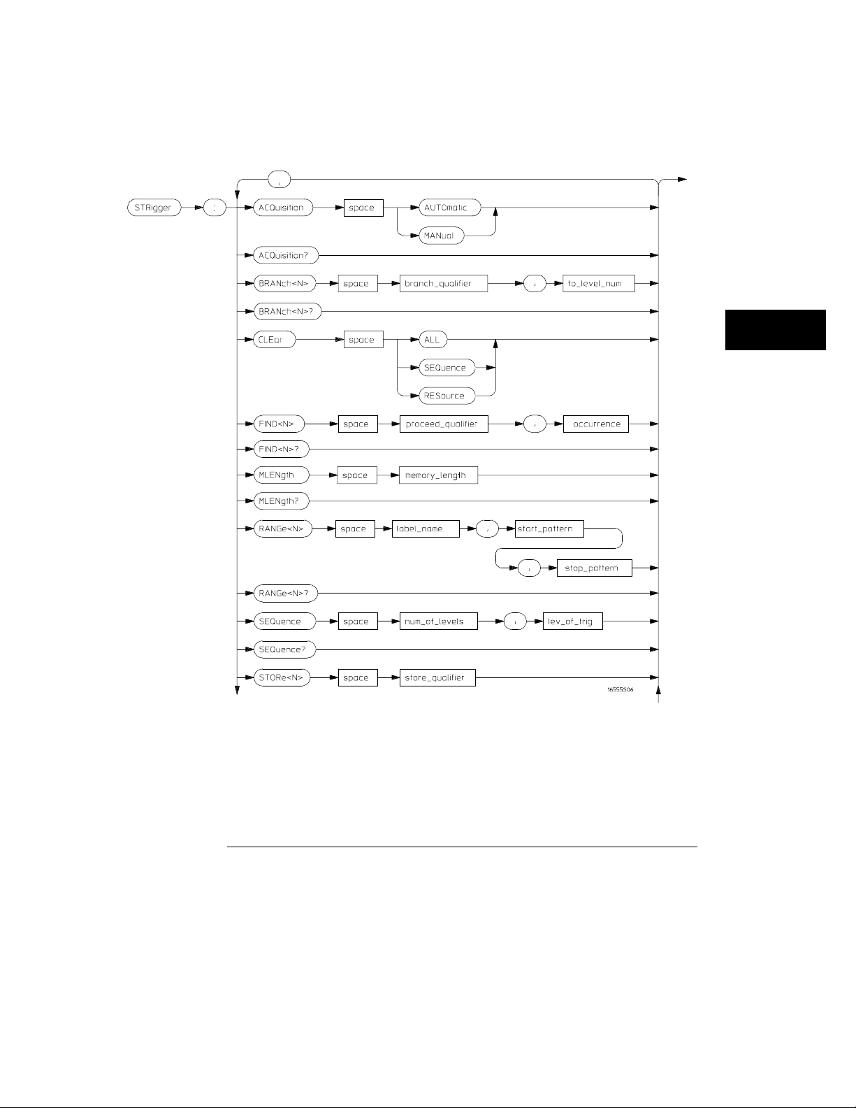
Figure 6-1
STRigger (STRace) Subsystem
STRigger Subsystem Syntax Diagram
6–3
Page 92
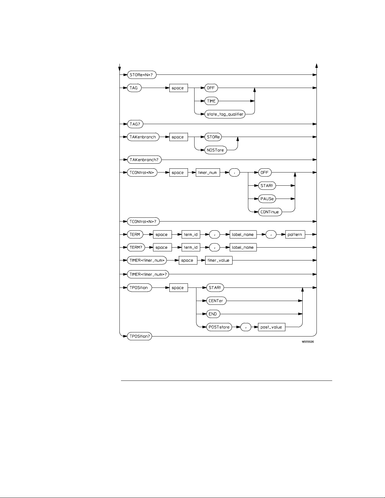
Figure 6-1 (continued)
STRigger (STRace) Subsystem
STRigger Subsystem Syntax Diagram (continued)
6–4
Page 93

Table 6-1 STRigger Subsystem Parameter Values
Parameter Value
branch_qualifier
qualifier see "Qualifier" on page 6–6
to_lev_num integer from 1 to last level
proceed_qualifier
occurrence number from 1 to 1048575
label_name string of up to 6 alphanumeric characters
start_pattern
stop_pattern
num_of_levels integer from 2 to 12
lev_of_trig integer from 1 to (number of existing sequence levels - 1)
store_qualifier
state_tag_qualifier
timer_num
timer_value 400 ns to 500 seconds
term_id
pattern
post_value integer from 0 to 100 representing percentage
memory_length
<qualifier>
<qualifier>
"{#B{0|1}...|
#Q{0|1|2|3|4|5|6|7}...|
#H{0|1|2|3|4|5|6|7|8|9|A|B|C|D|E|F}...|
{0|1|2 |3 |4 |5|6|7|8 |9}...} "
<quali fier>
<quali fier>
{1|2}
{A|B|C|D|E|F|G|H|I|J}
"{#B{0|1|X}...|
#Q{0|1|2|3|4|5|6|7|X}...|
#H{0|1|2|3|4|5|6|7|8|9|A|B|C|D|E|F|X}...|
{0|1|2|3|4|5|6|7|8|9}...}"
{4096 | 8192 | 16384 | 32768 | 65536 |
131072 | 262144 | 524288 | 1048576 |
2080768}
STRigger (STRace) Subsystem
6–5
Page 94

STRigger (STRace) Subsystem
Qualifier
Qualifier
The qualifier for the state trigger subsystem can be terms A through J, Timer
1 and 2, and Range 1 and 2. In addition, qualifiers can be the NOT boolean
function of terms, timers, and ranges. The qualifier can also be an expression
or combination of expressions as shown below and figure 6-2, "Complex
Qualifier," on page 6-10.
The following parameters show how qualifiers are specified in all commands
of the STRigger subsystem that use
<qualifier>
.
<qualifier>
<expression>
<expression1a>
<expression1a_
term>
<expression1b>
<expression1b_
term>
<expression2a>
<expression2b>
<expression2c>
<expression2d>
<expression2e>
<expression2f>
{ "ANYSTATE" | "NOSTATE" | "<expression>" }
{<expr es si on1a>|<e xpression1b>|<expression1a> OR
<expression1b>|<expression1a> AND <expression1b>}
{<expression1a_term>|(<expression1a_term>[ OR
<expression1a_term>]* )|(<expression1a_term>[ AND
<expre ss io n1a_term >]* )}
{ <expre ss io n2a>|<ex pression2b>|<expression2c>|<expression2d>}
{<expression1b_term>|( <expression1b_term>[ OR
<expression1b_term>]* )|(<expression1b_term>[ AND
<expre ss io n1b_term >]* )}
{<expr es si on2e>|<e xpression2f>|<expression2g>|<expression2h>}
{<term3a>|<term3b>|(<term3a> <boolean_op> <term3b>)}
{<term3c>|<range3a>|(<term3c> <boolean_op> <range3a>)}
{<term3d>}
{<term3e>|<timer3a>|(<term3e> <boolean_op> <timer3a>)}
{<term3f>|<term3g>|(<term3f> <boolean_op> <term3g>)}
{<term3h>|<range3b>|(<term3h> <boolean_op> <range3b>)}
<expression2g>
<expression2h>
<boolean_op>
{<term3i>}
{<term3j>|<timer3b>|(<term3j> <boolean_op> <timer3b>)}
{AND | NAND | OR | NOR | XOR | NXOR}
6–6
Page 95

STRigger (STRace) Subsystem
Qualifier
<term3a>
<term3b>
<term3c>
<term3d>
<term3e>
<term3f>
<term3g>
<term3h>
<term3i>
<term3j>
<range3a>
<range3b>
<timer3a>
<timer3b>
Qualifier Rules
{ A | NOTA }
{ B | NOTB }
{ C | NOTC }
{ D | NOTD }
{ E | NOTE }
{ F | NOTF }
{ G | NOTG }
{ H | NOTH }
{ I | NOTI }
{ J | NOTJ }
{ IN_RANGE1 | OUT_RANGE1 }
{ IN_RANGE2 | OUT_RANGE2 }
{ TIMER1 < | TI ME R1>}
{ TIMER2 < | TI ME R2>}
The following rules apply to qualifiers:
Qualifiers are quoted strings and, therefore, need quotes.
•
Expressions are evaluated from left to right.
•
Parentheses are used to change the order evaluation and are optional.
•
An expression must map into the combination logic presented in the
•
combination pop-up menu (see figure 6-2 on page 6-10).
Examples
’A’
’( A OR B )’
’(( A OR B ) AND C )’
’(( A OR B ) AND C AND IN_RANGE2 )’
’(( A OR B ) AND ( C AND IN_RANGE1 ))’
’IN_RANGE1 AND ( A OR B ) AND C’
6–7
Page 96

STRigger (STRace) Subsystem
STRigger (STRace)
STRigger (STRace)
Selector
Example
Command
Example
:MACHine{1|2}:STRigger
The STRigger (STRace) (State Trigger) selector is used as a part of a
compound header to access the settings found in the State Trace menu. It
always follows the MACHine selector because it selects a branch directly
below the MACHine level in the command tree.
OUTPUT XXX;":MACHINE1:STRIGGER:TAG TIME"
ACQuisition
:MACHine{1|2}:STRigger:ACQuisition
{AUTOmatic|MANual}
The ACQuisition command allows you to specify the acquisition mode for the
State analyzer.
OUTPUT XXX;":MACHINE1:STRIGGER:ACQUISITION AUTOMATIC"
Query
Returned Format
Example
:MACHine{1|2}:STRigger:ACQuisition?
The ACQuisition query returns the current acquisition mode.
[:MACHine{1|2}:STRigger:ACQuisition] {AUTOmatic|MANual}<NL>
OUTPUT XXX;":MACHINE1:STRIGGER:ACQUISITION?"
6–8
Page 97

BRANch
STRigger (STRace) Subsystem
BRANch
Command
:MACHine{1|2}:STRigger:BRANch<N>
<branch_qualifier>,<to_level_number>
The BRANch command defines the branch qualifier for a given sequence
level. When this branch qualifier is matched, it will cause the sequencer
to jump to the specified sequence level. The branch qualifier functions like
the "else on" branch of a sequence level.
The terms used by the branch qualifier (A through J) are defined by the
TERM command. The meaning of
determined by the RANGE command.
Within the limitations shown by the syntax definitions, complex expressions
may be formed using the AND and OR operators. Expressions are limited to
what you could manually enter through the State Trigger menu. Regarding
parentheses, the syntax definitions on the next page show only the required
ones. Additional parentheses are allowed as long as the meaning of the
expression is not changed. Figure 6-2 shows a complex expression as seen in
the State Trigger menu.
Example
OUTPUT XXX;":MACHINE1:STRIGGER:BRANCH1 ’C AND D OR F OR G’, 1"
OUTPUT XXX;":MACHINE1:STRIGGER:BRANCH1 ’((C AND D) OR (F OR G))’, 1"
OUTPUT XXX;":MACHINE1:STRIGGER:BRANCH1 ’F OR (C AND D) OR G’,1"
The following statements are all correct and have the same meaning. Notice
that the conventional rules for precedence are not followed. The expressions
are evaluated from left to right.
IN_RANGE
OUT_RANGE
and
is
<N>
<to_level_
number>
<number_of_
levels>
<branch_
qualifier>
integer from 1 to
integer from 1 to
integer from 2 to the number of existing sequence levels (maximum 12)
<qualifier>
<number_of_levels>
<number_of_levels>
see "Qualifier" on page 6-6
6–9
Page 98
STRigger (STRace) Subsystem
BRANch
Example
Query
Returned Format
Example
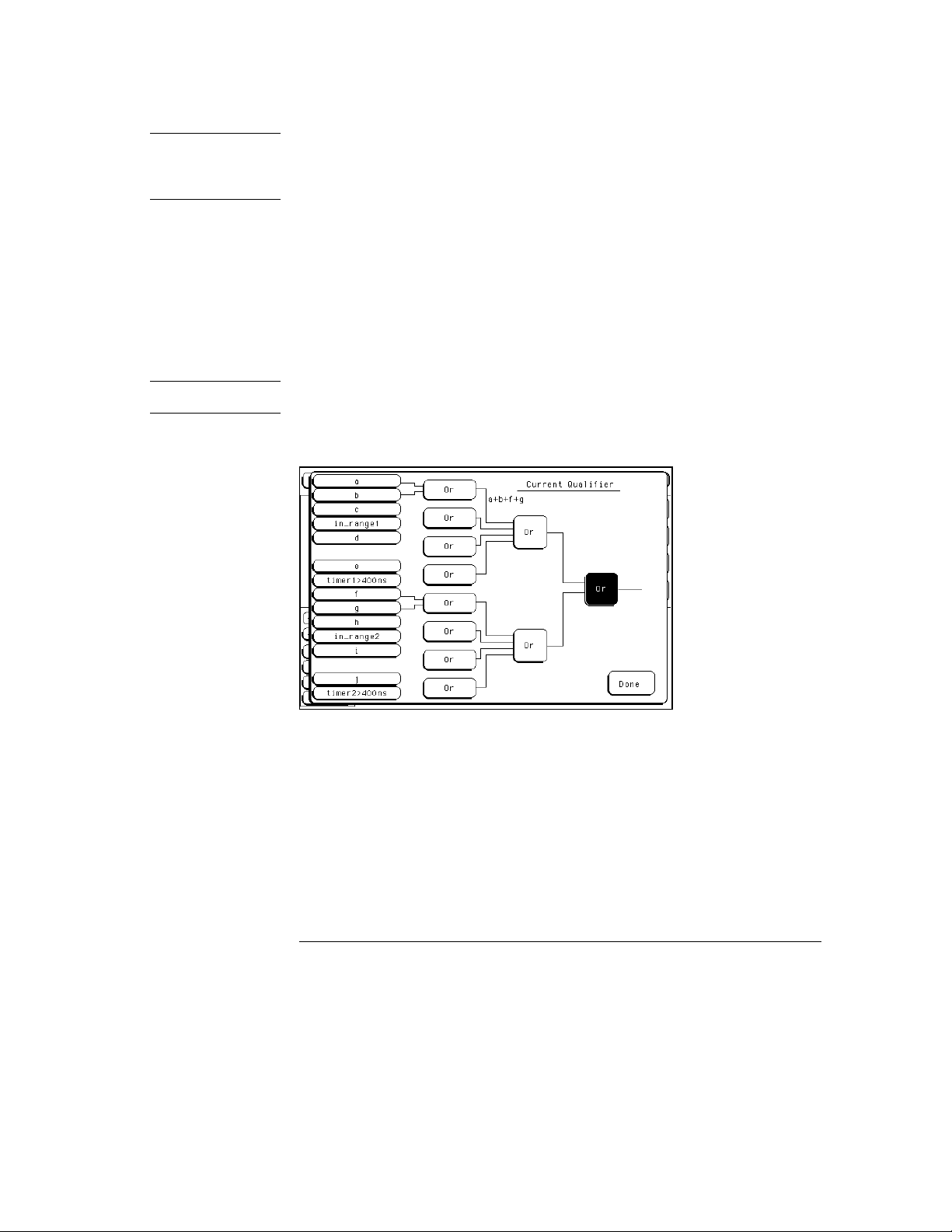
Figure 6-2
OUTPUT XXX;":MACHINE1:STRIGGER:BRANCH1 ’ANYSTATE’, 3"
OUTPUT XXX;":MACHINE1:STRIGGER:BRANCH2 ’A’, 7"
OUTPUT XXX; ":MA CHIN E1:STRIGGER:BRAN CH3 ’((A OR B) OR NOTG)’, 1"
:MACHine{1|2}:STRigger:BRANch<N>?
The BRANch query returns the current branch qualifier specification for a
given sequence level.
[:MACHine{1|2}:STRigger:BRANch <N>]
<branch_qualifier>,<to_level_n um><NL>
OUTPUT XXX;":MACHINE1:STRIGGER:BRANCH3?"
Complex qualifier
Figure 6-2 is a front panel representation of the complex qualifier
Or (f Or g)
.
6–10
(a Or b)
Page 99

STRigger (STRace) Subsystem
CLEar
Example
Command
The following example would be used to specify the complex qualifier shown
in figure 6-2.
OUTPUT XXX;":MACHINE1:STRIGGER:BRANCH1 ’((A OR B) AND (F OR
G))’, 2"
Terms A through E, RANGE 1, and TIMER 1 must be grouped together
and terms F through J, RANGE 2, and TIMER 2 must be grouped together.
In the first level, terms from one group may not be mixed with terms from the
other. For example, the expression
((A OR IN_RANGE2) AND (C OR G))
is
not allowed because the term C cannot be specified in the F, G, and I group.
In the first level, the operators you can use are
XOR, NXOR
. Either
AND
or OR may be used at the second level to join the two
AND, NAND, OR, NOR,
groups together. It is acceptable for a group to consist of a single term.
Thus, an expression like
(B AND G)
is legal, since the two operands are both
simple terms from separate groups.
CLEar
:MACHine{1|2}:STRigger:CLEar
{All|SEQuence|RESource}
Example
The CLEar command allows you to clear all settings in the State Trigger
menu, clear only the Sequence levels, or clear only the resource term
patterns. Cleared settings are replaced with the defaults.
OUTPUT XXX;":MACHINE1:STRIGGER:CLEAR RESOURCE"
6–11
Page 100

STRigger (STRace) Subsystem
FIND
FIND
Command
<occurrence>
<proceed_
qualifier>
:MACHine{1|2}:STRigger:FIND<N>
<proceed_qualifier>,<occurrence>
The FIND command defines the proceed qualifier for a given sequence level.
The qualifier tells the state analyzer when to proceed to the next sequence
level. When this proceed qualifier is matched the specified number of times,
the sequencer will proceed to the next sequence level. In the sequence level
where the trigger is specified, the FIND command specifies the trigger
qualifier (see SEQuence command).
The terms A through J are defined by the TERM command. The meaning of
IN_RANGE
Expressions are limited to what you could manually enter through the State
Trigger menu. Regarding parentheses, the syntax definitions below show
only the required ones. Additional parentheses are allowed as long as the
meaning of the expression is not changed. See page 6-9 for a detailed
example.
<N>
integer from 1 to (number of existing sequence levels −1)
integer from 1 to 1048575
<qualifier>
OUT_RANGE
and
see "Qualifier" on page 6-6
is determined by the RANGe command.
Example
OUTPUT XXX;":MACHINE1:STRIGGER:FIND1 ’ANYSTATE’, 1"
OUTPUT XXX;":MACHINE1:STRIGGER:FIND3 ’((NOTA AND NOTB) OR
G)’, 1"
6–12
 Loading...