

Page 1

Agilent 16047D Test Fixture
Operation and Service Manual
Third Edition
Agilent Technologies Japan, Ltd.
Agilent PN 16047-90300
May 2000
Printed in Japan
Page 2

Notices
The information contained in this document is subject to change without notice.
This document contains proprietary information that is protected by copyright.All
rights are reserved. No part of this document may be photocopied, reproduced, or
translated to another language without the prior written consent of the Agilent
Technologies.
Agilent Technologies Japan, Ltd.
Component Test PGU-Kobe
1-3-2, Murotani, Nishi-Ku, Kobe-shi, Hyogo, 651- 2241 Japan
Copyright © 1985, 1999, 2000 Agilent Technologies Japan, Ltd.
Manual Printing History
The manual’s printing date and part number indicate its current edition. The
printing date changes when a new edition is printed. (Minor corrections and
updates that are incorporated at reprint do not cause the date to change.) The
manual part number changes when extensive technical changes are incorporated.
November 1985 First Edition (part number : 16047-90300) August 1999 Second Edition (part number : 16047-90300) May 2000 Third Edition (part number : 16047-90300)
Safety Summary
The following general safety precautions must be observed during all phases of
operation, service, and repair of this instrument. Failure to comply with these
precautions or with sp ecific WARNINGS elsewhere in t his manual may impai r the
protection provided by the equipment. In addition it violates safety standards of
design, manufacture, and intended use of the instrument.
The Agilent T echnologies assumes no liability for the customer’s failure to comply
with these requirements.
NOTE 16047D comply with INSTALLATION CATEGORY I and POLLUTION
DEGREE 2 in IEC61010-1. 16047D are INDOOR USE product.
2
Page 3

• Ground The Instrument
To avoid electric shock hazard, the instrument chassis and cabinet must be
connected to a safety earth ground by the supplied power cable with earth
blade.
• DO NOT Operate In An Explosive Atmosphere
Do not operate the instrument in the presence of flammable gasses or fumes.
Operation of any electrical instrument in such an environment constitutes a
definite safety hazard.
• Keep Away From Live Circuits
Operating personnel must not remove instrument covers. Component
replacement and internal adjustments must be made by qualified maintenance
personnel. Do not replace component s with the power ca ble connect ed. Under
certain conditions, dangerous voltages may exist even with the power cable
removed. To avoid injuries, always disconnect power and discharge circuits
before touching them.
• DO NOT Service Or Adjust Alone
Do not attempt internal servi ce or adj ustment unles s anothe r pers on, capab le of
rendering first aid and resuscitation, is present.
• DO NOT Substitute Parts Or Modify Instrument
Because of the danger of introducing additional hazards, do not install
substitute parts or perform unauthorized modifications to the instrument.
Return the instrument to a Agilent Technologies Sales and Service Office for
service and repair to ensure that safety features are maintained.
• Dangerous Procedure Warnings
Warnings, such as the example below, precede potentially dangerous
procedures throughout this manual. Instructions contained in the warnings
must be followed.
WARNING Dangerous voltages, c apabl e of causing death, are presenting this instrument .
Use extreme caution when handling, testing, and adjusting this instrument.
Certification
Agilent Technologies certifies that this product met its published specifications at
the time of shipment from the factory. Agilent Technologies further certifies that
its calibration mea surements a re trace able to th e United S tates National I nstitut e of
Standards and Technology, to the extent allowed by the Institution’s calibration
facility, or to the calibration facilities of other International Standards
Organization members.
3
Page 4

Warranty
This Agilent Technologies instrument product is warranted against defects in
material and workmanship for a period corresponding to the individual warranty
periods of its component products. Instruments are warranted for a period of one
year. Fixtures and adapters are warranted for a period of 90 days. During the
warranty period, Agilent Technologies will, at its option, either repair or replace
products that prove to be defective.
For warranty service or repair, this product must be returned to a service facility
designated by Agilent Technologies. Buyer shall prepay shipping charges to
Agilent Technologies and Agilent Technologies shall pay shipping charges to
return the product to Buyer. However, Buyer shall pay all shipping charges,
duties, and taxes for products returned to Agilent Technologies from another
country.
Agilent Technologies warrants that its software and firmware designated by
Agilent Technologies for use with an instrument will execute its programming
instruction when pr ope rt y i nstalled on that instrument. Agilent Technologies does
not warrant that the operation of the instrument, or software, or firmware will be
uninterrupted or error free.
Limitation Of Warranty
The foregoing warranty shall not apply to defects resulting from improper or
inadequate maintenance by Buyer, Buyer-supplied software or interfacing,
unauthorized modification or misuse, operation outside the environmental
specifications for the product, or improper site preparation or maintenance.
IMPORTANT No other warranty is expressed or implied. Agilent Technologies specifically
disclaims the implied warranties of merchantability and fitness for a particular
purpose.
Exclusive Remedies
The remedies provided herein are buyer’s sole and exclusive remedies. Agilent
Technologies shall not be liable for any direct, indirect, special, incidental, or
consequential damages, whether based on contract, tort, or any other legal theory.
4
Page 5

Assistance
Product maintenance agreements and other customer assistance agreements are
available for Agilent Technologies products.
For any assistance, contact your nearest Agilent Technologies Sales and Service
Office. Addresses are provided at the back of this manual.
Safety Symbol
General definitions of safety symbols used on the instrument or in manuals are listed belo w.
Instruction Manual symbol: the product is marked with this symbol when it is
!
necessary for the user to refer to the instrument manual.
WARNING This warning sign denotes a h azard. It ca lls atte ntion to a pr ocedu re, pr actice,
condition or the like, which, if not correctly performed or adhered to, could
result in injury or death to personnel.
CAUTION This Caution sign denotes a hazard. It calls attention to a procedure, practice,
condition or the like, which, if not correctly performed or adhered to, could result
in damage to or destruction of part or all of the product.
NOTE Note denotes important information. It calls attention to a procedure, practice,
condition or the like, which is essential to highlight.
5
Page 6

6
Page 7

Contents
1. Operation
Product Description . . . . . . . . . . . . . . . . . . . . . . . . . . . . . . . . . . . . . . . . . . . . . . . 10
Specifications . . . . . . . . . . . . . . . . . . . . . . . . . . . . . . . . . . . . . . . . . . . . . . . . . . . . 11
Typical Characteristics . . . . . . . . . . . . . . . . . . . . . . . . . . . . . . . . . . . . . . . . . . . 12
Compensation for Fixture Residual Impedance Error . . . . . . . . . . . . . . . . . . . 13
2. Service
Maintenance . . . . . . . . . . . . . . . . . . . . . . . . . . . . . . . . . . . . . . . . . . . . . . . . . . . . . 16
7
Page 8

Contents
8
Page 9

1 Operation
This operation note provides the information necessary to use and service the
16047D Test Fixture. Specifications are given in Table 1-2, the test fixture is
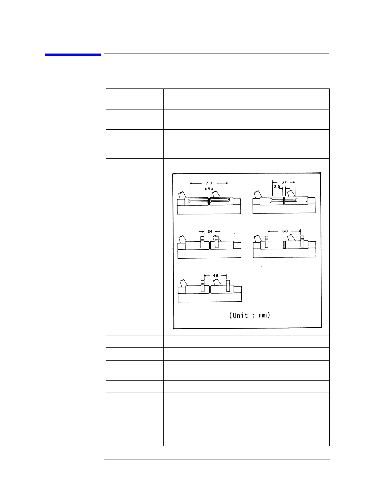
shown in Figure 1-1, and the dimensions of the contacts are shown in Table 1-2.
Table 2-1 is a list of part numbers and is used for parts identification.
9
Page 10
Operation
Product Description
Product Description
The 16047D is a direct-attachment test fixture used for the general purpose
measurement of axial and radial lead components. Three kinds of contact inserts
are furnished to simplify connections. The 16047D connects directly to the
UNKNOWN input terminals of Agilent Technologies’ s 4-te rminal pair impeda nce
measurement instruments, and converts the 4-terminal pair configuration to a
2-terminal Configuration.
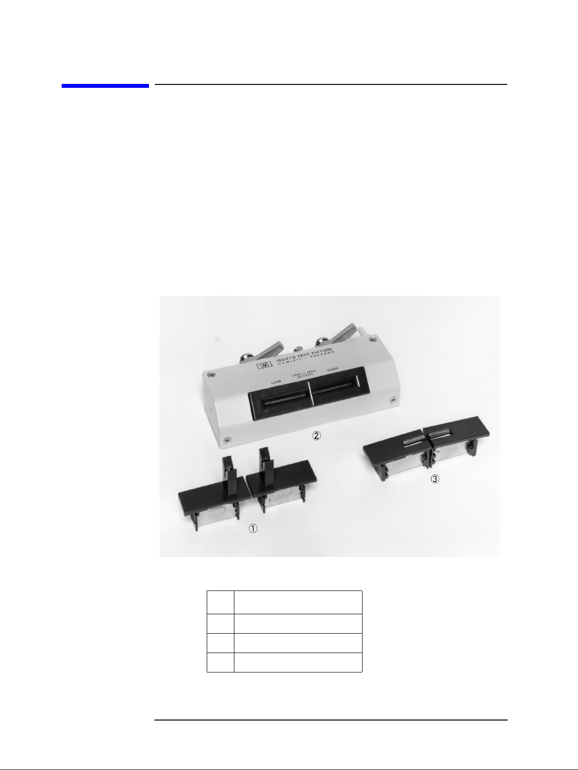
Figure 1-1 shows three contact inserts. Contact assembly (1) is used for axial lead
component measurements. For radial lead component measurements contact
assemblies (2) or (3) are us ed. These parts number is listed in Table 1-1. Ta bl e 1-2
shows the dimensions of the contact inserts. The two-pair sockets of the contact
assembly (1) can be configured three ways to match a component’s lead length.
Figure 1-1 16047D Test Fixture
Table 1-1 Part number
10 Chapter 1
Agilent Part No.
1 16061-70022 2 16061-65001 3 16047-70021
Page 11
Specifications
Table 1-2 Specifications of the 16047D
Operation
Specifications
Function:
Measurable components:
Contact Inserts:
Dimensions of Test Fixture Contacts:
For use with 4 terminal-pair LCR Meters and Impedance Analyzers.
Axial and radial lead components.
Three kinds: one for a xial l ead compo nents, o ne f or rad ial
lead components, and one for radial short lead
components.
Frequency: 100 Hz to 40 MHz Maximum Voltage:
Dimensions of test fixture:
Weight: 230 g Safety Standards: EN61010-1:1993 +A2:1995
Chapter 1 11
± 40 V
l24 (W) × 3l (D) × 62 (H) mm
IEC61010-1:1990 +A1:1992 +A2:1995
CSA C22.2 No.1010.1:1992
INSTALLATION CATEGORY I POLLUTION DEGREE 2 INDOOR USE
peak max. (AC+DC)
Page 12
Operation
f
0
2
Specifications
Typical Characteristics
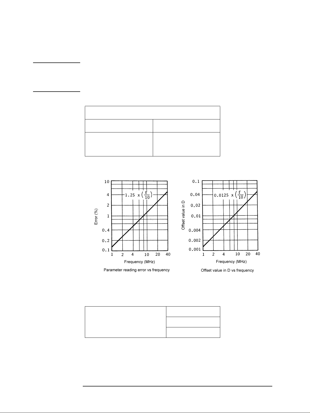
NOTE Here, f is the test frequency in MHz. The incremental errors calculated from the
equations given in this table are additive when measurements are made above l
MHz. The incremental error is applicable after completion of the Open/Short
compensation.
Table 1-3 Typical characteristics
Incremental Error at f ≥1MHz
Parameter reading error Offset Value for D
Figure 1-2
æö
1.25
----- -
×± 0.0125
èø
1
f
æö
±
×
èø
----- -
10
Table 1-4 Uncertainty of residual impedance
Frequency range: DC to 40 MHz L < 1 nH
12 Chapter 1
C < 0.1 pF
R < 0.1 Ω
Page 13

Operation
Specifications
Compensation for Fixture Residual Impedance Error
The 16047D has inherent stray capacitance, residual inductance, and residual
resistance that affect the accuracy of measured values. To compensate for, or
negate, these residuals to minimize measurement error, the instrument’s
Open/Short compensati on procedure should be perfor med. The pr oced ure is given
in the instrum ent’s operating manual.
Chapter 1 13
Page 14

Operation
Specifications
14 Chapter 1
Page 15

2 Service
15
Page 16

Service
Maintenance
Maintenance
Figure 2-1 shows an exploded view of the 16047D test fixture and a list of the
replaceable parts. Do not disassemble the unit any further than shown.
Maintenance consists principally of cleaning the contacts and replacing worn or
damaged parts. Take special care when cleaning c ontacts. Whe n ordering par ts, use
the Agilent part numbers listed in Table 2-1. If a faulty part is located in an
assembly that can not be disassembled, order the next higher assembly or return
the whole device to the nearest Agilent Technologies Sales/Service Office for
repair or replacement. Note that part numbers 25 and 26 (Contact Assy.) are
soldered assembles.
16 Chapter 2
Page 17
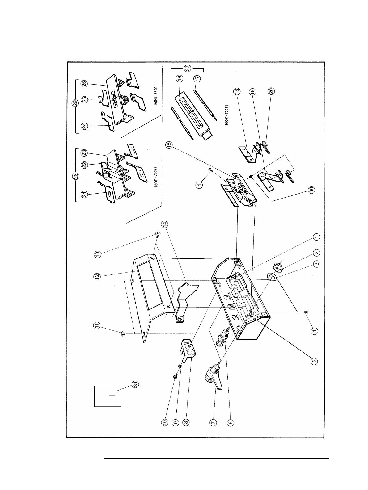
Figure 2-1 Parts Identification
Service
Maintenance
Chapter 2 17
Page 18

Service
Maintenance
Table 2-1 Replaceable Parts List
Reference Agilent Part No. Qty. Description
1 16047-04014 1 BOTTOM COVER 2 2950-0043 4 NUT 3 2190-0016 4 WASHER 4 0515-1467 4 SCREW 5 16061-50022 1 BASE 6 1250-1798 2 BNC CONNECTOR 7 16012-7122 2 BNC ASSY. 8 16047-40000 1 STOPPER 9 2190-0206 1 WASHER 10 0515-1550 1 SCREW 11 0515-0914 2 SCREW 12 16047-04012 1 TOP COVER 13 0515-0914 2 SCREW 14 16047-00619 1 SHIELD PLATE 15 16061-50024 2 SOCKET 16 16061-50031 2 SOCKET-RADIAL 17 16061-10031 4 CONTACT-RADIAL 18 16047-60003 1 CONTACT ASSY. 19 16047-60004 1 CONTACT ASSY. 20 16061-10026 2 CONTACT 21 16061-10033 2 CONTACT-AXIAL 22 16061-10032 2 CONTACT-AXIAL 23 16061-50032 2 SOCKET-AXIAL 24 16047-00604 2 CONTACT.RADIAL (SHORT) 25 16047-00605 2 CONTACT-RADIAL (SHORT) 26 16047-40001 2 SOCKET-RADIAL (SHORT) 27 16061-70021 2 RADIAL SOCKET ASSY. 28 16061-70022 2 AXIAL SOCKET ASSY.
18 Chapter 2
Page 19

Service
Maintenance
Reference Agilent Part No. Qty. Description
29 16047-65001 2 RADIAL SOCKET ASSY. (SHORT) 30 1460-2116 4 SPRING 31 5000-4226 1 SHORT BAR
Chapter 2 19
 Loading...