

Page 1

HP 37717C
Communications
Performance Analyzer
Calibration
Manual
Page 2

Copyright HewlettPackard Ltd.1998
All rights reserved.
Reproduction, adaption,
or translation without prior
written permission is
prohibited, except as
allowed under the
copyright laws.
HP Part No. 37717-90435
Second Edition, Nov 98
Printed in U.K.
Documentation
Warranty
The information contained
in this document is subject
to change without notice.
Hewlett-Packard makes no
warranty of any kind with
regard to this material,
including, but not limited
to, the implied warranties
or merchantability and
fitness for a particular
purpose.
Hewlett-Packard shall not
be liable for errors
contained herein or for
incidental or
consequential damages in
connection with the
furnishing, performance,
or use of this material.
WARNING
For details of safety, see
Safety information in this
manual.
Hewlett-Packard Limited
Telecommunications Networks Test Division
South Queensferry
West Lothian, Scotland EH30 9TG
Page 3

Calibration Manual
HP Part Number 37717-90435
Printed in U.K. November 1998
HP 37717C Communications
Performance Analyzer
Page 4

2
Page 5

Contents
1 General Information
Warranty 1-1
Responsibilities of the Customer 1-2
Certification 1-3
Assistance 1-3
Notice 1-3
Restricted Rights Legend 1-3
Instruments Covered By Manual 1-4
Storage and Shipment 1-4
Repackaging for Shipment 1-4
Weight and Dimensions 1-5
Safety Precautions for the Operator 1-6
Lifting/Carrying the HP 37717C 1-6
Using both arms to lift instrument. 1-6
Safety Symbols 1-7
Operators Maintenance 1-8
Cleaning 1-8
Cabinet Cleaning 1-8
Optical Connector Cleaning 1-8
Power Supply Fuse Replacement 1-9
Statement of Compliance 1-10
Australian EMC Regulations 1-10
Noise Declaration (German) 1-10
Electromagnetic Compatibility 1-11
Electrostatic Discharge 1-11
Specifications 1-13
Unframed PDH (Option UKK) 1-13
Structured PDH (Options UKJ, UKL) 1-14
DS1/DS3/E1/E3 structured test interfaces (Option 110) 1-17
DSn/PDH receiver 1-18
SDH MODULE: Option US1 1-19
iii
Page 6

Contents
STS-3/STM-1e and STM-0/STM-1e test and interfacing (Option 120)
(for SDH specification see A3R) 1-26
STM-1/STM-4 OPTICAL INTERFACE: Option UH2. 1-34
STM-1/STM-4 OPTICAL INTERFACE: Option URU. 1-34
STM-1/STM-4 OPTICAL INTERFACE (1310 nm) with STM-4 Overhead Option
UKT 1-35
STM-1/STM-4 (1310/1550 nm) OPTICAL INTERFACE with STM-4 Overhead
Option USN 1-36
STM-0/STM-1/STM-4 OPTICAL INTERF ACE (1310 nm) with STM-4c Overhead
Option 131 1-38
STM-0/STM-1/STM-4 OPTICAL INTERFACE (1310/1550 nm) with STM-4c
Overhead Option 130 1-40
SDH Binary Interface (Option 0YH) 1-42
MEASUREMENTS and ANALYSIS 1-54
UNFRAMED PDH (Option UKK) 1-55
SDH (Option US1) 1-57
JITTER (Options UHN, A1M, A1N, A1P, A3L, A3V and A3N) 1-62
ATM Measurement (Option UKN) 1-62
Recommended Test Equipment 1-67
2 Installation
Initial Inspection 2-1
Operating Environment 2-2
Preparation for Use 2-3
Power Requirements 2-3
Fuses 2-3
Fuse Replacement 2-3
Connecting to the Power Supply 2-4
Line Voltage Selector Switch 2-4
Power Cord 2-5
Connecting to the Network 2-6
iv
Page 7

Contents
All Connectors 2-6
Electrical Interface Connectors 2-6
Optical Interface Connectors 2-10
Laser Product Classification 2-10
Laser Warning Symbols 2-11
Swedish and Finnish Labels 2-12
Location of Laser Apertures on Options 130 and 131 2-13
Cleaning Optical Connectors 2-14
Connecting Accessories 2-15
10 Base-T Lan Connection Radiated Emissions 2-15
Hewlett-Packard Interface Bus 2-16
HP-IB Address Selection 2-17
Additional Precautions for Service Engineers 2-18
Safety Precautions 2-18
ESD Precautions 2-18
3 Performance Tests
Introduction 1
Equipment Required 1
Extra Modules Required 1
Performance Test Record 1
Calibration Cycle 1
Recall Default Settings 2
Self Test - All Options 3
Description 3
Additional Tests 4
PDH Internal Transmitter Clocks (Options UKK, [USB], UKJ,
[USA]) 6
Specifications 6
Description 6
v
Page 8

Contents
Equipment Required 6
Procedure 7
Frequency Offsets 8
PDH Transmitter Output (UKK, [USB], UKJ, [USA] 9
Specifications 9
Description 10
Equipment Required 10
Procedure 10
704 kb/s Balanced Output 11
2.048 Mb/s Balanced Output 14
8.448 Mb/s Unbalanced Output 14
Multiple PDH Transmitter Outputs (Options UHC, [US6]) 22
Specifications 22
Description 22
Equipment Required 23
Procedure 23
704 kb/s Output Pulse 23
704 kb/s Additional Outputs Delay 24
2.048 Mb/s Output Pulse 25
2.048 Mb/s Additional Output Delay 27
8.448 Mb/s Output Pulse 27
8.448 Mb/s Additional Output Delay 29
34.368 Mb/s Output Pulse 29
34.368 Mb/s Additional Outputs Delay 31
139.264 Mb/s Output Pulse 31
Additional Outputs Delay at 139.264 Mb/s 34
PDH Frame Analysis (Options UKK, [USB]) 35
Specifications 35
Equipment Required 35
Description 35
Procedure 36
Option UKK, [USB] Unstructured PDH 36
Option UKJ, [USA] Structured PDH 36
vi
Page 9

Contents
2 Mb/s Frame Analysis 37
8 Mb/s Frame Analysis 39
34 Mb/s Frame Analysis 40
140 Mb/s Frame Analysis 41
PDH Receiver Equalization (Options UKK, [USB], UKJ, [USA],
UKL, [USC], UKN, [USE]) 43
Specifications 43
Description 43
Equipment Required 43
Procedure 44
704 kb/s 44
2.048 Mb/s 45
8.448 Mb/s 46
34.368 Mb/s 46
139.264 Mb/s 46
PDH Receiver Monitor Levels (Options UKK, [USB]) 47
Specification 47
Description 47
Equipment Required 47
Procedure 47
704 kb/s 48
2.048 Mb/s 49
8.448 Mb/s 49
34.368 Mb/s 49
139.264 Mb/s 49
SPDH Receiver Monitor Levels (Options UKJ, [USA], UKL, [USC],
UKN, [USE]) 50
Specifications 50
Description 50
Equipment Required 50
Procedure 51
2.048 Mb/s 52
vii
Page 10

Contents
8.448 Mb/s 53
34.368 Mb/s 53
139.264 Mb/s 54
External 2Mb/s Mux/Demux (Options UKJ, [USA], UKN, [USA]) 55
Specifications 55
Equipment Required 56
Procedure 56
External 2Mb/s Demux (Options UKL, [USC]) 62
Specifications 62
Description 62
Equipment Required 62
Procedure 63
PDH Receiver Monitor Levels (Special Option 808) 68
Specification 68
Description 68
Procedure 68
704 kb/s 69
2.048 Mb/s 70
8.448 Mb/s 70
34.368 Mb/s 70
139.264 Mb/s 70
PDH Error Output (Options UKK, [USB]) 71
Specifications 71
Description 71
Equipment Required 71
Procedure 71
Error Output Signal 72
PDH Frequency Measurement and Looped Clock (Options UKK,
[USB], UKJ, [USA], UKL, [USC], UKN, [USE]) 73
Specifications 73
Description 73
Equipment Required 73
Procedure 73
viii
Page 11

Contents
Internal SDH Transmitter Clock (Options US1, [US5], A1T, [A1U],
A3R [A3S]) 77
Specification 77
Description 77
Equipment Required 77
Procedure 77
SDH Frequency Offsets (Options US1, [US5], A1T, [A1U], A3R
[A3S], 120) 79
Specifications 79
Description 79
Equipment Required 79
Procedure 79
External MTS Clock (Options US1, [US5], A1T, [A1U], A3R [A3S],
120) 82
Specifications 82
Description 82
Procedure 82
External MTS - 2MHz Clock 82
External MTS - 2MHz Data 83
BITS 1.5 Mb/s (Option 120 only) 83
External - MTS 64k Clock 84
STM-1 RX 84
84
STM-1 Transmitter Output Waveshape (Options US1, [US5], A1T,
[A1U], A3R [A3S], 120) 85
Specifications 85
Description 85
Procedure 85
STM-1 Receiver Monitor Input (Options US1, [US5]) 91
Specification 91
Description 91
Procedure 91
ix
Page 12

Contents
STM-1 Receiver Monitor Input (Options A1T, [A1U], A3R [A3S],
120) 93
Specification 93
Description 93
Equipment Required 93
Procedure 93
STM-1 Receiver Monitor Input (Special Option 808) 95
Specification 95
Description 95
Equipment Required 95
Procedure 95
STM-1 Receiver Input Equalization (Options US1, [US5], A1T,
[A1U], A3R [A3S], 120) 97
Specification 97
Description 97
Procedure 97
STM-1 Optical Interface (Option UH1) 98
Specification (Transmitter) 98
Specification (Receiver) 98
Description 98
Equipment Required 99
Procedure 99
STM-1/STM-4 Optical Interface (Option UH2) 101
Specification (Transmitter) 101
Specification (Receiver) 101
Description 101
Equipment Required 102
Procedure 102
STM-1/STM-4, 1550nm Optical Interface (Option URU) 104
Specification (Transmitter) 104
Specification (Receiver) 104
Description 104
Equipment Required 105
x
Page 13

Contents
Procedure 105
STM-1/STM-4 Optical Interface (Options UKT, USN) 109
Specification (Transmitter) 109
Specification (Receiver) 109
Description 109
Equipment Required 110
Procedure Option UKT and USN 111
Procedure Option USN only 113
STM-1/STM-4 Optical Interface (Options 130, 131) 117
Specification (Transmitter) 117
Specification (Receiver) 117
Description 117
Procedure Option 130 and 131 118
Procedure Option 130 only 121
Transmitted Jitter Amplitude Accuracy (Option UHK) 125
Specifications 125
Description 126
Equipment Required 126
Pre-Adjustment Setup 126
Procedure 127
Transmitted Jitter/Wander Amplitude Accuracy (Option A3K [A3Q])
132
Specifications 132
Jitter Generation: 132
Amplitude Range: 132
External Jitter: 133
Wander Generation: 133
Wander Timing Reference Input: 133
External Jitter Modulation Input: 133
Description 134
Equipment Required 135
Pre-Adjustment Setup 135
Procedure 136
xi
Page 14

Contents
Transmitted PDH Jitter Amplitude Accuracy on Range 1 136
Transmitted PDH Jitter Accuracy on Range 10 139
Transmitted SDH Jitter Accuracy on Ranges 1 & 10 141
Transmitted SDH Jitter Accuracy on Range 50 143
Transmitted PDH Jitter Accuracy on Range 80 144
External Jitter Generation 145
Wander Generation 146
Received Jitter Accuracy (Options UHN, [US9], A1M [A1Q], A1N
[A1R], A1P [A1S], A3L [A3M], A3V [A3W], A3N [A3P]) 149
Specifications 149
Overall Accuracy: See main specifications in Section 1. 149
Description 149
Equipment Required 149
Received Jitter Accuracy Procedure 150
Hit Count 151
Demodulated Jitter Output 152
W ander/Slips Measurement (Options UHN, [US9], A1M [A1Q], A1N
[A1R], A1P [A1S], A3L [A3M], A3V [A3W], A3N [A3P]) 153
Specifications 153
Timing Reference Input: 153
Wander Measurement: 153
Description 154
Equipment Required 154
Procedure 154
Jitter Receiver STM-1E Input Equalization (Options A1M [A1Q],
A1N [A1R], A1P [A1S], A3L [A3M], A3V [A3W], A3N
[A3P]) 159
Specification 159
Description 159
Equipment Required 159
Procedure 159
xii
Page 15

Contents
Jitter Receiver STM-1E Monitor Input (Options A1M [A1Q], A1N
[A1R], A1P [A1S], A3L [A3M], A3V [A3W], A3N [A3P]) 160
Specification 160
Description 160
Equipment Required 160
Procedure 160
Jitter Receiver STM-1 Optical Interface (Options A1N, [A1R], A3V
[A3W]) 162
Specification 162
Description 162
Equipment Required 162
Procedure 163
Jitter Receiver STM-1/STM-4 Optical Interface (Options A1P, [A1S],
A3N [A3P]) 165
Specification 165
Description 165
Equipment Required 165
Procedure 166
PDH Binary Interfaces (Option UH3, [US7]) 168
Specifications 168
Description 169
Procedure 169
External Clock Thresholds 169
External Clock Mark to Space Ratio 172
ETSI/ANSI Internal Transmitter Clock Rates (Option UKZ) 176
Specification 176
Description 176
DS3 Frequency Accuracy 176
E1 (2.048Mb/s) Frequency Accuracy 177
E3 (34.368Mb/s) Frequency Accuracy 177
DS1 Frequency Accuracy 178
ETSI/ANSI Transmitter Output Level and Waveshape (Option UKZ)
179
xiii
Page 16

Contents
Specifications 179
Description 179
34.368 Mb/s Positive Pulse 180
34.368 Mb/s Negative Pulse 181
2.048 Mb/s Positive Pulse 182
2.048 Mb/s Negative Pulse 184
DSX-3 Positive Pulse 185
DSX-3 Negative Pulse 186
DSX-1 Positive Pulse 187
DSX-1 Negative Pulse 188
ETSI/ANSI Receiver Equalization (Option UKZ) 190
Specifications 190
Description 190
2.048Mb/s Equalization 190
34.368 Mb/s Equalization 191
DS3 Equalization 192
DS1 Equalization 193
ETSI/ANSI Receiver Monitor Levels (Option UKZ) 194
Specifications 194
Description 194
2.048Mb/s 20dB Monitor 195
2.048Mb/s 26dB Monitor 196
2.048Mb/s 30dB Monitor 196
34.368 Mb/s 20dB Monitor 196
34.368 Mb/s 26dB Monitor 197
DS3 20dB Monitor 198
DS3 26dB Monitor 198
DS1 20dB Monitor 199
DS1 26dB Monitor 200
DS1 30dB Monitor 200
Trigger Output (Option UKZ) 201
Specification 201
Description 201
Trigger Pulse 201
xiv
Page 17

Contents
Internal SONET Transmitter Clock (Option 120) 204
Specification 204
Description 204
Equipment Required 204
Procedure 204
SONET Frequency Offsets (Option 120) 206
Specifications 206
Description 206
Equipment Required 206
Procedure 206
STS-3 Transmitter Output Waveshape (Option 120) 209
Specifications 209
Description 209
Procedure 209
STM-1/STS-3 Receiver Monitor Input (Options A1T, A1U, A3R,
[A3S], 120) 215
Specification 215
Description 215
Equipment Required 215
Procedure 215
STM-1/STS-3 Receiver Input Equalization (Options US1, [US5],
A1T, [A1U], A3R, [A3S],120) 217
Specification 217
Description 217
Procedure 217
ETSI/ANSI Internal Transmitter Clock Rates (Option 110) 218
Specification 218
Description 218
E3 (34.368Mb/s) Frequency Accuracy 218
E1 (2.048Mb/s) Frequency Accuracy 219
DS1 Frequency Accuracy 219
DS3 Frequency Accuracy 219
xv
Page 18

Contents
ETSI/ANSI Transmitter Output Level and Waveshape (Option 110)
221
Specification 221
Description 221
34.368 Mb/s Positive Pulse 222
34.368 Mb/s Negative Pulse 223
2.048 Mb/s Positive Pulse 223
2.048 Mb/s Negative Pulse 225
DSX-3 Positive Pulse 225
DSX-3 Negative Pulse 226
DSX-1 Positive Pulse 227
DSX-1 Negative Pulse 228
ETSI/ANSI Receiver Equalization (Option 110) 229
Specifications 229
Description 229
34.368 Mb/s Equalization 229
2.048Mb/s Equalization 230
DS3 Equalization 231
DS1 Equalization 232
ETSI/ANSI Receiver Monitor Levels (Option 110) 233
Specifications 233
Description 233
Equipment Required 233
Procedure 234
2.048 Mb/s 235
1.544 Mb/s (DS-1) 236
34.368 Mb/s 236
44.736 Mb/s (DS-3) 236
Performance Test Record 237
xvi
Page 19

Contents
1 Terms
ETSI / ANSI Equivalent Terms 4-1
Current / Previous Terminology 4-3
Retrofit Procedure B-4
Testing B-5
Jitter Transmitter Module Calibration B-6
Description B-6
Equipment B-6
Pre-Adjustment Setup B-6
Jitter Transmitter Calibration Procedure B-7
xvii
Page 20

Contents
xviii
Page 21

General Information
Warranty
1 General Information
Warranty
HP PRODUCT DURATION OF WARRANTY
HP 37717C 3 years
1 HP warrants HP hardware, accessories and supplies against defects in materials
and workmanship for the period specified above. If HP receives notice of such
defects during the warranty period, HP will, at its option, either repair or replace
products which prove to be defective. Replacement products may be either new
or like-new.
2 HP warrants that HP software will not fail to execute its programming
instructions, for the period specified above, due to defects in material and
workmanship when properly installed and used. If HP receives notice of such
defects during the warranty period, HP will replace software media which does
not execute its programming instructions due to such defects.
3 HP does not warrant that the operation of HP products will be uninterrupted or
error free. If HP is unable, within a reasonable time, to repair or replace any
product to a condition as warranted, customer will be entitled to a refund of the
purchase price upon prompt return of the product.
4 HP products may contain remanufactured parts equivalent to new in performance
or may have been subject to incidental use.
5 The warranty period begins on the date of delivery or on the date of installation
if installed by HP. If customer schedules or delays HP installation more than 30
days after delivery, warranty begins on the 31st day from delivery.
6 Warranty does not apply to defects resulting from (a) improper or inadequate
maintenance or calibration, (b) software, interfacing, parts or supplies not
supplied by HP , (c) unauthorized modification or misuse, (d) operation outside of
the published environmental specifications for the product, or (e) improper site
preparation or maintenance.
7 TO THE EXTENT ALLOWED BY LOCAL LAW, THE ABOVE
WARRANTIES ARE EXCLUSIVE AND NO OTHER WARRANTY OR
CONDITION, WHETHER WRITTEN OR ORAL, IS EXPRESSED OR
1-1
Page 22

General Information
Warranty
IMPLIED AND HP SPECIFICALLY DISCLAIMS ANY IMPLIED
WARRANTIES OR CONDITIONS OF MERCHANTABILITY,
SATISFACTORY QUALITY, AND FITNESS FOR A PARTICULAR
PURPOSE.
8 HP will be liable for damage to tangible property per incident up to the greater of
$300,000 or the actual amount paid for the product that is the subject of the claim,
and for damages for bodily injury or death, to the extent that all such damages are
determined by a court of competent jurisdiction to have been directly caused by
a defective HP product.
9 TO THE EXTENT ALLOWED BY LOCAL LAW, THE REMEDIES IN THIS
WARRANTY STATEMENT ARE CUSTOMER'S SOLE AND EXCLUSIVE
REMEDIES. EXCEPT AS INDICA TED ABO VE, IN NO EVENT WILL HP OR
ITS SUPPLIERS BE LIABLE FOR LOSS OF DATA OR FOR DIRECT,
SPECIAL, INCIDENTAL, CONSEQUENTIAL (INCLUDING LOST PROFIT
OR DATA), OR OTHER DAMAGE, WHETHER BASED IN CONTRACT,
TORT, OR OTHERWISE.
FOR CONSUMER TRANSACTIONS IN AUSTRALIA AND NEW ZEALAND:
THE WARRANTY TERMS CONTAINED IN THIS STATEMENT, EXCEPT TO
THE EXTENT LAWFULLY PERMITTED, DO NOT EXCLUDE, RESTRICT OR
MODIFY AND ARE IN ADDITION TO THE MANDATORY STATUTORY
RIGHTS APPLICABLE TO THE SALE OF THIS PRODUCT TO YOU.
Responsibilities of the Customer
The customer shall provide:
1 Access to the products during the specified periods of coverage to perform
maintenance.
2 Adequate working space around the products for servicing by Hewlett-Packard
personnel.
3 Access to and use of all information and facilities determined necessary by
Hewlett-Packard to service and/or maintain the products. (Insofar as these items
may contain proprietary or classified information, the customer shall assume full
responsibility for safeguarding and protection from wrongful use.)
4 Routine operator maintenance and cleaning as specified in the Hewlett-Packard
Operating and Service Manuals.
5 Consumables such as paper, disks, magnetic tapes, ribbons, inks, pens, gases,
solvents, columns, syringes, lamps, septa, needles, filters, frits, fuses, seals,
detector flow cell windows, etc.
1-2
Page 23

General Information
Warranty
Certification
Hewlett-Packard Company certifies that this product met its published specifications
at the time of shipment from the factory. Hewlett-Packard further certifies that its
calibration measurements are traceable to the United States National Bureau of
Standards, to the extent allowed by the Bureau's calibration facility and to the
calibration facilities of other International Standards Organization members!
Assistance
Product maintenance agreements and other customer assistance agreements are
available for Hewlett-Packard products.
Notice
The information contained in this document is subject to change without notice.
Hewlett-Packard shall not be liable for errors contained herein or for incidental or
consequential damages in connection with the furnishing, performance or use of this
material.
This document contains proprietary information which is protected by copyright.
All rights are reserved. No part of this document may be photocopied or reproduced
without the prior written consent of the manufacturer, Hewlett-Packard Ltd.
Restricted Rights Legend
Use, duplication, or disclosure by the government is subject to restrictions as set
forth in subdivision (b)(3)(ii) of the Rights in Technical Data and Computer
Software clause at 52.227-7013. Hewlett-Packard Company; 3000 Hanover Street;
Palo Alto, California 94304.
1-3
Page 24
General Information
Instruments Covered By Manual
Instruments Covered By Manual
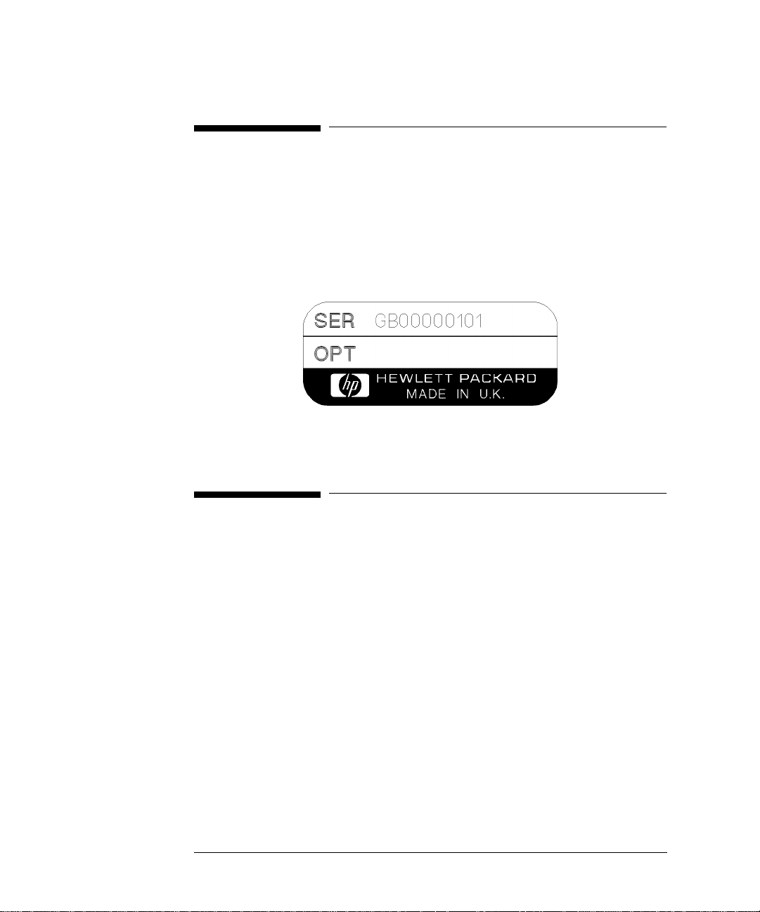
Attached to the rear panel of the instrument is a serial number plate. The serial
number plate has a two letter reference denoting country of origin (GB = Great
Britain) and an eight digit serial number. The serial number is unique to each
instrument and should be quoted in all correspondence with Hewlett-Packard,
especially when ordering replacement parts.
Serial Number Plate
Storage and Shipment
The instrument may be stored or shipped in environments within the following
limits:
Temperature -20o C to +70o C
-15o C to +50o C with lid printer
Altitude Up to 15,200 meters (50,000 feet)
The instrument should also be protected from temperature extremes which could
cause condensation within the instrument.
Repackaging for Shipment
Tagging for Service. If the instrument is being returned to Hewlett- Packard for
service, please complete a repair tag and attach it to the instrument.
1-4
Page 25

General Information
Weight and Dimensions
Original Packaging. Containers and materials identical to those used in factory
packaging are available from Hewlett-Packard offices. If the instrument is being
returned to Hewlett-Packard for servicing, attach a tag indicating the type of service
required, return address, model number, and full serial number. Mark the container
FRAGILE to ensure careful handling. In any correspondence, refer to the instrument
by model number and full serial number.
Other Packaging. The following general instructions should be followed when
repackaging with commercially available materials:
• Wrap instrument in heavy paper or plastic. If the instrument is being shipped to
Hewlett-Packard, attach a tag indicating the type of service required, return
address, model number and full serial number.
• Use a strong shipping container. A double wall carton made of 350 pound test
material is adequate.
• Use a layer of shock absorbing material 70 to 100 mm (3 to 4 inch) thick, around
all sides of the instrument to provide firm cushioning and prevent movement
inside the container. Protect the Front Panel controls and Rear Panel connectors
with cardboard.
• Seal shipping container securely.
• Mark shipping container FRAGILE to ensure careful handling.
• In any correspondence, refer to instrument by model number and full serial
number.
Weight and Dimensions
Weight: 18 kg (40 lb) fully loaded
Dimensions: 190mm (7.5in) high, 340mm (14in) wide, 420mm (17in) deep
(including cover).
1-5
Page 26

General Information
Safety Precautions for the Operator
Safety Precautions for the Operator
The following general safety precautions must be observed during all phases of
operation, service, and repair of this instrument. Failure to comply with these
precautions or with specific warnings elsewhere in this manual violates safety
standards of design, manufacture, and intended use of the instrument. HewlettPackard Company assumes no liability for the customer’s failure to comply with
these requirements.
In particular, the operator should note the following safety information:
• “Safety Symbols” on page 1-7
• “Connecting to the Power Supply” on page 2-4
• “Operating Environment” on page 2-2
• “Fuse Replacement” on page 2-3
• “Operators Maintenance” on page 1-8
• “Lifting/Carrying the HP 37717C” on page 1-6
DO NOT operate damaged equipment: Whenever it is possible that the safety
protection features built into this product have been impaired, either through
physical damage, excessive moisture, or any other reason, REMOVE POWER and
do not use the product until safe operation can be verified by service-trained
personnel. If necessary, return the product to a Hewlett-Packard Sales and Service
Office for service and repair to ensure the safety features are maintained.
Lifting/Carrying the HP 37717C
Before attempting to lift or carry the instrument consider the following basic lifting
techniques to help avoid personal injury.
Using both arms to lift instrument.
• Reach for the instrument - bend your knees and waist, and keep your back
straight.
• GRASP the instrument firmly.
• LIFT with your legs.
• KEEP your shoulders level.
1-6
Page 27

General Information
Safety Precautions for the Operator
Safety Symbols
The following symbols on the instrument and in the manual indicate precautions
which must be taken to maintain safe operation of the instrument
The Instruction Documentation Symbol. The product is marked with
this symbol when it is necessary for the user to refer to the
instructions in the supplied documentation.
Indicates the field wiring terminal that must be connected to earth
ground before operating the equipment - protects against electrical
shock in case of fault.
Frame or chassis ground terminal - typically connects to the
equipment's metal frame.
Alternating current (AC)
WARNING
CAUTION
Direct current (DC)
Indicates hazardous voltages
Warning denotes a hazard. It calls attention to a procedure, which if
not correctly performed or adhered to could result in injury or loss of
life. Do not proceed beyond a warning note until the indicated conditions are fully understood and met.
Caution denotes a hazard. It calls attention to a procedure, which if
not correctly performed or adhered to could result in damage to or
destruction of the instrument. Do not proceed beyond a warning note
until the indicated conditions are fully understood and met.
Indicates that a laser is fitted. The user must refer to the manual for
specific Warning or Caution information to avoid personal injury or
damage to the product.
1-7
Page 28

General Information
Operators Maintenance
Operators Maintenance
WARNING NO OPERATOR SERVICEABLE PARTS INSIDE. REFER SERVICING TO
QU ALIFIED PERSONNEL. TO PREVENT ELECTRICAL SHOCK DO NO T
REMOVE COVERS.
Maintenance appropriate for the operator is:
• Cabinet cleaning
• Optical Connector Cleaning
• Power supply fuse replacement
Cleaning
Cabinet Cleaning
Clean the cabinet using a dry cloth only.
Optical Connector Cleaning
It is recommended that the optical connectors be cleaned at regular intervals using
the following materials:
Description HP Part Number
Blow Brush 9300-1131
Isopropyl Alcohol 8500-5344
Lens Cleaning Paper 9300-0761
Adhesive Tape Kit 15475-68701
CAUTION Do not insert any tool or object into the IN or OUT ports of the instrument as damage
to or contamination of the optical fibre may result.
1 Recall Default settings (STORED SETTINGS 0) and remove the power from the
HP 37717C.
1-8
Page 29

General Information
Operators Maintenance
2 Remove the adapters from the IN and OUT ports.
3 Using the blow brush with the brush removed blow through the ferrule of the
standard flexible connector and the adapter.
CAUTION If the optical fibre of the fixed connector requires further cleaning this entails
disassembly of the module which should only be carried out by suitably trained
service personnel.
4 Apply some isopropyl alcohol to a piece of the cleaning paper and clean the barrel
of the adapter. Using a ne w piece of cleaning paper , clean the face of the adapter.
Repeat this operation, using a new piece of cleaning paper each time.
5 Lightly press the adhesive side of the tape provided against the front of the
adapter, then remove it quickly - repeat twice. This removes any particles of
cleaning paper which may be present.
6 Replace the adapters on the flexible connector.
Power Supply Fuse Replacement
See “Fuse Replacement” on page 2-3
1-9
Page 30

General Information
Statement of Compliance
Statement of Compliance
This instrument has been designed and tested in accordance with IEC Publication
1010-1 + A1:1992 Safety requirements for Electrical Equipment for Measurement,
Control and Laboratory Use, and has been supplied in a safe condition. The
instruction documentation contains information and warnings which must be
followed by the user to ensure safe operation and to maintain the instrument in a
safe condition.
The CE mark shows that the product complies with all relevant
European legal Directives.
This is a symbol of an Industrial Scientific and Medical Group 1
ISM 1-A
Class A product.
The CSA mark is a registered trademark of the Canadian Standards Association.
Australian EMC Regulations
The C-Tick mark is a registered trademark of the Spectrum
Management Agency of Australia. This signifies compliance with
the Australian EMC Framework Regulations under the terms of
the Radiocommunications Act of 1992.
Noise Declaration (German)
LpA<70dB
am Arbeitsplatz (operator position)
normaler Betrieb (normal position)
nach DIN 45635 pt.19 (per ISO 7779)
1-10
Page 31

General Information
Electromagnetic Compatibility
Electromagnetic Compatibility
This product has been designed to meet the protection requirements of the European
Communities Electromagnetic Compatibility (EMC) directives:
EN55011:1991 (Group 1, Class A)
EN50082-1:1992
- IEC 1000-4-2 (1995) ESD
- IEC 1000-4-3 (1995) Radiated Susceptibility
- IEC 1000-4-4 (1995) EFT
In order to preserve the EMC performance of the product, any cable which becomes
worn or damaged must be replaced with the same type and specification.
Electrostatic Discharge
When an air discharge is applied to the HP37717C in accordance with IEC 801-2
(1991), degradation in performance may be observed in the form of occasional bit
errors being counted.
See also “10 Base-T Lan Connection Radiated Emissions” on page 2-15
1-11
Page 32

General Information
Electromagnetic Compatibility
Declaration of Conformity
according to ISO/IEC Guide 22 and EN45014
Manufacturer’s Name: Hewlett-Packard Ltd.
Manufacturer’s Address:
Declares that the product
Product Name:
Model Numbers:
Product Options:
Conforms with the protection requirements of European Council Directive 89/336/EEC on the approximation
of the laws of the member states relating to electromagnetic compatibility.
Against EMC test specifications EN 55011:1991 (Group 1, Class A) and EN 50082-1:1992
As Detailed in:
Assessed by:
Technical Report Number:6893/2200/CBR, dated 21 August 1997
Supplementary Information:
The product conforms to the following safety standards:
The product herewith complies with the requirements of the Low Voltage Directive 73/23/EEC, and carries the CEmarking accordingly.
Telecomms Networks Test Division
South Queensferry
West Lothian, EH30 9TG
Scotland, United Kingdom
Communications Performance Analyzer
HP 37717C
This declaration covers all options of the above products as detailed in
TCF A-5951-9852-01
Electromagnetic Compatibility (EMC)
Technical Construction File (TCF) No. A-5951-9852-01
Dti Appointed Competent Body
EMC Test Centre,
GEC-Marconi Avionics Ltd.,
Maxwell Building,
Donibristle Industrial Park,
KY11 5LB
Scotland, United Kingdom
EN 61010-1(1993) / IEC 1010-1(1990) +A1(1992)
CSA-C22.2 No. 1010.1-92
CFR Ch.1 1040.10
EN 60825-1(1994) / IEC 825-1 (1993)
South Queensferry, Scotland 18 September 1997
Location Date W.R. Pearson / Quality Manager
1-12
Page 33

General Information
Specifications
Specifications
Except where otherwise stated, the following parameters are warranted performance
specifications. Parameters described as “typical” or “nominal” are supplemental
characteristics which provide a useful indication of typical but non-warranted
performance characteristics.
Unframed PDH (Option UKK)
Transmitter
PDH Bit rates: 704 kb/s, 2.048 Mb/s, 8.448 Mb/s, 34.368 Mb/s, 139.264Mb/s
Frequency offset: Up to ±100 ppm
Interface: Meets ITU-T G.703
Connectors: BNC 75Ω unbalanced, 3 pin Siemens 120Ω balanced
Test patterns PRBS: 215-1, 223-1 at all rates (ITU-T O.151)
Word: User-defined 16 bit word, all ones, all zeros, 1010, 1000.
Output:
704 kb/s, 2.048 Mb/s: HDB3 or AMI balanced/unbalanced.
8.448 Mb/s: HDB3 or AMI unbalanced.
34.368 Mb/s: HDB3 unbalanced.
139.264 Mb/s: CMI unbalanced.
Bit error add: 1 in 103 or single error
Clock timing Internal: All rates Recovered (loop timed): From
704 kb/s or 2.048 Mb/s receiver input.
Receiver
Input:
704 kb/s, 2.048 Mb/s: ±100 ppm, balanced/unbalanced.
8.448 Mb/s: ±100 ppm, unbalanced.
34.368 Mb/s: ±100 ppm, unbalanced.
139.264 Mb/s: ±100 ppm, unbalanced.
Line codes: As transmitter.
Autosetup: Bit rate, test pattern, framing and level of an incoming signal.
1-13
Page 34

General Information
Specifications
Jitter tolerance: To ITU-T Rec G.823.
Synchronization: Sync loss when BER
≥ 1:16 over 100 ms. Sync gain when
BER < 1:16.
Equalization: To ITU-T Rec G.703.
Monitor point compensation:
704 kb/s, 2.048 Mb/s, 8.448 Mb/s: 26
to 30 dB.
34.368, 139.264 Mb/s: 26 dB.
Frame Formats
2 Mb/s: PCM30 CAS with or without
CRC4. PCM31 with or without CRC4
8 Mb/s, 34 Mb/s, 140 Mb/s: Framed.
Structured PDH (Options UKJ, UKL)
Option UKJ provides Structured PDH
generation and measurement at
standard bit rates. Option UKL
provides measurement only at standard
bit rates.
Transmitter (Option UKJ)
Interface Bit rates: 2.048 Mb/s, 8.448
Mb/s, 34.368 Mb/s and 139.264 Mb/s.
Frequency offset: Up to ±100 ppm
Interface: Meets ITU-T G.703
Connectors: BNC 75Ω unbalanced, 3
pin Siemens 120Ω balanced
Test patterns
PRBS: 29-1, 211-1, 215-1, 223-1 at all
rates.
Word: User-defined 16 bit word, all
ones, all zeros, 1010, 1000.
Output:
2.048 Mb/s: HDB3 or AMI balanced/
unbalanced.
8.448 Mb/s: HDB3 or AMI
unbalanced.
34.368 Mb/s: HDB3 unbalanced.
139.264 Mb/s: CMI unbalanced.
1-14
Bit error add: 1 in 103, 1 in 104, 1 in
105, 1 in 106, 1 in 107or single error
Frame error add: 1 in 103, 1 in 104, 1
in 105, 1 in 106, 1 in 107or error 1 to 4
consecutive frames
Code error add: (2, 8, 34 Mb/s) 1 in
103, 1 in 104, 1 in 105, 1 in 106,1 in 10
or single error
Clock timing Internal: All rates
Recovered (loop timed): From 2.048
Mb/s receiver input.
7
Page 35

General Information
Specifications
T est signal rates: N X 64 kb/s, 64 kb/s,
2.048 Mb/s, 8.448 Mb/s, 34.368 and
139.264 Mb/s.
Frame Formats
All Rates: Unframed, Framed or
Structured.
2 Mb/s, and 64 kb/s Framing: PCM30
CAS with or without CRC4, PCM31
with or without CRC4.As ITU-T Rec.
G.704
8 Mb/s Framing: As ITU-T Rec.
G.742
34 Mb/s Framing: As ITU-T Rec.
G.751
140 Mb/s Framing: As ITU-T Rec.
G.751
Background Patterns: Unframed 29-1
PRBS, AIS or same pattern as test
signal.
External 2 Mb/s Mux I/P: Meets ITUT Rec. G.703, unbalanced HDB3 signal
only.
Receiver (Option UKJ, UKL)
Equalization at f/2: 2.048 Mb/s, 8.448
Mb/s: 6 dB34.368 Mb/s, 139.264 Mb/s:
12 dB
Monitor point compensation: 2.048
Mb/s, 8.448 Mb/s: 20 dB, 26 dB or 30
dB. 34.368, 139.264 Mb/s: 20 dB or 26
dB.
Frame Formats: As transmitter.
Frame Alignment 2 Mb/s: As ITU-T
Rec. G.706
Frame Alignment 2 Mb/s CRC4: As
ITU-T Rec. G.706.
Frame Alignment 2 Mb/s CAS: As
ITU-T Rec. G.732.
Frame Alignment 8 Mb/s: As ITU-T
Rec. G.742.
Frame Alignment 34 Mb/s: As ITU-T
Rec. G.751.
Frame Alignment 140 Mb/s: As ITUT Rec. G.751.
Frame Gain 2 Mb/s: 1 correct
sequence of FAS-NFAS-FAS.
Frame Loss 2 Mb/s: 3 consecutive
incorrect FAS or NFAS words.
Interface bit rate:
2.048 Mb/s: ±100 ppm balanced/
unbalanced.
8.448 Mb/s: ±100 ppm unbalanced.
34.368 Mb/s: ±100 ppm unbalanced.
139.264 Mb/s: ±100 ppm unbalanced.
Line codes: As transmitter.
Autosetup: Bit rate, test pattern,
framing and level of an incoming
signal.
Synchronization: Sync loss when BER
≥ 20% over 100 ms for PRBS or ≥ 4%
over100 ms for word patterns. Sync
gain when 32 consecutive error free bits
received.
Frame Gain 2 Mb/s CAS: 1 correct
CAS multiframe and the previous CAS
word is not 0000.
Frame Loss 2 Mb/s CAS: 2
consecutive errored CAS multiframe
patterns or 16 frames with CAS word
0000.
PDH Binary Interfaces (Option UH3)
Option UH3. Provides binary interfaces
for the PDH modules (Options UKK
and UKJ)
Transmitter
Binary Data Output
Data rates: 700 kb/s to 50 Mb/s (TTL),
1-15
Page 36

General Information
Specifications
700 kb/s to 170 Mb/s (ECL)
Format: NRZ
Source impedance: Nominal TTL into
75 Ω to ground or nominal ECL
into75Ω to -2V
Return loss: Typically >15 dB, 500
kHz to 100 MHz (TTL)
Binary Clock Output
Clock rates: 700 kb/s to 50 Mb/s
(TTL), 700 kb/s to 170 Mb/s (ECL)
Format: Nominal squarewa v e 60/40 to
40/60 duty cycle.
Source impedance: Nominal TTL into
75Ω to ground or nominal ECL into
75Ω to -2V
Return loss: Typically >10 dB, 500
kHz to 100 MHz (TTL)
External Clock Input
Clock rates: 700 kb/s to 50 Mb/s
(TTL), 700 kb/s to 170 Mb/s (ECL)
Logic threshold:1.5V (TTL), -1.3V
(ECL), ground (0V), signal mean level.
Termination: Nominal TTL into 75 Ω
to ground or nominal ECL into75 Ω to
-2V
Format: Nominal squarewa v e 60/40 to
40/60 duty cycle.
Return loss: Typically >15 dB, 500
kHz to 200 MHz (TTL)
Receiver
Return loss: Typically >15 dB, 500
kHz to 200 MHz (TTL)
Binary Clock Input
Clock rates: 700 kb/s to 50 Mb/s
(TTL), 700 kb/s to 170 Mb/s (ECL)
Logic threshold:1.5V (TTL), -1.3V
(ECL), ground (0V), signal mean level.
Format: Nominal squarewa v e 60/40 to
40/60 duty cycle.
Termination: Nominal TTL into 75Ω
to ground or nominal ECL into75 Ω to
-2V
Return loss: Typically >15 dB, 500
kHz to 100 MHz (TTL)
Binary interface rates: 2, 8, 34 and
140 Mb/s if Option UKJ is fitted. 0.7, 2,
8, 34and 140 Mb/s if Option UKK is
fitted.
Frequency measurement: On
external clock input and binary clock
input.
Jitter generation: Simultaneous jitter
of binary clock and binary data outputs
if Option UHK or A3K (2, 8, 34 & 140
Mb/s) is fitted.
Jitter measurement: Jitter
measurement of binary clock input if
Option UHN, A1M, A1N, A1P, A3L,
A3V or A3N (2, 8, 34 & 140 Mb/s
±100 ppm) is fitted.
Binary Data Input
Data rates: 700 kb/s to 50 Mb/s (TTL),
700 kb/s to 170 Mb/s (ECL)
Logic threshold:1.5V (TTL), -1.3V
(ECL), ground (0V).
Format: NRZ
Termination: Nominal TTL into 75Ω
to ground or nominal ECL into75Ω to 2V
1-16
Page 37

General Information
Specifications
DS1/DS3/E1/E3 structured test
interfaces (Option 110)
OUT and IN ports (used for
transmit and receive)
Type: Electrical: To ANSI T1.1021993; ITU-T O.171, G.703.
Connectors: DS1 (1.554 Mb/s):
WECO bantam, 100 Ω balanced. DS3
(44.736 Mb/s): BNC, 75 Ω,
unbalanced.E1 (2.048 Mb/s): BNC,
75 Ω, unbalanced and WECO bantam,
120 Ω balanced. E3 (34.368 Mb/s):
BNC, 75 Ω, unbalanced.
Rate: 1.544, 2.048, 34.368,
44.736 Mb/s.
DSn/PDH transmitter
Clock timing: Internal: All rates;
Recovered by the receiver.
Frequency offset generation:
Up to 100 ppm in 1 ppm steps.
Clock output: Selected transmitter
clock (internal or looped receiver
clock) used to generated DS1/DS3/E1/
E3 test output signal. (BNC connector,
externally terminated 50 Ω to ground).
Line coding: DS1: B8ZS, AMI.
DS3: B3ZS.E1: AMI, HDB3.E3:
HDB3.
Output level: DS1: DSX-1, DS1-LO.
DS3: DS3-HI, DSX-3, DS3-900'
Framing: All rates: Unframed, framed
and structured. DS1: SF (D4). DS1:
ESF to ANSI T1.403-1989, Bellcore
TR-TSY-000499 and ITU-T G.704;
the ESF data link (DL) defaults to
repetition of idle code (01111110).
DS3: M13 to ANSI T1.107-1995.
DS3: C-bit parity to ANSI T1.107a-
1990. E1: To ITU-T G.706/G.732.
E3: To ITU-T G.751.
N x 64 kb/s structured to ITU-T G.704
for E1, E3
N x 64 kb/s and N x 56 kb/s structured
for DS1 and DS3.
T est pattern:PRBS: 29-1, 211-1, 215-1,
220-1, 223-1.
QRSS (DS1 only).
3-in-24 stress pattern (DS1 only).
Word: 1010, 1000, 16 bit user word, all
ones, all zeros. The PRBS polarity of
patterns is user selectable.
Error add: DS1: Bit, FAS (Frame
Alignment Signal), BPV/code, CRC-6,
EXZ (excess zeros).
DS3: Bit, FAS, MFAS (MultiFrame
Alignment Signal), BPV/code, parity (P
bits), CP (path parity), FEBE, EXZ
(excess zeros).
E1: Bit, FAS, BPV/code, CRC-4,
REBE. E3: Bit, FAS, BPV/code.
Error insertion rate: Single. 1.0E-3.
1.1E-3. 1.0E-4 to 9.9E-9. Mantissa step
size 0.1, exponent step size 1.
Alarm generation: DS1: Loss of
signal (LOS); Out of frame (OOF);
alarm indication signal (AIS); remote
alarm indication (RAI).
DS3: LOS; LOF; AIS; RAI; far end
alarm and control (FEAC): As per
T1.107-1995.
E1: LOS, LOF, AIS, RAI.
E3: LOS, LOF, AIS, RAI.
1-17
Page 38

General Information
Specifications
FEAC code generation: With C-Bit
parity framing loopback and alarm/
status codes as per ANSI T1.107-1995
can be generated. Loopback codes: A
single burst of N loopback codes and M
messages where N and M are in the
range 1 through 15.
Alarm/status codes: Any ANSI T1.1071995 message or any
0xxxxxx011111111 message where x is
selectable may be transmitted either in
a single burst of 1 to 15 times or
continuously.
Spare bits generation: The following
spare bits can be modified;
34 Mb/s: F AS bit 12
2 Mb/s Si bits (international bits):
Timeslot 0 bit 1 in both FAS and NFAS
frames.
2 Mb/s E bits: CRC4 frames 13 and 15;
timeslot 0 bit 1.
2 Mb/s Sa bit (national bits): NFAS
timeslot bits 4 to 8.
2 Mb/s Sa bit sequences: An 8 bit
sequence may be transmitted in any
selected NFAS Sa bit when CRC4
framing has been selected. The
sequence appears in odd-numbered
CRC4 frames, starting at frame 1.
2 Mb/s CAS multiframe: MFAS
timeslot bits 5, 7 and 8.
Signaling bits generation: DS1: User
selectable Signaling ON or OFF. When
ON user selectable AB bits for SF,
ABCD for ESF and AB bits for SLC-96
framing.
Background patterns: Unframed 29-1
PRBS, AIS or same as test pattern as
foreground test signal.
Ext DS1 mux input: Weco bantam
connector, AMI or B8ZS.
Ext 2 Mb/s mux input: BNC to ITU-T
G.703, AMI or B8ZS.
DSn/PDH receiver
T ype, connectors, rates, line code and
framing: As for DSn/PDH transmitter.
Jitter tolerance: To Bellcore TR-TSY-
000009 (DS1/DS3) and ITU-T O.171.
Operating level (terminate):
User selectable as follows:
DS1 (balanced): DSX-1 to DS1-LO
levels.
DS3 (unbalanced): DS3-HI, DSX-3 and
DS3-900 levels.
E1 (balanced): 3.0 V ñ 20% for cable
lengths as per ITU-T G.703.
E1 (unbalanced): 2.37 V ñ 20% for
cable lengths as per ITU-T G.703.
E3 (unbalanced): 1.0 V ñ 20% with
automatic equalization for cable lengths
as per ITU-T G.703.
Monitor point compensation:
DS1 (balanced), E1 (balanced and
unbalanced): 20, 26 or 30 dB gain
relative to terminate mode. E1
(balanced) is restricted to half cable
length with respect to ITU-T G.703 for
26 and 30 dB gains.
DS3 and E3: 20 or 26 dB gain relative
to terminate mode.
Framing: All rates: Unframed, framed
and structured. DS1: ESF (D4).
DS1: ESF to ANSI T1.403-1989,
Bellcore TR-TSY-000499 and ITU-T
G.704; the ESF data link (DL) defaults
to repetition of idle code (01111110);
DS3: M13 to ANSI T1.107-1995.
1-18
Page 39

General Information
Specifications
DS3: C-bit parity to ANSI T1.107a-
1990. E1: To ITU-T G.706/G.732
E3: To ITU-T G.751
N x 64 kb/s structured to ITU-T G.704
for E1, E3
N x 64 kb/s and N x 56 kb/s structured
for DS1 and DS3.
SDH MODULE: Option US1
Adds SDH STM-1 electrical transmit
and receive capability, frequency offset
capability, and error and alarm
generation.
SDH Transmit and Receive
SDH rate: 155.52 Mb/s
Frequency Offset: up to ±999 ppm.
Interface: Meets ITU-T G.703.
Connector: BNC, 75 unbalanced.
Payload:
140 Mb/s: Unframed, mapped into VC-
4 according to ITU-T G.709 Figures
5.2 and 5.3.
34 Mb/s: Unframed, mapped into VC-3
according to ITU-T G.709 Figure 5.5.
Mapping route is C3-VC-3-TU-3TUG3-VC-4.
The TU-3 pointer value is 0 with
normal New Data Flag in all TU-3’s.
SS bits “10”. Background TU pointers
are the same as the foreground.
The two background VC-3’s are filled
with a fixed byte value 10101010
2 Mb/s: Unframed, mapped into VC-12
according to ITU-T G.709 Figure 5.8.
Mapping route is C12-VC-12-TU-12TUG2-TUG3-VC-4.
All background TU-12’shave mapped
29-1 PRBS payload and the same
overhead values as the foreground.
Test patterns:
PRBS: 215-1, 223-1 at all payload rates
(ITU-T O.151).
Word: User-defined 16 bit word, all
ones, all zeros, 1010, 1000.
Bit error add: 1 in 103 or single error.
Clock timing: Internal or recovered or
external MTS.
Recovered: From received SDH signal.
EXT MTS: Data or clock format as
ITU-T G.811.
TX Overhead
Regenerator section overhead:
A1A2 contains pattern F628
(hexadecimal)
C1 is set to “00000001”.
B1 is the BIP-8 parity (using even
parity) calculated over the entire
previous frame, after scrambling.
E1 is transmitted as all zeros.
F1 is transmitted as all zeros.
D1-D3 are transmitted as all zeros.
All other bytes are all zero’s.
Multiplexer section overhead:
H1,H2 - H2 and the 2 least significant
bits of H1 indicate an in-range pointer
value. The 4 most significant bits of H1
are set to 0110 indicating normal New
Data Flag. The SS bits are set to 10.
H3 is transmitted as all zeros.
B2 is the BIP-24 parity (using even
parity) calculated over the MSOH bytes
and the VC-4 capacity.
K1,K2 are transmitted as all zeros.
D4 - D12 are transmitted as all zeros.
Z1,Z2 are transmitted as all zeros.
E2 is transmitted as all zeros.
All other bytes are all zero’s.
1-19
Page 40

General Information
Specifications
User programmable
K1,K2 - Can only program 1 byte at a
time i.e. K1 or K2.
S1 - Bits 5 - 8 only.
VC-4 path overhead:
J1 - a unique ASCII message is
transmitted: “HP37717C
COMMUNICATIONS
PERFORMANCE ANALYZER,
GB00000000”. Terminated by CR,LF.
B3 is the BIP-8 parity (using even
parity) calculated over the previous
VC-4,before scrambling.
C2 is transmitted as Hexadecimal 12
(140 Mb/s Mapping) or 02 (2 Mb/s &
34 Mb/s Mapping),
G1 is transmitted as all zeros.
F2 is transmitted as all zeros.
H4 is transmitted as all zeros unless a
TU-12 payload is selected, in which
case the reduced H4 sequence defined
in ITU-T Rec. G.709 is transmitted.
Z3 - Z5 are transmitted as all zeros.
All other bytes are all zero’s.
VC-3 path overhead:
J1 - a unique ASCII message is
transmitted: “HP37717C
COMMUNICATIONS
PERFORMANCE ANALYZER,
GB00000000”. Terminated by CR,LF.
B3 is the BIP-8 parity (using even
parity) calculated over the previous
VC-3,before scrambling.
C2 is transmitted as Hexadecimal 04
(34 Mb/s mapping).
G1 is transmitted as all zeros.
F2 is transmitted as all zeros.
H4 is transmitted as all zeros.
Z3 - Z5 are transmitted as all zeros.
All other bytes are all zeros.
TU-12 overhead: V1,V2 - V2 and the
2 least significant bits of V1 are 0
indicating a pointer value of 0. The 4
most significant bits of V1 are 0110
indicating normal New Data Flag. The
SS bits are 10 indicating TU-12
payload. \
V5 - Bits 1 and 2 are the BIP-2 parity of
the previous VC-12 including V5 but
excluding V1 - V4. The VC-12 spans 4
frames.
Bits 5 - 7 are set to 010 indicating
Async mapping. All other bits are set to
0.
Pointer detection AU-4 pointer value,
TU-3 pointer value and TU-12 pointer
value.
Alarm generation
Loss of frame (LOF) STM-1 Only,
AU-4 Loss Of Pointer (AU-4 LOP),
Multiplexer Section (MS AIS),
Multiplexer Section FERF (MS FERF),
AU-4 Path AIS,
AU-4 Path FERF,
TU-3 Path AIS,
TU-3 Path FERF,
TU-3 LOP,
TU-12 Path AIS,
TU-12 Path FERF and
TU-12 LOP.
Equalization: Automatic for cable loss
up to 12 dB at half the bit rate.
Monitor point compensation: 20 dB
1-20
Page 41

General Information
Specifications
Error Generation
Error type Single Rate 10
Frame A1A2 * N in 4 frame words (STM-1 Only)
B1 * 4 - 9 STM-1 Only
B2 * 3 - 9 STM-1 Only
B3 * 4 - 9
Path FEBE * 4 - 9
VC-3 Path BIP * 3 - 9
VC-3 Path FEBE * 3 - 9
V5 BIP-2 * 3 - 9
V5 FEBE * 4 - 9
Payload Bit * 3 - 9
-N
Other
Option A3R
OUT and IN ports
(used for transmit)
Type: Electrical: To ITU-T G.703.
Connectors: BNC, 75 Ω, unbalanced.
(Small Siemens 75 Ω unbalanced
option available.)
Rate: 155.52 Mb/s. 51.84 Mb/s.
Line code: 155.52 Mb/s: CMI. 51.84
Mb/s: B3ZS.
Output level: 155.52 Mb/s: ±0.5 V
±10%. 51.84 Mb/s: Output level is user
configurable.
STM-0 X CON: 530 mV peak nominal.
STM-0 HI: 1.1 V peak nominal.
STM-0 LOW: 350m V peak
nominal.
Error output: B3 error output pulse on
receipt of STM-0 and STM-1 signals.
TTL pulse termination 75 Ω or 10 kΩ.
Simultaneous STM-1e/STM-1e
and STM-1o: When used in
conjunction with the appropriate optical
interfaces, transmit STM-1 electrical
output signal simultaneously with
optical output signal.
Transmitter
Clock timing: Internal: All rates.
Recovered: From SDH input (CMI or
NRZ electrical or optical).
Ext MTS: 64 kb/s conforming to ITU-T
G.703, 2 Mb/s conforming to ITUTG.811. BNC, 75 Ω, unbalanced or
Siemens (3-pin), 120 Ω, balanced.
(Siemens (3-pin) connector is present
on option A3R. Option 120 replaces
this connector with a Bantam
connector).
1-21
Page 42

General Information
Specifications
Frequency offset generation:
Up to ±999 ppm in 0.1 ppm steps.
Error addition:
Error type Single Rate 10
Frame A1A2 * N in 4 frame words
B1 * 4 - 9
B2 * 3 - 9
MS REI * 3 - 9
AU-4 path BIP-8 (B3) * 4 - 9
AU-4 path REI * 4 - 9
AU-4 path IEC * 4 - 9
AU-3 path BIP-8 (B3) * 4 - 9
AU-3 path REI * 4 - 9
AU-3 path IEC * 4 - 9
TU-3 path BIP-8 (B3) * 3 - 9
TU-3 path REI * 3 - 9
TU-2 path BIP (V5) * 4 - 9
TU-2 path REI * 5 - 9
TU-12 path BIP (V5) * 3 - 9
-N
Comments
TU-12 path REI * 4 - 9
TU-11 path BIP 3 - 9
TU-11 path REI 4 - 9
Bit error * * 3 - 9
† MSP threshold N errors in T ms
where 0 ≤N ≤1920 (STM-1) and 10 ms
≤T ≤10000 s, in decade steps.
1-22
* For SDH stand-alone operation, bulkfilled payloads and DS1, DS3 mapped
payloads only. For bit error rates
supported with other payloads refer to
the PDH test option for details
Page 43

General Information
Specifications
Alarm generation:
LOS, LOF, OOF, MS AIS, MS RDI,
AU-4 path AIS, AU-4 path RDI, AU-4
LOP, AU-4 path unequipped, AU-3
path AIS, AU-3 path RDI, AU-3 LOP,
AU-3 path unequipped, TU-3 path AIS,
TU-3 path RDI, TU-3 LOP, TU-3 path
unequipped, TU-2 path AIS, TU-2 path
RDI, TU-2 LOP, TU-2 path
unequipped, TU-2 H4 LOM (loss of
multiframe), TU-12 path AIS, TU-12
path RDI, TU-12 LOP, TU-12 path
unequipped, TU-12 H4 LOM (loss of
multiframe), TU-11 path AIS, TU-11
path RDI, TU-11 LOP, TU-11 path
unequipped, TU-11 H4 LOM (los of
multiframe).
Payload capability
STM-1/STM-4 payload mappings
(to ITU-T G.707):
139.264 Mb/s into a VC-4 and VC-4
bulk-filled mappings. 34.368 Mb/s into
VC-3 and VC-3 bulk-filled mappings.
2.048 Mb/s (async and fl. byte sync)
into VC-12and VC-12 bulk-filled
mappings.
DS3 (44.736 Mb/s) into VC-3 and VC3 bulk-filled mappings
DS1 (1.544 Mb/s) async into VC11†.
VC-3 - TU-3 - TUG-3 - VC-4 - AU-4 AUG; VC-3 - AU-3 - AUG.
VC-2 bulk filled mapping and TU-2-Nc
(for N = 2 to 6): VC-2 - TU-2 - TUG-2
- TUG-3 - VC-4 - AU-4 - AUG
VC-2 - TU-2 - TUG-2 - VC-3 - AU-3 AUG.
VC-12 - TU-12 - TUG-2 - TUG-3 VC-4 - AU-4. VC-12 - TU-12 - TUG-2
- TUG-3 - VC-3 - AU-3 - AUG.
VC-11 - TU-11 - TUG-2 - TUG-3 -
VC-4 - AU-4 - AUG. VC-11 - TU-11 TUG-2 - VC-3 - AU-3 - AUG
† DS1 and DS3 mappings requir e PDH
options UKJ, UKN or 110 to be fitted.
Payload data:The following unframed
patterns can be generated: (Framed and
structured signals are available in
conjunction with the PDH/DSn option
UKJ/UKN/110).
PRBS: 29-1 (O.150), 211-1 (O.152),
215-1 (O.151) and 223-1 (O.151)
QRSS (220-1, 14 zero limited)†
Word: User-defined 16-bit word, all
ones, all zeros, 1010, 1000. All PRBS
patterns can be set to inverted or noninverted.
† Applicable to DS1 mappings only.
Payload framing: 139.264, 34.368 and
2.048 Mb/s: Unframed.
139.264, 34.368 and 2.048 Mb/s:
Framed and structured.†
DS3† payloads: Unframed, C-Bit parity
(to ANSI T1.107a-1990) M13 (to ANSI
T1.107-1988).
TU-2: Unframed. DS1† payloads:
Unframed, SF (D4), ESF (to ANSI
T1.403-1989, TR-TSY-000499 and
ITU-T G.704), SLC-96.
† Only available in conjunction with
the PDH/DSn option UKJ/UKN/110.
Drop/insert: 139.264Mb/s: Drop/insert
via Tx/Rx on options UKJ/UKN.
45.736 (DS3): Drop/insert via Tx/Rx
on option 110.
34.368 Mb/s: Drop/insert via Tx/Rx on
options UKJ/UKN/110.
2.048 Mb/s: Drop/insert via drop/insert
ports on options UKJ/UKN/110.
1-23
Page 44

General Information
Specifications
1.544 Mb/s: Drop/insert via drop/insert
ports on option 110.
Pointer adjustment generation
Increment/decrement/alternating:
Provides a burst, selectable between 1
and 10 pointer adjustments (between 1
and 5 for TU-12 or TU-11 pointer).
New pointer value: The AU-4, AU-3,
TU-3, TU-2, TU-12 or TU-11 moves to
a selectable new location in a single
jump, with or without an accompanying
new data flag (NDF).
Frequency offset (and 87:3):
Pointer sequences are generated by
offsetting the frequencies of the AU-4,
AU-3 (in these modes the 87:3
sequence is generated to ITU-T G.783)
or TU-3, TU-2, TU-12, TU-11 and the
line rate relative to each other.
Range: ±100 ppm in 0.1 ppm steps.
ITU-T G.783 sequences: Bursts of
periodic single adjustments with added
or canceled adjustments. Polarity is
selectable. Bursts of periodic double
adjustments with pairs alternating in
polarity. In all cases the interval
between adjustments or pairs of
adjustments is programmable. On
starting to run any of the pointer
sequences an initialization sequence
followed by a cool down period may be
run prior to the chosen sequence.
User-defined/predefined 16-byte ITUT E.164 sequence. MSOH: K1, K2, D4
to D12, S1, M1, Z1†, Z2†, E2 (and
access to bytes reserved for national use
plus all bytes reserved for future
international standardization). VC-4
and VC-3 POH: J1, C2, G1, F2, H4, F3,
K3, N1. J1 path trace: User-defined/
predefined 16-byte ITU-T E.164
sequence or 64-byte sequence. VC-2,
VC-12, VC-11 POH: V5, J2, N2, K4.
J2 path trace: User defined/predefined
16-byte ITU-T E.164 sequence.
† Z1 and Z2 are not present in STM-0
mode.
Overhead sequence generation:
A single or multi-byte overhead
channel is overwritten with a single or
repeated sequence of programmed
values. The sequence can contain up to
five different values each being
transmitted for up to 64,000 frames.
RSOH:
6-byte channel A1A2
3-byte channel D1 to D3
Single byte channels: C1, E1, F1.
MSOH:
9-byte channel D4 to D12
2-byte channel K1K2.
Single byte channels: S1, M1, Z1†,
Z2†, E2.
† Z1 and Z2 are not present in STM-0
mode.
Transmit overhead
Overhead: Default selection: Standard
overhead values to ITU-T G.707.
SOH user-settable bytes: SOH can be
set in binary or HEX. RSOH: A1, A2,
J0, E1, F1, D1 to D3. J0 path trace:
1-24
High order POH:
Single byte channels: J1, C2, G1, F2,
H4, F3, K3, N1.
Overhead BER test: Any RSOH,
MSOH or POH (except A1, A2, H1,
H2, Z1, Z2) channel is selected and a
Page 45

General Information
Specifications
BER measurement is performed using a
29-1 PRBS inserted into a 64 kb/s
channel. Single errors can be added to
the test pattern.
MSP message generation:
Messages are displayed in text form as
per ITU-T G.783 for linear architecture
and to ITU-T G.841 for ring
architectures (MSP-ring). User
programmed sequences (K1K2).
DCC drop/insert: The data supplied to
the DCC port can be inserted into either
the regenerator section or multiplexer
section data communications channel.
Similarly, data can be dropped from
either channel. The data may be
dropped/inserted MSB or LSB first.
The data rate for access is: 192 kb/s
(RSOH DCC), 576 kb/s (MSOH DCC).
Optical interface stress test:
2 to 259 bytes of the payload are
overwritten with a block of zeros or
ones after scrambling. Alternatively the
ITU-T G.958 CID (consecutive
identical digits) test can be selected.
Tributary scan: Automatically test
BER on each SDH tributary for error
free operation. Rx setup is used to
determine tributary structure and test
pattern. Alarms: Pattern loss. T est time:
Fully user selectable. User selectable
bit error threshold: Off, > 0, ≥ 10-3,
≥ 10-6.
Mixed payloads: Backgrounds can be
individually configured to have TU-11,
TU-12 or TU-3 independently for
foreground testing channel.
Keep alive signals: PDH: T ransmit last
configured SDH signal while
transmitting a PDH signal.
SDH: With structured PDH options
transmit unframed fixed word PDH
signal while transmitting an SDH
signal.
SDH: Using unstructured PDH option
transmit last configured PDH signal
while transmitting an SDH signal.
Thru mode
T ransparent thru mode: The signal is
passed through the instrument without
being altered for monitoring purposes
where no protected monitor point is
available.
Overhead overwrite thru mode:
In addition to the above, the test
features associated with the SOH and
POH can be enabled to control one
single- or multi-byte overhead channel
(i.e. errors and alarms, optical stress
test, overhead sequences, MSP
messages, DCC insert, overhead BER.
Full Rx functionality also available).
AU-4/AU-3 overwrite thru mode:
In addition to both of the above,
overwrite the complete A U-4/A U3 with
the internally generated payload. This
enables the SOH to be looped through
while a new payload is inserted.
All of the test features which affect the
VC-4/VC-3 and/or the POH are
enabled (i.e. errors and alarms, adjust
pointer, overhead sequences, MSP
messages, overhead BER. Full Rx
functionality also available).
Tributary overwrite thru mode:
When the payload passing through the
instrument contains a TU structure, thru
mode it will be possible to choose a
1-25
Page 46

General Information
Specifications
single TU to be overwritten, as opposed
to the complete payload. All of the test
features which affect the TU and/or the
POH are enabled (i.e. errors and
alarms, adjust pointer. Full Rx
functionality also available).
STM-1e and STM-0/STM-1e
receiver functions
STM-1 receive input
Equalization: Automatic for cable loss
up to 12 dB at half the bit rate.
Monitor point compensation:
Monitor mode conforms to ITU-T
G.772. Monitor gain 20 to 26 dB.
STM-0 receive input
Operating level: Receiver mode is user
selectable.
STM-0 XCON: 530 mV peak nominal
STM-0 HI: 1.1 V peak nominal,
equalization up to 450 ft.
STM-0 LOW: 1.1 V peak nominal,
equalization from 450 to 900 ft.
Monitor point compensation:
Monitor mode conforms to ITU-T
G.772. Monitor gain 20 to 26 dB.
STS-3/STM-1e and STM-0/
STM-1e test and interfacing
(Option 120)
(for SDH specification see A3R)
OUT and IN ports (used for transmit)
Type: Electrical: To ITU-T G.703.
Connectors: BNC, 75 Ω, unbalanced.
Line code: 155.52 Mb/s: CMI.
51.84 Mb/s: B3ZS.
Output level: 155.52 Mb/s: ±0.5 V
±10%. 51.84 Mb/s: Output level is user
configurable.
STS-1 X CON: 530 mV peak nominal.
STS-1 HI: 1.1 V peak nominal.
STS-1 LOW: 350m V peak nominal.
Error output: B3 error output pulse on
receipt of STS-1 and STS-3 signals.
TTL pulse termination 75 Ω or 10 k Ω.
Simultaneous STS-3 and OC-3:
When used in conjunction with the
appropriate optical interfaces, transmit
STS-3 electrical output signal
simultaneously with OC-3 optical
output signal.
Transmitter
Clock timing: Internal: All rates.
Recovered: From SONET input (CMI
or NRZ electrical or optical)
Bits: 1.544Mb/s DS1 timing reference
as per T A-TSY-000378 Bantam, 100 Ω
nominal, unbalanced
Ext MTS: 64kb/s conforming to ITU-T
G.703, Bantam, 120 Ω balanced*
2 Mb/s conforming to ITU-T G.811,
BNC 75 Ω unbalanced,*
Bantam 120 Ω balanced.*
* Available when instrument in SDH
mode.
Frequency offset generation:
Up to ±999 ppm in 0.1 ppm steps.
Error addition:
Rate: 155.52 Mb/s. 51.84 Mb/s.
1-26
Page 47

General Information
Specifications
Error type Single Rate 10
Frame A1A2 * N in 4 frame words
CV-S (B1) * 4 - 9
CV-2 (B2) * 3 - 9
REI-L * 3 - 9
STS-3c SPE CV-P (B3) * 4 - 9
STS-3c SPE REI-P * 4 - 9
STS-3c SPE IEC-P * 4 - 9
STS-1 SPE CV-P (B3) * 4 - 9
STS-1 SPE REI-P * 4 - 9
STS-1 SPE IEC-P * 4 - 9
VT6 CV-P (V5) * 4 - 9
VT6 REI-P * 5 - 9
VT2 CV-P (V5) * 3 - 9
VT2 REI-P * 4 - 9
VT1.5 CV-P * 3 - 9
-N
Comments
VT1.5 REI-P * 4 - 9
Bit error * * 3 - 9
† APS threshold N err ors in T ms wher e
0 ≤N ≤1920 (STM-3) and 10 ms ≤T
≤10000 s, in decade steps.
* For SONET stand-alone operation,
bulk-filled payloads and DS1, DS3
mapped payloads only.
For bit error r ates supported with other
payloads refer to the DSn/PDH test
option for details.
Alarm generation: LOS, LOF, SEF,
AIS-L, RDI-L.
STS-3c SPE AIS-P, STS-3c SPE RDIP, STS-3c SPE LOP, STS-3c SPE path
unequipped.
STS-1 SPE AIS-P, STS-1 SPE RDI-P,
STS-1 SPE LOP, STS-1 SPE path
unequipped.
VT6 path AIS, VT6 RDI-V, VT6 LOP,
VT6 path unequipped, VT6 H4 LOM
(loss of multiframe).
VT2 path AIS, VT2 RDI-V, VT2 LOP,
VT2 path unequipped,
1-27
Page 48

General Information
Specifications
VT2 H4 LOM (loss of multiframe).
VT1.5 path AIS, VT1.5 RDI-V, VT1.5
LOP, VT1.5 path unequipped
VT1.5 H4 LOM (loss of multiframe).
Payload capability
Payload mappings
(to Bellcore GR-253-CORE):
OC-12/OC-12c/OC-3/OC-3c
capability when optical module fitted.
DS3(44.736 Mb/s) into STS-1 SPE and
STS-1 SPE bulk filled mappings:
DS1(1.544Mb/s) async into VT1.5.
139.264 Mb/s into a STS-3c SPE and
STS-3c SPE bulk-filled mappings.
2.048 Mb/s (async and fl. byte sync)
into VT2 SPE and VT2 SPE bulk filled
mappings:
34.368 Mb/s, into STS-1 SPE and STS1 SPE bulk filled mappings:
VT6 SPE bulk filled mapping and VT6
-Nc (for N = 2 to 6):
† DS1, DS3 mappings require DSn/
PDH option UKJ, UKN or 110 to be
fitted.
Payload data:The following unframed
patterns can be generated: (Framed and
structured signals are available in
conjunction with the PDH/DSn options
UKJ/UKN/110).
PRBS: 29-1 (O.150), 211-1 (O.152),
215-1 (O.151) and 223-1 (O.151)
QRSS (220-1, 14 zero limited)†
Word: User-defined 16-bit word, all
ones, all zeros, 1010, 1000. All PRBS
patterns can be set to be inverted or
non-inverted.
† Applicable to DS1 mappings only.
Payload framing: 139.264, 34.368 and
2.048 Mb/s: Unframed.
139.264, 34.368 and 2.048 Mb/s:
Framed and structured signals†
DS3 payloads: Unframed, C-Bit parity
(to ANSI T1.107a-1990)†
M13 (to ANSI T1.107-1988).
VT6: Unframed. DS1 payloads:
Unframed, SF (D4), ESF (to ANSI
T1.403-1989, TR-TSY-000499 and
ITU-T G.704), SLC-96†.
† Only available in conjunction with
the PDH/DSn option UKJ/UKN/110.
Drop/insert:139.264Mb/s: Drop/insert
via Tx/Rx on options UKJ/UKN.
45.736 (DS3): Drop/insert via Tx/Rx
on option 110.
34.368 Mb/s: Drop/insert via Tx/Rx on
options UKJ/UKN/110.
2.048 Mb/s: Drop/insert via drop/insert
ports on options UKJ/UKN/110.
1.544 Mb/s (DS1): Drop/insert via
drop/insert ports on option 110.
Pointer adjustment generation
Increment/decrement/alternating:
Provides a burst, selectable between 1
and 10 pointer adjustments (between 1
and 5 for VT6, VT2 and VT1.5
pointer).
New pointer value: The STS-3c SPE,
STS-1 SPE, VT6, VT2 or VT1.5 moves
to a selectable new location in a single
jump, with or without an accompanying
new data flag (NDF).
Frequency offset (and 87:3):
Pointer sequences are generated by
offsetting the frequencies of the STS-3c
SPE, STS-1 SPE (in these modes the
87:3 sequence is generated to Bellcore
GR-253-CORE/ANSI T1.105.03) or
VT6, VT2, VT1.5 and the line rate
1-28
Page 49

General Information
Specifications
relative to each other.
Range: ±100 ppm in 0.1 ppm steps.
Bellcore GR-253-CORE and
ANSI T1.105.03: Bursts of periodic
single adjustments with added or
canceled adjustments. Polarity is
selectable. Bursts of periodic double
adjustments with pairs alternating in
polarity. In all cases the interval
between adjustments or pairs of
adjustments is programmable.
On starting to run any of the pointer
sequences an initialization sequenced
followed by a cool down period may be
run prior to running the chosen
sequence.
Transmit overhead
Overhead: Default selection: Standard
overhead values to Bellcore GR-253CORE. and ANSI T1.05
STS-3/STS-1 user-settable bytes:
TOH can be set in binary or HEX.
SOH: A1, A2, J0, E1, F1, D1 to D3.
J0 path trace: User-defined/predefined
16-byte ITU-T E.164 sequence.
LOH: K1, K2, D4 to D12, S1, M1, E2
(and access to bytes reserved for
national use plus all unmarked bytes
reserved for future international
standardization).
STS-1 SPE POH: J1, C2, G1, F2, H4,
Z3, Z4,N1.
J1 path trace: User-defined/predefined
16-byte ITU-T E.164 sequence or 64byte sequence.
VT6 SPE, VT2 SPE, VT1.5 SPE POH:
V5, J2, Z6, Z7.
J2 path trace: User defined/predefined
16-byte ITU-T E.164 sequence.
Overhead sequence generation:
A single or multi-byte overhead
channel is overwritten with a single or
repeated sequence of programmed
values. The sequence can contain up to
five different values each being
transmitted for up to 64,000 frames.
SOH:
6-byte channel A1A2
3-byte channel D1 to D3
Single byte channels: C1, E1, F1.
LOH:
9-byte channel D4 to D12
2-byte channel K1K2
Single byte channels: S1,.M1, Z1†,
Z2†, E2.
† Z1 and Z2 are not present in STS-1
mode.
High order POH:
Single byte channels: J1, C2, G1, F2,
H4, Z3, Z4, N1.
Overhead BER test: Any SOH, LOH
or POH (except A1, A2, H1, H2, Z1,
Z2) channel is selected and a BER
measurement is performed using a 29-1
PRBS inserted into a 64 kb/s channel.
Single errors can be added to the test
pattern.
APS message generation: Messages
are displayed in text form as per
Bellcore GR-253-CORE for linear
architecture and to Bellcore GR-1230CORE for ring architectures (BLSR).
User programmed sequences (K1K2).
DCC drop/insert:The data supplied to
the DCC port can be inserted into either
the regenerator section or multiplexer
section data communications channel.
Similarly, data can be dropped from
1-29
Page 50

General Information
Specifications
either channel. The data may be
dropped/inserted MSB or LSB first.
The data rate for access is: 192 kb/s
(SOH DCC), 576 kb/s (LOH DCC).
Optical interface stress test:
2 to 259 bytes of the payload are
overwritten with a block of zeros or
ones after scrambling. Alternatively the
ITU-T G.958 CID (consecutive
identical digits) test can be selected.
Tributary scan: Automatically test
BER on each SONET tributary for error
free operation.
Rx setup is used to determine tributary
structure and test pattern.
Alarms: Pattern loss.
Test time: Fully user selectable.
User selectable bit error threshold: Off,
> 0, ≥10-3, ≥10-6.
Mixed payloads: Each STS-1 SPE
within an STS-3 can be independently
configured to contain a STS-1 SPE user
word, VT2 or VT1.5 structure.
Keep alive signals: DSn/PDH:
Transmit last configured SONET signal
while transmitting a DSn/PDH signal.
(i.e. errors and alarms, optical stress
test, overhead sequences, APS
messages, DCC insert, overhead BER.
Full Rx functionality also available).
STS-3c/STS-1 SPE overwrite
thru mode: In addition to both of the
above, overwrite the complete SPE
with the internally generated payload.
This enables the TOH to be looped
through while a new payload is
inserted. All of the test features which
affect the SPE and/or the POH are
enabled (i.e. errors and alarms, adjust
pointer, overhead sequences, APS
messages, overhead BER. Full Rx
functionality also available).
Tributary overwrite thru mode:
When the payload passing through the
instrument contains a VT structure, thru
mode it will be possible to choose a
single VT to be overwritten, as opposed
to the complete payload. All of the test
features which affect the VT and/or the
POH are enabled (i.e. errors and
alarms, adjust pointer. Full Rx
functionality also available).
Thru mode
Transparent thru mode:
The signal is passed through the
instrument without being altered for
monitoring purposes where no
protected monitor point is available.
Overhead overwrite thru mode:
In addition to the above, the test
features associated with the TOH and
POH can be enabled to control one
single- or multi-byte overhead channel
1-30
STS-3 and STS-1 receiver
functions
STS-3 receive input
Equalization: Automatic for cable loss
up to 12 dB at half the bit rate.
Monitor point compensation:
Monitor mode conforms to ITU-T
G.772. Monitor gain 20 to 26dB.
STS-1 receive input
Page 51

General Information
Specifications
Operating level:
Receiver mode is user selectable.
STS-1 XCON: 530 mV peak nominal.
STS-1 HI: 1.1 V peak nominal,
equalization up to 450 ft.
STS-1 LOW: 1.1 V peak nominal,
equalization from 450 to 900 ft.
Monitor point compensation:
Monitor mode conforms to ITU-T
G.772. Monitor gain 20 to 26 dB.
OVERHEAD and STRESS TEST
SDH MODULE:
Option A1T.
Adds SDH STM-1 electrical transmit
and receive capability, frequency offset
capability, error and alarm generation,
pointer sequence generation and
overhead access.
SDH Transmit and Receive
SDH rate: 155.52 Mb/s
Frequency Offset: up to 999 ppm.
Interface: Meets ITU-T G.703
Connector: BNC, 75Ω unbalanced.
Clock timing: Internal or recovered or
external MTS.
Recovered: From receiv ed SDH signal.
2.048 Mb/s (Floating byte
synchronous) mapped into VC-12
according to ITU-T G.709.
VC-2 bulk loaded and mapped into TU2 and TU-2-Nc (for N = 2-6) according
to ITU-T G.709.
Payload Data:
PRBS: 29-1, 211-1, 215-1, 223-1 (ITU-T
O.151).
W ord: User-defined 16 bit word, all
ones, all zeros, 1010, 1000.
Framed and structured payloads are
available in conjunction with the
Structured PDH option UKJ/UKN.
Payload framing: 139.264, 34.368,
and 2.048 Mb/s and TU-2 Unframed.
139.264, 34.368, and 2.048 Mb/s
framed and structured signals are
available in conjunction with the
Structured PDH option UKJ/UKN.
External payload data: 139.264 and
34.368 Mb/s data may be inserted and
dropped via the IN/OUT ports of the
Structured PDH option UKJ/UKN.
2.048 Mb/s data may be inserted and
dropped via the 2 Mb/s drop/insert
ports of the Structured PDH option
UKJ/UKN.
EXT MTS: Data or clock format as
ITU-T G.811.
Payload capability:
Payload mappings: 139.264 Mb/s
mapped into VC-4 according to ITU-T
G.709.
34.368 Mb/s mapped into VC-3
according to ITU-T G.709.
2.048 Mb/s (asynchronous) mapped
into VC-12 according to ITU-T G.709.
TX Overhead User programmable
bytes:
RSOH: A1,A2, C1, E1, F1, D1 to D3
and access to bytes reserved for
national use plus all unmarked bytes
reserved for future international
standardization.
MSOH: K1, K2, D4 to D12, S1, M1,
Z1, Z2, E2 and access to bytes reserved
for national use plus all unmarked bytes
reserved for future international
standardization.
1-31
Page 52

General Information
Specifications
VC-4 and VC-3 POH: J1, C2, G1, F2,
H4, Z3 to Z5.
J1 Path Trace: 64 byte or 16 byte, ITUT E.164 sequence or user defined byte.
VC-12 POH: J2, V5 signal label.
J2 Path Trace: 16 byte ITU-T E.164
sequence or user defined byte.
Pointer adjustment generation:
Increment/Decrement: The adjust
pointer key provides a burst selectable
between 1 and 10 pointer adjustments
(between 1 and 5 for TU-12 and TU-2
pointer).
Frequency offset: these 87:3 pointer
sequences are generated by offsetting
the frequencies of the AU-4 (or TU-3,
to each other. Range: 100 ppm in 0.1
ppm steps.
New pointer value: The AU-4, TU-3,
TU-12 or TU-2 moves to a selectable
new location in a single jump, with or
without an accompanying new data flag
(NDF).
ITU-T G.783 sequences: Bursts of
periodic single adjustments with added
or cancelled adjustments. Polarity is
selectable.
Bursts of periodic double adjustments
with pairs alternating in polarity.
In all cases the interval between
adjustments or pairs of adjustments is
programmable.
TU-12, TU-2) and the line rate relative
Error Generation
Error type Single Rate 10
-N
Other
Frame A1A2 * N in 4 frame words (STM-1 Only)
B1 * 4 - 9 STM-1 Only
B2 * 3 - 9 STM-1 Only
AU-4 Path BIP-8 * 4 - 9
MS FEBE * 3 - 9
AU-4 Path FEBE * 4 - 9
AU-4 Path IEC * 4 - 9
TU-3 Path BIP-8 * 3 - 9
TU-3 Path FEBE * 3 - 9
TU-2 Path BIP * 4 - 9
TU-2 Path FEBE * 5 - 9
TU-12 BIP * 3 - 9
1-32
Page 53

General Information
Specifications
Error Generation
Error type Single Rate 10
TU-12 FEBE * 4 - 9
Payload Bit * 3 - 9
-N
Other
Alarm generation Loss of signal
(LOS), Loss of frame (LOF) STM-1
Only, Out of frame (OOF), AU-4 Loss
Of Pointer (AU-4 LOP), AU-4 path
unequipped, AU-4 P ath AIS, AU-4 P ath
FERF, Multiplexer Section AIS (MS
AIS), Multiplexer Section FERF (MS
FERF), TU-3 Path AIS, TU-3 path
unequipped, TU-3 Path FERF,TU-3
LOP, TU-2 path AIS, TU-2 path FERF,
TU-2 LOP, TU-2 path unequipped,
TU-12 path unequipped, TU-12 Path
AIS, TU-12 Path FERF and TU-12
LOP.
Overhead sequence generation: A
single overhead channel is overwritten
with a single or repeated sequence of
programmed values. Alternatively a
BER test can be performed on a
selected byte of regenerator,
multiplexer section or path overhead.
MSP message generation: Messages
are displayed in text form as per ITU-T
G.783. Also user programmed
sequences.
DCC insert/drop: Data supplied to the
DCC port can be inserted into either the
regenerator section (192 kb/s) or
multiplexer section (576 kb/s)
communications channel. Similarly,
data can be dropped from either. Data
may be inserted/dropped MSB or LSB
first.
STM-1 optical interface stress test:
2 to 259 bytes of the payload are
overwritten with a block of zeros (or
ones for NRZ systems) after
scrambling. Alternatively the ITU-T
G.958 test can be selected.
STM-1 thru mode:
Transparent mode: The signal is
passed through the instrument
unaltered.
Overhead overwrite mode: The test
features associated with MSOH and
POH can be enabled in order to control
one single or multi byte overhead
channel.
AU-4 overwrite mode: Overwrite the
complete AU-4 with the internally
generated payload.This enables the
SOH to be looped through while a new
payload is inserted. All of the test
features which affect the VC-4 and/or
the POH are enabled.
Equalization: Automatic for cable loss
up to 12 dB at half the bit rate.
Monitor point compensation: 20 or
26 dB
Pointer detection: AU-4, TU-3 and
TU-12 pointer values.
1-33
Page 54

General Information
Specifications
STM-1 OPTICAL INTERFACE:
Option UH1.
Rate: 155.52 Mb/s
Line code: NRZ
Connectors: Adaptors to which a range
of interfaces can be attached.
Transmit:
Wavelength: 1280 - 1330 nm
Fibre power output: nominal -9 dBm
Safety classification: Class 1, FDA 21
CFR Ch.1 1040.10 and EN 60825
Receive:
Wavelength: 1200 - 1600 nm
Sensitivity: -28 dB minimum (with
1300 nm wavelength, 100% modulation
depth, BER of 10
-10
and 223 PRBS)
Maximum input power: -8 dBm (for
BER of 10
-10
)
Alarms detected: Loss of optical
signal.
STM-1/STM-4 OPTICAL INTERFACE: Option UH2.
Rate: 155.52 Mb/s, 622.08 Mb/s
Line code: NRZ
Connectors: Adaptors to which a range
of interfaces can be attached.
Transmit:
Wavelength: 1280 - 1330 nm
Fibre power output: nominal -10 dBm
Safety classification: Class 1, FDA 21
CFR Ch.1 1040.10 and EN 60825
Receive:
Wavelength: 1200 - 1600 nm
Sensitivity: -26 dB minimum (with
1300 nm wavelength, 100% modulation
depth, BER of 10
Maximum input power: -8 dBm (for
BER of 10
-10
-10
)
and 223 PRBS)
Alarms detected: Loss of optical
signal.
Background STM-1 overhead:
A1,A2 contains pattern F628
(hexadecimal)
C1 - 00000001 to 00000100
Unused C1 bytes - AA (hexadecimal)
B1 - Correct BIP-8 parity
H1,H2 - 6A and 0A (hexadecimal),
Y=93 (hexadecimal)
B2 - Correct BIP-24 parity
B3 - Correct BIP-8 parity
H4 is transmitted as all zeroes unless a
TU-12 payload is selected, in which
case the reduced H4 sequence defined
in ITU-T Rec. G.709 is transmitted.
All other overhead bytes are
transmitted as all zero’s.
STM-1/STM-4 OPTICAL INTERFACE: Option URU.
Rate: 155.52 Mb/s, 622.08 Mb/s
Line code: NRZ
Connectors: Adaptors to which a range
of interfaces can be attached.
Transmit:
Wavelength: 1520 - 1565 nm
Fibre power output: nominal -1 dBm
Safety classification: Class 1, FDA 21
CFR Ch.1 1040.10 and EN 60825
Receive:
Wavelength: 1200 - 1600 nm
Sensitivity: -26 dB minimum (with
1300 nm wavelength, 100% modulation
-10
-10
and 223 PRBS)
)
depth, BER of 10
Maximum input power: -8 dBm (for
BER of 10
Alarms detected: Loss of optical
signal.
1-34
Page 55

General Information
Specifications
Background STM-1 overhead:
A1,A2 contains pattern F628
(hexadecimal)
C1 - 00000001 to 00000100
Unused C1 bytes - AA (hexadecimal)
B1 - Correct BIP-8 parity H1,H2 - 6A
and 0A (hexadecimal), Y=93
(hexadecimal)
B2 - Correct BIP-24 parity
B3 - Correct BIP-8 parity
H4 is transmitted as all zeroes unless a
TU-12 payload is selected, in which
case the reduced H4 sequence defined
in ITU-T Rec. G.709 is transmitted.
All other overhead bytes are
transmitted as all zero’s.
Protected monitor point input:
Level: nominal 150 mV to 800 mV pk-
pk
STM-1/STM-4 OPTICAL
INTERFACE (1310 nm) with
STM-4 Overhead Option UKT
Rate: 155.52 Mb/s, 622.08 Mb/s
Line code: NRZ
Connectors: Adaptors to which a range
of interfaces can be attached.
Transmit:
Wavelength: 1280 - 1330 nm
Spectral width: 2.5 nm rms nominal
Extinction ratio: <8.2dB nominal
Fibre power output: -10dBm nominal
Safety classification: Class 3A, FDA
21 CFR Ch.1 1040.10 and EN 60825
Clock timing: Internal, recovered from
received STM-1 or STM-4 optical
signal, recovered from receiv ed STM-1
electrical signal, external MTS - data or
clock format (as ITU-T G.811)
Frequency offset generation: Up to
±999 ppm in 0.1 ppm steps
STM-4 error add (Not available if
SDH option is US1): Frame - single
and N in 4 frame words, MS B2 BIP 10-4 to 10
STM-4 alarm generation: Loss of
signal (requires A1T), loss of frame
(requires A1T), multiplexer section
AIS, multiplexer section FERF.
STM-4 thru mode: The STM-4 signal
is passed through the HP 37717C
without being altered for monitoring
purposes where no protected monitor
point is available.
STM-4 Tx Overhead: Standard
overhead values to ITU-T G.70X
User programmable bytes (Not
available if SDH option is US1):
RSOH: A1, A2, C1, E1, F1, D1-D3
MSOH: H1 (SS bits only), K1, K2,
D4-D12, S1, Z2 (column 4), Z1 & Z2
(for STM-1 under test),M1 (when
STM-1 number 3 selected for test)
STM-4 sequence generation (Not
available if SDH option is US1): A
single or multi-byte overhead channel
is overwritten with a single or repeating
sequence of programmed values. The
sequence can contain up to 5 different
values each being transmitted for up to
64,000 frames.
RSOH: D1-D3, E1, F1, C1 (for STM-1
under test), D4-D12, K1-K2, S1, E2,
Z1 & Z2 (for STM-1under test), M1
(when STM-1 number 3 selected for
test)
High order POH: J1, C2, G1, F2, H4,
Z3, Z4, Z5 (for STM-1 under test)
STM-4 overhead BER test (Not
available if SDH option is US1): Any
-9
1-35
Page 56

General Information
Specifications
overhead channel listed under STM-4
sequence generation (except Z1, Z2)
can have a 29-1 PRBS inserted into a 64
kb/s channel. Single errors can be
added to the test pattern and a BER
measurement performed.
STM-4 MSP message generation:
Messages are displayed in text form as
ITU-T G.783.
User programmed sequences (Not
available if SDH option is US1).
Receive:
Wavelength: 1200 - 1600 nm
Sensitivity: STM-1 -34dBm
minimum, STM-4 -28 dB minimum
(with 1300 nm wavelength,100%
modulation depth, BER of 10
223 PRBS)
Maximum input power: -8 dBm (for
BER of 10
Protected monitor point:
Input level: nominal 150 mV to 1000
mV pk-pk
Line code: NRZ
Impedance: Nominal 50Ω, AC
coupled
Optical power measurement: Range 0
to -30dBm, Accuracy ±1dB
STM-4 error results: RS B1, MS B2
STM-4 alarms detected: Loss of
signal, loss of frame, out of frame,
multiplexer section AIS, multiplexer
section FERF, clock loss, K1/K2
change, (Not available if SDH option is
US1).
STM-4 overhead sequence capture:
A single or multibyte overhead channel
can be monitored. After a manual or
programmed trigger, the captured byte
values are displayed together with the
number of consecutive frames
containing the value.
-10
). Damage level +10 dBm
-10
and
RSOH: A1A2, E1, F1, C1, (for STM-1
under test), D1-D3
MSOH: H1H2, K1K2, D4-D12, S1,
E2, Z1 & Z2 (for STM-1 under test),
M1 (when STM-1 number3 selected for
test)
High order POH: J1, C2, G1, F2, H4,
Z3, Z4, Z5 (for STM-1 under test)
STM-4 overhead BER measurement
(Not available if SDH option is US1):
Any RSOH, MSOH or POH channel
listed under STM-4 overhead sequence
capture can be selected and a BER
measurement using the 29-1 PRBS
provided by the transmit overhead BER
test function. Error count, error ratio,
error free seconds, percentage error free
seconds and pattern loss seconds are
calculated
STM-1/STM-4 (1310/1550 nm)
OPTICAL INTERFACE with
STM-4 Overhead Option USN
Rate: 155.52 Mb/s, 622.08 Mb/s
Line code: NRZ
Connectors: Adaptors to which a range
of interfaces can be attached.
Transmit:
Wavelength: 1280 - 1330 nm or 1520 -
1565 nm
Spectral width: 2.5 nm rms nominal
Extinction ratio: 1310 nm - <8.2dB
nominal, 1550 nm - <10dB nominal
Fibre power output: 1310 nm -10dBm
nominal 1550 nm -1 dBm nominal
Safety classification: Class 3A, FDA
21 CFR Ch.1 1040.10 and EN 60825
Clock timing: Internal, recovered from
received STM-1 or STM-4 optical
signal, recovered from receiv ed STM-1
1-36
Page 57

General Information
Specifications
electrical signal, external MTS - data or
clock format (as ITU-T G.811)
Frequency offset generation: Up to
±999 ppm in 0.1 ppm steps
STM-4 error add (Not available if
SDH option is US1): Frame - single
and N in 4 frame words, MS B2 BIP 10-4 to 10
-9
STM-4 alarm generation: Loss of
signal (requires A1T), loss of frame
(requires A1T), multiplexer section
AIS, multiplexer section FERF.
STM-4 thru mode: The STM-4 signal
is passed through the HP 37717C
without being altered for monitoring
purposes where no protected monitor
point is available.
STM-4 Tx Overhead: Standard
overhead values to ITU-T G.70X
User programmable bytes (Not
available if SDH option is US1):
RSOH:A1, A2, C1, E1, F1, D1-D3
MSOH: H1 (SS bits only), K1, K2,
D4-D12, S1, Z2 (column 4), Z1 & Z2
(for STM-1 under test), M1 (when
STM-1 number 3 selected for test)
STM-4 sequence generation (Not
available if SDH option is US1): A
single or multi-byte overhead channel
is overwritten with a single or repeating
sequence of programmed values. The
sequence can contain up to 5 different
values each being transmitted for up to
64,000 frames.
RSOH: D1-D3, E1, F1, C1 (for STM-1
under test), D4-D12, K1-K2, S1, E2,
Z1 & Z2 (for STM-1under test), M1
(when STM-1 number 3 selected for
test)
High order POH: J1, C2, G1, F2, H4,
Z3, Z4, Z5 (for STM-1 under test)
STM-4 overhead BER test (Not
available if SDH option is US1): Any
overhead channel listed under STM-4
sequence generation (except Z1, Z2)
can have a 29-1 PRBS inserted into a 64
kb/s channel. Single errors can be
added to the test pattern and a BER
measurement performed.
STM-4 MSP message generation:
Messages are displayed in text form as
ITU-T G.783.
User programmed sequences (Not
available if SDH option is US1).
Receive:
Wavelength: 1200 - 1600 nm
Sensitivity: STM-1 -34dBm
minimum, STM-4 -28 dB minimum
(with 1310 nm wavelength,100%
modulation depth, BER of 10
-10
and
223 PRBS)
Maximum input power: -8 dBm (for
BER of 10
-10
). Damage level +10 dBm
Protected monitor point:
Input level: nominal 150 mV to 1000
mV pk-pk
Line code: NRZ
Impedance: Nominal 50Ω, AC
coupled
Optical power measurement: Range 0
to -30dBm, Accuracy ±1dB
STM-4 error results: RS B1 BIP, MS
B2 BIP
STM-4 alarms detected: Loss of
signal, loss of frame, out of frame,
multiplexer section AIS, multiplexer
section FERF, clock loss, K1/K2
change, (Not available if SDH option is
US1).
STM-4 overhead sequence capture
1-37
Page 58

General Information
Specifications
(Not available if SDH option is US1):
A single or multibyte overhead channel
can be monitored. After a manual or
programmed trigger, the captured byte
values are displayed together with the
number of consecutive frames
containing the value.
RSOH: A1A2, E1, F1, C1, (for STM-1
under test), D1-D3
MSOH: H1H2, K1K2, D4-D12, S1,
E2, Z1 & Z2 (for STM-1 under test),
M1 (when STM-1 number3 selected for
test)
High order POH: J1, C2, G1, F2, H4,
Z3, Z4, Z5 (for STM-1 under test)
STM-4 overhead BER measurement
(Not available if SDH option is US1):
Any RSOH, MSOH or POH channel
listed under STM-4 overhead sequence
capture can be selected and a BER
measurement performed using the 29-1
PRBS provided by the transmit
overhead BER test function.
Error count, error ratio, error free
seconds, percentage error free seconds
and pattern loss seconds are calculated.
STM-0/STM-1/STM-4
OPTICAL INTERF ACE (1310
nm) with STM-4c Overhead
Option 131
Rate: 51.84 Mb/s, 155.52 Mb/s
Line code: NRZ
Connectors: Adaptors to which a range
of interfaces can be attached.
Transmit:
Wavelength: 1280 - 1330 nm
Spectral width: 2.5 nm rms nominal
Extinction ratio: <8.2dB nominal
Fibre power output: -10dBm nominal
Safety classification: Class 3A, FDA
21 CFR Ch.1 1040.10 and EN 60825
Clock timing: Internal, recovered from
received STM-0, STM-1 or STM-4
optical, electrical or binary signal,
external MTS - data or clock format (as
ITU-T G.811)
Frequency offset generation: Up to
±999 ppm in 0.1 ppm steps
VC-4-4C error add: B3 BIP, HP REI,
HP IEC - 10-4 to 10-9, Bit - 10-3 to 10-9.
VC-4-4C alarm generation: AU-AIS,
HP-RDI, AU-LOP, Path Unequipped
STM-4 error add: Frame - single and
N in 4 frame words, B1 BIP - 10-4 to
10-9, B2 BIP and RS REI - 10-3 to 10
STM-4 alarm generation: Loss of
signal, loss of frame, out of frame,
multiplexer section AIS, multiplexer
section RDI.
STM-4 thru mode:
Transparent mode: The STM-4
signal is passed through the HP 37717B
without being altered. The BIP’s are not
recalculated.
Overhead overwrite STM-4 mode:
The test features associated with the
section overhead can be enabled in
order to control one single or multi byte
overhead channel. The B1 and B2 bytes
are recalculated.
Overhead overwrite STM-4-4C
mode: The test features associated with
the section overhead and path overhead
can be enabled in order to control one
single or multi byte overhead channel.
The B1, B2 and B3 bytes are
recalculated.
AU-4 overwrite mode: Overwrite the
complete AU-4 with the internally
generated payload. This enables the
-9,
1-38
Page 59

General Information
Specifications
SOH and the three background AU-4’s
to be looped through while a new
payload is inserted into the STM-1
under test. All of the test features which
affect the VC-4 and/or the POH are
enabled. The B1, B2 and B3 bytes are
recalculated. The AU-4 under test is
delayed by a greater amount than the
three background AU-4’s.
Tributary overwrite: If the payload
contains a TU structure a single TU can
be overwritten. All of the test features
which affect the tributary and/or the
POH are enabled. The B1, B2, B3 and
TU BIP bytes are recalculated.
STM-4 Tx Overhead: Standard
overhead values to ITU-T G.707
User programmable bytes:
RSOH: A1, A2, J0, Z0, E1, F1, D1-D3
MSOH: H1 (SS bits only), K1, K2,
D4-D12, S1, Z1 & Z2, M1.
STM-4 sequence generation: A single
or multi-byte overhead channel is
overwritten with a single or repeating
sequence of programmed values. The
sequence can contain up to 5 different
values each being transmitted for up to
64,000 frames.
RSOH: D1-D3, J0, E1, F1, Z0.
MSOH: D4-D12, K1-K2, S1, E2, M1,
Z1, Z2.
High order POH: J1, C2, G1, F2, H4,
F3, K3, N1 (for STM-1 under test)
STM-4 overhead BER test: Any
overhead channel listed under STM-4
sequence generation (except Z1, Z2)
can have a 29-1 PRBS inserted into a 64
kb/s channel. Single errors can be
added to the test pattern and a BER
measurement performed.
STM-4 MSP message generation:
Messages are displayed in text form as
ITU-T G.783 (Linear) or ITU-T G.841
(Ring).
Receive:
Wavelength: 1200 - 1600 nm
Sensitivity: STM-0 and STM-1 -
34dBm minimum, STM-4 -28 dB
minimum (with 1300 nm
wavelength,100% modulation depth,
BER of 10
-10
and 223 PRBS)
Maximum input power: -8 dBm (for
BER of 10
-10
). Damage level +10 dBm
Protected monitor point:
Input level: nominal 150 mV to 1000
mV pk-pk
Line code: NRZ
Impedance: Nominal 50Ω, AC
coupled
Optical power measurement: Range 0
to -30dBm, Accuracy ±1dB
STM-4 error results: Frame (A1A2),
B1 BIP, B2 BIP, MS REI
VC-4--4c error results: B3 BIP, HP
REI, HP IEC, Bit
STM-4 alarms detected: Loss of
signal, loss of frame, out of frame, MS
AIS, MS RDI, K1/K2 change.
STM-4c alarms detected: All STM-4
alarms and Loss of pointer, AU AIS,
HP RDI, pattern sync loss
STM-4 overhead sequence capture:
A single or multibyte overhead channel
can be monitored. After a manual or
programmed trigger, the captured byte
values are displayed together with the
number of consecutive frames
containing the value.
RSOH: A1A2 for all four STM-1’s, J0
E1, F1, D1-D3, ZO.
MSOH: H1H2, K1K2, D4-D12, S1,
E2, Z1, Z2
1-39
Page 60

General Information
Specifications
High order POH: J1, C2, G1, F2, H4,
F3, K3, N1 for STM-1 under test)
Overhead BER measurement (STM-
4): J0, Z0, E1, F1, D1, D2, D3, D4, D5,
D6, D7, D8, D9, D10, D11, D12, K1,
K2, S1, M1, E2, J1, C2, G1, F2, H4,
F3, K3 & N1. A BER measurement can
be performed on any of these bytes
using the 29-1 PRBS provided by the
transmit overhead BER test function.
Error count, error ratio, error free
seconds, percentage error free seconds
and pattern loss seconds are calculated
STM-0/STM-1/STM-4
OPTICAL INTERFACE
(1310/1550 nm) with STM-4c
Overhead Option 130
Rate: 51.84 Mb/s, 155.52 Mb/s, 622.08
Mb/s
Line code: NRZ
Connectors: Adaptors to which a range
of interfaces can be attached.
Transmit:
Wavelength: 1280 - 1330 nm and 1520
- 1565 nm.
Spectral width (3dB): 2.5 nm rms
nominal (1310 nm)
Spectral width (20dB): 1 nm rms
nominal (1550 nm)
Extinction ratio: <8.2dB nominal
(1310 nm), <10 dBm nominal (1550
nm).
Fibre power output: -10dBm nominal
(1310 nm), -1 dBm nominal (1550 nm).
Safety classification: Class 3A, FDA
21 CFR Ch.1 1040.10 and EN 60825
Clock timing: Internal, recovered from
received STM-0, STM-1 or STM-4
optical, electrical or binary signal,
external MTS - data or clock format (as
ITU-T G.811)
Frequency offset generation: Up to
±999 ppm in 0.1 ppm steps
VC-4-4C error add: B3 BIP, HP REI,
HP IEC - 10-4 to 10-9, Bit - 10-3 to 10-9.
VC-4-4C alarm generation: AU-AIS,
HP-RDI, AU-LOP, Path Unequipped
STM-4 error add: Frame - single and
N in 4 frame words, B1 BIP - 10-4 to
10-9, B2 BIP and RS REI - 10-3 to 10
STM-4 alarm generation: Loss of
signal, loss of frame, out of frame,
multiplexer section AIS, multiplexer
section RDI.
STM-4 thru mode:
Transparent mode: The STM-4
signal is passed through the HP 37717B
without being altered. The BIP’s are not
recalculated.
Overhead overwrite STM-4 mode:
The test features associated with the
section overhead can be enabled in
order to control one single or multi byte
overhead channel. The B1 and B2 bytes
are recalculated.
Overhead overwrite STM-4-4C
mode: The test features associated with
the section overhead and path overhead
can be enabled in order to control one
single or multi byte overhead channel.
The B1, B2 and B3 bytes are
recalculated.
AU-4 overwrite mode: Overwrite the
complete AU-4 with the internally
generated payload. This enables the
SOH and the three background AU-4’s
to be looped through while a new
payload is inserted into the STM-1
under test. All of the test features which
affect the VC-4 and/or the POH are
-9,
1-40
Page 61

General Information
Specifications
enabled. The B1, B2 and B3 bytes are
recalculated. The AU-4 under test is
delayed by a greater amount than the
three background AU-4’s.
Tributary overwrite: If the payload
contains a TU structure a single TU can
be overwritten. All of the test features
which affect the tributary and/or the
POH are enabled. The B1, B2, B3 and
TU BIP bytes are recalculated.
STM-4 Tx Overhead: Standard
overhead values to ITU-T G.707
User programmable bytes:
RSOH: A1, A2, J0, Z0, E1, F1, D1-D3
MSOH: H1 (SS bits only), K1, K2,
D4-D12, S1, Z1 & Z2, M1.
STM-4 sequence generation: A single
or multi-byte overhead channel is
overwritten with a single or repeating
sequence of programmed values. The
sequence can contain up to 5 different
values each being transmitted for up to
64,000 frames.
RSOH: D1-D3, J0, E1, F1, Z0.
MSOH: D4-D12, K1-K2, S1, E2, M1,
Z1, Z2.
High order POH: J1, C2, G1, F2, H4,
F3, K3, N1 (for STM-1 under test)
STM-4 overhead BER test: Any
overhead channel listed under STM-4
sequence generation (except Z1, Z2)
can have a 29-1 PRBS inserted into a 64
kb/s channel. Single errors can be
added to the test pattern and a BER
measurement performed.
STM-4 MSP message generation:
Messages are displayed in text form as
ITU-T G.783 (Linear) or ITU-T G.841
(Ring).
Receive:
Wavelength: 1200 - 1600 nm
Sensitivity: STM-0 and STM-1 -
34dBm minimum, STM-4 -28 dB
minimum (with 1300 nm
wavelength,100% modulation depth,
BER of 10
-10
and 223 PRBS)
Maximum input power: -8 dBm (for
BER of 10
-10
). Damage level +10 dBm
Protected monitor point:
Input level: nominal 150 mV to 1000
mV pk-pk
Line code: NRZ
Impedance: Nominal 50Ω, AC
coupled
Optical power measurement: Range 0
to -30dBm, Accuracy ±1dB
STM-4 error results: Frame (A1A2),
B1 BIP, B2 BIP, MS REI
VC-4--4c error results: B3 BIP, HP
REI, HP IEC, Bit
STM-4 alarms detected: Loss of
signal, loss of frame, out of frame, MS
AIS, MS RDI, K1/K2 change.
STM-4c alarms detected: All STM-4
alarms and Loss of pointer, AU AIS,
HP RDI, pattern sync loss
STM-4 overhead sequence capture:
A single or multibyte overhead channel
can be monitored. After a manual or
programmed trigger, the captured byte
values are displayed together with the
number of consecutive frames
containing the value.
RSOH: A1A2 for all four STM-1’s, J0
E1, F1, D1-D3, ZO.
MSOH: H1H2, K1K2, D4-D12, S1,
E2, Z1, Z2
High order POH: J1, C2, G1, F2, H4,
F3, K3, N1 for STM-1 under test)
Overhead BER measurement (STM-
4): J0, Z0, E1, F1, D1, D2, D3, D4, D5,
1-41
Page 62

General Information
Specifications
D6, D7, D8, D9, D10, D11, D12, K1,
K2, S1, M1, E2, J1, C2, G1, F2, H4,
F3, K3 & N1. A BER measurement can
be performed on any of these bytes
using the 29-1 PRBS provided by the
transmit overhead BER test function.
Error count, error ratio, error free
seconds, percentage error free seconds
and pattern loss seconds are calculated
SDH Binary Interface (Option 0YH)
Rate: 155.52 MHz
Clock & Data Polarity: Positive or
inverted
Connectors: SMA
Data format: NRZ
Data level: ECL
Data termination: 50Ω to -2V
Transmit:
Clock duty cycle: 50% (nominal)
Clock to data timing: Clock edge
nominally 800 ps before centre of data
output.
Receive:
Clock duty cycle: 50% ±10%
Input return loss: >15dB up to half
rate Data setup and hold time: 600 ps
minimum
JITTER GENERATION:
Option UHK Adds Jitter generation
at all standard PDH rates with the
exception of 704 kb/s. If Option US1 or
A1T is fitted adds Jitter generation at
STM-1 and STM-4.
Data rates: 2.048 Mb/s, 8.448 Mb/s,
34.368 Mb/s, 139.264 Mb/s, 155.52
Mb/s (STM-1), 622.08 Mb/s (STM-4).
At STM-1 and STM-4 a jittered
139.264 Mb/s clock is used to jitter the
SDH clock.The UI transfer function is
1:1 at STM-1 and 1: 4 at STM-4.
Jitter modulation
Frequency: 2 Hz to 4 MHz
Frequency accuracy: ±1%
Frequency resolution:
2 to 499 Hz in 1 Hz steps.
500 Hz to 4.99 kHz in 10 Hz steps
5 kHz to 49.9 kHz in 100 Hz steps
50 kHz to 499 kHz in 1 kHz steps
500 kHz to 990 kHz in 10 kHz steps
1 MHz to 4 MHz in 100 kHz steps.
The actual corner frequencies of the
jitter generator will be beyond those in
the ITU-T mask.
2.048 Mb/s: Corner frequency 13 kHz,
Cut-off frequency 102 kHz
8.448 Mb/s: Corner frequency 50 kHz,
Cut-off frequency 422 kHz
34.368 Mb/s: Corner frequency 210
kHz, Cut-off frequency 840 kHz
139.264 Mb/s: Corner frequency 5
kHz, Cut-off frequency 4 MHz
Amplitude: To ITU-T O.171
Amplitude ranges: 0.00 to 1.00 UI -
Range 1 0.0 to 10.0 UI - Range 10
Range accuracy: Range 1 - 0.01 UI
Range 10 - 0.1 UI
Intrinsic jitter:
2.048 Mb/s - 0.02 UI
8.448 Mb/s - 0.02 UI
34.368 Mb/s - 0.03 UI
139.264 Mb/s - >10 kHz - 0.02 UI 5
kHz to 10 kHz - 0.05 UI 200 Hz to 5
kHz - 0.10 UI
Values are pk-pk jitter measured with
HP1 filter present.
Amplitude accuracy: ±5% ± range
accuracy ± intrinsic jitter.
Fixed jitter tolerance masks: 4 preprogrammed jitter tolerance masks with
1-42
Page 63

General Information
Specifications
pk-pk jitter amplitudes and modulating frequencies in accordance with ITU-T Rec.
G.823 Table 2, covering low and high Q systems.
The masks can be used to measure tolerance to jitter amplitude at spot jitter
frequencies or can be swept in 20% frequency increments.
When generating an SDH signal the masks available are those specified in ITU-T
Rec. G.958. A choice of type A or B masks is available at STM-1 and STM-4.
Automatic jitter tolerance test: The mask is swept in 20% frequency increments
and at each frequency the jitter amplitude is increased until errors (of any type) are
detected.
JITTER and WANDER GENERATION (Options A3K [A3Q]) and
EXTENDED JITTER GENERATION (Options 140 [141]):
A3K [A3Q] Adds Jitter generation at all standard PDH rates with the exception of
704 kb/s. Adds Wander generation at 2.048 Mb/s. If Option US1 or A1T (SDH) is
fitted adds Jitter and Wander generation at STM-1 and STM-4.
140 [141] Adds Jitter generation at all standard PDH rates with the exception of 704
kb/s. If Option US1, A3R or A1T (SDH) is fitted adds Jitter generation at STM-1
and STM-4.
Jitter Generation:
Data rates: 2.048 Mb/s, 8.448 Mb/s, 34.368 Mb/s, 139.264 Mb/s, 155.52 Mb/s
(STM-1),622.08 Mb/s (STM-4).
At STM-1 and STM-4 a jittered 139.264 Mb/s clock is used to jitter the SDH
clock.The UI transfer function is 1:1 at STM-1 and 1:4 at STM-4.
Jitter modulation
Frequency: 0.1 Hz to 5 MHz
Frequency accuracy: ±1% >3Hz, ±3% <3Hz
Frequency resolution: 1Hz (Ranges 1 & 10), 0.1Hz (ranges 50, 80 & 200)
The actual corner frequencies of the jitter generator will be beyond those in the ITUT mask.
2.048 Mb/s: Corner frequency 13 kHz, Cut-off frequency 102 kHz
8.448 Mb/s: Corner frequency 50 kHz, Cut-off frequency 430 kHz
34.368 Mb/s: Corner frequency 100 kHz, Cut-off frequency 840 kHz
139.264 Mb/s: Corner frequency 5 kHz, Cut-off frequency 4 MHz
155.52 Mb/s: Corner frequency 5 kHz, Cut-off frequency 4 MHz
622.08 Mb/s: Corner frequency 5 kHz, Cut-off frequency 4 MHz
Amplitude: To ITU-T O.171
Amplitude ranges: 0.00 to 1.00 UI - Range 1
0.0 to 10.0 UI - Range 10
0.0 to 50.0 UI - Range 50
0.0 to 80.0 UI - Range 80
0.0 to 200.0 UI - Range 200
1-43
Page 64

General Information
Specifications
Range accuracy: Range 1 - 0.01 UI
Range 10 - 0.1 UI
Range 50 - 0.5 UI
Range 80 - 1.0 UI
Range 200 - 2.0 UI
Intrinsic jitter:
2.048 Mb/s - 0.02 UI
8.448 Mb/s - 0.02 UI
34.368 Mb/s - 0.03 UI
139.264 Mb/s - >10 kHz - 0.02 UI<10
kHz - 0.04 UI
STM-1 - >10kHz - 0.03 UI <10 kHz -
0.04
STM-4 - 0.10 UI Values are pk-pk jitter
measured with HP1 filter present.
High frequency inaccuracy: STM-1
Electrical >1.3 MHz
<0.2 UI ±10%
>0.2 UI ±20%
Amplitude accuracy:
PDH rates: ±5% ± range accuracy ±
intrinsic jitter.
SDH rates: ±5% ± range accuracy ±
intrinsic jitter ± high frequency
inaccuracy
Fixed jitter tolerance masks: 6 preprogrammed jitter tolerance masks with
pk-pk jitter amplitudes and modulating
frequencies in accordance with ITU-T
Rec. G.823 Table 2, covering low and
high Q systems. The masks can be used
to measure tolerance to jitter amplitude
at spot jitter frequencies or can be
swept in 20% frequency increments.
When generating an SDH signal the
masks available are those specified in
ITU-T Rec. G.958. A choice of type A
or B masks is available at STM-1 and
STM-4.
Automatic jitter tolerance test: The
mask is swept in 20% frequency
increments and at each frequency the
jitter amplitude is increased until errors
(of any type) are detected.
External jitter modulation input:
Frequency range: 2 Hz to 5 MHz.
Voltage response at 10 kHz:
10 UI range: 0.7V ±0.2V pk-pk/UI.
2 UI range: 3V ±1V pk-pk/UI.
Maximum input level: 6V peak AC/
DC composite.
Wander generation Options A3K
[A3Q] only:
Data rates: 2.048 Mb/s, 155.52 Mb/s,
622.08 Mb/s.
Wander modulation:
Frequency: 0.000010 Hz to 0.125000
Hz
Frequency accuracy: ±1%.
Frequency resolution: 1 µHz.
Amplitude range:
2 Mb/s: 0.5 to 80UI in 0.5UI steps.
STM-1: 0.5 3600UI in 0.5UI steps.
STM-4: 0.5 to 14400UI in 0.5UI steps.
Intrinsic jitter: 0.1 UI
Rate inaccuracy:
2.048 Mb/s 1.0 UI
155.52 Mb/s 0.5 UI
622.08 Mb/s 0.5 UI
Amplitude accuracy: ±5% ± intrinsic
jitter ± rate inaccuracy.
Pre-programmed wander tolerance
masks with pk-pk wander
amplitudes.When 2.048 Mb/s is
selected mask is in accordance with
ITU-T Rec. G.823. When155.52 Mb/s
or 622.08 Mb/s is selected mask is in
accordance with ITU-T Rec. G.958.
Wander reference input:
Rate: 2.048 Mb/s ±100 ppm.
Format: Clock or HDB3 Data.
Impedance: Nominal; 75Ω
1-44
Page 65

General Information
Specifications
unbalanced or 120Ω balanced.
Peak Level: 3V ±10% (balanced),
2.37V ±10% (unbalanced).
JITTER RECEIVER (Options UHN,
A1M, A1N, A1P, A3L, A3V and A3N):
Option UHN adds PDH jitter
measurement at all standard PDH rates
with the exception of 704 kb/s. Adds
Wander and Estimated slips
measurements at 2.048 Mb/s.
Option A1M adds SDH Jitter
measurement at 155.52 Mb/s (STM-1
electrical).
Option A1N adds SDH Jitter
measurement at 155.52 Mb/s (STM-1
optical).
Option A1P adds SDH Jitter
measurement at 155.52/622.08 Mb/s
(STM-1/STM-4 optical).
Option A3L [A3M] Adds Pk-Pk jitter,
RMS jitter and Auto Jitter Transfer
measurement at STM-1 (electrical) rate
and at all PDH rates except 704 kb/s.
Adds Wander and Estimated Slips
measurement at 2.048 Mb/s
Option A3V [A3W]Adds Pk-Pk jitter,
RMS jitter and Auto Jitter Transfer
measurement at STM-1 (optical) rate,
STM-1 (electrical) rate, and at all PDH
rates except 704 kb/s Pk-Pk. Adds
Wander and Estimated Slips
measurement at 2.048 Mb/s
Option A3N [A3P] Adds Pk-Pk jitter,
RMS jitter and Auto Jitter Transfer
measurement at STM-4 (optical) rate,
STM-1 (optical) rate, STM-1
(electrical) rate, and at all PDH rates
except 704 kb/s Pk-Pk. Adds Wander
and Estimated Slips measurement at
2.048 Mb/s.
Options A1M, A1N, A1P, A3L, A3V
and A3N add PDH jitter measurement.
Jitter Data rates: 2.048 Mb/s, 8.448
Mb/s, 34.368 Mb/s, 139.264 Mb/s,
155.52 Mb/s STM-1, 622.08 Mb/s
STM-4.
STM-1 Electrical Input
Line Code: CMI
Impedance: 75Ω nominal, unbalanced
Level: Nominal 1 Volt peak to peak
into 75Ω
Equalization: Automatic for cable loss
up to 12 dB at half the bit rate.
Monitor: Equalization as above but
with an extra 20 - 26dB of flat gain.
The receiver will compensate
automatically for any combination of
flat loss in the 20 -26dB range and
cable loss up to 12dB.
Connector: BNC
STM-1 Optical Receiver
Line Code: NRZ
Wavelength: 1200 to 1600nm.
Sensitivity: -28 dBm minimum. This
specification applies with 1300nm
wavelength, 100% modulation depth,
BER of 1.0E-10 and 2^23-1 PRBS
data.
Dynamic Range: 20 dB minimum.
Maximum Input Power: -8 dBm.
(For BER of 1.0E-10)
Connector: Customer Exchangeable
System.
STM-1/STM-4 Optical Receiver
Data Rate (nominal): 155.52 Mb/s. or
622.08 Mb/s.
Line Code: NRZ
Wavelength: 1200 to 1600nm.
Sensitivity: -26 dBm minimum
This specification applies with 1300nm
wavelength, 100% modulation depth,
BER of 1.0E-10 and 2^23-1 PRBS
1-45
Page 66

General Information
Specifications
data.
Dynamic Range: 18dB minimum.
Maximum Input Power: -8 dBm. (For
BER of 1.0E-10). If > +3.0 dBm then
damage may result.
Connector: Customer Exchangeable
system.
Alarms Detected: Loss of Signal:
Loss of signal is detected in the optical
receiver whenever the light level falls
below approximately -30dBm ±3dBm.
To extinguish the alarm requires a light
level approximately 1 - 2 dB higher
than this threshold.
General Jitter Receiver
Specifications
Jitter measurement ranges:
Range 1.6 - 0 to 1.6 UI
Range 16 - 0 to 16 UI
These ranges fulfil the measurement
requirements of ITU-T Rec. O.171
Table 3
Range accuracy:
Range 1.6 - ±0.01 UI
Range 16 - ±0.03 UI
Intrinsic jitter:
Range 1.6 (2, 8, 34, 140 Mb/s):
Clock - ±0.02 UI
Range 1.6 ((2, 8, 34, 140, 155.52 Mb/s
electrical): PRBS - ±0.02 UI
Range 1.6 (155.52 Mb/s optical):
PRBS - ±0.03 UI
Range 1.6 (622.08 Mb/s optical):
PRBS - ±0.04 UI
Range 16 (2, 8, 34, 140 Mb/s):
Clock - ±0.07 UI
Range 16 (2, 8, 34, 140, 155.52 Mb/s):
PRBS - ±0.1 UI
Range 16 (622.08 Mb/s):
PRBS - ±0.2 UI
Values are pk-pk jitter measured with
HP1 filter present.
Jitter Transfer Receiver
Characteristics
The value plotted is the Transfer
Function, calculated using equation
Jout
-----------
Jin
dBlog
20
Measurement Bandwidth: 10Hz
Dynamic Range: +5dB to -40dB
Stability: 0.02dB
The Measurement cycle must be started
within 10 minutes of the completion of
the Calibration cycle.
Calibration: 0.01dB
Accuracy: The figures quoted in the
following table includes Stability &
Calibration factors,
Jitter Transfer Function Accuracy
Rx Jitter Amplitude UI Accuracy dB
3 to 0.3 0.04
0.3 to 0.03 0.25
0.03 to 0.01 0.5
0.01 to 0.003 1
0.003 to 0.001 3
Examples:
Input 1.5UI, +0.5dB Transfer Function,
output is 1.589UI. The accuracy will be
0.04dB.
Input 0.2UI, -19.5dB Transfer
Function, then output is 0.0219UI. The
accuracy will be 0.5dB.
Ideally there should be no coherent
spurious signals generated by the UUT
as any such signals close to
measurement frequencies will degrade
the instrument performance.
The input Line Rate should be within
±50 ppm of nominal to achieve
Accuracy quoted.
1-46
Page 67

General Information
Specifications
The HP 37717C must be connected
back to back in order to perform a
calibration cycle before making a Jitter
Transfer measurement.
The HP 37717C must have been
switched on for 1 hour before starting a
calibration cycle.
The climatic conditions must remain
stable from switch-on to end of
measurement.
It is recommended that the maximum
test period (start of calibration to end of
measurement) does not exceed 90
minutes.
Test Period = Delay Time + Dwell
Time + 5 Seconds X Number of Points
X 2 (Calibration + Measurement).
Peak Jitter Measurement
Peak Measurement Bandwidth
These ranges cover the measurements
range specified in O.171, T able3/O.171.
Receiver Ranges
Range
Lower
UI pp
Upper
UI pp
1.6 0 1.6
16 0 16
Note that the receiver will be able to
handle transients of up to 24UI(peak)
without losing lock, although the
measurement will be out of range.
On Losing Lock the Jitter Loss LED is
illuminated. If Lock is maintained but
the measurement is out of range then a
Status Message “Jitter Out of Range” is
displayed on the Status Line.
Bandwidth
Bit Rate (Kb/s)
Min.
*
Range 1.6UI
Max
**
2048 2Hz 100 kHz 50 kHz
8448 2Hz 400 kHz 100 kHz
34368 2Hz 800 kHz 400 kHz
139264 2Hz 3.5 MHz 800 kHz
155520 2Hz 1.3 MHz 800 kHz
622080 2Hz 5.0 MHz 800 kHz
*
7Hz For Rev.A of Options UHK, A1M, A1N, A1P
**
Meets ITU O.171 Table 4.
Range 16UI
1-47
Page 68

General Information
Specifications
Peak Measurement Accuracy For 2Mb/s & 8Mb/s, the specification
applies when HDB3 encoding is
enabled.
Accuracy
Range Level
peak pk-pk
1.6UI 0 - 0.2 UI ± 5% ± X ± Y ± Z ± 5% ± 2X ± Y± 2Z
1.6UI 0.21 - 1.6 UI ± 5% ± X ± Y± Z ± 5% ± 2X ± Y± 2Z
16UI 0 - 0.2 UI ± 5% ± X ± Y Z
16UI 0.21 - 16.0 UI ± 5% ± X ± Y Z
*
Only has an effect for 2Mb/s operation.
*
*
± 5% ± 2X ± Y 2Z
± 5% ± 2X ± Y 2Z
*
*
X = 0.01 UI for range 1.6
0.03 UI for range 16,
Z = the amount of inaccuracy
introduced at high frequency.
Y is intrinsic jitter.
Receiver Intrinsic Jitter
Range 16
Intrinsic Jitter (UI)
Bit Rate (Kb/s)
Range 1.6
Intrinsic
Jitter (UI)
Clock (all 1’s) PRBS
Y Y Y
2048 0.02 0.07 0.10
8448 0.02 0.07 0.10
34368 0.02 0.07 0.10
139264 0.02 0.07 0.10
155520 (electrical) 0.02 n/a 0.10
155520 (optical) 0.03 n/a 0.10
622080 (optical) 0.04 n/a 0.20
*
Typical value after calibration is 0.05UI.
*
*
*
*
1-48
Page 69

General Information
Specifications
High Frequency Inaccuracy
Bit Rate (Kb/s) Selected Frequency Z (UI)
SDH Rates All 0
2048 >30KHz %
8448 >150KHz %
34368,
139264
*
Where f is the Modulation Frequency in KHz.
Note 1: Typically there will be an
additional 0.01 UI when using
monitor gain.
Note 2: Typically there will be an
additional 0.01 UI when using
equalisation.
Note 3: Typically there will be an
additional 0.01 UI at STM-1
optical with light levels less
than -22 dBm.
Note 4: Typically there will be an
additional 0.01 UI at STM-4
with light levels less than -16
dBm.
Note 5: Typically there will be an
additional 0.02 UI at STM-4
with light levels less than -22
dBm.
Note 6: Typically there will be an
additional 0.01 UI due to
temperature variation.
Note 7: When performing intrinsic
measurements with the
transmitter coupled to the
receiver, the transmitter
intrinsics must be included.
f( 30)–
-------------------70
f( 150)–
----------------------- 250
10×
10×
all 0
Values are peak to peak jitter in UI
measured with HP1 filter present,
Jitter Peak Results Resolution:
Range 1.6 steps of 0.001 UI.
Range 16 steps of 0.01 UI.
Jitter Hit Count: The number of times
in the jitter gating period that the
received jitter amplitude exceeds a user
set threshold. Counter capacity is
7,100,000 hits per second.
Jitter Hit Threshold Resolution:
Range 1.6 steps of 0.01 UI.
Range 16 steps of 0.1 UI.
Sensitivity >100 ns width to count
typically.
Range 1.6 minimum threshold =
0.05UI.
Range 16 minimum threshold = 0.5UI.
Jitter Hit Seconds:
The number of seconds in which at
least one jitter hit has occurred.
Jitter Hit Free Seconds:
The number of seconds in which no
jitter hits have occurred.
*
*
1-49
Page 70

General Information
Specifications
Internal Filters:
A number of internal filters are
available to band limit the demodulated
jitter signal before jitter amplitude
measurement. These filters are as
specified in ITU O.171.
Nominal 3 dB Corner Frequencies
Filter (kb/s)
*
HP1
(high pass) (Hz)
(high pass) (kHz)
HP2
*
2048 20 18 100
8448 20 80 400
34368 100 10 800
139264 200 10 3500
155520 500 65
622080 1000 250
*
Filter tested to be within 10% of nominal.
**
Minimum frequency for the 3dB points.
***
Options A3L, A3V and A3N only.
For high pass filters the slope below the
3 dB point is 20 dB per decade. For the
low pass filters the slope above the 3 dB
point is 60 dB per decade.
***
***
RMS Jitter Measurement (Options
A3L, A3V and A3N only):
This measurement is available at all
interface rates.
Filters: 12 kHz HP filter selectable.
If HP1, HP2 and/or LP are enabled,
The filters can be selected as follows
• OFF
•LP
• HP1
• HP2
• LP HP1
• LP + HP2
• 12 kHz
then they will affect the jitter signal
measured by the RMS receiver.
RMS Results Resolution: The RMS
ranges are linked to the selection for
Peak. No separate selection will exist.
Peak Range 1.6 UI: - RMS range 0.5,
steps of 0.002 UI.
Peak Range 16 UI:- RMS Range 5,
steps of 0.02 UI.
**
LP
(low pass) (kHz)
1300
5000
The 12 kHz filter is not characterised
for pk-pk measurements, hence
operation is not specified. (This filter is
not recommended in any relevant
ITU-T pk-pk measurement standard).
1-50
Page 71

General Information
Specifications
RMS Measurement Accuracy:
Accuracy
Range
Level
(UIrms)
20Hz to 3MHz
0.5UI 0 - 0.1 ± 5% ± V ± W ± Z 5%
0.5UI 0.11 - 0.5 ± 5% ± V ± W ± Z 5%
5UI 0 - 0.1 ± 5% ± V ± W ± Z
5UI 0.11 - 5.0 ± 5% ± V ± W ± Z
*
Only has an effect for 2Mb/s operation.
*
*
Additional
factor >3MHz
5 %
5 %
V = (display resolution)
0.002 UI for range 0.5
0.02 UI for range 5
Bit Rate (kb/s)
Range 0.5
Intrinsic Jitter
(UIrms)
W= the intrinsic jitter.
Z = the amount of inaccuracy
introduced at high frequency.
Range 5
Intrinsic Jitter (UIrms)
Clock (all 1’s) PRBS
WWW
2048 0.004 0.03 0.04
8448 0.003 0.03 0.04
34368 0.02 0.04 0.05
139264 0.01 0.03 0.04
155520 (electrical) 0.006 n/a 0.04
155520 (optical) 0.015 n/a 0.04
622080 (optical) 0.02 n/a 0.08
1-51
Page 72

General Information
Specifications
Bit Rate (Kb/s) Selected Frequency Z (UI)
SDH Rates All 0
2048 >30KHz %
8448 >150KHz %
34368,
139264
*
Where f is the Modulation Frequency in KHz.
Note 1: Typically there will be an
additional 0.004 UI rms when
using monitor gain.
Note 2: Typically there will be an
additional 0.004 UI rms when
using equalisation.
Note 3: Typically there will be an
additional 0.004 UI rms at
STM-1 optical with light
levels less than -22 dBm.
Note 4: Typically there will be an
additional 0.004 UI rms at
STM-4 with light levels less
than -16 dBm.
Note 5: Typically there will be an
additional 0.008 UI rms at
STM-4 with light levels less
than -22 dBm.
Note 6: Typically there will be an
additional 0.01 UI due to
temperature variation.
Values are RMS jitter in UI rms
measured with 12 kHz filter present.
f( 30)–
-------------------70
f( 150 )–
----------------------- 250
6×
6×
All 0
RMS Results Resolution:
0.5UI Range:
Display format is 0.001UI rms
5UI Range:
Display format is 0.01UIrms
Demodulated jitter output:
Range 1.6 - 1.0 V/UI
Range 16 - 0.1 V/UI
Accuracy 10% nominal.
Wander:
Timing reference input: External
MTS clock as ITU-T Rec. G.811.
Bit rate: 2.048 Mb/s
Format: Clock or HDB3 data
Impedance: 75Ω unbalanced
(nominal) or 120Ω balanced (nominal).
Peak level: 3V±10% (balanced) 2.37V
±10% (unbalanced).
Connectors: BNC (unbalanced). 3 pin
Siemens audio (balanced).
Wander measurement:
Bandwidth: Low pass response -3dB
at 10Hz (nominal).
Resolution: 0.125 UI
*
*
1-52
Page 73

General Information
Specifications
Range: ±99999 UI. If no reference
signal is present “NO REF” is
displayed.
Accuracy: ±0.125 UI ±0.5% of
reading. Valid up to 1 Hz wander
frequency.
ATM (Option UKN)
Option UKN provides ATM
generation and measurement at
standard bit rates.
ATM Transmitter:
Physical Interface Bit rates: 2.048
Mb/s, 34.368 Mb/s, 139.264 Mb/s,
155.52 Mb/s and 622.08 Mb/s (not
STM-4c).
Physical Interface: Meets ITU-T
G.703
Frequency offset (2.048 Mb/s, 34.368
Mb/s, 139.264 Mb/s): Up to ±100 ppm
Frequency offset (155.52 Mb/s,
622.08 Mb/s): Up to ±999 ppm
Connectors: BNC 75Ω unbalanced
Error add: Bit, Single HEC or Double
HEC - 1 in 103 or single error. Single or
Double HEC in Bursts of up to 8 errors.
Alarm generation: Virtual path FERF,
virtual path AIS, virtual path continuity
check, virtual channel FERF, virtual
channel AIS, virtual channel continuity
check
Clock timing Internal: All rates
Recovered (loop timed): 2.048 Mb/s
only.
External MTS: 155.52 Mb/s, 622.08
Mb/s only.
34.368 Mb/s Overhead: As ITU-T
Rec. G.832
Error Monitoring (EM) - correct BIP-8
Trail Trace (TR) - Test: “HP37717C”
padded with spaces and the correct
CRC added.
User - User defined.
Maintenance Adaptation (MA) - 011
hexadecimal.
Network Operator (NR) - All Zeroes
General Communications (GC) - All
Zeroes.
155.52 Mb/s Overhead: As SDH
module Option US1, A3R or A1T.
Frame Formats:
2 Mb/s: As ITU-T Rec. G.804 with or
without CRC4.
34.368 Mb/s, 139.264 Mb/s: As ITU-T
Rec. G.804
155.52 Mb/s: As SDH module Option
US1, A3R or A1T
Cell layer modes: UNI, NNI
Cell layer headers: VPI, VCI, GFC,
PTI, CLP.
Foreground cells:
2.048 Mb/s bandwidth: 100 to 4528
cells/second.
34.368 Mb/s bandwidth: 100 to
80,000 cells/second.
139.264.368 Mb/s bandwidth: 100 to
326,037 cells/second.
155.52 Mb/s bandwidth: 100 to
353,207 cells/second.
Distribution: Periodic, Burst.
Periodic: A single cell is transmitted at
regular intervals determined by the cell
rate.Also allows a single burst of up to
2048 consecutive cells to be added.
Burst: User specified burst of up to
2048 consecutive cells added at
intervals determined by the cell rate.
1-53
Page 74

General Information
Specifications
Payload: Cross Cell PRBS, Single Cell
PRBS, User Byte, Test Cell.
Background cells:
Number of backgrounds: 3
Background density: Individually
settable from 0 to maximum after
foreground allocation in1% steps.
Distribution: Periodic as for Constant
Bit Rate service.
Payload: Fixed byte.
Fill cells: Idle or Unassigned. Payload
GA (Hexadecimal)
ATM Receiver
Interface bit rate: 2.048 Mb/s, 34.368
Mb/s, 139.264 Mb/s ±100 ppm
unbalanced.
155.52 Mb/s, 622.08 Mb/s ±999 ppm
unbalanced.
Pattern Synchronization:
Sync loss: BER ≥ 20% over 100 ms for
PRBS or ≥ 4% over 100 ms for word
patterns.
Sync gain: 32 consecutive error free
bits received.
Equalization at f/2: 12 dB
Monitor point compensation:
2.048 Mb/s: 20 dB, 26 dB or 30 dB.
34.368 Mb/s, 139.264 Mb/s: 20 dB or
26 dB.
Frame Formats: As transmitter.
Frame Alignment: Out of Frame after
4 consecutive errored framing patterns.
Frame regain after 2 consecutive error
free framing patterns.
Loss Of Frame -At detection of Out Of
Frame a 3 ms window is started. If the
system remains Out of Frame for the
duration of the window then Loss Off
Frame is activated. If in frame is
detected during the 3 mS window the
timer is reset.
Cell layer modes: UNI, NNI
Cell layer headers: VPI, VCI, GFC,
PTI, CLP.
Payload: Cross Cell PRBS, Single Cell
PRBS, User Byte, Test Cell, Live
Traffic.
Test cell synchronization:
Sync loss: 7 consecutive errored cells.
Sync gain: 6 consecutive error free
cells.
REMOTE CONTROL:
HP-IB + RS-232-C option A3D.
HP-IB + RS-232-C + LAN interface
option A3B.
Virtual Remote option UHE Distrib uted
network Analyzer option USS
PDH MULTIPLE OUTPUTS
(Option UHC): Provides three
additional output signals (BNC
connectors). Specifications same as for
unbalanced signal output. Bit delay
relative to main output:
704 kb/s, 2 Mb/s, 8 Mb/s, 34 Mb/s:
O/P 2 - 4 bits
O/P 3 - 8 bits
O/P 4 - 12 bits
140 Mb/s: No bit delay.
MEASUREMENTS and ANALYSIS
Test timing: Manual, single fixed,
timed start
Timed start: Single test period starts at
a preset time.
Duration: 1 hour, 24 hours, 72 hours, 7
days, user-defined
User-defined: 1 to 99 - seconds,
minutes, hours, days
1-54
Page 75

General Information
Specifications
Real-time clock: Date, time and
elapsed test time.
Trouble Scan: Up to four prioritised
non-zero error results are displayed in
extra-large characters.
Received frequency: Frequency in Hz,
resolution 1 Hz
Offset from internal clock rate (ppm),
(Hz)
UNFRAMED PDH (Option UKK)
Out of Service analysis Errors:
Bit, Code - error count and ratio.
G.821 analysis: (including Annex D)
Severely errored seconds
Percentage severely errored seconds
Errored seconds
Percentage errored seconds
Error-free seconds
Percentage error-free seconds
Unavailability
Percentage unavailability
Unavailable seconds
Degraded minutes
Percentage degraded minutes
Code error seconds
Elapsed time
M.2100 error analysis: Same as G.821
(Bit errors only).
Alarm indication: AIS, signal loss,
pattern sync loss, errors present.
Alarm seconds: All the above plus
power loss.
In-service frame error analysis:
Errors (all rates): Frame, bit - error
count and ratio Code - error count and
ratio (not 140 Mb/s) CRC4 - error
count and ratio (2 Mb/s only) REBE
(E-bits) - error count and ratio (2 Mb/s
only)
G.821-type analysis: On frame bit
errors (all rates) On CRC errors (2 Mb/
s only) On REBE errors (2 Mb/s only)
Spare bit display: At all rates
M.2100 error analysis: Tx error
seconds, Tx severely errored seconds,
Rx error seconds, Rx severely errored
seconds, Unavailability.
Alarm indication:
All rates: AIS, frame loss, signal loss,
remote alarm, Errors present.
2 Mb/s only: CAS/CRC multiframe
loss, remote multiframe alarm.
Alarm seconds: All the above plus
power loss.
STRUCTURED PDH
(Option UKJ or UKL)
Errors: Bit, Code, Frame, CRC, REBE
- error count and ratio
G.821 analysis - Bit, Frame, CRC
REBE
Error count
Severely errored seconds
Percentage severely errored seconds
Errored seconds
Errored seconds Annex D (Bit errors
only)
Percentage errored seconds
Error-free seconds
Percentage error-free seconds
Unavailability
Percentage unavailability
Degraded minutes
Percentage degraded minutes
Code error seconds
Elapsed time
M.2100 error analysis: TX Error
seconds, RX error seconds. TX
severely errored seconds, RX severely
errored seconds, TX unavailability, RX
unavailability.
1-55
Page 76

General Information
Specifications
PDH M.2110 error analysis: 2 hour
BIS result, 24 hour BIS result, 7 day
BIS result.
PDH M.2120 error analysis): TX 15
minute threshold report, RX 15 minute
threshold report, TX 24 hour threshold
report, RX 24 hour threshold report.
Alarm indication: AIS, signal loss,
pattern sync loss, frame loss, remote
alarm, multiframe loss, errors present.
Error analysis per ITU-T G.826:
Errored seconds, Severely errored
seconds, Unavailable seconds, Path
unavailable seconds, Errored second
ratio, Severely errored second ratio.
In addition Errored blocks and
Background block error ratio if 2 Mb/s
is selected. If framed all above for
NEAR end and FAR end.
Alarm indication: Signal loss, pattern
loss, AIS, frame loss, multiframe loss
remote alarm/FERF , remote multiframe
alarm.
Alarm seconds: Power loss, AIS,
signal loss, pattern loss, 140 Mb/s
frame loss, 34 Mb/s frame loss,8 Mb/s
frame loss, 2 Mb/s frame loss, RAI,
multiframe loss, remote multiframe
alarm.
Alarm Scan: The interface rate and all
lower levels in the hierarchy are
scanned for occurrences of AIS, frame
loss and RAI. Any occurrence of these
alarms is displayed in graphical form.
Round trip delay: Measures up to 2
seconds delay between transmit and
receive.
Resolution: - 10 s
Option 110 Results
Frequency measurement: Frequency
displayed in Hz, 1 Hz resolution. Offset
displayed in ppm and Hz.
Error results: DS1 (counts & ratios):
Bit, B8ZS/AMI code violations, frame
errors, CRC6 errors.
DS3 (counts & ratios): Bit, B3ZS code
violations, frame errors, P-parity,
CP-parity, FEBE.
E1 (counts & ratios): Bit, HDB3/AMI
code violations, frame errors,CRC4,
REBE.
E3 (counts & ratios): Bit, HDB3 code
violations, frame error.
Alarm indication: DS1:LOS, pattern
loss, AIS, OOF , Multiframe Loss, RAI,
EXZ, Idle
DS3:LOS, Pattern Loss, AIS, OOF,
Multiframe Loss, RAI, EXZ, Idle
E1: LOS, Pattern Loss, AIS, LOF , RAI,
RMFAI, CASMFL
E3: LOS, Pattern Loss, AIS, LOF, RAI
FEAC code indication: With C-Bit
parity framing loopback and alarm/
status codes are decoded and displayed.
Displays shows current and last active
FEAC message.
G.826 analysis: Errored blocks (EB),
errored seconds (ES), severely errored
seconds (SES), unavailability seconds
(UAS), error second ratio (ESR),
severely errored second ratio (SESR),
background block error ratio (BBER),
path unavailable seconds (PUAS).
G.821 analysis (not DS1 and DS3):
EC, SES, %SES, ES, %ES, EFS,
%EFS, unavailability, %unavailability,
degraded minutes, (%)degraded
1-56
Page 77

General Information
Specifications
minutes, code error seconds, elapsed
(including Annex D for bit errors)
M.2100, M.2101, M.2110 and M2120
analysis: Tx ES, Tx SES, Rx ES, Rx
SES, unavailability
M.2110 bringing into service test:
2 hour, 24 hour and 7 day PASS/-?-/
FAIL indication. Run a 24 hour out-ofservice test using a PRBS. After 24
hours the instrument compares ES, SES
and UAS results against the S1 and S2
thresholds derived from the path
llocation and flags either PASS/-?-/
FAIL. The 7 day test is then performed
on uncertain paths (-?-) during the 24
hour test, i.e. run contiguously for a
further 6 days.
M.2120 in-service test for
maintenance: Contiguous 15 minute
(T1) and 24 hour (T2) periods with
TR1 and TR2 threshold reports. Based
on the user entered path allocation and
maintenance factors, the T1-ES, T1SES, T2-ES and T2-SES thresholds are
calculated. A single threshold report
(TR1 for 15 minute, TR2 for 24 hour) is
generated when any of the relevant
thresholds are exceeded within each 15
minute or 24 hour period.
Signaling monitor: DS1: Signaling bit
state is displayed. ABCD format for
ESF andAB for SF/SLC-96. SLC-96
can display one of three states; 0,1 or
alternating. E1: Graphical display,
simultaneously showing the ABCD
signalling status of all 30 channels is
available.
Alarm scan: Alarms at the Interface
Rate and at all lower levels in the
hierarchy are scanned continuously. A
graphical picture of the hierarchy is
shown which displays the alarm state
for all streams.
SDH (Option US1)
Error results: RSOH BIP-8 (B1),
MSOH BIP-24 (B2), POH BIP-8 (B3),
Path FEBE, VC-3 Path BIP, VC-3
FEBE, VC-5 BIP-2, VC-5 FEBE, Bit
(PDH Payload), Frame (A1,A2), MS
FEBE, AU-4 path IEC, TU-2 path
FEBE, TU-2 path BIP.
Error analysis per ITU-T G.826: For
all the errors listed above. Errored
seconds, Errored seconds ratio,
Severely errored seconds, Errored
blocks, Unavailable seconds, Block
error count, Severely errored seconds
ratio, background block error ratio.
(G.821 and M.2100/M.2110/M.2120
for PDH payload)
Alarm indication: Loss of signal
(LOS), loss of frame (LOF), loss of
pointer (LOP), MS and path AIS,
pattern loss, MS FERF, Path FERF, TU
path AIS, TU path FERF, clock loss
and errors (any type).
Alarm seconds: Loss of power, Loss of
Signal, Loss of frame, Out of frame,
Loss of pointer, MS and path AIS, K1/
K2 change, MS and path FERF, H4
multiframe, TU loss of pointer, TU path
AIS, TU path FERF.
Pointer results: AU pointer value,
NDF seconds, Missing NDF seconds,
+ve Adjustment count, +ve
Adjustment seconds, -ve Adjustment
count, -ve Adjustment seconds, Implied
offset; for both AU and TU.
Overhead BER measurement: Error
count, error ratio, error free seconds
and% error free seconds.
1-57
Page 78

General Information
Specifications
Option A1T
Error results: B1, B2, AU-4 path BIP-
8 (B3), AU-4 path FEBE, TU-3 path
BIP-8 (B3), TU-3 path FEBE, TU-12
path FEBE, TU-12 path BIP (V5), bit
errors (PDH payload). Frame (A1A2),
MS FEBE, AU-4 path IEC, TU-2 path
FEBE, TU-2 path BIP (V5).
Error analysis: To ITU-T G.826
(G.821 and M.2100/2110/2120 for
PDH payload).
Pointer results: AU pointer value, AU
NDF seconds, AU missing NDF
seconds, AU +ve adjustment count
seconds, AU -ve adjustment count/
seconds, implied VC-4 offset, TU
pointer value, TU NDF seconds, TU
missing NDF seconds, TU +ve
adjustment count/seconds, TU -ve
adjustment count/seconds.
Alarm indication: LOS, LOF, OOF,
LOP (AU-4, TU-3, TU-12), MS AIS,
MS FERF, path AIS (AU-4), path
FERF (AU-4), TU path AIS (TU-3,
TU-12), TU path FERF (TU-3, TU-12),
pattern sync loss, clock loss and errors
(any type).
LOP (TU-2), K1/K2 change, H4
multiframe sync, TU path AIS (TU-2),
TU path FERF (TU-2).
Alarm seconds: As for alarm
indication, plus power loss, NDF and
missing NDF, and except clock loss.
Frequency measurement: Frequency
displayed in Hz, 1 Hz resolution.
Offset displayed in ppm and Hz.
Received overhead snapshot:
SOH and POH of a received STM-1
signal. Text message displayed for
signal label (C2 and V5) and sync
status (S1) decoded.
Overhead sequence capture:
Any one overhead channel is selected.
After a manual or programmed trigger,
the captured byte values are displayed
together with the number of
consecutive frames containing the
value.
AU-4 pointer location graph:
A graphical display that shows the
variation with time of the pointer
location. Up to four days of pointer
location activity can be monitored.
Implied VC offset: The total positive
and negative pointer movements since
the start of the measurement period are
summed and the implied mean VC
offset calculated from this total.
Overhead BER measurement:
Any RSOH, MSOH or POH (except
A1, A2, H1, H2, Z1, Z2) channel is
selected and a BER measurement is
performed using a 29-1 PRBS inserted
into a 64 kb/s channel. Single errors can
be added to the test pattern. Error
count, error ratio, error free seconds,
% error free seconds and pattern loss
seconds are measured.
Option A3R Results
Error results: Frame (A1A2), B1, B2,
MS REI,
AU-4 path BIP (B3), AU-4 path REI,
AU-4 path IEC, AU-3 path BIP (B3),
AU-3 path REI, AU-3 path IEC,
TU-3 path BIP (B3), TU-3 path REI,
1-58
Page 79

General Information
Specifications
TU-2 path BIP (V5), TU-2 path REI,
TU-12 path BIP (V5),TU-12 path REI,
TU-11 path BIP (V5), TU-11 path REI,
bit errors (bulk filled, PDH payload).
AU-3 path BIP (B3), AU-3 path REI,
AU-3 path IEC.
DS1/DS3 error results:
Frame error, CRC6 error (DS1 ESF),
P-bit parity (DS3), C-bit Parity (DS3
CBP framing), REI (DS3 CBP
framing). Bit errors (DS1 and DS3).
Error analysis: To ITU-T G.826
(G.821 and M.2100/2110/2120 for
PDH payload).
Alarm indication: LOS, LOF, OOF,
MS AIS, MS RDI, K1K2 change
AU-3 path AIS, AU-3 path RDI, AU-3
LOP, AU-3 pointer adj
AU-4 path AIS, AU-4 path RDI, AU-4
LOP, AU-4 pointer adj
TU-3 path AIS, TU-3 path RDI, TU-3
LOP, TU-3 pointer adj
TU-2 path AIS, TU-2 path RDI, TU-2
LOP, TU-2 pointer adj
TU-12 path AIS, TU-12 path RDI, TU12 LOP, TU-12 pointer adj
TU-11 path AIS, TU-11 path RDI, TU11 LOP, TU-11 pointer adj
H4 multiframe sync loss, pattern sync
loss, clock loss, power loss and errors
(any type).
DS1/DS3 alarm indication: AIS, frame
loss, RDI.
Alarm seconds: As for alarm
indication, plus NDF , missing NDF and
except clock loss.
AlarmScan plus alarm and BIP scan:
Automatically scans the SDH network
hierarchy for alarms and BIP errors or
alarms only with a graphical display of
the network hierarchy's status including
the indication of unequipped channels.
Alarms: LOP, path AIS, path RDI, H4
LOM†, TU LOP*, TU path AIS*, TU
path RDI.*
† For TU-11, TU-12 and TU-2
structures.
* If applicable.
BIP errors:
AU-4 payloads: VC-4 B3.
AU-3 payloads: VC-3 B3.
TU-3 payloads: VC-4 B3 and VC-3 B3.
TU-2/TU-12/TU-11 payloads:
VC-4/VC-3 B3 and V5 BIP-2.
User selectable BIP error threshold:
Off, > 0, > 10-3, > 10-6.
Protection switch times:
Service disruption test measures error
burst length for measurement of
protection switch times†.
Accuracy: < 50 ms.
Results: Longest burst length, shortest
burst length, last burst length.
Resolution: 1 ms.
† Service disruption test requires PDH/
DSn option UKJ, UKN or 110 to be
fitted.
Pointer results: AU pointer value, AU
NDF seconds, AU missing NDF
seconds,
AU +ve adjustment count/seconds,
AU -ve adjustment count/seconds, TU
pointer value, TU NDF seconds,
TU missing NDF seconds, TU +ve
adjustment count/seconds,
TU -ve adjustment count/seconds,
implied VC-4, VC-3, VC-2, VC-12,
VC-11 offer.
1-59
Page 80

General Information
Specifications
Frequency measurement: Frequency
displayed in Hz, 1 Hz resolution.
Offset displayed in ppm and Hz.
Received overhead snapshot:
SOH can be set in binary or HEX.
SOH and POH of a received STM-1
signal.
SOH and POH of a received STM-0
signal.
T e xt message displayed for signal label
(C2 and V5) and sync status (S1)
decoded.
Overhead sequence capture:
Any one overhead channel is selected.
After a manual or programmed trigger,
the captured byte values are displayed
together with the number of
consecutive frames containing the
value.
Pointer location graph: A graphical
display that shows the variation with
time of the AU-n and TU-n pointer
location. Up to four days of pointer
location activity can be monitored.
Implied VC offset: The total positive
and negative pointer movements since
the start of the measurement period are
summed and the implied mean VC
offset calculated from this total.
Overhead BER measurement:
Any RSOH, MSOH or POH (except
A1, A2, H1, H2, Z1, Z2) channel is
selected and a BER measurement is
performed using a 29 - 1 PRBS inserted
into a 64 kb/s channel. Single errors can
be added to the test pattern. Error
count, error ratio, error free seconds,
% error free seconds and pattern loss
seconds are measured.
Option 120 Results (for SDH
results see A3R)
Error results STS-3c SPE:
Frame (A1A2), B1, B2, REI-L, CV-P
(B3), STS-3c SPE REI-L, STS-3c SPE
IEC-P. STS-1 SPE CV-P (B3), STS-1
SPE REI-V, STS-1 SPE IEC-P. VT6
CV-V (V5), VT6 REI-V, VT2 CV-V
(V5),VT2 REI-V, VT1.5 CV-V
(V5),VT1.5 REI-V, bit errors (bulk
filled, DSn/PDH payload).
DS1/DS3 error results: Frame error,
CRC6 error (DS1 ESF), P-bit parity
(DS3), C-bit Parity (DS3 CBP
framing), FEBE (DS3 CBP framing).
Bit errors (DS1 and DS3).
Error analysis: To ITU-T G.826
(G.821 and M.2100/M.2101/2110/2120
for DSn/PDH payload).
Alarm indication: LOS, LOF, SEF,
AIS-L, RDI-L, K1K2 change STS-3c
SPE path AIS, STS-3c SPE RDI-P,
STS-3c SPE LOP, STS-3c SPE pointer
adj STS-1 SPE path AIS, STS-1 SPE
RDI-P, STS-1 SPE LOP, STS-1 SPE
pointer adj VT6 path AIS, VT6 RDI-V,
VT6 LOP, VT6 pointer adj VT2 path
AIS, VT2 RDI-V, VT2 LOP, VT2
pointer adj VT1.5 path AIS, VT1.5
RDI-V, VT1.5 LOP, VT1.5 pointer adj
H4 multiframe sync loss, pattern sync
loss, clock loss, power loss and errors
(any type).
DS1/DS3 alarm indication: AIS, frame
loss, RDI.
Alarm seconds: As for alarm
indication, plus NDF , missing NDF and
except clock loss.
1-60
Page 81

General Information
Specifications
AlarmScan plus alarm and BIP scan:
Automatically scans the SONET
network hierarchy for alarms and BIP
errors or alarms only with a graphical
display of the network hierarchy's
status including the indication of
unequipped channels. Alarms: LOP,
path AIS, RDI-P , H4 LOM†, VT LOP*,
AIS-V*, RDI-V.*
† For VT6, VT2 AND VT1.5 structures.
* If applicable.
BIP errors:
STS-3c SPE payloads: STS-3c SPE
CV-P (B3).
STS-1 SPE payloads: STS-1 SPE CV-P
(B3).
VT6 /VT2 /VT1.5 payloads: STS-3c
SPE/STS-1 SPE B3 and CV-V (V5).
User selectable BIP error threshold:
Off, > 0, > 10-3, > 10-6.
Protection switch times: Service
disruption test measures error burst
length for measurement of protection
switch times†. Accuracy: < 50 ms.
Results: Longest burst length, shortest
burst length, last burst length.
Resolution: 1 ms.
† Service disruption test requires PDH/
DSn option UKJ, UKN or 110 to be
fitted.
Pointer results: STS Path pointer
value, NDF-P seconds, STS Path
missing pointer, NDF seconds, STS
Path +ve adjustment count/seconds,
STS Path -ve adjustment count/
seconds, VT pointer value, NDF-V
seconds, VT pointer missing NDF -V
seconds, VT +ve adjustment count/
seconds, VT -ve adjustment count/
seconds, implied STS-3c SPE, STS-1
SPE, VT6 SPE, VT2 SPE offset.
Frequency measurement: Frequency
displayed in Hz, 1 Hz resolution. Offset
displayed in ppm and Hz.
Received overhead snapshot:
TOH can be set in binary or HEX. TOH
and POH of a received STM-1 signal.
TOH and POH of a received STS-1
signal. Text message displayed for
signal label (C2 and V5) and sync
status (S1) decoded.
Overhead sequence capture:
Any one overhead channel is selected.
After a manual or programmed trigger,
the captured byte values are displayed
together with the number of
consecutive frames containing the
value.
Pointer location graph: A graphical
display that shows the variation with
time of the STS Path and VT pointer
location. Up to four days of pointer
location activity can be monitored.
Implied SPE offset: The total positive
and negative pointer movements since
the start of the measurement period are
summed and the implied mean SPE
offset calculated from this total.
Overhead BER measurement: Any
SOH, LOH or POH (except A1, A2,
H1, H2, Z1, Z2) channel is selected and
a BER measurement is performed using
a 29-1 PRBS inserted into a 64 kb/s
channel. Single errors can be added to
the test pattern. Error count, error ratio,
error free seconds, % error free seconds
and pattern loss seconds are measured.
1-61
Page 82

General Information
Specifications
JITTER (Options UHN, A1M, A1N,
A1P, A3L, A3V and A3N)
Results: Jitter hit count, Jitter hit
seconds, Jitter hit free seconds, +ve
peak amplitude, -ve peak amplitude,
peak-peak amplitude. Additional
Results with Options A3L, A3V and
A3N. Jitter Transfer and RMS Jitter.
Jitter Autotolerance: After a swept
jitter tolerance measurement (using
Option UHK or A3K, Jitter Generation)
the results are presented graphically to
show measured jitter against the ITU-T
mask.
Jitter Transfer (option A3L, A3V,
A3N only): After a Jitter Transfer
measurement (using Option UHK or
A3K, Jitter Generation) the results are
presented in Graph form to show Jitter
Gain against the ITU-T Pass mask and
in text form to show the result at each
frequency and amplitude point.
Alarm indication: Jitter unlock and
Jitter hits
WANDER
Results: +ve peak amplitude, -ve peak
amplitude, peak-peak amplitude, peakpeak amplitude 15 minutes, peak-peak
amplitude 24 hours, Time interval error ,
Estimated frame slips, Estimated bit
slips. The Wander measurements are
available in graphical form on the
RESULTS display. Three +ve and -ve
sliding graphs, each of ±1 UI, ±16UI
and ±256 UI are provided.
Alarms: No reference and excess
wander. If Wander is >5 UI then the
status message “Excess Wander” is
displayed and is updated once/minute.
ATM Measurement (Option UKN)
Error results Physical Layer:
2.048 Mb/s: CRC4 (ITU-T Rec.
G826), REBE (ITU-T Rec. G826).
34.368 Mb/s, 139.264 Mb/s: EM BIP
(ITU-T Rec. G826), FEBE (ITU-T Rec.
G826).
155.52 Mb/s, 622.08 Mb/s: RS B1 BIP,
MS B2 BIP, MS FEBE, Path B3 BIP,
Path FEBE, Path IEC (Opt A1T only),
per ITU-T Rec. G826.
Error Results ATM Layer:
All rates: Received cells, Corrected
HEC, Non-corrected HEC, Cell loss,
Errored cells, Non Conforming cells
Misinserted cells, Mean Cell Transfer
Delay, Maximum cell delay, pk_pk 2 Pt
cell delay variation, Maximum 1 Pt cell
delay variation, Bit.
Error analysis per ITU-T G.826:
Errored Blocks, Errored seconds,
Severely errored seconds, Unavailable
seconds, Path unavailable seconds,
Block error count, Error second ratio,
Severely errored second ratio,
Background block error ratio for
CRC4, REBE, EM BIP, FEBE, RS B1
BIP, MS B2 BIP, MS FEBE, Path B3
BIP, Path IEC and Path FEBE.
Alarm indication Physical Layer:
2.048, 34.368 and 139.264 Mb/s:
Signal Loss, Pattern Loss, AIS, Frame
Loss, Multiframe Loss, Remote Alarm/
FERF, Remote Multiframe Alarm.
155.52 Mb/s, 622.08 Mb/s: Loss of
Signal, Pattern loss, Loss of pointer,
Frame Loss, MS and path FERF, MS
and path AIS, TU path AIS, TU path
FERF.
1-62
Page 83

General Information
Specifications
Alarm indication ATM Layer (All
rates): Loss of cell sync, Selected cell
not received, VP alarm, VC alarm.
Alarm seconds Physical Layer:
2.048 Mb/s, 34.368 Mb/s, 139.264
Mb/s: Power Loss, Loss of Signal,
Loss of Frame, AIS, FERF, RAI.
155.52 Mb/s, 622.08 Mb/s: Loss of
power, Loss of Signal, Loss of frame,
Out of frame, Loss of pointer, MS and
ETSI/ANSI Internal Transmitter Clock Rates (Option UKZ)
Rates and Frequency
DS1: 1.544Mb/s:
DS3: 44.736Mb/s
E1: 2.048Mb/s
E3: 34.368Mb/s
Accuracy: DS1 ± 0.7 ppm @ 25C
DS3, E1 and E3 DS1 ± 0.5ppm @ 25C
ETSI/ANSI Transmitter Output Level and Waveshape (Option UKZ
Rate Frequency Level Waveshape
path AIS, K1/K2 change, MS and path
FERF, H4 multiframe, TU loss of
pointer, TU path AIS, TU path FERF.
Alarm seconds ATM Layer (All
rates): Power Loss, Loss of cell sync,
Selected cell not received, Congestion
experienced, Test cell loss, Pattern
Loss, PM OAM loss, VP AIS, VP
FERF, VP LOC, VC AIS, VC FERF,
VC LOC.
Temperature stability at all rates:
≤ 3ppm (0 to +50C)
Ageing Stability at all rates:
≤ 1ppm/year
DSX-1 1.544Mb/s 3.0V 20% Fits mask T1.102-1993
DS1-LO 1.544Mb/s As DSX-1 with 655' ABAM
Cable
DS3-HI 44.736Mb/s 0.9V pk (nominal)
DSX-3 44.736Mb/s 560mV pk (nominal) Fits mask T1.102-1993
DS3-900 44.736Mb/s 330mV pk (nominal)
E1 (bal) 2.048Mb/s 3.00V 10% As per ITU rec G703
E1 (unbal) 2.048Mb/s 2.37V 10% As per ITU rec G703
E3 34.368Mb/s 1.0V 10% As per ITU rec G703
1-63
Page 84

General Information
Specifications
ETSI/ANSI Receiver Equalization (Option UKZ)
Bit Rate Cable Loss Accommodation
2.048Mb/s Up to 6dB for root f cable @ half-bit rate
34.368Mb/s Automatic equalization up to 12dB for root
f cable @ half-bit rate
1.544Mb/s (DS1) Signal range from DS1-LO to DSX-1
44.736Mb/s (DS3) Automatic equalization for up to 900 feet of
type 728A Cable (root f)
ETSI/ANSI Receiver Monitor Levels (Option UKZ)
Bit Rate Cable Loss Accommodation (Monitor mode) Monitor Gain
2.048Mb/s
(Unbalanced Mode)
2.048Mb/s
(Balanced Mode)
34.368Mb/s Selectable OFF or Automatic (Up to 12dB for root f
1.544Mb/s (DS1) Signal range from DS1-LO to DSX-1 Selectable 20dB, 26dB
44.736Mb/s (DS3) Selectable OFF or Automatic (Up to 900 feet of type
1-64
Selectable OFF or Automatic (Up to 6dB for root f
cable @ half-bit rate).
Selectable OFF or Automatic - Up to 6dB (20dB selected) or 3dB (26 or 30dB selected) for root f cable
@ half-bit rate.
cable @ half-bit rate)
728A Cable (root f)
Selectable 20dB, 26dB
or 30dB
Selectable 20dB, 26dB
or 30dB
Selectable 20dB or26dB
or 30dB
Selectable 20dB or26dB
Page 85

General Information
Specifications
GRAPHICS and LOGGING
Graphic display or printout:
Barchart (results versus 60 time
periods) for current or stored
measurement period.
Bar resolution: 1 second, 1, 15, 60
minutes.
Unframed PDH bar graphs: Bit error
count, code error count, frame error
count, CRC error count, REBE error
count and PDH alarms.
Structured PDH bar graphs: Bit error
count, code error count, 140M frame
error count, 34M frame error count, 8M
frame error count, 2M frame error
count, CRC error count, REBE error
count, M2120 Reports and SPDH
alarms.
If Option A1T or A3R (SDH) is fitted
bar graphs of DS3 frame count, DS1
frame count, P-bit count and C-bit
count are available.
SDH bar graphs: RS B1 BIP error
count, MS B2 BIP error count, MS
FEBE error count, Path B3 BIP error
count, Path FEBE error count, Path IEC
error count, TU BIP error count, TU
FEBE error count and SDH alarms.
Jitter bar graphs: Jitter hit count and
Jitter alarms.
Wander bar graphs: Frame slip count
and Bit slip count.
ATM bar graphs: EM BIP count,
FEBE error count, CRC4 error count,
REBE error count, Corrected HEC
count, Non corrected HEC count, Non
conforming cell count, Bit error count,
Cell loss count, Misinserted cell count,
Errored cell count, BEDC count and
ATM alarms.
Printer
Internal: 24-column thermal printer.
External: 80-column HP 550C Deskjet
printer (HP-IB).
HP 550C Deskjet printer or 40 column
or 80 column printer (RS-232-C).
HP 550C Deskjet printer or 40 column
or 80 column printer (Centronix)
Printing: Results, time, date and
instrument control settings.
Print triggers: Power up, manual, start
of test period, turning printer on during
test period, any alarm or error second,
start of new day.
Print period: 10 minutes, 1 hour, 24
hours, user-defined (10 to 99 minutes or
1 to 99 hours).
Disk Drive:
Configurations: Save/recall of
instrument configurations to/from
floppy disk drive (in addition to the 5
internal stored settings).
Graphics: Save/recall of stored
measurement graphics to/from floppy
disk drive. Extends internal ev ent based
storage from 20,000 events to 320,000
events.
Logging: Direction of logging output
to floppy disk drive.
PC results format: Save SMG stored
results in a CSV (comma separated
variable) PC compatible format for
importing to PC spreadsheets etc.
Disk management: Provides the
following disk drive features:
1-65
Page 86

General Information
Specifications
Copying of stored measurement
graphics files from internal instrument
storage to floppy disk drive.
Copying of instrument configuration
files to/from internal instrument storage
to/from floppy disk drive.
Deleting files or directories from floppy
disk drive.
Renaming of files.
Labeling of floppy disks.
Formatting of floppy disks.
Allows the upgrading of instrument
firmware from the floppy disk drive.
1-66
Page 87

General Information
Recommended Test Equipment
Recommended Test Equipment
Instrument Critical Specification Recommended Model
Oscilloscope 400 MHz Bandwidth, 1 MΩ Input Termination HP 54503A
Spectrum Analyzer 200 MHz Bandwidth, 75Ω Input, -70 to +20 dBm HP 8568B Opt 001
Frequency Synthesizer 75Ω Output, Sinewave to 80 MHz,
Amplitude to2.5 V pk-pk, 1 Hz resolution
Frequency Synthesizer Sinewave to 2.5 MHz, Amplitude to 5V pk-pk,
1 Hz Resolution
Signal Generator Sinewave 700 kHz to 170 MHz, Amplitude 500 mV HP 8657B
Frequency Counter Range 0 to 200 MHz, 2 channels with accuracy
<0.1ppm. (Ratio Mode)
Optical Power Meter and
Sensor Module
Dual Power Supply ±12V HP 6253A
Lightwave Receiver Wavelength 1300 to 1560 nm, Conversion Gain 750
Optical Attenuator Wavelength 1200 - 1600 nm, Range 0 - 30 dB
FC/PC Optical Interface
Connector
Optical Cables Unique HP 11871A (Qty 2)
Digital Transmission
Analyzer
PDH Structured Test Set Unique HP 37717B/C Opt UKJ
Range -8 dBm to -15 dBm, Wavelength1270-1340 nm HP 8153A and HP
volts/watt, Frequency Response < 3 dB down at 1 GHz.
Unique HP 81000FI
Unique HP 3764A Option 006
HP 3335A Opt 001
HP 3325B (Qty 2)
HP 5335A Opt 010
81536A
HP 83422A
Digital Transmission
Frame Generator
Jitter Generation Module Unique HP 37717B/C Opt UHK
ThinkJet Printer HP-IB Interface HP 2225A
Attenuator 6 dB, 50Ω, 0 to 200 MHz HP 8491A Opt 006
Unique HP 37729A
1-67
Page 88

General Information
Recommended Test Equipment
Instrument Critical Specification Recommended Model
DS1 Test Set Unique HP 37701B
Attenuator 3 dB, 50Ω, 0 to 200 MHz HP 8491A Opt 003
Cable Simulator #1 80 metres of 75Ω coaxial cable 8120-0049 (80 m)
Cable Simulator #2 60 metres of 75Ω coaxial cable 8120-0049 (60 m)
Cable Simulator #3 70 metres of 75Ω coaxial cable 8120-0049 (70 m)
Cable Simulator #4 30 metres of 75Ω coaxial cable 8120-0049 (30 m)
Converter 75Ω Unbalanced to 120Ω Balanced HP 15508C
ECL Termination Unique HP 10086A
Blocking Capacitor 0.18 µf HP 10240A
Cable Attenuator Unique HP 8120-0039 (70 m)
75Ω/50Ω Matching Pad Insertion Loss 5.7 dB HP 11852B (Qty 2)
75Ω Termination 0 to 200 MHz HP 15522-80010
T Connector BNC to Dual BNC HP 1250-0781
Adaptor N Type (f) to BNC (m) 1250-1534 (Qty 2)
Adaptor N Type (m) to N Type (m) 1250-1475 (Qty 2)
Adaptor SMA to BNC 1250-1787 (Qty 2)
RS-232-C Loopback Unique (See Figure 3-1) 5060-4462
Cable Simulator #5 450 feet of type 728A Cable (root f) Unique (see Appendix D)
Cable Simulator #6 655 feet ABAM Cable Unique (see Appendix D)
Balanced/Unbal-
110 Ωs balanced: 75 Ωs Unbalanced (nominal) HP 15508B
anced Converter
2-off required
Impedance Converter 75/ 50 Ω Insertion Loss 5.7dB HP 11852B
1-68
Page 89

Installation
Initial Inspection
2 Installation
Initial Inspection
WARNING TO AVOID HAZARDOUS ELECTRICAL SHOCK, DO NOT
PERFORM ELECTRICAL TESTS WHEN THERE ARE SIGNS OF
SHIPPING DAMAGE TO ANY PORTION OF THE OUTER
ENCLOSURE (COVERS, PANELS, METERS).
Inspect the shipping container for damage. If the shipping container or
cushioning material is damaged, it should be kept until the contents of
the shipment have been checked for completeness and the instrument
has been checked both mechanically and electrically. Procedures for
checking electrical operation are given in the Calibration manual. If the
contents of the shipment are incomplete, if there is mechanical damage
or defect, notify the nearest Hewlett-Packard Office. If the instrument
does not pass the electrical performance tests given in the Calibration
manual, notify the nearest Hewlett-Packard office. If the shipping
container is also damaged, or the cushioning material shows signs of
stress, notify the carrier as well as the nearest Hewlett-Packard office.
Keep the shipping materials for the carrier’s inspection. The HewlettPackard office will arrange for repair or replacement without waiting for
claim settlement.
2-1
Page 90

Installation
Operating Environment
Operating Environment
This instrument is designed for Indoor use only.
DO NOT operate the product in an explosive atmosphere or in the
presence of flammable gasses or fumes.
This instrument may be operated in environments within the following
limits:
Temperature: 0o C to +45o C
+5o C to +35o C with lid printer
Altitude up to 3050m (10,000ft)
Humidity up to 95% relative humidity to 40o C, but it should be
protected from temperature extremes which may cause
condensation.
To ensure adequate cooling do not obstruct air vents in the instrument
cabinet.
CAUTION This instrument is designed for use in Installation Category II and
Pollution Degree 2 per IEC 1010 and 644 respectively.
CAUTION VENTILATION REQUIREMENTS: When installing the instrument in a
cabinet, the convection into and out of the instrument must not be
restricted. The ambient temperature (outside the cabinet) must be less
than the maximum operating temperature of the instrument by 40C for
every 100 watts dissipated in the cabinet. If the total power dissipated in
the cabinet is greater than 800 watts, then forced convection must be
used.
2-2
Page 91

Installation
Preparation for Use
Preparation for Use
WARNING FOR CONTINUED PROTECTION AGAINST FIRE HAZARD
REPLACE FUSE ONLY WITH SAME TYPE AND RATINGS (SEE
“Fuses” on page 2-3).
WARNING If this instrument is not used as specified, the protection
provided by the equipment could be impaired. This instrument
must be used in a normal condition only (in which all means for
protection are intact).
Power Requirements
The HP 37717C Communications Performance Analyzer requires a
power source of 90 V to 132 V ac and 198 V to 264 V ac at a frequency
between 47 Hz and 63 Hz (nominal).
Total power consumption is 450 VA (maximum).
The fuse rating for the power source is given in the following Table.
Fuses
Line Voltage Fuse Rating HP Part Number
90V to 264V 5A Timed, 250V 2110-1120
Fuse Replacement
Only the ac line fuse located at the rear of the instrument may be
replaced by the operator.
WARNING ALL OTHER FUSE REPLACEMENT SHOULD ONLY BE
CARRIED OUT BY SUITABLY TRAINED SERVICE PERSONNEL
AWARE OF THE HAZARDS INVOLVED.
2-3
Page 92

Installation
Preparation for Use
WARNING BEFORE REMOVING THE FUSE, THE AC LINE POWER CORD
SHOULD BE DISCONNECTED FROM THE POWER SOURCE
AND THE OTHER END DISCONNECTED FROM THE
INSTRUMENT.
WARNING ONLY USE A FUSE OF THE CORRECT RATING AS LISTED IN
“Fuses” on page 2-3. DO NOT use repaired fuses or short-circuited
fuseholders: For continued protection against fire , replace the line fuse(s)
only with fuse(s) of the same voltage and current rating and type.
The fuse is removed by inserting a suitable flat bladed tool into the slot
in the fuse cap and turning counter-clockwise. The cap and the fuse can
then be removed and the fuse changed for another of the correct rating.
The fuse rating and HP part number are listed in “Fuses” on page 2-3.
Connecting to the Power Supply
WARNING This is a Safety Class I instrument (provided with a protectiv e earthing ground,
incorporated in the powercord). The mains plug shall only be inserted in a
socket outlet provided with a protective earth contact. Any interruption of the
protective conductor inside or outside of the instrument is likely to make the
instrument dangerous. Intentional interruption is prohibited.
Line Voltage Selector Switch
The Line Voltage Selector switch has 2 positions:
100 - 120V
200 - 240V
CAUTION Before switching on this instrument, make sure that the line voltage selector switch
is set to the voltage of the power supply. Ensure the supply voltage is in the specified
range.
2-4
Page 93

Installation
Preparation for Use
Power Cord
WARNING TO AVOID THE POSSIBILITY OF INJURY OR DEATH, THE
FOLLOWING PRECAUTIONS MUST BE FOLLOWED BEFORE
THE INSTRUMENT IS SWITCHED ON:-
WARNING (a) Note that the protection provided by grounding the
instrument cabinet may be lost if any power cable other than the
three-pronged type is used to couple the ac line voltage to the
instrument.
WARNING (b) If this instrument is to be energized via an auto-transformer
to reduce or increase the line voltage, make sure that the common
terminal is connected to the neutral pole of the power source.
WARNING (c) The power cable plug shall only be inserted into a socket
outlet provided with a protective ground contact. The protective
action must not be negated by the use of an extension cord
without a protective conductor (grounding).
The power cord supplied with each instrument varies with the country of
destination. The following figure illustrates the standard power plug
and cord configurations that are commonly used. The part number
shown beneath each plug is the part number of the appropriate power
cord and plug. If the appropriate power cord is not included with the
instrument notify the nearest Hewlett-Packard office and a replacement
will be provided.
Power Cord Configurations and Part Numbers
2-5
Page 94

Installation
Connecting to the Network
Connecting to the Network
The network connectors are located on the modules at the side of the
instrument. The connections available depend on the options fitted to
your instument.
Before Connecting, note the Warning and Caution information given.
All Connectors
CAUTION When connecting or disconnecting, ensure that you are grounded or,
make contact with the metal surface of the Mainframe with your free hand to bring
you, the module, and the mainframe to the same static potential.
Modules remain susceptible to ESD damage while the module is installed in the
Mainframe
Additional ESD information is required when servicing see “ Additional Precautions
for Service Engineers” on page 2-18
PDH IN
PDH OUT
DS3, 2Mb/s,
34Mb/s 75Ω IN
DS3, 2Mb/s,
34Mb/s 75ΩOUT
Electrical Interface Connectors
PDH receiver input interface. Allows the connection of 75 Ω unbalanced
data signals (all rates) and 120 Ω balanced data signals at 2 Mb/s (and
704 kb/s Option UKK[USB],).
PDH transmitter output interface. Provides 75 Ω unbalanced data
output (all rates) and 120 Ω balanced data output at 2 Mb/s
(and 704 kb/s Option UKK[USB]).
PDH/DSn receiver input interface. Allows the connection of 75Ω
unbalanced DS3, 2 Mb/s and 34.368 Mb/s data signals.
PDH / DSn transmitter output interface. Provides 75 Ω unbalanced DS3,
2 MB/s and 34 Mb/s data output. A “keep alive” signal is output when the
transmit signal is SDH/SONET.
2-6
Page 95

Installation
Connecting to the Network
DS1 100
Ω,
2Mb/s 120Ω IN
DS1 100
Ω,
2Mb/s 120Ω OUT
75Ω OUT 1
75Ω OUT 2
75Ω OUT 3
ERROR OUT
STM-1 IN
PDH / DS1 receiver input interface. Allows the connection of 100 Ω
balanced DS1 and 120 Ω balanced 2 Mb/s data signals.
PDH / DS1 transmitter output interface. Provides 100 Ω balanced DS1
and 120 Ω balanced 2 Mb/s data signals. A “keep alive” signal is output
when the transmit signal is SDH/SONET.
Replica of PDH / DSn OUT delayed by 4 bits at all rates except 140 Mb/s.
Replica of PDH / DSn OUT delayed by 8 bits at all rates except 140 Mb/s.
Replica of PDH / DSn OUT delayed by 12 bits at all rates except
140 Mb/s.
Provides an ECL pulse each time an error occurs. If 2 or more errors
occur within 16 clock periods only 1 pulse is output.
SDH receiver input interface. Allows the connection of 75 Ω unbalanced
STM-1 electrical signals.
STM-1 OUT
EXT MTS CLOCK
CLOCK IN
CLOCK OUT
(Opt OYH)
SDH transmitter output interface. Provides a 75 Ω unbalanced STM-1
electrical output.
Allows connection of a, 75 Ω or 120 Ω, timing reference as per CCITT
G.811. The reference format may be either clock or data. Options
US1[US5] and A1T[A1U] only.
Allows connection of SDH/SONET binary clock to Options 130 or 131.
Provides a STM-1/STM-4 binary clock from Options USN or UKT.
2-7
Page 96

Installation
Connecting to the Network
CLOCK OUT
(Opt 110)
DATA IN
DATA OUT
MUX
MUX DS1 100
MUX 2 Mb/s 75
Outputs the selected transmitter clock (internal or looped receiver clock).
Note that this output is turned OFF when the TRANSMIT
module is supplying payload to the SDH module.
Allows connection of SDH/SONET binary data to Options 130 or 131.
.
Provides SDH/SONET binary data from Options 130 or 131.
Allows the insertion of an external 2 Mb/s tributary into the transmitted
payload.
Ω Allows an externally supplied DS1 signal to be inserted in any or all
timeslot(s) of a DS3 signal. Inconjunction with the SDH/SONET module
a DS1 signal can be inserted into a VT1.5 or TU-11.
Ω Allows an externally supplied 2.048 Mb/s signal to be inserted in any or
all timeslot(s) of a 34 Mb/s signal. Inconjunction with the SDH module a
2.048 Mb/s signal can be inserted into a TU-12.
DEMUX (Opt UKJ)
DEMUX DS1
100
Ω
DEMUX
2 Mb/s 75
STM-1E IN
Ω
Provides a 2 Mb/s tributary dropped from the received payload.
Allows a DS1 signal to be dropped from any timeslot of a DS3 signal. In
conjunction with the SDH/SONET module this port allows the
demultiplexing of a DS1 signal carried in a VT1.5
Allows a 2.048 Mb/s signal to be dropped from any timeslot of an 8.448
Mb/s, 34.368 Mb/s or 139.264 Mb/s signal.
Allows connection of STM-1 electrical input for SDH Jitter
Measurement.
2-8
Page 97

Installation
Connecting to the Network
STM-1 / STM-4 IN
2M REF IN
DEMOD OUT
TRIG OUT
RS 449
Allows connection of STM-1 / STM-4 optical input for SDH Jitter
Measurement.
Allows the connection of a 2 Mb/s reference, either Clock or Data for
Wander measurement.
Provides a demodulated Jitter output.
Not used in option 110 instruments.
Allows the Drop and Insert of Regenerator Section (192 kb/s) and
Multiplexer Section (576 kb/s) Data Communication Channels (DCC).
The following connections are available:
Pin Number Connection
4 Send Data (A)
5 Send Timing (A)
6 Receive Data (A)
8 Receive Timing (A)
19 Signal Ground (Chassis)
22 Send Data (B)
23 Send Timing (B)
24 Receive Data (B)
26 Receive Timing (A)
2-9
Page 98

Installation
Connecting to the Network
Optical Interface Connectors
For your protection, review all laser information given in this manual
before installing or using the instrument.
WARNING To prevent personal injury, avoid use that may be hazardous to
others, and maintain the module in a safe condition Ensure the
information given below is reviewed before operating the
module.
Laser Product Classification
All Options UH1, UH2, URU, USN, 130, 131 and UKT are classified as
Class I (non-hazardous) laser product in the USA which complies with
the United States Food and Drug Administration (FDA) Standard 21
CFR Ch.1 1040.10. Options UH1 and UH2 are classified as Class 1 (nonhazardous) laser products in Europe which complies with EN 60825-1
(1994).
Options URU, USN, 130 and 131 are classified as a Class 3A laser
product in Europe, which complies with EN 60825-1 (1994) / IEC8251(1993).
Laser classification is based on the ability of the optical beam to cause
biological damage to the eye or skin. The EN 60825-1 (1994) definition of
Class 3A is:
”Any laser product which permits human access to laser radiation in
excess of the accessible emission limits of Class I and Class 2 as
applicable, but which does not permit human access to laser radiation in
excess of the accessible emissions of Class 3A and Class 3B (respectively)
for any emission duration and wavelength.”
Options URU, USN, 130 and 131 fall into this category, under the EN
60825-1 (1994) (European) standard, because they have a maximum
output power of 19.5 mW (under fault conditions), with a wavelength of
1550 nm.
To avoid hazardous exposure to laser radiation, it is recommended that
the following practices are observed during system operation:
• ALWAYS DEACTIVATE THE LASER BEFORE CONNECTING
2-10
Page 99
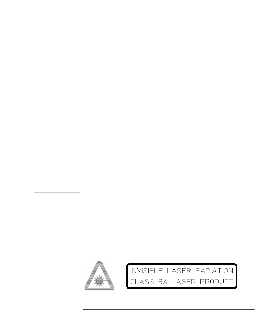
Installation
Connecting to the Network
OR DISCONNECTING OPTICAL CABLES.
• When connecting or disconnecting optical cables between the module
and device-under-test, observe the connection sequences given below.
Connecting: Connect the optical cable to the input of the device-
under-test before connecting to the module’s Optical
Out connector.
Disconnecting: Disconnect the optical cable from the module’s Optical
Out connector before disconnecting from the device-
under-test. Always ensure the shutter closes properly
and covers the laser aperture.
• NEVER examine or stare into the open end of a broken, severed, or disconnected optical cable when it is connected to the module’s Optical
Out connector.
• Arrange for service-trained personnel, who are aware of the hazards
involved, to repair optical cables.
CAUTION 1. Use of controls or adjustments or performance of procedures other than
those specified herein may result in hazardous radiation exposure.
2. Always leave the fibre optic connector dust caps on each connector
when not in use. Before connection is made, always clean the connector
ferrule tip with acetone or alcohol and a cotton swab. Dry the connector
with compressed air. Failure to maintain cleanliness of connectors is
liable to cause excessive insertion loss.
Laser Warning Symbols
The front panel of optical modules Options UH1 and UH2 has the
following label:
CLASS 1 LASER PRODUCT
This label indicates that the radiant energy present in this instrument is
non-hazardous.
The front panel of optical modules Options URU, UKT and USN has
the following label:
2-11
Page 100
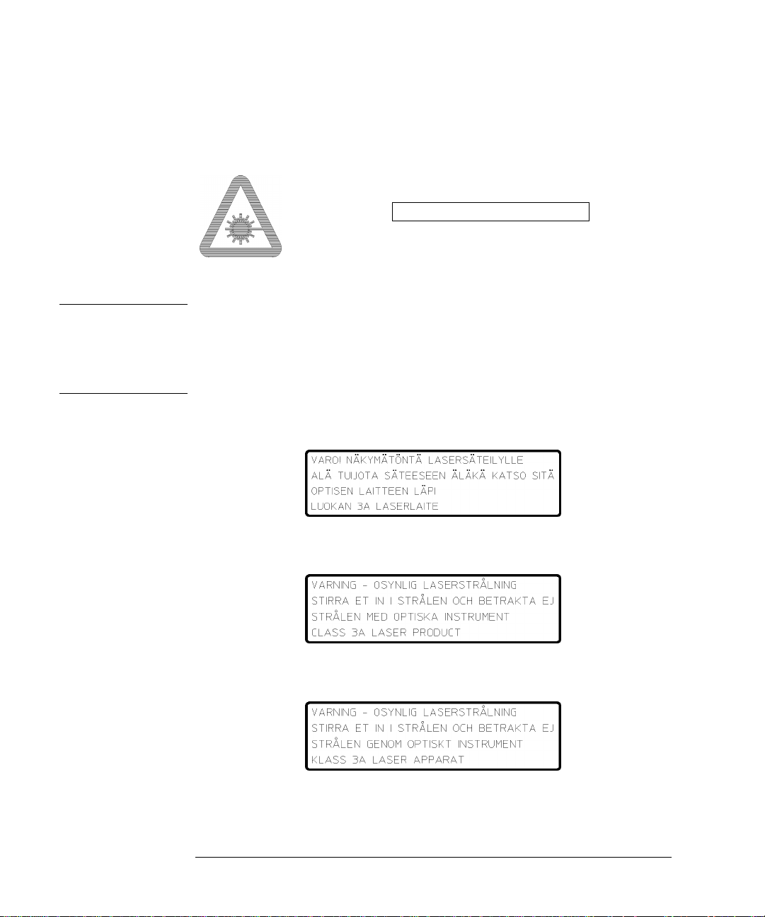
Installation
Connecting to the Network
The front panel of optical modules Options 130 and 131 has the following label
CLASS 3A LASER PRODUCT
WARNING Direct intrabeam viewing of Class 3A laser beams with optical
aids (e.g. binoculars, telescopes) may be hazardous. For laser
emitting in the range from 400nm to 700nm, protection to the
unaided eye is afforded by aversion responses including the blink
reflex.
Swedish and Finnish Labels
2-12
 Loading...