

Page 1

Operating and
Programming Guide
This guide describes how to use and program the Agilent 53147A, 53148A,
and 53149A. The information in this guide applies to instruments having
the number prefix listed below, unless accompanied by a “Manual
Updating Changes” package indicating otherwise.
SERIAL PREFIX NUMBER: US4047 (53147A)
US4048 (53148A)
US4049 (53149A)
Agilent 53147A/148A/149A
Microwave Frequency Counter/
Power Meter/DVM
Page 2
Copyright Agilent
Technologies, Inc. 2001, 2002
All Rights Reserved.
Reproduction, adaptation, or
translations without prior
written permission is
prohibited, except as allowed
under the copyright laws.
Printed: May 2002
Printed in U.S.A.
Manual part number
53147-90009
Certification and Warranty
Certification
Agilent Technologies, Inc.
certifies that this product met
its published specification at the
time of shipment from the
factory. Agilent further certifies
that its calibration measurements
are traceable to the United
States National Institute of
Standards and Technology
(formerly National Bureau of
Standards), to the extent
allowed by the Institute’s
calibration facility, and to the
calibration facilities of other
International Standards
Organization members.
Warranty
Agilent warrants Agilent
hardware, accessories and
supplies against defects in
materials and workmanship for
a period of one year from date of
shipment. If Agilent receives
notice of such defects during the
warranty period, Agilent will, at
its option, either repair or
replace products which prove to
be defective. Replacement
products may be either new or
like-new.
Agilent warrants that
Agilent software will not fail to
execute its programming
instructions, for the period
specified above, due to defects in
material and workmanship
when properly installed and
used. If Agilent receives notice
of such defects during the
warranty period, Agilent will
replace software media which
does not execute its
programming instructions due
to such defects.
For detailed warranty
information, see back matter.
Safety Considerations
General
This product and related
documentation must be
reviewed for familiarization
with this safety markings and
instructions before operation.
Before Cleaning
Disconnect the product from
operating power before cleaning.
Warning Symbols That May
Be Used In This Book
Instruction manual symbol; the
product will be marked with
this symbol when it is necessary
for the user to refer to the
instruction manual.
Indicates hazardous voltages.
Indicates earth (ground)
terminal.
or
Indicates terminal is connected
to chassis when such connection
is not apparent.
Indicates Alternating current.
Indicates Direct current.
Safety Considerations
(cont’d)
WARNING
BODILY INJURY OR DEATH
MAY RESULT FROM
FAILURE TO HEED A
WARNING. DO NOT
PROCEED BEYOND A
WARNING UNTIL THE
INDICATED CONDITIONS
ARE FULLY UNDERSTOOD
AND MET.
CAUTION
Damage to equipment, or
incorrect measurement data,
may result from failure to
heed a caution. Do not
proceed beyond a CAUTION
until the indicated conditions
are fully understood and met.
Safety Earth Ground
An uninterruptible safety earth
ground must be maintained
from the mains power source to
the product’s ground circuitry.
WARNING
WHEN MEASURING POWER
LINE SIGNALS, BE
EXTREMELY CAREFUL AND
ALWAYS USE A
STEP-DOWN ISOLATION
TRANSFORMER WHICH
OUTPUT IS COMPATIBLE
WITH THE INPUT
MEASUREMENT
CAPABILITIES OF THIS
PRODUCT. THIS PRODUCT’S
FRONT AND REAR PANELS
ARE TYPICALLY AT EARTH
GROUND. THUS, NEVER TRY
TO MEASURE AC POWER
LINE SIGNALS WITHOUT AN
ISOLATION TRANSFORMER.
For additional safety and
acoustic noise information,
see back matter.
Agilent Technologies, Inc. 7.C.NL.10.31.00.R1.M.CW6FC
5301 Stevens Creek Boulevard
Santa Clara, California 95052-8059
Page 3

Contents
Contents and Organization xii
Related Documents xiii
Types of Service Available if Instrument Fails xiv
Repackaging for Shipment xv
Product Description xvi
Options xvii
Accessories Supplied and Available xviii
Agilent 53147A/148A/149A Quick Reference Guide xix
1 Getting Started
The Front Panel at a Glance 1-2
The Front Panel Indicators at a Glance 1-3
The Front Panel Menus at a Glance 1-5
The Display Annunciators at a Glance 1-6
The Display Special Characters at a Glance 1-7
The Rear Panel at a Glance 1-8
Operating the Instrument 1-9
Turning the Instrument On 1-11
Turning the Display Backlight Off or On 1-12
Using the Menu 1-13
Displaying the Menu 1-13
Navigating in the Menu and Changing Settings 1-13
Setting the Serial Port Baud Rate (Menu Example) 1-16
Selecting the Counter Input Channel 1-17
Measuring Frequency 1-18
Measuring Relative Frequency 1-20
Offsetting a Frequency Measurement 1-21
Measuring Power 1-23
Selecting a Power Meter Head (Sensor) Model 1-23
Measuring Power 1-25
Selecting the Unit of Measurement for Power 1-26
Measuring Relative Power 1-27
Offsetting a Power Measurement 1-27
Operating and Programming Guide iii
Page 4

Contents
Setting the Measurement Rate 1-29
Setting the Number of Averages 1-30
Setting the Resolution for Frequency Measurements 1-31
Measuring Voltage 1-33
2 Operating Your Instrument
Introduction 2-2
Chapter Summary 2-2
How this Instrument Works for You 2-3
Summary of the Measurement Sequence 2-4
Using the Selection Keys 2-5
Sequencing Through the Menu 2-5
Numeric Entry 2-6
Changing States 2-6
Using the Clear and Reset/Local Keys 2-8
Acknowledging Messages 2-8
Other Function Selection Keys 2-9
Measuring Frequency 2-11
Setting the Resolution and Measurement Rate 2-13
Setting the Resolution 2-13
Resolution Setting Example 2-14
Setting the Measurement Rate 2-15
Rate Setting Example 2-15
Setting the Number of Averages 2-16
Averages Setting Example 2-16
Measuring Relative Frequency 2-19
Relative Frequency Example 2-19
Offsetting a Frequency Measurement 2-20
Frequency Offset Example 2-20
Measuring Power 2-23
Selecting a Power Head (Sensor) 2-23
Making a Power Measurement 2-23
Power Measurement Example 2-24
Modifying and Adding Calibration Factor Tables 2-27
Calibration Table Modification Example 2-28
iv Operating and Programming Guide
Page 5

Contents
Measuring Relative Power 2-38
Relative Power Example 2-38
Offsetting a Power Measurement 2-39
Power Offset Example 2-39
Measuring Voltage 2-42
Voltage Measurement Example 2-42
Using the Menu 2-43
Navigating in the Menu and Changing Settings 2-45
Reference Oscillator (REF OSC) 2-46
Power Reference (PWR REF) 2-47
Save User Settings (SAVE) 2-47
Recall User Settings (RECALL) 2-47
Channel 1 Low-Pass Filter (CH1 LPF) 2-47
Frequency Modulation (FM) 2-48
RS-232 Serial Port Data Rate (BAUD) 2-48
Preset 2-48
Model Number, Firmware Version, Serial Number,
and Option Codes 2-49
Operating Hours (OP HOURS) 2-49
Battery Voltage (BATT VOLTAGE) 2-50
Do Self Test 2-50
Power Head Selection (HEAD) 2-50
GPIB Address (GPIB ADDR) 2-50
3 Programming
Introduction 3-2
Chapter Summary 3-3
How to Use This Chapter 3-5
New Users 3-5
What You Should Understand 3-5
Learning to Program the Instrument 3-6
Experienced Programmers 3-6
Applications 3-7
Assumptions 3-8
Related Documentation 3-9
Front Panel to SCPI Command Map 3-11
Operating and Programming Guide v
Page 6

Contents
Command Summary 3-16
SCPI Conformance Information 3-16
IEEE 488.2 Common Commands 3-17
Agilent 53147A/148A/149A SCPI Subsystem Commands 3-20
Std/New Column 3-20
Parameter Form Column 3-20
*RST Response 3-28
Programming the Instrument for Remote Operation 3-30
Connecting the Instrument to a Computer 3-31
Connecting With the GPIB 3-31
Configuring the GPIB 3-31
Changing the GPIB Address 3-32
IEEE 488.1 Interface Capabilities 3-32
Connecting With the RS-232 Serial Interface 3-33
Making an RS-232 Cable 3-33
Assembling the DB-25/RJ12 Adapter and the Cable 3-34
Connecting with the Serial Interface 3-37
Remote/Local Operation 3-37
Overview of Command Types and Formats 3-38
Common Command Format 3-38
SCPI Command and Query Format 3-38
Elements of SCPI Commands 3-39
Subsystem Command Syntax 3-39
Common Command Syntax 3-39
Abbreviated Commands 3-40
Keyword Separator 3-40
Optional Keyword 3-40
Parameter Types 3-41
Parameter Separator 3-43
Query Parameters 3-43
Suffixes 3-43
Suffix Elements 3-43
Suffix Multipliers 3-44
Command Terminator 3-44
vi Operating and Programming Guide
Page 7

Contents
Using Multiple Commands 3-45
Program Messages 3-45
Program Message Syntax 3-45
Overview of Response Message Formats 3-47
Response Messages 3-47
Response Message Syntax 3-47
Response Message Data Types 3-49
Status Reporting 3-51
Status Byte Register and
Service Request Enable Register 3-53
Status Byte Register 3-53
Service Request Enable Register 3-55
Standard Event Status Register Group 3-56
Standard Event Status Register 3-56
Standard Event Status Enable Register 3-58
The Operation and Questionable Data Status Register Groups 3-59
Condition Register 3-60
Transition Filter 3-60
Event Register 3-61
Event Enable Register 3-62
Operation Status Register Group 3-63
Questionable Data Status Register Group 3-65
Programming the Instrument
for Status Reporting 3-67
Determining the Condition of the Instrument 3-67
Resetting the Instrument and Clearing
the Remote Interface—Example 1 3-68
Using the Standard Event Status Register to
Trap an Incorrect Command—Example 2 3-68
Event Status Register 3-68
Using the Operation Status Register to Alert the Computer When
Measuring is Complete—Example 3 3-69
Operation Status Register 3-69
Programming the Instrument to Display Results 3-72
Configuring the Instrument's Display 3-72
Operating and Programming Guide vii
Page 8

Contents
Commands for Displaying Results 3-73
Command for Displaying Raw Results 3-73
Commands for Displaying Relative Results 3-73
Commands for Enabling and Disabling the Display 3-73
Programming the Instrument to
Synchronize Measurements 3-74
Synchronizing Measurement Completion 3-74
Resetting the Instrument and Clearing the Interface 3-74
Using the *WAI Command 3-75
Using the *OPC? Command 3-76
Using the *OPC Command to Assert SRQ 3-76
Writing SCPI Programs 3-78
Programming Examples 3-80
Using BASIC 3-80
Sending Double-Quoted and Single-Quoted Strings 3-80
Using C 3-81
List of the Programming Examples 3-81
Making a Frequency Measurement (BASIC) 3-82
Making a Frequency Measurement (QuickBASIC) 3-83
Making a Frequency Measurement (C) 3-84
Command Reference 3-86
:ABORt Command 3-88
:CALibration Subsystem 3-89
:DISPlay Subsystem 3-95
Group Execute Trigger (GET) 3-97
:INITiate Subsystem 3-98
:INPut Subsystem 3-99
:MEASure Subsystem 3-100
Measurement Instructions
(:CONFigure, :FETCh, :MEASure, :READ) 3-100
Descriptions of the Measurement Functions 3-106
How to Use the Measurement Instruction Commands 3-109
Using :MEAsure 3-109
Using :CONFigure with :READ? 3-110
viii Operating and Programming Guide
Page 9

Contents
:MEMory Subsystem 3-111
[:SENSe] Subsystem 3-113
[:SENSe]:FUNCtion Subtree 3-118
[:SENSe]:POWer Subtree 3-120
[:SENSe]:ROSCillator Subtree 3-121
:STATus Subsystem 3-122
:STATus:OPERation Subtree 3-122
:STATus:QUEStionable Subtree 3-127
:SYSTem Subsystem 3-130
:SYSTem:COMMunicate Subtree 3-130
:TRIGger Subsystem 3-133
:UNIT Subsystem 3-134
Common Commands 3-135
*CLS (Clear Status Command) 3-135
*DDT <arbitrary block>
(Define Device Trigger Command)
*DDT?
(Define Device Trigger Query) 3-136
*ESE (Standard Event Status Enable Command)
*ESE? (Standard Event Status Enable Query) 3-137
*ESR? (Event Status Register Query) 3-139
*IDN? (Identification Query) 3-140
*IST? (Instrument Status) 3-140
*OPC (Operation Complete Command) 3-141
*OPC? (Operation Complete Query) 3-141
*PRE (Parallel Poll Enable Register)
*PRE? (Parallel Poll Enable Register Query) 3-142
*RCL (Recall Command) 3-142
*RST (Reset Command) 3-143
*SAV (Save Command) 3-144
*SRE (Service Request Enable Command)
*SRE? (Service Request Enable Query) 3-145
*TRG
(Trigger Command) 3-147
*TST? (Self-Test Query) 3-148
*WAI (Wait-to-Continue Command) 3-149
Operating and Programming Guide ix
Page 10

Contents
Errors 3-150
Reading an Error 3-150
Error Queue 3-151
Error Types 3-152
No Error 3-152
Command Error 3-152
Execution Error 3-153
Device-Specific or Instrument-Specific Error 3-153
Query Error 3-154
Error List 3-154
4 Specifications
Introduction 4-2
Measurement Specifications and Characteristics 4-3
A Rack Mounting the Instrument
Rack Mounting the Instrument A-2
B Messages
Overview B-2
Status Messages B-2
Self-Test Messages B-3
Error Messages B-4
C Using the Battery Option
Overview C-2
Operating the Instrument from the Batteries C-2
Operating the Instrument
from a DC Power Source C-4
Replacing the Batteries C-5
Removing the Batteries C-5
Installing Batteries C-5
Charging the Batteries C-8
Precautions C-9
Index
x Operating and Programming Guide
Page 11

In This Guide
This book is the Operating and Programming Guide for the
Agilent 53147A, 53148A, and 53149A. It consists of a table of contents,
this preface, a quick-reference guide, four chapters, three appendices,
and an index.
This preface contains the following information:
• Contents and Organization pg. xii
• Related Documents pg. xiii
• Types of Service Available if Instrument Fails pg. xiv
• Repackaging for Shipment pg. xv
• Product Description pg. xvi
• Options pg. xvii
• Accessories Supplied and Available pg. xviii
• Manuals Supplied pg. xviii
Operating and Programming Guide xi
Page 12

In This Guide
Contents and Organization
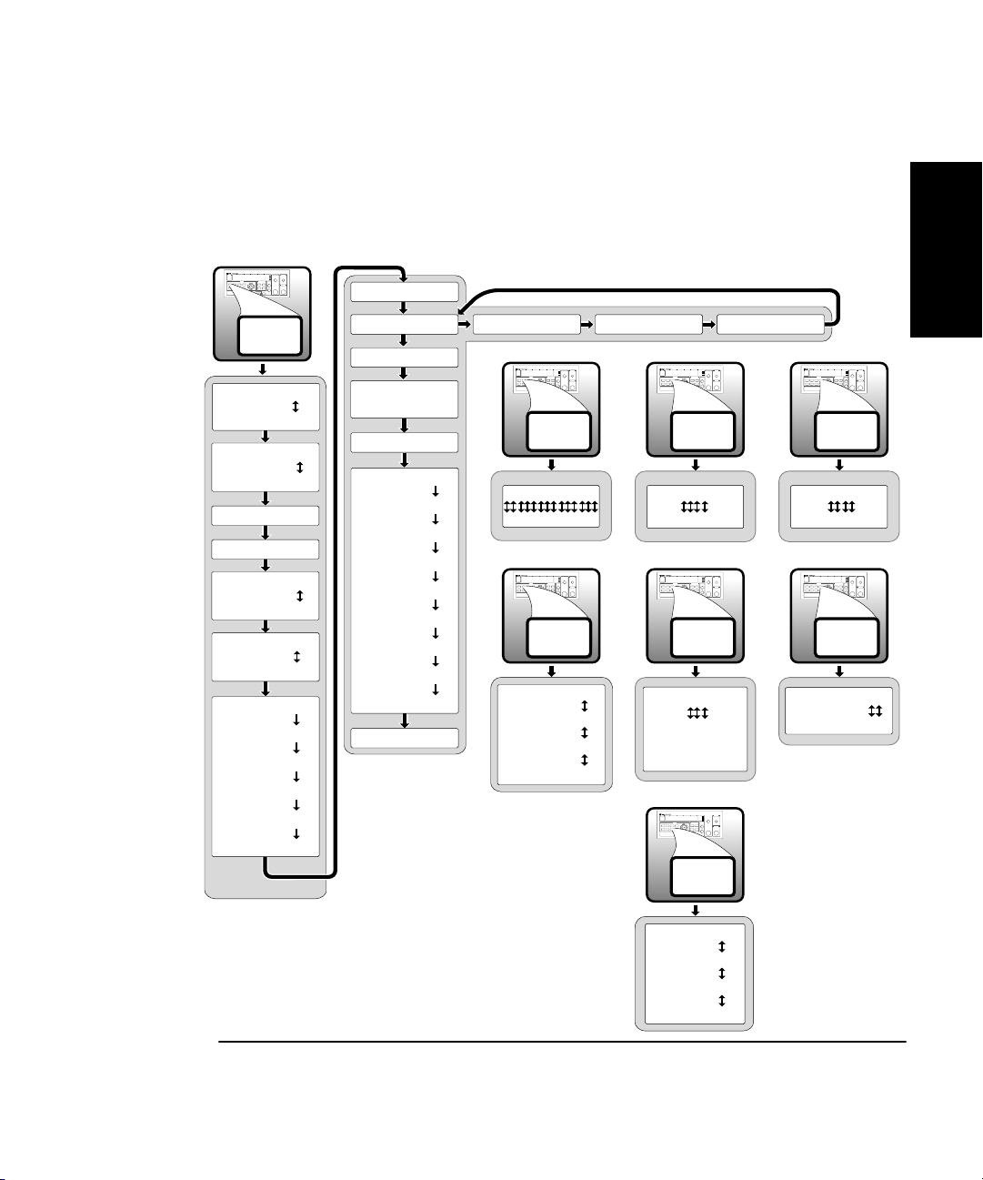
The Quick Reference Guide consists of a Menu Tree (tear-out sheet)
that serves as a tool to trigger your memory or get you quickly
reacquainted with the instrument.
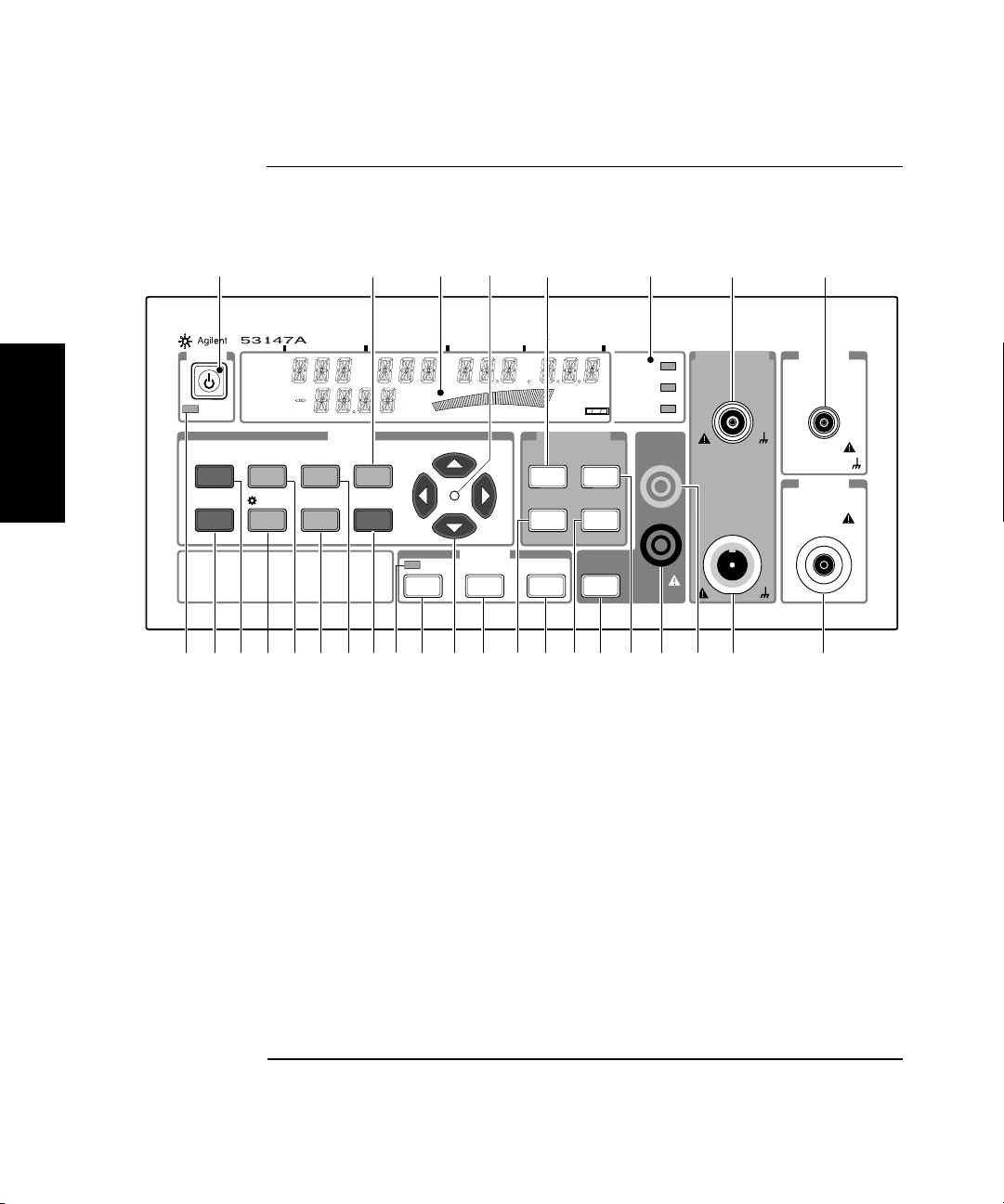
Chapter 1 Getting Started is a quick-start guide that gives you a
brief overview of the instrument’s keys, indicators, menus, display,
and connectors. A graphical procedure for performing a measurement
is also provided.
Chapter 2 Operating Your Instrument is an operator’s reference.
You are given an overview of each group of front-panel keys, operating
functions, and menus followed by a series of exercises that guide you
through the operation of the instrument.
Chapter 3 Programming provides information that you can use to
remotely operate the instrument.
Chapter 4 Specifications lists the specifications and characteristics of
the instrument.
Appendix A Rack Mounting the Instrument provides rack-mounting
procedures for the instrument.
Appendix B Messages lists and explains all of the messages that are
displayed on the instrument’s front panel and/or sent over the RS-232
serial interface.
Appendix C Using the Battery Option explains how to use the
instrument with the Battery option.
Index
xii Operating and Programming Guide
Page 13

In This Guide
Related Documents
For more information on frequency counters, refer to the following Series
200 Application Notes:
• Fundamentals of Electronic Frequency Counters,
Application Note 200, Agilent part number 02-5952-7506.
• Understanding Frequency Counter Specifications,
Application Note 200-4, Agilent part number 02-5952-7522.
• Fundamentals of Time and Frequency Standards,
Application Note 52-1, Agilent part number 02-5952-7870.
Operating and Programming Guide xiii
Page 14

In This Guide
Types of Service Available if Instrument Fails
If your instrument fails within one year of original purchase, Agilent will
repair it free of charge. If your instrument fails after your one-year
warranty expires, Agilent will repair it, or you can repair it yourself.
There are three types of repair services:
• Standard repair service—if downtime is not critical.
• Express Repair/Performance Calibration Service—if downtime is
critical.
• Owner repair—repair the unit yourself using the Assembly-Level
Service Guide.
Standard Repair Services (Worldwide)
Contact your nearest Agilent Service Center to arrange to have your
instrument repaired.
Express Repair/Performance Calibration
Service (USA Only)
If downtime is critical, you can receive your repaired instrument via
overnight shipment. Just call 1-800-403-0801 and ask for Express
Repair/Performance Calibration Service. When your instrument is
repaired, it will be returned via overnight shipment.
Repair Instrument Yourself
If you choose to repair the instrument yourself or would like more details
on self test and calibration, use the procedures in the Assembly-Level
Service Guide.
xiv Operating and Programming Guide
Page 15

In This Guide
Repackaging for Shipment
For the Express Repair/Performance Calibration Service described above,
return your failed instrument to the designated Agilent Service Center,
using the instrument’s original shipping carton (if available). Agilent
notifies you when your failed instrument is received.
If the instrument is to be shipped to Agilent for service or repair, be sure
you do the following:
• Attach a tag to the instrument identifying the owner and indicating
the required service or repair. Include the instrument model number
and full serial number.
• Place the instrument in its original container (if available) with
appropriate packaging material.
• Secure the container with strong tape or shipping bands.
If the original shipping container is not available, place your unit in a
container with at least 4 inches of compressible packaging material
around all sides of the unit. Use static free packaging materials to avoid
additional damage to your unit.
Agilent suggests that you always insure shipments.
Operating and Programming Guide xv
Page 16

In This Guide
Description of the Microwave Frequency
Counter/Power Meter/DVM
The Agilent 53147A, 53148A, and 53149A are capable of measuring
frequencies from 10 Hz to 125 MHz on Channel 1 and from 50 MHz to
20 GHz (53147A), 26.5 GHz (53148A), and 46 GHz (53149A) on Channel 2.
These instruments are also capable of measuring power (the power and
frequency ranges for power measurement are dependent on the powersensor model used) and DC voltages up to ±50 VDC. All three instruments
have a maximum frequency resolution of 1 Hz.
The Agilent 53147A/148A/149A provide GPIB and RS-232 serial
interfaces and are suitable for field, bench-top, and ATE operation.
The basic measurement functions of the Agilent 53147A/148A/149A
includes Frequency, Relative Frequency, Frequency Offset, Power, Power
Offset, Relative Power, and DC voltages. All of these features are
accessible from the front panel and over the GPIB and RS-232 interfaces.
The Agilent 53147A/148A/149A includes the following additional
measurement functions and features that are designed specifically for
manufacturing and service applications:
• 1, 2, 5, and 10 MHz external reference capability
• Optional high-stability oven oscillator for high-accuracy needs and
lengthened calibration cycles
• Frequency and power offset capabilities for relative measurements
• SCPI programming capability
• Battery and dc input option for operation in locations where AC
power is unavailable
• Optional soft carrying case for safe transportation and mobile use
Programmable control is performed via a GPIB or an RS-232 serial
interface. The GPIB and RS-232 ports are standard for the Agilent
53147A, 53148A, and 53149A.
xvi Operating and Programming Guide
Page 17

In This Guide
Options
The options available for the Agilent 53147A/148A/149A are listed below.
Specifications for the options are listed in Chapter 3, “Programming.”
Options ordered with the instrument are installed at the factory and are
ready for operation on delivery. Refer to the “Retrofitting Options” chapter
in the Agilent 53147A/148A/149A Assembly-Level Service Guide for
information on installing options in the field.
Hardware
• High Stability Oven Timebase, Option 001
• Battery/DC Power Input, Option 002
• Rack Mount Kit, Option 1CM
• Soft Carrying Case, Option 007
Retrofit
Options 001 and 002 can be installed only by authorized Agilent
Technologies Repair Centers.
Operating and Programming Guide xvii
Page 18

In This Guide
Accessories Supplied and Available
Accessories Supplied
• Power cord, 2.3 meters (Part number dependent upon destination country)
• Power sensor cable (Agilent 11730A)
• DVM test leads (Agilent 34132B)
Accessories Available
• Soft Carrying Case (Agilent P/N 53147-80016)
• Automotive Power Adapter (Agilent P/N 53150-60214)
• Battery (Agilent P/N 53150-80010)
• GPIB Cables (Agilent 10833A/B/C/D)
• RS-232 Cable (Agilent P/N 53150-60215)
• Power Sensors (Agilent 8480 series)
Manuals Supplied
Agilent 53147A/148A/149A Operating and Programming Guide
(Agilent P/N 53147-90009)
Agilent 53147A/148A/149A Assembly-Level Service Guide
(Agilent P/N 53147-90010)
xviii Operating and Programming Guide
Page 19

Agilent 53147A/148A/149A
Quick Reference Guide
The Quick Reference Guide is designed for experienced
users of the Agilent 53147A, 53148A, and 53149A. It is
intended to be used as a tool to trigger your memory.
If you are using the instrument for the first time, it is
recommended that you at least read Chapter 1, “Getting
Started,” first.
The Quick Reference Guide, which follows this page,
consists of a menu tree that may be torn out of the guide
for external use.
Reference
Quick
xix
Page 20

Quick
Reference
xx
Page 21
Agilent 53147A/148A/149A
Frequency Counter/Power Meter/DVM
GHz MHz kHz Hz
Menu
Reset/
Local
REF OSC > INT
REF OSC > EXT
PWR REF > OFF
PWR REF > ON
SAVE > 0 to 9
RECALL > 0 to 9
CH1 LPF > OFF
CH1 LPF > ON
FM > AUTO
FM > OFF
BAUD > 9600
BAUD > 4800
BAUD > 2400
BAUD > 1200
BAUD > 19200
BAUD > 14400
PRESET
53147A >
< 2060162-00 >
OP 9999 HRS
BATT VOLTAGE
0.0
DO SELF TEST
HEAD > OFF
HEAD > 8487A
HEAD > 8485A
HEAD > 8482A
HEAD > 8481D
HEAD > 8481A
CUSTOMHEAD >1
CUSTOMHEAD >2
CUSTOMHEAD >3
GPIB ADDR > 0 to 30
< US 000 001 11 >
GHz MHz kHz Hz
Freq
Offset
Resol
00 000 000 000 000
49 999 999 999 999
GHz MHz kHz Hz
Freq
Offset
Resol
RESOL 1 HZ
RESOL 10 KHZ
RESOL 100 KHZ
RESOL 1 MHZ
* *.* = Counter
frequency
<OPTNS -- -- -- -- >
GHz MHz kHz Hz
Cal
Factor
Freq
150.0
050.0
GHz MHz kHz Hz
Cal
Factor
Freq
* *.*
00.0
max.
GHz MHz kHz Hz
Rate
+ / –
GHz MHz kHz Hz
Pwr
Offset
Avg
± 00.00
± 99.99
GHz MHz kHz Hz
Pwr
Offset
Avg
AVERAGES 01
AVERAGES 99
Reference
Reference
Quick
Quick
RATE FAST
RATE MED
RATE SLOW
RATE HOLD
QR-1
Page 22

Quick
Reference
QR-2
Page 23

1
Getting Started
Page 24
Chapter 1 Getting Started
The Front Panel at a Glance
The Front Panel at a Glance
1951820
4
COUNTER
Offset
On/Off
6 7 8
20 GHz Counter/Power Meter/DVM
Hz
Ext Rel
Rate Rmt SRQ
Error
Shift
POWER METER
dBm/W
Display
Power
Rel Pwr
Offset
On/Off
Rel FreqChan
16
Hold
Pwr Ref
Zero
Store
Cal
Display
DVM
141517
Counter
Power
Meter
DVM
DAMAGE
13
DVM
±60 VDC
12 91011
+
–
POWER METER
OUTPUT
Power Ref.
1.00mW 50MHz
INPUT
Do NOT Exceed
Sensor Max Power
COUNTER
CHANNEL 1
10 Hz to 125 MHz
1MΩ
DAMAGE
+30 dBm
COUNTER
CHANNEL 2
50MHz to 20 GHz
DAMAGE
+27 dBm
50Ω
15 Calibrate / Store key
16 Relative Frequency key
17 Power Offset On/Off / Relative Power key
18 Frequency Offset On/Off key
19 Selection (arrow) keys
20 Counter Channel Selection key
21 Gate indicator
22 Enter key
23 Frequency / Calibration Factor key
24 Sign change (+/–) / Rate key
25 Resolution / Frequency Offset key
26 Clear / Display Backlight On/Off key
27 Reset/Local / Menu key
28 Shift key
29 Standby indicator
13
POWER
1
Menu
Standby
Reset/
Local
Shift
Ch 12
Rel Freq
Offset
Avg On
Rel Pwr
Offset
Freq
Offset
Resol
On/Off
Clear
Cal
Factor
Freq
Rate
+ / -
29
GHz
MODIFY
Pwr
Offset
Avg
Enter
2
2122232425262728
MHz kHz
dB
dBm
Watts
mW
uW
nW
%
Gate
Select
1 Power / Standby switch
2 Average / Power Offset key
3 LCD display
4 Selection-keys-active indicator
5 Display Power / dBm/W key
6 Instrument-function indicators
(Counter / Power Meter / DVM)
7 Power Reference Output connector
8 Channel 1 input connector
Channel 2 input connector
9
10 Power Meter Input connector
11 DVM + connector
12 DVM – connector
13 Zero key
14 Display DVM key
1-2 Operating and Programming Guide
Page 25
Chapter 1 Getting Started
The Front Panel Indicators at a Glance
The Front Panel Indicators at a Glance
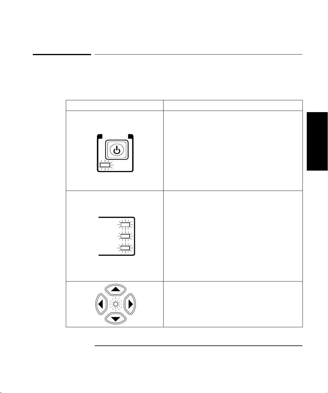
There are five front-panel LED indicators. These are listed and described
in the following table.
Indicator Description
The Standby indicator is lit whenever the power
cord is connected (or the battery option is supplying
power), and the POWER switch on the front panel is
POWER
Standby
OFF (out). During Standby, most of the instrument’s
circuits do not receive power. The cooling fan and the
timebase are powered to maintain temperature
stability in the timebase components, and if the
Battery option is installed, the battery-charging
circuits are powered. When you press the POWER
switch on the front panel, the Standby indicator goes
off, and all of the instrument’s circuits receive power.
1
The function LEDs light to indicate which of the
instrument’s functions are displayed. If frequency is
the only measurement displayed (the Power Meter
and the DVM are disabled), only the Counter LED is
Counter
Power
Meter
DVM
lit. If both frequency and power measurements are
displayed (the Counter and the Power Meter are
enabled), the Counter and Power Meter LEDs are lit.
If a voltage reading and a power reading are displayed
(the DVM and the Power Meter are enabled), the
Power Meter and DVM LEDs are lit. If only a
voltage reading is displayed (the DVM is the only
function enabled), the DVM LED is lit, and the
Counter and Power Meter LEDs are not lit.
When the LED indicator between the arrow keys
flashes, the arrow keys can be used to navigate and
change values in menus.
When you make a change in a menu, always press
the Enter key to save the setting and exit the menu.
Operating and Programming Guide 1-3
Page 26
Chapter 1 Getting Started
COUNT
Gate
Chan
Select
The Front Panel Indicators at a Glance
Indicator Description
The Gate LED indicator flashes to indicate the rate
at which Counter measurements are triggered.
The flash rate of the LED varies with the settings of
the measurement rate (Rate key) and the Counter
measurement resolution (Resol key). The flash rate
of the LED provides a rough indication of the
number of Counter measurements that are being
taken in a given period of time.
1
NOTE It is normal for the fan to run when the instrument is in Standby mode.
Power is supplied to the timebase whenever the instrument is connected
to a power source, and the fan runs to cool the power supply.
1-4 Operating and Programming Guide
Page 27
Chapter 1 Getting Started
The Front Panel Menus at a Glance
The Front Panel Menus at a Glance
Shift
Menu
Reset/
Local
REF OSC > INT
REF OSC > EXT
PWR REF > OFF
PWR REF > ON
SAVE > 0 to 9
OP 9999 HRS
BATT VOLTAGE
0.0
RECALL > 0 to 9
CH1 LPF > OFF
CH1 LPF > ON
FM > AUTO
FM > OFF
DO SELF TEST
HEAD > OFF
HEAD > 8487A
HEAD > 8485A
HEAD > 8482A
BAUD > 9600
BAUD > 4800
HEAD > 8481D
HEAD > 8481A
BAUD > 2400
BAUD > 1200
BAUD > 19200
BAUD > 14400
GPIB ADDR > 0 to 30
PRESET
53147A >
< 2060162-00 >
RATE FAST
RATE MED
RATE SLOW
RATE HOLD
CUSTOMHEAD >1
CUSTOMHEAD >2
CUSTOMHEAD >3
Rate
+ / –
< US 400 001 11 >
<OPTNS -- -- -- -- >
Freq
Offset
Resol
RESOL 1 HZ
RESOL 10 KHZ
RESOL 100 KHZ
RESOL 1 MHZ
1
Operating and Programming Guide 1-5
Page 28
Chapter 1 Getting Started
The Display Annunciators at a Glance
The Display Annunciators at a Glance
GHz
MHz
kHz
Hz
Ch 12
Rel Freq
Offset
Avg On
Rel Pwr
Offset
1
Annunciator
Ch 1 or Ch 2
Freq
Rel Freq
Freq
Description
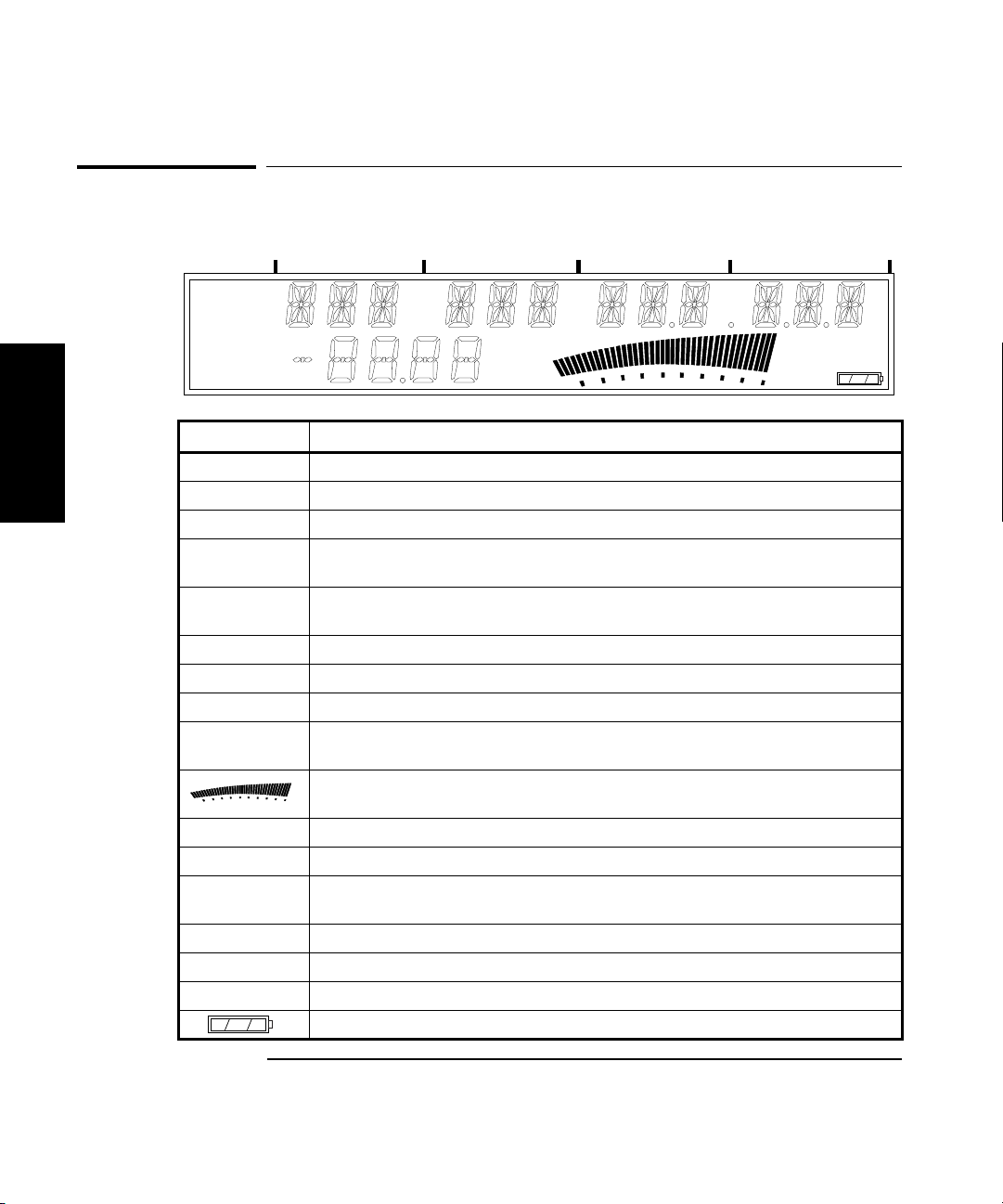
Indicates which channel is selected to measure an input signal.
Indicates that the value displayed is a frequency reading.
The displayed frequency value is relative to a previously stored value.
The displayed frequency value is offset by a previously entered frequency value.
dB
dBm
Watts
mW
uW
%
nW
Offset
Avg On
The displayed measurement value is the result of a number of individual
measurements that have been averaged.
Pwr
Rel Pwr
Pwr Offset
dB, dBm, Watts,
mW,
µW, nW, %
The instrument is set to measure Power (Power Meter is on).
The displayed power measurement is relative to a previously stored power value.
The displayed power value is offset by a previously entered power value.
Indicates the unit of measurement for the currently displayed power value.
Provides a real-time analog representation of the Power measurement (intended for
peaking and similar procedures).
Ext Ref
Hold
Rmt, SRQ
The Counter is using an external reference Timebase for frequency measurements.
Indicates the instrument is in Hold (single-measurement) mode.
Shows the current state of the GPIB interface
(Rmt = Remote operation via GPIB; SRQ = Service ReQuest).
Error
Shift
Pwr Ref
Indicates that a front-panel key command is unacceptable in the current context.
Indicates that all front-panel keys are redefined to the function printed above the key.
Indicates that the 1 mW power reference output is turned on.
Shows the amount of charge in the batteries (if the Battery option is installed).
Ext Ref
Hold
Rate Rmt SRQ
Error
Pwr Ref
Shift
1-6 Operating and Programming Guide
Page 29
Chapter 1 Getting Started
The Display Special Characters at a Glance
The Display Special Characters at a Glance
Special
Characters
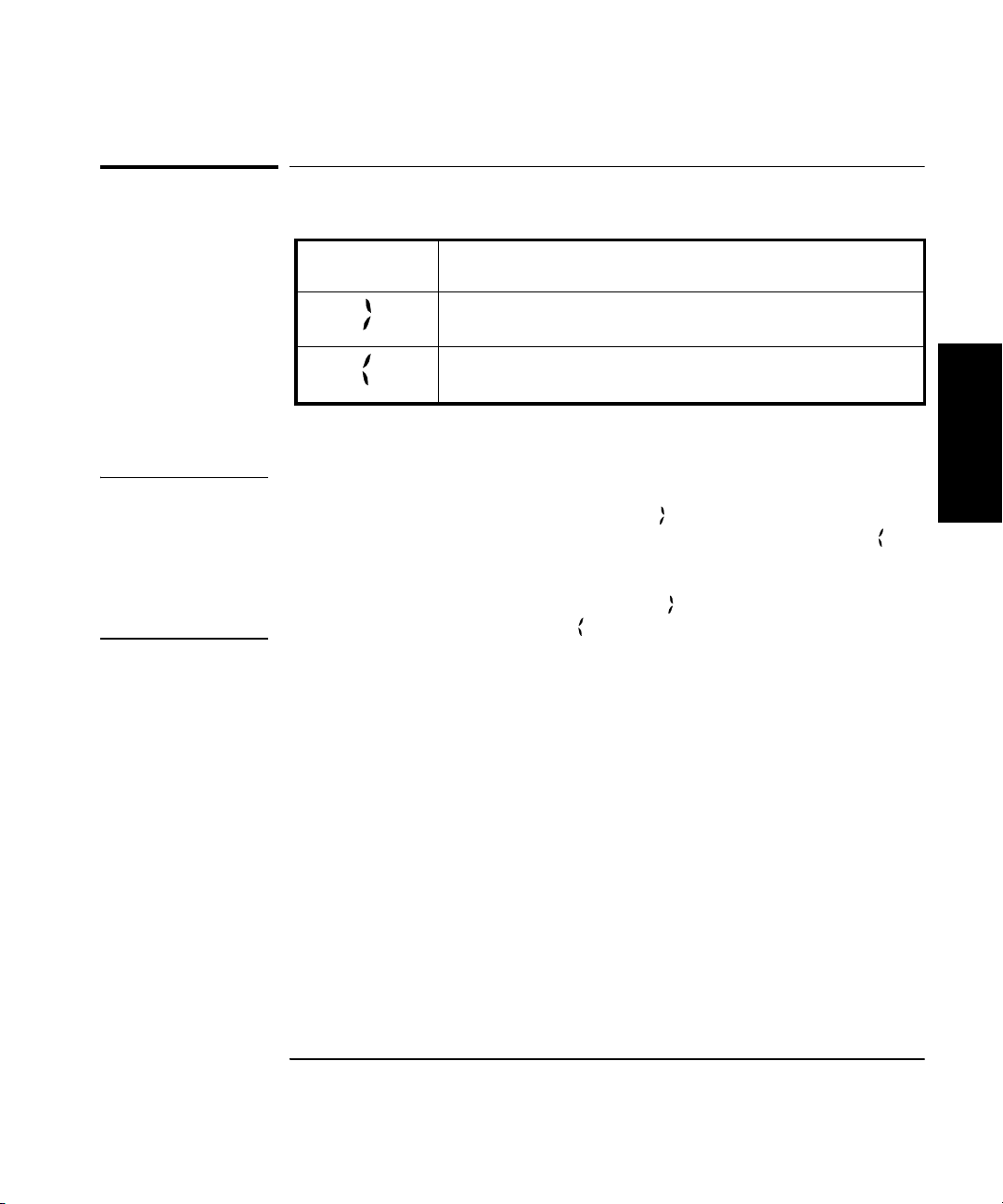
Points to the current value for a Menu setting.
Indicates that the value for the current Menu setting can be
changed using the selection (arrow) keys.
NOTE The special characters shown above are intended to help you navigate
within the Menu. When the right pointer ( ) is flashing, it indicates the
current setting for the selected Menu option. When the left pointer ( ) is
flashing, it indicates that you can use the selection (arrow) keys to change
the setting for the current Menu option. To switch between the two, press
the right arrow key when the right pointer ( ) is flashing, or press the left
arrow key when the left pointer ( ) is flashing.
Description
1
Operating and Programming Guide 1-7
Page 30
Chapter 1 Getting Started
The Rear Panel at a Glance
The Rear Panel at a Glance
5
Counter/ Power Meter/ DVM
Standard
Main Power
AC POWER
90-130 VAC 50/60/400 Hz
190-230 VAC 50/60 Hz
21
RS-
232
3
4
In or Out
!
OPTIONS
001 Oven Time Base
002 Battery
GPIB
Auxiliary
Agilent
!
Reference 10 MHz
FUSE
1.0A
250V
1
Made in U.S.A.
of domestic and foreign content
9
Counter/ Power Meter/ DVM
Made in U.S.A.
of domestic and foreign content
Battery
Battery
Charging
EXT DC
11 to 18 VDC
+
10
11
With
Battery Option
WARNING:
8
AC POWER
90-130 VAC 50/60/400 Hz
190-230 VAC 50/60 Hz
WARNING:
To avoid electrical shock:
Do not remove covers.
7
21
Main Power
RS-
232
To avoid electrical shock:
Do not remove covers.
No user serviceable parts inside.
Refer all servicing to qualified personnel.
3
Reference 10 MHz
In or Out
FUSE
1.0A
250V
No user serviceable parts inside.
Refer all servicing to qualified personnel.
6
!
OPTIONS
001 Oven Time Base
002 Battery
GPIB
4
Auxiliary
This unit must be earth grounded.
!
This unit must be earth grounded.
Agilent
Agilent
Made in U.S.A.
BATTERY PACK
of domestic and foreign content
8
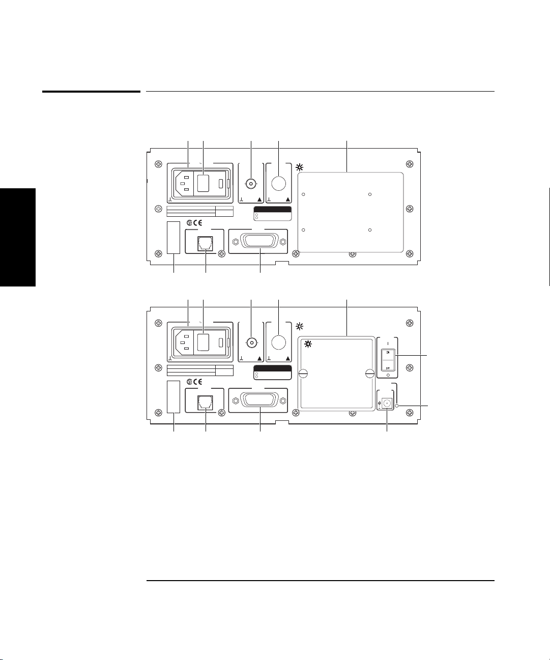
1 AC Input/Power module (Senses
incoming voltage and adjusts
automatically)
2 Fuse Holder (behind door)
3 External Reference connector (BNC)
1, 2, 5, 10 MHz Input, 10 MHz Output
4 Auxiliary connector (reserved) *
5 Battery option cover plate
7
6
6 GPIB Interface connector (IEEE-488.2)
7 RS-232 Interface connector (RJ12)
8 Serial number plate
9 Battery sled (Battery option only)
10 Battery power switch (Battery option only)
11 Battery Charging LED (Battery option only)
12 EXT DC power-input connector (Battery option only)
* The Auxiliary connector is not installed on standard production units.
1-8 Operating and Programming Guide
12
Page 31

Chapter 1 Getting Started
Operating the Instrument
Operating the Instrument
The procedures in this section are designed to familiarize you with the
instrument’s features and controls. Agilent suggests that you follow the
steps for each of these procedures, even if you do not presently need to
make any measurements or to adjust any of the instrument’s settings.
The following procedures are provided:
• Turning the Instrument On
• Turning the Display Backlight Off or On
• Selecting an Input Channel
• Using the Menu
• Setting the Serial Port Baud Rate
• Measuring Frequency
• Measuring Relative Frequency
• Offsetting a Frequency Measurement
• Setting the Power Head Model Number
• Measuring Power
• Measuring Relative Power
• Offsetting a Power Measurement
• Setting the Measurement Rate
• Setting the Number of Averages
• Setting the Resolution
• Measuring Voltage
1
Operating and Programming Guide 1-9
Page 32
Chapter 1 Getting Started
Operating the Instrument
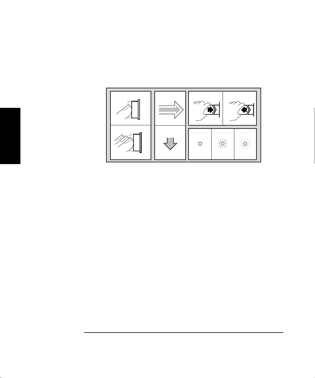
The following legend defines the meanings of the icons used throughout
this chapter.
Legend
1
2
3
4
1
1 Press key one
time and release
2 Multiple key
presses
3 Result
4 Auto operation
5 Connect signal
6 Disconnect signal
56
798
7 Indicator off
8 Indicator on
9 Indicator flashing
1-10 Operating and Programming Guide
Page 33
Chapter 1 Getting Started
Operating the Instrument
Turning the Instrument On
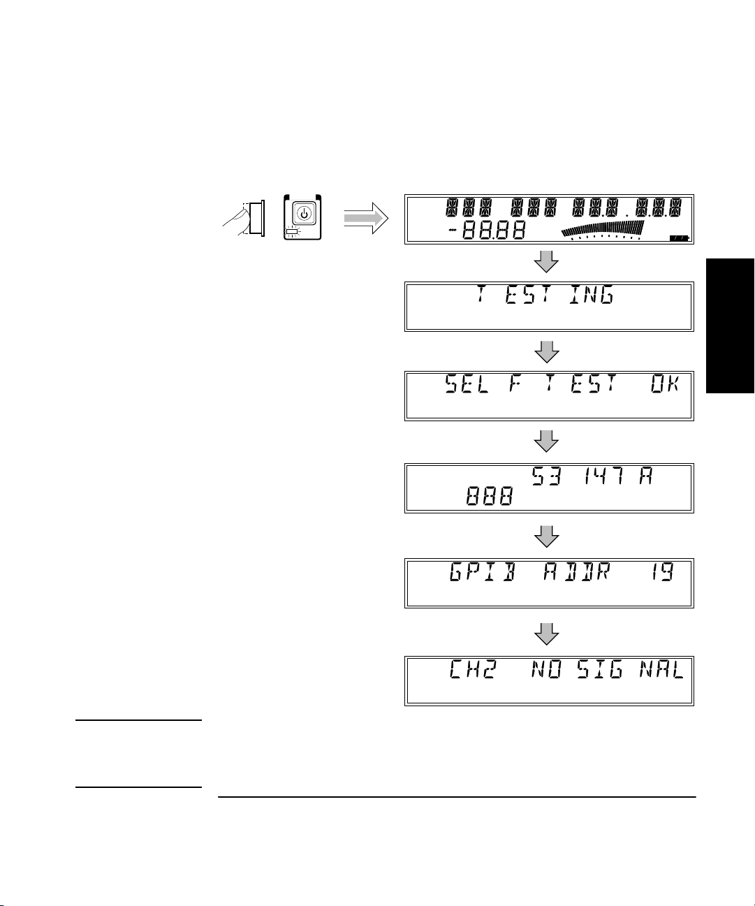
To turn on the instrument, press and release the POWER button on the
front panel.
POWER
Standby
Ch 12
Rel Freq
Offset
Avg On
Rel Pwr
Offset
Ext Ref
dB
dBm
Watts
mW
uW
%
nW
Hold
Rate Rmt SRQ
Pwr Ref
Error
Shift
1
Ch 2
Freq
NOTE If a signal was applied to the Counter’s Channel 2 input connector prior
to turning on the instrument, CH2 NO SIGNAL is displayed momentarily.
As soon as the Counter acquires the input signal, it displays the signal’s
value.
Operating and Programming Guide 1-11
Page 34
Chapter 1 Getting Started
Operating the Instrument
NOTE The internal Reference Oscillator requires 15 minutes to reach a stable
operating temperature. Since the Reference Oscillator receives power only
when the instrument is on or in Standby mode, no measurements should
be taken unless the instrument has been receiving power for at least that
amount of time.
Turning the Display Backlight Off or On
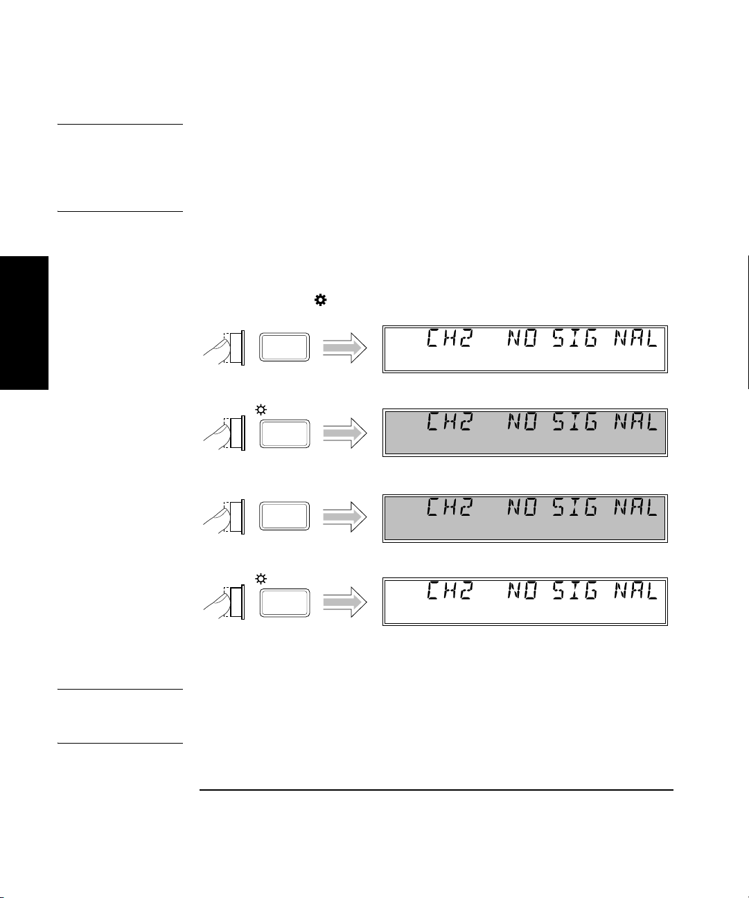
When you first turn the instrument on, the backlight for the LCD display
is always lit. You can toggle the backlight off and on by pressing the Shift
key and then the On/Off (Clear) key, as shown below.
1
Shift
Ch 2
Freq
Shift
On/Off
Clear
Shift
On/Off
Clear
Ch 2
Freq
Ch 2
Freq
Ch 2
Freq
Shift
NOTE If your instrument has the Battery option, you can extend the length of
time the instrument can operate from the batteries by turning off the
display backlight.
1-12 Operating and Programming Guide
Page 35
Chapter 1 Getting Started
Operating the Instrument
Using the Menu
The Agilent 53147A/148A/149A has one menu that you use to control a
number of the instrument’s features and functions.
Displaying the Menu
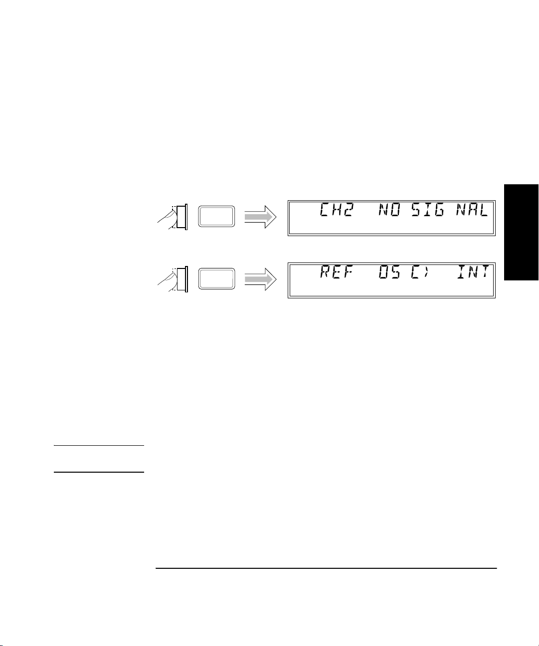
To display the Menu, press the Shift key and then the Menu (Reset/Local)
key, as shown below.
Ch 2
Shift
Menu
Reset/
Local
Freq
Shift
1
Navigating in the Menu and Changing Settings
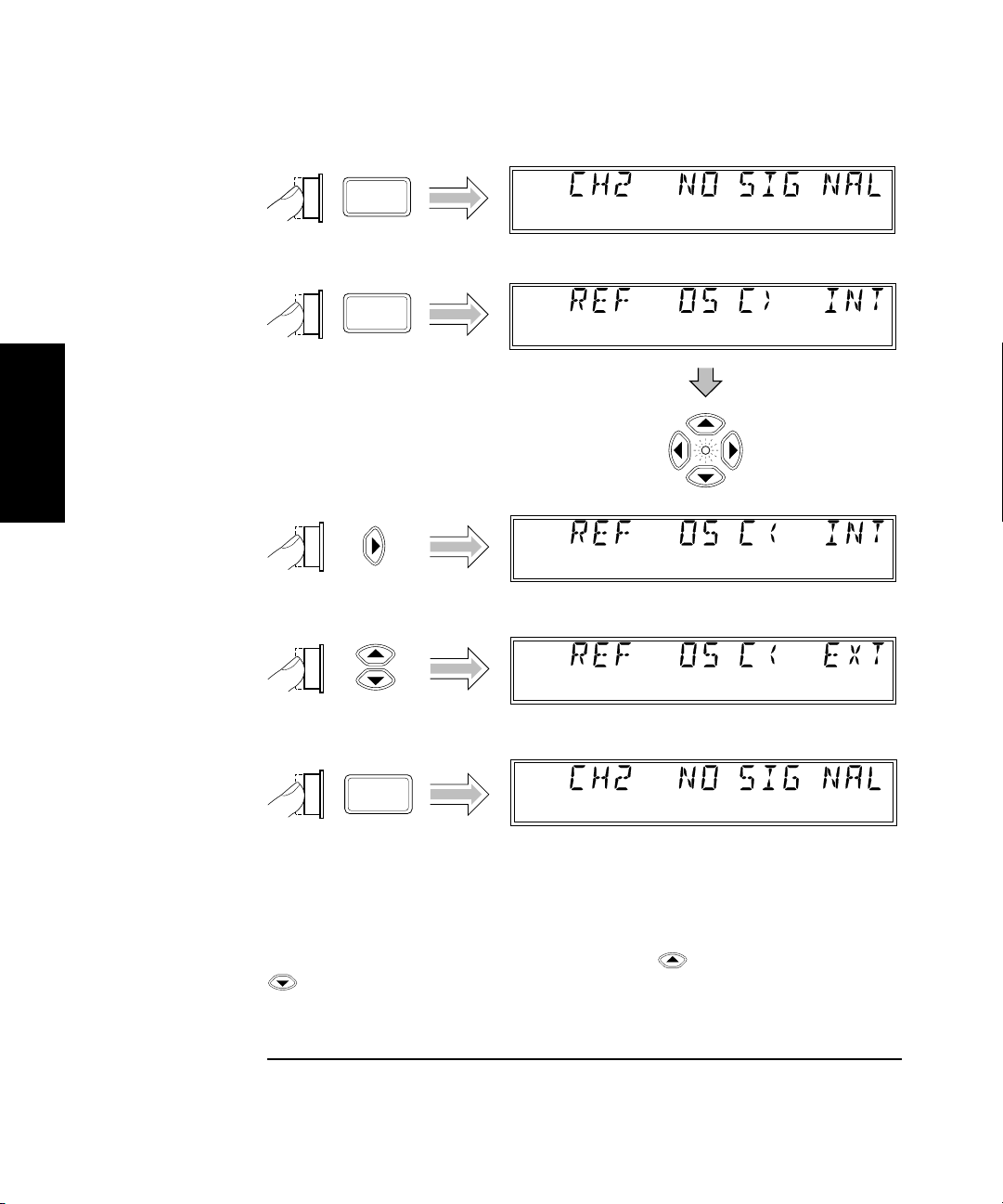
Use the Selection (arrow) keys to navigate to the setting you want to
change and then to actually make the changes. For example, the diagram
on the next page shows how to change the setting of the Reference
Oscillator from INTernal to EXTernal. (In this example, a reference signal
is applied to the External Reference connector, but no signal is applied to
the Channel 2 input.)
NOTE The instrument does not switch to EXTernal unless a suitable reference
signal is available at the External Reference connector.
Operating and Programming Guide 1-13
Page 36
Chapter 1 Getting Started
Operating the Instrument
Ch 2
Shift
Menu
Reset/
Local
Freq
Shift
1
Enter
Ch 2
Ext Ref
When you select the Menu, the indicator between the arrow keys flashes
to indicate that the arrow keys are now active. Since the Reference
Oscillator setting is the first one displayed when you invoke the Menu
(unless you’ve used the Menu to change another setting since you turned
the instrument on), you don’t have to use the (up-arrow) key or the
(down-arrow) key to get to it.
1-14 Operating and Programming Guide
Page 37
Chapter 1 Getting Started
Operating the Instrument
When you press the (right-arrow) key, the flashing annunciator ( )
changes direction, and the current setting for the Reference Oscillator
(INT [internal] or EXT [external]) flashes. This indicates that you can now
change this setting. Use either the up-arrow key or the down-arrow key to
change the setting.
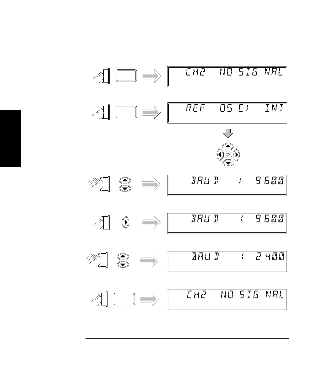
If there are more than two settings available for the currently selected
function, you can cycle through the available settings by repeatedly
pressing either the up-arrow key or the down-arrow key. For example,
to change the setting for the Baud rate for the serial port, use the
sequence on the next page.
Press either the Enter key or the left arrow key to accept the currently
displayed setting. The Enter key accepts the setting and exits the Menu;
the left arrow key accepts the setting but does not exit the Menu. Use the
left arrow key to accept a setting if you want to change additional menu
settings. The Clear key reverses an unaccepted setting change.
You navigate to and adjust the remaining settings available in the Menu
in the manner described above. The Menu also contains some items that
provide information only (no settings are required [or possible] for these),
such as Battery Voltage, Operation Hours, and information that identifies
the instrument (Agilent model number, firmware version number, serial
number, and installed option codes). These menu options and the ones
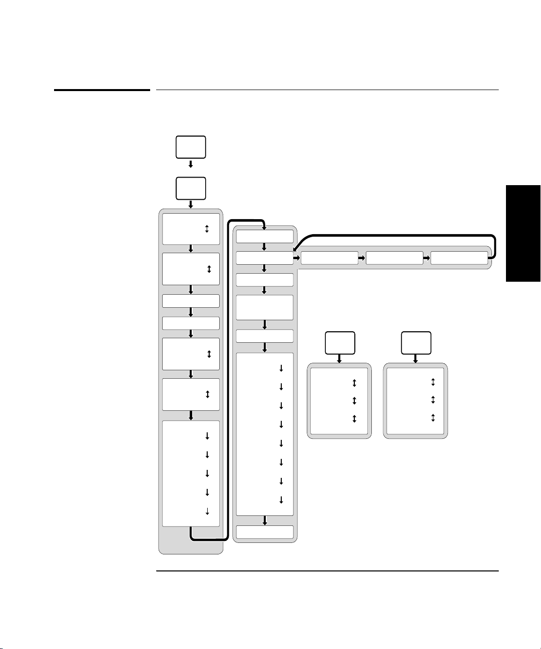
described below are shown in “The Front Panel Menus at a Glance” on
page 1-5.
There is also a menu item called Preset and one called Do Self Test. If you
press the Enter key while PRESET is displayed, all of the instrument’s
settings are returned to the factory-default settings. If you press Enter
while DO SELF TEST is displayed, the instrument repeats the tests that
are normally performed when the instrument is first turned on.
NOTE Remember to terminate each value you change in any of the menu options
by pressing the
any menu option while the Menu is displayed by pressing the
key or the
Enter key or the left arrow key. You can abort a change to
Reset/Local
Clear key. Both keys nullify any changes you made to the
current menu option, but they do not affect any changes to other menu
options. The
Reset/Local key does not.
Clear key terminates the current menu session, but the
1
Operating and Programming Guide 1-15
Page 38
Chapter 1 Getting Started
Operating the Instrument
Setting the Serial Port Baud Rate (Menu Example)
Ch 2
Shift
Menu
Reset/
Local
Freq
Shift
1
Ch 2
Enter
Freq
1-16 Operating and Programming Guide
Page 39
Chapter 1 Getting Started
Operating the Instrument
Selecting the Counter Input Channel
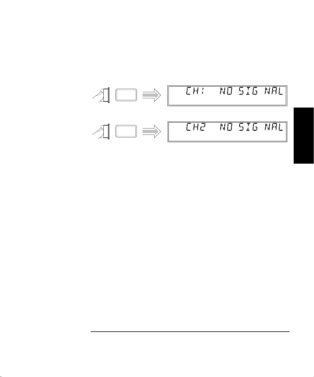
You can toggle between Counter Channels 1 and 2 by pressing the
Chan Select key.
Ch 1
Chan
Select
Chan
Select
Freq
Ch 2
Freq
1
Operating and Programming Guide 1-17
Page 40
Chapter 1 Getting Started
Operating the Instrument
Measuring Frequency
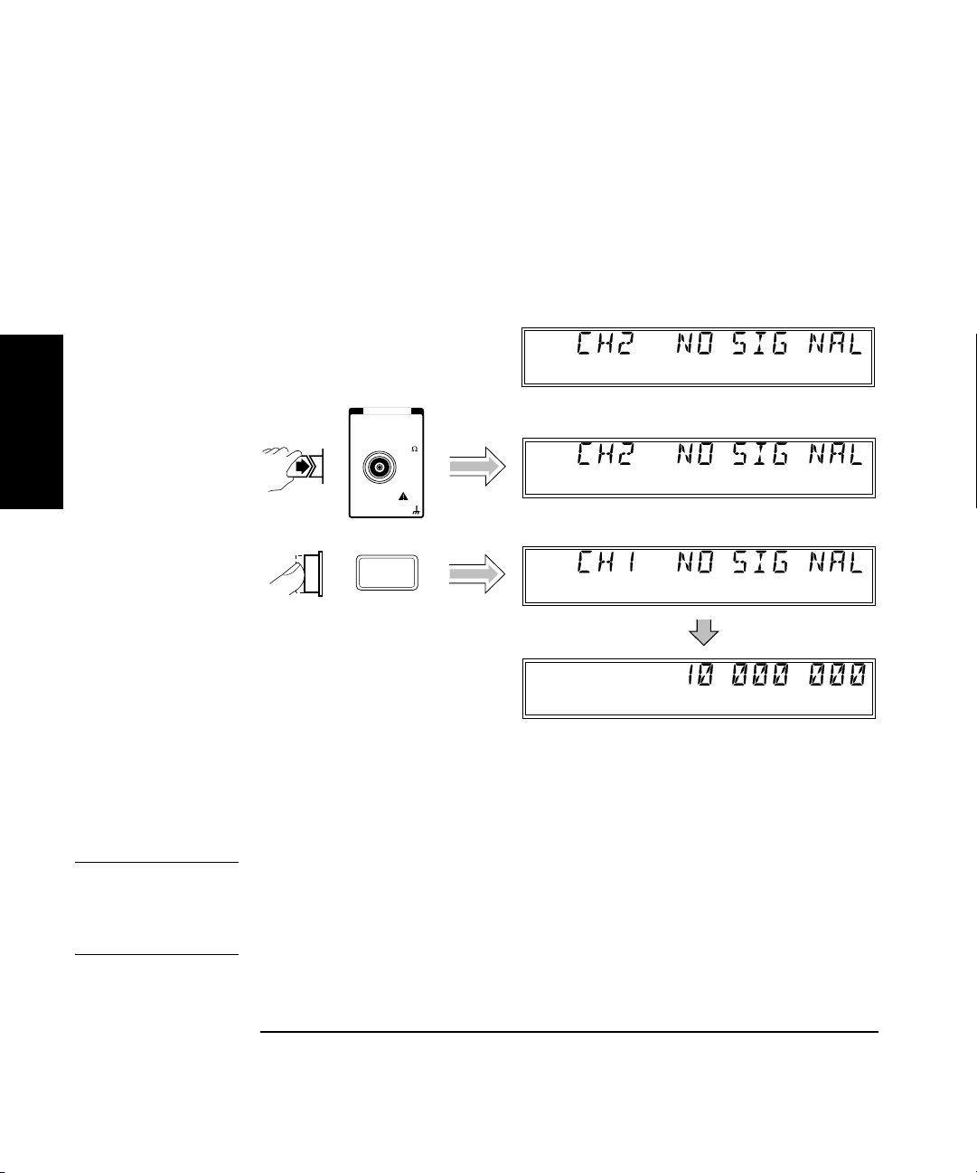
The following diagram shows the basic sequence to use to make a
frequency measurement using Channel 1. This example assumes that the
instrument is on and has completed the Self Test. For the purposes of this
example, use the 10 MHz reference output on the instrument’s rear panel
as a signal source for input to Counter Channel 1.
Ch 2
Freq
COUNTER
1
CHANNEL 1
10 Hz to 125 MHz
DAMAGE
+30 dBm
Chan
Select
1M
Ch 2
Freq
Ch 1
Freq
Ch 1
Freq
The same procedure applies to making a basic frequency measurement
on Channel 2. However, since Channel 2 is automatically selected when
you turn on the instrument, the channel-selection step is unnecessary
(unless you previously selected Channel 1).
CAUTION The Channel 2 input path circuits contain sensitive GaAs semiconductors.
To prevent damage to these components, always adhere to standard ESD
(Electro-Static Discharge) prevention procedures, and ensure that the
maximum power specification for this channel (+27 dBm) is not exceeded.
1-18 Operating and Programming Guide
Page 41

Chapter 1 Getting Started
Operating the Instrument
NOTES • The Counter displays CH2 NO SIGNAL or CH1 NO SIGNAL and shuts
down all unnecessary circuits when a signal of insufficient amplitude
(or no signal) is applied to the corresponding input. This lowers the
power consumption, and if the Battery option is installed, it extends the
length of time the instrument can operate from the batteries.
• When the frequency of a signal applied to the Channel 2 input exceeds
the maximum rated frequency for the Counter, it displays CH2 TOO HIGH.
• The DVM uses the same portion of the display to display voltage
measurements that the instrument uses to display frequency
measurements. Therefore, the DVM and the Counter cannot display
measurements simultaneously. Pressing the Display DVM key toggles
the upper portion of the display between the DVM and the Counter.
CAUTION The 2.9 mm Planar Crown* connector used for the Channel 2 input on the
Agilent 53149A must be handled with care to prevent damage and/or
contamination, especially since it acts as a wave guide as well as an
electrical connection. Observe the following precautions when handling
this connector:
1
1. If you remove the outer portion of the connector, do not touch the
exposed surfaces of either part of the connector with your bare skin or
any material that is not intended for cleaning this type of connector.
2. Avoid dropping or striking either portion of the connector.
If the connector becomes contaminated, it can be cleaned with isopropyl
alcohol and a lint-free cloth or other suitable cleaning implement.
*
Planar Crown® is a registered trademark of Weinschel Corp.
Operating and Programming Guide 1-19
Page 42
Chapter 1 Getting Started
Operating the Instrument
Measuring Relative Frequency
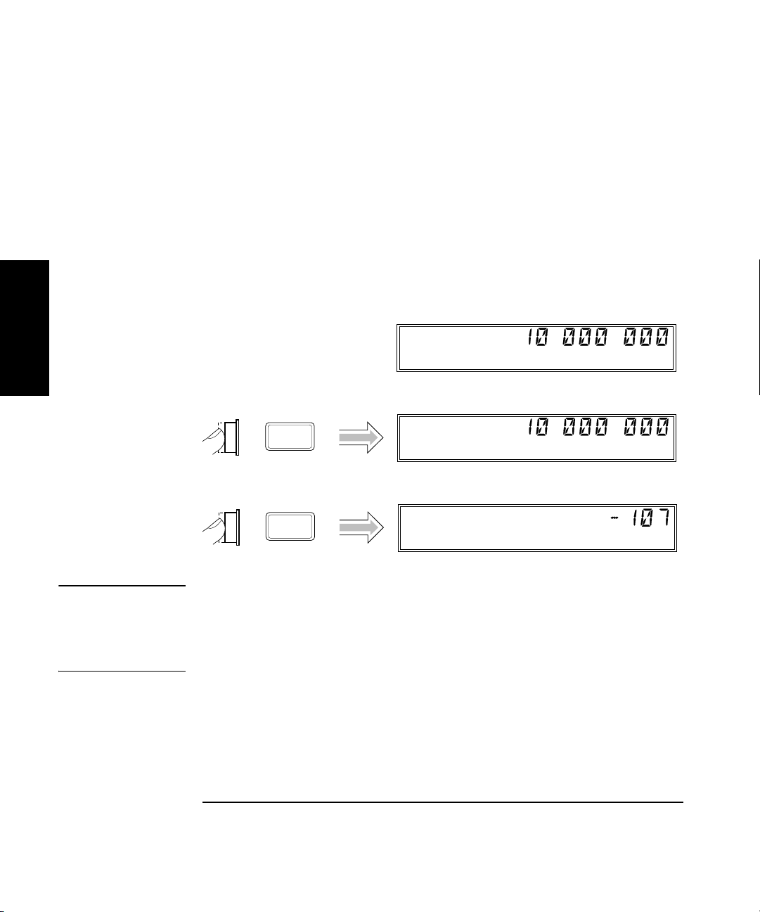
You can measure the difference in frequency from one measurement to
another (drift) using the Relative Frequency function. You do this by
pressing the Shift and Rel Freq (Offset On/Off) keys as shown in the
diagram below (this example assumes that a signal is currently applied
to Channel 1).
The Counter stores the current frequency reading when you press the
Rel Freq key. It then subtracts this value from all subsequent readings
and displays the difference until you press the Rel Freq key again.
1
Shift
Rel Freq
Ch 1
Freq
Ch 1
Freq
Ch 1
Rel Freq
NOTE If the input signal fluctuates, the value displayed varies as the Counter
continues to take measurements. You can vary the speed at which
measurements are taken by varying the settings for Rate and Resolution
(see “Setting the Measurement Rate” and “Setting the Resolution for
Frequency Measurements” on pages 1-29 and 1-31).
Shift
1-20 Operating and Programming Guide
Page 43

Chapter 1 Getting Started
Operating the Instrument
Offsetting a Frequency Measurement
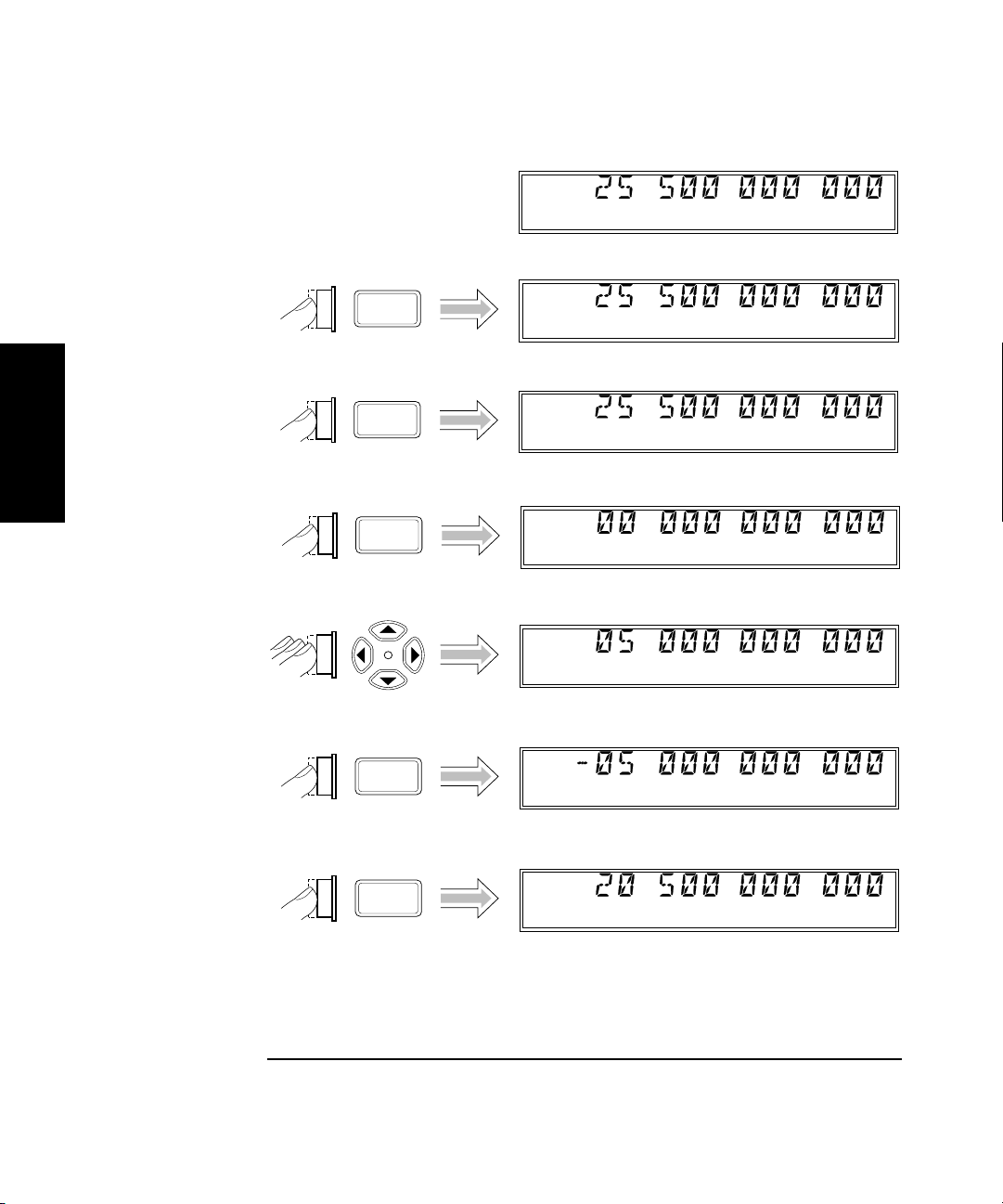
You can use the Frequency Offset (Freq Offset) function to add or subtract
a constant value to/from a frequency measurement. For example, you can
use an offset to compensate for a systematic error or to display the
difference in frequency between two signals.
NOTE The Frequency Offset and Relative Frequency functions can be used
simultaneously.
To display an offset frequency measurement, you need to set the value and
sign (+/–) of the offset and to turn the Frequency Offset function on. In the
diagram on the next page, the Frequency Offset function is enabled first,
and the offset value is then entered. However, the order doesn’t matter, so
you can also enter the offset value first, and then turn the offset function on.
NOTE When you are entering a value for Frequency Offset (or Power Offset),
you can use the Reset key to restore all of the displayed digits to zero.
These are the only two functions in which the Reset key has this effect.
1
Operating and Programming Guide 1-21
Page 44
Chapter 1 Getting Started
Operating the Instrument
Ch 2
Freq
Ch 2
Offset
On/Off
Shift
1
Freq
Offset
Resol
Freq
Offset
Ch 2
Freq
Offset
Freq
Offset
Shift
Freq
Offset
Rate
+/-
Enter
Freq
Offset
Ch 2
Freq
Offset
1-22 Operating and Programming Guide
Page 45

Chapter 1 Getting Started
Operating the Instrument
Measuring Power
The Agilent 53147A/148A/149A can measure signal power (the power and
frequency ranges for power measurement are dependent on the powersensor model used). To measure power, you must first set the Power Meter
for the power-meter sensor (head) that you intend to use.
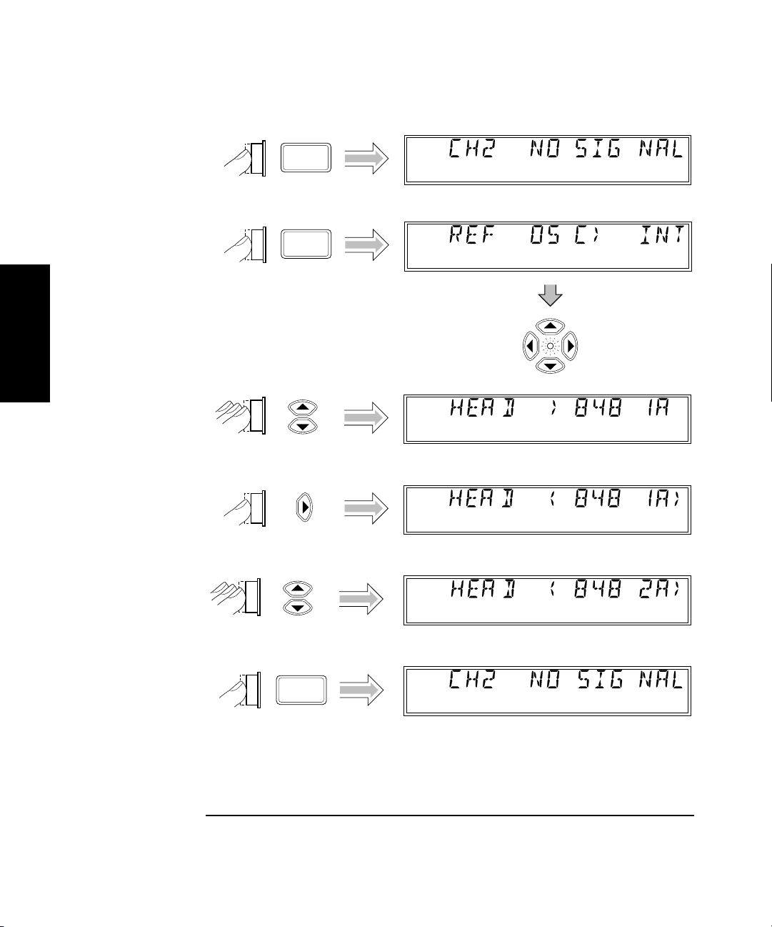
Selecting a Power Meter Head (Sensor) Model
The example procedure in the following diagram shows how to select the
model number of the power-meter head (sensor). This procedure assumes
that the Power Meter is currently set to use a model 8481A power sensor
and that you intend to use a model 8482A power sensor.
NOTE When you select a power head (sensor), you are implementing a
preconfigured calibration table for that head. There are five preconfigured
tables (for head models 8481A, 8481D, 8482A, 8485A, and 8487A) and
three custom calibration tables (CUST 1, CUST 2, and CUST 3). You can
modify the frequency/calibration-factor values in any of the data points for
any power head, add data points to any configuration table (up to a
maximum of 100 data points per table), and input data to build new
calibration tables by selecting CUST 1, CUST 2, and/or CUST 3. Complete
instructions for modifying and adding calibration tables are provided in
“Modifying and Adding Calibration Factor Tables” on page 2-27.
1
Operating and Programming Guide 1-23
Page 46
Chapter 1 Getting Started
Operating the Instrument
Ch 2
Shift
Menu
Reset/
Local
Freq
Shift
1
Ch 2
Enter
Freq
1-24 Operating and Programming Guide
Page 47
Chapter 1 Getting Started
Operating the Instrument
Measuring Power
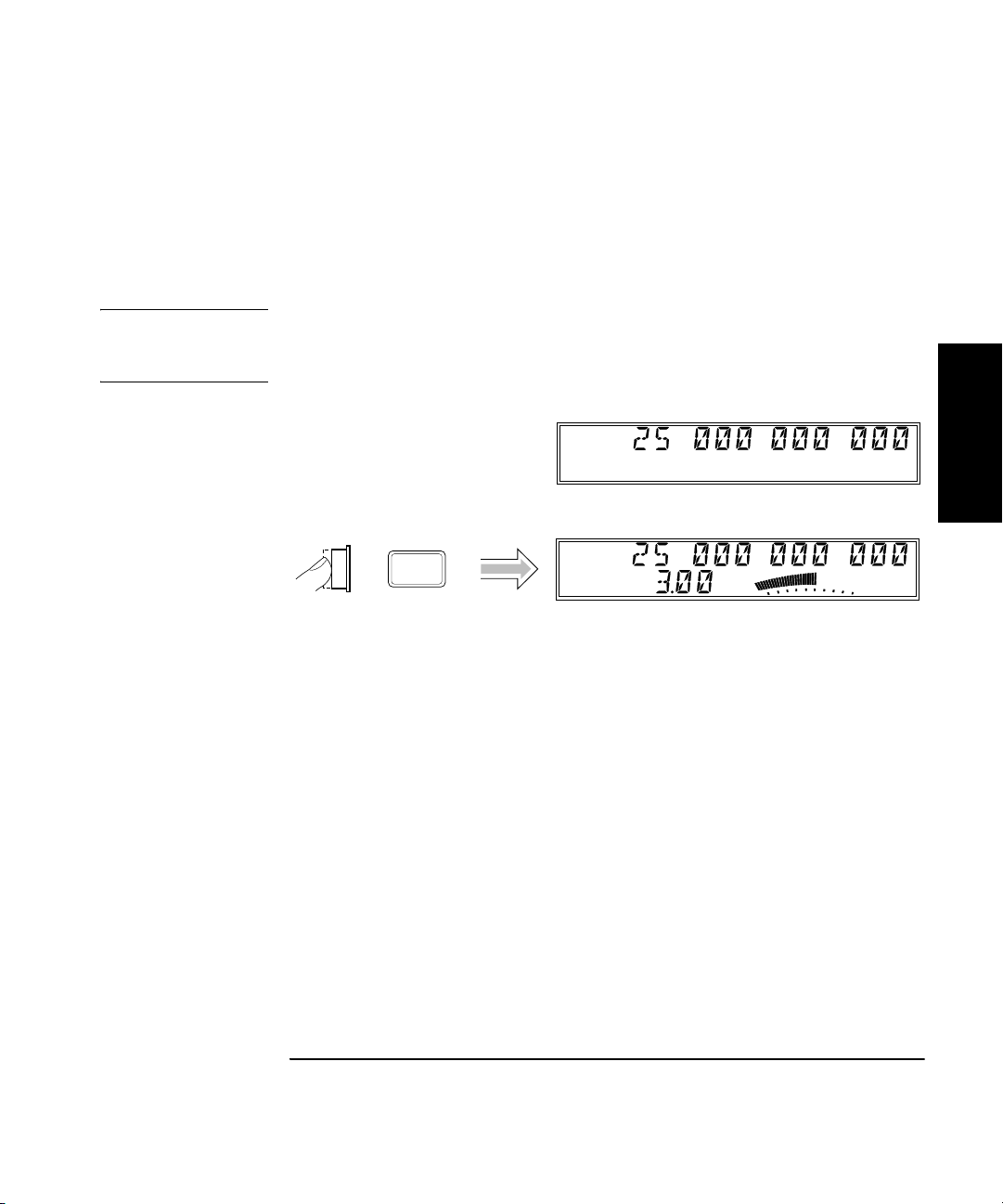
The procedure for measuring power that is illustrated in the following
diagram assumes that the power-sensor head being used has been
selected in the instrument’s menu and that the signal to be measured is
connected to the head.
NOTE When the power of a signal applied to the Power Meter Input connector
exceeds the maximum rated power for the Power Meter head, the Power
Meter displays HI.
Display
Power
Ch 2
Freq
Freq
Pwr
1
Ch 2
dBm
Operating and Programming Guide 1-25
Page 48
Chapter 1 Getting Started
Operating the Instrument
Selecting the Unit of Measurement for Power
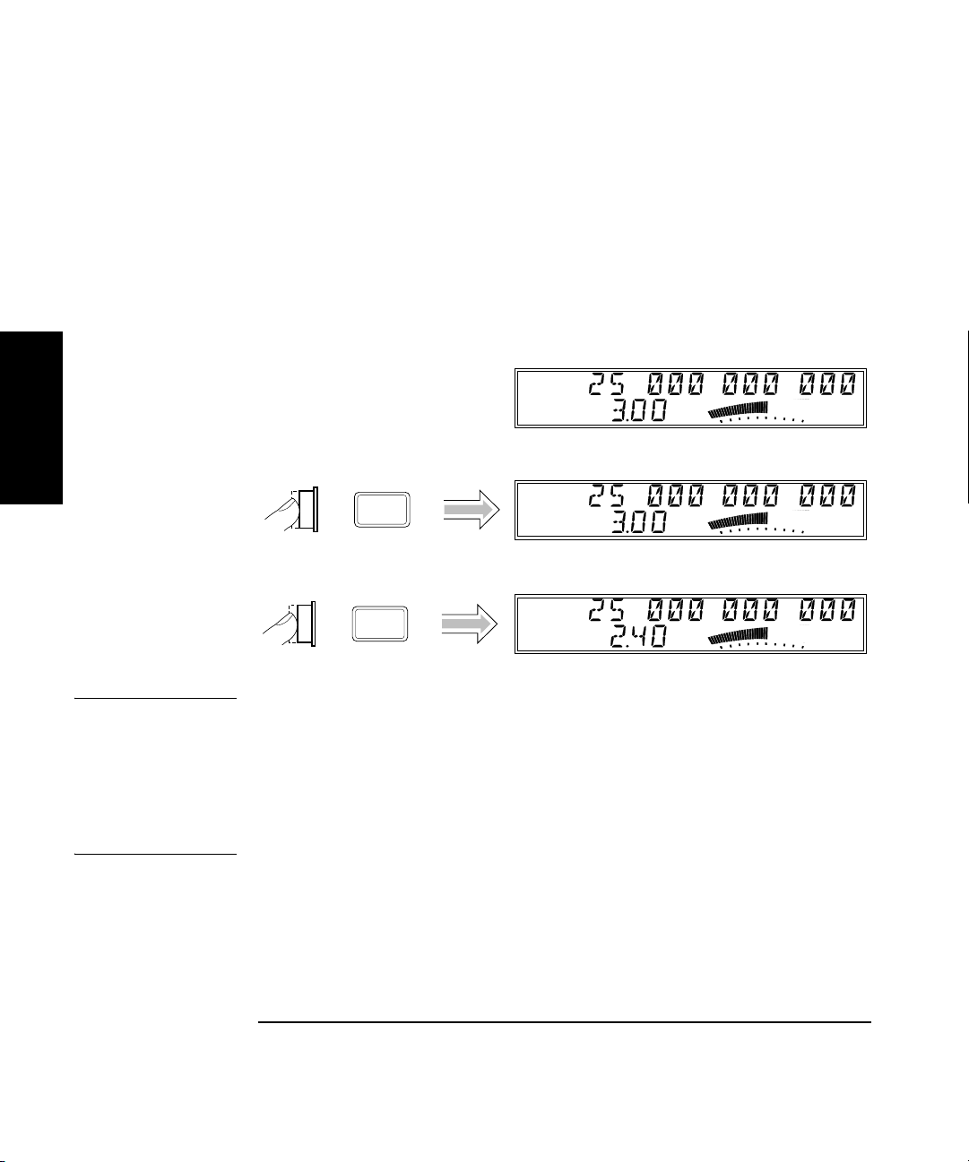
The instrument’s power meter can display values in either of two sets
of units of measurement—dB and dBm or Watts, mW, µW, and nW
(the power meter automatically selects the most appropriate unit of
measurement when Watts is selected). Use the procedure in the following
diagram to select the unit of measurement for power (this procedure
assumes that a signal is currently applied to the power meter and that
power is being displayed):
Ch 2
Freq
1
Shift
Pwr
Ch 2
Freq
Pwr
dBm
dBm
Shift
dBm/W
Display
Power
Ch 2
Freq
Pwr
mW
NOTE If a signal having an amplitude that exceeds the Power Meter
specifications is applied, and power measurement is enabled, the
annunciators for the power reading display “HI” to indicate that the
signal’s amplitude exceeds the specification. If a signal having an
amplitude below the minimum specification is applied, the power
annunciators display “LO” to indicate that the signal level is too low to
be measured by this Power Meter.
1-26 Operating and Programming Guide
Page 49
Chapter 1 Getting Started
Operating the Instrument
Measuring Relative Power
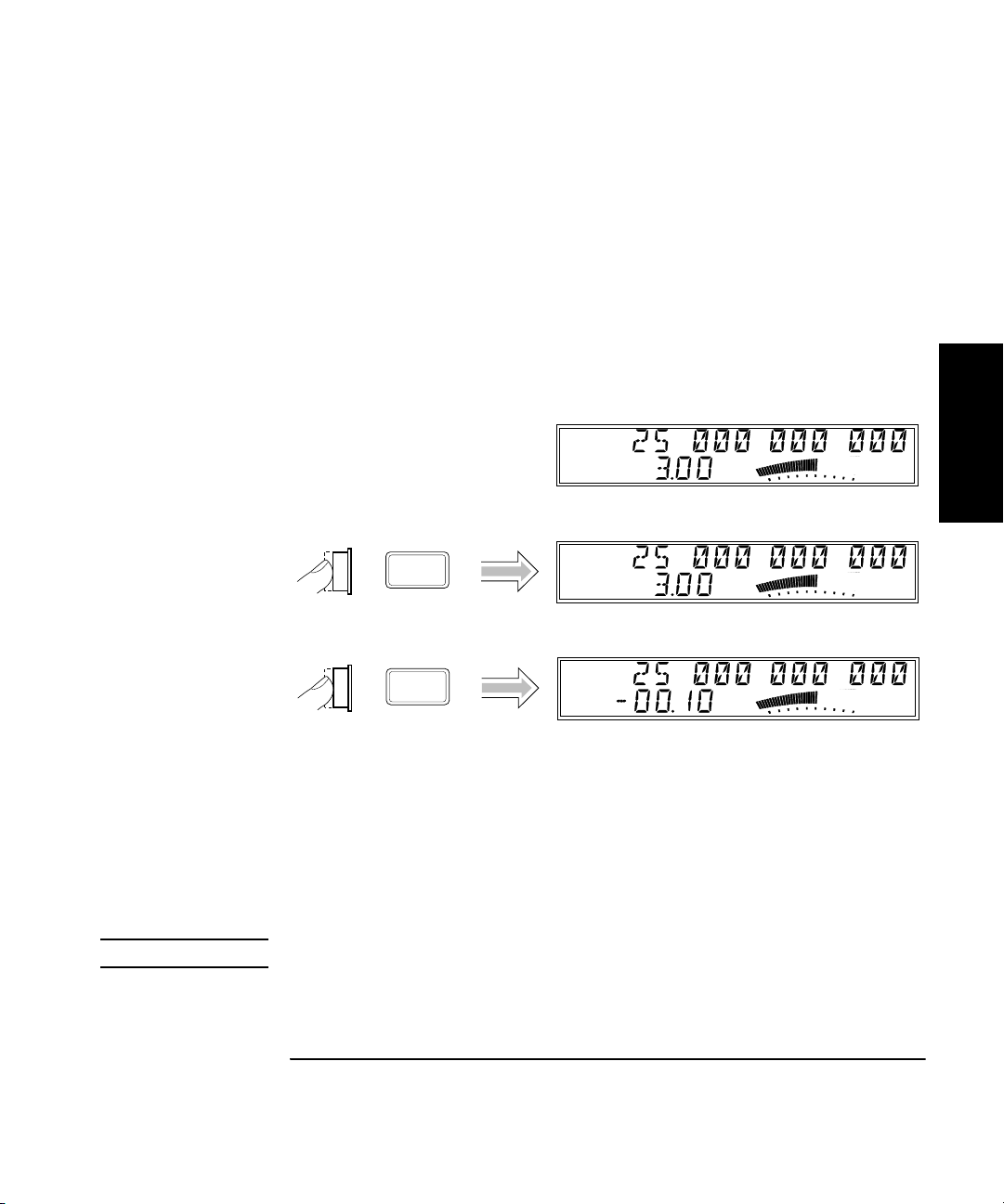
You can measure the difference in power from one measurement to
another (drift) using the Relative Power function. You do this by pressing
the Shift and Rel Pwr (Offset On/Off) keys, as shown in the diagram below
(this example assumes that a signal is currently applied to the Power
Meter input connector).
The Power Meter stores the current power reading when you press the
Rel Pwr key. It then subtracts this value from all subsequent readings and
displays the difference until you press the Rel Pwr key again.
Ch 2
Shift
Rel Pwr
Offset
On/Off
Freq
Pwr
Ch 2
Freq
Pwr
Ch 2
Freq
Rel Pwr
dBm
dBm
Shift
dB
Offsetting a Power Measurement
You can use the Power Offset (Pwr Offset) function to add or subtract a
constant value to/from a power measurement. For example, you can use
an offset to compensate for a systematic error or to display the difference
in power between two signals.
NOTE The Power Offset and Relative Power functions can be used simultaneously.
1
Operating and Programming Guide 1-27
Page 50
Chapter 1 Getting Started
Operating the Instrument
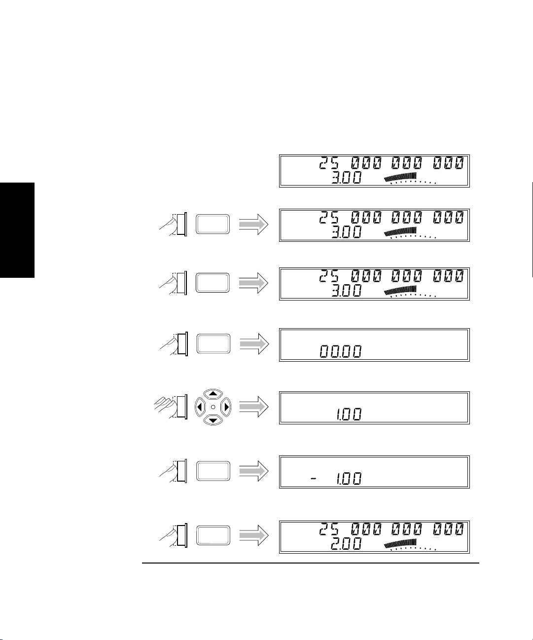
To display an offset power measurement, you need to set the value and
sign (+/–) of the offset and to turn the Power Offset function on. In the
following diagram, the Power Offset function is enabled first, and the
offset value is then entered. However, the order doesn’t matter, so you can
also enter the offset value first, and then turn the offset function on.
Ch 2
Freq
Pwr
dBm
Rel Pwr
Offset
1
On/Off
Shift
Pwr
Offset
Avg
+/-
Ch 2
Freq
Pwr
Offset
Ch 2
Freq
Pwr
Offset
Pwr
Offset
Pwr
Offset
Pwr
Offset
dB
dB
Shift
dB
dB
dB
Ch 2
Enter
Freq
Pwr
Offset
dB
1-28 Operating and Programming Guide
Page 51
Chapter 1 Getting Started
Operating the Instrument
Setting the Measurement Rate
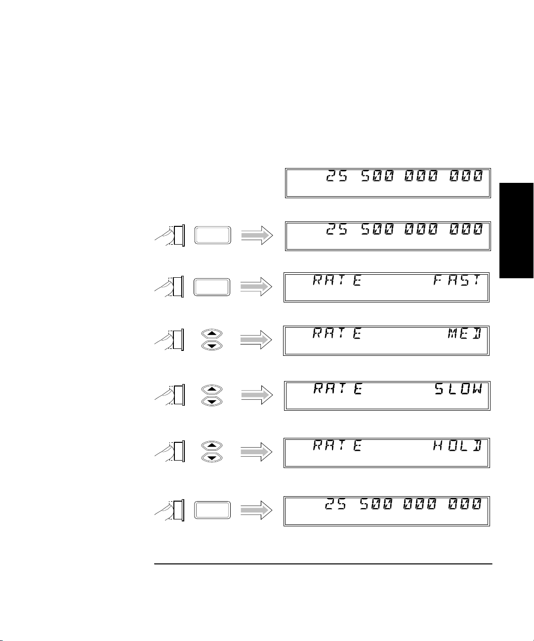
The measurement rate determines how frequently the instrument
takes measurements (frequency, power, and/or voltage). You can set
the measurement rate to FAST, MED (medium), SLOW, or HOLD
(single measurement taken each time you press the Reset/Local key).
Ch 2
Freq
Shift
Rate
+/-
Enter
Ch 2
Freq
Ch 2
Freq
1
Hold
Operating and Programming Guide 1-29
Page 52
Chapter 1 Getting Started
Operating the Instrument
Setting the Number of Averages
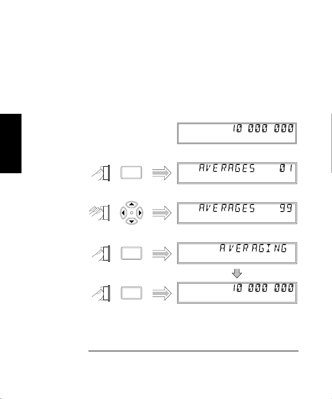
You can set the number of frequency, power, and/or voltage measurements
the instrument takes and averages before displaying the result. The default
setting is one (no averages are performed), and the maximum setting is
99. Note that the tens position (10 through 90) and the units position
(0 through 9) are adjusted separately, and that you cannot set the number
of averages to zero.
Ch 1
Freq
1
Pwr
Offset
Avg
Ch 1
Enter
Enter
Freq
Avg On
Ch 1
Freq
Avg On
1-30 Operating and Programming Guide
Page 53

Chapter 1 Getting Started
Operating the Instrument
NOTE For most of the instrument’s settings, when you continue to press either
the up-arrow or the down-arrow key when you reach the end of the
available settings, the value for the setting “rolls over” to the value at the
opposite end of the range. For example, if the GPIB address is set to 31,
and you press the up-arrow key, the value changes to one.
However, when you adjust the value in the units position for the number
of measurements to be averaged, rollover does not occur. If you press the
up-arrow when the value in the tens position is zero and the value in the
units position is nine, or if you press the down-arrow when the value in
the tens position is zero and the value in the units position is one, there
is no change. If the value in the units position could roll over (in either
direction), it would allow you to set a value of zero for the number of averages.
Since at least one measurement must be taken, zero is an illegal value.
NOTE When the resolution setting is high (e.g., 1 Hz), and a large number of
averages is selected, it takes a considerable amount of time for the
instrument to take the measurements, compute the averages, and display
a reading. As a result, the rate at which the display is updated is
considerably slower than at small numbers of averages and lower
resolution settings. For example, when the resolution is set to 1 Hz,
and the number of averages is set to 60, a new reading is displayed every
60 seconds (approximately).
1
Setting the Resolution for Frequency Measurements
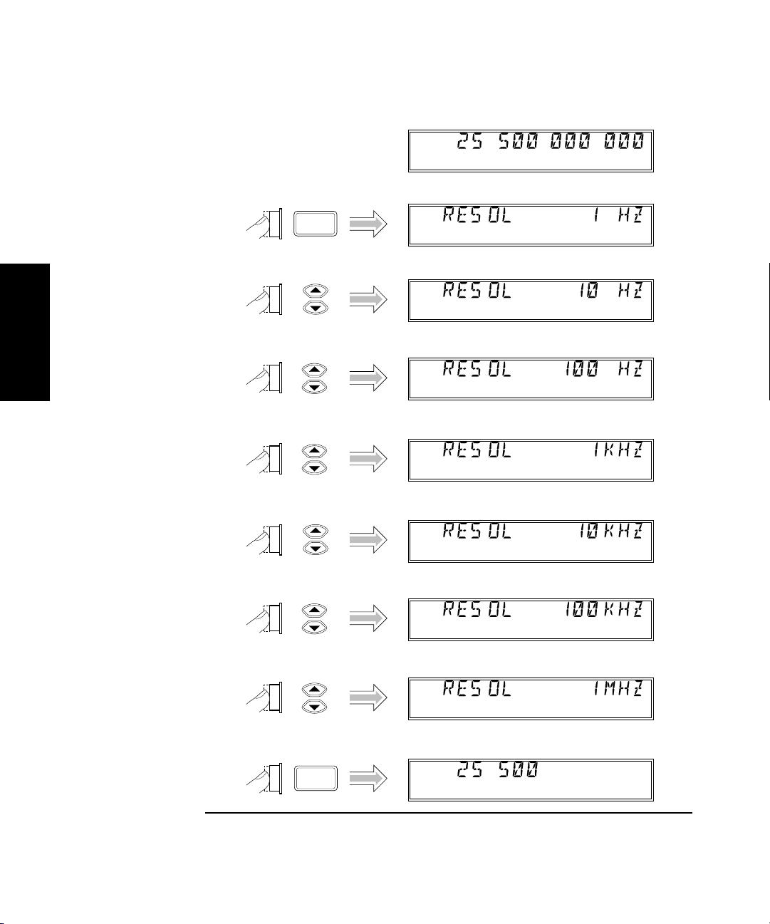
Since less time is required to complete each measurement as the
resolution of the measurements is reduced, the resolution setting affects
the rate at which measurements are taken and displayed, as well as the
number of digits displayed for the measurements. As a result, the rate at
which the Gate indicator flashes changes when you change the resolution.
As shown in the procedure in the diagram on the next page, the available
resolution settings are 1 Hz (the default setting), 10 Hz, 100 Hz, 1 kHz,
10 kHz, 100 kHz, and 1 MHz.
Operating and Programming Guide 1-31
Page 54
Chapter 1 Getting Started
Operating the Instrument
Ch 2
Freq
Freq
Offset
Resol
1
Ch 2
Enter
Freq
1-32 Operating and Programming Guide
Page 55
Chapter 1 Getting Started
Operating the Instrument
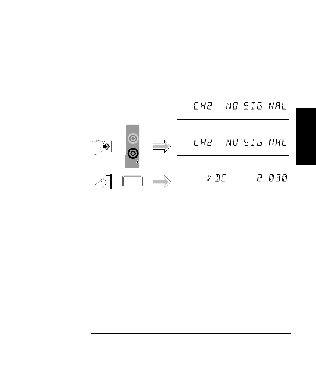
Measuring Voltage
To measure voltage, press the Display DVM key, connect the red DVM test
lead to the red + DVM connector, connect the black DVM test lead to the
black – DVM connector, and touch the red and black test prods to the
source of the voltage you want to measure.
Ch 2
Freq
DVM
+
Ch 2
–
DAMAGE
±60 VDC
Display
DVM
Freq
1
If the positive test lead is applied to a positive voltage source, and the
negative lead is applied to a return for that source, the meter indicates the
positive value (+) of the voltage. If the positive test lead is applied to a
negative voltage source, and the negative lead is applied to a return for
that source, the meter indicates the negative value (–) of the voltage.
NOTE The DVM automatically selects the appropriate voltage range to display
the measurement with maximum accuracy, and it automatically
determines and displays the polarity of the voltage measured.
CAUTION The 53147A/148A/149A DVM can measure voltages up to ± 50VDC.
Applying voltages outside of the ± 60VDC range to the DVM inputs can
damage the DVM.
Operating and Programming Guide 1-33
Page 56

Chapter 1 Getting Started
Operating the Instrument
1
1-34 Operating and Programming Guide
Page 57

2
Operating Your Instrument
Page 58

Chapter 2 Operating Your Instrument
Introduction
Introduction
This chapter contains information and usage procedures for the frontpanel keys, operating functions, and menus of the Agilent 53147A,
53148A, and 53149A.
Chapter Summary
• How this Instrument Works for You pg. 2-3
• Summary of the Measurement Sequence pg. 2-4
• Using the Selection Keys pg. 2-5
• Numeric Entry pg. 2-6
• Changing States pg. 2-6
• Acknowledging Messages pg. 2-8
• Using the Clear and Reset/Local Keys pg. 2-8
2
• Other Function Selection Keys pg. 2-9
• Measuring Frequency pg. 2-11
• Setting the Resolution and Measurement Rate pg. 2-13
• Setting the Number of Averages pg. 2-16
• Measuring Relative Frequency pg. 2-19
• Offsetting a Frequency Measurement pg. 2-20
• Measuring Power pg. 2-23
• Measuring Relative Power pg. 2-38
• Offsetting a Power Measurement pg. 2-39
• Measuring Voltage pg. 2-42
• Using the Menu pg. 2-43
2-2 Operating and Programming Guide
Page 59

Chapter 2 Operating Your Instrument
How this Instrument Works for You
How this Instrument Works for You
The following is a list of some of the key things the instrument does
for you.
• Presets the menus to default states and values at power-up.
• The instrument’s Menu key and other front-panel keys allow you to
select such things as the timebase source, the GPIB address, and the
RS-232 serial-port baud rate. The instrument also allows you to store
your selections in non-volatile memory; thus, these settings are not lost
when power has been off or after a remote-interface reset.
• Automatically displays measurement(s) when you have selected a
measurement function.
• Accepts your entry for a menu item when you press the Enter key.
You must press the Enter key to complete each setting and/or selection.
• Saves user configuration settings.
Operating and Programming Guide 2-3
2
Page 60

Chapter 2 Operating Your Instrument
Summary of the Measurement Sequence
Summary of the Measurement Sequence
1. Connect the power cord to the instrument and to an appropriate power
source (or, if the instrument has the Battery option, turn on the
Battery Power switch), and then press and release the POWER button
on the front panel.
NOTE The internal Reference Oscillator receives power whenever the power cord
is connected to a power source. Therefore, if the instrument has just been
connected to a power source, the frequency of the reference signal may
drift until the oscillator stabilizes. Specifications for the stability of the
standard internal timebase and the optional Oven Timebase are provided
in Chapter 3.
2. Connect the input signal to the appropriate input connector (Counter
Channel 1, Counter Channel 2, Power Meter input, or DVM input).
3. Connect an external reference signal to the External Reference
2
connector on the back panel (if desired).
4. Press the Chan Select key, the Display Power key, and/or the Display
DVM key to select the measurement function (if necessary).
5. Press the Freq Offset key and/or the Power Meter Offset On/Off key(s)
to enable offset measurements (if desired), and then use the Freq
Offset (Shift + Resol) and/or Pwr Offset (Shift + Avg) keys to enter the
offset values.
6. Use the Resol, Rate (Shift + +/–), and Avg keys to configure the display.
7. Use the Menu (Shift + Reset/Local) key to set the reference-oscillator
source, to select the Channel 1 low-pass filter, to configure the
Counter’s response to frequency modulation, to select a Power Meter
head, and/or to select a previously saved set of user settings.
8. If you intend to operate the instrument remotely using the GPIB,
use the Menu (Shift + Reset/Local) key to set the GPIB address.
9. If you intend to operate the instrument remotely using the serial
interface, use the Menu (Shift + Reset/Local) key to adjust the serial
port Baud rate.
2-4 Operating and Programming Guide
Page 61
Chapter 2 Operating Your Instrument
Enter
Using the Selection Keys
Using the Selection Keys
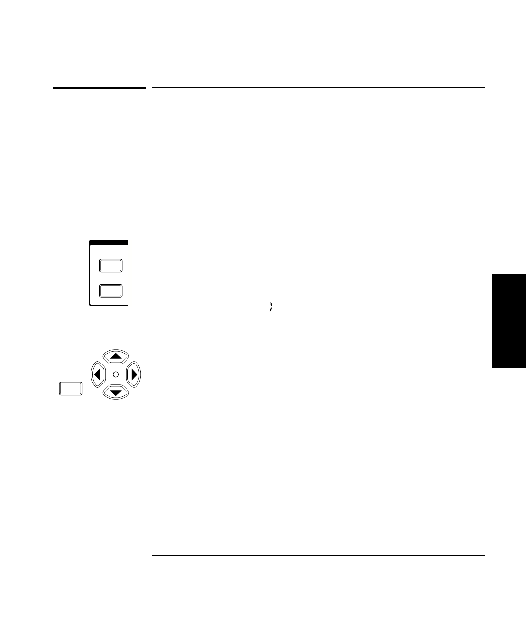
There are six Selection keys—four “arrow” keys, the Enter key, and the
sign (+/–) key. The functions of the arrow keys depend on the instrument’s
operating mode (i.e., sequencing through choices in the Menu, numeric
entry, state change, etc.). This section describes how the Selection keys
function in these different operating modes.
Sequencing Through the Menu
To access the Menu, press the Shift key, and then press the Menu
(Reset/Local) key.
Menu
Reset/
Local
• Press the up- or down-arrow key to go forward to the next menu
function or back to the previous menu function. Pressing either of these
keys repeatedly cycles through the list of menu functions.
Shift
• Press the right-arrow key to select a function. When you do this, the
flashing annunciator ( ) changes direction and the current setting
flashes to indicate that you can now use the up- and down-arrow keys
to cycle through the available settings.
• Press the up- or down-arrow key to move through the list of available
settings for a function. Pressing either of these keys repeatedly cycles
through the list of settings.
• Press the Sign (+/–) key to change the sign of numeric values.
• Press the Enter key to accept the currently displayed setting and exit
the Menu.
NOTE In most cases, when you reach the top or bottom of a list of settings, or the
left or right end of a numerical field, the focus rolls over to the opposite
end of the list of settings, or wraps around to the opposite end of the
numeric field. In some situations, however, this does not occur, because if
it did, you could choose an illegal setting. For these settings, you have to
use the opposite button to cycle back through the values or settings.
2
Operating and Programming Guide 2-5
Page 62
Chapter 2 Operating Your Instrument
Enter
Using the Selection Keys
Numeric Entry
Several menu functions, and several functions that have dedicated keys
on the front panel, require you to enter numeric values.
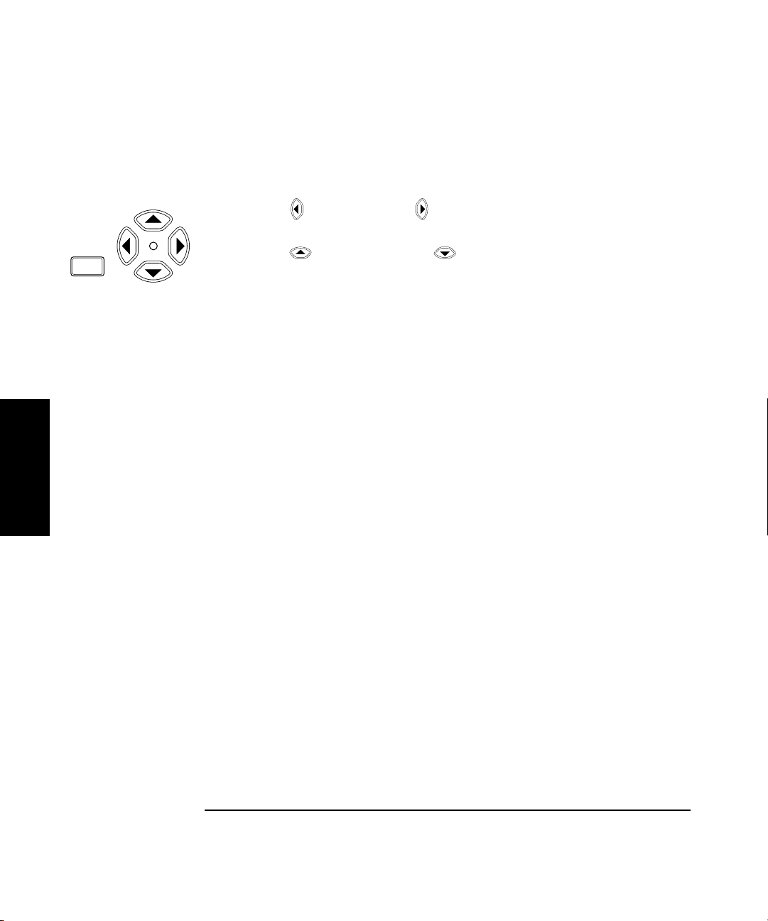
• Press the (left-arrow) and (right-arrow) keys to move left and
right to select adjustable digits (the selected digit flashes).
• Press the (up-arrow) and/or (down-arrow) key to increment and
decrement the selected (flashing) digit of the displayed value (see note
on previous page).
• Press the Sign (+/–) key to change the sign of the numeric value.
• Press the Enter key to complete a numeric entry. (If you change the
value of a numeric entry, but you forget to press the Enter key, the
value of the entry is not changed.)
Changing States
Several menu functions, and several functions that have dedicated keys
on the front panel, require you to choose from a list of available states.
2
These functions and the states you can choose for each of them are:
• Reference Oscillator (REF OSC)
– Internal (INT)
–External (EXT)
• Serial Port Baud Rate (BAUD)
– 1200
– 2400
– 4800
– 9600
– 14400
– 19200
• Frequency Modulation (FM)
– Automatic (AUTO)
–Off (OFF)
2-6 Operating and Programming Guide
Page 63

Chapter 2 Operating Your Instrument
Using the Selection Keys
• Channel 1 Low-Pass Filter (CH1 LPF)
–On (ON)
–Off (OFF)
• Measurement Rate (Rate key)
–Fast (FAS T)
–Medium (MED)
–Slow (SLOW)
–Hold (HOLD)
• Resolution (Resol key)
– 1 Hz, 10 Hz, 100 Hz, 1 kHz, 10 kHz, 100 kHz, 1 MHz
Use the Selection keys as described below to change the state of these
functions:
• When the annunciator ( ) in the display flashes, press the right-arrow
key to move the focus from the displayed menu function (or frontpanel-key function) to the setting for that function.
2
• Press the up- or down-arrow key to cycle through the available choices.
Press the Enter key to complete the setting. (If you change the setting of
a function, but you forget to press the Enter key, the setting of the function
is not changed.)
NOTE The Sign key has no function and is ignored in menu selections and
front-panel functions that have state-change selections only.
Operating and Programming Guide 2-7
Page 64
Chapter 2 Operating Your Instrument
Reset/
Local
Freq
Offset
On/Off
Clear
Resol
Shift
Menu
Using the Clear and Reset/Local Keys
Using the Clear and Reset/Local Keys
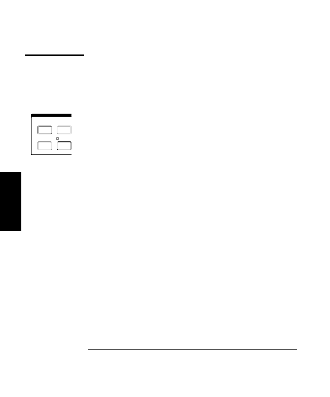
The Clear and Reset/Local keys have similar functions in the Menu and
in other front-panel-key function settings, but their effects vary with the
instrument’s state and condition. In general, the Reset/Local key restores
the setting that was in effect when you entered the Menu or frontpanel-key function, but it does not close the Menu or the function-setting
display. The Clear key also restores the previous setting, but it closes the
Menu or the front-panel-key function-setting display at the same time.
If you press the Reset/Local key while the instrument is taking
measurements, it resets the current operation and forces the instrument
to reacquire and re-measure the signal.
Pressing the Reset/Local key while the instrument is in Remote Mode
forces the instrument into Local Mode and enables all of the front-panel
controls.
2
Acknowledging Messages
When a message is displayed, press the Reset/Local key, the Clear key,
or the Enter key (after reading the message) to acknowledge it and erase
it from the display.
2-8 Operating and Programming Guide
Page 65
Chapter 2 Operating Your Instrument
MODIFY
Cal
Factor
Freq
Offset
On/Off Rate
Freq
Pwr
Offset
Avg
+/-+/-Clear
Resol
Enter
MO
Cal
Factor
Freq
Offset
On/Off Rate
Freq
+/-+/-Clear
Resol
COUNTER
Offset
On/Off
Rel Freq
Other Function Selection Keys
Other Function Selection Keys
There are several functions that you access directly from front-panel keys
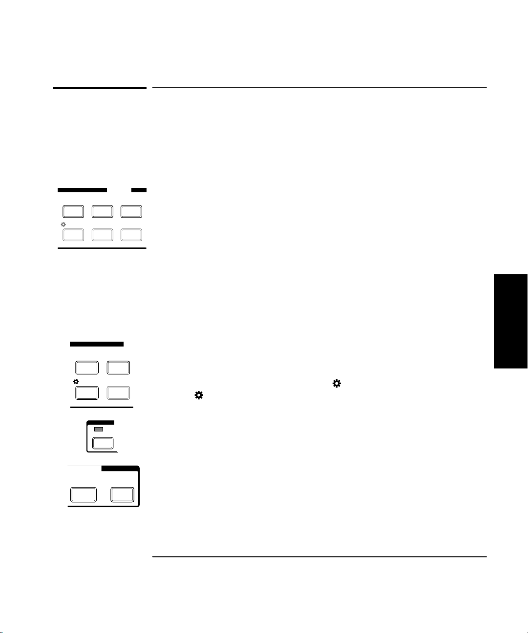
(not from within the Menu). These functions, which are all in the MODIFY
section of the front panel, are:
• Display Resolution (Resol key)
• Frequency Offset (Freq Offset — Shift + Resol key)
• Frequency (Freq key)
• Calibration Factor (Cal Factor — Shift + Freq key)
• Measurement Rate (Rate — Shift + +/– key)
• Number of Averages (Avg key)
• Power Offset (Pwr Offset — Shift + Avg key)
Use the Selection keys in the manner described earlier in this chapter
(see “Numeric Entry” and “Changing States”) to adjust the settings for
these functions. Detailed procedures for using the Resol, Freq Offset,
Freq, Cal Factor, Rate, and Avg keys are provided later in this chapter.
2
Chan
Select
Gate
There are also a number of functions that are toggled between states
(no selections or numerical-entry fields are displayed) using named
front-panel keys. These are:
• Display backlight on or off (MODIFY: On/Off). Press Shift, and then
press On/Off (the Clear key in the MODIFY section of the front panel).
C
• Frequency channel selection (COUNTER: Chan Select). Press the Chan
Select key in the COUNTER section of the front panel to toggle
between the two Counter input channels.
• Frequency offset measurement (COUNTER: Offset On/Off). Press the
Offset On/Off key in the COUNTER section of the front panel to turn
the frequency offset function on or off.
• Relative frequency measurement (COUNTER: Rel Freq). Press the
Rel Freq key in the COUNTER section of the front panel to measure
the difference in frequency between the current measurement and the
measurement taken at the time you pressed the Rel Freq key (drift).
Operating and Programming Guide 2-9
Page 66
Chapter 2 Operating Your Instrument
POWER METER
Display
Power
dBm/W
Store
Cal
Zero
Offset
On/Off
Rel Pwr
–
DAMAGE
±60 VDC
Display
DVM
Other Function Selection Keys
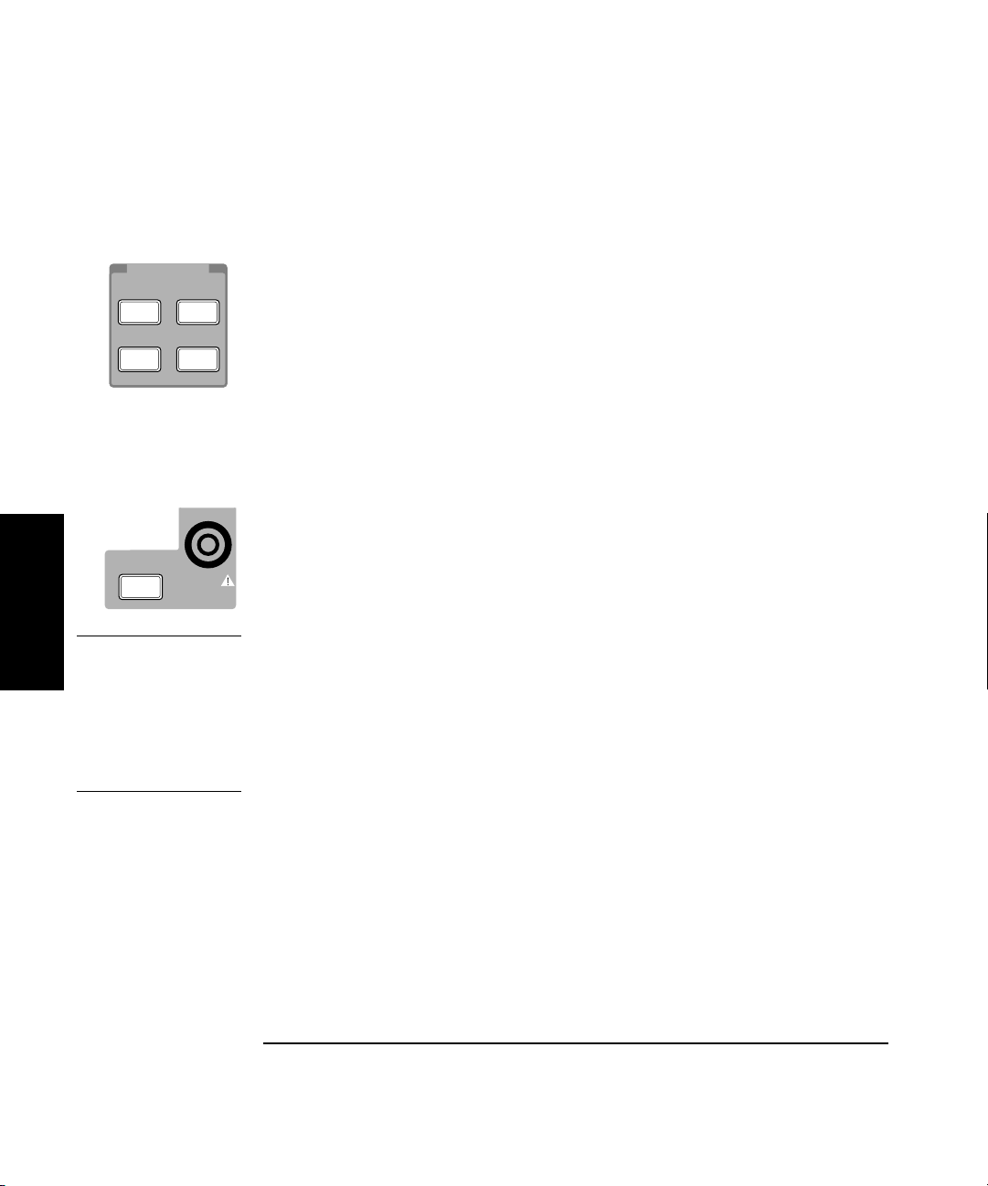
• Display power measurement (POWER METER: Display Power).
Press the Display Power key in the POWER METER section of the front
panel to turn the power measurement function on and off.
• Power offset (POWER METER: Offset On/Off). To turn the power offset
function on or off, press the Offset On/Off key in the POWER METER
section of the front panel (Display Power must be selected).
• Relative power measurement (POWER METER: Rel Pwr — Shift +
Offset On/Off). Press Shift, and then press the Rel Pwr key (the Offset
On/Off key in the POWER METER section of the front panel) to
measure the difference in power between the current measurement
and the measurement taken at the time you pressed the Rel Pwr key.
• Unit of measurement for power (POWER METER: dBm/W — Shift +
Display Power). To toggle between measuring power in dBm and in
Watts, press the Shift key, and then press the dBm/W key (the Display
Power key in the POWER METER section of the front panel).
• Display voltage measurement (DVM: Display DVM). Press the Display
DVM key in the DVM section of the front panel to turn the voltage
measurement function on and off.
2
NOTE The Counter is active by default, so the Display DVM key toggles the
upper portion of the display between voltage measurement and frequency
measurement. Frequency and power measurements can be displayed
simultaneously, as can voltage and power measurements. Frequency
measurements and voltage measurements can be displayed alone, but
power measurements are always accompanied by either the frequency
display or the voltage display.
2-10 Operating and Programming Guide
Page 67
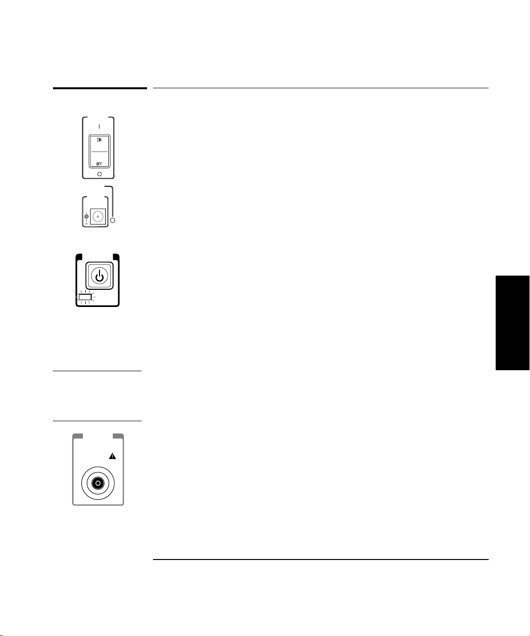
Chapter 2 Operating Your Instrument
Measuring Frequency
Battery
Measuring Frequency
1 Connect the instrument to a power source.
When the instrument is connected to an AC power source, the Standby
indicator on the front panel lights. The Standby indicator also lights if the
Battery
Charging
EXT DC
11 to 18 VDC
+
POWER
Standby
CAUTION The Channel 2 input path circuits contain sensitive GaAs semiconductors.
instrument is connected to an external DC power source or is operated
from internal batteries and the battery power switch is on (with the
Battery option only).
2Press the POWER button on the front panel.
The Standby indicator goes off, and all segments of the front-panel display
are temporarily activated. TESTING is displayed while the instrument
performs its power-on self-test. If the instrument passes all of the tests,
SELF TEST OK is displayed, and the instrument then displays its model
number, firmware version number, GPIB address, and CH2 NO SIGNAL.
The Counter is now ready to measure the frequency of a signal applied
to the Channel 2 input. Note that the Ch 2 and Freq annunciators
are activated.
3 Connect an input signal to Channel 2.
To prevent damage to these components, always adhere to standard ESD
(ElectroStatic Discharge) prevention procedures, and ensure that the
maximum power specification for this channel (+27 dBm) is not exceeded.
2
COUNTER
CHANNEL 2
50MHz to 26.5 GHz
DAMAGE
+27 dBm
50Ω
The Counter automatically displays the measured frequency of the input
signal. To set the resolution, measurement rate, and/or the number of
averages, see the appropriate procedure in the section titled “Operating
the Instrument,” or refer to “Setting the Resolution,” “Setting the
Measurement Rate,” and “Setting the Number of Averages,” later in
this chapter.
Operating and Programming Guide 2-11
Page 68
Chapter 2 Operating Your Instrument
Measuring Frequency
NOTE When the frequency of a signal applied to the Channel 2 input exceeds
the maximum rated frequency for the Counter, the Counter displays
CH2 TOO HIGH.
4 To measure the frequency of a signal applied to the Channel 1
input, press the Chan Select key.
CHANNEL 1 is displayed momentarily, and the Ch 1 and Freq annunciators
are activated. If a signal is presently applied to the Channel 1 input,
the measured frequency is then displayed. If no signal is applied,
CH1 NO SIGNAL is displayed until an input signal is connected to the
Chan
Select
Gate
C
Channel 1 input connector.
2
2-12 Operating and Programming Guide
Page 69
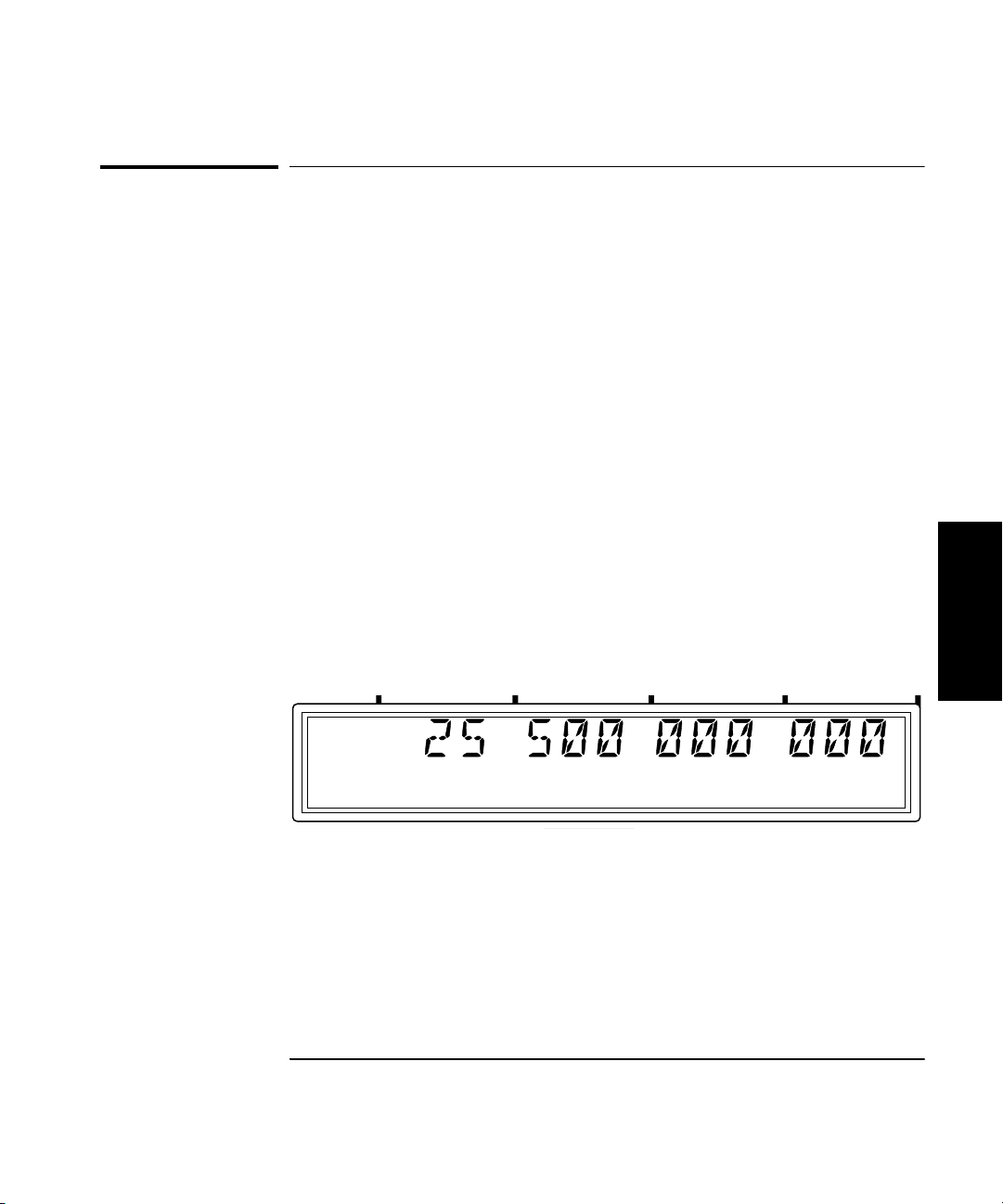
Chapter 2 Operating Your Instrument
Setting the Resolution and Measurement Rate
Setting the Resolution and Measurement Rate
The number of measurements the Counter makes in a given amount of
time is affected by the Rate setting, the Resolution setting, and the quality
of the input signal (signal quality affects the amount of time the Counter
requires to determine an accurate measurement). By adjusting the
Resolution and Rate settings, you can affect how often the Counter
takes measurements.
Setting the Resolution
The Counter’s resolution setting determines the number of digits
displayed for measurements and the precision of the measurements.
Since less time is required to compute each measurement as the
resolution of the measurements is reduced, the resolution setting
also affects the rate at which measurements are taken and displayed.
As a result, the flash rate of the Gate indicator changes when you change
the resolution.
The numerals shown for the value of the measurement are displayed in
four groups of three digits, as shown below (the leading zero is suppressed):
2
Ch 2
Freq
GHz
MHz
kHz
Hz
Operating and Programming Guide 2-13
Page 70
Chapter 2 Operating Your Instrument
Reset/
Local
Freq
Offset
Menu
On/Off
Clear
Resol
Shift
Enter
Setting the Resolution and Measurement Rate
Resolution Setting Example
For the following example, use the 10 MHz output from the reference
timebase as the input to Channel 1.
1 Press the Resol key to enter the resolution-setting mode.
The current resolution setting is displayed (the current value and the
indicator between the arrow keys are flashing to indicate that you can use
the up- and down-arrow keys to change the setting).
2 Press the up-arrow or down-arrow key to decrease or increase
the resolution.
You can press these keys as many times as necessary to locate the setting
you want to use. The available resolution settings are 1 Hz (the default),
10 Hz, 100 Hz, 1 kHz, 10 kHz, 100 kHz, and 1 MHz.
3Press the Enter key to activate your setting and exit the
resolution-setting mode.
2
The setting you chose is now in effect. The number of digits displayed for
the measurement is adjusted accordingly; you can observe the affect on
measurement speed by monitoring the flash rate of the Gate indicator.
NOTE The measurement resolution has a direct effect on the amount of time the
Counter requires to complete a measurement. Measurements made at the
Counter’s maximum resolution setting (1 Hz) are noticeably slower than
at lower resolutions. This is especially noticeable when the Counter is set
to average a number of measurements.
2-14 Operating and Programming Guide
Page 71
Chapter 2 Operating Your Instrument
MODIFY
Cal
Factor
Enter
Avg
+ / -
Freq
Rate
Pwr
Offset
Hold
Setting the Resolution and Measurement Rate
Setting the Measurement Rate
The measurement Rate setting determines how frequently the instrument
initiates measurements (frequency, power, and/or voltage). Since the
actual measurement rate is also affected by the Counter’s resolution
setting and the signal quality, as mentioned earlier, the available rate
settings (FAST, MED, and SLOW) do not equate to a fixed number of
measurements in a given amount of time. The HOLD setting turns off
automatic measurements, so that a single measurement is made each
time you press the Reset/Local key.
Rate Setting Example
1 Press the Rate key to enter the rate-setting mode.
The current rate setting is displayed (the current value and the indicator
between the arrow keys are flashing to indicate that you can use the upand down-arrow keys to change the setting).
2 Press the up-arrow or down-arrow key to decrease or increase
the measurement rate.
You can press these keys as many times as necessary to locate the setting
you want to use. The available resolution settings are FAST, MED, SLOW,
and HOLD.
2
3Press the Enter key to activate your setting and exit the rate-
setting mode.
The setting you chose is now in effect. The measurement rate is adjusted
accordingly; you can observe the effect on measurement speed by
monitoring the flash rate of the Gate indicator. The rate annunciator is
activated when either SLOW or MEDIUM is selected for the rate. When
you select HOLD, the HOLD annunciator is activated.
4 If you set the rate to HOLD, press the Reset/Local key to initiate
a measurement.
The instrument computes the measurement and then displays the result
(if averaging is enabled, the instrument displays the AVERAGING
message while it computes the measurement). Press the Reset/Local key
again each time you want to take an additional measurement.
Operating and Programming Guide 2-15
Page 72
Chapter 2 Operating Your Instrument
Pwr
Offset
+/–
Avg
Setting the Number of Averages
Setting the Number of Averages
You can set the instrument to take a variable number of frequency, power,
or voltage measurements and average them mathematically before
displaying the result. You can use this feature to determine the effective
measurement of a signal that is fluctuating. When measuring the
frequency of a fluctuating signal, you can also use averaging to retain
some of the precision of a maximum-resolution measurement.
The default number of averages is 1, which means that no averages are
performed, and the maximum setting is 99. Note that the tens position
(10 through 90) and the units position (0 through 9) are adjusted
separately, and that it is not possible to set the number of averages to 0.
NOTE When a large number of averages is selected for a frequency measurement
in combination with a high resolution setting (e.g., 1 Hz), it takes a
considerable amount of time for the instrument to take the measurements,
compute the averages, and display an initial reading. For example, when
2
the number of averages is set to 60, and the resolution is set to 1 Hz, the
first reading is displayed after 60 seconds (approximately). Subsequent
computations do not require as much time, since the averaging function
computes a running average. However, the rate at which the display is
updated after the initial average computation is also slower than at lower
resolution settings.
Averages Setting Example
1 Press the Avg key to enter the averages-setting mode.
The current averages setting is displayed (the current value and the
indicator between the arrow keys are flashing to indicate that you can use
the up- and down-arrow keys to change the setting).
2 Press the up-arrow or down-arrow key to decrease or increase the
value for the units position of the number of averages.
2-16 Operating and Programming Guide
Page 73
Chapter 2 Operating Your Instrument
Ch 12
Rel Freq
Avg On
Setting the Number of Averages
NOTE For most of the instrument’s settings, when you continue to press either
the up-arrow or the down-arrow key when you reach the end of the
available settings, the value for the setting “rolls over” to the value at the
opposite end of the range. For example, if the GPIB address is set to 31,
and you press the up-arrow key, the value changes to 1. However, when
you adjust the value in the units position for the number of measurements
to be averaged, rollover does not occur. If you press the up-arrow when the
value in the tens position is 0 and the value in the units position is 9, or if
you press the down-arrow when the value in the tens position is 0 and the
value in the units position is 1, there is no change. If the value in the units
position could roll over (in either direction), it would allow you to set a
value of 0 for the number of averages. Since at least one measurement
must be taken, 0 is an illegal value.
3 Press the left-arrow key once to move the focus to the tens
position, and then use the up- and/or down-arrow key to set the
value for the tens position (if desired).
Note that the tens and units values are set separately.
4Press the Enter key to activate your setting and exit the averages-
setting mode.
The Avg On annunciator is activated, and the instrument displays
AVERAGI N G while it takes the first set of measurements. The length of
time that the AVERAGING message is displayed varies primarily with
setting for the number of averages, since this determines the number
of measurements that must be made and averaged before displaying a
result. When the first set of averages is complete and the result is
displayed, the instrument immediately takes another measurement,
discards the oldest measurement included in the current average
computation, recomputes the average and displays the new result.
This continues until you change the setting for the number of averages
or disable averaging (by setting the number of averages to 0).
In certain situations, the length of time that the AVERAGING message is
displayed can be affected by additional factors. When you are measuring
frequency, the current resolution setting, the rate setting, and the quality
of the signal all affect the length of time required to make the
measurements and complete the average computation.
Operating and Programming Guide 2-17
2
Page 74

Chapter 2 Operating Your Instrument
Setting the Number of Averages
NOTE If the measurement rate is set to HOLD, and a value larger than 1 is set
for averages, the first set of measurements is not initiated until you
press the Reset/Local key. When you do, the instrument displays the
AVERAGING message while it takes the first set of measurements.
When the first set of measurements is complete, and the averaging result
is displayed, the instrument remains in this state until you press the
Reset/Local key to initiate another set of measurements, change the value
for averages back to one, or change the setting for the measurement rate
to SLOW, MED, or HIGH. When the measurement rate is set to HOLD, the
instrument performs a block-average computation instead of a runningaverage computation.
2
2-18 Operating and Programming Guide
Page 75

Chapter 2 Operating Your Instrument
Measuring Relative Frequency
Measuring Relative Frequency
You can measure the difference in frequency from one measurement to
another (frequency drift) or between two separate input signals using the
Relative Frequency function.
Relative Frequency Example
Press the Rel Freq key. The Shift annunciator activates when you press
the Shift key. When you press the Rel Freq key, the Rel Freq annunciator
in the upper-left corner of the display activates. At the same time, the
Counter saves the frequency measurement it was displaying at the time
you pressed the Rel Freq key, and it computes and displays the difference
between the stored measurement and all subsequent measurements until
the relative frequency function is deactivated.
You can also use the Relative Frequency function to measure the
difference between two different signals. To do this, activate the Relative
Frequency function, as described in the previous paragraph, disconnect
the cable supplying the signal to the input connector, and then connect the
second signal to the same input connector. The value displayed when the
Counter acquires the second signal is the frequency difference between
the two signals.
2
Operating and Programming Guide 2-19
Page 76
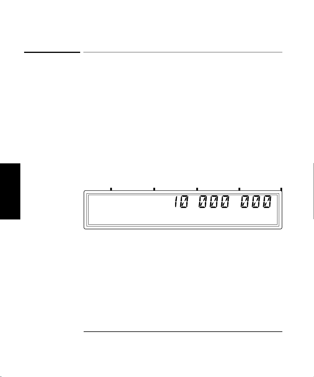
Chapter 2 Operating Your Instrument
Rel
Offsetting a Frequency Measurement
Offsetting a Frequency Measurement
You can use the Frequency Offset (Freq Offset) function to add or subtract
a constant value to/from a frequency measurement. For example, you can
use an offset to compensate for a systematic error or to display the
difference in frequency between two signals.
To display an offset frequency measurement, you need to set the value and
sign (+/–) of the offset and to turn the Frequency Offset function on.
Frequency Offset Example
1 Connect a cable from the 10 MHz reference output on the back
panel to the Channel 1 input connector, and press the Chan Select
key (if necessary) to activate Channel 1.
The display should look like this:
2
GHz
Ch 1
Freq
Rel
MHz
kHz
Hz
2Press the Shift key, and then press the Freq Offset (Resol) key in the
MODIFY section of the front panel.
The Shift annunciator activates when you press the Shift key. When you
press the Freq Offset key, the Shift annunciator disappears, and the Freq
Offset annunciator at the left side of the display activates.
2-20 Operating and Programming Guide
Page 77
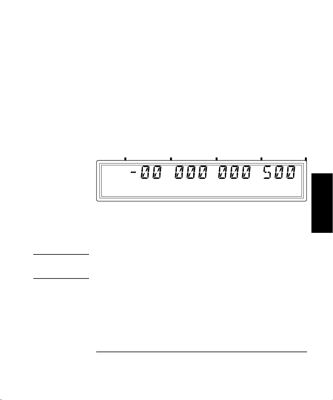
Chapter 2 Operating Your Instrument
Rel
Offsetting a Frequency Measurement
3 Use the left- and right-arrow keys to move the focus to the digit(s)
in the frequency-offset display that you need to adjust to enter the
offset value, and then use the up- and down-arrow keys to adjust
the value for each digit. Enter a value of 500 Hz.
The flashing digit is the digit that currently has the focus. This means
that you can change the value of the flashing digit using the up- and
down-arrow keys.
4 Press the sign (+/–) key (if desired) to change the sign of the
offset value.
The display should look like this:
GHz
Ch 1
Freq
Rel
Offset
MHz
kHz
Hz
5Press the Enter key to confirm the offset value and exit the
offset-entry display.
The Freq Offset annunciator is deactivated, and the measurement display
returns.
NOTE When you are entering a value for Frequency Offset (or Power Offset),
you can use the Reset key to restore all of the displayed digits to zero.
These are the only two functions in which the Reset key has this effect.
2
Operating and Programming Guide 2-21
Page 78
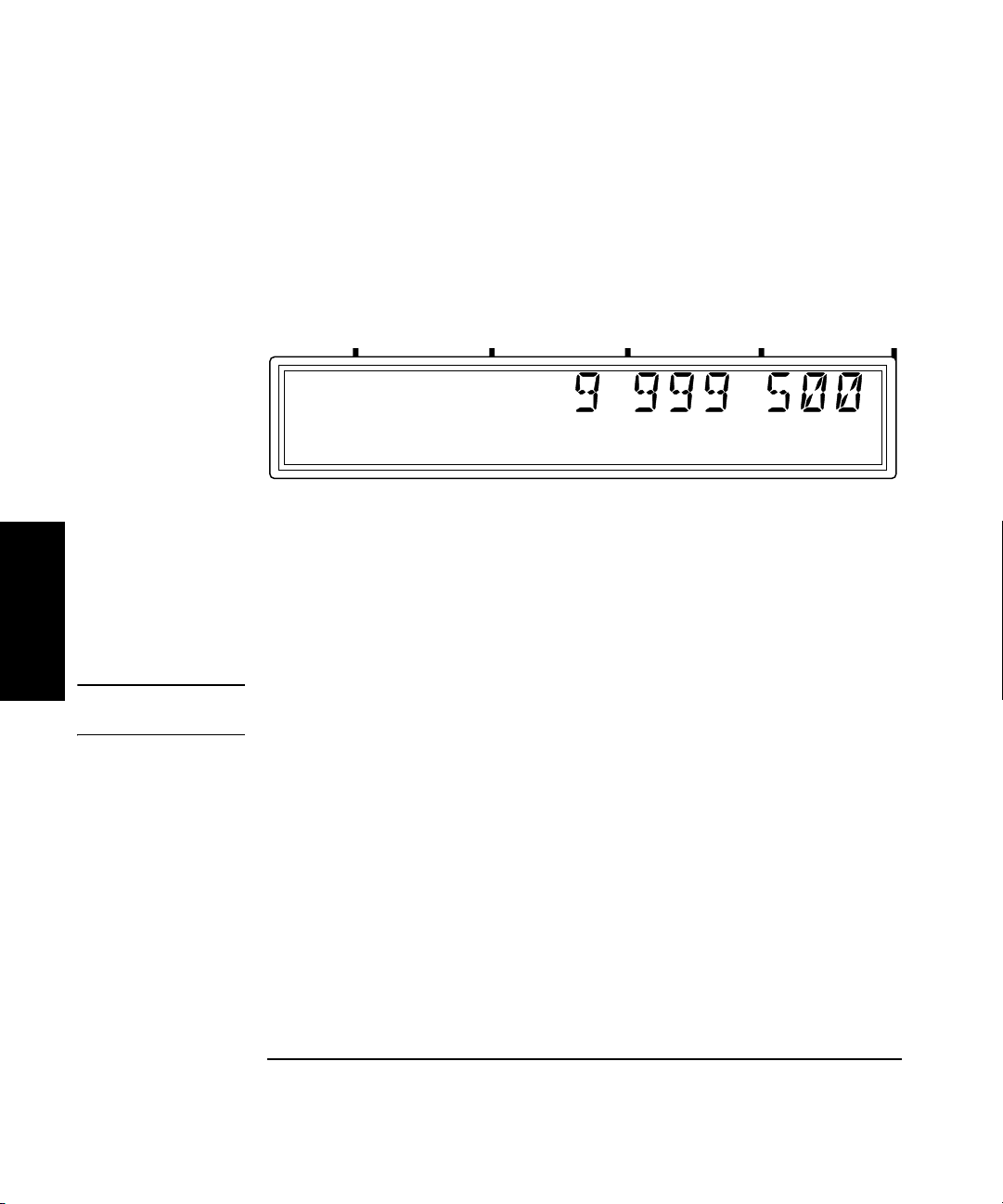
Chapter 2 Operating Your Instrument
Offsetting a Frequency Measurement
6Press the Offset On/Off key in the COUNTER section of the
front panel.
The Freq Offset annunciator is activated, and the value of the display is
adjusted to reflect the value and sign of the offset entered in Steps 2 and 3.
The display should look like this:
Ch 1
Rel Freq
Offset
GHz
MHz
kHz
Since the offset function can be used to add or subtract a fixed value
to/from the measurement result, you can use this feature to tune or align
the odd frequencies of a local oscillator (LO). If you enter the target
2
frequency as a negative offset, the Counter displays the difference
between the LO’s frequency and the target frequency. You can then adjust
the LO until the Counter displays a value of zero.
NOTE The maximum value that can be entered for Frequency Offset is
± 49,999,999,999 Hz.
Hz
2-22 Operating and Programming Guide
Page 79

Chapter 2 Operating Your Instrument
Measuring Power
Measuring Power
The Agilent 53147A/53148A/53149A can measure signal power in the
power and frequency ranges listed in the specifications in Chapter 4.
The power measurement, which is shown in a dedicated area of the
display, includes a digital readout and an analog representation.
The display, which can be configured to show power in units of dBm
or Watts, is auto-ranging when set to measure in Watts.
Selecting a Power Head (Sensor)
There are a number of Agilent power heads that can be used with the
Power Meter in this instrument. Choosing the appropriate power head is a
matter of matching the head’s characteristics to the signal to be measured.
Before you can make any power measurement, you must determine which
power head (sensor) to use for the measurement, select the power head in
the instrument’s menu (see “Using the Menu” on page 2-43), and configure
the Power Meter to use the appropriate calibration factor for the
frequency of the signal. The five power head models that have prerecorded calibration-factor tables in the instrument’s non-volatile memory
are listed under “Power Head Selection (HEAD)” on page 2-50.
2
You can also modify the data points (frequency/calibration-factor data
pairs) in the preconfigured calibration-factor tables, add data points to
these tables, and add up to three custom tables for power heads that are
not included in the instrument’s menu. Instructions for modifying and
adding data points in calibration-factor tables are provided in “Modifying
and Adding Calibration Factor Tables” on page 2-27.
Making a Power Measurement
When you turn the Power Meter on, you must always zero and calibrate it
with the power head connected before making any measurements. If you
are using a different model power head than the one used the last time the
Power Meter was used, you must also set the power head model in the
instrument’s menu. As part of the measurement sequence, you must input
either the frequency of the signal you intend to measure or the power
factor for that frequency (from the table provided with the power head).
Operating and Programming Guide 2-23
Page 80
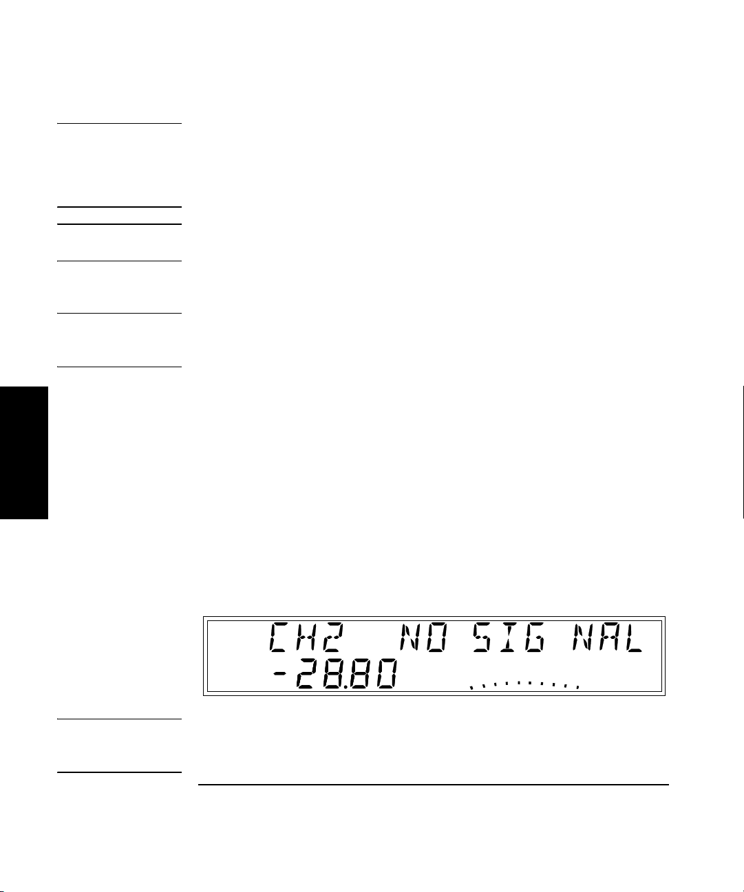
Chapter 2 Operating Your Instrument
Measuring Power
NOTE You must re-zero and recalibrate the Power Meter if you change the power
head, if the instrument is shut off for any period of time, if the ambient
temperature changes by 5
° C (9° F) or more, and if the GPIB “INIT”
command is sent to the instrument. In any case, you should calibrate
the Power Meter at least once a day.
CAUTION Always follow the directions provided with the power head in addition to
the instructions provided in this manual.
Power Measurement Example
NOTE The instrument must be powered on and must remain at the same ambient
temperature for 15 minutes before beginning this procedure. If the
temperature changes by 5° C (9° F) or more, wait another 15 minutes.
1 Connect the output cable from the power-meter head to the
Power Meter Input connector.
2
This example assumes that you have a power head available that is
appropriate for the measurement to be taken.
2Press the Display Power key to enable power measurement.
The Pwr annunciator at the left side of the display is activated, and the
Power Meter’s digital and analog power displays show the power
measurement in dB or dBm (the default units of power measurement).
The display should look like this:
Ch 2
Freq
dB
dBm
Pwr
Watts
mW
uW
%
NOTE When there is no signal applied to the power head, the Power Meter
reads the noise level, as shown in the illustration above. This reading is
generally below –25 dBm prior to zeroing and will vary.
2-24 Operating and Programming Guide
Page 81
Chapter 2 Operating Your Instrument
Measuring Power
NOTE The upper portion of the display may show a frequency measurement or a
voltage measurement if a signal is applied to the Counter or DVM input
and the Counter or DVM is enabled. In this example, the Counter is
enabled, but no signal is applied, so the upper portion of the display shows
CH2 NO SIGNAL. If the DVM is enabled with no signal applied, the upper
portion of the display will show VDC 0.000.
3Press the Shift key, and then press the Menu (Reset/Local) key.
One of the items in the instrument’s menu is displayed (if the menu has
not been used since the instrument was turned on, the initial menu
display is “REF OSC> INT”).
4 Use the up and/or down arrow keys to cycle through the menu
until “HEAD > OFF” is shown.
Note that a power head model number may appear instead of “OFF” if a
power head was previously chosen.
5 Press the right arrow key.
The flashing indicator after HEAD changes from to , and “OFF” (or the
currently selected power head model number) begins to flash.
6 Select the model number of the power head you intend to use by
pressing the up- and/or down-arrow key repeatedly until the
correct model number is displayed, and then press Enter.
NOTE You can change the values of the frequency/power-factor data points that
are stored in the instrument’s memory (or add data points) by pressing
the right-arrow key while a power-head model number is displayed
and pressing the right-arrow key again when “LIST” is displayed.
For instructions on entering or changing data, see “Numeric Entry” on
page 2-6.
The instrument is shipped with calibration tables in nonvolatile memory
for five of the supported power heads. The data points in these tables are
almost always sufficient to provide accurate readings, so it is usually
unnecessary to add or modify the values in the tables.
Operating and Programming Guide 2-25
2
Page 82

Chapter 2 Operating Your Instrument
Measuring Power
NOTE Three empty tables are provided for compatible power-sensor heads that
the instrument does not have pre-recorded tables for. You can create your
own table by entering a set of frequency/power-factor data points for a
power head by selecting CUST 1, CUST 2, or CUST 3 from the HEAD
menu. You then enter a set of frequency/power factor data points for the
power head. For instructions on entering or changing data, see “Numeric
Entry” on page 2-6.
7Press the Zero key.
The Power Meter displays ZEROING and then returns to the display
shown in Step 2.
8 Connect the power-head input connector to the Power Meter
Output connector.
9Press the Cal key.
During calibration, the Power Meter displays CALIBRATING. It then
2
returns to the display shown in Step 2.
10 If you know the frequency of the signal you intend to measure,
press the Freq key, enter the frequency value, and press Enter
(for instructions on entering or changing values, see “Numeric
Entry” on page 2-6).
The Power Meter uses the frequency to set the power-factor per the values
in the stored calibration tables. If you prefer, you can use the Cal Factor
key to enter the calibration factor value directly.
NOTE If the signal you intend to measure is already applied to one of the Counter’s
input channels, you can press the Store key (Shift + Cal) to input the
frequency value instead of using either the Freq or Cal Factor keys and
entering a value manually. This saves time and has the same effect.
2-26 Operating and Programming Guide
Page 83
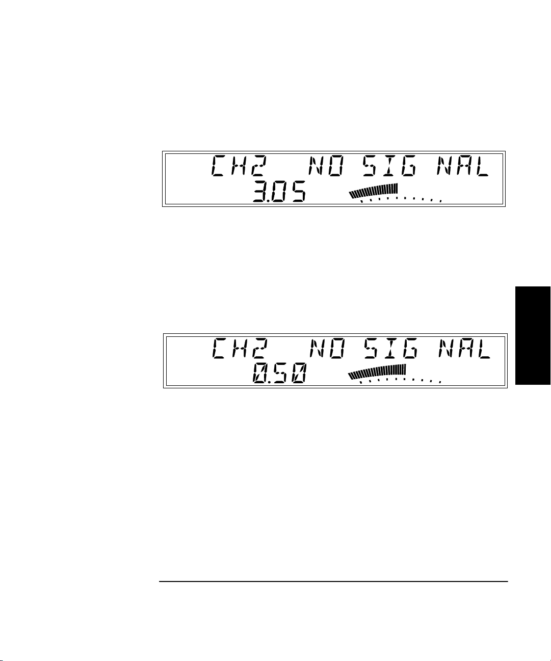
Chapter 2 Operating Your Instrument
Measuring Power
11 Disconnect the power-head input connector from the Power Meter
Output connector and connect it to the signal to be measured.
The Power Meter measures the signal power and displays it, as shown below:
Ch 2
Freq
dB
dBm
Pwr
Watts
mW
uW
%
12 To measure the signal power in Watts, press the Shift key, and
then press the dBm/W (Display Power) key.
When you press the Shift key, the Shift annunciator is activated. When you
press the dBm/W (Display Power) key, the Shift annunciator goes off, and
the units of measurement annunciator group to the right of the digital
power measurement changes from dB or dBm to Watts, mW, µW, or nW,
as shown below:
Ch 2
Freq
dB
dBm
Rel Pwr
Watts
mW
uW
%
Modifying and Adding Calibration Factor Tables
The HEAD menu option provides access to preconfigured, editable
calibration-factor tables for five models of Agilent power-sensor heads
(models 8481A, 8481D, 8482A, 8485A, and 8487A) and three custom
tables. You can modify the frequency/calibration-factor values in any of
the data points for any power head, and you can input data to build new
calibration tables (CUST 1, CUST 2, and CUST 3). Table 2-1 shows the
changes you can and cannot make to the various data points in the five
factory-configured calibration-factor tables (for models 8481A, 8481D,
8482A, 8485A, and 8487A) and the three custom calibration tables (CUST 1,
CUST 2, and CUST 3).
Operating and Programming Guide 2-27
2
Page 84
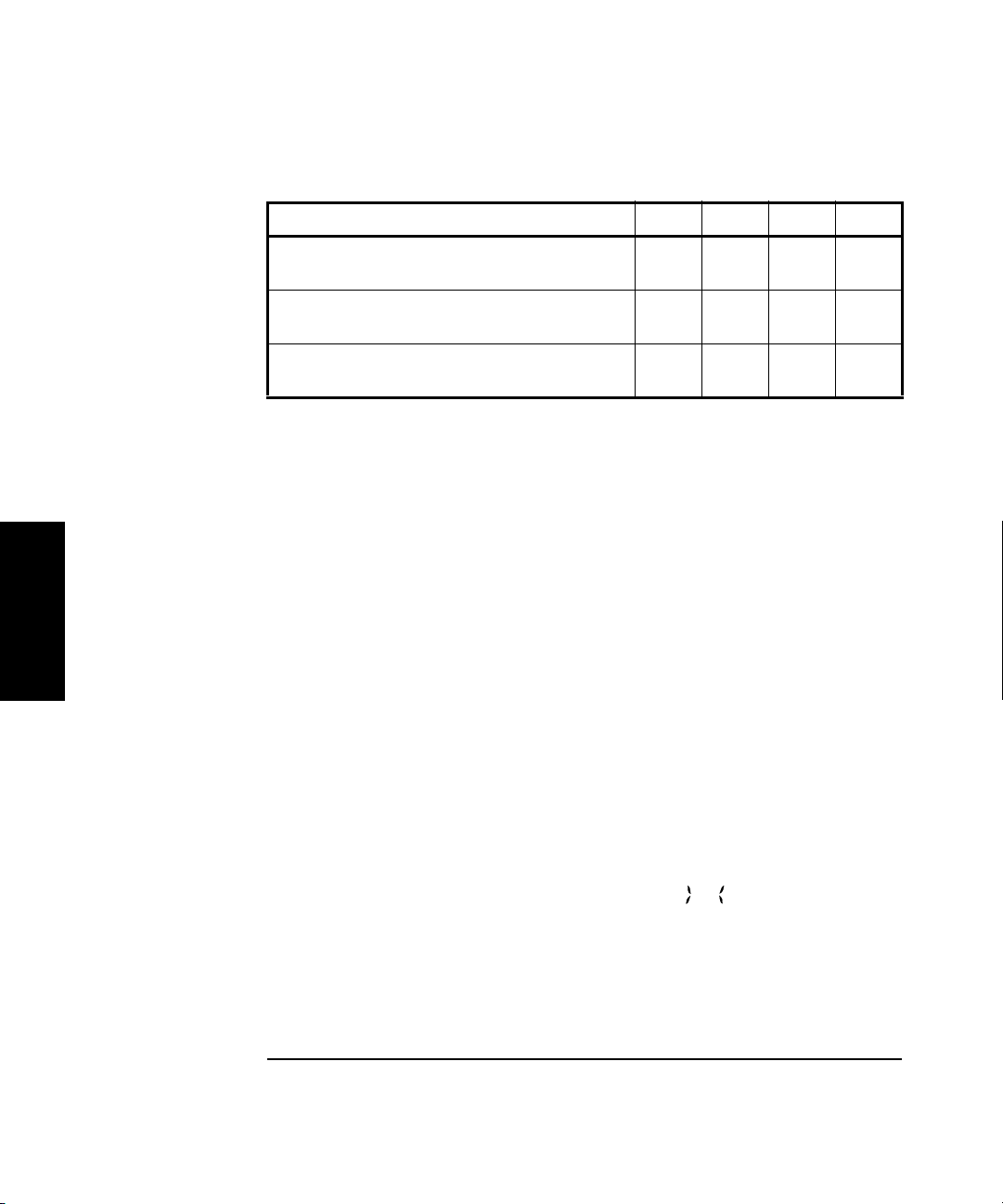
Chapter 2 Operating Your Instrument
Measuring Power
Table 2-1. Calibration Factor Data Point Modifications
Calibration Table Data Points Modify Delete Reset Add
Factory defined data points
(for 8481A, 8481D, 8482A, 8485A, and 8487A)
Data points added to factory-defined tables by user
Custom calibration-factor tables
(CUST1, CUST2, and CUST3)
All None All Yes
All All N/A N/A
All All N/A Ye s
Calibration Table Modification Example
This example demonstrates how to view and modify the values in any of
the preconfigured calibration tables or in one of the three custom
calibration tables.
1Press the Shift key, and then press the Menu (Reset/Local) key.
2
One of the items in the instrument’s menu is displayed (if the menu has
not been used since the instrument was turned on, the initial menu
display is “REF OSC> INT”).
2 Use the up and/or down arrow keys to cycle through the menu
until “HEAD > OFF” is shown.
Note that a power head model number (or CUST 1, CUST 2, or CUST 3)
may appear instead of “OFF” if a power-head model was previously
selected.
3 Press the right arrow key.
The flashing indicator after HEAD changes from to , and “OFF” (or the
currently selected power head model number) begins to flash.
2-28 Operating and Programming Guide
Page 85
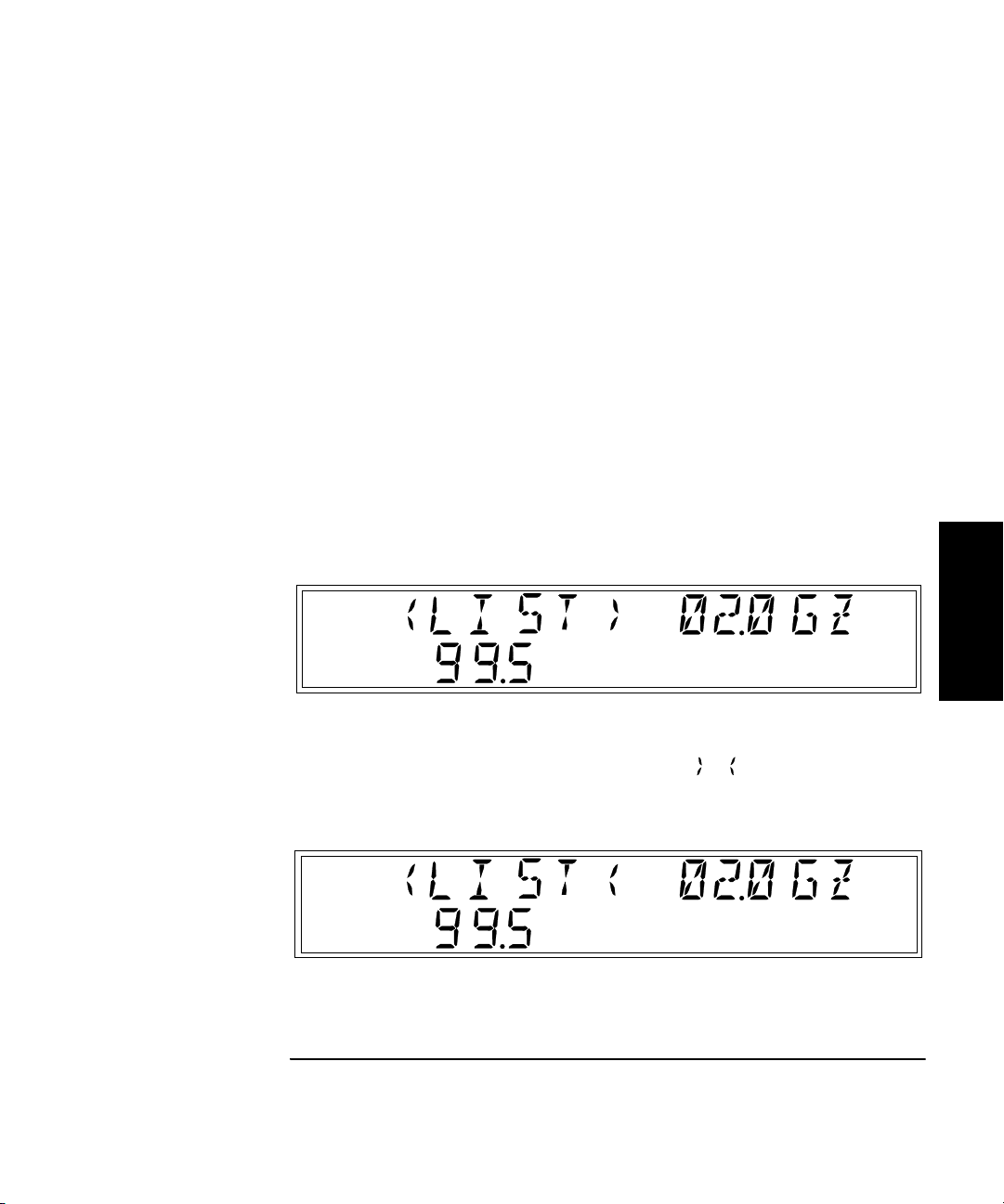
Chapter 2 Operating Your Instrument
Measuring Power
4 Select the model number of the power head you intend to modify
the data point(s) for by pressing the up- and/or down-arrow key
repeatedly until the correct model number is displayed, and then
press Enter.
You can now change the values of the frequency/power-factor data points
that are stored in the instrument’s memory (or add data points) by
pressing the right-arrow key while a power-head model number is
displayed and pressing the right-arrow key again when “LIST” is
displayed. For instructions on entering or changing data, see “Numeric
Entry” on page 2-6.
5 Press the right arrow key.
The display scrolls right-to-left and displays LIST and the frequency (on the
top line) and calibration-factor (on the bottom line) values in the first data
point. You can now use the up and down arrow keys to cycle through the
data points in the currently displayed calibration table.
Ch 2
Freq
Offset
Avg On
Pwr
Offset
dB
dBm
Watts
mW
uW
%
6 Press the right arrow key again.
The flashing indicator after LIST changes from to , and the first digit in
the frequency value begins to flash. You can now use the up and down
arrow keys to change the value of the first digit of the frequency value.
Ch 2
Freq
Offset
Avg On
Pwr
Offset
dB
dBm
Watts
mW
uW
%
You can also use the right and left arrow keys to move between the digits
of the frequency value and use the up and down arrow keys to change the
values of these digits.
Operating and Programming Guide 2-29
2
Page 86
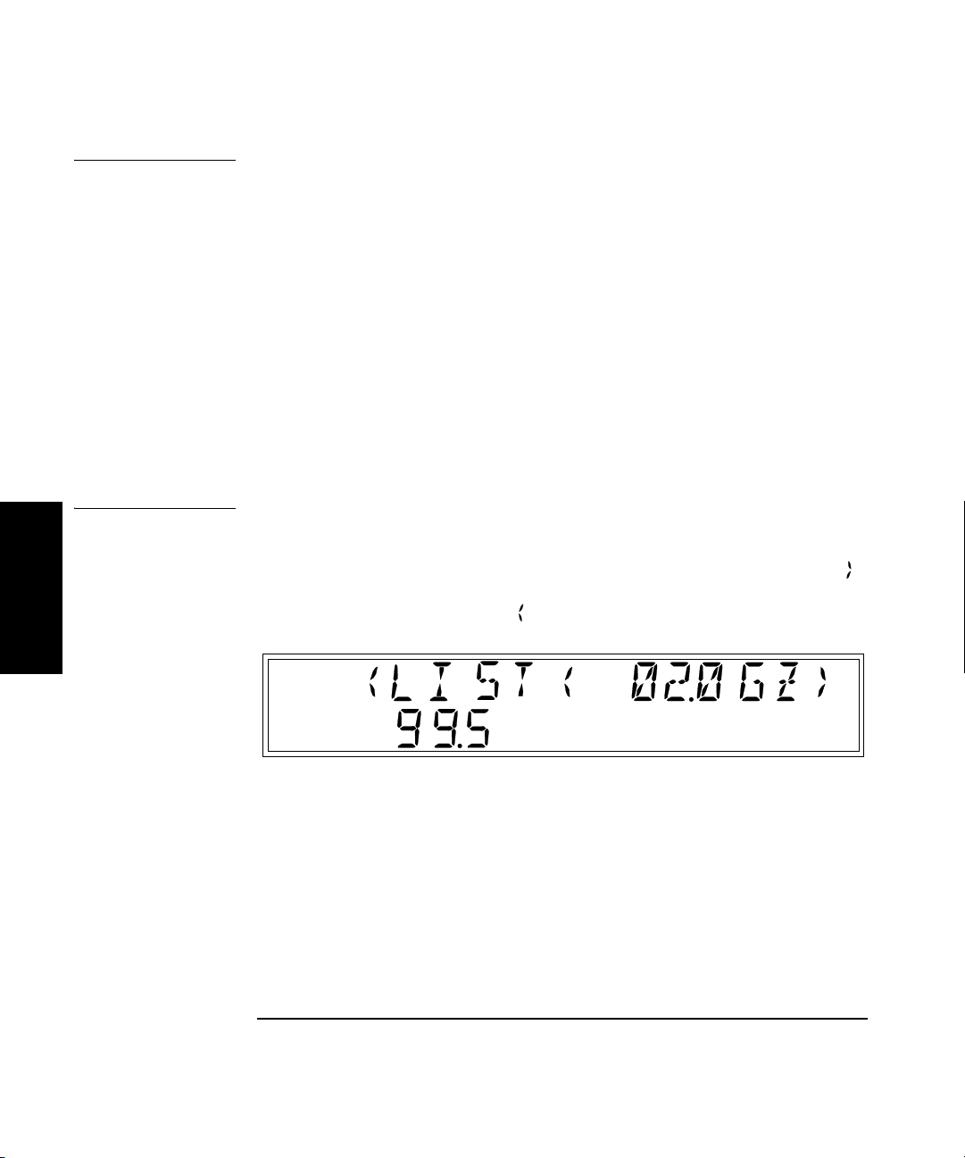
Chapter 2 Operating Your Instrument
Measuring Power
NOTE In instruments that have firmware that is modified as described in Service
Note 53147/8/9A-01, you can change the instrument’s setting to match
the 50 MHz reference calibration factor (RCF) of your power head.
When the frequency reading on the display is 00.05 GZ (50 MHz), you can
change the RCF to the one for your particular power head. After doing
this, always re-zero and recalibrate the instrument (see Steps 7 through 9
on page 2-26).
All units shipped from the factory after August 2001 have the modified
firmware installed. To determine whether your instrument has the
modified firmware, display the menu as described in “Sequencing
Through the Menu” on page 2-5. The instrument’s model number is listed
between the Preset and Op Hours menu items. Press the right arrow key
once to display the model number. If your instrument’s model number is
any number lower than 2060166-99, you should obtain and install the
firmware kit (Agilent part number 53147-80018).
7 When you move the focus to the last digit of the frequency value
(the one furthest to the right), an additional flashing indicator ( )
2
appears at the right end of the display, and the indicator to the
left of the frequency value ( ) stops flashing.
Ch 2
Freq
Offset
Avg On
Pwr
Offset
dB
dBm
Watts
mW
uW
%
This indicates that, in addition to being able to use the up and down arrow
keys to adjust the value of the flashing digit in the frequency value, you
can also press the right arrow key to move the focus from the last digit of
the frequency value to the first digit of the calibration-factor value.
2-30 Operating and Programming Guide
Page 87
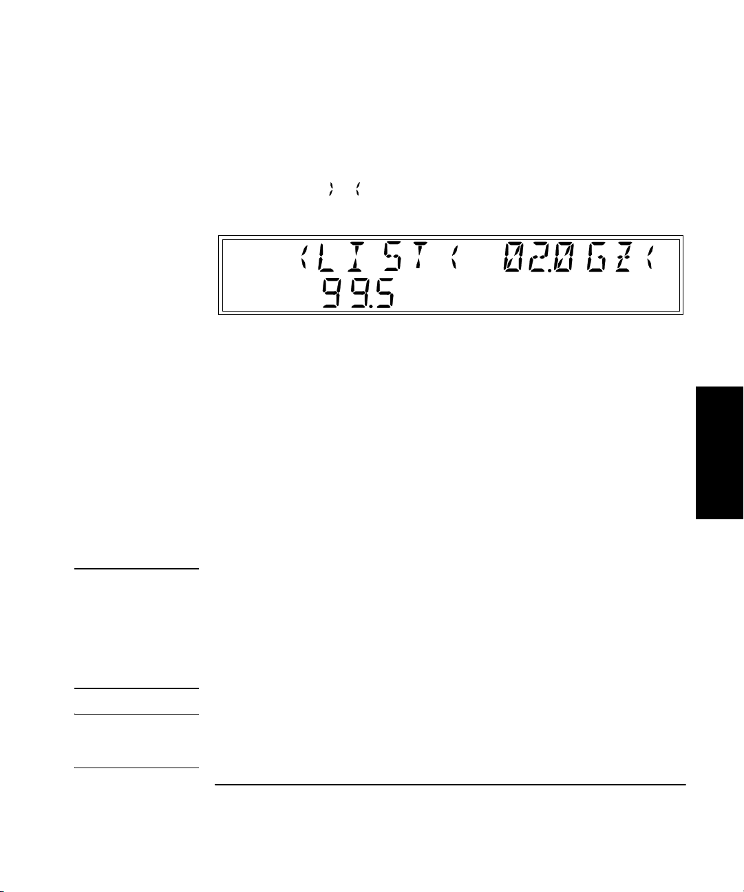
Chapter 2 Operating Your Instrument
Measuring Power
8 Press the right arrow key until the focus moves from the last
digit of the frequency value to the first digit of the calibrationfactor value (the first calibration-factor digit begins flashing).
The flashing indicator at the right of the frequency value changes
direction (from to ), which indicates that you can use the left
arrow to return to the frequency value, if you need to.
Ch 2
Freq
Offset
Avg On
Pwr
Offset
dB
dBm
Watts
mW
uW
%
You can now use the left and right arrow keys to move between the digits
of the calibration-factor, and you can use the up and down arrow keys to
adjust the values of the individual digits of the calibration-factor.
9 If you want to change values in additional data points, press the
right arrow key to save your changes and move to the next data
point. If you are done changing data point values, press the Enter
key to save your changes and exit the menu.
2
Whether you save and move to the next data point or save and exit, all of
the data points in the current table are immediately resorted into order by
frequency. This is important to keep in mind, since the next data point in
order may no longer be the same one that was in that position in the list
before you made changes to the data point you just adjusted.
NOTE You can use the same steps to create a calibration table for a power head
model that the Power Meter does not have a preconfigured calibration
table for, or you can create an alternate calibration table for one of the five
power head models that does have a preconfigured table. To do this,
simply choose CUST 1, CUST 2, or CUST 3 from the HEAD menu option
instead of choosing one of the preconfigured tables identified with a
power-head model number.
NOTE To delete a data point entirely, set the calibration-factor to a value of 50 or
lower. When you move to the next data point or exit the menu, the data
point containing the =< 50 value is automatically deleted from the table.
Operating and Programming Guide 2-31
Page 88
Chapter 2 Operating Your Instrument
Measuring Power
Table 2-2 lists the factory-set values in all of the data points for all five of
the pre-recorded power head calibration tables.
Table 2-2. Calibration Table Data-Point Values
Power Head Model Number Frequency Calibration Factor
8481A
2
RCF 100.0
50 MHz 100.0
100 MHz 99.8
2 GHz 99.0
3 GHz 98.6
4 GHz 98.0
5 GHz 97.7
6 GHz 97.4
7 GHz 97.1
8 GHz 96.6
9 GHz 96.2
10 GHz 95.4
11 GHz 94.9
12.4 GHz 94.3
13 GHz 94.3
14 GHz 93.2
15 GHz 93.0
16 GHz 93.0
17 GHz 92.7
18 GHz 91.8
2-32 Operating and Programming Guide
Page 89
Chapter 2 Operating Your Instrument
Measuring Power
Table 2-2. Calibration Table Data-Point Values (continued)
Power Head Model Number Frequency Calibration Factor
8481D
RCF 99.0
50 MHz 99.0
500 MHz 99.5
1 GHz 99.4
2 GHz 99.5
3 GHz 98.6
4 GHz 98.6
5 GHz 98.5
6 GHz 98.5
7 GHz 98.6
8 GHz 98.7
9 GHz 99.5
10 GHz 98.6
11 GHz 98.7
12 GHz 99.0
12.4 GHz 99.1
13 GHz 98.9
14 GHz 99.4
15 GHz 98.9
16 GHz 99.1
17 GHz 98.4
18 GHz 100.1
2
Operating and Programming Guide 2-33
Page 90
Chapter 2 Operating Your Instrument
Measuring Power
Table 2-2. Calibration Table Data-Point Values (continued)
Power Head Model Number Frequency Calibration Factor
8482A
RCF 98.0
0.1 MHz 98.0
0.3 MHz 99.5
1 MHz 99.3
3 MHz 98.5
10 MHz 98.5
30 MHz 98.1
100 MHz 97.6
300 MHz 97.5
1 GHz 97.0
2 GHz 95.0
3 GHz 93.0
4.2 GHz 91.0
2
2-34 Operating and Programming Guide
Page 91
Chapter 2 Operating Your Instrument
Measuring Power
Table 2-2. Calibration Table Data-Point Values (continued)
Power Head Model Number Frequency Calibration Factor
8485A
RCF 100.0
50 MHz 100.0
2 GHz 99.5
4 GHz 98.9
6 GHz 98.5
8 GHz 98.3
10 GHz 98.1
11 GHz 97.8
12 GHz 97.6
12.4 GHz 97.6
14 GHz 97.4
16 GHz 97.0
17 GHz 96.7
18 GHz 96.6
19 GHz 96.0
20 GHz 96.1
21 GHz 96.2
22 GHz 95.3
23 GHz 94.9
24 GHz 94.3
25 GHz 92.4
26 GHz 92.2
26.5 GHz 92.1
2
Operating and Programming Guide 2-35
Page 92
Chapter 2 Operating Your Instrument
Measuring Power
Table 2-2. Calibration Table Data-Point Values (continued)
Power Head Model Number Frequency Calibration Factor
8487A
2
RCF 100.0
50 MHz 100.0
100 MHz 99.9
500 MHz 98.6
1 GHz 99.8
2 GHz 99.5
3 GHz 98.9
4 GHz 98.8
5 GHz 98.6
6 GHz 98.5
7 GHz 98.4
8 GHz 98.3
9 GHz 98.3
10 GHz 98.3
11 GHz 98.1
12 GHz 97.9
13 GHz 98.0
14 GHz 98.2
15 GHz 97.7
16 GHz 96.8
17 GHz 97.0
18 GHz 96.3
19 GHz 95.9
20 GHz 95.2
21 GHz 95.6
22 GHz 95.5
23 GHz 95.4
24 GHz 95.0
25 GHz 95.4
26 GHz 95.2
27 GHz 95.1
28 GHz 95.0
29 GHz 94.4
30 GHz 94.0
31 GHz 93.7
2-36 Operating and Programming Guide
Page 93
Chapter 2 Operating Your Instrument
Measuring Power
Table 2-2. Calibration Table Data-Point Values (continued)
8487A (continued)
32 GHz 93.8
33 GHz 93.0
34 GHz 93.2
34.5 GHz 93.5
35 GHz 93.1
36 GHz 92.0
37 GHz 92.4
38 GHz 90.9
39 GHz 90.3
40 GHz 91.4
41 GHz 90.6
42 GHz 89.9
43 GHz 89.1
44 GHz 88.1
45 GHz 86.9
46 GHz 85.8
47 GHz 85.4
48 GHz 83.2
49 GHz 81.6
50 GHz 80.2
2
Operating and Programming Guide 2-37
Page 94
Chapter 2 Operating Your Instrument
Ch 12
Rel Freq
Rel Pwr
Measuring Relative Power
Measuring Relative Power
You can measure the difference in power from one measurement to another
or between two separate input signals using the Relative Power function.
Relative Power Example
Press the Shift key, and then press the Rel Pwr (POWER METER: Offset
On/Off) key. The Shift annunciator activates when you press the Shift key.
When you press the Rel Pwr key, the Shift annunciator disappears, and
the Rel Pwr annunciator at the left side of the display activates. At the
same time, the Power Meter saves the power measurement it was displaying
at the time you pressed the Rel Pwr key, and it computes and displays the
difference in power between the stored measurement and all subsequent
measurements until the relative power function is deactivated.
NOTE When the Power Meter is set to measure power in dBm, relative power is
expressed in dB. When the Power Meter is set to measure power in Watts,
2
relative power is expressed as a percentage (%).
You can also use the Relative Power function to measure the difference in
power between two different signals. To do this, activate the Relative
Power function, as described in the previous paragraph, disconnect the
signal to the power head (sensor), and then connect the second signal to
the same power head. The value displayed when the Power Meter
acquires the second signal is the power difference between the two signals.
2-38 Operating and Programming Guide
Page 95
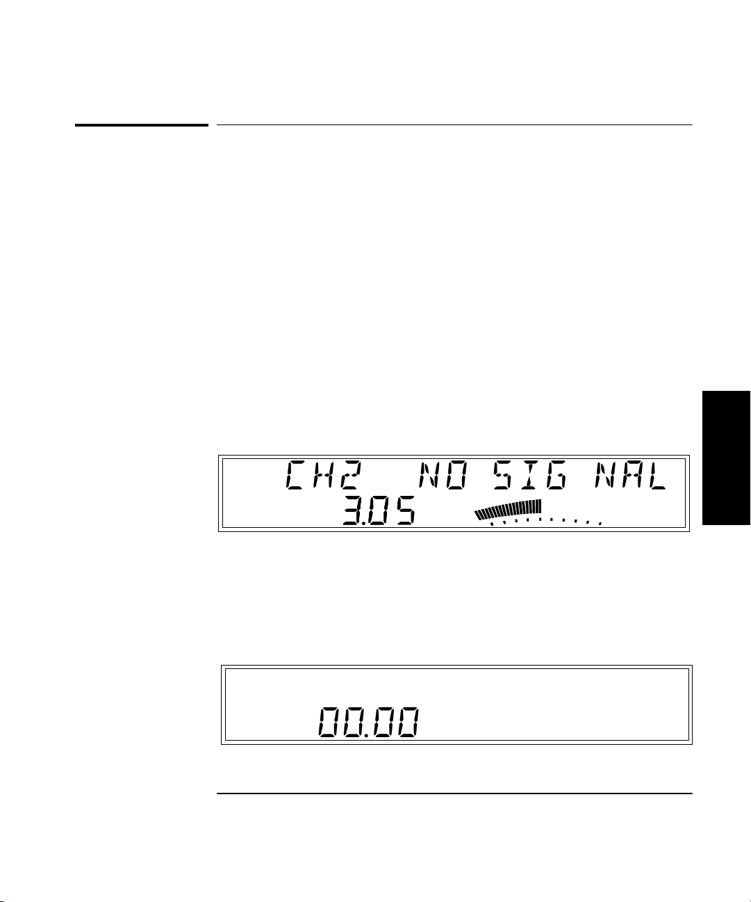
Chapter 2 Operating Your Instrument
Offsetting a Power Measurement
Offsetting a Power Measurement
You can use the power offset (Pwr Offset) function to add or subtract a
constant value to/from a power measurement. For example, you can use
an offset to compensate for a systematic error, to display the difference
in power between two signals, or to compensate for losses and
attenuation in cables or components that are between the signal source
and the Power Meter.
To display an offset power measurement, you set the value and sign (+/–)
of the offset and turn the Power Offset function on.
Power Offset Example
1 Connect a signal to the Power Meter input connector, and activate
power measurement by pressing the Display Power key.
The display should look like this (the values are simulated in these
illustrations):
Ch 2
Freq
dB
dBm
Pwr
Watts
mW
uW
%
2
2Press the Shift key, and then press the Pwr Offset (Avg) key.
The Shift annunciator activates when you press the Shift key. When you
press the Pwr Offset key, the Shift annunciator and the frequency display
disappear, the Pwr Offset annunciator at the left side of the display
activates, and the power-offset value is set to 00.00, as shown below:
Ch 12
Rel Freq
dB
dB
Rel Pwr
Offset
Watts
mW
uW
%
Operating and Programming Guide 2-39
Page 96
Chapter 2 Operating Your Instrument
Offsetting a Power Measurement
NOTE If the power-offset value was previously changed, the previous value is
displayed instead of 00.00.
3 Use the left- and right-arrow keys to move the focus to the digit(s)
in the power-offset display that you need to adjust to enter the
offset value, and then use the up- and down-arrow keys to adjust
the value for each digit.
The flashing digit is the digit that currently has the focus. This means
that you can change the value of the flashing digit using the up- and
down-arrow keys.
4 Press the sign-change (+/–) key (if desired) to change the sign of
the offset value.
Ch 12
Rel Freq
dB
dBm
Rel Pwr
Offset
Watts
mW
uW
%
2
2-40 Operating and Programming Guide
Page 97
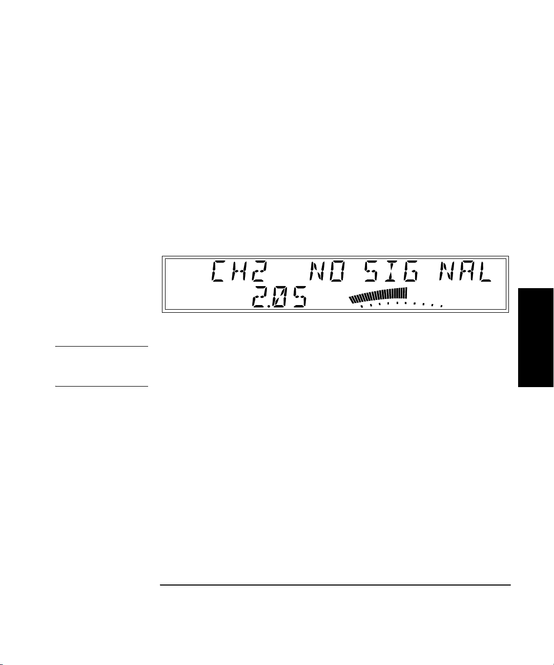
Chapter 2 Operating Your Instrument
Offsetting a Power Measurement
5Press the Enter key to confirm the offset value and exit the offset-
entry display.
The Pwr Offset annunciator is deactivated, and the measurement display
returns.
6Press the Offset On/Off key (in the POWER area of the front panel).
The Pwr Offset annunciator is activated, and the value of the display is
adjusted to reflect the value and sign of the offset entered in Steps 3 and 4.
The display should now look like this (values are simulated):
Ch 2
Freq
dB
dBm
Rel Pwr
Offset
Watts
mW
uW
%
NOTE When you are entering a power- or frequency-offset value, you can use the
Reset key to restore all of the displayed digits to zero. These are the only
two functions in which the Reset key has this effect.
Operating and Programming Guide 2-41
2
Page 98
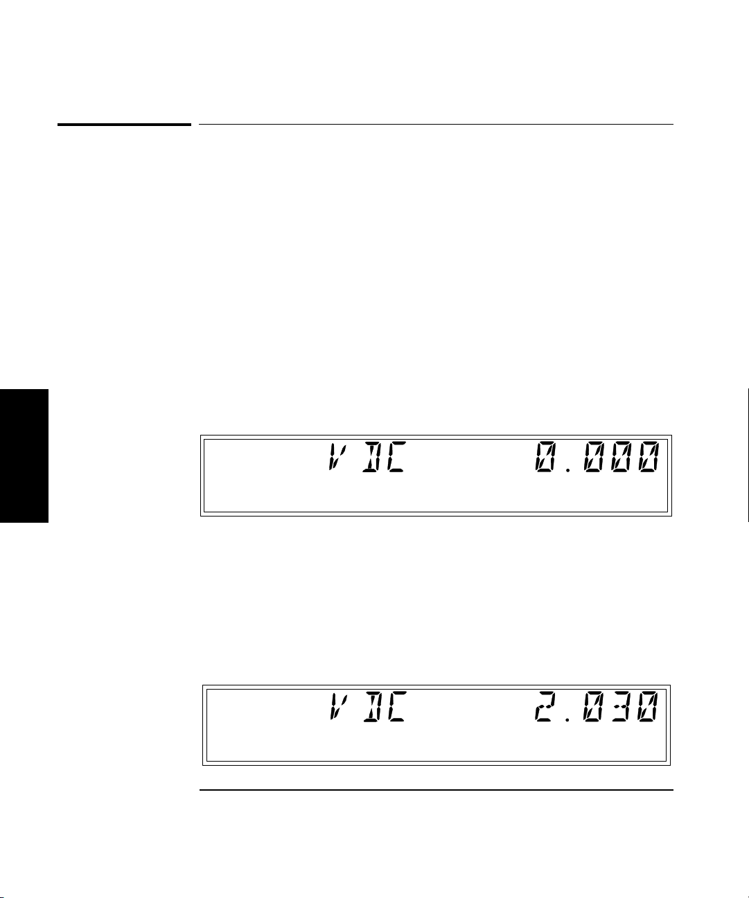
Chapter 2 Operating Your Instrument
Measuring Voltage
Measuring Voltage
The Agilent 53147A/148A/149A included a digital voltmeter (DVM) that
can measure voltages from – 50 VDC to +50 VDC. To measure voltage,
use the following procedure:
Voltage Measurement Example
1 If the instrument is not already turned on, connect the power
cord to the power-input connector on the rear panel and to an
appropriate power source (or, with the Battery option, turn on
the Battery power switch).
2Press the Display DVM key in the DVM section of the front panel.
The DVM display is activated, as shown below:
2
3 Insert the connector on the end of the red test lead into the red
+ DVM connector, and insert the connector on the black test lead
into the black – DVM connector.
4 Touch the red and black test prods to the points at which you
want to measure the voltage.
The display should look like this (assuming a voltage source of +2.030 VDC):
2-42 Operating and Programming Guide
Page 99
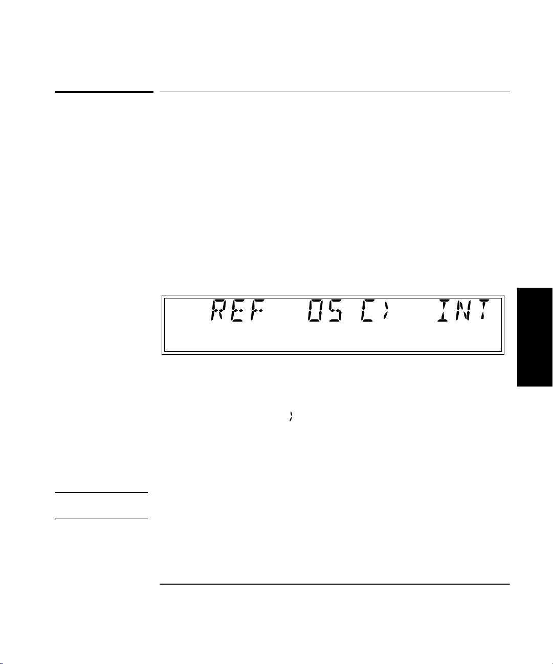
Chapter 2 Operating Your Instrument
Using the Menu
Using the Menu
The Agilent 53147A/148A/149A’s Menu makes it easy to control a number
of the instrument’s features and functions. You use the Selection (arrow)
keys to navigate to the setting you want to change and then to actually
make the changes.
1Press the Shift key and then the Menu (Reset/Local) key to display
the Menu.
When you press the Shift key, the Shift annunciator (near the bottom-right
corner of the display) activates. When you press the Menu (Reset/Local)
key, the Shift annunciator goes off, and the first menu item is displayed.
If you have not previously invoked the Menu since you last turned the
instrument on, the first menu item is REF OSC, the Reference Oscillator.
2 Press the right-arrow key to change the setting for the Reference
Oscillator.
The flashing annunciator ( ) in the display reverses direction to indicate
that you can now change the setting by pressing either the up-arrow key
or the down-arrow key. In the case of the Reference Oscillator function,
which has only two possible settings (INTernal and EXTernal), pressing
either the up- arrow or the down-arrow has the same effect (it toggles the
setting from INT to EXT or from EXT to INT).
NOTE The Counter will not switch to EXT (external) unless a suitable reference
signal is available at the External Reference connector.
Operating and Programming Guide 2-43
2
Page 100

Chapter 2 Operating Your Instrument
Using the Menu
3Press the Enter key to activate the setting and exit the Menu.
The setting you chose is put into effect, and the Menu closes.
If you need to exit the Menu without changing any of the settings, press
the Clear key. To restore the setting of any menu item to the setting that
was in effect when you opened the Menu, press the Reset/Local key
(this restores the original setting for the current menu item but does not
close the Menu).
The Menu contains the following items (these items are displayed in the
order they are listed if you repeatedly press the up-arrow key after
opening the Menu):
• REF OSC — Sets the Counter to use the internal timebase (INT) or an
external timebase (EXT) connected to the Reference connector on the
back panel.
• PWR REF — Turns the reference signal available on the Power Meter
Output connector ON or OFF.
2
• SAVE — Saves a copy of the current user settings in non-volatile
memory. Nine sets (0 – 8) can be saved, and Set 0 is automatically read
on startup.
• RECALL — Reads and implements a stored set of user settings from
one of nine (0 – 8) that are stored in non-volatile memory.
• CH1 LPF — Turns the Channel 1 Low-Pass Filter (approx. 50 kHz)
ON or OFF.
• FM — Turns the Counter’s ability to compensate for frequency
modulation on (AUTO) or OFF.
• BAUD — Sets the data rate for the RS-232 serial port (1200, 2400,
4800, 9600, 14400, or 19200).
• PRESET — Resets all functions to the factory-default settings.
• Model number, firmware version number, serial number, OPTNS
(installed options).
• OP HRS — Displays the total number of hours the instrument has
been in operation since it was last calibrated.
2-44 Operating and Programming Guide
 Loading...