

Page 1

777D Dual Directional Coupler
Operating Note
Manual part number: 00777-90004
Printed in USA
March 2001
Supersedes: May 2000
Page 2

Notice
The information contained in this document is subject to change without
notice.
Agilent Technologies makes no warranty of any kind with regard to this
material, including, but not limited to, the implied warranties of
merchantability and fitness for a particular purpose. Agilent Technologies
shall not be liable for errors contained herein or for incidental or
consequential damages in connection with the furnishing, performance, or
use of this material.
Agilent Technologies assumes no responsibility for the use or reliability of
its software on equipment that is not furnished by Agilent Technologies.
This document contains proprietary information which is protected by
copyright. All rights are reserved. No part of this document may be
photocopied, reproduced, or translated to another language without prior
written consent of Agil ent Technologies.
ESTRICTED RIGHTS LEGEND
R
Use, duplication, or disclosure by the U.S. Government is subject to
restrictions as set forth in subpara graph (c)(1)(ii) of the R ights in Technical
Data and Computer Software clause at DFARS 252.227-7013 for DOD
agencies, and subpara graphs (c)(1) and (c)(2) of the Commercial Computer
Software Restricted Rights clause at FAR 52.227-19 for other agencies.
Agilent Technologies, Inc.
1400 Fountaingrove Parkway
Santa Rosa, CA 95403-1799, U.S.A.
© Copyright 2000–2001 Agilent Technologies, Inc.
ii Agilent 382A Operating Note
Page 3

In This Manual…
Overview, page1
•
•Specifications, page3
•Inspection and Shipping, page4
•Reflectometer Application, page5
•Performance Tests, page6
•Test Record, page16
Agilent 382A Operating Noteiii
Page 4

Warranty
Custom systems are warranted by contractual agreement between Agilent
Technologies and the customer.
Certification Agilent Technologies, Inc., certifies that this product met its published
specifications at the time of shipment from the factory. Agilent Technologies
further certifies that its calibration measurements are traceable to the
United States National Institute of Standards and Technology (NIST,
formerly NBS), to the extent allowed by the Institute’s calibration facility,
and to the calibration facilities of other International Standards
Organization members.
Warranty This Agilent Technologies system product is warranted against defects in
materials and workmanship for a period corresponding to the individual
warranty periods of its component products. Instruments are warranted for a
period of one year . During the w arranty period, Agile nt T echnol ogies will, at
its option, either repair or replace products that prove to be defective.
Warranty service for products installed by Agilent Technologies and certain
other products designated by Agilent Technologies will be performed at
Buyer’s facility at no charge within Agilent Technologies service travel
areas. Outside Agilent Technologies service travel areas, warranty service
will be performed at Buyer’s facility only upon Agilent Technologies’ prior
agreement and Buyer shall pay Agilent Technologies’ round trip travel
expenses. In all other areas, products must be returned to a service facility
designated by Agilent Technologies.
For products returned to Agilent Technologies for warranty service, Buyer
shall prepay shipping charges to Agilent Technologies and Agilent
Technologies shall pay shipping charges to return the product to Buyer.
Howev er , Buyer sh all pay all ship ping char ges, duti es, and taxe s for products
returned to Agilent Technologies from another country.
Agilent Technologies warrants that its software and firmware designated by
Agilent Technologies for use with an instrument will execute its
programming instructions when properly installed on that instrument.
Agilent Technologies does not warrant that the operation of the instrument,
or software, or firmware will be uninterrupted or error free.
LIMITATION OF WARRANTY. The forego ing warranty shall not apply
to defects resulting from improper or inadequate maintenance by Buyer,
Buyer-supplied softwa re or interfacing, unauthorized modification or
misuse, operation outside of the environmental specifications for the
product, or improper site preparation or maintenance.
iv Agilent 382A Operating Note
Page 5

NO OTHER WARRANTY IS EXPRESSED OR IMPLIED. AGILENT
TECHNOLOGIES SPECIFICALLY DISCLAIMS THE IMPLIED
WARRANTIES OR MERCHANTABILITY AND FITNESS FOR A
PARTICULAR PURPOSE.
EXCLUSIVE REMEDIES. THE REMEDIES PROVIDED HEREIN ARE
BUYER’S SOLE AND EXCLUSIVE REMEDIES. AGILENT
TECHNOLOGIES SHALL NOT BE LIABLE FOR ANY DIRECT,
INDIRECT, SPECIAL, INCIDENTAL, OR CONSEQUENTIAL
DAMAGES, WHETHER BASED ON CONTRACT, TORT, OR ANY
OTHER LEGAL THEORY.
YEAR 2000. Agilent Technologies w arr ants that each Agilent Technologies
hardware, software, and firmware product on Agilent Technologies’
Corporate Price List (dated July 1, 1998 or later) delivered under the
product’s contract of sale will be able to accurately process date data
(including, but not limit ed to, calcu lating, c omparing, and s equencing ) from,
into, and between the twentieth and twen ty-first centuries, and the years
1999 and 2000, including leap year calculations, when used in accordance
with the product documentation provided that all other products (that is,
hardware, software, firmware) used in combination with such Agilent
Technologies product(s) properly exchange date data with it. If the
agreement requires that specific Agilent Technologies products must
perform as a system in accordance wi th the foregoin g warranty, then that
warranty will appl y t o those Agilent Technol ogi es products as a system, and
Customer retains sole responsibility to ensure the year 2000 readiness o f its
information technology and business environment. The duration of this
warranty extends through January 31, 2001.
The remedies av ai lable un der thi s warr anty will be def ined in, and subject to,
the terms and limitations of the warranties contained in the contract of sale.
To the extent permitted by local law, this warranty applies only to branded
Agilent Technologies products and not to products manufacture by others
that may be sold or distri buted by Agilent Technologies. Nothing in this
warranty will be construed to limit any rights or remedies provided
elsewhere in the contr ac t of s ale wi th re spect to matter s other than ye ar 200 0
compliance.
Assistance Product maintenance agreements and other customer assistance agreements
are available for Agilent Technologies products.
For assista nce, ca ll your local Agi lent Technologies Sales and Service Of f ice
(refer to “Service and Support” on page vi).
Agilent 382A Operating Note v
Page 6

Service and Support
By internet, phone, or fax, get assistance with all your test and measurement
needs.
Online assistan ce: www.agilent.com/find/assist
United States
(tel) 1 800 452 4844
Canada
(tel) 1 877 894 4414
(fax) (905) 282 6495
Japan
(tel) (+81) 426 56 7832
(fax) (+81) 426 56 7840
Latin America
(tel) (305) 269 7500
(fax) (305) 269 7599
New Zealand
(tel) 0 800 738 378
(fax) (+64) 4 495 8950
Australia
(tel) 1 800 629 485
(fax) (+61) 3 9210 5947
Europe
(tel) (+31) 20 547 2323
(fax) (+31) 20 547 2390
Asia Call Center Numbers
Country Phone Number Fax Number
Singapore 1-800-375-8100 (65) 836-0252
Malaysia 1-800-828-848 1-800-801664
Philippines (632) 8426802
1-800-16510170 (PLDT
Subscriber Only)
Thailand (088) 226-008 (outside Bangkok)
(662) 661-3999 (within Bangkok)
Hong Kong 800-930-871 (852) 2506 9233
Taiwan 0800-047-866 (886) 2 25456723
(632) 8426809
1-800-16510288 (PLDT
Subscriber Only)
(66) 1-661-3714
People’s Republic of
China
800-810-0189 (preferred)
10800-650-0021
10800-650-0121
India 1-600-11-2929 000-800-650-1101
vi Agilent 382A Operating Note
Page 7

Safety and Regulatory Information
Review this product and related documentation to familiarize yourself with
safety markings and instructions before you operate the instrument. This
product has been designed and tested in accordance with international
standards.
WARNING The WARNING notice denotes a hazard. It calls attention to a procedure,
practice, or the like, that, if not correctly performed or adhered to, could result
in personal injury. Do not proceed beyond a WARNING notice until the
indicated conditions are fully understood and met.
CAUTION The CAUTION notice denotes a hazard. It calls attention to an operating
procedure, practic e, o r the like, which, if not correctly pe rformed or adhered
to, could result in da mage to the product or loss of important data. Do not
proceed beyond a CAUTION notice until the indicated conditions are fully
understood and met.
Instrument Markings
When you see this symbol on your instrument, you should refer to the instrument’s
!
1SM1-A This text indicates that the instrument is an Industrial Scientific and Medical Group 1
instruction manual for important information.
This symbol indicates hazardous voltages.
The laser radiation symbol is marked on products that have a laser output.
This symbol indicates that the instrument requires alternating current (ac) input.
The CE mark is a registered trademark of the European Community. If it is
accompanied by a year, it indicates the year the design was proven.
The CSA mark is a registered trademark of the Canadian Standards Association.
Class A product (CISPER 11, Clause 4).
This symbol indicates that the power line switch is ON.
This symbol indicates that the power line switch is OFF or in STANDBY position.
Agilent 382A Operating Note vii
Page 8

Safety Earth Ground
This is a Safety Class I product (provided with a protective earthing
terminal). An uninterrup ti ble saf et y ear th gr ound must be pr o vided from the
main power source to the product input wiring terminals, power cord, or
supplied power cord set. Whenever it is likely that the protection has been
impaired, the product m ust be made inoperative and secured against any
unintended operation.
Befor e Applying Power Verify th at the product is configured to match the available main power
source as d escribed in the input power configuration in structions in this
manual. If this product is to be powered by autotransformer, make sure the
common terminal is connected to the neutral (grounded) side of the ac power
supply.
viii Agilent 382A Operating Note
Page 9

Overview
Description The Agilent 777D is a dual directional coupler. It is designed for use in
50-ohm coaxial systems. In this coupler, coupling attenuation (ratio of
output power from secondary arm to main line input) is specified as mean
coupling. The mean coupling of each auxiliary arm is stamped on its
nameplate opposite the appropriate auxiliary arm. The va riation in coupling
is within ±0.4 dB of the mean, and the mean coupling is within ±0.5 dB of
–20 dB. In addition, the variation in ratio of the two auxiliary arm coupling
factors is within 0.5 dB. Complete specifications are given in Table 1 on
page 3.
Uses of the coupler include reflectometer measurements, simultaneous
forward and reverse power monitoring, and closed loop leveling
applications.
Mounting Ea ch cou pler is support ed b y four pla stic feet (part number 0361- 0207). The
feet are inserts in 8-32 tapped holes (1/4-in deep) and may be removed to
mount the coupler. Lateral dimensions between mounting holes are given in
Figure 1 on page 1.
Figure 1 Lateral Dimensions of Tapped Mounting Holes
Agilent 777D Operating Note 1
Page 10
Overview
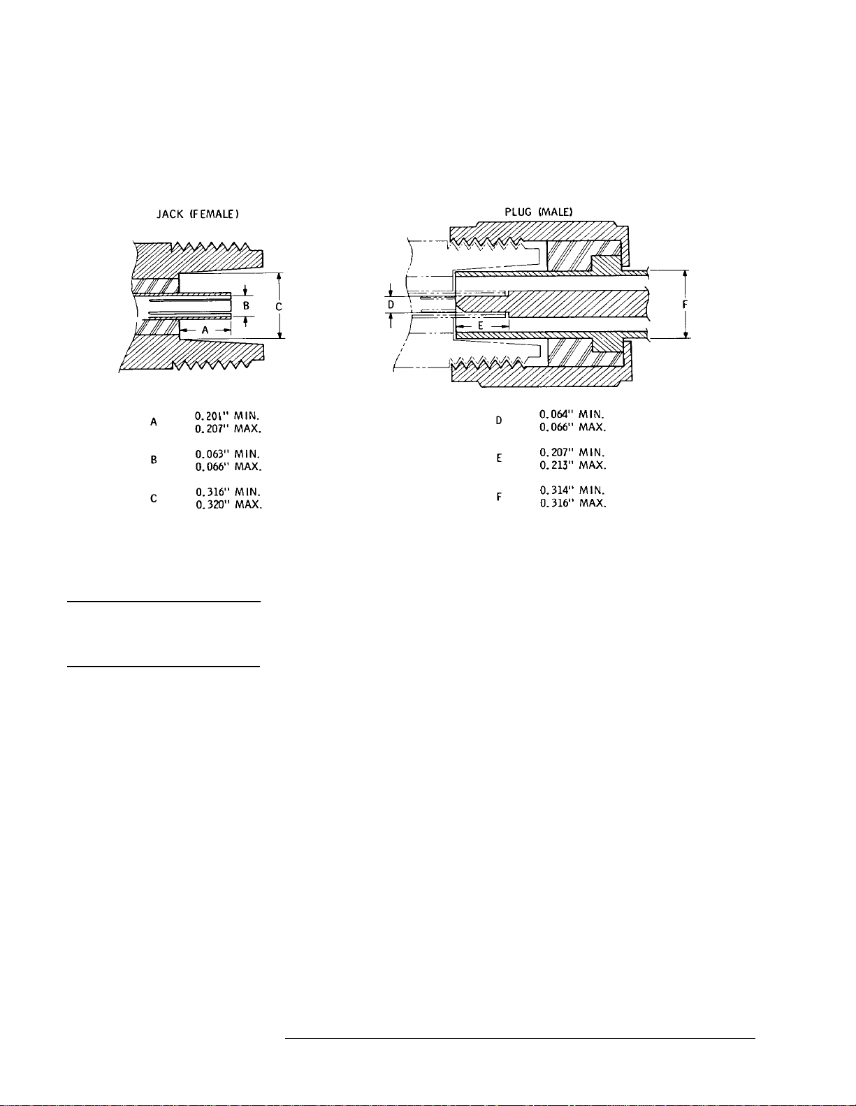
Connectors Type N connectors installed on 777D directional couplers with serial
numbers 3088 and abov e are st ainless steel fo r long wear and are compatible
with connectors whose dimensi ons conform to MIL-C- 39012 or MIL-C-71B
(see Figure 2).
Figure 2 Type N Connector Dimensions
CAUTION Do not mate with Type N male connectors with a pin diameter greater than
0.066 inches, as a discontinuity producing excess SWR will be formed and
large diameter male pins may damage the female connector.
Agilent 777D directio nal co uplers with s eria l number s 3087 an d below were
equipped with Type N male connectors with center pin diame ter greater t han
0.070 inches. Many of these couplers have been modified with new
connectors. However, check the dimensions of all male pins before mating
Type N connectors.
2 Agilent 777D Operating Note
Page 11

Specifications
Table 1 Specifications
Characteristic Value
Frequency Range 1.9 to 4.0 GHz
Primary Line Insertion Loss ≤0.75 dB
Minimum Directivity
Nominal Coupling Attenuation (each secondary arm) 20 dB
Accuracy of Coupling (each secondary arm) ± 0.5 dB
Specifications
1
30 dB
Maximum Coupling Variation (each secondary coupling
value)
Auxiliary Arm Tracking
Maximum Primary Line SWR
Maximum Secondary Line SWR 1.3
Maximum Power Handling Capacity 50 W cw or 10 kW peak
Primary Line Connectors
Secondary Line Connectors
Accessories Available Agilent 11511A Type N Female
Dimension 8-7/8 in. x 2-1/2 in. x 1-1/8 in
Net Weight 1.5 lb (700 g)
1. Measured with a sliding load.
2. 0.5 dB maximum change in coupling curve of one secondary arm relative to the other.
3. Connectors mate with all connectors whose dimensions conform to MIL-C-71B or MIL-C-39012
2
1
3
3
± 0.4 dB
Equal to or less than 0.5 dB
1.2
Agilent compatible Type N
connectors, one male and one
female
Agilent compatible Type N
connectors, female
Shorting Jack
Agilent 11512A Type N Male
Shorting Plug
(225 mm x 64 mm x 29 mm)
Agilent 777D Operating Note 3
Page 12

Inspection and Shipping
Inspection and Shipping
Initial Inspection Inspect the coupler for shipping damage as soon as it is unpacked. Check for
broken connectors; inspect surfaces for dents and scratches. Check electrical
performance using procedures in Performance Tests on page6. If the
coupler is damaged in any way, or fai ls to operate properl y, notify the carr ier
and your nearest Agilent Technologies Sales and Service Office. In the even t
of mechanical damage, the packing material and carton should be held for
carrier’s inspection. For assistance of any kind, including instruments under
warranty, contact the nearest Agilent Technologies Sales Office.
Repackaging for Shipment
Using Other Packaging
The same type containers and materials used in factory packaging can be
obtained through any Agilent Technologies office.
If the 777D is being returned to Agilen t Technologies for servicing, attach a
tag indicating the t ype of service re quired, retur n address, model number and
full serial number. Also, mark the container FRAGILE to assure careful
handling.
In any correspondence refer to the instrument by model number and full
serial number.
The following general instructions should be used when repackaging with
commercially available materials:
1. Wrap the 777D in heavy paper or plastic. (If shipping to an Agilent
Technologies service office or center, attach a tag indicating the type of
service required, the return address, model number and full serial
number.)
2. Use a strong shipping container. A double-wall carton made of 350
pound test material is adequate.
3. Use enough shock absorbing material (three to four inch layer) around
all sides of the instrument to provide firm cushion and prevent
movement inside the contai ner.
4. Seal the shipping container securely, and mark it FRAGILE to assure
careful handling.
5. In any correspondence re fers to the i nstrument by model numbe r and full
serial number.
4Agilent 777D Operating Note
Page 13
Reflectometer Application
Reflectometer Application
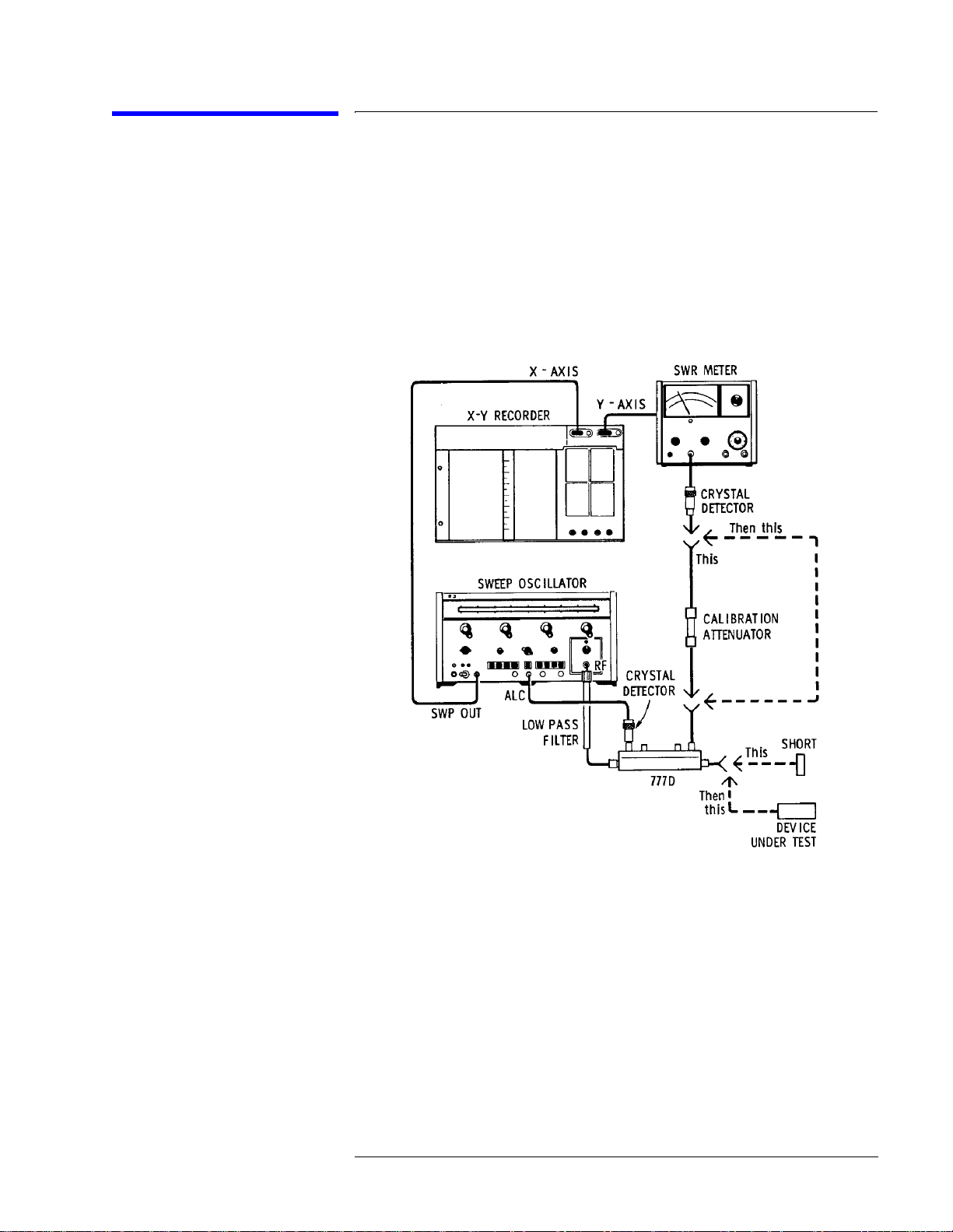
Description Figure 3 illustrates a typical setup for making reflectometer measurements.
The forward output, of the coupler is used for leveling the sweep oscillator.
The output of the reverse arm that is proportional to the reflections fr om the
device under test is displayed on an SWR meter. The device under test is
connected to the main line output of the coupler.
Equipment Considerations
Figure 3 Typical Reflectometer Setu p
The Agilent 423B crystal detectors are suitable for use as the detectors. A
SWR meter and oscilloscope are suitable for use as the calibrated display
instruments. If a permanent record of th e measurem ents is requi red, choose a
recorder that is suitable for use with the SWR meter.
Agilent 777D Operating Note 5
Page 14

Performance Tests
Perf ormance Tests
The procedures in t he foll ow tests f unctions check th e 777D performance f or
incoming inspection and periodic evaluation. The specifications in Table 1
on page 3 are the performance standards.
Test Equipment Required
The test instruments and accessories required to make the performance tests
are listed in Table 2. Test instruments can be used provided their
performance equals or exceeds the Critical Specifications listed.
Table 2 Recommended Test Equipment
Instrument Critical Specifications
Sweep Oscillator Frequency: 1.9 to 4.0 GHz
Residual FM: <3 kHz rms leveled output capability
Power output: ≥25 mW into 50 ohms
Amplitude Modulation: square-wave, 950 to 1050 Hz
10 dB Attenuator (2) Frequency Range: 1.9 to 4.0 GHz
Attenuation: 10 dB ±0.5 dB
SWR: ≤1.15
Connectors: APC-7*
Coaxial Short Type N male and Type N female
Short APC-7*
Sliding Load Frequency Range: 1.9 to 4.0 GHz
X-Y Recorder Range: Variable from 10 mV to 100 mV
Input Impedance: ≥100Κ ohms
Accuracy: ±3% of full scale
Network Analyzer & Harmonic
Frequency Converter
Polar Display Unit
Phase Gain Indicator
Reflection-Transmission Test Unit Frequency Range: 1.9 to 4.0 GHz
Flexible Arm Frequency Range: 1.9 to 4.0 GHz
Impedance: 50 ohms
Reflection Coefficient: ≤0.11
Connectors: APC-7*
Coaxial Termination (2) Frequency Range: 1.9 to 4.0 GHz
Impedance: 50 ohms
Reflection Coefficient: ≤0.05
Connectors: Type N male
6 Agilent 777D Operating Note
Page 15

Table 2 Recommended Test Equipment
Instrument Critical Specifications
Adapter (3) APC-7* to Type N
Frequency Range: 1.9 to 4.0 GHz
Impedance: 50 ohms
Reflection Coefficient: ≤0.03
Swivel Adapter (2) Frequency Range: 1.9 to 4.0 GHz
SWR: ≤1.2
Connectors: Must mate with APC-7
* Registered Trademark: Amphenol RF Division, Danbury, Connecticut
Performance Tests
Agilent 777D Operating Note 7
Page 16

Performance Tests
Directivity Test
Specification Minimum directivit y: 30 dB.
Description Refer to Figure 4 for test setup and Table 2 on page 6 for test equipment.
The 777D under test is c onnect ed as a refl ectomet er to the net wor k analy zer.
The system is calibrat ed with a coax ial shor t for a re fl ecti on coef ficient of 1.
The short is removed and the 777D is terminat ed with a sliding load. The
network analyzer test channel gain is increased by 30 dB making the
calibration of the p olar dis play’s outer graticul e cir cle e qual t o the di rectivity
specifica tion.
NOTE If the sliding load was a perfect termination, any energy from the coupler’s
reverse arm would be due only to th e directivity signal; however, the energy
from the coupler’s reverse arm, and thus the indi cation on the Polar Display,
is due to the directivity signal plus the reflection from the sliding load.
The Sweep Oscillator is set to sweep the frequency band of interest very
slowly. The sliding load is phased causi ng its ref lect ed ve ctor to r ota te about
the tip of the directi vity v ector . The center of the circle caus ed by phasing the
sliding load must be within the outer graticule circle.
Figure 4 Directivity Test Setup
8 Agilent 777D Operating Note
Page 17

Performance Tests
Equipment The directivity test equipment includes the following:
• Sweep oscillator
• Network analyzer
• Harmonic frequency converter
• Sliding load
• Coaxial short
• APC-7 to Type N adapter (2)
• Swivel adapter (2)
Procedure 1. Connect equipment as shown in Figure 4 with the 777D te rminated in a
coaxial sh ort.
2. Phase lock the network analyzer over the frequency band of interest.
3. Adjust the network analyzer test channel gain and amplitude vernier
controls to locate the trace on the outer graticule circle.
4. Remove the coaxial short and terminate the 777D with the sliding load.
5. Increase the network analyzer test channel gain by 30 dB.
6. Set the sweep oscillator to very slowly sweep the frequency range of
interest.
7. Phase the sliding load while observing the polar display. The center of
the circle caused by phasing the sliding load must be within the outer
graticule circle.
8. Repeat steps (1) through (9) at other frequencies to cover the 777D
operating range. Reverse the 777D and test the other coupled arm.
Agilent 777D Operating Note 9
Page 18

Coupling Attenuation and Coupling Variatio n Test
Specification Coupling attenuation: 20 dB ±0.5 dB
Description Refer to Figure 5 for test setup and Table 2 on page 6 for test equipment.
Performance Tests
Maximum coupling variation: ±0.4 dB
The equipment shown in Figure 5 is calibrated for a tr ansmission
measurement with the Flex ible Arm, Attenuators, and APC-7 Adapters
connected in a through path. The Network Analyzer test channel gain and
amplitude vernier controls are adjusted for a zero dB mete r indication at the
lowest frequency of .the band to be swept. The X-Y Recorder Y axis
sensitivity is adjusted so that 0.2 dB equals approximately one inch with
zero dB at the center. Calibration lines are dr awn in 0.2 dB increments to
±0.8 dB by adjusting the Network Analyzer amplitude vernier control. The
777D coupled arm is inserted in the test setup. The Network Analyzer test
channel gain is increased 20 dB and the coupling response is drawn on the
X-Y recorder. Coupling attenuation and coupling variation are determined
from the X-Y Recorder graph.
Figure 5 Coupling test and Primary Line Insertion Loss Test Setup
10 Agilent 777D Operating Note
Page 19

Performance Tests
Equipment • Sweep Oscillator
• Reflection-Transmission Test Unit
• Network Analyzer
• Harmonic Frequency Converter
• X-Y Recorder
• Flexible Arm
• 10 dB Attenuator (2)
• Coaxial Termination
• APC-7 to Type N Adapter (2)
Procedure 1. Connect equipment as shown in Figure 5 with the flexible arm,
attenuators, and APC-7 to Type N adapters connected in a
through-transmission path.
2. Phase lock the network analyzer over the frequency band of interest.
3. Adjust the network analyzer test channel gain and amplitude vernier
controls for a zero dB 841 3A meter indic ation at th e lo west fr equenc y of
the band to be swept.
4. Adjust the X-Y recorder’s Y axis sensitivity so that 0.2 dB (10 mV)
equals approximately one inch with zero dB at the center.
5. Record calibration lines in 0.2 dB increments to ±0.8 dB by adjusting
the network an alyzer amplit ude vernier control. Return the amplitude
vernier control to the zero dB setting.
6. Insert the 777D coupled arm in the setup.
7. Increase the network analyzer test channel gain 20 dB. The zero dB
calibration line now equals 20 dB.
8. Record the 777D coupling response. Determine the minimum and
maximum points on this trace in dB.
9. Coupling attenuation (mean coupling) = Maximum + Minimum/2 and
must be 20 dB ± 0.5 dB.
10. Coupling variation = Maximum – Minimum/2 and must be
≤0.4 dB.
Agilent 777D Operating Note 11
Page 20

Primary Line Insertion Loss Test
Specification ≤0.75 dB.
Description Refer to Figure 5 on page 10 for test setup and Table 2 on page 6 for test
Performance Tests
equipment.
The equipment shown in Figure 5 is calibrated for a tr ansmission
measurement with the flexible arm, attenuators, and APC-7 to Type N
adapters connected in a through path. The network analyzer test channel
gain and amplitude vernier controls are adjusted for a zero dB 8413A meter
indication at the lo west freq uency of the band to be swep t. The X-Y record er
Y axis sensitivity is adjusted so that 0.2 dB equals approximately one inch
with zero dB in the upper portion of the graph. A zero dB calibration line is
drawn and a calibration line at -0.75 dB is drawn by adjusting the Network
Analyzer amplitude v erni er con trol. The 777D pr imary l ine is inser ted i n the
setup (secondary line connectors terminated). A test trace is drawn on the
X-Y Recorder. The test trace must be within the two calibration traces.
Procedure 1. Connect equipment as shown in Figure 5 on page 10 with flexible arm,
attenuators, and APC-7 to Type N adapters connected in a through
transmission path.
2. Phase lock the network analyzer over the frequency band of interest.
3. Adjust the network analyzer test channel gain and amplitude vernier
controls for a zero dB meter indication at the lowest frequency of the
band to be swept.
4. Adjust the X-Y recorder Y axis se nsiti vit y so that 0.2 dB (10 mV) equa ls
approximately one inch with zero dB in the upper portion of the graph.
5. Record a zero dB calibration line. Adjust the network analyzer
amplitude vernier control for a –0.75 dB meter indication and record the
–0.75 dB calibration line. Return th e network analyzer ampli tude v ernier
control to the zero dB setting.
6. Insert the 777D primary line in the setup.
7. Record the insertion loss test trace. The test trace must be within the two
calibration lines.
12 Agilent 777D Operating Note
Page 21

Performance Tests
Primary and Secondary Line SWR
Specification Maximum Primary Line SWR: ≤1.2
Maximum Secondary Line SWR:
NOTE The SWR and directivity characteristics of the 777D are interdependent;
therefore, a satisfactory directivity check should indicate satisfactory SWR.
Description Refer to Figure 6 on page 14 for test setup and Table 2 on page 6 for test
equipment.
SWR is measured using a network analyzer, polar display unit, and test set.
The test setup is calibrated for a reflection coefficient of 1. Gain is inserted
in the test channel to obtain the appropriate full scale calibration for the
777D connector being measured. A swept frequency measurement of the
777D connector is made, which includes the ambiguity due to directivity of
the 8743A test set. If the sum of 777D connector SWR and test set
directivity exceeds 1.22 for secondary line connectors or 1.12 for primary
line connectors, single frequency measurements are made with test set
directivity calibrated out. Main line connector SWR is measured at single
frequencies with both test set directivity calibrated out and with the main
line termination reflection calibrated out.
≤1.3
Agilent 777D Operating Note 13
Page 22

Performance Tests
.
Figure 6 SWR Test Setup
Equipment • Sweep oscillator
• Reflection-transmission test unit
• Network analyzer
• Harmonic frequency converter
• Coaxial short
• Coaxial termination
• APC-7 to Type N adapter (2)
Procedure To calibrate the equipment
1. Connect equipment as shown in Figure 6 with appropriate adapter and
coaxial short connected to the unknown port.
2. Phase lock the Network Analyzer over the desired frequency band.
3. Push and hold the beam CTR push-button and adjust the horizontal and
vertical position controls to place the dot in the center of the graticule.
4. Obtain equal reference and test channel electrical lengths by adjusting
the line stretcher to collapse the trace to a dot or small est cluster.
14 Agilent 777D Operating Note
Page 23

Performance Tests
5. Adjust the network analyzer phase vernier, test channel gain and
amplitude vernier controls to place th e dot or cluster for a reference
indication of
6. For primary line connectors, increase the networ k analyzer test channel
gain by 25 dB. The network analyzer is now calibrated for a full-scale
reflection coefficient of 0.058 (SWR = 1.12). For secondary line
connectors increase the network analyzer test channel gain by 20 dB.
The network analyzer is now calibrated for a full-scale reflection
coefficient of 0.1 (SWR = 1.22).
r = 1 <180 degrees.
To perform a measurement
1. For swept frequency measurements, proceed as follows:
a. Remove the coaxial short and connec t 777D connecto r to the test set
UNKNOWN port. The displayed trace (combination of 777D SWR
and test set dir ect ivity) should be within the outer graticule circle. If
the displayed trace is outside the outer graticule circle at any
frequency, make single frequency measurements with test set
directivity calibrated out as follows:
2. For single frequency measurements with test set directivity calibrated
out, proceed as follows:
a. Set the sweep oscillator to the desired single frequency.
b. Remove the 777D under test and connect a sliding load to the
appropriate adapter on the test set UNKNOWN port.
c. Slide the load and adjust the network analyzer horizontal and
vertical position controls until the circle rotates about the center of
the CRT.
d. Remove the sliding load and connect 777D connector to be
measured to the test set UNKNOWN port.
e. For the 777D secondary line connectors the display must be within
the outer graticule circle. For primary line connectors, calibrate out
termination reflection as follows:
3. For primary line connectors, perform step i and the following:
a. Terminate the 777D primary line with the sliding load.
b. Slide the load and with a grease pencil mark the center of the circle
on the display. The reflection coefficient represented by this mark
must be within the outer graticule circle.
Agilent 777D Operating Note 15
Page 24

Test Record
Test Record
Table 3 is a performance test record. This table may be used during the test
to record the test values obtained, and it provides a permanent record of the
test values for use at a later time during periodic evaluation.
Table 3 Performance Test Record
Model 777D Tested by _____________
Dual-Directional Coupler Date _________________
Serial Number
Directivity ≥30 DB
Incident Port
Reflected Port
Coupling Attenuation 20 dB ±0.5 dB
Incident Port
Reflected Port
Coupling Variation ≤ ± 0.4 dB
Incident Port
Reflected Port
Primary Line SWR ≤1.2
Input Port
Output Port
Secondary Line SWR ≤1.3
Incident Port
Reflected Port
Primary Line Insertion Loss ≤ ±0.75 dB _________________________
.
_________________________
_________________________
.
_________________________
_________________________
.
_________________________
_________________________
.
_________________________
_________________________
.
_________________________
_________________________
Although input power can be applied to either main line port, for this test
record the ports are identified as follows when holding the 777D so that the
name plate can be read:
Input Port = Main line port to the left
Output Port = Main line port to the right
Incident Port = Coupled port to the left
Reflected Port = Coupled port to the right
16 Agilent 777D Operating Note
 Loading...