

Page 1

User's Guide
HP 71910A Wide-Bandwidth
Surveillance Receiver
ABCDE
71910-90002
No.
art
P
HP
Printed
USA
in
Edition
December
1996
A.0.0
Page 2

Notice
The information contained in this do cument is sub ject to change without notice.
Hewlett-Packard makes no warrantyofany kind with regard to this material, including,
but not limited to, the implied warranties of merchantability and tness for a particular
purpose. Hewlett-Packard shall not be liable for errors contained herein or for incidental or
consequential damages in connection with the furnishing, performance, or use of this material.
Restricted Rights Legend.
Use, duplication, or disclosure by the U.S. Government is sub ject to restrictions as set forth
in subparagraph (c) (1) (ii) of the Rights in Technical Data and Computer Software clause
at DFARS 252.227-7013 for DOD agencies, and subparagraphs (c) (1) and (c) (2) of the
Commercial Computer Software Restricted Rights clause at FAR 52.227-19 for other agencies.
This instrument has been designed and tested in accordance with IEC Publication 348,
Requirements for Electronic Measuring Apparatus
, and has b een supplied in a safe condition.
Safety
The instruction do cumentation contains information and warnings whichmust be followed by
condition.
safe
a
in
the user
to ensure
safe op
eration
and
to
main
tain
instrumen
the
t
c
Copyright Hewlett-Packard Company 1994{1996
All Righ
ermission
p
oun
F
1400
Reserv
ts
is
taingro
Repro
ed.
prohibited,
arkw
P
e
v
duction,
except
Santa
,
y
a
adaptation,
allo
as
Rosa,
under
ed
w
CA
translation
or
cop
the
95403-1799,
yrigh
USA
without
ws.
la
t
prior
written
Page 3

Safety
WARNING
WARNING
CAUTION
WARNING
UTION
CA
No operator serviceable parts inside. Refer servicing to qualified personnel. To
prevent electrical shock, do not removecovers.
For continued protection against fire hazard, replace line fuse only with same
type and ratings (type 6.3A/250V). The use of other fuses or materials is
prohibited.
Always use the three-prong ac power cord supplied with this instrument.
Failure to ensure adequate earth grounding by not using this cord maycause
instrument damage.
This is a Safety Class 1 Product (provided with a protective earthing ground
incorporated in the power cord.) The mains plug shall only be inserted in a
socket outlet provided with a protective earth contact. Any interruption of the
the
make
ely to
protectiv
instrument
instrumen
This
Degree
2
conductor
e
dangerous.
t
IEC
per
outside
inside
or
Intentional interruption
and
for
664
designed
is
1010
of
in Installation
use
ectiv
resp
instrument
the
is prohibited.
.
ely
is lik
Category I
I
and
ollution
P
UTION
CA
WARNING
cabinet,
a
in
restricted.
e
b
maxim
the
atts
w
greater
is
t
um
dissipated
than
The
op
800
erating
tilation
en
V
ection
v
con
erature
temp
erature
temp
cabinet.
forced
then
Requiremen
and
to
in
(outside
the
of
total p
If the
ection
v
con
ts:
When
the
of
out
cabinet)
the
instrumen
dissipated
er
ow
ust
m
installing
instrumen
m
4
y
b
t
used.
e
b
ust
C
in
b
for
t
e
the
m
the
ust
less
ery
ev
cabinet
instrumen
not
than
100
If this instrument is not used as specified, the protection provided by the
equipment could be impaired. This instrument must be used in a normal
condition (in which all means for protection are intact) only.
the
bien
am
in the
atts,
w
t
iii
Page 4

Surveillance with the HP 71910A
The HP 71910A Wide-Bandwidth Surveillance Receiver provides b oth signal search and signal
collection capabilit y from 100 Hz to 26.5 GHz. It is optimized for surveillance and signal
monitoring applications. The HP 71910A can be op erated in either of the following two
instrument mo des:
Spectrum analyzer op eration for signal searches
Maximum resolution BW
::::::::::::: ::::::::::::::: ::::::::::::::: ::::::
Wide-bandwidth receiver operation for signal collection
IF BW
Note
receiv
The
digitizers,
:::::::::::::: ::::::::::::::: ::::::::::::::: :::::::::::::::
surv
ectrum
instruments.
er's
FFT
When y
sp
not
IF
ou use
ectrum analyzer
100
a
video
and
baseband
the
bandwidth
MHz
outputs
analyzers,
wide-bandwidth
maxim
the
mode
sp
examined
e
b
can
other
and
eillance
resolution
um
analyzer.
oscilloscopes,
y
b
er,
receiv
bandwidth
3 MHz
10 to 100 MHz
er
remem
demo
b
MHz;
3
is
dulators,
that
in
is
it
HP
71910A
Wide-Bandwidth
eillance Receiv
Surv
er
iv
Page 5

HP 71910A Option 011
When rst turned on, the wide-bandwidth surveillance receiver op erates as a spectrum
analyzer. This allows you to view signals across a large frequency range. Once you'velocated
a signal, switch to the xed-tuned receiver mo de to downconvert the signal.
The downconverted signal is available at the rear panel for pro cessing and analyzing by
external devices. The Option 011 version of the instrument is primarily used as a collection
MHz
3
vide
and
a
more
it
er;
receiv
maxim
um
complete sp
outputs
IF
limited
ery
v
has
eak detection
p
ectrum analyzer.)
are
ailable
v
a
at
ectrum
sp
analyzer
bandwidth. (Option
panel
rear
the
capabilit
013 adds
due
y
an HP
linear
to
70902A
detection
pro
to
receiv
In
standard
additional
cessing
pro
de,
mo
er
rear-panel
MHz
70
these
do
the
output
and
signals.
wncon
is
140
v
cen
MHz
erted
tered
IF
signal
at 321.4
signals
a
is
resp
vailable
MHz.
ely
ectiv
the
at
Option
Refer
.
instrumen
and
001
Chapter
to
t's
002
panel.
rear
instrumen
examples
for
3
ts
The
pro
vide
of
v
Page 6

Demodulated outputs are available at the front panel
The front-panel
VIDEO
connector provides AM and pulse demodulation. Option 004 provides
additional I/Q outputs and Option 005 provides an additional FM output. Refer to Chapter 3
for examples of processing these signals.
a
vide
pro
de),
mo
XY
in
h
v
ery
e
8PSK,
as
oset
dicult.
this
16
frequency
in
spinning
QAM,
But,
ecause
b
mo
and
et
b
emen
v
w
64
een
QAM.
the
of
can
t
the
e
b
instrumen
enien
v
er and
004
ypical
t
metho
t
receiv
the
Option
con
With
receiv
wide-bandwidth
p
the
to
ed
w
slo
d
signal.
surv
t
oin
ts
iden
of
ers,
eillance
where
(together
tifying
constellations
the
mak
This
receiv
almost
is
it
with
dulation
mo
format
es
er's
external
an
\spin"
iden
frequency
Hz
1
stopped.
oscilloscop
formats
due to
tication
suc
the
tuning,
256 QAM Constellation Display
ed on Oscilloscope
vi
Page 7

Switch between operating mode with the press of a button
NNNNNNNNNNNNNNNNNNNNNNN
Press
4
5
Press
USER
4
MENU
and then
5
for use as a spectrum analyzer.
RX_MODE
for use as a wide-bandwidth surveillance receiver.
This is the default state when the instrument is rst turned on.
Press
4
DISPLAY
5
to access functions for controlling the display.
You will seldom need to use this key.For information on functions accessed with this key,
refer to the
Press
4
INSTR
HP 70004A DISPLAYOperating Manual
5
to switchbetween multiple instrument windows.
.
Multiple instrument windows must rst be congured as shown in Chapter 3.
vii
Page 8

Changing measurement parameters is easy
Use the front-panel knob, step keys, or numeric keypad to enter new measurements settings.
For example, press the
the setting, pressing the
4
CENTER
4
HOLD
5
key to change the displayed center frequency. After changing
5
key disables the keypad, knob, and step keys until another
function is selected.
Use the
45
(backspace) key to speed your navigation through softkey menus. When pressed,
the previous softkey menu is displayed. Also, use this key to backspace over numbers entered
using the data-entry keypad.
Conventions
The following key conventions are used in this guide:
4
Front-panel key
NNNNNNNNNNNNNNNNNNNNNNN
Softkey
5
Text shown like this represents a key physically located on the receiver.
Text shown like this represents a softkey. (The softkeys are located next to
the softkey labels, and the softkey lab els are the annotation on the rightor
left side of the spectrum analyzer display.)
Screen Text
Text
prin
ted
in
this
indicates
eface
yp
t
text
instrumen
the
on
ed
y
displa
t's
screen.
viii
Page 9

Instrument Markings
L
The instruction documentation symbol. The product is marked with this symbol when
it is necessary for the user to refer to the instructions in the do cumentation.
\CE" The CE mark is a registered trademark of the European Community. (If accompanied
byayear, it is when the design was proven.)
\ISM1-A" This is a symbol of an Industrial Scientic and Medical Group 1 Class A product.
\CSA" The CSA mark is a registered trademark of the Canadian Standards Asso ciation.
CAUTION
Caution
denotes a hazard. It calls attention to a pro cedure that, if not
correctly performed or adhered to, could result in damage to or destruction of
the instrument. Do not pro ceed beyond a
caution
note until the indicated
conditions are fully understoo d and met.
WARNING
Warning
correctly
not
understood
denotes a hazard. It calls attention to a procedure which, if not
loss
or
injury
in
result
note
could
until
the
indicated
conditions
performed or
proceed
bey
and
ond
met.
adhered to,
warning
a
of
life.
are
Do
fully
ix
Page 10

Assistance
Product maintenance agreements and other customer assistance agreements are available for
Hewlett-Packard products. For any assistance, contact your nearest Hewlett-Packard Sales
and Service Oce.
Regulatory Information
Regulatory information is lo cated in Chapter 5, \Specications and Characteristics."
Certification
Hewlett-Packard Company certies that this product met its published sp ecications at the
time of shipment from the factory. Hewlett-Packard further certies that its calibration
measurements are traceable to the United States National Institute of Standards and
Technology, to the extent allowed by the Institute's calibration facility, and to the calibration
facilities of other International Standards Organization members.
x
Page 11

Warranty
This Hewlett-Packard instrument product is warranted against defects in material and
workmanship for a perio d of one year from date of shipment. During the warranty perio d,
Hewlett-Packard Company will, at its option, either repair or replace pro ducts whichproveto
be defective.
For warranty service or repair, this product must b e returned to a service facility designated
by Hewlett-Packard. Buyer shall prepay shipping charges to Hewlett-Packard and
Hewlett-Packard shall pay shipping charges to return the product to Buyer. However, Buyer
shall pay all shipping charges, duties, and taxes for pro ducts returned to Hewlett-Packard
from another country.
Hewlett-Packard warrants that its software and rmware designated by Hewlett-Packard for
use with an instrument will execute its programming instructions when prop erly installed on
that instrument. Hewlett-Packard do es not warrant that the operation of the instrument, or
software, or rmware will be uninterrupted or error-free.
Limitation of Warranty
inadequate
or
pro
MER
er
duct,
CKARD
A
CHANT
dication or
improp
or
ABILITY
er
foregoing
The
eration
op
b
tenance
main
misuse,
site preparation
NO
OTHER
W
SPECIFICALL
FITNESS
AND
y
t
arran
w
er,
Buy
y
outside
main
or
ARRANTY
DISCLAIMS
Y
AP
OR
F
not
shall
er-supplied
Buy
the en
of
tenance.
IS
TICULAR
AR
defects
to
apply
w
soft
vironmental
EXPRESSED
IMPLIED
THE
PURPOSE.
resulting
are or
interfacing,
ecications
sp
IMPLIED.
OR
ARRANTIES
W
improp
from
unauthorized mo
the
for
HEWLETT-P
OF
clusive
Ex
REMEDIES PR
THE
REMEDIES.
INDIRECT,
BASED
Remedies
HEWLETT-P
SPECIAL,
ON CONTRA
VIDED
O
A
INCIDENT
CT, TOR
HEREIN
CKARD
AL,
T, OR
BUYER'S
ARE
SHALL
OR
NOT
CONSEQUENTIAL
ANY OTHER
LIABLE
BE
LEGAL
SOLE
AND
OR
F
AMA
D
THEOR
CLUSIVE
EX
ANY
GES,
Y.
DIRECT,
WHETHER
xi
Page 12

xii
Page 13

Contents
1. Getting Started
To install the receiver . . . . . . . . . . . . . . . . . . . . . . . . . 1-2
To install an Option 011 receiver . . . . . . . . . . . . . . . . . . . . 1-12
To install an HP 70911A into an HP 71209A . . . . . . . . . . . . . . . 1-14
To install an HP 70620B preamp . . . . . . . . . . . . . . . . . . . . 1-25
Maintaining the Receiver . . . . . . . . . . . . . . . . . . . . . . . 1-28
To clean the HP 70004A's screen . . . . . . . . . . . . . . . . . . . 1-28
Tochange the mainframe's fuse . . . . . . . . . . . . . . . . . . . . 1-28
Tochange the custom keypad . . . . . . . . . . . . . . . . . . . . 1-29
To lo cate a module's serial number . . . . . . . . . . . . . . . . . . 1-30
Reinstalling the
install
o
T
install
o
T
install
o
T
Returning
return a
o
T
System
2.
Op
3.
Calibrating
Searc
Collecting
V
erating
erform
p
o
T
erform
p
o
T
hing for
Locating Signals . . . . . . . . . . . . . . . . . . . . . . . . . . 3-5
Tochange the frequency range . . . . . . . . . . . . . . . . . . . 3-6
To return to full span . . . . . . . . . . . . . . . . . . . . . . . 3-7
Tochange the reference level and amplitude scale . . . . . . . . . . . 3-7
Tochange the amplitude units . . . . . . . . . . . . . . . . . . . 3-7
Using
Resolving Signals
Reducing Display
Controlling the Sw
Changing
Changing
Mark
view
o
T
To resolv
To reduce the displa
Tochange the sweep time . . . . . . . . . . . . . . . . . . . . . 3-12
To set continuous or single sweeps . . . . . . . . . . . . . . . . . . 3-12
hange
oc
T
Receiver
the
from
a
from
Option
an
in
Receiv
the
receiv
erication of
HP
the
calibration
a
calibration
a
Signals (sp
.
ers
signal
a
e closely spaced signals
ter-F
Cen
the
to
(receiv
Receiv
Signals
Personalit
memory
3.5-inc
71910A
ed Noise
cen
h
011
for
er
service
for
er
eration
Op
ectrum analyzer
. .
.
using
. . . . . . . . . . . . . . . . . . . . . . . . 3-10
. .
yed noise .
. . . . . . . . . . . . . . . . . . . . . . . . 3-12
eep
requency
frequency
ter
er
Mo
er
.
.
.
.
.
.
.
.
.
.
.
.
.
.
.
.
.
y .
. .
. .
. .
. .
.
.
.
.
.
.
.
.
.
.
card
disk
instrumen
Service
.
.
.
with HP
.
.
mark
. . . . . . . . . . . . . . . . . . . . . . 3-11
Step
de)
mo
de
.
e
driv
ette
t
.
.
.
.
.
.
.
.
.
.
.
.
.
.
.
.
.
70620B preamp
mo
.
.
.
.
.
.
.
.
ers
. . . . . . . . . .
. . . . . . . .
.
Size
size
step
.
.
.
.
.
.
.
.
.
.
.
. .
.
.
.
de)
.
. .
.
.
.
.
.
.
.
.
.
. .
.
.
.
.
.
.
.
.
. .
.
.
.
.
.
. .
.
. .
. .
.
.
.
.
.
.
.
.
.
.
.
.
.
. .
. .
.
.
.
.
.
.
.
.
.
.
.
.
.
.
.
.
.
.
.
.
.
.
.
.
.
.
. .
. .
.
.
.
.
.
.
.
.
.
.
.
.
.
.
.
.
.
.
. .
.
.
.
.
.
.
.
. .
. .
.
.
.
.
.
.
.
.
.
.
.
.
.
.
.
.
.
.
.
.
.
. .
.
.
. .
.
.
.
.
.
.
.
.
.
. . . . . . . . 3-10
. . . . . . . . . . . 3-11
.
.
.
.
.
.
.
.
.
.
.
.
.
.
.
.
.
.
.
.
.
.
.
.
.
.
.
. .
.
.
.
.
.
.
.
.
.
.
.
.
.
.
.
.
.
.
.
.
.
. 1-35
.
.
.
.
.
.
.
.
.
1-31
1-32
1-33
1-34
1-35
3-3
3-3
3-3
3-4
3-8
3-8
3-13
3-13
3-14
3-16
Contents-1
Page 14

To switchtoreceiver mode . . . . . . . . . . . . . . . . . . . . . 3-16
To select a new signal . . . . . . . . . . . . . . . . . . . . . . . 3-18
To return to spectrum analyzer mode . . . . . . . . . . . . . . . . 3-18
Selecting IF Outputs and Channel Filters . . . . . . . . . . . . . . . 3-19
To select an IF output . . . . . . . . . . . . . . . . . . . . . . . 3-22
To adjust the IF and video bandwidth . . . . . . . . . . . . . . . . 3-22
Tochange the IF-to-video bandwidth ratio . . . . . . . . . . . . . . 3-22
To increase the 321.4 MHz bandwidth (preselector bypass) . . . . . . . 3-23
To adjust the IF gain and RF attenuation . . . . . . . . . . . . . . 3-23
To select an Option 007 channel lter . . . . . . . . . . . . . . . . 3-23
Demodulating Signals . . . . . . . . . . . . . . . . . . . . . . . . 3-25
To demodulate the signal . . . . . . . . . . . . . . . . . . . . . 3-27
To adjust IQ gain, oset, and quadrature . . . . . . . . . . . . . . 3-27
Viewing the Signal's Average Amplitude Level . . . . . . . . . . . . . 3-28
To view the average amplitude . . . . . . . . . . . . . . . . . . . 3-28
Measurement Examples . . . . . . . . . . . . . . . . . . . . . . . 3-29
To search for and collect a pulsed RF signal . . . . . . . . . . . . . 3-29
Tocharacterize a wide-bandwidth FM signal . . . . . . . . . . . . . 3-34
3-38
.
.
.
.
.
.
.
.
.
. .
. .
. .
. .
.
.
.
.
.
.
.
.
.
.
.
.
.
.
.
.
.
.
.
.
.
.
.
.
.
. 3-46
.
.
.
.
.
.
.
.
.
.
.
.
.
.
.
.
.
.
. .
.
.
.
.
.
.
.
.
.
.
.
.
.
.
.
.
.
.
.
.
.
.
.
.
.
.
.
.
.
.
.
.
.
.
.
.
.
.
.
.
. .
.
.
.
.
.
.
.
.
.
.
.
.
.
.
. 3-55
.
.
.
.
.
.
.
.
.
.
.
.
.
. .
. .
. .
. .
.
.
.
. .
. .
. .
. .
.
.
.
.
.
.
.
. .
.
.
.
.
.
.
.
.
. .
.
.
.
. 3-67
.
.
.
.
.
.
.
.
.
.
. . . . . . . . . . 3-68
3-41
3-43
3-45
3-49
3-50
3-50
3-51
3-52
3-53
3-56
3-56
3-65
3-66
.
.
RF
.
.
er
.
.
yed
do
digital
.
.
.
.
er mo
.
.
.
.
mo
External
.
.
.
.
.
.
.
.
.
.
is
.
esn't
characterize
To
Collecting
ually
Man
ual
Using
T
Using
T
T
Extending
Con
T
T
T
To
To write a title on the screen . . . . . . . . . . . . . . . . . . . . . 3-57
BlockDiagrams . . . . . . . . . . . . . . . . . . . . . . . . . . . . 3-59
If You Have a Problem . . . . . . . . . . . . . . . . . . . . . . . . 3-62
If UNCOR is displayed . . . . . . . . . . . . . . . . . . . . . . . 3-63
If UNCAL and Usable RBW limited is displayed . . . . . . . . . . . . 3-64
If UNCAL
If
If
If there is a frequency shift
Man
man
o
T
o searc
Preamplier
a
the
use
o
turn
o
trolling
e
v
sa
o
recall or
o
view
o
blank
ossible
P
PREAMP
the
ually
for
h
HP
the
o
the
System
receiv
a
o
w
t
the
and
compression
a wide-bandwidth
Signals
.
de
Mo
collection receiv
ter
en
collect
and
.
.
70620B
preamp in
requency
F
Conguration
state
er
y
Usable
On
receiv
O
delete a
instrumen
displa
.
.
.
.
.
.
pulsed
a
.
.
.
.
preamp
receiv
Range
t
.
VBW
is
with
. .
. .
state
er
ws
windo
.
.
.
limited
displa
ey
softk
in an HP 70911A output
.
. .
signal
.
.
de
.
.
.
.
.
displa
.
w
.
.
.
.
.
.
.
.
.
.
ork
transmission
.
.
.
.
.
.
. .
.
.
.
de
.
.
.
.
.
.
.
.
.
. .
.
.
.
.
Mixers
.
.
.
.
.
.
.
.
.
.
.
.
.
.
.
.
.
.
.
.
.
ed
y
.
.
.
.
. .
.
Contents-2
Page 15

4. Programming
Getting Started . . . . . . . . . . . . . . . . . . . . . . . . . . . . 4-2
To connect the equipment . . . . . . . . . . . . . . . . . . . . . . 4-3
HP BASIC Programming Example . . . . . . . . . . . . . . . . . . . 4-4
Communicating with the Receiver . . . . . . . . . . . . . . . . . . . . 4-5
Initial Commands . . . . . . . . . . . . . . . . . . . . . . . . . . 4-5
Executing Remote Commands . . . . . . . . . . . . . . . . . . . . 4-5
Local and Remote Control . . . . . . . . . . . . . . . . . . . . . 4-6
Transfering Data to the Computer . . . . . . . . . . . . . . . . . . . 4-7
Monitoring System Op eration . . . . . . . . . . . . . . . . . . . . . 4-8
Interrupt Process . . . . . . . . . . . . . . . . . . . . . . . . . . 4-8
Receiver Status Byte . . . . . . . . . . . . . . . . . . . . . . . 4-8
The Service-Request Mask . . . . . . . . . . . . . . . . . . . . . 4-9
Monitoring System Operation without Using Service Requests . . . . . . 4-10
5. Specications and Characteristics
Denitions of Terms . . . . . . . . . . . . . . . . . . . . . . . . . . 5-2
HP 71910A Collection Receiver Specications . . . . . . . . . . . . . . 5-3
.
.
. .
. .
. .
.
.
.
.
.
.
. .
.
. .
.
.
. .
.
.
.
.
.
.
.
.
.
.
.
.
.
. .
.
.
.
.
.
.
.
.
.
.
.
.
.
.
. .
. .
.
.
.
.
.
.
.
.
.
.
.
.
.
. .
. .
.
.
.
.
.
.
.
71910A
HP
General
ysical Dimensions
Ph
Regulatory
Notice
Searc
ecications
Sp
Information
German
for
Receiv
h
er
.
.
of Mainframes
.
Noise
y:
ecications
Sp
. .
.
.
.
.
.
.
.
Declaration
. .
.
.
.
.
.
.
5-9
5-15
5-16
5-17
5-18
Men
6.
Dictionary
7.
Alphab
Maps
u
Reference
N
1.25
N
N
N
N
N
N
N
N
N
N
N
N
NN
N
MHz
5
N
N
N
N
N
N
NN
NN
N
N
N
N
N
MHz
10
NN
NN
NN
N
N
N
N
N
N
N
N
N
20 MHz
NNNNNNNNNNNNNNNNNNNN
36 MHz
NNNNNNNNNNNNNNNNNNNN
70 MHz
70 MHz OUT . . . . . . . . . . . . . . . . . . . . . . . . . . . 7-2
140 MHz OUT . . . . . . . . . . . . . . . . . . . . . . . . . . . 7-2
MHz
300
MHz
300
321.4 MHz IN
321.4 MHz OPT IN .
321.4 MHz OPT OUT .
321.4 MHz OUT
NNNNNNNNNNNNNNNNNNNNNNNNN
NNNNNNN
70911 OPTIONS
45
. . . . . . . . . . . . . . . . . . . . . . . . . . . . . . . . 7-3
485495
.
415
N
N
N
N
N
NN
N
N
N
N
N
N
N
N
UNITS
A
N
N
N
N
N
N
N
N
.
AM
N
N
N
N
N
N
N
N
N
N
N
N
N
N
N
BYPASS
.
MHz
N
N
.
.
.
N
N
N
N
N
.
.
N
N
N
NN
. .
. . . . . . . . . . . . . . . . . . . . . . . . . . . . . . 7-2
. . . . . . . . . . . . . . . . . . . . . . . . . . . . . . 7-2
IN
OUT
. . . . . . . . . . . . . . . . . . . . . . . . . . . . . . . 7-4
.
.
.
N
N
N
N
N
N
N
N
N
N
N
N
N
N
N
N
N
AutoMan
.
. .
N
N
N
N
N
.
.
Listing
etical
N
N
N
N
N
N
N
N
N
N
N
N
N
N
N
N
N
N
N
N
N
N
N
NN
.
. .
. .
.
.
.
.
.
.
.
.
.
.
.
.
.
. .
. .
.
.
.
.
.
.
. .
.
.
.
.
.
.
.
.
.
.
.
.
.
.
.
.
.
.
.
.
.
.
.
.
.
.
.
. .
.
.
.
.
.
.
.
.
.
.
.
.
.
.
.
.
.
. .
.
. . . .
. . . . . . . . . . . . . . . . .
NNNNNNNNN
. . . . . .
.
.
.
N
N
N
N
N
N
N
N
N
N
N
N
NN
N
.
.
.
.
.
.
. . . . . . . . . . . . . . . . . . . . . . . 7-3
. . . . . . . . . . . . . . .
. . . . . . . . . . . . . . . . . . . . . 7-3
. .
. . . . . . . . . . . . . . . . . . . . 7-3
. .
.
.
.
.
.
.
.
.
.
.
.
.
.
.
.
.
.
.
.
.
.
.
.
.
.
.
.
.
.
.
.
.
.
.
. .
.
.
.
. .
.
.
.
.
.
.
.
.
.
.
.
.
.
.
.
.
.
.
.
.
.
.
.
.
.
.
.
.
.
.
.
.
.
.
.
.
.
.
.
.
.
.
.
.
. .
. .
.
.
.
. .
. .
. .
. .
.
.
.
.
.
.
.
.
. .
.
.
.
.
.
.
.
. 7-3
.
.
.
.
.
.
.
.
.
.
. .
.
. . . . . . . . . 7-3
. . . . . . . . . 7-3
.
.
.
.
.
.
.
.
.
.
.
.
.
.
.
.
.
.
.
.
. .
.
.
.
.
.
.
.
.
.
.
. .
.
.
.
.
.
.
.
.
.
.
.
.
.
.
.
.
.
.
.
.
.
.
.
.
.
.
.
.
.
.
.
.
.
.
.
.
.
.
. .
.
.
.
.
.
.
.
7-2
7-2
7-2
7-2
7-2
7-3
7-4
7-4
7-4
7-4
Contents-3
Page 16

NNNNNNN
N
BW
. . . . . . . . . . . . . . . . . . . . . . . . . . . . . . . . 7-4
4
CENTER
NNNNNNNNNNNNNNNNNNNN
CENTER
NNNNNNNNNNNNNNNNNNNNNNNNNNNNNNNNNNNNNNNNNNNNNNN
CF STEP AutoMan
NNNNNNNNNNNNNNNNNNNNNNNNNNNNNNNNNNNNNNNNNNNNNNN
channel filters
NNNNNNNNNNN
dBm
NNNNNNNNNNNNNN
dBmV
NNNNNNNNNNNNNN
dBuV
NNNNNNNNNNNNNNNNNNNNNNNNNNNNNNNNNNNNNN
DEL RX STATE
NNNNNNNNNNNNNNNNN
Demod
NNNNNNNNNNNNNNNNNNNNNNNNNNNNNNNNNNNNNNNNNNNN
DISPLAY On Off
FM . . . . . . . . . . . . . . . . . . . . . . . . . . . . . . . . 7-6
NNNNNNNNNNNNNNNNN
FM NB
NNNNNNNNNNNNNNNNN
FM WB
NNNNNNNNNNNNNN
Freq
N
N
N
N
FULL
N
N
N
N
Gain
N
N
N
N
Help
4
HOLD
N
N
N
N
HP-MSIB
N
N
N
N
HPIB
I
N
N
N
N
I
N
N
N
N
I
N
N
N
N
IF
NN
N
N
N
IF
4
INSTR
4
INSTR PRESET
NNNNNNNNNNNNNNNNNNNNNNNNNNNNNNNNNNNNNNNNN
INTRNL MEMORY
NNNNNNNN
IQ
NNNNNNNNNNNNNNNNNNNNNNNNNNNNNNNN
LAST STATE
4
MENU
N
N
N
N
Misc
N
N
N
N
NARROW SPAN
NB VID IN
4
NEXT PEAK
4
NORMAL
4
PEAK SEARCH
4
PLOT
NNNNNNNNNNNNNNNNNNNNNNNNNNNNNNNNNNNNNNNNN
PREAMP On Off
N
N
N
N
PRESEL
4
PRINT
N
N
N
N
PULSE
5
. . . . . . . . . . . . . . . . . . . . . . . . . . . . . . 7-4
. . . . . . . . . . . . . . . . . . . . . . . . . . . . . . 7-5
. . . . . . . . . . . . . . . . . . . . . . . . . 7-5
. . . . . . . . . . . . . . . . . . . . . . . . . 7-5
. . . . . . . . . . . . . . . . . . . . . . . . . . . . . . . . 7-5
. . . . . . . . . . . . . . . . . . . . . . . . . . . . . . . 7-5
. . . . . . . . . . . . . . . . . . . . . . . . . . . . . . . 7-5
. . . . . . . . . . . . . . . . . . . . . . . . . . . 7-5
. . . . . . . . . . . . . . . . . . . . . . . . . . . . . . . 7-5
. . . . . . . . . . . . . . . . . . . . . . . . . . 7-6
. . . . . . . . . . . . . . . . . . . . . . . . . . . . . . . 7-6
. . . . . . . . . . . . . . . . . . . . . . . . . . . . . . . 7-6
. . . . . . . . . . . . . . . . . . . . . . . . . . . . . . . 7-6
N
N
N
N
N
N
N
N
N
N
N
N
N
N
N
N
N
N
N
N
N
N
N
N
N
SPAN
NN
NN
NN
N
N
N
N
N
N
N
NN
NN
N
N
N
N
5
N
N
N
N
N
N
N
N
N
N
N
N
N
N
N
N
N
N
N
N
N
N
.
.
N
N
N
N
N
N
N
N
N
N
N
GAIN
N
N
N
N
N
N
N
N
N
N
N
OFFSET
N
N
N
N
N
N
NN
NN
N
BW
N
N
N
N
N
N
N
N
NN
GAIN
5
. . . . . . . . . . . . . . . . . . . . . . . . . . . . . . . . 7-10
5
N
N
NN
N
N
N
N
N
N
N
N
N
N
N
N
N
N
N
NN
5
N
N
N
N
N
N
N
N
N
N
N
5
N
N
N
N
N
N
N
N
N
N
N
.
. .
N
N
N
N
N
N
N
N
N
N
N
N
N
N
N
N
N
Off
On
.
.
.
N
N
N
N
N
N
N
N
N
N
N
N
N
NN
N
N
CARD
N
N
N
N
NN
N
N
N
N
N
N
N
N
DISK
.
.
.
NN
N
N
N
.
.
NN
N
N
N
N
N
N
N
N
N
.
N
N
.
.
.
NN
NN
N
N
N
N
N
N
N
N
N
N
N
N
N
AutoMan
.
.
.
.
.
.
.
.
.
N
NN
N
N
N
N
N
N
N
N
N
N
NN
N
N
5
5
. . . . . . . . .
5
. . . . . . . . . . . . . . . . . . . . . . . . . . . . . . . 7-11
N
N
N
N
N
N
N
N
N
N
N
N
N
N
NN
N
Off
On
.
.
.
N
N
.
.
.
.
.
.
.
.
.
NN
N
.
.
.
.
.
N
N
N
N
N
N
.
.
.
.
.
.
.
.
. .
.
.
.
.
.
.
.
N
N
N
N
N
N
N
N
N
N
N
N
N
N
N
.
.
.
5
. . . . . . . . . . . . . . . . . . . . . . . . . . . 7-9
. . . . . . . . . . . . . . . . . . . . . . . . . . 7-10
. . . . . . . . . . .
.
.
.
.
.
.
N
N
N
. .
. . . . . .
. . . . . . . . . . . . . . . . . . . . .
. . . . . . . . . . . . . . . . . . . . .
. . . . . . . . . . . . . . . . . . . . . . . . . . 7-11
N
N
N
N
N
N
N
N
N
. .
.
.
.
.
.
.
.
.
.
.
.
.
.
.
.
.
.
.
.
. .
.
.
.
.
.
.
.
.
.
.
.
.
.
.
.
.
.
.
. .
.
.
.
.
.
.
.
. . . . . . . . . . . . . . . . . . . . . . . . .
.
.
.
.
.
.
.
.
.
.
.
.
.
.
.
.
.
.
.
.
.
.
.
. .
.
.
.
. .
.
.
.
. .
.
.
.
.
.
.
.
.
. .
. .
.
. .
.
. .
. . . . . . . . . . . . . . . . . . . . . . 7-10
. . . . . . . . . . . . . . . . . . . . . 7-11
.
.
.
.
.
.
. .
.
.
.
.
.
.
.
.
.
.
. .
.
.
.
.
.
.
.
.
.
.
.
.
.
. .
.
.
.
.
.
.
. .
. . . . . . . . . . . . . . . . . 7-10
.
.
.
.
.
.
.
.
.
.
.
.
.
.
.
. .
.
.
.
.
.
.
.
. .
.
.
.
.
.
.
.
.
.
. .
.
.
.
.
.
. .
.
.
.
.
.
.
. .
.
.
.
.
.
.
.
. .
.
.
.
.
.
.
.
.
.
.
.
.
.
.
. .
.
.
.
.
.
.
. .
. .
.
.
.
.
.
.
.
.
.
.
.
.
.
.
.
.
.
.
.
.
.
.
. .
.
.
.
.
.
.
. .
. .
. .
.
.
.
.
.
.
.
.
.
. .
.
.
.
.
.
. .
. .
.
.
.
.
.
.
.
.
.
.
.
.
.
.
.
.
.
.
.
.
.
.
. .
.
.
.
.
. .
.
.
. . . . . . . 7-11
. . . . . . . 7-11
.
.
.
.
. .
.
.
.
.
. .
.
.
.
.
.
.
.
.
.
.
.
.
.
.
.
.
.
.
.
.
.
.
.
.
.
.
.
.
.
.
.
.
.
.
.
.
.
.
.
.
.
.
.
.
.
.
.
.
.
.
.
.
.
.
.
.
.
.
.
.
.
.
. .
.
.
.
.
.
.
.
.
.
.
.
.
.
.
.
.
.
.
.
.
.
.
.
.
.
.
.
.
.
.
.
.
. 7-11
.
.
7-6
7-7
7-7
7-7
7-7
7-7
7-8
7-8
7-8
7-8
7-9
7-9
7-10
7-10
7-10
7-12
7-12
Contents-4
Page 17

Q. . . . . . . . . . . . . . . . . . . . . . . . . . . . . . . . . 7-12
NNNNNNNNNNNNNNNNNNNN
QGAIN
NNNNNNNNNNNNNNNNNNNNNNNNNN
Q OFFSET
NNNNNNNNNNNNNNNNNNNNNNNNNNNNNNNN
QUADRATURE
NNNNNNNNNNNNNNNNNNNNNNNNNNNNNNNNNNNNNN
RCL RX STATE
4
RECALL
NNNNNNNNNNNNNNNNNNNNNNNNNNNNNNNNNNNNNNNNNNNNNNN
RECEIVR VERSION
4
REF LEVEL
NNNNNNNNNNNNNNNNNNNNNNNNNNNNNNNNNNNNNNNNN
Return to S/A
NNNNNNNNNNNNNNNNNNNNNNNNNNNNNNNNNNNNNNNNNNNNNNN
RF ATTN AutoMan
RF/IF Gain: . . . . . . . . . . . . . . . . . . . . . . . . . . . . 7-14
NNNNNNNNNNNNNNNNNNNNNNNNNNNNNNNNNNNNNNNNN
save & recall
NNNNNNNNNNNNNNNNNNNNNNNNNNNNNNNNNNNNNNNNN
SAVE RX STATE
NNNNNNNNNNNNNNNNNNNNNNNNNNNNNNNNNNNNNNNNNNNN
SIG LVL On Off
4
SIGNAL TRACK
4
SPAN
N
N
N
N
N
N
N
N
N
SPAN
4
ART
ST
4
STOP
N
N
N
N
N
N
N
N
N
temp
N
N
N
N
N
N
N
N
N
TITLE
N
N
N
N
N
N
N
N
N
units
4
USER
N
N
NN
N
N
N
N
N
VBW/IFB
N
N
N
N
NN
N
N
N
VID
VID OUT
VIDEO
N
N
N
N
NN
NN
N
VOLT
N
N
N
N
N
N
NN
N
WATT
WB VID IN . . . . . . . . . . . . . . . . . . . . . . . . . . . . 7-18
WB VID OUT . . . . . . . . . . . . . . . . . . . . . . . . . . . 7-18
. . . . . . . . . . . . . . . . . . . . . . . . . . . . . . 7-12
. . . . . . . . . . . . . . . . . . . . . . . . . . . . . 7-13
. . . . . . . . . . . . . . . . . . . . . . . . . . . . 7-13
. . . . . . . . . . . . . . . . . . . . . . . . . . . 7-13
5
. . . . . . . . . . . . . . . . . . . . . . . . . . . . . . 7-13
. . . . . . . . . . . . . . . . . . . . . . . . . 7-14
5
. . . . . . . . . . . . . . . . . . . . . . . . . . . . . 7-14
. . . . . . . . . . . . . . . . . . . . . . . . . . 7-14
. . . . . . . . . . . . . . . . . . . . . . . . . 7-14
. . . . . . . . . . . . . . . . . . . . . . . . . . 7-15
. . . . . . . . . . . . . . . . . . . . . . . . . . 7-15
. . . . . . . . . . . . . . . . . . . . . . . . . . 7-15
5
. . . . . . . . . . . . . . . . . . . . . . . . . . . 7-16
5
. . . . . . . . . . . . . . . . . . . . . . . . . . . . . . . 7-16
N
N
N
N
N
.
FREQ
FREQ
NN
NN
N
N
N
N
N
N
N
N
compens
N
N
N
N
N
N
N
N
.
N
N
N
N
N
N
N
N
N
N
N
N
menu
.
5
N
N
N
N
N
N
N
N
N
N
N
N
N
N
N
N
N
N
N
N
N
N
N
N
BW
N
N
N
N
N
.
N
N
N
N
N
. . . . . . . . . . . . . . . . . . . . . . . . . . . . . . . 7-18
. .
. .
. .
5
.
5
N
N
N
N
N
N
N
N
N
N
N
N
N
N
N
N
. .
.
.
N
N
N
N
N
N
N
NN
N
N
.
.
.
.
N
N
N
N
N
NN
N
N
N
N
N
N
N
N
N
RATIO
N
N
N
N
N
N
N
NN
N
N
N
N
N
N
N
AutoMan
TO L.O.
.
.
.
.
.
.
.
N
.
.
. .
N
N
N
N
N
N
N
N
N
N
N
.
.
. .
. .
.
.
.
.
.
.
.
.
.
. .
.
.
.
.
.
.
.
.
. .
.
.
.
.
.
.
.
.
.
.
.
.
. .
.
.
.
.
.
.
.
. .
.
.
.
.
.
.
.
.
.
.
.
.
.
.
. .
.
.
.
.
.
.
.
.
.
.
.
.
.
.
.
.
.
. .
.
.
.
.
.
.
.
.
.
.
. .
.
.
.
.
.
.
.
.
.
.
.
.
.
.
.
.
.
.
.
.
.
.
. .
.
.
.
.
.
.
.
.
.
.
.
.
.
.
.
.
.
.
.
.
.
.
.
.
. .
.
.
.
.
.
. .
.
.
.
.
.
.
.
.
.
.
.
.
. .
.
.
.
. .
.
.
.
.
.
. .
.
.
.
.
.
.
.
.
. .
.
. .
.
.
.
. .
.
.
.
.
.
.
.
.
.
.
.
.
.
.
.
.
. .
.
.
.
.
.
.
.
.
.
.
.
.
.
. .
.
.
.
.
.
.
.
.
.
.
. .
.
. .
.
.
.
.
.
.
.
.
.
.
.
.
.
.
.
.
.
.
.
.
.
. .
.
.
.
.
.
.
.
.
. .
. .
.
.
. .
.
.
.
.
.
.
.
.
.
. .
.
.
. .
.
.
. 7-16
. 7-16
.
.
.
.
.
.
.
.
7-16
7-16
7-17
7-17
7-17
7-17
7-17
7-17
7-17
7-18
8. Programming Commands
.
.
. .
.
.
.
.
.
.
.
.
.
.
. .
.
.
.
.
.
.
.
.
tions
en
Conv
tax
Syn
ersus
V
eys
Softk
RXRMT CHANFIL
RXRMT CHANP
RXRMT DELETERX .
RXRMT DEMOD
RXRMT FMOFF .
RXRMT IFGAIN . . . . . . . . . . . . . . . . . . . . . . . . . . . 8-15
RXRMT IGAIN . . . . . . . . . . . . . . . . . . . . . . . . . . . 8-16
RXRMT
RXRMT
RXRMT
RXRMT
INIT
IOFFSET
OPTIONS?
QGAIN
.
.
.
.
.
.
.
.
.
. .
.
.
Commands
T . . . . . . . . . . . . . . . . . . . .
ATH .
. . . . . . . . .
. . . . . . . . . . . . . . . . . . . . .
.
.
.
.
.
.
.
.
. .
.
. . . . . .
. . . . . . . . . . . . . . . . . . . .
.
.
.
.
.
.
.
.
.
.
.
.
.
.
.
.
. . . . . . . . . . . . . . . . . . 8-8
. . . . . . . . . . . . . . . . . 8-11
.
.
.
.
.
.
.
.
.
.
.
.
.
. .
.
.
.
.
.
.
.
.
.
.
.
.
.
.
. .
.
.
.
.
.
.
.
.
.
.
.
.
.
.
.
.
.
. .
.
.
. . . . . 8-6
. . . . 8-10
. . . . . 8-13
.
.
.
.
.
. .
.
.
.
.
.
.
.
.
.
.
.
.
.
.
.
.
.
. .
.
.
.
.
.
.
.
Contents-5
.
.
.
.
.
8-2
8-4
8-17
8-18
8-19
8-20
Page 18

RXRMT QOFFSET . . . . . . . . . . . . . . . . . . . . . . . . . 8-21
RXRMT QUAD . . . . . . . . . . . . . . . . . . . . . . . . . . . 8-22
RXRMT RECALLRX . . . . . . . . . . . . . . . . . . . . . . . . . 8-24
RXRMT SAVERX . . . . . . . . . . . . . . . . . . . . . . . . . . 8-25
RXRMT TEMPCOMP . . . . . . . . . . . . . . . . . . . . . . . . 8-26
RXRMT VERSION? . . . . . . . . . . . . . . . . . . . . . . . . . 8-27
9. Error Messages
Error Message Descriptions . . . . . . . . . . . . . . . . . . . . . . 9-2
Troublesho oting Features . . . . . . . . . . . . . . . . . . . . . . . 9-6
10. Tables and Charts
11. Conguring and Addressing
Modular Measurement System Terms . . . . . . . . . . . . . . . . . . 11-2
Functional Terms . . . . . . . . . . . . . . . . . . . . . . . . . . 11-2
Element . . . . . . . . . . . . . . . . . . . . . . . . . . . . . 11-2
Master . . . . . . . . . . . . . . . . . . . . . . . . . . . . . 11-2
.
.
.
.
.
.
.
.
.
.
.
.
.
.
.
.
.
.
.
.
.
.
.
.
.
.
.
.
t
t.
erms
T
.
Proto
Matrix
onse
Elemen
Criteria .
.
.
.
. .
. .
. .
. .
.
.
.
.
.
.
.
.
.
.
.
.
. .
. .
. .
. .
.
elemen
.
.
ts
lo
RF
precision
or
t
.
.
.
.
.
.
.
.
.
.
.
.
.
.
.
. .
.
.
.
.
.
.
.
.
.
.
.
.
.
.
.
.
.
.
.
. .
.
.
.
.
.
.
.
.
.
.
.
.
.
.
.
.
.
.
.
.
.
.
.
.
. .
.
.
.
.
.
.
.
.
.
.
.
.
.
.
.
t
. .
.
.
.
.
.
.
.
.
.
.
.
.
.
.
col
.
.
.
.
.
.
. .
.
.
.
.
.
.
.
.
.
.
. .
. .
.
.
.
.
.
.
.
Area
.
.
ts
.
ts
cal
. . . . . . . . . . . . . . . . . . . .
trac
HP
.
. .
.
.
.
.
.
.
.
.
.
Congured
for
.
.
oscillator
. . . . .
king
trac
e
v
a
w
frequency
70620B
.
.
.
.
.
.
.
.
.
.
. .
.
.
.
.
.
.
.
.
.
.
.
.
. .
. .
. .
.
.
.
.
.
.
.
.
.
. .
. .
. .
. .
.
.
.
. .
.
.
.
.
. .
.
.
.
Systems
.
.
. .
.
.
.
.
. . . . . . . . . . . . . 11-10
.
.
.
.
.
.
.
.
.
.
.
.
.
.
.
70000
HP
.
.
.
.
.
source
. . . . . . . . . . . . . . . .
. . . .
generator
king
preampliers
.
. . . . . . . . . . . . . . . . . . 11-10
. . . . . . . . . . . . . . . . . . 11-10
generator
reference
.
.
.
. .
.
.
.
.
.
.
.
.
.
.
.
.
.
.
.
.
.
.
.
.
.
.
.
.
.
.
.
.
.
.
.
. .
. .
.
.
.
.
.
.
.
.
.
.
. .
.
.
.
.
.
.
.
.
.
.
.
.
.
.
.
.
.
.
.
.
.
.
.
.
.
.
.
.
.
.
.
.
.
.
.
.
.
.
.
.
.
.
.
.
.
.
.
.
.
.
.
.
.
.
.
.
. .
. .
.
.
.
.
.
.
.
.
.
.
. .
.
.
.
.
.
.
.
.
.
.
.
.
.
.
. .
.
.
.
.
.
.
.
.
.
.
. .
.
.
.
.
. . . . . . 11-9
. . . . . . . 11-10
.
.
.
.
.
.
.
.
.
.
.
.
.
.
.
.
.
.
.
.
.
.
.
.
.
.
.
.
.
. .
.
Sub-master
e
v
Sla
enden
Indep
Instrumen
Structural
Mainframe
dule
Mo
Stand-Alone Instrumen
Address
Address
Displa
HP-IB
Addressing Elemen
Master
Sub-Master
Slave Elements . . . . . . . . . . . . . . . . . . . . . . . . . . . 11-7
Slave Area Boundaries . . . . . . . . . . . . . . . . . . . . . . . . 11-7
Independent Elements . . . . . . . . . . . . . . . . . . . . . . . . 11-8
Addressing Order Requirements . . . . . . . . . . . . . . . . . . . . 11-9
Default
Addressing
Map
y-Resp
Access
Elemen
Addressing
70900B
HP
HP 70902A IF section .
HP 70700A digitizer .
HP 70911A ultra-wide bandwidth IF section
HP 70903A IF section .
HP 70907B .
RF section . . . . . . . . . . . . . . . . . . . . . . . . . . . . 11-10
HP 70600A preselector/HP 70601A preselector . . . . . . . . . . . . 11-10
70300A
HP
70301A micro
HP
70310A
HP
70621A
HP
11-2
.
11-2
.
11-2
.
11-2
11-2
.
11-2
.
11-2
.
11-3
.
11-4
.
11-4
.
11-5
.
11-5
.
11-6
.
11-6
.
11-6
.
11-9
.
. 11-9
11-9
.
11-10
.
11-10
.
11-10
.
11-10
.
Contents-6
Page 19

Row Addressing Priority . . . . . . . . . . . . . . . . . . . . . . . 11-11
Address Switches . . . . . . . . . . . . . . . . . . . . . . . . . . . 11-12
Master Address Switches . . . . . . . . . . . . . . . . . . . . . . . 11-12
HP-IB ON/OFF . . . . . . . . . . . . . . . . . . . . . . . . . 11-13
SW1/MEM . . . . . . . . . . . . . . . . . . . . . . . . . . . 11-13
MAS/SLA . . . . . . . . . . . . . . . . . . . . . . . . . . . . 11-13
NRML/TEST . . . . . . . . . . . . . . . . . . . . . . . . . . 11-13
COLUMNs 1|5 . . . . . . . . . . . . . . . . . . . . . . . . . 11-13
ROWs 1|3 . . . . . . . . . . . . . . . . . . . . . . . . . . . 11-13
Slave Address Switches . . . . . . . . . . . . . . . . . . . . . . . 11-14
Rows 1|3 . . . . . . . . . . . . . . . . . . . . . . . . . . . . 11-14
Columns 1|5 . . . . . . . . . . . . . . . . . . . . . . . . . . 11-14
Display Address Switches . . . . . . . . . . . . . . . . . . . . . . 11-14
HP-IB ON/OFF . . . . . . . . . . . . . . . . . . . . . . . . . 11-14
A1|A5 . . . . . . . . . . . . . . . . . . . . . . . . . . . . . 11-14
TALK ONLY. . . . . . . . . . . . . . . . . . . . . . . . . . . 11-15
SYSTEM CONTROLLER . . . . . . . . . . . . . . . . . . . . . 11-15
TEST MODE . . . . . . . . . . . . . . . . . . . . . . . . . . 11-15
Index
Contents-7
Page 20

Tables
10-1. Hewlett-Packard Sales and Service Oces . . . . . . . . . . . . . . . 10-4
Contents-8
Page 21

1
Getting Started
This chapter shows you how to install and maintain the HP 71910A and its various options.
In addition, there is a procedure for installing an HP 70911A wide bandwidth IF module into
an existing HP 71209A Option 001 spectrum analyzer.
No sp ecial tools are required except for the pro cedure \To install an HP 70911A in your
HP 71209A." This procedure requires an 8 mm ball driver. Be careful to observe all notes,
cautions, and warnings in the pro cedures.
Contents
To install the receiver
o install
T
install
o
T
install
o
T
Main
T
T
T
T
Reinstalling
T
To
T
Returning the Receiver for Service
To return a receiver for service
Note
an Option
an
an
taining
the
clean
o
hange
c
o
hange
c
o
cate a
lo
o
install
o
install from
install
o
HP
HP
the
HP
the
the
mo
Receiv
the
from
an
in
The following installation procedure applies to both the HP 71910A wide
bandwidth
surv
replaces
:::::::::::::: ::::::::::::::: ::::::::::::::: ::::::::::::::: :::::::
receiv
011
to
70911A
70620B
Receiv
mainframe's
custom
dule's
the
a 3.5-inc
Option
eillance
in
preamp
er
:
70004A's
eypad
k
serial
ersonalit
P
er
memory
h
011
surv
receiv
HP
the
::
::
:
:
:
:
:
:
:
:
:
:
:
:
:
:
:
:
:
::
::
::
::
:
:
:
:
:
:
:
:
:
:
:
:
:
:
er
::
:
:
:
:
:
:
:
:
:
:
:
:
:
:
:
:
:
::
::
::
::
:
:
:
:
:
:
:
:
:
:
:
:
:
:
:
:
:
:
e
t
\P"
::
:
:
:
:
:
:
:
:
:
:
:
:
:
:
:
:
:
:
:
:
:
:
::
:
:
:
:
:
:
:
:
:
:
:
:
er
system,
display
:
::
:
:
:
:
::
:
:
:
:
::
:
:
:
:
:
:
and
:
:
::
:
:
:
:
:
:
:
:
:
:
:
:
:
:
:
:
:
:
:
:
:
:
:
:
:
:
:
:
::
:
:
the HP
.
:
::
::
:
:
:
:
:
:
:
:
:
:
:
:
:
:
:
:
:
:
:
:
:
:
:
:
:
:
:
:
:
:
:
:
:
:
:
:
:
:
:
:
::
:
:
:
:
:
:
:
:
:
:
:
:
:
:
:
:
:
:
:
::
:
:
:
:
:
:
::
:
:
:
:
:
:
:
:
:
:
:
:
:
:
:
:
:
:
:
:
:
:
:
:
:
:
:
:
:
:
:
::
:
:
:
:
:
:
:
:
:
:
:
:
:
:
:
:
:
:
:
:
:
:
:
:
:
:
:
::
:
:
:
:
:
::
::
:
:
:
:
:
:
:
:
:
:
:
:
:
:
:
:
:
:
:
:
:
:
:
:
:
:
:
:
::
::
:
:
:
:
:
:
:
:
:
:
:
:
:
:
:
:
:
:
:
:
:
:
::
::
::
::
:
:
:
:
::
:
:
:
:
:
:
:
:
:
:
:
:
:
:
:
:
:
::
::
::
bandwidth
wide
70207A
PC Displa
the
71910P
HP
71209A
HP
an
:
:
:
:
:
:
:
:
:
:
:
:
:
:
:
:
:
:
:
screen
fuse
n
disk
eillance
70004A
:
:
:
:
:
:
:
::
:
:
:
er
b
um
:
:
y
::
::
card
driv
ette
instrumen
::::::::::::: ::::::::::::::: :::::::::::::: ::::::::::
::::::::::::: ::::::::::::::: ::::::::::::::: ::::::::::
receiv
a
In
er.
color
::
:
:
:
:
:
:
::
:
:
:
:
:
:
:
::
::
:
:
:
:
:
:
:
:
::
::
:
:
:
:
:
1-2
1-12
:
:
:
:
:
:
:
::
1-14
:
:
:
:
:
::
::
1-25
:
:
:
:
:
:
:
:
:
:
1-28
:
:
:
:
:
:
:
:
1-28
:
:
:
:
:
:
:
::
:
1-28
:
:
:
:
:
:
:
:
:
1-29
::
:
:
:
:
:
:
:
1-30
:
:
:
:
:
:
::
:
:
1-31
:
:
:
:
:
:
:
:
:
:
1-32
:
:
:
:
:
:
:
:
:
1-33
::
::
::
:
:
1-34
:
:
:
:
:
::
::
1-35
1-35
MMS
for
y
the \P" and \A" systems, only
There are no sp ecication c
module placemen
Refer to the
the HP 70207A PC Display for MMS, the MSIB interface card, and the MSIB
Y-cable that is used with a \P" system.
t and rear-panel cabling are dieren
HP 70207A
hanges b et
User's Guide
ween
t.
for complete installation instructions of
Getting
Started
1-1
Page 22

To install the receiver
1. Inspect the shipping container or cushioning material for damage.
If there is damage or a defect, savethepacking materials, le a claim with the carrier,
then contact the nearest Hewlett-Packard sales and service oce for immediate repair
or replacement.
2. Make sure the instrument's line-voltage selectors are set to the same voltage as the power
source.
UTION
CA
Note
ARNING
W
cause
y
in-line
isolation
is
blo
the
oltage
v
wn
fuse)
Before
the
to
damage
Option
turning
correct
(a
400 instrumen
isolation transformer
instrumen
the
for
the
to
ts for
use
for
on, b
t
w
o
p
system
400 Hz
with
sure
e
source.
er
when
operation
HP
the
LINE
the
ailure
F
p
the
come
70001A
VOLTAGE
do
to
cable
er
w
o
with
mainframe.
this
an
is
external
SELECTOR
ma
plugged in.
The
transformer protects the user from shock hazard. The in-line isolation
transformer must be removed for 60 Hz p ower-source operation. Failure to
remove the in-line transformer may result in a blown fuse. The HP 70004A
display/mainframe does not require an option to op erate on 400 Hz.
ailure
F
the
not operate
Do
attached
in-line
Hz
400
a
isolation
option
transformer
receiv
for
the
HP
400
a
on
er
follow this precaution can result in personal injury
without
line
wer
po
Hz
70001A mainframe.
.
set
to
1-2
Getting
Started
Page 23

3. If you're installing a standard HP 71910A, connect the rear-panel cables as shown in the
following gure:
Rear-Panel Connections for the Standard HP 71910A
Getting
Started
1-3
Page 24

4. If you're installing an HP 71910A that has an option, connect the rear-panel cables as
shown in the following gure:
1-4
Getting
Rear-Panel Connections for the HP 71910A with Options
Started
Page 25

5. If you're installing a standard HP 71910P, connect the rear-panel cables as shown in the
following gure:
71910P
Rear-P
Connections
anel
for
the
Standard
HP
Getting
Started
1-5
Page 26

6. If you're installing a standard HP 71910P with two mainframes and an HP 70902A
IF section added, connect the rear-panel cables as shown in the following gure:
1-6
Rear-Panel Connections for the Standard HP 71910P with Two Mainframes and an
HP 70902A IF Section Added
Getting
Started
Page 27

7. If you're installing a standard HP 71910P with two mainframes and an HP 70620B
preamplier added, connect the rear-panel cables as shown in the following gure:
Rear-Panel Connections for the Standard HP 71910P with Two Mainframes and an
HP 70620B Preamplifier Added
Getting
Started
1-7
Page 28

8. If you're connecting the MSIB cables on an HP 71910A, connect the MSIB cables as
shown in the following gure:
Color
MSIB
OUT
connector
Connect
a.
and the
MSIB
Cabling
MSIB cable
an
70001A
HP
the
from
bet
mainframe's
HP
w
70001A
the
een
MSIB
Mainframe
70004A
HP
connector
IN
the
to
color
.
HP
displa
70004A
y's
y
Displa
b. Connect an MSIB cable b etween the HP 70001A mainframe's MSIB OUT connector
and the HP 70004A color display's MSIB IN connector.
The MSIB cables are connected serially, coupling the input of one elementtothe
output of the next until the loop is completed.
1-8
Getting
Started
Page 29

9. If you're connecting the MSIB Y-Cable on an HP 71910P, connect the cables as shown in
the following gure:
CAUTION
Care should b e taken when connecting the MSIB Y-cable to the
MSIB interface card. Damage can occur if the MSIB Y-cable connection is
not prop erly aligned. Ensure p ower is not applied while making or removing
connections.
a. Remove the protective cap from the MSIB Y-cable and inspect the pins for damage or
misalignment.
Do not install MSIB Y-cable if pins are bent or damaged.
service from Hewlett-Packard. Refer to \Returning the Receiver for Service".
b. Align the MSIB Y-cable to the MSIB interface card's MSIB connector (1).
Do not force the connectors together!
(See the ab ove caution.)
c. Tighten the captive-screws on the MSIB Y-cable to the MSIB interface card.
Do not over tighten the screws!
d. Connect the two free-ends of the MSIB Y-cable (that are not connected to the
MSIB
OUT
and
the
displa
IN
input
.
y
of
one
HP
70001A
MSIB
The MSIB
the output
Connect
e.
terface
in
the ac
card
cables are
next un
of the
line cord
70001A
HP
the
to
)
connected serially
op
lo
til a
computer
our
y
to
mainframe's
, coupling
completed.
is
and
If necessary, obtain
.
connectors
(2)
mainframe
to
Note
Refer to the
70207A
HP
the
Y-cable.
HP 70207A User's Guide
for MMS
y
Displa
PC
for complete installation instructions of
MSIB
the
and
,
,
the
MSIB
terface
in
card
Getting
Started
1-9
Page 30

10. Connect the power cables to both instrument mainframes rst, then plug the cables into
the p ower outlet.
11.
12.
13.
the
Set
tilation
ven
an
If
the45
Except
IF
the
HP
70004A
HP
LINE
on
sections
70001A
starts
fan
switc
IF
the
will
mainframe's
up.
displa
color
ON,
to
h
sections,
its
ve
ha
and
eac
ACT
y
h
4
b
is
listen
mo
ligh
LINE
5
eing
dule's
t
to
on.
switc
used
erify
v
fron
to
h
our
y
in
that the
t-panel
ON,
system
ACT
and
en
v
LED
listen to
h
(suc
tilation
should
v
as the
fan
erify
HP
starts
lit.
e
b
the
that
71910A),
up.
Only
one
set
of
14.
1-10
On
Getting
the
displa
Started
left-side
the
,
y
softk
gure
wing
follo
the
in
wn
sho
eys
should
b
ed.
y
displa
e
Page 31

If the receiver menu softkeys do not appear after power-up, the display window
steps:
wing
follo
probably
a. Press
displa
b.
Press
eration.
op
c. Press
receiv
is
the
.
y
the
the
er.
not
4
DISPLA
NN
NN
NEXT
4
MENU
assigned
Y
N
N
N
N
N
N
N
N
N
N
N
N
N
N
INSTR
5
5
N
N
k
N
N
N
ey
ey on
k
NN
NN
N
N
to
the receiv
to
the displa
N
N
N
softk
displa
ey
erform
t
softk
it, p
panel
is
er
eys
to
selected
for
o assign
er. T
fron
y's
receiv
the
til
un
en
sev
the
y
the
access
the
independen
for
stand-alone
main
op
men
t
eration
the
for
u
the
of
Getting
Started
1-11
Page 32
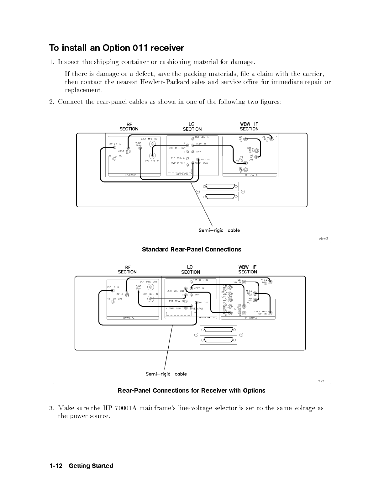
To install an Option 011 receiver
1. Inspect the shipping container or cushioning material for damage.
If there is damage or a defect, save the packing materials, le a claim with the carrier,
then contact the nearest Hewlett-Packard sales and service oce for immediate repair or
replacement.
2. Connect the rear-panel cables as shown in one of the following two gures:
Connections
Standard
Rear-Panel Connections for Receiv
3. Make sure the HP 70001A mainframe's line-voltage selector is set to the same voltage as
the power source.
Rear-P
anel
er with Options
1-12
Getting
Started
Page 33

CAUTION
Before turning the instrument on, be sure the
LINE VOLTAGE SELECTOR
is set
to the correct voltage for the power source. Failure to do this maycause
damage (a blown fuse) to the system when the power cable is plugged in.
400
for
instrumen
not
w
w
er
v
e
this
cable
400
the
operate
transformer
protects
ust
m
in-line
a
in-line
precaution
the
to
Note
ARNING
W
Connect
4.
w
o
p
er
the
outlet.
Option
isolation
transformer
transformer
remo
Do
attached
follo
o
p
5. Set the HP 70001A mainframe's45LINE
ts
for use
the
remo
e
b
transformer
Hz
400
isolation
can
HP
with the
user
ed
v
option
transformer
result
70001A
switch to ON, and listen to verify that the
ventilation fan starts up.
6. Check to see that each mo dule's front-panel
operation
Hz
sho
from
Hz
60
for
result in
y
ma
receiv
for the
personal
in
mainframe
ACT
LED lights.
HP
c
er
70001A
hazard.
k
w
o
p
on
injury
rst,
come with
er-source
wn
blo
a
400 Hz
a
70001A
HP
.
then plug
an external
mainframe.
in-line
The
operation.
fuse.
er
w
po
mainframe.
the cable
The
isolation
without
line
in-line
isolation
ailure
F
ailure
F
into
to
the
to
the
Getting
Started
1-13
Page 34

To install an HP 70911A into an HP 71209A
This procedure shows you how to install an HP 70911A mo dule into an already existing HP
71209A Option 001 spectrum analyzer. Option 001 spectrum analyzers have an HP 70910A
wide-bandwidth RF mo dule instead of the standard HP 70909A RF mo dule.
Older HP 71209A Option 001 spectrum analyzers may need to be modied b efore you can
install the HP 70911A ultra-wide bandwidth section which includes options. This is explained
in the following paragraphs.
HP 70001A mainframe upgrade
If the HP 70001A mainframe has a serial number of 3327A05741 or earlier, an upgrade kit
must be installed that increases the power and airow capability. The serial number is located
by opening the HP 70001A's front-panel door to exp ose the hex-lo ck screws that are used for
installing mo dules. The serial number lab el is lo cated behind this door on the inside of the
right frame section.
WARNING
70900B
HP
70900B
HP
The
Press
Press
Press
Press
memory
4
MENU
the
N
N
MORE
N
N
ROM VERSION
MByte
1.
2.
3.
4.
In order to provide proper cooling for the HP 70911A module which includes
number
serial
a
e
v
ha
serial
hav
date
must
and
e
number
service
that do
rm
de,
co
are
w
do
3327A05741
is
for
office
not include
follo
or
wing
940120
the
or
information
option
and
later
steps:
L
NN
NN
NN
NN
N
N
N
N
N
N
N
N
O
5
left-side
N
N
N
N
N
NN
NN
N
N
options,
the
3327A05741.
local
our
y
upgrade
an
require
the retrofit
upgrade
oscillator
cal
lo
option.
.
To
N
N
N
N
N
N
N
N
N
N
N
Misc
NN
NN
NN
NN
N
N
N
N
N
N
N
N
N
N
N
N
1
N
N
N
N
NN
of
N
N
and
3
N
N
N
N
N
N
N
N
N
N
N
70001A
HP
the
If
Hewlett-P
HP
kit.
mo
the
view
N
N
N
softk
ey
N
then
mainframe
70001A
HP
ackard
70911A
kit.
m
dule
rm
.
N
N
N
N
N
N
N
N
NN
NN
NN
NN
N
service
sales
modules
ust
are
w
N
N
N
N
N
.
.
higher
belo
cards
include
than
w,
installing
on
will
contact
not
the
1
When upgrading an existing HP 71209A Option 001, order the HP 70911A Option 099 or
098 to obtain the LO rmware and memory upgrade. An HP 71910A system already includes
these items. To determine which option (098 or 099) is required, do the following steps:
4
Press
1.
2.
3.
4.
Press
Press
Press
the
NNNNNNNNNNNNNNNNNNNNNNNN
NNNNNNNNNNNNNNNNNN
5. Find the
6. If the en
.
5
MENU
left-side
N
N
State
NNNNNNNNNNN
MORE 1 of 4
NNNNNNNNNNNNNNNNNNNN
EXTEND STATE
CPU:
heading
try reads
68000
N
N
N
N
N
N
N
N
N
NN
N
N
N
N
softk
NNNNNNNNNNNNNNNNNNNNNNNN
,
MORE 2 of 4
.
ey
NNNNNNNNNNN
, and then
NNNNNNNNNNNNNNNNNNNNNNNN
NNNNNNNNNNN
show states
.
that is displa
yed on the screen.
, the HP 70911A Option 098 is required. If the
.
entry reads
68020
the HP 70911A Option 099 is required.
,
1-14
Getting
Started
Page 35

HP 70910A RF section upgrade
The HP 71910A includes an HP 70910A RF section with rmware enhancements for
moderately faster tuning than older HP 70910A RF sections. HP 70910A's with serial number
3409A00170 and later include this newer rmware. The newer rmware is not necessary for
proper operation. Contact an HP service center for upgrade information.
Tools needed
Install the mo dule requires one of the following drivers:
8 mm hex-ball driver
8 mm hex-ball driver
(long)
(short)
::::::::::: ::::::::::::::: ::::::::::
:::::::::: ::::::::::::::: ::::::::::
HP part number 8710-1307
HP part number 8710-1651
Antistatic precautions
Electrical components are easily damaged by small amounts of static electricity. If possible,
work at a static-free work station.
Procedure
damage.
1.
2. T
3.
4.
ect
Insp
there
If
then
replacemen
or
on
urn
Press
the
urn
T
address
the
con
y
4
DISPLA
fron
map
shipping
damage
is
tact
HP
our
5
Y
t-panel
should
tainer
con
defect,
a
or
nearest Hewlett-P
the
t.
knob
ok
lo
Option
the
to
lik
71209A
and
then
or
left-side
scroll
the
e
cushioning
ethe
v
sa
ard
ack
ectrum
sp
001
N
NN
N
N
N
N
N
N
N
Address
address
the
displa
one
material
packing
sales
N
N
N
N
N
N
N
N
N
N
N
N
N
N
ed
y
N
N
Map
map
in
for
materials, le
service
and
analyzer.
N
NN
N
N
N
N
N
N
the
softk
so
follo
ey
that
.
the
wing
a claim
oce
mo
gure.
with
immediate
for
dules
are
the
sho
carrier,
repair
wn.
The
The
HP
ou
y
MMS
70911A
HP
70903A
need
y
ma
addressing,
and
to c
has
HP
hange
refer
default
a
70902A
the
Chapter
to
Address Map of HP 71209A
whic
3,18
the
the
The
of
ab
HP
follo
gure.
ve
o
70911A
wing
gure
MMS
dules
mo
address
address
in
of
11.
.
places
h
If
or
F
this
a
sho
b
it
space
general
the
ws
Getting
een
w
et
una
is
discussion
address
Started
the
ailable,
v
switc
of
hes
1-15
Page 36

on the HP 70911A module. The switches are set to the default MMS address of ROW3
and COLUMN 18.
5. Turn o the ac line power to the HP 71209A, and removethe two line-p ower cords from
the mainframes.
1-16
Getting
Started
Page 37

6. Open the HP 70001A mainframe's front-panel door to expose the hex-lock screw.
unlo
to
kwise
c
terclo
coun
olts
b
k
c
in
hex-lo
the
follo
wing
gure.
7.
Using
remo
e
v
mm hex-ball
an 8
t
the
w
o
blank
driver,
panels
turn the
wn
sho
and
k
c
8. Install the new HP 70911A mo dule next to the HP 70310A.
Getting
Started
1-17
Page 38

1-18
Getting
Started
Page 39

9. If you're installing a standard HP 70911A mo dule, connect the rear-panel cables as shown
in the following gure.
Note
Rear-Panel Connections for Standard Configuration
If you have an HP 71910P conguration, refer to the section, \To install the
hapter.
c
this
receiv
er",
whic
h
is
cated at
lo
the
eginning
b
of
Getting
Started
1-19
Page 40

10. If you're installing an Option 001/002 HP 70911A mo dule, connect the rear-panel cables
as shown in the following gure.
1-20
Getting
Rear-Panel Connections for Option 001/002
Started
Page 41

11. Connect the power cables to both instrument mainframes rst, then plug the cables into
the p ower outlet.
12.
13.
14.
15.
70001A mainframe's
HP
the
Set
HP
LINE
to see
ERR
fan
70004A
switc
that
only
LED
4
DISPLAY
tilation
en
v
an
If
the45
Check
system,
the
an
If
a. Press
b.
Press the left-side
starts
color
to
h
eac
the
remains
5
.
up.
is
y
displa
listen
and
ON,
dule's
mo
h
selected
is
that
one
k
hec
c
on,
NNNNNNNNNNNNNNNNNNNNNNNNNNNNNNNNNNN
Address Map
4
5
eing
b
fron
LINE
used
to v
t-panel
switc
erify
will
the address
softkey.
to ON,
h
our
y
in
that
ACT
e
v
ha
map as
system (suc
the
ligh
LED
ACT
its
described
and
en
v
tilation
ts.
ligh
listen
h
When
on.
t
in the
as
to
fan
the
t
w
HP
starts
IF
o
follo
sections
wing
that
erify
v
c. Turn the front-panel knob to scroll the address map so that it lo oks similar the one
is
dules
mo
the
the
\b
of
follo
elo
wing
w"
gure. F
HP
the
70903A
in
wn
sho
addresses
W
O
R
70911A
HP
the
location of
follo
the
the empt
gure.
wing
(highest to
\ab
e
b
ust
m
OW addresses is not important.
yR
lo
v
o
Mak
est)
w
e" the
e
sure
are
HP
that
sho
as
70902A
the order
in
wn
and
the
71910A),
up.
steps.
that
h
suc
example,
or
The
.
are
set
in
the
Getting
Started
1-21
Page 42
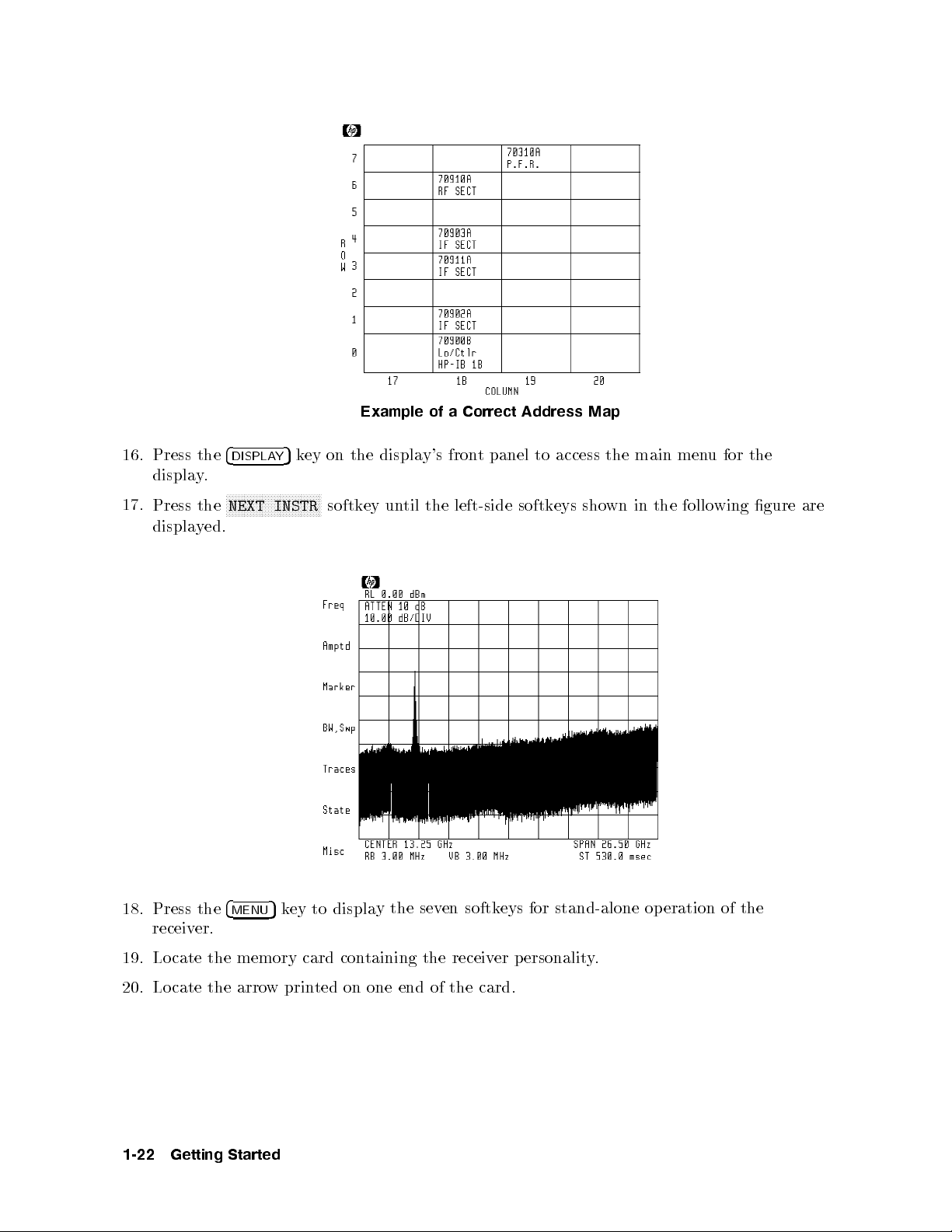
Example of a Correct Address Map
16. Press the
.
y
displa
17.
Press
displa
the
yed.
4
DISPLAY
NN
N
N
N
N
N
N
N
N
N
N
NEXT
5
key on the display's front panel to access the main menu for the
N
N
N
N
N
N
N
N
N
N
N
N
N
N
NN
NN
NN
INSTR
softk
ey un
til
the
left-side
softk
eys
sho
wn
in
the
follo
wing
gure
are
18. Press the
4
MENU
5
key to displa
receiver.
19. Locate the memory card con
Locate the arro
20.
1-22
Getting
wprin
Started
ted on one end of the card.
y the sev
en softkeys for
taining the receiv
stand-alone operation of the
er p ersonalit
y.
Page 43

21. Insert the card into the HP 70004A display's front-panel card slot. Match the card's
arrow with the arrow printed ab ove the card slot.
N
NN
NN
NN
NN
N
N
N
N
22.
23.
24.
Press
Press
Press
4
5
MENU
NN
N
N
N
N
N
N
N
N
N
N
N
N
N
N
N
1
MORE
N
N
N
N
N
N
N
N
N
N
N
N
N
N
N
NN
HP-MSIB
and
N
N
NN
N
N
N
N
N
N
N
N
N
N
N
of 3
N
NN
N
N
N
N
CARD
then
N
N
N
N
N
N
N
and then
N
N
N
N
N
N
N
N
N
N
the
to
left-side
displa
N
Misc
NN
N
N
N
N
N
N
N
N
N
N
N
N
N
N
N
catalog
les
all
y
.
ey
softk
N
N
N
N
N
N
N
N
N
N
N
N
N
N
N
N
N
N
N
N
N
N
NN
MSI
&
con
.
tained
on
the
memory
card.
25.
26.
27.
28.
card's
2053
If
write-protect
incorrectly
HP-IB
address
NN
NN
NN
N
N
Press
LOAD
N
N
N
N
N
N
N
N
Press
ENTER
Storage
The
.
address
using
N
N
N
N
N
N
N
N
N
N
N
N
N
NN
FILE
N
NN
NN
N
N
N
N
.
switc
HP-MSIB
and
the
NN
N
N
N
N
and
,
device
in
is
h
normally set
is
umeric
n
ter
en
error
SAFE
the
address
eypad.
k
for
1
is
the
displa
osition,
p
the
for
to 4.
le
n
ed,
y
If
um
or
card
the
er.
b
either
the
is
address
the
the
card
card's
same
is
missing,
is
HP-MSIB
address as
correct,
not
the
address
displa
the
ter
en
the
The front-panel LED next to the card slot lights indicating that the les are being
copied into the
4
USER
5
menu. This pro cess takes approximately 60 seconds.
NNNNNNNNNNNNNNNNNNNNNNN
.
e
b
y
visible.
Press
The
4
USER
left-side
and then
5
softk
eys,
RX_MODE
wn in
sho
to start
follo
the
the
wing
receiv
gure,
er
p
should
ersonalit
listed
is
y's
correct
Getting
Started
1-23
Page 44
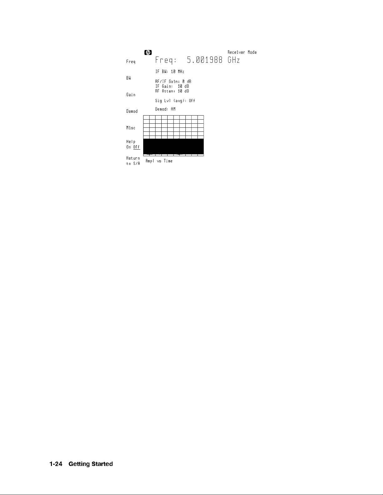
1-24
Getting
Started
Page 45
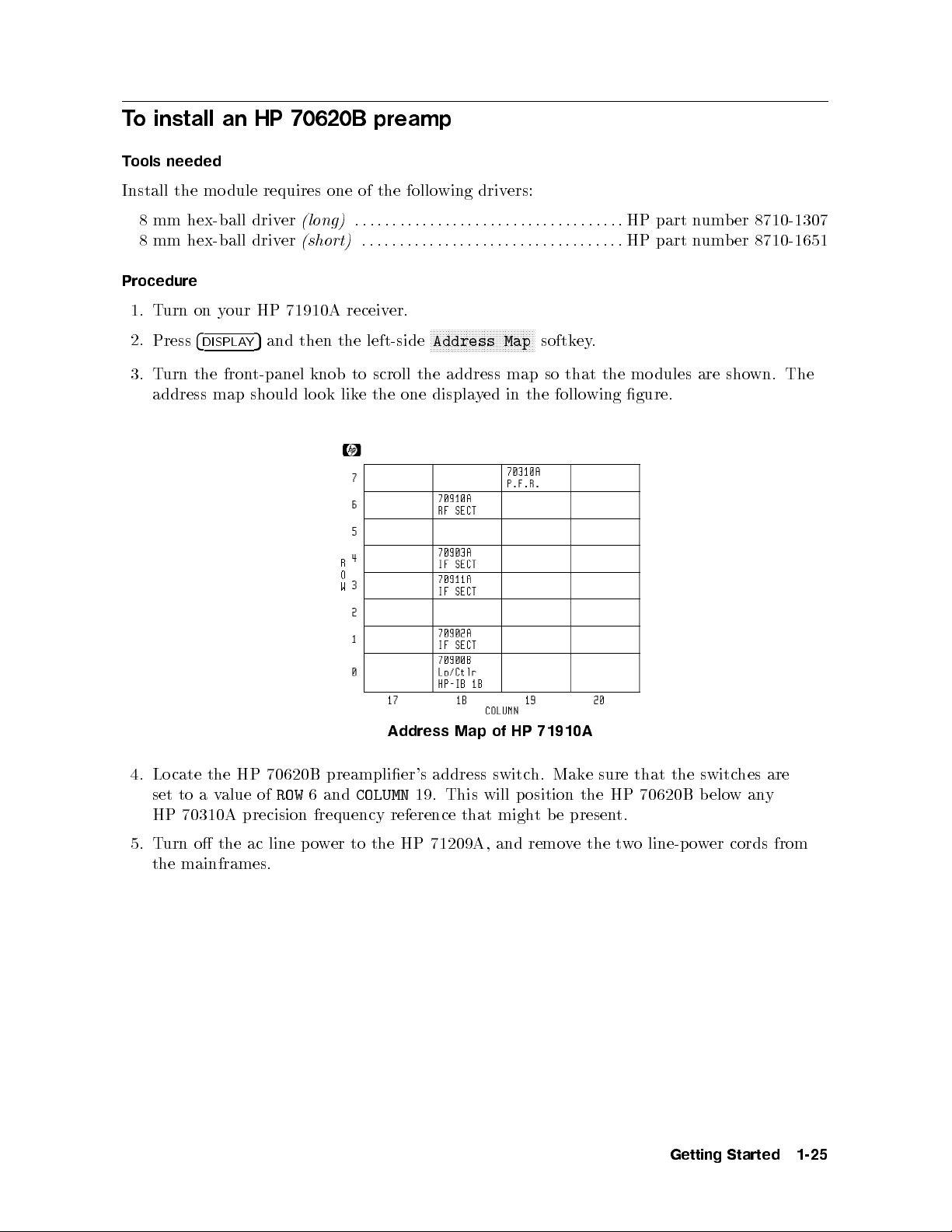
To install an HP 70620B preamp
Tools needed
Install the mo dule requires one of the following drivers:
8 mm hex-ball driver
8 mm hex-ball driver
(long)
(short)
::::::::::: ::::::::::::::: ::::::::::
:::::::::: ::::::::::::::: ::::::::::
HP part number 8710-1307
HP part number 8710-1651
Procedure
1. Turn on your HP 71910A receiver.
2.
Press
4
DISPLAY
5
and then the left-side
NNNNNNNNNNNNNNNNNNNNNNNNNNNNNNNNNNN
Address Map
softkey.
3. Turn the front-panel knob to scroll the address map so that the mo dules are shown. The
address map should look like the one displayed in the following gure.
Address
Map
71910A
HP
of
4. Locate the HP 70620B preamplier's address switch. Make sure that the switches are
set to a value of
ROW
6 and
COLUMN
19. This will position the HP 70620B b elowany
HP 70310A precision frequency reference that might be present.
from
cords
er
w
o
line-p
o
w
t
the
e
remov
5.
o
urn
T
mainframes.
the
the ac
line
71209A,
HP
the
to
er
w
o
p
and
Getting
Started
1-25
Page 46

6. Open the HP 70001A mainframe's front-panel door to expose the hex-lock screw.
7. Using an 8 mm hex-ball driver, turn the hex-lo ck b olt to remove the blank panel that is
located to the right of the HP 70910A RF section.
8. Install the HP 70620B in the empty slot.
9. Connect a cable b etween the HP 70620B's front-panel
HP 70910A's front-pane
10. Set the HP 70001A mainframe's45LINE
11. Set the HP 70004A mainframe's45LINE
12. If an
ERR
LED remains on, check the address map as described in the following steps.
a. Press
b.
4
DISPLAY
Press the left-side
5
.
RF OUTPUT
NNNNNNNNNNNNNNNNNNNNNNNNNNNNNNNNNNN
Address Map
connector.
switch to ON.
switch to ON.
softkey.
RF INPUT
connector and the
c. Turn the front-panel knob to scroll the address map so that it lo oks similar the one
shown in the following gure. Your receiver maynothave an HP 70310A precision
that the
such
is
dules
mo
the
of
order
the
that
sure
e
to
Mak
w
lo
is
are as
est)
not imp
shown
ortant.
in the
following
gure.
The
cation
lo
frequency
addresses
R
y
empt
reference.
(highest
addresses
W
O
RO
of
W
the
Press
13.
display.
14.
Press the
displayed.
1-26
the
Getting
4
DISPLA
NNNNNNNN
k
5
Y
NNNNNNNNNNNNNNNNNNNNNNNN
NEXT INSTR
Started
on
ey
softkey un
Example
display's
the
Correct
a
of
panel
t
fron
til the left-side
Address
to
Map
access
softkeys sho
the
for
u
men
main
the
wn in the following gure are
Page 47
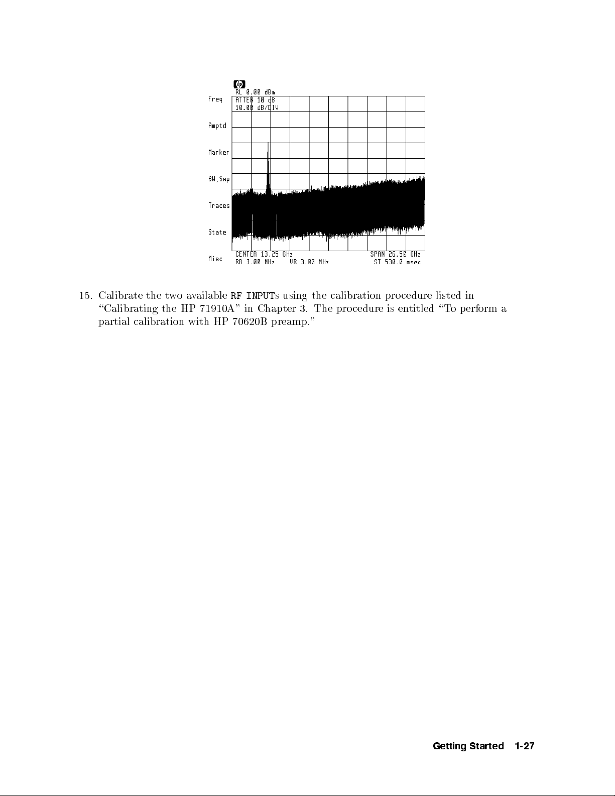
15. Calibrate the twoavailable
71910A"
HP
\Calibrating
partial calibration
the
with HP
RF INPUT
in
70620B preamp."
s using the calibration procedure listed in
Chapter 3.
The pro
cedure is
entitled
\T
o
erform
p
a
Getting
Started
1-27
Page 48

Maintaining the Receiver
The following procedures will help you to maintain the appearance and operation of the HP
71910A Wide-Bandwidth Surveillance Receiver.
To clean the HP 70004A's screen
Use a thin-lm cleaner and abrasion-free cleaning tissue or soft cloth to clean the display.
An example of a proper thin-lm cleaner is the Hewlett-Packard Display Cleaner (HP
part number 8500-2163).
CAUTION
Do not use hands or paper towels to clean the display's screen. These abrasive
materials may scratch the screen coating.
To change the mainframe's fuse
This procedure applies to either the HP 70001A mainframe or HP 70004A display/mainframe.
1.
T
urn
o
the
ac
line
to the
er
w
o
p
receiver,
and remo
ve
cables
er
w
o
line-p
the
from
er
w
o
p
the
outlet.
panel.
in
the
rear
follo
wing
2.
3.
Remov
fuse
The
a
Use
the
e
holder
small
w
o
line-p
lo
is
at-blade
cable
er
cated
screwdriv
is
from
the
the
line-p
to
er
connector
cable
er
w
o
out
prey
cated
lo
connector.
fuse
the
the
on
holder as
mainframe's
wn
sho
gure.
4. Chec
k the fuse
for damage. As sho
wn in the gure, a spare fuse is included in the assem
The metric 6.3A fuse (HP part number 2110-0703) can be used with b oth 120V and
230V power sources.
1-28
Getting
Started
bly.
Page 49
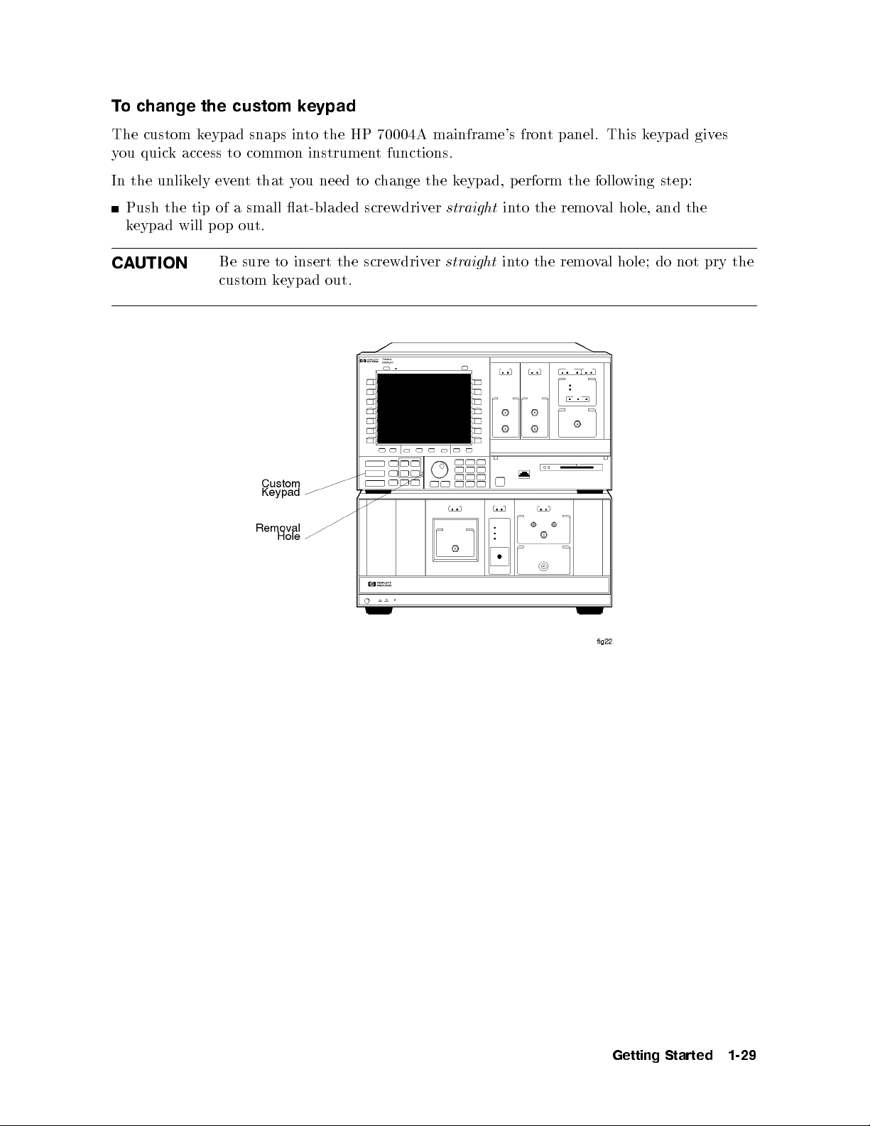
To change the custom keypad
The custom keypad snaps into the HP 70004A mainframe's front panel. This keypad gives
you quick access to common instrument functions.
In the unlikely eventthatyou need to change the keypad, perform the following step:
Push the tip of a small at-bladed screwdriver
keypad will pop out.
CAUTION
Be sure to insert the screwdriver
custom keypad out.
straight
straight
into the removal hole, and the
into the removal hole; do not pry the
Getting
Started
1-29
Page 50
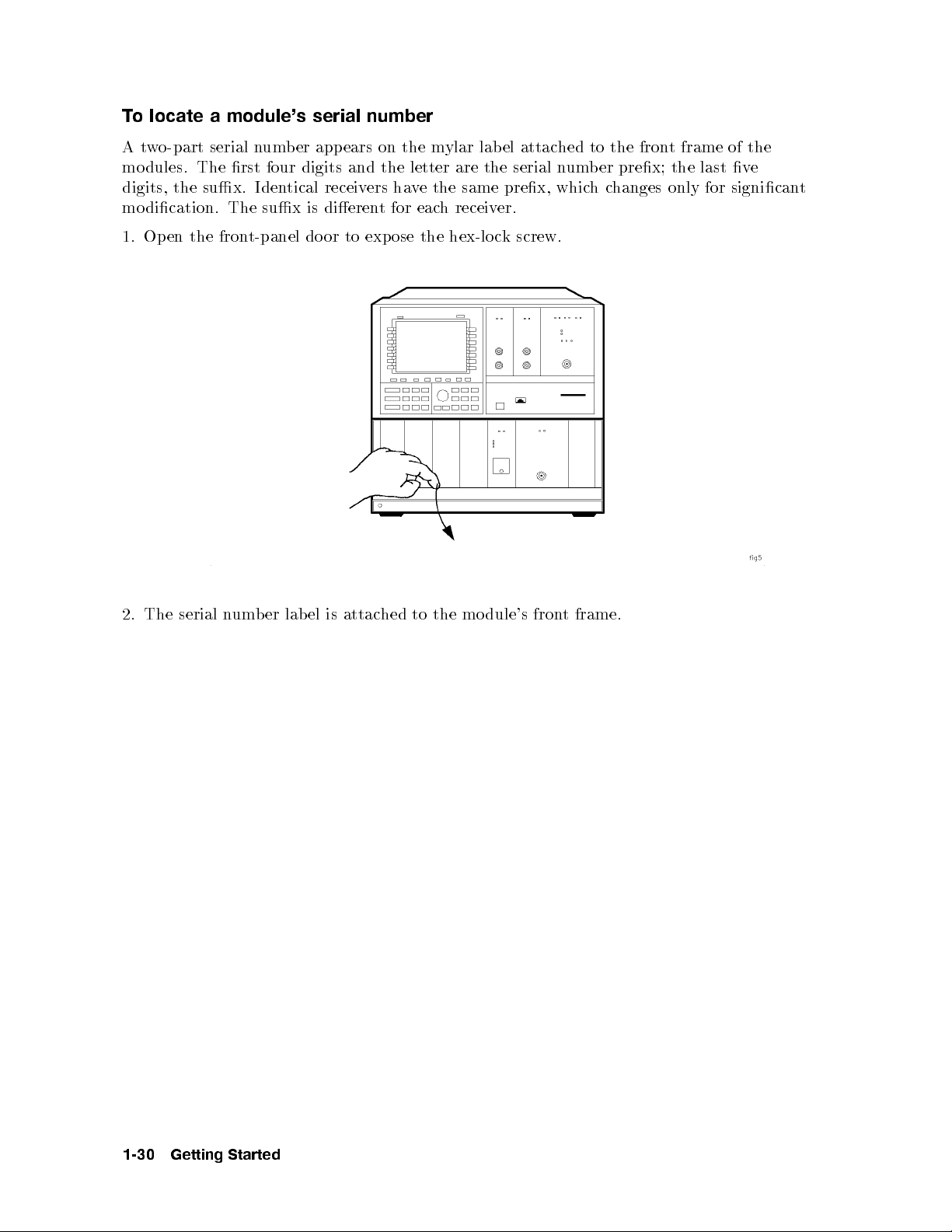
To locate a module's serial number
Atwo-part serial number appears on the mylar label attached to the front frame of the
modules. The rst four digits and the letter are the serial number prex; the last ve
digits, the sux. Identical receivers have the same prex, whichchanges only for signicant
modication. The sux is dierent for each receiver.
1. Open the front-panel door to expose the hex-lock screw.
2.
The
serial
n
um
frame.
t
dule's
mo
the
to
hed
attac
is
el
lab
er
b
fron
1-30
Getting
Started
Page 51
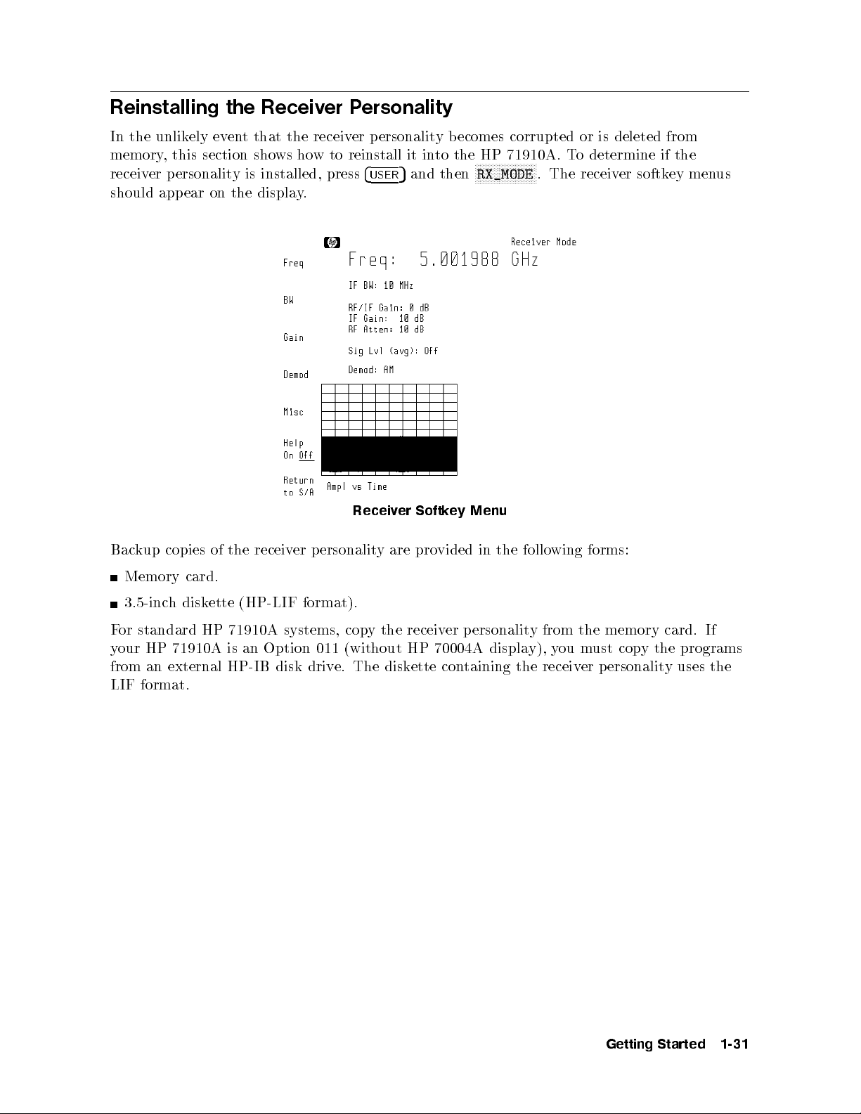
Reinstalling the Receiver Personality
In the unlikely event that the receiver personality becomes corrupted or is deleted from
memory, this section shows how to reinstall it into the HP 71910A. To determine if the
receiver personality is installed, press
4
USER
5
and then
NNNNNNNNNNNNNNNNNNNNNNN
RX_MODE
. The receiver softkey menus
should app ear on the display.
Menu
ey
Softk
Receiv
er
copies
kup
Bac
Memory
3.5-inc
or
F
our
y
from
h
standard
71910A
HP
external
an
LIF format.
card.
disk
of
ette
HP
receiv
the
(HP-LIF
71910A
an
is
HP-IB
er
systems,
Option
disk
ersonalit
p
format).
cop
(without
011
e. The
driv
yare
the
y
diskette
pro
receiv
70004A
HP
in
vided
ersonalit
p
er
displa
containing
follo
the
y
y),
the receiv
wing
from
you
forms:
the
must
p
er
memory
copy
ersonalit
If
card.
the programs
the
uses
y
Getting
Started
1-31
Page 52

To install from the memory card
1. Locate the memory card containing the receiver personality.
2. Locate the arrow printed on one end of the card.
3. Insert the card into the HP 70004A display's front-panel card slot. Match the card's arrow
with the arrow printed ab ove the card slot as shown in the following gure.
N
N
N
N
N
N
N
N
N
N
NN
N
Press
4.
5.
Press
6.
Press
If
write-protect
incorrectly
4
MENU
N
N
N
N
N
N
N
N
N
N
MORE
N
N
N
N
N
N
N
N
N
N
HP-MSIB
2053
and
5
N
N
N
N
N
N
N
N
N
N
N
N
N
N
N
NN
of
1
N
N
N
N
N
NN
NN
N
N
N
N
N
N
N
N
CARD
Storage
switc
The
.
then
N
N
N
N
N
N
N
N
and
3
N
N
N
N
N
N
N
N
N
N
N
to
device
h
HP-MSIB
the
then
displa
in
is
left-side
error
the
N
Misc
N
N
N
N
N
N
N
N
N
N
NN
N
N
N
N
N
N
N
N
N
N
catalog
all les
y
displa
is
SAFE
p
address for
softk
N
N
N
NN
N
N
N
N
N
N
N
N
N
N
N
N
N
MSI
&
contained
ed,
y
osition,
the card
.
ey
N
.
either
or the
memory
the
on
card
the
card's HP-MSIB
same
is the
card.
missing,
is
address
the
address is
the
as
HP-IB address and is normally set to 4. If the address is not correct, enter the correct
address using the numeric keypad.
Press
Press
The
into the
Press
NNNNNNNNNNNNNNNNNNNNNNNNNNNNN
LOAD FILE
N
NN
N
N
N
N
N
N
N
N
N
N
N
NN
N
ENTER
4
USER
.
t-panel LED
fron
4
USER
5
and then
5
, and enter 1 for the le number.
ligh
slot
card
the
to
next
menu. This process tak
NNNNNNNNNN
NNNNNNNNNNNNN
RX_MODE
to start the receiv
es appro
indicating
ts
ximately 60
er personality
the
that
seconds.
.
les are
7.
8.
9.
card's
displa
eing
b
listed
y's
copied
1-32
Getting
Started
Page 53
To install from a 3.5-inch diskette drive
This procedure reinstalls the p ersonalityinto a standard HP 71910A system. If you havean
Option 011 system, perform the next procedure in this section. The disk drivemust b e a 3.5
inch, CS80-compatible drive, such as an HP 9122.
1. Connect a 3.5-inch diskette drive to the HP 70004A display or HP 70001A mainframe.
Use an HP-IB cable.
2. Insert the diskette containing the receiver personality into the diskette drive.
3. Press
4.
5.
6.
4
5
.
MENU
Press the left-side
NNNNNNNNNNNNNNNNNNNNNNNNNNNNNNNNNNN
Press
MORE 1 of 3
NNNNNNNNNNNNNNNNNNNNNNN
Press
HP DISK
, and use the numeric keypad to enter the diskette drive's address.
NNNNNNNNNNNNNN
Misc
and then
softkey.
NNNNNNNNNNNNNNNNNNNNNNNNNNNNNNNNNNNNNNNNN
catalog & MSI
.
The default address is 0, unit 0, and volume 0. New addresses are entered in the form
A.UV
, where:
er.
b
b
um
olume
unit
a
disk
address.
The
er.
n
n
external
an
ette is
unit
olume
V
um
um
n
er
b
er
b
not in
b
um
um
n
should
0
of
ette
disk
the driv
er
b
and
Press the
7.
8.
Press
9.
Press
is
A
U
is
or
0
is
V
hard
for
example,
or
F
er
b
um
n
HP-IB
2053
If
e's
driv
NNNNNNNNNNNNNNNNNNNNNNNNNNNNN
LOAD FILE
NNNNNNNNNNNNNNNNN
ENTER
digit from
a
digit
a
refers
and
1
digit
a
disk
0.
of
address
NN
N
N
N
N
N
N
N
N
N
N
N
N
N
N
ENTER
Storage
is
de
co
1to
0
from
to
0
from
es. So,
driv
tering
en
accesses
This
3.
N
softkey
device
incorrectly en
, and enter a1for the le number.
to reinstall the le.
30, represen
represen
9,
to
individual
an
represen
9,
to
for
indicates
3.00
a
.
error
tered.
reading
ette
disk
is
ting the
the
ting
disk
the
ting
disk
address
an
in
displa
driv
the
ed,
y
ettes,
e's
driv
n
unit
slot.
e
volume
the
of
driv
left
either
HP-IB
um
n
v
3,
eof
a
typically
is
are
ers
e
b
a
driv
0.
olume
v
e
e, or
used
at
the
10.
The front-panel LED next to the card slot lights indicating that the les are being
seconds.
y
60
.
Getting
Started
copied
Press
4
USER
in
to
5
to
the
and
4
USER
then
men
5
N
N
N
N
N
N
RX_MODE
u.
NN
N
N
N
N
N
This pro
N
N
N
N
N
N
N
N
N
N
to
cess
start
the
tak
appro
es
receiv
er
p
ximately
ersonalit
1-33
Page 54
To install in an Option 011 instrument
This procedure reinstalls the p ersonality into an Option 011 instrument. It requires the use
of a computer and an HP-IB disk drive. The disk drivemust be a 3.5 inch, CS80-compatible
drive, such as an HP 9122.
In order to use this procedure, you must rst write a program that sends a string to the
HP 70900B instructing it to load the p ersonality. The string includes a \wait" command that
delays the loading of the p ersonality for 20 seconds. This pause gives you time to movethe
HP-IB cable from the computer to the disk drive. If you need more time, increase this wait
value in the command
WAIT 20
.
1. Write a program that sends the following string to the HP 70900B mo dule. (The HP-IB
address of the HP 70900B is equal to the HP-MSIB column address of the HP 70900B.)
MSI HPIB,0.1; WAIT 20; LOAD /RX/;
In the string, the digit 0 represents the disk drive's HP-IB address. The digit 1
represents the individual disk drive slot. This number is typically 0 or 1.
2. Use an HP-IB cable to connect the computer to the HP 70001A mainframe. Do not
computer.
connect
the
disk
driv
70001A
HP
the
to
e
mainframe
or
Insert
3.
Run
4.
complete
Disconnect
5.
driv
ait
W
6.
the
the
should
e
for
ette
disk
program
next
the
HP-IB
the
w
no
ersonalit
p
the
with
that
step.
cable
connected
e
b
y
y
the
ou
to
personalit
from
to
load in
in
the
the
to
wrote
to the
yin
1of
step
computer,
70001A
HP
HP
the
disk driv
this pro
and
mainframe.
70900B
e.
cedure.
connect
.
seconds
20
e
v
ha
ou
Y
driv
disk
the
to
it
to
disk
The
e.
1-34
Getting
Started
Page 55

Returning the Receiver for Service
Repackaging a receiver requires original shipping containers and materials or their equivalents.
Hewlett-Packard oces can provide packaging materials identical to the original materials.
Refer to Table 10-1 for the Hewlett-Packard sales and service oce nearest you.
CAUTION
Packaging materials not specied can result in instrument damage. Never
use styrene pellets to package electronic instruments. The p ellets do not
adequately cushion the instrument, do not prevent all instrumentmovement,
and can generate static electricity.
To return a receiver for service
1. Fill out a blue repair card (lo cated at the end of this chapter) and attach it to the
instrument. Send a copyofany noted error messages or other helpful performance data. If
a blue repair card is not available, include at least the following information:
a. Type of service required
Description of
b.
Name
c.
Return
d.
Mo
e.
f. F
List
g.
help
o
T
2.
materials.
instructions
a. W
F
b.
cardb
enough and
inc
and
del
serial
ull
of
prev
the
rap
instrumen
or
oard
on
hes
telephone
address
ber
um
n
um
n
accessories
y
an
damage
t
en
Original
result
instrumen
ts
carton
strong enough
sides
all
the problem
um
n
of returned
returned
of
er
b
returned
during
shipping
acceptable
in
an
in
t
eigh
w
that
kg
159
of
instrumen
the
of
whether
and
tec
of
er
b
instrumen
instrumen
with
transit,
materials
kaging.
pac
ti-static
than
less
lb) test
(350
to accommo
it
hnical
t
t
instrumen
k
pac
equiv
or
plastic
kg
54
strength. The
date the
pac
for
t
is
con
the
alen
to
(120
king
constan
tact
reduce
t
erson
p
t
instrumen
b
are
ts
the
use
lb),
instrumen
material.
termitten
in
or
the
in
t
wev
ho
est;
ossibilit
p
double-walled,
a
carton m
Allo
t.
t
factory
the
er,
of
y
e
ust b
at
w
pac
follo
ESD
corrugated
oth
b
least
kaging
wing
damage.
large
three
c. Surround the equipment with three to four inches of packing material to protect the
module and to preventmovement in the carton. If packing foam is not available,
the b est alternative is S.D.-240 Air CapTMfrom Sealed Air Corporation, Hayward,
California 94545. Air Cap is plastic sheeting lled with 1-1/4 inch air bubbles. Use
material
this
in
times
eral
sev
pink
pro
an
vide
ti-static
sucien
Cap.
Air
protection
t
rapping the
W
also
and
instrumen
en
prev
t
carton.
the
ement
v
mo
t
in
four
to
should
3. Seal the carton with strong
4. Mark the carton FRA
nylon adhesiv
GILE, HANDLE WITH CARE.
5. Retain copies of all shipping papers.
e tap e.
Getting
Started
1-35
Page 56

1-36
Getting
Started
Page 57

2
System Verification of Operation
Use automated tests to verify operation
The op eration verication tests for the HP 71910A are automated tests that are designed to
give a high condence level in the operation of the receiver in a reasonable time. For complete
information on requirements, loading, and running the verication test software, refer to the
HP 70000 Modular Spectrum Analyzer Instal lation and Verication Manual
.
Verify performance once every three years
It is recommended that a complete p erformance verication be p erformed once every three
y
b
or
ard
k
This
ears.
y
purchasing
e accomplished
b
can
the
HP
11990A System
either returning
by
Performanc
Hewlett-P
to
er
receiv
the
are.
w
soft
ests
T
e
ac
System
erification
V
Operation
of
2-1
Page 58

2-2
System
erification
V
Operation
of
Page 59

Operating
This chapter shows how to perform measurements using the HP 71910A. Measurements
generally involve the following two steps:
1. Use the instrument's sp ectrum analyzer features to search for a signal.
2. Switch the HP 71910A to receiver mo de to downconvert the signal for signal collection.
Entering receiver mo de replaces the standard spectrum analyzer softkey menus with new
receiver menus. Refer to Chapter 6 for diagrams of the receiver menus. Diagrams of the
spectrum analyzer menus are lo cated in the
Manual
Contents
.
:
:
:
:
:
:
:
Calibrating the
erform
p
o
T
erform
p
o
T
hing
Searc
cating
Lo
c
o
T
return
o
T
c
o
T
c
o
T
Using
Resolving Signals
Reducing Displayed Noise
Controlling the Sweep
Changing
Collecting Signals (receiv
Changing to
Selecting IF Outputs and Channel Filters
Mark
view
o
T
To resolve closely spaced signals
To reduce the displayed noise
Tochange the sweep time
set
o
T
change the cen
To
To switc
To select a new signal
To return to spectrum analyzer mode
select
o
T
adjust
To
c
o
T
increase
o
T
HP 71910A
calibration
a
calibration
a
Signals
for
Signals
hange
hange the
hange
hange
the
to
the
ers
signal
a
tinuous
con
ter-F
Cen
Receiver Mode
h to receiv
an
the
the
the
(sp
:
:
frequency
full
reference
amplitude
:
:
:
:
::
requency
output
IF
IF
IF-to-video
321.4
:
:
:
:
:
:
:
:
:
HP
with
ectrum
:
:
:
:
span
:
:
:
:
using mark
:
::
or
ter frequency step size
er mo de)
er mo de
and
analyzer mo
:
:
:
:
:
:
:
:
:
:
range
:
::
:
:
:
:
and
el
lev
units
:
:
::
::
:
:
:
ers
:
:
:
:
:
:
:
:
:
:
::::::::::::::: ::::::::::::::: ::::::::::::::: :::::::::::::
:::::::::::: ::::::::::::::: ::::::::::::::: ::::::::::::::: ::::
::::::::::: ::::::::::::::: ::::::::::::::: ::::::::::::::
single
sw
Step
:::::::::
:::::::::::::: :::::::
::::::
:::::::
:
:
:
:
::
:
bandwidth
video
bandwidth
bandwidth
MHz
HP 70000 Modular Spectrum Analyzer Operating
:
:
:
:
:
:
::
::
:
:
:
:
:
:
:
:
:
:
:
:
:
:
:
:
:
:
:
:
:
::
::
:
:
:
:
:
:
:
:
:
:
:
:
:
:
:
:
:
:
:
:
:
:
:
:
:
:
:
:
::
::
:
:
:
:
:
:
:
:
:
:
:
:
:
:
:
:
:
:
:
:
:
::
::
:
:
:
:
:
::
::
:
:
:
:
:
:
:
:
:
:
:
:
:
:
:
:
:
:
:
:
:
::
::
70620B
:
:
:
:
:
:
:
:
:
:
:
:
:
:
:
::
:
:
:
:
::::::::::::: ::::::::::::::: ::::::::::::::: ::::::::
eeps
Size
::::::::::: :::::::
:
:
:
preamp
de)
:
:
:
:
:
::
:
:
::
:
:
:
:
:
:
:
:
:
:
:
:
:
:
:
:
amplitude
:
:
:
:
:
:
:
:
:
:
:
:
:
:
:
:
:
:
:
:
:
:
::
::
::
::
:
:
:
:::::::::::: ::::::::::::::: ::::::::::::::: ::::::
:
:
:
:
:
:
:
:
::
:
:
:
:
:::::::::::::: :::
:::::::::::: :::::::::::::
:::::::::::: :::::::::::::
::::::::::::::: ::::::::::::::: :::::::::::::
:::::::::::::: ::::::::::::::: :::::::::::::
:
:
:
:
:
:
:
:
:
:
:
:
ratio
:
:
:
:
:
:
:
:
:
:
:
:
:
:
:
:
:
:
:
:
:
:
:
:
:
:
:
:
:
:
:
:
:
:
:
:
:
:
:
:
:
:
:
:
:
:
:
:
:
:
:
:
:
:
:
:
:
:
:
:
:
::
:
:
:
:
:
:
:
:
:
:
:
:
:
:
:
:
:
:
:
:
scale
:
:
:
:
:
:
:
:
:
:
:
::
::
:
:
:
:
:
:
:
:
:
:
:
::
::
:
:
:
:
:
:
:
::
::
::
::
:
:
:
:
:
:
:
:
:
:
:
:
:
:
:
:
:
:
:
:
:
:
:
:
:
:
:
:
::
:
:
:
:
::
:
:
:
:
:
:
:
:
:
:
::
:
:
:
:
:
:
:
::
:
:
:
:
:
:
:
:
:
:::::::::::: :::::::::::
::::::::::::: ::::::::::::
::::::::::: :::::::::::
:::::::::::: :::::::::::::
:
:
:
:
:
:
:
:
:
::
:
:
:
:
:
:
:
:
:
::
:
:
:
:
:
:
:
:
:
:
:
:
:
:
:
:
:
:
::
:
:
:
:
:
:
:
:
:
:
:
:
:
:
:
:
:
:
:
::
:
:
:
:
:
:
:
:
:
:
:
:
:
:
:
:
::
:
:
:
:
:
:
::
:
:
:
:
:
:
:
:
:
:
:
:
:
:
:
:
:
:
:
:
:
:
:
:
:
::
:
:
:
:
:
:
:
::
::
:
:
:
:
:
:
:
:
:
:
::
:
:
:
:
:
:
:
:
:
:
:
:
:
:
:
:
:
:
:
:
:
:
:
:
:
:
:
:
:
:
:
::
::
::
::
:
:
:
:
:
:
::
:
:
:
:
:
:
:
:
:
:
:
:
:
:
:
::
:
:
:
:
:::::::::::: ::::::
::::::::::
::::::::
:
:
:
:
:
:
:
:
:
:
:
:
:
:
:
:
:
:
:
:
:
:
:
:
:
:
:
:
:
:
:
:
:
:
:
:
:
:
:
:
:
:
:
:
:
:
:
:
:
:
:
:
:
:
::
:
:
:
:
:
:
:
:
:
:
:
::
:
:
:
:
:
:
:
:
:
:
:
:
:
::
:
:
:
:
::
:
:
:
:
:
:
:
:
:
:
:
:
:
:
:
:
:
:
:
::
:
::
:
:
:
:
:
:
:
:
:
:
:
:
:
:
:
:
:
::
3
:
:
:
:
:
:
:
:
:
:
:
:
:
:
:
:
::
3-11
:
3-11
3-12
3-12
3-13
3-13
3-13
3-14
:
3-14
3-15
3-17
3-17
3-19
3-19
3-20
3-23
:
3-23
:
3-23
:
:
:
:
3-3
3-3
3-3
3-5
3-6
3-7
3-8
3-8
3-8
3-9
3-9
Operating
3-1
Page 60
(preselector bypass)
To adjust the IF gain and RF attenuation
To select an Option 007 channel lter
Demodulating Signals
To demodulate the signal
To adjust IQ gain, oset, and quadrature
Viewing the Signal's Average Amplitude Level
To view the average amplitude
Measurement Examples
To search for and collect a pulsed RF signal
Tocharacterize a wide-bandwidth FM signal
Tocharacterize a wide-bandwidth digital transmission
Manually Collecting Signals
Using Manual Mode
To manually enter collection receiver mo de
To search for and collect a pulsed RF signal
Using a Preamplier
To use the HP 70620B preamp
o turn
T
Extending
trolling
Con
o
T
o
T
o
T
o
T
o
T
k
c
Blo
ou
Y
If
If
If
If
If
If the PREAMP On O softkey doesn't work
If there is a frequency shift in an HP 70911A output
o the
F
the
System
a receiv
ve
sa
delete
or
recall
o
w
t
view
e
v
Ha
ossible
the
title
Problem
a
is
and
compression
blank
write a
Diagrams
UNCOR
UNCAL and
UNCAL
P
::::::::::: ::::::::::::::: ::::::::::::::: ::::::::::::::: ::::::::::
preamp
requency
Conguration
state
er
a
instrumen
y
displa
the
on
:
:
:
:
:
:
y
displa
Usable
Usable
::::::::::: ::::::::::::::: ::::::::::::::: :::::::::::::: :::
::::::::::::: ::::::::::::::: :::::::::::::::
:::::::::::: ::::::::::::::: ::::::::::::::: ::::::::::::::: :::::
:::::::::::: ::::::::::::::: ::::::::::::::: :::::::::::::
:::::::::::: :::::::::::::: ::::::::::::::: :::::::::
:::::::::::::: ::::::::::::::: :::::::::::::: ::::::::::::::: ::
:::::::::::::: ::::::::::::::: ::::::::::::::: :::::::::::::::
::::::::::::: ::::::::::::::: ::::::::::::::: ::::::::::::::: :::::
::::::::::: ::::::::::::::: ::::::::::::::: ::::::::::::
:
:
:
:
de
mo
er
receiv
in
::
:
:
:
:
::
:
:
:
:
:
:
:
:
:
:
:
:
:
:
:
:
displa
displa
::
::
:
:
:
:
:
:
:
:
:
:
:
:
Mixers
:
:
::
:
:
:
:
:
:
:
:
:
:
:
:
:
:
:
:
:
:
:
:
::
Range
receiv
t
:
:
:
screen
:
:
:
:
:
:
:
ed
RBW
VBW
is
:
:
:
:
er
windo
:
:
::
:
:
:
:
:
:
::
:
:
:
::
::
displa
with
:
:
:
:
:
:
:
state
ws
:
:
:
:
:
:
:
:
:
::
:
:
:
:
:
:
:
:
:
limited
limited
ed
y
External
::
:
:
:
:
:
:
:
:
:
:
:
:
:
:
:
:
:
:
:
:
:
:
:
:
:
:
:
:
:
:
:
:
:
:
:
:
:
:
:
:
:
:
is
is
::
:::::::::::: ::::::::::::::: ::::::::::::
:::::::::: ::::::::::::::: ::::::::::::::
::::::::::: ::::::::::::::: :::::::::::
::::::::::: ::::::::::::::: :::::::::::
::::::::::: ::::::::::::::: ::::::::::
::::::::::::: ::::::::::::::
:::::::::::::: ::::::::::::::: :::::::::
:::::::::::::: ::::::::::::::: :::::::::::
::
::
::
:
:
:
:
:
:
:
:
:
:
:
:
:
:
:
:
:
::
::
::
::
:
:
:
:
:
:
:
:
:
:
:
:
:
:
:
:
:
:
:
:
:
:
:
:
::
::
::
::
:
:
:
:
:
:
:
:
:
:
:
:
:
:
:
:
:
:
:
:
:
:
:
:
::
::
:
:
:
:
:
:
:
:
:
:
:
:
:
:
:
:
:
:
:
:
:
:
:
:
:
:
:
:
:
::
::
:
:
:
:
:
:
:
:
:
:
:
:
:
:
:
:
:
:
:
:
:
::
:
:
:
:
:
:
:
:
::
::
:
:
:
:
:
:
:
:
:
:
:
:
:
:
:
:
:
:
:
:
:
::
::
:
:
:
:
:
:
:
:
:
:
:
:
:
:
:
:
:
:
:
::
:
:
:
:
:
:
:
:
:
:
:
:
:
:
:
:
:
:
:
:
:
:
:
:
:
:
:
::
:
:
:
:
:
:
:
:
:
:
:
:
:
:
:
:
:
:
:
:
:
:
:
::
:
:
:
:
:
:
:
:
:
:
:
:
::
:
:
:
:
:
:
:
:
:
:
:
:
:
:
:
:
:
:
:
:
:
:
:
::
:
:
:
:
:
:
:
:
:
:
:
:
:
:
:
:
:
:
:
:
:
:
:
:
:
::
:
:
:
:
:
:
:
:
:
:
:
:
:
:
:
:
:
:
:
:
:
:
:
:
:
:
:
:
:
:
:
:
:
::
:
:
:
:
:
:
::
:
:
:
:
:
:
:
:
:
:
:
:
:
:
:
:
:
:
:
:
:
::
::
:
:
:
:
:
:
:
:
:
:
:
:
:
::
::
:
:
:
:
:
:
:
:
:
:
:
:
:
:
ed
y
:
:
:
:
:
:
:
:
:
:
:
:
:
:
::
::
::
::
:
:
:
:
:
ed
y
:
:
:
:
:
:
:
::
::
::
::
:
:
:
:
:
:
:
:
:
:
:
:
:
:
:
:
::::::::::::: ::::::::::::::: ::::::::::
::::::::::::: :::::::::::::: ::::
::
::
:
:
:
:
:
:
:
:
:
:
:
:
:
:
:
:
:
:
:
:
:
:
:
:
::
::
:
:
:
:
:
:
:
:
3-24
3-24
3-24
3-26
3-28
3-28
3-30
3-30
3-31
3-31
3-36
3-41
3-44
3-46
3-47
3-49
3-52
3-53
:
3-53
:
3-54
3-55
:
3-56
:
3-58
:
3-59
:
3-59
:
3-60
:
3-62
:
3-65
:
3-66
:
3-67
:
:
3-68
3-69
:
3-70
3-71
3-2
Operating
Page 61

Calibrating the HP 71910A
The built-in calibration routine described in this section ensures maximum frequency
and amplitude accuracy as specied in Chapter 5 of this manual. The calibration routine
determines amplitude and frequency error factors for a number of parameters. For example, a
temperature compensation routine is included which decreases temperature induced errors on
the HP 70911A. Calibration only requires a few minutes to run.
To perform a calibration
1. Connect the HP 70900B mo dule's front-panel
front-panel
2. Press
3.
Press the left-side
4.
Press
The
perform
o
T
pro
This
the
on
is
Connect
1.
t-panel
fron
Press
2.
3.
Press
4.
Press
RF INPUT
4
5
.
MENU
NNNNNNNNNNNNNNNNNNNNNNN
CAL ALL
calibration
calibration
a
cedure
HP
calibrates
70910A
the HP
RF
4
5
MENU
left-side
the
N
N
N
N
N
N
N
NN
NN
N
N
N
N
select
.
N
N
N
N
N
NNNNNNNNNNNNNNNNN
Amptd
.
tak
RF
70900B
INPUT
NN
N
N
N
N
N
N
N
N
N
input
connector.
softkey.
three
es
with
the
section
mo
connector.
N
N
N
N
N
N
N
N
N
N
N
N
N
N
N
N
N
State
N
N
N
N
N
NN
and
four
or
HP
instrumen
one
and
dule's
.
ey
softk
NN
NN
N
N
N
N
then
IN
utes
min
70620B
for
t
input is
t-panel
fron
N
N
N
N
N
N
N
N
N
N
N
N
N
N
N
N
RF
2
oth
b
N
N
N
N
70910A
connector.
NN
NN
N
N
N
N
N
N
N
N
N
N
N
N
5. Press the left-side
Press
NNNNNNNNNNNNNNNNNNNNNNN
CAL ALL
6.
N
Amptd
softkey.
. The calibration takes three or four minutes to complete.
CALIBRATOR
complete.
to
preamp
INPUT
RF
the
on
CALIBRATOR
N
N
N
N
N
N
N
N
N
N
N
NN
NN
N
to
to the HP 70910A RF section's
input connector
preamp.
HP
70910A's
HP
One
70910A
RF
connectors.
70620B
HP
select
to
the
the
RF
INPUT
section's
7. When the calibration is nished, disconnect the cable from the HP 70910A RF section's
INPUT
t-panel
fron
INPUT
RF
connector.
8. Press the left-side
NNNNNNNNNNNNNNNNNNNNNNNNN
9.
NNNNNNNNNNNN
Press
select input
INPUT
connector.
10. Press the left-side
Press
NNNNNNNNNNNNNNNNNNNNNNN
CAL ALL
. The calibration takes three or four minutes to complete.
11.
connector, and
N
N
N
N
NN
N
N
N
N
N
N
N
N
N
N
N
State
softkey
N
and then
NNNN
NNNNNNNNNNNNN
Amptd
softkey
connect
.
NNNNNNNNNNNNNNNNNNNNNNN
NNNNNNNNNNNN
IN 1 70620B
.
70620B
HP
the
to
cable
the
to select HP 70620B preamplier's
preamplier's
RF
Operating
RF
3-3
Page 62

Searching for Signals (spectrum analyzer mode)
This section shows you two metho ds of searching for signals using the spectrum analyzer
functions. With the rst method, signals are located bychanging the displayed frequency
and amplitude range. The second method makes use of powerful marker functions. If your
wide-bandwidth surveillance receiver is an Option 011 single mainframe conguration, this
search capability will only be available through programming via the HP-IB bus.
Additional sp ectrum analyzer capabilities are described in the
HP 70900B Instruments
and includes explanations of the following features:
HP 70900B User's Guide for
Three separate color traces.
Smart marker features including next p eak, signal track, and marker pause.
Oversweep capability for faster sweeps.
Limit lines and audible beeps for detecting signals ab ove a threshold.
Three dimensional waterfall displays for time varying signals.
start-up
its
to
all
op
range
op
than
erate
ually
t
erating
MHz
3
as
is
will
Collecting
parameters
normal
a
used for
limit
Note
Note
an
at
If
press the
ving
ha
not
Do
signals.
analyzer.
MHz to
10
of
hes.
searc
hapter.
c
time
y
front-panel
turn
to
a
select
ou
y
If
example,
or
F
100
more
or
F
wan
you
4
w
o
p
the
resolution
the
do,
MHz,
information,
return
tto
ey.
5
k
IP
o.
er
bandwidth
instrumen
only
since
displa
instrumen
the
This resets
wider
not
will
t
linear
dynamic
ed
y
to
refer
detection
\Man
while
its
condition,
without
hing
searc
ectrum
sp
bandwidths
IF
for
use
Signals"
for
signal
in
this
3-4
Operating
Page 63

Locating Signals
Locating a signal is as easy as setting the frequency range and amplitude scale. When the
receiver is rst turned on, the frequency range is set to the full 100 Hz to 26.5 GHz span. Use
the
NNNNNNNNNNNNNN
Freq
menutochange the frequency range. Use the
NNNNNNNNNNNNNNNNN
Amptd
menuto change the reference
level and scale. By selecting the softkeys on these twomenus, you can view and search for
signals.
Note
In addition to using the softkey menus, don't forget the corresp onding
front-panel keys. For example, to set the frequency range and reference level
use
4
CENTER
5,4
SPAN
5,4
START
5,4
STOP
5
,and
4
REF LEVEL
5
.
Operating
3-5
Page 64
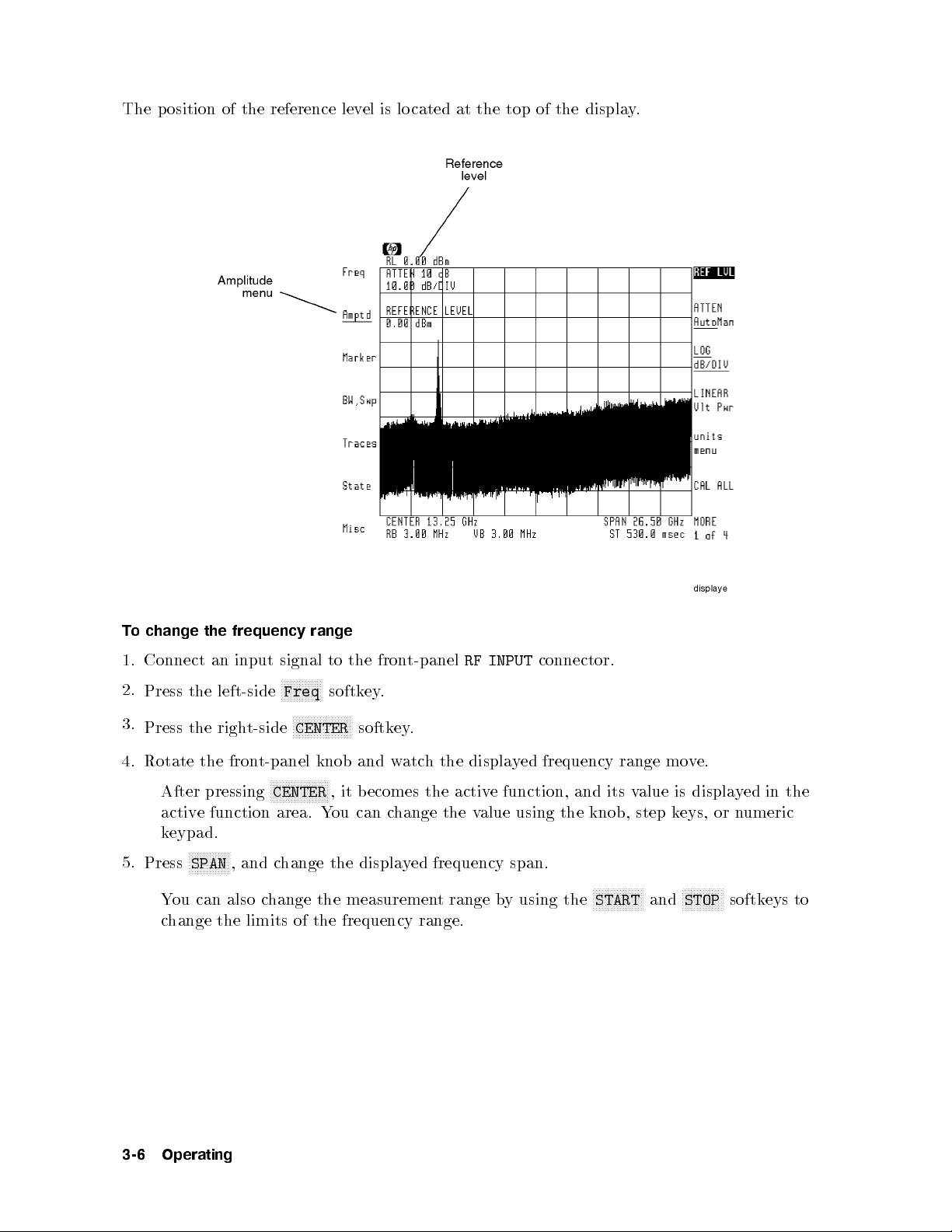
The position of the reference level is lo cated at the top of the display.
signal
N
N
N
N
N
N
N
N
N
N
Freq
NN
NN
N
N
CENTER
range
to
N
N
N
N
softk
N
N
N
N
N
N
NN
NN
the fron
ey.
N
N
N
N
softk
t-panel
.
ey
RF
INPUT
connector.
change
o
T
Connect
1.
2.
Press the
3.
Press
the
the
frequency
input
an
left-side
t-side
righ
4. Rotate the front-panel knob and watch the displayed frequency range move.
NNNNNNNNNNNNNNNNNNNN
After pressing
CENTER
, it becomes the active function, and its value is displayed in the
active function area. You can change the value using the knob, step keys, or numeric
keypad.
N
N
N
N
N
N
N
N
N
N
N
NN
5.
N
Press
SPAN
You can also
displa
,
and
hange
c
the
change the measuremen
ed
y
frequency
t range b
span.
y using the
N
N
N
NN
N
N
N
N
N
START
N
N
N
N
N
N
N
and
N
NN
N
N
N
N
N
STOP
change the limits of the frequency range.
N
N
N
N
N
N
softkeys to
3-6
Operating
Page 65

To return to full span
1.
Press the left-side
Press
NNNNNNNNNNNNNNNNNNNNNNNNNNNNN
FULL SPAN
2.
NNNNNNNNNNNNNN
Freq
.
softkey.
To change the reference level and amplitude scale
1.
Press the left-side
Press
NNNNNNNNNNNNNNNNNNNNNNN
REF LVL
2.
NNNNNNNNNNNNNNNNN
Amptd
softkey.
,andchange the reference level using the knob, step keys, or numeric
keypad.
3.
Press
NNNNNNNNNNNNNNNNNNNN
LINEAR
to select a linear scale, or press
NNNNNNNNNNNNNNNNNNNNNNNNNNNNNNNN
LOG dB/DIV
Then, enter the scale using the knob, step keys, or numeric keypad.
To change the amplitude units
menu
N
N
N
N
N
N
N
N
N
N
N
N
NN
UNITS
selection
N
N
N
N
N
N
N
N
selects
N
N
N
N
N
NN
N
N
N
N
selects
NNNNNNNNNNNNNNNNN
Amptd
.
NN
NN
NN
NN
N
N
N
N
N
AutoMan
is
annotation
softkey.
N
N
N
N
N
N
N
N
N
N
N
N
N
N
N
N
allo
receiv
the
annotation
the
ws
default
er's
in decib
w
in
receiv
els
atts.
to
er
setting.
relativ
select
to
e
the annotation
mW.
1
1.
Press the left-side
Press
Pressing
The
NNNNNNNNNNNNNNNNNNNNNNNNNNNNNNNN
units
NN
NN
N
N
N
N
N
N
Auto
2.
Pressing
Pressing
NN
NN
A
N
N
N
N
N
N
N
dBm
N
N
N
WATT
to select a logarithmic scale.
automatically.
Operating
3-7
Page 66
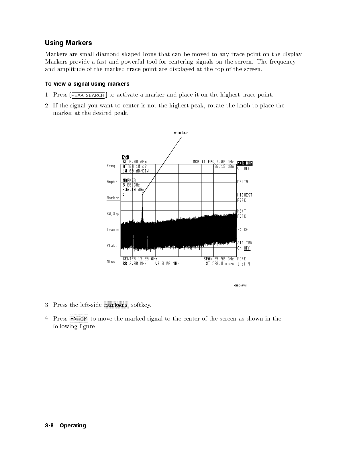
Using Markers
Markers are small diamond shaped icons that can b e moved to anytracepoint on the display.
Markers provide a fast and powerful to ol for centering signals on the screen. The frequency
and amplitude of the marked trace point are displayed at the top of the screen.
To view a signal using markers
1. Press
4
PEAK SEARCH
5
to activate a marker and place it on the highest trace point.
2. If the signal you wanttocenter is not the highest peak, rotate the knob to place the
marker at the desired peak.
3. Press the left-side
N
NN
N
N
N
N
N
N
N
N
N
N
NN
N
Press
wing
follo
Operating
N
->
CF
to
gure.
4.
3-8
NNNNNNNNNNNNNNNNNNNNNNN
markers
e
v
mo
the
softkey.
mark
ed
signal
to
the
cen
ter
of the
screen
as
sho
wn
in
the
Page 67
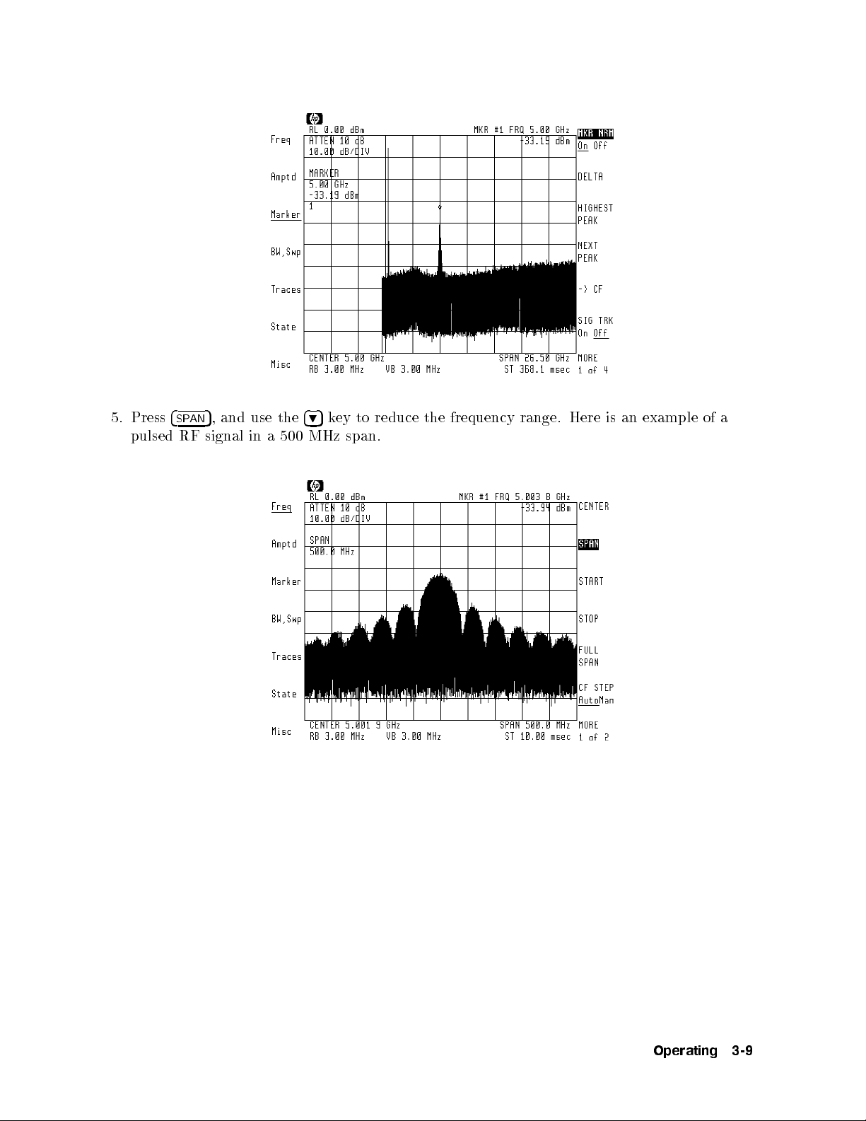
5. Press
pulsed RF
4
5
,andusethe
SPAN
signal in
a 500
495
key to reduce the frequency range. Here is an example of a
span.
MHz
Operating
3-9
Page 68

Resolving Signals
Often, two signals are closely spaced in frequency. The ability to display such signals as two
distinct responses is determined by the instrument's resolution bandwidth setting. Normally,
the sp ectrum analyzer automatically selects the optimum resolution bandwidth based on
the selected frequency span. As the following gures show, a resolution bandwidth that is
too wide causes adjacent signals to app ear as one. If a wide resolution bandwidth can hide
signals, why not always use the narrowest p ossible resolution bandwidth? The answer is that
as the resolution bandwidth is reduced, the sweep time increases and mayslowdown signal
searches. Manual resolution bandwidths are indicated by an asterisk (*RB) next to the screen
annotation.
N
N
N
N
N
N
N
N
N
N
N
N
N
Bandwidth
signals
N
NN
N
N
N
N
N
N
N
N
N
N
N
N
N
.
softk
ey
w
Narro
.
T
1.
2.
3.
o
resolve
Press
Press
Press
Resolution
Wide
closely spaced
N
NN
NN
NN
N
N
N
N
N
N
N
AutoMan
N
BW,Swp
N
N
NN
left-side
the
N
N
N
N
N
N
N
N
N
N
NN
NN
NN
BW
RES
495
to reduce the resolution bandwidth. Or, use the knob or numeric keypad to enter
a reduced resolution bandwidth.
4. To return to auto coupled resolution bandwidths, press the
that
NNNNNNNNNNNNNN
Auto
underlined.
is
Resolution
er
Bandwidth
NNNNNNNNNNNNNNNNNNNNNNNNNNNNNNNNNNNNNNNNNNNNNNNNNN
RES BW AutoMan
softkey so
3-10
Operating
Page 69

Reducing Displayed Noise
The displayed noise level (peak-to-peak noise variation) can be averaged bychanging the video
bandwidth or byaveraging successive traces. Changing the resolution bandwidth changes the
absolute level. Normally, the video bandwidth is coupled to the resolution bandwidth and is
automatically set. Manually entering a video bandwidth breaks this coupling. Manual video
bandwidths are indicated by an asterisk (*VB) next to the screen annotation.
KHz
3
displa
video
Press
Press
the
bandwidth:
left-side
the
NN
NN
N
N
N
N
N
N
N
N
N
N
BW
VID
o
T
reduce
Via
1.
2.
bandwidth.
3.
o
T
that
return
NNNNNNNNNNNNNN
Auto
to
is underlined.
Via video averaging:
1.
Press the left-side
clear-write
Press
2.
3.
Press the
ter the n
4. En
trace a
5.
Press
mo
N
N
N
N
N
N
N
N
N
N
N
NN
N
MORE
NNNNNNNNNNNNNNNN
VID AVG On Off
umber of sw
verages.
NNNNNNNNNNNNNNNNNNNNNNNNNNNNNNNNNNNNNNNNNNNN
VID AVG On Off
N
N
N
N
N
N
N
N
N
N
AutoMan
auto
de.
N
N
N
N
N
N
N
N
NN
1of
Filtering
Video
noise
ed
y
N
N
N
N
N
N
N
NN
N
N
BW,Swp
N
N
N
NN
NN
N
N
N
N
N
N
N
N
N
N
N
coupled
NNNNNNNNNNNNNNNNNNNN
Traces
N
N
N
N
N
N
N
NN
N
N
and
4
NNNNNNNNNNNNNNNNNNNNNNNNN
Filtering
Video
Hz
10
N
N
N
N
N
N
N
N
N
N
softk
N
and
video
.
ey
the
use
bandwidths,
knob,
umeric
n
press
eypad,
k
the
NN
N
N
N
VID
4
or
N
N
NN
NN
NN
N
N
BW
N
N
N
N
N
k
5
9
NN
N
N
N
N
N
N
N
N
AutoMan
ey
NN
reduce
to
N
N
N
N
N
N
N
N
N
N
N
N
NN
NN
softkey to enter the Traces menu. Trace A must be in the
N
N
N
N
N
N
N
NN
N
N
N
N
N
N
N
N
N
N
NN
N
N
N
N
N
N
N
N
N
N
N
NN
N
then
MORE
NNN
softkey so that
eeps to a
NNNNNNNNNNN
to
Off
2of
verage the displa
and then
.
4
NNNNNNNN
On
is underlined.
yed trace.
Or, use the default of 100
NNNNNNNN
On
to restart averaging at any time.
N
N
softk
the
ey
video
so
Operating
3-11
Page 70

Controlling the Sweep
The sweep speed is automatically set by the receiver. In fact, the receiver always uses the
fastest sweep possible while still maintaining a calibrated display.Manually setting the sweep
time disrupts the coupling used to maintain a calibrated display. Whenever a sweep time is
selected that degrades accuracy, the uncalibrated warning,
UNCAL
, appears on the display.
To change the sweep time
1.
Press the left-side
NNNNNNNNNNNNNNNNNNNN
BW,Swp
softkey.
2. Use the knob, step keys, or numeric keypad to enter the desired sweep time.
3.
To reestablish sweep time coupling, press
NNNNNNNNNNNNNNNNNNNNNNNNNNNNNNNNNNNNNNNNNNNNNNN
SWPTIME AutoMan
so that
NNNNNNNNNNNNNN
Auto
is underlined.
To set continuous or single sweeps
1.
Press the left-side
NNNNNNNNNNNNNNNNNNNN
BW,Swp
softkey.
2. Press one of the following softkeys:
N
N
N
N
N
N
N
N
N
N
N
N
N
N
N
N
N
N
N
N
N
N
N
N
N
N
N
N
N
N
N
N
CONT
N
N
N
N
NN
NN
NN
NN
N
SINGLE
o
T
SWEEP
N
N
N
N
N
N
N
N
N
rep
NN
NN
NN
NN
N
N
N
N
SWEEP
another
eat
to
N
tinuous
con
use
N
N
N
sw
to
eep
the
single
sweeping.
measuremen
sweep,
press
range
t
N
N
N
N
N
N
N
N
N
N
N
N
N
SINGLE
N
N
N
NN
NN
N
N
N
once.
N
N
N
N
N
N
N
N
N
N
SWEEP
N
N
N
N
N
again.
3-12
Operating
Page 71

Changing Center-Frequency Step Size
When center frequency is the active function, pressing the
485
and
495
keys steps the center
frequency to a new value. The default step size is one tenth of the displayed frequency span.
You can change the size of the steps to meet your search needs. The value you enter does not
depend upon the displayed span; you can jump to frequencies that are not currently displayed.
To change the center frequency step size
1.
Press the left-side
2.
Press the
3.
Press
NNNNNNNNNNNNNNNNNNNNNNNNNNNNNNNNNNN
MORE 1 of 2
NNNNNNNNNNNNNNNNNNNNNNNNNNNNNNNNNNNNNNNNNNNNNNNNNNNNN
FREQ STEP AutoMan
NNNNNNNNNNNNNN
Freq
softkey.
softkey.
and use the knob, step keys, or numeric keypad to enter a new
center frequency step size.
4. Press
5. Press
4
CENTER
485or495
5
to activate the center frequency function.
to step the center frequency.
Operating
3-13
Page 72

Collecting Signals (receiver mode)
This section shows you how to use the receiver mo de. Entering receiver mo de changes
instrument op eration in the following manner:
Displays receiver menus.
Sets xed-tuned op eration (zero span with the display showing amplitude versus time.)
Sets center frequency to the marker frequency or, if no marker is displayed, to the frequency
of the highest amplitude input signal.
Sets amplitude scale to linear.
Places reference level relative to the highest p eak.
The reference level is set to the next highest multiple of 10 dB from the peak's value. For
example, if the signal peak measures 26 dBm, the reference level is set to 30 dBm.
Downconverts the signal for analysis.
Selects a 10 MHz or wider IF bandwidth.
Selects a 10 MHz or wider video bandwidth.
Selects AM demo dulation.
Provides visual feedback that the signal is present (an amplitude versus time display). Only
or
linear
to
Press
detection
10 MHz.
4
5
USER
to
en
(not
ter
receiv
logarithmic)
de.
er mo
is
ailable
v
a
when
bandwidths
IF
are
greater
than
equal
3-14
Operating
Page 73
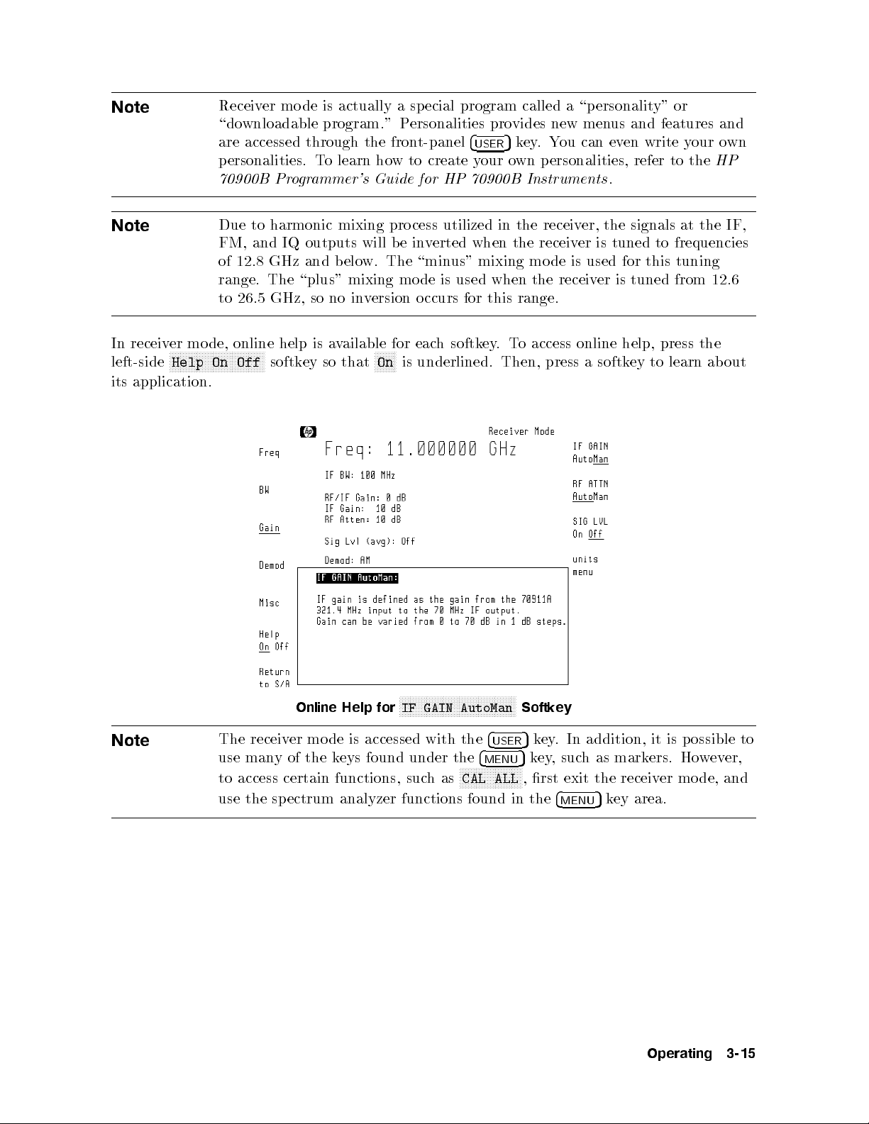
Note
Receiver mo de is actually a special program called a \personality" or
\downloadable program." Personalities provides new menus and features and
are accessed through the front-panel
personalities. To learn how to create your own personalities, refer to the
70900B Programmer's Guide for HP 70900B Instruments
4
USER
5
key.You can even write your own
.
HP
Note
Due to harmonic mixing process utilized in the receiver, the signals at the IF,
FM, and IQ outputs will be inverted when the receiver is tuned to frequencies
of 12.8 GHz and below. The \minus" mixing mo de is used for this tuning
range. The \plus" mixing mode is used when the receiver is tuned from 12.6
to 26.5 GHz, so no inversion occurs for this range.
In receiver mode, online help is available for each softkey.To access online help, press the
left-side
NNNNNNNNNNNNNNNNNNNNNNNNNNNNNNNNNNN
Help On Off
softkey so that
NNNNNNNN
On
is underlined. Then, press a softkey to learn about
its application.
Note
Online Help for
IF GAIN AutoMan
The receiver mo de is accessed with the
NNNNNNNNNNNNNNNNNNNNNNNNNNNNNNNNNNNNNNNNNNN
use manyofthekeys found under the
to
use
access
the
certain
ectrum
sp
functions,
analyzer
such
functions
NNNNNNNNNNNNNNNNNNNNNNN
as
CAL
found
4
USER
4
MENU
ALL
Softkey
5
key. In addition, it is p ossible to
5
key,suchasmarkers. However,
de,
mo
er
in
,
rst
the
exit the
4
MENU
5
receiv
ey
k
area.
Operating
and
3-15
Page 74

Changing to Receiver Mode
The procedures in this section showyou how to switchbetween receiver and spectrum
analyzer modes. In receiver mode, a small display shows the input signal's amplitude versus
time. Use this displayto quickly conrm that the signal is present and that the receiver
is properly tuned. For convenience, this xed-tuned display can be changed to the normal
spectrum analyzer display. This allows you to select another signal for down conversion
without leaving receiver mo de. Because a linear amplitude scale is used (and a linear
detector), the displayed dynamic range is limited.
To switch to receiver mode
NNNNNNNNNNNNNNNNNNNNNNN
1. Press
4
USER
5
and then
RX_MODE
.
If there are no markers shown on the screen, the instrument automatically tunes to the
highest displayed p eak.
If a marker is on, the instrument tunes to the signal at the marked frequency.
NNNNNNNNNNNNNNNNNNNNN
The
RX_MODE
Softkey
2. Once the receiver is x-tuned to the desired signal, the downconverted IF signal is available
at the HP 70911A module's rear panel for processing.
standard
The
vide
pro
outputs including Option 007 c
on IF
rear-panel
additional
70
MHz
IF
output
140
and
cen
is
MHz
tered
IF
at 321.4
signals
MHz.
respectiv
Option
.
ely
hannel lters, refer to the next section in this
001
information
more
or
F
002
and
chapter.
3-16
Operating
Page 75

3.
demo
o
T
a.
Press
t
Connect
b.
output
clearly
yp
e
N
N
N
N
N
N
AM
and
dulate
of
N
N
the
left-side
the
dulation
demo
N
N
N
N
N
N
N
and
PULSE
pro
005
appropriate
the
connector.
ed
mark
N
N
N
N
N
vide
N
N
if
wncon
do
N
N
N
N
NN
NN
N
Demod
N
N
N
demo
additional
AM
those
The receiver personality menus.
erform
and
p
then
press
signal,
erted
v
N
N
N
N
N
N
N
N
softk
ey
,
desired.
standard
dulation
external
pulse
and
options
I/Q
are
formats
and
test
are
are
formats
FM
equipmen
accessed via
presen
t.
the
t
the
to
the
wing steps:
follo
softk
on
ectiv
resp
the
VIDEO
ey that
the HP
ely
t-panel
fron
output.
corresponds
71910A. Option
.
dulation
demo
and
FM
to the
I/Q
004
are
Note
demo
The
regardless
necessary
is
VIDEO
connector.
dulated
whether
of
toggle b
to
outputs
they are
etw
The softk
alw
are
selected b
een AM
also
ey
\on"
ys
a
and pulse
toggles
y
at the
the
mo
w
et
b
front-panel
N
N
N
N
N
N
N
N
N
N
N
N
N
N
N
Demod
des
FM
een
N
N
softk
whic
connectors,
. The
ey
share
h
wideband
softkey
the
and
same
FM
narrowband which share the sameFMconnector. The softkey also oers
certain adjustments to the FM and IQ modes as described in this chapter.
Operating
3-17
Page 76

To select a new signal
Press
NNNNNNNNNNNNNN
SPAN
.
1.
2. Use the front-panel knob, step keys, or numeric keypad to change the displayed frequency
span.
3.
Press the left-side
Press
NNNNNNNNNNNNNNNNNNNN
CENTER
4.
NNNNNNNNNNNNNN
Freq
softkey.
, and use the front-panel knob, step keys, or numeric keypad to enter a new
receiver frequency.
5.
To return to xed-tuned op eration, press
NNNNNNNNNNNNNN
SPAN
and enter a span of 0 Hz.
To return to spectrum analyzer mode
NNNNNNNNNNNNNNNNNNNNNNNNNNNNNNNNNNNNNNNNN
Press the left-side
Return to S/A
softkey, and select one of the following to return to the
search receiver mo de:
NNNNNNNNNNNNNNNNNNNNNNNNNNNNNNNN
LAST STATE
to return the spectrum analyzer to the state it was in before the personality
was started.
N
NN
NN
N
N
N
N
N
N
N
N
N
N
N
N
N
N
N
N
N
N
N
NN
NN
N
FULL
Instrumen
GHz
N
N
N
N
NN
NN
N
N
N
N
N
N
N
NARROW
y
displa
bandwidth
IF
SPAN
N
N
N
N
N
N
N
SPAN
the
N
N
N
N
N
N
N
N
input
N
to
N
NN
return
t
N
to
not
is
Preset
return
signal.
c
ectrum
sp
the
condition.)
sp
the
(The
hanged.)
ectrum
span
analyzer
analyzer
to
set
is
a
to
its
to
alue
v
widest
frequency
a
ten
of
frequency span.
wide
span
IF
the
times
(100 Hz
enough
bandwidth.
| 26.5
to
The
3-18
Operating
Page 77

Selecting IF Outputs and Channel Filters
The IF outputs are available at the HP 70911A module's rear panel.
Standard IF Outputs
002
requiremen
atten
of
dB
of
ts
uation
the
is
a
external
ailable
v
of the
level
The
applying RF
IF signal
atten
uation
can b
IF
or
Option
adjusted
e
gain.
001
Up
and
to
Option
to
65
the
Outputs
IF
The amount of gain applied to the input signal is displayed on the screen as
represents the gain from the front-panel
MHz
output connector. Without an HP 70620B preamplier present, the
RF INPUT
connector to the Option 001 rear-panel
RF/IF Gain
by the following equation:
attenuation
F
R
0
ain
Fg
I
=
Gain
F
=I
F
R
information
more
or
F
on
is calculated,
gain
this
w
ho
refer
\RF/IF
to
Gain"
equipmen
steps.
5dB
in
RF/IF Gain
is dened
Chapter
in
y
b
t
. This
70
7.
Operating
3-19
Page 78

With 0 dB RF attenuation and 0 dB IF gain, the RF/IF gain from the HP 70910A's
ws:
follo
as
:
:
:
:
:
:
::
:
steps
is
:
:
:
:
:
::
:
:
:
:
:
:
:
::
using
applied;
+5
:
:
:
:
:
:
:
:
:
:
::
::
::
::
:
:
:
:
:
:
:
:
0
::
:
:
:
:
:
:
:
:
:
:
:
:
:
:
:
:
:
:
:
:
:
::
10
0
:
:
::
::
:
:
:
:
:
:
:
:
:
:
:
:
:
:
:
:
:
:
steps
dB
1
or
eys
k
step
the
there
no
is
automatic
gain
connector to
MHz
321.4
MHz
70
MHz
140
apply
can
ou
Y
knob or
the
trol.
con
the HP
IF
output
IF
IF
data
output
output
to
up
try
en
70911A's IF
:
:
:
:
:
:
:
::
::
:
:
:
:
:
:
:
:
:
:
:
:
::
::
of IF
dB
70
This
eys.
k
output
:
:
:
:
:
:
:
:
:
:
:
gain
gain
::
::
:
:
:
:
:
:
:
:
:
in
connectors
:
:
::
::
:
:
:
:
:
:
:
:
:
:
:
:
:
:
dB
10
ually
man
is
RF INPUT
dB
dB
dB
using
output
oscilloscop
an
at
has
e
Note
Note
When
the
Option 001
rear-panel
degraded
ou need
If y
321.4
bandwidth
IF
preserv
to
or
002
MHz
accuracy
the
e
installed,
is
OUT
OPT
phase
321.4
the
connector.
.
information
MHz
This
of
321.4
signal,
a
IF
is
MHz
use
ailable
v
a
or deep-memory IF digitizer to process the 70 MHz IF output of the receiver.
If you're downconverting signals b etween 2.7 and 26.5 GHz, you must turn o the microwave
preselector to obtain the widest possible IF bandwidth. For example, if you select a 100 MHz
bandwidth,
IF
greater than
to
but
36
the
MHz
micro
at
e preselector
v
a
w
HP
the
70911A's
on,
is
321.4
the
MHz
eectiv
output.
IF
bandwidth
e
This
will
is sho
wn
in
the
limited
e
b
following table:
3-20
Operating
Page 79

Approximate Widest Bandwidth of HP 70911A IF Outputs
Frequency 321.4 MHz
Output
100 Hz|2.9 GHz>48 MHz 40 MHz>48 MHz
2.7|26.5 GHz
preselector on
preselector o 100 MHz 40 MHz 70 MHz
1
Option 001
2
Option 002
3
The preselector's bandwidth increases at higher
frequencies and is nearly 60 MHz at a center frequency
of 20 GHz.
>
36 MHz3>
70 MHz
Output
36 MHz>36 MHz
140 MHz
1
Output
2
Operating
3-21
Page 80
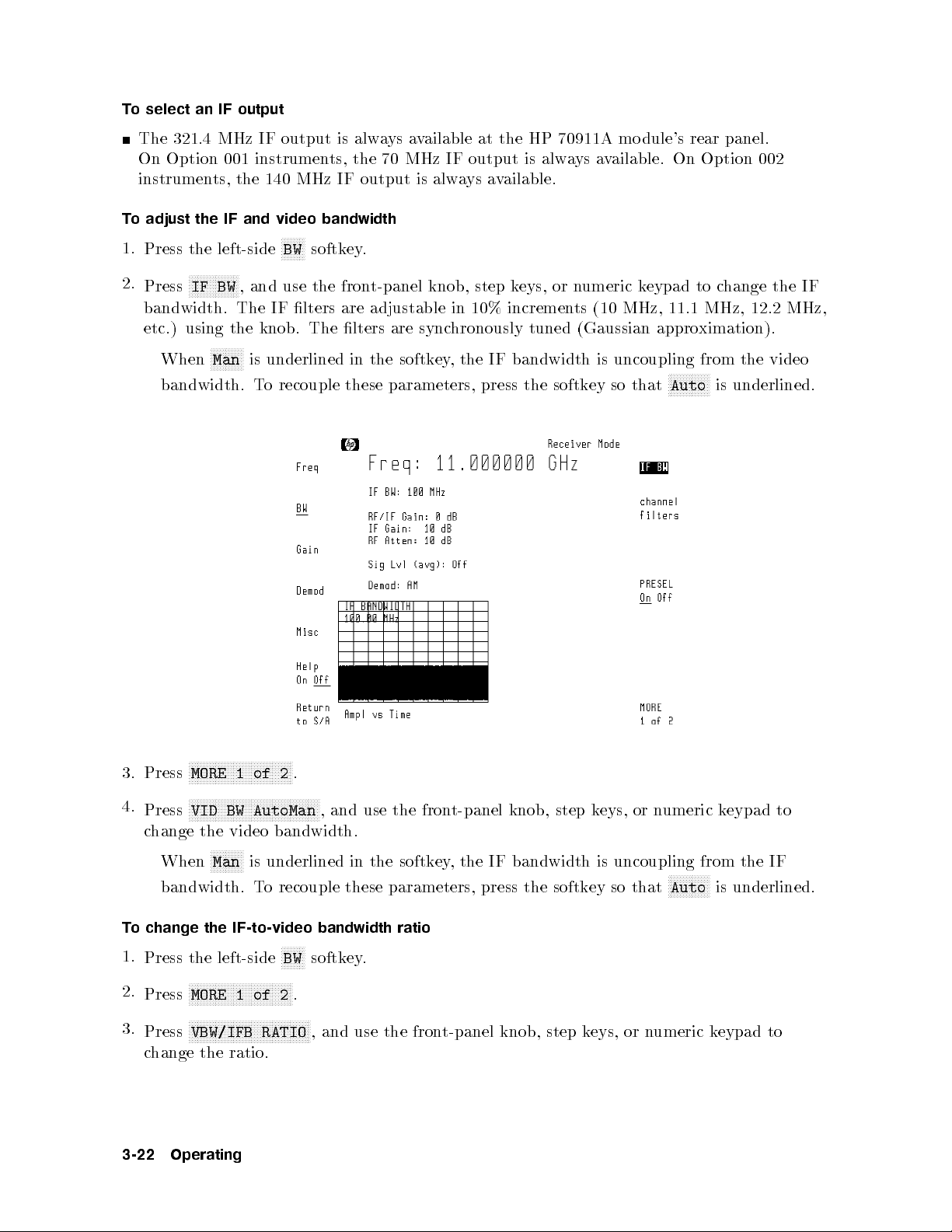
To select an IF output
The 321.4 MHz IF output is always available at the HP 70911A mo dule's rear panel.
On Option 001 instruments, the 70 MHz IF output is always available. On Option 002
instruments, the 140 MHz IF output is always available.
To adjust the IF and video bandwidth
NNNNNNNN
1.
Press the left-side
Press
NNNNNNNNNNNNNNNNN
IF BW
2.
BW
softkey.
, and use the front-panel knob, step keys, or numeric keypad to change the IF
bandwidth. The IF lters are adjustable in 10% increments (10 MHz, 11.1 MHz, 12.2 MHz,
etc.) using the knob. The lters are synchronously tuned (Gaussian approximation).
NNNNNNNNNNN
When
bandwidth. To recouple these parameters, press the softkey so that
Man
is underlined in the softkey, the IF bandwidth is uncoupling from the video
NNNNNNNNNNNNNN
Auto
is underlined.
3. Press
4.
Press
MORE 1 of 2
.
NNNNNNNNNNNNNNNNNNNNNNNNNNNNNNNNNNNNNNNNNNNN
VID BW AutoMan
, and use the front-panel knob, step keys, or numeric keypad to
change the video bandwidth.
NNNNNNNNNNNNNNNNNNNNNNNNNNNNNNNNNNN
N
N
N
N
N
N
NN
N
N
When
Man
bandwidth.
N
underlined
is
recouple
o
T
in the
these
softk
parameters,
To change the IF-to-video bandwidth ratio
NNNN
NNNNNNNNNNNN
NNNN
BW
softkey
.
.
, and use the front-panel knob, step keys, or numeric keypad to
1.
Press the left-side
2.
3.
3-22
NNNNNNNNNNNNNNNNNNNNNNN
Press
MORE 1 of 2
NNNNNNNNNNNNNNNNNNNNNNNNNNNNNNNNNNNNNNNNN
Press
c
VBW/IFB RATIO
hange
the ratio.
Operating
ey
,
the
bandwidth
IF
press
the
softk
uncoupling
is
that
ey so
N
N
N
N
N
N
N
N
Auto
from
N
N
N
NN
N
is
IF
the
underlined.
Page 81

To increase the 321.4 MHz bandwidth (preselector bypass)
1.
Press the left-side
2.
NNNNNNNNNNNNNNNNNNNNNNNNNNNNNNNNNNNNNNNNN
Press
PRESEL On Off
NNNNNNNN
BW
softkey.
so that
NNNNNNNNNNN
Off
is underlined.
To adjust the IF gain and RF attenuation
1.
Press the left-side
2.
To adjust the IF gain, press
NNNNNNNNNNNNNN
Gain
softkey.
NNNNNNNNNNNNNNNNNNNNNNNNNNNNNNNNNNNNNNNNNNNNNNN
IF GAIN AutoMan
, and use the front-panel knob, step keys, or
numeric keypad to change the displayed value.
3.
To adjust the RF attenuation, press
NNNNNNNNNNNNNNNNNNNNNNNNNNNNNNNNNNNNNNNNNNNNNNN
RF ATTN AutoMan
, and use the front-panel knob, step
keys, or numeric keypad to change the displayed value.
The amount of gain applied to the input signal from the RF input connector to the 70
MHz IF output is displayed on the screen as
RF/IF Gain
.
To select an Option 007 channel filter
With
MHz
gure
output
Note
Option
path.
IF
shows
on
to the
hed in
switc
e
b
can
5
lters
lter.
MHz
of 1.25,
It
Channel
5, 10,
as
w
20, and
created
Filter
y
b
MHz.
36
viewing
007
These
the shap
separate
a
installed,
lters
of
e
ectrum
sp
yshev
Cheb
vide bandwidths
pro
MHz
5
the
analyzer.
Option
hannel
c
hannel
c
007
This procedure requires that Option 007 be installed in the HP 71910A
Option 001
follo
The
MHz
70
the
.
70
wing
1. With Option 007 installed, press the left-side
NNNNNNNN
BW
softkey.
Operating
3-23
Page 82

The gure shown above is an example of a custom channel lter option which includes a
hannel
c
IF
lter
2.
3.
Press
Press
15 MHz
are
bandwidth lter
ailable
v
a
N
N
N
N
N
N
N
N
N
N
NN
NN
channel
a softk
N
N
N
N
N
N
N
N
N
N
N
N
N
NN
N
N
N
N
N
N
N
N
N
bandwidth.
N
1.25
N
N
N
N
N
N
N
N
N
NN
N
N
N
BYPASS
MHz
N
N
N
N
N
to
N
N
N
N
N
ey
N
N
,
prev
N
N
N
factory-installed
as
N
N
N
N
N
N
N
N
N
N
N
N
N
N
N
N
N
N
NN
NN
N
N
N
N
filters
select
to
N
N
N
N
N
N
NN
N
N
N
N
N
N
N
N
MHz
5
en
N
N
N
N
N
N
N
,
10
y
an
t
instead of
and
of
one
N
N
N
N
N
N
N
N
NN
N
N
MHz
hannel
c
then
the
N
N
N
N
,
a
options.
N
N
N
N
NN
NN
70
follo
N
N
N
NN
N
N
N
N
N
N
N
N
N
MHz
20
ltering.
20
N
N
N
N
N
N
MHz
wing
N
N
N
N
N
N
N
N
,
MHz
N
N
N
N
.
or
bandwidth
hoices:
c
N
N
NN
N
N
N
N
N
N
N
N
N
MHz
36
the
Custom
desired
lter.
N
N
N
N
N
N
N
select
to
lters
3-24
Operating
Page 83

Demodulating Signals
The video outputs are available on the HP 70911A mo dule's front panel. The default
demodulation is AM. When the receiver mode is started, any amplitude modulation
information present on the signal is demo dulated and made available at the HP 70911A
module's front-panel
VIDEO
connector.
y
If
Analog
FM
ha
ou
(Option
e
v
IQ
Option
an
(Option
005)
004
004)
or
Option
Standard
receiv
005
Video Output
follo
the
er,
wing
outputs
are
ailable:
v
a
Optional
Outputs
Operating
3-25
Page 84
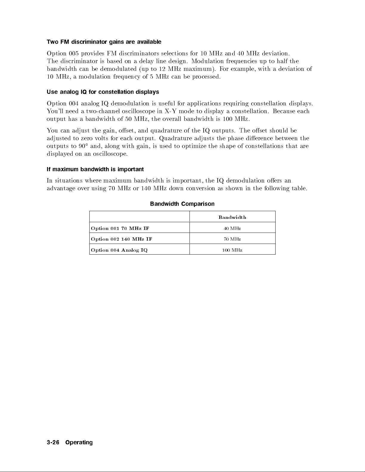
Two FM discriminator gains are available
Option 005 provides FM discriminators selections for 10 MHz and 40 MHz deviation.
The discriminator is based on a delay line design. Mo dulation frequencies up to half the
bandwidth can b e demodulated (up to 12 MHz maximum). For example, with a deviation of
10 MHz, a modulation frequency of 5 MHz can be processed.
Use analog IQ for constellation displays
Option 004 analog IQ demodulation is useful for applications requiring constellation displays.
You'll need a two-channel oscilloscop e in X-Y mo de to display a constellation. Because each
output has a bandwidth of 50 MHz, the overall bandwidth is 100 MHz.
You can adjust the gain, oset, and quadrature of the IQ outputs. The oset should be
adjusted to zero volts for each output. Quadrature adjusts the phase dierence b etween the
outputs to 90and, along with gain, is used to optimize the shape of constellations that are
displayed on an oscilloscop e.
If maximum bandwidth is important
an
In situations
o
tage
an
adv
where maxim
70
using
er
v
um bandwidth
140
or
MHz
MHz
dulation
demo
IQ
the
t,
ortan
imp
is
do
wn
con
ersion
v
as
shown
in the
oers
following
table.
Option
Option
Option
001
002
004
MHz
70
MHz
140
Analog
Bandwidth
IF
IF
IQ
Comparison
Bandwidth
MHz
40
MHz
70
MHz
100
3-26
Operating
Page 85

To demodulate the signal
1.
Press the left-side
NNNNNNNNNNNNNNNNN
Demod
softkey.
2. Select from one of the following demodulation formats:
NNNNNNNN
AM
selects AM demo dulation of the downconverted signal. The demodulated output is
available at the front-panel
VIDEO
connector. (video bandwidth = 0.3 x IF bandwidth.)
NNNNNNNNNNNNNNNNN
PULSE
at the front-panel
selects pulse demo dulation of the IF signal. The demodulated output is available
VIDEO
connector. (Video bandwidth is set to 100 MHz.)
NNNNNNNNNNNNNNNNN
FM WB
selects wide-bandwidth FM demodulation of the IF signal. This softkey is
only available on Option 005 instruments. The demodulated output is available at
the front-panelFMconnector. (FM peak-to-peak deviation of 40 MHz or less can b e
demodulated.)
NNNNNNNNNNNNNNNNN
FM NB
selects narrow-bandwidth FM demodulation of the IF signal. This softkey is
only available on Option 005 instruments. The demodulated output is available at
the front-panelFMconnector. (FM peak-to-peak deviation of 10 MHz or less can b e
dulated.)
demo
N
NN
NN
NN
N
selects
IQ
instrumen
004
analog
ts.
IQ
The
cessing
pro
output
is
of
ailable
v
a
the
IF
signal.
at the
softk
This
front-panel
ey
I
is only
and
av
connectors.
Q
ailable on
Option
adjusted
tly
enden
indep
e
b
fron
can
this
in
t-panel
section.
and
I
outputs
Q
so
adjust
o
T
Connect an
1.
oset
The
describ
IQ
and gain
in
ed
offset,
gain,
oscilloscop
\T
adjust
o
of the
quadrature
and
or
e
and
I
gain
IQ
oltmeter
v
Q
and
to
hannels
c
oset"
the
monitored.
N
N
N
N
N
NN
NN
N
N
N
N
N
N
N
N
N
softkey
N
N
N
N
or
N
Demod
.
N
N
N
N
N
N
N
N
N
NN
NN
N
Q GAIN
.
ey
softk
N
N
N
N
N
N
and rotate the front-panel knob to adjust the gain of each output
2.
3.
4.
Press
Press
Press
left-side
the
N
N
N
N
N
N
the
IQ
N
N
N
N
N
N
N
N
N
N
N
NN
NN
N
IGAIN
so that they are equal.
The displayed gain setting is a unitless digital-to-analog (DAC) value b etween 0 and
4095.
5.
Press
output
N
N
N
N
N
N
N
N
N
N
NN
N
OFFSET
I
zero
to
The displa
N
N
N
N
N
N
NN
N
or
N
N
N
N
N
NN
N
OFFSET
Q
N
N
volts.
yed oset setting is a unitless digital-to-analog (D
N
N
N
N
N
N
N
N
N
N
NN
N
N
N
N
,
and
rotate
the
fron
t-panel
knob
adjust
to
AC) v
the
alue b et
N
N
N
N
4095.
6. Press
NNNNNNNNNNNNNNN
QUADRATURE
and rotate the fron
t-panel knob to optimize the shape of the displa
NNNNNNNNNNNNNNNNN
constellation,.
as
they
that
oset
ween 0 and
can
of eac
yed
e
b
h
The displayed oset setting is a unitless digital-to-analog (DAC) value between 0 and
4095.
Operating
3-27
Page 86

Viewing the Signal's Average Amplitude Level
You can display the signal's average amplitude level in receiver mo de. The average is
computed at the end of every sweep and is shown in either linear or logarithmic units. You
can select the units that are used.
To view the average amplitude
1.
Press the left-side
Press
NNNNNNNNNNNNNNNNNNNNNNNNNNNNNNNN
units menu
2.
NNNNNNNNNNNNNN
Gain
.
softkey.
3. Press the softkey corresp onding to the desired units.
To return to the default units, press
4.
5.
NNNNNNNNNNNNNNNNNNNNNNNNNNNNN
Press
prev menu
NNNNNNNNNNNNNNNNNNNNNNNNNNNNNNNNNNNNNNNNNNNN
Press
SIG LVL On Off
.
to display the average amplitude value.
NNNNNNNNNNNNNNNNNNNNNNNNNNNNNNNNNNNNNNNNNNNNNNN
A UNITS AutoMan
so that
NNNNNNNNNNNNNN
Auto
is underlined.
Note
dulated
mo
Pulse
desensitization)
detector bandwidth
peak
signals
will ha
having
lo
ve
of
w
er
the
narrow
erage
v
a
digitizing
pulse widths
readings
el
lev
are
hardw
(and corresp
actual
than
displa
to
used
onding
to
due
the
y
large
the
signal.
3-28
Operating
Page 87
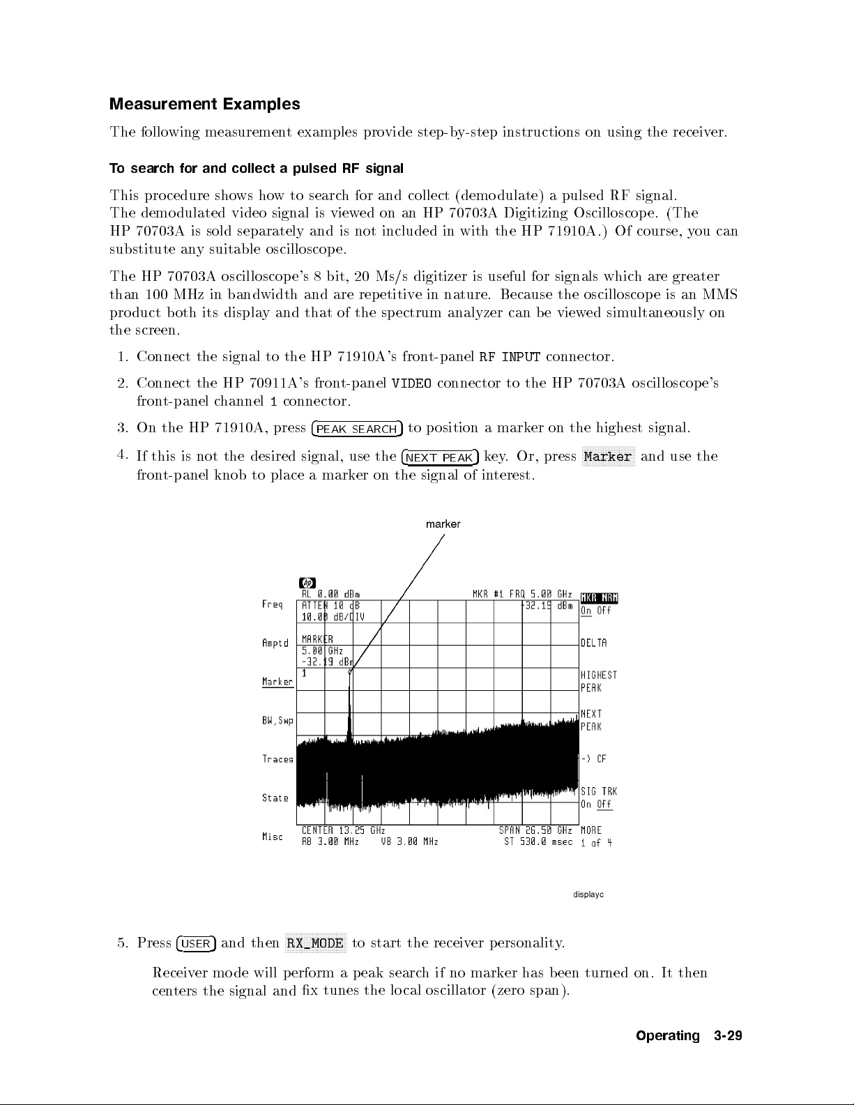
Measurement Examples
The following measurement examples provide step-by-step instructions on using the receiver.
To search for and collect a pulsed RF signal
This procedure shows how to search for and collect (demo dulate) a pulsed RF signal.
The demo dulated video signal is viewed on an HP 70703A Digitizing Oscilloscope. (The
HP 70703A is sold separately and is not included in with the HP 71910A.) Of course, you can
substitute any suitable oscilloscope.
The HP 70703A oscilloscop e's 8 bit, 20 Ms/s digitizer is useful for signals which are greater
than 100 MHz in bandwidth and are rep etitive in nature. Because the oscilloscope is an MMS
product both its display and that of the sp ectrum analyzer can b e viewed simultaneously on
the screen.
1. Connect the signal to the HP 71910A's front-panel
2. Connect the HP 70911A's front-panel
VIDEO
connector to the HP 70703A oscilloscope's
front-panel channel1connector.
4
to
press
signal, use
place a
PEAK
marker
SEARCH
the
on
5
4
the
to
NEXT
signal
osition
p
PEAK
3.
4.
the
On
If this
t-panel
fron
HP
is not
71910A,
the desired
knob
RF INPUT
mark
a
ey.
5
k
terest.
in
of
connector.
on
er
Or, press
the
N
N
N
N
Marker
highest
NN
NN
N
N
N
N
N
N
N
N
N
N
NN
signal.
and
use the
5.
Press
Receiv
cen
4
USER
ters
er
5
the
and
mo
then
will
de
signal
N
N
N
N
N
N
N
RX_MODE
erform
p
and
N
N
x
N
N
N
N
N
N
N
N
N
N
N
N
tunes
N
N
ersonalit
p
er
receiv
the
start
to
er
mark
no
if
h
searc
eak
p
a
the
lo
oscillator
cal
(zero
has
span).
b
.
y
een
turned
then
It
on.
Operating
3-29
Page 88

6. Press the left-side
the
Notice
that
NNNNNNNN
BW
NN
NN
N
IF
softkey.
N
N
N
N
N
NN
NN
BW
N
N
N
function
automatically
is
selected.
7.
8.
Press
the
If
the
signal's
underlined.
step
This
need
ou
y
If
9.
a.
Press
selected.
the
Use
b.
10.
Press the left-side
This sets the video bandwidth equal to 100 MHz bandwidth. With the default AM
demodulation, the video bandwidth is equal to approximately one third the value of the
IF bandwidth.
11.
12.
13.
Press
Press
DISPLA
the
NNNNNNNNNNN
build window
4
Press
Notice that when t
screen is remo
4
ey
k
5
"
cen
increases
adjust
to
left-side
the
4
and
5
#
.
5
Y
left-side
NNNNNNNNNNNNNNNNNNNNNNNNN
wice
t
ter
N
N
Demod
N
N
Config
ved.
4
N
N
set
to
frequency
bandwidth b
the
IF
the
N
N
N
N
N
N
NN
N
N
N
N
Gain
eys
k
5
"
NN
NN
NN
NN
N
N
N
N
N
N
softkey and then press
N
N
N
N
N
N
N
NN
N
N
N
N
N
N
N
N
NN
and then
wo windo
bandwidth
IF
the
ve
o
ab
is
erform
p
gain,
N
N
softk
to
N
N
N
N
NN
N
N
N
N
Display
ey
hange
c
N
NN
N
N
N
N
N
N
NNNNNNNNNNN
The
.
N
N
N
N
N
softk
NNNNNNNNNNNNNNNNNNNNNNNNN
STACK 2 WINDOWS
ws are displa
GHz,
2.7
turning
y
the
N
N
N
N
N
NN
N
N
N
N
GAIN
IF
gain
IF
the
.
ey
yed, the receiv
follo
N
N
N
N
N
N
NNNNNNNNNNN
100
to
press
the
o
wing
N
N
N
N
N
N
N
N
N
N
AutoMan
to a
N
N
N
N
N
N
N
PULSE
.
MHz.
N
PRESEL
micro
On
e
v
a
w
N
N
N
NN
NN
N
N
N
N
N
N
N
N
N
N
N
N
N
N
N
N
N
N
N
steps:
N
N
N
N
N
N
N
N
N
N
N
N
N
N
N
N
NN
N
N
function
suitable for
value
NN
NN
NN
NN
N
N
.
er's small frequency-v
N
N
N
N
N
N
N
N
N
N
N
N
N
N
Off
so
preselector
automatically
is
the signal
that
ersus-time
N
N
N
N
Off
N
N
N
N
N
N
lev
N
is
el.
3-30
Operating
Page 89
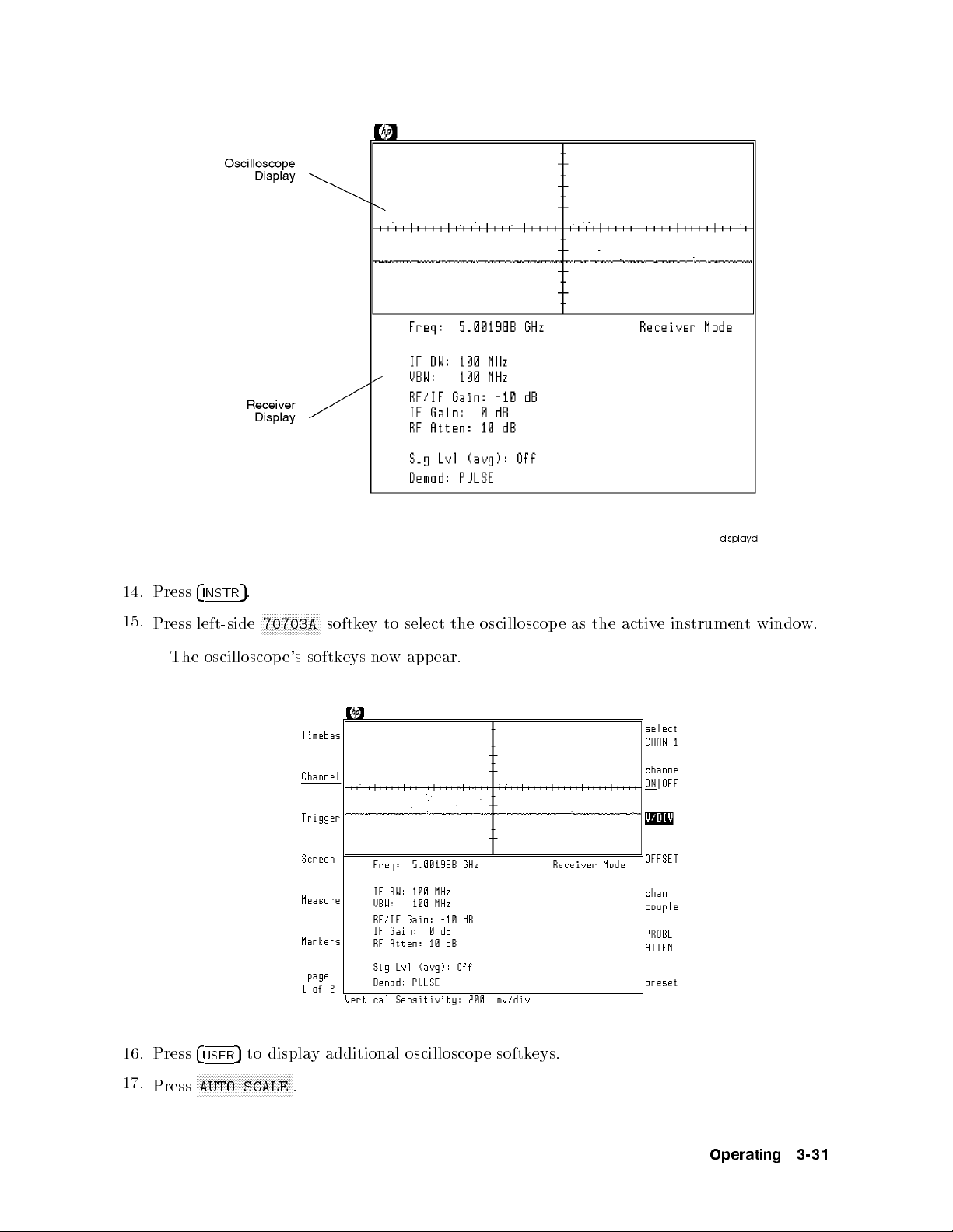
14.
15.
Press
Press
The
4
INSTR
.
5
left-side
oscilloscop
N
N
N
N
N
N
N
N
N
NN
N
N
N
70703A
e's
N
N
N
N
N
N
softk
softk
eys
ey
no
to
w
select
app
the
ear.
oscilloscop
instrumen
e
activ
the
as
e
t
w.
windo
16.
17.
Press
Press
4
USER
N
N
N
NN
N
N
N
AUTO
N
N
N
to
5
N
N
N
N
N
N
N
SCALE
N
N
N
N
N
displa
N
N
NN
N
N
N
N
N
.
y additional
oscilloscop
e
softk
eys.
Operating
3-31
Page 90

18. If the sweep time needs to be adjusted, perform the following steps:
a. Press the
b.
c.
19.
Press the
Press
Press the
4
USER
NNNNNNNNNNNNNNNNNNNNNNN
SEC/DIV
4
MENU
4
5
MENU
5
key.
,and change the sweep time as needed.
5
key.
NNNNNNNNNNNNNNNNNNNNNNN
key so that the left-side
Trigger
softkey is displayed.
20. Use the front-panel knob to adjust the trigger level for a stable display.
21.
22.
23.
Press
Press
Press
the
N
N
N
N
N
N
N
more
4
INSTR
left-side
N
N
NN
NN
N
N
N
N
N
N
N
1of
and
5
N
N
N
N
N
N
N
N
Measure
N
N
N
N
N
N
N
N
N
N
4
then
N
N
N
,
NN
and
N
N
N
N
N
N
N
N
N
N
N
N
N
N
N
N
N
N
70900B
N
N
N
N
softk
select
N
N
N
N
N
N
N
N
N
N
.
ey
er
ts.
men
us.
desired
the
N
NN
return
to
measuremen
the receiv
to
3-32
Operating
Page 91
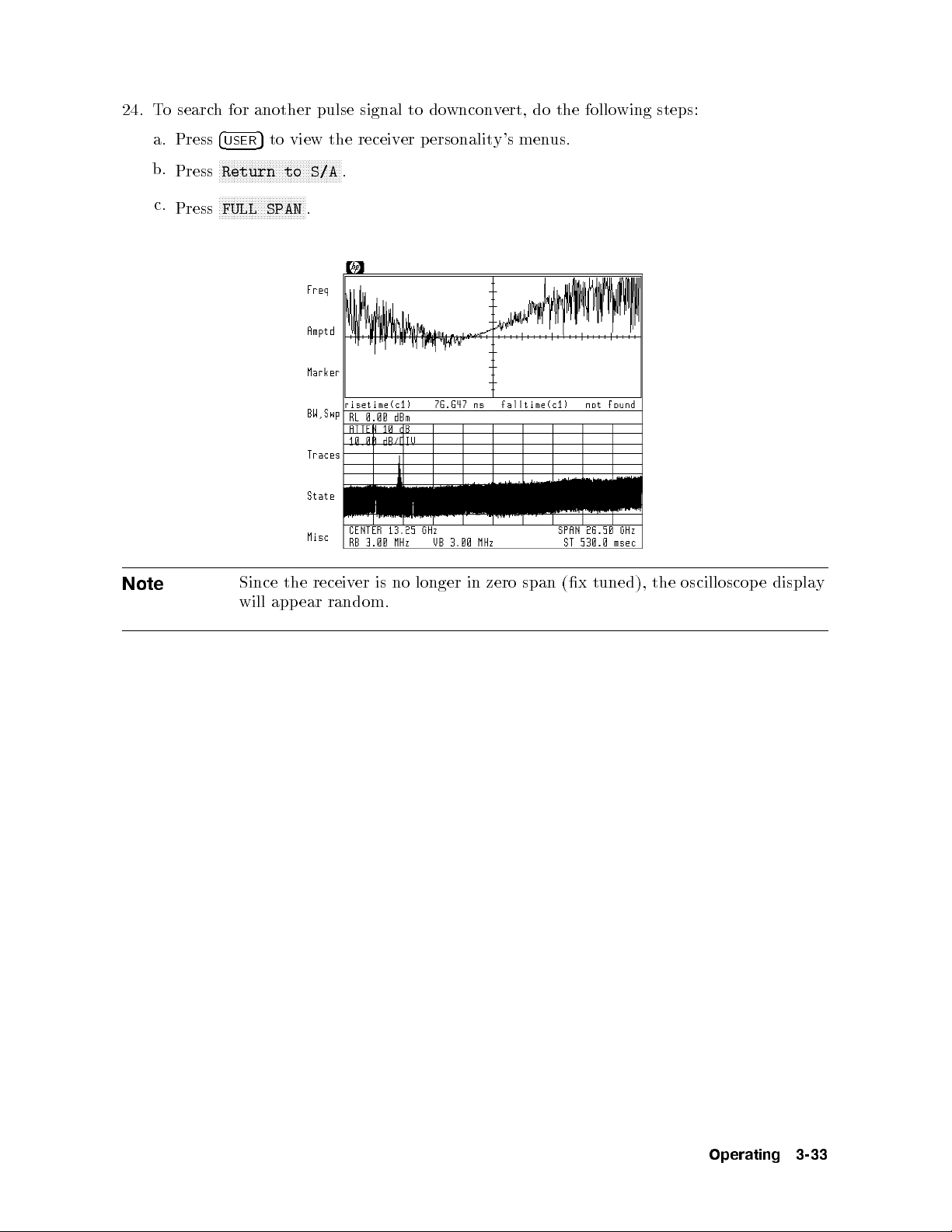
24. To search for another pulse signal to downconvert, do the follo wing steps:
Note
a. Press
b.
Press
c.
Press
4
5
to view the receiver p ersonality's menus.
USER
NNNNNNNNNNNNNNNNNNNNNNNNNNNNNNNNNNNNNNNNN
Return to S/A
NNNNNNNNNNNNNNNNNNNNNNNNNNNNN
FULL SPAN
Since
will
the
app
.
receiv
ear
random.
.
er is
no
longer
in
zero
span
(x
tuned),
oscilloscop
the
displa
e
y
Operating
3-33
Page 92
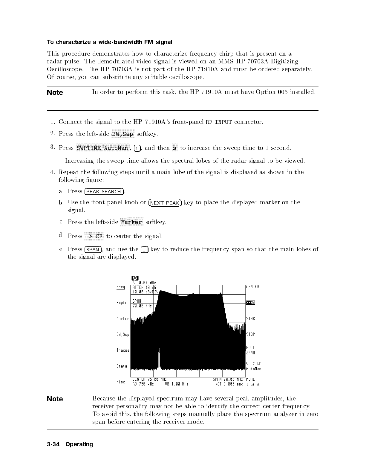
To characterize a wide-bandwidth FM signal
This procedure demonstrates howtocharacterize frequency chirp that is presentona
radar pulse. The demodulated video signal is viewed on an MMS HP 70703A Digitizing
Oscilloscope. The HP 70703A is not part of the HP 71910A and must be ordered separately.
Of course, you can substitute any suitable oscilloscope.
Note
1. Connect the signal to the HP 71910A's front-panel
2.
Press the left-side
3.
Press
In order to perform this task, the HP 71910A must have Option 005 installed.
RF INPUT
connector.
NNNNNNNNNNNNNNNNNNNN
BW,Swp
NNNNNNNNNNNNNNNNNNNNNNNNNNNNNNNNNNNNNNNNNNNNNNN
SWPTIME AutoMan,415
softkey.
, and then
NNNNN
s
to increase the sweep time to 1 second.
Increasing the sweep time allows the spectral lobes of the radar signal to be viewed.
4. Repeat the following steps until a main lob e of the signal is displayed as shown in the
4
the
gure:
PEAK
fron
SEARCH
t-panel
.
5
knob
or
4
NEXT
PEAK
marker
ed
y
displa
the
place
to
ey
k
5
on the
following
Press
a.
Use
b.
signal.
N
N
N
N
N
N
N
NN
N
N
N
N
N
N
N
N
N
N
N
to
and
displa
N
Marker
cen
use
ter
yed.
the
the
softk
signal.
4
5
#
.
ey
main lob
the
that
so
frequency
reduce
to
ey
k
the
span
c.
d.
e.
Press
Press
Press
the
the
N
NN
N
N
->
4
SP
signal
left-side
N
N
N
N
N
N
N
N
N
N
N
CF
,
5
AN
are
es
of
Note
3-34
Operating
Because
er
receiv
oid
v
a
o
T
b
span
the
ersonalit
p
this,
efore
displa
the
tering
en
ed
y
may
y
follo
wing
the
ectrum
sp
not
receiv
e
b
steps
er
ma
able
man
mo
y
ha
to
ually
de.
e
v
iden
several
tify
place
the
the
eak
p
correct
sp
amplitudes,
ter
cen
ectrum
analyzer
the
frequency
in
.
zero
Page 93

5. Press
press
4
CENTER
4
SPAN
5
and rotate the front panel knob to center the displayed response. Then,
5,405
, and then
NNNNNNNN
Hz
.
6. Connect HP 70911A's front-panelFMconnector to the HP 70703A oscilloscope module's
front-panel channel1connector.
7. Press
8.
9.
4
5
.
USER
NNNNNNNNNNNNNNNNNNNNNNN
Press
RX_MODE
.
Press the left-side
NNNNNNNN
BW
softkey.
NNNNNNNNNNNNNNNNN
Notice that the
10.
Press the
11.
If the signal's center frequency is above 2.7 GHz, press
4"5
IF BW
function is automatically selected.
key several times to set the IF bandwidth to 100 MHz.
underlined.
This step increases the bandwidth bybypassing the microwave preselector
12.
If
a.
ou
y
Press
need
the
adjust
to
left-side
the
N
N
N
N
N
N
N
Gain
N
N
N
IF
N
N
N
N
gain, p
softk
erform the
.The
ey
N
N
IF
N
N
N
N
N
N
N
N
selected.
IF
the
.
MHz)
(40
13.
14.
b. Use
Press
Press
This
the
the
N
N
N
N
N
N
N
N
N
FM
selects
4
5
and
#
left-side
N
N
N
N
N
NN
N
.
WB
the FM
4
eys to
5
k
"
N
N
N
N
N
N
N
N
N
N
N
N
N
NN
N
N
Demod
softk
wide-bandwidth
hange
c
ey
following
N
N
N
N
NN
NN
NN
NN
N
N
N
N
N
N
AutoMan
GAIN
gain.
discriminator.
NNNNNNNNNNNNNNNNNNNNNNNNNNNNNNNNNNNNNNNNN
PRESEL On Off
steps:
NN
NN
NN
N
N
N
N
N
N
N
N
N
N
N
N
N
function is
so that
Off
automatically
NNNNNNNNNNN
is
15.
16.
17.
Press
Press
Press
4
DISPLAY
left-side
the
N
N
N
N
N
N
N
N
N
N
N
NN
build
5
N
N
N
N
N
N
N
N
window
.
N
N
N
N
N
N
N
NN
N
N
N
N
N
N
N
N
N
N
N
N
N
N
N
Config
N
N
N
N
N
N
N
and
N
N
N
N
N
N
NN
N
N
Display
then
N
N
N
N
N
N
N
N
N
N
N
N
N
N
N
N
N
NN
STACK
N
NN
N
N
N
N
N
N
N
N
softk
N
N
N
N
N
N
N
N
N
N
N
N
2
ey.
N
N
N
N
N
N
N
N
N
N
NN
N
N
N
WINDOWS
N
N
N
N
N
N
N
N
N
N
.
Operating
3-35
Page 94

Notice that when two windows are displayed, the receiver's small frequency versus time
screen is not displayed.
18. Press
19.
4
5
INSTR
Press left-side
.
NNNNNNNNNNNNNNNNNNNN
70703A
softkey to select the oscilloscop e as the active instrument window.
The oscilloscop e's softkeys now appear.
20. Press
21.
22.
4
USER
NNNNNNNNNNNNNNNNNNNNNNNNNNNNNNNN
Press
AUTO SCALE
Press the
5
to display additional oscilloscope softkeys.
.
NNNNNNNNNNNNNNNNNNNNNNN
4
5
MENU
key so that the left-side
Trigger
softkey is displayed.
NNNNNNNNNNNNNNNNNNNNNNN
You may need to press
Trigger
several times.
23. Use the front-panel knob to adjust the trigger level for a stable display.
Note
24. If the sw
a. Press the
b.
Press
c.
Press the
25.
Press
the
measuremen
N
N
N
Press
26.
3-36
more
Operating
Due to the harmonic mixing process utilized in the receiver, frequency chirps
may appear backwards. That is, negative sloped chirps may displayshowing
positive slop e and visa versa. This phenomena occurs in frequency bands
where a minus mixing mo de is used (100 Hz | 12.8 GHz). Because the HP
MHz,
40
71910A's
ha
hirps
c
FM demo
wider
a
ving
dulator
bandwidth
has
maxim
a
will app
um
ear
eep time needs to be adjusted, perform the follo
4
5
key.
USER
NNNNNNNNNNNNNNNNN
NNNNNN
SEC/DIV
4
MENU
left-side
and then use the
5
key.
N
N
N
N
N
N
N
N
N
N
N
N
N
N
N
NN
N
N
N
N
N
N
Measure
softk
ey
,
4
#
and
5
and
use
4
5
keys to c
"
the
righ
t-side
bandwidth
distorted.
wing steps:
hange
men
of
the sweep time.
erform
p
to
us
v
ts.
N
N
N
N
N
N
N
N
N
N
N
N
N
N
N
NN
N
N
N
N
N
N
N
N
N
N
N
N
N
N
N
desired
and select
,
4
of
1
the
measuremen
ts.
frequency
arious
Page 95

Note
The HP 70703A oscilloscop e display shows amplitude versus time. To obtain
frequency versus time, you must perform an appropriate calibration.
27. Press
28. To search for another pulse signal to downconvert, do the follo wing steps:
4
a. Press
b.
Press
c.
Press
5
INSTR
and then
4
5
.
USER
NNNNNNNNNNNNNNNNNNNNNNNNNNNNNNNNNNNNNNNNN
Return to S/A
NNNNNNNNNNNNNNNNNNNNNNNNNNNNN
FULL SPAN
NNNNNNNNNNNNNNNNNNNN
70900B
.
to return to the receiver menus.
.
Operating
3-37
Page 96
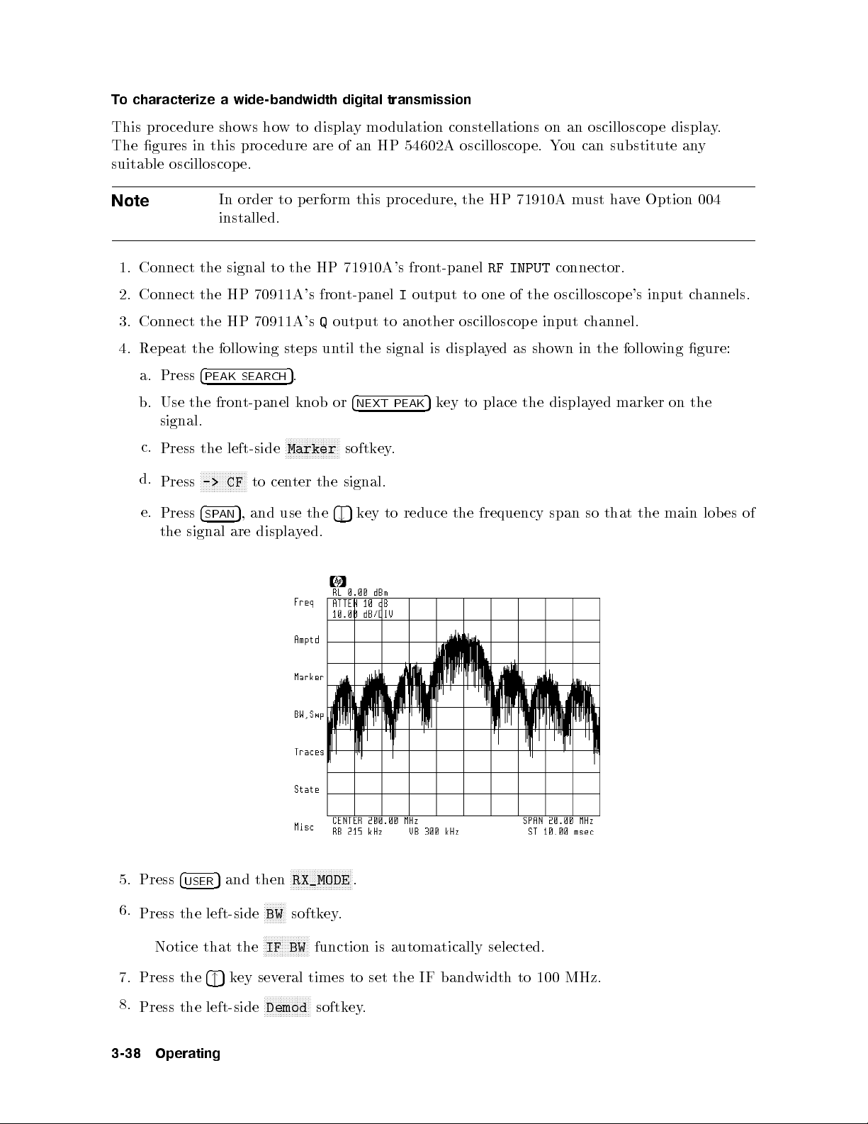
To characterize a wide-bandwidth digital transmission
This procedure shows how to display modulation constellations on an oscilloscop e display.
The gures in this procedure are of an HP 54602A oscilloscope. You can substitute any
suitable oscilloscope.
Note
In order to perform this pro cedure, the HP 71910A must have Option 004
installed.
1. Connect the signal to the HP 71910A's front-panel
RF INPUT
connector.
2. Connect the HP 70911A's front-panelIoutput to one of the oscilloscope's input channels.
3. Connect the HP 70911A'sQoutput to another oscilloscop e input channel.
4. Repeat the following steps until the signal is displayed as shown in the following gure:
a. Press
b. Use the front-panel knob or
4
PEAK SEARCH
5
.
4
NEXT PEAK
5
key to place the displayed marker on the
signal.
NN
NN
NN
N
N
N
N
N
N
N
N
N
N
N
N
N
N
to
and
displa
N
Marker
cen
use
ter
y
the
ed.
the
softkey
signal.
4
k
5
#
ey
.
to
reduce
frequency
the
span
so
that
the
main
lob
c.
d.
e.
Press
Press
Press
the
signal
the left-side
N
N
N
N
N
NN
NN
N
N
N
N
N
N
N
CF
->
4
,
5
AN
SP
are
es
of
5. Press
6.
4
USER
Press the left-side
Notice
7.
8.
3-38
Press
Press
Operating
the
the
5
and then
the
that
4
ey
k
5
"
left-side
NNNNNNN
N
BW
NNNNNNNNNNNNNNNNN
IF
eral
sev
N
N
N
N
N
N
N
N
Demod
NNNNNNNNNNNNNNNN
NNNNNNN
RX_MODE
softkey.
function
BW
times
N
N
N
N
N
N
N
N
N
softk
to
ey
.
is
set
.
automatically
bandwidth
IF
the
selected.
to
100
MHz.
Page 97
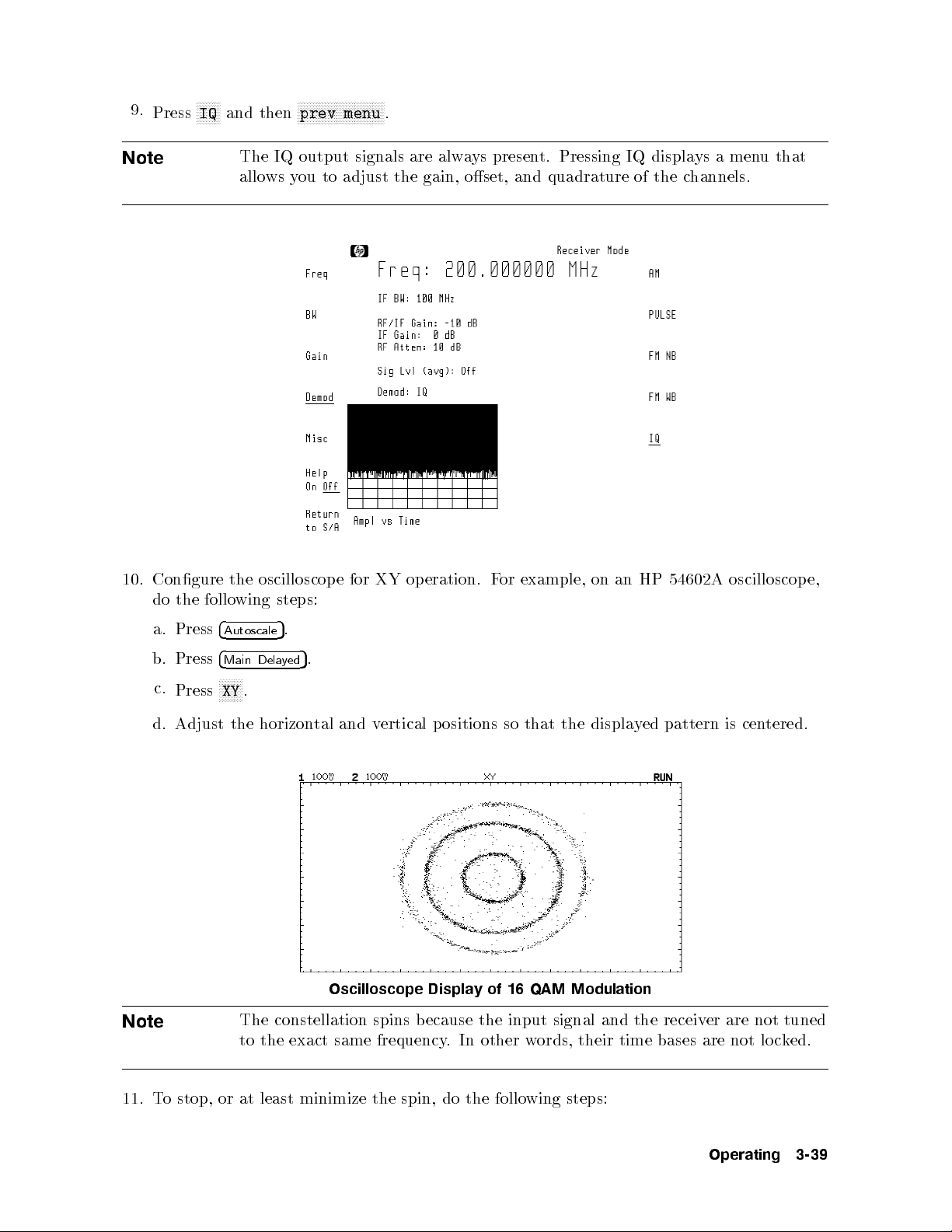
9.
Press
NNNNNNNN
IQ
and then
NNNNNNNNNNNNNNNNNNNNNNNNNNNNN
prev menu
.
Note
10.
Congure
follo
the
do
The IQ output signals are always present. Pressing IQ displays a menuthat
allows you to adjust the gain, oset, and quadrature of the channels.
oscilloscop
the
wing
steps:
example,
or
eration.
op
XY
for
e
F
on
54602A
HP
an
oscilloscop
e,
Note
a.
b.
c.
d.
Press
Press
Press
Adjust
4
Autoscale
4
Main
N
N
N
N
N
N
XY
the
Dela
N
N
.
.
5
5
ed
y
horizon
.
tered.
tal
and
ertical
v
ositions
p
that the
so
display
ed pattern
is cen
Oscilloscope Display of 16 QAM Modulation
The constellation spins because the input signal and the receiver are not tuned
c
lo
not
are
bases
time
to
the
exact
same
frequency
words,
other
In
.
their
k
ed.
11.
minimize
least
at
or
stop,
o
T
the
Operating
3-39
steps:
wing
follo
the
do
spin,
Page 98

a.
On the HP 71910A, press the left-side
b.
c.
NNNNNNNNNNNNNNNNNNNNNNNNNNNNNNNNNNNNNNNNNNNNNNN
Press
CF STEP AutoMan,415
Press
4
CENTER
5
.
, and then
NNNNNNNNNNNNNN
Freq
NNNNNNNN
Hz
softkey.
.
d. Press the
display reaches its slowest spin rate.
This step may require 10 or 20 key presses. If the constellation's spinning do es
not slowdown, the center frequency of the receiver may not b e close enough to
the carrier's frequency. Change the receiver's center frequency to be closer to the
frequency of the carrier.
4"5or4#5
key repeatedly until the constellation pattern on the oscilloscope's
3-40
Operating
Page 99

Manually Collecting Signals
If the receiver personality becomes erased and a backup media is not available, manual
operation without the personality is possible. This section describ es manual operation.
Chapter 1 contains a procedure for reinstalling the receiver personality.
Disadvantage of manually collecting signals
The disadvantage of manually collecting signals is that you lo ose the following capabilities
that are only available from the receiver menus:
Ability to use Option 007 70 MHz IF channel lters.
Access to the Option 005 FM discriminator selection.
Ability to adjust Option 005 FM oset.
Ability to adjust Option 004 IQ gain, oset, and quadrature.
el.
Displa
yof
v
a
erage
signal
lev
Access
Abilit
ensation
gain
comp
1
in
dB
steps.
erature
temp
the
to
hange
c
to
y
IF
routine.
Operating
3-41
Page 100

Spectrum analyzer operation
As long as the resolution bandwidth (IF bandwidth) is 3 MHz or less, the spectrum analyzer
operates normally.However, when a resolution bandwidth of 10 MHz or greater is selected,
spectrum analyzer operation works within the following limitations:
Logarithmic amplitude detection is no longer available.
This limits the displayed dynamic range to approximately 35 dB. Although a linear
detector is employed, signals are displayed using a logarithmic display format.
Widest peak detection bandwidth is 3 MHz.
Fastest digitizer rate in HP 70900B module is 80 kHz
IF bandwidths
Use
found
the
signal,
less than
ually
man
Reduced
equal
or
h
switc
Dynamic
to
zero
to
3
span
Range
MHz
to
and
BW
(IF
h
searc
increase
for
10
a
the
MHz)
signal.
Then,
bandwidth.
when
ou'v
y
e
3-42
Operating
 Loading...