

User's Guide
ersonality
EDF
A
TDE
P
for HP 71450B/1B/2B
HP Part No. 70952-90005
Edition 1
Printed in USA June 1995
1400 Fountaingrove Parkway,
Santa Rosa, CA
95403-1799, USA
Notice.
The information contained in this document is subject to change
without notice. Hewlett-Packard makes no warranty of any kind with regard
ackard
this
of
of
shall
material,
this
to
merchantability
be liable
not
damages
for
connection
in
including
tness
and
contained
errors
with
but
for
the
limited
not
particular
a
herein
furnishing,
the
,
to
purpose
incidental
for
or
performance
implied
Hewlett-P
.
warranties
consequential
or
use
or
,
material.
Restricted
Rights
Government
Rights
the
of
252.227-7013
Commercial
agencies
other
Regulatory
71450B/1B/2B
HP
Legend.
subject
is
T
in
for
Computer
to
echnical
agencies
DOD
Software
.
Information.
Optical
duplication,
,
Use
restrictions
and Computer
Data
and
,
Restricted
specications
The
Spectrum
disclosure
or
forth
set
as
Software
subparagraphs
Rights
characteristics
and
eference
Analyzers
R
in
clause
by
subparagraph
at
and
FAR
at
(c)
clause
(c) (1)
contains
(1)
(c)
ARS
DF
of
(2)
52.227-19
chapter
regulatory
(ii)
the
of
for
the
.
.S
U
the
information.
c
Copyright Hewlett-P
ackard Company 1995
All Rights Reserved. Reproduction, adaptation, or translation without prior
written permission is prohibited, except as allowed under the copyright laws.

EDFA Analysis with the EDFA TDE Per-
sonality
The EDFA Time Domain Extinction (TDE) Personality characterizes the
gain and noise gure of erbium-doped ber ampliers. The measurement
technique used takes advantage of the fact that, immediately after turning o
the input signal, an EDFA's amplied spontaneous emissions (ASE) has a slow
recovery to the undriven state.
The TDE personality performs the following measurements on erbium-doped
ber ampliers:
Source
Gain
Noise
Input
EDF
EDF
Integrated
The
71450B/1B
71450A/1A
kit
The
Lasers
triggers
wavelength.
versus wavelength.
gure versus
and output
Aand
A
input signal-to-noise
versus
noise
amplied
personality
is
Option
optical
installed.
personality
TDE
(Option
003
measurements
wavelength.
power versus
wavelength.
spontaneous
optical
intended
is
with
spectrum
analyzers
included
052
spectrum
recommended).
optical
the
on
wavelength.
versus
ratios
emission
71452B
HP
the
analyzers
that
used
be
to
tunable
The
spectrum
wavelength.
(ASE)
and
.
had
have
HP
with
laser's
analyzer
wavelength.
over
available
is
also
can
It
HP
the
8168A/B/C
modulation
.
for
used
be
70953A
Tunable
output
If not already installed, install the program as described in Chapter 1.
Once installed, you can start the program by pressing
NNNNNNNNNNNNNNNNNNNNNNN
EDFA_TD
softkey.
4
USER
5
and then the
HP
on HP
upgrade
iii

On-line help is available
A help menu is always available by pressing the
this menu is displayed, pressing any other softkey displays information about
that softkey. The information includes an equivalent programming command
if available.To remove the help menu, simply press
NNNNNNNNNNN
Off
is underlined.
NNNNNNNNNNNNNNNNNNNNNNNNNNNNNNNNNNN
HELP On Off
NNNNNNNNNNNNNNNNNNNNNNNNNNNNNNNNNNN
HELP On Off
softkey. Once
so that
iv
Help menu.
Ensuring the greatest
accuracy
To ensure the greatest possible accuracy, observe the following:
Maintain a resolution bandwidth0.5 nm for best amplitude accuracy.
Perform a user calibration of the optical spectrum analyzer as described in
Chapter 2.
Optical isolator reduces reections.
Inserting isolators at the input and output of the erbium-doped
ber amplier reduces the eect of external reections on amplier
performance.
Clean connections are required for best accuracy. When connecting
ber-optic
1. Clean
Optical
the
do
,
cables
the connectors
Spectrum
Analyzers User's
following
as described
steps:
in Chapter
Guide
.
Dry
HP
the
of
1
connections
71450B/1B/2B
are
recommended.
outside
the
touch
not
does
end
connectors so
Align
2.
mating
the
After
3.
to
hand
to
Refer
Overtightening
nonrepeatable
and
connector
ferrule
it
keep
manufacturer's
the
that the
not rub
Do
.
properly
is
straight
undertightening
or
connections
ber
the
seated
nger-tighten
and
data
.
end
ber
inside
for
sheet
connectors
against
connector
the
with
it
torque
other
any
use
,
other
the
recommendations
in
result
can
surfaces
one
hand.
misalignment
of
the
.
.
Fusion
.
.
measurements
A
EDF
in
splices
reduce
Fusion
splices
largest
The
repeatability
is
reduce
source
of
measurement
measurement
of
ber-optic
uncertainty
uncertainty
connections
connector uncertainties of60.25 dB to a60.05 dB splice uncertainty.
typical
v
Control program using
softkeys or
programming
commands
Conventions
ey
K
The EDFA TDE personality can be controlled either via softkey menus or
remote programming commands. Softkeys are the seven buttons located on
each side of the screen. The functions of softkeys change according to the
menus displayed on the screen. Generally, left-side softkeys access major
menus. Refer to Chapter 3 for a denition of the programming commands.
Use the following three front-panel keys on the HP 70004A display to select
the available softkey menus:
Press
4
5
to view EDFA TDE personality menus. The personality must
USER
rst be installed as described in Chapter 1.
Press
4
5
to view optical spectrum analyzer menus.
.
in
menus
this
guide:
view
to
5
Y
conventions
HP
70004A
used
are
display
Press
following key
The
MENU
4
DISPLA
4
ront-panel
F
N
N
N
N
N
N
N
N
N
N
N
N
NN
N
N
Softkey
Screen
N
N
N
key
N
N
N
N
Text
ext
T
5
the
ext
T
located
are
analyzer
ext
T
instrument's
shown
spectrum
shown
next
annotation
the
display
printed
this
like
analyzer
this
like
the
to
.)
this
in
screen.
represents
.
represents
softkey
the
on
typeface
labels
right
indicates
key
a
softkey
a
and
,
left
or
physically
(The
.
softkey
the
the
of
side
displayed
text
located on
softkeys
labels
spectrum
on
are
the
vi

Hewlett-Packard Software Product License
Agreement
Important
Please carefully read this License Agreement before opening the media envelope or operating the
equipment. Rights in the software are oered only on the condition that the Customer agrees to
all terms and conditions of the License Agreement. Opening the media envelope or operating the
equipment indicates your acceptance of these terms and conditions. If you do not agree to the License
Agreement, you may return the unopened package for a full refund.
Use
Copies
Adaptations
and
to
the
following:
the
.
the
for
for
a
archival
return
In
Customer
Customer
Customer
Customer may
when
payment
license
may
may
copying
the
of
software
the
in
software
the
use
reverse
not
make copies
adaptation
or
,
purposes
applicable
assemble
adaptations
or
or
,
on
is
until
one
or
essential
an
fee
Hewlett-P
,
terminated,
spectrum
decompile
the
of
step
ackard
subject
analyzer
software
the
software:
the
in
grants
instrument.
use of
software with a computer so long as the copies and adaptations are used
in no other manner.
Customer has no other rights to copy unless they acquire an appropriate
license to reproduce which is available from Hewlett-Packard for some
software
Customer
provided by
.
agrees
that
Hewlett-P
warranty
no
ackard
for
,
any
installation,
free
copies
adaptations
or
or
free
training
made
by
Customer.
All copies and adaptations of the software must bear the copyright
notices(s) contained in or on the original.
is
vii

Ownership
ransfer
T
Software
of
Rights
Customer agrees that they do not have any title or ownership of the
software, other than ownership of the physical media.
Customer acknowledges and agrees that the software is copyrighted and
protected under the copyright laws.
Customer acknowledges and agrees that the software may have been
developed by a third party software supplier named in the copyright
notice(s) included with the software, who shall be authorized to hold the
Customer responsible for any copyright infringement or violation of this
License Agreement.
part
in
Customer
the
of
transfer
agreement
may
of
transfer
of
the
all
third
rights
their
party
in
rights
to
the
and only
bound by
be
software to
a third
if Customer
the terms
party only
obtains the
of this
as
prior
License
Agreement.
Sublicensing and
Distribution
Termination
Upon
terminated
deliver
Transfer
lower
made
be
Hewlett-P
Customer
adaptations
a
such
and
them
to a
contractor in
tier
only upon
ackard.
may not
of
transfer
that
the
to
government
.
.S
U
software
the
Customer
,
will
they
party
third
connection
prior
their
sublicense
agrees
either
.
department
written
the
to the
that
destroy
with
agreement
software
public in
copies
their
agency
or
government
.
.S
U
a
to
distribute
or
physical media
to
or
terms
copies
adaptations
and
prime
a
contract
required
or by
or
by
or
software
the
in
rights
their
telecommunication without the prior written consent of Hewlett-Packard.
Hewlett-Packard may terminate this software license for failure to comply
with any of these terms provided Hewlett-Packard has requested Customer
to cure the failure and Customer has failed to do so within thirty (30) days
.
of such
notice
are
or
shall
viii
Updates and Upgrades
Customer agrees that the software does not include future updates
and upgrades which may be available for HP under a separate support
agreement.
Export
Customer agrees not to export or re-export the software or any copy or
adaptation in violation of the U.S. Export Administration regulations or
other applicable regulations.
ix
Limited Warranty
Software
Media
Notice of Warranty
Claims
Hewlett-Packard warrants for a period of one (1) year from the date of
purchase that the software product will execute its programming instructions
when properly installed on the spectrum analyzer instrument indicated
on this package. Hewlett-Packard does not warrant that the operation of
the software will be uninterrupted or error free. In the event that this
software product fails to execute its programming instructions during the
be
the
of
use
any
remedy
amount
price
card
warranty
period,
(\media")
replace
be
a
time
free
period
be
to
remedy
and
ackard
from
prove
to
ackard
Customer's
,
unable
alternate
product
Hewlett-P
to
for
media
shall
Hewlett-P
of
upon return
Hewlett-P
to
all
defects
one
of
be
to
return
the
of
Customer's
ackard for
the media
be
shall
.
copies
warrants
in
year
(1)
defective
media
the
unable
be
alternate
product
remedy
within a
refund
a
media upon
the
materials
the
from
during
Hewlett-P
to
replace
to
remedy
all
and
return
to
be
shall
replacement. Should
reasonable amount
purchase
the
of
workmanship
and
date
warranty
the
ackard
media
the
shall
.
copies
which
purchase
of
be
price
this
period,
replacement.
for
within
refund
a
measurement
the
Hewlett-Packard
Customer's
of time
upon
product
under
In the
.
,
return
recorded
is
normal
event
Customer's
Should
reasonable
a
purchase
the
of
Customer must notify Hewlett-Packard in writing of any warranty claim not
later than thirty (30) days after the expiration of the warranty period.
Limitation of Warranty
Hewlett-Packard makes no other express warranty, whether written or oral,
with respect to this product. Any implied warranty of merchantability or
have
.
other
tness
This
limited
is
warranty
to
gives
specic
legal
rights
year
(1)
one
the
rights which vary from state to state
duration
of
and Customer
,
, or province
written warranty
this
may
to province
also
.
x
Exclusive Remedies
The remedies provided above are Customer's sole and exclusive remedies.
In no event shall Hewlett-Packard be liable for any direct, indirect, special,
incidental, or consequential damages (including lost prot) whether based on
warranty, contract, tort, or any other legal theory.
Warranty Service
Warranty service may be obtained from the nearest Hewlett-Packard sales
oce or other location indicated in the owner's manual or service booklet.
xi

Contents
1. Installing the Personality
To Install From the Memory Card . . . . . . . . . . .
To Install From a 3.5-inchDiskette Drive . . . . . . . .
If a Memory Error is Displayed . . . . . . . . . . . .
2. Performing Measurements
Calibrating the Optical Spectrum Analyzer . . . . . . .
optical
T
a
y noise
the
an
est
a
a
an
the
the
HP
.
.
single
ulti
m
output
Program
alues
v
amplitude
eak
p
noise
ASE
calibrate
o
T
calibrate
o
T
Running
erform
p
o
T
erform
p
o
T
erform
p
o
T
Conguring
displa
o
T
hange the
c
o
T
hange the
c
o
T
hange the
c
o
T
hange
c
o
T
ectrum
sp
71450A/1A
.
.
.
.
.
elength
v
a
w
elength
v
a
w
.
test
.
. .
.
.
.
scale
excursion
bandwidth
tegration
in
.
.
.
test
test
.
.
.
.
.
.
.
alue
v
.
windo
analyzer
.
.
.
.
.
.
.
.
.
.
.
.
.
.
.
.
.
.
.
.
.
.
.
.
.
.
.
.
w
.
. .
.
.
.
.
.
.
.
.
. .
. .
.
.
.
.
.
.
.
.
.
.
. .
.
.
.
.
.
.
.
.
. .
. .
.
.
.
.
.
.
.
.
.
.
. .
.
. .
.
.
.
.
.
.
.
. .
.
. .
.
.
.
.
.
.
.
1-4
1-6
1-8
2-4
2-5
.
2-14
.
2-24
2-26
.
2-32
2-40
.
2-43
.
2-45
.
2-46
.
2-46
.
2-47
.
2-47
.
Programming
3.
. .
.
.
.
.
.
.
.
.
.
.
.
.
.
duction
tro
In
Commands
.
F
y
b
unctional
Group
.
.
.
.
.
.
Softkeys versus Commands . . . . . . . . . . . . . .
Commands in Alphab etical Order . . . . . . . . . . .
4. Reference
MenuMap . . . . . . . . . . . . . . . . . . . . .
.
.
.
.
.
.
.
.
. .
.
.
.
Messages
Error
Measuremen
EDFA Gain
EDFA Noise
EDFA S/N
Input S/N
Input Pwr
Integrt ASE
.
Calculations .
t
.
.
.
.
.
.
.
.
......................
..... ....... ...... ...
..... ....... ...... ...
.
.... ........ ...... .
...
....
..................
....................
. .
. .
.
.
.
.
3-4
3-7
.
3-10
3-12
4-3
. .
.
.
.
. .
.
.
4-4
4-5
.
4-5
4-6
4-7
4-8
4-9
4-10
Contents-1
Characteristic Measurement Uncertainty
Integrt BW
Noise BW
Noise Fig
Output Pwr
Wavelength
Characteristic Measurement Uncertainty . . . . . . . .
Index
...... ........ ...... . 4-11
...................... 4-11
...................... 4-12
...... ........ ...... . 4-12
...... ........ ...... . 4-13
4-14
Contents-2

1
Installing
the
ersonality
P

you
Do
70004A
have
display?
an
HP
Installing the Personality
If you have an HP 71452B optical spectrum analyzer, the EDFATDE
personality has already been installed at the factory. Use the procedures in
this chapter to install the personality into HP 71450A/0B/1A/1B instruments
and to reinstall the program if it is erased from memory. Copies of the
program are included in the following forms:
Memory card.
3.5-inch diskette.
YES
Install
from
NO
Install
Refer
(HP-LIF format)
personality
the
memory
the
personality
the
o install
\T
to
card"
from
the
from
this
in
directly
3.5-inch
a
memory
chapter
from
dikette
the
.
an
card.
external
drive"
Refer
in
\T
to
HP-IB
this
install
o
disk
chapter
drive
.
.
Installing on HP
71450A/1A optical
spectrum
analyzers
installed,
program
the
ower
is
internal
the
erased
program
from
battery
is
memory
return
,
stored
battery-powered memory
in
With normal
.
optical
the
use,
spectrum
internal
the
analyzer
.If
to
the
battery
Hewlett
a
internal
lasts
for
ackard
P
battery
several
service center
Battery P
Once
the
replace
The EDFATDEPersonality can be installed in HP 71450A/1A optical
spectrum analyzers
if the HP 70953A upgrade kit is installed.
1-2
loses
power
years.
,
o
T
.

Installing the Personality
Chapter Contents
To install from the memory card
::::::::::::::::::::::::::::::::
To install from a 3.5-inch diskette drive
If a memory error is displayed
:::::: :::::::: ::::::: ::::::::: ::::
:::::::::::::::::::::::::
1-4
1-6
1-8
1-3

To Install From the Memory Card
1. Press
4
5
. If the softkey
USER
EDFA_TD
appears, the personality is
already installed. Continue with Chapter 2 to learn how to perform
measurements.
2. Locate the memory card containing the program.
3. Locate the arrow printed on one end of the card.
4. Insert the card into the HP 70004A display's front-panel card slot. Match
NNNNNNNNNNNNNNNNNNNNNNN
the
card's
arrow
with
the
arrow
printed
above
the card
slot.
5.
6.
7.
8.
1-4
Press
Press
Press
Press
4
N
4
NNNNNNNNN
and
5
Y
DISPLA
N
N
N
N
NN
N
N
N
N
msi
MENU
then
and
5
and then the left-side
NNNNNNNNNNNNNNNNNNNNNNNNN
MORE 1 of 3
the
then
N
N
N
N
NN
N
N
N
N
N
MEMORY
N
and then
left-side
N
NN
N
N
N
N
N
N
N
N
N
N
NN
N
N
N
N
N
N
N
CARD
NNNNNNNNN
catalog & MSI
NNNNNNNNNNNNNNNNNNNNNNNNNNNNNNNNNNNNNN
Storage
Mass
N
N
.
N
NNNNNNNNNNNNN
Misc
softkey.
NNNNNNNNNNNNNNNNNNNNNNNNN
NNNNNNN
softkey
.
.
Installing the Personality
To Install From the Memory Card
9.
NNNNNNNNNNNNNNNNNNNNNNNNNNNNNNNNNNNNNN
Press
HP-MSIB CARD
If
2053 Storage device error
to display all les contained on the memory card.
is displayed, either the card is missing
or the card's HP-MSIB address is listed incorrectly. The HP-MSIB
address for the card is the same address as the display's HP-IB address
and is normally set to 4. If the address is not correct, enter the correct
address using the numeric keypad.
10.
Press the
11. Use the numeric keypad to enter the
this means pressing
The
is
the
If
12.
not
program.
NNNNNNNNNNNNNNNNNNNNNNNNNNNNN
front-panel
being
error
enough
LOAD FILE
LED
copied
into
message
memory
free
\If
to
Refer
softkey.
415
and then
next
the
2011
memory
a
to
4
USER
Memory
the
in
NNNNNNNNNNNNNNNNN
ENTER
card
the
menu.
5
overflow
optical
error
EDFA_TD
.)
slot
spectrum
displayed"
is
le number. (Normally,
lights indicating
displayed,
is
analyzer
in
there is
to
this
that the
load
chapter
le
the
.
1-5
To Install From a 3.5-inch Diskette Drive
When copying programs directly from an external diskette drive, the drive
must be a 3.5 inch, CS80-compatible drive, such as an HP 9122. The diskette
containing the EDFA TD advanced-measurement program uses the LIF
format.
NNNNNNNNNNNNNNNNNNNNNNN
1. Press
4
5
. If the softkey
USER
EDFA_TD
appears, the EDFA TDE personality
is already installed. Continue with Chapter 2 to learn how to perform
measurements.
the
to
N
N
N
N
N
the
N
N
use
drive
the
N
N
N
N
N
N
N
N
N
N
DISK
left-side
then
the
module
program
the
left-side
N
N
N
N
N
N
N
N
NN
.
N
N
N
N
N
NN
N
N
catalog
numeric
.
NN
NN
N
Mass
Ignore
N
N
N
N
N
N
N
N
N
Misc
N
N
N
N
N
N
N
N
N
N
Connect
2.
the
Insert
3.
4.
Press
5.
Press
to
Press
6.
7.
Press
8.
Press
drive's
optical
the
4
DISPLA
N
N
N
N
msi
read
4
MENU
NN
N
N
MORE
N
N
N
N
HPIB
address
3.5-inch
a
spectrum
diskette
Y
N
N
N
N
N
N
N
and
device.
5
N
N
N
N
N
N
N
N
N
N
N
N
N
N
1
N
N
N
N
N
N
N
N
N
N
N
N
N
N
DISK
5
and
N
N
N
N
N
of
N
NN
NN
.
and
then
N
N
N
N
N
N
diskette
analyzer
containing
then
N
N
HPIB
then
N
N
N
N
N
N
NN
N
and
3
N
N
N
and
,
New addresses are entered in the following form:
where:
A
is a digit from 0 to 7, representing the drive's HP-IB address.
U
is a digit from 0 to 9, representing the unit number. The unit
refers
and
1
or
typically
number
The
V
is
default
value
is a digit from 0 to 9,
0
0.
is
representing the volume number
numbers are used for hard disk drives
volume number should be 0. The default value is 0.
MMS
Use
N
N
N
N
N
N
N
any
N
N
N
N
N
softkey
NN
N
N
N
N
N
N
N
N
&
keypad
to
.So
mainframe that
cable.
HP-IB
an
diskette
the
into
N
N
N
N
N
N
N
N
NN
NN
N
N
N
N
N
N
N
N
N
N
N
N
N
N
Storage
message
softkey
such
.
N
N
N
N
N
N
N
N
N
N
N
N
.
MSI
enter
to
A.UV
individual disk
an
for reading diskettes
,
drive
the
contains
.
.
Unable
as
diskette
drive
.Volume
slot.
, the
1-6
Installing the Personality
To Install From a 3.5-inch Diskette Drive
For example, entering
3.00
indicates an address of 3, a unit number of
0 and a volume number of 0. This accesses a diskette in the left drive
of an external diskette drive at HP-IB address 3.
NNNNNNNNNNNNNNNNN
9. Press the
10.
Press the
11. Use the numeric keypad to enter the
this means pressing
12. If the error message
not
program.
enough
ENTER
softkey.
NNNNNNNNNNNNNNNNNNNNNNNNNNNNN
LOAD FILE
415
memory
free
\If
to
Refer
softkey.
EDFA_TD
and then
NNNNNNNNNNNNNNNNN
ENTER
.)
2011 Memory overflow
in
memory
a
the
optical
error
spectrum
displayed"
is
le number. (Normally,
is displayed, there is
analyzer
this chapter
in
to
load
the
.
1-7
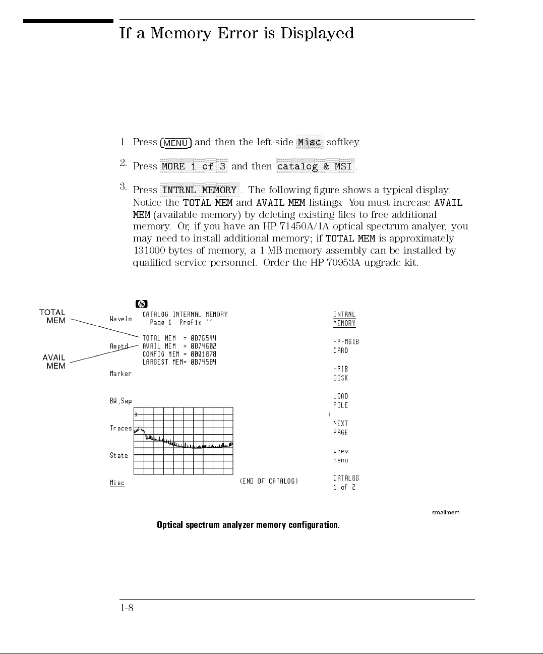
If a Memory Error is Displayed
1. Press
2.
3.
4
5
MENU
NNNNNNNNNNNNNNNNNNNNNNNNNNNNNNNNNNN
Press
MORE 1 of 3
and then the left-side
and then
Misc
softkey.
NNNNNNNNNNNNNNNNNNNNNNNNNNNNNNNNNNNNNNNNN
catalog & MSI
.
NNNNNNNNNNNNNNNNNNNNNNNNNNNNNNNNNNNNNNNNN
Press
INTRNL MEMORY
Notice the
MEM
TOTAL MEM
(available memory) by deleting existing les to free additional
. The following gure shows a typical display.
and
AVAIL MEM
listings.You must increase
AVAIL
memory.Or, if you have an HP 71450A/1A optical spectrum analyer,you
approximately
is
NNNNNNNNNNNNNN
need
may
131000
qualied
to
bytes
service
install
memory
of
personnel.
additional
1
a
,
memory;
memory
MB
Order
the
TOTAL
if
assembly
70953A
HP
MEM
can
upgrade
installed
be
kit.
by
1-8
spectrum analyzer memory conguration.
Optical
2
erforming
P
Measurements
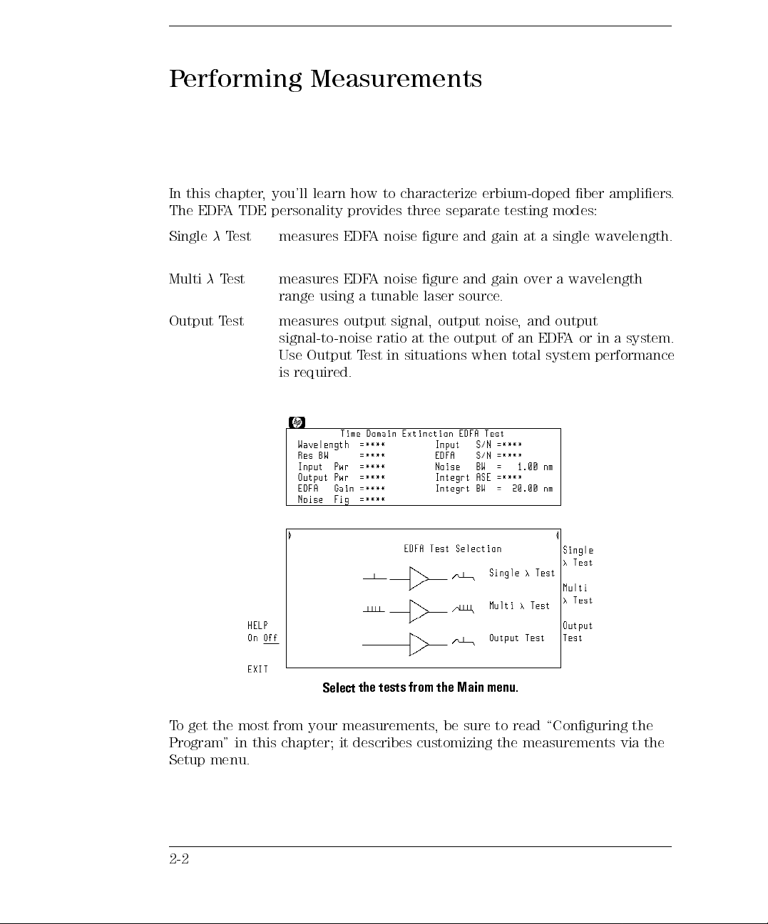
Performing Measurements
In this chapter, you'll learn how to characterize erbium-doped ber ampliers.
The EDFA TDE personality provides three separate testing modes:
SingleTest measures EDFA noise gure and gain at a single wavelength.
MultiTest measures EDFA noise gure and gain over a wavelength
range using a tunable laser source.
output
and
,
Output
est
T
measures
output
signal,
signal-to-noise ratio
in situations
Use Output
required.
is
Test
output
at the
noise
output of
when total
an EDF
system
in
or
A
performance
system.
a
menu.
Main
the
from
tests
the
Select
To get the most from your measurements
, be sure to read \Conguring the
Program" in this chapter; it describes customizing the measurements via the
Setup menu.
2-2
Chapter Contents
Performing Measurements
To ensure accurate measurements . . .
During calibrations and measurements, lightwave instrumentation and test setups are sensitive to
vibration and movement. To ensure accurate measurements avoid bumping, moving, or otherwise
jarring the instrument, test equipment, and supporting structure.
2-4
:
:
::
::
::
:
:
:
:
:
:
:
:
:
:
:
:
:
Calibrating
calibrate the
To
calibrate
o
T
perform
o
T
perform
o
T
perform
o
T
display
o
T
change
o
T
change
o
T
change
o
T
change
o
T
a
Running
Conguring
T
the
est
the
Optical
optical
HP 71450A/1A
an
::
::
:
:
single
a
multi
a
output
an
Program
values
noise
amplitude
the
peak
the
noise
the
ASE
the
Spectrum
spectrum
:
:
:
:
:
:
:
:
:
:
wavelength
wavelength
:
:
test
:
:
:
:
:
:
:
:
:
:
:
:
scale
excursion
bandwidth
integration
Analyzer
analyzer
..
..
:
:
:
:
:
test
test
:
:
:
::
:
:
:
:
:
:
:
:
:
:
:
:
:
value
:
:
window
:
2-5
..
.
.
.
.
.
.
.
.
.
.
.
.
.
.
.2-14
..
.
.
.
.
.
.
.
.
.
.
.
.
.
.
.
.
.
..
2-24
:
:
:
:
:
:
:
:
:
:
:
:
:
:
:
:
:
::
::
:
:
:
:
:
:
2-26
:
:
:
:
:
:
:
:
:
:
:
:
:
:
:
:
:
:
:
:
:
::
:
:
2-32
:
:
:
:
:
:
:
:
:
:
:
:
:
:
:
:
:
:
:
:
:
::
:
2-40
:
:
:
:
:
::
:
:
:
:
:
:
:
:
:
:
:
:
:
:
:
:
:
:
:
:
:
2-43
:
:
:
:
:
:
:
:
:
:
:
:
:
:
:
:
:
:
:
:
:
:
:
::
:
:
2-45
:
:
:
:
:
:
:
:
:
:
:
:
:
:
:
:
:
:
:
:
:
:
:
::
:
2-46
:
:
:
:
:
:
:
:
:
:
:
:
:
:
:
:
:
:
::
:
:
:
:
:
:
:
2-46
:
:
:
:
:
:
:
:
:
:
:
:
:
::
:
:
:
:
:
:
:
:
:
2-47
:
:
:
:
:
:
:
:
:
:
:
:
:
:
:
::
::
:
:
:
:
:
:
:
:
2-47
:
:
:
:
:
:
:
:
::
::
:
:
:
:
:
:
:
:
:
2-3

Guard
due
against
polarization
to
changes
Calibrating the Optical Spectrum Analyzer
Performing a user calibration on the optical spectrum analyzer
ensures maximum wavelength and amplitude accuracy for your EDFA
measurements. User calibrations require a stable (amplitude and wavelength)
single-frequency laser within the 600 to 1700 nm range.You can access the
Calibration menu from the optical spectrum analyzer's
4
5
MENU
and then
NNNNNNNNNNNNNNNNN
Amptd
.)
NNNNNNNNNNNNNNNNN
Amptd
menu. (Press
The optical spectrum analyzer's maximum calibration adjustment is about 2
Illegal
2023,
in wavelength.
nm
signal
Cal
Because
the
calibration
polarization
source's
light
ber-optic
optical
the
polarization,
If a
displayed.
is
optical spectrum
performed
optical
on
output
the
is
measured
be
power
power
disconnected
analyzer
should
cable
spectrum
larger adjustment
analyzer is
persons
by
measurements
measured
rst
is
the
from
Because
.
the
of
value
is attempted,
slightly
knowledgeable
During
.
with
power
moving
output
meter
ber-optic
power
error
polarization
calibration,
the
power
a
and
cables
vary
may
sensitive
eects
the
on
Then, the
.
meter
connected
changes
.
,
the
to
this
of
wavelength
a
Use
or optimum
F
within
results, perform
amplier's
the
the
calibration
range
a
at
wavelength
that
is
within
the
range
the
of
you are testing.
During a calibration, the optical spectrum analyzer defaults expect a signal within the following limits:
Power .........................................05dBm65dB
Wavelength ........................................130062nm
calibration
your
amplitude
enter the
must
ou
Y
wavelength
and
of
source
from these
dierent
is
it
if
values.
2-4
amplier
Performing Measurements
Calibrating the Optical Spectrum Analyzer
To calibrate the optical spectrum analyzer
Ensuring amplitude accuracy
During this procedure, avoid moving the ber-optic cables whenever possible. Moving ber-optic cables
changes the polarization of the light which aects power measurements.
source
Measure
the
wavelength
Measure the average
power
following
The
11896A
HP
The
optical
spectrum
71450A/1A"
Measure
1.
wavelength
The
the
the
procedure
the
is
analyzers
chapter
this
in
wavelength
the
meter
must
laser
optical
spectrum
wavelength
requires
suggested
perform
.
Enter
.
a
have
analyzer's
air
in
as
power
a
polarization
the
precision
a
of
wavelength
the
wavelength
monochromator
.
meter
controller
listed
steps
single-mode
in
between
and
in
the
600
polarization
a
or
F
.
calibrate
o
\T
laser
provided
space
1700
to
air
is
HP
lled,
controller
71450A/1A
an
a
using
nm.
measure
HP
below
Because
wavelength: nm
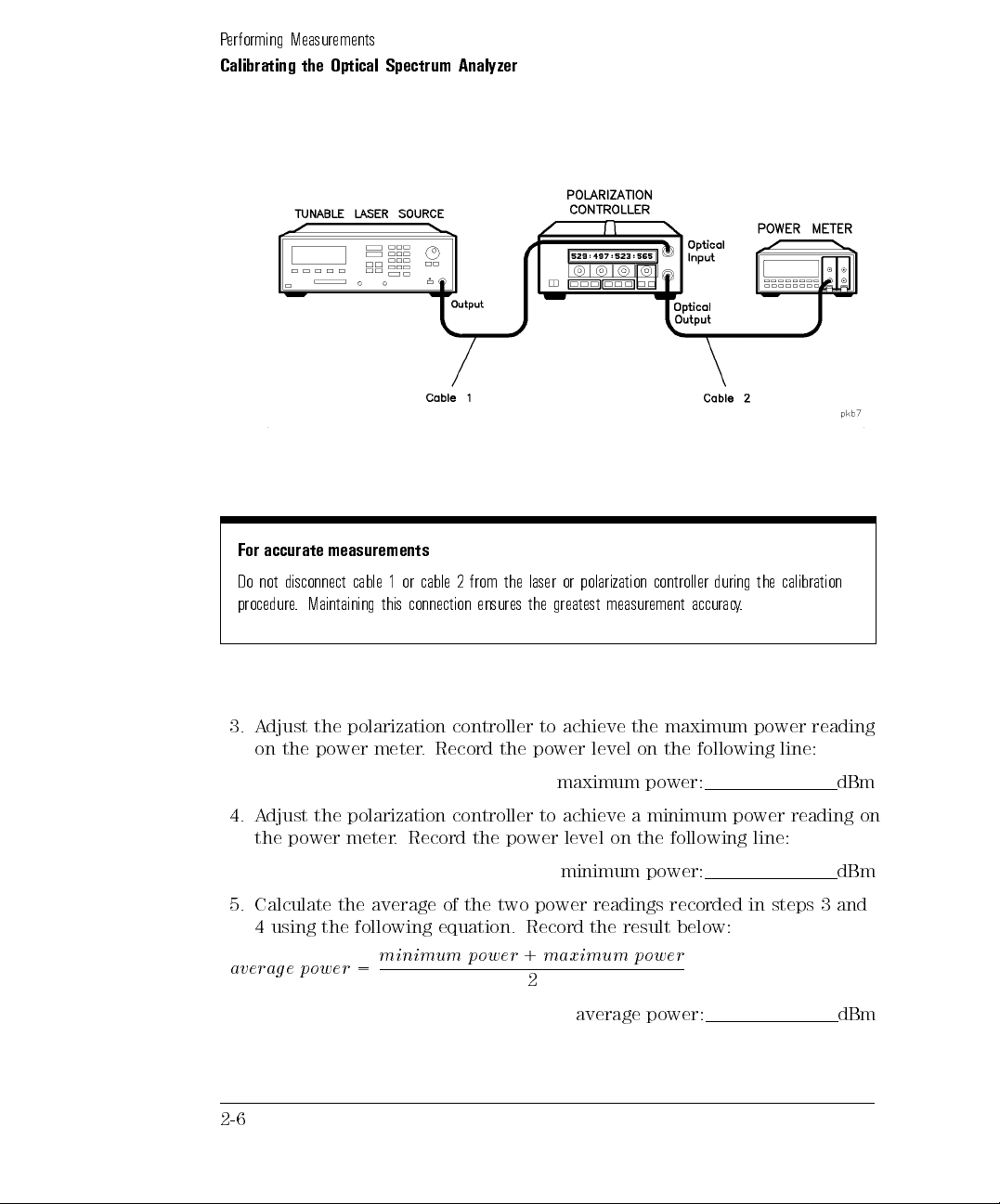
2. Connect the laser, polarization controller, and power meter as shown in
the following gure.
.
.
2-5
Performing Measurements
Calibrating the Optical Spectrum Analyzer
accurate
For
not
Do
procedure
Adjust
3.
on
measurements
disconnect
.
cable
Maintaining
the polarization
the power
or
1
connection
this
meter.
from
2
cable
ensures
controller to
Record the
the laser
the
power
polarization
or
greatest
achieve
level
controller
measurement
maximum
the
the
on
during
.
accuracy
following
calibration
the
power
line:
reading
maximum power: dBm
4. Adjust the polarization controller to achieve a minimum power reading on
the power meter. Record the power level on the following line:
minimum power: dBm
and
3
steps
Calculate
5.
the
using
4
averag e power
average
the
following
minimum power
=
the two
of
equation.
power
Record
+
readings
the result
maximum power
2
average
recorded
below:
power:
in
dBm
2-6
Performing Measurements
Calibrating the Optical Spectrum Analyzer
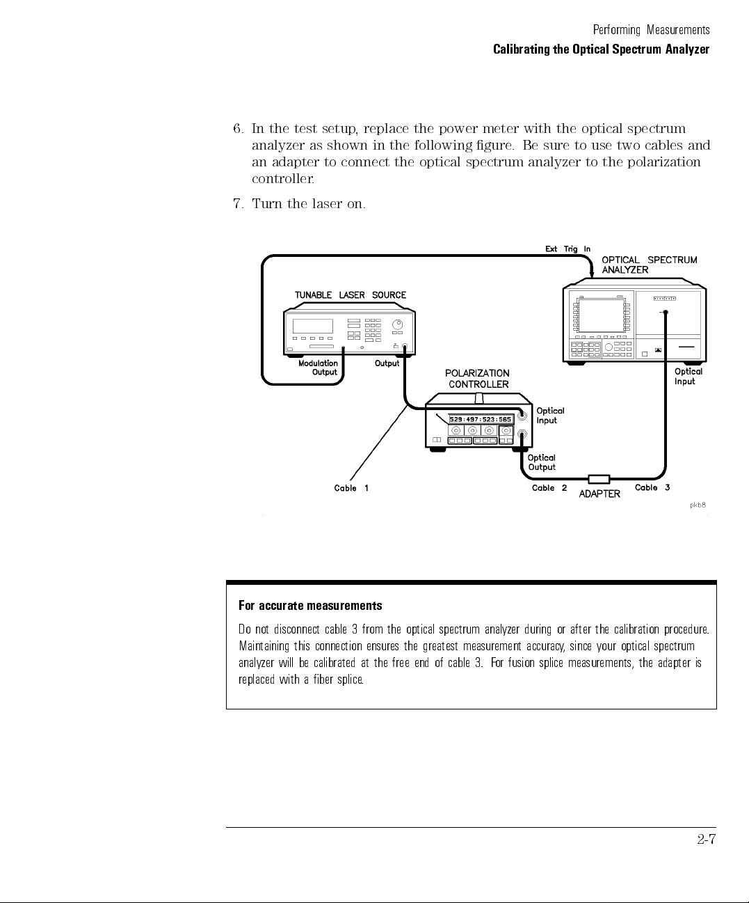
6. In the test setup, replace the power meter with the optical spectrum
analyzer as shown in the following gure. Be sure to use two cables and
an adapter to connect the optical spectrum analyzer to the polarization
controller.
7. Turn the laser on.
For accurate measurements
Do not disconnect cable 3 from the optical spectrum analyzer during or after the calibration procedure.
Maintaining this connection ensures the greatest measurement accuracy, since your optical spectrum
analyzer
replaced
be calibrated
will
aber
with
splice
splice measurements,
fusion
or
F
3.
cable
of
end
free
the
at
.
the
is
adapter
2-7
Performing Measurements
Calibrating the Optical Spectrum Analyzer
Determine correction
factor for source
spontaneous emission
8. Press
9. Press
10. Press
4
INSTR PRESET
4
AUTO MEAS
4
AUTO ALIGN
5
.
5
to display the laser's response.
5
to align the optical spectrum analyzer.
11. If the instrument you are calibrating has the Option 051 personality,
perform the following steps:
N
.
NNNNNNNNNNNNN
EDFA
to start the EDFA test personality.
a.
b.
Press
4
USER
NNNNNNNNNNNNNNNNNNNNNNNNNNNNNNNNNNN
Press
Output Test
5
and then
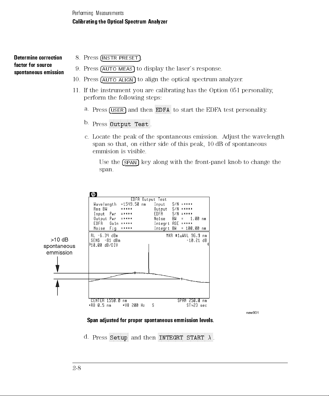
c. Locate the peak of the spontaneous emission. Adjust the wavelength
spontaneous
of
dB
10
peak,
this
of
side
either
on
that,
so
span
.
visible
the
is
change
to
4
SP
AN
5
key along
with
front-panel
the
knob
emmision
Use
span.
the
Span adjusted for proper
d.
Press
2-8
NNNNNNNNNNNNNNNNN
Setup
spontaneous emmission levels.
and then
NNNNNNNNNNNNNNNNNNNN
INTEGRT START
NNNNNNNNNNNNNNNNNNNNNNNNN
NN
.

Performing Measurements
Calibrating the Optical Spectrum Analyzer
e. Use the front-panel knob to move the left-integration marker to the
left edge of the display.
f.
NNNNNNNNNNNNNNNNNNNNNNNNNNNNNNNNNNNNNNNNNNNN
Press
INTEGRT STOP, and use the front-panel knob to move the
right-integration marker to the right edge of the display.
g.
h.
i. Subtract the
er
pow
1
the
Press
the
When
and
Integrt ASE
of
ratio
=
dB
)
(
left-side
measurement
two
the
utput
O
N
Measure
is complete
Amplr
softkey
, record
measurements on the following lines:
Output Pwr
Integrt ASE
Integrt ASE
power
r
w
P
(
dB
levels
)
m
from the
. Record
Integ
0
Output Pwr
result
the
E
AS
t
r
.
the displayed
: dBm
: dBm
to determine the
following
the
on
)
m
dB
(
Output Pwr
N
N
N
N
N
N
N
N
N
N
N
N
N
N
N
N
N
N
N
N
N
N
NN
NN
N
N
N
N
N
N
N
N
N
N
N
N
N
N
1 power: dB
12. If the instrument you are calibrating does not contain the Option 051
personality, perform the following steps:
a. Record the
value of the signal peak on the following line:
line:
2-9

Performing Measurements
Calibrating the Optical Spectrum Analyzer
b. Press
4
NORMAL On/O
Output Pwr
5
, and use the front-panel knob to place the
: dBm
marker on the maximum level of the spontaneous emission spectrum.
c.
NNNNNNNNNNNNNNNNNNN
N
Press
Marker
NNNNNNNN
On
is underlined.
NNNNNNNNNNNNNNNNNNNNNNNNNNNNNNNNNN
N
,
MORE 1 of 4
, and then
NNNNNNNNNNNNNNNNNNNNNNNNNNNNNNNNNNNNNNNNNNN
N
MKNOISE On Off
so that
d. Record the marker value on the following line:
e.
f.
g.
NNNNNNNNNNNNNNNNNNNNNNNNNNNNNNNNNNNNNNNNNNN
N
Press
MKNOISE On Off
N
N
N
N
N
N
N
N
N
N
N
Press
MORE 2
NN
NN
N
N
N
N
N
N
N
N
N
N
N
N
N
N
N
N
N
NN
NN
MKR BW
marker
Record
On Off
bandwidth
the
N
N
N
N
N
N
NN
NN
NN
N
N
N
N
of
N
N
N
N
N
N
N
N
N
N
N
N
NN
NN
displayed
N
N
N
N
N
N
N
N
,
4
so that
set
is
Marker
so that
NN
N
N
N
N
N
N
N
N
N
N
N
N
N
N
N
mkr bw/
N
N
N
N
NN
NN
On
0
to
MKR
NNNNNNNNNN
N
Off
is underlined.
N
N
N
N
N
N
N
N
N
N
N
N
N
N
N
N
N
N
N
NN
NN
zoom
underlined. Make
is
.
dB
3
Bandwidth
: dBm/nm
noise
N
NN
NN
NN
bw
,
and
then
sure that
value:
the
MKRBW: nm
record
and
,
BW
above
)
ASE
:
Calculate
h.
ASE
E
AS
(
on
dB
the
m
the
)
=
ASE
line
M
using
below:
R
K
noise
the
+
values
10
og
l
recorded
(
K
M
Integrt
R
the
dBm
log
ASE
of the
to
1
so that
to
the
0
Integrt
i. Subtract
to
the
1
power(dB)=Output P wr(dBm)0
j.
Press
the
Use
13.
broadband
the
determine
following
NNNNNNNNNNNNNNNNNNNNNNNNNNNNNNNNNNNNNNNN
N
the ratio
line:
MKR BW On Off
following
power
equation
meter
measurement:
f actor
=10
wherexis the 1 power recorded in step
2-10
from
12h)
(step
two power
levels.
Integrt ASE(dBm
NNNNNNNNNN
N
Off
is underlined.
correction factor
calculate
narrow
the
band
1
x
10
10
+1
11i or 12i.
the
Output
Record
Pwr
the
result
on
12a)
(step
)
1 power: dB
the
for
optical
spectrum
analyzer

Performing Measurements
Calibrating the Optical Spectrum Analyzer
source spontaneous emission correction factor: dB
Total the correction
factors
Calculate
power
Measure
power
corrected
level
the
OSA
on
average
14. Power meters generally are calibrated with an open beam of light. By
simply using a ber adapter, they will measure the optical power in
the beam emerging from the ber end. This is lower than the power in
the ber by 3.6%. If you wish to have power measurements relative to
open-beam power emerging from the ber, enter a correction factor of
+0.16 dB. If you wish to have power measurements relative to power in
the ber, enter 0 dB.
correction factor: dB
sign
the
of
track
keep
to
sure
Be
14.
and
13
steps
.
recorded
result
the
SEARCH
and
,
5
SEARCH
and enter
5
,
from
enter
in
the
on
then
and
5
wavelength
a
then
and
5
a wavelength
total correction
15
step
following
corrected
4
TO
4
TO
the
to
line
CENTER
span
CENTER
span of
average
.
power
.
5
1
of
.
5
0
factor:
power
level:
nm.
nm.
recorded
in
dd
15. A
each number
dd
A
16.
Record
5.
Press
17.
Press
18.
Press
19.
20. Press
the
the
4
4
4
4
values
value
PEAK
AN
SP
PEAK
AN
SP
of
dB
step
dBm
21. Press
22.
23.
24.
25.
26. A
4
5
.
MENU
NNNNNNNNNNNNNNNNN
Press the left-side
NNNNNNNNNNNNNNNNNNNNNNNNNNNNNNNN
Press
LOG dB/DIV,415
.
scale
left-side
the
Press
NNNNNNNNNNNNNNNN
Press
SWPTIME AutoMan
Amptd
N
N
NN
N
N
N
BW,Swp
NNNNNNNNNNNNNNNNNNNNNNNNN
,and
N
N
N
N
N
N
NNNNNN
softkey.
N
N
N
NN
N
N
,
NNNNNNNN
dB
to select a 1 dB logarithmic amplitude
softkey
.
NNNNN
4
5,4
5
1
, and then
0
s
.
djust the polarization controller to \peak" the trace displayed on the
optical spectrum analyzer
.
This sets the polarization for a maximum power reading.
2-11

Performing Measurements
Calibrating the Optical Spectrum Analyzer
27. Press
4
PEAK SEARCH
5
, and record the power level indicated by the marker:
maximum power: dBm
28. Press
415
.
29. Adjust the polarization controller to \dip" the trace displayed on the
optical spectrum analyzer to a minimum power value.
30. Record the absolute value of the 1 marker's power ratio on the following
line:
1 power: dBm
31. Use the values recorded in steps 27 and 30 to calculate the average
displayed
power
as
shown
in
following equation.
the
Record the
result
below:
er
pow
1
0
er
pow
N
N
N
N
N
N
softkey
N
N
N
N
N
N
N
N
N
N
N
N
N
N
N
N
N
N
N
controller
power level
NN
of
.
N
N
N
N
N
N
N
N
N
N
N
4
achieve
to
2
average
N
and
,
recorded
then
displayed
a
in
power:
N
N
N
N
N
N
N
N
N
N
N
N
N
N
N
N
A METER
31.
step
N
N
N
N
N
N
N
N
N
N
NN
N
N
N
N
N
On
Amplitude
N
N
N
N
N
Off
N
N
N
N
N
N
so
Meter
32.
33.
34.
er
av
Press
Press
that
Adjust
power
=
er
pow
e
ag
left-side
the
N
N
NN
N
N
N
N
N
N
N
N
N
N
N
N
N
N
N
N
N
N
N
N
N
MORE 1
N
N
N
N
NN
N
N
On
of
underlined.
is
the polarization
level equal
maximum
N
N
N
NN
N
N
N
N
N
Amptd
N
N
N
N
N
N
N
N
N
N
N
,
4
to the
N
N
MORE 2
Ensuring amplitude accuracy
It is very important not to move the ber-optic cables during the remaining steps of this procedure.
2-12

Performing Measurements
Calibrating the Optical Spectrum Analyzer
Enter the calibration
power and wavelength
35. Press the left-side
NNNNNNNNNNNNNNNNNNNNNNNNNN
cal menu
NNNNNNNNNNNNNNNNNNNNNNNNNNNNN
,
cal setup
NNNNNNNNNNNNNNNNNNNN
Waveln
, and then
softkey. Then, press
NNNNNNNNNNNNNNNNNNNNNNNNNNNNNNNNNNNNNNNNN
POWER FOR CAL
NNNNNNNNNNNNNNNNNNNNNNNNNNNNNNNNNNN
MORE 1 of 2
.
,
36. Use the numeric keypad to enter the corrected power level calculated in
step 16.
37.
NNNNNNNNNNNNNNNNNNNNNNNNNNNNNNNNNNNNNNNNNNNNNNN
Press
WAVELEN FOR CAL
Then, press
NNNNNNNNNNNNNNNNNNNNNNNNNNNNN
prev menu
. Enter the wavelength recorded in step 1.
and then
NNNNNNNNNNNNNNNNNNNNNNN
CAL ALL
.
2-13

Performing Measurements
Calibrating the Optical Spectrum Analyzer
To calibrate an HP 71450A/1A
Ensuring amplitude accuracy
During this procedure, avoid moving the ber-optic cables whenever possible. Moving ber-optic cables
changes the polarization of the light which aects power measurements.
ROM
Determine
the
version
Measure the source
wavelength
polarization
a
and
version
enter
to
N
NN
service
The
.
or
meter
on
N
N
N
N
N
N
N
N
N
N
N
version
above,
in \T
controller
used
is
instrument.
the
Miscellaneous
the
N
N
N
N
N
N
N
N
N
softkeys
of
not
do
o calibrate
.
select
to
.
ROM
the
perform
which
menu.
is
this
the
following
The
11896A
HP
The
optical
The
calibration
Press
1.
2.
Press
3.
Press
upper
the
the ROM
If
procedure
procedure
is
spectrum
procedure
left-side
the
N
N
N
N
N
N
NN
the
MORE
N
N
N
N
N
N
N
N
the
ROM
right
.
requires
suggested
the
analyzer's
should
N
N
N
N
N
N
Misc
NN
N
N
N
N
N
N
N
N
N
N
N
N
N
N
N
N
N
of
1
N
N
N
N
N
N
N
N
N
N
N
N
N
N
NN
NN
N
VERSION
corner
version is
Instead,
be
N
N
N
NN
N
N
N
softkey
N
N
N
N
N
N
N
N
and then
3
N
N
N
N
N
N
N
N
softkey
of the
B.05.00
perform
power
a
polarization
ROM
performed
display.
the steps
spectrum analyzer" in this chapter.
If the ROM version is
B.04.04
or below, continue with this procedure.
4. Measure the wavelength of a precision single-mode laser using a
wavelength
laser
The
meter
must
Enter
.
have
wavelength
the
wavelength
a
in
between
600 to
1700
nm.
provided
space
the
the optical spectrum analyzer's monochromator is air lled, measure
the wavelength as in air
.
controller
displayed
optical
below
Because
.
in
.
2-14
wavelength: nm

Performing Measurements
Calibrating the Optical Spectrum Analyzer
Measure the average
power
5. Connect the laser, polarization controller, and power meter as shown in
the following gure.
accurate
For
not
Do
procedure
measurements
disconnect
Maintaining
.
cable
this
or
1
2
cable
connection
from
ensures
the
laser
the
greatest
or polarization
measurement
controller
accurac
during
y
.
the
calibration
6. Adjust the polarization controller to achieve the maximum power reading
on the power meter. Record the power level on the following line:
maximum power: dBm
7.
djust
A
the
the
power
polarization
Record
.
meter
controller
power
the
achieve a
to
level on
minimum
following
the
power
line:
reading
on
minimum power: dBm
8. Calculate the average
7 using the following equation. Record
minimum power
averag e power
=
of the two power readings recorded in steps 6 and
the result below:
+
maximum power
2
2-15

Performing Measurements
Calibrating the Optical Spectrum Analyzer
average power: dBm
9. In the test setup, replace the power meter with the optical spectrum
analyzer as shown in the following gure. Be sure to use two cables and
an adapter to connect the optical spectrum analyzer to the polarization
controller.
10. Turn the laser on.
For accurate measurements
Do not disconnect cable 3 from the optical spectrum analyzer during or after the calibration procedure.
optical spectrum
your
since
,
y
or fusion
F
accurac
splice
measurements,
the
adapter
Maintaining this
analyzer will
be
replaced with
connection
calibrated
ber
a
splice
ensures
the
at
.
free
the
greatest
end
cable
of
measurement
3.
2-16
is

Performing Measurements
Calibrating the Optical Spectrum Analyzer
Determine correction
factor for 0.2 nm RBW
11. Press
12. Press
13. Press
4
AUTO MEAS
4
AUTO ALIGN
4
RES BW
5
, and enter a 0.2 nm bandwidth.
5
to display the laser's response.
5
to align the optical spectrum analyzer.
14. Record the source amplitude on the following line:
power (0.2 nm RBW): dBm
15. Press
4
RES BW
5
, and enter a 0.5 nm bandwidth.
16. Record the source amplitude on the following line:
power (0.5 nm RBW): dBm
reading
the
from
16
step
17.
cor
N
This
Subtract
the result
ection
r
E
T
O
number
the
on the
actor
f
should be
reading
in
following line:
E
W
O
P
=
between 0
dB
R
0.2
and
step
nm
0
14
0.2
0
RB
dB
P
W
.
R
E
W
O
correction
step
16
factor:
in
step
14
and
record
dB
Determine correction
factor for source
spontaneous emission
18. Press
4
INSTR PRESET
5
.
19. If the instrument you are calibrating has the Option 051 personality,
perform the following steps:
N
N
N
NN
N
N
N
N
N
N
N
N
a.
b.
Press
Press
4
5
USER
N
N
N
N
N
N
N
N
N
N
N
NN
Output
and then
N
N
N
N
N
N
N
N
N
NN
Test
c. Locate the peak of the spontaneous emission. A
N
to start
EDFA
N
N
N
N
N
N
N
N
NN
N
the
personality
test
A
EDF
.
.
djust the wavelength
span so that, on either side of this peak, 10 dB of spontaneous
emmision
is visible.
2-17

Performing Measurements
Calibrating the Optical Spectrum Analyzer
Span
d.
Use the
span.
adjusted
Press
N
N
N
N
N
N
NN
NN
Setup
4
SPAN
for
N
N
N
N
5
key along with the front-panel knob to change the
N
N
N
N
N
N
N
N
N
NN
NN
N
N
START
levels.
N
N
N
N
N
N
N
N
N
N
N
N
N
N
.
proper
N
N
N
,
spontaneous
then
and
emmission
N
N
N
N
N
N
N
N
N
N
N
N
NN
NN
INTEGRT
N
N
2-18
e.
Use the
front-panel knob
to
left-integration
the
move
left edge of the display.
f.
NNNNNNNNNNNNNNNNNNNNNNNNNNNNNNNNNNNNNNNNNNNN
Press
INTEGRT STOP, and use the front-panel knob to move the
right-integration marker to the right edge of the display.
marker
to
the

g.
Press
NN
N
N
N
N
N
N
N
N
N
N
N
N
N
N
N
Measure
N
N
N
N
N
N
N
N
N
Amplr
Performing Measurements
Calibrating the Optical Spectrum Analyzer
N
N
N
N
N
N
N
N
N
N
N
N
N
N
N
.
measurement
the
When
h.
measurements
Integrt
power
two
ASE
ASE
levels
Integrt
and
Pwr
Subtract the
i.
of the
ratio
1
power(dB)=Output P wr(dBm)0
completed,
is
Integrt
the
from
Record
.
Integ rt AS E(dBm
record
the
on
Output
Output
the
the
following
Pwr
ASE
Pwr
result
displayed
:
:
determine
to
the
on
)
Output
lines:
the
following
1 power: dB
20. If the instrument you are calibrating does not contain the Option 051
personality,
a. Record
b. Press
4
NORMAL On/O
perform
value
the
following
the
signal
the
of
5
, and use the front-panel knob to place the
steps:
peak
following
the
on
Output Pwr
line:
:
marker on the maximum level of the spontaneous emission spectrum.
dBm
dBm
line:
dBm
2-19

Performing Measurements
Calibrating the Optical Spectrum Analyzer
c.
NNNNNNNNNNNNNNNNNNNN
Press
Marker
NNNNNNNN
On
is underlined.
NNNNNNNNNNNNNNNNNNNNNNNNNNNNNNNNNNN
,
MORE 1 of 4
, and then
NNNNNNNNNNNNNNNNNNNNNNNNNNNNNNNNNNNNNNNNNNNN
MKNOISE On Off
d. Record the marker value on the following line:
MKR
e.
f.
NNNNNNNNNNNNNNNNNNNNNNNNNNNNNNNNNNNNNNNNNNNN
Press
MKNOISE On Off
NNNNNNNNNNNNNNNNNNNNNNNNNNNNNNNNNNN
Press
MORE 2 of 4
NNNNNNNNNNNNNNNNNNNNNNNNNNNNNNNNNNNNNNNNN
MKR BW On Off
so that
NNNNNNNNNNNNNNNNNNNNNNNNNNNNNNNNNNNNNNNNNNNNNNN
,
mkr bw/ zoom bw
so that
NNNNNNNN
On
is underlined. Make sure that the
NNNNNNNNNNN
Off
noise
is underlined.
, and then
marker bandwidth is set to03dB.
Record the
g.
displayed
Marker
Bandwidth
value:
MKRBW: nm
og
l
recorded
(
K
M
)
R
W
B
Calculate
h.
ASE
E
AS
(
on
dB
the
m
the
)
=
ASE
line
M
using
below:
R
K
noise
the
+
values
10
Integrt
the
from
12i)
(step
ratio
ASE
of
the
two
power
levels
Subtract
i.
to
the
the
determine
following
Integrt
the
line:
so that
: dBm/nm
record the
and
,
above
:
ASE
Output
Record
.
Pwr
the
(step
result
dBm
12a)
on
Output
=
)
dB
(
er
pow
1
NN
NN
N
N
N
N
j.
N
Press
MKR BW On Off
Pw
power:
1
N
N
N
N
N
NN
NN
NN
N
N
N
N
N
N
N
N
N
N
N
N
N
N
N
N
N
N
N
NN
so that
NN
NN
NN
N
N
N
N
N
Off
is underlined.
)
m
dB
(
E
AS
t
r
nteg
I
0
)
m
dB
(
r
21. Use the following equation to calculate the correction factor for the
broadband power meter to the narrow band optical spectrum analyzer
measurement:
actor
f
=
10
og
l
0
1
10
10
x
1
+1
wherexis the 1 power recorded in step 19i or 20i.
source spontaneous emission correction factor: dB
2-20
dB

Performing Measurements
Calibrating the Optical Spectrum Analyzer
Total the correction
factors
Calculate
power
Measure
power
corrected
level
the
OSA
on
average
22. Power meters generally are calibrated with an open beam of light. By
simply using a ber adapter, they will measure the optical power in
the beam emerging from the ber end. This is lower than the power in
the ber by 3.6%. If you wish to have power measurements relative to
open-beam power emerging from the ber, enter a correction factor of
+0.16 dB. If you wish to have power measurements relative to power in
the ber, enter 0 dB.
correction factor: dB
23. Add the values from steps 17, 21, and 22. Be sure to keep track of the
sign of each number.
factor:
step
power
recorded
in
level:
.
nm.
1
of
.
nm.
0
of
dd
A
24.
Record
8.
Press
25.
Press
26.
Press
27.
28. Press
the
4
4
4
4
value
PEAK
AN
SP
PEAK
AN
SP
the
SEARCH
and
,
5
SEARCH
and
5
,
recorded
on
result
and
5
enter
and
5
enter
23
step
in
following
the
corrected
4
then
TO
wavelength
a
4
then
TO
wavelength
a
total
to
CENTER
CENTER
correction
average
the
.
line
power
5
span
5
span
dB
dBm
29. Press
30.
31.
4
MENU
the
Press
NNNNNNNNNNNNNNNNNNNNNNNNNNNNNNNN
Press
LOG dB/DIV,415
5
.
left-side
NN
NN
NN
N
N
N
N
Amptd
N
N
N
N
N
NN
softkey
,and
.
NNNNNNNN
dB
to select a 1 dB logarithmic amplitude
scale.
NNNNNNNNNNNNNNNNNNNN
32. Press the left-side
N
N
N
N
N
N
N
NN
N
N
N
N
N
33.
34. A
N
Press
SWPTIME
djust the polarization controller
optical spectrum analyzer
N
N
N
NN
N
N
N
BW,Swp
N
N
N
N
N
NN
N
N
N
N
N
N
N
N
AutoMan
N
N
N
N
N
N
N
NN
,
.
softkey.
4
4
,
5
5
1
0
,
and
then
to \peak" the trace displayed on the
This sets the polarization for a maximum power reading.
35. Press
4
PEAK SEARCH
5
record the power level indicated by the marker:
,and
N
N
N
N
N
.
s
2-21

Performing Measurements
Calibrating the Optical Spectrum Analyzer
maximum power: dBm
36. Press
415
.
37. Adjust the polarization controller to \dip" the trace displayed on the
optical spectrum analyzer to a minimum power value.
38. Record the absolute value of the 1 marker's power ratio on the following
line:
1 power: dBm
39. Use the values recorded in steps 35 and 38 to calculate the average
displayed power as shown in the following equation. Record the result
below:
power
1
0
er
pow
N
N
NN
NN
softkey
N
N
N
N
N
N
N
N
N
N
N
N
N
N
N
N
NN
N
2
controller
power
N
N
N
N
N
N
of
level
.
N
N
N
NN
N
4
to
average
N
N
and
,
achieve
recorded
2
N
N
then
A
a displayed
in step
power:
N
N
N
N
N
N
N
NN
N
METER
N
On
Off
N
N
N
N
N
N
N
N
N
N
NN
N
N
N
N
N
N
N
N
N
N
N
N
N
N
N
Amplitude Meter
39.
N
N
N
N
so
40.
41.
42.
aver
Press
Press
that
djust
A
power
age
the
N
N
MORE
N
N
N
N
N
On
N
NN
N
N
N
N
the
level
power
left-side
N
of
1
underlined.
is
N
N
N
N
N
N
N
N
N
N
N
N
N
N
N
N
N
polarization
equal
=
maximum
N
N
N
N
N
N
N
N
Amptd
N
N
N
N
N
NN
N
N
N
N
,
4
the
to
N
N
N
N
N
MORE
Ensuring
amplitude
accuracy
It is very important not to move the ber-optic cables during the remaining steps of this procedure.
2-22

Performing Measurements
Calibrating the Optical Spectrum Analyzer
Enter the calibration
power and wavelength
43. Press the left-side
NNNNNNNNNNNNNNNNNNNNNNNNNN
cal menu
NNNNNNNNNNNNNNNNNNNNNNNNNNNNN
,
cal setup
NNNNNNNNNNNNNNNNNNNN
Waveln
, and then
softkey. Then, press
NNNNNNNNNNNNNNNNNNNNNNNNNNNNNNNNNNNNNNNNN
POWER FOR CAL
NNNNNNNNNNNNNNNNNNNNNNNNNNNNNNNNNNN
MORE 1 of 2
.
,
44. Use the numeric keypad to enter the corrected power level calculated in
step 24.
45.
NNNNNNNNNNNNNNNNNNNNNNNNNNNNNNNNNNNNNNNNNNNNNNN
Press
WAVELEN FOR CAL
Then, press
NNNNNNNNNNNNNNNNNNNNNNNNNNNNN
prev menu
. Enter the wavelength recorded in step 4.
and then
NNNNNNNNNNNNNNNNNNNNNNN
CAL ALL
.
2-23

Running a Test
Each testing mode displays messages that guide you through the correct
measurement sequence. Generally, the source's output is measured, and then
the amplier's output is measured. (The exception is the Output Test which
does not measure the source.) You can disable these prompts at any time by
pressing
obscures the view of the trace, remove the prompt by pressing
Using the EDFA TDE personality requires the following test setup.
NNNNNNNNNNNNNNNNNNNNNNNNNNNNNNNNNNNNNNNNN
PROMPT On Off
so that
NNNNNNNNNNN
Off
is underlined. If a prompt message
4
HOLD
5
.
2-24

Performing Measurements
Running a Test
Set the laser for the
desired average power
level
The EDFA TDE personality measures the average ASE power level resulting
from a modulated laser's average power. Before you begin testing an EDFA,
determine the average power level of the laser input desired for your
application. Next, set the test laser's unmodulated power level 3 dB higher
than this level. For example, if the modulated laser's power into the amplier
is010 dBm, set your test laser's output power to07 dBm. When modulated
at the 50% duty cycle, the test laser's power will be equal to the level used in
your application.
The following gure shows the timing required to measure the average ASE
value from an input laser saturating the EDFA. The laser is modulated at a 25
kHz rate and 50% duty cycle. In this example, the laser's average power is
dBm
8
0
the data
laser's o
the gure
in
see
decreases
and
average
the
.
laser
dBm
8
0
(
s after
10
cycle and
when the
ASE
=
, the
level
dBm
5
0
the laser
in the
region where
power
ASE
laser turns
for the
3
0
turned
is
given
dB).
level
on.
The
o.
the
increases
Measuring
average
optical
This
ASE
input
spectrum
point
varies
when
the
power
analyzer samples
way
half
is
laser
of
.
is
10
at
modulated
the
linearly
the
ASE
through
you
As
turned
provides
s
the
can
o
Measurement timing diagram.
2-25

Performing Measurements
Running a Test
To perform a single wavelength test
The following measurements are made in this test:
Wavelength
EDFAgain
Noise gure
Input power
Output power
Input S/N
A S/N
EDF
Integrated
ASE
Procedure
Connect
1.
shown in
cables that
will be
from the
On HP
labeled
the
triggering
and
70950B/1B/2B
the
output
the
following
the
were
when
used
or
laser
71450B/2B
OPTICAL
connector
input
requires
maximum
a
71450B/1B/2B
HP
the
of
in
used
EDF
the
optical
optical
INPUT
is
a
+5V
of
modules
the
to
laser
adapter
The
.
gure
calibration
the
inserted.
is
A
spectrum
analyzer
spectrum
71451B
HP
On
.
labeled
MONOCHROMATOR
TTL-compatible
more information
or
F
.
\Triggering
to
refer
,
Optical
Spectrum
optical
allows
procedure
not
Do
during
analyzers
optical
signal
Analyzers
you
These
.
analyzer
use
to
same
spectrum
disconnect
test.
the
connector
input
the
,
spectrum analyzers
External
.
INPUT
minimum
a
with
on triggering
Sweeps" in
Chapter 2
User's Guide
the
these
of 0V
the
as
same
cables
cables
is
,
HP
of
.
2-26

Performing Measurements
Running a Test
2.
3.
Turn
Do
Press
a.
on
the
the laser
following
the
.
steps
front-panel
to congure
4
VELENGTH
A
W
the
5
wavelength.
b.
c.
d.
Press
Press
oggle
T
N
N
N
N
N
N
N
N
N
N
Power
the
OUTPUT
N
N
N
N
N
N
N
N
N
N
N
N
N
N
Mod/CW
NN
N
N
the
Freq
N
N
N
N
N
N
N
(frequency is
N
N
N
N
N
NN
NN
N
to
N
N
N
N
NN
WER
PO
turn the
N
N
NN
NN
NN
NN
N
N
/
Power
selected).
N
N
N
N
N
and
,
key
5
modulation
softkey
so
4
e. Enter a modulation value of 25 kHz.
4. On the optical spectrum analyzer, press
5.
Press
4
USER
5
and
then
NNNNNNNNNNNNNNNNNNNNNNN
EDFA_TD
to
start
8168A/B/C
HP
and
,
key
the
enter
on.
the
that
4
AUTO MEAS
EDF
the
enter
source
softkey
5
.
TDE
A
laser:
the desired
.
power
label reads
personality
.
2-27

Performing Measurements
Running a Test
6.
7.
NNNNNNNNNNNNNNNNNNNNNNNNNNNNNNNNNNNNNNNNN
Press
SingleTest
Enter
the
spectrum
the
erform
P
optical
a.
following
analyzer:
4
5
ART
ST
.
you
if
steps
wavelength.
need
change the
to
tuning
range
of
the
4
the
Enter
8.
b.
c.
HOLD
4
Press
NNNNNNNNNNNNNNNNNNNNNNNNNNNNNNNNNNNNNNNNNNNN
Press
Measure Source
STOP
.
5
wavelength.
5
.
The EDFA TDE personality measures the signal and noise levels at the
end of the sweep.
2-28

Performing Measurements
Running a Test
9.
Allow at least one complete measurement cycle. Then, press
source.
laser
the
Measurement
of
NNNNNNNNNNNNNN
DONE
.
Using
Until
N
N
N
N
N
N
N
N
N
N
you
N
N
the
NN
N
press
NN
NN
\SINGLE
N
NN
SWEEP"
N
N
N
N
N
the
DONE
N
N
N
N
N
N
N
N
N
N
N
N
N
N
N
N
SINGLE SWEEP
measurement. For each measurement,
and
N
NN
NN
NN
N
N
softke
N
N
N
N
N
N
N
N
N
and
CONT SWEEP
y
NN
NN
N
N
N
N
N
N
N
N
N
N
N
N
N
N
N
NN
NN
continuously
test
the
,
NNNNNNNNNNNNNNNNNNNNNNNNNNNNNNNNNNNNNN
SINGLE SWEEP
measures
the
The
signal.
input
softkeys allow you to manually step through a
must be pressed three times. The rst
SWEEP" softkeys
\CONT
press measures the wavelength using a smoothed peak in a wide wavelength span (indicated by a blue
line). The second press measures the amplitude of the smoothed peak in a narrow wavelength span.
The third press measures the noise at wavelength of the signal in a wide wavelength span (indicated
line).
red
ya
b
N
N
N
N
N
N
NN
N
N
N
N
N
N
N
N
N
N
N
NN
N
N
N
N
N
N
N
N
N
N
The
N
CONT
SWEEP
softke
ygives
you
the
ability
to
return
automated
to
testing.
2-29

Performing Measurements
Running a Test
10. Remove the adapter, and connect the EDFA as shown in the following
gure.
11.
2-30
Press
display
N
N
N
N
N
N
N
N
N
N
N
N
NN
N
N
N
Measure
all
lists
N
N
N
N
N
N
N
the
NN
N
N
N
N
Amplfr
N
N
N
N
N
N
N
N
N
N
N
N
N
N
.
After
measurement
the
results
rst
complete
top
the
at
sweep occurs
screen.
the
of
,
the

12.
When
you
are
nished
with
measuring
the
amplier
Performing Measurements
Running a Test
N
N
N
N
N
N
N
N
N
N
N
N
N
N
press
,
DONE
.
2-31

Performing Measurements
Running a Test
To perform a multi wavelength test
The following procedure is meant to be used with an
HP 8168A/B/C tunable laser source. Other sources can be used as
explained in the procedure. In this example, the following settings are used:
Procedure
Start wavelength
Stop wavelength
Step size
::::: ::::::::: ::::::: ::::::::: :::::: ::::::::: ::::::: ::::::::: :
:::::: ::::::::: ::::::: ::::::::: :::::: ::::::::: ::::
::::: ::::::::: ::::::: ::::::::: :::::: ::::::::: :::::
These settings are for example only.You can use any valid range.
source
in
be
from
INPUT
laser
following
the
that
used
the
the
,
spectrum
were
when
laser
input
.
used
or
connector
analyzers
output
Connect
1.
optical
The
the
spectrum
adapter
allows
calibration procedure
is inserted.
Do
spectrum analyzer
On HP
labeled
input
71450B/2B
OPTICAL
connector
of
analyzer's
you
.
disconnect
not
.
optical
INPUT
labeled
is
8168A/B/C
HP
the
input
the
use
to
same
These
these
spectrum
On
.
MONOCHROMATOR
HP
shown
as
same
cables
cables
analyzers
71451B
tunable
cables
will
optical
to
gure
in
the
optical
1540 nm
1560 nm
2nm
the
.
the
A
EDF
is
the
,
2-32

Performing Measurements
Running a Test
Select the test
2. Press
3. Press
Do
4.
rate:
4
5
and then
USER
NNNNNNNNNNNNNNNNNNNNNNNNNNNNNNNNNNNNNN
MultiTest
following
the
NNNNNNNNNNNNNNNNNNNNNNN
EDFA_TD
.
steps to
to start the EDFA TDE personality.
modulate the
8168A/B/C
HP
laser
at
kHz
25
a
the
a.
b.
Press
Press
4
OUTPUT PO
N
N
N
N
N
N
N
N
N
N
N
N
N
N
Mod/CW
WER
N
N
N
N
N
N
to turn the modulation on (
displayed).
c.
Toggle the
NNNNNNNNNNNNNNNN
N
Power
Enter
d.
NNNNNNNNNNNNN
N
Freq
.
modulation
a
NNNNNNNNNNNNNNNN
N
/
Power
value
5. On the HP 8168A/B/C, press
wavelength settings
step
. In this case 1540 nm, 1560 nm, and 2 nm
respectively.
6. Turn the laser on.
7. On the HP 8168A/B/C, press
.
key
5
POWER
and
FREQ
are
softkey so that the softkey label reads
kHz.
of 25
N
N
N
N
NN
N
-Sweep
NNNNNNNNNNNNNN
Manual
N
N
N
N
N
N
N
NN
N
N
N
N
N
N
N
, and enter the
start, stop
,and
NNNNNN
.
2-33

Performing Measurements
Running a Test
8. On the optical spectrum analyzer, enter the start and stop wavelength
settings:
4
5
START
4
STOP
NOTE
The start wavelength should be visible on the optical spectrum anayzer's display. In relatively narrow
spans, as in this example, set the span slightly wider than the laser's tuning range. This ensures that
the start and stop wavelengths can be identied during testing.
:::::: ::::::::: ::::::: ::::::::: ::::::: ::::::::: :::::: ::
5
:::::: ::::::::: :::::: ::::::::: ::::::: ::::::::: :::::: ::::
1539 nm
1561 nm
9. On the optical spectrum analyzer
2-34
, press
4
HOLD
5
.

Performing Measurements
Running a Test
Measure the source
10. Press the left-side
Measure Source
softkey.
11. Repeat the following steps for each wavelength to be measured:
NNNNNNNNNNNNNNNNNNNNNNNNNNNNNNNNNNNNNNNNNNNN
a.
b.
c.
NNNNNNNNNNNNNNNNNNNNNNNNNNNNNNNN
Press
TAKE SWEEP
Wait until the
NNNNNNNNNNNNNN
Press
Next
on the optical spectrum analyzer.
NNNNNNNNNNNNNNNNNNNNNNNNNNNNNNNN
TAKE SWEEP
softkey is no longer highlighted.
on the HP 8168A/B/C to tune the laser to the next
wavelength.
F
F
F
F
F
F
F
F
F
F
F
FF
FF
FF
FF
F
F
F
TAKE SWEEP
F
F
F
F
F
F
F
pressed. First wavelength measured.
test
Restarting
ou
Y
clears an
the
testing
restart
can
y previously measured data points.
at an
wavelengths
All
pressing
and
laser
resetting
y
b
time
y
the
measured.
N
NN
N
N
N
N
N
N
N
N
N
N
N
NN
Measure
N
N
N
N
N
N
N
N
N
N
N
N
N
NN
N
N
N
Source
N
N
N
N
NN
N
N
N
N
This
.
2-35

Performing Measurements
Running a Test
12. Press
Using the \SINGLE SWEEP" and \CONT SWEEP" softkeys
When you press
signal. The
To characterize a wavelength manually,
DONE
after all the wavelengths are captured.
NNNNNNNNNNNNNNNNNNNNNNNNNNNNNNNN
TAKE SWEEP
NNNNNNNNNNNNNNNNNNNNNNNNNNNNNNNNNNNNNN
SINGLE SWEEP
, a measurement routine takes three sweeps to characterize the
softkey allows you to manually step through each of these sweeps.
NNNNNNNNNNNNNNNNNNNNNNNNNNNNNNNNNNNNNN
SINGLE SWEEP
must be pressed three times. The rst
press measures the wavelength using a smoothed peak in a wide wavelength span (indicated byablue
line). The second press measures the amplitude of the smoothed peak in a narrow wavelength span.
(indicated
NNNNNNNNNNNNNN
routine
span
repeats
press
third
The
red
a
y
b
the
When
continuously until
N
N
N
N
N
N
N
N
N
N
NN
NN
N
N
TAKE
13. On
the HP
press
line).
N
N
N
N
N
N
N
N
N
CONT
N
N
N
N
N
N
N
N
N
N
N
SWEEP
noise
measures
o
T
N
N
NN
the
automated
to
return
N
N
N
N
N
N
N
N
N
N
N
NN
NN
NN
NN
N
N
SWEEP
N
N
N
N
N
N
SINGLE SWEEP
N
NN
softke
NN
N
N
N
N
N
N
N
N
N
N
N
N
N
N
N
.
8168A/B/C,
N
NN
at
y
N
N
N
N
N
N
press
wavelength
testing,
pressed,
is
N
N
N
N
N
N
is pressed.
N
press
N
N
N
N
N
N
N
N
Stop
of
the
N
N
N
N
N
and
signal
the
N
N
NN
NN
NN
N
N
N
N
N
N
N
TAKE
three-sweep
return
o
T
then
wide
a
in
N
N
N
N
N
N
N
N
N
N
N
N
SWEEP
measurement
automated
to
N
N
N
N
N
N
N
Manual
N
N
N
N
N
.
N
N
N
N
N
N
N
wavelength
testing,
N
N
N
N
N
N
.
14.
2-36
Remove
.
gure
the
adapter
,
and
connect
the
EDF
shown
as
A
in the
following

Performing Measurements
Running a Test
Measure
the
amplier
15.
16.
N
N
N
N
Press
Measure
Repeat
a.
Press
b.
ait
W
c.
Press
wavelength.
N
N
N
N
N
N
the
N
N
N
TAKE
until
N
N
N
Next
N
N
N
N
N
N
N
N
N
N
N
N
N
N
N
N
N
NN
Amplfr
following
N
N
N
N
N
N
N
N
N
N
NN
N
N
N
N
SWEEP
the
N
NN
NN
NN
NN
N
on
N
N
N
N
N
N
N
N
N
N
N
N
N
N
N
N
N
N
NN
N
TAKE
the
N
NN
N
N
N
steps
N
N
N
N
N
N
N
N
N
N
N
N
N
HP
N
N
N
.
for
the
on
NN
NN
N
N
N
N
N
N
N
N
N
N
SWEEP
8168A/B/C
each
optical
N
N
N
N
softkey
wavelength
spectrum
longer highlighted.
is no
tune
to
to
analyzer
laser
the
measured:
be
.
to the
next
2-37

F
F
F
F
F
F
TAKE
F
F
FF
F
F
F
F
F
F
F
F
F
F
FF
SWEEP
Performing Measurements
Running a Test
F
F
F
F
F
F
F
pressed.
First
wavelength
measured.
All wavelengths
measured.
the
Display
measurement
results
test
Restarting
ou
Y
clears
17. Press
Press
18.
19.
Press the right-side
20. Select
the
at
testing
restart
can
y
an
previously
N
N
NNNNNNNNNNNNN
DONE
N
Display
measured
after all the wavelengths are captured.
NN
N
N
N
N
N
N
N
N
N
N
N
NN
N
N
N
N
N
N
N
N
N
Data
from one of the displayed softkeys to view a trace of measurement
data versus wavelength. F
21.
Press
NNNNNNNNNNNNNNNNN
AUTO
NNNNNNNNNNNNNNN
SCALE
2-38
y
b
time
y
an
points.
data
NN
N
N
N
N
N
N
N
N
N
N
to
N
N
N
N
N
N
NN
N
N
view traces
N
N
N
N
data select
resetting
N
the
of
N
N
N
N
N
N
NN
N
N
N
N
N
N
N
N
N
N
NN
softkey.
or this example
measurement
, press
pressing
and
laser
to automatically scale the traces
N
Measure
Amplfr
N
N
N
N
N
N
N
N
N
N
N
N
N
NN
NN
N
N
N
N
N
N
N
N
N
N
N
data.
NNNNNNNNNNNNNNNNNNNNNNNNN
NNNNNNN
GAIN and NF
.
N
N
N
NN
NN
N
N
N
N
N
N
N
N
This
.
NNN
.

Gain
and
noise
gure
versus
Performing Measurements
Running a Test
wavelength.
matches
Color
that
Notice
22. If you want to manually scale the display, use
trace
measurement
the
values
change
color to
match the
displa
the
of
color
NNNNNNNNNNNNNNNNNNNNNNNNNNNNNNN
N
LOG dB/DIV
yed
measurement
and
front-panel knob, step keys, or numeric keypad to enter a new value.
23. Press
4
NORMAL ON/OFF
marker
.
display shows
The
5
, and turn the front-panel knob to move the
marker
the
the
data
measured
at
.
trace
. Use the
wavelength.
2-39

Performing Measurements
Running a Test
To perform an output test
During the output test, the source is not characterized. The measurements
performed include the following:
Output wavelength and power
Output noise
Output signal-to-noise ratio
Procedure
1. Connect the system with the EDFA to the optical spectrum analyzer as
HP
an
shown
in
the
following
gure
.
The
suggested
pulse
generator
is
8112A.
71450B/2B
HP
On
labeled
OPTICAL
input connector
optical
INPUT
labeled
is
spectrum
71451B
HP
On
.
MONOCHROMATOR
analyzers
optical
the
,
spectrum
INPUT
input
.
connector
analyzers
is
,
the
2-40

Performing Measurements
2. Turn on the laser.
3. Do the following steps to congure the HP 8168A/B/C laser:
Running a Test
a. Press the front-panel
4
WAVELENGTH
5
key, and enter the desired
wavelength.
b. Press the
c.
Press
d.
Toggle the
4
OUTPUT POWER
NNNNNNNNNNNNNNNNNNNN
Mod/CW
NNNNNNNNNNNNNN
Freq
5
key, and enter the source power.
to turn the modulation on.
NNNNNNNNNNNNNNNNN
/
Power
softkey so that the softkey label reads
(frequency is selected).
e. Enter
Press
4.
5.
Press
6.
Press
P
7.
optical
a.
b.
c.
8.
Press
4
4
N
erform
Enter
Enter
Press
N
a modulation
MEAS
AUTO
and
5
USER
N
N
N
N
N
N
N
N
N
N
N
N
NN
NN
N
N
N
N
Output
following
the
spectrum
4
the
ST
4
the
STOP
4
5
HOLD
N
N
N
N
N
N
N
N
N
N
N
N
N
N
N
N
N
NN
N
Measure
N
N
N
N
Test
ART
.
NN
NN
value
the
on
5
N
N
then
EDFA_TD
N
NN
NN
N
N
N
N
N
.
steps
analyzer:
wavelength.
5
wavelength.
5
N
N
N
N
N
N
N
N
N
N
N
N
NN
NN
Amplfr
optical
N
N
N
N
N
N
N
N
N
N
N
N
N
N
After the
.
spectrum analyzer
N
N
N
N
N
NN
NN
N
if
you
to
start
need
rst complete
the
to
EDF
change
.
TDE
A
the
sweep
personality
tuning
occurs
kHz.
25
of
display lists all the measurement results at the top of the screen.
range
the
,
NNNNNNNNNNNNNNNNN
Power
.
the
of
Restarting the test
restart
can
ou
Y
previously
y
an
clears
NNNNNNNNNNNNNN
Press
9.
DONE
testing
an
at
measured
y resetting
b
time
y
points.
data
the
pressing
and
laser
after all the wavelengths are captured.
NNNNNNNNNNNNNNNNNNNNNNNNNNNNNNNNNNNNNNNNNNNN
Measure
Source
.
2-41
This

Performing Measurements
Running a Test
Using the \SINGLE SWEEP" and \CONT SWEEP" softkeys
NNNNNNNNNNNNNN
Until you press the
NNNNNNNNNNNNNNNNNNNNNNNNNNNNNNNNNNNNNN
SINGLE SWEEP
measurement. For each measurement,
DONE
softkey, the test continuously measures the input signal. The
NNNNNNNNNNNNNNNNNNNNNNNNNNNNNNNN
and
CONT SWEEP
softkeys allow you to manually step through a
NNNNNNNNNNNNNNNNNNNNNNNNNNNNNNNNNNNNNN
SINGLE SWEEP
must be pressed three times. The rst
press measures the wavelength using a smoothed peak in a wide wavelength span (indicated byablue
line). The second press measures the amplitude of the smoothed peak in a narrow wavelength span.
The third press measures the noise at wavelength of the signal in a wide wavelength span (indicated
by a red line).
NNNNNNNNNNNNNNNNNNNNNNNNNNNNNNNN
The
CONT
SWEEP
softke
y
gives
you
the ability
to return
to automated
testing.
2-42

wavelength
The
calculated
is
value
Conguring the Program
This section explains some of the features available with the Setup menu.
The Setup menu allows you to congure the following parameters:
Change the noise bandwidth.
Display noise values instead of signal-to-noise values.
Change vertical amplitude scale.
Dene the calculation for signal wavelength.
Adjust the noise integration window.
signal-to-noise
A
EDF
and
Normally,
values.
the measurement
Using the
displayed instead.
logarithmic
per
dB
signal's
The
can designate
ou
Y
wavelength
peak
signal
excursion
amplitude
division to
wavelength value
by
excursion
wavelength
amplitude
changing
value
results display
Setup menu,
In addition,
For
scale.
division.
per
5dB
is
"
the
in
amplitude
peak-excursion
the
this
average
which
oset.
you can
the Setup
example
calculated
is
points
manual.)
the
of
input
change
this
menu allows
could
you
,
the
as
included
are
value
shown
As
wavelength
that
so
you
change
center
of
in
(Refer
.
the following
in
values
values
noise
change
to
scale
the
signal.
the
determining
o change
\T
to
gure
the peak
at
the
from
the
,
are
10
the
2-43

Performing Measurements
Conguring the Program
where:
1
2
2-44
equal
the
is
amplitude
in
wavelength
to
the
to
signal
the left
peak
side of
minus
the signal
peak
the
peak that
excursion
is
value
.
is the wavelength to the right side of the signal peak that is equal
in amplitude to the signal peak minus the peak excursion value.

Performing Measurements
Conguring the Program
Integration range is
adjustable
the
change
can
ou
Y
bandwidth
noise
The
Integrt ASE
measurement is the result of integrating the noise between
the start and stop integration wavelengths. These two wavelengths are
identied by trace markers. The default integration points are set to the
optical spectrum analyzer's start and stop sweep settings.You can change the
integration window using the
NNNNNNNNNNNNNNNNNNNNNNNNNNNNNNNNNNNNNNNNNNNNNNN
INTEGRT STARTand
NNNNNNNNNNNNNNNNNNNNNNNNNNNNNNNNNNNNNNNNNNNN
INTEGRT STOP
softkeys.
NNNNNNNNNNNNNNNNNNNNNNNNNNNNNNNNNNNNNNNNNNN
The Setup menu's
N
INTEGRT On Off
softkey allows you to turn integration
on or o. If integration is turned o, asterisks are displayed in place of
measurement values. If integration is turned o during a MultiTest, the
program sets the
Integrt ASE
value to0100 dBm at each wavelength. If
you display the ASE trace, it will also be at0100 dBm.
measurement
ratio
S/N
EDFA
Chapter
N
N
N
N
N
N
N
N
N
N
N
N
N
NNNNNNNNNNNNNNNNN
NOISE
the
to
4
Use
.
default
The
.
N
N
N
N
N
N
N
NN
NN
N
N
N
N
Test
,
is underlined.
learn
the
N
N
N
N
N
N
N
N
N
N
NN
N
Single
how
N
N
N
N
N
NOISE
value
N
N
N
N
N
N
N
N
N
N
N
N
N
N
the
N
N
N
N
N
NN
NN
Test
NN
is
N
N
N
N
N
N
NN
BW
1
N
N
N
N
N
Noise
N
N
N
N
N
N
softkey
nm.
N
N
N
N
N
,or
BW
to
noise
The
results
value
change
display
o
T
1.
From
N
N
N
N
N
N
Multi
2.
Press
3.
Press
bandwidth
the
to
Refer
.
each
normalized
the
to
relates
noise
N
N
N
N
Test
N
N
N
N
N
Menu, press
N
N
N
N
N
N
N
N
.
NN
N
N
N
N
N
N
the Main
N
NN
NN
NN
NNNNNNNNNNNNNNNNN
Setup
.
NNNNNNNNNNNNNNNNNNNNNNNNNNNNNNNNNNNNNNNNNNNNNNN
DISPLAY NoiseSN
aects
)
Noise
(
equations
of
BW
measurements
these
in
bandwidth value
values
N
N
N
N
NN
N
Output
so that
2-45

Performing Measurements
Conguring the Program
To change the amplitude scale
1.
From the Main Menu, press
NNNNNNNNNNNNNNNNNNNNNNNNNNNNNNNNNNNNN
N
MultiTest
Press
Press
NNNNNNNNNNNNNNNNN
Setup
NNNNNNNNNNNNNNNNNNNNNNNNNNNNNNNN
LOG dB/DIV
2.
3.
.
and then
.
NNNNNNNNNNNNNNNNNNNNNNNNNNNNNNNNNNN
Output Test
NNNNNNNNNNNNNNNNNNNNNNNNNNNNNNNNNNN
MORE 1 of 2
NNNNNNNNNNNNNNNNNNNNNNNNNNNNNNNNNNNNNNNNN
,
SingleTest
.
,or
4. Use the knob, step keys, or numeric keypad to enter the desired amplitude
.
scale
N
N
NN
N
N
N
N
N
N
N
Test
N
N
N
N
N
2
N
N
N
N
N
N
N
N
N
.
value
N
N
N
N
N
N
N
N
N
N
N
,
Single
N
Test
or
,
N
N
N
N
NN
N
N
N
N
N
N
N
N
N
N
N
N
N
N
N
N
N
N
N
N
N
N
N
NN
N
N
N
T
1.
2.
3.
o
From
N
N
N
Multi
Press
Press
change
the
N
N
N
N
N
NN
N
N
N
N
N
N
N
N
N
N
N
N
N
N
N
N
N
N
N
NN
N
Setup
N
N
N
N
N
N
N
N
N
PEAK
the
Main
N
N
N
N
N
N
N
N
N
N
Test
N
N
N
N
N
N
N
N
NN
NN
NN
N
N
N
N
EXCURSN
Menu,
N
N
N
N
N
.
and
N
N
N
N
N
NN
peak
then
N
N
N
N
N
N
N
N
N
N
excursion
N
press
N
N
N
N
N
N
N
N
N
NN
N
MORE
N
N
.
N
N
NN
N
N
N
N
N
N
N
N
N
Output
NN
N
N
N
N
N
N
N
N
N
N
N
N
of
1
4. Use the knob, step keys, or numeric keypad to enter the peak excursion
value that is used to calculate the signal wavelength.
2-46

To change the noise bandwidth
Performing Measurements
Conguring the Program
1.
From the Main Menu, press
NNNNNNNNNNNNNNNNNNNNNNNNNNNNNNNNNNNNN
N
MultiTest
Press
Press
NNNNNNNNNNNNNNNNN
Setup
NNNNNNNNNNNNNNNNNNNNNNNNNN
NOISE BW
2.
3.
.
.
, and use the knob, step keys, or numeric keypad to enter
NNNNNNNNNNNNNNNNNNNNNNNNNNNNNNNNNNN
Output Test
the noise bandwidth.
normalize
now
the
N
N
N
N
N
N
N
N
N
.
N
N
N
N
NN
will
to
ASE
Menu,
N
N
.
N
N
N
N
N
N
N
N
N
N
START
bandwidth.
this
integration
press
N
N
N
N
NN
NN
NN
NN
N
N
N
and
,
N
N
N
N
N
NN
N
N
N
N
N
N
N
Output
use
N
N
N
N
The
measurements
change
o
T
1.
From
N
N
N
N
N
N
N
N
N
N
Multi
2.
Press
3.
Press
instrument
Main
the
N
N
N
N
N
N
N
N
N
N
N
NN
N
N
N
Test
N
N
N
N
NN
NN
N
N
N
N
Setup
NN
N
N
N
N
N
N
N
N
N
N
INTEGRT
N
N
N
N
N
N
NN
NN
to enter the integration's start wavelength.
4.
NNNNNNNNNNNNNNNNNNNNNNNNNNNNNNNNNNNNNNNNNNNN
Press
INTEGRT STOP, and use the knob, step keys, or numeric keypad
to enter the integration's end wavelength.
5.
NNNNNNNNNNNNNNNNNNNNNNNNNNNNNNNNNNNNNNNNNNNN
Press
INTEGRT
On Off
so
that
NNNNNNNN
On
NNNNNNNNNNNNNNNNNNNNNNNNNNNNNNNNNNNNNNNNN
,
SingleTest
noise
all
window
N
Test
the
knob
N
N
N
N
N
,
Single
step
,
N
NN
N
N
N
N
N
N
N
N
N
N
N
N
N
is underlined.
,or
and signal-to-noise
N
N
N
N
N
N
N
NN
N
N
N
N
N
N
N
N
N
N
N
N
N
N
N
N
N
N
N
N
N
N
N
NN
N
N
,
keys
Test
numeric
or
,
or
keypad
2-47

Performing Measurements
Conguring the Program

3
Programming

Programming
This chapter documents the programming commands for the EDFATDE
personality.EDFA TDE commands can be called from programs in the
same manner as any optical spectrum analyzer command. For information
on building and running programs, refer to the
Spectrum Analyzers Programmer's Guide
HP 71450B/1B/2B Optical
.
3-2

Programming
Chapter Contents
Introduction
Commands by Functional Group
Softkeys versus Commands
Commands in Alphabetical Order
::::::: ::::::::: ::::::: :::::::: ::::::: ::::::::: :::::
::::::: ::::::::: ::::::: ::::::::: ::::
::::::::::::::::::::::::::::::::
:::::: ::::::::: ::::::: ::::::::
3-4
3-7
3-10
3-12
3-3

Introduction
Finding a command is
easy
Some optical spectrum
analyzer
commands
are
used
Send commands as
ASCII strings
There are two ways of locating an EDFA TDE remote programming command.
First, you can use the
NNNNNNNNNNNNNNNNNNNNNNNNNNNNNNNNNNN
HELP On Off
softkey to display a Help menu that
lists an equivalent programming command. The second method of locating a
command is to refer to the command listings in this chapter.
The following table lists EDFA TDE functions that should be controlled using
optical spectrum
TDE programming
EDFA
Optical Spectrum
analyzer commands
command.
Analyzers
Programmer's
These
.
Refer
functions
the
to
Guide
have
71450B/1B/2B
HP
information
for
on
these
equivalent
no
commands.
mode
Commands
.
mode
.
scale
value
Command
CONTS
SNGLS
.
.
G
L
MKPX
EDF
Softkey
SWEEP
CONT
SINGLE
OG dB/DIV
L
EXCURSN
PEAK
TDE
A
SWEEP
Optical
Selects
Selects
Changes
Sets
Spectrum
Denition OSA
continuous
single
sweep
sweep
logarithmic amplitude
excursion
peak
marker
Analyzer
EDFA TDE commands are sent to the optical spectrum analyzer as ASCII
strings. The method used depends on the programming language and
environment. Using an HP Vectra computer with the HP-IB Interface and
Command Library (and programming inC), send a command as follows:
Query responses
iooutputs(723L, "EDFA_TD_ AA", 11);
Series
9000
HP
an
Using
command
same
the
OUTPUT 723;"EDFA_TD_
Some EDF
A TDE commands can be issued as a
would
300
be
technical
as
sent
AA;"
computer
follows:
the HP-B
with
query. A query causes data
ASIC
to be returned to the computer from the optical spectrum analyzer
data is returned as an ASCII string. For example,the
EDFA_TD_ YA?
3-4
language
. The
query
,

Programming
Introduction
to
How
diagrams
read
syntax
might return the string
1.550000E-006
representing 1550 nanometers. The
following syntax diagram shows the form of a query response.
Querying traces in MultiTests results in a string of ASCII numbers
separated by commas.You must allocate enough memory to hold all the data.
For the default trace length of 800 measurement points, you should allocate at
.
bytes
6500
least
following
the
Syntax
gure
diagrams
.
represent
commands pictorially
as shown
in
Characters
must be entered
Characters enclosed by a circle are separators or terminators and must be
enclosed by
exactly as shown
an oval
are commands
.
and
arguments
their
entered as shown.
Syntax-diagram elements are connected by solid and dotted lines.Any
proper
the
elements
correct
is
of
combination
direction
In the syntax diagrams
following table
in the
generated
syntactically
by
Solid-line
.
following
the lines
paths are
, numbers and units are expressed in the forms shown
.
in
recommended.
and
3-5

Programming
Introduction
Syntax Diagram Elements
Syntax Component Denition/Range
number
output termination
units
Expressed as integer, decimal, or in exponential (E) form.
Real Number Range:61.797,693,134,862,315210
Up to 15 signicant gures allowed.
Numbers may be as small as62.225,073,858,507,202210
308
, including 0.
-308
Integer Number Range:032,768 through +32,767
Line feed (LF) with end-or-identify (EOI) condition. ASCII code 10 (line feed)
is sent via HP-IB, with the end-or-identify control line on HP-IB set to
transmission.
the
of
end
the
indicate
units.
scientic
Units:
Units:
avelength
standard
Units: DB
Units:
Units:
,DBM,
A,
HZ,
S,
ANG,
MA,
KHZ,
MS,
KM,
UA
US,
MW
MHZ,
SC
NM,
,
NW
GHZ,
UM,
W
,
UW
,
PW
,
GZ
MZ,
KZ,
PM
Represent
Amplitude
Current
Frequency
Time
W
3-6

Commands by Functional Group
Commands by Functional Group
Softkey/Function Programming
Denition
Command
Starting the Personality
EDFATD EDFATD Starts EDFA TDE personality.
Amplitude Scale:
AUTO SCALE EDFATD B Automatically scales the displayed data.
.
BW
left
right
Noise
value
integration
integration
.
value
bandwidth
guide
.
guide.
dB/DIV
OG
L
Control:
Prompt
O
T
PROMP
On
T
PROMP
Measurement
Integrt
On
T
INTEGR
O
T
INTEGR
AR
ST
T
INTEGR
OP
ST
T
INTEGR
Noise
NOISE
PEAK
BW
BW
EXCURSN
Parameters:
BW
T
G
L
EDFATD JB T
EDFATD JA T
Refer
urns
urns
EDFATD YL? Queries
EDFATD NA T
EDFATD NB T
urns
urns
TDE WLL Sets
TDE WLR Sets
EDFATD Y
J?
Queries
EDFANBW Enters
MKPX Refer
programmer's
OSA
to
o.
prompts
on.
prompts
Integrt
integration
integration o.
queries
and
queries
and
Noise
queries
and
programmer's
OSA
to
on.
the
the
BW
Menu Control:
data select EDFATD AJ Displays \data select" menu.
Display Data EDFATD AI Displays \Display Data" menu.
DISPLAY NoiseSN EDFATD VA Displays \Noise" values.
DISPLAY NoiseSN EDFATD VX Displays \S/N" values.
measurement
DONE EDFATD D Stops the
acquisition
of
wavelength
wavelength
.
value
data.
value
value.
.
3-7

Programming
Commands by Functional Group
Commands by Functional Group (continued)
Softkey/Function Programming
Denition
Command
Menu Control
continued
:
EXIT EDFATD Q Quits the EDFA TDE personality.
HELP On Turns help menu on.
HELP O Turns help menu o.
Main Menu EDFATD AA Displays the \Main" menu.
Measure Amplfr EDFATD AF Starts amplier measurements.
Measure Source EDFATD AC Starts source measurements.
softke
est.
T
T
of
of
page
menu.
est.
T
est.
Gain
S/N
Pwr
S/N
ASE
Figure
Pwr
value.
value
value
value
softke
.
value
value
value.
of 2
MORE 1
MORE
Output
2
of
2
est
T
EDFATD F Selects the
EDFATD F Selects
EDFATD GA Selects
Setup EDFATD AB Displa
Test
Single
est
T
Multi
at
Data
Query
Gain
EDFA
S/N
EDFA
Input
Input
Integrt
Noise
Output
Pwr
S/N
ASE
Figure
Pwr
Wavelength
EDFATD GB Selects
EDFATD GC Selects
Marker:
EDFATD YF? Queries
EDFATD YI? Queries
EDFATD Y
EDFATD Y
EDFATD YK? Queries
EDFATD YE? Queries
EDFATD YD? Queries
EDFATD YA? Queries
C?
Queries
G?
Queries
next page
next
the
Output
\Setup"
the
ys
Single
Multi
EDFA
EDFA
Input
Input
Integrt
Noise
Output
Wavelength
Query Traces (MultiTest):
EDFA Gain
EDFA S/N
NF
EDFA
Input
Noise
Input Pwr
Input S/N
Integrt ASE
EDFAGAIN? Queries trace of
EDFASN? Queries trace of
EDFANF? Queries
IN NOISE? Queries
trace
trace
IN PWR? Queries trace
IN SN? Queries trace of
INTEGRTASE? Queries trace of
EDFA Gain
EDFA S/N
NF
EDFA
of
Input
of
of
Input Pwr
Noise
Input S/N
Integrt ASE
.
.
value
.
ys.
ys.
.
.
.
.
.
.
.
.
.
3-8

Commands by Functional Group
Commands by Functional Group (continued)
Programming
Softkey/Function Programming
Denition
Command
Query Traces (MultiTest)
Output Noise
Output Pwr
continued
:
OUT NOISE? Queries trace of
OUT PWR? Queries trace of
Output Noise
Output Pwr
.
Trace Displaying (MultiTest):
EDFAS/N EDFATD CJ Displays trace of EDFA S/N.
GAIN EDFATD CB Displays trace of gain.
GAIN and NF EDFATD CA Displays traces of gain and noise gure.
POWER
INPUT
INTEGR
T ASE
1
EDFATD CD Displa
EDFATD CM Displa
NF EDFATD CC Displa
POWER
OUTPUT
Sweep
CONT
SINGLE
AKE
T
the
If
1
Control:
SWEEP
SWEEP
SWEEP
F
F
F
F
F
F
F
INTEGRT
F
F
F
EDFATD CE Displa
CONTS Refer
SNGLS Refer
EDFATD R Refer
F
F
F
F
F
F
F
F
F
FF
F
F
F
F
F
F
F
F
F
F
On
Off
F
F
F
F
F
softke
to
set
is
y
F
F
F
Off
F
ys trace
ys trace
trace
ys
trace
ys
to OSA
OSA
to
OSA
to
F
F
F
F
F
all
,
of input
integrated
of
noise
of
output
of
programmer's
programmer's
programmer's
measurement
ASE
gure
power
ASE.
.
guide
guide
guide
values
.
.
.
.
are
power.
dBm.
.
automatically
100
0
to
set
3-9

Softkeys versus Commands
Softkeys versus Commands
Softkey Equivalent
Denition
Programming Command
AUTO SCALE EDFATD B Automatically scales the displayed data.
CONT SWEEP CONTS Refer to OSA programmer's guide.
data select EDFATD AJ Displays \data select" menu.
DisplayData EDFATD AI Displays \Display Data" menu.
values.
(VX)
S/N
A
EDFA
TDE
A)
(V
of
TDE
of
of
or
of measurement
personality
S/N ratio
A
EDF
personality
Multi
in
gain
and
gain
.
noise
in Multi
.
testing.
gure
DISPLA
NoiseSN
Y
EDFATD V
EDF
A,
A
TD VX Displa
DONE EDFATD D Stops
A
EDF
EDF
S/N
A
EDFATD Starts
EDFATD CJ Displa
EXIT EDFATD Q Quits
GAIN EDFATD CB Displa
NF
and
GAIN
EDFATD CA Displa
noise
ys
the acquisition
EDF
trace
ys
the
trace
ys
traces
ys
testing.
O
HELP On
INPUT
INTEGR
INTEGR
POWER
ASE
T
TOn
O
| |
EDFATD CD Displa
EDFATD CM Displa
EDFATD NA,
EDFA
TD
urns integration
T
Multi
in
power
input
of
trace
ys
Multi
in
(NA)
ASE
(NB).
o
or
integrated
of
trace
ys
on
NB
T
ST
T
INTEGR
INTEGRTSTOP
AR
integration
left
TDE WLL Sets
TDE WLR Sets the right integration wavelength.
the
wavelength.
data.
in
testing.
Multi
testing.
testing.
3-10

Softkeys versus Commands (continued)
Programming
Softkeys versus Commands
Softkey Equivalent
Denition
Programming Command
LOG dB/DIV LG Refer to OSA programmer's guide.
Main Menu EDFATD AA Displays the \Main" menu.
Measure Amplfr EDFATD AF Starts amplier measurements.
Measure Source EDFATD AC Starts source measurements.
MORE 1 of 2 EDFATD F Selects the next page of softkeys.
MORE 2 of 2 EDFATD F Selects the next page of softkeys.
MultiTest EDFATD GC Selects MultiTest.
in
gure
of noise
urns
ys trace
S/N
a
trace
ys
OSA
to
prompts
the
ys
Single
OSA
to
bandwidth
output
of
Test.
programmer's
(JA)
on
menu.
\Setup"
est.
T
programmer's
value
power
or
o
.
guide
(JB).
guide
NF EDFATD CC Displa
BW
NOISE
OUTPUT
Output T
PEAK
PROMP
POWER
est
EXCURSN
On
T
O
EDFANBW Enters
EDFATD CE Displa
EDFATD GA Selects Output
MKPX Refer
A
EDFATD JA,
EDF
TD JB T
Setup EDFATD AB Displa
est
T
Single
SINGLE
SWEEP
EDFATD GB Selects
SNGLS Refer
Multi
in
.
.
Multi
testing.
testing.
3-11

Commands in Alphabetical Order
Commands in Alphabetical Order
Programming
Denition Softkey
Command
CONTS Refer to OSA programmer's guide. CONT SWEEP
EDFATD Starts EDFA TDE personality. EDFA
EDFATD AA Displays the \Main" menu. Main Menu
EDFATD AB Displays the \Setup" menu. Setup
measurements.
EDFATD AC Starts
EDFATD AF Starts
EDFATD AI Displa
EDFATD AJ Displa
source
amplier
\Displa
ys
\data
ys
EDFATD B Automatically
traces
EDFATD CA Displa
EDFATD CB Displa
EDFATD CC Displa
EDFATD CD Displa
EDFATD CE Displa
EDFATD CJ Displa
EDFATD CM Displa
EDFATD D Stops
ys
trace
ys
trace
ys
trace
ys
trace
ys
EDF
ys
trace
ys
the acquisition
measurements.
Data"
y
select"
scales
gain
of
gain
of
noise
of
input
of
output
of
bandwidth.
S/N
A
integrated
of
menu.
menu.
displa
the
and
Multi
in
gure
power
power
measurement
of
yed
noise
in
ASE
Multi
Multi
in
in Multi
in
data.
gure
testing.
Multi
in
data.
Multi
testing.
testing.
testing.
testing.
testing.
Measure
Measure
Displa
select
data
O
AUT
GAIN
GAIN
NF
INPUT
OUTPUT
A
EDF
INTEGR
DONE
Data
y
SCALE
and
POWER
S/N
T
Source
Amplfr
NF
POWER
ASE
3-12

Commands in Alphabetical Order
Commands in Alphabetical Order (continued)
Programming
Programming
Denition Softkey
Command
EDFATD F Selects the next page of softkeys. MORE 1 of 2
EDFATD GA Selects Output Test. Output Test
EDFATD GB Selects SingleTest. SingleTest
EDFATD GC Selects MultiTest. MultiTest
EDFATD JA Turns prompts on. PROMPTOn
EDFATD JB Turns prompts o. PROMPTO
EDFATD NA Turns integration on. INTEGRTOnO
A
A?
G?
J?
urns integration
EDF
the
\DISPLA
oggles
T
\DISPLA
oggles
Wavelength
Queries
Input
Output
Noise
EDFA
Input
Queries
EDFA
Noise BW
Queries
Integrt ASE
Integrt BW
EDFATD NB T
EDFATD Q Quits
EDFATD V
EDFATD VX T
EDFATD Y
EDFATD YC? Queries
EDFATD YD? Queries
EDFATD YE? Queries
EDFATD YF? Queries
EDFATD Y
EDFATD YI? Queries
EDFATD Y
EDFATD YK? Queries
EDFATD YL? Queries
EDFA TD GAIN? Queries trace of
o.
personality
TDE
A
NoiseSN"
Y
NoiseSN"
Y
Pwr
Pwr
Figure
Gain
S/N
value
S/N
value at
EDFA Gain
.
noise.
yto
softke
S/N.
to
y
softke
marker.
at the
value
marker
the
at
value
marker
the
at
value
the
at
value
marker
the
at
value
marker
the
at
value
marker
the
at
the marker
the marker
value at
value at the marker.
in MultiTesting.
.
.
marker
.
.
.
.
INTEGR
EXIT
DISPLA
DISPLA
.
.
TOn
NoiseSN
Y
NoiseSN
Y
O
3-13

Programming
Commands in Alphabetical Order
Commands in Alphabetical Order (continued)
Programming
Denition Softkey
Command
EDFANBW Enters a noise bandwidth value. NOISE BW
EDFA N BW? Queries S/N bandwidth value.
EDFA NF? Queries trace of
EDFASN? Queries trace of
Noise Figure
EDFA S/N
in MultiTesting.
in MultiTesting.
TDE WLL Sets the left integration wavelength. INTEGRTSTART
TDE WLL? Queries the left integration wavelength value.
TDE WLR Sets the right integration wavelength. INTEGRTSTOP
.
TDE WLR? Queries
the
IN NOISE? Queries trace
right
of
integration
measured
noise
wavelength
value
bandwidth
noise
true
in
(OSA
bandwidth).
esting.
Swept
in
true
Multi
noise
T
esting.
T
bandwidth
esting.
T
(OSA
OG
L
PEAK
dB/DIV
EXCURSN
IN PWR? Queries
trace
IN SN? Queries trace
Refer
trace
OSA
to
OSA
to
trace
INTEGRTASE? Queries
G
L
MKPX Refer
OUT NOISE? Queries
Input
of
of
Input
Integrt
of
programmer's
Pwr
S/N
guide
programmer's guide
measured
noise
of
in Multi
in
ASE
.
.
in
bandwidth).
esting.
T
Multi
in
OUT PWR? Queries trace
OSA
ake
to
three single
SNGLS Refer
EDFATD R T
Output
of
programmer's
sweeps. Refer
Pwr
guide
.
programmer's guide
to OSA
SWEEP
SINGLE
.
T
AKE
SWEEP
3-14

4
Reference

Reference
Chapter Contents
Menu Map
Error Messages
Measurement Calculations
EDFA Gain
EDFA Noise
EDFAS/N
Input
Input
Integrt
Integrt
Noise
Noise
Output
avelength
W
Characteristic
::::: ::::::::: ::::::: :::::::: ::::::: ::::::::: ::::::: ::
:::::: ::::::::: ::::::: ::::::::: ::::::: :::::::: :::
::::: ::::::::: ::::::: ::::::::: ::::::: :::::::: ::::::
:::::: :::::::: ::::::: ::::::::: ::::::: ::::::::: ::::
:::::: ::::::::: :::::: ::::::::: ::::::: ::::::::: ::::::
:
:
:
:
:
:
:
:
:
:
:
:
S/N
:
:
::
::
::
::
:
Pwr
:
::
::
::
::
:
ASE
::
:
:
:
:
:
:
:
:
:
:
W
B
::
:
:
:
:
:
:
:
:
:
:
W
B
::
:
:
:
:
:
:
:
:
:
:
:
Fig
:
:
:
:
:
:
:
:
:
:
Pwr
:
:
:
:
:
:
:
:
:
:
Measurement
:::::: ::::::::: ::::::: :::::::: ::::::: :
:
:
:
:
:
:
:
:
:
:
:
:
:
:
:
:
:
:
:
:
:
:
:
:
:
:
:
:
:
:
:
:
:
:
:
:
:
:
:
:
:
:
:
:
:
::
::
::
::
:
:
:
:
:
:
:
:
:
:
:
:
:
:
:
:
:
:
:
:
:
:
:
:
:
::
::
::
::
:
:
:
:
:
:
:
:
:
:
:
:
:
:
:
:
:
:
:
:
:
:
::
::
:
:
:
:
:
:
:
:
:
:
:
:
:
:
:
:
:
:
:
:
:
::
:
:
:
:
:
:
:
::
::
:
:
:
:
:
:
:
:
:
:
:
:
:
:
:
:
:
:
:
:
:
::
:
:
:
:
:
:
::
::
:
:
:
:
:
:
:
:
:
:
:
:
:
:
:
:
:
:
:
:
:
::
:
:
:
:
::
:
:
:
:
:
:
:
:
:
:
:
:
:
:
:
:
:
:
:
:
:
:
:
::
:
:
:
:
:
:
:
::
:
:
:
:
:
:
:
:
:
:
:
:
:
:
:
:
:
:
:
:
:
:
:
::
:
:
:
:
:
:
:
:
:
:
:
:
:
:
:
:
:
:
:
:
Uncertainty
:
4-3
4-4
4-5
4-5
4-6
4-7
4-8
:
:
:
:
:
:
4-9
:
:
:
:
:
:
4-10
:
:
:
:
:
4-11
:
:
:
:
:
4-11
:
:
:
:
:
4-12
:
:
:
:
:
4-12
:
:
:
:
:
4-13
:
:
:
:
:
4-14
:
::
:
:
4-2

Menu Map
4-3

error 111
Error Messages
This section denes error messages for the EDFA test personality. Error
messages not dened in this section originate with the HP 70950B/1B/2B
module and are documented in the
Analyzers Reference
.
HP 71450B/1B/2B Optical Spectrum
Error messages can result from incorrect operating procedures, illegal
programming commands, or hardware failures. Normally, the optical
spectrum analyzer removes error messages from the screen as soon as the
messages
error
conditions
error
can be
retrieved via
HP 71450B/1B/2B
the
Memory
perform
,
objects
menus
in
to
on
Error:
and
,
the
learn
of
information
EDFA
memory
Erase
user
memory
Guide
corrected.
are
HP-IB by
Optical Spectrum
command.
ERR?
program
The
following:
the
following
the
downloadable
71450B/1B/2B
HP
erase
to
how
have
you
If
executing the
Analyzers Programmer's
run
has
from
types
programs
Optical
objects
these
computer
a
ERR?
out
memory: saved
Refer
.
Spectrum
.
,
command.
free
of
to the
Analyzers
Refer
memory
traces
chapter
Guide
T
.
,
on
User's
the
to
for
free
o
limit
managing
lines
,
error 112
error 116
Noise
EDFA
calculation
.
values
Figure
than
less
zero
EDFA Command Error:
<
Error:
0
.V
Invalid
alid noise
data
gure results
are always
resulted
has
An unrecognized argument has been used with
in
positive
gure
noise
a
the programming command. Refer to Chapter 3 for the correct use of the
command.
4-4

Measurement Calculations
The following calculations describe each measurement result that is shown at
the top of the display. A special
typeface
is used in this chapter to indicate
these displayed quantities.For example, when the wavelength measurement
is referenced, it is printed as
Wavelength
.
EDFA
EDFA Gain
The
where:
P
Pinis
Gain
EDFA
out
Gain
the
is
calculated
the
not
is
D
F
A
Gain
by
Output
dened
is
E
calculated
Input
measured during
the
=
Pwr
following
P
out
P
in
at
Pwr
Wavelength
at
the Output
equation:
Wavelength
.
est.
T
.
4-5

Reference
Measurement Calculations
EDFA Noise
The EDFA amplier's noise,
EDFA Noise
dened by the following equation:
EDFA Noise
=(N
out
)
where:
noise
N
NN
NN
softkey),
spectrum analyer's
the
using
N
out
N
N
N
N
NN
N
N
N
average
is
N
NN
NN
NN
N
aOutput
N
N
INTEGRT
BW
Res
function
a
Noise
1
BW
nm.
if
est
T
N
N
N
N
N
N
N
N
N
N
N
N
N
N
N
Off
On
the optical
is
wavelength.
of
entered
is
output
integration
NN
NN
N
N oise BW
Res BW
power
turned
is
N
is
out
N
N
N
N
N
NN
N
N
N
NOISE
, is performed at
Wavelength
at
the
(see
on
integrated
the
resolution
true
N
N
N
N
N
N
N
N
N
N
N
N
N
N
N
N
BW
softkey
Wavelength
However
.
menus's
Setup
noise
default
The
.
during
,
.
value
bandwidth.
value
and is
It
is
is
4-6

EDFA S/N
Reference
Measurement Calculations
The EDFA amplier's signal-to-noise ratio,
Wavelength
and is dened by the following equation:
EDFA S=N
=
P
signal
N
out
Noise BW
Res B W
where:
Wavelength
N
N
N
N
is
average
is
N
N
N
N
N
N
N
N
N
N
the
T
NN
N
NN
est
N
P
signal
N
out
Output
a
N
N
N
N
N
N
INTEGRT On
the
is
BW
Res
function
a
is
Noise
1
BW
nm.
output
output
integration is
if
N
N
N
N
N
N
N
N
N
N
N
N
N
N
N
N
N
N
Off
optical
wavelength.
of
entered
power
peak
noise power
softkey),
spectrum
using
turned on
N
out
analyer's
N
N
N
the
NOISE
at
is the
N
N
N
N
N
N
N
N
N
EDFA S/N
at
Wavelength
the
(see
integrated noise
true
N
N
N
N
N
N
N
N
N
N
N
N
NN
BW
softkey
, is performed at
.
. However
menus's
Setup
value
The
bandwidth.
default
resolution
.
, during
.
value
is
It
is
4-7

Reference
Measurement Calculations
Input S/N
The input signal-to-noise ratio,
equation:
P
Input S=N
=
signal
N
in
where:
power
input
P
signal
Ninis
Res
function
a
Noise
nm.
Input
In
not
S/N
case
the
measure
signal-to-noise
higher
the
is
average
the
the
is
BW
is
BW
This value
not
is
a
of
the
ratio
saturation
input
optical
wavelength.
of
entered
can
measured
laser
tuned
signal-to-noise
input
for
power
spectrum
using
changed
be
during
source
applications
.
Input S/N
N oise BW
Res BW
Wavelength
at
power
noise
analyer's
N
N
N
the
NOISE
the
as
where
, is dened by the following
.
Wavelength
at
resolution
true
N
N
N
N
N
N
N
N
N
N
N
NN
NN
N
N
N
N
N
N
N
N
Output
the input
.
ratio
BW
T
does
It
booster
a
softkey
est.
source
The
.
this
,
characterize the
amplier
.
bandwidth.
default
parameter
is
value
does
input
used for
is
It
1
is
4-8

Input Pwr
The
Input Pwr
is dened by the following equation:
Reference
Measurement Calculations
where:
P
signal
Input Pwr
Input P wr=P
is the measured input power at
is not measured during the Output Test.
signal
0
N
in
Wavelength
.
4-9

Reference
Measurement Calculations
Integrt ASE
The integrated amplied spontaneous emission,
the following equation:
=
2
X
Integ rt AS E
=
=
N
1
where:
wavelength
out
at
)
the
start
stop
oise B
N
R
wavelength
wavelength.
W
W
B
es
left-integration
1
2
N
the
is
softkey
is
softkey
is
.
the right-integration
.
noise
A
EDF
the
N=(N
set
where:
Wavelength
N
is
out
Output
an
NN
NN
N
N
N
N
N
N
N
N
N
N
N
N
N
INTEGRT
BW
Res
average
est
T
N
N
N
N
N
N
N
N
N
N
N
N
N
N
N
On
the
is
output
if
NN
N
N
N
N
N
N
Off
noise
integration
N
N
NN
softkey),
optical spectrum
power
is
N
at
is
on
integrated
the
turned
out
analyer's true
a function of wavelength.
NNNNNNNNNNNNNNNNNNNNNNNNNN
Noise BW
is entered using the
NOISE BW
1nm.
Integrt ASE
,isdenedby
NNNNNNNNNNNNNNNNNNNNNNNNNNNNNNNNNNNNNNNNNNNNNNN
the
set
(see
by
by
the
INTEGRT
the
.
Setup
noise
N
N
N
N
N
N
N
INTEGRT
However
NN
N
N
N
N
N
N
N
N
N
N
N
menus's
value
START
N
N
N
NN
NN
NN
STOP
during
,
.
N
N
N
N
N
N
N
resolution bandwidth.
softkey. The default value is
N
N
N
N
N
N
N
N
is
It
integration
If
N
N
N
N
N
N
N
N
NN
N
N
N
N
N
N
N
N
INTEGRT
dBm
100
0
0
be at
4-10
is
NN
N
N
N
N
N
N
N
N
N
N
NN
N
N
N
N
N
On
at
Off
each
100 dBm.
turned
N
N
N
N
N
N
N
softkey),
wavelength.
o
during
the
Multi
program
means
This
menus's
Setup
the
(see
ests
T
to
value
sets
the
that
Integrt
the
ASE
displayed
trace will
also

Integrt BW
Reference
Measurement Calculations
Integrt BW
used to measure
is not a measurement. This value is the integration bandwidth
Integrt ASE
. The default value is the current wavelength
span of the optical spectrum analyzer.
BW
used
using
is
BW
not
in
a
the
the
measurement.
calculations
N
N
N
N
N
N
N
N
N
N
N
N
N
Noise
.
N
N
N
N
NN
NN
N
N
N
N
N
softkey
BW
This
The
Noise
Noise
is
that
changed
value
default
.
the
is
value
noise
1
is
bandwidth
This
nm.
value
value
can
be
4-11

Reference
Measurement Calculations
Noise Fig
The
Noise Fig
ure at
Noise F ig
Wavelength
N
out
=
where:
N
is average output noise power at
out
Ninis average input noise power at
is dened by the following equation:
0
NinG
h GB
1
+
G
Wavelength
Wavelength
.
.
the
Gis
the optical
Bis
6.626
is
h
c
is
2.99711
is
c
Noise
Fig
Output
The
Output Pwr
where:
P
signal
N
is the average output noise power at
out
Gain
EDFA
spectrum
34
0
10
X
.
8
X10
measured
is not
ure
Pwr
is dened by the following equation:
Output P wr=P
measured
the
is
.
.
as
dened
analyer's
during
signal
output
this
in
the
0
N
power
chapter
resolution
true
Output
out
Wavelength
at
.
bandwidth
est.
T
.
Wavelength
hertz.
in
.
4-12

Wavelength
Reference
Measurement Calculations
The source
Wavelength
is dened in the following gure and equation:
where:
1is the wavelength to the left side of the signal peak that is equal in
amplitude to the signal peak minus the peak excursion value.
that
peak
signal
the
of
side
right
wavelength to
the
2is
the signal
amplitude
to
Peak excursion values can be
default
value is 3 dB
.
the
the
minus
peak
entered using the
excursion
peak
NNNNNNNNNNNNNNNNNNNNNN
PEAK EXCURSN
value
NNNNNNNNNNNNNNNN
in
equal
is
.
softkey. The
4-13

Characteristic Measurement Uncertainty
The following table summarizes the error terms and shows the typical total
measurement uncertainties. The total uncertainties are calculated as shown
in the following equation:
r
X
2
uncertainty
=2
U
3
where \U" is the uncertainty of each individual term.
These uncertainty
with an
measurements
information,
,
refer
calculations
HP 71452B
application
to
are
Optical Spectrum
note HP
71452-2.
Analyzer.
more
or
F
interpolation
linear
of
use
the
on
based
Uncertainties
With
Splices
1
Connectors
With
2
4-14
Gain Uncertainty
Noise Figure
Assumes
1
Assumes
2
Uncertainty
dB
0.05
dB
0.25
uncertainty
uncertainty
0.22 dB 0.54 dB
0.35 dB 0.55 dB
.
splice
each
for
.
connector
each
for

Index

Index
111 EDFA Memory Error, 4-4
1
112 EDFA Noise Figure<0 Error, 4-4
116 EDFA Command Error, 4-4
2011 Memory overow error, 1-7
2
2053 Storage device error, 1-5
2-46
4-10
range,
spectrum
4-5
2-4
v
2-13
3-7
2-47
command,
analyzer,
2-23
,
accuracy
A
amplitude
ASE
UTO
A
battery
B
CAL
C
calculations,
calibration,
center
,
changing,
remote
integration
equation,
setting
SCALE
related
softkey,
,optical
ALL
wavelength
ensuring,
scale
commands,
the
programming
2-38
softkey,
changing algorithm, 2-46
color in measurement results, 2-39
commands by functional group, 3-7
command syntax, 3-4, 3-5
congure, 2-43
connectors, cleaning, v
CONTS
CONT
related
programming
SWEEP
programming
command,
command,
CONT SWEEP softkey, 2-29
, 2-36
3-10
1-2
3-12
3-4
,2-42
,
3-10
Index-2
 Loading...