


Reference
HP
Optical Spectrum
Analyzers
71450B/1B/2B
HP Part No. 70950-90070
Edition 2
Printed in USA June 1998
1400 Fountaingrove Parkway,
Santa Rosa, CA
95403-1799, USA
Notice.
The information contained in this document is subject to change
without notice. Hewlett-Packard makes no warranty of any kind with regard
ackard
this
of
of
shall
material,
this
to
merchantability
be liable
not
damages
for
connection
in
including
tness
and
contained
errors
with
but
for
the
limited
not
particular
a
herein
furnishing,
the
,
to
purpose
incidental
for
or
performance
implied
Hewlett-P
.
warranties
consequential
or
use
or
,
material.
.
.S
U
the
Restricted
Rights
Government
Rights
the
of
252.227-7013
Commercial
agencies
other
Legend.
subject
is
echnical
T
in
DOD
for
Computer
.
Use
restrictions
to
Data
agencies
Software
duplication,
,
set
as
and Computer
subparagraphs
and
,
Restricted
or
forth
Software
Rights
disclosure
in
clause
by
subparagraph
at
and
FAR
at
(c)
clause
(c) (1)
(1)
(c)
ARS
DF
the
of
(2)
52.227-19
(ii)
for
c
Copyright Hewlett-P
ackard Company 1997
All Rights Reserved. Reproduction, adaptation, or translation without prior
written permission is prohibited, except as allowed under the copyright laws.

Certication
Hewlett-Packard Company certies that this product met its published
specications at the time of shipment from the factory.Hewlett-Packard
further certies that its calibration measurements are traceable to the United
States National Institute of Standards and Technology, to the extent allowed
by the Institute's calibration facility, and to the calibration facilities of other
International Standards Organization members.
Regulatory Information
The specications and characteristics chapter contains regulatory information.
iii
Warranty
This Hewlett-Packard instrument product is warranted against defects in
material and workmanship for a period of one year from date of shipment.
During the warranty period, Hewlett-Packard Company will, at its option,
either repair or replace products which prove to be defective.
For warranty service or repair, this product must be returned to a service
facility designated by Hewlett-Packard. Buyer shall prepay shipping charges
to Hewlett-Packard and Hewlett-Packard shall pay shipping charges to return
duties
product
the
and taxes
Buyer
to
for products
However
.
returned to
Buyer
,
shall
Hewlett-Packard
pay
shipping
all
from
charges
another
,
country
.
,
Hewlett-Packard
Hewlett-P
instructions
does
rmware
Limit
The
or
ackard
when
warrant
not
be
will
of
tion
a
foregoing
inadequate
interfacing,
environmental
maintenance
or
NO
OTHER
W
warrants that
for use
with an
properly installed
the
that
uninterrupted
arranty
W
warranty
maintenance
unauthorized
specications
.
ARRANTY
its software
instrument
operation
error-free
or
not
shall
Buyer
by
modication
for
EXPRESSED
IS
on that
the
of
to
apply
Buyer-supplied
,
or
product,
the
OR
and rmware
execute
will
instrument.
instrument,
.
operation
,
improper
or
resulting
defects
misuse
IMPLIED
designated
programming
its
Hewlett-P
software
or
from
software
outside
site
HEWLETT-P
.
by
ackard
or
,
improper
or
of
preparation
CKARD
A
SPECIFICALLY DISCLAIMS THE IMPLIED WARRANTIES OF
MERCHANTABILITY AND FITNESS FOR A PARTICULAR PURPOSE.
Exclusive Remedies
THE REMEDIES PROVIDED HEREIN ARE BUYER'S SOLE AND EXCLUSIVE
ANY
HEWLETT-P
REMEDIES
DIRECT
AMA
D
.
INDIRECT
,
,
GES
WHETHER
LEGAL THEORY
,
.
CKARD
A
SPECIAL,
ASED
B
SHALL
INCIDENT
CONTRACT
ON
BE LIABLE
NOT
OR CONSEQUENTIAL
AL,
TORT
,
FOR
OTHER
ANY
OR
,
the
iv
Assistance
Product maintenance agreements and other customer assistance agreements
are available for Hewlett-Packard products.
For any assistance, contact your nearest Hewlett-Packard Sales and Service
Oce.
v

CAUTION
N
I
N
R
A
W
Safety Symbols
The following safety symbols are used throughout this manual. Familiarize
yourself with each of the symbols and its meaning before operating this
instrument.
The
caution
sign denotes a hazard. It calls attention to a procedure which,
if not correctly performed or adhered to, could result in damage to or
destruction of the instrument. Do not proceed beyond a
caution
sign until
the indicated conditions are fully understood and met.
procedure
attention
calls
and
It
adhered
or
warning
a
met.
to
sign
hazard.
denotes
not
.
are
Do
sign
correctly
proceed
not
understood
fully
warning
G
The
which,
of
loss
if
life
conditions
a
performed
beyond
to a
could result
,
until the
in injury
indicated
or
vi

General Safety Considerations
WARNING
IN
RN
WA
N
O
I
T
U
A
C
Before this instrument is switched on
, make sure it has been properly
grounded through the protective conductor of the ac power cable to a
socket outlet provided with protective earth contact.
Any interruption of the protective (grounding) conductor, inside or
outside the instrument, or disconnection of the protective earth terminal
can result in personal injury.
the
of
damage
cause
by
only
circuitry
to
can,
require operation
performed
be
primary
its
sure
.
source
voltage
plugged
could
in.
power
cause
make
power
ac
correct
is
which
G
There
personal injury
are
.Be
points
many
Any adjustments
protective covers
service
instrument
this
adapted
set
to
with
personnel.
the
when
instrument
trained
Before
been
has
ailure
F
instrument
the
in
extremely careful.
or service
the
to
power
ac
the
procedures that
switched
is
voltage
input
power
ac
removed should
on,
the
of
the
to
cable
instrument
the
contacted,
if
vii
In This Book
This reference provides denitions for all hardkeys, softkeys, and error
messages.You'll also nd specications and characteristics, menu maps,and
other important information. Key denitions are organized in alphabetical
order for quick access.
Chapter 1 \Specications and Characteristics" contains HP 71450B/1B/2B
specication and characteristic information.
Chapter 2 \Menu Maps" show the hierarchical structure of the various
softkey menus
.
Chapter 3
Chapter
Chapter
Chapter
\Dictionary Reference"
alphabetical
\Error Messages"
4
displayed
\Concepts"
5
ables
spectrum
and
optical
\T
6
information
order
the
on
presents
Charts"
that
denes all
.
gives denitions
71450B/1B/2B
HP
information
analysis
you
theory
supplies
need.
may
miscellaneous
hardkeys and
error
for
.
deeper
a
for
application.
and
softkeys
that
codes
understanding
operating
may
in
be
of
viii

Contents
1. Specications and Characteristics
Denitions of Terms . . . . . . . . . . . . . . . . .
Specications:
Additional Specications:
Specications: Optional Current Source . . . . . . . .
Specications:
Specications: Optional Swept Polarization
Loss Kit
General
Regulatory
Sp
Notice
HP 71450B/1B/2B (HP 70950B/1B/2B)
HP 71451B (HP 70951B)
Optional Built-In White Light Source
.
.
.
.
..
..
.
.
y:
.
.
Noise
.
ecications
Information
German
for
.
.
.
.
.
. .
.
.
.
.
.
.
Declaration
Dependent
.
.
.
. .
. .
. .
. .
.
.
.
.
.
. .
. .
. .
.
.
1-3
.. 1-5
... 1-9
1-12
... 1-13
1-14
.
.
.
1-15
.
.
.
1-16
.
. .
. .
1-18
Menu
2.
3. Dictionary Reference
Maps
.
.
.
.
.
.
.
.
.
.
.
.
.
. .
u
Amptd
BW,
Mark
Misc
State
races
T
W
4
USER
4
USER
4
USER
4
USER
Alphabetical Listing . . . . . . . . . . . . . . . . .
Men
.
.
.
.
.
.
.
.
.
.
.
.
.
u.
Men
Swp
.
.
.
.
.
.
.
.
.
.
.
.
.
.
u.
Men
er
.
.
.
.
.
.
.
.
.
.
.
.
.
.
. .
u
Men
.
.
.
.
.
.
.
.
.
.
.
.
.
.
. .
u
Men
.
.
.
.
. .
. .
.
.
.
.
.
.
.
u
Men
.
.
.
.
.
.
. .
. .
.
.
.
.
.
u
Men
eln
v
a
Program
anced
Adv
DFB
u's
Men
5
anced
Adv
FP
u's
Men
5
anced
Adv
LED
u's
Men
5
5
Menu's PDL Advanced MeasurementProgram . .
45
. . . . . . . . . . . . . . . . . . . . . . .
.
.
.
.
4
485
5
9
.
415
1/T . . . . . . . . . . . . . . . . .
3-DIMEN On O
AA0B.
AA+B . . . . . . . . . . .
A(A0B)0C . . . . . . . .
A(A0B)0C+DL . . . . . . . . . . .
.
.
.
.
. .
.
.
.
.
. . . . . . . .
. . . . . .
Measuremen
Measuremen
Measuremen
. .
.
.
.
.
.
.
.
.
. . . . . . . . . . . . .
t
Program
t
Program
t
.
.
.
.
.
.
.
.
.
.
. . . . . .
. . . . . . . . .
. . . . . . . . .
. . . . . . . . . .
.
.
.
.
.
.
.
.
.
.
.
.
.
.
.
.
. .
. . . .
.
.
.
.
.
.
.
. .
.
.
.
.
.
.
.
.
.
. .
.
.
.
2-4
.
2-5
.
2-6
.
2-8
.
2-10
.
2-12
.
2-13
.
2-14
.
2-15
2-16
.
2-17
3-3
3-3
3-3
.
3-3
.
3-4
3-4
3-5
3-6
3-6
3-7
Contents-1

AA0B+DL . . . . . . . . . . . . . . . . .
AA0C ..................... 3-8
AA0C+DL . . . . . . . . . . . . . . . . .
AA*DL/(A+B) . . . . . . . . . . . . . . . .
AA*DL/(A+B+C) . . . . . . . . . . . . . . .
AA*DL/B . . . . . . . . . . . . . . . . . . .
AA*DL/C . . . . . . . . . . . . . . . . . . .
ADL*(A+B)/C . . . . . . . . . . . . . . . .
A METER On O . . . . . . . . . . . . . . . . .
A UNITS AutoMan . . . . . . . . . . . . . . . .
AXCH B . . . . . . . . . . . . . . . . . . . .
AXCH C . . . . . . . . . . . . . . . . . . . .
.
.
.
.
. .
. .
. .
. .
.
.
.
.
.
.
.
.
.
.
CT
A
.
.
.
.
.
.
.
.
.
.
.
.
.
.
CTIVE MARKER
A
.
.
.
sync
adc
SYNC
ADC
trigger
adc
ADCTRIG
ADCTRIG
ADCTRIG
ADCTRIG
ADCTRIG
ALIGN
REF
AMP
AMPCOR
AMPCOR-
AMPCOR
Amptd . . . . . . . . . . . . . . . . . . . . . .
AMPTD VALUE . . . . . . . . . . . . . . . . .
ANALOG OUT . . . . . . . . . . . . . . . . . .
ANALYZR TEST . . . . . . . . . . . . . . . . .
ANOTATN On O . . . . . . . . . . . . . . . .
CHR
ANY
MKR
T
A
autmeas
Auto .
4
AUTO ALIGN
AUTO ALIGN
4
AUTO MEASURE
AUTO MEASURE
AUTO SCALE . . . . . . . . . . . . . . . . . .
OUT
.
.
C
A
DELA
FREE
NEGEDGE
POSEDGE
PRESET
OFFSET
LO
>
-
UPPER
>
O
On
.
.
O
On
.
state
. . . . . . . . . . . . . . . . . . . . . .
5
. .
5
.
.
.
.
.
.
.
.
.
.
.
.
.
.
.
.
.
.
.
.
.
.
.
.
.
.
.
.
.
.
.
.
.
.
.
.
.
.
.
.
.
.
.
.
.
.
.
.
.
.
.
.
.
.
.
.
.
.
.
.
.
.
.
.
.
.
.
.
.
.
.
.
.
Y
.
.
.
.
.
.
.
. .
.
.
.
.
.
.
.
.
.
. .
.
.
.
.
.
.
.
.
.
.
. .
.
.
.
.
.
.
.
.
.
.
. .
. .
.
.
.
.
.
.
.
.
.
.
. .
. .
.
.
.
.
. .
.
.
.
.
.
.
.
.
.
WER
.
.
. .
. . . . .
.
. .
.
.
.
.
.
.
.
.
.
.
. .
. .
.
.
.
.
.
.
.
.
.
.
.
.
.
.
.
.
.
.
.
.
. .
.
.
.
.
.
.
.
.
.
.
.
.
. .
.
.
.
.
.
.
.
.
.
.
.
. .
.
.
.
. . . . . . . . . . . . . . . . .
. . . . . . . . . . . . . . . .
. . . . . . . . . . . . .
. . . . .
. . . . . . . . . . .
.
.
.
.
.
.
.
.
.
.
. .
. .
. .
. .
. .
.
.
.
.
.
.
.
.
.
.
.
. .
3-7
3-9
3-9
3-10
3-10
3-11
3-12
3-12
3-13
3-13
3-13
3-14
.
3-14
.
.
3-15
3-17
.
3-17
.
3-19
.
3-19
.
3-20
.
3-21
.
3-21
.
3-22
.
3-22
.
3-23
.
.
3-24
.
3-25
3-25
3-26
3-26
3-26
3-27
3-27
.
3-28
.
3-28
3-30
3-30
3-31
3-31
3-32
3-32
Contents-2
AUTOPTS ALIGN . . . . . . . . . . . . . . . .
AUTORNGOnO................... 3-34
AUTZEROOnO . . . . . . . . . . . . . . . .
BB-DL . . . . . . . . . . . . . . . . . . . .
BXCH C . . . . . . . . . . . . . . . . . . . .
BEEPER On O . . . . . . . . . . . . . . . . .
BLANK A . . . . . . . . . . . . . . . . . . . .
BLANK B . . . . . . . . . . . . . . . . . . . .
BLANK C . . . . . . . . . . . . . . . . . . . .
BLANK TRACES . . . . . . . . . . . . . . . . .
BW, Swp . . . . . . . . . . . . . . . . . . . . .
CB. . . . . . . . . . . . . . . . . . . . . .
.
.
.
. .
. .
. .
. .
.
.
.
.
.
.
.
.
.
u
men
cal
.
.
.
.
.
.
.
.
.
.
.
.
.
.
.
.
POWER
CAL
setup
cal
CAL
CAL
CALC
CALC
CANCEL
catalog
4
CENTER
CENTER
CHANGE
CHOP
CLEAR
CLEAR
CLEAR WRTB . . . . . . . . . . . . . . . . .
CLEAR WRTC . . . . . . . . . . . . . . . . .
CLOSEST PEAK . . . . . . . . . . . . . . . . .
CLOSEST PIT . . . . . . . . . . . . . . . . . .
COMMAND . . . . . . . . . . . . . . . . . . .
CONFIG
CONFIRM
CONFIRM
CONT .
CONT SWEEP .
current source .
CURRENT SOUR
->CWL . . . . .
1->
.
VELEN
A
W
WVL
DISPLA
+
O
On
MSI
&
.
5
PREFIX
On
TO
WR
.
. . . . . . . . . . . . . . . . . . . . .
CWL STEP . . . . . . . . . . . . . . . . .
.
.
.
.
PIT
T
A
Y
.
.
.
.
.
.
.
.
.
.
.
.
.
O
END
A
T
.
.
.
DELETE
ERASE
.
.
.
.
.
.
.
.
.
.
.
.
.
.
.
.
.
.
.
.
.
.
.
.
.
.
.
.
.
.
.
.
.
.
.
.
.
.
.
.
.
.
.
.
.
.
.
.
.
.
.
.
.
.
.
.
.
.
.
.
.
.
.
.
.
.
.
.
.
.
.
.
.
.
.
.
.
.
.
.
.
.
.
.
. .
.
.
.
.
.
.
.
.
.
.
.
.
.
. .
.
.
.
.
.
.
.
.
.
.
.
.
.
.
. .
.
.
.
.
.
.
.
.
.
.
. .
. .
.
.
.
.
.
.
.
.
. .
. .
.
.
.
.
.
. .
. .
.
.
.
.
.
.
.
.
.
.
.
. .
. .
. .
.
.
.
.
.
.
.
.
.
.
. .
. .
. .
.
.
.
.
.
.
.
.
.
. .
.
.
.
.
.
.
.
.
.
.
. .
.
.
.
.
.
.
.
.
. .
.
.
.
.
.
.
.
.
.
.
.
.
. .
.
.
.
.
.
. . . . . . . . . . . . . . . . .
. . . . . . . . . . . . . . . . .
CE . . .
. . . . . . . . . . . . . . . .
. . . . . . . . . . . .
.
.
.
.
.
.
.
.
.
.
.
. .
.
.
3-33
3-35
3-35
3-36
3-36
3-37
3-37
3-38
3-39
3-39
3-39
3-40
.
.
3-42
.
3-43
3-43
.
3-44
.
3-44
.
3-45
.
3-46
.
3-46
.
3-49
.
3-49
.
3-50
.
3-50
.
.
3-51
3-52
3-52
3-53
3-53
3-54
3-54
3-56
.
3-57
.
3-57
.
3-57
3-58
3-58
3-62
3-62
3-63
Contents-3

DB/DIV AutoMan . . . . . . . . . . . . . . . .
dBm......... ...... ...... .... 3-64
debug . . . . . . . . . . . . . . . . . . . . . .
DEBUG FAST . . . . . . . . . . . . . . . . . .
DEBUG On O . . . . . . . . . . . . . . . . . .
DEBUG SLOW. . . . . . . . . . . . . . . . . .
DEFINE USR KEY . . . . . . . . . . . . . . . .
DELETE ALL . . . . . . . . . . . . . . . . . .
DELETE CHAR . . . . . . . . . . . . . . . . .
DELETE or
DELETE SEGMENT . . . . . . . . . . . . . . .
DELTA . . . . . . . . . . . . . . . . . . . . .
DETECTR
. .
DFB
4
DISPOSE
distrib
DISTRIB
DSP
DSPL
DUTY
EDIT
ENTER
en
ENTER
ENVLOPE
ENVLOPE
ERASE ALL . . . . . . . . . . . . . . . . . . .
erase/ restart . . . . . . . . . . . . . . . . . . .
ERR . . . . . . . . . . . . . . . . . . . . . . .
execute DLP . . . . . . . . . . . . . . . . . . .
EXIT . . . . . . . . . . . . . . . . . . . . . .
EXT
EXT
EXTEND
extnded align
FLAT .
FORMAT . .
FP . . . . .
FREQ . . . . . . .
FULL SPAN . . . . . . . . . . . . . . . . . . .
DISPLA
ter
Y
LIN
Y
FUNCDEF
limit
.
TRIG
...
Ext
.
.
.
.
5
USER
u
men
On
On
ON
B
CYCLE
COMMAND
.
LINE
.
MKR
.
.
.
IN
ST
. . . . . . . . . . . . . . . . . . . . .
. . . . . . . . . . . . . . . . .
. .
. .
.
.
.
.
.
.
.
.
t
In
.
.
.
.
.
.
.
.
.
.
.
.
.
.
.
.
.
.
.
.
.
.
.
.
.
.
.
.
.
.
.
.
.
.
.
.
.
.
.
.
.
.
.
.
.
.
.
.
.
.
.
.
.
.
.
.
.
.
.
.
.
.
.
.
.
.
.
.
.
.
.
O
.
.
.
.
.
.
.
.
.
.
.
.
.
O
.
.
.
.
.
.
.
.
. .
.
OFF
.
.
.
TE
A
. . . . . . . . . . . . . . . . . . .
.
.
.
.
.
.
.
.
. .
.
.
.
.
%
.
.
.
.
.
.
. .
.
.
.
.
.
.
.
. .
. .
.
.
.
.
.
.
.
.
.
.
.
.
.
. .
. .
.
.
. .
.
.
.
.
.
.
.
.
.
.
.
.
.
. .
. .
.
.
.
.
.
.
.
.
.
.
. .
.
.
.
.
.
.
.
.
.
.
BW
. .
.
.
.
.
.
.
.
.
.
.
. .
.
.
.
.
.
.
.
.
.
. .
.
.
.
.
.
.
.
.
.
.
.
.
. .
.
.
.
. . . . . . . . . . . . . . . . . .
. . . . . . . . . . . . . . . . . .
. . . . . . . . . . . . . . .
. .
. .
.
.
.
.
.
.
.
.
.
.
. .
.
.
.
.
.
.
.
.
.
.
.
.
. .
. .
.
.
.
. .
. .
.
.
.
.
.
.
.
.
.
.
. .
.
. .
. .
3-63
3-64
3-65
3-66
3-66
3-67
3-67
3-68
3-68
3-69
3-69
3-70
3-71
3-72
.
3-73
.
3-73
.
3-74
.
3-74
.
3-75
.
3-75
.
3-76
.
3-77
.
3-77
.
3-77
.
3-78
.
3-78
3-79
3-80
3-80
3-80
3-81
3-81
.
3-82
3-82
3-83
3-83
3-84
3-84
3-86
3-87
Contents-4
GATESWP On O . . . . . . . . . . . . . . . .
GAUSIAN ...................... 3-89
grat control . . . . . . . . . . . . . . . . . . . .
GRATOnO . . . . . . . . . . . . . . . . . .
GRATSCR On O . . . . . . . . . . . . . . . .
HELP On O . . . . . . . . . . . . . . . . . . .
HIGHEST PEAK . . . . . . . . . . . . . . . . .
4
5
HOLD
HOLD . . . . . . . . . . . . . . . . . . . . . .
HORZ OFFSET . . . . . . . . . . . . . . . . .
HP-MSIB CARD . . . . . . . . . . . . . . . . .
HPIB DISK . . . . . . . . . . . . . . . . . . .
HSWP
HYS
IGEN
IGEN
INIT
INSER
4
INSTR
instr
4
INSTR
INT
INTEGR
tegrt
in
INTEGR
INTEGR
INTRNL
key control . . . . . . . . . . . . . . . . . . . .
LAST SEGMENT . . . . . . . . . . . . . . . . .
LCL . . . . . . . . . . . . . . . . . . . . . . .
LED . . . . . . . . . . . . . . . . . . . . . . .
LEFT PEAK . . . . . . . . . . . . . . . . . . .
LEFT
ligh
lim
limit lines
LIMITS On O
LINE . . . .
LINEAR .
LINES On O
LOAD FILE . . . . . . . . . . . . . . . . . . .
. . . . . . . . . . . . . . . . . . . . . .
. .
. .
.
.
.
.
.
.
.
.
.
IN/OUT
LEVEL .
LIMIT
On
PDL
or
T
.
5
des
mo
PRESET
WIN
T
men
T
T
MEMOR
PIT
source
t
amp
>
-
<
O
.
On
.
.
.
.
.
.
.
.
.
.
.
.
.
.
.
.
.
.
.
.
.
.
.
.
.
.
.
.
.
.
.
.
.
.
.
.
.
.
.
.
.
.
.
.
.
.
.
.
.
.
.
.
.
.
.
.
.
.
.
.
.
.
.
.
.
.
.
.
.
.
.
.
.
.
.
.
.
.
.
.
.
.
.
.
.
.
.
.
.
.
.
.
.
.
.
.
.
. .
.
.
.
.
.
.
.
.
.
.
. .
.
.
.
.
.
.
5
.
.
.
.
.
.
.
. .
.
.
.
O
.
.
.
.
. .
. .
.
.
PK
OM
FR
.
.
.
.
.
.
.
. .
. .
.
.
.
u
.
.
.
.
.
.
.
.
.
.
STOP
STR
WL
. .
.
.
.
.
.
.
.
.
WL
T
. .
.
.
.
.
.
.
.
.
.
.
Y
.
.
.
.
.
.
.
.
. .
.
.
.
.
.
.
.
.
.
.
.
.
.
.
. .
.
.
.
.
.
.
.
.
.
.
.
.
.
.
. .
.
cor
. . . . . . . . . . . . . . . . . . . .
. . . . . . . . . . . . . . . . . .
. . . . . . . . . . . . . . . . . .
. . . .
. . . . . . . . . . . . . . . .
. . . . .
. . . . . . . . . . . . .
.
.
.
.
.
.
.
.
.
.
.
.
. .
.
.
. .
. .
.
.
.
.
.
.
.
.
.
.
.
. .
. .
.
. .
.
.
.
.
.
.
.
.
.
.
.
. .
. .
.
. .
.
.
.
.
.
.
.
.
.
.
.
. .
. .
.
.
.
.
.
.
.
.
.
.
.
.
.
.
.
.
.
3-87
3-89
3-90
3-90
3-90
3-91
3-91
3-92
3-92
3-93
3-94
3-95
3-96
3-96
3-97
3-98
3-99
3-99
3-101
3-101
3-102
3-102
3-103
3-103
3-104
3-104
3-105
3-106
3-106
3-107
3-109
3-110
3-110
3-111
3-112
3-112
3-113
3-113
3-114
3-114
Contents-5

LOCKOUT ANOTATN . . . . . . . . . . . . . .
LOG dB/DIV .......... ...... ..... 3-116
LORENZ . . . . . . . . . . . . . . . . . . . . .
LOWER->AMPCOR . . . . . . . . . . . . . . .
LSN . . . . . . . . . . . . . . . . . . . . . . .
MANUAL ALIGN . . . . . . . . . . . . . . . . .
Marker . . . . . . . . . . . . . . . . . . . . . .
marker excursn . . . . . . . . . . . . . . . . . .
marker readout . . . . . . . . . . . . . . . . . .
MARKER TUNE . . . . . . . . . . . . . . . . .
MAX HOLD A . . . . . . . . . . . . . . . . . .
MEAS . . . . . . . . . . . . . . . . . . . . . .
.
. .
. .
. .
. .
.
.
.
.
.
.
.
.
.
.
4
MENU
MIN
MINIMUM
MINIMUM
MINIMUM
MK
MKNOISE
MKP
MKR
MKR
mkr
MKR
MKR
MONO
MONOCHR
MONOCHROMATOR OUTPUT . . . . . . . . . .
NEXT PAGE . . . . . . . . . . . . . . . . . . .
4
NEXT PEAK
NEXT PEAK . . . . . . . . . . . . . . . . . . .
NEXT PIT . . . . . . . . . . . . . . . . . . . .
NEXT
NO.
NORM
4
NORMAL ON/OFF
oneshot math .
OPTICAL INPUT
OPTIMIZ . . . . .
OPTSENS On O .
ORDER AutoMan . . . . . . . . . . . . . . . . .
.
5
HOLD A
STOP
A
b
OF
On
On
USE
On
BW
On
BW
om
w/zo
NRM
TRA
INPUT
5
SEGMENT
A
ST
On
.
.
.
.
.
.
.
.
.
.
.
.
.
.
.
.
.
.
.
.
.
.
.
.
.
.
.
.
.
.
PEAK
PIT
POINT
On
On
A
OMA
. . . . . . . . . . . . . . . . . . . .
TES
O
.
.
.
.
.
.
.
.
.
.
.
.
.
.
.
.
.
.
.
.
.
.
.
.
.
.
.
.
.
.
.
.
.
.
.
.
.
.
.
.
.
.
.
O
.
.
.
.
.
.
.
.
.
.
.
.
.
.
O
.
.
.
.
.
.
.
.
.
. .
.
.
O
.
.
.
.
.
.
.
.
.
. .
.
.
.
O
.
.
.
.
.
.
.
.
.
. .
.
.
.
O
.
.
.
.
.
.
.
.
.
. .
. .
.
w
b
.
.
.
.
.
.
. .
. .
.
.
.
O
. .
. .
.
.
.
.
.
.
.
.
.
.
C
B
. .
. .
.
.
.
.
.
.
.
.
.
.
.
.
.
.
.
.
.
.
INPUT
TOR
.
.
.
. .
.
.
. .
.
.
.
.
. . . . . . . . . . . . . . . . .
5
.
. . . . . . . . . . . . . . . . . .
. . .
. . . . . . . . . . . . . . .
. . . .
.
.
.
.
.
.
.
. .
.
.
.
.
.
.
.
.
.
.
.
.
.
.
.
.
.
.
.
.
.
. . . . . . . . . . . . .
. . . . . . . . . . . .
.
.
.
.
.
.
.
.
.
.
. .
.
.
. .
.
.
.
.
.
.
.
.
.
.
.
.
.
.
. .
.
. .
.
.
.
.
.
.
.
.
.
.
.
.
.
.
.
.
3-115
3-116
3-117
3-118
3-118
3-119
3-119
3-120
3-120
3-121
3-122
3-122
3-123
3-123
3-124
3-124
3-125
3-125
3-126
3-126
3-127
3-128
3-128
3-129
3-129
3-130
3-130
3-131
3-131
3-131
3-132
3-132
3-133
3-134
3-134
3-135
3-135
3-136
3-136
3-137
Contents-6
OSA . . . . . . . . . . . . . . . . . . . . . . .
OSA PULSE .... ...... ...... ..... 3-140
PSTATE On O . . . . . . . . . . . . . . . . .
PARTIAL ERASE . . . . . . . . . . . . . . . . .
PAUSE . . . . . . . . . . . . . . . . . . . . .
PD INPUT . . . . . . . . . . . . . . . . . . . .
PD MEAS ON OFF . . . . . . . . . . . . . . . .
PDL . . . . . . . . . . . . . . . . . . . . . . .
PEAK EXCURSN . . . . . . . . . . . . . . . . .
4
PEAK SEARCH
PEAK THRESH . . . . . . . . . . . . . . . . .
PEAKS On O . . . . . . . . . . . . . . . . . .
PERIOD
PERSIST
PHOTO
PHOTODETECTOR
EX
PIT
pit,min
4
5
PLOT
POINT
WER
PO
WER
PO
WER
PO
WER
PO
eron
w
o
p
WER
PO
PRESEL
PRESET USER . . . . . . . . . . . . . . . . . .
prev menu . . . . . . . . . . . . . . . . . . . .
4
5
PRINT
PULSE WIDTH . . . . . . . . . . . . . . . . .
PURGE FILE . . . . . . . . . . . . . . . . . .
PWR
RB/SP
recall
recall from
RECALL LIMIT
RECALL MEMOR
RECALL ST
RECALL TRA
RECALL USER . . . . . . . . . . . . . . . . . .
5
. . . . . . . . . . . . . . . . . . .
. .
. .
. .
. .
.
.
.
.
.
.
.
.
.
.
.
.
.
.
.
.
.
.
.
.
.
.
.
.
On O
DIODE
CURSN
ers
mark
.
.
.
.
.
OR
F
METER
IP
ON
LAST
ON
u
men
RECALL
ON
.
.
. . . . . . . . . . . . . . . . . . . . . .
On
CAL
RA
AN
.
.
.
...
ATE . .
.
.
.
.
.
.
.
.
.
.
.
.
.
.
.
.
.
.
.
.
.
INPUT
.
.
.
.
.
.
.
.
.
.
.
.
.
. .
.
.
.
.
.
CAL
.
TIO
.
CE A .
.
.
.
.
. .
.
.
.
.
.
.
.
.
.
.
.
.
.
.
.
.
O
.
.
.
. .
.
.
. . . . . . . . . . . . . . . . . .
. . . . . . . . . . . . . . . .
.
.
Y.
. . . . . . . . . . . . . . .
. . .
.
.
.
.
.
.
.
.
.
.
.
.
.
.
.
.
.
.
.
.
.
.
.
.
.
.
.
.
.
.
.
.
.
.
.
.
.
.
.
.
.
.
.
.
.
.
.
.
. .
.
.
.
.
.
.
.
. .
.
.
.
.
.
.
.
.
. .
.
.
.
.
.
. .
. .
.
.
. .
. .
.
.
.
.
.
. .
.
.
.
.
.
.
.
.
. .
. .
. .
.
.
.
.
.
.
.
.
.
.
.
.
. .
.
.
.
.
.
.
.
.
.
. .
.
.
.
.
.
.
.
.
.
.
. . . . . . . . . . . . . .
. . . . . . . . . . . .
.
.
.
.
.
.
.
.
.
.
.
. .
.
.
. .
.
.
.
.
.
.
.
.
.
.
.
.
. .
.
.
.
.
.
.
.
.
.
.
.
.
.
.
.
. .
.
. .
.
.
.
.
.
.
.
.
.
.
.
.
.
.
.
.
.
3-140
3-141
3-141
3-142
3-142
3-143
3-144
3-145
3-146
3-146
3-147
3-147
3-148
3-149
3-150
3-150
3-151
3-151
3-152
3-152
3-153
3-154
3-154
3-155
3-155
3-156
3-157
3-157
3-158
3-158
3-159
3-159
3-160
3-161
3-162
3-162
3-163
3-163
3-164
3-165
Contents-7

RECALL USERKEY . . . . . . . . . . . . . . .
->REF ........ ...... ...... ... 3-166
4
REF LEVEL
REF LVL . . . . . . . . . . . . . . . . . . . .
REF LVL POSN . . . . . . . . . . . . . . . . .
REL LEFT . . . . . . . . . . . . . . . . . . . .
REL RIGHT . . . . . . . . . . . . . . . . . . .
RELATIV On O . . . . . . . . . . . . . . . . .
REPLACE or
4
RES BW
RES BW AutoMan . . . . . . . . . . . . . . . .
RESTART . . . . . . . . . . . . . . . . . . . .
RIGHT
RIGHT
RMT
OM
R
e
v
sa
VE
SA
VE
SA
VE
SA
e
v
sa
VE
SA
VE
SA
VE
SA
SELECT
SELECT
4
SENS
SENS AutoMan . . . . . . . . . . . . . . . . . .
service . . . . . . . . . . . . . . . . . . . . . .
SERVICE REQUEST . . . . . . . . . . . . . . .
show states . . . . . . . . . . . . . . . . . . . .
SIG TRK LIMIT . . . . . . . . . . . . . . . . .
SIG
SINGLE
SLOPE
SMSR On
SOURCE On
SPACE . .
1->
4
SPAN
SPAN . . . . . . . . . . . . . . . . . . . . . .
5
5
. . . . . . . . . . . . . . . . . . . . .
PEAK
PIT .
.
.
VERSION
.
.
.
LIMIT
MEMOR
TE
A
ST
.
.
.
to
CE
TRA
USER
USERKEY
CHAR
SEGMENT
.
.
5
On
TRK
SWEEP
.
O .
SPAN .
5
. . . . . . .
. . . . . . . . . . . . . . . . . . . .
...
. . . . . . . . . . . . . . . . .
. .
. .
. .
.
.
.
.
.
.
.
.
.
.
.
.
.
.
.
.
.
.
.
.
.
.
.
.
.
.
.
.
.
.
.
.
.
.
.
.
.
.
.
.
.
.
.
.
.
.
.
.
.
.
.
.
.
.
.
.
.
.
.
. .
.
.
.
.
.
.
.
.
.
.
.
.
.
.
.
.
.
.
.
.
.
.
.
.
.
.
.
.
.
.
.
.
.
.
.
.
.
.
.
.
.
.
.
.
.
.
.
.
Y
.
.
.
.
.
.
.
.
.
.
.
.
.
. .
.
.
.
.
.
.
.
.
.
.
.
.
.
.
.
.
.
.
. .
.
.
.
.
.
.
.
.
.
.
.
. .
.
.
A
.
.
.
.
.
.
.
.
.
. .
. .
.
.
.
.
.
.
.
.
.
.
.
. .
. .
.
.
.
.
. .
.
.
.
.
.
.
.
.
.
.
.
.
.
. .
.
.
.
.
.
.
.
.
.
.
.
. .
. .
. .
. .
.
.
.
.
.
.
.
.
.
.
.
.
.
.
.
.
.
.
.
.
. .
.
.
.
O
.
.
.
.
.
.
.
.
. .
.
.
.
.
.
. .
.
.
.
.
.
.
.
.
.
.
. .
.
.
.
.
.
. . . . . . . . . . . . . . . . . .
O . . . . . . . . . . . . . . . . .
. . . . . . . . . . . . . . . . . . .
. . . . . . . . . . . . . . . . . . .
. . . . . . . . . . . . . . .
. .
.
.
.
. .
.
.
.
.
.
.
.
. .
. .
.
. .
.
.
.
.
.
.
.
.
.
.
.
.
.
.
3-165
3-166
3-166
3-167
3-167
3-168
3-168
3-169
3-169
3-170
3-170
3-171
3-172
3-172
3-172
3-173
3-174
3-175
3-175
3-176
3-176
3-177
3-178
3-178
3-179
3-179
3-180
3-180
3-181
3-182
3-182
3-183
3-183
3-184
3-185
3-185
3-186
3-186
3-187
3-187
Contents-8

SPAN AutoMan . . . . . . . . . . . . . . . . . .
SRQ......................... 3-189
4
5
START
START . . . . . . . . . . . . . . . . . . . . .
STARTUP AutoMan . . . . . . . . . . . . . . .
State . . . . . . . . . . . . . . . . . . . . . .
STATE . . . . . . . . . . . . . . . . . . . . .
STEP . . . . . . . . . . . . . . . . . . . . . .
STM/RESP . . . . . . . . . . . . . . . . . . .
4
STOP
STOP . . . . . . . . . . . . . . . . . . . . . .
STORE A . . . . . . . . . . . . . . . . . . . .
STORE
STP
SWEEP
SWPTIME
SWPTIME
sync
AKE
T
THRESHD
TITLE
TLK
4
TO
4
TO
trace
TRA
trace
trace logmath . . . . . . . . . . . . . . . . . . .
TRACE PRESET . . . . . . . . . . . . . . . . .
Traces . . . . . . . . . . . . . . . . . . . . . .
TRANS-Z IN . . . . . . . . . . . . . . . . . . .
TRIGGER FREE . . . . . . . . . . . . . . . . .
TRNSZLK
yp
t
units
UPPER-
UPPER/LOWER .
4
USER
USERCAL PRESET .
VERSION . . . . . . .
VERT OFFSET . . . . . . . . . . . . . . . . . .
. . . . . . . . . . . . . . . . . . . . . .
5
. . . . . . . . . . . . . . . . . . . . . .
. .
. .
.
.
.
.
.
.
.
B
>
U-
THR
.
.
.
.
.
.
.
.
.
.
.
.
BND On
out
SWEEP
.
.
.
CENTER
REF LEVEL
B
A
CE
linmath
.
.
e
men
5
. . . .
O
.
.
.
.
.
.
.
.
.
.
.
.
.
O
On
.
.
.
.
.
.
.
.
.
.
.
.
.
.
.
.
.
.
.
.
.
.
.
.
AutoMan
.
.
.
.
.
O
On
.
.
.
.
.
.
.
.
.
.
.
5
.
.
5
.
.
C
LENGTH
.
.
O
On
. .
.
.
.
.
.
u
AMPCOR . . . . . . . . . . . . . . .
>
. . . . . . . . . . . . . . . . . .
.
.
.
.
.
.
.
.
.
.
.
.
.
.
.
.
.
.
.
.
.
.
.
.
.
.
.
.
.
.
. .
.
.
.
.
.
.
.
.
.
.
.
.
.
. .
.
.
.
.
.
.
.
.
.
.
.
. .
.
.
.
.
.
. .
. .
.
.
.
.
.
.
.
. .
. .
.
.
.
.
. .
. .
.
.
.
.
.
.
.
.
.
. .
.
.
.
.
.
.
.
.
.
.
. .
. .
.
.
.
.
.
.
.
.
.
.
.
.
.
.
.
. .
.
.
.
.
. .
.
.
.
.
.
.
.
.
.
.
.
.
.
.
.
.
.
.
.
. .
.
. . . . . . . . . . . . . . . .
. . . . . . . . . . . . .
. .
. . . . . . . . . . . . .
. .
.
.
.
.
.
.
.
.
.
.
.
. .
.
.
.
.
.
.
.
.
.
.
.
.
.
.
.
. .
.
.
. .
. .
.
.
.
.
.
.
.
.
.
.
.
.
. .
.
.
.
.
.
.
.
.
.
.
.
.
.
.
. .
.
.
.
.
.
.
.
.
.
.
.
.
.
.
.
.
.
.
.
.
3-188
3-189
3-189
3-190
3-190
3-191
3-191
3-192
3-192
3-193
3-193
3-194
3-194
3-195
3-195
3-196
3-196
3-199
3-200
3-200
3-201
3-201
3-202
3-202
3-202
3-203
3-203
3-204
3-204
3-205
3-205
3-206
3-207
3-207
3-208
3-209
3-209
3-210
3-210
3-211
Contents-9

VID AVGOnO . . . . . . . . . . . . . . . . .
3-211
VID BWAutoMan . . . . . . . . . . . . . . . . . . . 3-212
VID LIN On O . . . . . . . . . . . . . . . . .
VIDEO . . . . . . . . . . . . . . . . . . . . .
VIDEO LEVEL . . . . . . . . . . . . . . . . . .
VIEW A . . . . . . . . . . . . . . . . . . . . .
VIEW B . . . . . . . . . . . . . . . . . . . . .
VIEW C . . . . . . . . . . . . . . . . . . . . .
W LIGHT ALIGN . . . . . . . . . . . . . . . . .
WARNING On O . . . . . . . . . . . . . . . .
WATT . . . . . . . . . . . . . . . . . . . . . .
WAVELEN . . . . . . . . . . . . . . . . . . . .
. .
. .
. .
. .
.
.
.
.
.
.
CAL
OR
.
.
On
On
On
AutoMan
.
.
.
.
RES
TO
F
OFFSET
ALUE
V
.
.
.
.
.
.
O
.
O
.
O
. .
.
.
. .
.
.
.
BW
.
.
.
.
.
.
.
.
.
.
.
.
.
.
.
.
.
.
.
.
.
.
.
.
.
.
.
. .
.
.
.
.
.
.
.
.
.
.
.
.
.
.
.
.
.
.
.
.
.
.
.
.
.
.
.
.
.
.
.
.
.
.
.
.
.
.
.
.
.
.
.
.
.
.
.
.
.
.
.
.
.
.
.
.
.
.
.
.
.
.
. .
.
.
.
.
.
.
.
.
.
.
.
.
.
.
.
.
.
.
.
.
.
.
.
.
.
.
.
.
.
.
.
.
.
.
.
.
.
. .
. .
.
.
.
VELEN
A
W
AVELEN
W
VELEN
A
W
eln
v
a
W
WHITE
CAL
WL
LIM
WL
STEP
WL
.
.
X
O
ZER
ZOOM
.
.
. .
.
.
.
.
.
.
.
.
.
.
.
.
.
.
.
.
.
3-213
3-214
3-215
3-215
3-216
3-216
3-217
3-218
3-218
3-219
3-219
3-220
3-221
3-221
3-221
3-222
3-222
3-223
3-224
3-224
3-224
4. Error
User Application
Operating
Hardware- Warning Errors (6000 { 6999) . . . . . . . .
Hardware- Broken Errors (7000 { 7999) . . . . . . . .
Computation Errors (8000 { 8999) . . . . . . . . . . .
Factory-Use Only Errors (9000 { 9999) . . . . . . . . .
Warning Messages (16001 { 16012) . . . . . . . . . .
Concepts
5.
Blo
Detection T
Sensitivity Coupling States
Sweep Time Operation .
Optical v
Contents-10
Messages
Diagram
k
c
Errors (0001
Errors (2000
.
{
.
.
.
echniques . . . .
ersus Microw
ave Spectrum Analyzers
0999)
{
2999)
.
.
. .
.
. . . . . . . . . . . .
. . . . . .
. . . . .
.
.
.
.
.
.
.
.
.
.
.
.
.
.
.
.
.
.
.
.
.
.
. . . . . . . .
. . . . . . . . . .
. .
.
.
.
.
.
.
. . .
4-3
.
4-4
.
4-14
4-16
4-19
4-20
4-21
5-3
.
5-5
5-6
5-12
5-14

6. Tables and Charts
Index
Contents-11

Contents

1
Specications
Characteristics
and

Specications and Characteristics
This chapter contains specications and characteristics for HP 71450B/1B/2B
optical spectrum analyzer systems. The HP 71450B includes an HP 70950B
module. The HP 71451B includes an HP 70951B module. The HP 71452B
includes an HP 70952B module.
The specications in this chapter apply to all functions autocoupled over the
temperature range 0Cto+55C and relative humidity<95% (unless
otherwise noted). All specications apply after the instrument's temperature
been
has
routine has
stabilized
been run.
hour
1
after
Unless otherwise
continuous
noted, specications
operation
and
apply
without
auto-align
the
USER CAL.
Specications
Characteristics
Calibration
cycle
Contents
Specications
Characteristics
functions
.
italics
warrants
HP
interval.
recommend
e
W
calibrated at
describe
provide
performance
and
instrument
maintain
o
T
an HP
Denitions of Terms
that
warranted
useful,
of
specications
specications
71450B/1B/2B
HP
the
service facility
::::::: :::::: ::::::: ::::::::: ::::::::::::: ::::::: ::::
Specications: HP 71450B/1B/2B
performance
nonwarranted,
but
instrument.
the
over
periodic
,
every 24
:::::: ::::::: ::::::: ::::::::: ::::::::::
.
Characteristics
the
recalibrations
optical
months
Additional Specications: HP 71451B (HP 70951B)
Specications: Optional Current Source
::::: ::::::: ::::::: ::::::::: :::
Specications: Optional Built-In White Light Source
:
:
:
:
:
:
:
:
Dependent
:
:
::
::
:
:
Specications:
General
Regulatory
Specications
Information
Optional
Swept
:
:
:
:
:
:
:
::
:
:
:
:
:
:
olarization
P
:
:
:
:
:
:
:
:
:
::
:
:
:
information
recommended
are
spectrum
analyzer
.
::::::: ::::::: :::::: ::
:::::::::::::::::::
Loss
:
:
:
:
::
:
:
:
:
:
:
:
:
:
:
:
::
:
:
:
:
:
:
:
:
:
:
the
about
printed
are
calibration
necessary
be
:
::
:
Kit
::
:
:
:
:
:
:
:
:
:
:
:
:
:
:
:
:
:
::
:
:
.
:
:
:
in
1-3
1-5
1-9
1-12
1-13
1-14
:
1-15
1-16
1-2

Denitions of Terms
Wavelength
Resolution
Amplitude
Absolute Accuracy (after user cal)
refers to the wavelength accuracy after
the user has performed the internal wavelength calibration using a source
of known wavelength.
Multimode Fiber Coupling Uncertainty
refers to additional wavelength
error which can occur from the loss of control of the image size and angle
that the light is launched into the OSA. Multiple angles are a result of the
multimoding
Linearity
Span
eproducibility
R
the
over
Tuning
wavelength
FWHM
available
passing
Scale
Fidelity
amplitudes
in
specied
epeatability
R
after
to
refers
indicates
This
.
through
refers
other than
larger ber
the
measure of
is a
to
refers
while
time
refers
having
the Full-Width-Half-Maximum
resolution
the
to the
at the
.
the deviation
amount
the
A
OS
the
wavelength
the
to
dierent
a
to
tuned
at
width
the
.
slits
potential errors
calibration point.
wavelength
of
tuned
is
power
half
in
from a
linear
drift
specic
a
to
accuracy
which
of
wavelength.
resolutions
the
of
level
amplitude
readout
This specication
.
sweep
can
wavelength.
returning
are
that
signal
at
is
sometimes called linearity.
Flatness
denes a oating band which describes the error in signal
amplitude over the indicated wavelength range. (This error may be
removed at a given wavelength by performing the user amplitude
calibration.)
occur
to
after
a
olarization
P
varying
by
Dependence
polarization of
the
be confused with
of energy between the
wavelength of interest.
seen
be
can
OS
A.
that
This
to
not
is
refers
the
to
amplitude
the
light
entering
change
the
amplitude variations caused by the varying distribution
dierent modes in ber that is multimode at the
1-3

Specications and Characteristics
Denitions of Terms
Sensitivity
Dynamic Range
Sweep Time
Photodetector
Input
Sensitivity
is dened as the signal level that is equal to six times the RMS
value of the noise. Displayed sensitivity values are nominal. Slightly lower
values may have to be entered to achieve specied sensitivity.
Dynamic Range
is a measure of the ability to see low-level signals that
are located very close (in wavelength) to a stronger signal. In electrical
spectrum analyzers, this characteristic is generally called shape factor.
Maximum Sweep Rate
refers to the maximum rate that the instrument is
able to acquire data and display it. This rate may be limited by multiple
internal processes.
time
Level
refers
sweep
from
refers
to
where
.
when the
Sweep Cycle
prepare for
and
of one
start
Scale
maximum
the
maximum
reference
the
Scale
Levels
reference
sweep
Fidelity:
error
Fidelity:
refers
level
Time
F
error
level
F
the
to
must
refers
the next
the
to
any
or
in
the
in
was
Multiple
or
maximum
be
time
the
to
It
.
sweep
the
of
start
measurement
power
single
a
dierence
not
between
changed
Measurements
error
changed
between
required
measured
be
can
sweep
next
Fixed
with
measurement.
two
between
with Dierent
between
the
complete
a
make
to
the
as
.
eference
R
also
It
power
measurements
the measurements
eference
R
two measurements
measurements.
the
to
the
1-4

Specications:
HP 71450B/1B/2B (HP 70950B/1B/2B)
Wavelength
Range 600 nm|1700 nm
Span Range (continuously variable) 0.2 nm|full range and zero span
Absolute Accuracy*
HP 71450B/1B* (after user calibration)
HP 71452B* (after user calibration)
HP 71452B* (after user calibration, within 40 nm of cal signal) (Characteristic)
(Characteristic)
nm*
40
spans
for
Linearity
Span
(Characteristic)
nm)
1570
|
nm
(1530
71452B*
HP
Linearity
Span
minute)
Reproducibility
Reproducibility
Tuning
uning
T
(1
(1
Repeatability
Repeatability
minute),
HP
HP
71452B*
71452B*
(Characteristic)
(Characteristic)
Settability 0.005
Readout
Resolution
(Characteristic)
6
1nm
6
0.3 nm
6
0.2 nm
6
0.05 nm
0.05
6
0.02
6
0.005
6
0.001
6
6
0.005
0.001
6
Span
nm
nm
nm
nm
nm
nm
nm
ength
L
race
T
/
Resolution
Bandwidth
*
FWHM
nm) (Characteristic)
1570
|
nm
(1530
71452B
HP
setting,
nm
0.08
<
of
FWHM
Resolution
Accuracy:
nm|1600
1250
nm,
0.5
nm
0.1 nm|10 nm, 600 nm|1700 nm (Characteristic)
Corrected bandwidth accuracy for noise markers (1250 nm | 1600 nm):
0.5 nm
0.2 nm, HP 71452B (Characteristic)
122
Option
71452B
HP
nm,
0.2
* With applied input ber 9/125
y
Resolution of 10 nm is available in rst order
z
The 2.0 nm resolution
m.
only.
is nominally 2.5 nm in second order
.
0.08
<
sequence
0.065
20%
6
6
30%
6
3%
6
5%
5%
6
nm
z
and
.
y
6
0.1
15%
nm|10 nm
in a
1,2,5
1-5
Specications and Characteristics
Specications:
HP 71450B/1B/2B (HP 70950B/1B/2B)
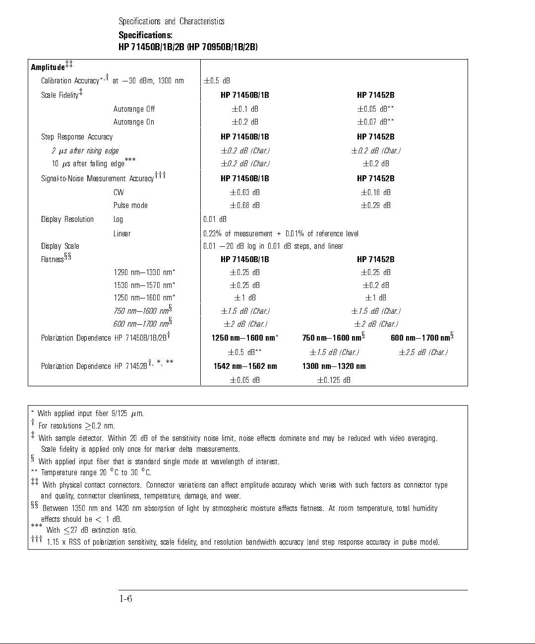
Amplitude
zz
Calibration Accuracy*
Scale Fidelity
z
,
y
at030 dBm, 1300 nm
Autorange O
Autorange On
Step Response Accuracy
2s after rising edge
10s after falling edge
Signal-to-Noise Measurement Accuracy
***
yyy
CW
Pulse mode
Display Resolution Log 0.01 dB
Linear 0.23% of
y Scale
Displa
x
x
Flatness
nm*
nm*
nm*
x
nm
x
nm
y
**
*,
,
y
olarization
P
olarization
P
Dependence
Dependence
nm|1330
1290
nm|1570
1530
nm|1600
1250
750 nm|1600
nm|1700
600
71450B/1B/2B
HP
71452B
HP
6
0.5 dB
HP 71450B/1B HP 71452B
6
0.1 dB
6
0.2 dB
HP 71450B/1B HP 71452B
6
0.2 dB (Char.)
6
0.2 dB (Char.)
6
HP 71450B/1B HP 71452B
6
0.63 dB
6
0.68 dB
level
reference
of
measurement +
dB log
0
20
0.01
71450B/1B HP
HP
dB
0.25
6
dB
0.25
6
dB
1
6
(Char
dB
6
1.5
(Char
dB
2
6
nm|1600
1250
dB**
0.5
6
nm|1562
1542
dB
0.05
6
0.01%
linear
and
steps,
dB
0.01
in
.)
6
.)
dB
0.125
nm
(Char
dB
nm
nm
nm|1600
750
*
1.5
6
nm|1320
1300
6
6
0.05 dB**
6
0.07 dB**
0.2 dB (Char.)
6
0.2 dB
6
0.18 dB
6
0.29 dB
71452B
0.25
6
dB
0.2
6
dB
1
6
(Char
dB
1.5
(Char
dB
2
6
x
.)
nm
dB
.)
.)
600
6
nm|1700
(Char
dB
2.5
nm
x
.)
* With applied input ber 9/125m.
y
For resolutions0.2 nm.
z
With sample detector. Within 20 dB of the sensitivity noise limit, noise eects dominate and may be reduced with video averaging.
Scale delity is applied only once for marker delta measurements.
x
With applied input ber that is standard single mode at wavelength of interest.
emperature
T
**
zz
xx
***
yyy
ysical contact
ph
With
connector
,
quality
and
Between 1350 nm and 1420 nm absorption of
eects should be
With27 dB extinction ratio
1.15 x RSS of polarization sensitivity
range
20
<
1dB
30
to
C
connectors.
cleanliness,
.
.
C
Connector
temperature
.
variations
damage
,
light b
, scale delity
can
and wear
,
aect
amplitude
.
accurac
with such
varies
which
y
y atmospheric moisture aects atness. At room temperature
, and resolution bandwidth accurac
y (and step response accurac
as
factors
, total humidity
y in pulse mode).
connector
1-6
type
Specications and Characteristics
Specications:
HP 71450B/1B/2B (HP 70950B/1B/2B)
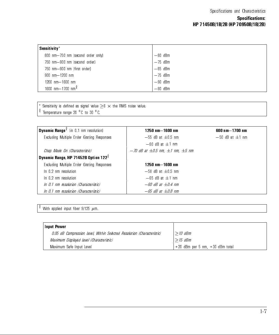
Sensitivity
*
600 nm|750 nm (second order only)
750 nm|900 nm (second order)
750 nm|900 nm (rst order)
900 nm|1200 nm
1200 nm|1600 nm
1600 nm|1700 nm
y
* Sensitivity is dened as signal value62the RMS noise value.
y
Temperature range 20Cto30C.
Dynamic
Excluding
Chop
Dynamic
Excluding
0.2 nm
In
0.2
In
0.1
In
0.1
In
y
Range
Multiple Order
On
Mode
HP
Range,
Multiple
resolution
nm resolution
resolution
nm
resolution
nm
(in
(Characteristic)
nm
0.1
Grating
71452B
Grating
Order
(Characteristic)
(Characteristic)
resolution)
Responses
Option
Responses
122
dB
70
0
y
1250
55 dB
0
60
0
6
at
1250
58 dB
0
65
0
60
0
65
0
0
60 dBm
0
75 dBm
0
65 dBm
0
75 dBm
0
90 dBm
0
80 dBm
nm|1600
at
at
dB
nm,
0.5
nm|1600
at
dB at
at
dB
at
dB
nm|1700 nm
nm
nm
0.5
6
nm
1
6
nm
5
6
nm,
1
6
600
0
nm
1
6
at
dB
50
nm
nm
0.5
6
nm
1
6
nm
0.4
6
nm
0.8
6
y
With
applied input
ber 9/125
m.
Input Power
0.05 dB Compression Level, Within Selected Resolution (Characteristic)
Maximum Displayed Level (Characteristic)
evel
L
Maximum Safe
Input
10 dBm
15 dBm
+20 dBm
per
total
dBm
+30
nm,
5
1-7

Specications and Characteristics
Specications:
HP 71450B/1B/2B (HP 70950B/1B/2B)
Input Return Loss with physical contact connectors
Fiber input size
: 9m
50m
62.5m
>
35 dB total (connector limited)
>
50 dB internal reections (Characteristic)
>
28 dB (Characteristic)
>
26 dB (Characteristic)
Sweep Time
(Characteristic)
Maximum Sweep Rate 40 nm / 50 ms
Maximum Sweep Rate in Zero Span 50s / trace point
Sweep Cycle Time
y
Sweep
ADC
rigger
T
c
ycle
Jitter
rigger Dela
T
y
includes
time
Accuracy
y Range
sweep
forward
(Characteristic)
50 nm span, auto zero o
nm span,
50
span,
nm
500
auto
span,
Full
sensitivity
dBm
80
0
sensitivity
dBm
90
0
plus overhead
time
auto zero
zero
auto
zero
between
on
30
,
30
,
on
on
nm
nm
sweeps.
span,
span,
auto
auto
zero
zero
<
180 ms
340 ms
<
ms
650
<
1s
<
on
on
s
0.5
6
ms
s|6.5
2
2s
<
35s
<
1-8
Additional Specications:
HP 71451B (HP 70951B)
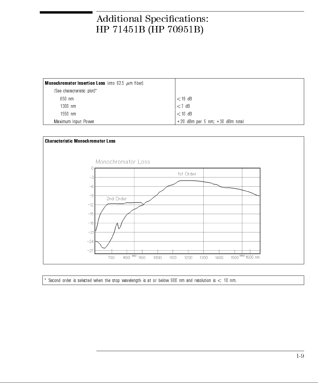
Monochromator Insertion Loss
(into 62.5m ber)
(See characteristic plot)*
850 nm
1300 nm
1550 nm
<
<
<
19 dB
7dB
10 dB
Maximum Input Power +20 dBm per 5 nm; +30 dBm total
Characteristic
Monochromator
Loss
*
Second
order
selected when
is
the
stop
wavelength
nm.
10
is
resolution
and
nm
900
below
or
at
is
<
1-9
Specications and Characteristics
Additional Specications:
HP 71451B (HP 70951B)
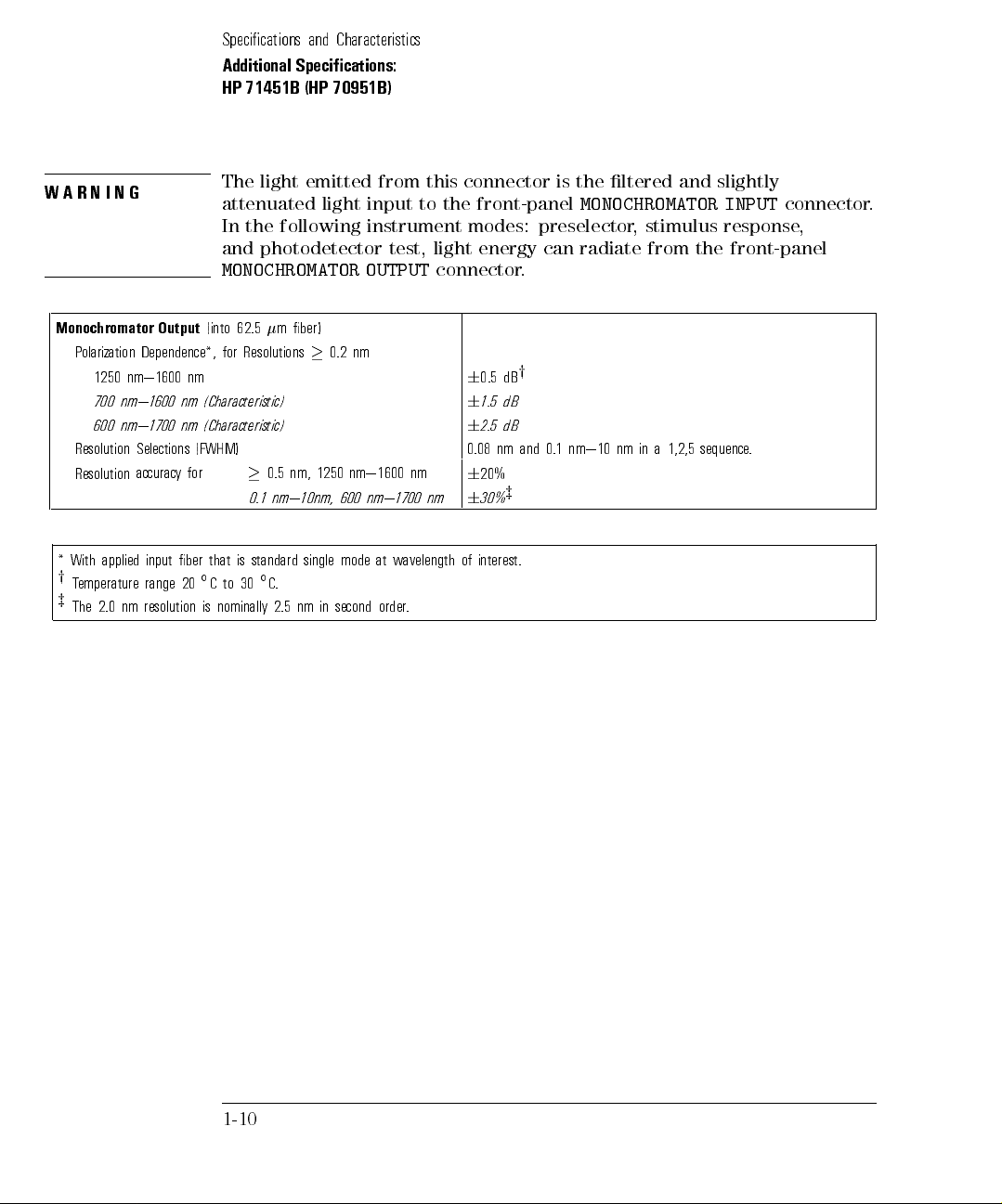
WARNING
The light emitted from this connector is the ltered and slightly
attenuated light input to the front-panel
In the following instrument modes: preselector, stimulus response,
and photodetector test, light energy can radiate from the front-panel
MONOCHROMATOR OUTPUT
Monochromator Output
(into 62.5m ber)
Polarization Dependence*, for Resolutions0.2 nm
1250 nm|1600 nm
700 nm|1600 nm (Characteristic)
(Characteristic)
nm
Selections (FWHM)
for
y
accurac
that
ber
input
20
range
resolution
to
C
nominally
is
0.1
standard
is
30
nm,
0.5
nm|10nm,
.
C
2.5
Resolution
Resolution
With
*
y
emperature
T
z
The
600 nm|1700
applied
nm
2.0
1250 nm|1600
600
mode at
single
second
in
nm
nm|1700
wavelength
.
order
connector.
nm
nm
6
6
6
0.08
6
6
of
0.5 dB
1.5 dB
dB
2.5
nm and
20%
z
30%
interest.
y
MONOCHROMATOR INPUT
1,2,5
a
in
0.1 nm|10
nm
sequence
connector.
.
1-10

Specications and Characteristics
Additional Specications:
HP 71451B (HP 70951B)
Photodetector Input
(in power meter mode)
Accuracyat030 dBm* (ref to 1300 nm)
20Cto30C
0Cto55C
6
6
Maximum Safe Power Level +20 dBm
1 dB Compression Level
Scale Fidelity (for+2 dBm inputs)
y
For any Measurement with Fixed Reference Level
Dierent
with
Displa
or
F
y
og
L
Multiple
Resolution
Measurements
Reference
evels
L
6
6
0.01
Linear 0.23% of
setting)
ower
P
Maximum
Sensitivity
Flatness
Range
(for
(up
Displa
x
2
to
y
dBm
50
ed
dB
el
v
Le
input)*
reference
y
an
in
(Characteristic)
level
0.35 dB
0.5 dB
+7 dBm
0.1 dB
dB
0.2
dB
1250
measurement
nm|1600 nm
dBm
10
dBm
95
0
dB
0.4
6
+
0.01%
reference
of
600
level
nm|1700
dBm
10
dBm
85
0
dB
2
6
nm
z
Transimpedance Input
Current Range 0to010 mA
Maximum Current
Maximum Voltage
Input Impedence
applied
With
*
y
To within 20 dB of the sensitivity noise limit.
z
Flatness for 1650 to
x
Sensitivity applies within 1 minute of last zeroing.
(Characteristic) 270
m.
9/125
ber
input
1700 nm applies for ambient temperature from 20
6
10 mA
6
10 V
Cto30C only
.
1-11

Specications: Optional Current Source
Current Output (Option 001)
Range 0to6200 mA (source or sink)
Resolution (Characteristic) 50A steps
Accuracy 2%650A
Clamp Voltage (nominal)
Noise Density at 1 kHz (Characteristic)
Stability Within 30 Minutes (Characteristic)
(Characteristic)
Mode
Range
Resolution
Cycle
Drift
Range
T
Pulse
Pulse
Pulse
Duty
emperature
6
2.7 V
<
4nA/pHz
<
100 ppm6500 nA
ppm
(100
<
to 6.5
s
10
ns
100
width/1
pulse
nA)/
500
6
ms
100%
to
s
C
1-12

Specications:
Optional Built-In White Light Source
Light Source Output (Option 002)
Wavelength* 900 nm to 1700 nm
Minimum Output Power Spectral Density (9/125m ber)
900 to 1600 nm
900 to 1600 nm (typical)
1600 to 1700 nm
0
67 dBm/nm (0.2 nW/nm)
0
64 dBm/nm (0.4 nW/nm)
0
70 dBm/nm (0.1 nW/nm)
Minimum Output Power Spectral Density (characteristic)
y
y
Output Stability (Characteristic)
mean time
Lifetime,
Lamp
Stimulus
Passive
(with
(with
Measurement
Dynamic
Measurement
Response
Optical-to-Optical
HP
HP
System
71450B/1B/2B
70950B/1B/2B
Range
(characteristic)
Range
Accurac
between
Specications
Devices
OSA)
OSA)
z
y
50/125m ber
62.5/125mber
(Characteristic)
(MTBF)
failures
RBW
nm
10
RB
nm
10
RB
10 nm
to
nm
0.5
0
50 dBm/nm (10 nW/nm)
0
46 dBm/nm (25 nW/nm)
6
0.02 dB over 10 minutes
hours
>
5000
nm
1600
to
1250
ber
m
9/125
dB
33
to
0
typical)
(36 dB
W
dB
36
W
W
RB
nm
10
dB
0.1
6
Optical-to-Electrical Devices
(with HP 71451A or HP 70951A OSA)
Minimum Responsivity (characteristic) Rshunt>1M 0.01 A/W 0.01 A/W
Accuracy (characteristic)
z
6
0.9 dB
to
900
62.5/125
30
to
0
40
to
0
(900|1000
dB
24
(1000|1600
36 dB
(1600|1700
dB
9
dB
0.2
6
6
0.9 dB
1700
or
dB
dB
nm
50/125
(1000|1600
nm)
nm)
nm)
ber
m
nm)
y
z
averaging. F
power
Includes
Does not include connector repeatability or eects of noise on measurement. Noise eects can be reduced with video
or multimode-ber measurements assume DUT does not
in full
numerical
aperture
.
ber
of
modify mode structure
.
nm.
850
below
Filtered
*
ltering or video
1-13

Specications: Optional Swept Polarization
Dependent Loss Kit
Swept PDL System Specications (HP 71451B Option 003) 1250 to 1600 nm
(with HP 71451B or HP 70951B OSA containing Option 002, Built-In White Light Source)
Accuracy*
O/O Devices (external photodetector) +0.1/00.05 dB
O/O Devices (internal photodetector) (characteristic) +0.2/00.1 dB
O/E Devices (characteristic) +0.075/00.025 dB
Polarizer Extinction Ratio
dB
30
to
0
Assumes
*
Measurement
polarization
Range
controller
(characteristic)
all
covers
desired
states
polarization.
of
loss.
dB
5
than
less
with
devices
or
F
1-14

General Specications
Inputs Outputs
Optical Output (HP 71451B or HP 70951B) 62.5m ber
Optical Input (HP 70950B/1B) Multimode ber, standard
Optical Input (HP 70952B) 9mber
Optical Connectors FC/PC standard; other interface adapters available
Rear-Panel Connectors SMB (electrical)
Dimensions
HP 71450B/1B/2B 222 mm high2425.4 mm wide2526 mm long
in)
20.7
2
in
16.75
2
in
(8.75
70950B/1B/2B
HP
Standard
4/8-width
module
Weight
71450B/1B/2B
HP
70950B/1B/2B
HP
Environmental Operational
Temperature 0Cto
Humidity
Shock and
Vibration
Tested
to
95%
<
MIL-T-28800D
28
8
+55
R.H.
class
kg
kg
(61.6
(17.6 lb)
C
par
5
.
3.7.4,
3.7.5.2
and
3.
Storage
40
0
Cto
Noncondensing
+71
C
lb)
EMI Conducted and radiated interference is in compliance with CISPR Pub 11 and MIL-STD 461C
part 7 CE03 (AF) and RE02.
Requirements
ower
P
71450B/1B/2B
HP
Hz
Hz|444
356
and
and
oltage
V
Maximum P
Frequenc
ower
y
87|132
174|264 V
47
,
AC
V
AC, 47 Hz|66 Hz
260 W maximum
Hz
Hz|66
(350 VA maximum)
1-15

Regulatory Information
The information on the following page applies to the HP 70950B/1B/2B optical
spectrum analyzer product.
1-16

Specications and Characteristics
Regulatory Information
1-17

Specications and Characteristics
Notice for Germany: Noise Declaration
LpA<70 dB
am Arbeitsplatz (operator position)
normaler Betrieb (normal operation)
nach DIN 45635 T. 19 (per ISO 7779)
1-18

2
Menu Maps

Menu Maps
The menu maps that are in this chapter graphically represent the softkey
menus that are located under the
4
MENU
5
key. Maps for each left-side softkey
are shown in alphabetical order. Menu maps contain the following features:
2-2

Menu Maps
Contents
Amptd Menu
BW, Swp Menu
Marker Menu
Misc Menu
State Menu
::::::: ::::::: :::::: ::::::::: :::::::::::::: :::::: ::::::: ::::::
::::::: :::::: ::::::: ::::::::: ::::::::::::: ::::::: ::::::: ::::
Traces Menu
Waveln Menu
4
5
Menu's DFB Advanced Measurement Program
USER
4
5
Menu's FP Advanced Measurement Program
USER
4
5
Menu's LED Advanced Measurement Program
USER
4
5
Menu's Optional PDL Advanced Measurement Program
USER
::::: ::::::: ::::::: ::::::::: ::::::::::::: ::::::: :::::: ::::::
::::: ::::::: ::::::: ::::::::: ::::::::::::: ::::::: :::::: ::::
:::::: ::::::: :::::: ::::::::: :::::::::::::: :::::: ::::::: ::::
:::::: ::::::: :::::: ::::::::: ::::::::::::: ::::::: ::::::: ::::
::::::::::::::::::::::::::::::::::::::::::::::::::::::::::
::::::::::::::::::
::::::: :::::: :::::::
::::::: ::::::: ::::
:::::::::
2-4
2-5
2-6
2-8
2-10
2-12
2-13
2-14
2-15
2-16
2-17
2-3

Amptd Menu
Menu Maps
2-4

BW, Swp
Menu
Menu Maps
BW, Swp Menu
2-5

Marker Menu
Menu Maps
Marker Menu
2-6

This page is intentionally left blank.
Menu Maps
Marker Menu
2-7

Misc Menu
Menu Maps
Misc Menu
2-8

Misc menu
(cont'd)
Menu Maps
Misc Menu
2-9

State Menu
Menu Maps
State Menu
2-10

State menu
(cont'd)
Menu Maps
State Menu
2-11

Traces Menu
Menu Maps
Traces Menu
2-12

Waveln Menu
Menu Maps
Waveln Menu
2-13

4
5
USER
DFB
Advanced
Measurement
Program
Menu's
Menu Maps
4
5
Menu's DFB Advanced Measurement Program
USER
2-14

4
5
USER
FP Advanced
Measurement
Program
Menu's
4
5
Menu's FP Advanced Measurement Program
USER
Menu Maps
2-15

4
5
USER
LED
Advanced
Measurement
Program
Menu's
Menu Maps
4
5
Menu's Optional PDL Advanced measurement Program
USER
2-16

Menu Maps
4
5
USER
Menu's
PDL
Advanced
Measurement
Program
This program is available on HP 71451B (HP 70951B) instruments as Option
003.
2-17

Menu Maps

3
Dictionary
Reference

Dictionary Reference
This chapter is a dictionary reference of front and rear-panel connectors,
front-panel keys, and softkeys. With the exception of a few front-panel keys,
softkeys control all instrument functions. Refer to the display's operating
manual for information on softkeys located under the
4
DISPLAY
5
key.
This chapter is designed for quick access of information. For example,during
operation you may nd a softkey or hardkey whose function is unfamiliar
to you. Note the key name, nd the key in this chapter, and read the
a
denition.
brief
softkey.
functions.
with
begin
E
OT
N
Throughout
modules
In
This occurs
Make sure
a symbol
chapter
this
congured
with
several
places
whenever two
you have
are listed
71450B/1B/2B
HP
,
70004A
HP
the
you
sofkeys have
found the
front
the
at
refers
.
y
displa
nd
will
applicable
the
to
multiple
the
of
70950B/1B/2B
HP
same
the
denition.
chapter
denitions
name
.
optical
for
but
eys
K
spectrum
dierent
that
analyzer
3-2

Alphabetical Listing
45
Use the
485
The
sweeptime
pressing
45
(backspace) key for the following uses:
backspacing the
displaying previous
4
5
9
increase
keys
step
the
is
4
decreases
5
9
415
custom-keypad
This
Delta
markers
allow
cursor while
softkey menus
decrease
or
active
parameter
the
activates
key
to
you
sweep
entering
.
active
pressing
,
.
time
NNNNNNNNNNNNNNNNNNN
N
the
Marker
compare two
text.
parameter
4
increases
5
8
menu's
values
trace
values
NNNNNNNNNNNNNNNN
N
DELTA
both
in
.F
the
example
or
sweep
function.
trace
,
time;
domains
if
.
3-3

Dictionary Reference
Alphabetical Listing
See Also
Path
ey
K
DELTA
in this chapter.
1/T
Softkey that congures marker readouts to show marker position as the
inverse of the marker sweep-time position.
NNNNNNNNNNN
sweep
determine
to
single
the
of
of
cycle
periodic
Pressing
the
at
time
frequency
signal.
Then,
the
of
1/T
marker
periodic
a
selecting
softkey
zero
In
.
N
selects
span,
signal.
N
N
N
N
N
N
N
N
N
N
1/T
marker
this
delta
Use
readouts
readouts
function
markers
shows
can
frequency
the
as
to
the
be
mark
inverse
used
a
signal.
N
N
N
N
N
N
N
N
N
N
N
N
N
N
N
N
N
N
N
N
N
Press
Marker
3-DIMEN
N
N
NN
N
N
N
N
N
N
N
,
MORE
On
N
N
N
N
N
N
N
O
N
N
N
N
N
NN
N
N
N
N
N
N
N
N
N
of
1
N
N
N
,
4
MORE
NN
N
N
N
N
N
N
N
N
N
N
N
N
N
N
N
2
N
N
of
N
N
N
N
N
N
N
N
N
N
N
N
N
4
N
N
N
N
N
N
,
marker
N
N
N
N
N
N
N
N
N
N
N
N
N
N
N
N
N
N
N
NN
readout
N
N
N
N
N
N
N
N
N
N
N
N
N
N
N
N
N
,
N
N
N
N
1/T
the
the
of
N
N
N
N
N
N
N
.
Softkey that
views the
3-dimensional display
.
Three-dimensional views provide a graphic measurement history. They oer
a view of the input spectra over time. The optical spectrum analyzer displays
successive traces with each trace slightly oset. This gives a 3-dimensional
\look" with the third dimension showing changes in signal response with
time. New traces are placed at the front of the 3-dimensional view as older
.
position.
may
appear
sluggish.
This
sweeps
With
is
Use the
response to front-panel controls
with the
progressively
3-dimensional
due to the additional time required to obtain and display the trace data.
fastest sweeps possible to increase the optical spectrum analyzer's
NNNNNNNNNNNNNNNNNNNNNNNNN
3-DIMEN On Off
move to
displays,
NNNNNNNNNNNNNNNNNNN
the
front-panel
control
. Decreasing the number of three-D levels
softkey also helps
background
last
3-4

3-Dimensional Default Values
Default Value Limit
Dictionary Reference
Alphabetical Listing
Path
ey
K
Related
Command
Programming
Traces
Horizontal Oset
Vertical Oset
16 limited by available internal memory (100 maximum)
4
10
6
200
6
200
Normally, 16 traces are displayed to provide the 3-dimensional view.
However, you can increase or decrease the number of traces. The number of
traces that can be displayed is limited by the amount of available internal
increase
you
display
N
N
N
N
N
N
N
N
N
that
the traces
large as
.
N
N
N
N
N
N
N
N
NN
N
N
N
N
N
N
N
N
of
3
to
helps
be
can
200
N
N
N
N
N
N
N
,
4
memory
internal
Changing
optimize
entered,
N
N
N
N
Press
Traces
N
N
N
N
N
N
N
N
N
N
N
N
N
N
N
N
N
N
N
3-DIMEN
. Viewing
memory
vertical
the
3-dimensional
the
values
NN
N
N
N
N
N
N
N
N
N
N
N
N
N
N
,
N
N
N
N
N
N
N
N
N
N
N
N
NN
N
N
N
N
N
Off
On
large
deleting les
by
or
30
of
N
N
N
N
N
N
N
N
N
N
N
N
N
N
N
MORE
N
N
N
N
N
N
.
numbers
horizontal
and
less are
N
N
N
N
N
N
N
NN
N
N
N
of
1
eect.
N
N
N
N
N
N
N
N
,
4
traces
of
.
osets between
Although
normal for
N
NN
N
N
N
N
N
N
N
N
N
N
N
N
N
N
N
N
N
N
MORE
2
N
N
of
may
N
N
N
proper
N
N
N
N
require
osets as
N
N
N
N
N
N
,
4
MORE
THREED
A
A
0
B
Softkey that subtracts Trace B from Trace A point by point, then stores the
results
If
sweep.
a reference level adjustment.
0
places trace A at
in
trace
A
is in
clear-write
mode
function
this
Results of the subtraction are referenced to 0 dB
, if the reference level is set at
40 dBm, Trace A is at
0
5dB
For example
0
50 dBm, and Trace B is at
. Because this is o screen,
continuous
is
and
. This often requires
NNNNNNNNN
0
55 dBm,
A
the reference level needs
occurs
NNNNNNNNNNNNNNNNNNNNNN
every
A-B
A.
Trace
to be adjusted.
3-5

Dictionary Reference
Alphabetical Listing
This process occurs with each sweep. Placing the optical spectrum analyzer
in single sweep mode allows you to view the results of the trace math. Trace
math is mainly used to normalize the display during stimulus-response
measurements.
Key Path
Related Programming
Command
Path
ey
K
Programming
Related
Command
Press
AMB
A
Softkey
trace
in
results
The
placed
is
A
during
Press
APB
NNNNNNNNNNNNNNNNNNNN
Traces
NNNNNNNNNNNNNNNNNNNNNNNNNNNNNNNNNNN
,
MORE 1 of 4
A+B
trace
adds
that
A.
function
this
of
mode
view
in
stimulus-response
N
N
N
N
N
N
NN
Traces
N
N
N
N
N
N
N
N
N
N
N
N
N
,
N
N
N
N
N
N
NN
MORE
N
N
N
N
and
A
often
Trace
.
measurements
N
N
N
N
N
NN
NN
N
N
N
N
N
N
N
N
N
N
N
of 4
1
NNNNNNNNNNNNNNNNNNNNNNNNNNNNNNNNNNNNNNNNN
,
trace logmath
point
B
trace
mainly
is
a
requires
math
.
N
N
N
N
N
NN
,
oneshot
N
N
N
N
NN
N
N
N
N
N
N
N
N
N
N
N
N
N
N
N
math
,
point, then
by
reference
used
N
N
N
N
N
N
N
N
N
N
NN
,
NNNNNNNNNNNNNNNNNNNNNNNNNNNNNNN
A
A-B
stores the
level
to normalize
N
N
N
N
N
N
NN
A
N
N
N
N
N
N
N
N
N
N
N
N
N
N
N
N
A+B
.
adjustment.
the
N
.
results
Trace
display
A
Softkey
If trace
sweep.
3-6
(A0B)0C
that
subtracts
both
trace
trace C
and
B
from
A.
trace
A is in clear-write mode this function is continuous and occurs every

Dictionary Reference
Alphabetical Listing
Key Path
Related Programming
Command
Path
ey
K
Related
Command
Programming
NNNNNNNNNNNNNNNNNNNN
Press
Traces
AMBMC
A
(A
Softkey
display
The
addition,
trace
Press
AMBMCPL
that
line
trace
taken.
is
N
N
N
N
N
N
N
Traces
0B)0
subtracts
.
math
initial
an
N
N
NN
N
N
N
N
N
N
NNNNNNNNNNNNNNNNNNNNNNNNNNNNNNNNNNN
,
MORE 1 of 4
C+DL
both
performed
is
application
N
N
N
N
,
N
N
MORE
N
N
N
N
NN
N
N
N
N
N
N
N
N
N
N
1
NNNNNNNNNNNNNNNNNNNNNNNNNNNNNNNNNNNNNNNNN
,
trace logmath
trace
and
B
trace
point
trace
each
on
function
the
of
N
N
N
N
N
N
N
N
N
N
N
N
N
N
N
N
4
of
N
N
N
,
trace
N
N
N
N
N
N
N
N
N
N
N
N
N
N
N
N
N
NN
N
logmath
N
N
N
N
N
N
NNNNNNNNNNNNNNNNNNNNNNNNNNNNNNNNNNNNN
,
A
from
C
as the
performed
is
N
NN
N
N
N
N
N
N
N
N
N
N
N
,
A
trace
N
N
N
N
N
(A-B)-C
A,
trace is
before
N
N
N
N
N
N
NN
N
N
N
N
N
N
(A-B)-C+DL
then
formed. In
N
N
N
N
N
N
N
N
N
N
N
N
N
N
.
adds
the
NN
N
N
N
N
N
N
N
N
next
N
N
N
N
.
the
B+DL
0
A
A
Softkey that subtracts trace B from trace A point by point, adds the value
of the display line, and then stores the results in trace A. Use this function
when placing the results of trace subtraction at a specic location.
N
N
N
N
N
N
N
N
N
NN
on the
turn
o
T
then
and
knob to position the display line
result of the trace subtraction to be located.
If trace A
sweep. This function is eective when wanting to place the results of trace
subtraction at a specic location. The process is continuous and occurs with
display
NN
N
N
N
N
N
N
N
N
N
N
N
NN
N
LIN
DSP
is in clear-write mode this function is continuous and occurs every
line
N
N
NN
N
N
N
N
N
N
N
N
N
N
N
NN
N
N
N
N
N
N
N
N
N
N
On
Off
Traces
N
that
so
. Place the display line where you desire the
N
NN
On
N
N
N
N
N
N
N
N
press
,
N
N
N
N
N
N
N
,
MORE
underlined.
is
N
N
N
N
N
N
N
NN
N
N
N
N
N
N
N
N
N
N
N
N
N
N
N
N
N
N
N
NN
N
N
N
N
of
1
4
Use
,
the
N
N
N
MORE
N
N
N
N
N
N
NN
N
N
N
N
N
N
N
N
2
front-panel
N
N
N
N
N
N
N
N
N
NN
N
N
N
N
N
4
of
3-7
,

Dictionary Reference
Alphabetical Listing
each sweep. Placing the optical spectrum analyzer in single sweep mode
allows you to view the results of the trace math. Trace math is mainly used
to normalize the display during stimulus-response measurements.
Key Path
See Also
Related Programming
Command
N
NNNNNNNNNNNNNNNNNNN
Press
Traces
DSP LIN On O
N
NNNNNNNNNNNNNNNNNNNNNNNNNNNNNNNNNN
,
MORE 1 of 4
in this chapter.
N
NNNNNNNNNNNNNNNNNNNNNNNNNNNNNNNNNNNNNNNN
,
trace logmath
N
NNNNNNNNNNNNNNNNNNNNNNNNNNNNNNNNN
,
A
A-B+DL
.
AMBPL
C
0
A
A
requires
set
N
N
N
NN
NN
N
N
A
the
every
at
N
N
N
N
N
N
N
N
-
needs
N
C
Softkey
results
If
sweep
a
0
places
to
in
trace
.
reference
dBm,
40
trace A
be adjusted.
that
Trace
in
is
A
Results
level
trace
subtracts
A.
clear-write
the
of
adjustment.
is
A
5
0
at
C
Trace
mode
subtraction
dBm,
55
0
at
Because
.
dB
from
or
F
this
Trace
function
referenced
are
example
trace
and
is
this
,
o
point
A
is
the
if
is
C
screen,
point,
by
continuous
.
dB
0
to
reference
dBm,
0
50
at
reference
the
and
This
level
then
often
N
N
N
N
A
stores
occurs
is
N
N
N
N
N
level
Placing the optical spectrum analyzer in single sweep mode allows you to
view the results of the trace math. Trace math is mainly used to normalize
the display during stimulus-response measurements.
N
N
N
N
Key Path
Related
Command
Programming
Press
AMC
3-8
NNNNNNNNNNNNNNNNNNNN
Traces
NNNNNNNNNNNNNNNNNNNNNNNNNNNNNNNNNNN
,
MORE 1 of 4
NNNNNNNNNNNNNNNNNNNNNNNNNNNNNNNNNNNNNNNNN
,
trace logmath
NNNNNNNNNNNNNNNNNNNNNNNNNNNNNNN
,
A
A-C
.

Dictionary Reference
Alphabetical Listing
A
A
0
C+DL
Softkey that subtracts trace C from trace A point by point, adds the value of
the display line, and then stores the results in trace A.
This function is eective when wanting to place the results of trace
subtraction at a specic location. The process is continuous and occurs with
each sweep. Placing the optical spectrum analyzer in single sweep mode
allows you to view the results of the trace math. Trace math is mainly used
to normalize the display during stimulus-response measurements.
N
N
N
N
N
N
N
N
N
N
NN
NN
NN
N
N
N
N
N
N
N
N
N
T
then
and
position
to
knob
the
of
result
N
N
N
N
N
N
N
N
N
Path
ey
K
Press
Traces
N
NN
N
DSP
NN
N
N
N
N
N
N
N
trace
N
N
N
N
N
N
N
N
N
N
N
N
LIN On
N
N
N
,
MORE
display
the
on
turn
o
line
N
N
N
N
N
NN
NN
NN
NN
N
N
N
N
display
the
subtraction
N
N
N
N
N
NN
N
N
N
N
N
N
N
N
N
N
N
1
N
N
N
N
N
Off
N
N
N
N
of
N
that
so
.
line
to
N
N
N
N
N
N
N
N
N
N
N
N
4
N
N
,
trace
Place
be
N
N
N
N
N
N
N
N
N
N
N
N
N
NN
N
On
the
located.
N
N
N
N
N
N
NN
N
N
logmath
Traces
N
N
N
N
N
N
N
N
N
N
press
,
N
N
N
N
N
N
N
N
N
,
MORE
is underlined.
display
N
N
N
N
N
N
N
N
N
N
N
N
N
N
N
N
N
N
N
N
N
N
NN
NN
NN
N
N
N
N
N
of
1
line
N
N
NN
N
N
N
N
N
N
N
N
,
A
,
4
Use the
where
N
N
N
N
N
NN
N
N
N
N
A-C+DL
N
N
N
MORE
N
N
N
N
N
NN
NN
NN
N
N
N
N
N
N
N
N
N
N
N
2
front-panel
desire
you
N
N
N
N
N
N
N
N
N
N
.
N
N
N
of
N
N
N
N
N
N
N
N
N
N
N
N
,
4
the
Also
See
Related Programming
Command
B
this
.
.
function
in
linear
display
allows
mode.
It
. If a division by
performed
ratio
3-9
chapter
this
in
O
On
LIN
DSP
AMCPL
A
A*DL/(A+B)
Softkey that multiplies trace A by the display line and then divides the result
and
traces
of
sum
the
by
proper
or
F
measurements to be made as a sweep is taken. If trace B has points near the
bottom of the screen, overow or poor precision can occur
zero is attempted, a division by the smallest representable value is
instead.
operation,
A
use

Dictionary Reference
Alphabetical Listing
To ensure that correct data is displayed, be sure that a sweep is taken before
using this function.
Key Path
Related Programming
Command
Path
ey
K
NNNNNNNNNNNNNNNNNNNN
Press
Traces
ADAPBTL
A
Softkey
by
F
A*DL/(A+B+C)
that
of
sum
the
or
proper
operation,
measurements
the
bottom
zero
of
attempted,
is
instead.
ensure
o
T
using
Press
that
function.
this
N
N
N
N
N
N
N
N
NN
NN
NN
Traces
N
N
NNNNNNNNNNNNNNNNNNNNNNNNNNNNNNNNNNN
,
MORE 1 of 4
multiplies
traces
A,
use
made
be
to
screen,
overow
division
a
correct
N
N
N
N
,
N
N
NN
NN
NN
MORE
N
N
N
N
N
N
N
N
trace
B
data
N
N
N
N
N
N
1
and
,
this
as
is
NN
NN
NN
NN
N
of 4
NNNNNNNNNNNNNNNNNNNNNNNNNNNNNNNNNNNNNNNNN
,
trace linmath
display
the
by
A
C.
function in
sweep is
a
or
the smallest
by
displayed,
N
N
N
N
NN
NN
NN
,
trace
taken.
poor precision
be
N
N
N
N
N
N
N
N
N
N
N
N
N
N
N
N
linmath
,
line
display
linear
If
can
representable
that
sure
N
N
N
N
N
N
N
N
N
N
NN
NN
NN
NN
N
,
NNNNNNNNNNNNNNNNNNNNNNNNNNNNNNNNNNNNNNNNNNNNNN
A
A*DL/(A+B)
divides
then
and
allows
It
.
mode
points
has
B
trace
division
a
If
.
occur
is
value
taken before
is
N
N
N
N
N
N
N
NN
NN
NN
NN
N
N
N
N
N
N
N
N
N
N
N
A*DL/(A+B+C)
NN
A
NN
a
N
N
N
NN
sweep
N
N
N
.
result
the
ratio
the
near
by
performed
NN
NN
N
N
N
N
N
N
N
N
N
N
.
Related Programming
Command
ADAPBPCTL
A
A*DL/B
Softkey that multiplies trace A by the display line value
result by trace B
.
3-10
, then divides the

Dictionary Reference
Alphabetical Listing
For proper operation, use this function in linear display mode. It allows ratio
measurements to be made as a sweep is taken. If trace B has points near the
bottom of the screen, overow or poor precision can occur. If a division by
zero is attempted, a division by the smallest representable value is performed
instead.
To ensure that correct data is displayed, be sure that a sweep is taken before
using this function.
Key Path
See Also
Related
Command
Key Path
Programming
Press
A
NNNNNNNNNNNNNNNNNNNN
Traces
A*DL/C
NNNNNNNNNNNNNNNNNNNNNNNNNNNNNNNNNNN
,
MORE 1 of 4
chapter
this
in
NNNNNNNNNNNNNNNNNNNNNNNNNNNNNNNNNNNNNNNNN
,
trace linmath
.
NNNNNNNNNNNNNNNNNNNNNNNNNNNNNNNNNN
,
A
A*DL/B
.
ADBTL
A*DL/C
A
can
the
Chas
occur
.
value
Softkey
by
result
proper
or
F
points
a
near the
division by
multiplies
that
trace
operation,
C.
bottom
zero
trace
use
of
attempted,
is
this
the
by
A
function
screen,
a
display
the
in
overow
division
linear
the
by
line
display
or
,
value
precision
poor
smallest
divides
then
If trace
.
mode
representable
is performed instead. To ensure that correct data is displayed, be sure that a
sweep is taken before using this function.
Press
NNNNNNNNNNNNNNNNNNNN
Traces
NNNNNNNNNNNNNNNNNNNNNNNNNNNNNNNNNNN
,
MORE 1 of 4
NNNNNNNNNNNNNNNNNNNNNNNNNNNNNNNNNNNNNNNNN
,
trace linmath
NNNNNNNNNNNNNNNNNNNNNNNNNNNNNNNNNNNNN
,
A
A*DL/C
.
If
Also
See
Related Programming
Command
A*DL/B
A
ADCTL
in
this
chapter
.
3-11

Path
ey
K
Related
Command
Programming
Dictionary Reference
Alphabetical Listing
A
DL*(A+B)/C
Softkey that multiplies the sum of traces A and B by the display line.Then,
this result is divided by trace C. The nal results are stored in trace A.
For proper operation, use this function in linear display mode. If trace A is in
clear-write mode, the function is continuous and occurs every sweep. Only
one trace math operation may be active at any given time. If trace C has
points near the bottom of the screen, overow or poor precision can occur.If
a division by zero is attempted, a division by the smallest representable value
performed instead.
is
sweep
Press
is taken
NN
N
N
N
N
N
N
N
N
N
N
N
N
Traces
N
N
N
N
NN
,
ensure
To
before using
N
N
N
N
N
N
N
N
NN
NN
N
N
N
N
N
N
N
N
N
N
N
N
MORE
of
1
that
this function.
N
N
N
N
N
N
N
N
N
N
N
4
N
N
N
,
trace
N
N
N
N
N
correct
NN
NN
N
N
N
N
N
N
N
N
N
N
N
N
N
N
N
N
N
N
N
linmath
data
N
N
N
N
N
is
NN
NN
N
,
displayed,
NN
N
N
N
N
N
N
N
N
N
N
N
N
A
be
NN
N
N
N
N
N
N
N
N
N
N
N
N
N
N
N
N
N
N
N
N
N
NN
DL*(A+B)/C
N
N
N
N
N
NN
.
a
that
sure
APBDCTL
Path
ey
K
Related Programming
Command
A METER
Softkey that
On O
displays the
power level
of
the
trace
point
currently
being
measured at the optical spectrum analyzer's input.
The displayed value shows the amplitude level for the last acquired trace
point. This feature is automatically turned on whenever HP 71451B optical
spectrum analyzers are in the Power Meter instrument mode.
Press
N
N
N
N
N
N
NN
N
N
N
Amptd
N
N
N
NN
N
N
N
N
N
N
N
N
NN
N
N
N
N
NN
N
N
N
,
MORE
N
N
N
NN
N
N
N
N
N
N
N
N
N
N
of
1
N
N
N
,
4
MORE
N
N
NN
N
N
N
N
N
N
N
N
N
N
NN
2
N
N
N
N
N
NN
N
N
N
N
N
N
N
N
N
4
of
,
NN
N
N
N
A
N
N
N
N
N
N
N
METER
N
N
N
N
N
N
N
N
N
N
N
NN
N
N
N
On
N
N
NN
N
N
N
N
N
N
N
N
N
N
NN
Off
.
N
N
AMETER
3-12

Dictionary Reference
Alphabetical Listing
A UNITS AutoMan
Softkey that selects the display units for the amplitude scale.
Normally, the optical spectrum analyzer automatically selects the amplitude
units according to whether the scale is logarithmic (dBm) or linear (watts). In
this condition,
key to manually select the display units,
NNNNNNNNNNNNNN
Auto
in the softkey label is underlined. When you use this
NNNNNNNNNNN
Man
is underlined. You can select
either units in dB or Watts.
Path
Key
Related Programming
Command
ey Path
K
Related Programming
Command
Press
UNITS
A
XCH
A
Softkey
Press
AXB
XCH C
A
N
N
N
N
N
N
N
N
N
N
N
N
N
Amptd
B
that
N
N
N
N
N
N
N
N
N
N
N
N
N
Traces
N
N
N
N
N
N
N
N
N
N
N
N
N
N
N
,
units menu
exchanges
NN
NN
N
N
N
N
,
N
N
N
N
N
N
N
MORE
N
N
N
N
N
N
NN
NN
N
N
N
N
NN
N
N
N
N
N
1of
NN
the
NN
NN
N
NN
NN
N
N
N
N
N
N
N
N
N
,
A UNITS
contents
N
N
N
N
N
N
N
N
N
N
N
,
4
N
N
N
N
N
N
N
N
N
N
N
N
N
N
of
N
N
N
N
N
N
N
N
N
N
N
N
oneshot
N
N
N
NN
NN
NN
NN
AutoMan
trace
NN
NN
NN
NN
N
N
N
N
N
N
N
N
N
N
N
N
N
N
N
N
N
math
NN
NN
N
N
N
N
N
N
N
Aand
N
N
N
N
N
N
N
N
,
.
trace B
N
N
N
N
N
N
N
A
NN
N
N
N
N
N
N
N
N
N
XCH B
registers
N
NN
NN
.
.
Softkey that exchanges the contents of the trace B and trace C registers
.
3-13

Dictionary Reference
Alphabetical Listing
Key Path
Related Programming
Command
NNNNNNNNNNNNNNNNNNNN
Press
Traces
AXC
ACT
Front-panel
active
The
displayed.
being
system.
the
CTIVE
A
Softkey
that
NNNNNNNNNNNNNNNNNNNNNNNNNNNNNNNNNNN
,
MORE 1 of 4
indicator
indicator
CT)
(A
The
MARKER
selects
the
light.
lights
indicator
active
NNNNNNNNNNNNNNNNNNNNNNNNNNNNNNNNNNNNNN
,
oneshot math
whenever
operative
only
is
marker
.
NNNNNNNNNNNNNNNNNNNNNNN
,
AXCH C
optical spectrum
the
when
.
there is
analyzer is
a display
in
Key Path
ve markers
Up to
displayed, use
or
F
changes
then
.
NNNNNNNNNNNNNNNNN
ENTER
NNNNNNNNNNNNNNNNNNNN
Press
Marker
3-14
can be
this softkey
example
,
.
NNNNNNNNNNNNNNNNNNNNNNNNNNNNNNNNNNN
,
MORE 1 of 4
simultaneously
to select
marker
select
to
NNNNNNNNNNNNNNNNNNNNNNNNNNNNNNNNNNN
,
MORE 2 of 4
which
2,
displayed.
marker
press
is
N
N
N
N
N
N
ACTIVE
NNNNNNNNNNNNNNNNNNNNNNNNNNNNNNNNNNNNNNNNN
,
ACTIVE MARKER
active
N
N
N
N
N
N
multiple
If
N
N
NN
NN
NN
NN
N
MARKER
for
N
N
N
N
N
N
N
N
N
N
N
markers
front-panel
N
NN
N
N
N
N
4
,
and
,
5
2
.
are

Dictionary Reference
Alphabetical Listing
adc sync
Softkey that presents a menu for synchronizing an external light source,
that has pulse modulation capability, with the optical spectrum analyzer's
analog-to-digital converter.
This menu controls a TTL signal available at the rear-panel
ADC SYNC OUT
connector. (The connector has a 50 output impedance.) You can adjust the
signal's pulse width and duty cycle. Pulse width determines the time that the
light source is turned on. Duty cycle determines the ratio of \on" and \o"
percentage:
a
as
e
cl
cy
OUT
must
cycle is
may increase
analyzer
selecting
aects
the
aects
analyzer
pul
=
pul
output
be greater
than
less
to perform
pulse width
average
power
the
idth
w
se
per
se
be
to
100%,
slightly
iod
active
than
(
100
nm.
0
this
during
,
various
and
power
dissipated
produced
measurements
)
optical
the
(When
output
is
measurements
internal
cycle
duty
by
light
the
by
performed
are
spectrum
span
the
disabled.)
.
tasks
values:
light
the
source
near
analyzer's
set
is
allow
to
Consider
source.
during its
the
nm
0
to
the
the
\on"
trailing
the
is entered
ADC
time and
or
F
wavelength
duty
the
and
pulse
The
optical
spectrum
following
cycle
Duty
width
Pulse
.
time
Optical
duty
SYNC
span
period
when
spectrum
edge of the pulse.
Pulse widths can range from 1sto6.5ms. However, not all combinations
of pulse widths and duty cycles are available. The optical spectrum analyzer
limits and adjusts these parameters as needed to maintain the following
conditions:
.
s
200
least
at
for
o
be
must
Pulse
Sweep time cannot be longer in seconds than the number of trace
measurement points
For pulsed measurements
.
, sweep times cannot be longer than 1 second per
trace point. This is 800 seconds for the default value 800 trace points
.The
3-15

Dictionary Reference
Alphabetical Listing
following equation shows how sweep time is approximately related to trace
length, pulse width, and duty cycle:
sweep time
'(trace length
(
pulse width)(100
)
duty cycle
)
UNCAL
indicates narrow pulses
Although the pulse widths can be set as narrow as 1s, if the width is too narrow for the optical
spectrum analyzer's circuitry, the displayed response may not faithfully represent the input light. To
indicate this condition, the
video-bandwidth
The
still
while
used
be
dependent
bandwidth
determined
is
is
by
dB-per-division
minimum
The
.)
mode
UNCAL
setting
maintaining
on
reference-level
logarithmic
setting
in
pulse
message is displayed.
minimum
the
limits
amplitude
an
screen
of
top
the
position,
mode
widths
available
pulse
calibrated
amplitude
reference
the
and
shown
are
width
display
level
and
level,
reference
the
in
can
that
(Video
.
which
the
level
following
in
Video Bandwidth Minimum Recommended
Width
Pulse
700
600
kHz
kHz
s
1
s
1
60 kHz 10s
20 kHz 30s
200 Hz 3ms
linear
table
.
Path
ey
K
See Also
N
N
N
N
NN
N
N
N
N
Press
State
OSA PULSE
3-16
N
N
N
N
N
N
N
,
N
NN
N
N
N
N
MORE
N
N
N
N
N
N
N
N
in this chapter
N
N
N
N
NN
N
N
N
N
N
N
N
N
N
N
N
NN
N
of
1
4
N
N
N
,
instr
N
NN
N
N
N
N
N
N
N
N
N
N
NN
N
NN
N
N
N
N
N
N
N
N
N
N
modes
N
N
N
N
,
N
N
N
N
OSA
N
N
N
N
N
N
N
NN
N
N
N
N
N
N
NN
N
N
N
PULSE
N
N
N
N
N
,
N
N
N
N
adc
N
N
N
N
NN
N
N
N
N
N
sync
N
N
N
N
N
N
N
N
NN
N
.
.

Dictionary Reference
Alphabetical Listing
ADC SYNC OUT
A rear-panel output connector.
A TTL/CMOS compatible output which allows the user to synchronize an
event external to the instrument (such as DUT power) to the instrument data
acquisition. This is useful for laser chip testing where power dissipation
prohibits continuous operation. There is one output pulse for each horizontal
point (bucket) on the display variable from 1s to 6.5 ms in 100 ns steps.
The connector is a standard SMB coaxial male jack with its outer conductor
50
a
connected directly
output impedance
to the
.
rear
panel
(earth
ground).
The
connector
has
trigger
adc
analyzer
source
is
pulsed
a
softkeys
that
Softkey
to
The
converter
connected
presents
light
in
(ADC).
the
to
a
.
source
menu
the
TTL-compatible
The
rear-panel
menu
select
synchronizing
for
the
TRIG
EXT
type
trigger
IN
the optical
triggering
of
signal
connector
from
.
for
spectrum
analog-to-digital
the
light
the
Softkey Type of Triggering
ADCTRIG FREE External triggering is ignored. The ADC is triggered
during sweeps by the optical spectrum analyzer's
internal clock.
external
the
edge
of
of
the
external
ADCTRIG
ADCTRIG
POSEDGE
NEGEDGE
ADC
trigger
ADC
triggered
is
signal.
is triggered
by
by
rising edge
the
falling
the
trigger signal.
ADCTRIG A
C ADC is
edges of the external trigger signal.
alternately triggered by rising and lling
The amplitudes
measured on opposite edges are subtracted and
3-17

Dictionary Reference
Alphabetical Listing
the absolute value of the result becomes the trace
amplitude value.
NNNNNNNNNNNNNNNNNNNNNNNNNNNNNNNNNNN
The
adc trigger
menu also allows you to delay internal and external ADC
triggering from the start of the sweep. Refer to
chapter.
NNNNNNNNNNNNNNNNNNNNNNNNNNNNNNNNNNNNNNNNN
ADCTRIG DELAY
in this
External trigger
frequency can aect
measurement accuracy
v
the
ideo
void oversweeping
A
bandwidth
video
When using external ADC triggering in non-zero spans, the frequency of the
external trigger signal can aect measurement accuracy. The trigger signal's
frequency must be greater than
time
may
sweep
displayed
not
to
)
:
required
be
combination of
where
too
the
Sweep
video
sweep
over
to
estimate
the
1.5.
instead
of
trace length
fast
displayed. This
is
external trigger
bandwidths
actual
the
actual
video
doesn't
are
video
If
the
and
some cases
In
trigger
ADC
sweep
warning
occur
When
not
time
is
often
using external
accurate and
bandwidth.
uency
eq
r
f
factor as
,a
is
rate
warning
the
,
reported
enough.
care
the
Use
1:5(trace length
>
high
low
too
message
for
once
triggering,
ADC
must
following
eep
sw
as
the
for
every
taken
be
equation
2.0
current
16005
bandwidth:
bandw
idth
actor
(
)
displ
ay
(
f
ed
bw
(
)
27
exter
000
;
nal
tr
ig
ger
fr
eq
uency
)
where:
factor
is a function of the external trigger frequency.
factor
is always
less than 1.0 and may be as low as 0.5.
To obtain the proper sweep time, estimate the actual video bandwidth (as
value
bandwidth
returned
described
setting.
that
computer
the
above),
Then,
is
and
the
then
examine
proper
set the
the
sweep
optical
coupled
time
spectrum
sweep
setting.
time
analyzer's
The
.
to
to
Key Path
Press
Press
3-18
N
NNNNNNNNNNNNNNNNN
NN
BW Swp
NNNNNNNNN
NNNNNNNN
State
N
NNNNNNNNNNNNNNNNNNNNNNNNN
NN
,
MORE 1 of 3
NNNNNNNNNNNNNNNNNNNNNNNNN
NNNNNNNN
,
MORE 1 of 4
N
NNNNNNN
NNNNNNNNNNNNNNNNNNNNNNNNN
NN
,
MORE 2 of 3
NN
NNNNNNNNNNNNNNNNNNNNNNNNN
NNNNNNNN
,
instr modes
N
NNNNNNN
NNNNNNNNNNNNNNNNNNNNNNNNN
NN
,
adc trigger
NN
NNNNNNNNNNNNNNNNNNNNN
NNNNNNNN
,
OSA PULSE
NNNNNNN
.
NNNNNNNNNNNNNNNNNNNNNNNNN
NNNNNNNN
,
adc trigger
NN
.

Dictionary Reference
Alphabetical Listing
See Also
Related Programming
Command
Path
ey
K
ADCTRIG AC,ADCTRIG DELAY,ADCTRIG FREE,ADCTRIG NEGEDGE
ADCTRIG POSEDGE
ADCTRG
ADCTRIG AC
selects
trigger
absolute
N
N
N
N
N
N
NN
N
N
N
N
N
N
N
N
N
N
N
N
N
N
N
N
that
signal.
N
N
N
N
N
N
N
N
NN
N
State
N
N
N
N
N
N
N
N
N
N
N
AC
N
N
N
N
N
N
N
N
N
N
N
Swp
BW
N
N
N
N
NN
N
N
N
N
N
AC
occurs
value
N
N
N
N
N
,
N
N
N
N
N
N
.
N
N
N
N
NN
N
N
,
N
N
N
N
N
N
.
N
Softkey
The
trigger
the
Press
N
N
N
N
ADCTRIG
Press
N
N
N
N
ADCTRIG
in this chapter.
external
alternately
amplitudes
The
the
of
N
N
N
N
N
N
N
N
N
N
N
N
N
N
NN
N
1
MORE
NN
N
N
N
N
N
N
N
N
N
N
N
N
N
N
MORE
N
N
N
1
ADC triggering.
on the
measured
result
N
N
N
N
N
N
NN
N
N
N
N
N
N
N
N
of
N
N
N
N
N
of
N
,
4
instr
N
N
N
N
N
N
N
N
N
N
N
N
,
3
becomes
N
N
N
N
N
N
N
N
N
N
N
N
NN
N
N
N
N
N
N
N
N
N
N
N
N
N
N
MORE
rising and
opposite edges
on
trace
the
N
N
N
N
N
N
NN
N
N
N
N
N
N
N
N
N
N
N
modes
N
N
N
N
N
N
N
N
N
N
N
N
N
N
N
N
NN
N
3
of
2
falling edges
amplitude
N
N
N
N
N
N
N
N
N
N
N
N
NN
N
N
,
N
N
N
OSA
,
N
N
N
N
adc
N
N
N
N
N
N
PULSE
N
N
N
trigger
are subtracted
NN
N
N
N
N
N
N
N
N
N
N
N
,
N
N
N
N
N
N
N
N
N
N
N
N
N
NN
N
on the
value
N
N
N
N
N
N
NN
N
N
adc
N
N
N
N
N
N
external
.
N
N
N
N
N
N
N
N
N
N
N
N
N
trigger
,and
N
NN
N
N
N
N
N
N
and
N
N
N
Also
See
Related Programming
Command
trigger
adc
ADCTRG AC
ADCTRIG
Softkey that delays external triggering of the analog-to-digital
(ADC) after the trigger edge
this chapter
in
DELA
.
Y
.
converter
3-19

Dictionary Reference
Alphabetical Listing
Key Path
See Also
Related Programming
Command
Path
ey
K
NNNNNNNNNNNNNNNNN
Press
State
NNNNNNNNNNNNNNNNNNNNNNNNNNNNNNNNNNNNNNNNN
ADCTRIG DELAY
NNNNNNNNNNNNNNNNNNNN
Press
BW Swp
NNNNNNNNNNNNNNNNNNNNNNNNNNNNNNNNNNNNNNNNN
ADCTRIG DELAY
adc trigger
ADCTRGDLY
ADCTRIG
Softkey
N
N
N
N
N
Press
State
N
N
N
N
N
NN
N
N
N
N
N
N
N
N
N
N
N
N
ADCTRIG
N
N
N
N
N
Press
BW
N
N
N
N
N
N
N
N
N
N
N
N
N
N
N
N
NN
N
ADCTRIG
NNNNNNNNNNNNNNNNNNNNNNNNNNNNNNNNNNN
,
MORE 1 of 4
,
in this chapter.
FREE
selects
that
N
N
N
N
N
N
N
N
N
N
N
N
N
N
N
N
N
N
N
N
N
N
N
N
FREE
N
N
N
N
N
Swp
NN
N
N
N
FREE
N
N
,
MORE
N
N
N
N
N
N
N
N
N
N
N
N
NN
N
N
N
N
N
N
,
N
N
N
N
N
N
N
N
N
N
NN
.
NNNNNNNNNNNNNNNNNNNNNNNNNNNNNNNNNNN
MORE 1 of 3
.
N
N
N
N
N
of 4
NN
N
N
N
1
N
NN
NN
N
of
N
N
N
N
N
N
N
N
N
N
triggering
N
N
N
N
N
N
3
N
N
N
N
N
N
N
N
.
N
N
N
N
N
N
N
N
MORE
.
internal
N
N
N
N
N
N
N
1
N
N
N
N
N
N
N
NNNNNNNNNNNNNNNNNNNNNNNNNNNNNNNNNNN
,
instr modes
NNNNNNNNNNNNNNNNNNNNNNNNNNNNNNNNNNN
,
MORE 2 of 3
of
N
N
N
,
instr
N
N
N
N
,
N
N
N
N
N
N
N
MORE
N
N
N
N
N
N
N
N
N
N
N
N
N
N
N
N
modes
NN
N
N
N
N
N
N
N
N
N
N
N
N
N
N
N
2
N
NN
N
NN
the
N
N
N
N
N
of
N
N
N
N
N
N
N
N
N
N
NNNNNNNNNNNNNNNNNNNNNNNNNNNNN
,
OSA PULSE
NNNNNNNNNNNNNNNNNNNNNNNNNNNNNNNNNNN
,
adc trigger
ADC.
N
N
N
,
N
N
N
N
N
,
3
N
N
N
N
N
OSA
N
N
N
adc
N
N
N
N
N
N
N
N
N
N
N
PULSE
N
N
N
N
N
N
N
N
N
N
N
trigger
NNNNNNNNNNNNNNNNNNNNNNNNNNNNNNNNNNN
,
N
N
N
N
NN
N
N
N
N
N
N
N
,
N
N
N
N
N
N
N
N
NN
NN
N
N
N
N
adc trigger
N
N
N
NN
N
N
N
N
N
N
N
N
N
N
N
N
N
N
N
N
N
N
N
N
N
N
N
trigger
adc
N
N
N
N
N
N
N
N
N
N
N
See Also
Related Programming
Command
adc trigger
ADCTRG FREE
3-20
in this chapter.

Dictionary Reference
Alphabetical Listing
ADCTRIG NEGEDGE
Softkey that selects external ADC triggering.
The trigger occurs on the falling edge on the external trigger signal.
Key Path
Also
See
Related
Command
Key Path
Programming
NNNNNNNNNNNNNNNNN
Press
State
NNNNNNNNNNNNNNNNNNNNNNNNNNNNNNNNNNNNNNNNNNNNNNN
ADCTRIG NEGEDGE
NNNNNNNNNNNNNNNNNNNN
Press
BW
N
N
N
N
N
N
N
N
N
N
N
N
N
N
N
N
N
NN
ADCTRIG NEGEDGE
adc trigger
ADCTRG
ADCTRIG
Softkey
NNNNNNNNNNNNNNNNNNNNNNNNNNNNNNNNNNN
,
MORE 1 of 4
NNNNNNNNNNNNNNNNNNNNNNNNNNNNNNNNNNN
,
Swp
MORE
N
N
N
N
N
N
N
N
N
N
N
N
N
N
N
NN
NN
NN
NN
in this
NEGEDGE
POSEDGE
that selects
.
of
1
N
NN
N
N
.
chapter
.
external ADC
NNNNNNNNNNNNNNNNNNNNNNNNNNNNNNNNNNN
,
instr modes
NNNNNNNNNNNNNNNNNNNNNNNNNNNNNNNNNNN
,
3
MORE
2
triggering.
of
,
3
NNNNNNNNNNNNNNNNNNNNNNNNNNNNN
OSA PULSE
NNNNNNNNNNNNNNNNNNNNNNNNNNNNNNNNNNN
,
adc
trigger
NNNNNNNNNNNNNNNNNNNNNNNNNNNNNNNNNNN
,
adc trigger
The trigger occurs on the rising edge on the external trigger signal.
NNNNNNNNNNNNNNNNN
Press
State
NNNNNNNNNNNNNNNNNNNNNNNNNNNNNNNNNNNNNNNNNNNNNNN
ADCTRIG POSEDGE
N
N
N
N
N
Press
BW
N
N
N
N
N
NN
N
N
N
N
N
N
N
N
N
N
N
N
ADCTRIG
N
N
N
N
N
N
N
N
N
NN
N
Swp
N
N
N
N
N
NN
N
N
N
N
N
POSEDGE
,
NN
N
N
N
N
N
NNNNNNNNNNNNNNNNNNNNNNNNNNNNNNNNNNN
MORE 1 of 4
.
,
NN
N
N
MORE
N
N
N
N
N
of
1
N
N
N
N
N
N
N
N
N
N
NN
N
N
N
N
N
N
N
N
N
N
NN
N
N
N
N
N
N
.
NNNNNNNNNNNNNNNNNNNNNNNNNNNNNNNNNNN
,
instr modes
N
N
NN
N
N
N
N
3
,
NN
N
N
N
N
N
N
MORE
N
N
N
N
NNNNNNNNNNNNNNNNNNNNNNNNNNNNN
,
OSA PULSE
N
N
NN
N
N
N
N
N
N
N
N
N
N
N
NN
N
N
N
N
N
N
,
3
of
2
N
N
N
N
adc
N
N
N
N
N
NN
N
N
N
trigger
NNNNNNNNNNNNNNNNNNNNNNNNNNNNNNNNNNN
,
N
N
N
N
N
N
N
N
N
N
NN
N
N
N
N
adc trigger
N
N
NN
N
See Also
adc trigger
in this chapter
.
3-21

Dictionary Reference
Alphabetical Listing
Related Programming
Command
Path
ey
K
Also
See
Programming
Related
Command
ADCTRG POSEDGE
ALIGN PRESET
Softkey that returns alignment to factory default settings.
Improper alignments occur if the alignment signal is removed during the
Pressing
optical
N
NN
NN
NN
NN
N
N
N
N
N
Misc
ALIGN
.
N
N
N
N
N
N
N
N
N
N
N
N
N
N
NN
NN
spectrum
N
N
menu's
N
N
N
,
MORE
procedure
the
N
N
N
N
N
N
N
N
Amplitude
Press
UTO
A
in
NNNNNNNNNNNNNNNNNNNNNNNNNNNNNNNNNNNNNN
ALIGN
analyzer
N
N
N
AUTO
N
N
N
N
N
N
N
N
N
N
N
N
N
NN
NN
N
N
1
chapter
this
N
N
N
N
of
N
N
N
N
N
N
NN
NN
N
NN
N
N
N
PRESET
N
N
N
N
N
NN
NN
ALIGN
N
N
NN
N
,
3
.
factory
its
to
N
N
N
N
N
N
N
N
N
N
softkey
N
N
N
N
N
N
N
N
N
N
NN
NN
N
N
N
service
corrects
to
N
N
N
N
N
NN
N
N
N
N
,
extnded
this
default
start
N
N
N
N
N
N
N
N
N
NN
condition
settings
an
NN
N
N
N
N
N
N
N
N
N
N
N
N
align
by
(Press
.
automatic
N
N
N
N
N
N
N
N
NN
N
N
N
N
,
ALIGN
NN
returning
the
alignment.)
N
N
N
N
N
N
N
N
N
N
N
N
N
N
N
NN
PRESET
N
N
N
N
ALIGNPRST
N
N
N
N
N
NN
NN
N
N
.
AMP REF OFFSET
Softkey that adjusts the displayed amplitude level, using a relative-amplitude
oset value.
Osets
device
are
under
Although
typically
test
amplitude
all
used
rather
the
than
readouts
input
are
oset,
measurements
make
to
eected. The amplitude oset range is
the
of
detected
6
300 dBm.
relative
optical
to
spectrum
amplitudes
trace
analyzer.
are
not
of a
input
the
3-22

Dictionary Reference
Alphabetical Listing
CAUTION
Path
ey
K
Related
Programming
Command
Using an amplitude reference oset can mask an overdriven input and cause
inaccurate measurements. The optical spectrum analyzer adjusts all internal
hardware based on the original reference level and does not incorporate the
oset value. Before using the amplitude reference oset function, be sure to
verify that the input signal is not excessive for the reference range setting
that is used during the measurement.
The optical spectrum analyzer adds osets to all amplitude readouts including
the marker, threshold, reference level, display-line, and calibration-power
readouts. Osets are stored and recalled with save and recall softkeys
NNNNNNNNNNNNNNNNNNNNNNNNNNNNNNNN
SAVE STATE
The
keys
eliminate
o
zero
N
N
Amptd
.
during
keypad,
be
Use
.
,
N
N
N
N
N
NN
N
N
N
or
N
N
display
computer
numeric
value can
495
T
enter
Press
N
NNNNNNNNNNNNNNNNNNNNNNNNNNNNNNNNNNNNNN
and
RECALL STATE.ROFFSET
also
oset
remote-control
and
changed
front-panel
the
oset,
an
4
press
N
N
N
,
MORE
N
N
N
N
N
N
NN
N
N
N
N
aects
any
terminate
increments
in
knob
activate
INSTR PRESET
N
N
N
N
NN
N
N
N
N
N
N
N
N
N
N
N
N
N
N
N
N
N
1
of
,
4
amplitude
T
one
of
change
N
N
N
N
N
N
N
N
N
REF
.
using
graticule
N
NN
N
N
N
N
N
N
N
N
OFFSET
N
operations
entry
the
to
amplitude-reference
the
.
5
N
N
N
N
N
N
NN
N
N
N
N
AMP
appears at the top of the
oset,
an
N
N
N
N
N
N
N
N
softkey
dB
division
value
returned
use
The
.
using
sequentially
the
information
enter
o
the
oset
the
oset function
N
N
N
N
N
N
N
N
N
N
.
to
the
a
oset
4
8
and
5
and
.
ROFFSET
AMPCOR ->LOWER
Softkey
this
Use
lower
the
copies
that
function
limit-line
amplitude-correction
to
return
table
previously
modication.
for
values
loaded
lower limit-line
a
into
amplitude-correction values
table
The amplitude corrections must rst be entered into the lower limit-line
table, using the limit-line softkey functions
amplitude-correction values
, using the
. The limit line is then stored
NNNNNNNNNNNNNNNNNNNNNNNNN
NNNNNNNNNN
LOWER-> AMPCOR
NNNNNNNNN
softkey.
.
to
as
3-23

Dictionary Reference
Alphabetical Listing
After the correction values are stored in the limit-line table, they can be
modied, using the appropriate limit-line softkey functions.
NNNNNNNNNNNNNNNNNNNNNNNNNNNNNNNNNNNNNNNNNNNN
Use the
LOWER-> AMPCOR
softkey to store and enable the
amplitude-correction values.
Key Path
See Also
Related
Command
Programming
NNNNNNNNNNNNNN
Press
Misc
NNNNNNNNNNNNNNNNNNNNNNNNNNNNNNNNNNNNNNNNNNNN
AMPCOR ->LOWER
LOWER->AMPCOR,UPPER->AMPCOR
NNNNNNNNNNNNNNNNNNNNNNNNNNNNNNNNNNN
,
MORE 1 of 3
.
NNNNNNNNNNNNNNNNNNNNNNNNNNNNNNNNNNN
,
limit lines
NNNNNNNNNNNNNNNNNNNNNNNNNNNNNNNNNNNNNNNNNNNN
,
lim <-> ampcor
,and
AMPCOR On O
,
in this
chapter.
CORTOLIM
UPPER
AMPCOR-
Softkey
this
Use
upper
the
amplitude
The
using
,
table
amplitude-correction values, using the
>
copies
that
function
limit-line
the limit-line
amplitude-correction
return
to
table
corrections
previously
modication.
for
must
softkey functions
values
loaded
entered
be
rst
NNNNNNNNNNNNNNNNNNNNNNNNNNNNNNNNNNNNNNNNNNNN
UPPER-> AMPCOR
upper
an
into
amplitude-correction
upper
the
into
line
limit
. The
softkey.
limit-line
then
is
values
limit-line
stored
After the correction values are stored in the limit-line table, they can be
modied, using the appropriate limit-line softkey functions.
NNNNNNNNNNNNNNNNNNNNNNNNNNNNNNNNNNNNNNNNNNNN
Use
the
UPPER->
AMPCOR
amplitude-correction
values.
softkey
store and
to
enable
the
table
to
as
.
Key Path
N
NNNNNNNNNNNNN
Press
Misc
NNNNNNNNNNNNNNNNNNNNNNNNN
N
NNNNNNNNNNNNNNNNNNNN
,
MORE 1 of 3
NNNNNNNNNNNNNNNNNNNNNN
AMPCOR -> UPPER
3-24
.
NNNNNNNNNNNNNN
N
NNNNNNNNNNNNNNNNNNNN
,
limit lines
NNNNNNNNNNNNNN
N
NNNNNNNNNNNNNNNNNNNN
,
lim <-> ampcor
NNNNNNNNNNNNNNNNNNNNNNN
,

Dictionary Reference
Alphabetical Listing
See Also
Related Programming
Command
Path
ey
K
Also
See
UPPER->AMPCOR,LOWER->AMPCOR
chapter.
CORTOLIM
AMPCOR On O
Softkey
The
the
that
amplitude
limit-line
corrections
.
table
on
turns
amplitude-correction
N
Press
NN
N
N
N
N
N
N
N
N
N
N
N
N
N
N
AMPCOR
UPPER-
N
N
NN
Amptd
N
N
N
>
N
N
N
N
N
N
N
N
N
N
N
N
N
N
N
N
N
N
N
N
N
N
N
N
On
AMPCOR
N
,
MORE
N
N
N
N
N
Off
N
N
N
N
N
N
N
NN
NN
N
N
N
.
When
values
N
N
N
N
N
N
N
1
and
and o
using
N
NN
N
N
N
N
N
N
N
N
N
of
LO
the use
must
using
,
N
N
N
N
N
N
,
4
WER-
N
of amplitude
rst be
the limit-line
the
N
N
N
N
N
N
N
N
N
N
N
N
N
N
N
N
NN
2
MORE
AMPCOR
>
,and
AMPCOR On O
entered via
table,
N
N
N
N
N
N
N
N
N
N
N
N
N
NN
NN
N
N
N
N
UPPER->
N
of
,
4
N
N
N
N
N
N
N
N
NN
N
N
N
N
N
N
in
corrections.
acomputer
limit
N
N
N
NN
NN
N
N
N
N
N
N
N
N
AMPCOR
N
N
N
N
N
N
N
N
N
N
N
N
N
NN
3
MORE
chapter.
this
N
N
N
N
N
N
N
N
N
N
N
N
N
N
N
N
N
of
lines
softkey
N
N
N
N
N
N
N
NN
N
,
4
in this
or by
stored
are
.
using
as
Related Programming
Command
AMPCOR
Amptd
Softkey
that
analyzer's
presents
sensitivity
a
and
menu
softkeys
of
amplitude
scale
that
.
control
the
optical
spectrum
3-25

Dictionary Reference
Alphabetical Listing
AMPTD VALUE
Softkey that enters the beginning amplitude value of the currently selected
limit-line segment.
Key Path
Also
See
Related
Command
Programming
N
NNNNNNNNNNNNN
Press
Misc
NNNNNNNNNNNNNNNNNNNNNNNNNNNNNNNNNNN
N
NNNNNNNNNNNNNNNNNNNNNNNNNNNNNNNNNN
,
MORE 1 of 3
AMPTD VALUE
WVLEN
and
TYPE
LIMIAMP
ANALOG
rear-panel
A
output
An
voltage
a
output
of
equal
the
transimpedance
outer
its
with
.
VALUE
OUT
connector
transimpedance
photocurrent
the
to
The
.
value
conductor
N
NNNNNNNNNNNNNNNNNNNNNNNNNNNNNNNNNN
,
limit lines
in this
.
connector
connected
chapter.
amplier
the
in
a
is
directly
N
NNNNNNNNNNNNNNNNNNNNNNNNNNNNNNNNNNNNNNNN
,
LIMITS 1 of 3
output
This
.
multiplied
diode
the
SMB
rear
standard
to
directly
by the
coaxial
panel
,
provides
male
(earth
jack
ground).
ANAL
Softkey that initiates a self-test routine
YZR TEST
.
The routine determines if the optical spectrum analyzer is working properly
Any errors are reported automatically on the display screen.
3-26
.

Dictionary Reference
Alphabetical Listing
Key Path
Related Programming
Command
Path
ey
K
Press
NNNNNNNNNNNNNN
Misc
NNNNNNNNNNNNNNNNNNNNNNNNNNNNNNNNNNN
,
MORE 1 of 3
TEST
ANOTATN On O
displayed
the
turns
Softkey
All
settings
The
Refer
User's
Press
that
annotation
blanked.
are
can
clock
the
to
Guide
N
N
N
N
N
N
NN
N
N
N
N
N
N
,
Misc
showing
The
blanked
be
\Controlling
information
for
N
N
N
N
N
N
N
N
N
N
N
N
N
N
N
N
NN
N
N
N
N
N
N
ANOTATN
NNNNNNNNNNNNNNNNNNNNNNN
,
service
amplitude
clock
using
Annotation,
on
N
N
N
N
N
N
N
N
N
N
NN
N
N
N
N
N
N
N
Off
On
annotation
values
remains
softkeys
Printing,
blanking
N
.
NNNNNNNNNNNNNNNNNNNNNNNNNNNNNNNNNNNNNN
,
ANALYZR TEST
o.
and
on
wavelength
,
and
clock.
at
with
Plotting"
displayed
accessed
the
.
values
the top
the
, and
of the
4
DISPLA
chapter
instrument
screen.
.
key
5
Y
the
in
Key
Path
ANY
CHR
Softkey that enters any ASCII character as part of a programming command.
Remote programming commands can be entered from the front panel using
the
NNNNNNNNNNNNN
N
Misc
menu's COMMAND selection. The
NNNNNNNNNNNNNNNNNNNNNN
N
ANY CHR
softkey provides
the ability to enter characters not normally available for selection. Enter a
character
N
N
N
N
Press
Misc
N
N
N
NN
N
N
N
N
N
3
decimal
N
N
N
N
N
N
,
COMMAND
3-digit
N
N
N
N
N
NN
N
N
N
N
N
N
N
MORE 1
N
its
N
N
N
N
NN
N
N
N
of
typing
by
N
N
N
N
NN
N
N
N
N
N
,
ASCII
NN
N
N
N
N
N
N
N
N
N
N
N
NN
N
N
N
N
N
N
N
N
,
ANY CHR
NN
N
N
N
N
N
N
N
N
N
N
N
NN
N
N
.
.
code
3-27

Dictionary Reference
Alphabetical Listing
See Also
Path
ey
K
Also
See
Related
Command
Programming
COMMAND
in this chapter.
AT MKR On O
Softkey that allows the automatic measurement routine to execute on a
unique signal in a multiple signal environment.
NNNNNNNNNNNNNNNNNNNN
N
N
N
N
On
N
N
N
N
N
MKR
this
N
N
the
N
N
N
N
N
N
N
N
Off
in
N
N
N
N
NN
N
On
4
UTO
A
tunes
routine
the
N
N
N
N
N
N
N
N
N
N
is
automatic
current
the
N
N
N
N
N
N
N
N
N
N
N
N
N
N
N
N
N
Off
chapter
MEASURE
optical
the
looks
pressed
measurement
trace
N
.
.
5
so
or
for
that
.
the
Waveln
spectrum
the
N
N
N
N
N
N
N
On
routine
largest
N
automatic
The
menu's
N
N
N
N
N
AUTO
analyzer to
the
in
signal
underlined,
the
for
looks
N
N
N
N
N
N
N
N
N
N
Press
State
MEASURE
UTO
A
UTOMMKR
A
measurement
N
N
N
NN
NN
NN
NN
N
N
N
N
N
MEASURE
a signal.
current
and
signal
N
N
N
N
N
N
N
N
N
N
N
N
,
autmeas
N
N
N
N
N
N
N
N
marker
a
closest
N
N
N
N
N
N
N
N
N
and
N
NN
N
N
N
N
N
N
softkey)
identify
To
trace
N
N
N
N
N
N
NN
N
N
N
autmeas
routine
If
.
turned
is
to
N
N
N
N
N
N
N
N
N
N
N
state
(press
automatically
signal,
the
NN
NN
N
N
N
N
N
N
N
N
N
N
N
N
N
N
N
MKR
AT
on,
marker
the
N
N
N
N
N
N
N
,
AT
state
N
N
N
N
N
N
N
in
is
autmeas state
Softkey
that
measurement
presents
routine
a
.
menu
which
allows
you
modify the
to
automatic
The automatic measurement routine automatically tunes the optical spectrum
analyzer for optimum display of an input
span is calculated to display most of the signal's
routine
N
, press the
NNNNNNNNNNNNNNNNNNNNNNNNN
NNNNN
AUTO MEASURE
NNNNNNNNNNNNNNNN
N
Waveln
NNNNNNN
locates a signal according to the following steps:
NNN
menu's
signal. The resulting wavelength
energy.(To start the
NNNNNNNNNNNNNNNN
N
AUTO
NNNNNNNNNNNNNNNNNNNNN
MEASURE
softkey.) Normally
,
3-28

Dictionary Reference
Alphabetical Listing
1. Locates largest signal in the full wavelength span.
2. Centers signal on the display by adjusting center wavelength, sensitivity,
and reference level.
3. Reduces the wavelength span so that most (or all) of the signal power is
displayed.
4. Sets the amplitude scale to 10 dB/division.
NNNNNNNNNNNNNNNNNNNNNNNNNNNNNNNNNNNNNNNNN
Three
NNNNNNNNNNNNNNNNNNNNNNNNNNNNNNNNNNNNNN
SPAN AutoMan
NNNNNNNNNNNNNNNNNNNNNNNNNNNNNNNNNNNNNNNNNNNNNNN
OPTSENS, On Off
The
of
is
optimum
the
The
completion
so
underlined,
the
When
uses the closest peak to the marker. Of course, a marker must be on. An
instrument preset sets the softkey to
When the
measurement routine uses a lower sensitivity setting in order to reduce
the
viewing
measurement.
autmeas state
N
N
NN
NN
NN
NN
N
N
N
N
N
N
N
N
N
N
N
N
AutoMan
SPAN
the automatic
underlined,
spanwidth
softkey
N
N
DB/DIV
that
softkey
displayed
to
NN
N
N
N
N
N
N
N
N
N
N
N
N
N
N
N
N
N
N
the
AutoMan
of
N
N
NN
N
N
N
N
N
N
N
is
Man
the
to
N
N
N
NN
NN
N
AT
NNNNNNNNNNNNNNNNNNNNNNNNNNNNNNNNNNNNNNNNNNNN
OPTSENS On Off
sidemodes
of
NNNNNNNNNNNNNNNNNNNNNNNNNNNNNNNNNNNNNNNNNNNN
,
DB/DIV AutoMan
N
N
N
N
N
N
N
N
N
N
measurement
and
N
N
N
N
N
N
N
N
N
Auto
N
N
N
N
N
N
N
N
N
N
the
underlined,
default
N
N
N
N
N
N
N
N
N
Auto
N
N
N
N
N
N
N
N
N
N
MKR On
noise
menu softkeys alter the above steps:
.
N
N
N
N
N
N
softkey
the
enter
automatically
is
N
N
N
N
N
.
N
N
N
N
N
N
N
N
N
N
N
N
softkey
automatic
dB-per-division
10
N
N
N
N
N
.
N
N
N
N
N
N
N
N
N
NN
NN
NN
NN
N
N
N
N
Off
example
One
.
a
on
NNNNNNNNNNNNNNNNNNNNNNNNNNNNNNNNNNNNNNNNN
,
AT MKR On Off
wavelength
the
sets
Press
calculated.
changes
enter
is on,
NNNNNNNNNNN
using
of
upon
laser
.
the
the
Off
routine
desired span.
measurement
and
N
N
softkey
softkey is turned on, the automatic
DFB
N
N
N
N
N
N
SPAN
When
nal
routine.
desired
used.
is
the automatic
.
this feature
the completion
,and
used
span
NN
NN
NN
N
N
N
N
N
N
N
N
N
N
N
N
AutoMan
N
N
N
N
N
N
N
N
N
NN
NN
N
Auto
instrument
An
amplitude
Press
.
scale
instrument
An
is
N
N
NN
is
N
When
measurement
N
underlined,
N
NN
DB/DIV
to
of
scale
N
N
N
N
N
N
allow
the
that
so
preset
used
N
N
N
N
N
N
N
N
N
N
N
NN
N
N
N
N
N
N
N
Auto
automatic
N
N
preset
the
completion
upon
N
N
N
N
N
N
N
N
N
N
N
N
N
N
N
N
N
N
Man
the
sets
upon
N
N
N
N
N
N
N
N
N
N
N
NN
N
N
N
N
AutoMan
N
N
N
N
is
sets
routine
N
N
N
N
N
N
N
Key Path
Press
NNNNNNNNNNNNNNNNN
State
NNNNNNNNNNNNNNNNNNNNNNNN
,
autmeas state
NNNNNNNNNNNNNNNNN
.
3-29

Dictionary Reference
Alphabetical Listing
Auto
Softkey that determines the values measured by the marker.
Normally, the optical spectrum analyzer selects the proper marker readout
based on the current instrument state, when the
NNNNNNNNNNNNNN
Auto
softkey is underlined.
The marker annotation can be manually selected to indicate one of the
following trace values:
Frequency
avelength
W
Period
Sweeptime
1
T
N
N
N
N
N
N
N
the
NN
N
N
N
N
N
N
N
N
N
N
N
N
readout
N
N
pressing
N
N
N
N
N
N
N
,
5
N
N
MORE
automatic
N
N
N
N
N
N
N
NN
N
N
N
UTO
A
to normal
N
N
N
N
N
N
NN
N
N
N
Auto
NN
N
N
N
N
N
Marker
ALIGN
N
N
N
underlined
N
N
N
N
N
N
Return
has
Path
ey
K
Press
4
N
or
N
1
N
N
N
N
N
by
N
N
of
N
N
N
N
N
N
marker
pressing
N
NN
N
4
N
N
N
,
annotation
4
INSTR
N
N
N
N
N
N
N
NN
N
N
N
N
MORE
N
N
N
N
N
N
N
2
N
of
N
N
N
N
N
by
PRESET
N
N
N
NN
N
N
N
,
4
.
5
N
N
N
N
NN
N
N
N
N
N
marker
N
N
N
Auto
N
N
N
N
N
N
N
N
N
N
N
N
N
N
N
N
softkey
N
N
N
N
N
,
NN
N
N
N
N
N
Auto
N
N
N
N
N
N
N
.
This custom keypad feature initiates an automatic alignment routine.
The alignment positions the optical spectrum analyzer's internal optics for
optimum signal gain. This feature is identical to pressing the
softkey
NN
N
AUTO
under
NN
N
N
N
N
N
N
N
N
N
N
N
NN
N
N
N
N
N
N
N
N
N
N
ALIGN
the
N
N
N
N
performs
NNNNNNNNNNNNNNNNN
Amptd
menu
alignment
the
softkey
no
If
.
using the
marker
largest
is
present,
signal
NNNNNNNNNNNNNNNNNNNNNNNNNNNNNNNN
AUTO ALIGN
span.
full
in
a marker is on, it uses the signal found at that wavelength.
3-30
If

Dictionary Reference
Alphabetical Listing
Related Programming
Command
Path
ey
K
Related
Programming
Command
AUTOALIGN
AUTO ALIGN
Softkey that initiates an automatic alignment routine. The alignment positions
the optical spectrum analyzer's internal optics for optimum signal gain
and amplitude accuracy. Pressing this softkey is identical to pressing the
present,
4
UTO
A
N
N
N
N
NN
NN
N
AUTO
marker
a
Press
UTO
A
ALIGN
N
N
N
N
N
N
N
N
N
Amptd
ALIGN
NN
NN
NN
N
N
N
N
N
N
ALIGN
is
N
N
N
N
N
N
N
N
N
N
N
key
5
N
N
NN
performs
on,
N
N
N
N
N
N
N
,
AUTO
located
uses
it
N
N
N
N
N
N
N
N
N
on
the alignment
signal
the
N
N
N
N
N
N
N
N
N
N
N
N
NN
NN
N
N
N
N
ALIGN
the
.
custom
found
keypad.
using the
that
at
marker
no
If
largest signal
wavelength.
is
in
full
span.
If
4
AUTO
MEASURE
5
Initiates an automatic measurement routine.
The measurement locates the largest signal present at the input connector
and tunes the optical spectrum analyzer to the signal. This is accomplished
by centering the signal on the display and then narrowing the span to
the
used
the
With
by
N
N
N
N
N
N
NN
AUTO
N
N
the routine
N
NN
N
N
N
N
N
N
NN
N
N
N
N
N
N
N
N
N
N
MEASURE
N
N
N
N
N
N
either
N
N
N
N
N
N
N
N
N
N
NN
N
N
N
N
N
autmeas
locate
to
N
NN
N
N
N
N
N
N
N
N
N
N
state
signal.
a
N
N
N
N
N
NN
N
or
50,
100,
softkey under the
nm
20
N
N
N
menu,
This feature
NNNNNNNNNNNN
NNNNNNNN
Waveln
determined
as
modify
can
you
identical
is
menu softkey
by the
the
to
.
signal
algorithm
pressing
width.
This automatic measurement routine is normally the best way to adjust
sensitivity while maintaining the fastest
sweep rates.
3-31
N

Dictionary Reference
Alphabetical Listing
See Also
Related Programming
Command
Path
ey
K
autmeas state
in this chapter.
AUTOMEAS
AUTO MEASURE
Softkey that initiates an automatic measurement routine.
measurement
The
tunes
and
centering
by
100,
either
N
N
N
N
N
N
N
N
N
N
N
N
N
N
N
N
N
NN
NN
autmeas
MEASURE
UTO
automatic
to
routine
4
A
This
sensitivity
NN
N
N
N
N
N
Press
Waveln
the
50,
N
N
N
N
N
N
N
N
state
locate
while
N
N
N
N
N
N
NN
NN
N
N
N
the
NN
N
N
locates
optical
N
N
N
spectrum analyzer
on
signal
nm
20
or
N
N
N
N
menu,
signal.
a
located
key
5
measurement
maintaining
N
,
N
N
N
N
AUTO
NN
NN
N
N
N
N
N
N
N
N
N
N
N
MEASURE
N
largest signal
the
display and
the
as determined
modify
can
you
Pressing
on
this
the
routine
fastest
the
N
N
N
N
NN
NN
N
N
N
N
N
N
N
N
N
N
.
to the
by the
softkey
custom
normally
is
sweep
present at
signal. This
then narrowing
signal
algorithm
the
is
keypad.
rates
the input
width.
identical
best
the
.
is accomplished
span
the
With
the
by
used
pressing
to
to
way
connector
to
the
the
adjust
Related
Command
Programming
UTOMEAS
A
AUTO
Softkey that
SCALE
automatically
scales
the
dependent loss (PDL) measurement.
3-32
displayed
signal
during
polarization
a

NOTE
For use with Option 003, Swept Polarization Dependent Loss (PDL) Kit.
Dictionary Reference
Alphabetical Listing
Path
ey
K
Related
Command
Programming
Prior to initializing the PDL measurement,
AUTO SCALE
positions the peak
of trace A to the reference level and selects the scaling (that is, dB/division)
based upon the minimum signal level of trace A.
NNNNNNNNNNNNNNNNNNNNNNNNNNNNNNNN
When
is
upon
When
of
the
,
trace
INIT
maximum
the
NN
N
N
N
N
N
CALC
A
N
N
NN
NN
N
dB/division
4
Press
USER
NN
N
N
N
N
N
N
N
N
N
N
N
N
N
N
N
N
N
PDL
minimum
N
N
N
N
N
N
N
N
N
N
N
N
N
N
N
N
NN
DISPLAY
+
result
a
as
which
NN
N
N
N
N
N
N
,
5
PDL
pressed,
is
signal)
point
N
NN
NN
N
N
N
N
N
keeps
N
N
N
N
N
N
N
,
AUTO
N
of
N
N
N
N
N
N
N
NN
to
N
N
N
N
trace
the
N
N
N
N
N
in
N
NN
N
AUTO
the
trace
selected,
is
B
maximum
N
N
N
N
N
N
N
N
N
N
N
N
SCALE
N
N
N
N
N
N
N
N
N
N
N
NN
reference
C
minus
N
N
N
N
N
.
NN
NN
N
N
N
N
N
N
N
N
SCALE
(that
NN
NN
N
N
N
N
N
AUTO
trace
signal
N
N
NN
positions
level
the
,
is
N
N
N
N
N
N
N
N
N
N
N
SCALE
C
and
minimum
NN
N
N
N
N
N
N
N
N
N
N
selecting
by
below
the peak
selects
positions
top
the
of trace
scaling based
the
signal).
peak
the
minimum
the
graticule
B (that
.
PDLSCALE
AUTOPTS ALIGN
Softkey that runs an automatic alignment routine for the ber positioner's
tracking
table.
This
softkey
runs
alignment
the
over
align the 900 nm to 1700 nm range
user-specied
a
wavelength
, refer to W LIGHT ALIGN in
range.
this chapter
You must enter the stop and start wavelengths before pressing this softkey
These wavelengths are included in the alignment. The alignment requires
a white light source and takes about 2 or 3 minutes to complete
. Before
o
T
.
3-33
.

Dictionary Reference
Alphabetical Listing
initiating the alignment, you must connect a white-light source to the
front-panel input connector.
To run this alignment, you must observe the following requirements:
Set the start and stop wavelengths within the input range of 600 nm to
1700 nm.
Ensure that the span of the alignment is greater than 10 nm.
If the above conditions are not met, a \Bad Wavelength Range" error message
is displayed.
The alignment occurs at equally spaced points between the start and stop
nm.
50
than
more
N
N
N
N
N
NN
NN
ALIGN
N
N
N
N
N
N
N
N
N
N
NN
N
N
N
N
N
shifted
N
N
N
N
N
N
N
N
N
N
N
N
N
N
N
N
N
N
ALIGN
.
N
N
wavelengths
alignment replaces
The
NN
NN
N
N
N
N
N
N
N
N
N
N
AUTO
pressing
by:
NN
N
then
EXTEND
N
N
an
If
AUTO
is
data
No
N
N
data
N
N
N
N
N
N
N
State
NN
N
N
N
N
N
N
N
STATE
N
N
N
N
N
N
N
N
by
points
is
N
N
N
N
N
N
N
N
N
N
N
N
N
N
NN
N
N
N
N
N
N
N
N
N
N
AUTO
current
zeroed.
N
N
N
N
N
N
N
N
,
MORE
N
N
N
N
.
executed
is
NN
N
N
N
N
N
N
N
N
N
separated
are
N
N
N
N
N
N
N
N
N
N
1
N
N
N
N
N
N
N
N
N
N
N
ALIGN
correction
The
N
N
N
NN
NN
N
N
of
after
N
N
N
N
N
N
.
resulting
N
N
N
N
N
N
N
N
N
N
,
3
this
by
data
correction
N
N
N
N
N
N
N
N
N
N
N
N
N
N
MORE
alignment,
the
and
data,
new
with
viewed
be
may
data
N
N
N
N
N
N
N
N
N
N
N
N
N
NN
NN
N
N
N
N
of
2
3
,
the
N
N
N
show
N
N
N
N
N
N
N
N
N
N
N
N
N
N
states
N
N
N
N
NN
N
N
N
N
N
N
N
AUTOPTS
NN
N
N
N
NN
N
N
N
N
N
N
N
N
N
N
N
N
N
N
N
N
N
N
N
N
N
N
N
ALIGN
N
N
N
and
,
N
N
N
N
N
N
N
NN
N
N
N
N
Path
ey
K
Also
See
Related Programming
Command
N
N
Press
Misc
ALIGN
this chapter
ALIGN
AUTORNG
Softkey that turns automatic ranging on or o. Normally
spectrum analyzer automatically selects the greatest sensitivity possible that
does not require amplication changes during the sweep
increase the sensitivity level, the sweep pauses to allow this change in
3-34
N
N
NN
NN
N
N
N
N
N
N
,
PRESET
.
N
N
N
N
N
N
N
N
MORE
,
On
NN
NN
A
N
N
N
N
N
N
1
UTO
N
N
N
N
N
N
of
O
NN
N
N
N
N
N
N
N
N
N
,
3
ALIGN
N
N
N
N
N
NN
NN
N
N
N
N
N
N
N
service
MANU
,
N
N
N
N
N
N
AL
N
N
N
N
N
N
N
N
,
extnded
ALIGN
NN
NN
N
,
and
align
N
N
N
,
AUTOPTS
LIGHT ALIGN
W
, the optical
. If you manually
N
N
N
N
N
N
N
N
NN
NN
N
N
N
N
N
N
N
N
N
N
N
N
N
N
N
N
N
N
N
N
N
N
N
N
N
N
ALIGN
NN
NN
N
N
N
N
N
N
in
N
N
N
N
N
NN
NN
N
N
N
N
N
N
N
N
N
N
.

Dictionary Reference
Alphabetical Listing
Key Path
Related Programming
Command
Path
Key
gain. This is known as autoranging. If desired, autoranging can be disabled
using the
NNNNNNNNNNNNNNNNNNNNNNNNNNNNNNNNNNNNNNNNNNNN
AUTORNG On Off
softkey. This softkey also indicates the state
of autoranging for a given sensitivity and video bandwidth setting. If
autoranging is on, an asterisk appears next to the
Press
N
NNNNNNNNNNNNNNNN
Amptd
N
NNNNNNNNNNNNNNNNNNNNNNNNNNNNNNNNNN
,
MORE 1 of 4
N
NNNNNNNNNNNNNNNNNNNNNNNNNNNNNNNNNNNNNNNNNNN
,
AUTORNG On Off
SENS
.
screen annotation.
AUTORNG
O
turns
process
a
spectrum
also
but
N
N
N
N
N
N
N
N
N
N
,
MORE 1
On
o
that
analyzer
ampliers
increases
N
N
N
N
N
N
N
N
N
N
N
N
N
N
N
N
zeroing
compensates
.
between
sweep
N
N
N
N
N
N
N
N
N
N
N
N
NN
NN
N
N
of
,
4
between
optical
The
each
retrace
N
N
N
N
N
N
N
N
N
N
N
N
N
N
MORE 2
traces.
temperature-related
for
spectrum
Zeroing
.
sweep
.
time
N
N
N
N
N
N
N
N
N
N
N
N
NN
NN
N
N
N
N
N
of
N
N
N
N
N
N
,
4
AUTZERO On
analyzer zeroes
increases
N
N
N
N
N
N
N
N
N
NN
NN
N
N
N
N
N
N
N
N
N
N
N
N
N
current drift
its
amplitude
N
N
N
N
N
N
N
N
N
N
N
N
.
Off
active
AUTZERO
Softkey
Zeroing
the
that
is
optical
transimpedance
accuracy
N
N
N
N
N
N
N
N
Press
Amptd
in
See Also
Related Programming
Command
ZERO
this chapter
in
.
AUTZERO
B-DL
B
Softkey that subtracts the value of the display line
the result
in trace B
.
from trace B
, then stores
3-35

Dictionary Reference
Alphabetical Listing
To observe the result of this trace math, be sure to place the optical
spectrum analyzer in single sweep mode. Use this feature to position the
trace on the screen. To turn on and position the display line, press
NNNNNNNNNNNNNNNNNNNNNNNNNNNNNNNNNNNNNNNNNNNN
DSP LIN On Off
, and use the front-panel knob to position the line.
NNNNNNNNNNNNNN
Misc
,
Key Path
See Also
Related Programming
Command
Path
ey
K
Programming
Related
Command
NNNNNNNNNNNNNNNNNNNN
Press
Traces
DSP LIN On O
BML
XCH
B
Softkey
Press
C
that
N
N
NN
N
N
N
N
N
N
N
N
N
N
Traces
exchanges
N
N
N
N
N
BXC
NNNNNNNNNNNNNNNNNNNNNNNNNNNNNNNNNNN
,
MORE 1 of 4
in this chapter.
the
N
,
N
N
N
N
N
N
MORE
N
N
N
N
N
N
N
N
N
N
NN
N
N
N
N
of
1
contents
N
N
N
N
N
N
N
N
N
N
N
4
NNNNNNNNNNNNNNNNNNNNNNNNNNNNNNNNNNNNNN
,
oneshot math
the
of
N
N
N
N
N
N
N
,
oneshot
N
N
N
N
N
N
N
N
N
N
N
N
N
NN
N
N
N
trace
N
N
N
N
N
N
N
math
N
NN
N
N
N
N
N
NNNNNNNNNNNNNNNNNNNNNNN
,
B-DL->B
and
B
N
NN
N
N
N
N
N
N
N
N
N
N
,
XCH
B
trace
N
N
N
N
N
N
N
N
C
.
N
N
.
registers
C
.
BEEPER On O
Softkey
crossed
When
on
turns
that
displayed
a
NNNNNNNNNNN
NNNNNNNNNNNNNNNNNNNNNNNNN
limit
BEEPER On Off
and
NNNNN
is set to
o an
line
alerting
for
alarm
.
NNNNNNNN
On
, the analyzer beeps when the trace data
you
a
that
exceeds the upper or lower limits dened in the limit-line table
displayed at the top of the display
PASS
is displayed.
. If the trace data passes the test limits
3-36
signal
.
FAIL
has
is also
,

Dictionary Reference
Alphabetical Listing
Key Path
See Also
Related Programming
Command
NNNNNNNNNNNNNN
Press
Misc
,
LIMITS On O
LIMIBEEP,BP
BLANK A
Softkey that
softkey
This
N
N
N
N
N
N
N
N
N
N
N
N
N
N
N
CLEAR
toggles
or blank
locations
blanked
reserved
N
N
N
NN
NN
N
N
N
N
N
N
WRT
between
stored
(Use
.
traces
memory
N
N
N
NNNNNNNNNNNNNNNNNNNNNNNNNNNNNNNNNNN
MORE 1 of 3
in this chapter.
prevents trace
displayed
is
N
N
N
N
A
or
N
N
N
N
VIEW
trace
the
are
4
NN
after
PRESET
INSTR
N
N
N
N
N
N
N
N
N
N
N
N
N
N
A
data.
N
N
N
N
N
N
N
N
N
N
N
N
N
N
N
trace
removed from
.
NNNNNNNNNNNNNNNNNNNNNNNNNNNNNNNNNNN
,
limit lines
A data
N
N
N
N
N
N
N
N
N
N
N
STORE
is
5
N
N
N
N
N
N
NN
N
N
N
N
and
BLANK
data
The
N
N
N
N
N
N
N
N
N
N
N
N
N
N
N
N
N
N
NN
A
B
softkey
C
the
NNNNNNNNNNNNNNNNNNNNNNNNNNNNNNNNNNNNNNNNN
,
BEEPER On Off
displayed.
being
from
N
N
N
N
NN
NN
N
N
N
N
pressed. When
N
N
N
is
A
N
N
N
N
N
N
N
N
.
A
stored
is
display
pressed
This
select
to
the
,
gives
in
disappears
and
pressed,
the
you
temporary
trace
data
trace
.
the
ability
trace
memory
still
when
softkey
to view
memory
While
.)
remains
in
Path
ey
K
See Also
Related Programming
Command
NN
NN
N
N
N
N
N
N
N
N
N
N
N
N
N
N
Press
Traces
CLEAR WRT A
N
N
N
N
N
N
N
N
N
,
BLANK
in this chapter.
N
N
N
N
N
NN
NN
N
N
N
N
N
N
N
.
A
BLANK
BLANK B
Softkey that prevents trace B data from being displayed.
3-37

Dictionary Reference
Alphabetical Listing
Key Path
Also
See
Related
Command
Programming
This softkey is displayed after
NNNNNNNNNNNNNNNNNNNNNNNNNNNNNNNNNNN
CLEAR WRT Bor4
toggles between
or blank stored trace data. The data is stored in temporary trace memory
locations.(Usethe
INSTR PRESET
NNNNNNNNNNNNNNNNNNNN
VIEW B
NNNNNNNNNNNNNNNNNNNNNNNNNNNNNNNNNNN
trace A B C
and
STORE B
5
is pressed. When pressed, the softkey
NNNNNNNNNNNNNNNNNNNNNNN
BLANK B
is pressed and disappears when
. This gives you the ability to view
softkey to select trace memory.) While
blanked traces are removed from the display, the trace data still remains in
reserved memory.
NNNNNNNNNNNNNNNNNNNNNNN
Press
CLEAR
NNNNNNNNNNNNNNNNNNNN
Traces
WRT
NNNNNNNNNNNNNNNNNNNNNNN
,
BLANK B
this
in
A
.
chapter
.
BLANK
NN
NN
N
N
N
C
that
N
N
N
N
N
N
NN
NN
WRT C
prevents
displayed
is
N
N
N
N
N
4
or
INSTR
N
N
NN
NN
N
VIEW C
data
C
trace
N
N
N
N
N
after
STORE
and
5
N
NN
NN
N
BLANK C
PRESET
N
N
N
N
N
N
N
N
N
N
N
N
N
NNNNNNNNNNNNNNNNNNNNNNNNNNNNNNNNNNN
trace A B C
displayed.
being
from
N
N
N
N
N
N
N
NN
NN
N
N
N
N
N
N
N
C
is pressed.
N
N
N
N
N
N
N
N
N
N
N
N
N
N
N
N
N
pressed
is
When
disappears
and
pressed,
the
softkey
. This gives you the ability to view
softkey to select trace memory.) While
when
BLANK
Softkey
softkey
This
N
N
N
N
N
N
N
N
N
N
N
N
N
CLEAR
toggles between
or blank stored trace data. The data is stored in temporary trace memory
locations.(Usethe
blanked traces are removed from the display, the trace data still remains in
reserved memory.
Path
ey
K
See Also
N
N
N
N
N
N
N
N
N
N
NN
N
N
N
N
N
Press
Traces
CLEAR WRT C
3-38
NN
N
,
NN
N
N
N
N
N
BLANK
in
N
N
N
NN
N
N
N
N
N
N
N
N
N
N
N
.
C
this chapter
.

Dictionary Reference
Alphabetical Listing
Related Programming
Command
Path
Key
Related
Programming
Command
BLANK
BLANK TRACES
Softkey that prevents the display of trace A, B, and C during creation or
editing of limit lines.
Blanking the traces can make it easier to view the limit lines you are creating
editing.
or
Press
N
NN
NN
N
N
N
N
N
N
N
N
LIMITS
N
N
Misc
N
N
N
N
N
N
N
N
N
N
N
N
N
N
N
N
N
N
N
N
N
N
N
2
N
N
N
N
N
of
N
N
N
N
N
N
,
MORE 1
N
NN
NN
N
N
N
N
N
3
N
N
N
N
N
N
N
,
NN
N
N
N
N
N
N
N
N
N
N
N
N
N
N
BLANK
NN
NN
of
NN
NN
N
N
N
N
N
N
NN
N
N
N
N
N
N
N
N
N
N
,
3
N
N
N
N
N
N
N
TRACES
N
N
N
N
N
N
N
N
N
N
N
limit lines
NN
NN
N
N
N
N
N
N
N
N
N
NN
NN
NN
NN
N
N
N
N
N
N
N
N
.
N
N
N
N
N
N
N
N
N
N
N
N
N
N
N
N
N
N
N
N
,
LIMITS 1
N
of
,
3
N
N
N
N
N
N
N
N
N
N
N
N
N
N
N
NN
NN
NN
NN
N
N
N
N
N
BLANK
Swp
,
BW
Softkey that
presents
a
menu
controlling
for
instrument
and triggering.
B
C
Softkey that places the contents of trace B into trace C.
sweep
bandwidth,
,
3-39

Dictionary Reference
Alphabetical Listing
Key Path
Press
NNNNNNNNNNNNNNNNNNNN
Traces
NNNNNNNNNNNNNNNNNNNNNNNNNNNNNNNNNNN
,
MORE 1 of 4
NNNNNNNNNNNNNNNNNNNNNNNNNNNNNNNNNNNNNN
,
oneshot math
NNNNNNNNNNNNNNNNNNN
,
C
B.
cal menu
Softkey that presents a menu for performing user calibration at a set
wavelength and power level.
This user calibration calibrates the optical spectrum analyzer at a specic
source
stable
must
the
you
a
have
running
desire
known
a
these
of
maximum
wavelength
within
the
wavelength
calibration
This
optical
our
Y
calibrations.
user
performance
and
to
600
and
is
spectrum
These
specic
a
at
power
1700
power
required
not
analyzer
calibrations
wavelength
level.
nm
.
meets all
It
range
are
or power
requires
The
.
published
its
provided for
level.
you
that
calibration
specications
situations
those
rst
source
without
where
display
wavelengths
all
wavelength calibration
The
applied
simple
a
not
is
oset
to
but uses the trigonometric diraction grating equation to correct all
wavelengths in a calculated manner. The power oset is a simple oset
applied equally to all wavelengths. It is good measurement practice to
calibrate the optical spectrum analyzer as close as possible to the wavelength
where
The
2
you plan
optical spectrum
in wavelength.
nm
Cal signal
make
to
analyzer's
If
is displayed.
your
a
larger
measurements
maximum
adjustment
.
calibration
attempted,
is
adjustment
error
is
2023
about
Illegal
During a power calibration, the light source's output power is rst measured
with a power meter
power meter and connected to the optical spectrum analyzer
. Then, the ber-optic cable is disconnected from the
. Because
the optical spectrum analyzer is slightly polarization sensitive, power
3-40

Dictionary Reference
Alphabetical Listing
calibrations should be performed by persons knowledgeable of the eects
of polarization on optical power measurements. Moving ber-optic cables
changes polarization, the output power may vary.To ensure the output
power does not vary, use a polarization controller. Use the polarization
controller to maintain the same polarization between the measurement of
the light source's power and the optical spectrum analyzer's calibration.
Calibrate for the average output power value.
At any time, you can turn o the use of either wavelength or power
calibration data. You can also reenter or erase the calibration from memory.
Separate power calibration data is obtained from calibrations performed
during optical spectrum analyzer and power-meter instrument modes.For
to
refer
information
more
\Calibrating
71450B/1B/2B
calibrating
on
the
Optical
Spectrum
Optical Spectrum
optical
the
Analyzer"
Analyzers
spectrum
located
User's
Guide
analyzer
in
,
Chapter
.
HP
the
of
1
Key Path
Locating
a
During
factory
The
ower
P
avelength
W
signal
the
If
N
N
N
N
N
NN
NN
N
N
N
N
N
N
N
WAVELEN
wavelength
calibration
the
calibration,
default
:
:
:
:
:
:
:
not
is
N
N
N
N
N
N
N
N
N
N
N
N
N
N
FOR
the
of
:
N
N
signal
the optical
and calibration
:
:
:
::
:
:
:
::
:
:
:
:
:
:
:
within these
N
N
N
N
N
N
N
N
N
N
N
NN
NN
source
CAL
to
must
spectrum
:
:
:
:
:
::
limits, use
enter
also
oset
:
:
:
:
the
be
:
analyzer
limits
:
:
:
:
:
:
:
:
:
N
wavelength.
entered.
are:
:
:
:
:
:
:
:
:
:
:
N
N
N
N
N
N
N
NN
NN
POWER
If
expects
:
:
:
:
:
:
N
N
N
N
N
N
N
N
FOR
If
you
a
:
::
:
:
:
:
:
NN
NN
N
N
N
N
N
N
you
calibrate
to
signal
:
:
:
:
:
:
:
:
:
:
::
::
:
N
N
N
N
N
N
N
N
N
N
N
to
CAL
calibrate only
only
its
near
be
5
0
:
:
:
1300
:
:
:
:
:
:
the power
enter
power,
wavelength,
previous
dB
5
6
dBm
nm
2
6
and
the approximate
approximate
the
power of the source must also be entered. Of course, if you are calibrating both wavelength and
power, you will enter exact values. You can use markers to obtain a approximate wavelength and
power values.
Press
Press
NNNNNNNNNN
NNNNNNNNNNNNN
Wavelen
NNNNNNNNNNNNNN
NNN
Amptd
NNNNNNNNNNNNNNNNNNNNNN
NNNNNNNNNNNNN
,
MORE 1 of 2
NNNNNNNNNNNNNNNNNNNNNNNNN
NNN
,
MORE 1 of 4
NNNNNNN
,
,
NNNNNNNNNNNNNNNNNNNNNNN
NNN
cal menu
NNNNNNNNNNNNN
NNNNNNNNNNNNN
cal menu
.
.
calibration.
3-41

Dictionary Reference
Alphabetical Listing
CAL POWER
Softkey that performs a power calibration at a set wavelength.
Key Path
To ensure an accurate power calibration, do an
4
AUTO ALIGN
5
before
performing this calibration routine.To remind you of this, the following
message is displayed whenever this softkey is pressed: \
degrade performance
." Use the
NNNNNNNNNNNNNNNNNNNNNNNNNNNNNNNNNNNNNNNN
N
POWER FOR CAL
Improper cal may
softkey to enter the exact
power of the source.
Chapter
.
expect
N
N
N
enter
to
.
.
performed
modes.
to
refer
the
of
1
nm
1300
a
correct
the
signal.
Separate
during
more
power
optical spectrum
information on
\Calibrating
7145B/1B/2B
Locating
During
the
(Use
the
power
a
calibration
markers
NNNNNNNNNNNNNNNNNNNNNNN
Press
Wavelen
NNNNNNNNNNNNNNNNN
Press
Amptd
calibration
calibrating the
Optical
the
Optical
calibration
calibration,
signal
obtain a
to
Spectrum
signal
the
1300
not
is
wavelength value
NNNNNNNNNNNNNNNNNNNNNNNNNNNNNNNNNNN
,
MORE 1 of 2
NNNNNNNNNNNNNNNNNNNNNNNNNNNNNNNNNNN
,
MORE 1 of 4
obtained
is
data
analyzer and
power-meter instrument
optical spectrum
Spectrum Analyzer"
User's
analyzer
N
N
N
N
N
N
N
NN
N
N
N
N
N
N
N
WAVELEN
optical
6
Analyzers
spectrum
nm,
2
use
.)
NNNNNNNNNNNNNNNNNNNNNNNNNN
,
cal menu
NNNNNNNNNNNNNNNNNNNNNNNNNN
,
cal menu
,
calibrations
from
located in
Guide
defaults
factory
N
N
N
N
N
N
N
N
N
N
N
N
N
N
FOR
N
N
N
N
N
N
N
NN
N
N
CAL
NNNNNNNNNNNNNNNNNNNNNNNNNNNNN
,
CAL POWER
NNNNNNNNNNNNNNNNNNNNNNNNNNNNN
CAL POWER
analyzer,
N
N
N
F
or
HP
value
If
.
See
Also
cal
3-42
menu
in
this
chapter
.

Dictionary Reference
Alphabetical Listing
cal setup
Softkey that presents a menu for specifying the power and wavelength used
for user calibrations.
Key Path
NNNNNNNNNNNNNNNNNNNNNNN
Press
Wavelen
NNNNNNNNNNNNNNNNN
Press
Amptd
ensure
o
WA
that performs
.
CAL
Softkey
amplitude
T
performing
message
degrade
exact
or
F
is
performance
wavelength
information
more
\Calibrating
an
NNNNNNNNNNNNNNNNNNNNNNNNNNNNNNNNNNN
,
MORE 1 of 2
NNNNNNNNNNNNNNNNNNNNNNNNNNNNNNNNNNN
,
MORE 1 of 4
VELEN
accurate
calibration
this
displayed
."
the
of
Optical
the
,
wavelength
a
wavelength
routine
whenever
Use the
source
calibrating
on
Spectrum
NNNNNNNNNNNNNNNNNNNNNNNNNN
,
cal menu
NNNNNNNNNNNNNNNNNNNNNNNNNN
cal menu
calibration
calibration,
remind
o
T
.
softkey
this
NN
N
N
N
N
N
N
N
N
N
N
N
N
N
N
N
N
N
WAVELEN
.
the
Analyzer"
NNNNNNNNNNNNNNNNNNNNNNNNNNNNN
,
cal setup
NNNNNNNNNNNNNNNNNNNNNNNNNNNNN
,
cal setup
at
do
you
pressed:
is
N
N
N
N
N
N
N
N
N
NN
NN
N
N
N
N
N
optical
FOR
CAL
spectrum
located
a
an
N
N
N
N
N
N
N
N
set
4
A
of this
N
N
softkey to
in
71450B/1B/2B Optical Spectrum Analyzers User's Guide
.
.
wavelength
UTO ALIGN
following
the
,
Improper cal
\
enter the
analyzer
Chapter
.
before
5
,
of
1
and
refer
the
may
to
HP
Locating the calibration signal
wavelength
a
During
6
5
dBm
5
0
N
N
N
N
N
N
N
NN
N
N
N
N
N
N
N
N
N
N
N
NN
POWER FOR CAL
calibration,
power
the
If
.
dB
N
N
N
N
N
N
N
N
NN
N
N
N
N
N
N
N
N
N
softkey prior to the wavelength calibration. (Use markers to obtain the power
level.)
at
signal
defaults expect
this
limit,
analyzer
enter
the approximate
spectrum
optical
the
within
not
is
a
power
using
the
3-43

Dictionary Reference
Alphabetical Listing
Key Path
See Also
Path
ey
K
Also
See
NNNNNNNNNNNNNNNNNNNNNNN
Press
Wavelen
NNNNNNNNNNNNNNNNN
Press
Amptd
cal menu
CAL WVL ATPIT
Softkey
After
the
Press
Press
CAL
in this chapter.
that
pressing
wavelength.
pit
N
N
N
N
N
N
NN
N
N
N
N
Wavelen
N
N
N
N
N
N
N
N
N
N
N
N
Amptd
VELEN
A
W
NNNNNNNNNNNNNNNNNNNNNNNNNNNNNNNNNNN
,
MORE 1 of 2
NNNNNNNNNNNNNNNNNNNNNNNNNNNNNNNNNNN
,
MORE 1 of 4
performs
softkey
this
N
N
N
N
N
N
N
N
N
N
N
N
N
N
N
N
N
,
,
N
N
N
N
N
N
N
MORE
in
N
NN
N
N
N
N
MORE
N
N
N
N
N
N
N
this
wavelength
a
N
N
N
N
N
N
N
N
N
N
N
1
N
N
N
N
N
NN
N
N
N
N
of
1
chapter
use
,
N
N
N
N
N
N
N
N
N
of
N
N
N
N
N
N
N
N
N
4
NNNNNNNNNNNNNNNNNNNNNNNNNN
,
cal menu
NNNNNNNNNNNNNNNNNNNNNNNNNN
,
cal menu
marker
the
N
N
N
N
NN
N
N
NN
N
N
N
N
,
2
cal
N
,
N
N
N
cal
.
N
N
N
N
N
N
N
N
N
N
menu
,
NNNNNNNNNNNNNNNNNNNNNNNNNNNNNNNNNNN
,
CAL WAVELEN
calibration
keys
N
N
N
N
N
N
N
N
N
N
N
N
N
N
N
N
N
N
N
N
N
N
N
menu
N
N
N
N
NN
N
,
N
N
N
N
N
N
N
,
CAL
NNNNNNNNNNNNNNNNNNNNNNNNNNNNNNNNNNN
CAL WAVELEN
signal
a
at
numeric
(or
N
N
N
CAL
N
N
N
N
N
N
NN
N
N
N
N
N
N
N
N
N
N
N
N
WVL
N
N
NN
N
N
N
N
N
N
WVL
N
N
N
N
N
N
N
N
AT
N
N
N
N
N
N
N
N
N
AT
N
N
N
N
N
N
N
N
N
PIT
.
.
pit.
keypad)
N
N
N
N
N
N
NN
N
PIT
N
N
N
N
N
N
N
N
N
enter
to
N
N
N
N
N
N
.
.
Related
Command
Programming
CAL
CALC + DISPLAY
calculates
Softkey
displays
stopped and the
(maximum) minus trace C
3-44
that
the
result.
the peak-to-peak
After the
result is displayed as trace A. Trace A is the result of trace B
calculation
(minimum).
polarization
performed,
is
dependent
measurement
the
loss
and
is
 Loading...