

Page 1

Installation and Verification Guide
HP 71450B/1B/2B Optical
Spectrum Analyzers
ABCDE
USA
Printed
in
Page 2

HP Part No. 70950-90047
Edition 1
Printed in USA June 1995
1400 FountaingroveParkway,
Santa Rosa, CA
95403-1799, USA
Notice.
The information contained in this document is subject to change without notice.
Hewlett-Packard makes no warrantyofany kind with regard to this material, including
but not limited to, the implied warranties of merchantability and tness for a particular
purpose. Hewlett-Packard shall not be liable for errors contained herein or for incidental or
consequential damages in connection with the furnishing, performance, or use of this material.
Restricted Rights Legend.
Use, duplication, or disclosure by the U.S. Governmentissubject
to restrictions as set forth in subparagraph (c) (1) (ii) of the Rights in Technical Data and
Computer Software clause at DFARS 252.227-7013 for DOD agencies, and subparagraphs
AR
F
(c) (1)
and (c)
52.227-19
for
(2) of
other
Commercial
the
agencies.
Computer
Soft
are
w
Restricted
Righ
ts
clause
at
c
Cop
Righ
All
ermission
p
yrigh
ts
Hewlett-P
t
Reserv
prohibited,
is
ed.
k
ac
Repro
except
Compan
ard
duction,
as
1995
y
adaptation,
under
ed
w
allo
translation
or
copyrigh
the
without
ws.
la
t
prior
written
Page 3
Installation and Operation Verification
of the Optical Spectrum Analyzer
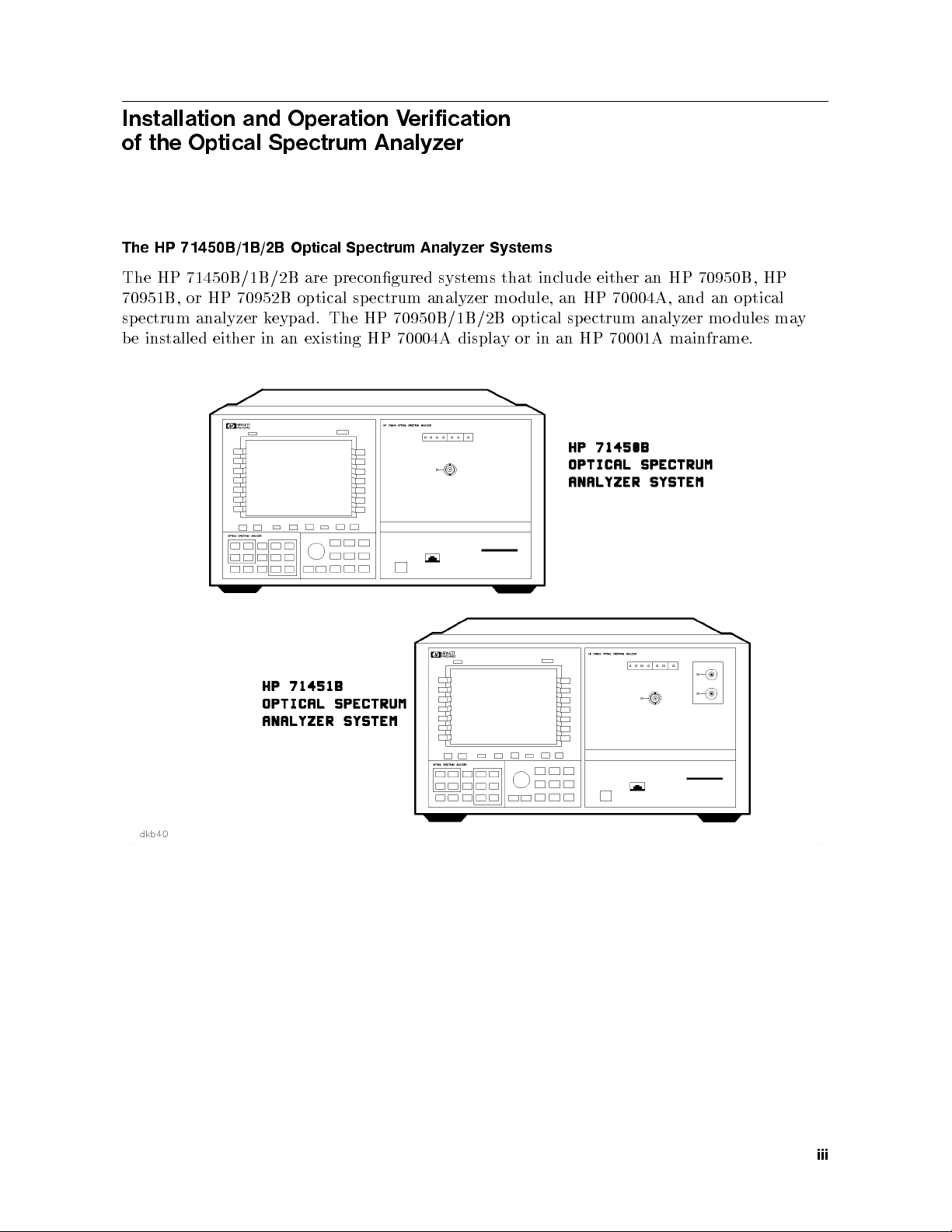
The HP 71450B/1B/2B Optical Spectrum Analyzer Systems
The HP 71450B/1B/2B are precongured systems that include either an HP 70950B, HP
70951B, or HP 70952B optical spectrum analyzer mo dule, an HP 70004A, and an optical
spectrum analyzer keypad. The HP 70950B/1B/2B optical spectrum analyzer modules may
be installed either in an existing HP 70004A display or in an HP 70001A mainframe.
iii
Page 4
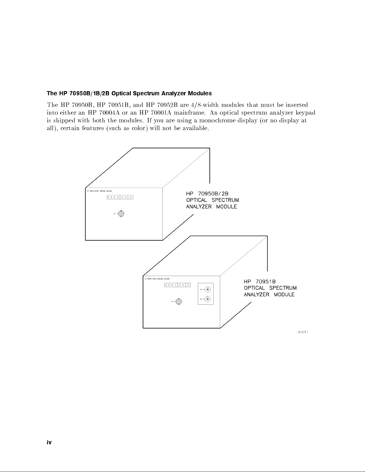
The HP 70950B/1B/2B Optical Spectrum Analyzer Modules
The HP 70950B, HP 70951B, and HP 70952B are 4/8-width mo dules that must be inserted
into either an HP 70004A or an HP 70001A mainframe. An optical sp ectrum analyzer keypad
is shipped with b oth the mo dules. If you are using a mono chrome display (or no displayat
all), certain features (such as color) will not be available.
iv
Page 5
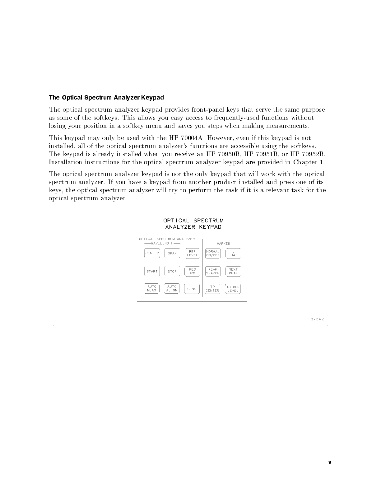
The Optical Spectrum Analyzer Keypad
The optical spectrum analyzer keypad provides front-panel keys that serve the same purpose
as some of the softkeys. This allows you easy access to frequently-used functions without
losing your p osition in a softkey menu and saves you steps when making measurements.
This keypad may only be used with the HP 70004A. However, even if this keypad is not
installed, all of the optical spectrum analyzer's functions are accessible using the softkeys.
The keypad is already installed when you receive an HP 70950B, HP 70951B, or HP 70952B.
Installation instructions for the optical spectrum analyzer keypad are provided in Chapter 1.
The optical spectrum analyzer keypad is not the only keypad that will work with the optical
spectrum analyzer. If you haveakeypad from another product installed and press one of its
eys, the
k
optical
optical
ectrum
sp
ectrum
sp
analyzer.
analyzer
will
try
to
erform
p
the
task
ttask
an
relev
a
is
it
if
for the
v
Page 6
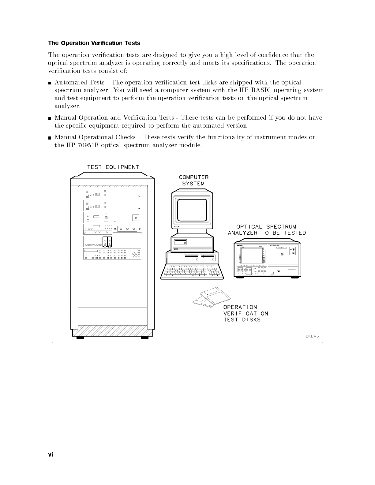
The Operation Verification Tests
The operation verication tests are designed to giveyou a high level of condence that the
optical spectrum analyzer is op erating correctly and meets its specications. The op eration
verication tests consist of:
Automated Tests - The op eration verication test disks are shipp ed with the optical
spectrum analyzer. You will need a computer system with the HP BASIC op erating system
and test equipment to p erform the operation verication tests on the optical sp ectrum
analyzer.
Manual Operation and Verication Tests - These tests can be performed if you do not have
the specic equipment required to perform the automated version.
Manual Operational Checks - These tests verify the functionality of instrument mo des on
the HP 70951B optical spectrum analyzer mo dule.
vi
Page 7

Note
In this bo ok, normal front-panel keys are indicated in
Softkeys are indicated by
NNNNNNNNNNNNNNNNNNNN
shaded
letters.
4
boxed
5
letters.
vii
Page 8

Page 9
Contents
1. Installation
Introduction . . . . . . . . . . . . . . . . . . . . . . . . . . . . . 1-1
Installation at a Glance . . . . . . . . . . . . . . . . . . . . . . . . 1-2
Installing the HP 71450B/1B/2B Optical Spectrum Analyzer System . . . . 1-4
Installing an HP 70950B/1B/2B Optical Spectrum Analyzer Mo dule . . . . 1-6
Step 1. Prepare to Install the Optical Spectrum Analyzer Mo dule. . . . . 1-6
Step 2. Check the Address of the Optical Spectrum Analyzer Mo dule. . . . 1-7
Step 3. Check the System's HP-MSIB Addresses. . . . . . . . . . . . . 1-8
Step 4. Install the Optical Sp ectrum Analyzer Module in the HP 70001A
Mainframe or the HP 70004A Display. . . . . . . . . . . . . . . . 1-10
Optional: Changing
Mo
Optional:
Optional:
Optional:
Displa
Optional:
Optional:
.
dule
Installing
Moun
Connecting
or Mainframe
y
Displa
Changing
.
the HP-MSIB
.
.
.
.
the
the
ting
the
the
ying
the
.
.
Optical
System
Optical
.
Time
Time
.
.
and
and
.
Sp
in
Sp
.
Address of
.
.
.
.
Rac
Analyzer's
k
ectrum
a
ectrum
.
.
.
.
Date
the
Date
the
the Optical
. .
.
.
.
.
.
.
Analyzer
.
.
.
.
.
.
.
.
.
.
. .
. .
Keypad
. .
.
System
.
.
.
.
.
.
.
.
.
ectrum
Sp
. .
.
.
. .
. .
the
in
.
Another
to
.
.
.
.
.
Analyzer
.
.
.
Displa
.
.
.
.
.
.
.
.
.
.
.
.
.
.
.
. .
.
1-12
.
.
1-13
.
y
1-14
.
.
1-16
.
.
1-17
.
1-18
.
.
v
Ha
ou
Y
If
2.
duction
tro
In
Problems Requiring
Exp
the
to
Optical
What
If
a
e
ect
Problem
.
.
.
Additional T
When
ectrum
Sp
During
. .
.
ou
Y
Analyzer
Installation
.
. .
ec
on
urn
T
.
.
hnical
the
Will
.
.
.
Resources
Optical
T
Not
.
.
Sp
urn On
.
.
.
.
.
ectrum
. .
.
.
.
.
.
.
Analyzer
. .
.
.
. .
.
.
.
.
.
.
.
.
.
.
. .
. .
.
.
.
.
.
If the Front-Panel LEDs Do Not Light When the Optical Spectrum Analyzer is
Turned On . . . . . . . . . . . . . . . . . . . . . . . . . . . . 2-5
If the Optical Spectrum Analyzer Front-Panel ERR LED Remains Lit or Blinks
after the Self-Test . . . . . . . . . . . . . . . . . . . . . . . . . 2-6
If Errors Are Reported on the Display. . . . . . . . . . . . . . . . . . 2-7
Lit
.
.
.
.
.
.
t Remains
.
Remain
. .
.
If
the
Self-T
Optical
est
Spectrum
.
.
.
.
Analyzer
. .
.
.
HP-IB
anel
t-P
ron
F
.
.
.
.
.
.
.
LEDs
.
.
.
If the Display HP-MSIB or the Mainframe I/O CHECK Indicator Ligh
Lit .
. . . . . . . . . .
If the Mainframe CURRENT Indicator Ligh
If the Optical Spectrum Analyzer Needs to be Returned for
To return the instrumen
. . . . . . . . . . . . . . . . . . . . . 2-10
t Remains Lit
. . . . . . . . . 2-11
Service . . . . . 2-12
t for service .
. . . . . . . . . . . . . . . .
the
after
Sales and service oces . . . . . . . . . . . . . . . . . . . . . . . 2-16
.
.
2-1
2-1
2-2
.
.
2-3
2-8
. 2-12
Contents-1
Page 10

3. Installation Reference
Introduction . . . . . . . . . . . . . . . . . . . . . . . . . . . . . 3-1
Optical Sp ectrum Analyzer Accessories . . . . . . . . . . . . . . . . . 3-2
HP-MSIB Cables . . . . . . . . . . . . . . . . . . . . . . . . . . 3-2
Connector Interfaces . . . . . . . . . . . . . . . . . . . . . . . . 3-2
Memory Cards . . . . . . . . . . . . . . . . . . . . . . . . . . . 3-2
Tools . . . . . . . . . . . . . . . . . . . . . . . . . . . . . . . 3-3
Miscellaneous Parts and Supplies . . . . . . . . . . . . . . . . . . . 3-3
Power Cables . . . . . . . . . . . . . . . . . . . . . . . . . . . . . 3-3
Serial Number and Option Labels . . . . . . . . . . . . . . . . . . . . 3-5
Serial Number Labels . . . . . . . . . . . . . . . . . . . . . . . . 3-5
Option Labels . . . . . . . . . . . . . . . . . . . . . . . . . . . 3-5
ESD Information . . . . . . . . . . . . . . . . . . . . . . . . . . . 3-6
Reducing ESD Damage . . . . . . . . . . . . . . . . . . . . . . . 3-7
Static-Safe Accessories . . . . . . . . . . . . . . . . . . . . . . . . 3-7
4. Operation Verication Testing
Introduction . . . . . . . . . . . . . . . . . . . . . . . . . . . . . 4-1
. .
. .
. .
esting
erication
eration
Op
for
are
w
ware
ou
Y
Equipmen
est
eration
Optical
the
the
the
Line
the
Default
the
the Op
are
an SRM
on
. .
ectrum
Sp
ectrum
Sp
t
an
W
erication
V
.
.
erature
emp
T
Humidit
requency
F
est
T
MS
eration
.
.
.
Analyzer's
Analyzer's
to Output
.
t
.
.
.
ectrum
Sp
.
.
.
Setting
y
Equipment
Equipmen
File's
erication
V
Hardw
the
up
Set
1.
Step
Soft
Install
2.
Step
3. Load
Step
Select
4.
Step
En
5.
Step
Select
6.
Step
Verify
7.
Step
V
8.
Step
Run
9.
Step
Optional:
Optional:
Optional:
Optional:
Optional:
Optional:
Step 1. Print the Default Equipment List . . . . . . . . . . . . . . . 4-19
Step 2. Exit the Operation Verication Software . . . . . . . . . . . . 4-19
Step 3. Load the TSCRIPT MS File . . . . . . . . . . . . . . . . . 4-19
Step 4. Edit the Test Equipment and HP-IB Address Lists . . . . . . . . 4-20
5.
Step
6.
Step
Optional:
the
the Soft
Optical
the
Optical
the
ter
Where
T
the
Accessories
the
erify
Op
the
Selecting
Adding Options
difying
Mo
difying
Mo
Selecting
Changing
the Required
Edit
TSCRIPT
the
e
v
Sa
Running
V
or HFS
.
.
.
.
.
.
ests
T
.
.
Setting
.
Edits
Hard Disk
.
.
.
Mo
est
T
est
T
the
.
.
.
.
.
.
.
.
Analyzer's Address
.
.
.
.
.
.
.
. .
.
.
. .
Lists
t
.
ests
T
T
.
.
.
.
.
.
del
Information
Results
.
.
.
.
.
.
.
.
.
. .
.
.
.
.
.
.
.
.
.
.
.
.
.
. .
. .
.
.
. .
.
.
.
.
.
.
.
a
from
.
.
. .
.
.
.
.
.
.
.
.
.
.
.
. .
.
.
.
.
.
.
.
.
.
.
.
.
. .
.
.
. .
.
.
.
. .
.
.
.
. .
Flexible
.
.
.
.
.
.
.
.
.
.
.
.
.
.
.
. .
.
.
.
. .
.
.
.
.
.
.
.
.
.
.
.
.
.
. .
. .
.
.
.
.
.
.
.
.
Disk
.
.
. .
.
.
. .
.
.
.
.
.
.
.
.
.
.
. .
.
. .
. .
.
.
.
.
.
.
.
.
Driv
4-3
.
.
.
. 4-10
.
.
.
.
. 4-17
.
.
.
.
e 4-22
4-4
4-6
4-7
4-8
4-9
4-12
4-13
4-14
4-15
4-16
4-18
4-19
4-21
4-21
5. Operation V
Introduction
System Requiremen
Computer Hardw
Operating System . . . . . . . . . . . . . . . . . . . . . . . . . . 5-3
Computer Keyboard Compatibility and Mouse Operation . . . . . . . . . 5-4
Using
Using
Using
Recommended
Contents-2
erication T
. . . . . . . . . . . . .
46021A
HP
an
98203C
HP
an
T
with
est
Mouse
a
est Reference
. . . . . . . . . . . . . . . . . . . . . . . . 5-2
ts .
are .
. . . . . . . . . . . . . .
Keyb
Keyb
Series 300
a
Equipmen
oard
oard
t
with
with
Computer
.
.
.
. . . . . . . . . . . . . . . . 5-1
. . . . . . . . . . 5-2
.
.
.
.
.
a
a
.
Series
Series
.
.
.
.
300
300
.
.
Computer
Computer
.
.
.
.
.
.
.
.
.
.
.
.
.
. .
.
.
.
.
.
.
.
.
. .
.
.
.
.
.
.
.
.
.
.
5-4
5-4
5-5
5-5
Page 11
Precision Resistor and RCNetwork . . . . . . . . . . . . . . . . . . . 5-8
6. Operation Verication Test Descriptions
Introduction . . . . . . . . . . . . . . . . . . . . . . . . . . . . . 6-1
Automated Test Pro cedures . . . . . . . . . . . . . . . . . . . . . . 6-3
Wavelength Accuracy (Automated) . . . . . . . . . . . . . . . . . . . 6-4
Equipment. . . . . . . . . . . . . . . . . . . . . . . . . . . . . 6-4
Equipment Setup . . . . . . . . . . . . . . . . . . . . . . . . . . 6-4
Description . . . . . . . . . . . . . . . . . . . . . . . . . . . . . 6-5
In Case of Failure . . . . . . . . . . . . . . . . . . . . . . . . . . 6-5
Resolution Bandwidth Accuracy . . . . . . . . . . . . . . . . . . . . 6-6
Equipment. . . . . . . . . . . . . . . . . . . . . . . . . . . . . 6-6
Equipment Setup . . . . . . . . . . . . . . . . . . . . . . . . . . 6-6
Description . . . . . . . . . . . . . . . . . . . . . . . . . . . . . 6-6
In Case of Failure . . . . . . . . . . . . . . . . . . . . . . . . . . 6-6
Absolute Amplitude Accuracy . . . . . . . . . . . . . . . . . . . . . 6-7
Equipment. . . . . . . . . . . . . . . . . . . . . . . . . . . . . 6-7
Equipment Setup . . . . . . . . . . . . . . . . . . . . . . . . . . 6-7
.
.
.
.
.
.
.
.
. .
. .
. .
.
.
.
.
.
.
.
.
.
.
.
.
.
Description
Case
In
Fidelity
Scale
Equipmen
Equipmen
Description
Case
In
Flatness
Equipmen
Equipmen
Description
Case
In
Sensitivit
Equipmen
Description
In Case of Failure . . . . . . . . . . . . . . . . . . . . . . . . . . 6-14
Dynamic Range (Automated) . . . . . . . . . . . . . . . . . . . . . . 6-15
Equipment. . . . . . . . . . . . . . . . . . . . . . . . . . . . . 6-15
Equipment Setup . . . . . . . . . . . . . . . . . . . . . . . . . . 6-15
Description
Case
In
Curren
White Light Output Power, Option 002 . . . . . . . . . . . . . . . . . 6-19
P
t
Equipment.
Equipment Setup . . . . . . . . . . . . . . . . . . . . .
Description .
In Case of F
Equipment. . . . . . . . . . . . . . . . . . . . . . . . . . . . . 6-19
Equipment Setup . . . . . . . . . . . . . . . . . . . . . . . . . . 6-19
Description
Case
In
olarization
Equipmen
.
ailure
F
of
. .
.
t
Setup
t
.
ailure
of F
erication
V
.
t
Setup
t
. .
ailure
F
of
.
.
y
Setup
t
.
.
ailure
F
of
Source, Option
ailure .
.
ailure
F
of
Dep
.
t
.
. .
.
.
.
.
.
.
.
.
.
.
.
.
.
.
.
.
.
.
.
.
. .
.
.
. .
.
.
. . . . . . . .
. . . . . . . . . .
. .
.
.
enden
.
.
.
.
.
.
.
.
.
. .
. .
. .
. .
.
.
.
.
.
.
.
.
.
.
.
.
.
.
.
.
. .
. .
.
.
.
.
.
.
.
.
.
.
.
.
.
.
.
.
.
. .
. .
.
.
.
.
.
.
.
.
.
.
.
.
.
.
.
.
.
.
.
.
. .
.
.
.
.
.
.
.
.
.
.
.
.
.
.
.
.
.
.
.
.
.
.
.
.
.
.
.
.
.
.
.
.
.
.
.
.
.
.
.
.
.
.
.
. .
.
.
.
.
.
.
.
.
.
.
.
.
.
.
.
.
.
.
.
. .
.
.
.
.
.
.
.
.
.
.
.
.
.
.
.
.
.
.
.
. .
. .
.
.
.
.
.
.
.
.
.
.
.
. .
. .
. .
. .
.
.
.
.
.
.
.
.
.
.
.
.
. .
. .
. .
. .
.
.
.
.
.
.
.
.
.
.
.
.
.
.
.
.
. .
. .
.
.
.
.
. .
.
.
.
.
.
.
.
.
.
.
. .
.
.
.
.
.
.
.
.
.
.
.
. .
.
.
.
.
. .
.
.
.
.
.
.
.
.
.
.
.
.
.
.
.
.
System
. .
. . . . . . . . . . . . . . . . . . . . 6-17
. . . . . . . . . . . . . . . . . . 6-18
.
.
.
.
.
.
.
.
.
.
.
.
. .
.
.
.
.
.
.
.
.
.
.
.
003
.
.
.
.
.
.
Accuracy
.
.
.
.
Option
,
.
.
001
. . . . . . . . . . . . . . . . . .
.
.
Loss
t
.
.
.
.
.
.
.
.
.
. .
. .
. .
.
.
.
.
.
.
.
.
. .
.
.
.
.
.
.
.
.
.
.
.
.
.
.
.
.
.
. .
.
.
.
.
.
.
.
.
.
.
.
. .
.
.
.
.
.
.
.
.
.
.
.
.
.
.
.
.
.
. .
. .
.
.
.
.
.
.
.
.
.
.
.
.
.
.
.
.
.
.
.
.
.
.
.
.
.
.
.
.
.
.
.
.
.
.
. .
.
.
.
.
.
.
.
.
.
.
.
.
.
.
.
.
.
.
.
.
.
.
. . . . . 6-17
. . . . . . . 6-18
. .
.
.
.
.
.
.
.
.
.
.
.
.
.
.
.
.
. .
.
.
.
.
.
.
.
.
.
.
.
.
.
.
.
.
.
.
.
.
.
.
.
.
.
. 6-14
.
.
.
.
.
6-8
6-8
6-9
6-9
6-9
6-10
6-10
6-11
6-11
6-11
6-12
6-13
6-14
6-14
6-16
6-16
6-17
6-20
6-20
6-21
6-21
Contents-3
Page 12

Equipment setup . . . . . . . . . . . . . . . . . . . . . . . . . . 6-21
Description . . . . . . . . . . . . . . . . . . . . . . . . . . . . . 6-22
In Case of Failure . . . . . . . . . . . . . . . . . . . . . . . . . . 6-23
Manual Test Procedures . . . . . . . . . . . . . . . . . . . . . . . . 6-24
Wavelength Accuracy (Manual) . . . . . . . . . . . . . . . . . . . . . 6-25
Equipment. . . . . . . . . . . . . . . . . . . . . . . . . . . . . 6-25
EquipmentSetup . . . . . . . . . . . . . . . . . . . . . . . . . . 6-25
Procedure . . . . . . . . . . . . . . . . . . . . . . . . . . . . . 6-26
Dynamic Range (Manual) . . . . . . . . . . . . . . . . . . . . . . . 6-27
Equipment. . . . . . . . . . . . . . . . . . . . . . . . . . . . . 6-27
EquipmentSetup . . . . . . . . . . . . . . . . . . . . . . . . . . 6-27
Procedure . . . . . . . . . . . . . . . . . . . . . . . . . . . . . 6-27
Flatness (Manual) . . . . . . . . . . . . . . . . . . . . . . . . . . . 6-29
Equipment. . . . . . . . . . . . . . . . . . . . . . . . . . . . . 6-29
EquipmentSetup . . . . . . . . . . . . . . . . . . . . . . . . . . 6-29
Procedure . . . . . . . . . . . . . . . . . . . . . . . . . . . . . 6-31
Manual Operational Checks for the HP 70951B Optical Sp ectrum Analyzer
Module . . . . . . . . . . . . . . . . . . . . . . . . . . . . . . 6-32
. 6-33
. .
.
.
.
.
.
.
.
.
.
.
.
.
.
.
.
.
.
.
.
.
.
.
. .
.
.
.
.
.
.
.
. .
.
.
detector
.
.
.
.
.
.
.
6-33
.
.
.
.
.
. .
. .
. .
. .
.
.
.
.
.
.
.
.
6-33
.
.
.
.
.
.
.
.
.
.
.
.
. .
. .
.
.
.
.
.
6-33
.
.
.
.
.
.
.
.
.
.
.
.
.
.
.
.
.
.
.
.
.
6-35
.
.
.
. .
. .
.
.
.
.
.
.
.
.
.
.
.
.
.
.
. 6-36
.
.
.
.
.
.
.
.
.
.
.
k
Input
. .
.
.
.
.
.
.
.
.
.
.
.
.
.
.
Chec
6-36
.
.
.
.
.
.
.
.
.
.
.
.
.
.
.
.
.
6-36
.
.
.
.
.
.
.
.
.
.
.
.
.
.
.
.
.
6-36
.
.
.
.
.
.
. .
.
.
.
.
.
.
.
.
.
6-37
.
.
.
.
.
.
.
.
.
.
.
.
.
. .
.
.
Transimp
Equipmen
Equipmen
cedure
Pro
Case of
In
hromator
c
Mono
Equipmen
Equipmen
cedure
Pro
Case
In
edance Input
.
.
.
t
Setup
t
.
.
.
ailure
F
Output/Photo
.
.
.
t
Setup
t
.
.
.
ailure
F
of
Check
.
.
.
.
. .
.
.
.
.
.
.
.
.
.
.
.
Index
Contents-4
Page 13

Figures
2-1. Optical Spectrum Analyzer FrontPanel (HP 71451B Shown) . . . . . . . 2-2
2-2. Line Voltage Selector . . . . . . . . . . . . . . . . . . . . . . . . 2-3
2-3. Line Fuse Removal and Replacement . . . . . . . . . . . . . . . . . 2-4
2-4. Optical Spectrum Analyzer FrontPanel LEDs (HP 71451B Shown) . . . . 2-5
2-5. Optical Spectrum Analyzer Error Information (HP 71451B Shown) . . . . 2-6
2-6. Optical Spectrum Analyzer Displayed Errors (HP 71451B Shown) . . . . . 2-7
2-7. Optical Spectrum Analyzer HP-IB LEDs (HP 71451B Shown) . . . . . . 2-8
2-8. HP-MSIB and I/O CHECK Indicator Lights . . . . . . . . . . . . . . 2-10
2-9. Current Indicator Light . . . . . . . . . . . . . . . . . . . . . . . 2-11
2-10. Packaging Materials for HP 70950B/1B/2B Mo dules . . . . . . . . . . 2-13
.
.
.
.
.
.
.
. .
Materials
aging
k
ac
P
2-11.
.
.
.
.
.
.
.
.
.
.
.
.
.
.
.
.
.
.
.
. .
elength
v
a
t
t
Ligh
Serial-Numb
orkstation
W
.
.
.
.
.
.
.
.
.
.
.
.
.
.
.
.
.
.
.
.
.
.
.
.
.
. .
.
.
.
.
.
.
.
.
.
. .
.
.
.
. .
. .
Accuracy
Bandwidth
yT
est Setup
Source
Source
Output
t
Module
3-1.
Static-Safe
3-2.
.
4-1.
.
4-2.
.
4-3.
. .
4-4.
.
4-5.
.
4-6.
.
4-7.
4-8. .
.
4-9.
4-10.
4-11. .
4-12. . . . . . . . . . . . . . . . . . . . . . . . . . . . . . . . . . . 4-17
4-13. . . . . . . . . . . . . . . . . . . . . . . . . . . . . . . . . . . 4-18
4-14. . . . . . . . . . . . . . . . . . . . . . . . . . . . . . . . . . . 4-18
6-10. Dynamic Range Test System Alignment Setup . . . . . . . . . . . . . 6-15
6-11.
6-12.
6-13.
6-14.
.
5-1. Precision Resistor and RCNetwork Schematic Diagram . . . . . . . . . 5-8
6-1. Wavelength Accuracy Test Setup 1 . . . . . . . . . . . . . . . . . . 6-4
W
6-2.
Resolution
6-3.
6-4. Absolute Amplitude Accuracy Calibration Setup
6-5. Absolute Amplitude Accuracy T
6-6. Scale Fidelit
6-7. Flatness Calibration Setup .
6-8. Flatness T
6-9. SensitivityTest Setup . . . . . . . . . . . . . . . . . . . . . . . . 6-14
Dynamic Range
Curren
Curren
White
for HP
er and
.
.
.
.
.
.
.
. .
.
.
.
.
.
.
.
.
.
.
.
.
.
.
.
.
.
.
. .
.
.
.
est Setup
. .
Setup
est
T
Calibration
Setup
est
T
P
71450B/1B/2B Systems
.
.
els
Option
.
.
. .
.
. .
.
.
.
.
.
.
.
.
.
.
.
. .
.
.
.
.
.
.
.
.
.
.
. .
. .
.
.
.
Setup
Test
Accuracy
. . . . . . . . . . . . . . . . . . . . . . . 6-9
. . . . . . . . . . . . . . . . . . . . . . . 6-12
Setup
.
T
er
ow
Lab
.
.
.
.
.
.
.
.
.
.
.
.
.
.
. .
.
.
.
.
.
. .
.
.
.
.
.
.
.
.
.
.
.
.
.
.
.
.
.
. .
.
.
.
.
.
.
.
.
.
.
.
.
.
.
.
.
.
.
.
.
.
.
.
.
.
.
.
.
.
.
.
. .
. .
.
.
.
.
.
.
.
.
.
.
.
.
.
.
.
.
.
.
.
.
.
.
2
Setup
est
T
est Setup
. . . . . . . . . . . . . .
.
.
.
.
.
.
.
.
.
.
.
.
.
est
Setup
1
.
. . . . . . . . . . . .
.
.
.
.
.
.
.
. .
.
.
.
. .
. 3-5
.
.
.
.
.
.
.
.
.
.
.
.
.
.
.
.
. .
. .
.
.
.
.
.
.
.
.
.
.
.
.
.
.
.
.
.
.
.
.
.
.
.
.
.
.
.
.
.
.
.
. .
.
.
.
.
.
.
.
.
.
.
.
.
.
.
.
.
.
.
. .
.
.
.
.
.
.
.
.
.
.
.
.
.
.
.
.
.
.
.
.
.
.
.
.
.
.
.
.
.
.
.
.
.
. .
.
.
.
.
.
.
.
.
.
.
.
.
.
.
.
.
. .
. .
.
.
.
.
.
.
.
.
.
.
.
.
.
.
. 4-15
. .
.
.
.
.
.
.
.
.
.
.
.
.
. .
. .
. .
. .
.
.
.
.
.
.
.
.
.
.
. .
.
.
.
.
.
.
.
.
.
.
.
. .
.
.
.
.
. . . . . . . . . . . . 6-7
. . . 6-8
. . . . . . . 6-11
. 6-16
.
.
.
.
.
.
.
.
.
.
.
.
.
.
.
.
. .
.
.
.
.
.
.
.
.
.
.
.
.
.
.
.
.
.
.
.
.
.
.
.
.
.
.
.
.
.
.
.
.
.
2-14
3-6
4-7
4-8
4-9
4-10
4-12
4-13
4-13
4-14
4-15
4-16
6-4
6-6
6-17
6-18
6-19
Contents-5
Page 14

6-15. White Light Output Power Test Setup 2 . . . . . . . . . . . . . . . . 6-20
6-16. PDL System Accuracy Test Setup . . . . . . . . . . . . . . . . . . . 6-21
6-17. Manual Wavelength Accuracy Test Setup . . . . . . . . . . . . . . . 6-25
6-18. Manual Dynamic Range Test Setup . . . . . . . . . . . . . . . . . . 6-27
6-19. Manual Flatness Test Setup 1 . . . . . . . . . . . . . . . . . . . . 6-29
6-20. Manual Flatness Test Setup 2 . . . . . . . . . . . . . . . . . . . . 6-30
6-21. Transimp edance Input Check Setup . . . . . . . . . . . . . . . . . . 6-33
6-22. Monochromator Output/Photodetector Input Check Setup . . . . . . . . 6-36
Contents-6
Page 15
Tables
3-1. Power Cables . . . . . . . . . . . . . . . . . . . . . . . . . . . . 3-4
3-2. Static-Safe Accessories . . . . . . . . . . . . . . . . . . . . . . . . 3-7
4-1. Test EquipmentVariable Names . . . . . . . . . . . . . . . . . . . 4-20
5-1. Required Computer Hardware . . . . . . . . . . . . . . . . . . . . 5-2
5-2. Required BASIC 5.13 Language Extensions . . . . . . . . . . . . . . 5-3
5-3. Equivalent Keys for the Operation Verication Tests . . . . . . . . . . 5-4
5-4. Recommended Test Equipment . . . . . . . . . . . . . . . . . . . . 5-6
5-5. Precision Resistor and RCNetwork Parts List . . . . . . . . . . . . . 5-8
6-1. Knob Settings for the Polarization Controller . . . . . . . . . . . . . . 6-22
Contents-7
Page 16

Page 17
1
Installation
Introduction
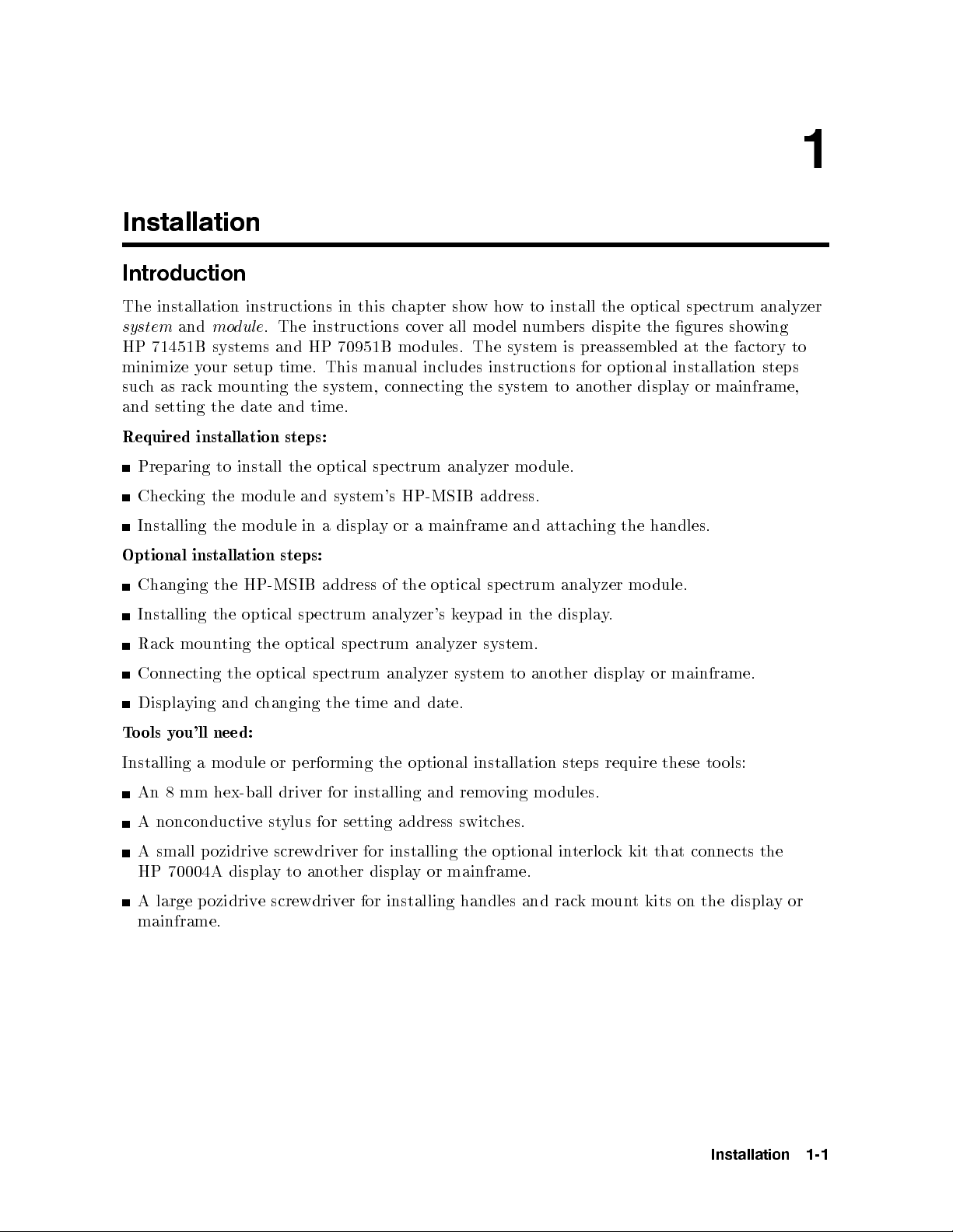
The installation instructions in this chapter showhow to install the optical sp ectrum analyzer
system
and
module
. The instructions cover all model numbers dispite the gures showing
HP 71451B systems and HP 70951B modules. The system is preassembled at the factory to
minimize your setup time. This manual includes instructions for optional installation steps
suchasrack mounting the system, connecting the system to another display or mainframe,
and setting the date and time.
Required installation steps:
dule.
Preparing
to
install
the
optical
ectrum
sp
analyzer
mo
king
Chec
Installing the
Optional
installation
Changing
Installing
moun
k
Rac
Connecting
ying
Displa
ou'll need:
ols y
o
T
the
the
the
ting
the
and c
dule
mo
module
steps:
HP-MSIB
the
sp
optical
optical
optical
hanging the
and system's
displa
a
in
address
ectrum
sp
ectrum
sp
HP-MSIB address.
mainframe
a
or
y
optical
the
of
analyzer's
ectrum
analyzer system.
analyzer
date.
and
time
eypad
k
system
ectrum
sp
and
the
in
another
to
attac
analyzer
displa
hing
.
y
display
handles.
the
dule.
mo
or mainframe.
Installing a module or p erforming the optional installation steps require these tools:
An 8 mm hex-ball driver for installing and removing modules.
A nonconductivestylus for setting address switches.
screwdriv
displa
e
another
to
y
A
HP
small
70004A
ozidriv
p
A large pozidrive screwdriv
optional
er for
displa
installing
y
the
mainframe.
or
er for installing handles and rac
in
kmoun
t kits on the displa
connects
that
kit
k
c
terlo
mainframe.
the
yor
Installation
1-1
Page 18
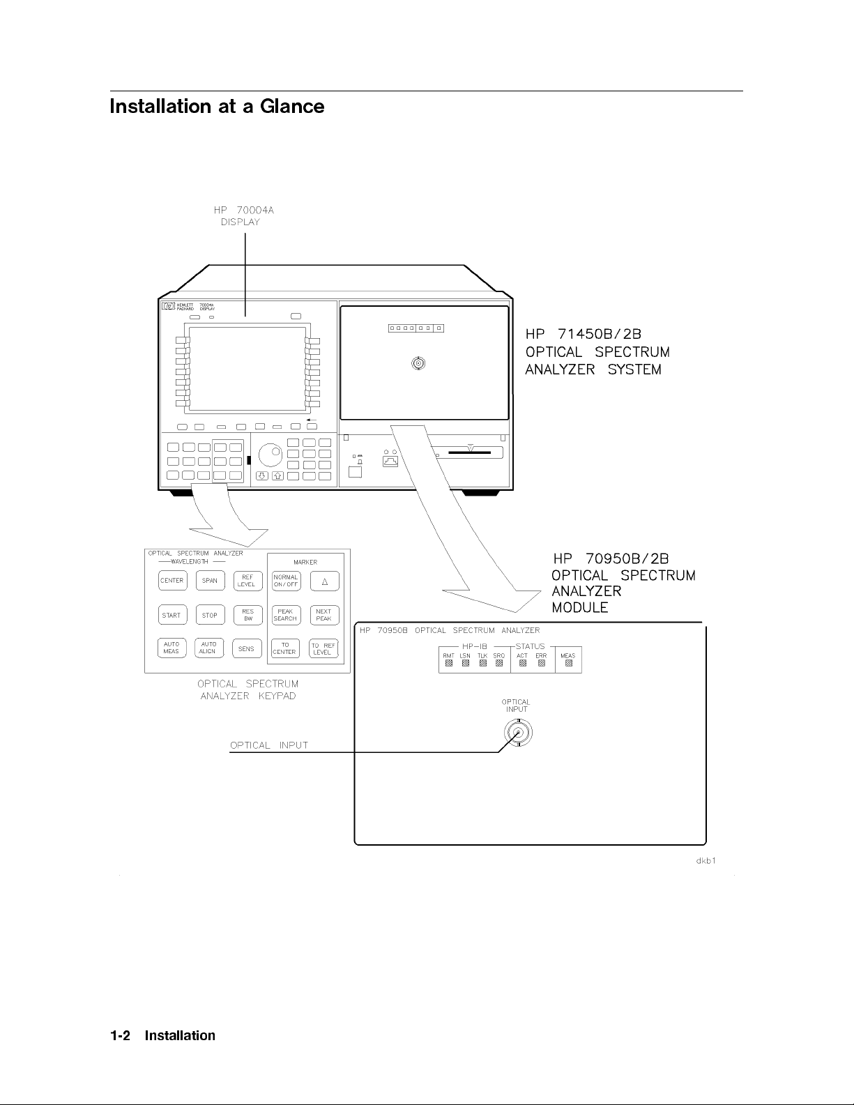
Installation at a Glance
1-2
Installation
Page 19

Installation
1-3
Page 20
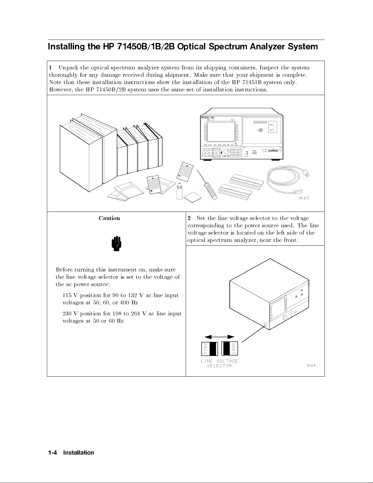
Installing the HP 71450B/1B/2B Optical Spectrum Analyzer System
1
Unpack the optical spectrum analyzer system from its shipping containers. Inspect the system
thoroughly for any damage received during shipment. Make sure that your shipment is complete.
Note that these installation instructions show the installation of the HP 71451B system only.
However, the HP 71450B/2B system uses the same set of installation instructions.
oltage
v
Caution
Set
2
corresp
oltage
v
optical
line
the
onding
selector
ectrum
sp
oltage
v
the
to
lo
is
analyzer,
selector
o
p
cated
er
w
on
near
to
source
the
the
the
used.
left
side
fron
t.
The
of
line
the
e
mak
on,
is
t
to
set
132 V
the
ac line
oltage
v
Before
line
the
ac p
the
115
turning
oltage
v
er
w
o
osition
p
V
this
selector
source:
for
instrumen
90 to
voltages at 50, 60, or 400 Hz
230 V position for 198 to 264 V ac line input
voltages at 50 or 60 Hz
sure
of
input
1-4
Installation
Page 21
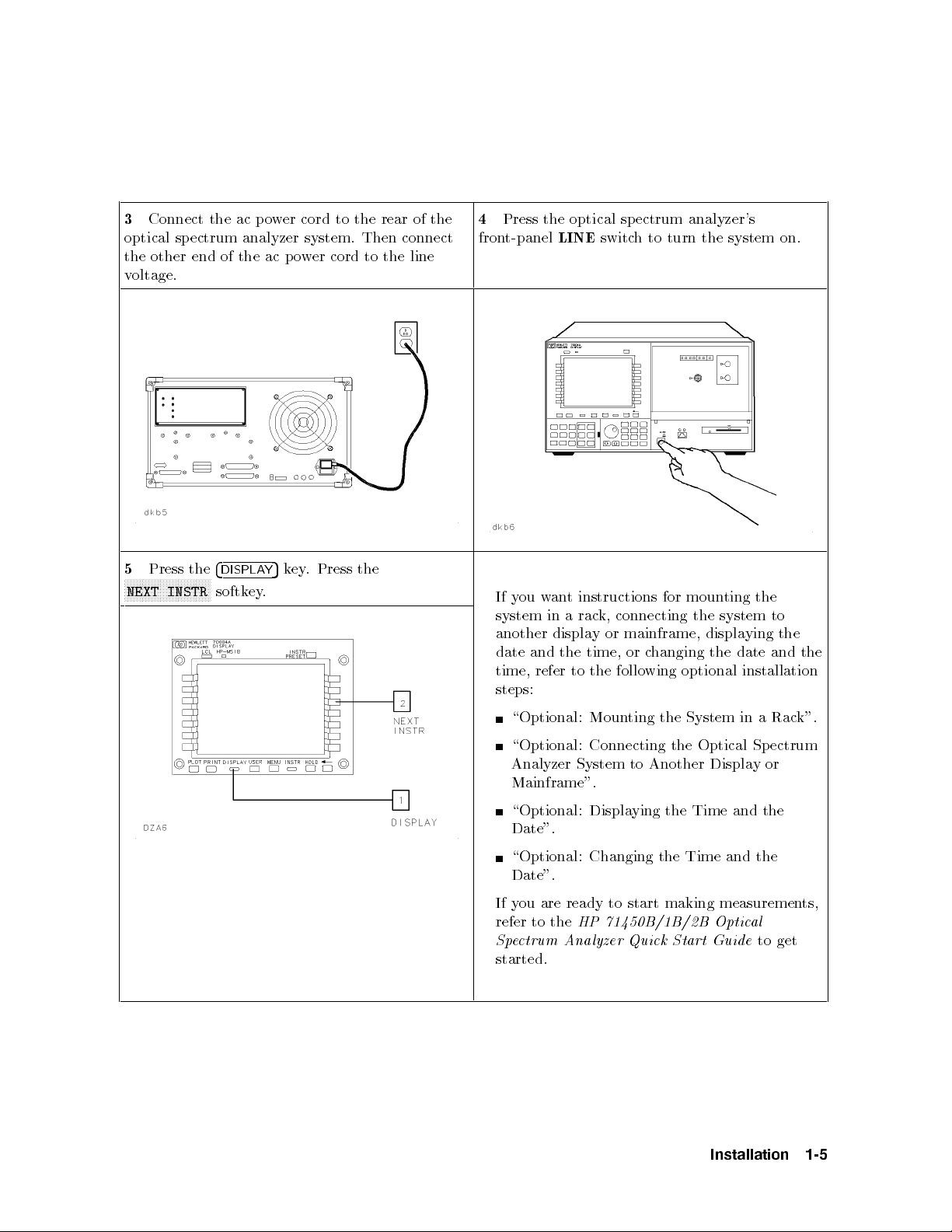
3
Connect the ac p ower cord to the rear of the
optical spectrum analyzer system. Then connect
the other end of the ac power cord to the line
voltage.
4
Press the optical sp ectrum analyzer's
front-panel
LINE
switch to turn the system on.
5
N
N
N
N
N
N
N
NEXT
Press
N
N
N
N
N
N
N
the
N
N
N
N
N
N
NN
N
INSTR
N
N
N
N
N
N
4
DISPLA
softk
ey
the
Press
.
ey
k
5
Y
.
ou
y
If
system
another
and
date
time,
an
w
in
displa
refer
instructions
t
k,
rac
a
or
y
time,
the
the
to
connecting
follo
for moun
mainframe,
hanging
c
or
optional
wing
the
displa
ting
system to
ying
date
the
installation
the
the
and
the
steps:
ting
\Optional:
Moun
\Optional: Connecting
System
the
the Optical
in
ectrum
Sp
k".
Rac
a
Analyzer System to Another Display or
Mainframe".
\Optional: Displaying the Time and the
Date".
the
\Optional:
Changing
the Time
and
Date".
ou are ready to start making measuremen
If y
refer to the
Spectrum A
HP 71450B/1B/2B Optic
nalyzer Quick Start Guide
al
ts,
to get
started.
Installation
1-5
Page 22

Installing an HP 70950B/1B/2B Optical Spectrum Analyzer Module
Step 1. Prepare to Install the Optical Spectrum Analyzer Module.
1
Unpack the optical spectrum analyzer module from its shipping containers. Insp ect the module
thoroughly for any damage received during shipment. Make sure that your shipment is complete.
Note that these installation instructions only show the installation of the HP 70951B module.
However, the HP 70950B/2B mo dules uses the same set of installation instructions.
2
that
the
Install
the
will
ou
y
appropriate
instructions.
mainframe
using
e
b
installation
with
or
the
the
man
displa
dule.
mo
ual
for
y
Refer
to
The
3
dules.
mo
for
slots
installed
en
op
to
70950B/1B/2B
HP
eac
They
installation.
dules
mo
necessary
the
require
h
from
Remo
the
slots.
are
four
or
e
v
displa
4/8-width
adjacen
previously
e
v
mo
mainframe
or
y
t,
empt
y
1-6
Installation
Page 23

Step 2. Check the Address of the Optical Spectrum Analyzer Module.
1
Locate the eight address switches on the top of
the mo dule. These switches are factory preset to
row address 0 and column address 23.
When using the HP 70950B/1B/2B optical
spectrum analyzer mo dule with other
factory-preset mo dules, the factory-preset
address of the HP 70950B/1B/2B does not need
to b e changed.
However, if two optical spectrum analyzers are
in the system, you must change the address of
one of them.
the
er
v
unique
a
hes.
o
8-bit
determined
is
three
The
the
ro
binary
most
w
device
h
Eac
HP-MSIB
HP-MSIB
eigh
the
y
b
signican
that
bus
address.
address
t
t bits
comm
ust
m
(MSB)
unicates
e
v
ha
This
switc
determine
address
address. The ve least signicant bits (LSB)
determine the column address. This manual
refers to the decimal equivalent of the binary
address.
Determine
2
address
the
equiv
alen
t.
the
switc
hes
mo
dule's
calculating
and
address
b
the
lo
y
oking
decimal
at
Installation
1-7
Page 24
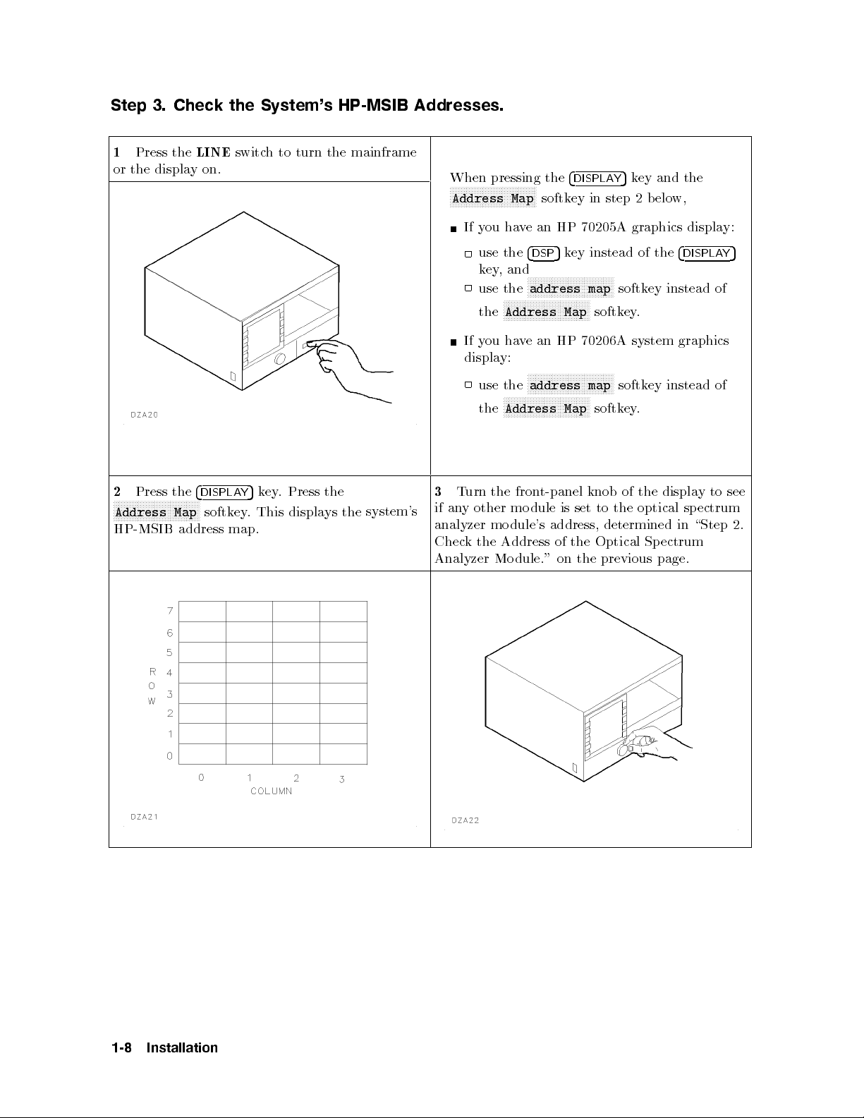
Step 3. Check the System's HP-MSIB Addresses.
1
Press the
or the displayon.
LINE
switch to turn the mainframe
When pressing the
NNNNNNNNNNNNNNNNNNNNNNNNNNNNNNNN
Address Map
If you have an HP 70205A graphics display:
4
DISPLAY
5
key and the
softkey in step 2 below,
Press
2
N
N
N
N
N
N
N
N
N
N
N
N
NN
NN
N
N
N
Address
HP-MSIB
the
N
N
N
N
N
N
N
N
N
Map
address
4
DISPLA
N
N
N
N
softk
5
Y
.
ey
map.
ey
k
This
Press
.
displa
the
ys
the
system's
use the
key,and
use the
the
4
5
key instead of the
DSP
NNNNNNNNNNNNNNNNNNNNNNNNNNNNNNNN
address map
NNNNNNNNNNNNNNNNNNNNNNNNNNNNNNNN
Address Map
softkey instead of
softkey.
If you have an HP 70206A system graphics
display:
NNNNNNNNNNNNNNNNNNNNNNNNNNNNNNNN
urn
T
3
other
y
an
if
analyzer
the
k
Chec
Analyzer
use the
the
address map
NNNNNNNNNNNNNNNNNNNNNNNNNNNNNNNN
Address Map
t-panel
fron
the
dule
mo
address,
dule's
mo
Address
dule."
Mo
of
on
set
is
the
softkey instead of
softkey.
of
knob
the
to
determined
Optical
previous
the
the
optical
Sp
page.
4
DISPLAY
displa
sp
in
ectrum
to
y
ectrum
\Step
5
see
2.
1-8
Installation
Page 25

4
Press the
LINE
display to turn it o.
switch of the mainframe or the
If no other mo dule is set to the same HP-MSIB
address as the optical spectrum analyzer
module, continue at \Step 4. Install the Optical
Spectrum Analyzer Module in the HP 70001A
Mainframe or the HP 70004A Display." on the
following page.
there
If
can
ou
y
mo
other
ou
y
If
\Optional:
ou w
y
If
dule.
mo
Optical
on the
another
is
the
hange
c
assigned
dule
c
to
t
an
w
Changing
c
to
ant
After the
ectrum Analyzer
Sp
following
dule
mo
HP-MSIB
to
hange
the
hange
address of
page.
same
at
that
address
the
HP-MSIB
address
the
the
address
address.
that
Module
HP-MSIB
either
the
of
Address
the
of
dule
mo
the
in
the
of
optical
of
other
has
HP
address
optical
ectrum
sp
Optical
the
dule,
mo
c
een
b
70001A
the
as
ectrum
sp
analyzer
refer
hanged,
Mainframe
optical
ectrum
Sp
to
con
analyzer
mo
installation
the
ue
tin
or
ectrum
sp
dule,
Analyzer
\Step
at
HP
the
analyzer
dule
mo
contin
Mo
man
4.
70004A
of
or
at
ue
dule".
ual
Install
Displa
module,
the
that
for
the
y
."
Installation
1-9
Page 26

Step 4. Install the Optical Spectrum Analyzer Module in the HP 70001A
Mainframe or the HP 70004A Display.
1
Open the front-panel door on the mainframe
or the display.
2
Slide the optical sp ectrum analyzer mo dule
into the mainframe or the display.
Press
3
tening
tigh
hex-ball
against
the
er
driv
the
hex-n
(HP
mo
ut
part
dule fron
with the
h
latc
um
n
t panel
8710-1651).
ber
while
8mm
4
or
Close
the
the
displa
fron
.
y
t-panel
door
on the
mainframe
1-10
Installation
Page 27
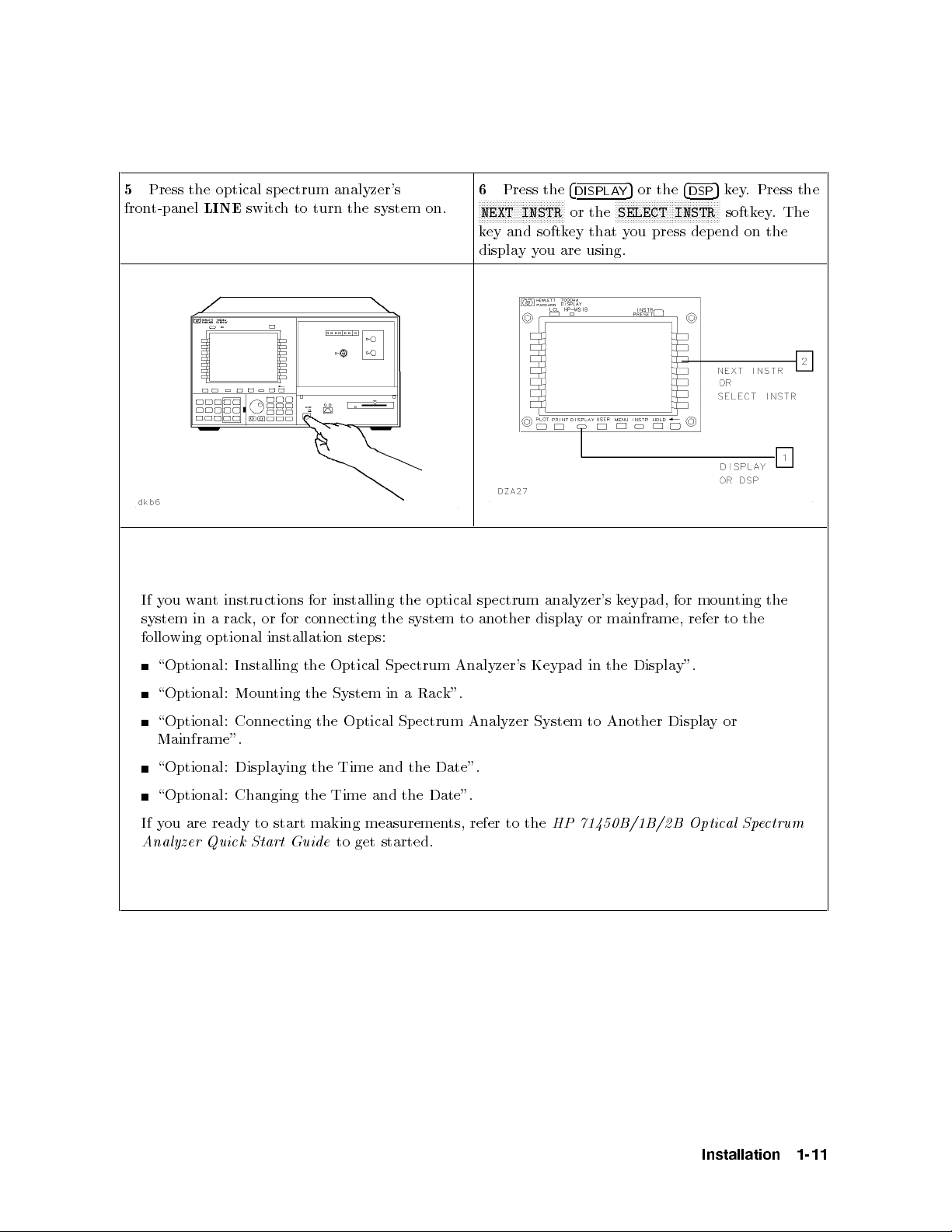
5
Press the optical sp ectrum analyzer's
front-panel
y
If
system
follo
ou
wing
LINE
an
w
in
optional
t
a
switch to turn the system on.
installing
instructions
or
k,
rac
for
connecting
for
installation
steps:
the
the
system
6
NNNNNNNNNNNNNNNNNNNNNNNNNNNNN
key and softkey that you press depend on the
displayyou are using.
optical sp
to another
Press the
NEXT INSTR
ectrum
analyzer's
displa
4
DISPLAY
NNNNNNNNNNNNNNNNNNNNNNNNNNNNNNNNNNN
or the
SELECT INSTR
k
mainframe,
or
y
5
or the
eypad,
for
4
5
key. Press the
DSP
softkey.The
moun
to
refer
ting
the
the
\Optional:
\Optional:
\Optional:
Installing
ting
Moun
Connecting
the
the
Optical
System
the
Optical
Sp
in
Sp
ectrum
Rac
a
ectrum
Analyzer's
k".
Analyzer
Keypad
System
Mainframe".
\Optional: Displaying the Time and the Date".
\Optional: Changing the Time and the Date".
If you are ready to start making measurements, refer to the
Analyzer Quick Start Guide
to get started.
y".
Displa
the
in
or
y
Another
to
Displa
HP 71450B/1B/2B Optical Spectrum
Installation
1-11
Page 28

Optional: Changing the HP-MSIB Address of the Optical Spectrum
Analyzer Module
1
Locate the eight HP-MSIB address switches on
top of the mo dule. These switches are factory
preset to row address 0 and column address 23.
Each device that communicates over the
HP-MSIB bus must have a unique 8-bit binary
HP-MSIB address. This address is determined
by the eight address switches. The three most
signicant bits (MSB) determine the row
address. The ve least signicant bits (LSB)
determine the column address. This manual
refers to the decimal equivalent of the binary
address.
Only the modules and the stand-alone
instruments that have addresses in row 0 can
communicate over the HP-IB bus.
device
is
No
useful
for
Address
yb
ma
thin,
A
setting
is
31
0,
this
to
set
e
nonconductiv
address
the
illegal
an
address.
switc
e
st
ylus
hes.
address.
the
Set
2
HP-MSIB
assigned
dule
mo
address
address
to
switc
in
an
ro
an
to
dule
mo
the
of
hes
a
e
v
ha
not
es
do
that
0
w
column.
that
in
w
ro
y
Con
Sp
tin
ectrum
Mainframe or
ue
at
\Step
Analyzer
the HP
4.
Mo
Install
dule
70004A
the
in
Displa
Optical
the
HP
70001A
.".
y
1-12
Installation
Page 29
Optional: Installing the Optical Spectrum Analyzer's Keypad
in the Display
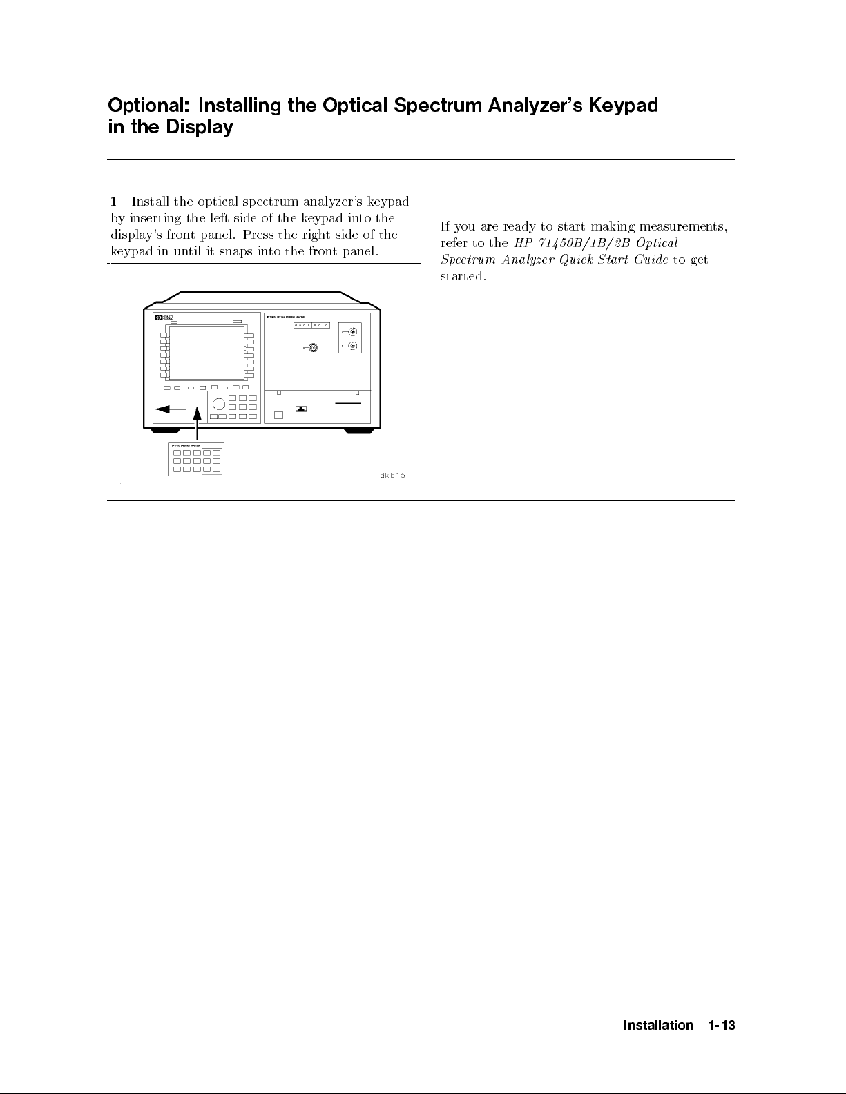
1
Install the optical sp ectrum analyzer's keypad
by inserting the left side of the keypad into the
display's front panel. Press the rightsideofthe
keypad in until it snaps into the front panel.
If you are ready to start making measurements,
refer to the
Spectrum Analyzer Quick Start Guide
started.
HP 71450B/1B/2B Optical
to get
Installation
1-13
Page 30

Optional: Mounting the System in a Rack
Hardware kits are needed to rack-mount the
system. Refer to the lists of the hardware kits,
below, for the options, the descriptions, and the
HP part numbers.
For HP 70004A display:
Caution
Option 810
rackmount slide kit
(HP part number 5062-7086)
Option 908
rack ange kit without handles
(HP part number 5062-3979)
Option 913
rack ange kit with handles
(HP part number 5062-4073)
For HP 70001A mainframe:
Option 810
rackmount slide kit
(HP part number 5062-0781)
ange kit
Option 908
Option
the
If
1
plastic
e
v
remo
handle
trim
them.
to
rack
(HP part
rac
913
part
(HP
handles
strip
Remov
instrumen
the
ber
num
ange
k
b
um
n
are already
each
on
the
e
without
5062-3978)
with
kit
5062-4072)
er
installed,
handle
screws
t.
handles
handles
ard
forw
securing
slide
and
eac
the
h
Make sure that the rackthatyou are mounting
the optical spectrum analyzer system in does
not vibrate substantially. Excessive vibration
may cause signal amplitude measurements to be
inaccurate.
Do not rack-mount multiple displays or
mainframes with a single rack-mount hardware
kit. One rack-mount hardware kit must be
ordered for eachdisplay or mainframe.
(if
legs
stand
tilt
the
the
and
ottom of
b
the
displa
or
y
Remo
2
installed)
the feet
e
v
from
mainframe.
1-14
Installation
Page 31
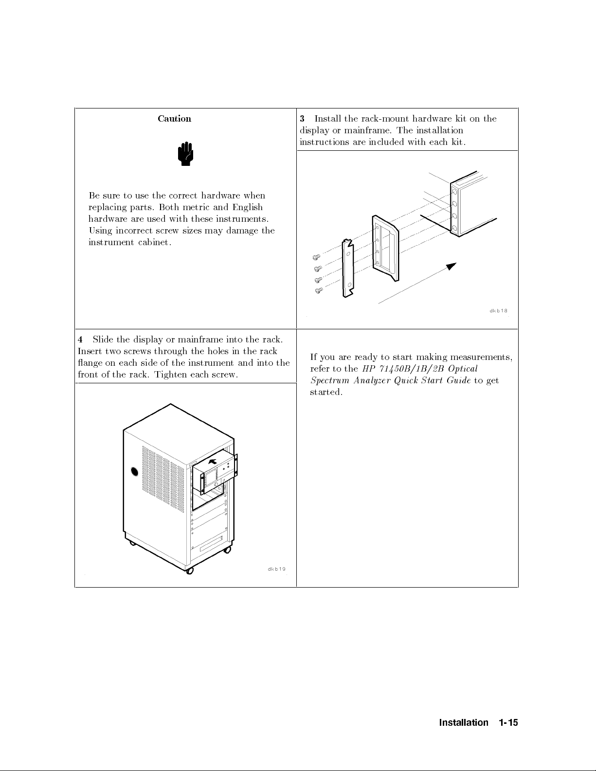
Caution
Be sure to use the correct hardware when
replacing parts. Both metric and English
hardware are used with these instruments.
Using incorrect screw sizes may damage the
instrument cabinet.
the
to
holes
h
in
screw.
in
t
the
and
Slide
4
Insert
ange
t
fron
of
t
on
w
the
the
screws
o
eac
displa
side
h
rac
through
Tigh
k.
or
y
the
of
ten
mainframe
the
instrumen
eac
in
rac
rac
to
3
Install the rack-mount hardware kit on the
display or mainframe. The installation
instructions are included with eachkit.
k.
k
the
y
If
refer
e
Sp
are
ou
to
ctrum
the
A
ready
HP
nalyzer
start
to
71450B/1B/2B
Quick
started.
making
Start
measuremen
al
Optic
to
Guide
ts,
get
Installation
1-15
Page 32
Optional: Connecting the Optical Spectrum Analyzer System
to Another Display or Mainframe
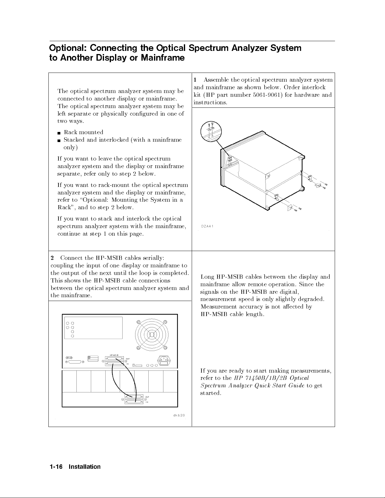
1
Assemble the optical spectrum analyzer system
The optical spectrum analyzer system maybe
connected to another display or mainframe.
The optical spectrum analyzer system maybe
and mainframe as shown below. Order interlock
kit (HP part number 5061-9061) for hardware and
instructions.
left separate or physically congured in one of
twoways.
Rack mounted
Stacked and interlocked (with a mainframe
only)
If you want to leave the optical spectrum
analyzer system and the display or mainframe
separate, refer only to step 2 b elow.
If you want to rack-mount the optical spectrum
mainframe,
or
y
displa
the
step
to
stac
to
t
analyzer
step
and
1
k
on
Moun
elo
b
2
and
system
this
ting
w.
terlo
in
with
page.
the
k
c
the
System
optical
the
mainframe,
in
a
analyzer
to \Optional:
refer
k",
Rac
ou
y
If
ectrum
sp
ue
tin
con
w
and
an
system
at
Connect
2
coupling
output
the
sho
This
ween
bet
mainframe.
the
the HP-MSIB
input of
the
of the
ws the
HP-MSIB cable
the optical
one
next un
spectrum
cables
displa
the
til
serially:
mainframe
or
y
is
op
lo
connections
analyzer
to
completed.
system
and
displa
the
een
is
only
etw
operation.
are digital,
tly
sligh
Since
degraded.
HP-MSIB
Long
mainframe
signals on
the HP-MSIB
measuremen
w remote
allo
sp
t
cables b
eed
Measurement accuracy is not aected by
HP-MSIB cable length.
ou are ready to start making measuremen
If y
refer to the
Spectrum A
HP 71450B/1B/2B Optic
nalyzer Quick Start Guide
al
to get
started.
y
the
and
ts,
1-16
Installation
Page 33
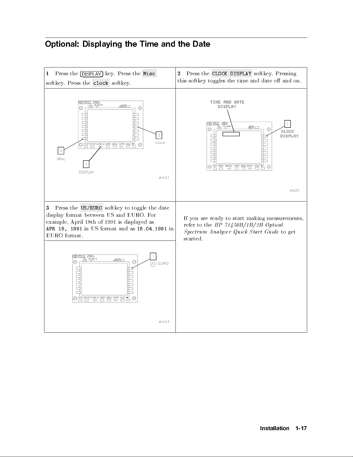
Optional: Displaying the Time and the Date
1
Press the
4
DISPLAY
softkey. Press the
N
N
N
N
N
N
the
Press
3
display
example, April
18,
APR
O
EUR
format
1991
format.
US/EURO
b
18th
in
NN
N
N
N
N
et
US
5
key. Press the
NNNNNNNNNNNNNNN
N
clock
N
N
N
N
N
N
N
NN
softk
US
een
w
1991
of
format
softkey.
to
ey
and
displa
is
and
NNNNNNNNNNNN
N
Misc
toggle
O.
EUR
ed
y
18.04.1991
as
the
F
as
or
date
NNNNNNNNNNNNNNNNNNNNNNNNNNNNNNNNNNNN
2
Press the
N
CLOCK DISPLAY
softkey. Pressing
this softkey toggles the time and date o and on.
measuremen
al
Optic
Guide
in
y
If
refer
e
Sp
are
ou
to
ctrum
the
A
to
ready
71450B/1B/2B
HP
nalyzer
start
Quick
making
Start
started.
to
ts,
get
Installation
1-17
Page 34
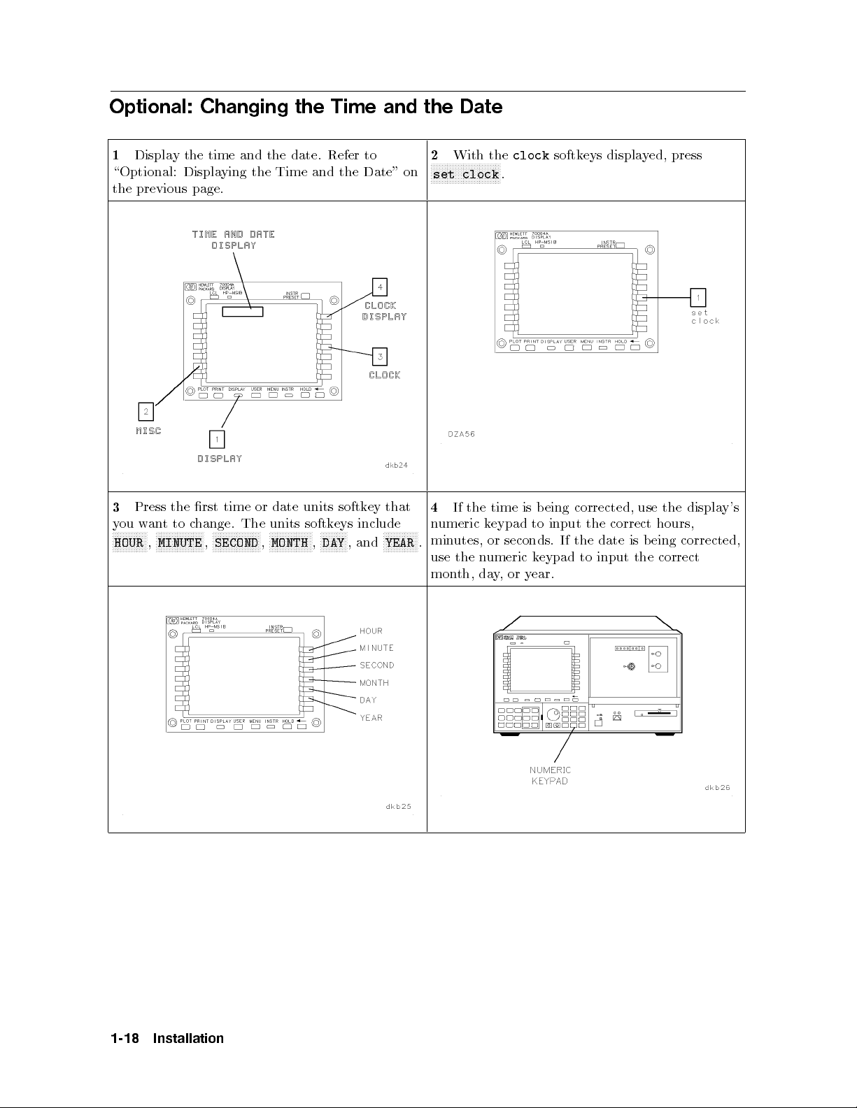
Optional: Changing the Time and the Date
1
Display the time and the date. Refer to
\Optional: Displaying the Time and the Date" on
2
With the
NNNNNNNNNNNNNNNNNNNNNNNNNN
set clock
the previous page.
that
ey
softk
units
date
or
time
rst
the
Press
3
ou
y
N
N
N
N
N
N
N
HOUR
N
N
N
an
w
N
NN
,
to
t
NN
N
N
N
N
N
N
N
N
N
N
MINUTE
hange.
c
N
N
N
N
N
N
,
The
NN
N
N
N
N
N
N
N
N
N
N
SECOND
4
units
N
N
N
N
N
N
,
N
N
N
N
N
N
N
N
N
MONTH
N
N
N
N
NN
N
N
N
N
N
N
N
N
N
N
N
,
,
DAY
and
N
N
N
N
N
N
YEAR
umeric
n
N
NN
N
N
N
N
min
.
include
eys
softk
use
mon
the
If
utes,
the
th,
time
eypad
k
or
umeric
n
da
clock
.
seconds.
or
,
y
softkeys displayed, press
corrected,
eing
b
is
correct
the
input
to
is
date
the
If
input
to
eypad
k
ear.
y
use
the
hours,
eing
b
correct
displa
the
corrected,
y's
1-18
Installation
Page 35
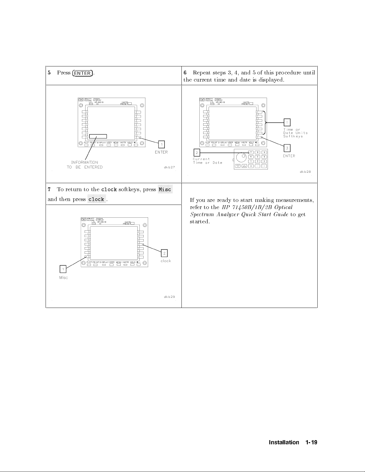
5
7
and
Press
return
To
then
4
ENTER
press
to
NN
N
clock
5
the
NN
.
N
N
N
N
N
N
N
clock
N
N
N
N
.
softk
eys,
press
N
N
N
N
N
N
Misc
6
Repeat steps 3, 4, and 5 of this pro cedure until
the current time and date is displayed.
N
N
N
N
N
N
N
to
ts,
get
y
If
refer
e
Sp
are
ou
to
ctrum
the
A
to
ready
71450B/1B/2B
HP
nalyzer
start
Quick
making
Start
measuremen
al
Optic
Guide
started.
Installation
1-19
Page 36

Page 37

2
If You Have a Problem During Installation
Introduction
This chapter will help you correct problems you may encounter during installation of the
optical spectrum analyzer. The problem or symptom is listed at the top of each page. Most
problems have a brief description or explanation, followed byachecklist of items that could
be causing the problem. Using the checklist of possible solutions will help you correct the
problem. If the problem is internal to the optical spectrum analyzer, the checklist will also
help to identify the faulty module, display, or mainframe.
Refer to \What to Expect When You Turn on the Optical Spectrum Analyzer" in this chapter
information
for
regarding
the
normal
steps
that
ccur
o
when
instrumen
the
turned
rst
is
t
on.
Problems Requiring
ternal
in
are
Problems
hnical
tec
mainframe
or
returning
Returned
that
information.
return
or
instrumen
the
for Service".
Refer
the
are
t
Additional T
a
dule,
mo
a
to
service
the
to
to
vided
t
in
\If the
instrumen
pro
echnical
,
y
displa
cumen
do
Hewlett-P
Optical
a
or
tation
ac
k
Resources
mainframe
fault
the
for
servicing.
for
ard
ectrum
Sp
require
will
mo
y
Analyzer
additional
displa
dule,
Instructions
Needs
to
for
b
,
y
e
Problem
a
e
v
Ha
ou
Y
If
During
Installation
2-1
Page 38

What to Expect When You Turn on the Optical Spectrum Analyzer
Each time the optical sp ectrum analyzer is turned on, the following actions take place:
1. The module self-test pro cedure turns on all the LEDs, except the STATUS LEDs. The
STATUS LEDs will turn on one second later. Refer to Figure 2-1.
This description identies the optical spectrum analyzer mo dule LEDs that light.
Depending on the display or mainframe used, their LEDs will also light during turn on.
2. After the preliminary self-test, all optical spectrum analyzer mo dule front-panel LEDs are
turned o.
3. The display's model number is briey displayed on screen.
4. The system begins running an instrument INITIALIZING routine.
5. At the b eginning of the INITIALIZING routine, the ACT LED lights and remains lit.
6. At the end of the INITIALIZING routine, the MEASURE LED lights as the optical
spectrum analyzer sweeps across the display. If the mo dule is an HP 70951B, the
MONOCHROMATOR INPUT LED will also light.
2-2
Figure 2-1.
Optical Spectrum Analyzer Front Panel
wn)
71451B
(HP
Problem
a
e
v
Ha
ou
Y
If
During
Installation
Sho
Page 39
If the Optical Spectrum Analyzer Will Not Turn On
Pressing the LINE switch on the front panel of each display and mainframe in system should
turn the system on. If there is a problem providing power to the system, these symptoms will
occur:
The display will remain blank.
The LINE LED on the front panel of the display or mainframe will not light.
The actions describ ed in \What to Expect When You Turn on the Optical Spectrum
Analyzer" will not occur.
If you press the LINE switch on the front panel of the display or the mainframe and the
optical spectrum analyzer does not turn on, check the follo wing items:
Check that the optical spectrum analyzer is connected to the ac p ower source.
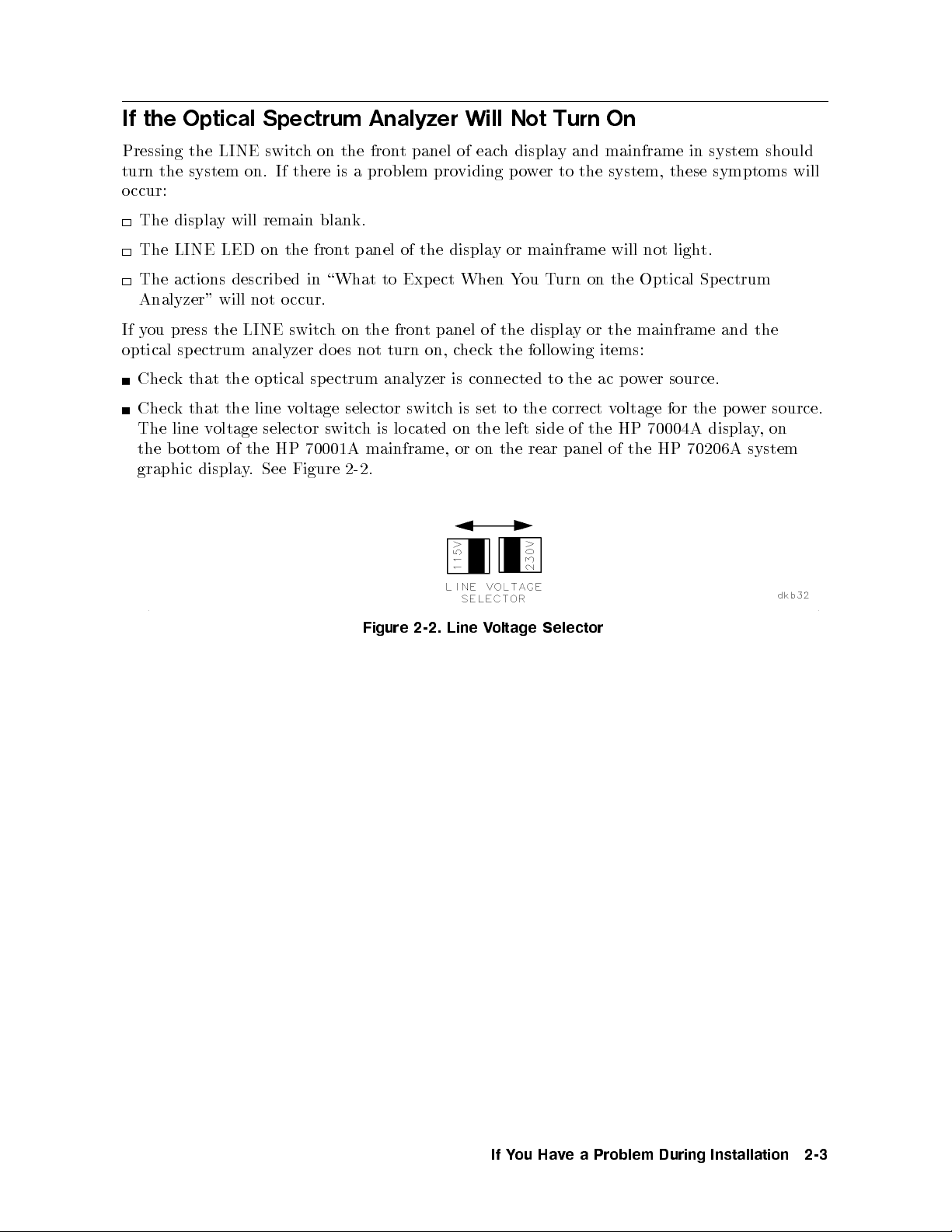
Check that the line voltage selector switch is set to the correct voltage for the power source.
The line voltage selector switch is located on the left side of the HP 70004A display,on
the bottom of the HP 70001A mainframe, or on the rear panel of the HP 70206A system
graphic
displa
Figure
See
.
y
2-2.
Figure
2-2.
Line
oltage
V
Selector
Problem
a
e
v
Ha
ou
Y
If
During
Installation
2-3
Page 40
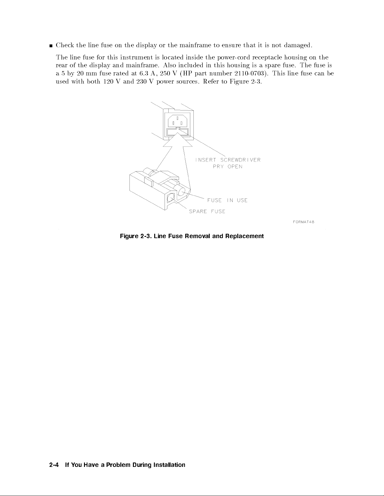
Check the line fuse on the display or the mainframe to ensure that it is not damaged.
The line fuse for this instrument is lo cated inside the power-cord receptacle housing on the
rear of the display and mainframe. Also included in this housing is a spare fuse. The fuse is
a5by 20 mm fuse rated at 6.3 A, 250 V (HP part number 2110-0703). This line fuse can be
used with both 120 V and 230 V p ower sources. Refer to Figure 2-3.
Figure
2-3.
Line
Fuse
Remo
Replacement
and
al
v
2-4
Problem
a
e
v
Ha
ou
Y
If
During
Installation
Page 41
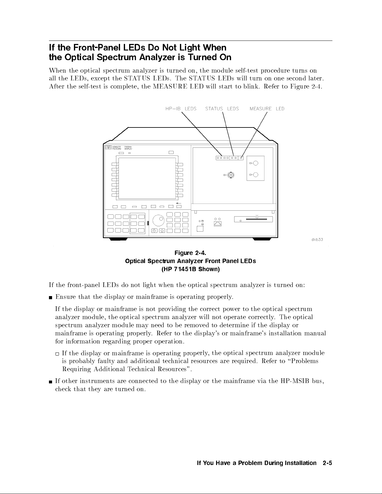
If the Front-Panel LEDs Do Not Light When
the Optical Spectrum Analyzer is Turned On
When the optical spectrum analyzer is turned on, the mo dule self-test procedure turns on
all the LEDs, except the STATUS LEDs. The STATUS LEDs will turn on one second later.
After the self-test is complete, the MEASURE LED will start to blink. Refer to Figure 2-4.
2-4.
Analyzer
optical
erating
op
Front
wn)
sp
prop
anel
P
ectrum
.
erly
LEDs
analyzer
turned
is
on:
the fron
If
Ensure
t-panel LEDs
displa
the
that
Optical
do not
or
y
Spectrum
(HP
when
t
ligh
mainframe
Figure
71451B Sho
the
is
If the display or mainframe is not providing the correct power to the optical sp ectrum
analyzer module, the optical sp ectrum analyzer will not operate correctly. The optical
spectrum analyzer mo dule may need to be removed to determine if the displayor
mainframe is operating prop erly. Refer to the display's or mainframe's installation manual
eration.
op
information
for
the
If
displa
regarding prop
mainframe
or
y
is probably faulty and additional tec
Requiring Additional T
If other instrumen
ts are connected to the displa
er
operating
is
prop
hnical resources are required. Refer to \Problems
echnical Resources".
erly
,
the
optical
ectrum
sp
analyzer
mo
y or the mainframe via the HP-MSIB bus,
check that they are turned on.
dule
Problem
a
e
v
Ha
ou
Y
If
During
Installation
2-5
Page 42

If the Optical Spectrum Analyzer Front-Panel ERR LED
Remains Lit or Blinks after the Self-Test
The ERR LED is one of the twoSTATUS LEDs on the front panel of the optical spectrum
analyzer module. The ERR LED should light during the optical spectrum analyzer's self-test.
It is turned on and o so quickly during the self-test that you may not be able to see it light.
Refer to Figure 2-5.
After the self-test, the ERR LED lights when an error (problem) is encountered. When it
lights, it will either remain on continuously or it will blink.
Figure 2-5.
Information
Optical
Spectrum
Analyzer
Error
(HP 71451B Shown)
If the ERR LED remains on continuously, it is indicating that there may b e a problem with
the optical spectrum analyzer. Perform the following steps:
Press
Press
k the displa
4
DISPLA
N
N
N
N
N
N
N
N
N
N
NN
N
REPORT
or
4
5
Y
DSP
NN
N
N
N
N
N
N
N
N
N
N
N
NN
N
N
N
N
N
N
N
N
N
N
NN
N
ERRORS
y for the rep orted
.
5
.
error.
1.
2.
3. Chec
4. Refer to \If Errors Are Reported on the Display" for help correcting the error.
If the ERR LED blinks,
it is indicating that there ma
y be a problem with the HP-MSIB.
Check the following items:
If more than one mainframe is connected together, check that all HP-MSIB cables are
op.
lo
a
form
securely connected
whether
k
Chec
Chec
3.
\Step
to
v
Ha
ou
Y
If
2-6
e
there
a
and
are
System's
the
k
Problem
ensure
o
w
t
During
that
dules
mo
HP-MSIB
Installation
they
are
the
in
Addresses."
connected
system
with
serially
in
to
same
the
Chapter
HP-MSIB
for instructions.
1
address.
Refer
Page 43
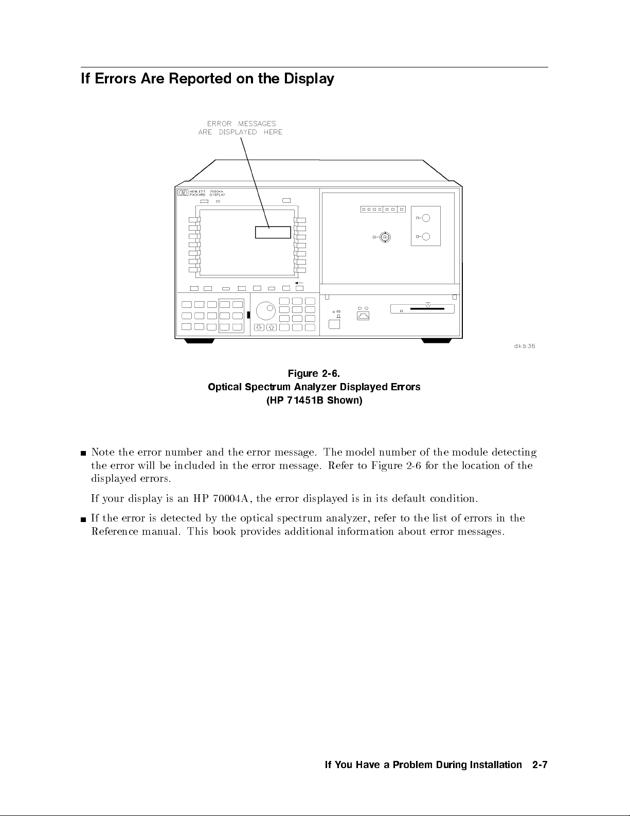
If Errors Are Reported on the Display
2-6.
Analyzer
Sho
The mo
Refer
displa
Displa
ed
y
wn)
is
del
to
in
Errors
ed
y
um
n
Figure
its
er
b
2-6
default
the
of
the
for
condition.
mo
dule
cation
lo
detecting
of
Note
error
the
displa
your
If
the
ed
y
displa
error
will b
errors.
y
er
b
um
n
e included
HP
an
is
Optical
the
and
in
70004A,
Spectrum
(HP
error message.
message.
error
the
error
the
Figure
71451B
If the error is detected by the optical spectrum analyzer, refer to the list of errors in the
Reference manual. This b ook provides additional information about error messages.
the
Problem
a
e
v
Ha
ou
Y
If
During
Installation
2-7
Page 44

If the Optical Spectrum Analyzer Front-Panel HP-IB LEDs
Remain Lit after the Self-Test
The HP-IB LEDs on the front panel of the optical sp ectrum analyzer are turned on then o,
one at a time, during the optical sp ectrum analyzer's self-test. The four HP-IB LEDs are:
service request (SRQ), talk (TLK), listen (LSN), and remote (RMT). Refer to Figure 2-7 for
the location of each of the HP-IB LEDs. The HP-IB LEDs reveal the status of the optical
spectrum analyzer module when it is b eing controlled by a computer.
Optical
Figure
Spectrum
71451B
(HP
2-7.
Analyzer
Sho
HP-IB
wn)
LEDs
2-8
Problem
a
e
v
Ha
ou
Y
If
During
Installation
Page 45

The follo wing lists and describes the HP-IB LEDs, and suggests what to checkif anLED
remains on after the self-test.
LED Solution
SRQ The service request (SRQ) LED lights when the optical spectrum analyzer has
requested computer service. Check for error messages on the display.
TLK
LSN
RMT
The talk (TLK) and listen (LSN) LEDs light when a controller has addressed the
optical spectrum analyzer to talk or listen over the HP-IB. The remote (RMT) LED
lights if the remote enable (REN) line is asserted and the optical sp ectrum analyzer
is addressed byacontroller.
If the TLK, LSN, or RMT LEDs remain on after the self-test:
Check that no HP-IB address conicts with other equipment on the HP-IB bus.
Two instruments on the HP-IB bus that have the same HP-IB address will cause an error.
Remove the HP-IB bus from the optical sp ectrum analyzer.
If the LED turns o, the problem is probably caused by the controller or another
ectrum
source
the
on,
then
see
the
on,
bus.
analyzer
the
of
optical
on.
k
bac
the problem
if
optical
are
to the
HP-IB bus.
problem.
ectrum
sp
analyzer
remains.
ectrum analyzer
sp
required.
Refer
Remov
probably
dule
mo
\Problems
to
e other
the
is
probably
is
Requiring
instrumen
cause.
fault
Additional
y
ts
and
instrument
bus to
the
urn
T
Chec
the
If
the
LED
the
the
k
LED
Return
the
If
additional
hnical
ec
T
HP-IB
the
on
optical
sp
isolate the
remains
o,
er
w
o
p
to
LED
still
is
hnical resources
tec
Resources".
from
Problem
a
e
v
Ha
ou
Y
If
During
Installation
2-9
Page 46

If the Display HP-MSIB or the Mainframe I/O CHECK Indicator Light
Remains Lit
The display HP-MSIB fault indicator light and the mainframe I/O CHECK status indicator
light indicate the status of the HP-MSIB. If either of the lights are on, there is a problem with
the HP-MSIB. Refer to Figure 2-8 for the lo cation of the HP-MSIB indicator light on the
display and the lo cation of the I/O CHECK indicator light on the mainframe.
Verify that the power to all mainframes and stand-alone display instruments is on.
Check that all HP-MSIB cables are securely connected and ensure that they are connected
serially to form a lo op.
Checkfortwo mo dules in the system with the same HP-MSIB address. Refer to \Step 3.
Check the System's HP-MSIB Addresses." in Chapter 1 for instructions.
Check for a faulty mainframe or stand-alone displayby removing all of the HP-MSIB cables
and noting the state of the indicator light as each cable is removed.
If the indicator light is still on, that mainframe, display, or one of its mo dules is probably
causing
If
the
the indicator
HP-MSIB
ligh
problem.
es
go
t
out,
the
problem
probably
is
with
some
other
part
of
the
system.
mainframes
and
ys
displa
all
If
op
satisfactorily b
erate
y themselv
es,
HP-MSIB
the
k
hec
c
cables.
2-10
Figure
Problem
a
e
v
Ha
ou
Y
If
2-8. HP-MSIB and I/O CHECK Indicator Lights
During
Installation
Page 47

If the Mainframe CURRENT Indicator Light Remains Lit
The CURRENT error indicator light turns on when the mainframe power supply senses a
currentoverload. Refer to Figure 2-9 for the lo cation of the CURRENT indicator light.
Check to see which module is causing the currentoverloading condition.
Turn the power o.
Remove one module from the mainframe.
Turn the power on.
If the indicator light is o, the optical spectrum analyzer module is probably faulty and
additional technical resources are required. Refer to \Problems Requiring Additional
Technical Resources".
If the indicator light is still on, continue removing modules, one at a time, until
the module causing the indicator light is identied. If removing a mo dule causes
the indicator light to turn o, refer to the service manual for that module for help
correcting the problem.
the indicator
If
probably
fault
y
light
Refer
.
dules
mo
all
after
the
on
HP
70001A
Mainfr
ame
remains
to
Figure 2-9. Current Indicator Light
ha
b
e
v
Servic
een
remo
Manual
e
mainframe
the
ed,
v
assistance.
for
is
Problem
a
e
v
Ha
ou
Y
If
During
Installation
2-11
Page 48
If the Optical Spectrum Analyzer Needs to be Returned for Service
When an instrument is returned to a Hewlett-Packard service oce for servicing, it must be
adequately packaged and have a complete description of the failure symptoms attached.
When describing the failure, please be as specic as possible about the nature of the problem.
Include copies of additional failure information (such as instrument failure settings, data
related to instrument failure, and error messages) along with the instrument being returned.
Please notify the service oce before returning your instrument for service. Any sp ecial
arrangements for the instrument can be discussed at this time. This will help the HP service
oce repair and return your instrument as quickly as possible.
Repackaging an instrument requires original shipping containers and materials or their
equivalents. Hewlett-Packard oces can provide packaging materials identical to the original
materials.
Caution
Packaging materials not specied can result in instrument damage. Never
use styrene pellets to package electronic instruments. The pellets do not
adequately cushion the instrument, do not prevent all instrumentmovement,
at
of
y
k
equiv
54 kg
strength.
.
end
the
noted
y
an
instrumen
the
alen
reduce
to
(120 lb),
ts
of
are
The
this
error
b
the
use
cedure),
pro
messages or
the
in
t
w
ho
est;
ossibilit
p
double-w
a
carton
factory
er,
ev
yof
ust
m
place
and
other
k
pac
follo
the
ESD damage.
corrugated
alled,
oth
b
e
b
return
o
T
out
Fill
1.
b
the
erformance
p
help prev
o
T
2.
materials.
instructions
W
a.
F
b.
cardb
the
the
with
x
o
the
rap
instrumen
or
oard carton
and can
instrument
Service
instrumen
the
data.
damage
t
en
Original
in
result
instrumen
that
ts
generate static
service
for
orm
Repair
F
t.
Send
during
shipping
materials
acceptable
ti-static
an
in
t
weigh
of 159
less than
kg (350
electricity
cated
(lo
cop
a
transit,
aging.
k
pac
lb)
pac
or
plastic
test
enough and strong enough to accommo date the instrument. Allow at least three to four
inches on all sides of the instrument for packing material.
c. Surround the equipment with three to four inches of packing material to protect the
module and to preventmovement in the carton. If packing foam is not available,
TM
Cap
alternativ
est
the b
ti-static
an
94545.
California
pink
provide sucien
S.D.-240
is
e
Cap
Air
Cap.
Air
t protection
Air
plastic sheeting
is
rapping
W
and also prev
with
sev
t
Air
1-1/4
eral times
instrumen
the
from Sealed
lled
entmovement in the carton.
Corp
inc
oration,
bubbles.
air
h
this
in
yw
Ha
material
it
helpful
aging
wing
large
ard,
Use
in
should
3. Seal the carton with strong n
4. Mark the carton FRA
GILE, HANDLE
ylon adhesiv
5. Retain copies of all shipping papers.
2-12
Problem
a
e
v
Ha
ou
Y
If
During
Installation
e tap e.
WITH CARE.
Page 49

Item HP
1 9211-6708 5 1 Carton
2 9220-4945 7 1 Foam End Cap (Set of 2)
P
CD Qt
y
Description
er
b
Num
art
e
v
ad
Problem
a
During
3 9220-4946 8 1 Bottom P
Figure 2-10. Packaging Materials for HP 70950B/1B/2B Modules
Ha
ou
Y
If
Installation
2-13
Page 50
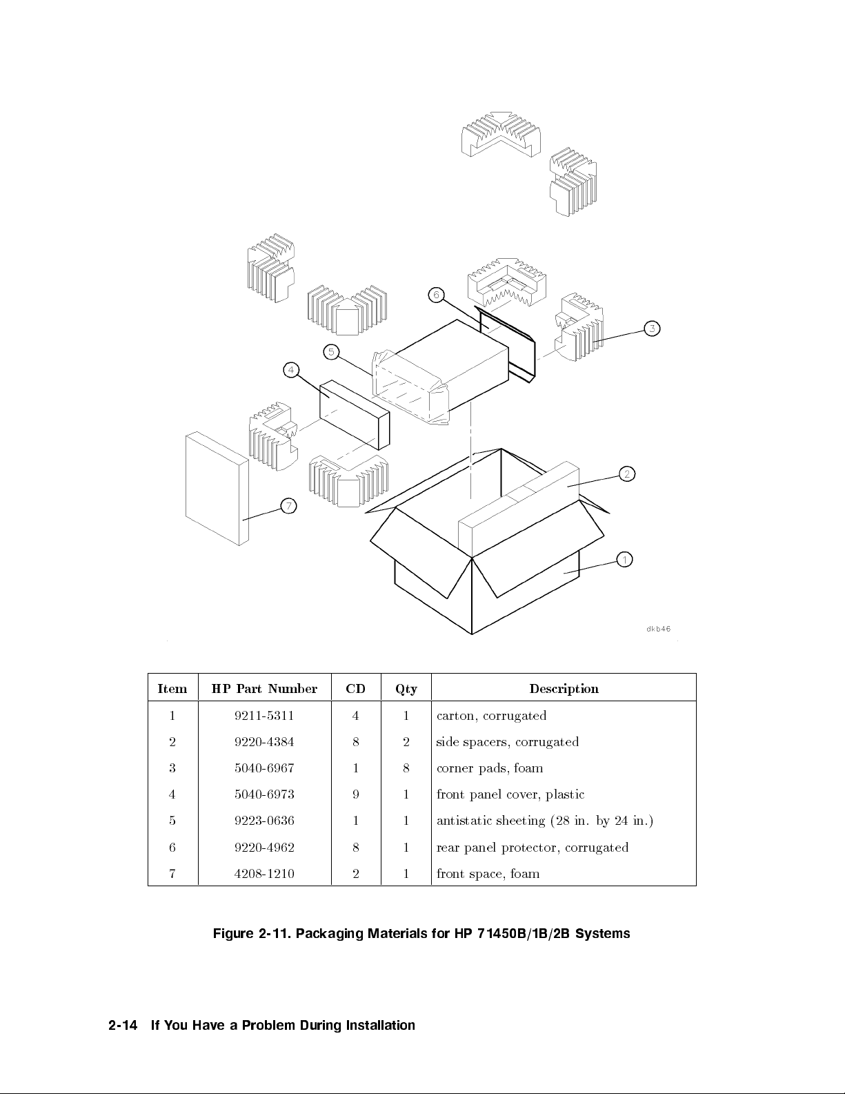
Item HP Part Number CD Qty Description
1 9211-5311 4 1 carton, corrugated
2 9220-4384 8 2 side spacers, corrugated
foam
panel
t
pads,
co
v
er,
plastic
3 5040-6967 1 8 corner
4 5040-6973 9 1 fron
5 9223-0636 1 1 antistatic sheeting (28 in. b
6 9220-4962 8 1 rear panel protector, corrugated
7 4208-1210 2 1 front space, foam
24 in.)
y
2-14
Figure
e
v
Ha
ou
Y
If
2-11. P
Problem
a
ackaging
During
Materials
Installation
for
71450B/1B/2B
HP
Systems
Page 51

Date:
Company:
Address:
Technical contact
person:
Phone:
Model number:
Serial number:
ber:
num
P.O.
Service Repair Form
Accessories
with
returned
unit:
Other:
Service Needed:
Other:
symptoms
ailure
F
part
is
unit
If
instruments:
and sp
system,
of
none
adapter(s)
calibration
calibration
ecial con
mo
list
cables(s)
only
trol settings:
er(s)
b
num
del
repair
of
wer
o
p
other
cable
in
repair
terconnected
and
Problem
a
e
v
Ha
ou
Y
If
During
Installation
2-15
Page 52

Sales and service offices
Hewlett-Packard has sales and service oces lo cated around the world to provide complete
support for Hewlett-Packard products. To obtain servicing information or to order
replacement parts, contact your nearest Hewlett-Packard sales and service oce. In any
correspondence or telephone conversation, refer to the instrumentby its mo del number, serial
number, and option designation.
2-16
Problem
a
e
v
Ha
ou
Y
If
During
Installation
Page 53

Hewlett-Packard Sales and Service Offices
U.S. FIELD OPERATIONS
Headquarters
Hewlett-Packard Company
19320 Pruneridge Avenue
Cupertino, CA 95014 U.S.A.
(800) 752-0900
Colorado
Hewlett-Packard Company
24 Inverness Place, East
Englewood, CO 80112
(303) 649-5000
New Jersey
Hewlett-Packard Company
120 West Century Road
Paramus, NJ 07653
(201) 586-5400
Headquarters
S.A.
ard
k
Route
Meyrin
ac
du
2/Genev
Nan
t-d'Avril
a
Hewlett-P
150,
1217
Switzerland
780.8111
22)
(41
California, Northern
Hewlett-Packard Company
301 East Evelyn
Mountain View, CA 94041
(415) 694-2000
Georgia
Hewlett-Packard Company
2000 South Park Place
Atlanta, GA 30339
(404) 955-1500
Texas
Hewlett-Packard Company
930 East Campbell Road
Richardson, TX 75081
(214) 231-6101
EUROPEAN
rance
F
Hewlett-P
Av
1
Zone
F-91947
rance
F
(33
FIELD OPERA
ac
Du
ue
en
D'Activite
Les
82
69
1)
ard
k
Canada
Ulis
60 60
rance
F
De
Cedex
TIONS
Courtab
California, Southern
Hewlett-Packard Company
1421 South Manhatten Ave.
Fullerton, CA 92631
(714) 999-6700
Illinois
Hewlett-Packard Company
5201 Tollview Drive
Rolling Meadows, IL 60008
(708) 342-2000
y
Bad
y
6172)
ac
ac
Hom
ard
k
ard
k
16-0
euf
o
German
Hewlett-P
Hewlett-P
61352
German
(+49
Gm
Strasse
burg
bH
Britain
Great
Hewlett-P
Eskdale
okingham,
W
k
ac
Road,
Ltd.
ard
Winnersh
Berkshire
R
riangle
T
G11
5DZ
Problem
a
e
v
Ha
ou
Y
If
During
Installation
2-17
Page 54

Hewlett-Packard Sales and Service Offices (continued)
INTERCON FIELD OPERATIONS
Headquarters
Hewlett-Packard Company
3495 Deer Creek Rd.
Palo Alto, California 94304-1316
(415) 857-5027
China
China Hewlett-Packard Company
38 Bei San Huan X1 Road
Shuang YuShu
Hai Dian District
Beijing, China
(86 1) 256-6888
Taiwan
an
aiw
T
or, H-P
u Hsing
aiw
T
712-0404
2)
kard
Building
North Road
an
Hewlett-Pac
8th Flo
337 F
ei,
aip
T
(886
Australia
Hewlett-Packard Australia Ltd.
31-41 Joseph Street
Blackburn, Victoria 3130
(61 3) 895-2895
Japan
Yokogawa-Hewlett-Packard Ltd.
1-27-15 Yabe, Sagamihara
Kanagawa 229, Japan
(81 427) 59-1311
Canada
Hewlett-Packard Ltd.
17500 South Service Road
Trans-Canada Highway
Kirkland, Quebec H9J 2X8
Canada
(514) 697-4232
Singapore
Hewlett-Packard Singap ore Ltd.
Pte. Ltd.
Alexandra P.O. Box87
singapore 9115
(65) 271-9444
2-18
Problem
a
e
v
Ha
ou
Y
If
During
Installation
Page 55
Installation Reference
Introduction
This chapter includes:
Part numbers and model numbers for cables, to ols, and supplies that will be useful when
installing the optical spectrum analyzer.
A table showing and describing ac power cables.
Information about serial number and option lab els.
Electrostatic discharge (ESD) information and accessories.
3
Installation
Reference
3-1
Page 56

Optical Spectrum Analyzer Accessories
The following tables show the available accessories that maybe useful when installing your
optical spectrum analyzer. Each accessory listed has a description and an HP mo del number
or part number.
HP-MSIB Cables
HP-MSIB cables are used to interconnect mainframes and displays. For systems with
multiple mainframes and displays, the number of HP-MSIB cables required is the number of
mainframes and displays in the system.
HP Model Number Description
HP 70800A HP-MSIB cable, 0.5 m
HP 70800B HP-MSIB cable, 1.0 m
HP 70800C HP-MSIB cable, 2.0 m
HP 70800D HP-MSIB cable, 6.0 m
m
HP
70800E
HP-MSIB
cable,
30
Connector Interfaces
del
Mo
HP
81000AI
HP
81000FI
HP
HP 81000GI
81000KI
HP
81000SI
HP
81000VI
HP
Num
er
b
Description
Diamond
C/PC
F
D4
SC
DIN
HMS-10
connector
connector
connector
47256
connector
ST connector
connector
terface
in
terface
in
terface
in
interface
terface
in
terface
in
HP 81000WI Biconic connector interface
83410-20003 Diamond HMS-10 to HP universal adapter with panel mountange
5022-0991 Diamond HMS-10 to HP universal adapter
Memory
HP P
0950-1964 32
0950-2084 128 Kb
Cards
art Num
ber
Description
Kbyte RAM blank memory card (HP 85700A)
yte RAM blank memory card
5010-1594 HP 71451B/1B/2B, DFB, FP, and LED MeasurementPersonality
ROM Card
3-2
Installation
Reference
Page 57

Tools
HP Part Number Description
8710-1307 8 mm hex-ball driver, 6-1/2 inch shaft
8710-1651 8 mm hex-ball driver, 1-3/4 inch shaft
Miscellaneous Parts and Supplies
HP Part Number Description
2110-0703 Fuse, 6.3 A, 250 V
5061-9006 Panel-mainframe front blank, 1/8 module width
8500-2163 Display cleaner, thin-lm cleaner
85680-60093 Cable assembly, BNC (m) to SMB (f ), 1 meter, may be used to make
connections to the rear panel connectors
5086-7913 White light source lamp assembly replacement kit
kit
5086-6913 Exc
hange
white
ligh
source
t
lamp
assem
replacemen
bly
t
er
w
o
P
accordance
In
three-wire
receptacle,
suitable
A
additional
If
Cables
with
er
w
o
p
instrumen
the
for
cable
cables
ternational
in
cable.
systems
need
When
cabinet
t
b
to
this
shipp
ordered,
e
y standards,
safet
cable
grounded.
is
to
ed
connected
is
ternational
in
to
refer
T
able
instrumen
this
to
customers
3-1 for
a
prop
part n
is
t
erly
included
is
equipp
grounded
ers.
b
um
ed
p
with
with
w
o
eac
er
a
system.
h
Installation
Reference
3-3
Page 58
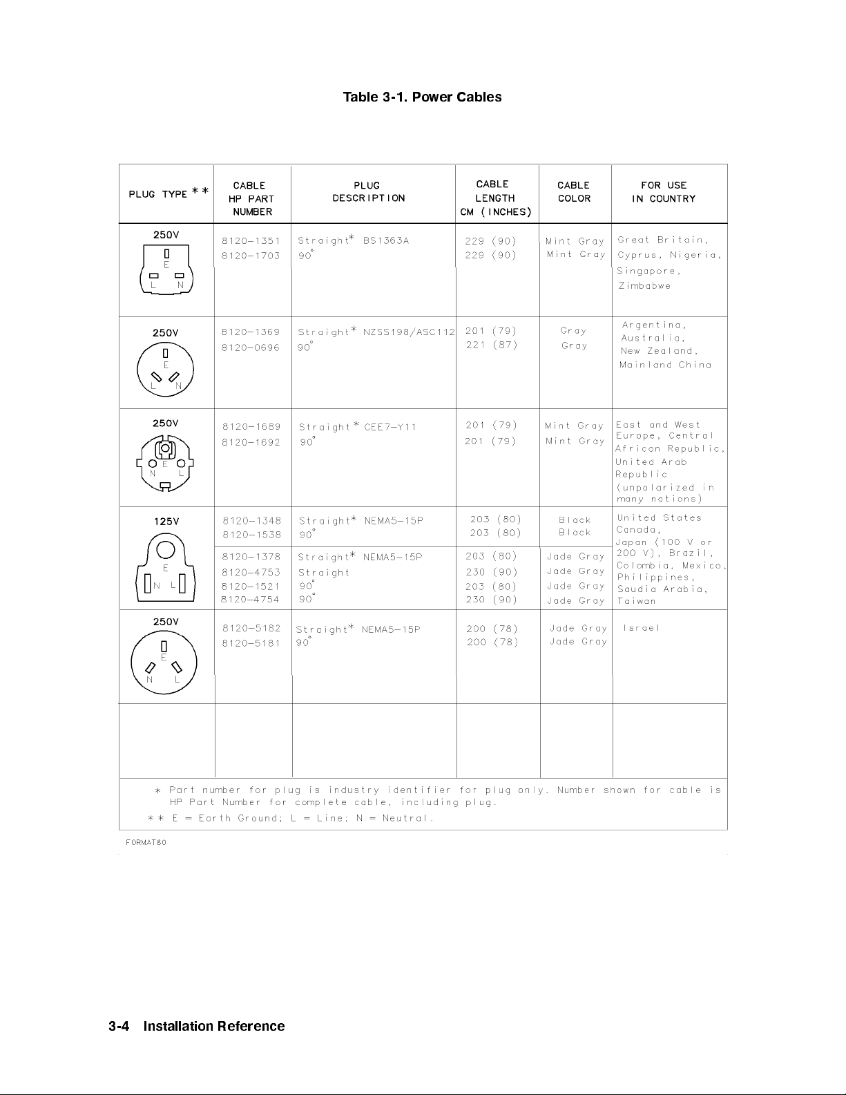
Table 3-1. Power Cables
3-4
Installation
Reference
Page 59
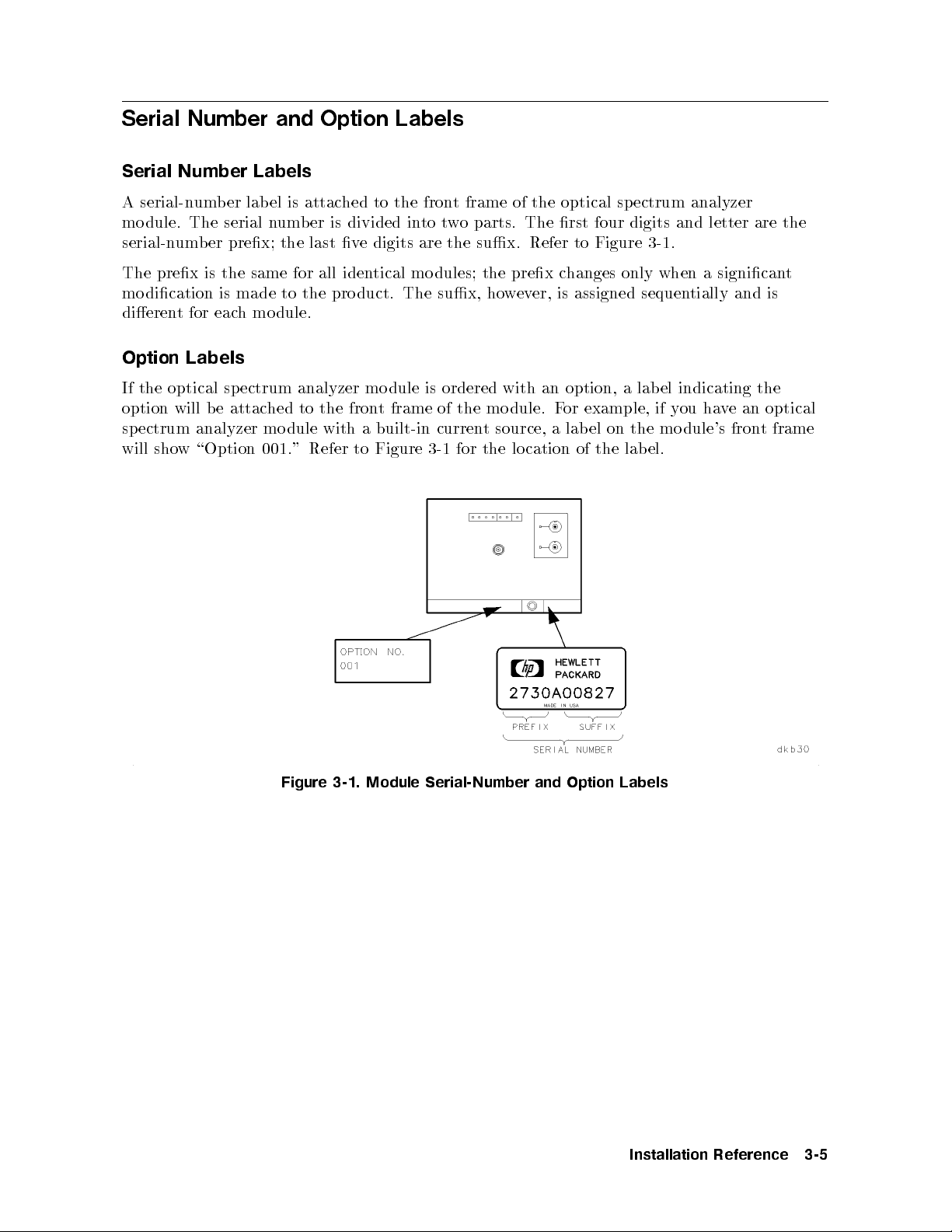
Serial Number and Option Labels
Serial Number Labels
A serial-number lab el is attached to the front frame of the optical spectrum analyzer
module. The serial number is divided into two parts. The rst four digits and letter are the
serial-number prex; the last ve digits are the sux. Refer to Figure 3-1.
The prex is the same for all identical mo dules; the prex changes only when a signicant
modication is made to the pro duct. The sux, however, is assigned sequentially and is
dierent for each module.
Option Labels
If the optical sp ectrum analyzer mo dule is ordered with an option, a lab el indicating the
option will be attached to the front frame of the mo dule. For example, if you have an optical
spectrum analyzer module with a built-in current source, a label on the module's front frame
will show \Option 001." Refer to Figure 3-1 for the lo cation of the lab el.
Figure 3-1. Module Serial-Number and Option Labels
Installation
Reference
3-5
Page 60

ESD Information
Electrostatic discharge (ESD) can damage or destroy electronic components. Therefore,
all work p erformed on assemblies consisting of electronic comp onents should be done at a
static-safe workstation.
Figure 3-2 shows an example of a static-safe workstation. Twotypes of ESD protection are
shown: the conductive table mat and wrist strap combination and the conductiveoormat
and heel strap combination. The twotypes
protection. Refer to Table 3-2 for a list of static-safe accessories and their part numbers.
must
be used together to ensure adequate ESD
3-6
Installation
Figure 3-2. Static-Safe Workstation
Reference
Page 61

Reducing ESD Damage
Below are suggestions that may help reduce the amount of ESD damage that o ccurs during
testing and servicing instruments.
PC Board Assemblies and Electronic Components
Handle these items at a static-safe workstation.
Store or transport these items in static-shielding containers.
Test Equipment
Before connecting any coaxial cable to an instrument connector for the rst time eachday,
momentarily
short the center and outer conductors of the cable together.
Personnel should be grounded with a resistor-isolated wrist strap b efore touching the center
pin of any connector and before removing any assembly from the instrument.
Be sure that all instruments are properly earth-grounded to prevent buildup of static
charge.
Static-Safe
HP
Num
the
Order
9300-0797 Set
Accessories
art
P
er
b
wing
follo
through
includes:
ground
ordered
e
b
able
T
Hewlett-P
y
an
3M
(The
wire.
separately.)
Static-Safe
3-2.
k
ac
con
static
wrist-strap
Sales and
ard
trol mat
Accessories
Description
Service
0.6 m
wrist-strap cord
and
Oce
and
ft)
4
2
ft
(2
m
1.2
2
are not
included.
9300-0980 Wrist-strap cord 1.5 m (5 ft)
9300-1383 Wrist-strap, color black, stainless steel, without cord, has four adjustable links
and a 7 mm post-type connection.
9300-1169 ESD heel-strap (reusable 6 to 12 months).
4.6
cm
They
(15
m
ft)
ust
Installation
Reference
3-7
Page 62

Page 63

4
Operation Verification Testing
Introduction
This chapter will help you install and perform the optical spectrum analyzer's operation
verication tests. It contains required and optional step-by-step instructions for running
the operation verication test software. The software is designed to provide a high level of
condence that the optical spectrum analyzer system meets its specications without requiring
excessive test equipment or test time.
Note
Before starting the operation verication tests, makebackup copies of the
operation verication test disks to ensure that your original disks will not be
cannot
replace
it
one
y
an
altered. If
ordered
e
b
the program
separately
.
data on
set
The
of
one
disks
disk
should
ust
m
e
b
ecome
b
ordered
altered,
to
disk.
the
of
l
al
e
v
ha
ust
m
ou
y
T
eration
op
mo
p
for
tests.
est
dels
v
tests,
Equipmen
erication
v
the
of
ma
ou
y
t,
erformance
DFB laser.
erication
t"
test
y
to
The
tests.
Chapter
in
soft
equipmen
to
e
v
ha
tested
e
b
1300
The
w
mo
nm
use
are
t. If
dify
using
5
as
w
y
DFB
the
of
ou
the
erform
p
o
T
equipment
test
equiv
the
or
designed
other
use
are.
w
soft
op
The
a
oth
b
laser is
nm
1550
of
all
listed
alen
supp
to
acceptable
eration
1300
v
nm
required to
laser
DFB
the op
in
equipmen
test
t
the
ort
mo
erication
laser
DFB
perform
optional
is
eration v
erication
\Recommended
The
t.
recommended
w
allo
1550 nm
a
eration
all
for
equipmen
dels
of test
tests
and
the op
Unless otherwise specied, optical connections should b e made with
9/125m patchcords using FC/PC connector interfaces. Clean all
connectors and optical input b ers before beginning the operation
verication tests.
Operation
erification
V
esting
T
4-1
Page 64
Manual versions of the wavelength accuracy test, the atness test, and the
dynamic range test are included; you may substitute these tests if you do
not have the specic equipment required to perform the automated versions
of these tests. Refer to Chapter 6 for these manual tests.
There are manual op erational checks, designed to verify the functionalit y of
the HP 70951B optical spectrum analyzer mo dule's additional instrument
modes, included at the end of Chapter 6. These instrument modes are not
veried by the test software.
The keys that are referred to in this chapter are for the HP 46021A
keyboard. Due to the various input devices (keyboard or mouse) supported,
some minor text dierences appear in the menus and softkeys displayed on
screen. Refer to \Computer Keyboard Compatibility and Mouse Op eration"
in Chapter 5 for information regarding your keyboard or mouse.
It takes ab out 1.5 hours to perform all of the automated operation
verication tests.
Chapter 6 describes each operation verication test in detail. Refer to that
hapter
c
information
for
regarding
individual
an
test.
4-2
Operation
erification
V
esting
T
Page 65

Step 1. Set up the Hardware for Operation Verification Testing
Operation verication software can run on HP 9000 Series 300 computers. The computer must
have:
A minimum of 2.5 to 4 megabytes of RAM (depending on the display conguration used).
An HP-IB interface.
A 3.5 inch double-sided exible disk drive.
A hard disk drive with 4 megabytes available space.
1. Connect the optical spectrum analyzer to the computer port.
There are two possible congurations:
If the computer has an HP 98624A HP-IB interface:
Connect your optical sp ectrum analyzer to the port labeled HP-IB SELECT CODE 8.
Check that the address switch on the HP 98624A HP-IB interface matches the HP-IB
controller device address.
lation
Instal
necessary
If
Guide,
the computer
If
olume
V
refer
,
1.
does
to
not
the
ha
HP
v
e
9000
an
HP
Series
98624A
200/300
HP-IB
Peripher
in
al
terface:
SELECT
using
ort
HP-IB
CODE
a
with
Connect
Connect
2.
CODE
Connect
3.
meter HP-IB
0.5
Occasionally
instruments.
terface.
in
7
the
p
the
ort.
optical
the
HP-IB
external
cable (HP
driv
disk
ou
y
If
sp
cables
disk
es exhibit
that
nd
ectrum
the
from
HP-IB
e's
driv
10833D,
unpredictable b
o
this
analyzer
equipmen
test
to the
similar
or
ccurs,
the
to
HP-IB
cable).
connect
eha
p
t
vior
the
ort
to
eled
lab
computer's
the
SELECT
when
driv
disk
HP-IB
CODE
sharing
a
to
e
SELECT
HP-IB
p
7
HP-IB
the
separate
4. Set the external test equipment and the optical sp ectrum analyzer line switches to ON.
Allow the equipmenttowarm up as specied for the op eration verication tests.
5. If the optical spectrum analyzer that you will b e testing is an Option 001, refer to
\Precision Resistor and RC Network" in Chapter 5 for instructions on constructing a
ectrum
precision resistor
analyzer's
urn the disk driv
6. T
curren
This
.
ork
w
net
C
R
and
source
t
option.
e and the computer on.
net
ork
w
is required
to
test
the
optical
sp
7.
Operation
erification
V
esting
T
4-3
Page 66
Step 2. Install the Software on an SRM or HFS Hard Disk
Note
For best results, install the op eration verication software on, and run the
tests from, a hard disk drive. If you want to run the tests from a exible disk
drive, see \Optional: Running the Operation Verication Tests from a Flexible
Disk Drive".
SRM is an acronym for shared resource manager; HFS is an acronym for hierarchical le
structure. This step is a general pro cedure for installing the op eration verication software
on an SRM or HFS hard disk system. For detailed information on creating directories and
copying les, refer to the appropriate SRM or HFS hard disk manuals.
Caution
Make backup copies of all write-protected disks. If the program data on an
individual disk should become altered, it cannot b e ordered separately.The
entire set of disks must be ordered to replace any one. Before making backup
copies of write-protected disks, initialize the backup disks:
For example:
":,700,0",2,3.
ust
m
ou
y
to
ecic
sp
erication
v
appropriate
use
your
ormat
F
system.
test
binary
Option
w
soft
les
3;
are,
loaded
terlea
in
er, the
wev
ho
ust
m
ou
y
the
to
in
MSVS
a
e
v
ha
computer.
and
BASIC
o load
T
and
programming
Note
factor
the
run
language
INITIALIZE
that
are
eration
op
and
e
v
BASIC
Load
1.
computer.
description of
CLOCK
COMPLEX
A
T
CR
5.13
necessary
If
eac
ual.
BASIC
HP
to an
refer
,
le.
h
reference
EDIT
ERR
GRAPH
man
KBD
MA
MS
to
in
elow
b
listed
les
BIN
the
with
later,
or
CRTB GRAPHX PDEV
CRTX HFS* SRM
CS80 HPIB TRANS
DCOMM
y
IO XREF
DISC
vironmen
*Optional:
y
Optional: required only for SRM
z
Optional: required only for DEBUG.
required
only
HFS
for
(hierarc
hical le
system)
(shared resource managemen
en
t) environment.
the
HP
Refer
T
z
y
z
t.
9000
to
Series
able
T
5-2
300
for
a
4-4
Operation
erification
V
esting
T
Page 67
2. Insert Disk 1 in the disk drive.
3. Assign the MSI (mass storage is) to the 3.5 inch double-sided exible disk drive and press
4
5
.
Return
For example, assigning MSI to a hard disk drive with an address of 700 would lo ok like
this:
MSI ":,700,0"
4. Type
LOAD "INSTALL",1
. Press
4
Return
5
.
5. The program will prompt you to enter the MSVS (mass storage volume sp ecier) of your
exible disk drive. Enter the address and press
4
Return
5
.
For example:
: ,700,1
6. The program will prompt you to enter the MSVS of your hard disk. Enter the address and
press
The
7.
op
program
the
Note
When
8.
If
displa
Keyb
4
RETURN
program
eration
display
prompted,
ha
ou
y
,
y
oard
5
.
will
erication
v
installed
Press
.
The
tains
con
HP
an
e
v
4
press
Esc
Compatibilit
prompt
another
in
4
RETURN
default
remo
46021A
4
5
System
test
these
ve
5
and
y
for
ou
y
program.
directory,
.
5
ws
sho
slashes.
1
Disk
eyb
k
ou
y
If
.
Mouse Op
directory
the
/OPV9000/OSA/
substitute that
leading and
insert
and
and
oard,
an
e
v
ha
eration" in
trailing
Disk
the
HP
where
path
is
slashes.
Press
2.
N
N
N
N
N
N
N
N
NN
NN
N
N
N
N
N
N
N
Continue
98203C
Chapter 5.
the
path for
N
N
N
N
Continue
N
N
N
N
N
N
N
softk
eyb
k
w
ou
y
default;
the default
sure
Be
NN
N
N
N
N
N
N
N
N
N
N
N
N
N
do
ey
refer to
oard,
N
an
N
N
install
to
t
you
if
our
y
N
N
N
N
the
tthe
wan
path
directory
sho
test
wn
path
on
.
the
on
ear
app
not
es
\Computer
Operation
erification
V
esting
T
4-5
Page 68
Step 3. Load the Software
To run the op eration verication test software, you must have a BASIC programming
language loaded into the computer. There are several binaries (BIN les) that must be loaded
also.
1. Make sure that BASIC 5.13 or later (with the appropriate BIN les listed in \Step 2.
Install the Software on an SRM or HFS Hard Disk") is loaded in the HP 9000 Series 300
computer. If necessary, refer to an HP BASIC reference manual.
2. Assign the MSI (mass storage is) to the directory path where the program is installed.
For example:
MSI "/OPV9000/OSA/"
3.
Type
LOAD "OPV",1
and press
4
Return
5
.
4. When the program prompts you to insert Disk 2, type
CONTINUE
and press
4
Return
5
.
4-6
Operation
erification
V
esting
T
Page 69
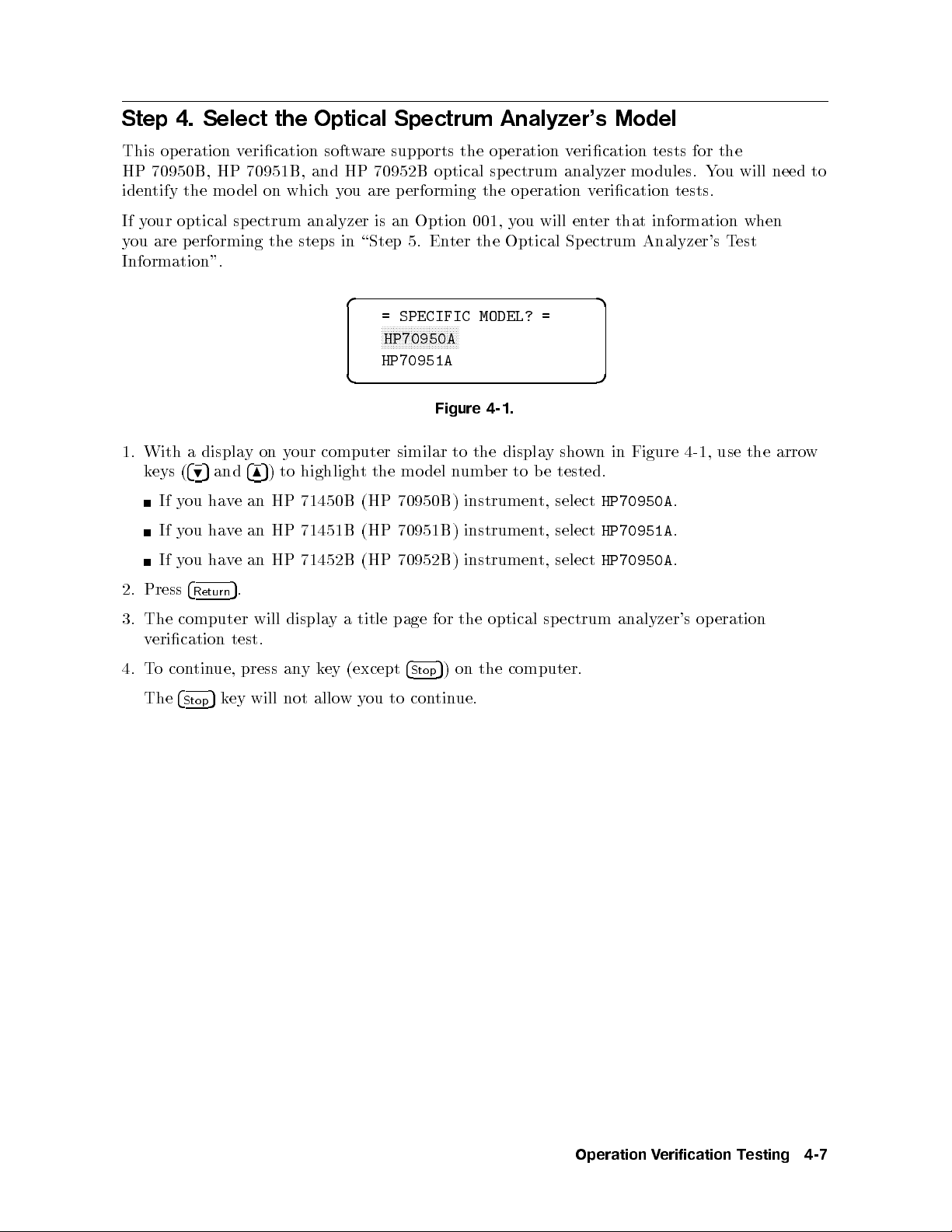
Step 4. Select the Optical Spectrum Analyzer's Model
This operation verication software supports the op eration verication tests for the
HP 70950B, HP 70951B, and HP 70952B optical spectrum analyzer modules. You will need to
identify the mo del on whichyou are performing the op eration verication tests.
If your optical sp ectrum analyzer is an Option 001, you will enter that information when
you are p erforming the steps in \Step 5. Enter the Optical Spectrum Analyzer's Test
Information".
d a
= SPECIFIC MODEL? =
NNNNNNNNNNNNNNNNNNNNNNNNNN
HP70950A
HP70951A
c b
Figure 4-1.
1. With a displayonyour computer similar to the display shown in Figure 4-1, use the arrow
tested.
e
b
to
er
b
um
n
del
keys
(
4
9
5
and
4
to highligh
5
)
8
t the
mo
Press
2.
The
3.
erication
v
o
T
4.
The
ou
y
If
ou
y
If
ou
y
If
4
Return
computer
tin
con
4
Stop
an
e
v
ha
an
e
v
ha
an HP
e
v
ha
.
5
test.
ue, press
will
ey
k
5
will
71450B
HP
71451B
HP
71452B (HP
displa
k
any
allo
not
ey
a
y
w
(HP
(HP
title
(except
ou
y
70950B)
70951B)
70952B)
page
4
Stop
con
to
for
5
tin
the
on
)
ue.
instrumen
instrumen
instrumen
optical
computer.
the
t,
t,
t,
sp
select
select
select
ectrum
HP70950A
HP70951A
HP70950A
analyzer's
.
.
.
eration
op
Operation
erification
V
esting
T
4-7
Page 70
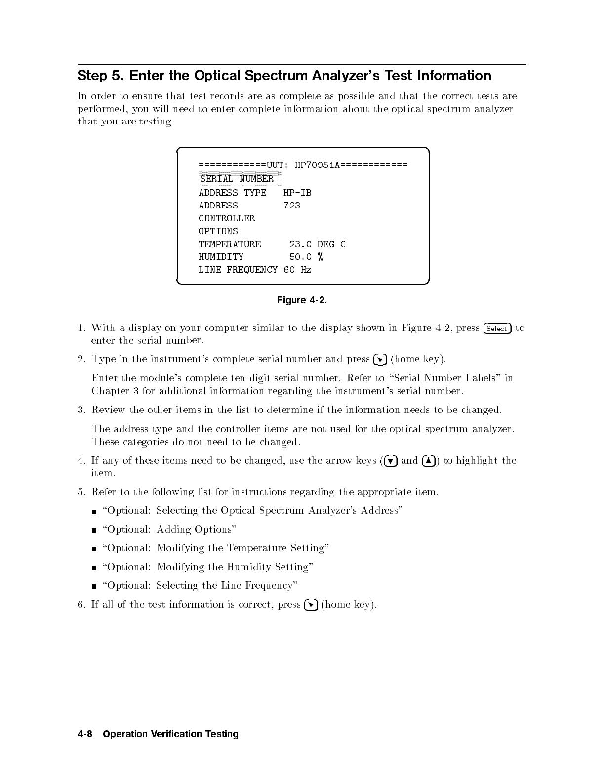
Step 5. Enter the Optical Spectrum Analyzer's Test Information
In order to ensure that test records are as complete as p ossible and that the correct tests are
performed, you will need to enter complete information about the optical spectrum analyzer
that you are testing.
d a
============UUT: HP70951A============
NNNNNNNNNNNNNNNNNNNNNNNNNNNNNNNNNNNNNNNNNNNN
SERIAL NUMBER
ADDRESS TYPE HP-IB
ADDRESS 723
CONTROLLER
OPTIONS
TEMPERATURE 23.0 DEG C
HUMIDITY 50.0 %
LINE FREQUENCY 60 Hz
c b
With
1.
en
T
2.
En
Chapter
Review
3.
The
These
If
4.
ter
yp
an
e
ter
address
yof
displa
a
serial
the
the
the
instrumen
mo
for
3
other
in the
categories
these items
y
on
y
um
n
dule's
additional
items
and
e
yp
t
do
computer
our
er.
b
complete
t's
complete
information
the
in
con
the
need
not
need to
Figure
similar
serial
ten-digit serial
regarding
determine
to
list
troller
to
be
items
hanged.
c
e
b
hanged,
c
to
n
use
um
are
the
b
n
the
4-2.
displa
er
um
the
if
not
y
press
and
Refer
er.
b
instrumen
information
the
used
w
arro
sho
for
k
eys
in Figure
wn
4
5
\Serial
to
t's
the
4
(
9
(home
serial
needs
optical
and
5
ey).
k
Num
um
n
sp
4
5
8
item.
5. Refer to the following list for instructions regarding the appropriate item.
\Optional: Selecting the Optical Spectrum Analyzer's Address"
\Optional: Adding Options"
emp
T
\Optional:
\Optional:
Mo
Mo
difying
difying
the
the
Humidit
\Optional: Selecting the Line F
erature
requency"
Setting"
y Setting"
4-2,
er
b
er.
b
e
b
to
ectrum
to
)
4
press
Lab
Select
els"
changed.
analyzer.
highlight
5
in
the
to
6. If all of the test information
esting
4-8
Operation
erification
V
T
is correct, press
4
5
(home k
ey).
Page 71
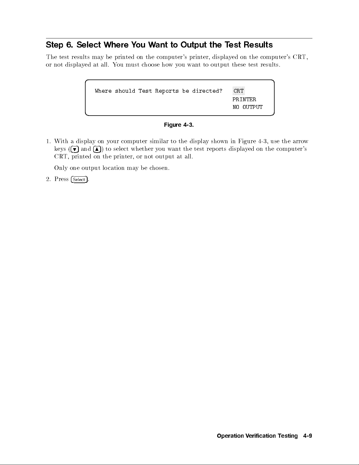
Step 6. Select Where You Want to Output the Test Results
The test results maybeprinted on the computer's printer, displayed on the computer's CRT,
or not displayed at all. You must choose howyou want to output these test results.
d a
Where should Test Reports be directed?
c b
Figure 4-3.
1. With a displayonyour computer similar to the display shown in Figure 4-3, use the arrow
keys (
495
and
485
) to select whether you want the test reports displayed on the computer's
CRT, printed on the printer, or not output at all.
Only one output lo cation maybechosen.
NNNNNNNNNNN
CRT
PRINTER
NO OUTPUT
2. Press
4
Select
5
.
Operation
erification
V
esting
T
4-9
Page 72
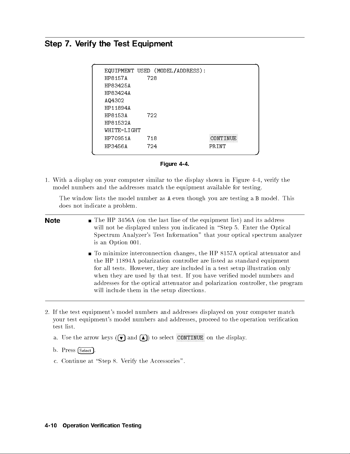
Step 7. Verify the Test Equipment
d a
EQUIPMENT USED (MODEL/ADDRESS):
HP8157A 728
HP83425A
HP83424A
AQ4302
HP11894A
HP8153A 722
HP81532A
WHITE-LIGHT
HP70951A 718
HP3456A 724 PRINT
c b
Figure 4-4.
er
to
hthe
A
as
1.
With
del
mo
The
do
a
es
displa
um
n
windo
not
on
y
and
ers
b
lists the
w
indicate
computer
our
y
addresses matc
the
model
problem.
a
n
um
similar
b
displa
the
equipment
though
en
ev
NNNNNNNNNNNNNNNNNNNNNNNNNN
CONTINUE
wn in
sho
y
ailable
av
ou
y
are
testing
Figure 4-4
testing.
for
a
B
,v
mo
erify the
This
del.
Note
test
the
If
2.
test
our
y
list.
test
a. Use the arro
b.
Press
c. Con
tin
address
its
and
list)
\Step
in
y
listed
test
a
ev
t
optical
our
8157A
as
setup
eried
the
ter
En
5.
ectrum
sp
optical
atten
standard
illustration only
n
del
mo
equipmen
um
HP
The
not b
will
ectrum
Sp
an
is
minimize
o
T
the HP
all
for
when
3456A
e
Analyzer's
Option
11894A
tests.
they
(on
ed
y
displa
001.
terconnection
in
olarization
p
ev
w
Ho
used
are
the
unless
T
er,
y
b
line
last
ou
y
Information"
est
changes,
con
are
they
test. If
that
the equipmen
of
indicated
that
the HP
troller
are
included
hav
you
in
addresses for the optical attenuator and polarization controller, the program
will include them in the setup directions.
computer
our
y
on
ed
y
displa
ceed
pro
NNNNNNNN
on the displa
to
the op
eration
y.
wk
5
.
t's
mo
eys (
equipmen
equipment's
4
Select
ue at \Step 8. V
and
bers
um
n
del
mo
and
ers
b
um
n
del
4
5
and
4
5
9
) to select
8
erify the Accessories".
addresses
addresses,
NNNNNNNNNNNNNNNNNN
CONTINUE
Optical
analyzer
uator
t
and
ers
b
matc
erication
v
and
h
4-10
Operation
erification
V
esting
T
Page 73

3. If the test equipment's mo del numbers and addresses displayed on your computer do not
matchyour test equipment's model numbers and addresses, you must either:
Change your test equipment and its addresses to match the displayed test equipmentand
addresses:
a. Collect the equipmentandchange its the addresses to match the displayed test
equipment and addresses.
b.
Use the arrowkeys (
c.
Press
4
5
.
Select
495
and
485
) to select
NNNNNNNNNNNNNNNNNNNNNNNNNN
CONTINUE
on the display.
d. Continue at \Step 8. Verify the Accessories".
Change the default test equipment and addresses displayed to matchyour test
equipment:
a. Follow the instructions in \Optional: Changing the Default Equipment".
Table 4-1 lists the test equipment, the default mo del number of the test equipment,
and alternate model numbers that may b e substituted for the default model number.
Only test
default
the
for
equipmen
mo
t
del.
that
lists
ultiple
m
mo
del
n
um
substitute
y
ma
ers
b
another
mo
del
Operation
erification
V
esting
T
4-11
Page 74
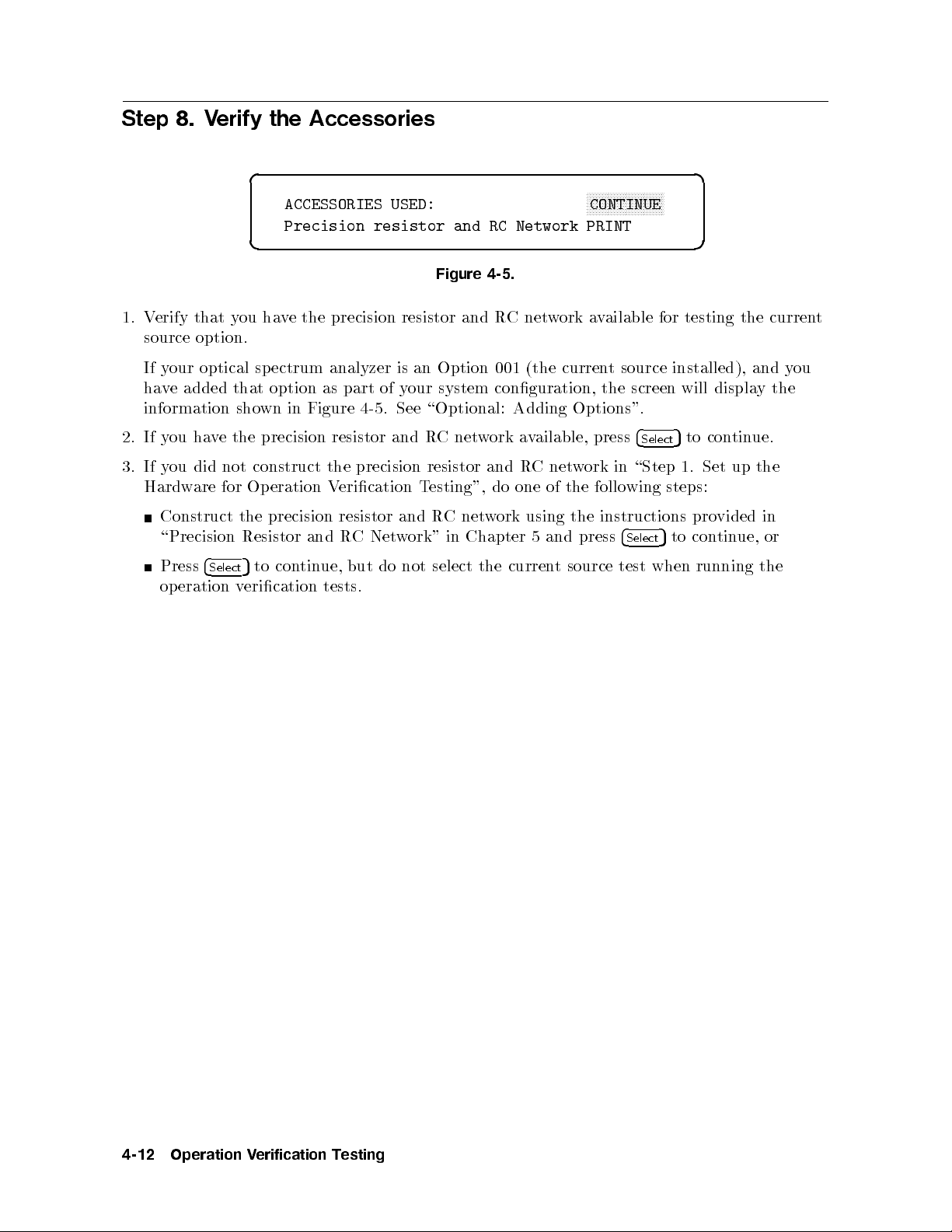
Step 8. Verify the Accessories
d a
NNNNNNNNNNNNNNNNNNNNNNNNNN
ACCESSORIES USED:
CONTINUE
Precision resistor and RC Network PRINT
c b
Figure 4-5.
1. Verify that you have the precision resistor and RCnetwork available for testing the current
source option.
If your optical sp ectrum analyzer is an Option 001 (the current source installed), and you
have added that option as part of your system conguration, the screen will displaythe
information shown in Figure 4-5 . See \Optional: Adding Options".
2. If you have the precision resistor and RCnetwork available, press
in
ork
w
net
C
R
net
C
Chapter
in
and
w
the
do
ork
curren
one
using
5and
of
t
follo
the
instructions
the
press
source
3.
If
Hardw
did not
ou
y
are for
Construct
\Precision
4
Press
op
Select
eration
construct the
Operation
precision
the
Resistor
tin
con
to
5
erication
v
V
and
ue,
tests.
precision resistor
esting",
and
w
not
T
R
ork"
select
erication
resistor
Net
C
R
but do
\Step
wing
4
Select
test
4
Select
when
5
to continue.
Set
1.
steps:
pro
con
to
5
running
up
vided
ue,
tin
the
in
or
the
4-12
Operation
erification
V
esting
T
Page 75
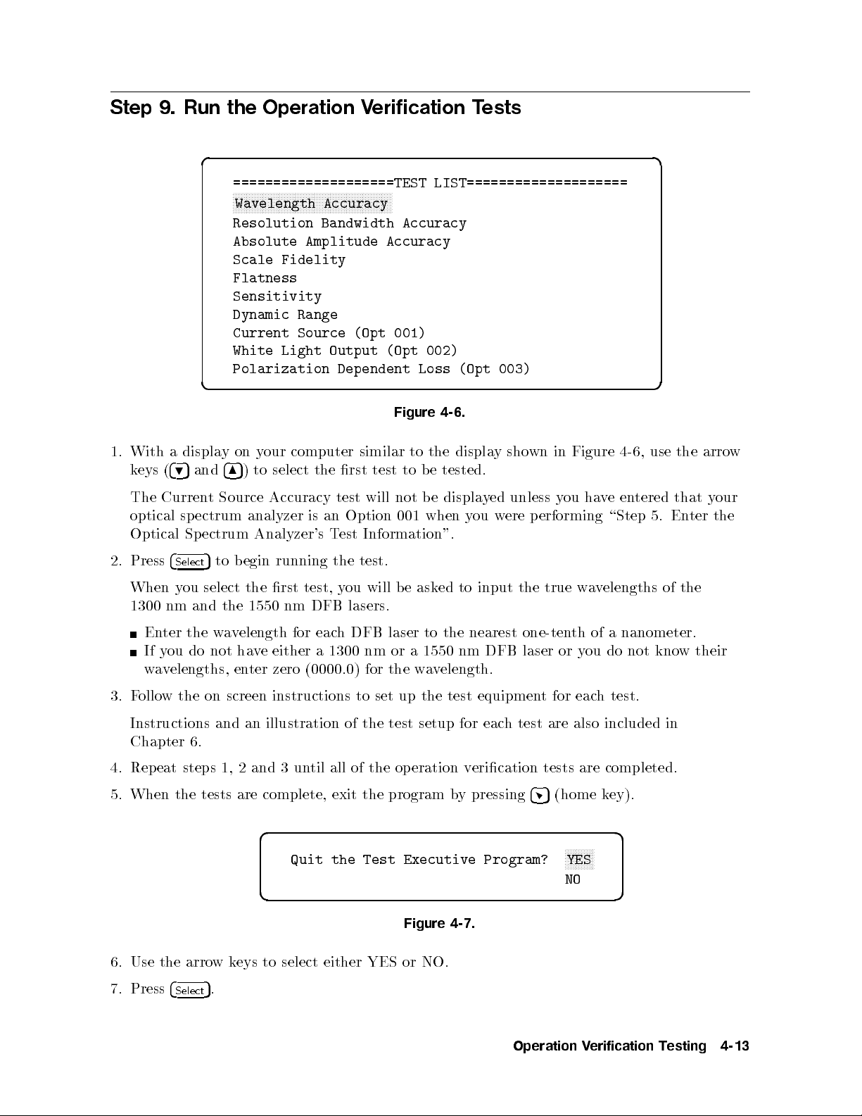
Step 9. Run the Operation Verification Tests
d a
====================TEST LIST====================
NNNNNNNNNNNNNNNNNNNNNNNNNNNNNNNNNNNNNNNNNNNNNNNNNNNNNNNNNNN
Wavelength Accuracy
Resolution Bandwidth Accuracy
Absolute Amplitude Accuracy
Scale Fidelity
Flatness
Sensitivity
Dynamic Range
Current Source (Opt 001)
White Light Output (Opt 002)
Polarization Dependent Loss (Opt 003)
c b
Figure 4-6.
sho
y
displa
the
test
to
not
001
to
e
b
e
b
when
tested.
displa
ou
y
y
ed
w
unless
ere
1.
With a
(
eys
k
Curren
The
optical
Optical
display
4
5
9
sp
Sp
4
and
8
Source
t
ectrum
ectrum
our
on y
select
to
)
5
Accuracy
analyzer
Analyzer's
computer
rst
the
test
an
is
est
T
similar
will
Option
Information".
Figure
in
wn
ou
y
erforming
p
ha
e
v
\Step
4-6
en
use
,
tered
5. En
arro
the
that y
ter
w
our
the
test.
test,
DFB
eac
for
(0000.0)
the
will
ou
y
lasers.
DFB
h
1300 nm
for
e
b
laser
or a
the
ask
to
1550
w
a
to
ed
the
nm
elength.
v
input
nearest
DFB
true
the
one-tenth
or
laser
w
y
a
of a
ou
elengths
v
nanometer.
not
do
2.
Press
When
1300
En
If
av
w
y
4
nm
ter
ou
Select
ou
y
and
the
do
to
5
select
w
not
elengths, en
begin
the
elength
v
a
ha
running
the rst
nm
1550
either a
ve
ter zero
3. Follow the on screen instructions to set up the test equipment for each test.
Instructions and an illustration of the test setup for each test are also included in
Chapter 6.
completed.
are
4
tests
(home
5
k
ey).
4.
5.
eat
Rep
When
steps
the
2
1,
are complete,
tests
and
erication
eration
the
op
program
of the
all
til
un
3
exit
v
pressing
y
b
d a
NNNNNNNNNNN
Quit the Test Executive Program?
YES
NO
c b
Figure 4-7.
NO.
or
6.
Use
the
arro
either
select
to
eys
k
w
YES
of
kno
the
w
their
7.
Press
4
Select
.
5
Operation
erification
V
esting
T
4-13
Page 76

Optional: Selecting the Optical Spectrum Analyzer's Address
If your optical sp ectrum analyzer's address is set to an address other than the factory
preset address of 723, you maychange this software to op erate using your optical spectrum
analyzer's current address.
d a
============UUT: HP70951A============
SERIAL NUMBER 3141A00056
ADDRESS TYPE HP-IB
NNNNNNNNNNNNNNNNNNNNNNNNNNNNNNNNNNNNNNNNNNNN
ADDRESS 723
CONTROLLER
OPTIONS
TEMPERATURE 23.0 DEG C
HUMIDITY 50.0 %
LINE FREQUENCY 60 Hz
c b
1.
2.
3.
4.
With
default
The
the
Use
b
um
n
Use
Use
Press
Return
tin
con
displa
a
er.
the
the
4
to
ue.
arro
4
4
(home
5
step
on
y
address
k
w
and
5
6
and
5
9
3
eys
k
y
the
the
ey).
of
our
for
4
(
,
5
6
4
7
4
8
\Step
computer
optical
the
4
4
,
5
5
7
9
v
mo
to
5
hange
c
to
5
En
5.
similar
sp
4
and
the
e
the
ter the
Figure
to
ectrum
c
to
)
5
8
cursor
digit
Optical Sp
4-8.
y
displa
the
analyzer
hange
the
to
to
is
the
appropriate
h
matc
ectrum Analyzer's
wn
sho
723.
address
correct
the
in Figure
correct
the
to
address
address
Test
press
4-8,
address
digit.
er.
b
um
n
Information"
4
Select
5
to
.
4-14
Operation
erification
V
esting
T
Page 77

Optional: Adding Options
If your optical sp ectrum analyzer has an option installed, you will need to enter the option
information to ensure that your optical spectrum analyzer is tested completely.
d a
============UUT: HP70951A============
SERIAL NUMBER 3141A00056
ADDRESS TYPE HP-IB
ADDRESS 723
CONTROLLER
NNNNNNNNNNNNNNNNNNNNNNNNNNNNNNNNNNNNNNNNNNNNNNNNNN
OPTIONS
TEMPERATURE 23.0 DEG C
HUMIDITY 50.0 %
LINE FREQUENCY 60 Hz
c b
Figure 4-9.
1. With
a displa
computer
our
y
on
y
similar
to
Figure
in
wn
sho
y
displa
the
4-9
Select
4
press
,
d a
5
.
the
Use
2.
a
With
3.
to select either
NNNNNNNNNNN
YES
and
etween
b
4.
Press
45
4
and
5
9
on
y
displa
NNNN
YES
NNNNNNNN
NO
are not sho
NNNNNNNNNN
N
and
YES
(home key).
============UUT:
SERIAL
ADDRESS
NUMBER
TYPE
ADDRESS
CONTROLLER
N
N
NN
N
N
N
N
N
N
N
N
N
N
N
N
N
N
N
N
N
N
N
N
N
N
N
N
N
N
N
N
N
N
N
HP70951A============
3141A00056
HP-IB
723
N
N
N
N
N
N
NN
N
N
N
N
N
N
N
OPTIONS
==========UUT
N
N
N
N
N
N
N
N
NN
001
NN
NN
N
N
N
N
N
N
N
N
N
N
N
N
N
NO
002 NO
OPTIONS===========
N
N
N
N
N
N
N
N
N
N
N
N
N
N
N
N
N
N
N
N
Current
White
NN
N
N
N
NN
N
N
N
N
N
N
N
N
Source
Light
N
N
N
N
N
N
N
N
N
N
N
N
N
N
N
N
N
N
N
N
N
N
NN
NN
N
N
N
N
N
N
N
N
N
N
added
added
003 NO PDL added
LINE FREQUENCY 60 Hz
c b
Figure 4-10.
time.
a
at
the
NNNNNNN
y
NNNNNNN
N
NO
4
our
or
highligh
to
5
8
computer
NNNN
NNNN
NO
.
wn on the displa
.
the
t
similar
the
options,
display
installed
to
y at the same
one
Figure
in
wn
sho
time. Pressing
4-10
4
Select
press
,
5
toggles
4
Select
5
5.
Return
tin
con
ue.
to
step
Information"
est
ectrum
ter the
En
\Step
of
3
5.
Optical
Sp
Analyzer's
Operation
T
erification
V
esting
T
to
4-15
Page 78

Optional: Modifying the Temperature Setting
You mayenter the ambient room temperature in which the optical spectrum analyzer is
operating. This temp erature b ecomes part of the test record.
d a
============UUT: HP70951A============
SERIAL NUMBER 3141A00056
ADDRESS TYPE HP-IB
ADDRESS 723
CONTROLLER
OPTIONS
NNNNNNNNNNNNNNNNNNNNNNNNNNNNNNNNNNNNNNNNNNNNNNN
TEMPERATURE 23.0 DEG C
HUMIDITY 50.0 %
LINE FREQUENCY 60 Hz
c b
Figure 4-11.
press
,
degrees
in
4-11
Celsius
1. With
The default
a displa
our
y
on
y
temperature
computer
23.0
is
similar
degrees
the
to
Celsius.
displa
Only
sho
y
temp
in
wn
eratures
Figure
4
Select
5
only
.
.
2.
3.
4.
the
Use
erature.
temp
Use
Use
Press
Return
tin
con
the
the
4
ue.
arro
(home
5
to
w
4
5
6
4
5
9
step
k
and
and
3
eys
k
the
the
ey).
of
4
(
,
5
6
4
7
4
8
\Step
correct
the
temp
temp
to
erature
erature
est
T
digit.
b
um
n
Information"
er.
to
erature
temp
to
the
appropriate
the
matc
ectrum
Sp
the
h
Analyzer's
correct
hange
4
4
,
5
7
9
mo
to
5
hange
c
to
5
En
5.
5
and
e
v
ter
the
the
4
8
the
c
to
)
5
cursor to
digit
Optical
4-16
Operation
erification
V
esting
T
Page 79

Optional: Modifying the Humidity Setting
You mayenter the humidity of the ro om in which the optical spectrum analyzer is operating.
This humidity becomes part of the test record.
d a
============UUT: HP70951A============
SERIAL NUMBER 3141A00056
ADDRESS TYPE HP-IB
ADDRESS 723
CONTROLLER
OPTIONS
TEMPERATURE 23.0 DEG C
NNNNNNNNNNNNNNNNNNNNNNNNNNNNNNNNNNNNNNNNNNNNNNN
HUMIDITY 50.0 %
LINE FREQUENCY 60 Hz
c b
Figure 4-12.
4
press
,
the
4-12
correct
umidit
h
Select
y
.
1. With
The default
Use
2.
a displa
arro
the
on
y
humidit
eys
k
w
y
our
y
4
(
computer
50
is
4
,
5
5
6
7
ercen
p
4
,
9
5
similar
t.
and
Figure
in
wn
sho
y
displa
the
to
to
umidit
h
hange
4
8
c
to
)
5
the
y
5
.
Use
Use
Press
3.
4. Return
tin
con
the
the
4
5
to step
ue.
4
and
5
6
4
5
9
(home
and
3
k
of
the
the
ey).
4
7
4
8
\Step
digit.
umidit
h
T
y
um
n
y
Information"
est
er.
b
to
umidit
cursor
the
e
v
mo
to
5
ter
the
the
hange
c
to
5
En
5.
to
digit
Optical
to matc
ectrum
Sp
the
h
Analyzer's
appropriate
the
h
correct
Operation
erification
V
esting
T
4-17
Page 80

Optional: Selecting the Line Frequency
You mayenter the line frequency that the optical sp ectrum analyzer is using to operate. This
line frequency is recorded with the test record.
d a
============UUT: HP70951A============
SERIAL NUMBER 3141A00056
ADDRESS TYPE HP-IB
ADDRESS 723
CONTROLLER
OPTIONS
TEMPERATURE 23.0 DEG C
HUMIDITY 50.0 %
NNNNNNNNNNNNNNNNNNNNNNNNNNNNNNNNNNNNNNNNNNNNNNN
LINE FREQUENCY 60 Hz
c b
Figure 4-13.
1. With
a displa
computer
our
y
on
y
similar
to
Figure
in
wn
sho
y
displa
the
4-13
Select
5
4
press
,
d a
.
============UUT:
SERIAL
ADDRESS
NUMBER
TYPE
ADDRESS
HP70951A============
3141A00056
HP-IB
723
CONTROLLER
OPTIONS
TEMPERATURE
HUMIDITY
N
N
N
N
N
N
N
N
N
N
N
NN
LINE
N
N
N
N
N
N
N
N
N
NN
NN
NN
NN
N
N
N
N
N
N
FREQUENCY
N
N
NN
NN
NN
NN
N
N
N
N
23.0
%
50.0
N
NN
N
N
N
N
N
N
N
N
N
N
N
60
Hz
C
DEG
60 Hz
50 Hz
400 Hz
c b
Figure 4-14.
2.
With
keys (
displa
a
4
5
9
and
computer
our
y
on
y
4
5
) to select the line
8
similar
the displa
to
y
Figure
in
wn
sho
frequency that the optical spectrum analyzer is using.
4-14
arro
the
use
,
The default line frequency is 60 hertz.
Press
4
3.
Select
.
5
4. Return to step 3 of \Step 5. Enter the Optical Spectrum Analyzer's Test Information" to
continue.
w
4-18
Operation
erification
V
esting
T
Page 81
Optional: Changing the Default Equipment
Use the following procedure if your test equipment model numbers and addresses are dierent
from the default test equipment that was displayed when you veried the test equipment.
These instructions are a continuation from step 3 of \Step 7. Verify the Test Equipment".
This software only supports the equipmentshown in Table 4-1 on the next page. To perform
this procedure, you must have BASIC 5.13 or above and the language extensions specied in
\Step 2. Install the Software on an SRM or HFS Hard Disk" installed on your computer.
The
TSCRIPT MS
le contains the mo del numbers and HP-IB addresses of the test
equipment and the test equipment required for each operation verication test. In this
procedure, you will edit, save, and run the TSCRIPT MS le.
Step 1. Print the Default Equipment List
If you have a printer connected to your computer, you can print the default test equipment
list when you are in the test equipment screen. Refer to Figure 4-4. To print the list:
1.
Use the arrowkeys (
495
and
485
) to select
NNNNNNNNNNNNNNNNN
PRINT
on the display.
2.
Step 2.
1.
2.
3.
4.
Press
Use
Press
This
Press
ou
Y
es.
y
Press
4
Select
Exit the
arro
the
4
Select
displa
4
(home
5
b
will
4
Select
.
5
w
.
5
the
ys
ask
e
.
5
Operation
4
(
eys
k
ed
k
op
ey).
if
5
9
eration
ou
y
and
w
v
an
erification
V
4
8
select
to
)
5
erication
quit
to
t
test
the
Softw
N
N
N
N
NN
NN
N
N
CONTINUE
men
test
This will exit the operation verication test software.
Step 3. Load the TSCRIPT MS File
In
1.
this
yp
T
pro
e
cedure,
GET
y
"TSCRIPT_MS"
and
press
4
Return
MS
.
5
TSCRIPT
the
load
will
ou
portion of the computer screen to disapp ear.
2. T
ype
EDIT
and press
4
Return
Wait for the TSCRIPT
5
.
screen.
are
N
N
N
N
N
N
N
N
N
N
N
N
N
N
N
N
u.
executiv
le.
ait for
W
displa
the
on
e program.
asterisk
the
MS le
.
y
The default
lo
the
in
selection
righ
er
w
is
t
to appear on the computer
Operation
erification
V
esting
T
4-19
Page 82

Step 4. Edit the Test Equipment and HP-IB Address Lists
In this procedure, you will edit the TSCRIPT MS le's test equipment and HP-IB address
lists.
If your test equipmentmodelnumbers and HP-IB addresses do not match the operation
verication software's test equipment mo del numbers and HP-IB addresses, you will need to
edit the lists in the TSCRIPT MS le.
If you do not have an optical attenuator or a polarization controller available as part of your
test equipment, refer to \Step 6. Select Where You Want to Output the Test Results".
1. Scroll to the
CALIBRATION_STANDARDS(
section of the le. This section of the
TSCRIPT MS le shows the default list of test equipment. The variable names with
corresponding descriptions are shown in Table 4-1.
Table 4-1. Test Equipment Variable Names
Variable
Name
W1
L
L
W2
ligh
ligh
LW3 light
W4
L
ligh
PM1 ligh
TTN
A
D
VM
optical
digital
PL p
Description Default
e
v
a
w
t
e source
v
a
w
t
e
v
a
w
e
v
a
w
t
e
av
w
t
atten
oltage
v
olarization
source
source
source
m
1
2
3
4
ultimeter
uator
meter
troller
con
1
Alternate
Model Number
WHITE-LIGHT A
83425A
HP
Model Numbers
4304
Q
83420A
HP
83421A
HP
HP 83424A HP 83420A
HP 83421A
4302
Q
A
HP
HP
HP
HP
8153A
8157A
3456A
11894A
HP
HP
HP
HP
8153B
8157B
3455A,
3458A
Option
Option
Option
Option
210,
210
220,
220
SA1 optical spectrum analyzer HP 70951B
2. Edit the default list of test equipment as needed. Refer to Table 4-1 for a default mo del
and
ers
b
um
n
example,
or
F
HP 3456A digital v
cursor under the
there is no space
3. Scroll to the
alternate
their
wish
ou
y
if
oltmeter, scroll do
6
and t
weenHPand
bet
DEFAULT_ADDRESSES(
mo
substitute
to
8
ype
v
sa
to
5
Return
ultimeter
m
line. Then, position the
DVM(HP3458A)
over the
3458A
HP 3458A
the
wn to the
6
. The
.
digital
DVM(HP3456A)
result should be
section of the le and edit the equipmen
hange.
c
the
e
the
of
place
in
. Note that
t addresses in a
4
Press
ers.
b
um
del n
manner similar to the example in step 2 of this pro cedure.
Valid addresses are 00 to 30. Valid select co des are 0 through 5 and 7 through 9. The
default
is
7.
Do not
set
the
equipmen
addresses
t
to
an
y
addresses
used
under
unit
the
y
b
test.
esting
4-20
Operation
erification
V
T
Page 83
Step 5. Edit the Required Test Equipment Lists
In this procedure, you will edit the TSCRIPT MS le to delete optional equipmentfrom
operation verication tests.
If you do not have an optical attenuator or a p olarization controller available as part of your
test equipment, you can still perform the wavelength accuracy and the resolution bandwidth
accuracy tests. The optical attenuator and the polarization controller are optional equipment
for these two tests. This procedure will showyou how to edit the TSCRIPT MS le so that
you may perform the wavelength accuracy and the resolution bandwidth accuracy tests
without the optical attenuator and the polarization controller.
1. Move the cursor to the following line of the TSCRIPT MS le:
TEST(TN(Wavelength Accuracy) TP(Wave_accy) TR(Report_gen)
2. Move the cursor down one more line to the
3. Use the
4
Delete line
5
key to delete all ve lines of the
"SETUP ALL1"
"SETUP ALL1"
line of the test.
section.
4. Move the cursor to the following line of the TSCRIPT MS le:
TEST(TN(Resolution Bandwidth Accuracy) TP(Resolution) TR(Report_gen)
test.
the
of
le
4
er
w
for the
line
and
Return
righ
ALL2"
restart
sa
5
to
ortion
p
t
asterisk (*)
section.
the
the
e
v
of
the cursor
e
v
Mo
5.
Use the
6.
Sa
6.
Step
pro
this
In
erication
v
1. Press
4
Stop
TSCRIPT MS
ype
tp
to
ortion
2.
screen
T
righ
3. Type
When
Done.
one more
down
4
Delete
the
e
v
cedure,
test
t
5
,
turn
5
line
TSCRIPT
ou
y
w
soft
e
yp
le.
o.
key
are.
RE-SAVE
will
W
to
ait
delete
v
sa
for
e
LOAD "C_TSCRIPT_MS"
computer
the
of
RUN
and press
4
Return
appears on the computer screen, the op eration verication software is ready
four
File's
the
lines
TSCRIPT
MS
the
line to
all
edited
"TSCRIPT_MS"
asterisk
the
and press
turn
screen
5
.
to
"SETUP
Edits
,
(*)
4
Return
o.
of
and
in
the
the
.
5
ALL2"
"SETUP
MS
press
lo
Wait
to load and run.
eration
op
edited
the computer
er
w
in the
lo
4. Con
Optical Sp
tinue at beginning of the operation verication software. Refer to \Step 4. Select the
del".
ectrum
Analyzer's
Mo
Operation
erification
V
esting
T
4-21
Page 84

Optional: Running the Operation Verification Tests from a Flexible
Disk Drive
To run the op eration verication test software, you must have a BASIC programming
language loaded into the computer. There are several binaries (BIN les) that must be loaded
also.
1. Load BASIC 5.13 or later, with the appropriate BIN les, into the HP 9000 Series 300
computer. If necessary, refer to an HP BASIC reference manual.
The BIN les that should be loaded are listed below. Refer to Table 5-2 for a description of
each le.
CLOCK EDIT KBD
COMPLEX ERR MAT
CRTA GRAPH MS
CRTB GRAPHX PDEV
CRTX HFS* SRM
z
y
CS80 HPIB TRANS
DISC IO XREF
z
system)
le
to
Return
and
hical
resource
the
5
.
insert
driv
management)
ou
ey
2.
Disk
will
Press
*Optional: required
y
Optional:
z
Optional:
example:
or
MSI
e
Disk
the
":,700,0"
LOAD
prompted,
2.
3.
4.
5.
Insert
Assign
F
Typ
When
required
required
the
in
1
(mass
MSI
"OPV",1
only
only
only
disk
remo
for
for
for
driv
storage
press
and
Disk
e
v
(hierarc
HFS
(shared
SRM
DEBUG.
e.
is)
4
1
NNNNNNNNNNNNNNNNNNNNNNNNNN
If you have an HP 46021A keyboard, and the
display, press
4
Esc54System
5
.Ifyou have an HP 98203C keyboard, refer to \Computer
Continue
Keyboard Compatibility and Mouse Operation" in Chapter 5.
6.
Con
tin
at \Step
ue
4.
Select
the
Optical
ectrum
Sp
Analyzer's
vironmen
en
as
use
N
N
N
N
Continue
t.
environmen
default
the
N
N
N
N
N
N
N
N
N
NN
NN
NN
NN
N
N
t.
e.
driv
N
N
N
.
softkey does not app ear on the
del".
Mo
4-22
Operation
erification
V
esting
T
Page 85

5
Operation Verification Test Reference
Introduction
The topics in this chapter supplement the information in Chapter 4. This chapter includes
specic information regarding the computer system that is required to run the op eration
verication test software, detailed instructions on using the op eration verication test software
with dierentkeyboards or a mouse, and a complete listing of the test equipment required to
perform the operation verication tests. A description of a precision resistor and RC network
is also included in this chapter. The precision resistor and RC network is required for the
current source test.
Operation
erification
V
T
est
Reference
5-1
Page 86
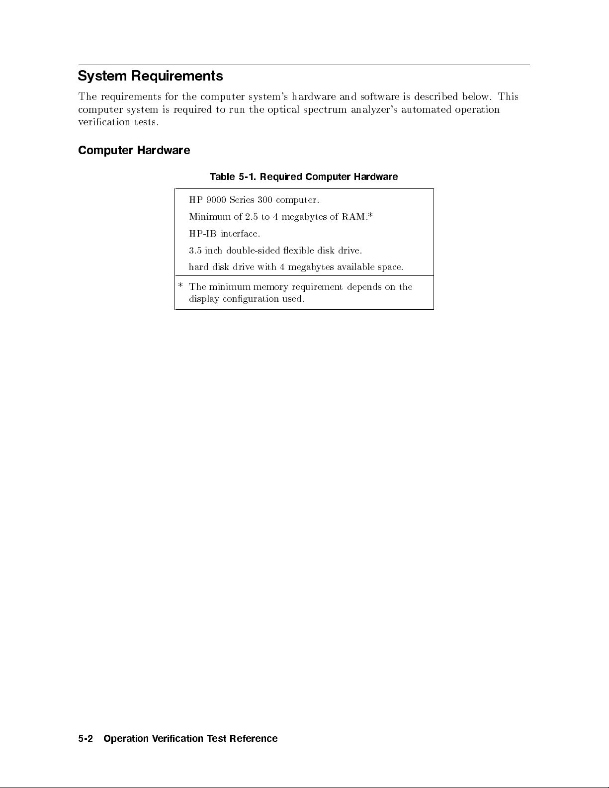
System Requirements
The requirements for the computer system's hardware and software is described below. This
computer system is required to run the optical spectrum analyzer's automated operation
verication tests.
Computer Hardware
Table 5-1. Required Computer Hardware
HP 9000 Series 300 computer.
Minimum of 2.5 to 4 megabytes of RAM.*
HP-IB interface.
3.5 inch double-sided exible disk drive.
hard disk drive with 4 megabytes available space.
* The minimum memory requirement depends on the
displa
conguration
y
used.
5-2
Operation
erification
V
T
est
Reference
Page 87

Operating System
The required operating system is BASIC 5.13 or later. Refer to Table 5-2 for the required
language extensions.
Table 5-2. Required BASIC 5.13 Language Extensions
Binary
Name Description
GRAPH provides graphics capability.
GRAPHX extends \GRAPH" by providing graphics input, color plotting, and
area-lling capabilities.
IO increases Input/Output (I/O) capability.
TRANS provides background Input/Output transfer capability and the use of
BUFFERs.
MAT increases array and matrix capabilities.
PDEV increases program development capability.
.
to
y
.
y
y
.
include
an
English
explanation of
the
XREF
CLOCK
MS
ERR
provides
increases
increases
extends
cross
a
time
mass
BASIC
reference
date
and
storage
error
capabilit
capabilit
capabilit
messages
error.
yp
t
HP-IB
displays.
disk
e
or
and
DISC
CS80
DCOMM
HPIB
A
T
CR
COMPLEX
vides
pro
vides
pro
vides
pro
vides
pro
HP-IB
vides
pro
complex math
adds
the
the
a
the
terface.
in
the
device
device
device
terface
in
device
er
driv
er
driv
for
er
driv
driv
er
driv
functions, h
non-CS/80
for
CS/80 and
for
terfaces.
in
SRM
in
the
for
er
non-bit-mapped
for
yperb
ternal
olic
external
SS/80
functions,
complex data type.
CRTX provides several CRT display \eXtended" capabilities.
EDIT provides an editing environment for BASIC programs.
and
vides increased
KBD
SRM
pro
NEEDED)
(IF
manager)
pro
systems.
CRTB (IF NEEDED) pro
HFS (IF NEEDED) pro
softk
and
oard
eyb
k
statements
and
er
driv
a
vides
vides the device driv
vides a hierarc
hical le system and a few
capabilit
ey
er for bit-mapped displa
y
for
for managing les.
driv
disks.
the
SRM
es.
HP
the
HP-HIL
(shared
statements
98624
access.
resource
ys.
Operation
erification
V
T
est
Reference
5-3
Page 88
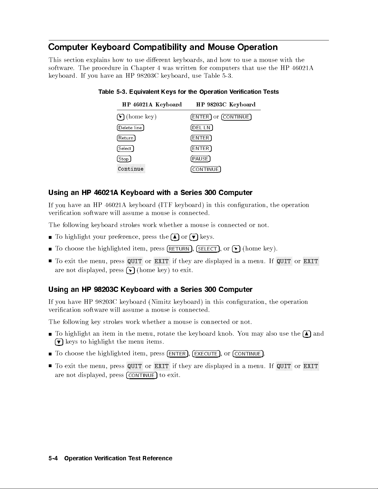
Computer Keyboard Compatibility and Mouse Operation
This section explains how to use dierentkeyboards, and how to use a mouse with the
software. The procedure in Chapter 4 was written for computers that use the HP 46021A
keyboard. If you have an HP 98203C keyboard, use Table 5-3.
Table 5-3. Equivalent Keys for the Operation Verification Tests
HP 46021A Keyboard HP 98203C Keyboard
45
Using
ha
ou
y
If
erication
v
follo
The
an
v
wing
HP
an
e
softw
46021A
46021A
HP
are will
oard
eyb
k
(home key)
4
Delete line
4
Return
4
Select
4
Stop
NNNNNNNNNNNNNNNNNNNNNNNN
5 4
5 4
5 4
5 4
Continue
Keyboard
keyb
assume
strokes
with
oard (ITF
mouse
a
whether
ork
w
is
4
ENTER
DEL LN
ENTER
ENTER
PAUSE
4
CONTINUE
Series
a
oard)
eyb
k
connected.
mouse
a
5or4
5
5
5
5
5
Computer
300
this
in
connected
is
CONTINUE
5
conguration,
or
not.
the
eration
op
N
N
N
N
N
N
NN
EXIT
ey)
with
4
8
4
RETURN
N
N
N
N
N
N
if
to
a
or
5
they
exit.
Series
4
eys.
k
5
9
4
5
,
SELECT
displa
are
300 Computer
4
or
5
,
5
(home
men
a
in
ed
y
u.
k
ey).
If
N
N
N
N
N
NN
QUIT
N
N
N
N
N
N
N
NN
or
o
T
To
o
T
are
Using
highligh
the
ose
ho
c
the
exit
not displa
HP
an
our
y
t
highligh
men
ed,
y
98203C
preference,
ted
press
u,
press
Keyboard
item,
N
N
N
N
N
NN
QUIT
4
5
N
press the
press
N
N
N
N
N
N
or
(home k
If you have HP 98203C keyboard (Nimitz keyboard) in this conguration, the operation
verication software will assume a mouse is connected.
The following key strokes work whether a mouse is connected or not.
To highlight an item in the menu, rotate the keyboard knob. You may also use the
items.
u
men
the
t
highligh
u, press
ed, press
y
item, press
ted
NNNNNNNNNNNN
QUIT
4
CONTINUE
4
ENTER
NN
or
NNNNNNNNNNNN
EXIT
5
to exit.
NN
if they are displa
4
,
5
EXECUTE
4
or
,
5
CONTINUE
yed in a men
.
5
u. If
NNNNNNNNNNNN
QUIT
ose
highligh
the
495
T
o
eys to
k
ho
c
To exit the men
are not displa
485
NN
NNNNNNNNNNNN
or
N
N
N
N
N
N
N
EXIT
EXIT
N
N
N
N
N
and
NN
5-4
Operation
erification
V
T
est
Reference
Page 89
Using a Mouse with a Series 300 Computer
The menus in the op eration verication test software use a window format, displaying the
choices available in that menu.
To highlight your preference, slide the mouse up or down.
Tocho ose the highlighted item, press the left-hand button on the mouse, or slide the mouse
to the right.
To exit the menu, press
NNNNNNNNNNNNNN
QUIT
or
NNNNNNNNNNNNNN
EXIT
if they are displayed in a menu. If
NNNNNNNNNNNNNN
QUIT
or
NNNNNNNNNNNNNN
EXIT
are not displayed, slide the mouse to the left to exit.
Recommended Test Equipment
The test equipment required to perform the operation verication tests is listed in Table 5-4.
If the recommended test equipmentisnotavailable, alternate equipmentmay be used if it
meets the critical specications in the table.
the optical
If
spectrum
precision resistor
ork
w
net
C
R
and
C
R
resistor
and
section.
tec
A
eration
op
the
hnical
eginning
b
computer
erication tests
v
of
and R
not
is
w
net
this
analyzer b
C net
listed
are
ork
its
and
but
hapter.
c
eing
is
work
able
T
in
included
erating
op
not
are
tested
required
ho
;
5-4
\Precision
in
system
listed
an
is
test
to
er,
ev
w
required to
is
able
T
in
the
001
curren
Option
instructions
Resistor
Refer
.
5-4
(curren
t
and
erform
p
source
t
source.
for
RC
to
The
constructing the
ork"
Netw
automated
the
\System
option),
precision
resistor
precision
follo
the
in
Requiremen
a
wing
ts"
at
Operation
erification
V
T
est
Reference
5-5
Page 90
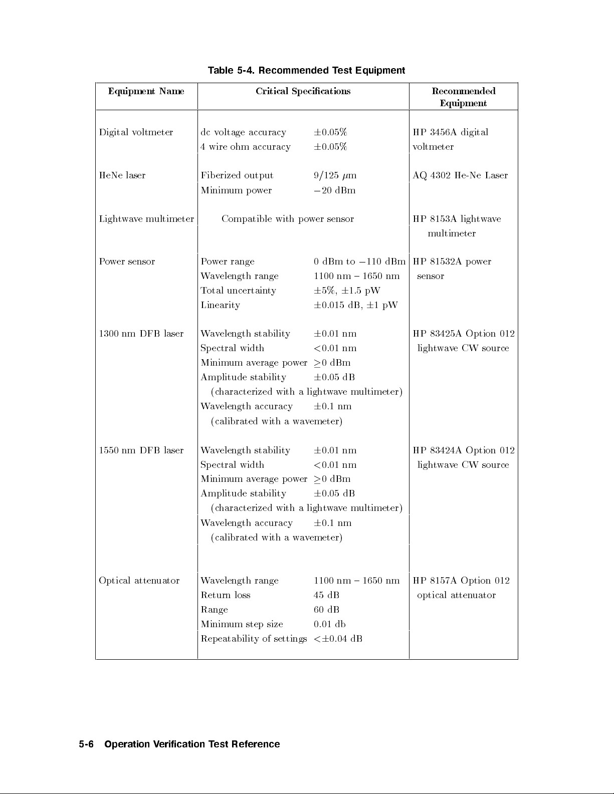
Table 5-4. Recommended Test Equipment
Equipment Name Critical Specications Recommended
Equipment
Digital voltmeter dc voltage accuracy
4 wire ohm accuracy
6
0.05% HP 3456A digital
6
0.05% voltmeter
HeNe laser Fiberized output 9/125m AQ 4302 He-Ne Laser
Minimum power
0
20 dBm
Lightwavemultimeter Compatible with power sensor HP 8153A lightwave
multimeter
Power sensor Power range 0 dBm to0110 dBm HP 81532A power
Wavelength range 1100 nm { 1650 nm sensor
1300
nm DFB
laser
Total uncertainty
Linearit
W
Sp
Minim
Amplitude
y
elength stabilit
av
width
ectral
erage
v
a
um
stabilit
(characterized
elength
v
a
W
(calibrated
accuracy
with
p
y
with
a
y
o
er
w
a
a
w
6
6
6
<
6
ligh
6
emeter)
v
5%,61.5 pW
nm
nm
dB
e
v
nm
m
6
ultimeter)
0.015 dB,
0.01
0.01
dBm
0
0.05
a
w
t
0.1
pW
1
83425A Option
HP
v
a
w
t
ligh
e
CW
012
source
1550 nm
DFB
Optical atten
laser
uator
nm
0.01
6
erage
y
nm
0.01
<
dBm
0
er
w
o
p
6
0.05 dB
um
stabilit
width
v
a
elength
v
Wa
ectral
Sp
Minim
Amplitude stability
(characterized with a lightwavemultimeter)
Wavelength accuracy
6
0.1 nm
(calibrated with a wavemeter)
Wavelength range
Return loss
1100 nm { 1650 nm
45 dB
Range 60 dB
Minimum step size
Repeatability of settings
0.01 db
<60.04 dB
HP 83424A
e
v
a
w
t
ligh
Option
CW
012
source
HP 8157A Option 012
optical atten
uator
5-6
Operation
erification
V
T
est
Reference
Page 91
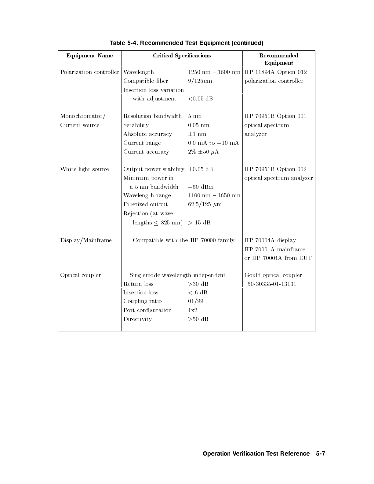
Table 5-4. Recommended Test Equipment (continued)
EquipmentName Critical Specications Recommended
Equipment
Polarization controller Wavelength 1250 nm { 1600 nm HP 11894A Option 012
Compatible b er 9/125m polarization controller
Insertion loss variation
with adjustment
<
0.05 dB
Monochromator/ Resolution bandwidth 5nm HP 70951B Option 001
Current source Setability 0.05 nm optical spectrum
Absolute accuracy
6
1nm analyzer
Current range 0.0 mA to010 mA
Current accuracy 2%650A
White light source Output power stability60.05 dB HP 70951B Option 002
Minimum power in optical spectrum analyzer
nm
5
a
elength
v
a
W
erized
Fib
Rejection
lengths
bandwidth
range
output
e-
v
a
w
(at
nm)
825
60 dBm
0
nm
1100
62.5/125
15 dB
>
{
1650
m
nm
Displa
Optical
y/Mainframe
coupler
HP
the
loss
de
with
w
elength
v
a
indep
30 dB
>
<
6
Compatible
Singlemo
Return
Insertion
loss
Coupling ratio 01/99
Port conguration 1x2
Directivity
50 dB
70000
enden
dB
family
t
70004A
HP
70001A
HP
HP
or
Gould
displa
mainframe
70004A
optical
coupler
50-30335-01-13131
from
y
EUT
Operation
erification
V
T
est
Reference
5-7
Page 92
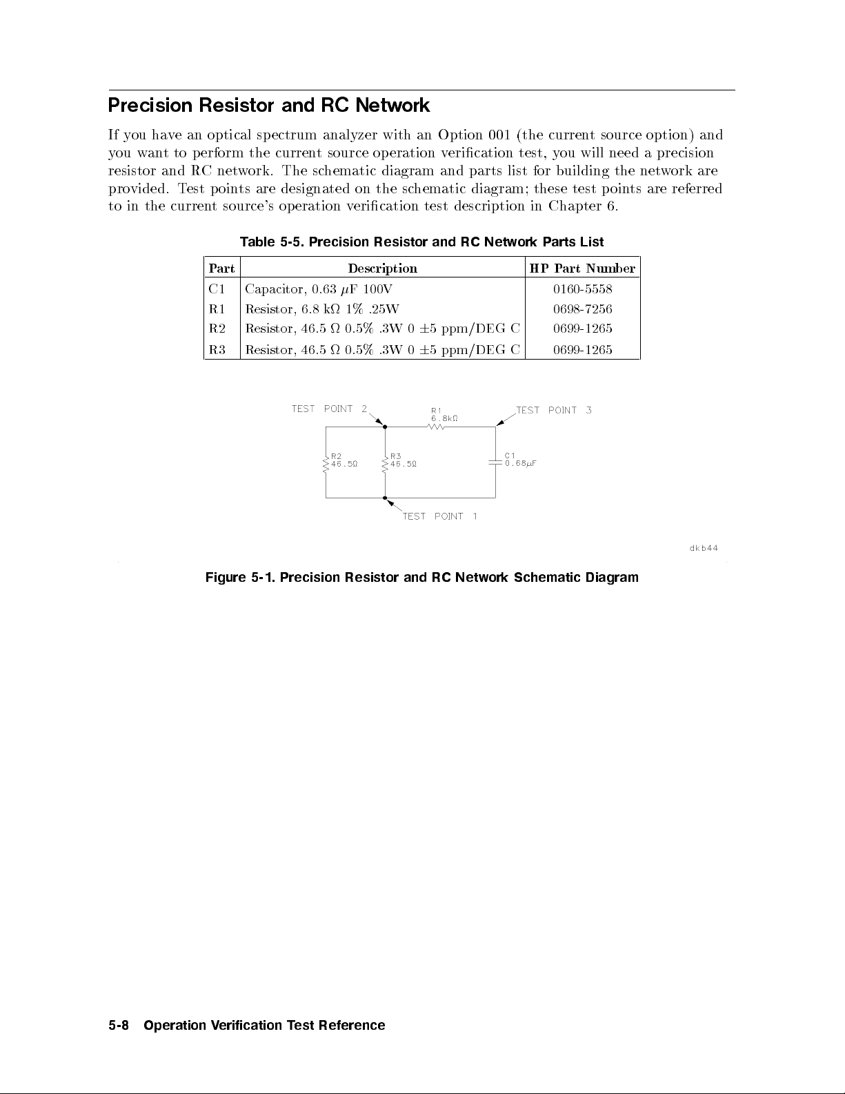
Precision Resistor and RC Network
If you have an optical sp ectrum analyzer with an Option 001 (the current source option) and
you want to perform the current source operation verication test, you will need a precision
resistor and RC network. The schematic diagram and parts list for building the network are
provided. Test points are designated on the schematic diagram; these test points are referred
to in the current source's op eration verication test description in Chapter 6.
Table 5-5. Precision Resistor and RC Network Parts List
Part Description HP Part Number
C1 Capacitor, 0.63F 100V 0160-5558
R1 Resistor, 6.8 k 1% .25W 0698-7256
R2 Resistor, 46.5 0.5% .3W 065 ppm/DEG C 0699-1265
R3 Resistor, 46.5 0.5% .3W 065 ppm/DEG C 0699-1265
Figure
5-1.
Precision
Resistor
and
RC
Netw
Schematic
ork
Diagram
5-8
Operation
erification
V
T
est
Reference
Page 93

6
Operation Verification Test Descriptions
Introduction
Operation verication tests are designed to giveyou a high condence level that your optical
spectrum analyzer is working properly. These tests are also designed to be completed in the
least time possible.
All op eration verication tests are automated and are designed to be controlled bya
computer. However, three of the op eration verication tests also havemanual versions of the
test. These manual op eration verication tests are designed to b e used if you do not havethe
specic test equipment required for the automated version of the test.
man
o
Tw
ectrum
sp
hapter.
c
following
The
Automated
a
W
Resolution
Absolute
Scale
Flatness
Sensitivit
Dynamic
Curren
erational
op
ual
analyzer mo
These
instrumen
is
est
T
elength
v
Bandwidth
Amplitude
Fidelit
erication
V
y
Range
Source,
t
list
a
Accuracy
y
c
dule's additional
des
mo
t
eration
op
the
of
cedures
Pro
(Automated)
Accuracy
Accuracy
(Automated)
Option
001
designed to
ks,
hec
White Light Output Power, Option 002
PDL System Accuracy, Option 003
Manual Test Procedures
Wavelength Accuracy (Manual)
ual)
ual)
(Man
for the HP 70951B optical spectrum analyzer mo dule
ks
k
Dynamic
Flatness
Range
(Man
Manual Operational Chec
Transimp edance Input Chec
Monoc
hromator Output/Photo detector Input Chec
are
not
verify
instrument
eried
v
erication
v
the functionalit
included
automated
the
are
modes,
y
b
tests:
k
yof
tests.
the
at
HP
the
70951B
of
end
optical
this
Operation
erification
V
Descriptions
est
T
6-1
Page 94
The operation verication test descriptions and pro cedures describe the operation verication
tests for the HP 70950B/1B/2B. However, the input of the monochromator for the HP
70950B/2B and for the HP 70951B are labeled dierently. In this chapter, the term
input
refers to both the HP 70950B/2B's OPTICAL INPUT and to the HP 70951B's
MONOCHROMATOR INPUT.
Unless otherwise specied, optical connections should b e made with 9/125m patchcords
using FC/PC or Diamond HMS 10 physical contact connector interfaces. To prevent damage
to your optical sp ectrum analyzer and ensure accurate measurements, clean all connectors and
optical input bers before beginning the operation verication tests.
optical
Note
To minimize interconnection changes, the HP 8157A optical attenuator and
the HP 11896A polarization controller are listed as standard equipment for all
tests. However, they are included in a test setup illustration only when they
are required by that test. If you haveveried model numbers and addresses
for the optical attenuator and polarization controller in \Step 7. Verify the
Test Equipment" in Chapter 4, the program will include them in the setup
directions.
6-2
Operation
erification
V
Descriptions
est
T
Page 95
Automated Test Procedures
Each automated operation verication test in this section summarizes the purpose of the
test, lists the equipment required to p erform the test, explains how the equipment is set up,
describes the test, and suggests the assemblies or items to check if the instrument fails the
operation verication test.
The measured results of the automated op eration verication tests are compared with the
specications for the optical sp ectrum analyzer. The operation verication software records
whether the measured results of the test meets the specications. Refer to \Specications and
Characteristics" in the Reference manual for the specications.
A list of test equipment required to perform these operation verication tests is located
in \Recommended Test Equipment" in Chapter 5 and in the equipmentlistofeachtest
description. The computer and its peripheral equipment are not listed in \Recommended
Test Equipment" in Chapter 5 or in the equipment list of each test. For details regarding
the computer, refer to \Step 1. Set up the Hardware for Operation Verication Testing" in
Chapter 4.
op
Some
tunable
analyzer
spectrum
referred
eration
optical
eing
b
analyzer
as
to
erication
v
lter to
tested is
with
\test
the
tests
test the
referred to
mono
the
system's
the
use
optical sp
as the
hromator
c
optical
sp
hromator
c
mono
ectrum analyzer
\optical sp
that
ectrum
ectrum
eing
b
is
analyzer."
an
of
under
analyzer
used
optical
test.
part
as
ectrum
sp
The
under
the
of
optical
test."
test
analyzer
sp
The
equipmen
as
ectrum
optical
t
a
is
Operation
erification
V
Descriptions
est
T
6-3
Page 96

Wavelength Accuracy (Automated)
This test measures the wavelength accuracy of the optical spectrum analyzer under test at
632.8 nm, and the wavelengths of the DFB lasers selected for the operation verication tests.
Equipment
HeNe laser
1300 nm DFB laser
1550 nm DFB laser (optional)
Equipment Setup
First, connect the HeNe laser's OUTPUT to the optical input of the optical sp ectrum analyzer
under test. Refer to Figure 6-1.
When
1300
the
analyzer
the
soft
nm
under
prompts
are
w
laser's
DFB
test. Refer
Setup
est
T
the
from
optical input
HeNe
of the
y
6-1.
ou,
Figure
OPTICAL
to Figure
a
W
remo
OUTPUT
6-2.
velength
the
e
v
Accuracy
connection
the
to
Figure 6-2. Wavelength Accuracy Test Setup 2
1
and
laser
optical sp
connect
ectrum
6-4
Operation
erification
V
Descriptions
est
T
Page 97

Description
The 1300 nm DFB laser and the 1550 nm DFB laser should have their wavelengths measured
and calibrated byawavemeter to the nearest tenth of a nanometer.
The wavelength measured on the optical spectrum analyzer in both rst and second order
operation is compared to the known wavelength of the HeNe laser (632.8 nm).
Then, with the 1300 nm DFB laser's OPTICAL OUTPUT connected to the optical input of
the optical spectrum analyzer under test, the optical sp ectrum analyzer under test is set to
automatic grating order. The center wavelength is set to the calibrated wavelength of the
1300 nm DFB laser. The dierence between the measured wavelength and the calibrated
wavelength of the 1300 nm DFB laser is compared to the sp ecication.
If the 1550 nm DFB laser is selected, the test is repeated for this source.
In Case of Failure
If this test fails, the following assemblies may need repair:
hromator
c
mono
A4
oard
b
trol
A2
motor
con
Operation
erification
V
Descriptions
est
T
6-5
Page 98
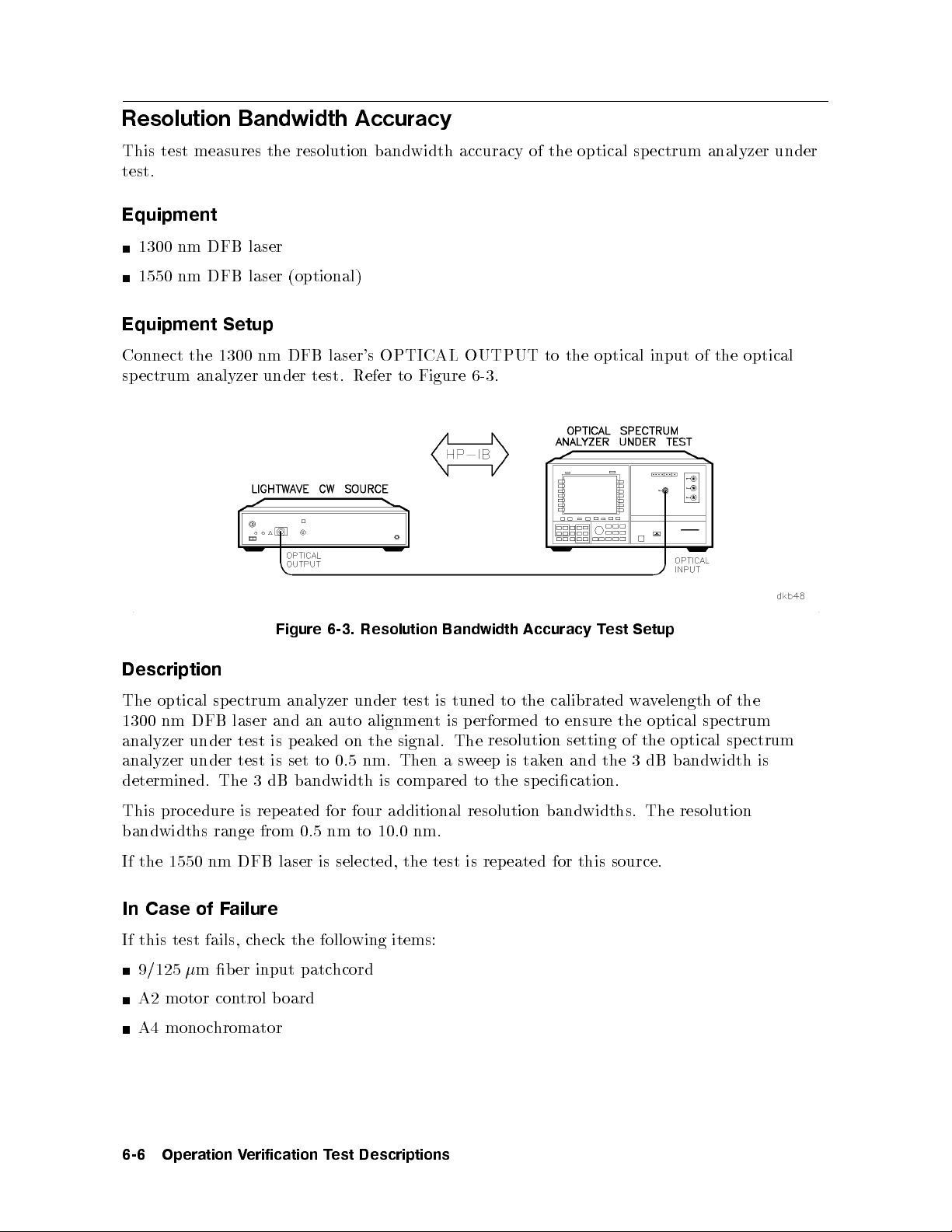
Resolution Bandwidth Accuracy
This test measures the resolution bandwidth accuracy of the optical spectrum analyzer under
test.
Equipment
1300 nm DFB laser
1550 nm DFB laser (optional)
Equipment Setup
Connect the 1300 nm DFB laser's OPTICAL OUTPUT to the optical input of the optical
spectrum analyzer under test. Refer to Figure 6-3.
Setup
est
Figure
Resolution
6-3.
Bandwidth
Accuracy
T
Description
the
The optical
DFB
nm
1300
analyzer
under
spectrum
laser
test
analyzer
an
and
eak
p
is
auto
ed
under
alignmen
the
on
tuned
is
test
p
is
t
signal. The
calibrated
the
to
ensure
erformed
to
resolution setting
a
w
the
of the
elength
v
optical
optical sp
of
spectrum
ectrum
analyzer under test is set to 0.5 nm. Then a sweep is taken and the 3 dB bandwidth is
determined. The 3 dB bandwidth is compared to the sp ecication.
This procedure is rep eated for four additional resolution bandwidths. The resolution
bandwidths range from 0.5 nm to 10.0 nm.
nm DFB
1550
the
If
In Case of F
ailure
If this test fails, c
laser
heck the following items:
9/125m ber input patc
selected,
is
hcord
the
source.
this
for
eated
rep
is
test
A2 motor control b oard
A4 monochromator
6-6
Operation
erification
V
Descriptions
est
T
Page 99

Absolute Amplitude Accuracy
This test measures the absolute amplitude accuracy and the polarization sensitivityofthe
optical spectrum analyzer under test.
Equipment
Optical attenuator
Polarization controller
Lightwavemultimeter
Power sensor
1300 nm DFB laser
1550 nm DFB laser (optional)
Equipment Setup
Connect
uator.
atten
olarization
p
of
input
OPTICAL
the
Connect
con
the ligh
of
of
OPTICAL
the
o
p
the optical
sensor.
er
w
attenuator
OUTPUT
to
Refer
to the
the p
of
Figure
OPTICAL INPUT
olarization con
.
6-4
troller.
e
v
a
tw
OUTPUT
OUTPUT
the
Connect
ultimeter's
m
INPUT
the
to
laser
DFB
nm
1300
the
Figure 6-4. Absolute Amplitude Accuracy Calibration Setup
of the
optical
troller
of
to
the
the
Operation
erification
V
Descriptions
est
T
6-7
Page 100
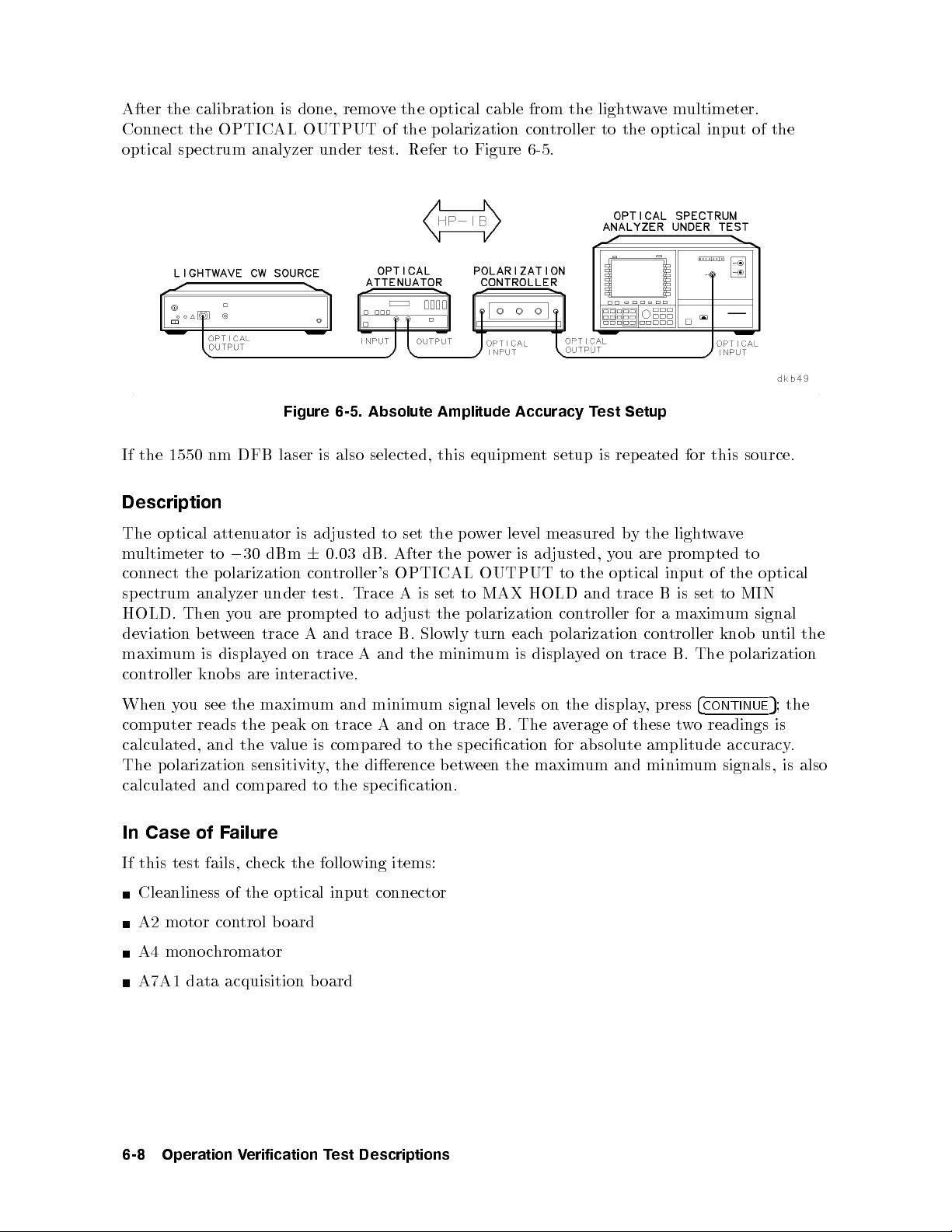
After the calibration is done, remove the optical cable from the lightwavemultimeter.
Connect the OPTICAL OUTPUT of the polarization controller to the optical input of the
optical spectrum analyzer under test. Refer to Figure 6-5.
Figure 6-5. Absolute Amplitude Accuracy Test Setup
If the 1550 nm DFB laser is also selected, this equipment setup is repeated for this source.
Description
e
v
a
w
t
ligh
the
y
optical
The
multimeter
connect
sp
HOLD.
the
ectrum
Then
deviation
maxim
con
um
troller
atten
30
to
0
olarization
p
analyzer
ou
y
een
w
et
b
displa
is
knobs
uator
dBm
under
are
trace
y
are
is
6
con
test.
prompted
A
on
ed
teractiv
in
adjusted
dB.
0.03
troller's
T
trace
and
A
trace
e.
set the
to
After
OPTICAL
A
race
to adjust
B.
the
and
is
Slo
po
the
to
set
the
wly
minim
lev
er
w
is
er
w
o
p
OUTPUT
MAX
olarization
p
eac
turn
is
um
measured
el
adjusted,
to
HOLD
con
olarization
p
h
displa
b
ou
y
optical
the
and trace
troller
on trace
ed
y
are
for
B
a
con
prompted
of
input
to
set
is
maxim
troller
B.
knob
The
to
optical
the
MIN
signal
um
un
olarization
p
til
the
4
press
,
of
y
these
CONTINUE
readings
o
w
t
amplitude
;
5
is
accuracy
the
.
see
ou
When
computer
y
reads
calculated, and
the
the
the v
maxim
peak
alue
and
um
on trace
compared
is
minim
Aand
um
on trace
the
to
signal
ecication
sp
lev
B.
els on
The
the displa
erage
v
a
absolute
for
The polarization sensitivity, the dierence b etween the maximum and minimum signals, is also
calculated and compared to the specication.
In Case of Failure
If this
test
Cleanliness
of
A2 motor con
A4 monoc
hromator
optical
the
trol board
input
connector
items:
wing
follo
the
k
hec
c
fails,
A7A1 data acquisition board
Descriptions
est
6-8
Operation
erification
V
T
 Loading...