


Service Guide
HP 70909A/70910A
RF Section
ABCDE
HP Part No. 70909-90035
Printed in USA June 1998
Edition A.0.0

Notice
The information contained in this document is subject to change without notice.
Hewlett-Packard makes no warranty of any kind with regard to this material, including,
but not limited to, the implied warranties of merchantability and tness for a particular
purpose. Hewlett-Packard shall not be liable for errors contained herein or for incidental or
consequential damages in connection with the furnishing, performance, or use of this material.
Restricted Rights Legend.
Use, duplication, or disclosure by the U.S. Government is subject to restrictions as set forth
in subparagraph (c) (1) (ii) of the Rights in Technical Data and Computer Software clause at
DFARS 252.227-7013 for DOD agencies, and subparagraphs (c) (1) and (c) (2) of the Commercial
Computer Software Restricted Rights clause at FAR 52.227-19 for other agencies.
c
Copyright Hewlett-Packard Company 1998
All Rights Reserved. Reproduction, adaptation, or translation without prior written permission
is prohibited, except as allowed under the copyright laws
1400 Fountaingrove Parkway, Santa Rosa, CA 95403-1799, USA
.

Certication
Hewlett-Packard Company certies that this product met its published specications at the
time of shipment from the factory. Hewlett-Packard further certies that its calibration
measurements are traceable to the United States National Institute of Standards and
Technology, to the extent allowed by the Institute's calibration facility, and to the calibration
facilities of other International Standards Organization members.
Warranty
This Hewlett-Packard instrument product is warranted against defects in material and
workmanship for a period of one year from date of shipment. During the warranty period,
Hewlett-Packard Company will, at its option, either repair or replace products which prove to
be defective.
For warranty service or repair, this product must be returned to a service facility designated by
Hewlett-Packard. Buyer shall prepay shipping charges to Hewlett-Packard and Hewlett-Packard
shall pay shipping charges to return the product to Buyer. However, Buyer shall pay all
shipping charges, duties, and taxes for products returned to Hewlett-Packard from another
country.
Hewlett-Packard warrants that its software and rmware designated by Hewlett-P
ackard for
use with an instrument will execute its programming instructions when properly installed on
that instrument. Hewlett-Packard does not warrant that the operation of the instrument, or
software, or rmware will be uninterrupted or error-free.
Limitation of Warranty
The foregoing warranty shall not apply to defects resulting from improper or inadequate
maintenance by Buyer, Buyer-supplied software or interfacing, unauthorized modication or
misuse, operation outside of the environmental specications for the product, or improper
site preparation or maintenance.
NO OTHER WARRANTY IS EXPRESSED OR IMPLIED. HEWLETT-PACKARD SPECIFICALLY
DISCLAIMS THE IMPLIED WARRANTIES OF MERCHANTABILITY AND FITNESS FOR A
PARTICULAR PURPOSE.
Exclusive Remedies
THE REMEDIES PROVIDED HEREIN ARE BUYER'S SOLE AND EXCLUSIVE REMEDIES.
HEWLETT-PACKARD SHALL NOT BE LIABLE FOR ANY DIRECT, INDIRECT, SPECIAL,
INCIDENTAL, OR CONSEQUENTIAL DAMAGES, WHETHER BASED ON CONTRACT, TORT,
OR ANY OTHER LEGAL THEORY.
Assistance
Product maintenance agreements and other customer assistance agreements are available for
Hewlett-Packard products.
For any assistance, contact your nearest Hewlett-Packard Sales and Service Oce.
iii

Safety Symbols
The following safety symbols are used throughout this manual. Familiarize yourself with each
of the symbols and its meaning before operating this instrument.
The
CAUTION
WARNING
DANGER
CAUTION
not correctly performed or adhered to, could result in damage to or destruction
of the product or the user's work. Do not proceed beyond a
until the indicated conditions are fully understood and met.
The
WARNING
which, if not correctly performed or adhered to, could result in injury
to the user. Do not proceed beyond a
conditions are fully understood and met.
The
DANGER
reader of a procedure which, if not correctly performed or adhered to,
could result in injury or loss of life. Do not proceed beyond a
sign until the indicated conditions are fully understood and met.
sign denotes a hazard. It calls attention to a procedure which, if
CAUTION
sign denotes a hazard. It calls attention to a procedure
WARNING
sign denotes an imminent hazard to people. It warns the
sign until the indicated
sign
DANGER
iv
General Safety Considerations
WARNING
WARNING
The instructions in this document are for use by qualied personnel
only.To avoid electrical shock, do not perform any servicing unless you
are qualied to do so.
The opening of covers or removal of parts is likely to expose dangerous
voltages. Disconnect the instrument from all voltage sources while it is
being opened.
The power cord is connected to internal capacitors that may remain live
for ve seconds after disconnecting the plug from its power supply.
This is a Safety Class 1 Product (provided with a protective earthing
ground incorporated in the power cord). The mains plug shall only be
inserted in a socket outlet provided with a protective earth contact.
Any interruption of the protective conductor inside or outside of the
instrument is likely to make the instrument dangerous. Intentional
interruption is prohibited.
For continued protection against re hazard, replace fuse only with
same type and ratings, (type nA/nV). The use of other fuses or materials
is prohibited.
Before this instrument is switched on, make sure it has been properly
grounded through the protective conductor of the ac power cable to a
socket outlet provided with protective earth contact.
Any interruption of the protective (grounding) conductor, inside
or outside the instrument, or disconnection of the protective earth
terminal can result in personal injury.
Before this instrument is switched on, make sure its primary power
circuitry has been adapted to the voltage of the ac power source
.
Failure to set the ac power input to the correct voltage could cause
damage to the instrument when the ac power cable is plugged in.
v

Contents
1. Getting Started
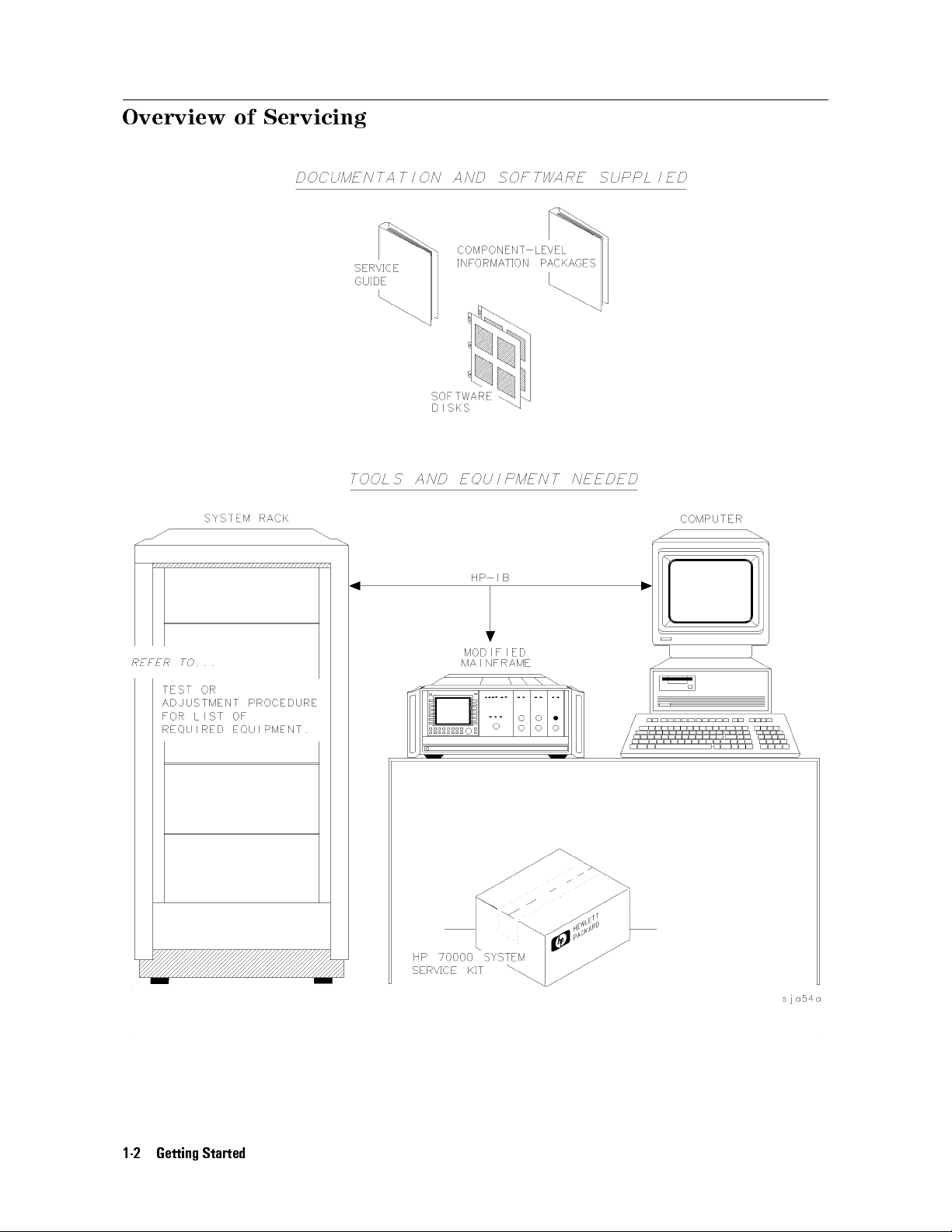
Overview of Servicing ............................ 1-2
Contacting Hewlett-Packard for Servicing or Ordering Parts ...... .... 1-6
2. Installing and Conguring Module Verication Software
Computer Software Requirements .. ...... ...... ...... .. 2-2
Computer Hardware Requirements ...... ...... ..... ..... 2-3
Installing Software and Creating Working Copies . . . . . . . . . . . . . . . . 2-5
Conguring Module Verication Software .... ...... ...... ... 2-11
Working with the
Working with the
TSCRIPT
MS_TABLE
File . . . . . . . . . . . . . . . . . . . . . . . . 2-16
Data File . . . . . . . . . . . . . . . . . . . . .
3. Running Module Verication Software
Loading from an SRM or HFS Hard Disk . . . . . . . . . . . . . . . . . . . .
Entering Information About Your RF Section (UUT) ...... ...... ..
Running from the Main Test Menu ......................
Working with the Calibration Editor .....................
4. Test Equipment and Calibrations
Test Equipment Requirements ........................
Test Equipment Calibrations .........................
Spectrum Analyzer Calibration ........................
Flatness Calibration ...... ...... ...... ...... .....
External Frequency Reference Requirements .................
2-23
3-2
3-3
3-10
3-12
4-2
4-5
4-6
4-7
4-9
5. Adjustment Procedures
Before You Begin Adjustments .. ...... ...... ...... .... 5-2
Overall Adjustment Setup .......... ...... ...... .... 5-4
Adjustment 01. Power Supply Voltage Checks . . . . . . . . . . . . . . . . . 5-5
Adjustment 02. 1st LO Power . . . . . . . . . . . . . . . . . . . . . . . . . 5-7
2nd Converter Adjustments . . . . . . . . . . . . . . . . . . . . . . . . . . 5-10
Adjustment 03.01 VCO Tune-Line Voltage ...................
Adjustment 03.02 VCO Frequency and Amplitude ...............
Adjustment 03.03 2nd Converter LO Feedthrough .. ...... ...... .
Adjustment 03.04 Sampler DC IF Out .....................
Adjustment 03.05 Sampler AC IF Out .... ...... ...... .....
Adjustment 03.06 Search Oscillator Duty Cycle and Period .... ...... . 5-21
Adjustment 03.07 Search Oscillator Square Wave Min/Max .. ...... ... 5-23
Adjustment 03.08 Search Oscillator VCO Tune Line .............. 5-25
Adjustment 03.09 Phase Lock . . . . . . . . . . . . . . . . . . . . . . . . . 5-27
Adjustment 03.10 VCO Tune Range . . . . . . . . . . . . . . . . . . . . . . 5-29
Adjustment 03.11 Lock Range Measurement . . . . . . . . . . . . . . . . . .
Adjustment 03.12 Bandpass Filter and VCO Tune Range Final . . . . . . . . . .
Adjustment 03.13 Mixer Bias . . . . . . . . . . . . . . . . . . . . . . . . .
Adjustment 04. Last Converter Alignment . . . . . . . . . . . . . . . . . . .
Adjustment 05. PGA Calibration .......................
5-11
5-13
5-15
5-17
5-19
5-32
5-34
5-37
5-39
5-44
Contents-1

Adjustment 06. YTF Alignment . . . . . . . . . . . . . . . . . . . . . . . . 5-46
6. Verication Tests
Before You Begin Testing . . . . . . . . . . . . . . . . . . . . . . . . . . . 6-2
Overall Test Setup . . . . . . . . . . . . . . . . . . . . . . . . . . . . . . 6-4
Test 01. Switch Repeatability - HP 70910A Only . . . . . . . . . . . . . . . . 6-5
Test 02. External Mixer Gain Calibration ................... 6-7
Test 03. Gain and Flatness Calibration .................... 6-9
Test 04. Flatness Below 50 MHz ....................... 6-11
Test 05. Microwave Gain and Noise Figure .... ...... ...... .. 6-13
Test 06. External Mixer Noise Figure ..................... 6-17
Test 07. Microwave TOI ........................... 6-19
Test 08. Diagnostics Check . . . . . . . . . . . . . . . . . . . . . . . . . . 6-22
Test 09. Front Panel LEDs Check . . . . . . . . . . . . . . . . . . . . . . . 6-24
Test 10. 21.4 MHz IF Output Response .................... 6-25
Test 11. IF Emissions and Harmonics .. ...... ..... ...... .. 6-27
Test 12. EMIM LO Out Power and Harmonics ................. 6-29
Test 13. 1st LO Out Power and Harmonics . . . . . . . . . . . . . . . . . . . 6-31
Test 14. TUNE+SPAN+PRESEL PEAK Output .. ...... ...... .. 6-33
Test 15. LO Input Amplitude Range . . . . . . . . . . . . . . . . . . . . . . 6-35
Test 16. Microwave Image Rejection .....................
Test 17. EMIM Image Rejection . . . . . . . . . . . . . . . . . . . . . . . .
Test 18. 2nd Converter Startup . . . . . . . . . . . . . . . . . . . . . . . .
Test 19. Microwave Residual Responses . . . . . . . . . . . . . . . . . . . .
Test 20. Microwave In-Range Multiples ...... ...... ...... ..
Test 21. 321.4 MHz IF Output Bandwidth - HP 70910A Only
..........
6-37
6-39
6-41
6-43
6-45
6-47
7. Troubleshooting
Preparing a Static-Safe Work Station .... ...... ...... .....
Power-On Failures . . . . . . . . . . . . . . . . . . . . . . . . . . . . . .
Display Problems .......... ...... ..... ...... ...
Mainframe Problems . . . . . . . . . . . . . . . . . . . . . . . . . . . . .
Communication Problems on the HP-MSIB I/O . . . . . . . . . . . . . . . . .
Error Messages .......... ...... ...... ..... ....
Adjustment Problems ............................
Verication Test Problems .......................... 7-23
Troubleshooting the A2 RF First Converter ........ ...... .... 7-30
Troubleshooting the A5, A7, A8, A9 Second Converter . . . . . . . . . . . . . 7-31
Troubleshooting the A6 Programmable Gain Amplier ............. 7-34
Troubleshooting the A10 Last Converter ................... 7-36
Troubleshooting the A11 5 dB Step Attenuator .. ...... ...... ..
Troubleshooting the A12 RF Switch/A15 RF Switch and A21 Pin Switch/Diplexer
Troubleshooting the A14 YTF and A19 Power Supply/YTF Driver . . . . . . . .
Troubleshooting the A16 Preamp/Mixer . . . . . . . . . . . . . . . . . . . .
Troubleshooting the A18 LO Leveling Amplier .... ...... ...... 7-44
Troubleshooting the A20 Controller . . . . . . . . . . . . . . . . . . . . . .
Performing Related Adjustments and Verication Tests . . . . . . . . . . . . . 7-47
Troubleshooting Utilities Menu ........................
Overall Block Diagram of HP 70909A or HP 70910A RF section . . . . . . . . . 7-53
7-2
7-4
7-5
7-9
7-10
7-13
7-17
7-38
7-39
7-40
7-43
7-45
7-50
Contents-2
8. Replacing Major Assemblies
Module Cover .. ...... ...... ..... ...... ...... . 8-2
Front Panel ................................. 8-4
Rear Panel ................................. 8-6
A2 RF First Converter ............................ 8-8
A5, A7, A8, A9 Second Converter ...................... 8-10
A6 Programmable Gain Amplier . . . . . . . . . . . . . . . . . . . . . . . 8-12
A10 Last Converter ............................. 8-14
A11 5 dB Step Attenuator .......................... 8-16
A12 RF Switch/A15 RF Switch (HP 70910A RF Section Only) . . . . . . . . . . 8-18
A14 YTF .................................. 8-20
A16 Preamp/Mixer . . . . . . . . . . . . . . . . . . . . . . . . . . . . . . 8-22
A18 LO Leveling Amplier . . . . . . . . . . . . . . . . . . . . . . . . . . 8-24
A19 Power Supply/YTF Driver Service Position ...... ...... .... 8-26
A19 Power Supply/YTF Driver ........................ 8-28
A20 Controller . . . . . . . . . . . . . . . . . . . . . . . . . . . . . . . . 8-30
A22 Status ................................. 8-32
9. Overall Parts Identication Drawings
Major Cables and Assemblies . . . . . . . . . . . . . . . . . . . . . . . . . 9-2
Front View Identication . . . . . . . . . . . . . . . . . . . . . . . . . . .
Right Side View Identication .... ...... ...... ...... ..
Left Side View Identication, Exploded . . . . . . . . . . . . . . . . . . . .
Rear View Identication ...........................
9-8
9-9
9-14
9-16
Index
Contents-3
Figures
1-1. Typical Serial Number Label .... ...... ...... ..... ... 1-6
3-1. Typical Serial Number Label .... ...... ...... ..... ... 3-3
4-1. Spectrum Analyzer Calibration Setup . . . . . . . . . . . . . . . . . . . . 4-6
4-2. Flatness Calibration and Verication Test Setup ........ ..... .. 4-7
4-3. Frequency Reference Connections, Using an HP 70310A Precision Frequency
Reference ............................... 4-10
4-4. Frequency Reference Connections, Using the HP 8566B Spectrum Analyzer . . 4-11
5-1. Adjustments Equipment Matrix . . . . . . . . . . . . . . . . . . . . . . . 5-2
5-2. Overall Adjustment Equipment Setup . . . . . . . . . . . . . . . . . . . . 5-4
5-3. Equipment Setup for Adjustment 01. Power Supply Voltage Checks . . . . . . 5-5
5-4. Location of A19J8-1 . . . . . . . . . . . . . . . . . . . . . . . . . . . . 5-6
5-5. Equipment Setup for Adjustment 02. 1st LO Power .............
5-6. Side View Location of Adjustment 02. 1st LO Power . . . . . . . . . . . . .
5-7. PROTECT/ENABLE Switch Location ....................
5-8. 2nd Converter Adjustment Locations .. ...... ...... ......
5-9. 2nd Converter Adjustment Locations .. ...... ...... ......
5-10. Equipment Setup for Adjustment 03.01 VCO Tune-Line Voltage . . . . . . . .
5-11. Locations for Adjustment 03.01 VCO Tune-Line Voltage ...........
5-12. Equipment Setup for Adjustment 03.02 VCO Frequency and Amplitude . . . . 5-13
5-13. Locations for Adjustment 03.02 VCO Frequency and Amplitude . . . . . . . .
5-14. Equipment Setup for Adjustment 03.03 2nd Converter LO Feedthrough . . . . 5-15
5-15. Locations for Adjustment 03.03 2nd Converter LO Feedthrough . . . . . . . . 5-15
5-16. Equipment Setup for Adjustment 03.04 Sampler DC IF Out . . . . . . . . . .
5-17. Locations for Adjustment 03.04 Sampler DC IF Out .............
5-18. Equipment Setup for Adjustment 03.05 Sampler ACIFOut..........
5-19. Locations for Adjustment 03.05 Sampler AC IF Out ........ .....
5-20. Equipment Setup for Adjustment 03.06 Search Oscillator Duty Cycle and Period 5-21
5-21. Locations for Adjustment 03.06 Search Oscillator Duty Cycle and Period ... 5-21
5-22. Equipment Setup for Adjustment 03.07 Search Oscillator Square Wave Min/Max 5-23
5-23. Locations for Adjustment 03.07 Search Oscillator Square Wave Min/Max . . . . 5-23
5-24. Equipment Setup for Adjustment 03.08 Search Oscillator VCO Tune Line ... 5-25
5-25. Locations for Adjustment 03.08 Search Oscillator VCO Tune Line . . . . . . .
5-26. Equipment Setup for Adjustment 03.09 Phase Lock ........ .....
5-27. Locations for Adjustment 03.09 Phase Lock .................
5-28. Equipment Setup for Adjustment 03.10 VCO Tune Range . . . . . . . . . . . 5-29
5-29. Locations for Adjustment 03.10 VCO Tune Range .... ...... .... 5-29
5-30. Equipment Setup for Adjustment 03.11 Lock Range Measurement ...... 5-32
5-31. Locations for Adjustment 03.11 Lock Range Measurement ...... .... 5-32
5-32. Equipment Setup for Adjustment 03.12 Bandpass Filter and VCO Tune Range
Final ................................. 5-34
5-33. Locations for Bandpass Filter Tune Range and VCO Tune Range ...... . 5-35
5-34. Equipment Setup for Adjustment 03.13 Mixer Bias . . . . . . . . . . . . . . 5-37
5-35. Locations for Adjustment 03.13 Mixer Bias .................
5-36. Equipment Setup for Adjustment 04. Last Converter Alignment ....... 5-39
5-37. Locations for Adjustment 04. Last Converter Alignment ...........
5-38. Equipment Setup for Adjustment 05. PGA Calibration . . . . . . . . . . . .
5-7
5-7
5-9
5-10
5-10
5-11
5-11
5-13
5-17
5-17
5-19
5-19
5-25
5-27
5-27
5-37
5-40
5-44
Contents-4

5-39. Equipment Setup for Adjustment 06. YTF Alignment ...... ...... 5-46
5-40. A19 OFFSET (R38) and GAIN (R39) Adjustments . . . . . . . . . . . . . . . 5-48
6-1. Verication Tests Equipment Matrix . . . . . . . . . . . . . . . . . . . . . 6-2
6-2. Overall RF Section Verication Test Setup . . . . . . . . . . . . . . . . . . 6-4
6-3. Equipment Setup for Test 01. Switch Repeatability - HP 70910A Only . . . . . 6-5
6-4. Equipment Setup for Test 02. External Mixer Gain Calibration Test Setup . . . 6-7
6-5. Equipment Setup for Test 03. Gain and Flatness Calibration ........ . 6-9
6-6. Equipment Setup for Test 04. Flatness Below 50 MHz .. ...... .... 6-11
6-7. Equipment Setup for Noise Figure Calibration . . . . . . . . . . . . . . . . 6-13
6-8. Equipment Setup for Gain Calibration and Measurement . . . . . . . . . . . 6-14
6-9. Equipment Setup for Test 06. External Mixer Noise Figure . . . . . . . . . . 6-17
6-10. Equipment Setup for Test 07. Microwave TOI .... ...... ...... 6-19
6-11. Equipment Setup for Test 08. Diagnostics Check . . . . . . . . . . . . . . . 6-22
6-12. Equipment Setup for Test 09. Front Panel LEDs Check . . . . . . . . . . . . 6-24
6-13. Equipment Setup for Test 10. 21.4 MHz IF Output Response ........ . 6-25
6-14. Equipment Setup for Test 11. IF Emissions and Harmonics . . . . . . . . . . 6-27
6-15. Equipment Setup for Test 12. EMIM LO Out Power and Harmonics .. .... 6-29
6-16. Equipment Setup for Test 13. 1st LO Out Power and Harmonics ...... . 6-31
6-17. Equipment Setup for Test 14. TUNE+SPAN+PRESEL PEAK Output ..... 6-33
6-18. Equipment Setup for Test 15. LO Input Amplitude Range .... ...... 6-35
6-19. Equipment Setup for Test 16. Microwave Image Rejection ..........
6-20. Equipment Setup for Test 17. EMIM Image Rejection . . . . . . . . . . . . .
6-21. Equipment Setup for Test 18. 2nd Converter Startup ............
6-22. Equipment Setup for Test 19. Microwave Residual Responses . . . . . . . . .
6-23. Equipment Setup for Test 20. Microwave In-Range Multiples . . . . . . . . .
6-24. Equipment Setup for Test 21. 321.4 MHz IF Output Bandwidth . . . . . . . .
7-1. Static-Safe Work Station .. ...... ...... ...... ......
7-2. Line Voltage Selector . . . . . . . . . . . . . . . . . . . . . . . . . . . .
7-3. Line Fuse Removal and Replacement ....................
NNNNNNNNNNNNNNNNNNNNNNNNNNNNNNNNNNNNNNNNN
7-4.
display tests
Menu Keys ........................
7-5. Condence Test ..............................
7-6. Overall Block Diagram of HP 70909A or HP 70910A RF section . . . . . . . .
8-1. Module Cover Removal/Replacement ....................
8-2. Front Panel Removal/Replacement .....................
8-3. Rear Panel Removal/Replacement . . . . . . . . . . . . . . . . . . . . . .
6-37
6-39
6-41
6-43
6-45
6-47
7-2
7-5
7-5
7-7
7-8
7-53
8-3
8-5
8-7
8-4. A2 RF First Converter Removal/Replacement ................ 8-9
8-5. A5, A7, A8, A9 Second Converter Removal/Replacement . . . . . . . . . . . 8-11
8-6. A6 Programmable Gain Amplier Removal/Replacement .... ...... . 8-13
8-7. A10 Last Converter Removal/Replacement .. ...... ...... ... 8-15
8-8. A11 5 dB Step Attenuator Removal/Replacement .............. 8-17
8-9. A12 RF Switch/A15 RF Switch Removal/Replacement ............
8-10. A14 YTF Removal/Replacement . . . . . . . . . . . . . . . . . . . . . . .
8-11. A16 Preamp/Mixer Removal/Replacement . . . . . . . . . . . . . . . . . .
8-19
8-21
8-23
8-12. A18 LO Leveling Amplier Removal/Replacement .............. 8-25
8-13. A19 Power Supply/YTF Driver Service Position ............... 8-27
8-14. A19 Power Supply/YTF Driver Removal/Replacement ............ 8-29
8-15. A20 Controller Removal/Replacement . . . . . . . . . . . . . . . . . . . .
8-16. A22 Status Removal/Replacement . . . . . . . . . . . . . . . . . . . . . .
8-31
8-33
9-1. Overall Parts Identication Drawing, Major Cables (1 of 4) .......... 9-4
9-2. Overall Parts Identication Drawing, Major Cables (2 of 4) .......... 9-5
9-3. Overall Parts Identication Drawing, Major Cables (3 of 4)
9-4. Overall Parts Identication Drawing, Major Cables (4 of 4)
..........
..........
9-5. Overall Parts Identication Drawing, Front View ..............
9-6. Overall Parts Identication Drawing, Right Side View (1 of 4) . . . . . . . . .
9-7. Overall Parts Identication Drawing, Right Side View (2 of 4) . . . . . . . . .
9-6
9-7
9-8
9-10
9-11
Contents-5

9-8. Overall Parts Identication Drawing, Right Side View, Exploded (3 of 4) . . . . 9-12
9-9. Overall Parts Identication Drawing, Right Side View, Exploded (4 of 4) . . . . 9-13
9-10. Overall Parts Identication Drawing, Left Side View, Exploded . . . . . . . . 9-15
9-11. Overall Parts Identication Drawing, Rear View . . . . . . . . . . . . . . . 9-16
Contents-6
Tables
1-1. HP Service Centers ...... ...... ...... ...... .... 1-7
1-2. Packaging for a 2/8 Module (RF Section) . . . . . . . . . . . . . . . . . . . 1-9
7-1. Static-Safe ESD Accessories ...... ...... ..... ...... . 7-3
7-2. Default HP-MSIB Address Map ....................... 7-11
7-3. A11 5 dB Step Attenuator Logic ...................... 7-38
9-1. Cables for the HP 70909A RF Section and HP 70910A RF Section . . . . . . . 9-2
9-2. Assemblies for the HP 70909A RF Section and HP 70910A RF Section . . . . . 9-3
9-3. Overall Parts Identication Listing, Front View ........ ...... . 9-8
9-4. Overall Parts Identication Listing, Right Side View ........ ..... 9-9
9-5. Overall Parts Identication Listing, Left Side View Exploded . . . . . . . . . 9-14
9-6. Overall Parts Identication Listing, Rear View . . . . . . . . . . . . . . . . 9-16
Contents-7

Getting Started
1
Overview
In this chapter you will learn about:
Various types of test software available for your RF section
The organization of this service guide and component-level repair
information
How to contact Hewlett-Packard for servicing or ordering parts
This chapter introduces you to servicing and the various types of test software available for
your RF section. You will rst learn how the service guide and the component-level repair
information (CLIP set) are organized, and then you'll learn how to contact Hewlett-P
ackard for
servicing or ordering replacement parts.
When is Servicing Needed?
Servicing is needed:
if error messages are displayed on your HP 70000 Series display
if an ERROR LED or FAULT LED is on
or, to perform repairs or adjustments or both
If you determine that your RF section needs servicing, you can return your RF section to
a Hewlett-Packard service center, or you can perform the servicing yourself using module
verication software and the information in this service guide
To perform the servicing yourself using module verication software
.
, review the rest of the
information in this chapter, and then proceed to Chapter 2 where you will learn how to install
and congure module verication software.To return your RF section to a Hewlett-Packard
service center for service, refer to \Contacting Hewlett-Packard for Servicing or Ordering
Parts".
Overview of Servicing
:::::: ::::::: :::::: ::::::: ::::::: :::::: ::::::: ::::::: :::::: ::::::: ::::::
Contacting Hewlett-Packard for Servicing or Ordering Parts
::::: ::::::: :::::: ::::::: :::::::
Getting Started 1-1
1-2
1-6
Overview of Servicing
1-2 Getting Started
Overview of Servicing
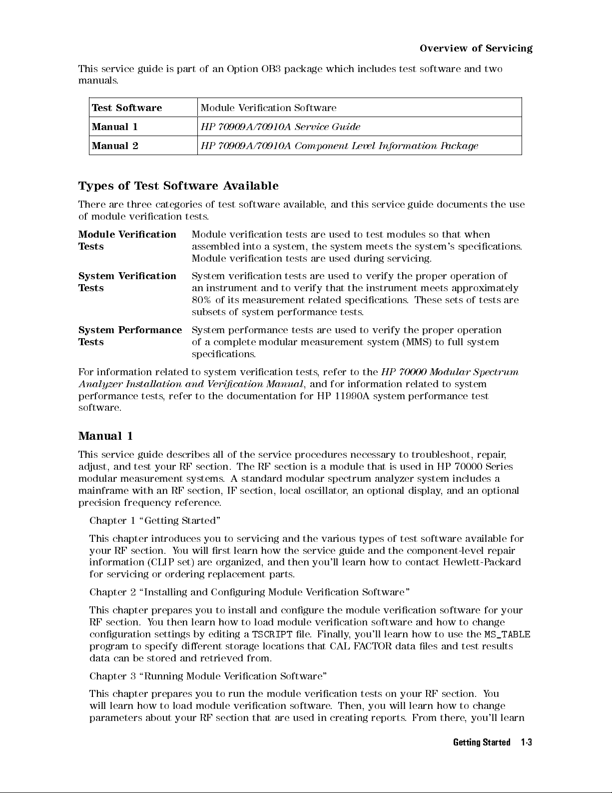
This service guide is part of an Option OB3 package which includes test software and two
manuals.
Test Software
Manual 1
Manual 2
Module Verication Software
HP 70909A/70910A Service Guide
HP 70909A/70910A Component Level Information Package
Types of Test Software Available
There are three categories of test software available, and this service guide documents the use
of module verication tests.
Module Verication
Tests
Module verication tests are used to test modules so that when
assembled into a system, the system meets the system's specications.
Module verication tests are used during servicing.
System Verication
Tests
System verication tests are used to verify the proper operation of
an instrument and to verify that the instrument meets approximately
80% of its measurement related specications
. These sets of tests are
subsets of system performance tests.
System Performance
Tests
System performance tests are used to verify the proper operation
of a complete modular measurement system (MMS) to full system
specications.
For information related to system verication tests, refer to the
Analyzer Installation and Verication Manual
, and for information related to system
HP 70000 Modular Spectrum
performance tests, refer to the documentation for HP 11990A system performance test
software.
Manual 1
This service guide describes all of the service procedures necessary to troubleshoot, repair
,
adjust, and test your RF section . The RF section is a module that is used in HP 70000 Series
modular measurement systems. A standard modular spectrum analyzer system includes a
mainframe with an RF section , IF section , local oscillator, an optional display, and an optional
precision frequency reference.
Chapter 1 \Getting Started"
This chapter introduces you to servicing and the various types of test software available for
your RF section. You will rst learn how the service guide and the component-level repair
information (CLIP set) are organized, and then you'll learn how to contact Hewlett-P
ackard
for servicing or ordering replacement parts.
Chapter 2 \Installing and Conguring Module Verication Software "
This chapter prepares you to install and congure the module verication software for your
RF section. You then learn how to load module verication software and how to change
conguration settings by editing a
TSCRIPT
le. Finally, you'll learn how to use the
MS_TABLE
program to specify dierent storage locations that CAL FACTOR data les and test results
data can be stored and retrieved from.
Chapter 3 \Running Module Verication Software"
This chapter prepares you to run the module verication tests on your RF section. Y
will learn how to load module verication software
parameters about your RF section that are used in creating reports
. Then, you will learn how to change
. From there, you'll learn
ou
Getting Started 1-3

Overview of Servicing
how to run the module verication software tests, and nally, you'll learn how to create,
edit, print, or purge a CAL FACTOR data le using the Calibration Editor program.
Chapter 4 \Test Equipment and Calibrations"
This chapter contains the test equipment setups for all calibration procedures that must
be performed in order to optimize module performance when assemblies are changed,
repaired, or adjusted. You will learn about the requirements as well as when and how often
calibrations are required. Finally, you'll learn about the requirements for the external
frequency reference being used.
Chapter 5 \Adjustment Procedures"
This chapter contains the test equipment setups for all adjustment procedures that are used
to optimize module performance when assemblies are changed, repaired, or adjusted. All of
the setups described in this chapter are automated and require a controller running module
verication software.
Chapter 6 \Verication Tests"
This chapter contains the test equipment setups for all module verication tests that are
used to optimize module performance when assemblies are changed, repaired, or adjusted.
All of the setups described in this chapter are automated and require a controller running
module verication software.
Chapter 7 \Troubleshooting"
This chapter prepares you for troubleshooting your RF section. Y
ou will learn how to prepare
a static-safe work station that is used during servicing. Then, you will learn how to resolve
power-on problems, adjustment problems, and verication test problems. Finally, you'll
learn in-depth circuit troubleshooting as well as which adjustments and verication tests
have to be run to ensure proper operation after an assembly has been repaired, replaced, or
adjusted.
Chapter 8 \Replacing Major Assemblies"
This chapter contains procedures for removal and replacement of major assemblies in your
RF section.
Chapter 9 \Overall Parts Identication Drawings"
This chapter contains information on all overall parts identication drawings that should be
used when performing the troubleshooting procedures described in this service guide.
Index
An index is also added at the end of this service guide to aid the user in nding key items of
interest.
Manual 2
Manual 2 is a separate volume that contains packets of component-level repair information
for each RF section board assembly that has eld-replaceable parts. Each packet includes the
parts list, component-location drawing, and schematics for a specic board-assembly part
number. Manual 2 also contains a table that can be used to cross reference dierent board
assemblies that have dierent serial prex breaks.
1-4 Getting Started
Information Not Covered in Manual 1 or 2
Overview of Servicing
System congurations are documented in the
Installation and Verication Manual
Guide
.
Error codes not covered in the troubleshooting chapter of this manual (Chapter 7) may be
found in the
HP 71910P Wide-Bandwidth Receiver User's Guide
guides.
Each modular measurement system (MMS) module has its own service guide.For further
information related to the servicing of additional and alternate modules that can be used in
this system, refer to each module's service guide.
Before You Begin Servicing
Review the Troubleshooting sections of Chapter 7 as well as the directions for \Installing and
Conguring Test and Adjustment Software" in Chapter 2.
HP 70000 Modular Spectrum Analyzer Installation and Verication Manual
and
HP 70000 Modular Spectrum Analyzer
HP 71910P Wide-Bandwidth Receiver User's
, and additional module specic service
,
Getting Started 1-5

Contacting Hewlett-Packard for Servicing or Ordering Parts
Contact Hewlett-Packard for service or ordering parts.
Service Before calling Hewlett-Packard or returning your RF section for service, please
read your warranty information. Warranty information is printed at the front
of this service guide.
Ordering Parts To order parts, contact the HP Service Center closest to you.
In any correspondence or telephone conversations, refer to the RF section by its full model
number and full serial number. With this information, the Hewlett-Packard representative can
determine whether your unit is still within its warranty period.
Determining Your RF Section's Serial Number
When a module is manufactured by Hewlett-Packard, it is given a unique serial number. This
serial number is attached to a label on the front frame or front panel of the module. A serial
number label is in two parts. (Refer to Figure 1-1.) The rst part makes up the serial number
prex and consists of four digits and a letter. The second part makes up the serial number
sux and consists of the last ve digits on the serial number label. The serial number prex is
the same for all identical modules; it only changes when a change in the electrical or physical
functionality is made. The serial number sux, however, changes sequentially and is dierent
for each module.
1-6 Getting Started
Figure 1-1. Typical Serial Number Label

Contacting Hewlett-Packard for Servicing or Ordering Parts
A current list of Hewlett-Packard Service Centers can be accessed on the Internet at:
http://www.tmo.hp.com/tmo/contacts/
If you do not have access to the Internet, one of the following Hewlett-Packard locations can
direct you to your nearest Hewlett-Packard representative:
Table 1-1. HP Service Centers
United States
Canada
Europe
Japan
Latin America
Austrailia/New
Zealand
Asia-Pacic
Hewlett-Packard Company
Test and Measurement Call Center
(800) 403-0801
(800) 857-8161 (FAX)
Hewlett-Packard Canada Ltd.
5150 Spectrum Way
Mississauga, Ontario L4W 5G1
(905) 206-4725
(905) 206-4739 (FAX)
Hewlett-Packard European Marketing Centre
Postbox 667
1180 AR Arnstelveen
Netherlands
(31/20) 547-6669
(31/20) 647-8706
Hewlett-Packard Japan Ltd.
27-15, Yabe 1-Chome,
Sagamihara, Kanagawa 229
Japan
(81426) 567 832
(81426) 567 843 (FAX)
Hewlett-Packard Latin America Region Headquarters
5200 Blue Lagoon Drive, 9th Floor
Miami, Florida 33126
U.S.A.
(305) 267 4245
(305) 267 4288 (FAX)
Hewlett-Packard Calibration Services Austrailia Ltd.
31-41 Joseph Street
Blackburn, Victoria 3130
Austrailia
1800 802 540
1800 681 776 (FAX)
Hewlett-Packard Asia-Pacic Ltd.
17-21/F Shell Tower, Times Square
1 Matheson Street, Causeway Bay
Hong Kong
(852) 25 997 777
(852) 25 069 261 (FAX)
Getting Started 1-7

Contacting Hewlett-Packard for Servicing or Ordering Parts
Returning Your RF Section for Service
Hewlett-Packard has sales and service oces around the world to provide complete support for
your RF section. To obtain servicing information or to order replacement parts, contact the
nearest Hewlett-Packard sales and service oce listed in Table 1-1.
Use the following procedure to return your RF section to Hewlett-Packard for service:
1. Fill out a service tag (available at the end of this service guide) and attach it to the
instrument. Please be as specic as possible about the nature of the problem. Send a copy
of any or all of the following information:
any error messages that appeared on the HP 70000 Series display
a completed Performance Test record
any other specic data on the performance of the RF section
CAUTION
Damage can result if the original packaging materials are not used. Packaging
materials should be anti-static and should cushion the RF section on all sides.
Never use styrene pellets in any shape as packaging materials. They do not
adequately cushion the instrument or prevent it from moving in the shipping
container. Styrene pellets can also cause equipment damage by generating
static electricity or by lodging in fan motors.
2. Place the RF section in its original packaging materials
.
If the original packaging materials are not available, you can contact a Hewlett-Packard
sales and service oce to obtain information on packaging materials or you may use an
alternative packing material referred to as \bubble-pack". One of the companies that makes
bubble-pack is Sealed Air Corporation of Hayward, California, 94545.
3. Surround the RF section with at least 3 to 4 inches of its original packing material or
bubble-pack to prevent the RF section from moving in its shipping container
.
4. Place the RF section, after wrapping it with packing material, in its original shipping
container or a strong shipping container that is made of double-walled corrugated cardboard
with 159 kg (350 lb) bursting strength.
The shipping container must be both large enough and strong enough to accommodate your
RF section and allow at least 3 to 4 inches on all sides for packing material.
5. Seal the shipping container securely with strong nylon adhesive tape.
6. Mark the shipping container \FRAGILE, HANDLE WITH CARE" to help ensure careful
handling.
7. Retain copies of all shipping papers.
1-8 Getting Started
Contacting Hewlett-Packard for Servicing or Ordering Parts
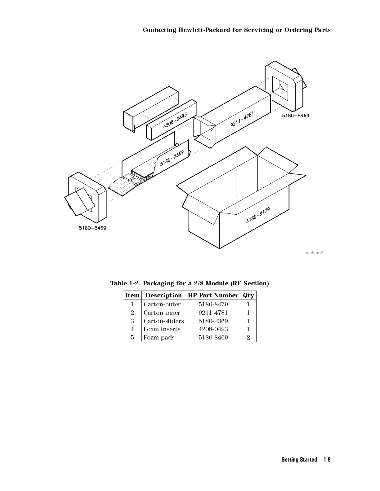
Table 1-2. Packaging for a 2/8 Module (RF Section)
Item Description HP Part Number Qty
1 Carton-outer 5180-8479 1
2 Carton-inner 9211-4781 1
3 Carton-sliders 5180-2369 1
4 Foam inserts 4208-0493 1
5 Foam pads 5180-8469 2
Getting Started 1-9

Installing and Conguring
Module Verication Software
2
Overview
In this chapter you will learn about:
Computer software and hardware requirements
Keyboard compatibility
Installing module verication software, TSCRIPT, and MS TABLE
Purging module verication software, TSCRIPT, and MS TABLE
Test equipment requirements including default models and HP-IB addresses
Editing the
TSCRIPT
le
Specifying storage locations for CAL FACTOR data les and test result data
This chapter prepares you to install and congure the module verication software for your
RF section. You then learn how to load module verication software and how to change
conguration settings by editing a
program to specify dierent storage locations where CAL F
TSCRIPT
le. Finally, you'll learn how to use the
ACTOR data les and test results
MS_TABLE
data can be stored and retrieved from.
Computer Software Requirements
Computer Hardware Requirements
Installing Software and Creating Working Copies
Conguring Module Verication Software
Working with the
Working with the
TSCRIPT
MS_TABLE
File
::::::: ::::::: :::::: ::::::: ::::::: :::::: ::::::: ::::::: ::::::
::::: ::::::: ::::::: :::::: ::::::: ::::::: :::::: ::::::: :::::::
:::::: ::::::: :::::: ::::::: ::::::: :::::: :::::
::::::: ::::::: ::::::: :::::: ::::::: ::::::: :::::: ::::
:::::: ::::::: ::::::: :::::: ::::::: ::::::: :::::: ::::::: ::::::: :
Data File
::::::: ::::::: :::::: ::::::: ::::::: :::::: ::::::: :::::::
2-2
2-3
2-5
2-11
2-16
2-23
Installing and Conguring Module Verication Software 2-1
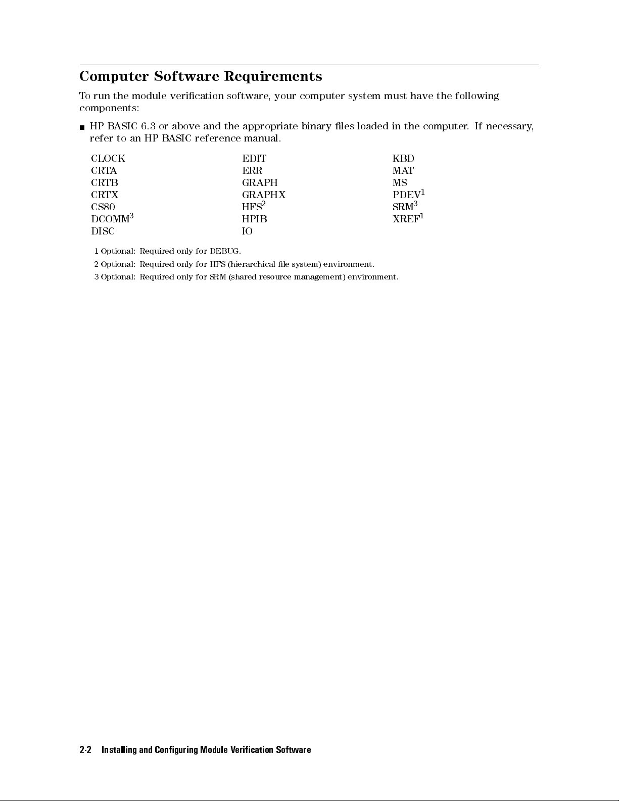
Computer Software Requirements
To run the module verication software, your computer system must have the following
components:
HP BASIC 6.3 or above and the appropriate binary les loaded in the computer. If necessary,
refer to an HP BASIC reference manual.
CLOCK EDIT KBD
CRTA ERR MAT
CRTB GRAPH MS
CRTX GRAPHX PDEV
CS80 HFS
DCOMM
DISC IO
1
2
3
3
Optional: Required only for DEBUG.
Optional: Required only for HFS (hierarchical le system) environment.
Optional: Required only for SRM (shared resource management) environment.
2
HPIB XREF
SRM
1
3
1
2-2 Installing and Conguring Module Verication Software
Computer Hardware Requirements
Computer Hardware Requirements
To run the module verication software, your computer system must have the following:
Computer HP 9000 Series 300 controller
HP BASIC HP BASIC 6.3 or above and the appropriate binary les loaded
RAM 8 MB of RAM
Interface One HP-IB interface
Hard Disk SRM or HFS hard disk with 5 MB available space
Floppy Disk Dual or single 3.5 inch double-sided double-density 720 KB oppy disk drives
Computer Keyboard Compatibility and Mouse Operation
The instructions in this service guide are based on an HP 9000 Series 300 controller with an
HP 46021A keyboard. The module verication software supports several input devices; it will
detect the keyboard you are using and will display the appropriate key commands. However,
keystrokes and text dierences may appear in the softkeys and menus displayed on screen. If
you are using an HP 98203C keyboard, refer to the section \Using an HP 98203C Keyboard
with a Series 300 Computer".
Using an HP 46021A Keyboard with a Series 300 Computer
If you use an HP 46021A keyboard (ITF keyboard) with a Series 300 computer
verication software assumes you have a mouse or a track ball.
To highlight your preference, press the
To choose the highlighted item, press
press
4
5
.
Return
To exit the menu, press
4
5
.
4
5or4
5
keys.
9
5
.To save your choice and return to the menu,
4
Select
8
, the module
Installing and Conguring Module Verication Software 2-3
Computer Hardware Requirements
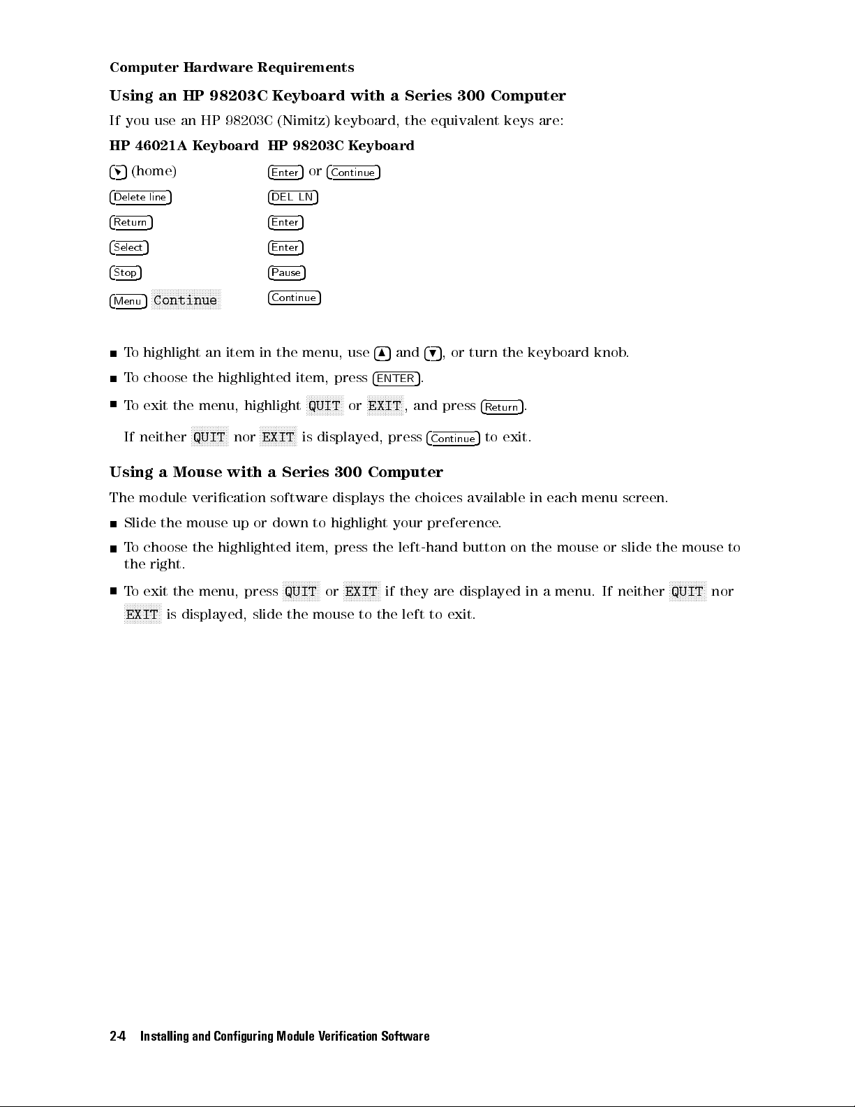
Using an HP 98203C Keyboard with a Series 300 Computer
If you use an HP 98203C (Nimitz) keyboard, the equivalent keys are:
HP 46021A Keyboard HP 98203C Keyboard
45
(home)
4
Enter
5or4
Continue
5
4
Delete line
4
Return
4
Select
4
Stop
4
Menu
5 4
5 4
5 4
5 4
NNNNNNNNNNNNNNNNNNNNNNNNNN
5
Continue
4
DEL LN
5
Enter
5
Enter
5
Pause
Continue
5
5
To highlight an item in the menu, use
To choose the highlighted item, press
NNNNNNNNNNNNN
To exit the menu, highlight
If neither
NNNNNNNNNNNNNN
QUIT
nor
NNNNNNNNNNNNNN
EXIT
N
QUIT
or
is displayed, press
485
4
ENTER
NNNNNNNNNNNNN
N
EXIT
and
495
, or turn the keyboard knob.
5
.
, and press
4
Continue
4
Return
5
to exit.
5
.
Using a Mouse with a Series 300 Computer
The module verication software displays the choices available in each menu screen.
Slide the mouse up or down to highlight your preference
.
To choose the highlighted item, press the left-hand button on the mouse or slide the mouse to
the right.
To exit the menu, press
NNNNNNNNNNNNNN
EXIT
is displayed, slide the mouse to the left to exit.
NNNNNNNNNNNNNN
QUIT
or
NNNNNNNNNNNNNN
EXIT
if they are displayed in a menu. If neither
NNNNNNNNNNNNNN
QUIT
nor
2-4 Installing and Conguring Module Verication Software

Installing Software and Creating Working Copies
Installing Software and Creating Working Copies
Overview
In this section you will perform the following steps:
Run INSTALL, from a oppy disk drive or other logical device, and create a
working copy.
The INSTALL program performs the following:
a. Assigns a source disk drive (and optional directory)
b. Assigns a destination disk drive (and optional directory)
c. Copies source les to the destination disk drive (and optional directory)
Module verication software for the RF section consists of the following les:
Executive Disk 1 Executive Disk 2 Tests Disk
OPV UT_SUBS D_8757 DIAGNOSTIC MW_IMGRJT
CSUBS UT_SUBS0 D_3456 EM_IMGRJT EMGAINCAL
CSUBS6 TSCRIPT D_3457 FLAT_50MH AMP_ADJUST
CSUBS63_UX TSCRIPT.MS D_436 LED_CHECK LAST_CONV
CSUBS64_UX TESTINFO D_438 MW_MULT PGA_CALIB
CSUBS7_UX OPTIONS D_8970 MWNOISEFIG 2ND_CONV
INSTALL MUT_INFO D_8566 MW_RESID PS_CHECK
COM ADDR_DEFS D_71200 MW_TOI SEC_STUP
UT_SUBS1 MUT_LIST D_3335 NIFO_RESP YTF_ALIGN
CAL_EDIT UNCERTS D_8662 TUNE_SPAN WIDE_IFO
READ_ME C_TSCRIPT D_8340 SW_REPEAT WBFE_UTIL
DATA_SHEET NET_ANAL D_836x WIFO_300 TEST_SUBS
Disk_1 DVM Disk_2 EMNOISEFIG REPT_SUBS
ET PWR_HARM MS_TABLE
PWR_MTR PWR_HARM_ MS_TAB.MS
RCVR AMP_RANGE EDIT_MSTAB
SOURCE FLATNESS Disk_3
SPEC_ANAL SYS_CAL
Installing and Conguring Module Verication Software 2-5
Installing Software and Creating Working Copies
To create a working copy on an SRM or HFS hard disk
In this section, you will learn how to create a working copy of module verication software on
either an SRM (shared resource manager) or HFS (hierarchical le structure) hard disk drive.
The following steps assume that you have either an SRM or HFS hard disk system and a
3.5 inch double-sided oppy disk drive.
1. Insert
Executive Disk 1
of the module verication software into a 3.5 inch double-sided
oppy disk drive.
2. Assign the MSI (mass storage is:) of the
source disk drive
and press
4
Return
5
.
During a rst-time installation, enter the MSI of the 3.5 inch double-sided oppy disk drive
used in step 1.
(For example,
MSI ":,700,0"
.)
If you have a backup copy stored on a dierent disk drive that you would like to load
instead, enter the full MSVS (mass storage volume specier) of the disk along with any
directory path.
(For example, type
"/OPV9000/70909A_10A:HFS"
3. Type
LOAD "INSTALL",1
This runs the INSTALL program located on
MSI "/OPV9000/70909A_10A:,1400,0"orMSI
.)
and press
4
Return
5
.
Executive Disk 1
.
2-6 Installing and Conguring Module Verication Software

Installing Software and Creating Working Copies
4. Read the installation overview screen that appears and press any key to continue.
d a
INSTALLATION OVERVIEW
=====================
HP 70909A/70910A Module Verification Software
must be installed on an SRM or HFS hard disk.
This installation creates a working copy. After
installation, store the original disks in a safe
place; they will only be needed in the event that
the working copy becomes corrupt or damaged. If
desired, backup copies can be created for archiving.
Press any key to continue...
c b
5. At the program prompt, enter the MSVS of the
source
les and press
4
Return
5
.
During a rst-time installation, enter the MSVS of the 3.5 inch double-sided oppy disk
drive used in step 1.
(For example,
:,700,0
. If you press
4
Return
5
, the default
source
MSVS is set using the
value of the current MSI.)
If you have a backup copy stored on a dierent disk drive that you would like to load
instead, enter the full MSVS of the disk along with any directory path.
(For example, type
"/OPV9000/70909A_10A:,1400,0"or"/OPV9000/70909A_10A:HFS"
d a
INSTALLING FILES ONTO AN SRM or HFS HARD DISK
=============================================
HFS systems require that you enter the volume specifier and a path.
(For example, /OPV9000/70909A_10A:,1400,0 or /OPV9000/70909A_10A:HFS.)
SRM systems require that you enter the SRM select code and the node
address (for example, :,21,0 for an SRM system with a select code of 21
and a node address of 0). If a path is used, it must also be included.
(For example, /OPV9000/70909A_10A:,21,0 or /OPV9000/70909A_10A:REMOTE.)
1. Press the Return key to accept the default MSVS specified,
or Enter the MSVS of the source files and press Return:
...Default source MSVS: (A default source MSVS is displayed.)
.)
c b
Installing and Conguring Module Verication Software 2-7

Installing Software and Creating Working Copies
6. At the program prompt, enter the MSVS, with an optional-directory path, of where the
module verication software is to be installed and press
4
Return
5
; this sets the
destination
HFS/SRM directory path.
Press
4
5
Return
to accept
/OPV9000/70909A_10A/
as the default
destination
HFS/SRM
directory path.
If you want the module verication software installed in a dierent directory, substitute a
dierent
destination
HFS/SRM directory path and press
4
Return
5
.
d a
INSTALLING FILES ONTO AN SRM or HFS HARD DISK
=============================================
HFS systems require that you enter the volume specifier and a path.
(For example, /OPV9000/70909A_10A:,1400,0 or /OPV9000/70909A_10A:HFS.)
SRM systems require that you enter the SRM select code and the node
address (for example, :,21,0 for an SRM system with a select code of 21
and a node address of 0). If a path is used, it must also be included.
(For example, /OPV9000/70909A_10A:,21,0 or /OPV9000/70909A_10A:REMOTE.)
1. Press the Return key to accept the default MSVS specified,
or Enter the MSVS of the source files and press Return:
Source MSVS: (A default source MSVS is displayed.)
Tip
2. Press the Return key to accept the default MSVS specified,
or Enter the MSVS of the destination path and press Return:
...Default destination MSVS: (A default destination MSVS is displayed.)
c b
You can determine a complete directory path with the following steps:
a. Press
b. Assign the MSI (mass storage is:) of the SRM or HFS disk drive
c. Type
4
5
to exit the module verication software.
Stop
including a directory path and press
(For example, type
CAT
at the HP BASIC command prompt and look at the directory path
MSI ":,1400,0"orMSI ":HFS"
4
Return
without
5
.
.)
that is displayed at the top of the listing.
If the top of the listing is not visible (due to a large number of les in the
current directory that cause the display to scroll up out of view), you can
either press the
4
5
button to view the top of the listing, or press
Prev
before the top of the listing is scrolled out of view
. In either case, you might
4
Break
wish to write down the directory path so that you can enter it at the prompt
when needed.
d. Repeat this procedure, \Loading software les onto an HFS hard disk", from
the beginning.
5
2-8 Installing and Conguring Module Verication Software

Installing Software and Creating Working Copies
7. When prompted, remove
Executive Disk 1
, insert
If you have an HP 46021A keyboard, and the
display, press
4
5
. If you are using an HP 98203C keyboard, refer to the section \Using an
Menu
HP 98203C Keyboard with a Series 300 Computer".
8.
When prompted, remove
Executive Disk 2
, insert the
Executive Disk 2
NNNNNNNNNNNNNNNNNNNNNNNNNN
Continue
Tests Disk
NNNNNNNNNNNNNNNNNNNNNNNNN
, and press
N
Continue
softkey does not appear on the
NNNNNNNNNNNNNNNNNNNNNNNNNN
, and press
Continue
.
.
COPY COMPLETED
is displayed when all les have successfully been copied.
Installing and Conguring Module Verication Software 2-9

Installing Software and Creating Working Copies
To purge a copy of module verication software
CAUTION
If the directory being purged contains les that you wish to retain, move
(relocate) the les to a dierent directory before performing this procedure.
Note
In order to purge both les and a directory, your current MSI can not be set to
the directory that you are purging.
If you are using HP BASIC 6.3 through HP BASIC 6.4:
1. Type,
2. Type,
WILDCARDS UX; ESCAPE "\"
PURGE "/OPV9000/[directory path]/*"
You should get a prompt similar to the following (wherexxis number of les):
d a
Purge xx files?
(Press <Cont> to proceed, <Stop>/<Pause> to cancel.)
c b
3. To purge the les, press
This removes all of the les in the directory
4. Type,
PURGE "/OPV9000/[directory path]"
4
Continue
5
.
.
This removes the directory itself.
5. Type,
WILDCARDS OFF
2-10 Installing and Conguring Module Verication Software

Conguring Module Verication Software
Conguring Module Verication Software
Before running module verication software, it should be congured to work with the test
equipment and le system that you are using.
Overview
How to proceed:
1. Congure the test equipment settings by editing the
When editing the
2. Run the
EDIT_MSTAB
TSCRIPT
program and specify the storage locations of
CAL FACTOR data les and test results. The
entries in the
MS_TABLE
data le.
3. Load module verication software and enter information about your
RF section (UUT).
4. Specify whether test reports are to be directed to the printer or the display.
5. Run module verication software from the main menu.
If you are required to use a power sensor in an adjustment or verication
test, use the Calibration Editor program to create, edit, print, or purge
CAL FACTOR data les, or change the directory path (MSVS) of where
CAL FACTOR data les are located in your le system.
Connecting test equipment HP-IB interface cables
Working with the
Working with the
TSCRIPT
MS_TABLE
File
:::::: ::::::: ::::::: :::::: ::::::: ::::::: :::::: ::::::: ::::::: :
Data File
::::::: ::::::: :::::: ::::::: ::::::: :::::: ::::::: :::::::
TSCRIPT
le.
le, refer to the \Test Equipment Requirements".
EDIT_MSTAB
:::::: :::::: ::::::: ::::::: :::::: ::::::: ::
program modies
2-15
2-16
2-23
Installing and Conguring Module Verication Software 2-11

Conguring Module Verication Software
Test Equipment Requirements
The
HP 70909A/70910A module verication software
only contains drivers for the equipment
shown in the table below. The equipment is listed in order of preferred model number.
0
In all cases, the specied aging rate requirement is 10
9
ms/day. The microwave source,
synthesized source, and calibrated spectrum analyzer listed in the following table have internal
time bases that meet the aging rate requirement.
Equipment TSCRIPT
Controller
Signal Sources
Full microwave source
Microwave source
Synthesized source
Level generator
Analyzers
Calibrated spectrum analyzer
Scalar network analyzer
Label
SYN1
SYN2
NA1
2,3,4
2,4
SYN3
LG1
SA1
2,3,4
Default
HP-IB
Recommended
Model
Address
NONE HP 9000 Series 300 controller (SELECT CODE 7 or 8.)
727 HP 83630A/B Option 001 and 008 synthesized sweeper,
or HP 83640A/B Option 001 and 008 synthesized sweeper,
or HP 83650A/B Option 001 and 008 synthesized sweeper,
or HP 8340B synthesized sweeper,
or HP 8340A synthesized sweeper
715 HP 83630A/B Option 001 and 008 synthesized sweeper,
or HP 83640A/B Option 001 and 008 synthesized sweeper
or HP 83650A/B Option 001 and 008 synthesized sweeper
or HP 8340B synthesized sweeper,
or HP 8340A synthesized sweeper
725 HP 8662A synthesized signal generator,
or HP 8663A synthesized signal generator
704 HP 3335A synthesizer/level generator
728 HP 8566B spectrum analyzer
(upgraded with rmware version 16.7.85 or later)
726 HP 8757D scalar network analyzer,
or HP 8757C scalar network analyzer,
or HP 8757B scalar network analyzer,
or HP 8757A scalar network analyzer
1
,
,
1
To determine the proper select code, refer to \Connecting test equipment HP-IB interface cables" in Chapter 2. If
SELECT CODE 8 is used, all default addresses listed in the above table should be set with an 8xx HP-IB address,as
opposed to 7xx. TSCRIPT addresses must also be updated to reect these changes.
2
The dierence between the full microwave source and the microwave source is that
combination of a microwave source coupled with a scalar network analyzer
3
To communicate with the full microwave source, when being used with a scalar network analyzer
.
the full microwave source is the
, HP-IB commands
must be passed through the scalar network analyzer's system interface bus (private bus) to the full microwave source
In order to accomplish this, the scalar network analyzer's (internal) SWEEPER address and the HP-IB address of the
full microwave source must be set to the same address. When using this version of module verication software, the
scalar network analyzer's (internal) SWEEPER address and the HP-IB address of the full microwave source must both
be set to 19; this is hard-coded in the module verication software and can not be changed. (F
or further information,
refer to the section \To specify SWEEPER and HP-IB addresses" in Chapter 2.)
4
If using an HP 8360 Series synthesized sweeper for
SYN1orSYN2
(as designated in
TSCRIPT
), it must be placed in
HP 8340 Compatibility Mode. (Refer to the procedure,\To set the HP 8360 Series Synthesized Sweeper to HP 8340
Compatibility Mode" in Chapter 2.)
2-12 Installing and Conguring Module Verication Software
.

Conguring Module Verication Software
Equipment TSCRIPT
Label
Default
HP-IB
Recommended
Model
Address
HP 70000 Components
Local oscillator source
SYN4
718 HP 70900B local oscillator source
(upgraded with rmware version
911021 [V.U.F.B.04.01] or later)
or HP 70900A local oscillator source
(upgraded with rmware version
911021 [V.U.F.B.04.01] or later)
Display HP 70004A color display
Mainframe HP 70001A mainframe
IF section HP 70902A IF section
Module Extender HP 70001-60013 extender module
Frequency reference Refer to \External Frequency Reference Requirements" in
Chapter 4.
Meters
Noise source
Noise gure meter
NSRC
NMTR1
NONE HP 346C broadband noise source
708 HP 8970B noise gure meter,
or HP 8970A noise gure meter
Power meter
PM1
1,2
713 HP 436A power meter (2 required),
713,0,0 or HP 438A dual-channel power meter
1,2
PM2
712 HP 436A power meter (2 required),
713,0,1 or HP 438A dual-channel power meter
Power sensor
MWPS
LPPS
NONE HP 8485A APC-3.5 mm(m) power sensor
NONE HP 8481D N(m) power sensor,
or HP 8484A N(m) power sensor,
or HP 8485D APC-3.5 mm(m) power sensor
LFPS
NONE HP 8482A N(m) power sensor,
or HP 8481A N(m) power sensor
Precision DVM
DVM
722 HP 3456A digital multimeter,
or HP 3457A digital multimeter
1
When using an HP 436A power meter, the
2
When using an HP 438A dual-channel power meter, the
in
TSCRIPT
). The format that is used on the HP-IB address consists of three numbers separated by commas
ADDRESS TYPE
must be specied as
ADDRESS TYPE
must be specied as
HP-IB
(as designated in
OTHER
TSCRIPT
(as designated
(713,0,0). The rst number designates HP-IB address 713, followed by 0, followed by a 0 (selecting channel A) or a
1 (selecting channel B). For example, 713,0,0 designates channel A while 713,0,1 designates channel B.
Installing and Conguring Module Verication Software 2-13
).

Conguring Module Verication Software
Ampliers
HP 83006A microwave amplier
HP 8447A RF amplier,
or HP 8447D RF amplier,
or HP 8447E RF amplier,
or HP 8447F RF amplier
Standard Equipment
HP 8493C Option 006 coaxial xed attenuator
HP 8493C Option 010 coaxial xed attenuator
HP 11667B power splitter
HP 909D Option 011 50 3.5 mm(f) termination
HP 11636B power divider/combiner
HP 85025B detector (2 required),
or HP 85025E detector (2 required)
Accessory Equipment
HP 0955-0204 microwave isolator
HP 87421A power supply
Cables
HP 8120-1840 122 cm 50 coaxial BNC(m) to BNC(m) (6 required)
HP 8120-5022 365 mm SMB(f) to SMB(f) (5 required)
HP 5061-9038 520 mm SMA(m) to SMA(m)
HP 8120-4921 91 cm 50 APC-3.5 mm(m) to APC-3.5 mm(m) (3 required)
HP 85680-60093 123 cm 50 BNC(m) to SMB(f) (2 required)
Adapters
HP 1251-2277 50 BNC(f) to dual banana plug
HP 1250-1236 50 SMB(f) to BNC(f)
HP 1250-0674 50 SMB(m) to SMA(f)
HP 1250-1158 50 SMA(f) to SMA(f) (2 required)
HP 1250-1292 50 BNC(f) to alligator clips
HP 1250-0672 50 SMB(f) to SMB(f)
HP 1250-1159 50 SMA(m) to SMA(m) (2 required)
HP 5061-5311 50 APC-3.5(f) to APC-3.5(f) (2 required)
HP 1250-1748 50 APC-3.5(m) to APC-3.5(m) (2 required)
HP 1250-1750 50 APC-3.5(m) to N(f)
HP 1250-1744 50 APC-3.5(f) to N(m) (2 required)
HP 70000 system service kit HP 71000-60002
HP 70001-60013 extender module
HP 70001-00038 right modied mainframe cover
HP 70001-00039 left modied mainframe cover
HP 5021-6773 cable puller
HP 8710-1651 short 8 mm hex-ball driver
HP 8710-1728 bandpass lter tuning tool
2
2
HP 85680-60093 123 cm 50 BNC(m) to SMB(f) (three)
HP 5061-9021 390 mm SMB(f) to SMB(f) (seven)
HP 8160-0495 chromeric gasket (two feet)
HP 5021-7445 connector pin straightener
Accessory Service Tools
HP 8710-0033 nonmetallic tuning tool
HP 8710-1791 ceramic adjustment tool
HP 08555-20097 5/16 inch modied box wrench
1
2
1
This kit includes servicing tools used to repair all HP 70000A modular spectrum analyzer modules, and
a modication procedure for the HP 70001A mainframe which allows access to modules during bench
testing and repair. This kit does not cover all MMS products.
2
This part is required during servicing for the HP 70909A or HP 70910A RF section.
2-14 Installing and Conguring Module Verication Software

Conguring Module Verication Software
Connecting Test Equipment HP-IB Interface Cables
1. Connect the HP-IB interface to the computer port.
If the computer has an HP 98624A HP-IB interface:
a. Connect the HP-IB interface to the port labeled HP-IB SELECT CODE 8.
b. Check that the address switch on the HP 98624A HP-IB interface matches the HP-IB
controller device address.
c. If necessary, refer to
HP 9000 Series 200/300 Peripheral Installation Guide,Volume I.
If the computer has an HP-IB interface other than an HP 98624A HP-IB interface:
a. Connect the HP-IB interface to the port labeled HP-IB SELECT CODE 7.
b. Check that the address switch on the HP-IB interface matches the HP-IB controller
device address.
c. If necessary, refer to
HP 9000 Series 200/300 Peripheral Installation Guide,Volume I.
2. Connect the HP-IB cables from the test equipment to the computer's HP-IB SELECT CODE 7
port.
3. If you are using an external disk drive
on the computer, using a 0.5 meter HP-IB cable (HP 10833D
, connect its HP-IB to the HP-IB SELECT CODE 7 port
, or a similar cable).
Occasionally disk drives exhibit unpredictable behavior when sharing the HP-IB with
instruments. If this happens, connect the external disk drive to a separate HP-IB interface
.
4. Set the external test equipment and the mainframe line switches to on. Allow the
equipment to warm up as specied for the module verication software tests
.
5. Turn on the computer (and the external disk drive).
6. If you are using an HP-IB printer, connect its HP-IB cable.
The HP-IB printer must be set to address 01 and can only be used with select code 7. This
means that an HP-IB printer can only be used when it is set to HP-IB address 701; module
verication software will not recognize an HP-IB printer at any other address
.
Installing and Conguring Module Verication Software 2-15

Working with the
TSCRIPT
File
Overview
In this procedure, you will perform the following steps:
a. Create a backup copy of the
b. Load and edit the
TSCRIPT
TSCRIPT
le before making changes.
le so that it matches your test equipment model
numbers and HP-IB addresses.
The
TSCRIPT
c. Save the edited version of the
d. Run the
C_TSCRIPT
program which creates a new
le contains the model numbers and HP-IB addresses of the test equipment and
TSCRIPT
le.
TESTINFO
BDAT le.
the test accessories required for each module verication software test.
Before module verication software runs any tests, equipment requirements are compiled
into a list that is stored in the
the
C_TSCRIPT
TSCRIPT
is the le that you may need to edit to match both your equipment model numbers
program is run.
TESTINFO
C_TSCRIPT
BDAT le. The
uses the
TSCRIPT
TESTINFO
BDAT le is created when
le as its information source.
and HP-IB addresses. If your actual test equipment does not match both the model numbers
and HP-IB addresses that are displayed and you continue
, an error may occur.
If an error occurs, you can do one of the following:
edit the
equipment, and run the
This is the only way to match the
TSCRIPT
le to match both the HP-IB addresses and model numbers of your test
C_TSCRIPT
program to create a new
TSCRIPT
le to the model numbers of your test equipment.
TESTINFO
BDAT le
physically change the HP-IB addresses of your test equipment to match the displayed list
use EDIT mode to temporarily edit the HP-IB addresses of the test equipment being used
Note
If a cursor is not visible on your display
HP BASIC prompt and press
4
Return
, type the following command at the
5:control 1,10;1
2-16 Installing and Conguring Module Verication Software

Working with the
TSCRIPT
File
To create a backup copy of the
Using HP BASIC, create a copy of the
TSCRIPT
TSCRIPT
le
le.
For example:
1. Set the MSI to the MSVS of the disk drive that contains your working copy of module
verication software.
(For example,
2. Type,
COPY "TSCRIPT" TO "TSCRIPT_BK"
If
ERROR 54 Duplicate file name
MSI "/OPV9000/70909A_10A:,1400,0"orMSI "/OPV9000/70909A_10A:HFS"
is displayed, the TSCRIPT le has been previously backed
up.
At this point, you can either:
remove the previous backed-up le and then type
COPY "TSCRIPT" TO "TSCRIPT_BK"
or, change the name of the backup le that is being created by typing
COPY "TSCRIPT" TO "TSCRIPT_BK2"
.
The time stamp on each le will show when each backup was created. To see the time
stamps of all lenames that start withTS, type
To load and edit the
3. Type
GET "TSCRIPT"
TSCRIPT
and press
4
Return
le
5
.
Wait for the asterisk in the lower right-hand corner of the display to disappear
cat;select "TS"
.
.
.)
4. Type
EDIT
and press
a. Wait for the
4
Return
TSCRIPT
5
.
le to appear on the display.
b. Refer to the following sections while editing the
To edit test equipment and HP-IB address lists in the
To specify the default
ADDRESS TYPE
and
To specify addresses for the full microwave source and scalar network analyzer
c. After editing the
create a new
TSCRIPT
TESTINFO
le, save the edited version and run the
BDAT le; the newly created
you run module verication software.
TSCRIPT
ADDRESS
le:
TSCRIPT
for the UUT
TESTINFO
le
C_TSCRIPT
program to
BDAT le is used when
Installing and Conguring Module Verication Software 2-17

Working with the
TSCRIPT
File
To edit test equipment and HP-IB address lists in the
TSCRIPT
le
If your test equipment model numbers and HP-IB addresses are dierent from the default test
equipment list that is displayed, you can edit the
TSCRIPT
le so that it matches your test
equipment.
Note
Edit only the following sections, and only in the method described. If the
module verication software doesn't run as expected after editing the
TSCRIPT
le and running
C_TSCRIPT
, you may have deleted or modied a
character accidentally (for example, the right parenthesis that separates test
descriptions).
If you can't identify the cause of the problem, make a new copy of
TSCRIPT
from the backup copy you created in previous steps and start again. (A backup
copy of the original version of TSCRIPT shipped from Hewlett-Packard is in the
le
5. Using the
485
This section of the
TSCRIPT.MS
key, scroll to
TSCRIPT
.)
CALIBRATION_STANDARDS(
.
le denes the default list of test equipment that is used by
module verication software. The list is organized as follows:
a variable name, used by the
equipment (for example,
TSCRIPT
PM1,PM2,MWPS
le, that identies a particular type of test
); do not edit these variable names, they are used
by module verication software.
a list of test equipment model numbers separated by a single white space character; this
list of model numbers is enclosed in parentheses. Only the rst model number listed is
used.
The_1and_2that are appended onto some of the test equipment model numbers are
used to distinguish a specic piece of test equipment from another piece of test equipment
of the same model. For example,
TSCRIPT
le to identify two separate HP 438A dual-channel power meter ports
PM1
and
PM2
are dierent variable names used by the
. This is
important because each port has a dierent power sensor that has its own correction data.
a comment describing the function of the test equipment
CALIBRATION_STANDARDS(
PM1(HP438A_1 HP436A_1) * Power Meter #1
PM2(HP438A_2 HP436A_2) * Power Meter #2
MWPS(HP8485A HP8481A) * Sensor for PM1
LPPS(HP8481D HP8484A HP8485D) * Sensor for PM2
*
* When selecting a model for SYN1 or SYN2,
* each HP836xx source must have Option 001 and 008 installed.
*
SYN1(HP83630B_1 HP83640B_1 HP83650B_1
HP83630A_1 HP83640A_1 HP83650A_1
HP8340B_1 HP8340A_1) * Network Analyzer's Source
NA1(HP8757D HP8757C HP8757A) * Network Analyzer
SYN2(HP83630B_2 HP83640B_2 HP83650B_2
HP83630A_2 HP83640A_2 HP83650A_2
HP8340B_2 HP8340A_2) * Source
SYN3(HP8662A HP8663A) * Synthesized Source
SYN4(HP70900B HP70900A) * MMS LO Source
NMTR1(HP8970B HP8970A) * Noise figure meter
NSRC(HP346C) * Noise source
SA1(HP8566B) * Spectrum Analyzer
DVM(HP3456A HP3457A) * Digital Voltmeter
LG1(HP3335A) * Level Generator
)
2-18 Installing and Conguring Module Verication Software

Working with the
TSCRIPT
File
Note
If you are using an HP 8360 Series synthesized sweeper for
SYN1orSYN2
must be set to HP 8340 Compatibility Mode.
Press the following keys on the HP 8360 Series synthesized sweeper:
a. Press
b. Press
c.
d.
4
5
LOCAL
4
MENU
NNNNNNNNNNNNNNNNNNNNNNNNNNNNNNNN
Press
HP-IB MENU
NNNNNNNNNNNNNNNNNNNNNNN
Press
Analyzr
asterist (*) appears next to the word
The HP 8360 Series synthesized sweeper is in HP 8340 Compatibility Mode
when the
.
5
from the
.
from the
NNNNNNNNNNNNNNNNNNNNNNNNNN
*Analyzr
SYSTEM
group.
NNNNNNNNNNNNNNNNNNNNNNNNNNNNNNNNNNNNNNNNNNNNNNNNNNNNNNNNNNNNNNNNNNNNNNNNNNNNN
..Programming Language...
Analyzr
.
key is shown and selected.
group so that an
6. Edit the default list of test equipment according to the following process:
Module verication software uses the
TSCRIPT
le to identify which models of test
equipment to use. The rst model number following a variable name, in a parenthesized
list, is the default model that is used; all additional models in the parenthesized list are
ignored. The additional models are listed for reference only and may be deleted, moved, or
duplicated.
To specify a particular model as the default instrument, place it rst in the list after the
opening parentheses.For example, to specify the HP 436A power meter as the default
instrument to be used as
variable line that starts with
PM1
instead of the HP 438A dual-channel power meter, scroll to the
PM1
:
,it
PM1(HP438A 1 HP436A 1)
You may make a change in either of three ways:
Move the selected model number to the position following the variable name
list of model numbers intact but changing their order
.
, leaving the
The result is:
PM1(HP436A 1 HP438A 1)
or
Replace the model by typing the new model number over the old and press
4
Return
the change.
The result is:
PM1(HP436A 1 HP436A 1)
or
Move the selected model number to the position following the variable name
, and delete
the remaining models. If the selected model number has to be changed at a future date
refer to the
DEFAULT_ADDRESSES(
section of the
TSCRIPT
le, and \Test Equipment
Requirements", at the beginning of this chapter.
The result is:
PM1(HP436A 1)
5
to save
,
Installing and Conguring Module Verication Software 2-19

Working with the
TSCRIPT
File
7. Using the
This section of the
485
key, scroll to the
TSCRIPT
DEFAULT_ADDRESSES(
.
le denes a list of default test equipment addresses; this list is
used by module verication software.
Valid addresses are 02 to 20, and 22 to 30; address 21 is reserved for the controlling
computer.Valid select codes are computer specic; normally, they are 7 or 8 (the default is
7); a label near the HP-IB port on your computer should identify the bus address. Do not
set any of the equipment addresses to the address used by the unit under test (UUT) or the
number 01; the HP-IB printer must be set to address 01 and can only be used with select
code 7. This means that, an HP-IB printer can only be used when it is set to HP-IB address
701; module verication software will not recognize an HP-IB printer at any other address.
* NOTE: Do not change the ADDRESS TYPES (HP-IB, OTHER, or NONE)
* You may only change the address information.
* Only the address for each of the first listed model numbers in the
* CALIBRATION STANDARDS section is used by C_TSCRIPT.
*
DEFAULT_ADDRESSES(
"UUT"(OTHER 718,6,18)
"HP438A_1"(OTHER 713,0,0) * PM1 Power Sensor Channel 'A'
"HP436A_1"(HP-IB 713) * PM1
"HP438A_2"(OTHER 713,0,1) * PM2 Power Sensor Channel 'B'
"HP436A_2"(HP-IB 712) * PM2
"HP8485A"(NONE) * MWPS Do not edit
"HP8481D"(NONE) * LPPS Do not edit
"HP8484A"(NONE) * LPPS Do not edit
"HP8485D"(NONE) * LPPS Do not edit
"HP8482A"(NONE) * LFPS Do not edit
"HP8481A"(NONE) * LFPS Do not edit
*----------------------------------------------------------
* Check the documentation for addressing requirements before
* editing the NA1 address or SYN1 passthrough address.
* The SYN1 SWEEPER address for the HP 8757x system interface bus is
* required to be 19 for this purpose.
* This SWEEPER address is not reflected in this file.
*
"HP83630B_1"(HP-IB 727) * SYN1 Passthrough address for HP 8757x
"HP83640B_1"(HP-IB 727) * SYN1 Passthrough address for HP 8757x
"HP83650B_1"(HP-IB 727) * SYN1 Passthrough address for HP 8757x
"HP83630A_1"(HP-IB 727) * SYN1 Passthrough address for HP 8757x
"HP83640A_1"(HP-IB 727) * SYN1 Passthrough address for HP 8757x
"HP83650A_1"(HP-IB 727) * SYN1 Passthrough address for HP 8757x
"HP8340B_1"(HP-IB 727) * SYN1 Passthrough address for HP 8757x
"HP8340A_1"(HP-IB 727) * SYN1 Passthrough address for HP 8757x
"HP8757D"(HP-IB 726) * NA1
"HP8757C"(HP-IB 726) * NA1
"HP8757A"(HP-IB 726) * NA1
*----------------------------------------------------------
"HP83630B_2"(HP-IB 715) * SYN2
"HP83640B_2"(HP-IB 715) * SYN2
"HP83650B_2"(HP-IB 715) * SYN2
"HP83630A_2"(HP-IB 715) * SYN2
"HP83640A_2"(HP-IB 715) * SYN2
"HP83650A_2"(HP-IB 715) * SYN2
"HP8340B_2"(HP-IB 715) * SYN2
"HP8340A_2"(HP-IB 715) * SYN2
"HP8662A"(HP-IB 725) * SYN3
"HP8663A"(HP-IB 725) * SYN3
"HP70900B"(HP-IB 718) * SYN4 FW Revision 911021 or later
"HP70900A"(HP-IB 718) * SYN4 FW Revision 911021 or later
"HP8970A"(HP-IB 708) * NMTR1
"HP8970B"(HP-IB 708) * NMTR1
"HP346C"(NONE) * NSRC
"HP8566B"(HP-IB 728) * SA1
"HP3456A"(HP-IB 722) * DVM
"HP3457A"(HP-IB 722) * DVM
"HP3335A"(HP-IB 704) * LG1
)
2-20 Installing and Conguring Module Verication Software

Working with the
TSCRIPT
File
To specify the default
ADDRESS TYPE
and
ADDRESS
for the UUT
If your RF section is set to an HP-IB and MSIB address other than the factory preset address
of
718, 6, 18
, you may modify the TSCRIPT le so that it uses the actual address of your
RF section:
1. Scroll to the
2. Enter the HP-IB address (
DEFAULT_ADDRESSES(
ADDRESS
section of the le and edit the
ADDRESS
for the UUT.
) followed by the MSIB row and column address; each
entry must be separated by a comma.
For example,
UUT"(OTHER 718,6,18)
would set the UUT to HP-IB address 718, and the
MSIB address to row 6 and column 18.
The alternative selections such as HP-IB and NONE are
not
used:
HP-IB This selection is used by other portions of the module verication software.
Do not specify the
ADDRESS TYPE
as HP-IB. It will cause an address conict
with the HP 70900A/B local oscillator source.
NONE This selection is used by other portions of the module verication software.
Do not specify the
ADDRESS TYPE
as NONE. It will disable HP-IB or MSIB
communication with your RF section.
To specify addresses for the full microwave source and
scalar network analyzer
To communicate with the full microwave source, when being used with a scalar network
analyzer, HP-IB commands must be passed through the scalar network analyzer's system
interface bus (private bus) to the full microwave source
.
In order to accomplish this, the scalar network analyzer's SWEEPER (internal) address and the
HP-IB address of the full microwave source must be set to the same address
. When using this
version of module verication software, the scalar network analyzer's SWEEPER (internal)
address and the HP-IB address of the full microwave source must both be set 19; this is
hard-coded in module verication software and can not be changed.
Because the full microwave source receives it commands through the scalar network analyzer's
system interface bus (private bus), the scalar network analyzer passes commands to the full
microwave source at the scalar network analyzer's HP-IB address plus one (if the scalar
network analyzer's HP-IB address is even) or at the scalar network analyzer's HP-IB address
minus one (if the scalar network analyzer's HP-IB address is odd). So, when specifying an
HP-IB in TSCRIPT for the full microwave source, it is either plus one above or minus one below
the HP-IB address that is specied for the scalar network analyzer
.
For example, if the scalar network analyzer is set to HP-IB address 726, the full microwave
source must be specied as HP-IB address 727 in the TSCRIPT le. Both the scalar network
analyzer's SWEEPER (internal) address and the HP-IB address of the full microwave source
must be set to the same address; in this case, set them to 19.
Overview of steps performed in this example:
1. In the instrument only, set the scalar network analyzer's SWEEPER (internal) address to 19.
2. In both the TSCRIPT le and in the instrument, set the scalar network analyzer's HP-IB
address to 726.
3. In the instrument only, set the full microwave source's HP-IB address to 19.
4. In the TSCRIPT only, set the full microwave source's HP-IB address to 727.
Installing and Conguring Module Verication Software 2-21

Working with the
TSCRIPT
File
To save the edited
1. Press
2. Type
3. Press
4
5
to exit editing mode.
Stop
RE-SAVE "TSCRIPT" .
4
5
.
Return
TSCRIPT
le
Wait for the asterisk (*) in the lower right-hand corner of the display to disappear.
4. Type
When
LOAD "C_TSCRIPT",1
This creates a new
Done.
appears on the computer display, proceed to \Working with the
TESTINFO
and press
BDAT le.
4
Return
5
.
MS_TABLE
File".
Data
2-22 Installing and Conguring Module Verication Software

Working with the
MS_TABLE
Data File
Working with the
A separate program referred to as the Mass Storage Table Editor (
specify the storage locations of CAL FACTOR data les and test results. The
program modies entries in the
MS_TABLE
MS_TABLE
Data File
data le.
EDIT_MSTAB
) is used to
EDIT_MSTAB
To change the storage locations of CAL FACTOR data les or test results
1. Select one of the following three choices:
If this is the rst time that you are running the
Running with an initial copy of the
a. Type
LOAD "EDIT_MSTAB",1
The
EDIT_MSTAB
Each time that the
the
MS_TABLE
data le, the
program runs using initial default values.
EDIT_MSTAB
holds a single previous version of the
to the settings in the
If you decide that the
MS_TABLE
MS_TABLE
retrieve the previous version of the
MS_TABLE
.
program is run and changes are made to the settings in
MS_TABLE
data le is copied to the le
MS_TABLE
data le,no
data le no longer contains valid information, you can
MS_TABLE
Retrieving and running with the previous
a. Type
PURGE "MS_TABLE"
.
EDIT_MSTAB
data le:
MS_TABLE_
data le.
MS_TABLE
program:
MS_TABLE_
; this le
data le. If there are no changes made
data le is created.
data le:
b. Type
c. Type
If you decide that the
COPY "MS_TABLE_" TO "MS_TABLE"
LOAD "EDIT_MSTAB",1
The
EDIT_MSTAB
version of the
program runs using the values that were copied from the previous
MS_TABLE
data le (
MS_TABLE
.
MS_TABLE_
data le or the
.
).
MS_TABLE_
data le no longer contains
valid information, you can reset the values to the original default values that were
shipped with your module verication software by retrieving a master copy of the
MS_TABLE
Retrieving and running with a master copy of the
a. Type
b. Type
c. Type
The
of the
data le (
PURGE "MS_TABLE"
MS_TAB.MS
.
).
COPY "MS_TAB.MS" TO "MS_TABLE"
LOAD "EDIT_MSTAB",1
EDIT_MSTAB
MS_TABLE
program runs using the values that were copied from the master copy
data le (
.
MS_TAB.MS
MS_TABLE
data le:
.
).
Installing and Conguring Module Verication Software 2-23

Working with the
MS_TABLE
Data File
2. Read the present path and lename being displayed and verify that they are correct.
d a
MSTABLE EDITOR v1.0
===================
The present path and filename for the location of the file MS_TABLE is:>
Do you want to change the path and/or filename for the location of MS_TABLE? (y/n)
c b
Enternand press
Enteryand press
4
Return
4
Return
5
if the directory path and lename being displayed are correct.
5
if the
MS_TABLE
data le is located in a dierent directory path
or uses a dierent lename than the one that is displayed.
3. Read the
MS_TABLE
MS_TABLE
settings that appear and decide whether or not you would like to change
settings. Changing
MS_TABLE
settings is completely optional; module verication
software and STE9000 software can run with the default settings that are shown.
d a
MSTABLE EDITOR v1.0
===================
CHANGE MS_TABLE SETTINGS
========================
1) Change where System Calibration Factors are stored.
...Current MSVS: /OPV9000/70909A_10A/CALFACTORS
2) Change where Test Results are stored.
...Current MSVS: /OPV9000/70909A_10A/RESULTS
q) Quit changing MS_TABLE settings and exit.
Select 1, 2, or q and press Return.
c b
System Calibration Factors The current MSVS species where the CAL F
ACTOR data les
being used by the system are located.
This directory path (MSVS) can also be changed when using
the Calibration Editor.(For futher information, refer to
\Working with the Calibration Editor" in Chapter 3.)
Test Results The current MSVS species where module verication
software is to store and retrieve test results for printing.
4. To make a change, select 1 or 2 and press
5. At the prompt, enter a new MSVS and press
4
Return
4
Return
5
.
5
.
The menu will redisplay with the new MSVS that you entered at the prompt.
6. When you are nished changing
MS_TABLE
settings, selectqand press
4
Return
5
.
2-24 Installing and Conguring Module Verication Software

Running Module Verication Software
3
Overview
This chapter prepares you to run the module verication tests on your RF section. Y
learn how to load module verication software. Then, you will learn how to change parameters
about your RF section that are used in creating reports
the module verication software tests, and nally, you'll learn how to create, edit, print, or
purge a CAL FACTOR data le using the Calibration Editor program.
Loading from an SRM or HFS Hard Disk
Entering Information About Your RF Section (UUT)
Running from the Main Test Menu
Working with the Calibration Editor
In this chapter you will learn about:
Loading module verication software from an SRM or HFS hard disk
Entering information about your RF section (UUT)
Directing test reports to the printer or the display
Running adjustments and verication tests
Working with the Calibration Editor and CAL FACTOR data les
. From there, you'll learn how to run
::::: ::::::: ::::::: :::::: ::::::: ::::::: :::::: ::::::: :
::::: ::::::: :::::: ::::::: ::::::: ::::::: ::
::::::: :::::: ::::::: ::::::: :::::: ::::::: ::::::: :::::: :::::
:::::: ::::::: :::::: ::::::: ::::::: :::::: ::::::: ::::::: :::
ou will
3-2
3-3
3-10
3-12
Running Module Verication Software 3-1

Loading from an SRM or HFS Hard Disk
1. Assign the MSI (mass storage is:) to the hard disk drive and directory path of where the
module verication software is installed; this is the MSVS along with the optional-directory
that was specied in the procedure,\To create a working copy on an SRM or HFS hard disk"
in Chapter 2.
(For example,
2. Type
LOAD "OPV",1
3. Highlight the model number being tested and press
Make your selection from the menu by using the
MSI "/OPV9000/70909A_10A:,1400,0"orMSI "/OPV9000/70909A_10A:HFS"
and press
4
Return
5
.
4
5
.
Return
485or495
keys to highlight the desired
model number.
d a
SPECIFIC MODEL?
FFFFFFFFFFFFFFFFFFFFF
HP70909A
HP70910A
c b
The acronym UUT [Unit Under Test] and DUT [Device Under Test] may be used throughout
this book to refer to the RF section that is being tested.
4. Press
4
5
to proceed to the next screen.
Continue with section titled, \Entering Information About Your RF Section (UUT)".
Tips
To abort a test while running module verication software
, press
4
5
.
F8
.)
3-2 Running Module Verication Software

Entering Information About Your RF Section (UUT)
Entering Information About Your RF Section (UUT)
If you are using
OPV
module verication software, use the instructions in this section to enter
information that is required before accessing the Main Test Menu.
After you select either the HP 70909A RF section or the HP 70910A RF section, a display
similar to the following appears:
d a
=============== UUT : HP 70909A ===============
FFFFFFFFFFFFFFFFFFFFFFFFFFFFFFFFFF
SERIAL NUMBER
ADDRESS TYPE OTHER
ADDRESS 700
CONTROLLER
OPTIONS
TEMPERATURE 23.0 DEG C
HUMIDITY 50.0 %
LINE FREQUENCY 60 Hz
c b
To change the UUT's serial number
To ensure that test records are accurate, the complete serial number of the unit under test
[UUT] should be entered.
1.
Press
4
5
Return
to select
2. Type the UUT's complete ten-digit serial number and press
NNNNNNNNNNNNNNNNNNNNNNNNNNNNNNNNNNNNNNNNN
SERIAL NUMBER
.
4
5
.
Return
When equipment is manufactured by Hewlett-Packard, it is given a unique serial number.
This serial number is attached to a label on the front frame or front panel of the module
.
A serial number label is in two parts. (Refer to Figure 3-1.) The rst part makes up the
serial number prex and consists of four digits and a letter
. The second part makes up the
serial number sux and consists of the last ve digits on the serial number label. The serial
number prex is the same for all identical modules; it only changes when a change in the
electrical or physical functionality is made. The serial number sux, however, changes
sequentially and is dierent for each module.
Figure 3-1. Typical Serial Number Label
Running Module Verication Software 3-3

Entering Information About Your RF Section (UUT)
To change the UUT's default HP-IB and MSIB address
d a
=============== UUT: HP 70909A ===============
SERIAL NUMBER 0000A00000
FFFFFFFFFFFFFFFFFFFFFFFFFFFFFFF
ADDRESS TYPE OTHER
ADDRESS 718,6,18
CONTROLLER
OPTIONS
TEMPERATURE 23.0 DEG C
HUMIDITY 50.0 %
LINE FREQUENCY 60 Hz
c b
If your RF section is set to an HP-IB and HP-MSIB address other than the factory preset
address of
1.
Use the
718, 6, 18
495
key to highlight
, you can modify the HP-IB and MSIB address for the UUT.
NNNNNNNNNNNNNNNNNNNNNNNNNNNNNNNNNNNNNN
ADDRESS TYPE
and press
4
Return
5
.
A menu screen gives you the following choices:
d a
HP-IB
NONE
OTHER
c b
2. Use the
4
5
key to highlight
9
OTHER
and press
4
Return
5
.
A new menu appears which allows you to enter an HP-IB and MSIB address for the UUT
3. Enter the HP-IB address followed by the MSIB row and column address of the UUT; each
entry must be separated by a comma. For example,
718,6,18
would set the UUT to
HP-IB address 718, and the MSIB address to row 6 and column 18.
The alternative selections are
not
used in this step:
HP-IB This menu selection is used by other portions of the module verication
software.
Do not highlight HP-IB and press
4
Return
5
when setting the UUT's default
address. If you were to do this, a new menu would appear that allows you
to select only the HP-IB address; doing this will cause an address conict
with the HP 70900A/B local oscillator source and it will not allow HP-IB or
MSIB communication with your RF section.
NONE This menu selection is used by other portions of the module verication
software.
.
Do not highlight NONE and press
address. If you were to do this, NONE is selected as the ADDRESS; this
selection will not allow HP-IB or MSIB communication with your RF section.
For further information, refer to the section, \T
ADDRESS
for the UUT" under \Working with the
3-4 Running Module Verication Software
4
5
Return
when setting the UUT's default
o specify the default
TSCRIPT
File" in Chapter 2.
ADDRESS TYPE
and

Entering Information About Your RF Section (UUT)
To change the UUT's temperature setting
d a
========== UUT: HP 70909A ===============
SERIAL NUMBER 0000A00000
ADDRESS TYPE OTHER
ADDRESS 718,6,18
CONTROLLER
OPTIONS
FFFFFFFFFFFFFFFFFFFFFFFFFFFFFFFFFFFFFFF
TEMPERATURE 23.0 DEG C
HUMIDITY 50.0 %
LINE FREQUENCY 60 Hz
c b
You can enter the ambient temperature of the area in which the RF section is operating. This
temperature data becomes part of the test record.
1.
Use the
495
key to highlight
NNNNNNNNNNNNNNNNNNNNNNNNNNNNNNNNNNN
TEMPERATURE
.
2. Press
4
Return
5
to move the cursor to the right-hand column.
The default temperature is 23.0 degrees Celsius. Record the temperature only in degrees
Celsius.
3. Use the
or
4
5
8
4
5or4
5
6
keys to move the cursor to the digit you want to change
7
keys to change the number. Press
4
Return
5
when nished entering the temperature.
, then use the
To change the UUT's humidity setting
d a
=============== UUT: HP 70909A ===============
SERIAL NUMBER 0000A00000
ADDRESS TYPE OTHER
ADDRESS 718,6,18
CONTROLLER
OPTIONS
TEMPERATURE 23.0 DEG C
FFFFFFFFFFFFFFFFFFFFFFFFFFFFFFFFFFFFFFF
HUMIDITY 50.0 %
LINE FREQUENCY 60 Hz
c b
You can enter the humidity of the area in which the RF section is operating. This humidity
data becomes part of the test record.
1.
Use the
4
5
key to highlight
9
NNNNNNNNNNNNNNNNNNNNNNNNNN
HUMIDITY
.
4
5
9
2. Press
4
Return
5
to move the cursor to the right-hand column.
The default humidity is 50 percent.
3. Use the
495or4
465or475
5
keys to change the number. Press
8
keys to move the cursor to the digit you want to change, and then use the
4
Return
5
when nished entering the humidity.
Running Module Verication Software 3-5

Entering Information About Your RF Section (UUT)
To change the UUT's line frequency
d a
=============== UUT: HP 70909A ===============
SERIAL NUMBER 0000A00000
ADDRESS TYPE OTHER
ADDRESS 718,6,18
CONTROLLER
OPTIONS
TEMPERATURE 23.0 DEG C
HUMIDITY 50.0 %
FFFFFFFFFFFFFFFFFFFFFFFFFFFFFFFFFFFFFFF
LINE FREQUENCY 60 Hz
FFFFFFFFFFFFFF
60 Hz
50 Hz
400 Hz
c b
You can enter the power line frequency the RF section is using. This line frequency data is
recorded with the test record.
NNNNNNNNNNNNNNNNNNNNNNNNNNNNNNNNNNNNNNNNNNN
1. Use the
4
5
key to highlight
9
N
LINE FREQUENCY
.
2. Press
4
Return
5
to display the selection list.
The default line frequency is 60 Hz.
3. Use the
4
5or4
8
5
keys to highlight the line frequency you are using; then press
9
4
Return
5
to
select that frequency.
4. Review the other items in the list to determine if any other information needs to be
changed.
Use the
4
5or4
8
5
keys to highlight the item; then use the appropriate procedure in this
9
section to enter the information.
5. When all information has been selected, press
4
5
to continue.
To specify whether test reports are printed or displayed
d a
Where should test reports be directed?
F
FFFFFFFF
CRT
PRINTER
NO OUTPUT
c b
You can choose how you want to output test reports.Test reports may be printed on the
computer's printer, displayed on the computer's CRT, or not displayed at all. By default, test
reports are displayed on the computer's CRT.
1. Use
495
and
485
to direct test reports to the computer's display (CRT), to the printer,orto
produce no output and press
4
Return
5
.
You may choose only one output option. If you select
PRINTER
, the HP-IB printer must be
set to address 01 and can only be used with select code 7. This means that, an HP-IB printer
can only be used when it is set to HP-IB address 701; module verication software will not
recognize an HP-IB printer at any other address.
3-6 Running Module Verication Software

Entering Information About Your RF Section (UUT)
To resolve equipment models and HP-IB addresses
When the module verication software begins, it started with a default list of test equipment
and their associated HP-IB addresses. If the model numbers and addresses shown on your
display match the model numbers and addresses of your test equipment, you can continue to
the next section. If changes are needed, you can either change your test equipment to match
the default list, or you can change the default list by changing the
TSCRIPT
le.
Note
EDIT mode may also be used to change model numbers and HP-IB addresses
while running module verication software, but the changes only remain in
eect during the current session; the changes have to be repeated each time
module verication software is run. (For further information, refer to the
procedure,\To change addresses and test equipment using edit mode (
EDIT
on the following page.
d a
EQUIPMENT USED (MODEL/ADDRESS):
HP83640B_1 727
HP8757D 726
HP438A_1 713,0,0
HP8485A
HP8566B 728
HP70900B 718
HP3456A 722
HP8340B_2 715
HP8662A 725
HP3335A 704
HP438A_2 713,0,1
HP8481D
HP8970B 708
F
FFFFFFFFFFFFFFFFFFFF
CONTINUE
HP346C EDIT
HP8482A PRINT
c b
)",
If the model numbers and addresses shown on your display match the model numbers and
addresses of your test equipment, highlight
If the model numbers and addresses in this display
NNNNNNNNNNNNNNNNNNNNNNNNNN
CONTINUE
do not
on the display, and then press
match the model numbers and
4
Return
addresses of your test equipment, perform one of the following three procedures:
Conform to the displayed list by changing your test equipment and their associated
addresses.
or
Select edit mode (
EDIT
) to change the test equipment addresses. (Because changes are
not saved using this option, the changes must be repeated each time that the module
verication software is run.) Model numbers cannot be changed here.
or
Edit the
the module verication software and editing the
TSCRIPT
TSCRIPT
le to change the test equipment and its addresses. (This requires exiting
File" in Chapter 2.)
TSCRIPT
le. Refer to \Working with the
Running Module Verication Software 3-7
5
.

Entering Information About Your RF Section (UUT)
To print the default equipment list
If you have an HP-IB printer connected to your computer, you can print the default test
equipment list when you are in the test equipment menu screen. The HP-IB printer must be
set to address 01 and can only be used with select code 7. This means that, an HP-IB printer
can only be used when it is set to HP-IB address 701; module verication software will not
recognize an HP-IB printer at any other address.
1.
Use
495
to highlight
NNNNNNNNNNNNNNNNN
PRINT
on the display.
2. Press
4
Return
5
.
To change addresses and test equipment using edit mode (
d a
=====EQUIPMENT USED FOR TESTS=====
HP83640B_1 0 727
HP8757D 0 726
HP438A_1 0 713,0,0
HP8485A
HP8566B 0 728
HP70900B 0 718
HP3456A 0 722
FFFFFFFFFFFFFFFFFFFFFFFF
HP8340B_2 1 715
HP8662A 0 725
HP3335A 0 704
HP438A_2 0 713,0,1
HP8481D
HP8970B 0 708
HP346C
HP8482A
c b
NNNNNNNNNNNNNN
1. Highlight
EDIT
on the display and press
4
5
. A new menu appears which lists the
Select
equipment, current default serial number, and the current address.
EDIT
)
2. Use
4
8
5or4
5
to highlight the equipment you wish to change
9
equipment and associated information. Press
4
5
to abort from a menu.
. A menu shows the selected
d a
===============HP8340B===============
FFFFFFFFFFFFFFFFFFFFFFFFFFFFFFFFFF
SERIAL NUMBER 1
ADDRESS TYPE HP-IB
ADDRESS 727
OPTIONS
COMMENT
c b
3. Use the appropriate procedure in this section to edit the address information.
Note
Do not change the
dened
ADDRESS TYPE
consistent with the corresponding models listed in the
ADDRESS TYPE
. Each model number of equipment has a
and must not be changed. Each
ADDRESS TYPE
TSCRIPT
3-8 Running Module Verication Software
must be
le.

Entering Information About Your RF Section (UUT)
To resolve address conicts
The program checks for equipment address conicts and reports any conicts that are found.
d a
There is a device address conflict among the instruments that are
used for testing. Two or more instruments are assigned at address
--> 727 <-- ABORT
c b
1. To return to the equipment screen and edit the address, select EDIT ADDR.
(For further information, refer to the procedure titled, \To change addresses and test
equipment using edit mode (
2. Select ABORT to go to the UUT entry window.
(For further information, refer to \Entering Information About Your RF Section (UUT)".)
EDIT
)" on the previous page.)
EDIT ADDR.
Running Module Verication Software 3-9

Running from the Main Test Menu
Module verication tests are used to test modules so that when assembled into a system, the
system meets the system's specications. All of the adjustments and verication tests are
automated and computer controlled.
d a
==================== TEST LIST ====================
????????????????????????????????????????????????????????
Test Equipment Calibration Menu
Adj. 01. Power Supply Voltage Checks
Adj. 02. 1st LO Power
Adj. 03. 2nd Converter Adjustments Menu
Adj. 04. Last Converter Alignment
Adj. 05. PGA Calibration
Adj. 06. YTF Alignment
Test 01. Switch Repeatability
Test 02. External Mixer Gain Calibration
Test 03. Gain and Flatness Calibration
Test 04. Flatness Below 50 MHz
Test 05. Microwave Gain and Noise Figure
Test 06. External Mixer Noise Figure
Test 07. Microwave TOI
Test 08. Diagnostics Check
Test 09. Front Panel LEDs Check
Test 10. 21.4 MHz IF Output Response
Test 11. IF Emissions and Harmonics
Test 12. EMIM LO Out Power and Harmonics
Test 13. 1st LO Out Power and Harmonics
Test 14. TUNE+SPAN+PRESEL PEAK Output
Test 15. LO Input Amplitude Range
Test 16. Microwave Image Rejection
Test 17. EMIM Image Rejection
Test 18. 2nd Converter Startup
Test 19. Microwave Residual Responses
Test 20. Microwave In-Range Multiples
Test 21. 321.4 MHz IF Output Bandwidth
Utilities Menu
c b
Making Selections Use the
4
5
and
4
5
9
keys to highlight a selection and press
8
4
Return
5
.
You do not have to perform all the adjustments and tests in one session;
you may quit at any time. However, module verication software
does not
save a record of completed adjustments or tests.
Adjustment Order Module verication software adjustments must be run consecutively.
Testing Order Module verication software tests can be run in any order with the
exception of Test 03. Gain and Flatness Calibration and Test 04. Flatness
Below 50 MHz, which must be run in consecutive order; do not run them
out of order.
Testing Required Not all adjustments and verication tests must be run while
troubleshooting. For a listing of adjustments and verication tests that
must be performed to ensure proper operation after an assembly has been
repaired, replaced, or adjusted, refer to \Performing Related Adjustments
and Verication Tests" in Chapter 7.
Testing Results If you would like a record of the verication tests you have completed,
direct the test results to your printer.For further information, refer to the
section earlier in this chapter,\To specify whether test reports are printed
or displayed".
If you would like a record of the adjustments and verication tests that
have
PASSEDorFAILED
, perform a
dump graphics
with the test list
displayed.
3-10 Running Module Verication Software

To abort from the main test menu
Running from the Main Test Menu
1. Press
45
to abort from the main test menu.
A dialog box asks if you wish to return to the MMS module selection menu.
d a
Return to main MMS module selection menu? YES
c b
Select YES to return to the main MMS module selection menu.
Select NO to view the test list.
F
NO
FFFFFF
Running Module Verication Software 3-11

Working with the Calibration Editor
Both the
OPV
and the
CTM
module verication software use the Calibration Editor described
in this section.
The Calibration Editor provides the ability to create, select, edit, print, or purge a
CAL FACTOR data le, or change the directory path (MSVS) of where CAL FACTOR data les
are located in your le system.
If a power sensor is used during an equipment calibration, adjustment, or verication test, a
CAL FACTOR data le is required. A CAL FACTOR data le contains correction factors that are
used to adjust the measured power level at a set of frequencies. This eectively corrects the
amplitude response of the power sensor so that its power measurements are accurate over its
frequency range. Correction factors are typically listed on the power sensor being used.
Notes
To abort from any of the entry menus in this program and return to the main
test menu, press
The Calibration Editor is
4F85
.
not
used to enter the correction data for the
HP 346C broadband noise source. Correction data for the HP 346C
broadband noise source is entered while running Test 05. Microwave Gain
and Noise Figure.
The CAL FACTOR data le for the HP 346C broadband noise source is stored
in the same location as power sensor CAL F
ACTOR data les.
Naming conventions for noise source CAL FACTOR data les:
Each noise source CAL FACTOR data le has a unique le name, made up of
three parts.
Part 1
Part 2
Part 3
Each noise source CAL FACTOR data le name begins with
the four letters
Following the letters
CFNS
.
CFNS
are the last ve digits of the noise
source serial number; they are used to uniquely specify
a CAL FACTOR data le name. This is important if you
are using two or more noise sources with the same model
and version because each noise source must have its own
CAL FACTOR data le .
The last character in the CAL FACTOR data le name is
made from the noise source modelC.
3-12 Running Module Verication Software

Starting the Calibration Editor
There are two ways to start the Calibration Editor:
Working with the Calibration Editor
Manually The Calibration Editor can be started manually through the
Menu
.
Utilities
Automatically If module verication software tries to access a CAL FACTOR data le
for a power sensor and one can not be found or a power sensor
has passed its calibration due date, a warning screen similar to the
following is displayed.
d a
WARNING
=======
The CAL FACTOR data file CF8xxxxxxx that is required
for calibration of the HP 43xA power meter could not
be found. Do you wish to start the Calibration Editor CAL EDITOR
or re-edit the POWER SENSOR INFORMATION menu? ABORT
????????????????????????????
?
EDIT SENSOR INFO
c b
EDIT SENSOR INFO Use this selection to return to the
Power Sensor Identification
menu and
enter a dierent power sensor serial number;
doing this will eectively specify a new
CAL FACTOR data le to be searched for and
if found, loaded automatically. The warning
message will repeat if a CAL FACTOR data le
still can not be found for the new power sensor
serial number that you specify.
If the warning message repeats, you are either
specifying incorrect information on the
Power Sensor Identification
menu, the
CAL FACTOR data le does not exist in the
currently specied directory path (MSVS),
or you are specifying an incorrect directory
path (MSVS); the
MS_TABLE
data le specied
the current directory path (MSVS). You can
select
CAL EDITOR
to access the Calibration
Editor program and either create a new
CAL FACTOR data le or change the directory
path (MSVS) of where CAL FACTOR data le s are
located.
CAL EDITOR Use this selection to start the Calibration
Editor program. Starting the program this
way gives you access to all of the Calibration
Editor functions that you would have when
the program is started manually plus the menu
selection,
SELECT CAL FACTOR FILE
.(For
further information, refer to the procedure
\Selecting a CAL FACTOR data le" later in this
chapter.)
ABORT Use this selection to abort and return to the
main test menu.
Running Module Verication Software 3-13

Working with the Calibration Editor
1. If the Calibration Editor starts automatically, because the required CAL FACTOR data le
cannot be found, the following screen is displayed.
The Calibration Editor can be used to find the
CAL FACTOR data file that was expected or a new
CAL FACTOR data file can be created.
...CAL FACTOR data file that is expected: CF8xxxxxxx
The following data is required if you decide to create
a new CAL FACTOR data file.
...Model number of power sensor being calibrated: HP8xxxxx
...Serial number of power sensor being calibrated: yyyAzzzzz
c b
2. Once you have passed the introductory screen (when starting manually or if you select
EDITOR
from the previous warning screen that is displayed when started automatically), the
CAL
following screen is displayed which allows you to change or verify the computer's internal
clock settings.
3. The following screen allows you to change or verify the computer's internal clock settings
The screen is displayed whether you start the Calibration Editor manually or automatically
d a
When creating new files or editing existing files,
the date read from your computer's internal clock
is used to time-stamp CAL FACTOR data files.
Current internal clock date: 13 Dec 199x
If this date is NOT correct, select RESET DATE to
???????????????
CONTINUE
change it. RESET DATE
c b
Select CONTINUE to accept the computer's internal clock date if it is correct.
Select RESET DATE to edit the computer's internal clock date.
To select the various elds, use the
To change a value, use the
Press
4
5
Return
when you are nished editing the computer's internal clock.
485or495
465or475
arrow keys to move the cursor.
arrow keys.
.
.
3-14 Running Module Verication Software

Working with the Calibration Editor
4. After verifying or updating the computer's internal clock, the following screen is displayed.
d a
==========Enter the CAL FACTOR volume MSVS==========
/OPV9000/70909A_10A/CALFACTORS
c b
Press
4
5
Return
if the directory path (MSVS) being displayed is the correct location of the
power sensor CAL FACTOR data le s in your le system. This directory path (MSVS) is
saved in the
MS_TABLE
data le.
If CAL FACTOR data les are located in a dierent directory path (MSVS) than the one
that is displayed, enter the directory path (MSVS) that you wish the Calibration Editor to
search and press
4
Return
5
.
For example,
that was specied in the
/OPV9000/70909A_10A/CALFACTORS
MS_TABLE
data le. Changing the directory path (MSVS) using
is the default directory path (MSVS)
this menu selection changes the location of where CAL FACTOR data les are searched for
in your le system.
Changing the directory path (MSVS) in this procedure also changes the directory path
(MSVS) used by the
the
MS_TABLE
MS_TABLE
data le.(For further information, refer to \Working with
Data File" in Chapter 2.)
Running Module Verication Software 3-15

Working with the Calibration Editor
5. After verifying or updating the CAL FACTOR volume (MSVS), the following screen is
displayed.
d a
=POWER SENSOR CAL FACTOR MANAGEMENT=
???????????????????????????????????
NEW CAL FACTOR FILE
SELECT CAL FACTOR FILE
EDIT CAL FACTOR FILE
PRINT CAL FACTOR FILE
PURGE CAL FACTOR FILE
CHANGE CAL FACTOR VOL
EXIT
c b
NEW CAL FACTOR FILE Use this selection to create a new CAL FACTOR data le .
(Refer to \Creating a new CAL FACTOR data le" .)
SELECT CAL FACTOR FILE Use this selection to select an existing CAL FACTOR data le .
This menu selection is only available when the Calibration
Editor program is started automatically. (Refer to
\Selecting a CAL FACTOR data le" .)
EDIT CAL FACTOR FILE Use this selection to edit the entries in an
existing CAL FACTOR data le. (Refer to
\Editing a CAL FACTOR data le" .)
PRINT CAL FACTOR FILE Use this selection to print the entries in an
existing CAL FACTOR data le. (Refer to
\Printing a CAL FACTOR data le" .)
PURGE CAL FACTOR FILE Use this selection to purge an existing
CAL FACTOR data le from the le system. (Refer
to \Purging a CAL FACTOR data le".)
CHANGE CAL FACTOR VOL Use this selection to specify the directory path
(MSVS) of where in the le system that a
CAL FACTOR data le is located. (Refer to
\Changing the CAL FACTOR data le volume (MSVS)" .)
The default directory path (MSVS) was specied in the
MS_TABLE
\Working with the
data le.(For further information, refer to
MS_TABLE
Data File" in Chapter 2.)
3-16 Running Module Verication Software

Working with the Calibration Editor
EXIT Use this selection to exit the Calibration Editor. Before
exiting, the following screen is displayed:
d a
Do you want to exit the Calibration Editor (YES/NO)?
Select ABORT to exit the Calibration Editor,
abort the current test, and return to the main test menu.
c b
YES Use this selection to exit the Calibration
Editor and continue the test.
NO Use this selection to continue using the
Calibration Editor and redisplay its menu.
ABORT Use this selection to exit the Calibration
Editor, abort the current test, and return to
the main test menu.
???????
YES
NO
ABORT
Running Module Verication Software 3-17

Working with the Calibration Editor
Creating a new CAL FACTOR data le
If a CAL FACTOR data le does not exist for the power sensor that is being used, one must be
created.
During this procedure, you will select a power sensor model from a list, then you will enter its
serial number and calibration due date. This information is necessary before proceeding to the
POWER SENSOR EDITING
menu.
NNNNNNNNNNNNNNNNNNNNNNNNNNNNNNNNNNNNNNNNNNNNNNNNNNNNNNNNNNN
1. Using the
POWER SENSOR CAL FACTOR MANAGEMENT
485
and
495
arrow keys, select
NEW CAL FACTOR FILE
menu and press
4
Return
from the
5
.
d a
=======POWER SENSOR INFORMATION======
POWER SENSOR MODEL HP8481D
POWER SENSOR SERIAL 0246A02928
POWER SENSOR CAL DUE 13 June 199x
c b
POWER SENSOR MODEL Use this selection to change the model number of the power
sensor being used.
d a
??????????????
HP8481A
HP8481D
HP8482A
HP8484A
HP8485A
HP8485D
c b
A screen displays a list of HP power sensors
to choose from. This list contains all of the
power sensor models that are supported by
HP 70909A/70910A module verication software
along with
additional models that are not currently supported. Although
you can use the Calibration Editor program to create, select,
edit, print, or purge CAL FACTOR data les for all of the
power sensors that are listed, only the power sensors listed
under \Test Equipment Requirements" can be used with
module verication software. (Refer to Chapter 2 or \Test
Equipment Requirements" in Chapter 4 for a list of power
sensors that can be used with module verication software
Use
4
5or4
5
8
arrow keys to select the model number of
9
.)
the power sensor being used in your test system and press
4
5
.
Return
3-18 Running Module Verication Software
If a CAL FACTOR data le already exists for a particular
power sensor, a dialog box asks if you wish to replace the
existing CAL FACTOR data le. If you answer YES, the
CAL FACTOR data le will be overwritten with the data
you enter from the
POWER SENSOR EDITING
menu. (Refer to
\Editing a CAL FACTOR data le".)

Working with the Calibration Editor
Naming conventions for CAL FACTOR data les:
Each CAL FACTOR data le has a unique le name, made up
of three parts, that are derived from the values supplied to
the POWER SENSOR INFORMATION menu.
Part 1
Each CAL FACTOR data le name begins
with the two lettersCF.
Part 2
The last two digits in the power sensor
model together with the version
(A, B, C, or D) of the power sensor model
create the next three characters in the
CAL FACTOR data le name.
Part 3
The last ve digits of the power sensor
serial number are used to uniquely specify
a CAL FACTOR data le name; this is
important if you are using two or more
power sensors with the same model and
version because each power sensor must
have its own CAL FACTOR data le.
POWER SENSOR SERIAL Use this selection to enter or change the serial number of the
power sensor being used.
When power sensors are manufactured by Hewlett-Packard,
they are given a unique serial number. This serial number
is typically attached to a label located on the power sensor
being used. A serial number label is in two parts
. The rst
part makes up the serial number prex and consists of four
digits and a letter. The second part makes up the serial
number sux and consists of the last ve digits on the
serial number label. The serial number prex is the same
for all identical power sensor models; it only changes when
a change in the electrical or physical functionality is made
.
The serial number sux, however, changes sequentially and
is dierent for each power sensor.
POWER SENSOR CAL DUE Use this selection to enter or change the calibration due date
of the power sensor being used.
Running Module Verication Software 3-19

Working with the Calibration Editor
If you enter the current date or a date earlier than the
current date as the
verication software will view the power sensor as overdue
for calibration. This will start the Calibration Editor program
and display a warning screen similar to the following:
The Calibration Editor has been started because the power sensor designated
on the Power Sensor Identification menu has past its calibration due date.
...CAL FACTOR data file that is out of date: CF8xxxxxxx
* If the currently selected power sensor has been recalibrated and new
* If there is no new calibration data for the current power sensor, select a
* If you decide to edit other CAL FACTOR data files, other than the one listed
c b
To resolve this problem:
a. If the currently selected power sensor has been
POWER SENSOR CAL DUE
calibration data is available, you can edit the CAL FACTOR data file
listed above using the EDIT CAL FACTOR FILE selection.
different power sensor and its corresponding CAL FACTOR data file by
aborting the tests and returning to the main MMS module selection menu.
above, assure that the last CAL FACTOR data file loaded is the one that is
to be used during testing. Failure to do this will produce an error.
entry, module
recalibrated and new calibration data is available, use the
Calibration Editor to edit the calibration data in the CAL
FACTOR data le listed above:
Note
i. Use
ii. Use
EDIT CAL FACTOR FILE
available from the
POWER SENSOR CAL FACTOR MANAGEMENT
EDIT CAL FACTORS
POWER SENSOR EDITING
available from the
menu.
menu.
b. If there is no new calibration data for the current
power sensor, select a dierent power sensor and its
corresponding CAL FACTOR data le.
If you decide to use a dierent power sensor:
i. Abort the Calibration Editor.
ii. Abort the tests menu.
iii. Return to the main MMS module selection menu.
iv. Enter information for a new power sensor
You can not simply change the
POWER SENSOR SERIAL
on the
POWER SENSOR MODEL
POWER SENSOR INFORMATION
.
or the
menu, you must return to the main MMS module selection
menu and enter the information for the new power
sensor.
If you decide to use other functions of the Calibration Editor or edit other
CAL FACTOR data les, other than the one listed above, you must make sure
that the last CAL FACTOR data le that is loaded is the one that is to be used
during testing or an error message will be displayed; this only occurs when the
Calibration Editor is entered automatically.
3-20 Running Module Verication Software

Working with the Calibration Editor
If you fail to load the CAL FACTOR data le that is
required for the power sensor that was designated on the
Power Sensor Identification
menu, a warning screen
similar to the following is displayed:
The Calibration Editor has been re-started because the
CAL FACTOR data file required for the power sensor designated
on the Power Sensor Identification menu does not match.
...CAL FACTOR data file that was expected: CF8xxxxxxx
...CAL FACTOR data file that was loaded: CF8yyyyyyy
* In order to continue testing, use SELECT CAL FACTOR FILE
from the Calibration Editor main menu to load the
CAL FACTOR data file that is expected.
* If you decide to use a different power sensor, you must
abort the tests, return to the main MMS module selection
menu, and enter the information for the new power sensor.
* The following data is required to create a new CAL FACTOR data file.
...Model number of power sensor being calibrated: HP8xxxxx
...Serial number of power sensor being calibrated: yyyAzzzzz
c b
To resolve this problem:
From the Calibration Editor main menu, use
SELECT CAL FACTOR FILE
to load the expected
CAL FACTOR data le .
If you decide to use a dierent power sensor:
a. Abort the Calibration Editor.
b. Abort the tests menu.
c. Return to the main MMS module selection menu.
d. Enter information for a new power sensor.
2. When nished entering information for a particular power sensor model, press
proceed to the procedure \Editing a CAL FACTOR data le".
4
5
and
Running Module Verication Software 3-21

Working with the Calibration Editor
Selecting a CAL FACTOR data le
This menu selection is only available when the Calibration Editor program is started
automatically.
If a CAL FACTOR data le
does not exist
for the power sensor that is being used in your test
system, one must be created. (Refer to \Creating a new CAL FACTOR data le" .)
If a CAL FACTOR data le
system and you do not need to edit the data in the le, use the
select
and press
NNNNNNNNNNNNNNNNNNNNNNNNNNNNNNNNNNNNNNNNNNNNNNNNNNNNNNNNNNNNNNNNNNNN
SELECT CAL FACTOR FILE
4
5
.
Return
does exist
from the
for the power sensor that is being used in your test
485
and
495
arrow keys,to
POWER SENSOR CAL FACTOR MANAGEMENT
A screen displays all of the stored CAL FACTOR data les currently available in the
directory path (MSVS) specied. Using the
CAL FACTOR data le and press
d a
4
???????????????????
CF81A53332
CF81D25332
CF82A49795
CF84A83844
CF85A00137
CF85D01472
Return
485
and
495
arrow keys, select an existing
5
.
c b
menu
3-22 Running Module Verication Software

Working with the Calibration Editor
If you fail to load the CAL FACTOR data le that is required for the power sensor that was
designated on the
Power Sensor Identification
menu, a warning screen similar to the
following is displayed:
The Calibration Editor has been re-started because the
CAL FACTOR data file required for the power sensor designated
on the Power Sensor Identification menu does not match.
...CAL FACTOR data file that was expected: CF8xxxxxxx
...CAL FACTOR data file that was loaded: CF8yyyyyyy
* In order to continue testing, use SELECT CAL FACTOR FILE
from the Calibration Editor main menu to load the
CAL FACTOR data file that is expected.
* If you decide to use a different power sensor, you must
abort the tests, return to the main MMS module selection
menu, and enter the information for the new power sensor.
* The following data is required to create a new CAL FACTOR data file.
...Model number of power sensor being calibrated: HP8xxxxx
...Serial number of power sensor being calibrated: yyyAzzzzz
c b
To resolve this problem:
From the Calibration Editor main menu, use
SELECT CAL FACTOR FILE
to load the expected
CAL FACTOR data le .
If you decide to use a dierent power sensor:
1. Abort the Calibration Editor.
2. Abort the tests menu.
3. Return to the main MMS module selection menu.
4. Enter information for a new power sensor when a test is selected.
If you would like to edit any information for the power sensor being used, select
NNNNNNNNNNNNNNNNNNNNNNNNNNNNNNNNNNNNNNNNNNNNNNNNNNNNNNNNNNNNNN
EDIT CAL FACTOR FILE
4
5
. (Refer to \Editing a CAL FACTOR data le".)
Return
from the
POWER SENSOR CAL FACTOR MANAGEMENT
menu and press
Running Module Verication Software 3-23

Working with the Calibration Editor
Editing a CAL FACTOR data le
During this procedure, you can either continue the steps that you started when
\Creating a new CAL FACTOR data le", or you can access an existing CAL FACTOR data le
and edit its entries.
Choose one of the following three options:
If you are continuing from the procedure, \Creating a new CAL FACTOR data le" , proceed
to the procedure \Using the
POWER SENSOR EDITING
menu".
If a CAL FACTOR data le
does not exist
for the power sensor that is being used in your
test system, one must be created. (Refer to \Creating a new CAL FACTOR data le" located
earlier in this chapter.)
If a CAL FACTOR data le
does exist
for the power sensor that is being used in your test
system, you can edit its entries.
NNNNNNNNNNNNNNNNNNNNNNNNNNNNNNNNNNNNNNNNNNNNNNNNNNNNNNNNNNNNNN
Use the
POWER SENSOR CAL FACTOR MANAGEMENT
485
and
495
arrow keys, to select
EDIT CAL FACTOR FILE
menu and press
4
Return
5
.
from the
A screen displays all of the stored CAL FACTOR data les currently available in the
directory path (MSVS) specied. Using the
CAL FACTOR data le and press
d a
4
???????????????????
CF81A53332
Return
485
and
495
arrow keys, select an existing
5
.
CF81D25332
CF82A49795
CF84A83844
CF85A00137
CF85D01472
c b
Using the POWER SENSOR EDITING menu
d a
=========POWER SENSOR EDITING========
=====================================
=HP8481D (ID=0246A02928) CAL FACTORS=
EDIT REFERENCE CAL FACTOR 100.00 %
EDIT CAL FACTORS
EDIT FREQUENCY LIST
EDIT CAL DUE DATE
c b
EDIT REFERENCE CAL
FACTOR
Use this selection to enter or change the reference calibration
factor as it is listed on the power sensor being used.
EDIT CAL FACTORS Use this selection to enter or change the calibration factors
associated with the entered frequencies of the power sensor
being used.
3-24 Running Module Verication Software

Working with the Calibration Editor
Choosing this selection displays a list of frequencies and their
associated calibration factors that are presently stored in the
CAL FACTOR data le being edited.
d a
1.000 GHz 100.00 %
2.000 GHz 99.00 %
4.000 GHz 100.00 %
6.000 GHz 100.00 %
8.000 GHz 100.00 %
10.000 GHz 100.00 %
12.000 GHz 100.00 %
14.000 GHz 96.00 %
16.000 GHz 100.00 %
18.000 GHz 100.00 %
c b
1. Use
2. Press
485or495
4
Return
to highlight a frequency.
5
to move the cursor to the right-hand column.
To select the various elds, use the
465or475
arrow keys to
move the cursor.
To change a value, use the
Press
4
5
when you are nished editing the values.
to proceed to the next screen.
3. Press
4
Return
5
4
5or4
8
5
arrow keys.
9
A dialog box asks if you would like to store the modied
calibration factors.
EDIT FREQUENCY LIST Use this selection to enter or change the frequencies listed for
the power sensor being used.
A menu screen displays the frequencies that are currently
stored for your power sensor.
d a
1.000 GHz
2.000 GHz
4.000 GHz
6.000 GHz
8.000 GHz
10.000 GHz
12.000 GHz
14.000 GHz
16.000 GHz
18.000 GHz
c b
1. Use
4
5or4
8
5
to highlight the frequency that you wish to
9
change.
2. Press
4
Return
5
to display an editing submenu.
d a
ADD
INSERT
DELETE
EDIT
c b
Running Module Verication Software 3-25

Working with the Calibration Editor
3. Use
485or495
to highlight your choice and press
To select the various elds, use the
465or475
4
5
.
Return
arrow keys to
move the cursor.
To change a value, use the
Press
4
5
when you are nished editing the values.
to proceed to the next screen.
4. Press
Return
45
485or495
arrow keys.
A new dialog box asks if you wish to edit the calibration factors
associated with any entries that you have made.
d a
Do you want to edit the CAL FACTORS? YES
NO
c b
NNNNNNNNNNN
If you select
YES
, a screen lists the new edited frequencies
with their presently associated calibration factors.
Refer to EDIT CAL FACTORS for steps on editing
CAL FACTOR data le s.
EDIT CAL DUE DATE Use this selection to enter or change the calibration due date of
the power sensor being used.
The power sensor information screen is displayed.
d a
=======POWER SENSOR INFORMATION======
POWER SENSOR MODEL HP8481D
POWER SENSOR SERIAL 0246A02928
POWER SENSOR CAL DUE 13 June 199x
c b
1. Use the
NNNNNNNNNNNNNNNNNNNNNNNNNNNNNNNNNNNNNNNNNNNNNNNNNNNNNNNNNNNNNN
POWER SENSOR CAL DUE
4
5
and
4
5
8
arrow keys to select
9
.
3-26 Running Module Verication Software

Working with the Calibration Editor
If you enter the current date or a date earlier than the
current date as the
POWER SENSOR CAL DUE
entry, module
verication software will view the power sensor as overdue
for calibration. This will start the Calibration Editor program
and display a warning screen similar to the following:
The Calibration Editor has been started because the power sensor designated
on the Power Sensor Identification menu has past its calibration due date.
...CAL FACTOR data file that is out of date: CF8xxxxxxx
* If the currently selected power sensor has been recalibrated and new
calibration data is available, you can edit the CAL FACTOR data file
listed above using the EDIT CAL FACTOR FILE selection.
* If there is no new calibration data for the current power sensor, select a
different power sensor and its corresponding CAL FACTOR data file by
aborting the tests and returning to the main MMS module selection menu.
* If you decide to edit other CAL FACTOR data files, other than the one listed
above, assure that the last CAL FACTOR data file loaded is the one that is
to be used during testing. Failure to do this will produce an error.
c b
To resolve this problem:
a. If the currently selected power sensor has been
recalibrated and new calibration data is available, use the
Calibration Editor to edit the calibration data in the CAL
FACTOR data le listed above:
Note
i. Use
ii. Use
EDIT CAL FACTOR FILE
available from the
POWER SENSOR CAL FACTOR MANAGEMENT
EDIT CAL FACTORS
POWER SENSOR EDITING
available from the
menu.
menu.
b. If there is no new calibration data for the current
power sensor, select a dierent power sensor and its
corresponding CAL FACTOR data le.
If you decide to use a dierent power sensor:
i. Abort the Calibration Editor.
ii. Abort the tests menu.
iii. Return to the main MMS module selection menu.
iv. Enter information for a new power sensor
You can not simply change the
or the
POWER SENSOR SERIAL
POWER SENSOR INFORMATION
POWER SENSOR MODEL
on the
menu, you must
.
return to the main MMS module selection menu and enter
the information for the new power sensor.
If you decide to use other functions of the Calibration Editor or edit other
CAL FACTOR data les, other than the one listed above, you must make sure
that the last CAL FACTOR data le that is loaded is the one that is to be used
during testing or an error message will be displayed; this only occurs when the
Calibration Editor is entered automatically.
Running Module Verication Software 3-27

Working with the Calibration Editor
If you fail to load the CAL FACTOR data le that is
required for the power sensor that was designated on the
Power Sensor Identification
similar to the following is displayed:
c b
To resolve this problem:
menu, a warning screen
The Calibration Editor has been re-started because the
CAL FACTOR data file required for the power sensor designated
on the Power Sensor Identification menu does not match.
...CAL FACTOR data file that was expected: CF8xxxxxxx
...CAL FACTOR data file that was loaded: CF8yyyyyyy
* In order to continue testing, use SELECT CAL FACTOR FILE
from the Calibration Editor main menu to load the
CAL FACTOR data file that is expected.
* If you decide to use a different power sensor, you must
abort the tests, return to the main MMS module selection
menu, and enter the information for the new power sensor.
* The following data is required to create a new CAL FACTOR data file.
...Model number of power sensor being calibrated: HP8xxxxx
...Serial number of power sensor being calibrated: yyyAzzzzz
From the Calibration Editor main menu, use
SELECT CAL FACTOR FILE
to load the expected
CAL FACTOR data le.
If you decide to use a dierent power sensor:
a. Abort the Calibration Editor.
b. Abort the tests menu.
c. Return to the main MMS module selection menu.
d. Enter information for a new power sensor.
2. When nished editing, press
4
Return
5
.
3-28 Running Module Verication Software

Printing a CAL FACTOR data le
Working with the Calibration Editor
If a CAL FACTOR data le
does not exist
for the power sensor that is being used, one must
be created. (Refer to \Creating a new CAL FACTOR data le".)
If a CAL FACTOR data le
use the
485
and
495
arrow keys to select
POWER SENSOR CAL FACTOR MANAGEMENT
does exist
for the power sensor that is being used,
NNNNNNNNNNNNNNNNNNNNNNNNNNNNNNNNNNNNNNNNNNNNNNNNNNNNNNNNNNNNNNNNN
PRINT CAL FACTOR FILE
menu and press
4
Return
5
.
from the
A screen displays all of the stored CAL FACTOR data les currently available in the
directory path (MSVS) specied. Using the
CAL FACTOR data le and press
d a
4
???????????????????
CF81A53332
CF81D25332
CF82A49795
CF84A83844
CF85A00137
CF85D01472
Return
485
and
495
arrow keys, select an existing
5
.
c b
A screen displays options for directing the output of the contents of a CAL F
1. Using the
4
Return
2. Press
4
5
and
8
5
.
4
5
to print the le.
4
5
arrow keys, select
9
CRT,LOCAL PRINTER
,or
PRINT SPOOLER
ACTOR data le .
and press
d a
???????
CRT
LOCAL PRINTER
PRINT SPOOLER
c b
CRT Choosing
CAL FACTOR data le to the display screen.
LOCAL PRINTER
Choosing
printer information before sending data to a local printer.
If you're using an HP-IB printer, it must be set to address 01
and can only be used with select code 7. This means that,
an HP-IB printer can only be used when it is set to HP-IB
address 701; module verication software will not recognize
an HP-IB printer at any other address.
d a
c b
NNNNNNNNNNN
CRT
displays the contents of the currently selected
NNNNNNNNNNNNNNNNNNNNNNNNNNNNNNNNNNNNNNNNN
LOCAL PRINTER
PRINTER ADDRESS 701
GRAPHICS CAPABILITY YES
displays a screen that requests
Running Module Verication Software 3-29

Working with the Calibration Editor
PRINT SPOOLER Choosing
MSVS or directory path of the print spooler.
d a
c b
Purging a CAL FACTOR data le
NNNNNNNNNNNNNNNNNNNNNNNNNNNNNNNNNNNNNNNN
N
PRINT SPOOLER
displays a screen that requests the
Enter the SRM or UNIX print spooler path.
(For example, LP:REMOTE or | lp.)
If a CAL FACTOR data le
use the
485
and
495
arrow keys to select
POWER SENSOR CAL FACTOR MANAGEMENT
exists
for the power sensor that is being used,
NNNNNNNNNNNNNNNNNNNNNNNNNNNNNNNNNNNNNNNNNNNNNNNNNNNNNNNNNNNNNNNNN
PURGE CAL FACTOR FILE
menu and press
4
Return
5
.
from the
A screen displays all of the stored CAL FACTOR data les currently available in the
directory path (MSVS) specied. Using the
CAL FACTOR data le and press
d a
4
???????????????????
CF81A53332
CF81D25332
CF82A49795
CF84A83844
CF85A00137
CF85D01472
Return
485
and
495
arrow keys, select an existing
5
.
c b
3-30 Running Module Verication Software

Working with the Calibration Editor
Changing the CAL FACTOR data le volume (MSVS)
NNNNNNNNNNNNNNNNNNNNNNNNNNNNNNNNNNNNNNNNNNNNNNNNNNNNNNNNNNNNNNNN
1.
Using the
485
and
495
arrow keys, select
POWER SENSOR CAL FACTOR MANAGEMENT
N
CHANGE CAL FACTOR VOL
menu and press
4
Return
5
.
from the
d a
==========Enter the CAL FACTOR volume MSVS==========
/OPV9000/70909A_10A/CALFACTORS
c b
Press
4
5
Return
if the directory path (MSVS) being displayed is the correct location of the
power sensor CAL FACTOR data le s in your le system. This directory path (MSVS) is
saved in the
MS_TABLE
data le.
If CAL FACTOR data les are located in a dierent directory path (MSVS) than the one
that is displayed, enter the directory path (MSVS) that you wish the Calibration Editor to
search and press
4
Return
5
.
For example,
that was specied in the
this menu selection changes the location of where CAL F
/OPV9000/70909A_10A/CALFACTORS
MS_TABLE
data le. Changing the directory path (MSVS) using
is the default directory path (MSVS)
ACTOR data les are searched for
in your le system.
Changing the directory path (MSVS) in this procedure also changes the directory path
(MSVS) used by the
the
MS_TABLE
MS_TABLE
data le.(For further information, refer to \Working with
Data File" in Chapter 2.)
Exiting the Calibration Editor
NNNNNNNNNNNNN
1.
Using the
4
5
and
4
5
8
arrow keys, select
9
POWER SENSOR CAL FACTOR MANAGEMENT
A dialog screen asks you if you wish to exit the Calibration Editor
N
EXIT
from the
menu and press
4
Return
5
.
.
Select YES to return to the module verication test that you previously selected.
Select NO to return to the Calibration Editor and to view or modify information.
Select ABORT to go to the test list and make a new test selection.
Running Module Verication Software 3-31


Test Equipment and Calibrations
4
Overview
This chapter contains the test equipment setups for all calibration procedures that must be
performed in order to optimize module performance when assemblies are changed, repaired,
or adjusted. You will learn about the requirements as well as when and how often calibrations
are required. Finally, you'll learn about the requirements for the external frequency reference
being used.
Test Equipment Requirements
Test Equipment Calibrations
External Frequency Reference Requirements
In this chapter you will learn about:
Test equipment requirements and their setup congurations
Test equipment calibrations as well as when and how often calibrations are
required
External frequency reference requirements
:::::: ::::::: :::::: ::::::: ::::::: :::::: ::::::: ::::::: :::::: :::::
::::::: :::::: ::::::: ::::::: :::::: ::::::: ::::::: :::::: ::::::: ::::::
:::::: ::::::: :::::: ::::::: ::::::: :::::: ::::::: ::
4-2
4-5
4-9
Test Equipment and Calibrations 4-1

Test Equipment Requirements
The
HP 70909A/70910A module verication software
only contains drivers for the equipment
shown in the table below. The equipment is listed in order of preferred model number.
0
In all cases, the specied aging rate requirement is 10
9
ms/day. The microwave source,
synthesized source, and calibrated spectrum analyzer listed in the following table have internal
time bases that meet the aging rate requirement.
Equipment TSCRIPT
Controller
Signal Sources
Full microwave source
Microwave source
Synthesized source
Level generator
Analyzers
Calibrated spectrum analyzer
Scalar network analyzer
Label
SYN1
SYN2
NA1
2,3,4
2,4
SYN3
LG1
SA1
2,3,4
Default
HP-IB
Recommended
Model
Address
NONE HP 9000 Series 300 controller (SELECT CODE 7 or 8.)
727 HP 83630A/B Option 001 and 008 synthesized sweeper,
or HP 83640A/B Option 001 and 008 synthesized sweeper,
or HP 83650A/B Option 001 and 008 synthesized sweeper,
or HP 8340B synthesized sweeper,
or HP 8340A synthesized sweeper
715 HP 83630A/B Option 001 and 008 synthesized sweeper
or HP 83640A/B Option 001 and 008 synthesized sweeper
or HP 83650A/B Option 001 and 008 synthesized sweeper
or HP 8340B synthesized sweeper,
or HP 8340A synthesized sweeper
725 HP 8662A synthesized signal generator,
or HP 8663A synthesized signal generator
704 HP 3335A synthesizer/level generator
728 HP 8566B spectrum analyzer
(upgraded with rmware version 16.7.85 or later)
726 HP 8757D scalar network analyzer,
or HP 8757C scalar network analyzer,
or HP 8757B scalar network analyzer,
or HP 8757A scalar network analyzer
1
,
,
,
1
To determine the proper select code, refer to \Connecting test equipment HP-IB interface cables" in Chapter 2. If
SELECT CODE 8 is used, all default addresses listed in the above table should be set with an 8xx HP-IB address,as
opposed to 7xx. TSCRIPT addresses must also be updated to reect these changes.
2
The dierence between the full microwave source and the microwave source is that
combination of a microwave source coupled with a scalar network analyzer
3
To communicate with the full microwave source, when being used with a scalar network analyzer
.
the full microwave source is the
, HP-IB commands
must be passed through the scalar network analyzer's system interface bus (private bus) to the full microwave source
In order to accomplish this, the scalar network analyzer's (internal) SWEEPER address and the HP-IB address of the
full microwave source must be set to the same address. When using this version of module verication software, the
scalar network analyzer's (internal) SWEEPER address and the HP-IB address of the full microwave source must both
be set to 19; this is hard-coded in the module verication software and can not be changed. (F
or further information,
refer to the section \To specify SWEEPER and HP-IB addresses" in Chapter 2.)
4
If using an HP 8360 Series synthesized sweeper for
SYN1orSYN2
(as designated in
TSCRIPT
), it must be placed in
HP 8340 Compatibility Mode. (Refer to the procedure,\To set the HP 8360 Series Synthesized Sweeper to HP 8340
Compatibility Mode" in Chapter 2.)
4-2 Test Equipment and Calibrations
.

Test Equipment Requirements
Equipment TSCRIPT
Label
Default
HP-IB
Recommended
Model
Address
HP 70000 Components
Local oscillator source
SYN4
718 HP 70900B local oscillator source
(upgraded with rmware version
911021 [V.U.F.B.04.01] or later)
or HP 70900A local oscillator source
(upgraded with rmware version
911021 [V.U.F.B.04.01] or later)
Display HP 70004A color display
Mainframe HP 70001A mainframe
IF section HP 70902A IF section
Module Extender HP 70001-60013 extender module
Frequency reference Refer to \External Frequency Reference Requirements".
Meters
Noise source
Noise gure meter
NSRC
NMTR1
NONE HP 346C broadband noise source
708 HP 8970B noise gure meter,
or HP 8970A noise gure meter
Power meter
PM1
1,2
713 HP 436A power meter (2 required),
713,0,0 or HP 438A dual-channel power meter
1,2
PM2
712 HP 436A power meter (2 required),
713,0,1 or HP 438A dual-channel power meter
Power sensor
MWPS
LPPS
NONE HP 8485A APC-3.5 mm(m) power sensor
NONE HP 8481D N(m) power sensor,
or HP 8484A N(m) power sensor,
or HP 8485D APC-3.5 mm(m) power sensor
LFPS
NONE HP 8482A N(m) power sensor,
or HP 8481A N(m) power sensor
Precision DVM
DVM
722 HP 3456A digital multimeter,
or HP 3457A digital multimeter
1
When using an HP 436A power meter, the
2
When using an HP 438A dual-channel power meter, the
in
TSCRIPT
). The format that is used on the HP-IB address consists of three numbers separated by commas
ADDRESS TYPE
must be specied as
ADDRESS TYPE
must be specied as
HP-IB
(as designated in
OTHER
TSCRIPT
(as designated
(713,0,0). The rst number designates HP-IB address 713, followed by 0, followed by a 0 (selecting channel A) or a
1 (selecting channel B). For example, 713,0,0 designates channel A while 713,0,1 designates channel B.
Test Equipment and Calibrations 4-3
).

Test Equipment Requirements
Ampliers
HP 83006A microwave amplier
HP 8447A RF amplier,
or HP 8447D RF amplier,
or HP 8447E RF amplier,
or HP 8447F RF amplier
Standard Equipment
HP 8493C Option 006 coaxial xed attenuator
HP 8493C Option 010 coaxial xed attenuator
HP 11667B power splitter
HP 909D Option 011 50 3.5 mm(f) termination
HP 11636B power divider/combiner
HP 85025B detector (2 required),
or HP 85025E detector (2 required)
Accessory Equipment
HP 0955-0204 microwave isolator
HP 87421A power supply
Cables
HP 8120-1840 122 cm 50 coaxial BNC(m) to BNC(m) (6 required)
HP 8120-5022 365 mm SMB(f) to SMB(f) (5 required)
HP 5061-9038 520 mm SMA(m) to SMA(m)
HP 8120-4921 91 cm 50 APC-3.5 mm(m) to APC-3.5 mm(m) (3 required)
HP 85680-60093 123 cm 50 BNC(m) to SMB(f) (2 required)
Adapters
HP 1251-2277 50 BNC(f) to dual banana plug
HP 1250-1236 50 SMB(f) to BNC(f)
HP 1250-0674 50 SMB(m) to SMA(f)
HP 1250-1158 50 SMA(f) to SMA(f) (2 required)
HP 1250-1292 50 BNC(f) to alligator clips
HP 1250-0672 50 SMB(f) to SMB(f)
HP 1250-1159 50 SMA(m) to SMA(m) (2 required)
HP 5061-5311 50 APC-3.5(f) to APC-3.5(f) (2 required)
HP 1250-1748 50 APC-3.5(m) to APC-3.5(m) (2 required)
HP 1250-1750 50 APC-3.5(m) to N(f)
HP 1250-1744 50 APC-3.5(f) to N(m) (2 required)
HP 70000 system service kit HP 71000-60002
HP 70001-60013 extender module
HP 70001-00038 right modied mainframe cover
HP 70001-00039 left modied mainframe cover
HP 5021-6773 cable puller
HP 8710-1651 short 8 mm hex-ball driver
HP 8710-1728 bandpass lter tuning tool
HP 85680-60093 123 cm 50 BNC(m) to SMB(f) (three)
HP 5061-9021 390 mm SMB(f) to SMB(f) (seven)
HP 8160-0495 chromeric gasket (two feet)
HP 5021-7445 connector pin straightener
Accessory Service Tools
HP 8710-0033 nonmetallic tuning tool
HP 8710-1791 ceramic adjustment tool
HP 08555-20097 5/16 inch modied box wrench
1
2
2
2
1
This kit includes servicing tools used to repair all HP 70000A modular spectrum analyzer modules, and
a modication procedure for the HP 70001A mainframe which allows access to modules during bench
testing and repair. This kit does not cover all MMS products.
2
This part is required during servicing for the HP 70909A or HP 70910A RF section.
4-4 Test Equipment and Calibrations

Test Equipment Calibrations
Test Equipment Calibrations
The module verication tests require spectrum analyzer instrument calibration and scalar
network analyzer atness calibration. These calibrations store calibration data for verication
tests measurement-correction in controller common memory.
The RF section module verication software automatically initiates and executes the Electronic
Test Equipment (ETE) calibration routines and veries the presence of calibration factors for
the required test equipment.
The scalar network analyzer atness calibration is required prior to running Test 03. Gain and
Flatness Calibration. Spectrum analyzer instrument calibration is required before any test that
uses the HP 8566B spectrum analyzer. These two calibrations can be accessed through the
Equipment Calibration Menu
.
Test
Test Equipment and Calibrations 4-5

Spectrum Analyzer Calibration
Figure 4-1. Spectrum Analyzer Calibration Setup
The purpose of this procedure is to calibrate the HP 8566B spectrum analyzer
Connect the equipment as shown in the Spectrum Analyzer Calibration setup
0
Module verication software executes the Recall 8 command (
at 100 MHz), and the Recall 9 command (100 MHz frequency zeroing adjustment).
After the HP 8566B spectrum analyzer has had Recall 8 and Recall 9 adjustments performed,
it may be used in the test system.
10 dBm amplitude adjustment
.
.
4-6 Test Equipment and Calibrations

Flatness Calibration
Flatness Calibration
Figure 4-2. Flatness Calibration and Verication Test Setup
Test Equipment Preferred Model Numbers
Full microwave source
Microwave network analyzer
External reference
Power meter
Power splitter
Power sensor
::::::: ::::::: :::::: ::::::: ::::::: :::::: ::::::: ::::::: :::::: ::
:::::: ::::::: :::::: ::::::: ::::::: :::::: ::::::: ::::::: ::::
:::::: :::::: ::::::: ::::::: :::::: ::::::: :::
Detector (2 required)
Cable
Adapter
::::::: :::::: ::::::: ::::::: ::
::::::: ::::::: :::::: ::::::: ::::::: :::::: ::::
::::::: ::::::: ::
:::::: ::::::: :::::: ::::::: :::::
::::::: ::::::: ::::
HP 83630A/B Option 001 and 008 synthesized sweeper
HP 8757D scalar network analyzer
Refer to \External Frequency Reference Requirements".
HP 8485A APC-3.5 mm(m) power sensor
::::::: :::::: ::::::: ::::::: :::::: ::::::: ::::::: :::::: ::
HP 8120-4921 91 cm 50 APC-3.5 mm(m) to APC-3.5 mm(m)
HP 5061-5311 50 APC-3.5(f) to APC-3.5(f)
HP 436A power meter
HP 11667B power splitter
HP 85025B detector
Test Equipment and Calibrations 4-7

Flatness Calibration
The purpose of this procedure is to characterize the test system with a network analyzer and a
power meter.
Connect the equipment as shown in the Flatness Calibration Equipment Setup.
After the network analyzer channel A detector takes a reading, remove the
channel A detector from the power splitter and attach the power splitter to the power
sensor.
The full microwave source is set to 321.4 MHz. The network analyzer channel A detector is
connected to the power splitter and a reading is noted. A power sensor is connected to the
power splitter in place of the network analyzer channel A detector and a reading is again
noted.
The full microwave source is set to 300 MHz and a power level that will yield a calibrated
power meter reading equal to the UUT input power. The power level setting of the full
microwave source is noted and stored. The full microwave source increments in discrete steps
from 50 MHz to 26.5 GHz while the power meter measures the power level. This measurement
generates data for use in calculating the correction factors.
A formula calculates the correction factors using the two sets of data. The correction data is
then stored in common memory and used to calculate the module gain in Test 03. Gain and
Flatness Calibration.
4-8 Test Equipment and Calibrations

External Frequency Reference Requirements
External Frequency Reference Requirements
Most module verication tests and adjustment setups for the HP 70909A RF section and
HP 70910A RF section require an external frequency reference. When running these tests, the
HP 70900A/B local oscillator source and instruments such as sources and analyzers must be
connected to the same frequency standard.
0
In all cases, the specied aging rate requirement is 10
9
/day. The microwave source,
synthesized source, and calibrated spectrum analyzer each have an internal time base that
meets the aging rate requirement.
10 MHz Generation
The 10 MHz internal frequency reference of an HP 8662A synthesized signal generator is used
as the system reference. This method minimizes phase noise associated with chaining the same
reference signal through several devices; it ensures that the last instruments in the chain
receives reference signals of sucient amplitude. The HP 8721A directional bridge splits the
reference signal and ensures good isolation between the two reference signal paths.
Note
The rear panel 10 MHz OUTPUT of the HP 3335A synthesizer/level generator
lacks the spectral purity required for most applications as a frequency
reference, and should not be connected to other test equipment.
100 MHz Generation
The HP 70900A/B local oscillator source requires a 100 MHz external reference
. There are two
equipment congurations used to generate the 100 MHz signal for the local oscillator:
Preferred Figure 4-3 shows the preferred method of connecting a test system to a 10
MHz standard.
The HP 70310A precision frequency reference receives a 10 MHz input,
through the directional bridge, from the synthesizer. This signal is used
to phase-lock the 100 MHz VCO oscillator, in the HP 70310A precision
frequency reference, which is then used as the input for the HP 70900A/B
local oscillator source.
Alternate Using an HP 8566B spectrum analyzer as the 100 MHz frequency standard.
In Figure 4-4 the 100 MHz signal required by the HP 70900A/B local
oscillator source comes from the HP 8566B spectrum analyzer 100 MHz
calibrator output. The 10 dB pad prevents RF amplier saturation. The RF
amplier must have a gain of at least 20 dB at 100 MHz.
Test Equipment and Calibrations 4-9

External Frequency Reference Requirements
Figure 4-3.
Frequency Reference Connections, Using an HP 70310A Precision Frequency Reference
4-10 Test Equipment and Calibrations

External Frequency Reference Requirements
Figure 4-4. Frequency Reference Connections, Using the HP 8566B Spectrum Analyzer
Test Equipment and Calibrations 4-11


Adjustment Procedures
5
Overview
In this chapter you will learn about:
Which equipment is required for each adjustment by viewing an \Adjustment
Equipment Matrix"
Each of the equipment setups used during module adjustments
This chapter contains the test equipment setups for all adjustment procedures that are used
to optimize module performance when assemblies are changed, repaired, or adjusted. All of
the setups described in this chapter are automated and require a controller running module
verication software.
Before You Begin Adjustments
Overall Adjustment Setup
Adjustment 01. Power Supply Voltage Checks
Adjustment 02. 1st LO Power
Adjustment 03. 2nd Converter Adjustments Menu
Adjustment 03.01 VCO Tune-Line Voltage
Adjustment 03.02 VCO Frequency and Amplitude
Adjustment 03.03 2nd Converter LO Feedthrough
Adjustment 03.04 Sampler DC IF Out
Adjustment 03.05 Sampler AC IF Out
Adjustment 03.06 Search Oscillator Duty Cycle and Period
Adjustment 03.07 Search Oscillator Square Wave Min/Max
Adjustment 03.08 Search Oscillator VCO Tune Line
Adjustment 03.09 Phase Lock
Adjustment 03.10 VCO Tune Range
Adjustment 03.11 Lock Range Measurement
Adjustment 03.12 Bandpass Filter and VCO Tune Range Final
Adjustment 03.13 Mixer Bias
Adjustment 04. Last Converter Alignment
Adjustment 05. PGA Calibration
Adjustment 06. YTF Alignment
:::::: ::::::: ::::::: :::::: ::::::: ::::::: :::::: ::::::: ::::::: :::
::::::: :::::: ::::::: ::::::: :::::: ::::::: ::::::: :::::: ::::::: ::::::: :
:::::: :::::: ::::::: ::::::: :::::: ::::::: ::::::: :
::::::: :::::: ::::::: ::::::: :::::: ::::::: ::::::: :::::: ::::::: ::::
::::::: ::::::: :::::: ::::::: ::::::: :::::: :
::::::: :::::: ::::::: ::::::: ::::::: :::::: ::::::: :
::::::: :::::: ::::::: ::::::: :::::: ::::::
::::::: ::::::: :::::: ::::::: ::::::: :::::
::::::: ::::::: ::::::: :::::: ::::::: ::::::: :::::: :::::
:::::: ::::::: :::::: ::::::: ::::::: :::::: ::::::: :::::::
::::: ::::::: :::::: ::::::: :::::
::::::: :::::: ::::::: ::::::: :::
::::::: ::::::: :::::: ::::::: ::::::: ::::
::::: ::::::: ::::::: :::::: ::::::: ::::::: :::::: ::::::: ::::::: :
:::::: ::::::: ::::::: :::::: ::::::: ::::::: :::::: ::::::: ::
:::::: ::::::: :::::: ::::::: ::::::: :::::: ::::::
:::::: ::::::: ::::::: :::::: :
::::::: ::::::: :::::: ::::::: ::::::: :::::: ::::::: ::::::: :::::: :
::::::: ::::::: :::::: ::::::: ::::::: :::::: ::::::: ::
::::: ::::::: ::::::: :::::: ::::::: ::::::: :::::: ::::::: ::::::: :
:::::: ::::::: :::::: ::::::: ::::::: :::::: ::::::: ::::::: :::::: ::
5-2
5-4
5-5
5-7
5-10
5-11
5-13
5-15
5-17
5-19
5-21
5-23
5-25
5-27
5-29
5-32
5-34
5-37
5-39
5-44
5-46
Note
2nd converter adjustments must be run in the order specied; do not run them
out of order.
Adjustment Procedures 5-1

Before You Begin Adjustments
5-2 Adjustment Procedures
Figure 5-1. Adjustments Equipment Matrix

Before You Begin Adjustments
Recommended Test Equipment
For a list of test equipment, accessories, and related critical specications, refer to \Test
Equipment Requirements", in Chapter 2 or Chapter 4. For a list of ESD accessories, refer to
\Preparing a Static-Safe Work Station" in Chapter 7. Never force an adjustable component,
especially slug-tuned inductors or variable capacitors.
If you remove the cover of the 2nd converter to make an adjustment, replace it with the
2nd converter test cover during testing to assure consistent ground connection and proper
converter alignment.
Overall Adjustment Setup
The basic overall setup in Figure 5-2 is applicable to most RF section adjustment tests.
Adjustments require that the HP 70909A or HP 70910A RF section, often referred to in the
adjustments as the UUT (unit-under-test), be connected to an extender cable.
CAUTION
To avoid connector damage, a blown mainframe line fuse, or a blown module
fuse, the mainframe main power switch must be set to OFF before connecting
or disconnecting the extender module cable.
1. Set the mainframe line switch to OFF.
2. Remove the RF section from the mainframe.
3. Install the extender module in the mainframe and connect the RF section to the extender
cable.
4. Remove the cover. (Refer to \Module Cover" in Chapter 8.)
5. Place the A19 power supply/YTF driver in service position. (Refer to Figure 8-13.)
6. Connect the equipment as shown in the equipment setup
.
7. Set the mainframe line switch to ON and allow at least 30 minutes initial warmup before
starting the adjustment.
8. Load and run the appropriate adjustment routine. (Refer to Chapter 3 for information about
running module verication software.)
HP-IB Symbol
The Hewlett-Packard Interface Bus (HP-IB) symbol on adjustment setup diagrams indicates that
the controller and other instruments must link together by means of HP-IB.
External Frequency Reference
The external reference symbol on an a adjustment setup diagram indicates that the
HP 70000 Series modular spectrum analyzer system and equipment such as sources
, analyzers,
and frequency counters must connect to the same frequency standard. (Refer to \External
Frequency Reference Requirements" in Chapter 4.)
Adjustment Procedures 5-3

Overall Adjustment Setup
Figure 5-2. Overall Adjustment Equipment Setup
Test Equipment Preferred Model Numbers
Controller
Mainframe
Local oscillator source
::::::: ::::::: :::::: ::::::: ::::::: :::::: ::::::: ::::::: :::
::::::: :::::: ::::::: ::::::: :::::: ::::::: ::::::: :::::: ::::::: :::
::::::: ::::::: :::::: ::::::: ::::::: :::
IF section (RBW 10 Hz{300 kHz)
External reference
Synthesized source
Microwave source
Cable
Cable
Cable
Adapter
::::: ::::::: :::::: ::::::: ::::::: ::::::: :::::: ::::::
:::::: :::::: ::::::: ::::::: :::::: ::::::: ::::
:::::: ::::::: :::::: ::::::: ::::::: :::::: ::::::: ::
:::::: ::::::: :::::: ::::::: ::::::: :::::: ::::::: ::::::: :
::::
Refer to \External Frequency Reference Requirements" in Chapter 4.
::::::: ::::::: :::::: ::::::: ::::::: :::
:::::: :::::: ::::::: ::
:::::: ::::::: :::::: ::::::: ::::::: :::::: ::
HP 8662A synthesized signal generator
HP 83630A/B Option 001 and 008 synthesized sweeper
HP 8120-5016 160 mm SMB(f) to SMB(f)
HP 85680-60093 123 cm 50 BNC(m) to SMB(f)
HP 5061-9038 520 mm SMA(m) to SMA(m)
HP 9000 Series 300 controller
HP 70001A mainframe
HP 70900A/B local oscillator source
HP 70902A IF section
HP 1250-0780 50 N(m) to BNC(f)
For the optional LO setup, add the following test equipment:
Cable
Cable
Isolator
Adapter
:::::: ::::::: ::::::: :::::: :::
:::::: ::::::: :::::: ::::::: ::::::: :::::: ::::::: ::
::::: ::::::: ::::::: :::::: ::::::: ::::::: :::::: ::::::: :::
:::::: ::::::: ::::::: :::::: ::::::: ::::::: ::::
The basic overall setup in Figure 5-2 is applicable to most RF section adjustment tests
adjustment setups do not generally show the LO and the Tune Span connections
HP 8120-4921 91 cm 50 APC-3.5 mm(m) to APC-3.5 mm(m)
HP 5061-9038 520 mm SMA(m) to SMA(m)
HP 0955-0204 microwave isolator
HP 5061-5311 50 APC-3.5(f) to APC-3.5(f)
. The
.
5-4 Adjustment Procedures

Adjustment 01. Power Supply Voltage Checks
Adjustment 01. Power Supply Voltage Checks
Figure 5-3. Equipment Setup for Adjustment 01. Power Supply Voltage Checks
Test Equipment Preferred Model Numbers
Controller
Mainframe
Local oscillator source
::::: ::::::: ::::::: :::::: ::::::: ::::::: :::::: ::::::: :::::
::::: ::::::: :::::: ::::::: ::::::: :::::: ::::::: ::::::: :::::: :::::
::::: ::::::: ::::::: :::::: ::::::: :::::
IF section (RBW 10 Hz{300 kHz)
External reference
Precision DVM
Cable
Cable
::::: ::::::: ::::::: :::::: ::::::: ::::
:::::: ::::::: ::::::: ::::::: :::::: ::::::: ::::::: :
Cable (3 required)
Adapter
Adapter
::::::: :::::: ::::::: ::::::: :::::: ::::::: :
:::::: ::::::: ::::::: :::::: ::::::: ::::::: :::::
Extender module
::::
Refer to \External Frequency Reference Requirements" in Chapter 4.
:::::: ::::::: :::::: ::::::: ::::::: :::::: ::::::: :::::::
:::::: ::::::: ::::::: :::::: ::::::: ::::
::::::: ::::::: ::::::: :::::: ::::::: ::::::: ::::
:::::: ::::::: ::::::: :::::: ::::::: ::::::: :
HP 8120-1840 122 cm 50 coaxial BNC(m) to BNC(m)
HP 5061-9038 520 mm SMA(m) to SMA(m)
HP 8120-5022 365 mm SMB(f) to SMB(f)
HP 1251-2277 50 BNC(f) to dual banana plug
HP 1250-1292 50 BNC(f) to alligator clips
HP 9000 Series 300 controller
HP 70001A mainframe
HP 70900A/B local oscillator source
HP 70902A IF section
HP 3456A digital multimeter
HP 70001-60013 extender module
Adjustment Procedures 5-5

Adjustment 01. Power Supply Voltage Checks
The purpose of this adjustment procedure is to verify that the power supply voltages on the
A19 power supply/YTF driver are correct before any adjustments are performed.
1. Set the mainframe line switch to OFF.
2. Remove the RF section from the mainframe.
3. Install the extender module in the mainframe and connect the RF section to the extender
cable.
4. Remove the cover. (Refer to \Module Cover" in Chapter 8.)
5. Place the A19 power supply/YTF driver in service position. (Refer to Figure 8-13.)
6. Connect the equipment as shown in Figure 5-3.
7. Set the mainframe line switch to ON and allow at least 30 minutes initial warmup before
starting the adjustment.
8. Load and run Adjustment 01. Power Supply Voltage Checks. (Refer to Chapter 3 for
information about running module verication software.)
The UUT is tuned to a center frequency of 26.5 GHz and a span of 0 Hz. The voltmeter is set
to the 100 volt range. After the voltage on the A19J8-1 is measured and noted, the voltmeter
is connected to all of the other power supply test points
specied limits, they are stored in EEPROM. (For the location of the PROTECT/ENABLE switch
location, refer to Figure 5-7.)
. If all voltage values are within the
Note
A19J8-1 is located toward the rear of the RF section.
Figure 5-4. Location of A19J8-1
5-6 Adjustment Procedures

Adjustment 02. 1st LO Power
Adjustment 02. 1st LO Power
Figure 5-5. Equipment Setup for Adjustment 02. 1st LO Power
Figure 5-6. Side View Location of Adjustment 02. 1st LO Power
Adjustment Procedures 5-7

Adjustment 02. 1st LO Power
Test Equipment Preferred Model Numbers
Controller
Mainframe
Local oscillator source
IF section (RBW 10 Hz{300 kHz)
External reference
Microwave source
Power meter
Power sensor
Precision DVM
Cable
Cable
Cable
Cable (2 required)
Adapter
Adapter
Adapter
Extender module
::::::: ::::::: :::::: ::::::: ::::::: :::::: ::::::: ::::::: :::
::::::: :::::: ::::::: ::::::: :::::: ::::::: ::::::: :::::: ::::::: :::
::::::: ::::::: :::::: ::::::: ::::::: :::
:::::: ::::::: :::::: ::::::: ::::::: :::::: ::
::::
Refer to \External Frequency Reference Requirements" in Chapter 4.
:::::: :::::: ::::::: ::
HP 83630A/B Option 001 and 008 synthesized sweeper
::::::: :::::: ::::::: ::::::: :::::: ::::::: ::::::: :::::: ::::::: ::
::::: ::::::: :::::: ::::::: ::::::: ::::::: :::
HP 8485A APC-3.5 mm(m) power sensor
:::::: :::::: ::::::: ::::::: :::::: ::::::: ::::::: :::::: :
:::::: ::::::: ::::::: :::::: :::
::::::: ::::::: :::::: ::::::: ::::::: ::
:::::: ::::::: :::::: ::::::: ::::::: :::::: ::::::: ::
:::::: :::::: ::::::: ::::::: :::::: :::::
:::::: ::::::: ::::::: :::::: ::::::: ::::::: :
:::::: ::::::: :::::: ::::::: ::::::: :::::: ::::::
:::::: ::::::: :::::: ::::::: ::::::: ::::::: :::::: ::::::
HP 8120-4921 91 cm 50 APC-3.5 mm(m) to APC-3.5 mm(m)
HP 8120-1840 122 cm 50 coaxial BNC(m) to BNC(m)
HP 5061-9038 520 mm SMA(m) to SMA(m)
HP 8120-5022 365 mm SMB(f) to SMB(f)
HP 1251-2277 50 BNC(f) to dual banana plug
HP 1250-1292 50 BNC(f) to alligator clips
HP 1250-1158 50 SMA(f) to SMA(f)
::::::: :::::: ::::::: ::::::: :::::: ::::::: :::::
HP 9000 Series 300 controller
HP 70001A mainframe
HP 70900A/B local oscillator source
HP 70902A IF section
HP 436A power meter
HP 3456A digital multimeter
HP 70001-60013 extender module
The purpose of this adjustment procedure is to set the control voltages for the
A18 LO leveling amplier.
Proper adjustment of these control voltages is essential to assure that the RF section will meet
or exceed its specications for:
Front Panel LO Output Power
Aux LO Output Power
TOI
SHI
Gain
Flatness
Noise Figure/D.A.N.L.
1. Set the mainframe line switch to OFF
2. Remove the RF section from the mainframe
.
.
3. Install the extender module in the mainframe and connect the RF section to the extender
cable.
4. Remove the cover. (Refer to \Module Cover" in Chapter 8.)
5. Place the A19 power supply/YTF driver in service position. (Refer to Figure 8-13.)
6. Connect the equipment as shown in Figure 5-5.
7. Set the mainframe line switch to ON and allow at least 30 minutes initial warmup before
starting the adjustment.
8. Load and run Adjustment 02. 1st LO Power. (Refer to Chapter 3 for information about
running module verication software.)
5-8 Adjustment Procedures
 Loading...