


Installation and Verification Manual
HP 70907A/B
External Mixer Interface
ABCDE
70907-90029
No.
art
P
HP
Printed
in
USA
September
1999

Notice
The information contained in this do cument is sub ject to change without notice.
Hewlett-Packard makes no warrantyofany kind with regard to this material, including,
but not limited to, the implied warranties of merchantability and tness for a particular
purpose. Hewlett-Packard shall not be liable for errors contained herein or for incidental or
consequential damages in connection with the furnishing, performance, or use of this material.
Restricted Rights Legend.
Use, duplication, or disclosure by the U.S. Government is sub ject to restrictions as set forth
in subparagraph (c) (1) (ii) of the Rights in Technical Data and Computer Software clause
at DFARS 252.227-7013 for DOD agencies, and subparagraphs (c) (1) and (c) (2) of the
Commercial Computer Software Restricted Rights clause at FAR 52.227-19 for other agencies.
c
Copyright Hewlett-Packard Company 1990, 1999
All Righ
ermission
p
oun
F
1400
Reserv
ts
is
taingro
Repro
ed.
prohibited,
arkw
P
e
v
duction,
except
Santa
,
y
a
adaptation,
allo
as
Rosa,
under
ed
w
CA
translation
or
cop
the
95403-1799,
yrigh
USA
without
ws.
la
t
prior
written

Certification
Hewlett-Packard Company certies that this product met its published specications at the
time of shipment from the factory. Hewlett-Packard further certies that its calibration
measurements are traceable to the United States National Institute of Standards and
Technology, to the extent allowed by the Institute's calibration facility, and to the calibration
facilities of other International Standards Organization members.
Warranty
This Hewlett-Packard instrument pro duct is warranted against defects in material and
workmanship for a perio d of one year from date of shipment. During the warranty period,
Hewlett-Packard Company will, at its option, either repair or replace products whichproveto
be defective.
For warranty service or repair, this pro duct must be returned to a service facility designated
and
ard
k
Buy
to
by
when
to
ac
w
Ho
er.
Hewlett-P
Hewlett-Pac
erly installed
prop
instrumen
the
of
ev
er,
ac
k
Buy
ard
k
ard
er
for
on
or
t,
Hewlett-P
y
b
Hewlett-P
pay
shall
another
from
Hewlett-P
with
use
instrumen
that
are,
w
soft
ac
kard
ac
shipping
all
coun
ard
k
ac
instrumen
an
rm
or
ard.
k
shall pa
try
arran
w
Hewlett-P
t.
are
w
er
Buy
y shipping
harges,
c
.
ts
will
t
will
shall
that
execute
kard
ac
unin
e
b
prepa
duties,
soft
its
do
terrupted
shipping
y
charges
taxes
and
and
are
w
programming
its
not
es
or
return
to
for
rm
arran
w
error-free.
harges
c
the
ducts
pro
are
w
instructions
that
t
Hewlett-P
to
duct
pro
returned
designated
eration
op
the
Limita
tion
foregoing w
The
tenance
main
misuse,
preparation
site
eration
op
y
b
arrant
Buy
outside
or
not
shall
y
er-supplied
Buy
er,
the
of
maintenance.
apply
vironmen
en
to
soft
defects
are
w
sp
tal
resulting
terfacing,
in
or
from
ecications for
improp
er
unauthorized
the pro
duct, or
inadequate
or
dication
mo
improper
arranty
W
of
NO OTHER WARRANTY IS EXPRESSED OR IMPLIED. HEWLETT-PACKARD
SPECIFICALLY DISCLAIMS THE IMPLIED WARRANTIES OF MERCHANTABILITY
AND FITNESS FOR A PARTICULAR PURPOSE.
Exclusive Remedies
THE REMEDIES
REMEDIES.
HEWLETT-P
PR
VIDED
O
HEREIN
CKARD
A
INDIRECT, SPECIAL, INCIDENT
BASED ON CONTRA
CT, TOR
T, OR
ARE
SHALL
BUYER'S
NOT
SOLE
BE LIABLE
AL, OR CONSEQUENTIAL D
ANY OTHER LEGAL THEOR
AND
DIRECT,
ANY
OR
F
AMAGES, WHETHER
Y.
CLUSIVE
EX
Assistance
available
e
duct
o
Pr
lett-Packar
Hew
any
or
F
maintenanc
pr
d
assistanc
e,
agr
e
ducts.
o
ontact
c
ements
e
your
and
ne
ar
other
est
customer
lett-Packar
Hew
assistanc
Sales
d
e
agr
and
ements
e
Service
ar
Oc
e.
or
for
iii
Safety Symbols
The following safetysymbols are used throughout this manual. Familiarize yourself with each
of the symbols and its meaning b efore operating this instrument.
CAUTION
CAUTION
sign denotes a hazard. It calls attention to a pro cedure
The
which, if not correctly p erformed or adhered to, could result in damage to
or destruction of the product or the user's work. Do not proceed beyond a
WARNING
CAUTION
The
WARNING
sign until the indicated conditions are fully understoo d and met.
sign denotes a hazard. It calls attention to a procedure which,
if not correctly performed or adhered to, could result in injury to the user. Do
not proceed beyond a
WARNING
sign until the indicated conditions are fully
understood and met.
DANGER
DANGER
sign denotes an imminent hazard to people. It warns the reader
The
of a procedure which, if not correctly performed or adhered to, could result
the
until
of
loss
or
injury
in
indicated conditions
life. Do
are fully
not proceed
understood and
beyond
a
met.
ANGER
D
sign
iv

General Safety Considerations
WARNING
ARNING
W
The instructions in this document are for use by qualified personnel only.To
avoid electrical shock, do not perform any servicing unless you are qualified
to do so.
The opening of covers or removal of parts is likely to expose dangerous
voltages. Disconnect the instrument from all voltage sources while it is being
opened.
The power cord is connected to internal capacitors that may remain livefor
five seconds after disconnecting the plug from its power supply.
This is a Safety Class 1 Product (provided with a protective earthing ground
incorporated in the power cord). The mains plug shall only be inserted in a
socket outlet provided with a protective earth contact. Any interruption of the
protective conductor inside or outside of the instrument is likelytomakethe
instrument dangerous. Intentional interruption is prohibited.
same
with
only
fuses
fuse
or
materials
is
continued
For
type
protection
and ratings,
against
(type nA/nV).
hazard,
fire
The use
replace
of other
prohibited.
properly
been
has
it
sure
e
mak
conductor
e
earth
e
on,
contact.
of
the
ac
po
et
sock
a
to
cable
er
w
Before
this instrument
grounded
pro
outlet
through
vided
with
is
protectiv
the
protectiv
switched
sure
e
ac po
correct
conductor,
e earth
primary
its
source.
wer
voltage
interruption
Any
instrument,
the
personal injury
instrument
been
ailure
this
adapted
set
to
Before
has
F
the
of
disconnection
or
.
to
po
ac
the
protectiv
switched
is
oltage
v
the
er
w
input
(grounding)
e
protectiv
the
of
mak
on,
the
of
the
to
to the instrument when the ac power cable is plugged in.
po
or
w
can
er
inside
terminal
could cause
outside
result
circuitry
damage
in
v


Contents
1. General Information
Manual Conventions . . . . . . . . . . . . . . . . . . . . . . . . . . 1-1
Module Description . . . . . . . . . . . . . . . . . . . . . . . . . . 1-2
Firmware Compatibility . . . . . . . . . . . . . . . . . . . . . . . . 1-2
HP 70907A Requirements . . . . . . . . . . . . . . . . . . . . . . 1-2
HP 70907B Requirements . . . . . . . . . . . . . . . . . . . . . . 1-2
LO Firmware Version 860203 or Earlier . . . . . . . . . . . . . . . 1-2
LO Firmware Version From 861015 to 880901 . . . . . . . . . . . . . 1-2
Module Options . . . . . . . . . . . . . . . . . . . . . . . . . . . 1-3
HP 70907A . . . . . . . . . . . . . . . . . . . . . . . . . . . . 1-3
HP 70907B
Considerations
y
Safet
ered
v
Co
dules
Mo
b
Num
Serial
ection
Initial
Accessories
F
Electrostatic
Returning Instruments for Service . . . . . . . . . . . . . . . . . . . . 1-13
Sales and Service Oces . . . . . . . . . . . . . . . . . . . . . . . . 1-15
Insp
.
Rear-P
and
t-
ron
Status
F
Mo
Rear-P
Reducing
Static-Safe Accessories . . . . . . . . . . . . . . . . . . . . . . . . 1-12
and
anel
t-P
ron
dule Latc
anel
Disc
ESD Damage
PC Board
Test Equipment. . . . . . . . . . . . . . . . . . . . . . . . . . 1-11
. .
b
ers
. .
anel
Error
Inputs
h
Inputs
harge
Assem
. .
. .
.
Man
y
.
.
.
.
.
.
.
.
.
F
LEDs
and
.
.
.
and
Information
blies
.
.
.
.
.
.
ual
.
.
.
.
.
.
.
.
.
eatures
.
.
Outputs .
.
.
.
Outputs
. .
Electronic
and
.
.
.
.
. .
.
.
.
.
. .
. .
. .
. .
.
.
.
.
.
.
.
.
.
.
.
.
.
.
.
.
. .
. .
. .
. .
.
.
.
.
.
.
.
.
.
.
.
.
.
.
.
.
. .
. .
.
.
.
.
.
.
.
.
.
.
.
.
.
.
.
.
.
.
.
.
.
.
.
. .
. .
.
.
.
.
.
.
.
.
.
.
.
.
.
.
.
.
.
.
.
.
.
.
.
.
. .
.
.
.
.
.
.
.
.
.
.
.
.
.
.
.
.
.
.
.
.
.
.
.
. .
.
.
.
.
.
.
.
.
.
.
.
.
.
.
.
.
.
.
.
.
.
.
.
. .
.
.
.
.
.
.
.
.
.
.
.
.
.
.
.
.
.
.
.
.
.
.
.
.
.
.
.
. .
. .
.
.
.
.
.
.
.
.
.
.
.
.
.
.
.
.
.
. .
. .
.
.
.
.
.
.
.
.
.
.
.
.
.
.
.
.
.
.
.
.
.
. .
. .
.
.
.
.
.
.
.
.
.
.
.
.
.
.
.
.
.
.
.
.
.
.
.
. .
. 1-10
.
.
.
.
.
.
.
.
.
.
ts
onen
Comp
1-3
1-3
1-4
1-4
1-4
1-5
1-6
1-6
1-6
1-6
1-8
1-10
1-10
Installation
2.
.
Addressing
Determining the HP-MSIB Address
Setting the HP-MSIB Address Switc
Installing the Mo dule in the Mainframe
Connecting the Rear-P
Checking Mo dule Operation
Examining the Front-Panel LEDs . . . . . . . . . . . . . . . . . . . 2-7
Checking for Error Messages . . . . . . . . . . . . . . . . . . . . . 2-7
the
dule
Mo
.
anel Cables
.
. .
.
.
.
.
.
.
.
.
.
.
.
. .
.
.
. . . . . . . . . . . . . . . . . . 2-2
hes . . . . . .
. . . . . . . . . . . . . . . . . 2-4
. . . . . . .
. . . . . . . . . . . . . . . . . . .
. . . . . . . . . . 2-3
. . . . . . . . . . . . 2-5
.
.
.
.
. . . 2-7
Contents-1
2-2

3. Specications
HP 70907A Mo dule Sp ecications and Characteristics . . . . . . . . . . . 3-2
Front-Panel Inputs and Outputs . . . . . . . . . . . . . . . . . . . 3-2
Rear-Panel Inputs and Outputs . . . . . . . . . . . . . . . . . . . . 3-2
LO IN . . . . . . . . . . . . . . . . . . . . . . . . . . . . . . 3-2
LO OUT . . . . . . . . . . . . . . . . . . . . . . . . . . . . . 3-2
TUNE SPAN . . . . . . . . . . . . . . . . . . . . . . . . . . . 3-2
321.4 MHz OUT . . . . . . . . . . . . . . . . . . . . . . . . . 3-2
300 MHz OUT . . . . . . . . . . . . . . . . . . . . . . . . . . 3-2
300 MHz IN . . . . . . . . . . . . . . . . . . . . . . . . . . . 3-2
21.4 MHz OUT . . . . . . . . . . . . . . . . . . . . . . . . . . 3-3
21.4 MHz IN . . . . . . . . . . . . . . . . . . . . . . . . . . . 3-3
General Specications and Characteristics . . . . . . . . . . . . . . . 3-3
HP 70907B Mo dule Sp ecications and Characteristics . . . . . . . . . . . 3-4
Front-Panel Inputs and Outputs . . . . . . . . . . . . . . . . . . . 3-4
Rear-Panel Inputs and Outputs . . . . . . . . . . . . . . . . . . . . 3-4
LO IN . . . . . . . . . . . . . . . . . . . . . . . . . . . . . . 3-4
LO OUT . . . . . . . . . . . . . . . . . . . . . . . . . . . . . 3-4
. .
. .
.
.
.
.
.
.
.
.
.
.
.
.
.
.
.
.
.
.
.
OUT
IN
. .
.
. .
. .
. .
. .
.
.
.
.
.
.
.
.
.
.
.
.
.
.
.
.
.
.
.
.
.
.
.
.
.
.
. .
. .
.
.
.
.
.
.
.
.
.
.
.
.
.
.
.
.
.
.
.
.
.
.
.
.
.
.
.
.
.
. .
. .
.
.
.
. .
. .
.
.
.
.
.
.
.
.
.
.
.
.
.
.
.
.
.
.
.
.
.
.
.
.
.
.
.
.
.
. .
.
.
.
.
.
.
.
.
.
.
.
.
.
.
.
.
.
.
.
.
.
. .
.
.
.
.
.
.
Characteristics
and
.
TUNE SP
321.4
300
300
21.4
21.4
General
AN .
MHz
OUT
MHz
IN
MHz
MHz OUT
MHz
ecications
Sp
. 3-4
.
.
.
.
.
.
3-4
3-4
3-4
3-5
3-5
3-5
4.
5.
erication
V
roublesho
T
t-P
ron
F
Error
Usage/Op
Hardw
oting
LEDs
anel
Messages
erating Errors
W
are
.
.
.
arning
.
.
.
.
Errors
.
.
.
.
.
.
.
.
.
.
.
.
.
. .
. .
.
.
.
.
.
.
.
.
.
.
.
.
.
.
.
.
.
.
.
.
.
.
.
.
.
. .
. .
.
.
. .
.
.
.
.
.
.
.
.
.
.
.
.
.
.
.
.
.
. .
. .
.
.
. .
. .
. .
.
.
.
.
.
.
.
.
.
.
.
.
.
.
Hardware Broken Errors . . . . . . . . . . . . . . . . . . . . . . . 5-2
Index
5-1
5-1
5-2
5-2
Contents-2
Figures
1-1. Typical Serial Number Label . . . . . . . . . . . . . . . . . . . . . 1-4
1-2. HP 70907A and HP 70907B Front-Panel Features . . . . . . . . . . . . 1-7
1-3. HP 70907A/B Rear-Panel Features . . . . . . . . . . . . . . . . . . 1-9
1-4. Static-Safe Work Station . . . . . . . . . . . . . . . . . . . . . . . 1-10
1-5. Packaging Materials for Mo dules . . . . . . . . . . . . . . . . . . . 1-14
2-1. Address Map for an EMIM in an HP 71210C System . . . . . . . . . . 2-2
2-2. HP 70907A/B Address Switches . . . . . . . . . . . . . . . . . . . 2-3
2-3. Module Installation in Mainframe . . . . . . . . . . . . . . . . . . . 2-4
2-4. Rear-Panel Cabling for an EMIM in an HP 71210C System . . . . . . . 2-6
ables
T
1-1.
1-2.
1-3.
2-1.
Accessories
Static-Safe
Hewlett-P
Decimal
Equiv
ed
Shipp
Accessories
Sales and
ard
k
ac
alen
ts
when
.
Ro
of
the
.
.
Service
and
w
dule
Mo
.
.
Column
is
.
.
.
Oces
Ordered
. .
.
.
.
Address
Separately
.
.
.
.
.
.
.
.
hes
Switc
.
.
.
.
.
.
.
.
.
.
.
.
.
.
.
.
.
.
.
.
.
.
.
.
.
.
.
.
.
.
.
.
.
1-5
1-12
1-16
2-3
Contents-3

1
General Information
The
HP 70907A/B External Mixer Interface Instal lation and Verication Manual
contains
information needed to install the HP 70907A/B External Mixer Interface mo dule (EMIM)
into an HP 70000 Series system and then check basic mo dule operation. For information on
installing and verifying HP 70000 Mo dular Measurement Systems, refer to the Installation and
Verication Manual for the system master (for example, HP 70900B Local Oscillator).
This manual contains the following vechapters:
Chapter 1, \General Information," describes the mo dule and its accessories, gives
electrostatic discharge and packaging information, and lists Hewlett-Packard Sales and
Service Oces.
in
dule
mo
that
HP
Man
the
apply to
70907A/B
the
for
ual
Chapter 2,
70000
HP
an
Chapter
the
added to
is
system
3,
70907A/B.
HP
master.)
\Installation," pro
Measuremen
dular
Mo
ecications,"
\Sp
(System
cumen
do
system
a
are
vides information
System.
t
sp
dule
mo
lists
in
that will
the
ecications
sp
ted
for conguring
ecications
be
Installation
and
mo
c
died
and
installing
and
haracteristics
the
when
erication
V
the
out
the
most
error
ab
probable
co
des
Chapter
ecications.
sp
4,
Chapter 5,
status
HP
and
70907A/B
erication,"
\V
roublesho
\T
LEDs'
error
dule.
mo
con
oting,"
ting,
ligh
tains
explains
and
information
the
lists
Manual Conventions
The following descriptions are used throughout this manual:
the
in
ysically
ph
Keys
.
Key
Softkeys, k
.
on an
..
.
.
.
.
.
eys dened b
Softkey ............
ext that appears on the displa
T
instrumen
.
.
.
.
.
.
.
.
ysoftw
.........................
Screen text . . . . . . . . . . . .
represen
are
t
.
.
.
.
.
.
..
.
.
.
are or rm
y screen is represen
.........................
ted
.
.
.
.
.
.
.
.
..
.
.
.
.
ware, are represen
..................
ted in the follo
.
the
of
generated b
e
b
ay:
w
.
.
.
.
.
to v
fron
.
.
..
tests
causes
that
follo
.
.
wing
..
needed
can
.
.
.
ted in the following w
wing w
............
ay:
screen text
the
erify
t-panel
y the
4
.
.
.
KEY
ay:
NNNNNNNNN
NNNNNNNNNNNNNN
softkey
5
General
Information
1-1
Module Description
Both the HP 70907A and the HP 70907B External Mixer Interface mo dules (EMIMs)
are 1/8-width mo dules designed to plug into HP 70000 Mo dular Measurement System
mainframes. The mo dules are slaves controlled by an HP 70000 Mo dular Measurement
System master elementsuch as the HP 70900B Lo cal Oscillator.
Both EMIMs allow HP 70000 Mo dular Measurement systems to operate with the HP 11970
Series of external mixers. The HP 70907B also allows operation with the HP 11974 Series of
preselected millimeter-wavefront ends. At turn on, the system master sets the HP 70907B
default state to
preselector-magnetics in an HP 11974 Series front end. If the HP 70907B is used with an
external mixer from the HP 11970 Series,
NNNNNNNNNNNNNNNNNNNNNNNNNNNNN
PRESEL ON
, resulting in a sweeptime that is slow enough for the internal
NNNNNNNNNNNNNNNNNNNNNNNNNNNNNNNN
PRESEL OFF
can b e selected to tell the system
master to sweep faster.
Firmware Compatibility
HP
or
F
HP
rm
um
n
HP
For
HP
Firmware
LO
70907A
the
70900
are
w
ber
70907B
the
70900
Requirements
70907A
HP
oscillator
cal
lo
850730,
ersion
v
is
70900-60137).
Requirements
70907B
HP
oscillator
cal
lo
Version
function
to
(LO)
function
to
(LO)
860203 or
a
prop
m
con
prop
m
Earlier
erly
ha
ust
troller b
erly
ha
ust
an
in
rm
a
e
v
oard/rm
an
in
rm
a
e
v
HP
w
HP
w
70000
are v
w
70000
are
dular
Mo
ersion of
are-upgrade
dular
Mo
ersion of
v
Measuremen
860203
kit
or
can
Measuremen
890606 or
e
b
later.
later.
System,
t
If
ordered
System,
t
the
(HP
LO
part
If the HP 70900 lo cal oscillator rmware version is 860203 or earlier, an LO controller
board/rmware-upgrade kit (HP part number 70900-60137) can b e ordered. If HP 70907B
Option 098 is ordered, this controller board/rmware-upgrade kit is included.
880901
L
If
O
the
Firmw
HP
ersion From
V
are
70900
lo
cal
861015
oscillator
rmware-upgrade kit (HP part n
Option 099 is ordered, this rm
to
LO
rmw
are
ersion
v
is
from
861015
880901,
to
an
umber 70900-60138) can be ordered. If HP 70907B
ware-upgrade kit is
included.
the
the
1-2
General
Information
Module Options
HP 70907A
The HP 70907A has the following mo dule options:
Option 910
Option 915
This option adds another
and Verication Manual
HP 70907A/B External Mixer Interface Instal lation
.
This option adds the module service documentation and mo dule verication
software.
HP 70907B
The HP 70907B has the following mo dule options:
Option 098
This option adds the LO controller board/rmware-upgrade kit. Refer to
\Firmware Compatibility" above for information ab out which LO rmware
versions are needed for compatibility with the 70907B mo dule.
are-upgrade
w
rm
LO
the
Option
Option
Option
099
910
915
option
This
Compatibilit
needed for
option
This
eric
V
and
option
This
are.
w
soft
adds
efor
v
o
ab
y"
compatibility
another
adds
Manual
ation
module
the
adds
information ab
the
with
70907A/B
HP
.
service
70907B
cumen
do
kit.
out whic
dule.
mo
External
tation
Refer
hLO
Mixer
to \Firm
rm
Interfac
mo
and
w
dule
ware
are
ersions
v
Instal
e
erication
v
are
lation
Safety
Before
and
Considerations
erating this
op
instructions
the safet
y
module,
in
familiarize y
ual.
man
this
ourself with
dule
mo
This
an
y
has
safet
een
b
markings
y
man
on
ufactured
the
and
mo
dule
tested
according to international safety standards. However, to ensure safe op eration of the module
and p ersonal safety of the user and service personnel, the cautions and warnings in this
manual must b e followed. Refer to the summary of safety considerations at the frontofthis
manual.
General
Information
1-3
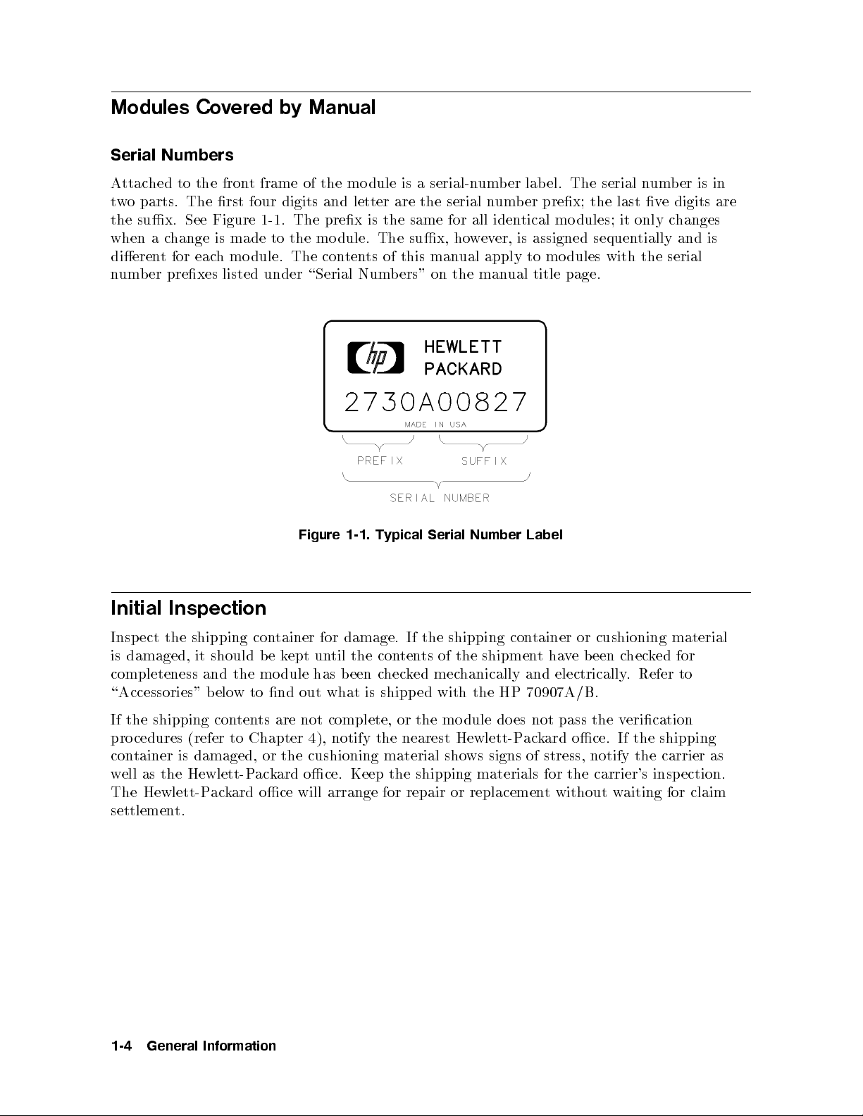
Modules Covered by Manual
Serial Numbers
Attached to the front frame of the mo dule is a serial-number lab el. The serial number is in
two parts. The rst four digits and letter are the serial number prex; the last ve digits are
the sux. See Figure 1-1. The prex is the same for all identical modules; it only changes
when a change is made to the mo dule. The sux, however, is assigned sequentially and is
dierent for each mo dule. The contents of this manual apply to modules with the serial
number prexes listed under \Serial Numbers" on the manual title page.
Label
con
tainer
or
ve
ha
t
and electrically
cushioning
chec
been
. Refer
ked
material
for
to
Initial
Insp
Inspection
the
ect
is damaged,
completeness
shipping con
the
b
mo
should
it
and
Figure
tainer for
ept
k
e
dule
un
has
1-1.
damage.
the
til
een
b
Typical
If
ten
con
k
hec
c
Serial
shipping
the
the
of
ts
mechanically
ed
Number
shipmen
\Accessories" below to nd out what is shipp ed with the HP 70907A/B.
If the shipping contents are not complete, or the mo dule do es not pass the verication
procedures (refer to Chapter 4), notify the nearest Hewlett-Packard oce. If the shipping
container is damaged, or the cushioning material shows signs of stress, notify the carrier as
ection.
aiting for
w
insp
claim
the
as
ell
w
Hewlett-P
The
settlemen
Hewlett-P
ack
t.
ard
k
ac
oce
ard
oce.
will
Keep the
arrange
for
shipping
repair
materials
replacemen
or
the
for
without
t
carrier's
1-4
General
Information

Accessories
The HP 70907A/B External Mixer Interface module may be ordered separately or as part
of a precongured HP 70000 Modular Measurement System. When ordered as part of a
precongured system, the mo dules come with cables that match the factory conguration.
When the mo dules are ordered separately, they are shipped with a group of accessories (refer
to Table 1-1) that allow the most common system congurations.
The accessories in this table are those available at the print date of this manual. For a list
of available system cables, refer to the Installation and Verication Manual for the system
master.
The information in the \L/R" column of the table refers to signal ow \out" to \in" as viewed
from the front panel. For example, if the signal source is to the left of the signal destination
when viewed from the front panel, a \L to R" cable is needed. Bends in the semirigid cables
make this distinction necessary.
Table 1-1. Accessories Shipped when the Module is Ordered Separately
y
tit
ed
Shipp
art
P
1 5021-5448
HP
Num
er
b
Semirigid
Flexible
cm
52
Flexible
Flexible
Flexible
coax
coax
(20
coax
coax
coax
LO
LO
in)
cable,
cable,
cable,
Accessory 1/8-Width
SMA (m)
to
(m)
SMA
cable,
cable,
SMB
SMB
SMB
SMA
(f
(f
(f
(m) to
to
)
to
)
to
)
SMA (m),
SMB
SMB (f
SMB
)
(f
)
)
(f
L/R Quan
Spans
R
1 L
to
n/a n/a 1 5061-9038
1 n/a 3 5061-9015
3 n/a 1 5061-9017
7 n/a 1 5061-9021
General
Information
1-5

Front- and Rear-Panel Features
Figures 1-2 and 1-3 show the HP 70907A/B front- and rear-panel features.
Status and Error LEDs
Both of the front-panel LEDs ash on, then o again, during the mo dule's self-test. Listed
below are the other reasons for each LED to light. For troubleshooting information, refer to
Chapter 5.
ACT The ACT (active) LED lights when the module has an active keyboard link to an
HP 70000 Mo dular Measurement System master and is being activated by that master.
If there is no display in the system, the ACT LED will not light even if the previous
requirements are met.
ERR The ERR (error) LED lights when an error condition exists.
Front-Panel Inputs and Outputs
dules.
PRESEL
MIXER
MIXER
or
TUNE/SP
OUT
BIAS
BIAS
AN
This
This
HP
the
This
mixers
)
(f
BNC
connector
11974
female
SMA
require
that
connector
vides
pro
Series
external mixer.
connector
bias.
is
a
only
dc
oltage
v
pro
presen
vides
in
t
whic
the
HP
hdriv
output
bias
70907B
es the
mo
preselector in
external
for
signal
LO
the
vides
from
pro
receiv
an
es
HP
the
70000
input
Mo
from
dular
OUTPUT
LO
INPUT
IF
Module
When
the
Latch
dule
mo
This
external
This
the
eing installed
is b
SMA
mixer.
SMA
external
in or
female
connector
female connector
mixer.
ed
remov
System mainframe, an 8 mm hex-ball driver is used to turn the mo dule latch.
IF
b
ort
p
required
the
Measuremen
the
y
of
t
1-6
General
Information

Figure 1-2. HP 70907A and HP 70907B Front-Panel Features
General
Information
1-7

Rear-Panel Inputs and Outputs
LO IN This SMA female connector is normally connected to the LO OUT on
the HP 70900 lo cal oscillator.
LO OUT This SMA female connector is normally terminated in 50.
TUNE SPAN This SMB male connector is normally connected to the TUNE SPAN on
the HP 70900 lo cal oscillator.
321.4 MHz OUT This SMB male connector supplies an auxiliary IF output. This
connector is not normally used.
300 MHz OUT This SMB male connector is for use with system congurations using
additional front-end modules.
300 MHz IN This SMB male connector is normally connected to the 300 MHz OUT
on the HP 70900 local oscillator.
21.4 MHz OUT This SMB male connector normally connects to the 21.4 MHz IN on the
IF section.
IN
MHz
21.4
Mainframe/Mo
terconnect
In
dule
SMB
This
additional
multiple-pin
This
supplies
er
w
o
p
(HP-MSIB)
male
fron
for
connector
mo
t-end
connector
Hewlett-P
and
mo
the
dules.
dule.
is
plugs
for
ac
use
k
in
ard
system congurations
with
mainframe
the
to
System
dular
Mo
and
terface
In
pro
using
vides
Bus
the
1-8
General
Information

Figure
1-3.
70907A/B
HP
Rear-P
anel
Features
General
Information
1-9

Electrostatic Discharge Information
Electrostatic discharge (ESD) can damage or destroy electronic comp onents. Therefore,
all work performed on assemblies consisting of electronic components should b e done at a
static-safe work station.
Figure 1-4 shows an example of a static-safe work station. Twotyp es of ESD protection are
shown: (a) conductive table mat and wrist strap combination, and (b) conductiveoormat
and heel strap combination. The twotyp es must be used together to ensure adequate ESD
protection. Refer to Table 1-2 for a list of static-safe accessories and their part numbers.
Figure 1-4. Static-Safe Work Station
Reducing ESD Damage
suggestions
are
w
Belo
servicing
testing
and
PC Board Assemblies and
that
instrumen
ts.
Electronic Components
help
y
ma
Handle these items at a static-safe w
Store or transp ort these
1-10
General
Information
items in static-shielding con
reduce
the
ork station.
amoun
ESD
tof
tainers.
damage
that
ccurs
o
during

Caution
Do not use erasers to clean the edge-connector contacts. Erasers generate
static electricity and degrade the electrical quality of the contacts byremoving
the thin gold plating.
Do not use paper of any kind to clean the edge-connector contacts. Paper
or lint particles left on the contact surface can cause intermittent electrical
connections.
Do not touch the edge-connector contacts or trace surfaces with bare hands.
Always handle board assemblies by the edges.
PC b oard assembly edge-connector contacts may be cleaned by using a lint-free cloth with a
solution of 80% electronics-grade isopropyl alcohol and 20% deionized water. This procedure
should b e performed at a static-safe work station.
Test Equipment
Before connecting any coaxial cable to an instrument connector for the rst time eachday,
momentarily
Personnel
an
of
pin
sure
Be
harge.
c
short the center and outer conductors of the cable together.
strap
should b
connector
y
all
that
grounded
e
and
instrumen
efore
b
ts
are
with
remo
prop
resistor-isolated
a
assem
y
an
ving
earth-grounded
erly
wrist
bly
from the
prev
to
touc
efore
b
instrument.
buildup
t
en
hing
of
the
static
cen
ter
General
Information
1-11

Static-Safe Accessories
Accessory Description
Table 1-2. Static-Safe Accessories
HP Part Number
Static-control mat and ground
Set includes: 9300-0797
wire
3M static-control mat, 0.6m21.2m
(2 ft24 ft)
ground wire, 4.6m (15 ft)
(The wrist strap and wrist-strap cord are
not
included. They must be ordered
separately.)
Wrist-strap cord 1.5m (5 ft) 9300-0980
adjustable
four
ost-t
not
is
12 mon
2
2
2.4m
in.
(23
1.8m
with
e
yp
included.)
ths
1.5m
1.2m
ft
(4
30
2
2
(4 ft
connector
2
ft
(4
2
ft
(3
ft)
8
2
in.)
ft)
6
5
4
(The
ft)
ft)
9300-1383
9300-1169
92175A
92175C
92175B
92175T
strap
Wrist
strap
heel
ESD
Hard-surface
Soft-surface
tistatic
static-con
carp
abletop
T
An
static-control
static-con
trol mat*
trol
et*
mat*
mat*
stainless steel
Black,
links and
7-mm p
wrist-strap cord
to
wn,
cm
6
black,
blac
1.2m
76
2
1.2m
k,
1.2m
0.9m
2
cm
2
Reusable
Large,
Small,
Bro
58
Small,
natural color 92176A
color
russet
92176C
e ordered
b
Phone
tact
can
Order
our
y
Service.
nearest
*These
accessories
HP DIRECT
538-8787. Con
DIRECT availability in other coun
1-12
General
Information
Large,
1.2m
2
2.4m
ft)
8
2
ft
(4
natural color 92176B
russet color 92176D
or
Oce
Sales
ard
k
DIRECT
Oce
ac
num
phone
more information
for
er
b
either
the
In
Hewlett-P
through
USA,
ard
k
ac
Hewlett-P
a
HP
the
Sales
tries.
through
(800)
is
out
ab
HP

Returning Instruments for Service
The original shipping containers and materials, or the equivalent, must be used when
repackaging the mainframe with modules, or modules alone. Packaging materials identical to
the original factory packaging (see Figure 1-5) can be purchased through any Hewlett-Packard
oce. However, if these shipping materials are not available, instruments can be repackaged
for shipment using the information b elow.
Caution
Instrument damage can result from using packaging materials other the
original shipping materials or equivalent. Never use styrene pellets as
packaging materials. They do not adequately cushion the instrumentor
prevent it from shifting in the carton. They cause instrumentdamageby
generating static electricity.
Use the following procedure to prepare the instrument for shipment:
1. Fill out a blue repair card (lo cated at the end of this manual) and attachittothe
instrument. Also send copies of any error messages and p erformance data recorded for the
Ho
t.
w
follo
ev
with the
er,
wing
instrumen
returned
a.
b.
c.
d.
e.
f.
g.
ac
P
2.
these
If
t.
instrumen
service required.
eof
yp
T
Description
k
ull
the
and
address.
um
del n
serial
an
of
instrumen
y
Name
Return
Mo
F
List
are not
blue
a
t:
the
of
er
um
n
returned
of
er
b
phone
b
n
accessories
tin
ailable,
v
a
repair
card
problem;
of
er
b
um
returned
of
returned
the original
instrumen
not
is
if
state
hnical
tec
instrumen
instrumen
with
shipping
can
ts
ailable,
v
a
problem
the
tact
con
t.
t.
instrumen
materials
repac
e
b
send
erson.
p
t.
aged
k
the
constan
is
(or
for
wing information
follo
termitten
in
or
t
alen
equiv
the
using
shipmen
t
t).
the
instructions.
if
ESD-caused
a.
W
rap
instrumen
the
ossibility
tistatic plastic
an
in
t
to reduce
the p
of
damage.
b. For instruments that weigh less than 54 kg (120 lb), use a double-walled, corrugated
cardboard carton of 159 kg (350 lb) test strength. The carton must be large enough and
strong enough to accommodate the instrument. Allow at least 3 to 4 inches on all sides
of the instrument for packing material.
Surround
c.
instrumen
the equipmen
t
the b est alternativ
California
pink (an
times
90001). Air Cap is a plastic sheet lled with 1-1/4 inc
tistatic) Air Cap to reduce static electricity
in this material should both protect the instrumen
and
to
3
with
t
from mo
it
t
en
prev
e is S.D.-240 Air Cap
inc
4
ving
material to
king
pac
of
hes
king
pac
carton.
the
in
TM
from Sealed Air Corporation (Commerce,
If
protect
foam
h air bubbles. Use the
rapping the
.W
t and prev
instrumentseveral
entitfrommo
the
not
is
the carton.
3. Seal the carton with strong nylon adhesive tape.
4.
5.
Mark
Retain
the
copies
carton
of
\FRA
shipping
all
GILE,
HANDLE
ers.
pap
WITH
CARE."
General
Information
vailable,
a
ving in
1-13

Item HP Part Number Qty Description
1 9211-5118 1 Carton-Outer
2 9211-5119 1 Carton-Inner
3 5180-2369 1 Carton-Slider
4 4208-0493 2 Foam Insert
5 5180-2370 2 Foam Pad
&sigspace;
Figure 1-5. Packaging Materials for Modules
1-14
General
Information

Sales and Service Offices
Hewlett-Packard sales and service oces provide complete support for Hewlett-Packard
products. To obtain servicing information, or to order replacementparts,contact the nearest
Hewlett-Packard Sales and Service Oce listed in Table 1-3.
In any correspondence, be sure to include the p ertinent information ab out model numbers,
serial numbers, or assembly part numbers.
General
Information
1-15

Table 1-3. Hewlett-Packard Sales and Service Offices
IN THE UNITED STATES IN AUSTRALIA IN JAPAN
California
Hewlett-Packard Australia Ltd. Yokogawa-Hewlett-Packard Ltd.
Hewlett-Packard Co. 31-41 Joseph Street 29-21 Takaido-Higashi, 3 Chome
1421 South Manhattan Ave. Blackburn, Victoria 3130 Suginami-ku Tokyo168
P.O. Box 4230 895-2895 (03) 331-6111
Fullerton, CA 92631
(714) 999-6700
Hewlett-Packard Co. 17500 South Service Road
IN CANADA
Hewlett-Packard (Canada) Ltd.
IN PEOPLE'S REPUBLIC
OF CHINA
301 E. Evelyn Trans-Canada Highway China Hewlett-Packard, Ltd.
Mountain View, CA 94039 Kirkland, Quebec H9J 2X8 P.O. Box 9610, Beijing
(415) 694-2000 (514) 697-4232 4th Flo or, 2nd WatchFactory
Main Bldg.
Colorado IN FRANCE
Shuang YuShu, Bei San Huan Rd.
Hewlett-Packard Co. Hewlett-Packard France Beijing, PRC
24 Inverness Place, East F-91947 Les Ulis Cedex 256-6888
Englewood, CO 80112 Orsay
907-78-25
649-5000
(303)
Georgia
Hewlett-P
South
2000
x
Bo
.O.
P
ta,
tlan
A
955-1500
(404)
Illinois
Hewlett-P
ollview
T
5201
Rolling
(312)
New
Meado
255-9800
Jersey
ard
k
ac
ark
P
105005
30339
GA
ard
k
ac
Driv
ws,
Co.
Place
Co.
e
60008 Hewlett-P
IL
(6)
GERMAN
IN
REPUBLIC
Strasse
560
h
rankfurt
F
50-04-1
GREAT
ac
Hewlett-P
ertriebszen
V
Berner
ostfac
P
D-6000
(0611)
IN
ack
King Street
Winnersh,
Berkshire
R
IN
FEDERAL
Hewlett-P
Pte.
ard
k
trale
117
140
BRIT
ard
bH
Gm
rankfurt
F
56
AIN
Ltd.
1150 Dep
Singap
273
elex
T
ax
F
IN
Hewlett-P
Lane 8th
okingham Building
W
G11 5AR
337 F
SINGAPORE
ard
k
ac
Ltd.
ot Road
0410
ore
7388
HPSGSO
2788990
(65)
AN
AIW
T
ard
k
ac
Hewlett-Pac
Floor,
uHsing
North
Singap
RS34209
an
aiw
T
k
Road
ore
ard
Hewlett-Packard Co. 0734 784774 Taip ei
120 W. Century Road (02) 712-0404
Paramus, NJ 07653
(201) 265-5000
exas
T
Co. CH-8967
ard
k
Hewlett-P
930 E. Campbell
ac
Rd. (0041) 57 31 21 11
IN OTHER EUROPEAN
COUNTRIES
eiz)
w
h
(Sc
ard
k
Hewlett-P
Allmend
ac
2
Widen
(Zuric
h)
OTHER
ALL
IN
AG
ard
Deer
k
Creek
Hewlett-Pac
3495
Palo Alto, California 94304
TIONS
LOCA
ter-Americas
In
Rd.
Richardson, TX 75081
(214) 231-6101
1-16
General
Information

Installation
This chapter contains information needed to install the HP 70907A/B External Mixer
Interface module (EMIM) into an existing HP 71210C system and then check basic module
operation.
For more detailed information about system conguration and addressing, refer to the
Installation and Verication Manual for the system master (for example, HP 70900B Local
Oscillator).
Installing the EMIM requires the following steps:
1. Addressing the module.
mainframe.
the
in
dule
mo
erly
dule's
an
in
equipmen
the
rear-panel cables.
installed,
rear-panel
eration"
Op
dule
addressing and
of
71210C
HP
t:
the
EMIM
obtains
mainframe/mo
this
in
cable
system.
The
oth
b
interconnect.
dule
hapter
c
to
connections
system
sho
o
p
mak
in
wn
w
e
this
er
and in
After the
sure
hapter
c
Figures
in
terface-bus con
EMIM
has
it
that
for
are
and
2-1
b
is
een
an
2-4
through
trol
installed,
erly
prop
70907A/B
HP
tains
con
use
installed.
the
Installing
2.
Connecting the
3.
When
the
\Chec
The
prop
mo
king Mo
examples
installed
wing
follo
2
70907B
HP
HP 71210C
HP
HP
HP
HP
External
High Sensitivit
70001A
70004A
70310A
Mainframe
Displa
Precision F
70900B Lo
HP 70902A IF Section
HP 70903A IF Section
HP 70908A RF Section
Caution
T
APC
Do not exceed 10 inc
o
cal
prev
Mixer
y
Oscillator
connector
t
en
and
3.5
dule
In
y
terface
Micro
mo
ectrum
Sp
e
v
a
w
requency Reference
damage
SMA connectors
h-pounds.
and
m
ensure
ust
Analyzer,
prop
torqued
e
b
consists
h
whic
er electrical
inc
10
to
7
the
of
connection,
ounds.
h-p
follo
all
wing:
Installation
2-1

Addressing the Module
The EMIM needs an appropriate Hewlett-Packard Mo dular System Interface Bus (HP-MSIB)
address to b e able to communicate with the master of the HP 70000 Mo dular Measurement
System. The EMIM's address is set using its ROW and COLUMN address switches.
Note
The EMIM can be used in most system congurations without changing the
factory-preset address.
Determining the HP-MSIB Address
The EMIM has a factory-preset HP-MSIB address of 5, 18 (row 5, column 18). Figure 2-1
shows the address map for an EMIM in an HP 71210C system. The addresses in this gure
are the factory-preset addresses for the modules. When a system containing an EMIM is
turned on, the system master selects the front end (EMIM or RF section) that is lo cated
lowest in the address map. As seen in the gure below, the HP 70907B is lower in the address
map than the HP 70908A. Therefore, the EMIM will be selected when the system is turned
on.
Figure
2-1.
Address
Map for
an
EMIM
71210C
HP
an
in
System
If the EMIM is going to be used in an HP 70000 Modular Spectrum Analyzer System where
the mo dules all ha
ve their factory-preset addresses, the EMIM
have its factory-preset address c
modules in the system ha
vebeen c
hanged. Ho
hanged,
wever, if the factory-preset addresses of the
or if the EMIM is being used in another t
probably will not need to
ype of
HP 70000 Mo dular Measurement System, the EMIM's factory-preset address may need to be
changed. For more information about HP-MSIB addressing rules, refer to the Installation and
Oscillator).
cal
erication
V
Installation
2-2
Man
ual
for
the
system
master
(for
example,
HP
70900B
Lo

Setting the HP-MSIB Address Switches
The EMIM's address switches are lo cated on the right side of the mo dule. Table 2-1 gives the
decimal value for each address switch when the switch is set to binary 1 (on).
Table 2-1. Decimal Equivalents of Row and Column Address Switches
Address Switch Decimal Value
Row
3* 4
2 2
1* 1
Column
5* 16
4 8
3 4
2* 2
1 1
factory-preset
are
hes
binary
5,
w
switc
(on),
1
address
column
resulting
of
18).
an
in
18
5,
*These
to
HP-MSIB
(ro
Use
1.
2.
the
the
Set
example,
or
F
Figure
the
Set
b
um
n
wn
sho
pro
er.
in
cedure
three
.
2-2
e
v
F
Figure
or
w
elo
b
switc
W
O
R
ro
the
if
COLUMN
example,
2-2.
hes:
v
binary
ber
switc
alue
the
v
is 18,
of
switc
alue
mo
the
hes
the
of
change
dule's HP-MSIB
binary
to
mo
the switc
to
w
switc
if
n
c
hes
um
the
hange
to
er is
b
hes
column
the
the
to
address
binary
hange
c
5,
the
n
um
Figure 2-2. HP 70907A/B Address Switches
dule's
sho
as
101
HP-MSIB
binary
to
hes
ro
w
wn
um
n
in
column
10010
er.
b
as
Installation
2-3

Installing the Module in the Mainframe
The EMIM needs to be installed in an HP 70000 series mainframe before it will operate.
Follow the pro cedure b elow to install the module into the mainframe. See Figure 2-3 for
identication of the module and mainframe parts called out in the procedure.
1. Turn the mainframe LINE switcho.
2. Open the mainframe front-panel door.
3. Slide the module into the mainframe.
4. Press against the module front panel while tightening the mo dule latch with an 8 mm
hex-ball driver.
5. Close the mainframe front-panel do or.
2-4
Figure 2-3. Module Installation in Mainframe
Installation

Connecting the Rear-Panel Cables
This section contains the instructions for connecting the EMIM when it is used in an existing
HP 71210C system. For HP 71210C system conguration information, refer to the Installation
and Verication Manual for the system's master.
Figure 2-4 illustrates the rear-panel cable connections for the HP 71210C system with an
EMIM added. Make the following changes and additions to the HP 71210C system cabling
when an EMIM is added:
Disconnect the cable b etween HP 70903A 21.4 MHz IN and HP 70908A 21.4 MHz OUT.
Disconnect the RF-section end of the cable connected b etween HP 70900B TUNE SPAN
and HP 70908A TUNE SPAN. Connect an SMB tee (1250-1391) to HP 70908A TUNE
SPAN, then connect the cable from HP 70900B TUNE SPAN to the tee.
Connect the following ports with the cables listed:
HP 70907B LO IN to HP 70908A 1ST LO OUT. (5021-5493)
HP 70907B TUNE SPAN to the tee on HP 70908A TUNE SPAN. (5061-9017)
HP 70907B 300 MHz IN to HP 70900B 300 MHz OUT 2. (5061-9021)
(5061-9021)
IN.
MHz
21.4
21.4
MHz
OUT.
(5061-9017)
70907B 21.4
HP
70907B
HP
21.4
MHz OUT
to
IN
MHz
to HP
70908A
HP
70903A
Installation
2-5

2-6
Figure 2-4. Rear-Panel Cabling for an EMIM in an HP 71210C System
Installation

Checking Module Operation
The op eration of the HP 70907A/B in an HP 70000 Mo dular Sp ectrum Analyzer system is
checked by examining the front-panel LEDs and bychecking for error messages after the
module's power-on self-test has run. Recheck installation if there seems to be a problem with
module operation, but neither the front-panel LEDs nor error messages indicate a problem.
Examining the Front-Panel LEDs
The p ower-on self-test runs automatically when power is rst applied to the module. The
front-panel LEDs ash on and then o during the
self-test. Immediately after the self-test has run, the ACT LED should beonand the ERR
LED should beo. Refer to Chapter 5, \Troubleshooting," if the LEDs' status is dierent
than that listed above.
Checking for Error Messages
Perform this procedure to displayany error messages present for the system.
NN
NN
NN
N
N
N
N
N
N
N
N
N
N
N
N
N
N
N
N
N
NN
NN
NN
NN
N
N
N
N
N
N
N
N
N
e
v
are
N
REPORT
the
for
70907A
mo
the
has
ERRORS
system
70907B
or
dule's
een
b
.
will
HP-MSIB
hanged.
c
as
b
visible
e
part
on
the
of
address
the displa
co
error
18),
(5,
y screen.
The
de.
and
will
last
b
Note
w
t
dieren
e
error
y
an
ers
b
um
n
o
the
if
t
1.
2.
Press
The
4
error
messages
of the
factory-preset
DISPLA
messages
that
error
, then
5
Y
ha
de
co
address
3.
If
no
an
error
y
error
messages
messages
are
displa
are
present,
y
the
ed,
HP
to Chapter
refer
70907A/B
is
5
erating
op
troublesho
for
prop
erly
oting
.
information.
If
Installation
2-7


3
Specifications
This chapter contains mo dule characteristics for the HP 70907A and HP 70907B External
Mixer Interface modules. Refer to the Installation and Verication Manual for the system
master (for example, HP 70900B) for full system specications and system specications that
are mo died when an HP 70907A/B is added to a system.
This chapter contains both sp ecications and characteristics. Characteristics are in
are identied with the word
characteristic
. The terms \specications" and \characteristics"
are dened below:
Specications
describe warranted performance over the temperature range of 0Cto
+55C (unless otherwise noted) after 1 hour of continuous operation.
and
specication
indicates
information.
Characteristics
alues
Nominal
v
after
ecications
Sp
apply
self-calibration routines
Unless
range
otherwise
is
qualied
vide
p
useful,
Typical
erformance
p
pro
indicate
impro
y
b
erformance
the exp
noted,
with error-correction
ved
output-p
an
,
most
h
whic
nonwarr
but
ected, but
system
hav
corrected
er
w
o
where
units
nonwarr
e run.
setting
listed,
will
ante
,
d
temperatures
giv
limits
are
routines.
to
refer
warr
not
is
meet.
functional
alue
v
,
d
ante
e stabilized
hav
when
en
All
setting.
that
d
ante
performance
and
the
of
a
ecications
sp
but
,
denoted
italics
that
parameter.
and
are
Specifications
3-1

HP 70907A Module Specifications and Characteristics
Front-Panel Inputs and Outputs
For HP 70907A front-panel input and output specications and characteristics, refer to the
Installation and Verication manual for the system master (for example, HP 70900B Local
Oscillator).
Rear-Panel Inputs and Outputs
LO IN
Frequency (characteristic) . . . . . . . . . . . . . . . . ................. ... 3.0 to 6.6 GHz
Input Power (characteristic) ......... ............. ....00.5 dBm to +19.0 dBm
Impedance ..................................................50
LO OUT
.
.
.
.
.
.
..
..
..
.
.
.
.
.
.
.
.
.
.
.
.
.
.
.
.
equency
Fr
Output
VSWR
edance
Imp
Range
Power
(char
(char
acteristic)
(char
acteristic)
..
..
.
.
.
.
acteristic)
.
.
.
.
.
.
.
.
.
.
+2.6
.
.
.
.
.
.
.
..
..
..
..
.
.
.
.
.
.
.
.
.
.
.
.
.
.
..
.
.
.
.
.
.
.
.
.
.
.
.
.
.
.
.
.
.
.
.
.
..
..
.
.
.
.
.
.
.
.
.
.
.
.
.
.
.
.
.
.
.
.
.
.
.
..
..
.
.
.
.
.
.
.
.
.
.
.
.
.
.
.
.
..
3.0
50
.
.
(nominal)
6.6
to
13.9
to
.
.
.
.
.
(nominal)
.
GHz
dBm
2.3
AN
TUNE
321.4
The
300 MHz OUT
300 MHz IN
SP
to 9.9
4.5
.
.
.
.
.
.
.
.
.
.
.
.
.
.
.
.
.
.
.
.
.
.
..
.
.
.
.
.
.
.
.
.
.
.
.
.
.
.
acteristic)
edance
MHz
output
quency
e
quency
e
edance
(char
acteristic)
(char
..
.
.
.
.
OUT
21.4
acks
tr
(char
ange
R
(characteristic)
Power
at 300
(char
300 MHz (char
.............
MHz
.
.
.
.
.
.
oltage
V
Sensitivity
Imp
r
F
Frequency Response (characteristic) .. ............. .......+1.0,02.0 dB typical
Return Loss (characteristic) . . . . . . . . . . . . . . ................. ............9 dB
Impedance ..................................................50
r
F
Output
VSWR at
Impedance
Frequency (characteristic) . . . . . . . . . . . . . . . . ................. 300 MHz610 kHz
Input Power (characteristic) ......... ............. ............02to +2dBm
VSWR
Imp
.
.
.
.
.
.
.
.
.
.
.
.
.
.
.
.
OUT
MHz
acteristic)
.
.
.
.
.
acteristic)
acteristic) . . . . . . . .
acteristic)
(char
.
.
.
.
.
.
.
.........................
.
.
.
.
.
.
.
.
.
.
with
.
.
.
.
.
.
..
V/GHz
1.5
.
..
.
.
.
.
.
.
.
.
.
.
.
.
.
.
.
.
.
.
.
.
.
.
.
..
.
.
.
.
(nominal)
k
10
>
.
.
.
.
.
.
.
.
.
.
.
.
.
.
.
..
.
.
.
.
.
.
.
.
.
dB.
2
6
20
0
of
oset
an
(nominal)
.
.
.
.
dBm
0
(nominal)
.
.
.
.
(nominal)
25 MHz
6
300
6
.
.
.
321.4
..
.
.
.
.
.
.
.
.
.
.
.
.
.
.
.
.
.
..
..
..
..
.
..
.
.
.
.
.
.
.
.
.
.
..
.
.
.
.
.
.
.
.
.
.
.
..
.
.
.
..
.
.
.
.
.
.
.
.
.
.
.
..
.
.
.
.
.
.
.
.
.
.
..
.
.
.
.............
.
.
.
.
.
.
.
.
.
.
.
.
.
.
.
.
.
.
.
.
.
.
.
.
.
.
.
.
.
.
.
.
.
............. ..
............50
.
.
.
.
.
.
.
..
.
.
.
.
50
.
.
.
.
.
.
..
.
.
.
.
.
V
MHz
dB
1
1.5
1.5
Specifications
3-2

21.4 MHz OUT
Center Frequency (characteristic) ..... ............. ............. .. 21.4 MHz
VSWR (characteristic)
at 21.4 MHz ........ ............. ............. ............. ......1.5
at 21.4 MHz65.0 MHz ................. ............. ............. .1.9
Impedance ..................................................50
(nominal)
21.4 MHz IN
Frequency (characteristic) ............ ............. ........21.4 MHz65 MHz
Maximum Input Power (characteristic) ......... ............. ......03.5 dBm
VSWR (characteristic) ...... ............. ............. ............. .1.5
Impedance ..................................................50
(nominal)
General Specifications and Characteristics
Temperature
Operation . . . . . . . . . . ....................................... 0C to +55C
10
0
.
.
.
.
..
..
..
.
.
.
.
.
.
.
.
.
.
.
.
.
.
.
.
.
.
.
..
..
..
.
.
.
.
.
.
.
.
.
.
.
.
.
Storage
70907A
HP
70907A Dimensions
HP
.
Weight
acteristic)
(char
(characteristic)
+75
to
C
kg (6.2
.2.8
.
.
.
.
.
.
.
.
.
.
.
.
.
.
.
.
.
..
..
..
..
.
.
.
1/8-width mo
..
.
.
.
.
.
.
.
.
.
.
.
.
.
.
.
.
.
..
..
C
lb)
dule
Specifications
3-3

HP 70907B Module Specifications and Characteristics
Front-Panel Inputs and Outputs
For HP 70907B front-panel input and output specications and characteristics, refer to the
Installation and Verication manual for the system master (for example, HP 70900B Local
Oscillator).
Rear-Panel Inputs and Outputs
LO IN
Frequency (characteristic) . . . . . . . . . . . . . . . . ................. ... 3.0 to 6.6 GHz
Input Power (characteristic) ......... ............. ....00.5 dBm to +19.0 dBm
Impedance ..................................................50
LO OUT
.
.
.
.
.
.
..
..
..
.
.
.
.
.
.
.
.
.
.
.
.
.
.
.
.
equency
Fr
Output
VSWR
edance
Imp
Range
Power
(char
(char
acteristic)
(char
acteristic)
..
..
.
.
.
.
acteristic)
.
.
.
.
.
.
.
.
.
.
+2.6
.
.
.
.
.
.
.
..
..
..
..
.
.
.
.
.
.
.
.
.
.
.
.
.
.
..
.
.
.
.
.
.
.
.
.
.
.
.
.
.
.
.
.
.
.
.
.
..
..
.
.
.
.
.
.
.
.
.
.
.
.
.
.
.
.
.
.
.
.
.
.
.
..
..
.
.
.
.
.
.
.
.
.
.
.
.
.
.
.
.
..
3.0
50
.
.
.
(nominal)
6.6
to
13.9
to
.
.
.
.
.
(nominal)
GHz
dBm
2.3
AN
TUNE
321.4
The
300 MHz OUT
300 MHz IN
SP
ating)
(o
V
9.9
to
4.5
.
.
.
.
.
.
.
.
.
.
.
.
.
.
..
.
.
.
.
.
.
.
.
.
.
.
.
.
.
.
acteristic)
edance
MHz
output
quency
e
quency
e
edance
(char
acteristic)
(char
..
.
.
.
.
OUT
21.4
acks
tr
(char
ange
R
(characteristic)
Power
at 300
(char
300 MHz (char
.............
MHz
.
.
.
.
.
.
oltage
V
Sensitivity
Imp
r
F
Frequency Response (characteristic) .. ............. .......+1.0,02.0 dB typical
Return Loss (characteristic) . . . . . . . . . . . . . . ................. ............9 dB
Impedance ..................................................50
r
F
Output
VSWR at
Impedance
Frequency (characteristic) . . . . . . . . . . . . . . . . ................. 300 MHz610 kHz
Input Power (characteristic) ......... ............. ............02to +2dBm
VSWR
Imp
.
.
.
.
.
.
.
.
.
.
.
.
.
.
.
.
OUT
MHz
acteristic)
.
.
.
.
.
acteristic)
acteristic) . . . . . . . .
acteristic)
(char
.
.
.
.
.
.
.
.........................
.
.
.
.
.
.
.
.
.
.
with
.
.
.
.
.
.
..
V/GHz
1.5
.
..
.
.
.
.
.
.
.
.
.
.
.
.
.
.
.
.
.
.
.
.
.
.
.
..
.
.
.
.
(nominal)
k
100
>
.
.
.
.
.
.
.
.
.
.
.
.
.
.
..
.
.
.
.
.
.
.
.
.
dB.
2
6
20
0
of
oset
an
(nominal)
.
.
.
.
dBm
0
(nominal)
.
.
.
.
(nominal)
25 MHz
6
300
6
.
.
.
321.4
..
.
.
.
.
.
.
.
.
.
.
.
.
.
.
.
.
.
..
..
..
..
.
..
.
.
.
.
.
.
.
.
.
.
..
.
.
.
.
.
.
.
.
.
.
.
..
.
.
.
..
.
.
.
.
.
.
.
.
.
.
.
..
.
.
.
.
.
.
.
.
.
.
..
.
.
.
.............
.
.
.
.
.
.
.
.
.
.
.
.
.
.
.
.
.
.
.
.
.
.
.
.
.
.
.
.
.
.
.
.
.
............. ..
............50
.
.
.
.
.
.
.
..
.
.
.
.
50
.
.
.
.
.
.
..
.
.
.
.
.
MHz
dB
1
1.5
1.5
Specifications
3-4

21.4 MHz OUT
Center Frequency (characteristic) ..... ............. ............. .. 21.4 MHz
VSWR (characteristic)
at 21.4 MHz ........ ............. ............. ............. ......1.5
at 21.4 MHz65.0 MHz ................. ............. ............. .1.9
Impedance ..................................................50
(nominal)
21.4 MHz IN
Frequency (characteristic) ............ ............. ........21.4 MHz65 MHz
Maximum Input Power (characteristic) ......... ............. ......03.5 dBm
VSWR (characteristic) ...... ............. ............. ............. .1.5
Impedance ..................................................50
(nominal)
General Specifications and Characteristics
Temperature
Operation . . . . . . . . . . ....................................... 0C to +55C
10
0
.
.
.
.
..
..
..
.
.
.
.
.
.
.
.
.
.
.
.
.
.
.
.
.
.
.
..
..
..
.
.
.
.
.
.
.
.
.
.
.
.
.
Storage
70907B
HP
70907B Dimensions
HP
.
Weight
acteristic)
(char
(characteristic)
+75
to
C
kg (6.2
.2.8
.
.
.
.
.
.
.
.
.
.
.
.
.
.
.
.
.
..
..
..
..
.
.
.
1/8-width mo
..
.
.
.
.
.
.
.
.
.
.
.
.
.
.
.
.
.
..
..
C
lb)
dule
Specifications
3-5


4
Verification
The HP 70907A/B External Mixer Interface module (EMIM) does not haveany module
specications. Operation of the EMIM in the system can b e veried by using the system
master's op eration verication software.
System-level performance sp ecications for the EMIMs, including system specications that
are mo died when an EMIM is added to a system, are in the Installation and Verication
Manual for the system master (for example, HP 70900B Local Oscillator). System-level
testing of systems controlled by an HP 70900 lo cal oscillator can be accomplished in twoways:
Run the system op eration-verication tests, using revision C.00.00 or greater. (For system
operation verication, refer to the Installation and Verication Manual for the system's
master.)
11990A
HP
Run
soft
w
the
are
HP
and
11990A
cumen
do
system
tation
tests,
are
using
ailable
v
a
revision
through
B.04.00
Hewlett-P
greater.
or
ack
The
ard Sales
Oces.
System-lev
the
using
system
that
for
system
that
for
testing
el
system
systems
of
eration-v
op
master. HP
master.
trolled
con
erication
11990
Series
b
tests
system
y
giv
other
en
system
the Installation
in
can
tests
masters
b
also
e
can
and
used,
accomplished b
e
b
erication
V
are
they
if
ailable
v
a
Man
y
ual
erification
V
4-1


5
Troubleshooting
The information in this chapter is designed to help determine whether an error is being
caused by the HP 70907A/B External Mixer Interface mo dule (EMIM). This chapter contains
information ab out EMIM front-panel LEDs, and a listing of the error codes for the EMIM.
For more detailed HP 70907A/B troubleshooting information, refer to the
External Mixer Interface Service Manual
.
HP 70907A/B
If the error is not caused by the EMIM, refer to the Installation and Verication Manual for
the system master (for example, HP 70900B) for more troubleshooting information.
Front-P
The
The
Mo
displa
met.
The
Error
anel
70907A/B
HP
CT
A
dular Measuremen
in
y
The
ERR
Messages
LEDs
(activ
system,
the
CT
A
(error)
External
LED
e)
LED
LED
lights
System
t
the
eing
b
ligh
Mixer
when the
master
CT
A
do
lit
ts when
In
LED
es
terface
mo
and
will
indicate
not
there
not
is
mo
dule
is
an
dule
has
eing
b
ligh
an error.
error
t
has
an
activ
en
ev
t
condition.
front-panel
o
w
e
activ
ated
the
if
oard
eyb
k
that
y
b
previous
LEDs.
to
link
master.
requiremen
If
an
there
HP
is
ts are
70000
The error co des generated by the HP 70907A/B External Mixer Interface mo dule are listed
belowinnumerical order. For a complete list of all system error messages, refer to the
Installation and Verication Manual for the system master.
ers
es
yp
Error
T
Usage/Operating . . . . . .
Hardware W
arning .
Hardware Brok
en ..............
.........................
..........
.........................
.................. 6000 to 6999
.........................
Error Num
. . . . . 2000 to 2999
. . . . . . 7000 to 7999
b
no
Troubleshooting
5-1

Usage/Operating Errors
These errors o ccur when the instrument is used incorrectly.
2000 Rom check error
| A test of the module ROM has failed. The most probable cause is
faulty HP 70907A/B hardware.
2001 Illegal Cmd
| This error usually occurs in response to a user-generated system
protocol error: the mo dule has encountered a command that it does not recognize. This
can b e caused by the system master's sending such a command, however; if the error is
repeated when the mo dule is moved to another mainframe, the most probable cause is
faulty HP 70907A/B hardware.
2002 Illegal parameter
2006 Param out of range
2009 Protocol error
2026 Check mixer bias
| Refer to
|Referto
| Refer to
2001 Illegal Cmd
2001 Illegal Cmd
2001 Illegal Cmd
.
.
.
| This error o ccurs in resp onse to an improp er load imp edance
on the front-panel mixer-bias p ort. If the imp edances are correctly matched, the most
can
that
accuracy
t
Hardw
These
hardw
the
probable
when the
only
W
are
co
error
are
cause
arning
rep
des
b
y
ma
fault
is
mixer-bias
Errors
the
ort
en.
brok
e
HP
y
status
These
70907A/B
supply
of
error
is
the
activ
HP
des
co
hardw
are.
ated.)
70907A/B
indicate that
(This
hardw
message
error
indicate
or
are
measuremen
impaired.
generated
e
b
some
ma
of
e
b
y
dule's
6000
Hardw
EAROM
P
A4
ccurs
o
70907A/B
HP
are
unprotected
Supply/Con
er
w
o
the
when
en Errors
Brok
switc
hardw
|
trol
h
are.
write-protect
The
oard
b
the
in
is
assem
protect
switc
is
bly
position,
h
set
the
on
the
to
the most
HP
write
70907A/B
osition. If
p
probable
mo
cause
this
is
error
fault
y
The following error codes are generated in resp onse to hardware or rmware failures within
the mo dules.
7001 LO unleveled
| The output power is to o low from the A5 Leveling Amplier
assembly's primary LO output p ort. The most probable cause is faulty HP 70907A/B
hardware.
error
MHz
300
7004
300 MHz input. V
0
1 dBm and +1 dBm. If the
HP 70907A/B hardw
7005 321.4 MHz error
error o
This
|
erify that the 300 MHz input signal has a po
are.
| This error occurs
ccurs
input po
etween
wer lev
el b
wer is correct, the most probable cause is faulty
when 321.4 MHz IF po
wer lev
el is to o lo
wonthe
rear-panel
the
at
w
olo
to
is
el
lev
er
w
o
p
the
when
A3 Last Converter b oard assembly. This error is usually accompanied by error number
7006 21.4 MHz error
MHz error
21.4
7006
Last
A3
321.4
7005
Con
erter
v
MHz
. The most probable cause is faulty HP 70907A/B hardware.
is
el
lev
er
w
o
p
IF
MHz
21.4
when
ccurs
o
error
This
|
oard
b
error
.
assem
The
bly
most
This
.
probable
error
cause
usually
is
is
accompanied
y
fault
70907A/B
HP
b
w
lo
o
to
error
y
hardware.
n
on
the
um
ber
Troubleshooting
5-2

Index
A
accessories
cables, 1-5
electrostatic discharge, 1-12
ACT LED, 1-6
address map, 2-2
address switches
decimal value, 2-3
location, 2-3
setting, 2-3
C
cables,
1-5
rear-panel
connections,
E
(ESD),
harge
des,
ts,
disc
1-6
5-1
1-6
{2
,
5-1
electrostatic
LED,
ERR
co
error
ligh
error
H
70907A/B
HP
mainframe,
installing
rear-panel
in
cable
connections,
HP-MSIB
address, 2-2
connector, 1-8
2-5
2-4
{6
1-10
2-5
{12
{6
I
input and output connectors, 1-8
L
LEDs, 1-6
LO rmware compatibility
HP 70907A, 1-2
HP 70907B, 1-2
M
conguration, 2-1
dule
mo
errors, 5-1
dule
mo
mo
dule-op
eration
hecks,
c
2-7
P
1-13
aging,
k
pac
PC
b
oard
connector
cleaning,
1-10
R
rear-panel cable
connections,
2-5
S
sales
select
correct
and
service
oces,
input
HP-MSIB address,
1-15
2-2
serial-number label, 1-4
shipping materials, 1-13
static-safe work station, 1-10
status and error LEDs, 1-6,5-1
sweeptime, 1-2
system-lev
testing,
el
4-1
{6
Index-1

 Loading...