


Service Guide
HP 70902A
IF Section
ABCDE
HP Part No. 70902-90079
Printed in USA December 1992

Notice.
The information contained in this document is sub ject to change without notice.
Hewlett-Packard makes no warrantyofany kind with regard to this material, including
but not limited to, the implied warranties of merchantability and tness for a particular
purpose. Hewlett-Packard shall not be liable for errors contained herein or for incidental or
consequential damages in connection with the furnishing, p erformance, or use of this material.
c
Copyright Hewlett-Packard Company 1988, 1992
All Rights Reserved. Reproduction, adaptation, or translation without prior written
permission is prohibited, except as allow
1212 Valley House Drive, Rohnert Park, CA 94928-4999, USA
ed under the copyrightlaws.

Certification
Hewlett-Packard Company certies that this product met its published specications at the
time of shipment from the factory. Hewlett-Packard further certies that its calibration
measurements are traceable to the United States National Institute of Standards and
Technology, to the extent allowed by the Institute's calibration facility, and to the calibration
facilities of other International Standards Organization members.
Warranty
This Hewlett-Packard instrument product is warranted against defects in material and
workmanship for a p eriod of one year from date of shipment. During the warranty period,
Hewlett-Packard Company will, at its option, either repair or replace products which proveto
be defective.
For warranty service or repair, this product must be returned to a service facilit y designated
by Hewlett-Packard. Buyer shall prepay shipping charges to Hewlett-Packard and
Hewlett-Packard shall pay shipping charges to return the product to Buyer. However, Buyer
shall pay all shipping charges, duties, and taxes for pro ducts returned to Hewlett-P
ackard
from another country.
Hewlett-Packard warrants that its software and rmware designated by Hewlett-Packard for
use with an instrument will execute its programming instructions when properly installed on
that instrument. Hewlett-Packard does not warrant that the operation of the instrument, or
software, or rmware will be uninterrupted or error-free.
Limitation of Warranty
The foregoing warranty shall not apply to defects resulting from improp er or inadequate
maintenance by Buyer, Buyer-supplied software or interfacing, unauthorized modication or
misuse, operation outside of the environmental specications for the product, or improper
site preparation or maintenance.
NO OTHER WARRANTY IS EXPRESSED OR IMPLIED. HEWLETT-PACKARD
SPECIFICALLY DISCLAIMS THE IMPLIED WARRANTIES OF MERCHANTABILITY
AND FITNESS FOR A PARTICULAR PURPOSE.
Exclusive Remedies
THE REMEDIES PROVIDED HEREIN ARE BUYER'S SOLE AND EXCLUSIVE
REMEDIES. HEWLETT-PACKARD SHALL NOT BE LIABLE FOR ANY DIRECT,
INDIRECT, SPECIAL, INCIDENTAL, OR CONSEQUENTIAL DAMAGES, WHETHER
BASED ON CONTRACT, TORT, OR ANY OTHER LEGAL THEORY.
Assistance
Product maintenance agreements and other customer assistance agreements are available for
Hewlett-Packardproducts.
For any assistance, contact your nearest Hewlett-Packard Sales and Service Oce.
iii
Safety Notes
The following safety notes are used throughout this manual. Familiarize yourself with eachof
the notes and its meaning before operating this instrument.
Caution
Warning
Instruction
Manual
L
Caution
correctly performed or adhered to, could result in damage to or destruction
of the instrument. Do not pro ceed beyond a
conditions are fully understo od and met.
Warning
correctly performed or adhered to, could result in injury or loss of life. Do
not proceed beyond a
understood and met.
The
necessary for the user to refer to the instructions in the man
denotes a hazard. It calls attention to a procedure that, if not
caution
denotes a hazard. It calls attention to a procedure which, if not
instruction manual
warning
symbol. The product is marked with this symbol when it is
note until the indicated conditions are fully
sign until the indicated
ual.
iv

General Safety Considerations
Warning
Warning
Caution
Before this instrument is switchedon
through the protective conductor of the ac power cable to a socket outlet
provided with protective earth contact.
Any interruption of the protective (grounding) conductor, inside or outside
the instrument, or disconnection of the protective earth terminal can result in
personal injury.
There are many points in the instrument which can, if contacted, cause personal
injury. Be extremely careful.
Any adjustments or service procedures that require operation of the instrument
with protectivecovers removed should be performed only by trained service
personnel.
Before this instrument is switche
has been adapted to the voltage of the ac power source.
Failure to set the ac power input to the correct voltage could cause damage to
the instrument when the ac p ower cable is plugged in.
, make sure it has been properly grounded
d on,
make sure its primary po
wer circuitry
v

Servicing at a Glance
vi

The HP 70902A IF section is an IF module that is used in HP 70000 Series mo dular spectrum
analyzer systems. A standard mo dular sp ectrum analyzer system includes a mainframe with
an RF section, IF section , lo cal oscillator, an optional display, and an optional precision
frequency reference.
Documentation and software supplied
This service guide is part of an Option 915 package which includes:
HP 70902A Service Guide
HP 70902A Component Level Information Packages
Five disks containing mo dule verication software.
Tools and equipment needed
Before servicing, refer to Chapter 2 for a list of the tools and equipment that may be needed
during servicing.
Antistatic precautions
Electrical components are easily damaged by small amounts of static electricity. If possible,
work at a static-safe work station. For further information, refer to \Electrostatic Discharge
Information" in Chapter 2.
vii

In This Book
This bo ok is part of an Option 915 documentation package which consists of a service guide,
a component-level information packages manual, and software disks that contain mo dule
verication software.
It describes all of the service procedures necessary to test, adjust, troubleshoot, and repair
an HP 70902A IF section in an HP 70000 Series modular spectrum analyzer system. Each
module in the HP 70000 Series mo dular spectrum analyzer system has its own service guide.
For further information related to the servicing of additional and alternate modules that can
be used in this system, refer to that module's service guide.
Service Guide
Chapter 1 answers the questions \What is service?" and \When is service needed?" It then
describes the procedures used to return your HP 70902A IF section to Hewlett-Packard for
servicing.
Chapter 2 contains a list of recommended test equipment, a listing of a general service kit
for HP 70000 modular measurement system mo dules, do cumentation on the HP 70902A
Option K01 IF section, and information on electrostatic disc
harge (ESD).
Chapter 3 contains information needed to use module verication software.
Chapter 4 contains information on the tests used to verify mo dule op eration.
Chapter 5 contains information about the pro cedures needed to adjust the mo dule after a
repair.
Chapter 6 contains mo dule-level troublesho oting pro cedures, error-code denitions, and
block diagrams.
Chapter 7 contains instructions for removal and replacement of all major assemblies.
Chapter 8 contains information needed to order mechanical parts and replacement board or
cable assemblies for the module.
Chapter 9 contains gures identifying all major assemblies and cables.
An index is also added at the end of this service guide to aid the user in nding key items
of interest.
Component-Level Information Packages
The component-level information packages manual contains packets of comp onent-level
repair information for each HP 70902A IF section board assembly that has eld-replaceable
parts. Each packet includes the parts list, comp onent-location drawing, and schematics for
a specic board-assembly part number. This chapter also contains a table cross-referencing
board-assembly version and mo dule serial prex.
Before you begin servicing
,you must b ecome familiar with mo dule verication software. For
information on how to use mo dule verication software, refer to Chapter 3.
viii

Contents
1. Getting Started
What is servicing? . . . . . . . . . . . . . . . . . . . . . . . . . . 1-2
When is servicing needed? . . . . . . . . . . . . . . . . . . . . . . . 1-2
If you want Hewlett-Packard to service your HP 70902A IF section . . . . . 1-3
Determining your HP 70902A IF section's serial number . . . . . . . . . 1-3
Returning your HP 70902A IF section for service . . . . . . . . . . . . 1-4
2. Recommended Test Equipment
Service Kit . . . . . . . . . . . . . . . . . . . . . . . . . . . . . . 2-8
21.4 MHz Notch-Filter Do cumentation . . . . . . . . . . . . . . . . . . 2-9
Electrostatic Discharge Information . . . . . . . . . . . . . . . . . . . 2-11
Reducing ESD Damage . . . . . . . . . . . . . . . . . . . . . . . 2-12
PC Board Assemblies and Electronic Comp onents . . . . . . . . . . . 2-12
Test Equipment. . . . . . . . . . . . . . . . . . . . . . . . . . 2-12
Static-Safe Accessories . . . . . . . . . . . . . . . . . . . . . . . . 2-13
3. Module Verication Software
General Information . . . . . . . . . . . . . . . . . . . . . . . . . . 3-1
Computer Compatibility. . . . . . . . . . . . . . . . . . . . . . . . 3-2
Computer Language Compatibility . . . . . . . . . . . . . . . . . . 3-2
Printer Compatibility . . . . . . . . . . . . . . . . . . . . . . . . 3-2
Typographic Conventions . . . . . . . . . . . . . . . . . . . . . . . 3-3
Conguring the Hardware . . . . . . . . . . . . . . . . . . . . . . . 3-4
Procedure . . . . . . . . . . . . . . . . . . . . . . . . . . . . . 3-4
Installing Module Verication Software . . . . . . . . . . . . . . . . . 3-5
Software Version . . . . . . . . . . . . . . . . . . . . . . . . . . 3-5
Procedure . . . . . . . . . . . . . . . . . . . . . . . . . . . . 3-5
Module Verication Software Overview . . . . . . . . . . . . . . . . . 3-7
Testing Multiple Mo dules . . . . . . . . . . . . . . . . . . . . . . 3-7
Error Messages or Warnings Dened . . . . . . . . . . . . . . . . . 3-7
Final Tests Dened . . . . . . . . . . . . . . . . . . . . . . . . . 3-7
Single Tests Dened . . . . . . . . . . . . . . . . . . . . . . . . . 3-8
Printing Test Results . . . . . . . . . . . . . . . . . . . . . . . . 3-8
Menus . . . . . . . . . . . . . . . . . . . . . . . . . . . . . . . . 3-9
Menu Structure . . . . . . . . . . . . . . . . . . . . . . . . . . . 3-9
Edit and Command Screen Menus . . . . . . . . . . . . . . . . . . 3-9
Edit Screen Menus . . . . . . . . . . . . . . . . . . . . . . . . 3-9
Command Screen Menus . . . . . . . . . . . . . . . . . . . . . . 3-10
Cursor Keys and Menu Selections . . . . . . . . . . . . . . . . . . 3-11
Main Menu . . . . . . . . . . . . . . . . . . . . . . . . . . . . 3-11
Main Menu Softkeys . . . . . . . . . . . . . . . . . . . . . . . . 3-11
Mass Storage Menu . . . . . . . . . . . . . . . . . . . . . . . . . 3-11
Contents-1

Mass Storage Menu Edit Screen . . . . . . . . . . . . . . . . . . 3-12
Mass Storage Menu Command Screen . . . . . . . . . . . . . . . . 3-12
Parameter Menu . . . . . . . . . . . . . . . . . . . . . . . . . . 3-13
Parameter Menu Edit Screen . . . . . . . . . . . . . . . . . . . . 3-13
Parameter Menu Command Screen . . . . . . . . . . . . . . . . . 3-14
Equipment Menu . . . . . . . . . . . . . . . . . . . . . . . . . . 3-14
Equipment Menu Edit Screen . . . . . . . . . . . . . . . . . . . . 3-14
Equipment Menu Command Screen . . . . . . . . . . . . . . . . . 3-15
Edit Calibration Data . . . . . . . . . . . . . . . . . . . . . . . . 3-16
Edit Calibration Data Edit Screen . . . . . . . . . . . . . . . . . 3-16
Edit Calibration Data Command Screen . . . . . . . . . . . . . . . 3-17
HP-MSIB Address Menu. . . . . . . . . . . . . . . . . . . . . . . 3-17
Test Menu . . . . . . . . . . . . . . . . . . . . . . . . . . . . . 3-17
Test Menu Command Screen . . . . . . . . . . . . . . . . . . . . 3-19
Error and Status Messages . . . . . . . . . . . . . . . . . . . . . . . 3-25
4. Module Verication Tests
Preferred Frequency-Reference Connections . . . . . . . . . . . . . . . 4-2
1. FrontPanel LED Check. . . . . . . . . . . . . . . . . . . . . . 4-4
2. Diagnostic Detectors Check . . . . . . . . . . . . . . . . . . . . 4-5
3. 18.4 MHz Oscillator StabilityTest . . . . . . . . . . . . . . . . . 4-7
4. DUT Calibration . . . . . . . . . . . . . . . . . . . . . . . . . 4-9
5. Average Noise Test . . . . . . . . . . . . . . . . . . . . . . . . 4-12
6. Corrected Sensitivity Test . . . . . . . . . . . . . . . . . . . . . 4-14
7. Third-Order Intercept Test . . . . . . . . . . . . . . . . . . . . 4-16
8. Spurious Responses Test . . . . . . . . . . . . . . . . . . . . . 4-18
9. Resolution Bandwidths Test . . . . . . . . . . . . . . . . . . . . 4-20
10. Video Bandwidths Test . . . . . . . . . . . . . . . . . . . . . 4-23
11. Module Gain Test . . . . . . . . . . . . . . . . . . . . . . . . 4-25
12. Calibration Attenuator Test . . . . . . . . . . . . . . . . . . . 4-27
13. Corrected Module FidelityTest . . . . . . . . . . . . . . . . . . 4-29
14. Crystal Spurs Test . . . . . . . . . . . . . . . . . . . . . . . . 4-32
15. Rear-Panel Auxiliary Port Test . . . . . . . . . . . . . . . . . . 4-34
16. Front-Panel Auxiliary Port Test . . . . . . . . . . . . . . . . . . 4-37
17. Auxiliary Video Test . . . . . . . . . . . . . . . . . . . . . . . 4-41
18. Limited IF Output Check . . . . . . . . . . . . . . . . . . . . 4-45
5. Adjustment Pro cedures
1. 21.4 MHz Input Bandpass Filter Adjustment. . . . . . . . . . . . . . 5-2
2. LC Bandwidth Filter Adjustment . . . . . . . . . . . . . . . . . . 5-4
3. Crystal Bandwidth Filter Adjustment. . . . . . . . . . . . . . . . . 5-6
4. Bandwidth Filter Amplitude Adjustment . . . . . . . . . . . . . . . 5-8
5. Step Gain/Calibration Attenuator Adjustment. . . . . . . . . . . . . 5-10
6. Log Amplier Adjustment. . . . . . . . . . . . . . . . . . . . . . 5-12
7. Module Gain Adjustment . . . . . . . . . . . . . . . . . . . . . . 5-14
8. Bandwidth Filter Final Adjustment. . . . . . . . . . . . . . . . . . 5-16
9. Bandwidth Filter DAC Optimization . . . . . . . . . . . . . . . . . 5-19
Contents-2

6. Troubleshooting
Adjustment Reference-Designation Information . . . . . . . . . . . . . . 6-2
Power-Up Problems . . . . . . . . . . . . . . . . . . . . . . . . . . 6-4
Error Co des . . . . . . . . . . . . . . . . . . . . . . . . . . . . . 6-5
Usage/Operating Errors . . . . . . . . . . . . . . . . . . . . . . . 6-5
Hardware Warning Errors . . . . . . . . . . . . . . . . . . . . . . 6-5
Hardware Broken Errors . . . . . . . . . . . . . . . . . . . . . . . 6-5
Circuit Descriptions . . . . . . . . . . . . . . . . . . . . . . . . . . 6-6
Signal Path Description . . . . . . . . . . . . . . . . . . . . . . . 6-6
A1 Board Assembly Signal Path . . . . . . . . . . . . . . . . . . 6-6
A2 Board Assembly Signal Path . . . . . . . . . . . . . . . . . . 6-6
A3 and A4 Board Assemblies . . . . . . . . . . . . . . . . . . . . 6-6
LC and Crystal Filter Description . . . . . . . . . . . . . . . . . . . 6-7
Troubleshooting the Board Assemblies . . . . . . . . . . . . . . . . . . 6-8
A1 Downconverter Board Assembly . . . . . . . . . . . . . . . . . . 6-8
Input Buer . . . . . . . . . . . . . . . . . . . . . . . . . . . 6-8
21.4 MHz Level Detector . . . . . . . . . . . . . . . . . . . . . . . 6-8
18.4 MHz Lo cal Oscillator . . . . . . . . . . . . . . . . . . . . . 6-8
Filters . . . . . . . . . . . . . . . . . . . . . . . . . . . . . . 6-9
Step-gain Ampliers . . . . . . . . . . . . . . . . . . . . . . . . 6-9
1 dB, 2 dB, 4 dB, 8 dB, and
. . . . . . . . . . . . . . . . . . . . 6-11
Attenuator Control . . . . . . . . . . . . . . . . . . . . . . . . 6-12
Variable-Gain Amplier . . . . . . . . . . . . . . . . . . . . . . 6-12
A2 Log Amplier/Power Supply Board Assembly . . . . . . . . . . . . 6-12
Filters . . . . . . . . . . . . . . . . . . . . . . . . . . . . . . 6-12
Log Amplier/Detection . . . . . . . . . . . . . . . . . . . . . . 6-13
Limited IF Output . . . . . . . . . . . . . . . . . . . . . . . . 6-13
Video Filter . . . . . . . . . . . . . . . . . . . . . . . . . . . 6-13
Power Supplies . . . . . . . . . . . . . . . . . . . . . . . . . . 6-16
A3 MSIB Control Board Assembly . . . . . . . . . . . . . . . . . . 6-18
HP-MSIB Interface . . . . . . . . . . . . . . . . . . . . . . . . 6-18
Diagnostics Interface . . . . . . . . . . . . . . . . . . . . . . . . 6-18
Central Processing Unit (CPU) . . . . . . . . . . . . . . . . . . . . 6-19
Calibration Attenuator Controls . . . . . . . . . . . . . . . . . . 6-19
Filter Controls . . . . . . . . . . . . . . . . . . . . . . . . . . 6-20
A4 Front-Panel Board Assembly . . . . . . . . . . . . . . . . . . . 6-20
Troubleshooting Verication Test Problems . . . . . . . . . . . . . . . 6-21
Test 1. Front-Panel LED Check . . . . . . . . . . . . . . . . . . . 6-21
Test 2. DUT Calibration . . . . . . . . . . . . . . . . . . . . . . . 6-21
Test 3. Average Noise Test . . . . . . . . . . . . . . . . . . . . . . 6-21
Test 4. Corrected SensitivityTest . . . . . . . . . . . . . . . . . . . 6-21
Test 5. Third Order Intercept Test . . . . . . . . . . . . . . . . . . 6-22
Test 6. Spurious Responses Test . . . . . . . . . . . . . . . . . . . 6-22
Test 7. Resolution Bandwidths Test . . . . . . . . . . . . . . . . . . 6-22
Test 8. Video Bandwidths Test . . . . . . . . . . . . . . . . . . . . 6-22
Test 9. Diagnostic Detector Check . . . . . . . . . . . . . . . . . . 6-22
Level Detector 1 . . . . . . . . . . . . . . . . . . . . . . . . . 6-22
Level Detector 2 . . . . . . . . . . . . . . . . . . . . . . . . . 6-22
Test 10. Module Gain Test . . . . . . . . . . . . . . . . . . . . . . 6-22
Test 11. Calibration Attenuator Test . . . . . . . . . . . . . . . . . 6-23
Test 12. Corrected Module FidelityTest . . . . . . . . . . . . . . . . 6-23
Contents-3
Test 13. Crystal Spurs Test . . . . . . . . . . . . . . . . . . . . . 6-23
Test 14. Rear-Panel Auxiliary Port Test . . . . . . . . . . . . . . . . 6-23
Test 15. Front-Panel Auxiliary Port Test . . . . . . . . . . . . . . . 6-23
Test 16. Auxiliary Video Test . . . . . . . . . . . . . . . . . . . . 6-23
Test 17. Limited IF Output Check . . . . . . . . . . . . . . . . . . 6-23
Test 18. 18.4 MHz Oscillator Stability Test . . . . . . . . . . . . . . 6-23
Troubleshooting Adjustment Problems . . . . . . . . . . . . . . . . . . 6-24
Adjustment 1. 21.4 MHz Input Bandpass Filter Adjustment . . . . . . . 6-24
Adjustment 2. LC Resolution Bandwidth Filter Adjustment . . . . . . . 6-24
LC Center Frequency . . . . . . . . . . . . . . . . . . . . . . . 6-24
LC Amplitude . . . . . . . . . . . . . . . . . . . . . . . . . . 6-25
LC Bandwidth . . . . . . . . . . . . . . . . . . . . . . . . . . . 6-25
Adjustment 3. Crystal Resolution Bandwidth Filter Adjustment . . . . . 6-25
Crystal Symmetry and Dip . . . . . . . . . . . . . . . . . . . . . 6-25
Noise Check . . . . . . . . . . . . . . . . . . . . . . . . . . . 6-26
Crystal Bandwidth . . . . . . . . . . . . . . . . . . . . . . . . 6-26
18.4 MHz Local Oscillator Frequency and Crystal Center . . . . . . . 6-26
Adjustment 4. Bandwidth Filter Amplitude Adjustment. . . . . . . 6-26
10 Hz Amplitude . . . . . . . . . . . . . . . . . . . . . . . . . 6-27
Crystal to LC Filter Gain . . . . . . . . . . . . . . . . . . . . . 6-27
Adjustment 5. Step Gain/Calibration Attenuator Adjustment . . . . . 6-27
Step-Gain Ampliers . . . . . . . . . . . . . . . . . . . . . . . 6-27
Calibration Attenuators . . . . . . . . . . . . . . . . . . . . . . 6-27
Adjustment 6. Log Amplier Adjustment . . . . . . . . . . . . . . . 6-27
Adjustment 7. Module Gain Adjustment. . . . . . . . . . . . . . . . 6-28
Absolute IF Gain . . . . . . . . . . . . . . . . . . . . . . . . . 6-28
Total Mo dule Gain . . . . . . . . . . . . . . . . . . . . . . . . 6-28
Adjustment 8. Bandwidth Filter Final Adjustment . . . . . . . . . . . 6-28
Adjustment 9. Bandwidth Filter DAC Optimization . . . . . . . . . . . 6-28
7. Replacement Procedures
Module Right-Side Cover . . . . . . . . . . . . . . . . . . . . . . . 7-2
Module Version without Top Clamp . . . . . . . . . . . . . . . . . . 7-2
Removal . . . . . . . . . . . . . . . . . . . . . . . . . . . . . 7-2
Replacement . . . . . . . . . . . . . . . . . . . . . . . . . . . 7-2
Module Versions with Top Clamp . . . . . . . . . . . . . . . . . . . 7-3
Removal . . . . . . . . . . . . . . . . . . . . . . . . . . . . . 7-3
Replacement . . . . . . . . . . . . . . . . . . . . . . . . . . . 7-3
Module Left-Side Cover . . . . . . . . . . . . . . . . . . . . . . . . 7-6
Module Version without Top Clamp . . . . . . . . . . . . . . . . . . 7-6
Removal . . . . . . . . . . . . . . . . . . . . . . . . . . . . . 7-6
Replacement . . . . . . . . . . . . . . . . . . . . . . . . . . . 7-6
Module Versions with Top Clamp . . . . . . . . . . . . . . . . . . . 7-6
Removal . . . . . . . . . . . . . . . . . . . . . . . . . . . . . 7-6
Replacement . . . . . . . . . . . . . . . . . . . . . . . . . . . 7-7
FrontPanel . . . . . . . . . . . . . . . . . . . . . . . . . . . . . 7-8
Removal . . . . . . . . . . . . . . . . . . . . . . . . . . . . . . 7-8
Replacement . . . . . . . . . . . . . . . . . . . . . . . . . . . . 7-8
Rear Panel . . . . . . . . . . . . . . . . . . . . . . . . . . . . . . 7-10
Removal . . . . . . . . . . . . . . . . . . . . . . . . . . . . . . 7-10
Replacement . . . . . . . . . . . . . . . . . . . . . . . . . . . . 7-10
Contents-4
A1 Downconverter . . . . . . . . . . . . . . . . . . . . . . . . . . 7-13
Removal . . . . . . . . . . . . . . . . . . . . . . . . . . . . . . 7-13
Replacement . . . . . . . . . . . . . . . . . . . . . . . . . . . . 7-13
A2 Log Amplier/Power Supply . . . . . . . . . . . . . . . . . . . . 7-15
Removal . . . . . . . . . . . . . . . . . . . . . . . . . . . . . . 7-15
Replacement . . . . . . . . . . . . . . . . . . . . . . . . . . . . 7-15
A3 MSIB Control . . . . . . . . . . . . . . . . . . . . . . . . . . . 7-17
Removal . . . . . . . . . . . . . . . . . . . . . . . . . . . . . . 7-17
Replacement . . . . . . . . . . . . . . . . . . . . . . . . . . . . 7-17
A4 FrontPanel . . . . . . . . . . . . . . . . . . . . . . . . . . . . 7-20
Removal . . . . . . . . . . . . . . . . . . . . . . . . . . . . . . 7-20
Replacement . . . . . . . . . . . . . . . . . . . . . . . . . . . . 7-20
8. Replaceable Parts
Overall Module Parts Identication Format . . . . . . . . . . . . . . . 8-2
Replaceable Parts List Format . . . . . . . . . . . . . . . . . . . . . 8-2
Ordering Information . . . . . . . . . . . . . . . . . . . . . . . . . 8-2
Direct Mail-Order System . . . . . . . . . . . . . . . . . . . . . . 8-3
Direct Phone-Order System . . . . . . . . . . . . . . . . . . . . . 8-4
Regular Orders . . . . . . . . . . . . . . . . . . . . . . . . . . 8-4
Hotline Orders . . . . . . . . . . . . . . . . . . . . . . . . . . 8-4
Module Bo dy/Cover/Top-Clamp Versions . . . . . . . . . . . . . . . . 8-5
Version 1 . . . . . . . . . . . . . . . . . . . . . . . . . . . . . 8-5
Serial Numbers . . . . . . . . . . . . . . . . . . . . . . . . . . 8-5
Related Parts . . . . . . . . . . . . . . . . . . . . . . . . . . 8-5
Retrot Information . . . . . . . . . . . . . . . . . . . . . . . . 8-5
Version 2 . . . . . . . . . . . . . . . . . . . . . . . . . . . . . 8-5
Serial Numbers . . . . . . . . . . . . . . . . . . . . . . . . . . 8-5
Related Parts . . . . . . . . . . . . . . . . . . . . . . . . . . 8-6
Retrot Information . . . . . . . . . . . . . . . . . . . . . . . . 8-6
Version 3 (Preferred Replacement) . . . . . . . . . . . . . . . . . . 8-6
Serial Numbers . . . . . . . . . . . . . . . . . . . . . . . . . . 8-6
Related Parts . . . . . . . . . . . . . . . . . . . . . . . . . . 8-6
Retrot Information . . . . . . . . . . . . . . . . . . . . . . . . 8-6
9. Major Assembly and Cable Lo cations
Index
Contents-5

Figures
1-1. Typical Serial Number Label . . . . . . . . . . . . . . . . . . . . . 1-3
2-1. 21.4 MHz Notch Filter, Schematic Diagram . . . . . . . . . . . . . . 2-9
2-2. Typical Filter Stopband . . . . . . . . . . . . . . . . . . . . . . . 2-10
2-3. Static-Safe Workstation . . . . . . . . . . . . . . . . . . . . . . . 2-11
3-1. Main Menu Softkeys . . . . . . . . . . . . . . . . . . . . . . . . . 3-21
3-2. Mass Storage Menu and Parameter Menu Softkeys . . . . . . . . . . . 3-22
3-3. Equipment Menu and HP-MSIB Map Screen Menu Softkeys . . . . . . . 3-23
3-4. Test Menu Softkeys . . . . . . . . . . . . . . . . . . . . . . . . . 3-24
4-1. Preferred Frequency-Reference Connections . . . . . . . . . . . . . . 4-3
4-2. LED Check Setup . . . . . . . . . . . . . . . . . . . . . . . . . . 4-4
4-3. Diagnostic Detectors Check Setup . . . . . . . . . . . . . . . . . . . 4-6
4-4. 18.4 MHz Oscillator Stability Test Setup . . . . . . . . . . . . . . . . 4-8
4-5. DUT Calibration Setup . . . . . . . . . . . . . . . . . . . . . . . 4-11
4-6. Average Noise Test Setup . . . . . . . . . . . . . . . . . . . . . . 4-13
4-7. Corrected SensitivityTest Setup . . . . . . . . . . . . . . . . . . . 4-15
4-8. Third-Order Intercept Test Setup . . . . . . . . . . . . . . . . . . . 4-17
4-9. Spurious Resp onses Test Setup . . . . . . . . . . . . . . . . . . . . 4-19
4-10. Resolution Bandwidths Test Setup . . . . . . . . . . . . . . . . . . 4-22
4-11. Video Bandwidths Test Setup . . . . . . . . . . . . . . . . . . . . 4-24
4-12. Module Gain Test Setup . . . . . . . . . . . . . . . . . . . . . . . 4-26
4-13. Calibration Attenuator Test Setup . . . . . . . . . . . . . . . . . . 4-28
4-14. Corrected Module FidelityTest Setup . . . . . . . . . . . . . . . . . 4-31
4-15. Crystal Spurs Test Setup . . . . . . . . . . . . . . . . . . . . . . 4-33
4-16. Rear-Panel Auxiliary Port Test, Calibration Setup . . . . . . . . . . . 4-35
4-17. Rear-Panel Auxiliary Port Test, Measurement Setup . . . . . . . . . . 4-36
4-18. Front-Panel Auxiliary Port Test, Calibration Setup . . . . . . . . . . . 4-39
4-19. Front-Panel Auxiliary Port Test, Measurement Setup . . . . . . . . . . 4-40
4-20. Auxiliary Video Test, Calibration Setup . . . . . . . . . . . . . . . . 4-43
4-21. Auxiliary Video Test, Measurement Setup . . . . . . . . . . . . . . . 4-44
4-22. Limited IF Output Check Setup . . . . . . . . . . . . . . . . . . . 4-46
5-1. 21.4 MHz Input Bandpass Filter, Calibration Setup . . . . . . . . . . . 5-3
5-2. 21.4 MHz Input Bandpass Filter, Adjustment Setup . . . . . . . . . . . 5-3
5-3. LC Bandwidth Filter Adjustment Setup . . . . . . . . . . . . . . . . 5-5
5-4. Crystal Bandwidth Filter Adjustment Setup . . . . . . . . . . . . . . 5-7
5-5. Bandwidth Filter Amplitude Adjustment Setup . . . . . . . . . . . . . 5-9
5-6. Step Gain/Calibration Attenuator Adjustment Setup . . . . . . . . . . 5-11
5-7. Log Amplier Adjustment Setup . . . . . . . . . . . . . . . . . . . 5-13
5-8. Module Gain Adjustment Setup . . . . . . . . . . . . . . . . . . . 5-15
5-9. Bandwidth Filter Final Adjustment Setup . . . . . . . . . . . . . . . 5-18
5-10. Bandwidth Filter DAC Optimization . . . . . . . . . . . . . . . . . 5-21
7-1. Module Casting, Cover, and Top-Clamp Areas That Must MakeGood
Contact . . . . . . . . . . . . . . . . . . . . . . . . . . . . . 7-4
Contents-6

7-2. Module Right-Side Cover Removal/Replacement . . . . . . . . . . . . 7-5
7-3. Module Left-Side Cover Removal/Replacement . . . . . . . . . . . . . 7-7
7-4. FrontPanel Removal/Replacement . . . . . . . . . . . . . . . . . . 7-9
7-5. Rear Panel Removal/Replacement(1of2) . . . . . . . . . . . . . . . 7-11
7-5. Rear Panel Removal/Replacement(2of2) . . . . . . . . . . . . . . . 7-12
7-6. A1 Removal/Replacement . . . . . . . . . . . . . . . . . . . . . . 7-14
7-7. A2 Removal/Replacement . . . . . . . . . . . . . . . . . . . . . . 7-16
7-8. A3 Removal/Replacement(1of2) . . . . . . . . . . . . . . . . . . . 7-18
7-8. A3 Removal/Replacement(2of2) . . . . . . . . . . . . . . . . . . . 7-19
7-9. A4 Removal/Replacement . . . . . . . . . . . . . . . . . . . . . . 7-21
8-1. Overall Mo dule Parts Identication, FrontPanel . . . . . . . . . . . . 8-12
8-2. Overall Mo dule Parts Identication, Rear Panel . . . . . . . . . . . . . 8-13
8-3. Overall Mo dule Parts Identication, Top View . . . . . . . . . . . . . 8-14
8-4. Overall Mo dule Parts Identication, Bottom View . . . . . . . . . . . 8-15
8-5. Overall Mo dule Parts Identication, Side Views with Covers . . . . . . . 8-16
8-6. Overall Mo dule Parts Identication, Side Views without Covers . . . . . . 8-17
9-1. Major Assemblies . . . . . . . . . . . . . . . . . . . . . . . . . . 9-2
9-2. Rear-Panel Connector \J" Designations . . . . . . . . . . . . . . . . 9-3
Contents-7

Tables
1-1. Packaging and Contents . . . . . . . . . . . . . . . . . . . . . . . 1-5
1-2. Hewlett-Packard Sales and Service Oces . . . . . . . . . . . . . . . 1-6
2-1. Recommended Test Equipment.. . . . . . . . . . . . . . . . . . . 2-1
2-1. Recommended Test Equipment(2of4) . . . . . . . . . . . . . . . . 2-2
2-1. Recommended Test Equipment(3of4) . . . . . . . . . . . . . . . . 2-3
2-1. Recommended Test Equipment(4of4) . . . . . . . . . . . . . . . . 2-4
2-2. Recommended Test Accessories . . . . . . . . . . . . . . . . . . . . 2-5
2-2. Recommended Test Accessories (2 of 3) . . . . . . . . . . . . . . . . 2-6
2-3. Recommended Test Accessories (3 of 3) . . . . . . . . . . . . . . . . 2-7
2-4. Contents of the HP 71000 system service kit (HP part number 71000-60002) 2-8
2-5. 21.4 MHz Notch Filter, Required Parts . . . . . . . . . . . . . . . . 2-9
2-6. Static-Safe Accessories . . . . . . . . . . . . . . . . . . . . . . . . 2-13
6-1. Cross Reference of Adjustment Names . . . . . . . . . . . . . . . . . 6-2
6-2. HP 70902A IF section LC and Crystal Filter Locations
. . . . . . . . . 6-7
6-3. A1 LC and Crystal Filter PIN Diodes . . . . . . . . . . . . . . . . . 6-9
6-4. A1 Filter-Shorting Control Lines and Diodes . . . . . . . . . . . . . . 6-9
6-5. Step-Gain Control Lines . . . . . . . . . . . . . . . . . . . . . . . 6-10
6-6. Step-Gain Amplier Settings . . . . . . . . . . . . . . . . . . . . . 6-11
6-7. Calibration Attenuator Control Lines . . . . . . . . . . . . . . . . . 6-12
6-8. A2 LC and Crystal Filter PIN Diodes
. . . . . . . . . . . . . . . . . 6-13
6-9. A2 Filter-Shorting Control Lines and Diodes . . . . . . . . . . . . . . 6-13
6-10. Video-Bandwidth Selection Control Lines . . . . . . . . . . . . . . . 6-14
6-11. Video-Bandwidth Control-Line Logic Settings (Firmware Versions Earlier than
850912) . . . . . . . . . . . . . . . . . . . . . . . . . . . . . 6-15
6-12. Video-Bandwidth Control-Line Logic Settings (Firmware Versions 50912 and
Later) . . . . . . . . . . . . . . . . . . . . . . . . . . . . . 6-16
6-13. A3U7 Inputs and Outputs . . . . . . . . . . . . . . . . . . . . . . 6-18
8-1. Reference Designations, Abbreviations and Multipliers (1 of 5) . . . . . . 8-7
8-1. Reference Designations, Abbreviations and Multipliers (2 of 5) . . . . . . 8-8
8-1. Reference Designations, Abbreviations, and Multipliers (3 of 5) .
8-1. Reference Designations, Abbreviations, and Multipliers (4 of 5) .
8-1. Reference Designations, Abbreviations, and Multipliers (5 of 5) .
. . . . . 8-9
. . . . . 8-10
. . . . . 8-11
Contents-8

1
Getting Started
This chapter provides information to help get you started so that your HP 70902A IF section
is serviced prop erly.
This chapter answers the questions \What is servicing?" and \When is servicing needed?". It
then describes the procedures used to return your HP 70902A IF section to Hewlett-Packard
for servicing if you choose not to p erform the servicing yourself.
Getting Started 1-1

What is servicing?
Servicing includes:
adjusting
troubleshooting
repairing
testing
All areas of servicing are explained in this service guide. This service guide is used to:
describe all adjustment procedures
illustrate module-level blo ck diagrams and interconnect diagrams
illustrate the pro cedures for removal and replacement of ma jor assemblies
explain module verication testing
In this service guide, when we refer to testing, we are referring to module verication tests.
Module verication tests should not be confused with verication of operation tests or
performance tests.
Module
Verication Tests
Module verication tests are used, during service, to test modules so
that when assembled into a system, the system meets the system's
specications.
Verication of
Operation Tests
Verication of op eration tests are used to v
instrument and to verify that the instrument meets approximately 80% of
its measurement related sp ecications.
For information related to verication of operation tests, refer to the
HP 70000 Modular Spectrum Analyzer Instal lation and Verication
Performance Tests
Manual
Performance tests are used to verify the proper operation of a complete
.
modular measurement system (MMS) to full system sp ecications.
For information related to performance tests, refer to the documen
for the HP 11990A p erformance test software.
When is servicing needed?
Servicing is needed:
if error messages are displayed on your HP 70000 Series display
to perform repairs or adjustments or b oth
to verify the correct operation of your HP 70902A IF section
or, if applicable, when upgrading rmware
erify the proper operation of an
tation
If you determine that your HP 70902A IF section needs servicing, you can p erform the
servicing yourself or, you can return your HP 70902A IF section to a Hewlett-Packard service
center.
1-2 Getting Started

If you want Hewlett-Packard to service your HP 70902A IF section
Before calling Hewlett-Packard or returning your HP 70902A IF section for service, please
read your warranty information. Warranty information is printed at the front of this service
guide.
In any correspondence or telephone conversations, refer to the HP 70902A IF section by
its full mo del number and full serial number. With this information, the Hewlett-Packard
representative can determine whether your unit is still within its warranty period.
Determining your HP 70902A IF section's serial number
When a mo dule is manufactured by Hewlett-Packard, it is given a unique serial number. This
serial number is attached to a label on the front frame or front panel of the module. A serial
number lab el is in two parts. (Refer to Figure 1-1.) The rst part makes up the serial number
prex and consists of four digits and a letter. The second part makes up the serial number
sux and consists of the last ve digits on the serial number label. The serial number prex is
the same for all identical mo dules; it only changes when a change in the electrical or physical
functionality is made. The serial number sux, however, changes sequentially and is dierent
for each module.
Figure 1-1. Typical Serial Number Label
Getting Started 1-3

Returning your HP 70902A IF section for service
Hewlett-Packard has sales and service oces around the world to provide complete supp ort
for your HP 70902A IF section.To obtain servicing information or to order replacement parts,
contact the nearest Hewlett-Packard sales and service oce listed in Table 1-2.
Use the following pro cedure to return your HP 70902A IF section to Hewlett-Packard for
service:
1. Fill out a service tag (available at the end of this service guide) and attach it to the
instrument. Please b e as specic as possible about the nature of the problem. Send a copy
of any or all of the following information:
any error messages that appeared on the HP 70000 Series display
a completed Performance Test Record
any other specic data on the p erformance of the HP 70902A IF section
Caution
Damage can result if the original packaging materials are not used. Packaging
materials should be anti-static and should cushion the HP 70902A IF section
on all sides.
Never use styrene pellets in any shape as packaging materials. They do not
adequately cushion the instrument or prevent it from moving in the shipping
container. Styrene pellets can also cause equipment damage by generating
static electricityor by lodging in fan motors.
2. Place the HP 70902A IF section in its original pac
kaging materials (see Table 1-1 ).
If the original packaging materials are not available, you can contact a Hewlett-Packard
sales and service oce to obtain information on pac
kaging materials or you may use an
alternative packing material referred to as \bubble-pack". One of the companies that
makes bubble-pack is Sealed Air Corporation of Commerce, California, 90001.
3. Surround the HP 70902A IF section with at least 3 to 4 inc
hes of its original packing
material or bubble-pack to prevent the HP 70902A IF section from moving in its shipping
container.
4. Place the HP 70902A IF section, after wrapping it with packing material, in its original
shipping container or a strong shipping container that is made of double-walled corrugated
cardboard with 159 kg (350 lb) bursting strength.
The shipping container must be both large enough and strong enough to accommodate an
HP 70902A IF section and allow at least 3 to 4 inches on all sides for packing material.
5. Seal the shipping container securely with strong nylon adhesive tape.
6. Mark the shipping container \FRAGILE, HANDLE WITH CARE" to help ensure careful
handling.
7. Retain copies of all shipping pap ers.
1-4 Getting Started

Table 1-1. Packaging and Contents
Item Description HP Part Number Qty
1 Carton-outer 9211-5118 1
2 Carton-inner 9211-5119 1
3 Carton-sliders 5180-2369 2
4 Foam inserts 4208-0493 2
5 Foam pads 5180-2370 2
Getting Started 1-5

Table 1-2. Hewlett-Packard Sales and Service Offices
US FIELD OPERATIONS EUROPEAN OPERATIONS INTERCON OPERATIONS
HEADQUARTERS HEADQUARTERS HEADQUARTERS
Hewlett-Packard Company Hewlett-Packard S.A. Hewlett-Packard Company
19320 Pruneridge Avenue 150, Route du Nant-d'Avril 3495 Deer Creek Rd.
Cupertino, CA 95014, USA 1217 Meyrin 2/Geneva Palo Alto, California 94304-1316
(800) 752-0900 Switzerland (415) 857-5027
(41 22) 780.8111
California Australia
Hewlett-Packard Co.
France
Hewlett-Packard Australia Ltd.
1421 South Manhattan Ave. Hewlett-Packard France 31-41 Joseph Street
Fullerton, CA 92631 1Avenue Du Canada Blackburn, Victoria 3130
(714) 999-6700 Zone D'Activite De Courtabo euf (61 3) 895-2895
F-91947 Les Ulis Cedex
Hewlett-Packard Co. France
Canada
301 E. Evelyn (33 1) 69 82 60 60 Hewlett-Packard (Canada) Ltd.
Mountain View, CA 94041 17500 South Service Road
(415) 694-2000
Germany
Trans-Canada Highway
Hewlett-Packard GmbH Kirkland, Quebec H9J 2X8
Colorado
Berner Strasse 117 Canada
Hewlett-Packard Co. 6000 Frankfurt 56 (514) 697-4232
24 Inverness Place, East West Germany
Englewood, CO 80112 (49 69) 500006-0
(303) 649-5000
Georgia
Great Britain
Hewlett-Packard Ltd. 1-27-15 Yabe, Sagamihara
Japan
Yokogawa-Hewlett-Packard Ltd.
Hewlett-Packard Co. Eskdale Road, Winnersh Triangle Kanagawa 229, Japan
2000 South Park Place Wokingham, Berkshire RG11 5DZ (81 427) 59-1311
Atlanta, GA 30339 England
(404) 955-1500 (44 734) 696622
China
Illinois
China Hewlett-Packard, Co.
Hewlett-Packard Co. 38 Bei San Huan X1 Road
5201 Tollview Drive Shuang YuShu
Rolling Meadows, IL 60008 Hai Dian District
(708) 255-9800 Beijing, China
(86 1) 256-6888
New Jersey
Hewlett-Packard Co.
Singapore
120 W. Century Road Hewlett-Packard Singapore
Paramus, NJ 07653 Pte. Ltd.
(201) 599-5000 1150 Depot Road
Singapore 0410
Texas
(65) 273 7388
Hewlett-Packard Co.
930 E. Campb ell Rd.
Taiwan
Richardson, TX 75081 Hewlett-Packard Taiwan
(214) 231-6101 8th Floor, H-P Building
337 Fu Hsing North Road
Taip ei, Taiwan
(886 2) 712-0404
1-6 Getting Started

2
Recommended Test Equipment
This chapter contains a list of recommended test equipment, a listing of a general service
kit for HP 70000 mo dular measurement system modules, and information on electrostatic
discharge (ESD).
The following tables list the recommended models of equipment that may be used. If a piece
of equipment has any critical sp ecications, they are dened under the list of recommended
models for that equipment. The following tables also list any sp ecialized test equipment
needed during the tests and adjustments; for more information, refer to Chapter 4 and
Chapter 5.
Table 2-1. Recommended Test Equipment
Equipment Recommended Model Verif.
HP 70000 system comp onents:
Display HP 70205A graphics display
or HP 70206A system graphics display
or HP 70004A color display
Mainframe HP 70001A mainframe, mo died
Local oscillator source HP 70900A local oscillator source
or HP 70900B lo cal oscillator source
IF section HP 70903A IF section
RF section HP 70904A RF section
or HP 70905A RF section
or HP 70906A RF section
or HP 70908A RF section
or HP 70909A RF section
or HP 70910A RF section
Adj.
Test
Proc.
p
p
p
1
p p
p p
p p
p
p
p
p
p
p
p
Specialized test equipment:
21.4 MHz Notch Filter HP 70902A Option K01 IF section
1
Mainframe must be modied. Refer to \Service Kit".
2
Refer to Chapter 4 for more details on building this specialized test equipment.
Recommended Test Equipment 2-1
2
p

Table 2-1. Recommended Test Equipment (2 of 4)
Equipment Recommended Model Verif.
Attenuator/Switch driver HP 11713A attenuator/switch driver
Controller HP 9000 Series 200/300 controller
2
Series 200 and 300
Frequency counter HP 5316B universal counter
Critical Specications:
Frequency range: 3 to 25 MHz
Resolution: 1 Hz
This equipmentmust have
adjustable gate time to 2 seconds.
Interface card HP 98624A HP-IB interface
Level generator HP 3335A synthesizer/level generator
Critical Specications:
Frequency:
Range: 3 to 25 MHz
Resolution: 0.001 Hz
Amplitude:
Range: +10 to086 dBm
Resolution: 0.01 dB
Accuracy:60.09 dB
Spurious:<0
75 dBc
Adj.
Test
Proc.
1
p p
p p
p p
p p
Network analyzer HP 8757C scalar network analyzer
or HP 8757A scalar network analyzer
or HP 8756A scalar network analyzer
1
For use with a programmable step attenuator. It must be HP-IB programmable and compatible with the step
attenuator.
2
See also Interface card.
2-2 Recommended Test Equipment
p
p
p

Table 2-1. Recommended Test Equipment (3 of 4)
Equipment Recommended Model Verif.
Power meter HP 8902A measuring receiver
Critical Specications:
Range: +10 to020 dBm
Accuracy:60.02 dB
6
0.02 dB/range change
Power sensor HP 11722A sensor mo dule
Critical Specications:
Range: +10 to020 dBm
Accuracy: +2% to04%
Input SWR:<1.15
Precision DVM HP 3456A digital multimeter
Receiver HP 8902A measuring receiver
RF source HP 8340A synthesized sweeper
or HP 8340B synthesized sweeper
or HP 83640A synthesized sweeper
Critical Specications:
Frequency: 21.4 MHz65 MHz
Amplitude: +10 to021 dBm
Adj.
Test
Proc.
p p
p p
p p
p p
1
1
1
p
p
p
RF amplier HP 8447A RF amplier
Critical Specications:
Gain: 2061dB
Noise Figure:<8dB
1
This equipment must work with an HP 8757C scalar network analyzer.
p
Recommended Test Equipment 2-3

Table 2-1. Recommended Test Equipment (4 of 4)
Equipment Recommended Model Verif.
Spectrum analyzer HP 71200A mo dular spectrum analyzer
or HP 8566B spectrum analyzer
(upgraded with rmware
version 16.7.85 or later)
Critical Specications:
Frequency:
Range: 100 Hz to 25 MHz
Resolution: 1 Hz
Amplitude:
Range: 0 to025 dBm
Resolution: 0.01 dB
Log Fidelity:0.1 dB
Synthesized source HP 8662A synthesized signal generator
or HP 8663A synthesized signal generator
Critical Specications:
Frequency:
Range: 18.3 to 25 MHz
Resolution: 1 Hz
Amplitude:
+10 to020 dBm
Resolution: 0.1 dB
Spurious:<0
75 dBc
Test
p
p
p p
p p
Adj.
Proc.
2-4 Recommended Test Equipment

Table 2-2. Recommended Test Accessories
Accessories Recommended Model Verif.
Adjustmenttool HP 8710-1781 alignmen t tool
HP 8710-1010 alignmen t tool
Detector HP 11664A detector
HP 11664E detector
Critical Specications:
Frequency: 21.4 MHz65 MHz
AC detection mo de must work with
an HP 8757C scalar network analyzer
Directional bridge HP 8721A directional bridge
Critical Specications:
Nominal imp edance: 50
Frequency range: 21.462 MHz
Directivity:>40 dB
Transmission/coupling loss: 6 dB
Feedthrough terminator HP 10100C 50 BNC feedthrough
Critical Specications:
Nominal imp edance: 50
(nominal)
Test
p
Adj.
Proc.
p
p
p
p
p
Power splitter HP 11667A p ower splitter
or HP 11667B p ower splitter
Critical Specications:
Nominal imp edance: 50
Tracking:0.15 dB
Probe (resistive divider) HP 10020A resistive divider probe kit
Critical Specications:
1:1 Division Ratio
p p
p p
p
Recommended Test Equipment 2-5
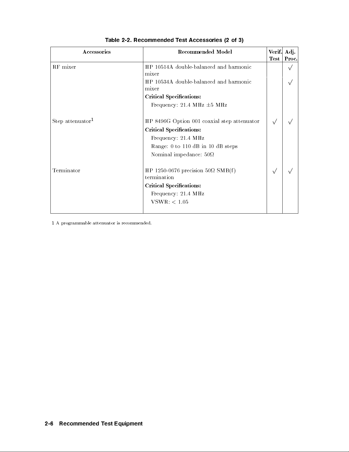
Table 2-2. Recommended Test Accessories (2 of 3)
Accessories Recommended Model Verif.
RF mixer HP 10514A double-balanced and harmonic
mixer
HP 10534A double-balanced and harmonic
mixer
Critical Specications:
Frequency: 21.4 MHz65 MHz
Step attenuator
Terminator HP 1250-0676 precision 50 SMB(f )
1
HP 8496G Option 001 coaxial step attenuator
Critical Specications:
Frequency: 21.4 MHz
Range: 0 to 110 dB in 10 dB steps
Nominal imp edance: 50
termination
Critical Specications:
Frequency: 21.4 MHz
VSWR:<1.05
Test
p p
p p
Adj.
Proc.
p
p
1
A programmable attenuator is recommended.
2-6 Recommended Test Equipment

Table 2-3. Recommended Test Accessories (3 of 3)
Cables and Adapters | Recommended Mo del Verif.
Cables
HP 85680-60093 123 cm (48.4 in) 50 BNC(m) to SMB(f )
HP 10503A 122 cm (48 in) 50 coax BNC(m) to BNC(m)
HP 8120-5016 160 mm (6.3 in) SMB(f ) to SMB(f )
Adapters
HP 1250-1745 50 APC-3.5(f) to N(f )
HP 1251-2277 50 BNC(f) to dual banana plug
HP 1250-1474 precision 50 N(f ) to BNC(f )
HP 1250-1477 precision 50 N(f ) to BNC(m)
HP 1250-1476 precision 50 N(m) to BNC(f )
HP 1250-1473 precision 50 N(m) to BNC(m)
HP 1250-1236 50 SMB(f) to BNC(f )
HP 1250-0672 50 SMB(f) to SMB(f )
HP 1250-0896 50 SMB(m) to BNC(m)
HP 1250-1237 50 SMB(m) to BNC(f )
HP 1250-0674 50 SMB(m) to SMA(f )
HP 1250-0669 50 SMB(m) to SMB(m)
HP 1250-0671 50 SMB(m) to N(m)
HP 1250-1391 50 SMB tee(f ) (m) (m)
Test
p p
p p
p p
p p
p p
p p
p p
p p
p
p p
p
p
p
p
p
p p
p p
Adj.
Proc.
Recommended Test Equipment 2-7

Service Kit
The HP 71000 system service kit is the general service kit for HP 70000 mo dular measurement
system (MMS) mo dules. This kit includes servicing to ols required to repair all MMS modules,
and a mo dication procedure for the HP 70001A mainframe. The mo dication allows access
to MMS mo dules during bench testing and repair.
Table 2-4.
Contents of the HP 71000 system service kit (HP part number 71000-60002)
Quantity Recommended Model
10 HP 2110-0695 1.5A, 125V fuse
10 HP 2110-0700 1.0A, 250V fuse
10 HP 2110-0701 1.6A, 250V fuse
10 HP 2110-0703 6.3A, 250V fuse
10 HP 2110-0710 2.0A, 250V fuse
1 HP 5002-0685 cable puller
1 HP 5021-6773 cable puller
1 HP 5021-7445 pin straightener
7 HP 5061-9021 309 mm (12.2 in) SMB(f ) to SMB(f ) cable
3 HP 85680-60093 123 cm (48.4 in) 50 BNC(m) to SMB(f ) cable
1 HP 70001-00038 modied mainframe cover, right
1 HP 70001-00039 modied mainframe cover, left
1 HP 70001-60013 extender module
1 HP 71000-90015 installation note
2 feet HP 8160-0035 RFI RND STR.0940
10 feet HP 8160-0484 RFI RND BEC.125D
2 feet HP 8160-0495 2.54 x 1.57mm chromeric gasket
1 HP 8710-1651 short 8 mm hex-ball driver
1
1 HP 8710-1728 bandpass lter tuning tool
1 HP 9211-0065 20.5L x 6.5W container
2 HP 9222-0316 bag BR 6.0 x 20.0D
1 HP 9222-0320 bag BR 10.0 x 20.0D
7 HP 9222-1364 bag shield zip 6 x 8
6 HP 9222-1417 bag shield zip 4 x 4
2 HP 9222-1675 bag shield zip AY12
1
An HP 8710-1307 long 8 mm hex-ball driver is also available separately.
2-8 Recommended Test Equipment

21.4 MHz Notch-Filter Documentation
The 21.4 MHz notch lter (HP 70902A Option K01 IF section) can be ordered from
Hewlett-Packard. If you would prefer to build a lter, the following information includes a
schematic diagram, a list of required parts for building the lter, and a gure showing the
typical lter stopband for testing the lter.
Figure 2-1. 21.4 MHz Notch Filter, Schematic Diagram
Table 2-5. 21.4 MHz Notch Filter, Required Parts
Reference
Designation
C1 0160-4800 6 2 Capacitor-Fixed 120 pF 100 V CER
C2 0160-4800 6 Capacitor-Fixed 120 pF 100 V CER
C3 0160-4801 7 1 Capacitor-Fixed 100 pF 100 V CER
J1 1250-0045 5 1 Connector-RF BNC Male
J2 1250-0212 8 1 Connector-RF BNC Female
L1 9100-3548 0 2 Inductor-Fixed 0.47H65%
L2 9100-3548 0 Inductor-Fixed 0.47H65%
L3 9140-0395 3 1 Inductor-Fixed 0.56H65%
HP Part
Number
7100-1040 1 1 Can-Rectangular 1.1823.1
7100-1048 9 1 Cover-Rectangular 1.1223.1
2190-0016 3 4 Washer-Lock 0.377ID
2950-0001 8 2 Nut-Hex 3/8-32
CD Qty Description
Recommended Test Equipment 2-9
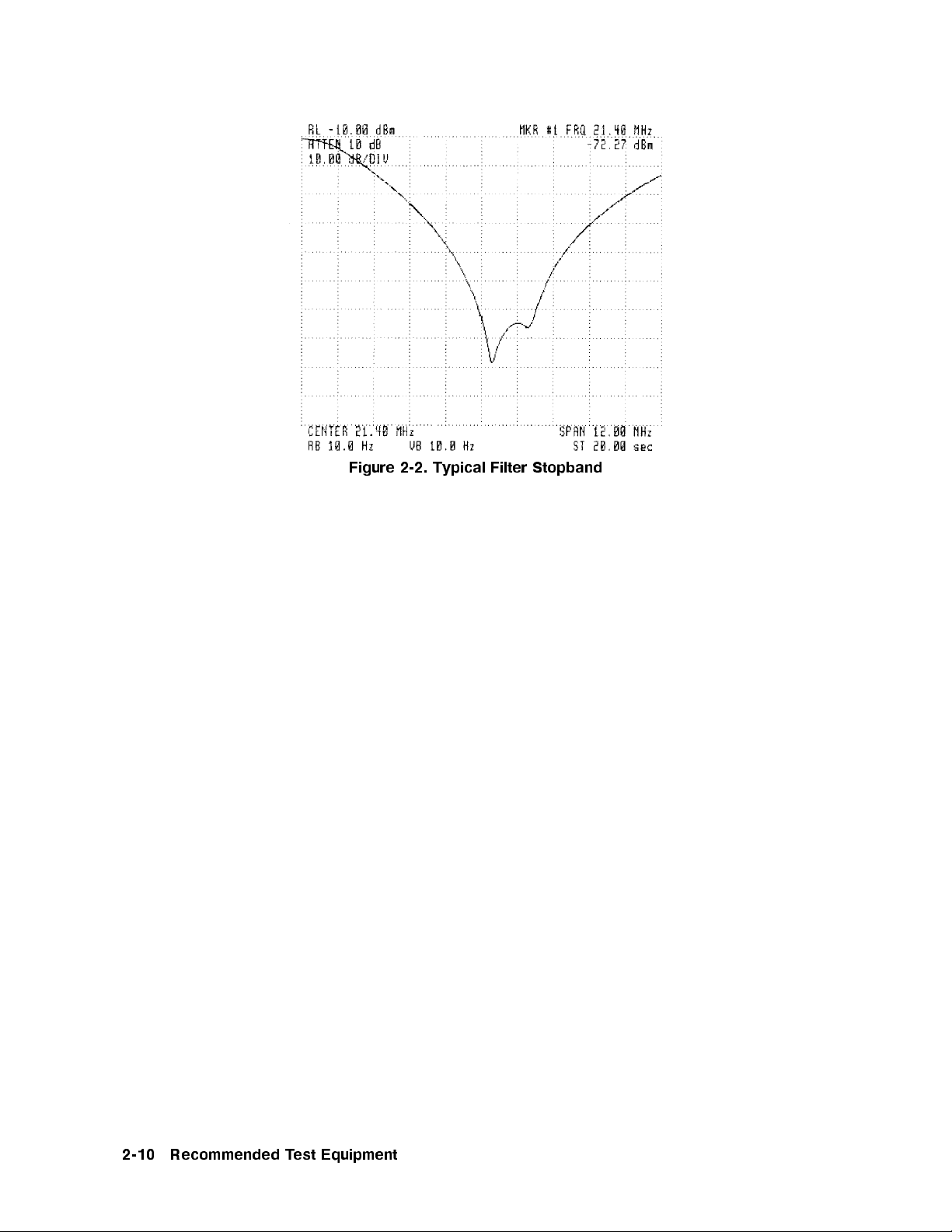
Figure 2-2. Typical Filter Stopband
2-10 Recommended Test Equipment
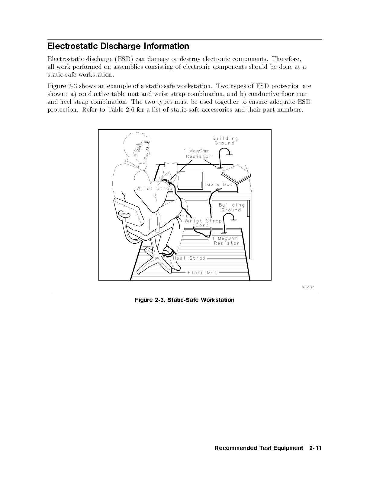
Electrostatic Discharge Information
Electrostatic discharge (ESD) can damage or destroy electronic comp onents. Therefore,
all work performed on assemblies consisting of electronic components should be done at a
static-safe workstation.
Figure 2-3 shows an example of a static-safe workstation. Twotypes of ESD protection are
shown: a) conductive table mat and wrist strap combination, and b) conductive o or mat
and heel strap combination. The twotypes must be used together to ensure adequate ESD
protection. Refer to Table 2-6 for a list of static-safe accessories and their part numbers.
Figure 2-3. Static-Safe Workstation
Recommended Test Equipment 2-11
Reducing ESD Damage
Below are suggestions that may help reduce the amount of ESD damage that occurs during
servicing.
PC Board Assemblies and Electronic Components
Handle these items at a static-safe workstation.
Store or transp ort these items in static-shielding containers.
Caution
PC board assembly edge-connector contacts may be cleaned b
solution of 80% electronics-grade isopropyl alcohol and 20% deionized water. This procedure
should be performed at a static-safe w
Test Equipment
Before connecting any coaxial cable to an instrument connector for the rst time eachday,
momentarily short the center and outer conductors of the cable together.
Personnel should be grounded with a resistor-isolated wrist strap before touc
pin of any connector and before removing any assembly from the instrument.
Be sure that all instruments are properly earth-grounded to prevent buildup of static
charge.
Do not use erasers to clean the edge-connector contacts. Erasers generate
static electricity and degrade the electrical quality of the contacts by
removing the thin gold plating. Do not use paper of any kind to clean the
edge-connector contacts. Paper or lint particles left on the contact surface can
cause intermittent electrical connections. Do not touch the edge-connector
contacts or trace surfaces with bare hands. Always handle b oard assemblies by
the edges.
y using a lint-free cloth with a
orkstation.
hing the center
2-12 Recommended Test Equipment
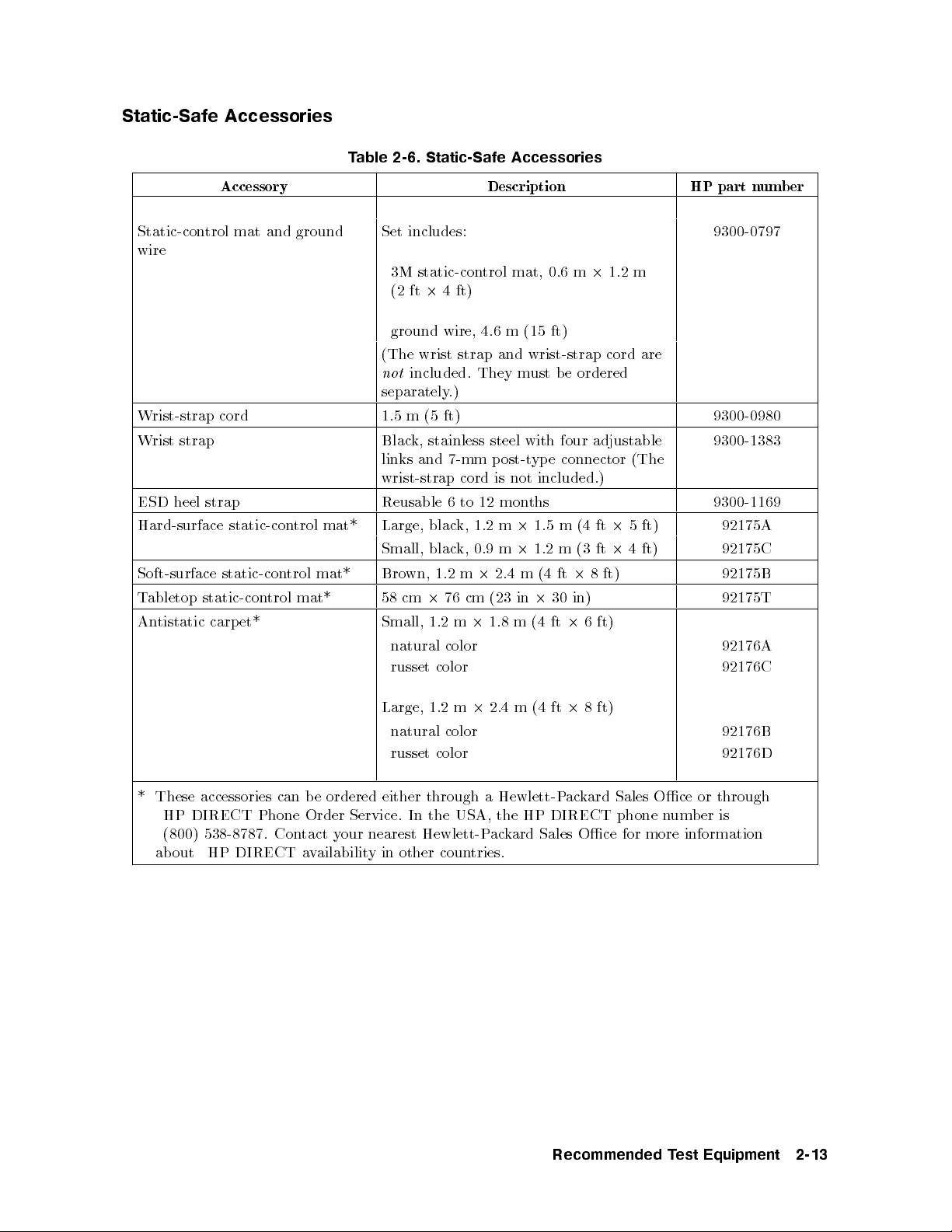
Static-Safe Accessories
Accessory Description HP part number
Table 2-6. Static-Safe Accessories
Static-control mat and ground
Set includes: 9300-0797
wire
3M static-control mat, 0.6 m21.2 m
(2 ft24 ft)
ground wire, 4.6 m (15 ft)
(The wrist strap and wrist-strap cord are
not
included. They must be ordered
separately.)
Wrist-strap cord 1.5 m (5 ft) 9300-0980
Wrist strap Black, stainless steel with four adjustable
9300-1383
links and 7-mm p ost-type connector (The
wrist-strap cord is not included.)
ESD heel strap Reusable 6 to 12 months 9300-1169
Hard-surface static-control mat* Large, black, 1.2 m21.5 m (4 ft25 ft)
Small, black, 0.9 m21.2 m (3 ft24 ft)
Soft-surface static-control mat* Brown, 1.2 m22.4 m (4 ft28 ft)
92175A
92175C
92175B
Tabletop static-control mat* 58 cm276 cm (23 in230 in) 92175T
Antistatic carpet* Small, 1.2 m21.8 m (4 ft26 ft)
natural color 92176A
russet color 92176C
Large, 1.2 m22.4 m (4 ft28 ft)
natural color 92176B
russet color 92176D
* These accessories can be ordered either through a Hewlett-Packard Sales Oce or through
HP DIRECT Phone Order Service. In the USA, the HP DIRECT phone number is
(800) 538-8787. Contact your nearest Hewlett-Packard Sales Oce for more information
about HP DIRECT availability in other countries.
Recommended Test Equipment 2-13

3
Module Verification Software
Module Verication Software is the program designed to automate the mo dule's verication
tests and adjustment pro cedures. Included in this chapter is a step-by-step pro cedure to load
the software and get the verication tests or adjustment pro cedures underway.For more
detailed information, refer to the sections regarding individual menus. Listed below are the
ma jor divisions of this chapter.
General Information
Computer Compatibility
Typographic Conventions
Conguring the Hardware
Installing Verication Software
Module Verication Software Overview
Menus
Error and Status Messages
General Information
This documentation supports module verication software Revision B.03.00 or greater.
Use this software with slave modules that have an HP 70900A/B lo cal oscillator source
as a master. A softkey-driven menu and user-interface screens control the software. The
disks included with this mo dule provide programs that test whether the module meets its
characteristics for system operation.
The
HP 70000 Modular Spectrum Analyzer Instal lation and Verication Manual
contains
conguration information for predened mo dels of HP 70000 Series modular sp ectrum
analyzer systems. The software automatically reads your system conguration data from the
Hewlett-Packard Modular System Interface Bus (HP-MSIB) to determine which system or
modules you are using.
Refer to Chapter 4 and Chapter 5 for individual test setups and test descriptions. Chapter 2
contains a list of recommended test equipment.
Module Verification Software 3-1
Computer Compatibility
Module Verication Software is written in HP 9000 Series 200/300 controller BASIC 4.0 and
can run on the follo wing HP 9000 Series 200/300 controller. Minimum RAM requirementis
2.5 megabytes.
When using an HP 9000 Series 200/300 controller, a medium-resolution monitor and either
an HP 98203C, HP 46020A, or an HP 46021A keyboard is required. Due to the various
keyboards supported, some minor text dierences appear in the menus and softkeys displayed
on-screen. (Refer to \Typographic Conventions").
Computer Language Compatibility
The software program runs on HP BASIC 4.0, or later, with the BIN les in RAM that are
listed below:
CLOCK HPIB
CS80 (optional|supports newer IO
Winchester disk drives) KBD
DISC (optional|supports microoppies MAT
and older Winchester disk drives) MS
ERR PDEV (optional|provides
GRAPH debugging features for
GRAPHX program development)
In a shared resource management (SRM) environment, the following BIN les are also
required:
DCOMM
SRM
A procedure for loading HP BASIC is provided in \Installing Module Verication Software".
Note
If you have set up some RAM memory for sp ecic usage, be a
ware that
this program uses RAM memory Volume \:MEMORY, 0, 15". Moveany
information stored at this Volume to another lo cation before running Mo dule
Verication Software.
Printer Compatibility
Module Verication Software supports any HP-IB printer; however, many of the printed test
results require a graphics printer. Graphical test results are not output to a non-graphics
printer.
3-2 Module Verification Software
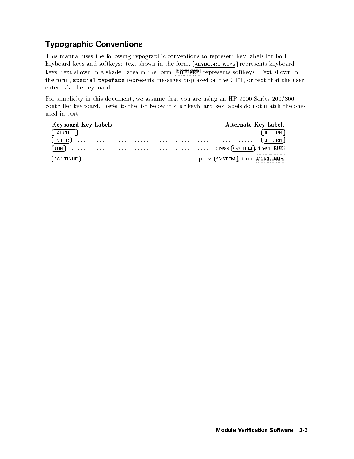
Typographic Conventions
This manual uses the following typographic conventions to representkey labels for both
keyboard keys and softkeys: text shown in the form,
NNNNNNNNNNNNNNNNNNNNNNN
keys; text shown in a shaded area in the form,
the form,
special typeface
represents messages displayed on the CRT, or text that the user
4
KEYBOARD KEYS
SOFTKEY
5
represents keyboard
represents softkeys. Text shown in
enters via the keyboard.
For simplicity in this document, we assume that you are using an HP 9000 Series 200/300
controller keyboard. Refer to the list belowifyour keyboard key lab els do not match the ones
used in text.
Keyboard Key Labels Alternate Key Lab els
4
EXECUTE
4
ENTER
4
RUN
5
.........................................................
5
..........................................................
5
............................................. press
4
SYSTEM
4
4
5
, then
RETURN
RETURN
NNNNNNNNNNN
RUN
5
5
NNNNNNNNNNNNNNNNNNNNNNNNNN
4
CONTINUE
5
.................................... press
4
SYSTEM
5
, then
CONTINUE
Module Verification Software 3-3
Configuring the Hardware
Procedure
1. Connect the HP 70000 Series mo dular spectrum analyzer system to the computer port
determined by the following criteria:
a. For HP 9000 Series 200/300 controllers with an HP 98624A HP-IB interface, connect
your spectrum analyzer to the port lab eled HP-IB SELECT CODE 8. Check that
the address switch on the HP 98624A HP-IB interface matches the HP-IB controller
device address. If needed, refer to the
Installation Guide, Volume 1.
b. For HP 9000 Series 200/300 controllers without an HP 98624A HP-IB interface, connect
the HP 70000 Series mo dular spectrum analyzer system to the port labeled HP-IB
SELECT CODE 7.
2. Connect the HP-IB cables from the test equipment to the computer's HP-IB SELECT
CODE 7 p ort.
3. Use an HP 10833D BNC 0.5 meter HP-IB cable, or similar cable to connect the external
disk drive's HP-IB to the HP-IB SELECT CODE 7 port.
HP 9000 Series 200/300 controller Peripheral
Note
4. Set the external test equipment and the HP 70000 Mo dular sp ectrum analyzer line
switches to ON. Allow the equipmenttowarm up as sp ecied for the verication tests or
adjustment procedures.
5. Turn the disk drive (if used) and computer ON.
Occasionally disk drives exhibit unpredictable b ehavior when sharing the
HP-IB with instruments. If you nd this occurring, assign the disk driv
separate HP-IB select code port.
etoa
3-4 Module Verification Software
Installing Module Verification Software
Use the following steps to get the mo dule verication software loaded and running. Later
sections of this chapter contain more specic program-operation information.
Two assumptions are made with the module verication software. One is that you are using
standard HP-IB addresses for the active devices of the microwave test station. The second
is that all passive devices for the microwave test station are available. If either of these
assumptions is inaccurate, you are prompted for data during program execution.
Software Version
View the version number of the software program after loading the rst program disk. Lo ok in
the right-hand side of the initial display. Specic numbers vary, but the version number lo oks
like this:
Rev. B.01.00
Locate the program part number printed on the disk labels.
Procedure
1. Load BASIC 4.0 or later, with the appropriate binaries, in
to an HP 9000 Series 200/300
controller. If necessary, refer to an HP BASIC reference manual.
Caution
Make backup copies of all write-protected disks. If the program data on an
individual disk should become altered, it cannot be ordered separately
. The
entire set of disks must be ordered to replace any one.
2. Assign the MSI (mass storage is) to the driv
eyou will use as the default drive. As an
example, assigning the MSI to a disk drive lo oks like this:
MSI ":,700,0"
3. Insert Executive Disc into the assigned default drive. Type the following command line:
LOAD "MOD_VERF",1
4. Press
5. If you are using your module's software for the rst time, a message appears stating that
4
EXECUTE
5
. The software version number app ears in the screen that is next displayed.
mass storage data is needed. Press
NNNNNNNNNNNNNNNNNNNNNNN
PROCEED
and follow the on-screen prompts to create a
mass storage data le. Once mass storage data is stored, this message will not reappear.
6. Load the Operating Disc as directed. The Operating Disc probably needs to remain in the
drive specied as the MSI default drive. Load the Driver Discs into the drive sp ecied
on-screen.
An error message may be displayed at this point. If the DUT (device under test) does not
match the module listed in the HP-MSIB Address Map, or if the software you are using
belongs to another mo dule of your system, refer to \Error Messages" at the end of this
chapter to determine a course of action.
7.
Load the Driver Disc as directed. Insert the Driver Disc and press
NNNNNNNNNNNNNNNNNNNNNNN
PROCEED
.
8. If you have not entered serial numbers for passive devices that require calibration data for
test purposes, on-screen prompts request the data no
w. Enter the data via the Calibration
Module Verification Software 3-5

Data screen. Press
CREATE
to access this screen. For a detailed explanation on entering
calibration data, refer to \Edit Calibration Data" in this chapter. Enter the serial number
for each device sp ecied, or bypass the device to continue if it is not used now. After
entering and storing data for passive devices, this prompt screen will not reappear.
NNNNNNNNNNNNNNNNNNNN
Note
In the future, you can access calibration data stored on Operating Discs,
rather than enter the data for passive devices of a given serial number each
time you begin testing. The program displays any additional passive devices
requiring serial numbers and calibration data. Serial numbers are only
required for passive devices that need their calibration data stored on the
Operating Disc. You are prompted to enter serial numbers for these devices
only.
9. You may perform any of the items listed below after satisfying the above conditions:
NNNNNNNNNNNNNNNNNNNNNNNNNNNNNNNN
Select
FINAL TEST
to perform procedures for which the required test equipmentis
present, automatically.
NNNNNNNNNNNNNNNNNNNNNNNNNNNNNNNNNNNNNNNNNNNN
Press
equipment menu
and return to the Equipmen
t Menu. From here you can modify
the status of the equipment in the menu (make it unavailable, readdress it, change the
private bus, etc.). Refer to \Equipment Menu" under \Menu" in this chapter.
NNNNNNNNNNNNNNNNNNNNNNNNNNNNN
Press
test menu
to choose between verication tests or adjustment pro cedures. If
you have already entered either the verication test or adjustment menus, the screen
allowing you to choose one or the other does not reapp ear. T
selection screen, select
NNNNNNNNNNNNNNNNNNNNNNN
press
RESTART
.Beaware that pressing
NNNNNNNNNNNNNNNNNNNNNNNNNNNNN
main menu
from the Test Menu softkeys. In the Main Menu,
NNNNNNNNNNNNNNNNNNNNNNN
RESTART
purges status information for any
o retrieve the Test or Adjust
tests you have already run. You determine individual tests or individual adjustments to
perform via the menuyou select.
NNNNNNNNNNNNNNNNNNNNNNNNNNNNN
Press
MAIN MENU
to customize your test pro cess via any other menu.
3-6 Module Verification Software

Module Verification Software Overview
Testing Multiple Modules
Verication Software tests only one mo dule at a time. If you have more than one module to
test in your system, test them separately.Ifyou have tested a module and wantto change the
module b eing tested without turning o the controller, follow the steps b elow.
1.
Get to the Main Menu, then press
NNNNNNNNNNNNNNNNNNNNNNNNNNNNNNNNNNNNNNNNNNNN
equipment menu
.
2. In the Equipment Menu edit screen, move the item indicator to the Device Model number
column next to the Mo dule Under Test.
NNNNNNNNNNNNNNNNNNNN
3. Press
4.
5.
Press
SELECT
NNNNNNNNNNNNNN
DONE
, modify the model number, and press
NNNNNNNNNNNNNNNNNNNNNNNNNNNNN
, then
main menu
.
4
ENTER
5
.
NNNNNNNNNNNNNNNNNNNNNNNNNNNNN
From the Main Menu, press
under test is
appears, press either
NNNNNNNNNNNNNNNNNNNNNNNNNNNNNNNN
CHANGE DUT
to gain access to the Equipment Menu or HP-MSIB Address Menu. From the
NNNNNNNNNNNNNNNNNNNN
RELOAD
test menu
;
but the software supports the module
.If
ERROR MESSAGE: Selected instrument
and follow the on-screen prompts to load test softw
Equipment Menu, you can select the module under test's model n
are, or
umber and mo dify it to
the module number of the software now loaded. From the HP-MSIB Address Menu, select
the module to test that matches the software you already have loaded. Otherwise, press
NNNNNNNNNNNNNNNNN
ABORT
.
Error Messages or Warnings Defined
There are three kinds of error messages or w
One appears briey at the b ottom of the CR
arnings generated by the program.
T display. The program then go es
automatically to a menu that asks you for corrections or modications.
Another type of error message b egins with
ERROR MESSAGE
and provides special softkeys.
These errors are user-correctable and anticipated by the program. There is usually a
Possible Fix
The nal type begins with
message displayed to help you clear the problem.
ERROR
and provides no sp ecial softkeys. The message informs you
of an unanticipated error. There is no suggested x displayed. If you cannot recover from
one of these errors, please contact your Hewlett-Packard Sales and Service Oce.
Final Tests Defined
Tests dened as Final Tests are a subset of all available verication tests for a given
module. Completing these tests veries a module's electrical p erformance. Once a module
has passed the nal tests, install it into any mainframe and expect performance within its
specied characteristics. Perform tests classied as Additional Tests after troubleshooting
or adjustments to b e sure of the proper operation of sp ecic assemblies. The
NNNNNNNNNNNNNNNNNNNNNNNNNNNNNNNN
FINAL TEST
softkey has no dened purpose while p erforming adjustments.
Module Verification Software 3-7

Single Tests Defined
You may select individual tests with this program. Refer to \Test Menu" under \Menus"
in this chapter for a description of selecting individual tests. As explained in \Final Tests,"
specic assembly performance is checked by running assembly-asso ciated p erformance tests.
Refer to Chapter 6, \Troubleshooting," for a cross-reference of tests to p erform versus
assembly adjusted, repaired, or changed.
Printing Test Results
The program shows whether each pro cedure passed or failed. You may congure the computer
operations to format and print test results via the Parameter Menu. If an HP-IB printer is on
the bus and an address is provided in the Equipment Menu, and you congured the Parameter
Menu to print test results, the program automatically prints the test results. The printout
includes a title and summary page.
The title page lists the following data:
Module software used and the test date
Serial number of the module tested
Firmware version of the mo dule tested
Power line frequency
Test person's identication
Test equipment model numbers and names, addresses, and ID or serial n
umber.
The Summary Page lists total test time b eside the titles of tests p erformed. The Summary
Page also includes test results b eneath one of the follo
Not all Final Tests have been completed
...
wing categories:
etc.
The following Final Tests need to be completed:
The following tests showed insufficient performance:
The following tests met the appropriate requirements:
The following additional tests were not completed:
3-8 Module Verification Software

Menus
Menu Structure
The rst menu presented allows you to go to the Main Menu, to begin Final Tests, or to
return to the Equipment Menu. From the Main Menu, access any of the following menus:
Main Menu
Mass Storage Menu
Parameter Menu
Equipment Menu
Edit Calibration Data
HP-MSIB Address Menu
Test Menu
Except for the Test Menu, these menus are conguration menus through whichyou initialize
the software for program operation. Via these menus, you enter information about disk drives,
environment conditions, test equipment, the mo dule under test, etc. Refer to the information
following the menu name in this c
hapter for details.
In the Test Menu, you select and execute module-related procedures. The T
est Menu provides
some testing options. Refer to \Test Menu" in this chapter for details.
The Mass Storage Menu, the Parameter Menu, and the Equipment Menuhavetwo menu
screens. One is the edit screen, the other is the command screen. (The previously men
tioned
menus use only the command screen.)
In edit screens, you can edit displayed data or input data to the screen.
In command screens, you may perform various menu-specic functions, which include
storing edited data, selecting test mode, accessing the help screen, accessing the Main Men
etc.
Edit and Command Screen Menus
The following softkeys are present for menus that appear in Figure 2-1 through Figure 2-4.
Not all of the menus have edit screens, but all have command screens. When softkey lab els
are written in lowercase letters, a sub-level softkey menu exists for that particular softkey.
Softkey labels written in uppercase letters indicate there no further sub-level softkey menus
exist for that softkey.
Edit Screen Menus
The following softkeys are present for edit menus that appear in Figure 2-1 through Figure
2-4.
NNNNNNNNNNNNNNNNNNNN
SELECT
either one of these keys app ears in the Edit Menu. or
NNNNNNNNNNNNNNNNNNNN
SELECT
activates the column item where the cursor is located,
NNNNNNNNNNNNNNNNNNNNNNNNNNNNNNNNNNNNNNNNN
SELECT TOGGLE
NNNNNNNNNNNNNN
DONE
NNNNNNNNNNNNNNNNNNNNNNNNNNNNNNNNNNNNNNNNN
while
SELECT/TOGGLE
activates predened choices in the menu.
exits the edit screen, then displays the menu's command screen.
u,
Module Verification Software 3-9

Command Screen Menus
The following softkeys are present for the command menus pictured in Figures 2-1 through
2-4. An additional softkey,
NNNNNNNNNNNNNNNNNNNNNNNNNNNNNNNNNNNNNNNNN
edit cal data
, appears only in the Equipment Menu Command
screen. Refer to \Equipment Menu Command Screen" for information about this softkey.
NNNNNNNNNNNNNNNNNNNNNNNNNNNNN
main menu
returns you to the Main Menu. Refer to \Main Menu" for
details.
NNNNNNNNNNNNNN
EDIT
appears if there is an edit screen in the menuyou are working
in. Pressing this key returns you to the menu's edit screen.
NNNNNNNNNNNNNNNNN
STORE
appears if you have data that needs to b e stored on the
OPERATING VOLUME. The HP-IB Address Menudoes
not require this softkey, therefore it do es not appear in that
command menu.
NNNNNNNNNNNNNNNNNNNN
CREATE
appears if you tried to store data without an existing le
available.
NNNNNNNNNNNNNNNNNNNN
CREATE
activates the store function and creates a
le on the OPERATING VOLUME.
NNNNNNNNNNNNNNNNNNNN
REPEAT
appears if the correct Operating Disc con
taining calibration
data is not in the disk drive. This key allows you to insert the
Operating Disc into the disk drive and try again.
NNNNNNNNNNNNNNNNN
ABORT
displays the Main Menu screen. The
for some special task screens, but not in the Main Men
Pressing
NNNNNNNNNNNNNNNNN
ABORT
a time or two returns you to the Main Menu
screen. From the Main Menu, you may press
to BASIC command. If you happen to press
NNNNNNNNNNNNNNNNN
ABORT
softkey is available
u screen.
NNNNNNNNNNNNNN
quit
NNNNNNNNNNNNNNNNN
ABORT
to return
before the
Main Menu is displayed at all, you are prompted to press the
4
5
NNNNNNNNNNNNNN
HELP
key. Press
RUN
pressed
a performance test, the Test Menu appears and oers the
NNNNNNNNNNNNNNNNN
ABORT
NNNNNNNNNNNNNN
selections
accesses menu and softkey descriptions. Listed b elow are
4
RUN
.Ifyou press
quit
or
5
to return to where you were when you
NNNNNNNNNNNNNNNNN
ABORT
NNNNNNNNNNNNNNNNNNNNNNNNNNNNNNNN
or
ABORT TEST
NNNNNNNNNNNNNNNNNNNNNNNNNNNNN
main menu
.
during
softkey selections and functions available via this softkey.
NNNNNNNNNNNNNNNNNNNNNNNNNNNNN
NEXT PAGE
NNNNNNNNNNNNNNNNNNNNNNNNNNNNNNNNNNNNNNNNN
PREVIOUS PAGE
NNNNNNNNNNNNNNNNNNNNNNNNNNNNNNNN
PRINT HELP
NNNNNNNNNNNNNN
DONE
takes you to the top of the next available menu page.
returns you to the top of the preceding menu page.
generates a printout of help-screen information.
returns you to the command or edit screen of the menuyou
were previously in.
NNNNNNNNNNNNNN
quit
NNNNNNNNNNN
YES
displays the quit screen. This softkey is available only from
menu command screens. After you press
if you really want to return to BASIC command. The following
two softkey selections are available via the
stops the program, retains any data les you stored before
pressing
Operating Disc has not been remo
NNNNNNNNNNNNNN
quit
, and returns you to BASIC command. (If the
ved, you can press
NNNNNNNNNNNNNN
quit
,you are asked
NNNNNNNNNNNNNN
quit
softkey.
4
RUN
5
3-10 Module Verification Software

to restart the program and return to the Main Menu. The
program retains all previously entered and stored data.)
NNNNNNNN
NO
displays the edit screen of the previous menu, or the command
screen if there is no edit screen.
Cursor Keys and Menu Selections
When a cursor is present, use either the cursor arrow-keys or the RPG (rotary pulse
generator) knob to position the cursor at the column item you wish to edit.
Note
In most cases, there are more selections available than are displayed
on-screen. Be sure to move the cursor to the right and down as far as you
can.
NNNNNNNNNNNNNNNNNNNNNNNNNNNNN
NEXT PAGE
NNNNNNNNNNNNNNNNNNNNNNNNNNNNNNNNNNNNNNNNN
and
PREVIOUS PAGE
keys are provided to speed your vertical
searches.
Main Menu
From the Main Menu screen you can access all other menus. There is no edit screen for this
menu. Figure 2-1 illustrates the Main Menu softkey organization.
Main Menu Softkeys
Aside from the common softkeys, there are t
One is
NNNNNNNNNNNNNNNNNNNNNNN
RESTART
NNNNNNNNNNNNNNNNNNNNNNNNNNNNNNNNNNN
FINAL TESTS
softkey. Press
, which begins the nal test sequence for a mo dule. The second is the
NNNNNNNNNNNNNNNNNNNNNNN
RESTART
to recongure the program and retest a module, or to
test a dierent mo dule. Pressing this key aects the test status column of b oth the T
Menu edit screen and HP-MSIB address screen. The remaining Main Men
NNNNNNNNNNNNNNNNNNNNNNNNNNNNNNNNNNNNNN
mass storage
in detail in their sections of this c
NNNNNNNNNNNNNNNNNNNNNNNNNNNNNNNNNNNNNNNNNNNN
,
parameter menu
, and
hapter.
If you have stored calibration data on another HP 70000 Soft
wo sp ecial softkeys presented in the Main Menu.
NNNNNNNNNNNNNNNNNNNNNNNNNNNNNNNNNNNNNNNNNNNN
equipment menu
. Each of these menus is explained
u softkeys include
ware Pro duct Operating Disc,
est
replace your current Operating Disc with that one and access the data. Be sure to return the
Operating Disc belonging with your mo dule under test to the default drive.
Mass Storage Menu
The BASIC op erating system can use a number of mass storage devices. These include
internal disk drives, external disk drives, and SRM systems. You are prompted to assign the
areas where the program stores system and operation data. Y
Labels to an msus (mass storage unit sp ecier). An msus is a string expression that poin
ou do this by assigning Volume
ts
to a mass storage lo cation. A mass storage Volume is comp osed of one or more les. Files
are data items or subprograms. A Volume might consist entirely of les on a oppy disk, or
some number of les on a small p ortion of a hard disk. The Mass Storage Men
u lists Volume
Labels that show the lo cation of certain types of program information. These Volume Lab els
are explained b elow.
DATA is where the test results are temporarily stored.
ERROR LOG is where unanticipated errors are recorded for p ossible future use.
OPERATING is where all the program data is stored.
The program retrieves sp ecic information from the following Volume Labels:
Module Verification Software 3-11
SYSTEM contains the Executive Disc 3 program code. There must b e an msus assigned to
this Volume Label.
OPERATING contains the menu les and calibration data.
DRIVER DISC contains the Driver Disc program code. There must b e an msus assigned to
this Volume Label.
TEST DISC contains the module performance test or adjustment procedures programs.
ADJUST DISC contains the module adjustment tests or any applicable adjustment
procedures.
Volume Labels eachhave a default msus. From the Mass Storage Menu, you can reassign the
current msus or directory path designation to another designation. You cannot edit Volume
Labels, but you may edit their msus designations and directory path data elds.
Mass Storage Menu Edit Screen
The Mass Storage Menu softkeys and their functions are described below.
NNNNNNNNNNNNNNNNNNNN
SELECT
NNNNNNNNNNNNNN
DONE
activates the column item where the cursor is located.
exits the edit screen, then displays the Mass Storage Menu
command screen.
1. Use either the keyboard arrow keys or the RPG knob to lo cate the cursor next to the
column item you wish to edit. (Be sure to check column items to the right- or left-hand
side of the CRT, shown by
Press
NNNNNNNNNNNNNNNNNNNN
SELECT
. Key in the new lo cation (msus or Directory P
2.
more
.)
ath). Press
4
ENTER
5
when data
entry for the selected item is complete.
Note
Leave the Directory Path eld blank unless you are using an SRM system, or
HP BASIC 5.0 (or later version) that uses directory path hierarchy.
NNNNNNNNNNNNNN
3. Repeat steps 1 and 2 until you have nished editing. Press
DONE
to display the Mass
Storage Menu command screen.
The Data Volume is predened to use RAM DISC
:MEMORY,0,0"
. If this RAM disk is
not initialized to at least 1040 records, or contains additional les not required by mo dule
verication, BASIC error 64 may occur. Either reinitialize the RAM disk or use the Mass
Storage Menu edit screen to select another medium.
Mass Storage Menu Command Screen
NNNNNNNNNNNNNNNNN
From the command screen, you can press
Menu data for the rst time causes an error message prompting you to create a le. Do this
simply by pressing
NNNNNNNNNNNNNNNNNNNN
CREATE
.
NNNNNNNNNNNNNNNNNNNNNNNNNNNNN
Next, press
main menu
to return to the Main Menu screen, or Press
STORE
to save the edited data. Saving Mass Storage
NNNNNNNNNNNNNN
EDIT
and return to the
Mass Storage Menu edit screen.
3-12 Module Verification Software
Parameter Menu
You may determine some operating conditions of the software program in the Parameter
Menu. You can select the printer and its output parameters, decide whether you want the
program beep feature on or o, include a message on the test-results output, etc. Use the
NNNNNNNNNNNNNNNNNNNNNNNNNNNNNNNNNNNNNNNNN
SELECT/TOGGLE
softkey to select the parameter item and enter data, or toggle to a predened
state. The parameter items and their appropriate selections are dened below.
Parameter Menu Edit Screen
NNNNNNNNNNNNNNNNNNNNNNNNNNNNNNNNNNNNNNNNN
Results sent to: Your choices are Screen or Printer. Press
When
When
Screen
Printer
is displayed, the test results appear on the CRT.
is displayed, test results are displayed on-screen
SELECT/TOGGLE
and printed out.
Output Format:
Your choices are Graph or Table. Press
When
Graph
is displayed, test results are generated in a graph
NNNNNNNNNNNNNNNNNNNNNNNNNNNNNNNNNNNNNNNNN
SELECT/TOGGLE
.
format if appropriate for the particular test results (a graphics
printer is required if
When
Table
is displayed, the test results are output in a table
Printer
and
Graph
are both selected).
format.
NNNNNNNNNNNNNNNNNNNNNNNNNNNNNNNNNNNNNNNNN
Printer Lines: Lines allo wed are from 50 to 70. Press
anumber from 50 to 70 to set the n
SELECT/TOGGLE
.Enter
umber of lines per printed
page.
.
Line Frequency: Valid frequency selections are 50, 60, and 400 Hz. Press
NNNNNNNNNNNNNNNNNNNNNNNNNNNNNNNNNNNNNNNNN
SELECT/TOGGLE
until the power line frequency for your system
is displayed. The line frequency value aects some test results.
Beeper to be activated:
Your choices are Yes or No. Press
NNNNNNNNNNNNNNNNNNNNNNNNNNNNNNNNNNNNNNNNN
SELECT/TOGGLE
. When
is displayed, the warning and time-lapse reminder b eeps are
activated. WhenNois displayed, the program's b eep feature is
disabled.
NNNNNNNNNNNNNNNNNNNNNNNNNNNNNNNNNNNNNNNNN
Verify equipment on HP-IB: Your choices are Yes or No. Press
your choice.
Yes
causes the program to verify the presence
SELECT/TOGGLE
to indicate
of each instrument on HP-IB at the address shown in the
Equipment Menu. SelectNoto bypass this feature.
Test person's ID:
NNNNNNNNNNNNNNNNNNNNNNNNNNNNNNNNNNNNNNNNN
Press
SELECT/TOGGLE
, then enter your name or ID number to
include it on the output report.
Number lines added: Lets you include a printed message with the test results.
Depending on the program, you can enter up to 30 lines, with
no more than 30 characters p er line. Enter the message you
wish to have printed in this screen by selecting User Line.
User Line: 1. Position the cursor to the left-hand side of a User Line in
the menu. Press
2. The prompt,
NNNNNNNNNNNNNNNNNNNNNNNNNNNNNNNNNNNNNNNNN
SELECT/TOGGLE
.
Enter additional information
, app ears.
Type in your message (up to 30 characters per line), then
press
4
ENTER
5
.
Yes
Module Verification Software 3-13
3. After you haveentered your message, reposition the cursor
at
Number lines added:
your message o ccupies, then press
Parameter Menu Command Screen
NNNNNNNNNNNNNN
Press
displayed is the command screen. Press
NNNNNNNNNNNNNN
DONE
when you are nished with the Parameter Menu edit screen. The next screen
EDIT
to return to the edit screen, or
NNNNNNNNNNNNNNNNNNNNNNNNNNNNN
NNNNNNNNNNNNNNNNN
STORE
main menu
.Enter the number of user lines
4
ENTER
5
.
to saveany edited Parameter Menu data,
to return to the Main Menu screen.
Saving Parameter Menu data for the rst time causes an error message. The message prompts
you to create a le. Do this simply by pressing
NNNNNNNNNNNNNNNNNNNN
CREATE
.
Equipment Menu
The Equipment Menu edit screen displays a list of all the equipment required to test your
DUT completely. Next to each DEVICE TYPE in the equipment list is a column labeled
DEVICE MODEL for the mo del number, ADDRESS for the HP-IB address, SERIAL or ID
NO. (for example, calibration lab number), and PRIVATE BUS for private bus designation (as
for the HP 8756A scalar network analyzer, HP 8757A scalar network analyzer, and HP 8757C
scalar network analyzer, etc.).
Using preferred mo dels of test equipment, describ ed in Chapter 2, assures the most complete
verication and adjustment testing. Refer to the verication tests and adjustment procedures
in this manual for individual test descriptions and test setups.
Equipment Menu Edit Screen
From the Equipment Menu edit screen you can enter data about your test equipment. You
cannot edit the DEVICE TYPE column.
You may use either the cursor arrowkeys or the RPG knob to p osition the cursor at the
column item you wish to edit.
1. Edit a DEVICE MODEL item by locating the cursor b eside the model n
edit. Press
NNNNNNNNNNNNNNNNNNNN
SELECT
,type the mo del number, then press
4
ENTER
5
.
umber you wish to
2. Edit an ADDRESS by lo cating the cursor b eside the address you want to edit. Press
NNNNNNNNNNNNNNNNNNNN
SELECT
, edit the address, then press
If the DEVICE MODEL has no address in the ADDRESS column,
4
ENTER
5
.
Missing ETE
included in the Status column next to the tests that required the device. T
with
Missing ETE
are not performed.
is
ests tagged
Valid active device addresses are restricted to the following ranges:
700 to 730 and 800 to 830 for an HP 70000 Modular spectrum analyzer master module
700 to 730 for any other device typ e
These three-digit HP-IB address include the HP-IB select co de and the actual HP-IB
address. For example, an HP 70000 Modular spectrum analyzer HP-IB select code of
8 and an HP-IB address of 21 yields an address of 821. The addresses of DUTs that
function as slaves should match their master device's address.
3-14 Module Verification Software
Address passive devices (non-programmable devices such as sensors, directional bridges,
and detectors) as either
entering
Available
AvailableorNot Available
.For some of the passive devices,
in the address column requires entering calibration data and a serial
number for the device. The calibration data for a passive device is stored on Op erating
Discs.
Passive devices tagged
Not Available
in the address column cause
Missing ETE
to be
printed next to the test names on the test results that are output for any pro cedure that
required the missing device. Tests tagged with
3.
Edit a SERIAL NUMBER by lo cating the cursor b eside the serial number. Press
enter the new serial number (10 digits or less), then press
that have
Available
displayed in the address column must also have a serial-number entry.
Missing ETE
4
ENTER
are not p erformed.
5
. Some passive devices
NNNNNNNNNNNNNNNNNNNN
SELECT
4. Enter 19 in the PRIVATE BUS column if you are to use a MicrowaveorFull Microwave
source with a network analyzer. Congure these instruments by connecting the source's
HP-IB cable to the network analyzer's SYSTEM INTERFACE connection.
a. Move the cursor through the DEVICE TYPE column until you reach the Full
Microwave or Microwave source, then move horizontally to the PRIVATE BUS column.
b. Enter19and press
selected source when 19 app ears in the PRIV
4
ENTER
5
. The program enters the ADDRESS column data for the
ATE BUS column. Nineteen is the only
allowable address for sources on a private bus. Refer to the network analyzer's manual
for addressing information.
Equipment Menu Command Screen
NNNNNNNNNNNNNN
After you have nished editing the Equipment Menu, press
Menu command screen. Press
Saving Equipment Menu data for the rst time generates an error message prompting y
create a le. Do this simply by pressing
NNNNNNNNNNNNNNNNN
STORE
to save the edited data.
NNNNNNNNNNNNNNNNNNNN
CREATE
.
DONE
to enter the Equipment
ou to
,
This command screen displays the following additional softkeys:
NNNNNNNNNNNNNNNNNNNNNNNNNNNNNNNNNNNNNNNNN
edit cal data
displays the Select Passive Device screen. From this screen, move
the cursor to the passive device that needs its calibration data
edited. Press
Calibration Data
NNNNNNNNNNNNNNNNNNNN
SELECT
, then enter the required data. Refer to
for more information.
Edit
NNNNNNNNNNNNNNNNNNNNNNNNNNNNNNNN
NO ADDRESS
appears only if the program cannot nd an instrumen
t at a specied
HP-IB address. Tocheck which instruments are not resp onding, follow
the steps below.
1. Access the Equipment Menu edit screen.
2. Scroll the ADDRESS column for ashing addresses, then be sure that the instrument is on.
NNNNNNNNNNNNNNNNNNNN
3.
SELECT
the ashing address and either correct the address or press
NNNNNNNNNNNNNNNNNNNNNNNNNNNNNNNN
NO ADDRESS
to delete
the fault-address from the edit menu.
Note
Either exiting the Equipment Menuorentering the Test Menu causes the
program to search the addresses in the Equipment Menu for instruments
assigned to HP-IB, if this feature is selected in the P
arameter Menu.
Module Verification Software 3-15
4. Press
main menu
to return to the Main Menu, or
data for passive devices. Pressing
NNNNNNNNNNNNNNNNNNNNNNNNNNNNN
NNNNNNNNNNNNNNNNNNNNNNNNNNNNNNNNNNNNNNNNN
edit cal data
NNNNNNNNNNNNNNNNNNNNNNNNNNNNNNNNNNNNNNNNN
edit cal data
to enter calibration
displays the Select Passive Device
screen. Refer to the following section for more information.
Edit Calibration Data
The Select Passive Device screen displays all passive devices needing calibration data entered.
NNNNNNNNNNNNNNNNNNNNNNNNNNNNNNNNNNNNNNNNN
Press
edit cal data
to enter the Select Passive Device screen. The program requires
calibration data for some of the passive devices listed in the Equipment Menu edit screen.
Note
Selecting a passive device needing a serial number generates a prompt
requesting that you enter the number via the Equipment Menu. If you have
formerly entered calibration data for a passive device of a given serial number
and you would rather not reenter the data, replace your current Operating
Disc with one containing data for passive devices from previous testing. Press
NNNNNNNNNNNNNNNNNNNN
REPEAT
to access the calibration data from that disk. If you only need to
enter the passive device's calibration data, press
Calibration Data screen, then b egin at step 4.
NNNNNNNNNNNNNNNNNNNN
1. Locate the cursor beside the device and press
you to delete or edit data related to the passiv
Note
Not all frequencies are listed on the screen at once. Be sure to en
SELECT
e device.
. The next screen displayed allows
calibration data for frequencies listed on the next pages of the displa
2. If you edit the factory default FREQUENCY or CAL F
calibration factors for each frequency edited.
Note
You must enter a frequency and calibration factor for 10 MHz and 300 MHz,
even if the device has no factor listed at 10 MHz or 300 MHz. En
values from the list of valid factors, below. Other frequencies outside the
normal range of the device may also be required. Prior to using your
device, you may need to calibrate it at these frequencies to ensure accurate
measurement results.
NNNNNNNNNNNNNNNNNNNN
CREATE
to enter the Edit
ter
y.
ACTORS values, enter valid
ter the
Passive Device Calibration Factors
Mixers . ....................................................... 16 to 24 dB
Directional Couplers ............................................. 8 to 11 dB
Noise Sources . . . . . . ............................................ 12 to 16 dB
Sensors ..................... 0.3 to 1.6
(stored as a p ercentage by the program)
Edit Calibration Data Edit Screen
NNNNNNNNNNNNNNNNNNNN
1. Move the cursor to a column item and press
calibration factor, then press
4
ENTER
5
. (It is not necessary to enter new frequency values in
SELECT
.Enter the new frequency or
numeric order. The program sorts them before storing them on the Operating Disc.)
3-16 Module Verification Software

2.
To delete an item, move the cursor to the column item. Press
NNNNNNNNNNNNNNNNNNNN
SELECT
, clear the line, then
move to another item. Repeat the above pro cess as needed to edit frequency values or
calibration data for any passive devices.
Edit Calibration Data Command Screen
NNNNNNNNNNNNNN
1. After you haveentered the necessary data, press
DONE
. The Equipment Menu command
screen is displayed.
2.
From the command screen, you can press
NNNNNNNNNNNNNNNNNNNNNNNNNNNNN
main menu
when you are ready to continue with
the program.
HP-MSIB Address Menu
The HP-MSIB Address Menu lists the names and HP-MSIB addresses of the modules in
the HP 70000 Series mo dular spectrum analyzer system that you may select to test. The
HP-MSIB address of the master and the system are the same. In other words, the address of
the master mo dule determines the address of the system. For information on conguring the
software to test a specic module, refer to
Equipment Menu
in this chapter.
NNNNNNNNNNNNNNNNNNNNNNNNNNNNNNNNNNNNNNNNN
There is no edit screen for this menu. The command screen has a
but requires no
NNNNNNNNNNNNNNNNNNNNNNNNNNNNNNNNNNNNNNNNN
SELECT MODULE
NNNNNNNNNNNNNNNNN
STORE
softkey. Locate the cursor next to the module y
. Be sure the mo dule selected here matc
hes the
SELECT MODULE
ou wish to test. Press
Module Under Test
softkey
listed in
the Equipment Menu.
Test Menu
NNNNNNNNNNNNNNNNNNNNNNNNNNNNN
Pressing
If
ERROR MESSAGE: The is listed as the DUT in the Equipment Menu, but the
suggests you select either
test menu
is selected in the HP-MSIB Address Menu
from the Main Menu screen accesses the Test or Adjust selection screen.
NNNNNNNNNNNNNNNNNNNNNNNNNNNNNNNNNNNNNNNNN
MODIFY MODULE
to enter new ROM data or
appears, the possible x information
NNNNNNNNNNNNNNNNNNNNNNNNNNNNNNNN
CHANGE DUT
to select
the module you wish to test.
NNNNNNNNNNNNNNNNNNNNNNNNNNNNNNNNNNNNNNNNN
If you press
number to the module you want to test. If you press
MODIFY MODULE
, on-screen commands help you change the model and serial
NNNNNNNNNNNNNNNNNNNNNNNNNNNNNNNN
CHANGE DUT
, go either to the Equipment
Menutochange the model number or to the HP-MSIB Address Map to select the module
number you want to test.
To begin the testing process, select
adjustments pro cedures. Press
NNNNNNNNNNNNNNNNNNNNNNNNNNNNN
main menu
NNNNNNNNNNNNNN
TEST
to run verication tests or
to return to the Main Menu.
NNNNNNNNNNNNNNNNNNNN
ADJUST
to perform
Module Verification Software 3-17
If you have pressed
NNNNNNNNNNNNNNNNNNNNNNNNNNNNN
main menu
NNNNNNNNNNNNNNNNNNNNNNN
,
RESTART
FINAL TEST
NNNNNNNNNNNNNNNNNNNNNNNNNNNNN
,
TEST MENU
, and wish to get to the adjustment procedures, press
, then
NNNNNNNNNNNNNNNNNNNN
ADJUST
and want to get to the verication tests, press
NNNNNNNNNNNNNNNNNNNNNNNNNNNNNNNN
.Ifyou are in the adjustment pro cedures
NNNNNNNNNNNNNNNNNNNNNNNNNNNNN
main menu
NNNNNNNNNNNNNNNNNNNNNNN
,
RESTART
NNNNNNNNNNNNNNNNNNNNNNNNNNNNN
,
TEST MENU
, then
NNNNNNNNNNNNNN
TEST
.
Caution
Pressing either
NNNNNNNNNNNNNNNNNNNNNNN
RESTART
NNNNNNNNNNNNNNNNNNNNNNNNNNNNNNNNNNNNNNNNNNNN
or
equipment menu
any time after testing begins
purges Test Menu Status column information. Selecting a new module to
test in the HP-MSIB Map Screen Menu also deletes the Status column data.
The assumption is that verication-test status will most likely be modied if
you are moving between modules, ETE mo del numbers, or to the adjustment
procedures.
After selecting
Tests
, the names of the verication tests are displayed. Review the Status
column for tests performed.
Additional test equipment is required to perform tests b eside which
review which additional test equipment is required, locate the cursor beside the test name,
then press
NNNNNNNNNNNNNNNNNNNNNNNNNNNNNNNNNNN
SINGLE TEST
. The Missing ETE screen displays the missing test equipment for
Missing ETE
is listed. To
that test.
A message stating that calibration data for passive devices is missing may also app ear. If the
correct Operating Disc is in the default driv
to build the data le. After the problem is cleared, the T
e, store the calibration data there. Press
est Menu is displayed.
NNNNNNNNNNNNNNNNNNNN
CREATE
3-18 Module Verification Software
Test Menu Command Screen
The Test Menu only has a command screen. It deviates from the command screen formats
previously described. The following list denes the softkeys available in this menu.
NNNNNNNNNNNNNNNNNNNNNNNNNNNNNNNN
FINAL TEST
begins the nal test sequence. Final tests are the ones required
to verify module operation. There are additional tests that can
be selected as well. (Review the Test MenuTest Name list for all
available tests.) During the nal test sequence, the keys listed below
are also available.
NNNNNNNNNNNNNNNNNNNNNNNNNNNNNNNNNNNNNN
END SEQUENCE
interrupts the test sequence at the end of the test in progress.
The Test Menu is displayed with an additional softkey labeled
NNNNNNNNNNNNNNNNNNNNNNNNNNNNNNNNNNNNNNNNNNNN
RESUME TESTING
. Press this key to resume the test sequence where
the program left o.
NNNNNNNNNNNNNNNNN
ABORT
ends the testing process and displays the Test Menu. From there you
maychoose some other action.
NNNNNNNNNNNNNNNNNNNNNNNNNNNNNNNNNNNNNNNNNNNN
RESUME TESTING
NNNNNNNNNNNNNNNNNNNNNNNNNNNNNNNNNNN
SINGLE TEST
allows you to continue the nal test sequence after you have pressed
NNNNNNNNNNNNNNNNNNNNNNNNNNNNNNNN
FINAL TEST
followed by
lets you select an individual test to run. If
the Status column, you can review which test equipment is missing.
Locate the cursor b eside that test name, then press
NNNNNNNNNNNNNNNNNNNNNNNNNNNNNNNNNNNNNN
END SEQUENCE
.
Missing ETE
is listed in
NNNNNNNNNNNNNNNNNNNNNNNNNNNNNNNNNNN
SINGLE TEST
The Missing ETE screen is displayed. If you choose to return to the
Test Equipment Menu via the Test Menu to install the missing test
equipment, you lose the status of any tests that have run. To run a
NNNNNNNNNNNNNNNNNNNNNNNNNNNNNNNNNNNNNNNNN
multiple test
single test that has the necessary ETE, locate the cursor b eside the
test name and press
softkey lets you organize a group of tests sequentially. Locate the
cursor beside the test you want to run. Press
rst number of the series to that test. Con
and press
Press
NNNNNNNNNNNNNNNNNNNN
SELECT
NNNNNNNNNNNNNNNNNNNNNNNNNN
END LIST
NNNNNNNNNNNNNNNNNNNNNNNNNNNNNNNNNNN
SINGLE TEST
.
NNNNNNNNNNNNNNNNNNNN
SELECT
to assign the
tinue to locate the cursor
until you have organized the tests you want to run.
when you are ready to b egin testing. During testing,
the following softkeys are also available.
NNNNNNNNNNNNNNNNNNNNNNNNNNNNNNNNNNNNNN
END SEQUENCE
interrupts the test sequence at the end of the test in progress, then
displays the Test Menu.
NNNNNNNNNNNNNNNNN
ABORT
ends the testing process and displays the Test Menu. From there you
maychoose some other action.
NNNNNNNNNNNNNNNNNNNNNNNNNNNNNNNNNNNNNN
repeat mult.
softkey allo ws you to select a test sequence (you determine the
quantity and order). The tests loop through this sequence until you
decide to stop them. Locate the cursor beside the test you wantto
run, press
NNNNNNNNNNNNNNNNNNNN
SELECT
,move the cursor to the next test, press
NNNNNNNNNNNNNNNNNNNN
SELECT
etc. Continue selecting tests until you are ready to begin testing.
It is acceptable to select the same test for repeated testing. Press
NNNNNNNNNNNNNNNNNNNNNNNNNN
END LIST
to start the test sequence. During testing, the following
softkeys are also available.
NNNNNNNNNNNNNNNNNNNNNNNNNNNNNNNNNNNNNN
END SEQUENCE
interrupts the test sequence at the end of the test in progress, then
displays the Test Menu.
.
,
Module Verification Software 3-19
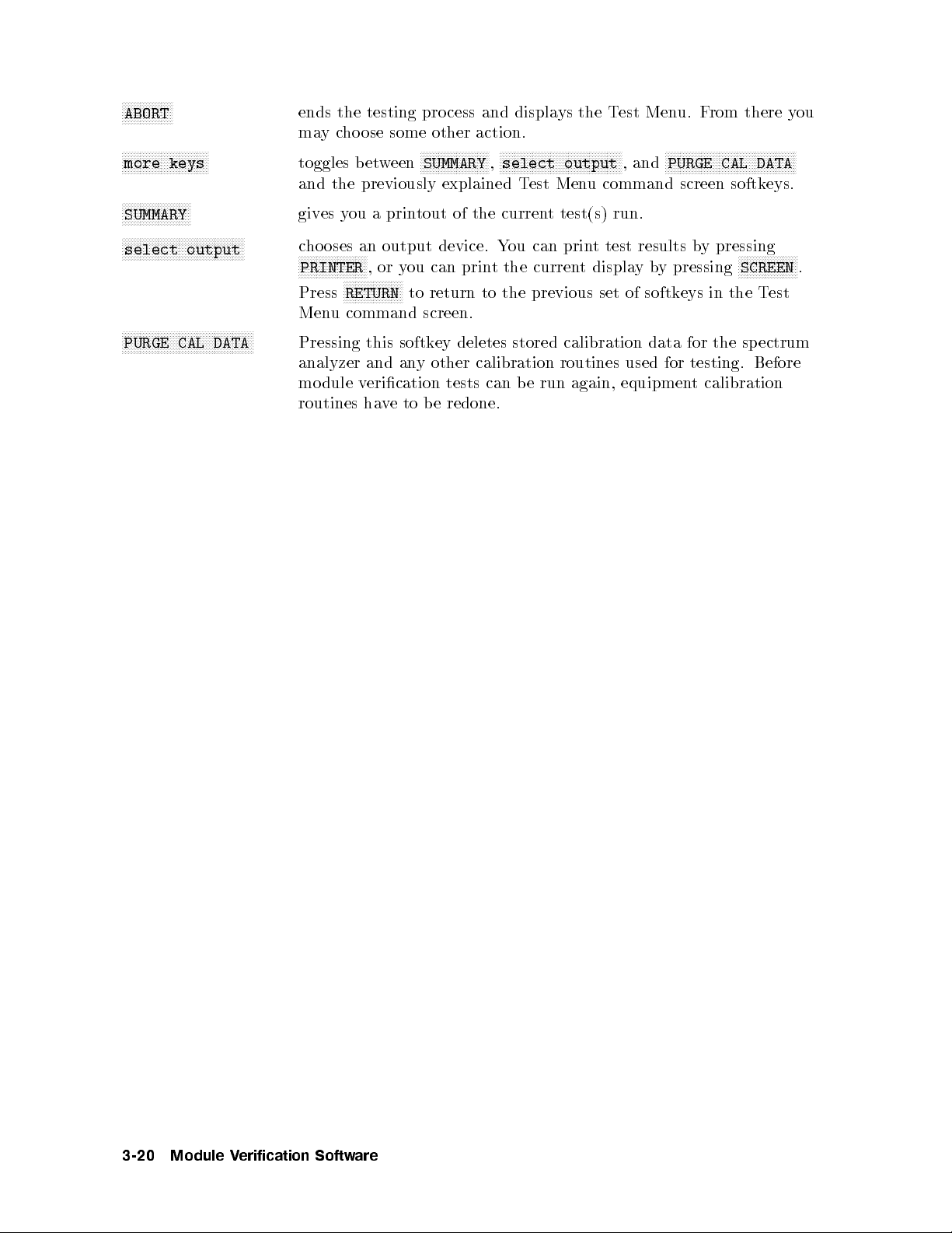
NNNNNNNNNNNNNNNNN
ABORT
NNNNNNNNNNNNNNNNNNNNNNNNNNNNN
more keys
NNNNNNNNNNNNNNNNNNNNNNN
SUMMARY
NNNNNNNNNNNNNNNNNNNNNNNNNNNNNNNNNNNNNNNNN
select output
NNNNNNNNNNNNNNNNNNNNNNNNNNNNNNNNNNNNNNNNNNNN
PURGE CAL DATA
ends the testing process and displays the Test Menu. From there you
maycho ose some other action.
toggles between
NNNNNNNNNNNNNNNNNNNNNNN
SUMMARY
NNNNNNNNNNNNNNNNNNNNNNNNNNNNNNNNNNNNNNNNN
,
select output
NNNNNNNNNNNNNNNNNNNNNNNNNNNNNNNNNNNNNNNNNNNN
, and
PURGE CAL DATA
and the previously explained Test Menu command screen softkeys.
gives you a printout of the current test(s) run.
chooses an output device. You can print test results by pressing
NNNNNNNNNNNNNNNNNNNNNNN
PRINTER
NNNNNNNNNNNNNNNNNNNN
Press
RETURN
,oryou can print the current displayby pressing
to return to the previous set of softkeys in the Test
NNNNNNNNNNNNNNNNNNNN
SCREEN
.
Menu command screen.
Pressing this softkey deletes stored calibration data for the spectrum
analyzer and any other calibration routines used for testing. Before
module verication tests can b e run again, equipment calibration
routines have to be redone.
3-20 Module Verification Software
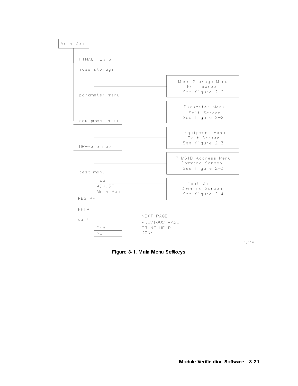
Figure 3-1. Main Menu Softkeys
Module Verification Software 3-21

Figure 3-2. Mass Storage Menu and Parameter Menu Softkeys
3-22 Module Verification Software
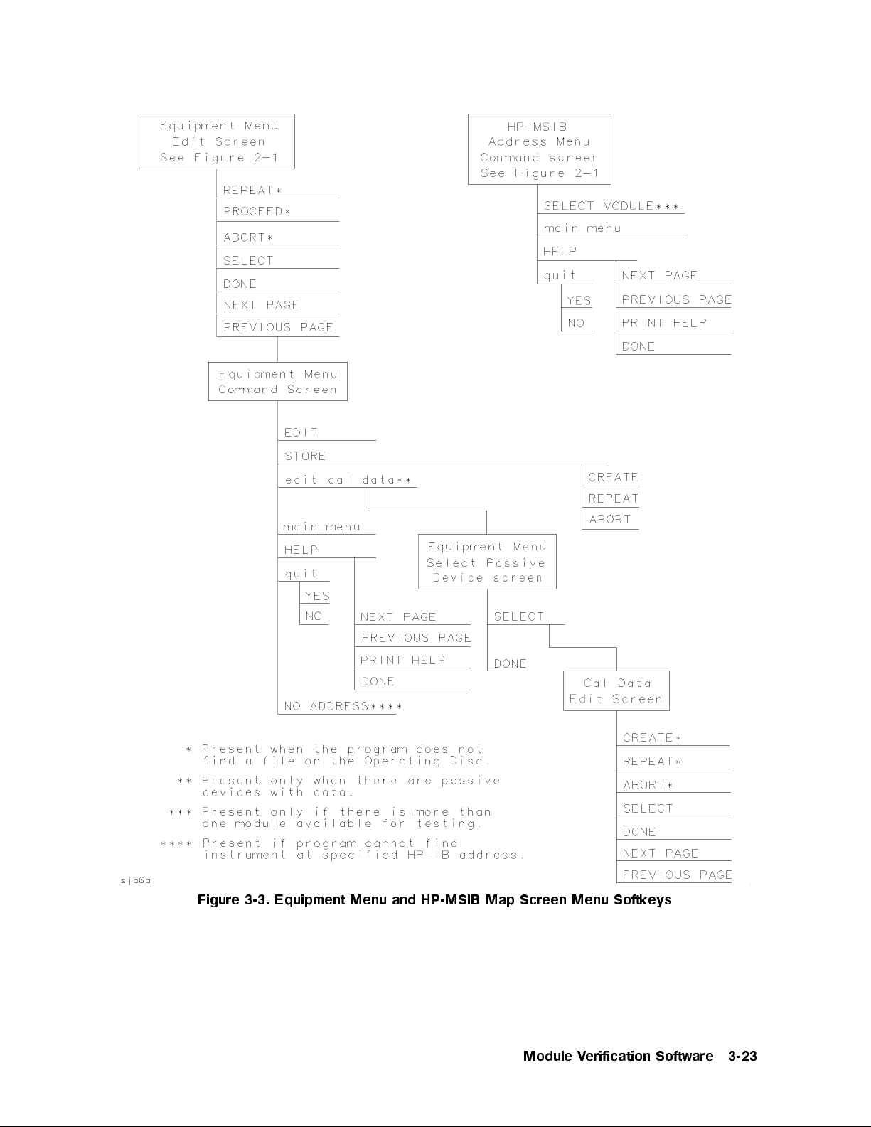
Figure 3-3. Equipment Menu and HP-MSIB Map Screen Menu Softkeys
Module Verification Software 3-23

Figure 3-4. Test Menu Softkeys
3-24 Module Verification Software

Error and Status Messages
User interface messages used with HP 70000 Series software products are alphabetized in
this section. The messages are designed to provide information about test results, op erator
errors, system conditions, etc. Refer to your
HP BASIC Language Reference
for system error
information.
Aborted
You aborted the test indicated.
EEPROM for is defective.
The EEPROM needs to be replaced.
Failed
The module under test needs adjustment or repair to pass the test number indicated.
CAUTION: Passthru address is incorrect. (See Edit Screen).
The address of the microwave source is not set to 19, or the address specied in the
Equipment Menu do es not match the address of the synthesized source. Return to the
edit screen of the Equipment Menu to modify addresses in either the address column or
the private bus column.
CAUTION: Some Model #'s are not supported. (See Edit Screen).
You have model numbers in the Equipment Menu that are not supported by the software.
Ignore this caution if you are sure program memory contains a driver for these mo dels.
A driver that is required but missing causes the error message
subprogram
to appear on-screen. You are returned to the Test Menu.
Undefined function or
Equipment list is not acceptable.
You attempted to enter the Test Menu, but the program could not locate all the
instruments for whichyou have specied HP-IB addresses. Verify that the indicated
equipment is turned on, then return to the Equipmen
accuracy of addresses that are ashing in either the address column or the priv
t Menu edit screen to verify
ate bus
column.
Equipment list shows no analyzer to test.
The DUT has no assigned HP-IB address. Return to the Equipment Menu and edit the
Address column.
ERROR: Address matches system disc drive
.
You entered an HP-IB address matching that of the computer's external disk drive.
HP-IB proto col allows only one instrument per address.
ERROR: Address not in acceptable range.
You entered an HP-IB address outside the range 700 to 730, inclusive.
ERROR: Duplicate HP-IB address.
You attempted to exit the Equipment Menu after assigning the same HP-IB address to
dierent mo del numbers. HP-IB proto col allows only one instrument p er address. (It is
acceptable to assign the same address to identical mo del numbers.)
Module Verification Software 3-25

ERROR: Non-responding HP-IB address
.
You attempted to exit the Equipment Menu after assigning an HP-IB address to an
instrument not responding on HP-IB.
ERROR: Search for unsuccessful.
The program tried to nd the disk identied but could not. Either assign a driveto
the disk and press
NNNNNNNNNNNNNNNNNNNN
REPEAT
.
NNNNNNNNNNNNNNNNNNNN
REPEAT
or insert the required disk into its appropriate drive. Press
ERROR: Some devices listed as Available require serial numbers.
NNNNNNNNNNNNNNNNNNNNNNNNNNNNNNNNNNNNNNNNN
You pressed
View Cal Data
, then selected a device to whichyou have not assigned a
required serial number. Display the Equipment Menu edit screen and assign the serial
number.
ERROR MESSAGE: Address is HP-IB controller address.
You entered an HP-IB address matching the computer's address. HP-IB protocol allows
only one instrument per address.
ERROR MESSAGE: Attempt to close file failed.
There is a problem with the data le on the Op erating Disc. Correct the problem, then
do one of the following:
NNNNNNNNNNNNNNNNNNNN
Press
REPEAT
to try again.
NNNNNNNNNNNNNNNNNNNN
Press
CREATE
to create a new le.
NNNNNNNNNNNNNNNNN
Press
ABORT
to return to the Main Menu.
ERROR MESSAGE: Attempt to create file failed.
There is a problem with the data le on the Op erating Disc. Correct the problem, then
do one of the following:
NNNNNNNNNNNNNNNNNNNN
Press
REPEAT
to try again.
NNNNNNNNNNNNNNNNNNNN
Press
CREATE
to create a new le.
NNNNNNNNNNNNNNNNN
Press
ABORT
to return to the Main Menu.
ERROR MESSAGE: Attempt to Edit Mass Storage failed.
Your edits to the Mass Storage Menuwere not valid. Return to this menu and correct the
errors.
ERROR MESSAGE: Attempt to store Mass Storage failed.
You pressed
NNNNNNNNNNNNNNNNN
Press
ABORT
NNNNNNNNNNNNNNNNN
ABORT
after pressing
to return to the Main Menu.
NNNNNNNNNNNNNNNNN
STORE
mass storage. The Mass Storage Menu failed.
ERROR MESSAGE: Bad instrument address in equipment list. Address matches
controller.
You entered an HP-IB address matching that of the controller. HP-IB protocol allows
only one instrument per address and only one controller per HP-IB system. (The factory
preset controller address is 21.)
3-26 Module Verification Software

ERROR MESSAGE: Calibration data frequency exceed acceptable limits.
Return to the Calibration Data edit screen and correct the data entries that are ashing.
ERROR MESSAGE: Calibration data frequency is less than minimum range of
The frequency entered next to the device in the Cal Data edit screen is out of the device's
operating range. The return to this screen is automatic. Enter valid frequencies for the
values that are ashing.
ERROR MESSAGE: Calibration data frequency is greater than maximum range of
.
The frequency entered next to the device in the Cal Data edit screen is out of the device's
operating range. The return to this screen is automatic. Enter valid frequencies for the
values that are ashing.
ERROR MESSAGE: Calibration data for is blank for some frequencies listed.
Return to the Calibration Data edit screen to enter the calibration data for frequencies
indicated with ashing markers.
ERROR MESSAGE: Calibration data for is less than minimum range of
.
The factor entered next to the device in the Cal Data edit screen is out of the device's
operating range. The return to this screen is automatic. En
ter valid values for the ones
that are ashing.
ERROR MESSAGE: Calibration data for is greater than maximum range of
.
.
The factor entered next to the device in the Cal Data edit screen is out of the device's
operating range. The return to this screen is automatic. En
ter valid values for the ones
that are ashing.
ERROR MESSAGE: Calibration data file not found for with serial number
.
The data le cannot b e found or there is a problem with the data le on the Operating
Disc. Correct the problem, then either press
NNNNNNNNNNNNNNNNNNNN
REPEAT
to try again or press
NNNNNNNNNNNNNNNNNNNNNNNNNN
CONTINUE
.
ERROR MESSAGE: DUT does not have an address.
You attempted to leave the Test Equipment Menu, but the program cannot verify the
DUT at the specied HP-IB address. First c
heck the address. If the address is correct,
cycle the main power of the system under test.
ERROR MESSAGE: DUT was not at address in the equipment list. DUT was expected at
address
The DUT is not at the sp ecied address, or HP-IB is at fault, or main po
DUT. Press
.
NNNNNNNNNNNNNNNNN
ABORT
wer is o on the
, then return to the Equipment Menutoverify the address.
ERROR MESSAGE: DUT was not found at address in equipment list.
NNNNNNNNNNNNNNNNN
The address specied for the DUT is not v
alid. Press
ABORT
, then return to the
Equipment Menutoverify the address.
Module Verification Software 3-27
ERROR MESSAGE: Equipment address matches external disc drive.
You entered an equipment address matching that of the external disk drive. HP-IB
protocol allows only one instrument p er address.
ERROR MESSAGE: Equipment Menu data not found on
.
The program could not nd the Equipment Menu data le on the Operating Disc.
Possible Fix
instructions appear with the on-screen error message. If the data le is
available in a lo cation other than the one currently sp ecied in the Mass Storage Menu,
return to that menu and change the msus and/or the directory path of the Op erating
Disc. It may also be that the Operating Disc accessed by the program is not the one
containing the Equipment Menu le. Insert the correct Op erating Disc, then press
NNNNNNNNNNNNNNNNNNNN
REPEATor4
CONTINUE
5
.
ERROR MESSAGE: Equipment does not have an address.
There is no address assigned to the DUT. Return to the Equipment Menu edit screen and
verify or enter an address in the Address column.
ERROR MESSAGE: ERROR XXX in XXXXX
An unanticipated occurrence in the program caused a program failure. F
.
or clarication,
call your Hewlett-Packard Sales and Service Oce.
ERROR MESSAGE: File not found while assigning I/O path.
NNNNNNNNNNNNNNNNN
You attempted to
on the current Operating Disc.
STORE
a list (equipment, mass storage, or parameter) for the rst time
Possible Fix
instructions appear with the on-screen
error message. Follow the on-screen instructions or return to the Mass Storage Men
change the location of the Operating Disc.
uto
ERROR MESSAGE: Incorrect Volume found. required.
The wrong disk is in the required storage medium. Either correct the fault and press
NNNNNNNNNNNNNNNNNNNN
REPEAT
to retry, or select
NNNNNNNNNNNNNNNNNNNNNNNNNNNNNNNNNNNNNN
mass storage
to return to the Mass Storage Menu. From
here you can indicate a dierent mass storage drive.
ERROR MESSAGE: Parameter Menu data not found on
The program could not nd Parameter Menu data le on the Operating Disc.
Fix
instructions appear with the on-screen error message. If the data le is available in
.
Possible
a lo cation other than the one currently sp ecied in the Mass Storage Menu, return to
that menu and change the msus and/or the directory path of the Operating Disc. It
may also be that the Operating Disc accessed b
the Parameter Menu data le. Insert the correct Op erating Disc, then press
4
CONTINUE
5
.
ERROR MESSAGE: Read data from file failed
There is a problem with the data le on the Op erating Disc. Correct the problem, then
either press
NNNNNNNNNNNNNNNNNNNN
REPEAT
to try again or
4
CONTINUE
ERROR MESSAGE: Selected instrument under test is
supports the
.
The module entered in the HP-MSIB map is not curren
y the program is not the one containing
NNNNNNNNNNNNNNNNNNNN
REPEAT
.
5
to use default values.
;
but the software
tly supported by software.
Either load the correct software or select a dierent mo dule in the Equipment Menuor
HP-MSIB Map Menu.
or
3-28 Module Verification Software
ERROR MESSAGE: Sensor model # not supported.
Software does not support the sensor mo del number entered for the Signal Sensor in
the Equipment Menu. Return to the Equipment Menu and select a sensor with a mo del
number that is supp orted. (Refer to Chapter 2 for a list of supported equipment.)
ERROR MESSAGE: Test Parameter data file not found on
The program could not nd parameter-list data le on the Operating Disc.
Fix
instructions app ear with the on-screen error message. If the data le is available in
.
Possible
a lo cation other than the one currently specied in the Mass Storage Menu, return to
that menu and change the msus and/or the directory path of the Operating Disc. It may
also be that the Operating Disc being accessed by the program is not the one containing
the parameter-list data le. Insert the correct Operating Disc, then press
4
CONTINUE
5
.
NNNNNNNNNNNNNNNNNNNN
REPEAT
or
ERROR MESSAGE: The is listed as the DUT in the Equipment Menu, but the
is selected in the HP-MSIB Address Menu.
The DUT and the mo del selected in the HP-MSIB Address Map do not agree. You are
given suggested x instructions either to modify the mo dule or c
hange the DUT.
ERROR MESSAGE: The Operating Disc is write protected.
Makeaworking copy of the Op erating Disc and store the original in a safe place, or
remove the write-protect.
ERROR MESSAGE: Too many Cal Data frequencies were eliminated. There must be at
least two frequencies.
Only one Cal Frequency remains in the Cal Data edit screen. Return to that screen and
enter more frequencies in the Frequency column.
ERROR MESSAGE: Write data to file failed.
There is a problem with the data le on the Operating Disc. Correct the problem, press
NNNNNNNNNNNNNNNNNNNN
REPEAT
, then do one of the following:
NNNNNNNNNNNNNNNNNNNN
Press
REPEAT
to try again.
NNNNNNNNNNNNNNNNNNNN
Press
CREATE
to create a new le.
NNNNNNNNNNNNNNNNN
Press
ABORT
to return to the Main Menu.
ERROR MESSAGE: Wrong device at specified address. DUT was expected at address
.
The address specied for the DUT is actually that of a test instrument.
Fix
instructions app ear with the on-screen error message. If necessary, return to the
Possible
Equipment Menu.
ERROR MESSAGE: Volume was not located
.
NNNNNNNNNNNNNNNNNNNN
The program cannot access the listed Volume. If the Volume is correct, press
to retry. If the Volume is incorrect, press
NNNNNNNNNNNNNNNNNNNNNNNNNNNNNNNNNNNNNN
mass storage
to return to the Mass Storage
REPEAT
Menu. From here you can indicate a dierent mass storage medium for the Volume in
question.
Module Verification Software 3-29
FORMAT ERROR: Observe date format and character position.
You entered the date/time in an unacceptable format. Enter date/time in the format
mmm yyyy
and
hh:mm
, then press
4
ENTER
5
.
Hdw Broken
Actual test results far exceed the expected results. This is often an indication of a
hardware failure (hardware broken) or incorrect connections.
Logging errors to ERRORLOG failed. Operating Disc is write protected.
The program tried to store error data onto the Operating Disc and could not because of
the write-protect. Makeaworking copy of the Operating Disc and store the original in a
safe place, or remove the write-protect.
KEYBOARD SYSTEM CRASH WITH KEYBOARD:
.
The software program does not support the currentkeyb oard. Install a keyboard having
one of the part numbers listed at the beginning of this chapter, then restart the program.
Passed
The module meets the tested characteristics.
PAUSED. PRESS CONTINUE.
You pressed
4
PAUSE
5
on the computer keyboard. Press
4
CONTINUE
5
to resume program
execution.
PRGM ERROR
dd
The program detected an error within itself. F
or clarication contact a Hewlett-Packard
Sales and Service Oce.
Reading errors from ERRORLOG failed. Check disc at
The program tried to read error data from the Operating Disc. Chec
.
k that the Operating
Disc is installed in the drive specied in the error message.
Return to Equipment Menu to enter serial number for
.
You must return to the Equipment Menu edit screen and enter a SERIAL or I.D. NO. for
the passive device selected before you can edit the device's calibration data.
Setup Error
The program ab orted the test after attempting to v
erify the test setup. Ensure that all
required ETE is present, has b een turned on, and is prop erly connected.
SORRY, but your SERIAL NUMBER must end in a NUMERIC -- This is
.
Contact your Hewlett-Packard Sales and Service Oce p ersonnel.
Test can not be done.
Required ETE is missing. Return to the Equipment Menu and enter all ETE listed as
required for the current test.
3-30 Module Verification Software
TEST_LIST is not compatible.
A bad test list exists. Contact Hewlett-Packard Santa Rosa Systems Division for
assistance.
The controller does not have sufficient memory.This software cannot load. See
the computer hardware system documentation for information on adding additional
memory.
Either refer to the appropriate manual to extend the memory capabilityofyour system,
or o-load some data to make ro om for the program.
The at address was not found on HP-IB.
When Verify HP-IB is set to ON in the Parameter Menu, this error message displays the
ETE with the address that is either missing or not set to ON.
The HP 436A power meter is in lowest range, waiting 10 seconds.
The currentpower measurement requires the lowest power-meter range. Program
execution will resume in 10 seconds.
The HP 8902A measuring receiver needs repair (Error 6).
There is a problem related to the HP 8902A measuring receiv
er. Correct the fault or
return to the Equipment Menu where you can enter a dierent model number.
The DUT must have an HP-IB address.
You attempted to leave the Equipment Menu, but the program cannot nd the HP 70000
system at the assigned HP-IB address.
THIS COLUMN CAN NOT BE EDITED.
NNNNNNNNNNNNNNNNNNNN
You pressed
SELECT
with the cursor positioned in the rst column of the Mass Storage
edit screen or the Equipment Menu edit screen. This column cannot be edited.
THIS IS AND FOUND DUPLICATE FILES:
.
Contact your HP Sales and Service Oce personnel.
This test can not be selected because of missing ETE.
You were in either Multiple Tests or Repeat Multiple, then tried to select a test that has
missing ETE. This is not allowed. Check the Status column of the Test Menutoverify a
Missing ETE
tag next to the test name you attempted to select.
Timed Out
The program ab orted the test.
WARNING: Duplicate Address
You entered a duplicate HP-IB address to an item in the Equipment Menu. (You may
have to scroll through the menu to nd the duplication.)
WARNING: Duplication may exclude specific tests.
You assigned two generic device functions to one ETE. (For example, the TOI test will
not be run if you assign a single HP 3335A synthesizer/level generator as both the
required level generator and the required general source.)
Module Verification Software 3-31

WARNING: String is too long. It has been truncated.
You entered to o manycharacters in a user's line of the Parameter Menu edit screen.
Select the line and enter 30 or fewer characters.
Write protected.
You attempted to store data on a write-protected disk. After correcting the fault, press
4
CONTINUE
5
.
3-32 Module Verification Software
Module Verification Tests
This chapter lists the module verication tests for the HP 70902A IF section and gives
information for making any sp ecialized test equipment that is required. All of the tests are
automated. Chapter 3 tells what computer equipment is needed and gives instructions for
running the Mo dule Verication Software.
Final Tests
3. 18.4 MHz Oscillator Stability Test
4. DUT Calibration
5. Average Noise Test
6. Corrected SensitivityTest
7. Third-Order Intercept Test
8. Spurious Responses Test
9. Resolution Bandwidths Test
10. Video Bandwidths Test
11. Module Gain Test
12. Calibration Attenuator Test
13. Corrected Mo dule FidelityTest
4
After Repair Tests
The following list of tests are run after repair to v
1. FrontPanel LED Check
2. Diagnostic Detectors Check
14. Crystal Spurs Test
15. Rear-Panel Auxiliary Port Test
16. Front-Panel Auxiliary Port Test
17. Auxiliary Video Test
18. Limited IF Output Check
Caution
Use 5 to 8 inch-pounds of torque when connecting SMA or APC-3.5 cables.
More torque may cause damage to the cables or connectors.
Make sure covers are secure and module is warmed up for at least one hour
prior to running tests.
erify operation of specic functional areas.
Module Verification Tests 4-1
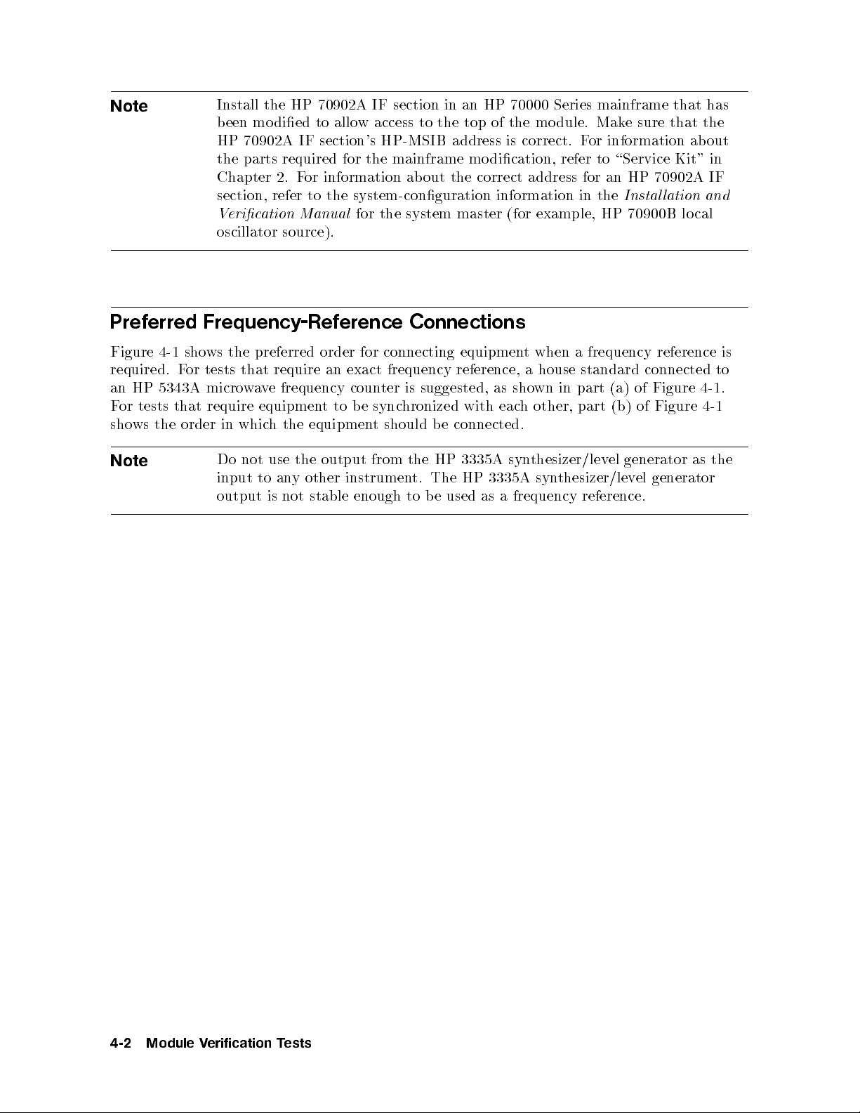
Note
Preferred Frequency-Reference Connections
Figure 4-1 shows the preferred order for connecting equipment when a frequency reference is
required. For tests that require an exact frequency reference, a house standard connected to
an HP 5343A microwave frequency counter is suggested, as shown in part (a) of Figure 4-1.
For tests that require equipment to be synchronized with each other, part (b) of Figure 4-1
shows the order in which the equipment should be connected.
Install the HP 70902A IF section in an HP 70000 Series mainframe that has
been mo died to allow access to the top of the module. Make sure that the
HP 70902A IF section's HP-MSIB address is correct. For information about
the parts required for the mainframe modication, refer to \Service Kit" in
Chapter 2. For information about the correct address for an HP 70902A IF
section, refer to the system-conguration information in the
Verication Manual
oscillator source).
for the system master (for example, HP 70900B lo cal
Installation and
Note
Do not use the output from the HP 3335A syn
input to any other instrument. The HP 3335A synthesizer/level generator
output is not stable enough to b e used as a frequency reference.
thesizer/level generator as the
4-2 Module Verification Tests
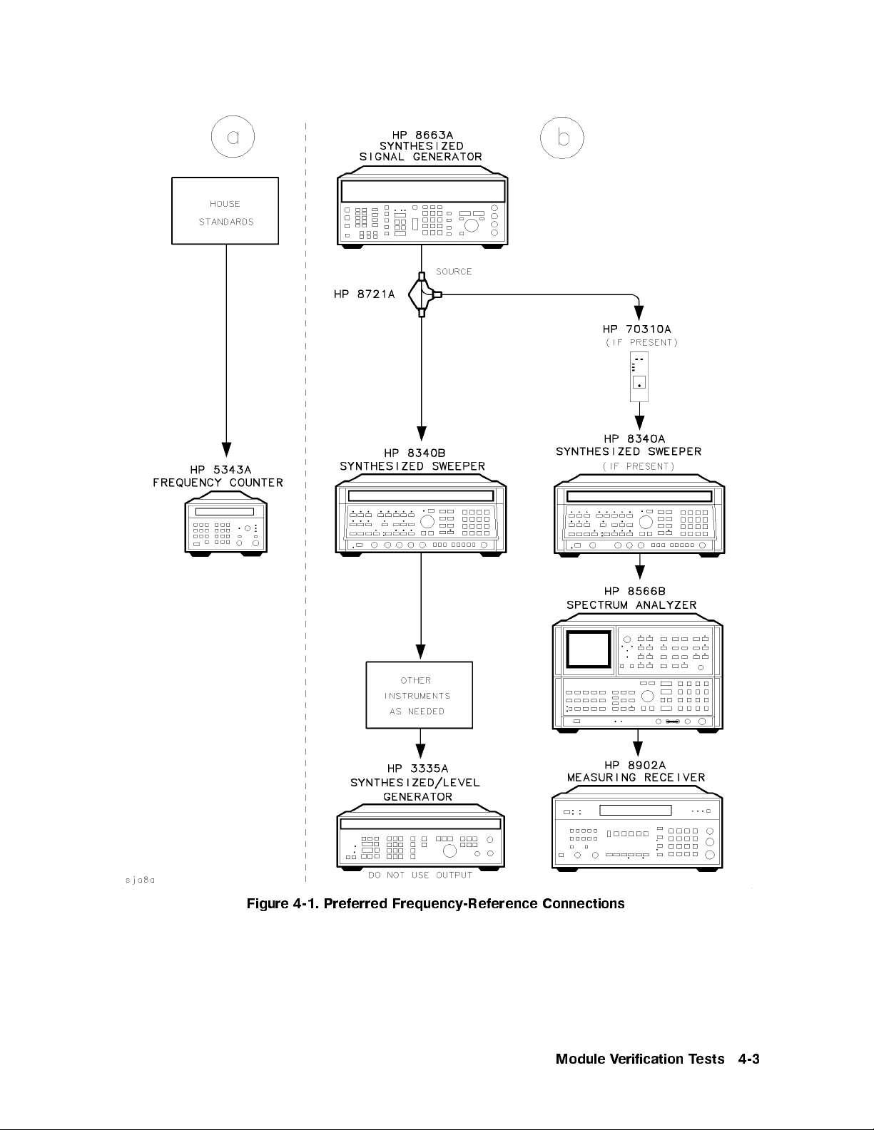
Figure 4-1. Preferred Frequency-Reference Connections
Module Verification Tests 4-3
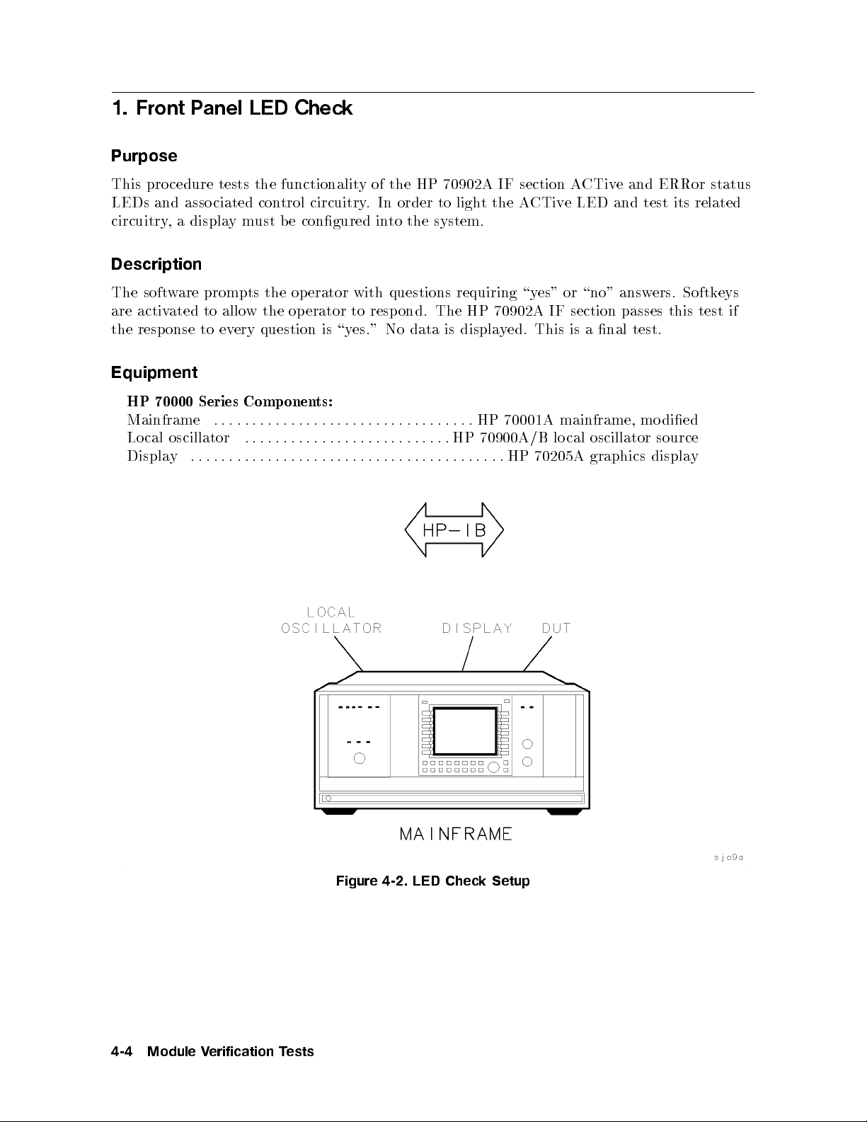
1. Front Panel LED Check
Purpose
This procedure tests the functionality of the HP 70902A IF section ACTive and ERRor status
LEDs and asso ciated control circuitry. In order to light the ACTive LED and test its related
circuitry, a displaymust be congured into the system.
Description
The software prompts the op erator with questions requiring \yes" or \no" answers. Softkeys
are activated to allow the op erator to respond. The HP 70902A IF section passes this test if
the response to every question is \yes." No data is displayed. This is a nal test.
Equipment
HP 70000 Series Components:
Mainframe .................................. HP 70001A mainframe, mo died
Local oscillator ...........................HP
Display .........................................HP
70900A/B lo cal oscillator source
70205A graphics display
4-4 Module Verification Tests
Figure 4-2. LED Check Setup
2. Diagnostic Detectors Check
2. Diagnostic Detectors Check
Purpose
This test checks that the HP 70902A IF section diagnostic detectors are functional, and
measures the signal levels at which the detectors become active. These detectors report to the
local oscillator module if an insucient signal level is present inside the HP 70902A IF section
during the system-calibration routine, or during system diagnostics testing.
There are two detectors inside the mo dule. Detector 1 detects the level of the 21.4 MHz input
signal. Detector 2 detects the video-output voltage level.
Description
The level generator is connected to the power splitter input. One power splitter output is
connected to the 21.4 MHz input of the device under test (DUT). The other p ower splitter
output is connected, through the power sensor, to the power meter. The precision DVM is
connected to the DUT video output across a 50 termination. The level generator is tuned to
the center of the selected resolution bandwidth lter. Then, with the aid of the po
wer meter,
the level generator is set to provide a power level of06 dBm to the DUT 21.4 MHz input.
The level generator is then set to provide a023 dBm signal at the 21.4 MHz input. If an
y
detector is on (active) at this level, the test rep orts an error.
The level generator output is then increased in amplitude b
is monitored for detector turn-on. When a detector turns on, the lev
value that caused the detector to turn on is stored in a v
y 1 dB steps while the HP-MSIB
el generator amplitude
ariable. If the level generator reaches
13 dBm b efore all detectors turn on, the test rep orts an error.
After all detectors turn on, the level generator is returned to 10 dB belo
turn-on level and waits for the detector to turn o. After the detector turns o, the lev
w the rst detector
el
generator is set to 1.5 dB b elow the previously measured turn-on level. Then the level
generator amplitude level is increased by 0.1 dB steps until the detector turns on again. This
amplitude level is measured by the power meter and becomes the recorded turn-on level for
that detector. This process is rep eated for each detector.
Equipment
Level generator ......................... HP 3335A synthesizer/level generator
Power meter . . . . . .
..............................HP
Power sensor ..................................... HP
Power splitter . . . . . .................................HP
Precision DVM .................................HP
8902A measuring receiver
11722A sensor mo dule
11667A power splitter
3456A digital multimeter
HP 70000 Series Components:
Mainframe ..................................HP
70001A mainframe, mo died
Local oscillator ...........................HP 70900A/B local oscillator source
Accessories
HP 1250-0676 precision 50 SMB(f ) termination
Module Verification Tests 4-5

2. Diagnostic Detectors Check
Adapters
HP 1250-0780 50 N(m) to BNC(f )
HP 1250-0671 50 SMB(m) to N(m)
HP 1250-1391 50 SMB tee(f ) (m) (m)
HP 1251-2277 50 BNC(f ) to dual banana plug
Cables
HP 10503A 122 cm (48 in) 50 coax BNC(m) to BNC(m)
HP 8120-5016 160 mm (6.3 in) SMB(f ) to SMB(f)
HP 85680-60093 123 cm (48.4 in) 50 BNC(m) to SMB(f)
Figure 4-3. Diagnostic Detectors Check Setup
4-6 Module Verification Tests

3. 18.4 MHz Oscillator Stability Test
3. 18.4 MHz Oscillator Stability Test
Purpose
This test measures the stability of the HP 70902A IF section 18.4 MHz oscillator over a
ve-minute time span.
This is not a nal test, but it should be run if a problem is susp ected, or if repairs related to
the oscillator have been made.
Description
A frequency counter is connected to the 18.4 MHz output, and samples are taken over ve
minutes. If the oscillator drifts more than65Hzinve minutes, the test fails. The results are
displayed in a graph.
Equipment
Frequency counter ................................ HP
HP 70000 Series Components:
Mainframe ..................................HP
Local oscillator ...........................HP
Adapters
HP 1250-0669 50 SMB(m) to SMB(m)
HP 1250-0672 50 SMB(f ) to SMB(f )
Cables
HP 85680-60093 123 cm (48.4 in) 50 BNC(m) to SMB(f )
70001A mainframe, mo died
70900A/B local oscillator source
5316B universal counter
Module Verification Tests 4-7

3. 18.4 MHz Oscillator Stability Test
Figure 4-4. 18.4 MHz Oscillator Stability Test Setup
4-8 Module Verification Tests

4. DUT Calibration
4. DUT Calibration
Purpose
This test simulates the routines of the HP 70000 Series system calibration that pertain to the
HP 70902A IF sections. The purpose of this test is to establish log delity, absolute gain, and
resolution bandwidth correction factors. The correction factors will be used to make corrected
measurements in the following tests:
Corrected Mo dule Fidelity
Corrected Sensitivity
Third-Order Intercept
Spurious Responses
DUT Calibration must be run before performing any of the tests listed above.
Make sure covers are secure and mo dule is warmed up for at least one hour prior to running
tests.
Description
The level generator is connected to the power splitter input. One power splitter output is
connected to the 21.4 MHz input of the device under test (DUT). The other p o
output is connected, through the power sensor, to the power meter. With the aid of the po
wer splitter
wer
meter, the level generator is set to provide a power level of05 dBm to the DUT 21.4 MHz
input. (A05 dBm input should result in 2 Vdc being presen
t at the DUT video output.
Refer to \Absolute-Gain Error Correction".) The precision DVM is connected to the DUT
video output across a 50 termination.
Log-Fidelity Error Correction
As the calibration attenuator in the DUT HP 70902A IF section is stepped from 0 dB to
0
11 dB, the DUT video-output voltage is read for each step. After the011 dB reading,
the DUT calibration attenuator is reset to 0 dB, the RF atten
uator in the level generator is
stepped down 10 dB, and the DUT video-output voltage is read again.
This reading is compared to the previous010 dB reading, and any dierence is attributed
to RF-attenuator error. An oset, calculated to correct for this error, is applied to the next
0dBto011 dB decade as the measuring sequence is continued. In this fashion, log delityis
measured down to the HP 70902A IF section noise oor.
The correction factors are stored in a COMMON array for use b
y other tests.
Absolute-Gain Error Correction
Theoretically,a05 dBm input signal applied to the DUT 21.4 MHz input should result in
2 Vdc b eing present at the DUT video output. The absolute gain error is the dierence
between the theoretical input power of05 dBm and the actual input power required to obtain
2 Vdc at the DUT video output. The correction factor is the opp osite of this error.
Module Verification Tests 4-9

4. DUT Calibration
Bandwidth-Switching Error Correction
The level generator is tuned to the center of the DUT reference bandwidth, and then the DUT
video-output voltage is measured. This is the reference voltage.
The level generator is then tuned to the center of each bandwidth, and the resulting
video-output voltage is measured. The bandwidth-switching error is the dierence between
this voltage and the reference voltage. The correction factor is the opposite of the bandwidth
switching error.
Equipment
Level generator ......................... HP 3335A synthesizer/level generator
Power meter ....................................HP 8902A measuring receiver
Power sensor ..................................... HP 11722A sensor module
Power splitter . . . . . . ................................HP 11667A power splitter
Precision DVM ................................. HP 3456A digital multimeter
HP 70000 Series Components:
Mainframe .................................. HP
Local oscillator ...........................HP
70001A mainframe, mo died
70900A/B lo cal oscillator source
Accessories
HP 1250-0676 precision 50 SMB(f ) termination
Adapters
HP 1250-0780 50 N(m) to BNC(f )
HP 1250-0671 50 SMB(m) to N(m)
HP 1250-1391 50 SMB tee(f ) (m) (m)
HP 1251-2277 50 BNC(f ) to dual banana plug
Cables
HP 10503A 122 cm (48 in) 50 coax BNC(m) to BNC(m)
HP 8120-5016 160 mm (6.3 in) SMB(f ) to SMB(f)
HP 85680-60093 123 cm (48.4 in) 50 BNC(m) to SMB(f)
4-10 Module Verification Tests

4. DUT Calibration
Figure 4-5. DUT Calibration Setup
Module Verification Tests 4-11
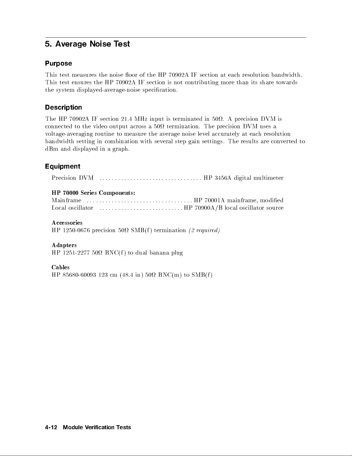
5. Average Noise Test
Purpose
This test measures the noise o or of the HP 70902A IF section at each resolution bandwidth.
This test ensures the HP 70902A IF section is not contributing more than its share towards
the system displayed-average-noise sp ecication.
Description
The HP 70902A IF section 21.4 MHz input is terminated in 50. A precision DVM is
connected to the video output across a 50 termination. The precision DVM uses a
voltage-averaging routine to measure the average noise level accurately at each resolution
bandwidth setting in combination with several step gain settings. The results are converted to
dBm and displayed in a graph.
Equipment
Precision DVM ................................. HP
HP 70000 Series Components:
Mainframe .................................. HP
Local oscillator ...........................HP
Accessories
HP 1250-0676 precision 50 SMB(f ) termination
Adapters
HP 1251-2277 50 BNC(f ) to dual banana plug
Cables
HP 85680-60093 123 cm (48.4 in) 50 BNC(m) to SMB(f)
70001A mainframe, mo died
70900A/B lo cal oscillator source
(2 required)
3456A digital multimeter
4-12 Module Verification Tests
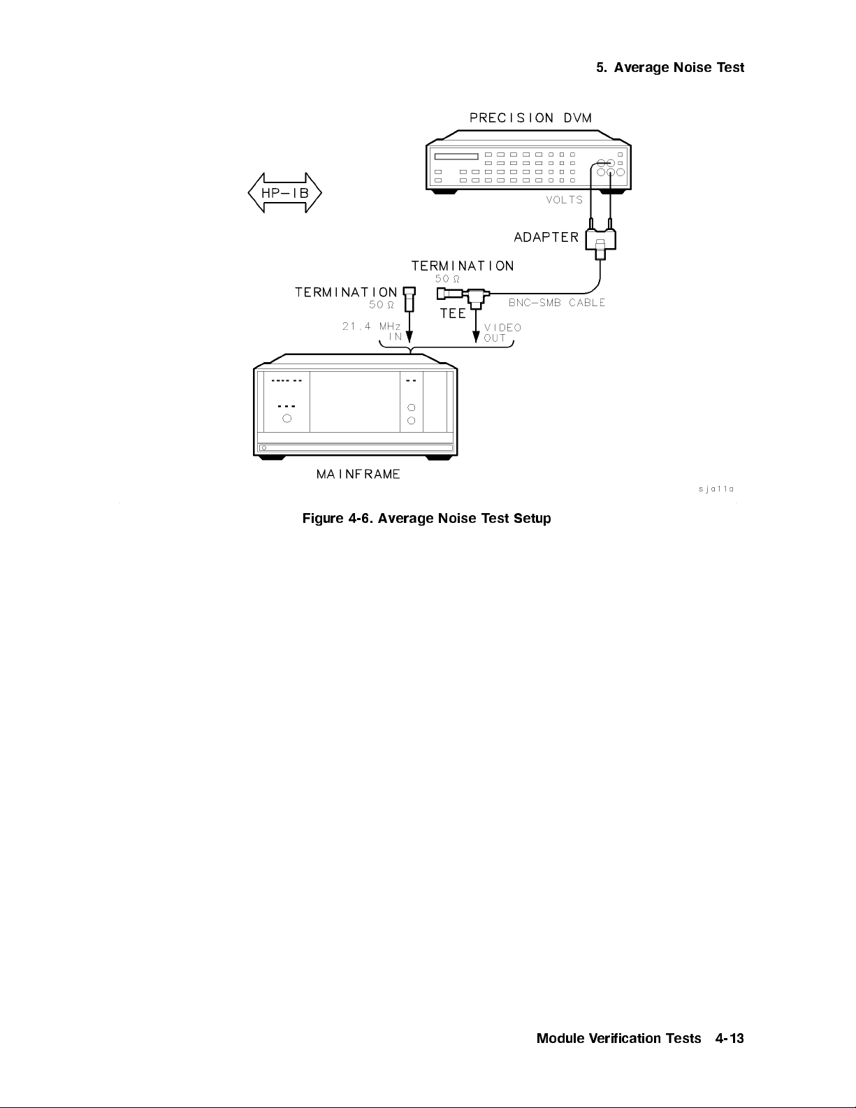
5. Average Noise Test
Figure 4-6. Average Noise Test Setup
Module Verification Tests 4-13
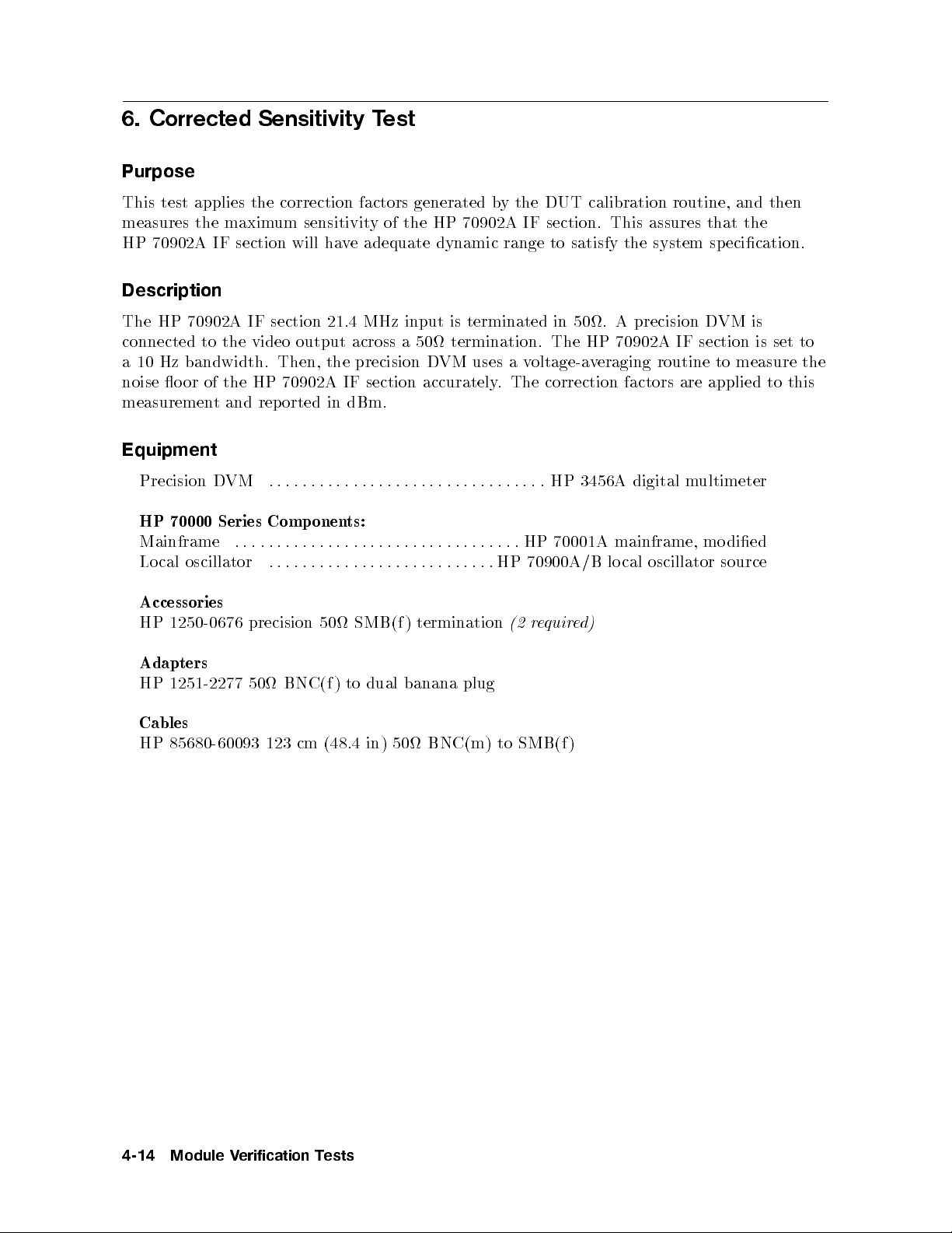
6. Corrected Sensitivity Test
Purpose
This test applies the correction factors generated by the DUT calibration routine, and then
measures the maximum sensitivity of the HP 70902A IF section. This assures that the
HP 70902A IF section will have adequate dynamic range to satisfy the system specication.
Description
The HP 70902A IF section 21.4 MHz input is terminated in 50. A precision DVM is
connected to the video output across a 50 termination. The HP 70902A IF section is set to
a 10 Hz bandwidth. Then, the precision DVM uses a voltage-averaging routine to measure the
noise oor of the HP 70902A IF section accurately. The correction factors are applied to this
measurement and reported in dBm.
Equipment
Precision DVM ................................. HP
HP 70000 Series Components:
Mainframe .................................. HP
Local oscillator ...........................HP
Accessories
HP 1250-0676 precision 50 SMB(f ) termination
Adapters
HP 1251-2277 50 BNC(f ) to dual banana plug
Cables
HP 85680-60093 123 cm (48.4 in) 50 BNC(m) to SMB(f)
70001A mainframe, mo died
70900A/B lo cal oscillator source
(2 required)
3456A digital multimeter
4-14 Module Verification Tests
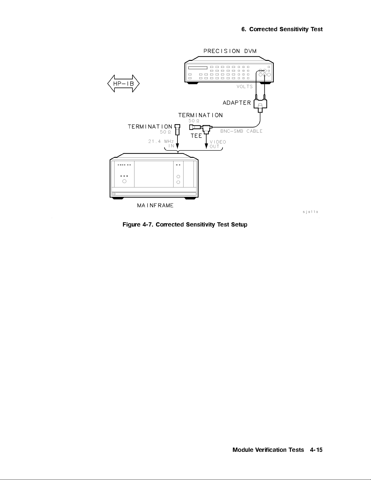
6. Corrected Sensitivity Test
Figure 4-7. Corrected Sensitivity Test Setup
Module Verification Tests 4-15
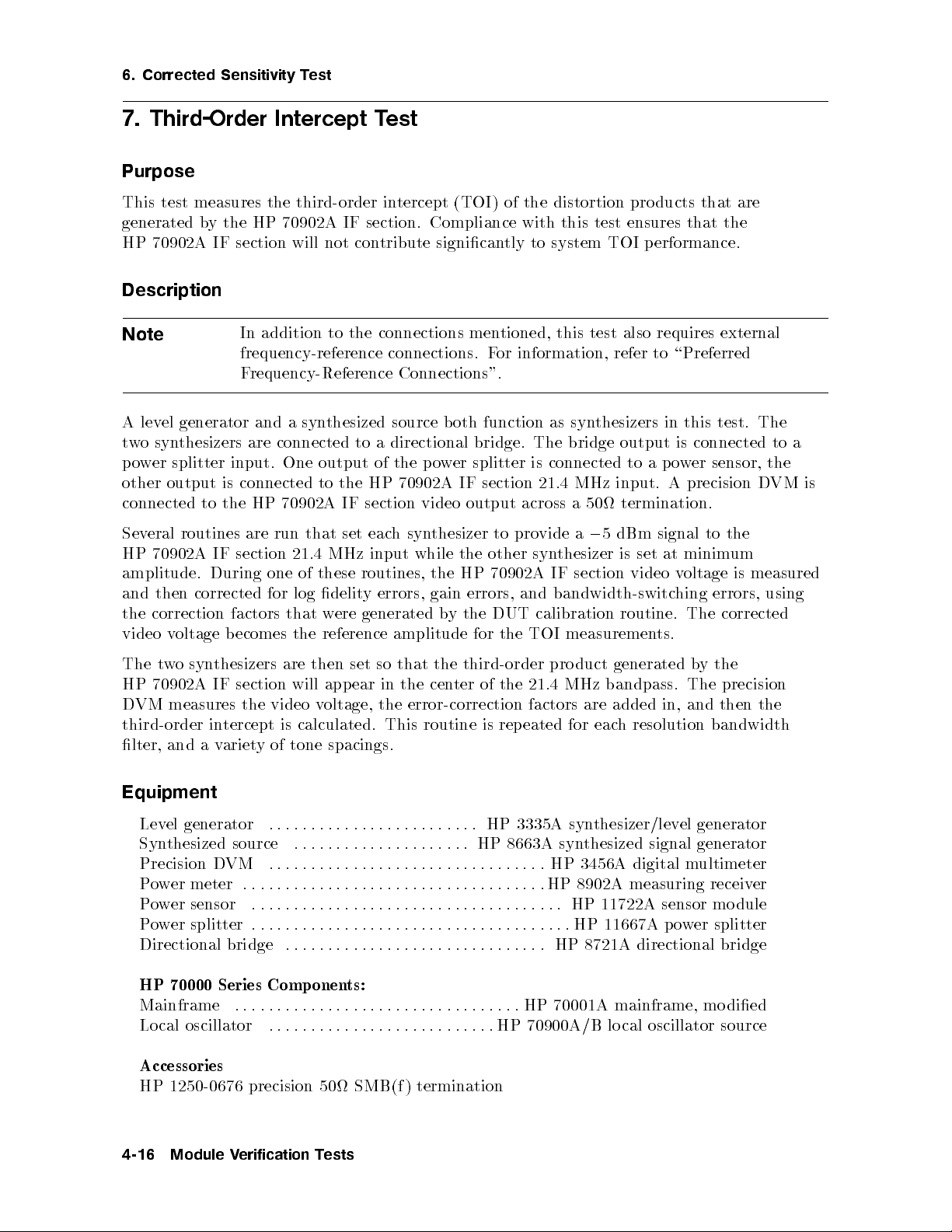
6. Corrected Sensitivity Test
7. Third-Order Intercept Test
Purpose
This test measures the third-order intercept (TOI) of the distortion pro ducts that are
generated by the HP 70902A IF section. Compliance with this test ensures that the
HP 70902A IF section will not contribute signicantly to system TOI performance.
Description
Note
In addition to the connections mentioned, this test also requires external
frequency-reference connections. For information, refer to \Preferred
Frequency-Reference Connections".
A level generator and a synthesized source both function as synthesizers in this test. The
two synthesizers are connected to a directional bridge. The bridge output is connected to a
power splitter input. One output of the po
wer splitter is connected to a po
other output is connected to the HP 70902A IF section 21.4 MHz input. A precision D
wer sensor, the
VM is
connected to the HP 70902A IF section video output across a 50 termination.
Several routines are run that set each synthesizer to provide a05 dBm signal to the
HP 70902A IF section 21.4 MHz input while the other syn
amplitude. During one of these routines, the HP 70902A IF section video v
thesizer is set at minimum
oltage is measured
and then corrected for log delity errors, gain errors, and bandwidth-switching errors, using
the correction factors that were generated by the DUT calibration routine. The corrected
video voltage becomes the reference amplitude for the TOI measuremen
The two synthesizers are then set so that the third-order product generated b
HP 70902A IF section will appear in the cen
ter of the 21.4 MHz bandpass. The precision
ts.
y the
DVM measures the video voltage, the error-correction factors are added in, and then the
third-order intercept is calculated. This routine is rep eated for eac
h resolution bandwidth
lter, and a variety of tone spacings.
Equipment
Level generator ......................... HP 3335A synthesizer/level generator
Synthesized source ..................... HP
Precision DVM ................................. HP
Power meter ....................................HP
Power sensor ..................................... HP
Power splitter . . . . . . ................................HP
Directional bridge ............................... HP
8663A synthesized signal generator
3456A digital multimeter
8902A measuring receiver
11722A sensor mo dule
11667A power splitter
8721A directional bridge
HP 70000 Series Components:
Mainframe .................................. HP 70001A mainframe, mo died
Local oscillator ...........................HP 70900A/B lo cal oscillator source
Accessories
HP 1250-0676 precision 50 SMB(f ) termination
4-16 Module Verification Tests
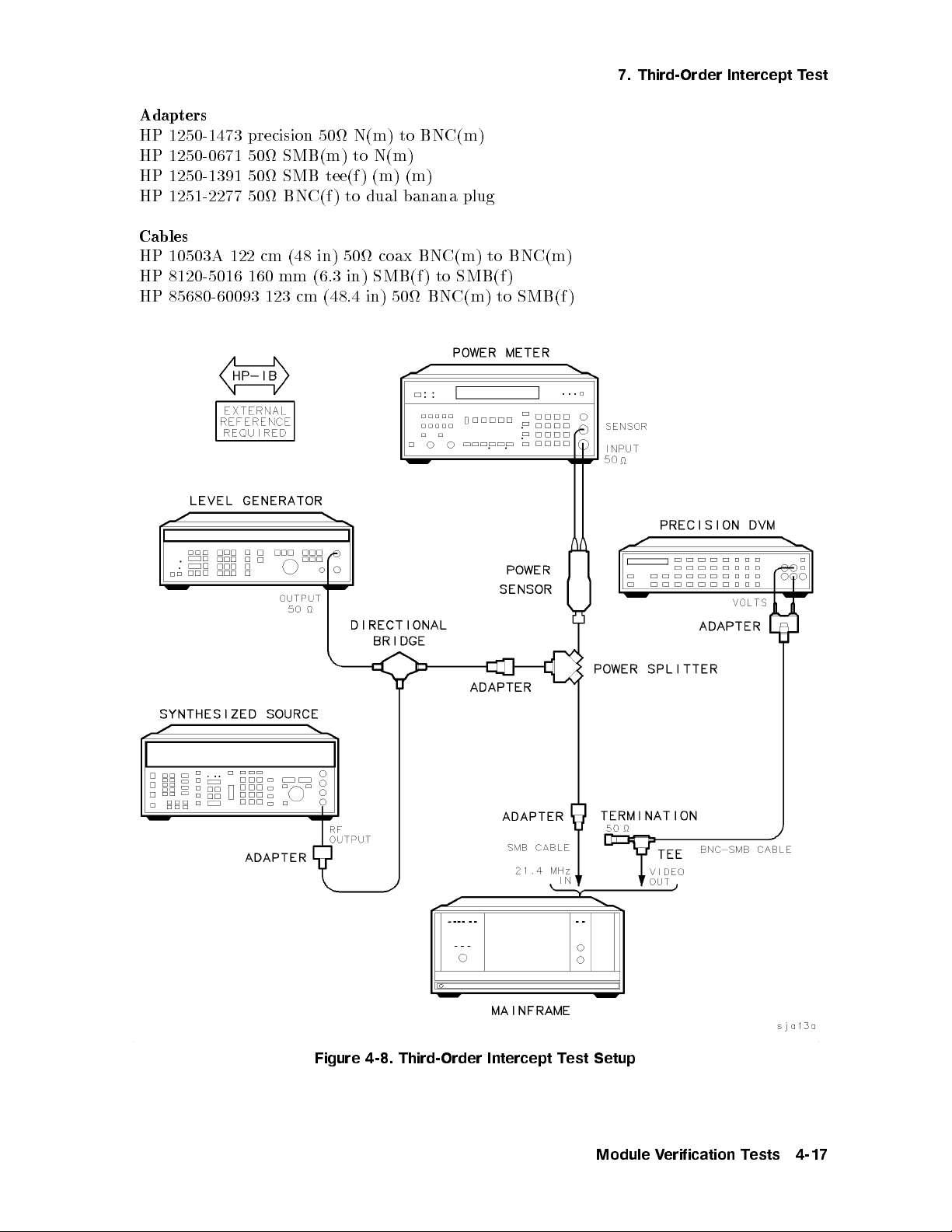
Adapters
HP 1250-1473 precision 50 N(m) to BNC(m)
HP 1250-0671 50 SMB(m) to N(m)
HP 1250-1391 50 SMB tee(f ) (m) (m)
HP 1251-2277 50 BNC(f ) to dual banana plug
Cables
HP 10503A 122 cm (48 in) 50 coax BNC(m) to BNC(m)
HP 8120-5016 160 mm (6.3 in) SMB(f ) to SMB(f )
HP 85680-60093 123 cm (48.4 in) 50 BNC(m) to SMB(f )
7. Third-Order Intercept Test
Figure 4-8. Third-Order Intercept Test Setup
Module Verification Tests 4-17
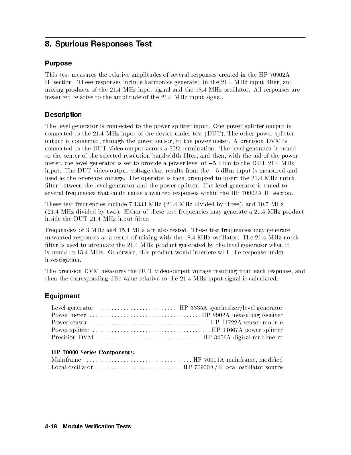
8. Spurious Responses Test
Purpose
This test measures the relative amplitudes of several responses created in the HP 70902A
IF section. These responses include harmonics generated in the 21.4 MHz input lter, and
mixing products of the 21.4 MHz input signal and the 18.4 MHz oscillator. All responses are
measured relative to the amplitude of the 21.4 MHz input signal.
Description
The level generator is connected to the power splitter input. One power splitter output is
connected to the 21.4 MHz input of the device under test (DUT). The other power splitter
output is connected, through the power sensor, to the power meter. A precision DVM is
connected to the DUT video output across a 50 termination. The level generator is tuned
to the center of the selected resolution bandwidth lter, and then, with the aid of the power
meter, the level generator is set to provide a power level of05 dBm to the DUT 21.4 MHz
0
input. The DUT video-output v
oltage that results from the
used as the reference voltage. The operator is then prompted to insert the 21.4 MHz notc
5 dBm input is measured and
h
lter between the level generator and the power splitter. The level generator is tuned to
several frequencies that could cause unwanted responses within the HP 70902A IF section.
These test frequencies include 7.1333 MHz (21.4 MHz divided b
y three), and 10.7 MHz
(21.4 MHz divided bytwo). Either of these test frequencies may generate a 21.4 MHz product
inside the DUT 21.4 MHz input lter.
Frequencies of 3 MHz and 15.4 MHz are also tested. These test frequencies ma
unwanted responses as a result of mixing with the 18.4 MHz oscillator. The 21.4 MHz notc
y generate
h
lter is used to attenuate the 21.4 MHz product generated by the level generator when it
is tuned to 15.4 MHz. Otherwise, this product w
ould interfere with the response under
investigation.
The precision DVM measures the DUT video-output voltage resulting from each resp onse, and
then the corresp onding dBc value relativ e to the 21.4 MHz input signal is calculated.
Equipment
Level generator ......................... HP 3335A synthesizer/level generator
Power meter ....................................HP
Power sensor ..................................... HP
Power splitter . . . . . . ................................HP
Precision DVM ................................. HP
8902A measuring receiver
11722A sensor mo dule
11667A power splitter
3456A digital multimeter
HP 70000 Series Components:
Mainframe .................................. HP
70001A mainframe, mo died
Local oscillator ...........................HP 70900A/B lo cal oscillator source
4-18 Module Verification Tests
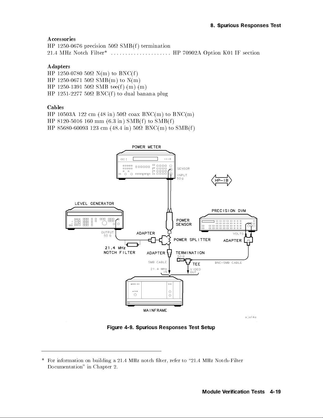
8. Spurious Responses Test
Accessories
HP 1250-0676 precision 50 SMB(f ) termination
21.4 MHz Notch Filter* ..................... HP 70902A Option K01 IF section
Adapters
HP 1250-0780 50 N(m) to BNC(f )
HP 1250-0671 50 SMB(m) to N(m)
HP 1250-1391 50 SMB tee(f ) (m) (m)
HP 1251-2277 50 BNC(f ) to dual banana plug
Cables
HP 10503A 122 cm (48 in) 50 coax BNC(m) to BNC(m)
HP 8120-5016 160 mm (6.3 in) SMB(f ) to SMB(f )
HP 85680-60093 123 cm (48.4 in) 50 BNC(m) to SMB(f )
Figure 4-9. Spurious Responses Test Setup
*For information on building a 21.4 MHz notc
Documentation" in Chapter 2.
h lter, refer to \21.4 MHz Notc
Module Verification Tests 4-19
h-Filter
9. Resolution Bandwidths Test
Purpose
This test measures the 3 dB bandwidth, center frequency, amplitude shift, and shape factor
(60 dB/3 dB ratio) of each HP 70902A IF section bandwidth lter. It tests only the 1 and 3
sequence of lters, not the 10 percent increments between lter stages.
Description
The level generator is connected to the power splitter input. One power splitter output is
connected to the 21.4 MHz input of the device under test (DUT). The other power splitter
output is connected, through the power sensor, to the power meter. The level generator is
tuned to the center of the selected resolution bandwidth lter. Then, with the aid of the
power meter, the level generator is set to provide a p ower level of05 dBm to the DUT
21.4 MHz input. The precision DVM is connected to the DUT video output across a 50
termination.
The synthesized source is connected, through a cable and adapter, to the 18.4 MHz oscillator
test point (A1J103). The frequency counter is connected to the limited IF output on the DUT
rear panel. The frequency counter measures the output signal, and the actual frequency of the
DUT 18.4 MHz oscillator is calculated.
The synthesized source is set to the calculated frequency at 8 dBm to \injection-lo c
k" the
18.4 MHz oscillator. This prevents drift in this oscillator from adding measurement error for
the duration of the test.
First, the reference bandwidth ( 100 Hz) is measured for center frequency, 3 dB bandwidth,
amplitude, and shap e factor. Then each of the other bandwidths is measured for cen
ter
frequency, 3 dB bandwidth, and shap e factor. Bandwidth amplitude-switching error is
measured relative to the reference bandwidth.
Equipment
Synthesized source ..................... HP 8663A synthesized signal generator
Frequency counter ................................ HP 5316A universal counter
Level generator ......................... HP 3335A synthesizer/level generator
Power meter ....................................HP 8902A measuring receiver
Power sensor ..................................... HP
Power splitter . . . . . . ................................HP
Precision DVM ................................. HP
11722A sensor mo dule
11667A power splitter
3456A digital multimeter
HP 70000 Series Components:
Mainframe .................................. HP
Local oscillator ...........................HP
70001A mainframe, mo died
70900A/B lo cal oscillator source
Accessories
HP 1250-0676 precision 50 SMB(f ) termination
4-20 Module Verification Tests
Adapters
HP 1250-0780 50 N(m) to BNC(f )
HP 1250-1476 precision 50 N(m) to BNC(f )
HP 1250-0671 50 SMB(m) to N(m)
HP 1250-1391 50 SMB tee(f ) (m) (m)
HP 1251-2277 50 BNC(f ) to dual banana plug
Cables
HP 10503A 122 cm (48 in) 50 coax BNC(m) to BNC(m)
HP 8120-5016 160 mm (6.3 in) SMB(f ) to SMB(f )
HP 85680-60093 123 cm (48.4 in) 50 BNC(m) to SMB(f )
9. Resolution Bandwidths Test
Module Verification Tests 4-21

9. Resolution Bandwidths Test
Figure 4-10. Resolution Bandwidths Test Setup
4-22 Module Verification Tests
10. Video Bandwidths Test
10. Video Bandwidths Test
Purpose
This test measures the dc error of the HP 70902A IF section video lters. The dc error
is dened as the shift in DUT video-output voltage measured as each video bandwidth is
selected. The shift is measured relative to the DUT video-output voltage present at the
reference video bandwidth (300 kHz).
Description
The level generator is connected to the power splitter input. One power splitter output is
connected to the 21.4 MHz input of the device under test (DUT). The other p ower splitter
output is connected, through the power sensor, to the power meter. The precision DVM is
connected to the DUT video output across a 50 termination. With the aid of the power
meter, the level generator is set to provide a power level of05 dBm to the DUT 21.4 MHz
input.
To measure the reference voltage, the level generator is set to provide 2 Vdc at the DUT video
output. To measure the dc error, each video bandwidth is selected and the DUT video-output
voltage for that bandwidth is measured. The dierences bet
ween these voltages and the
reference bandwidth voltage are reported as dc error.
Equipment
Level generator ......................... HP
Power meter . . . . . . ..............................HP
Power sensor ..................................... HP
Power splitter . . . . . .................................HP
Precision DVM .................................HP
3335A synthesizer/level generator
8902A measuring receiver
11722A sensor mo dule
11667A power splitter
3456A digital multimeter
HP 70000 Series Components:
Mainframe ..................................HP 70001A mainframe, mo died
Local oscillator ...........................HP 70900A/B local oscillator source
Accessories
HP 1250-0676 precision 50 SMB(f ) termination
Adapters
HP 1250-0780 50 N(m) to BNC(f )
HP 1250-0671 50 SMB(m) to N(m)
HP 1250-1391 50 SMB tee(f ) (m) (m)
HP 1251-2277 50 BNC(f ) to dual banana plug
Module Verification Tests 4-23

10. Video Bandwidths Test
Cables
HP 10503A 122 cm (48 in) 50 coax BNC(m) to BNC(m)
HP 8120-5016 160 mm (6.3 in) SMB(f ) to SMB(f)
HP 85680-60093 123 cm (48.4 in) 50 BNC(m) to SMB(f)
Figure 4-11. Video Bandwidths Test Setup
4-24 Module Verification Tests

11. Module Gain Test
11. Module Gain Test
Purpose
This test measures the dierence between05 dBm and the level of 21.4 MHz input signal
required to pro duce exactly 2 Vdc at the HP 70902A IF section video-output p ort.
Description
The level generator is connected to the power splitter input. One power splitter output is
connected to the 21.4 MHz input of the device under test (DUT). The other p ower splitter
output is connected, through the power sensor, to the power meter. The precision DVM is
connected to the DUT video output across a 50 termination.
The level generator is tuned to the center of the selected resolution bandwidth lter. The
level generator amplitude is adjusted to provide exactly 2 Vdc (as measured by the DVM) at
the DUT video output. The power meter takes a number of samples and averages them to
determine the signal level at the 21.4 MHz input accurately. This averaged value is compared
to05 dBm, and the dierence is reported.
Equipment
Level generator ......................... HP
Power meter . . . . . . ..............................HP
3335A synthesizer/level generator
8902A measuring receiver
Power sensor ..................................... HP
Power splitter . . . . . .................................HP
Precision DVM .................................HP
3456A digital multimeter
HP 70000 Series Components:
Mainframe ..................................HP
Local oscillator ...........................HP
70001A mainframe, mo died
70900A/B local oscillator source
Accessories
HP 1250-0676 precision 50 SMB(f ) termination
Adapters
HP 1250-0780 50 N(m) to BNC(f )
HP 1250-0671 50 SMB(m) to N(m)
HP 1250-1391 50 SMB tee(f ) (m) (m)
HP 1251-2277 50 BNC(f ) to dual banana plug
11722A sensor mo dule
11667A power splitter
Module Verification Tests 4-25

11. Module Gain Test
Cables
HP 10503A 122 cm (48 in) 50 coax BNC(m) to BNC(m)
HP 8120-5016 160 mm (6.3 in) SMB(f ) to SMB(f)
HP 85680-60093 123 cm (48.4 in) 50 BNC(m) to SMB(f)
Figure 4-12. Module Gain Test Setup
4-26 Module Verification Tests

12. Calibration Attenuator Test
12. Calibration Attenuator Test
Purpose
This test veries the accuracy of the HP 70902A IF section calibration attenuator. This
accuracy is critical to achieving specied system performance. The calibration attenuator is
used by the system to calibrate system log delity during the system-calibration routine. It is
also used by the system to adjust the HP 70902A IF section gain in some combinations of step
gain, bandwidth, and reference level.
Description
The calibration attenuator is a precise PIN-diode attenuator circuit consisting of 1 dB, 2 dB,
4dB,8dB, and 30 dB stages. It may be set from 0 dB to 15 dB, and 30 dB to 45 dB with
1 dB resolution. Atambient room temperature, the calibration attenuator 1 dB,2dB, 4 dB,
and 8 dB stages are specied to60.03 dB, and the 30 dB stage is sp ecied to60.05 dB.
The level generator is connected to the power splitter input. One power splitter output is
connected to the 21.4 MHz input of the device under test (DUT). The other p o
output is connected, through the signal sensor, to the measuring receiv
er. A precision DVM is
wer splitter
connected to the DUT video output across a 50 termination. The TUNED RF calibration of
the measuring receiver is rst checked, and then p erformed if necessary.
The level generator is set to provide016 dBm at the DUT 21.4 MHz input, and the DUT
video-output voltage is measured and used as the reference v
oltage. With the aid of the
measuring receiver, the level generator output is reduced in amplitude by exactly the value
of the calibration-attenuator step being measured. Then, the DUT video-output v
is measured. Next, the level generator is reset to the original amplitude of
0
oltage
16 dBm, the
calibration-attenuator step is activated, and the video voltage is again measured. The error
between this measurement and the previous voltage measurement is the attenuator error. This
measuring sequence is repeated for each stage of the calibration attenuator.
Equipment
Level generator ......................... HP 3335A synthesizer/level generator
Measuring receiver ..............................HP 8902A measuring receiver
Signal sensor ..................................... HP 11722A sensor mo dule
Power splitter . . . . . .................................HP 11667A power splitter
Precision DVM .................................HP
3456A digital multimeter
HP 70000 Series Components:
Mainframe ..................................HP
Local oscillator ...........................HP
70001A mainframe, mo died
70900A/B local oscillator source
Accessories
HP 1250-0676 precision 50 SMB(f ) termination
Module Verification Tests 4-27
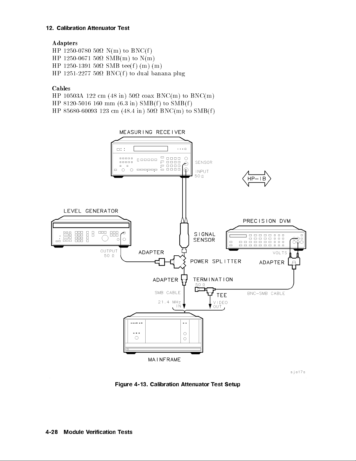
12. Calibration Attenuator Test
Adapters
HP 1250-0780 50 N(m) to BNC(f )
HP 1250-0671 50 SMB(m) to N(m)
HP 1250-1391 50 SMB tee(f ) (m) (m)
HP 1251-2277 50 BNC(f ) to dual banana plug
Cables
HP 10503A 122 cm (48 in) 50 coax BNC(m) to BNC(m)
HP 8120-5016 160 mm (6.3 in) SMB(f ) to SMB(f)
HP 85680-60093 123 cm (48.4 in) 50 BNC(m) to SMB(f)
Figure 4-13. Calibration Attenuator Test Setup
4-28 Module Verification Tests
13. Corrected Module Fidelity Test
13. Corrected Module Fidelity Test
Purpose
This test measures the corrected delity of the HP 70902A IF section. Corrected delity
consists of the combinations of log delity performance, step gain accuracy, and sensitivity
at various resolution bandwidths. This delity is essential for achieving sp ecied system
performance.
Description
The level generator is connected, through a 10 dB step attenuator, to the power splitter input.
(The 10 dB step attenuator is used to increase the dynamic range of the level generator to
cover the range of05 dBm to01.5 dBm.)
Note
Because this test take approximately 20 minutes, a programmable 10 dB step
attenuator and accompanying attenuator driver are recommended. If these are
not available, a manual 10 dB step atten
uator may be used.
One power splitter output is connected to the 21.4 MHz input of the device under test (DUT).
The other p ower splitter output is connected, through the signal sensor, to the measuring
receiver. This provides highly accurate RF level measurements at 21.4 MHz, and is used
to establish reference amplitudes and calibrate the step atten
connected to the DUT video output across a 50 termination. The D
uator. The precision DVM is
VM is used to measure
the detected video-output voltage of the HP 70902A IF section accurately.A05 dBm input
results in approximately 2 Vdc being present at the DUT video output.
The level generator is tuned to the center of the chosen resolution bandwidth lter. The
desired step gain is programmed. The generator and step atten
uator are switched to
maximum attenuation to allow the precision DVM to sample the video output and determine
the noise o or. The step attenuator is set to the same value as the chosen step gain. The
generator is then stepped from 10 dB ab o
ve the reference level (at 2 Vdc) to the noise
oor. At high levels, one voltage reading is taken. As the noise o or is approached, a
voltage-averaging routine is used to remove the noise component statistically from the video
signal. (Fidelity measurements are not made within 10 dB of the noise o or, since the
uncertainties of these measurements render the data meaningless.)
Several combinations of resolution bandwidth and step gain are tested.
Module Verification Tests 4-29
13. Corrected Module Fidelity Test
Equipment
Level generator ......................... HP 3335A synthesizer/level generator
Measuring receiver ..............................HP 8902A measuring receiver
Signal sensor ..................................... HP 11722A sensor module
Power splitter . . . . . . ................................HP 11667A power splitter
Precision DVM ................................. HP 3456A digital multimeter
10 dB Step attenuator ............ HP 8496G Option 001 coaxial step attenuator
Attenuator driver ........................ HP 11713A attenuator/switch driver
HP 70000 Series Components:
Mainframe .................................. HP 70001A mainframe, mo died
Local oscillator ...........................HP 70900A/B lo cal oscillator source
Accessories
HP 1250-0676 precision 50 SMB(f ) termination
Adapters
HP 1250-0780 50 N(m) to BNC(f )
HP 1250-1476 precision 50 N(m) to BNC(f )
HP 1250-0671 50 SMB(m) to N(m)
HP 1250-1391 50 SMB tee(f ) (m) (m)
HP 1251-2277 50 BNC(f ) to dual banana plug
(3 required)
Cables
HP 10503A 122 cm (48 in) 50 coax BNC(m) to BNC(m)
HP 8120-5016 160 mm (6.3 in) SMB(f ) to SMB(f)
HP 85680-60093 123 cm (48.4 in) 50 BNC(m) to SMB(f)
4-30 Module Verification Tests
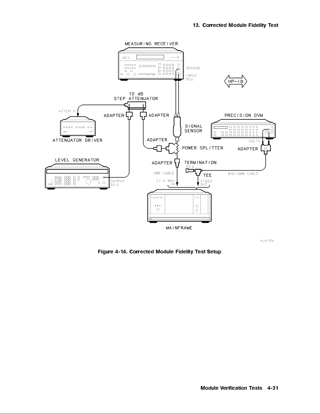
13. Corrected Module Fidelity Test
Figure 4-14. Corrected Module Fidelity Test Setup
Module Verification Tests 4-31
14. Crystal Spurs Test
Purpose
This test looks for spurious responses caused by parasitic oscillations of the resolution
bandwidth lter crystals. The spurious responses occur on the skirts of displayed signals, or,
in cases of very narrow resolution bandwidths, adjacent to displayed signals.
Description
The HP 70902A IF section is congured into an HP 70000 Series mo dular sp ectrum analyzer
system system. The system-calibration routine is performed. Then the HP 70902A IF section
is tested for crystal spurs. If any spurs are found, they are reported.
Equipment
HP 70000 Series Components:
Mainframe ...........................................HP 70001A mainframe
Local oscillator ...........................HP
Display .........................................HP
IF section ............................................ HP
RF section .......................................... HP
70900A/B lo cal oscillator source
70205A graphics display
70903A IF section
70904A RF section
Note
In addition to the cables listed b elow, additional cables will be needed to
congure the HP 70902A IF section under test into an HP 70000 Series
modular spectrum analyzer system. Refer to the
Analyzer Installation and Verication Manual
required cables.
Adapters
HP 1250-0780 50 N(m) to BNC(f )
Cables
HP 10503A 122 cm (48 in) 50 coax BNC(m) to BNC(m)
HP 70000 Modular Spectrum
for more information about the
4-32 Module Verification Tests
 Loading...