


Service Guide
HP 70900B
Local Oscillator Source
ABCDE
HP Part No. 70900-90293
Printed in USA June 1995
Edition A.0.0

Notice
The information contained in this document is subject to change without notice.
Hewlett-Packard makes no warranty of any kind with regard to this material, including,
but not limited to, the implied warranties of merchantability and tness for a particular
purpose. Hewlett-Packard shall not be liable for errors contained herein or for incidental or
consequential damages in connection with the furnishing, performance, or use of this material.
Restricted Rights Legend.
Use, duplication, or disclosure by the U.S. Government is subject to restrictions as set forth
in subparagraph (c) (1) (ii) of the Rights in Technical Data and Computer Software clause at
DFARS 252.227-7013 for DOD agencies, and subparagraphs (c) (1) and (c) (2) of the Commercial
Computer Software Restricted Rights clause at FAR 52.227-19 for other agencies.
c
Copyright Hewlett-Packard Company 1989, 1990, 1995
All Rights Reserved. Reproduction, adaptation, or translation without prior written permission
is prohibited, except as allowed under the copyright laws
1400 Fountaingrove Parkway, Santa Rosa, CA 95403-1799, USA
.

Certication
Hewlett-Packard Company certies that this product met its published specications at the
time of shipment from the factory. Hewlett-Packard further certies that its calibration
measurements are traceable to the United States National Institute of Standards and
Technology, to the extent allowed by the Institute's calibration facility, and to the calibration
facilities of other International Standards Organization members.
Warranty
This Hewlett-Packard instrument product is warranted against defects in material and
workmanship for a period of one year from date of shipment. During the warranty period,
Hewlett-Packard Company will, at its option, either repair or replace products which prove to
be defective.
For warranty service or repair, this product must be returned to a service facility designated by
Hewlett-Packard. Buyer shall prepay shipping charges to Hewlett-Packard and Hewlett-Packard
shall pay shipping charges to return the product to Buyer. However, Buyer shall pay all
shipping charges, duties, and taxes for products returned to Hewlett-Packard from another
country.
Hewlett-Packard warrants that its software and rmware designated by Hewlett-P
ackard for
use with an instrument will execute its programming instructions when properly installed on
that instrument. Hewlett-Packard does not warrant that the operation of the instrument, or
software, or rmware will be uninterrupted or error-free.
Limitation of Warranty
The foregoing warranty shall not apply to defects resulting from improper or inadequate
maintenance by Buyer, Buyer-supplied software or interfacing, unauthorized modication or
misuse, operation outside of the environmental specications for the product, or improper
site preparation or maintenance.
NO OTHER WARRANTY IS EXPRESSED OR IMPLIED. HEWLETT-PACKARD SPECIFICALLY
DISCLAIMS THE IMPLIED WARRANTIES OF MERCHANTABILITY AND FITNESS FOR A
PARTICULAR PURPOSE.
Exclusive Remedies
THE REMEDIES PROVIDED HEREIN ARE BUYER'S SOLE AND EXCLUSIVE REMEDIES.
HEWLETT-PACKARD SHALL NOT BE LIABLE FOR ANY DIRECT, INDIRECT, SPECIAL,
INCIDENTAL, OR CONSEQUENTIAL DAMAGES, WHETHER BASED ON CONTRACT, TORT,
OR ANY OTHER LEGAL THEORY.
Assistance
Product maintenance agreements and other customer assistance agreements are available for
Hewlett-Packard products.
For any assistance, contact your nearest Hewlett-Packard Sales and Service Oce.
iii

Safety Symbols
The following safety symbols are used throughout this manual. Familiarize yourself with each
of the symbols and its meaning before operating this instrument.
The
CAUTION
WARNING
DANGER
CAUTION
not correctly performed or adhered to, could result in damage to or destruction
of the product or the user's work. Do not proceed beyond a
until the indicated conditions are fully understood and met.
The
WARNING
which, if not correctly performed or adhered to, could result in injury
to the user. Do not proceed beyond a
conditions are fully understood and met.
The
DANGER
reader of a procedure which, if not correctly performed or adhered to,
could result in injury or loss of life. Do not proceed beyond a
sign until the indicated conditions are fully understood and met.
sign denotes a hazard. It calls attention to a procedure which, if
CAUTION
sign denotes a hazard. It calls attention to a procedure
WARNING
sign denotes an imminent hazard to people. It warns the
sign until the indicated
sign
DANGER
iv

General Safety Considerations
WARNING
WARNING
The instructions in this document are for use by qualied personnel
only.To avoid electrical shock, do not perform any servicing unless you
are qualied to do so.
The opening of covers or removal of parts is likely to expose dangerous
voltages. Disconnect the instrument from all voltage sources while it is
being opened.
The power cord is connected to internal capacitors that may remain live
for ve seconds after disconnecting the plug from its power supply.
This is a Safety Class 1 Product (provided with a protective earthing
ground incorporated in the power cord). The mains plug shall only be
inserted in a socket outlet provided with a protective earth contact.
Any interruption of the protective conductor inside or outside of the
instrument is likely to make the instrument dangerous. Intentional
interruption is prohibited.
For continued protection against re hazard, replace fuse only with
same type and ratings, (type nA/nV). The use of other fuses or materials
is prohibited.
Before this instrument is switched on, make sure it has been properly
grounded through the protective conductor of the ac power cable to a
socket outlet provided with protective earth contact.
Any interruption of the protective (grounding) conductor, inside
or outside the instrument, or disconnection of the protective earth
terminal can result in personal injury.
Before this instrument is switched on, make sure its primary power
circuitry has been adapted to the voltage of the ac power source
.
Failure to set the ac power input to the correct voltage could cause
damage to the instrument when the ac power cable is plugged in.
v

Servicing at a Glance
vi

The local oscillator source is a module that is used in HP 70000 Series modular measurement
systems. A standard modular spectrum analyzer system includes a mainframe with an
RF section, IF section, local oscillator, an optional display, and an optional precision frequency
reference.
Software and documentation supplied
which includes:
HP 70900B Service Guide
HP 70900B Component Level Information Packages
Module verication software disks.
Tools needed
may be needed during servicing.
Antistatic precautions
electricity. If possible, work at a static-safe work station. For further information, refer to
\Preparing a Static-Safe Work Station" in Chapter 4.
Before servicing, refer to Chapter 5 for a list of the tools and accessories that
Electrical components are easily damaged by small amounts of static
This service guide is part of an Option OB3 package
vii

In This Book
This book describes all of the service procedures necessary to test, adjust, calibrate,
troubleshoot, and repair your local oscillator source in an HP 70000 Series modular
measurement system.
Each module in the HP 70000 Series modular measurement system has its own service guide.
For further information related to the servicing of additional and alternate modules that can be
used in this system, refer to that module's service guide.
This service guide is part of an Option OB3 package which consists of two manuals.
Manual 1
Chapter 1 provides information to help get you started so that your local oscillator source is
serviced properly.
Chapter 2 contains information needed to use module verication software while servicing
your local oscillator source.
Chapter 3 contains information to help identify and resolve some common problems that may
occur with your local oscillator source before extensive servicing.
Chapter 4 contains information about troubleshooting your local oscillator source . It
presents information on preparing a static-safe work station and then it presents a set of
troubleshooting procedures that can be used to optimize repair time
.
Chapter 5 contains tables with a complete listing of all equipment that may be required for
servicing.
Chapter 6 contains the setups for all adjustment procedures that are used to optimize module
performance when assemblies are changed, repaired, or adjusted.
Chapter 7 contains the setups for all module verication tests that are used to optimize
module performance when assemblies are changed, repaired, or adjusted.
Chapter 8 contains the setups for all equipment calibration procedures that must be
performed in order to optimize module performance when assemblies are changed, repaired,
or adjusted.
Chapter 9 contains procedures for removal and replacement of major assemblies in your
local oscillator source. It also contains information needed to order mechanical parts for your
local oscillator source.
Chapter 10 contains information on all overall parts identication drawings that should be
used when performing the troubleshooting procedures descibed in this service guide.
An index is also added at the end of this service guide to aid the user in nding key items of
interest.
Manual 2
Manual 2 contains packets of component-level repair information for each
local oscillator source board assembly that has eld-replaceable parts. Each packet includes
the parts list, component-location drawing, and schematics for a specic board-assembly part
number. This manual also contains a table that can be used to cross reference dierent board
assemblies that have dierent serial prex breaks.
Before you begin servicing
information on how to use this module verication software
, you must become familiar with module verication software.For
, refer to Chapter 2.
viii

Contents
1. Getting Started
What Is Servicing? . . . . . . . . . . . . . . . . . . . . . . . . . . . . . . 1-2
When Is Servicing Needed? . . . . . . . . . . . . . . . . . . . . . . . . . . 1-2
If You Want Hewlett-Packard to Service Your Local Oscillator Source ...... 1-3
Determining Your Local Oscillator Source's Serial Number ...... .... 1-3
Returning Your Local Oscillator Source for Service . . . . . . . . . . . . . . 1-5
2. Module Verication Software
Computer Compatibility ........................... 2-2
Alternate Key Labels ...... ...... ...... ...... ... 2-2
Computer Language Compatibility .....................
Printer Compatibility . . . . . . . . . . . . . . . . . . . . . . . . . . . .
Conguring the Hardware .......... ...... ...... ....
Installing Module Verication Software ....................
Module Verication Software Overview . . . . . . . . . . . . . . . . . . . .
Testing Multiple Modules . . . . . . . . . . . . . . . . . . . . . . . . . .
Error Messages or Warnings Dened .. ...... ...... ..... .
Final Tests Dened . . . . . . . . . . . . . . . . . . . . . . . . . . . . .
Single Tests Dened ...... ...... ...... ..... .....
Printing Test Results . . . . . . . . . . . . . . . . . . . . . . . . . . . .
Menus ...................................
Menu Structure ..............................
Edit and Command Screen Menus . . . . . . . . . . . . . . . . . . . . . .
Edit Screen Menus . . . . . . . . . . . . . . . . . . . . . . . . . . . .
Command Screen Menus . . . . . . . . . . . . . . . . . . . . . . . . .
Cursor Keys and Menu Selections . . . . . . . . . . . . . . . . . . . . .
Main Menu ................................ 2-11
Mass Storage Menu ........ ...... ...... ..... ... 2-11
Mass Storage Menu Edit Screen . . . . . . . . . . . . . . . . . . . . . . 2-12
Mass Storage Menu Command Screen . . . . . . . . . . . . . . . . . . . 2-12
Parameter Menu . . . . . . . . . . . . . . . . . . . . . . . . . . . . . . 2-12
Parameter Menu Edit Screen . . . . . . . . . . . . . . . . . . . . . . .
Parameter Menu Command Screen .. ...... ...... ......
Equipment Menu .............................
Equipment Menu Edit Screen . . . . . . . . . . . . . . . . . . . . . . .
Equipment Menu Command Screen . . . . . . . . . . . . . . . . . . . .
Edit Calibration Data ........ ...... ..... ...... ..
Edit Calibration Data Edit Screen . . . . . . . . . . . . . . . . . . . . .
Edit Calibration Data Command Screen . . . . . . . . . . . . . . . . . .
HP-MSIB Address Menu .......................... 2-16
Test Menu . . . . . . . . . . . . . . . . . . . . . . . . . . . . . . . . . 2-16
Test Menu Command Screen .......... ...... ...... .
Error and Status Messages ..........................
2-2
2-3
2-4
2-5
2-7
2-7
2-7
2-7
2-8
2-8
2-9
2-9
2-9
2-9
2-9
2-10
2-12
2-13
2-13
2-14
2-14
2-15
2-16
2-16
2-17
2-23
Contents-1

3. Before Extensive Servicing
If the System's Power-On Self Test Fails . . . . . . . . . . . . . . . . . . . . 3-2
If Your HP 70900B Local Oscillator Source Is Powered On But Not Responding
Correctly ................................ 3-4
If the STATUS ERR Indicator LED on the HP 70900B Local Oscillator Source is
Flashing . . . . . . . . . . . . . . . . . . . . . . . . . . . . . . . . . 3-5
If More Than One Module's Error Indicator Is Flashing . . . . . . . . . . . . . 3-6
4. Troubleshooting
Preparing a Static-Safe Work Station ...... ...... ...... ... 4-2
Troubleshooting Flow Chart ......................... 4-4
If Operating Errors Messages (2000{2999) Occur . . . . . . . . . . . . . . . . 4-7
If Hardware Error Messages (7000{7999) Occur ...... ...... .... 4-8
If Series 8000 Error Messages (8000{8999) Occur . . . . . . . . . . . . . . . . 4-18
If Series 9000 Error Messages (9000{9999) Occur . . . . . . . . . . . . . . . . 4-19
A1A1 Host/Processor and A1A2 1/4 MB RAM/ROM Troubleshooting . . . . . . . 4-20
A3 Power Supply Troubleshooting ...................... 4-23
A4 Idler Phase-Lock Loop Troubleshooting .................. 4-25
A6 YTO Phase-Lock Loop/A8 Frequency Control Troubleshooting . . . . . . . . 4-31
A7 FRAC'N Synthesizer Troubleshooting ................... 4-37
If You Have Verication Test Failures .....................
If You Have Adjustment Procedure Failures .. .... ...... ......
Performing Related Adjustments and Verication Tests . . . . . . . . . . . . .
The State Worksheet . . . . . . . . . . . . . . . . . . . . . . . . . . . . .
Overall Block Diagram of Local Oscillator Source ...............
4-40
4-47
4-53
4-57
4-59
5. Recommended Test Equipment Tables
300 MHz Up-Converter Construction Procedure .. ...... ...... ..
Snier Loop Construction Procedure .......... ...... .....
Resistive Divider Construction Procedure ...... ...... ...... .
6. Adjustment Procedures
Before You Begin ..............................
Types of Adjustments ...... ...... ...... ..... .....
Adjustment 01. Video Processor .... ...... ...... ...... .
Adjustment 02. 100 MHz Reference/300 MHz Bandpass Filter . . . . . . . . . . 6-11
Adjustment 03. 300 MHz Bandpass Filter .. ...... ...... ..... 6-15
Adjustment 04. Calibrator Output Frequency ................. 6-18
Adjustment 05. Calibrator Output Amplitude .. ...... ..... .... 6-19
Adjustment 06. 300 MHz Reference Output Amplitude . . . . . . . . . . . . . 6-20
Adjustment 07. FFS VCO...........................
Adjustment 08. FFS Tune/Comp Coarse . . . . . . . . . . . . . . . . . . . .
Adjustment 09. FFS Reference Null . . . . . . . . . . . . . . . . . . . . . .
Adjustment 10. FFS API 1 ..........................
Adjustment 11. FFS API 2 ..........................
Adjustment 12. FFS API 3 ..........................
Adjustment 13. FFS Tune/Comp Fine . . . . . . . . . . . . . . . . . . . . .
Adjustment 14. FFS Spurious Responses ...................
Adjustment 15. Low Idler .......................... 6-36
Adjustment 16. Sweep Oset . . . . . . . . . . . . . . . . . . . . . . . . . 6-38
Adjustment 17. Frequency Control Voltage References . . . . . . . . . . . . .
Adjustment 18. YTO Frequency Endpoints .... ...... ...... ..
Adjustment 19. FM Gain . . . . . . . . . . . . . . . . . . . . . . . . . . .
Adjustment 20. Sweep Overshoot . . . . . . . . . . . . . . . . . . . . . . .
Adjustment 21. Tune + Span Oset .....................
5-4
5-9
5-10
6-2
6-6
6-8
6-22
6-24
6-26
6-28
6-30
6-31
6-32
6-34
6-40
6-42
6-45
6-47
6-49
Contents-2

Adjustment 22. Idler Buer ......................... 6-51
7. Module Verication Tests
Verication Tests . . . . . . . . . . . . . . . . . . . . . . . . . . . . . . . 7-2
Recommended Test Equipment . . . . . . . . . . . . . . . . . . . . . . . . 7-3
Test 01. 300 MHz Reference Output Power and Harmonics . . . . . . . . . . . 7-4
Test 02. LO Output Power and Harmonics . . . . . . . . . . . . . . . . . . . 7-5
Test 03. Residual FM (Span>10 MHz) . . . . . . . . . . . . . . . . . . . . . 7-6
Test 04. LO Output Spurious Response .................... 7-7
Test 05. LO Display Sidebands ........................ 7-9
Test 06. LO 40 kHz Sidebands .... ...... ...... ...... .. 7-11
Test 07. Reference Oscillator Accuracy .................... 7-13
Test 08. Calibrator Amplitude Accuracy . . . . . . . . . . . . . . . . . . . . 7-15
Test 09. 300 MHz Reference Amplitude Accuracy .......... ..... 7-16
Test 10. Video Detector Tracking . . . . . . . . . . . . . . . . . . . . . . . 7-17
Test 11. External Triggering ......................... 7-18
Test 12. Video Processor Noise . . . . . . . . . . . . . . . . . . . . . . . . 7-19
Test 13. LO Frequency and Span Accuracy (Span>10 MHz) .......... 7-20
Test 14. LO Span Accuracy (Phase-Locked Spans) ............... 7-21
Test 15. LO Frequency Accuracy (Span10 MHz) ............... 7-22
Test 16. LO Frequency Error versus Sweep Time ...............
Test 17. Tune + Span Output Accuracy ...................
Test 18. SWP Output Accuracy . . . . . . . . . . . . . . . . . . . . . . . .
Test 19. HSWP Output Voltage ........................
Test 20. Line Triggering ...........................
Test 21. LED Check .............................
Test 22. Video Bandwidth ..........................
Test 23. 300 MHz Reference 40 kHz Sidebands . . . . . . . . . . . . . . . . .
Test 24. Calibrator Harmonics ........................
Test 25. Calibrator Output Impedance . . . . . . . . . . . . . . . . . . . . .
Test 26. 300 MHz Reference Isolation . . . . . . . . . . . . . . . . . . . . .
Test 27. External Reference .........................
Test 28. Reference Oscillator Noise and Stability . . . . . . . . . . . . . . . .
Test 29. YTO Linearity . . . . . . . . . . . . . . . . . . . . . . . . . . . .
7-23
7-24
7-25
7-26
7-27
7-29
7-30
7-31
7-33
7-34
7-36
7-38
7-40
7-41
8. System Calibration
External Frequency Reference ........................ 8-2
Spectrum Analyzer/RF Cable Calibration .. ...... ...... ..... 8-6
9. Replacing Major Assemblies
A1A1 Host/Processor . . . . . . . . . . . . . . . . . . . . . . . . . . . . .
A1A2 1/4 MB RAM/ROM ...........................
A2 Video Processor .............................
A3 Power Supply ...... ...... ...... ..... ...... .
A4 Idler Phase-Lock Loop ...... ...... ...... ...... ..
A4A1 300 MHz Amplier . . . . . . . . . . . . . . . . . . . . . . . . . . .
A4A2 Idler Lock . . . . . . . . . . . . . . . . . . . . . . . . . . . . . . .
A6 YTO Phase-Lock Loop ..........................
A6A1 100 MHz Reference ...... ...... ...... ..... ... 9-18
A6A2 YTO Lock . . . . . . . . . . . . . . . . . . . . . . . . . . . . . . . 9-20
A6A3 Idler Buer ..............................
A6A4 YTO Lock Microcircuit . . . . . . . . . . . . . . . . . . . . . . . . .
A6A5 YTO .................................
A7 FRAC'N Synthesizer for Serial #3219A01388 and Above . . . . . . . . . . .
A7 FRAC'N Synthesizer for Serial #3144A01387 and Below . . . . . . . . . . .
9-3
9-5
9-6
9-7
9-9
9-11
9-13
9-15
9-22
9-23
9-25
9-27
9-31
Contents-3

A8 Frequency Control ............................ 9-37
A9 Front Panel ............................... 9-38
10. Overall Parts Identication Drawings
Front View Identication . . . . . . . . . . . . . . . . . . . . . . . . . . . 10-2
Rear View Identication ...... ...... ...... ...... ... 10-4
Top View Identication . . . . . . . . . . . . . . . . . . . . . . . . . . . . 10-6
Bottom View Identication . . . . . . . . . . . . . . . . . . . . . . . . . . 10-15
Side View Identication ........................... 10-16
Side View Identication (A4 Idler Phase-Lock Loop) . . . . . . . . . . . . . . 10-18
Side View Identication (A6 YTO Phase-Lock Loop) .... ...... .... 10-19
Side View Identication (A7 FRAC'N Synthesizer) ............... 10-21
Index
Contents-4

Figures
1-1. Typical Serial Number Label .. ...... ...... ...... .... 1-3
2-1. Main Menu Softkeys . . . . . . . . . . . . . . . . . . . . . . . . . . . . 2-19
2-2. Mass Storage Menu and Parameter Menu Softkeys . . . . . . . . . . . . . . 2-20
2-3. Equipment Menu and HP-MSIB Map Screen Menu Softkeys . . . . . . . . . . 2-21
2-4. Test Menu Softkeys ............................ 2-22
3-1. Line Voltage Selector . . . . . . . . . . . . . . . . . . . . . . . . . . . . 3-2
3-2. Line Fuse Removal and Replacement .................... 3-2
4-1. Static-Safe Work Station .. ...... ...... ...... ...... 4-2
4-2. Troubleshooting Flow Chart ........................ 4-4
4-3. Block Diagram of A7 FRAC'N Synthesizer for Serial #3144A01387 and Below . 4-59
4-4. Overall Block Diagram of Local Oscillator Source .... ...... .... 4-61
5-1. 300 MHz Up-Converter Block Diagram ...................
5-2. 300 MHz Up-Converter Assembly Diagram . . . . . . . . . . . . . . . . . .
5-3. Power Levels through RF Chain ...... ...... ...... ....
5-4. Snier Loop Assembly Diagram . . . . . . . . . . . . . . . . . . . . . . .
5-5. Resistive Divider Schematic Diagram ....................
5-6. Resistive Divider Assembly Diagram ....................
6-1. Equipment Setup for Adjustment 01. Video Processor ............
6-2. Locations for Adjustment 01. Video Processor . . . . . . . . . . . . . . . .
6-3. Equipment Setup for Adjustment 02. 100 MHz Reference/300 MHz Bandpass
Filter ...... ...... ...... ...... ...... ...
6-4. Locations for Adjustment 02. 100 MHz Reference/300 MHz Bandpass Filter .. 6-11
6-5. Placing A1A1 Host/Processor and A3 Power Supply on Extender Cables . . . .
6-6. Equipment Setup for Adjustment 03. 300 MHz Bandpass Filter . . . . . . . .
6-7. Locations for Adjustment 03. 300 MHz Bandpass Filter . . . . . . . . . . . .
6-8. Placing A1A1 Host/Processor and A2 Video Processor on Extender Cables . . .
6-9. Equipment Setup for Adjustment 04. Calibrator Output Frequency . . . . . . 6-18
6-10. Equipment Setup for Adjustment 05. Calibrator Output Amplitude . . . . . . 6-19
6-11. Equipment Setup for Adjustment 06. 300 MHz Reference Output Amplitude . 6-20
6-12. Locations for Adjustment 06. 300 MHz Reference Output Amplitude ..... 6-20
6-13. Equipment Setup for Adjustment 07. FFS VCO ............... 6-22
6-14. Locations for Adjustment 07. FFS VCO ...................
6-15. Equipment Setup for Adjustment 08. FFS Tune/Comp Coarse . . . . . . . . .
6-16. Locations for Adjustment 08. FFS Tune/Comp Coarse ............
6-17. Equipment Setup for Adjustment 09. FFS Reference Null .. ...... .. 6-26
6-18. Locations for Adjustment 09. FFS Reference Null .............. 6-26
6-19. Equipment Setup for Adjustment 10. FFS API 1 . . . . . . . . . . . . . . .
6-20. Locations for Adjustment 10. FFS API 1 (1 of 2) . . . . . . . . . . . . . . .
6-21. Locations for Adjustment 10. FFS API 1 (2 of 2) . . . . . . . . . . . . . . .
6-22. Equipment Setup for Adjustment 13. FFS Tune/Comp Fine . . . . . . . . . . 6-32
6-23. Equipment Setup for Adjustment 14. FFS Spurious Responses ........ 6-34
6-24. Equipment Setup for Adjustment 15. Low Idler ............... 6-36
6-25. Locations for Adjustment 15. Low Idler . . . . . . . . . . . . . . . . . . .
6-26. Equipment Setup for Adjustment 16. Sweep Oset ...... ...... .
6-27. Locations for Adjustment 16. Sweep Oset .................
6-28. Equipment Setup for Adjustment 17. Frequency Control Voltage References . 6-40
5-4
5-6
5-7
5-9
5-10
5-10
6-8
6-9
6-11
6-12
6-15
6-15
6-16
6-22
6-24
6-24
6-28
6-28
6-29
6-36
6-38
6-38
Contents-5

6-29. Locations for Adjustment 17. Frequency Control Voltage References ..... 6-40
6-30. Equipment Setup for Adjustment 18. YTO Frequency Endpoints ....... 6-42
6-31. Locations for Adjustment 18. YTO Frequency Endpoints (1 of 2) ....... 6-42
6-32. Locations for Adjustment 18. YTO Frequency Endpoints (2 of 2) ....... 6-43
6-33. Equipment Setup for Adjustment 19. FM Gain . . . . . . . . . . . . . . . . 6-45
6-34. Locations for Adjustment 19. FM Gain ................... 6-45
6-35. Equipment Setup for Adjustment 20. Sweep Overshoot ........... 6-47
6-36. Locations for Adjustment 20. Sweep Overshoot .... ...... ..... 6-47
6-37. Equipment Setup for Adjustment 21. Tune + Span Oset .......... 6-49
6-38. Locations for Adjustment 21. Tune + Span Oset . . . . . . . . . . . . . . 6-49
6-39. Equipment Setup for Adjustment 22. Idler Buer .............. 6-51
6-40. Locations for Adjustment 22. Idler Buer . . . . . . . . . . . . . . . . . . 6-52
7-1. System Rear-Panel Connections . . . . . . . . . . . . . . . . . . . . . . . 7-3
7-2. 300 MHz Reference Output Power and Harmonics Test Setup . . . . . . . . . 7-4
7-3. LO Output Power and Harmonics Test Setup . . . . . . . . . . . . . . . . . 7-5
7-4. Residual FM (Span>10 MHz) Test Setup . . . . . . . . . . . . . . . . . . . 7-6
7-5. LO Output Spurious Response Test Setup .................. 7-7
7-6. LO Display Sidebands Test Setup ...................... 7-9
7-7. LO 40 kHz Sidebands Test Setup .. ...... ...... ...... .. 7-11
7-8. Reference Oscillator Accuracy Test Setup .................. 7-13
7-9. Calibrator Amplitude Accuracy Test Setup . . . . . . . . . . . . . . . . . .
7-10. 300 MHz Reference Amplitude Accuracy Test Setup .............
7-11. Video Detector Tracking Test Setup . . . . . . . . . . . . . . . . . . . . .
7-12. External Triggering Test Setup .......................
7-13. Test Setup for Test 12. Video Processor Noise .... ...... ......
7-15
7-16
7-17
7-18
7-19
7-14. LO Frequency and Span Accuracy (Span>10 MHz) Test Setup ........ 7-20
7-15. LO Span Accuracy (Phase-Locked Spans) Test Setup .............
7-16. LO Frequency Accuracy (Span10 MHz) Test Setup .............
7-17. LO Frequency Error versus Sweep Time Test Setup ...... ..... ..
7-18. Tune + Span Output Accuracy Test Setup . . . . . . . . . . . . . . . . . .
7-19. SWP Output Accuracy Test Setup . . . . . . . . . . . . . . . . . . . . . .
7-20. HSWP Output Voltage Test Setup ......................
7-21. Line Triggering Test Setup .........................
7-22. Test Setup for Test 21. LED Check ........ ...... ...... .
7-23. Video Bandwidth Test Setup ........................
7-21
7-22
7-23
7-24
7-25
7-26
7-27
7-29
7-30
7-24. 300 MHz Reference 40 kHz Sidebands Test Setup .............. 7-31
7-25. Calibrator Harmonics Test Setup ...................... 7-33
7-26. Calibrator Output Impedance Test Setup . . . . . . . . . . . . . . . . . . . 7-34
7-27. 300 MHz Reference Isolation Test Setup . . . . . . . . . . . . . . . . . . . 7-36
7-28. External Reference Test Setup .... ...... ...... ..... .. 7-38
7-29. Reference Oscillator Noise and Stability Test Setup . . . . . . . . . . . . . .
7-30. Test Setup for Test 29. YTO Linearity . . . . . . . . . . . . . . . . . . . .
8-1. Preferred Frequency Reference Connections ................
8-2. Using an HP 70310A Precision Frequency Reference . . . . . . . . . . . . .
7-40
7-41
8-3
8-4
8-3. Using an HP 70310A Precision Frequency Reference and a House Standard .. 8-4
8-4. Using an HP 8566B Spectrum Analyzer and a House Standard ........ 8-5
8-5. Reference Calibration Test Setup ......................
8-6. IF Calibration Test Setup . . . . . . . . . . . . . . . . . . . . . . . . . .
8-6
8-6
8-7. RF Calibration Test Setup ......................... 8-7
9-1. A1A1 Host/Processor Removal/Replacement . . . . . . . . . . . . . . . . . 9-4
9-2. A2 Video Processor Removal/Replacement . . . . . . . . . . . . . . . . . .
9-3. A3 Power Supply Removal/Replacement . . . . . . . . . . . . . . . . . . .
9-4. A4 Idler Phase-Lock Loop Removal/Replacement ..............
9-5. A4A1 300 MHz Amplier Removal/Replacement . . . . . . . . . . . . . . .
9-6. A4A2 Idler Lock and A4A3 Idler V
CO Microcircuit Removal/Replacement ... 9-14
9-6
9-8
9-10
9-12
Contents-6

9-7. A6 YTO Phase-Lock Loop Removal/Replacement (1 of 2) . . . . . . . . . . . 9-16
9-7. A6 YTO Phase-Lock Loop Removal/Replacement (2 of 2) . . . . . . . . . . . 9-17
9-8. A6A1 100 MHz Reference Removal/Replacement . . . . . . . . . . . . . . . 9-19
9-9. A6A2 YTO Lock Removal/Replacement .. ...... ...... ..... 9-21
9-10. A6A3 Idler Buer Removal/Replacement .................. 9-22
9-11. A6A4 YTO Lock Microcircuit Removal/Replacement ........ ..... 9-24
9-12. A6A5 YTO Removal/Replacement . . . . . . . . . . . . . . . . . . . . . . 9-26
9-13. A7 FRAC'N Synthesizer Removal/Replacement for Serial #3219A01388 and
Above . . . . . . . . . . . . . . . . . . . . . . . . . . . . . . . . . 9-28
9-14. A7A1 FFS Phase Lock Loop Removal/Replacement for Serial #3219A01388 and
Above . . . . . . . . . . . . . . . . . . . . . . . . . . . . . . . . . 9-30
9-15. A7 FRAC'N Synthesizer Removal/Replacement for Serial #3144A01387 and
Below . . . . . . . . . . . . . . . . . . . . . . . . . . . . . . . . . 9-32
9-16. A7A1 FFS Phase Lock Loop Removal/Replacement for Serial #3144A01387 and
Below . . . . . . . . . . . . . . . . . . . . . . . . . . . . . . . . . 9-34
9-17. A7A2 FFS Analog Removal/Replacement for Serial #3144A01387 and Below . . 9-36
9-18. A8 Frequency Control Removal/Replacement ................ 9-37
9-19. A9 Front Panel Removal/Replacement . . . . . . . . . . . . . . . . . . . . 9-38
10-1. Overall Parts Identication Drawing, Front View (A9 Front Panel) ...... 10-2
10-2. Overall Parts Identication Drawing, Front View .............. 10-3
10-3. Overall Parts Identication Drawing, Front View (Panel Removed) ...... 10-3
10-4. Overall Parts Identication Drawing, Rear View (Rear-Frame) ........ 10-4
10-5. Overall Parts Identication Drawing, Rear Panel Connectors .........
10-6. Overall Parts Identication Drawing, Top View ...............
10-5
10-6
10-7. Overall Parts Identication Drawing, Top View (Assembly Locations) ..... 10-8
10-8. Overall Parts Identication Drawing, Top View (Cable Locations) ....... 10-10
10-9. Overall Parts Identication Drawing, Top View (Connector Locations) . . . . .
10-10. Overall Parts Identication Drawing, Bottom View . . . . . . . . . . . . . .
10-11. Overall Parts Identication Drawing, Side View ...............
10-12. Overall Parts Identication Drawing, Left-Side View . . . . . . . . . . . . .
10-13. Overall Parts Identication Drawing, Side View (A4 Idler Phase-Lock Loop) . .
10-7. Overall Parts Identication Drawing, Side View (A6 YTO Phase-Lock Loop)
10-14
10-15
10-16
10-17
10-18
.. 10-20
10-8. Overall Parts Identication Drawing, Side View (A7 FRAC'N Synthesizer) . . . 10-21
Contents-7

Tables
1-1. Hewlett-Packard Sales and Service Oces . . . . . . . . . . . . . . . . . . 1-4
1-2. Packaging for a 2/8 Module . . . . . . . . . . . . . . . . . . . . . . . . . 1-6
3-1. Default HP-MSIB Address Map ....................... 3-3
4-1. Static-Safe ESD Accessories ........................ 4-3
4-2. A3 Power Supply Measurements ........ ...... ...... .. 4-24
4-3. Measurements at A6A1 100 MHz Reference (J6) and (J7) Pin 4 ........ 4-37
4-4. State Worksheet . . . . . . . . . . . . . . . . . . . . . . . . . . . . . . 4-57
5-1. Recommended Test Equipment . . . . . . . . . . . . . . . . . . . . . . . 5-1
5-2. Components for the 300 MHz Up-Converter . . . . . . . . . . . . . . . . . 5-5
5-3. 300 MHz Up-Converter Parts List . . . . . . . . . . . . . . . . . . . . . . 5-6
5-4. Snier Loop Assembly Parts List ...................... 5-9
5-5. Resistive Divider Parts . . . . . . . . . . . . . . . . . . . . . . . . . . .
6-1. Adjustable Components ...... ...... ..... ...... ...
6-2. Equipment Required for Adjustments . . . . . . . . . . . . . . . . . . . .
9-1. Required Tools . . . . . . . . . . . . . . . . . . . . . . . . . . . . . . .
5-11
6-4
6-5
9-2
Contents-8

1
Getting Started
This chapter provides information to help get you started so that your local oscillator source is
serviced properly.
This chapter answers the questions \What Is Servicing?" and \When Is Servicing Needed?". It
then describes the procedures used to return your local oscillator source to Hewlett-Packard for
servicing.
Getting Started 1-1

What Is Servicing?
Servicing includes testing, adjusting, calibrating, troubleshooting, and repairing.
There are dierent categories of testing available. These categories are module verication
tests, system verication of operation tests, and system performance tests.
Module
Verication Tests
Module verication tests are used to test modules so that when assembled
into a system, the system meets the system's specications. These sets of
tests are used during servicing.
System
Verication of
Operation Tests
System verication of operation tests are used to verify the proper
operation of an instrument and to verify that the instrument meets
approximately 80% of its measurement related specications. These sets of
tests are subsets of system performance tests.
System
Performance
System performance tests are used to verify the proper operation of a
complete modular measurement system (MMS) to full system specications.
Tests
This service guide provides information related to testing, adjusting, calibrating,
troubleshooting, and repairing your local oscillator source ; it also provides information on
module verication tests. These sets of tests are used during servicing.
For information related to system verication of operation tests
Spectrum Analyzer Installation and Verication Manual
, and for information related to
, refer to the
HP 70000 Modular
system performance tests, refer to the documentation for HP 11990A system performance test
software.
When Is Servicing Needed?
Servicing is needed:
if error messages are displayed on your HP 70000 Series display
if an ERROR LED or FAULT LED is on
to perform repairs or adjustments or both
to verify the correct operation of your local oscillator source
or, if applicable, when upgrading rmware
If you determine that your local oscillator source needs servicing, you can perform
the servicing yourself using the information in this manual or, you can return your
local oscillator source to a Hewlett-Packard service center.
1-2 Getting Started

If You Want Hewlett-Packard to Service Your
Local Oscillator Source
Before calling Hewlett-Packard or returning your local oscillator source for service, please read
your warranty information. Warranty information is printed at the front of this service guide.
In any correspondence or telephone conversations, refer to the local oscillator source by
its full model number and full serial number. With this information, the Hewlett-Packard
representative can determine whether your unit is still within its warranty period.
Determining Your Local Oscillator Source's Serial Number
When a module is manufactured by Hewlett-Packard, it is given a unique serial number. This
serial number is attached to a label on the front frame or front panel of the module. A serial
number label is in two parts. (Refer to Figure 1-1.) The rst part makes up the serial number
prex and consists of four digits and a letter. The second part makes up the serial number
sux and consists of the last ve digits on the serial number label. The serial number prex is
the same for all identical modules; it only changes when a change in the electrical or physical
functionality is made. The serial number sux, however, changes sequentially and is dierent
for each module.
Figure 1-1. Typical Serial Number Label
Getting Started 1-3

Table 1-1. Hewlett-Packard Sales and Service Oces
US FIELD OPERATIONS EUROPEAN OPERATIONS INTERCON OPERATIONS
HEADQUARTERS HEADQUARTERS HEADQUARTERS
Hewlett-Packard Company Hewlett-Packard S.A. Hewlett-Packard Company
19320 Pruneridge Avenue 150, Route du Nant-d'Avril 3495 Deer Creek Rd.
Cupertino, CA 95014, USA 1217 Meyrin 2/Geneva Palo Alto, California 94304-1316
(800) 752-0900 Switzerland (415) 857-5027
(41 22) 780.8111
California Australia
Hewlett-Packard Co.
France
Hewlett-Packard Australia Ltd.
1421 South Manhattan Ave. Hewlett-Packard France 31-41 Joseph Street (P.O. Box 221)
Fullerton, CA 92631 1Avenue Du Canada Blackburn, Victoria 3130
(714) 999-6700 Zone D'Activite De Courtaboeuf (61 3) 895-2895
F-91947 Les Ulis Cedex
Hewlett-Packard Co. France
Canada
301 E. Evelyn (33 1) 69 82 60 60 Hewlett-Packard (Canada) Ltd.
Mountain View, CA 94041 17500 South Service Road
(415) 694-2000
Germany
Trans-Canada Highway
Hewlett-Packard GmbH Kirkland, Quebec H9J 2X8
Colorado
Hewlett-Packard-Strasse Canada
Hewlett-Packard Co. 61352 Bad Homburg (514) 697-4232
24 Inverness Place, East Germany
Englewood, CO 80112 (+49 6172) 16-0
(303) 649-5000
Georgia
Great Britain
Hewlett-Packard Ltd. 1-27-15 Yabe, Sagamihara
Japan
Yokogawa-Hewlett-Packard Ltd.
Hewlett-Packard Co. Eskdale Road, Winnersh Triangle Kanagawa 229, Japan
2000 South Park Place Wokingham, Berkshire RG11 5DZ (81 427) 59-1311
Atlanta, GA 30339 England
(404) 955-1500 (44 734) 696622
China
Illinois
China Hewlett-Packard, Co.
Hewlett-Packard Co. 38 Bei San Huan X1 Road
5201 Tollview Drive Shuang Yu Shu
Rolling Meadows, IL 60008 Hai Dian District
(708) 342-2000 Beijing, China
(86 1) 256-6888
New Jersey
Hewlett-Packard Co.
Singapore
150 Green Pond Road Hewlett-Packard Singapore
Rockaway, NJ 07866 Pte. Ltd.
(201) 586-5400 Alexandra P.O. Box 87
Singapore 9115
Texas
(65) 271-9444
Hewlett-Packard Co.
930 E. Campbell Rd.
Taiwan
Richardson, TX 75081 Hewlett-Packard Taiwan
(214) 231-6101 8th Floor, H-P Building
337 Fu Hsing North Road
Taipei, Taiwan
(886 2) 712-0404
1-4 Getting Started

Returning Your Local Oscillator Source for Service
Hewlett-Packard has sales and service oces around the world to provide complete support
for your local oscillator source . To obtain servicing information or to order replacement parts,
contact the nearest Hewlett-Packard sales and service oce listed in Table 1-1 .
Use the following procedure to return your local oscillator source to Hewlett-Packard for
service:
1. Fill out a service tag (available at the end of this service guide) and attach it to the
instrument. Please be as specic as possible about the nature of the problem. Send a copy
of any or all of the following information:
any error messages that appeared on the HP 70000 Series display
a completed Performance Test record
any other specic data on the performance of the local oscillator source
CAUTION
Damage can result if the original packaging materials are not used. Packaging
materials should be anti-static and should cushion the local oscillator source on
all sides.
Never use styrene pellets in any shape as packaging materials. They do not
adequately cushion the instrument or prevent it from moving in the shipping
container. Styrene pellets can also cause equipment damage by generating
static electricity or by lodging in fan motors.
2. Place the local oscillator source in its original packaging materials
.
If the original packaging materials are not available, you can contact a Hewlett-Packard
sales and service oce to obtain information on packaging materials or you may use an
alternative packing material referred to as \bubble-pack". One of the companies that makes
bubble-pack is Sealed Air Corporation of Hayward, California, 94545.
3. Surround the local oscillator source with at least 3 to 4 inches of its original packing material
or bubble-pack to prevent the local oscillator source from moving in its shipping container
.
4. Place the local oscillator source, after wrapping it with packing material, in its original
shipping container or a strong shipping container that is made of double-walled corrugated
cardboard with 159 kg (350 lb) bursting strength.
The shipping container must be both large enough and strong enough to accommodate your
local oscillator source and allow at least 3 to 4 inches on all sides for packing material.
5. Seal the shipping container securely with strong nylon adhesive tape.
6. Mark the shipping container \FRAGILE, HANDLE WITH CARE" to help ensure careful
handling.
7. Retain copies of all shipping papers.
Getting Started 1-5

1-6 Getting Started
Table 1-2. Packaging for a 2/8 Module
Item Description HP Part Number Qty
1 Carton-outer 5180-8479 1
2 Carton-inner 9211-4781 1
3 Carton-sliders 5180-2369 1
4 Foam inserts 4208-0493 1
5 Foam pads 5180-8469 2

Module Verication Software
Module Verication Software is a program that is designed to automate module verication
tests and adjustment procedures. Included in this chapter is a step-by-step procedure to load
the software and get the verication tests or adjustment procedures underway.For more
detailed information, refer to the sections regarding individual menus.
This documentation supports Module Verication Software, Revision A.02.00 or greater.
Use this software with slave modules that have an HP 70900A/B local oscillator source as a
master. This software is controlled by a softkey-driven menu and user-interface screens. The
disks included with this module provide programs that test whether the module meets its
characteristics for system operation.
The
HP 70000 Modular Spectrum Analyzer Installation and Verication Manual
conguration information for predened models of HP 70000 Series modular spectrum
analyzer systems. The software automatically reads your system conguration data from the
Hewlett-Packard Modular System Interface Bus (HP-MSIB) to determine which system or
modules you are using.
contains
2
Module Verication Software 2-1

Computer Compatibility
Module Verication Software is written in HP BASIC 4.0 and can run on the following HP 9000
Series 200/300 controllers. Minimum RAM requirement is 2.5 megabytes.
HP 9816 HP 9920 (with HP 35721A monitor)
HP 9836 HP 9000 Series 300 controller
When using an HP 9000 Series 300 controller, a medium-resolution monitor and either an
HP 98203C or an HP 46020A keyboard are required. A high-resolution monitor will preclude
printing graphical test results. Due to the various keyboards supported, some minor text
dierences appear in the menus and softkeys displayed on-screen. (Refer to \Alternate Key
Labels" for an explanation of keyboard dierences.)
Alternate Key Labels
For simplicity in this document, we assume that you are using an HP 9000 Series 200 controller
keyboard. Refer to the list below if your keyboard key labels do not match the ones used in
text.
Keyboard Key Labels
4
EXECUTE
4
ENTER
4
RUN
5
::::: ::::::: :::::: ::::::: ::::::: ::::::: ::::::::::::: ::::::: :::::: ::::::: :::: ::::
5
:::::: :::::: ::::::: ::::::: ::::::: :::::: :::::::::::::: :::::: ::::::: ::::::: :::: :::::
5
:::::: ::::::: :::::: ::::::: ::::::: :::::: :::::::::::::: :::::: :::::::
::::: ::::::: ::::::: :::::: ::::::: ::::::: ::::::::::::
Alternate Key Labels
4
RETURN
4
RETURN
press
4
SYSTEM
5
, then
NNNNNNNNNN
N
RUN
NNNNNNNNNNNNNNNNNNNNNNNNNN
press
4
CONTINUE
5
::::::: ::::::: :::::: ::::::: ::::::: :::::: ::::::::::::::
4
SYSTEM
5
, then
CONTINUE
Computer Language Compatibility
Module Verication Software runs on HP BASIC 4.0, or later, with the BIN les in RAM that are
listed below. A procedure for loading HP BASIC is provided in \Installing Module Verication
Software".
CLOCK ERR HPIB MAT
CS80* GRAPH IO MS
DISK
y
GRAPHX KBD PDEV
z
*Optional { supports Winchester disk drives.
y
Optional { supports microoppies and older Winchester disk drives
z
Optional { provides debugging features for program development.
.
5
5
In a shared resource management (SRM) environment, the following BIN les are also required:
DCOMM
SRM
Note
If you have set up some RAM memory for specic usage
, be aware that this
program uses RAM memory Volume \:MEMORY, 0, 15". Move any information
stored at this Volume to another location before running Module Verication
Software.
2-2 Module Verication Software

Printer Compatibility
Module Verication Software supports any HP-IB printer; however, many of the printed test
results require a graphics printer. Graphical test results are not output to a non-graphics
printer.
Module Verication Software 2-3

Conguring the Hardware
1. Connect the HP 70000 Series modular spectrum analyzer system to the computer port
determined by the following criteria:
For computers with an HP 98624A HP-IB interface, connect your spectrum analyzer to the
port labeled HP-IB SELECT CODE 8. Check that the address switch on the HP 98624A
HP-IB interface board assembly matches the HP-IB controller device address. If needed,
refer to the
For computers without an HP 98624A HP-IB interface, connect the HP 70000 Series
modular spectrum analyzer system to the port labeled HP-IB SELECT CODE 7.
2. Connect the HP-IB cables from the test equipment to the computer's HP-IB SELECT CODE 7
port.
3. Use a 0.5 meter HP-IB cable (HP 10833D BNC 0.5 meter HP-IB cable, or similar cable) to
connect the external disk drive's HP-IB to the HP-IB SELECT CODE 7 port.
HP 9000 Series 200/300 controller Peripheral Installation Guide,Volume 1
.
Note
4. Set the external test equipment and the HP 70000 Series modular spectrum analyzer system
line switches to ON. Allow the equipment to warm up as specied for the verication tests
or adjustment procedures.
5. Turn the disk drive (if used) and computer ON.
Occasionally disk drives exhibit unpredictable behavior when sharing the
HP-IB with instruments. If you nd this occurring, connect the disk drive to a
separate HP-IB interface.
2-4 Module Verication Software

Installing Module Verication Software
Use the following steps to get the program loaded and running. Later sections of this chapter
contain more specic program-operation information.
Two assumptions are made with the Module Verication Software. One is that you are using
standard HP-IB addresses for the active devices of the microwave test station. The second
is that all passive devices for the microwave test station are available. If either of these
assumptions is inaccurate, you are prompted for data during program execution.
1. View the version number of the software program after loading the rst program disk.
Look in the right-hand side of the initial display. Specic numbers vary, but the version
number looks like this:
Rev. A.02.00
2. Locate the program part number printed on the disk labels.
3. Load HP BASIC 4.0 or later, with the appropriate binaries, into an HP 9000 Series 200/300
controller. If necessary, refer to an HP BASIC reference manual.
CAUTION
Make backup copies of all write-protected disks. If the program data on an
individual disk should become altered, it cannot be ordered separately. The
entire set of disks must be ordered to replace any single disk.
4. Assign the MSI (mass storage is) to the drive you will use as the default drive
example, assigning the MSI to a disk drive looks like this:
5. Insert Executive Disk 1 into the assigned default drive
MSI ":,700,0"
. Type the following command line:
.Asan
LOAD "MOD_VERF",1
6. Press
7. Follow the on-screen prompts and load Executive Disk 2. Press
Note
4
EXECUTE
5
. The software version number appears in the screen that is next displayed.
Executive Disk 2 may require up to two minutes
Be sure the Executive Disk 3 you load is the disk that belongs with the module
4
CONTINUE
5
. Loading
.
you wish to test.
NNNNNNNNNNNNNNNNNNNNNNN
8. Replace Executive Disk 2 with Executive Disk 3, then press
PROCEED
. If the date and time
prompt appears, enter the date and time in the specied format. (This message appears
only if date and time are not current.)
9. If you are using your module's software for the rst time, a message appears stating that
mass storage data is needed. Press
NNNNNNNNNNNNNNNNNNNNNNN
PROCEED
and follow the on-screen prompts to create a
mass storage data le. Once mass storage data is stored, this message will not reappear
.
10. An error message may be displayed at this point. If the DUT (device under test) does not
match the module listed in the HP-MSIB Address Map, or if the software you are using
belongs to another module of your system, refer to \Error Messages" at the end of this
chapter to determine a course of action.
11. Load the Operating Disk as directed. The Operating Disk probably needs to remain in the
drive specied as the MSI default drive. Load the Driver Disks into the drive specied
on-screen.
NNNNNNNNNNNNNNNNNNNNNN
12. Load all Driver Disks. Insert each Driver Disk and press
N
PROCEED
. This process may
require up to six minutes.
13. If you have not entered serial numbers for passive devices that require calibration data for
test purposes, on-screen prompts request the data now. Enter the data via the Calibration
Module Verication Software 2-5

Data screen. Press
CREATE
to access this screen. For a detailed explanation of entering
calibration data, refer to \Edit Calibration Data" under \Menus" in this chapter. Enter
the serial number for each device specied, or bypass the device to continue if it is not
used now. After entering and storing data for passive devices, this prompt screen will not
reappear.
NNNNNNNNNNNNNNNNNNNN
Note
In the future, you can access calibration data stored on Operating Disks, rather
than enter the data for passive devices of a given serial number each time you
begin testing. The program displays any additional passive devices requiring
serial numbers and calibration data. Serial numbers are only required for
passive devices that need their calibration data stored on the Operating Disk.
You are prompted to enter serial numbers for these devices only.
14. You may perform any of the items listed below after satisfying the above conditions:
NNNNNNNNNNNNNNNNNNNNNNNNNNNNNNNN
Select
FINAL TEST
to perform procedures for which the required test equipment is present,
automatically.
NNNNNNNNNNNNNNNNNNNNNNNNNNNNNNNNNNNNNNNNNNNN
Press
equipment menu
and return to the Equipment Menu. From here you can modify the
status of the equipment in the menu (make it unavailable, readdress it, change the private
bus, and so on). Refer to \Equipment Menu" under \Menus" in this chapter
NNNNNNNNNNNNNNNNNNNNNNNNNNNN
N
Press
test menu
already entered either the verication test or adjustment menus
choose one or the other does not reappear.To retrieve the Test or Adjust selection screen,
select
NNNNNNNNNNNNNNNNNNNNNNNNNNNNN
main menu
aware that pressing
to choose between verication tests or adjustment procedures. If you have
, the screen allowing you to
from the Test Menu softkeys. In the Main Menu, press
NNNNNNNNNNNNNNNNNNNNNNN
RESTART
purges status information for any tests you have already run.
.
NNNNNNNNNNNNNNNNNNNNNNN
RESTART
.Be
You determine individual tests or individual adjustments to perform via the menu you select.
NNNNNNNNNNNNNNNNNNNNNNNNNNNNN
Press
MAIN MENU
to customize your test process via any other menu.
2-6 Module Verication Software

Module Verication Software Overview
Testing Multiple Modules
Module Verication Software tests only one module at a time. If you have more than one
module to test in your system, test them separately. If you have tested a module and want to
change the module being tested without turning o the controller, follow the steps below.
N
1.
Get to the Main Menu, then press
NNNNNNNNNNNNNNNNNNNNNNNNNNNNNNNNNNNNNNNNNNN
equipment menu
.
2. In the Equipment Menu edit screen, move the item indicator to the Device Model number
column next to the Module Under Test.
NNNNNNNNNNNNNNNNNNNN
3. Press
4.
5.
Press
SELECT
N
NNNNNNNNNNNNN
DONE
, modify the model number, and press
N
, then
NNNNNNNNNNNNNNNNNNNNNNNNNNNN
main menu
.
4
ENTER
5
.
NNNNNNNNNNNNNNNNNNNNNNNNNNNNN
From the Main Menu, press
under test is ____; but the software supports the ____ module
NNNNNNNNNNNNNNNNNNNN
RELOAD
and follow the on-screen prompts to load test software,or
test menu
.If
ERROR MESSAGE: Selected instrument
NNNNNNNNNNNNNNNNNNNNNNNNNNNNNNNN
CHANGE DUT
appears, press either
to gain
access to the Equipment Menu or HP-MSIB Address Menu. From the Equipment Menu, you
can select the module under test's model number and modify it to the module number of
the software now loaded. From the HP-MSIB Address Menu, select the module to test that
matches the software you already have loaded. Otherwise, press
NNNNNNNNNNNNNNNNN
ABORT
.
Error Messages or Warnings Dened
There are three kinds of error messages or warnings generated by the program.
One appears briey at the bottom of the CRT display
to a menu that asks you for corrections or modications
Another type of error message begins with
ERROR MESSAGE
. The program then goes automatically
.
and provides special softkeys.
These errors are user-correctable and anticipated by the program. There is usually a
Possible Fix
The nal type begins with
message displayed to help you clear the problem.
ERROR
and provides no special softkeys. The message informs you
of an unanticipated error. There is no suggested x displayed. If you cannot recover from
one of these errors, please contact your Hewlett-Packard Sales and Service Oce.
Final Tests Dened
Tests dened as Final Tests are a subset of all available verication tests for a given module
After
any
module-level adjustment or repair, run Final Tests. Once a module has passed
.
the Final Tests, install it into any mainframe and expect performance within its specied
characteristics.Perform tests classied as Additional Tests after troubleshooting or adjustments
to be sure of the proper operation of specic assemblies. The
NNNNNNNNNNNNNNNNNNNNNNNNNNNNNNN
N
FINAL TEST
softkey has no
dened purpose while performing adjustments.
Module Verication Software 2-7

Single Tests Dened
You may select individual tests with this program. Refer to \Test Menu" under \Menus" in this
chapter for a description of selecting individual tests. As explained in \Final Tests," specic
assembly performance is checked by running assembly-associated performance tests.
Printing Test Results
The program shows whether each procedure passed or failed. You may congure the computer
operations to format and print test results via the Parameter Menu. If an HP-IB printer is on
the bus and an address is provided in the Equipment Menu, and you congured the Parameter
Menu to print test results, the program automatically prints the test results. The printout
includes a title and summary page.
The title page lists the following data:
Module software used and the test date.
Serial number of the module tested.
Firmware version of the module tested.
Power line frequency.
Test person's identication.
Test equipment model numbers and names, addresses, and ID or serial number.
The Summary Page lists total test time beside the titles of tests performed. The Summary P
also includes test results beneath one of the following categories:
Not all Final Tests have been completed
The following Final Tests need to be completed:
The following tests showed insufficient performance:
The following tests met the appropriate requirements:
The following additional tests were not completed:
...
and so forth
age
2-8 Module Verication Software

Menus
Menu Structure
The rst menu presented allows you to go to the Main Menu, to begin Final Tests, or to return
to the Equipment Menu. From the Main Menu, access any of the following menus:
Main Menu
Mass Storage Menu
Parameter Menu
Equipment Menu
Edit Calibration Data
HP-MSIB Address Menu
Test Menu
Except for the Test Menu, these menus are conguration menus through which you initialize
the software for program operation. Via these menus, you enter information about disk drives,
environment conditions, test equipment, the module under test, and so on. Refer to the
information following the menu name in this chapter for details.
In the Test Menu, you select and execute module-related procedures. The Test Menu provides
some testing options. Refer to \Test Menu" in this chapter for details.
The Mass Storage Menu, the Parameter Menu, and the Equipment Menu have two menu
screens. One is the edit screen, the other is the command screen. (The previously mentioned
menus use only the command screen.)
In edit screens, you can edit displayed data or input data to the screen.
In command screens, you may perform various menu-specic functions, which include storing
edited data, selecting test mode, accessing the help screen, accessing the Main Menu, and so
on.
Edit and Command Screen Menus
The following softkeys are present for menus that appear in Figure 2-1 through Figure 2-4. Not
all of the menus have edit screens, but all have command screens. When softkey labels are
written in lowercase letters, a sub-level softkey menu exists for that particular softkey. Softkey
labels written in uppercase letters indicate that no further sub-level softkey menus exist for
that softkey.
Edit Screen Menus
The following softkeys are present for edit menus that appear in Figure 2-1 through Figure 2-4.
NNNNNNNNNNNNNNNNNNNNNNNNNNNNNNNNNNNNNNNNNNNNNNNNNNNNNNNNNNNNNNNNNNNNNNN
SELECT OR SELECT/TOGGLE
NNNNNNNNNNNNNN
DONE
either one of these keys appears in the Edit Menu.
activates the column item where the cursor is located, while
NNNNNNNNNNNNNNNNNNNNNNNNNNNNNNNNNNNNNNNNN
SELECT/TOGGLE
activates predened choices in the menu.
exits the edit screen, then displays the menu's command
NNNNNNNNNNNNNNNNNNNN
SELECT
screen.
Command Screen Menus
The following softkeys are present for the command menus pictured in Figure 2-1 through
Figure 2-4. An additional softkey,
NNNNNNNNNNNNNNNNNNNNNNNNNNNNNNNNNNNNNNNNN
edit cal data
, appears only in the Equipment Menu
command screen. Refer to \Equipment Menu Command Screen" for information about this
softkey.
Module Verication Software 2-9
NNNNNNNNNNNNNNNNNNNNNNNNNNNNN
main menu
NNNNNNNNNNNNNN
EDIT
NNNNNNNNNNNNNNNNN
STORE
returns you to the \Main Menu." Refer to \Main Menu" in this chapter for
details.
appears if there is an edit screen in the menu you are working in. Pressing this
key returns you to the menu's edit screen.
appears if you have data that needs to be stored on the OPERATING VOLUME.
The HP-MSIB Address Menu does not require this softkey, therefore it does not
appear in that command menu.
NNNNNNNNNNNNNNNNNNNN
CREATE
appears if you tried to store data without an existing le
available.
NNNNNNNNNNNNNNNNNNNN
CREATE
activates the store function and creates a
le on the OPERATING VOLUME.
NNNNNNNNNNNNNNNNNNNN
REPEAT
appears if the correct Operating Disk containing calibration
data is not in the disk drive. This key allows you to insert the
Operating Disk into the disk drive and try again.
NNNNNNNNNNNNNNNNN
ABORT
displays the Main Menu screen.
NNNNNNNNNNNNNNNNN
ABORT
is available in various
special task screens but never in a menu screen. In general,
pressing this key a time or two will display the Main Menu,
which has a
NNNNNNNNNNNNNN
quit
softkey.
NNNNNNNNNNNNNN
HELP
NNNNNNNNNNNNNN
quit
4
RUN
NNNNNNNNNNNNNNNN
N
ABORT
, pressing
5
, which
.
If the Main Menu has not appeared for the rst time
NNNNNNNNNNNNNNNN
N
ABORT
produces a message asking you to press
returns you to where you were when you pressed
accesses menu and softkey descriptions. Listed below are softkey selections
and functions available via this softkey.
NNNNNNNNNNNNNNNNNNNNNNNNNNNNN
NEXT PAGE
NNNNNNNNNNNNNNNNNNNNNNNNNNNNNNNNNNNNNNNNN
PREVIOUS PAGE
NNNNNNNNNNNNNNNNNNNNNNNNNNNNNNNN
PRINT HELP
NNNNNNNNNNNNNN
DONE
takes you to the top of the next available menu page
returns you to the top of the preceding menu page
generates a printout of help-screen information.
returns you to the command or edit screen of the menu
.
.
you were previously in.
displays the quit screen. This softkey is available only from menu command
screens. After you press
BASIC operating system. The following two softkey selections are available via
NNNNNNNNNNNNNN
the
quit
softkey.
NNNNNNNNNNN
YES
stops the program, retains any data les you stored before
pressing
(You can press
NNNNNNNNNNNNNN
quit
, you are asked if you really want to return to
NNNNNNNNNNNNN
N
quit
, and returns you to BASIC operating system.
4
5
to restart the program and return to the
RUN
Main Menu. The program retains all previously entered and
stored data.)
NNNNNNNN
NO
displays the edit screen of the previous menu, or the command
screen if there is no edit screen.
Cursor Keys and Menu Selections
When a cursor is present, use either the cursor arrow-keys or the RPG (rotary pulse generator)
knob to position the cursor at the column item you wish to edit.
2-10 Module Verication Software
Note
In most cases, there are more selections available than are displayed
on-screen. Be sure to move the cursor to the right and down as far as you can.
NNNNNNNNNNNNNNNNNNNNNNNNNNNNN
NEXT PAGE
NNNNNNNNNNNNNNNNNNNNNNNNNNNNNNNNNNNNNNNNN
and
PREVIOUS PAGE
keys are provided to speed your vertical
searches.
Main Menu
From the Main Menu screen you can access all other menus. There is no edit screen for this
menu. Figure 2-1 illustrates the Main Menu softkey organization.
Aside from the common softkeys, there are two special softkeys presented in the Main Menu.
One is
NNNNNNNNNNNNNNNNNNNNNNN
RESTART
NNNNNNNNNNNNNNNNNNNNNNNNNNNNNNNNNNN
FINAL TESTS
softkey. Press
, which begins the nal test sequence for a module. The second is the
NNNNNNNNNNNNNNNNNNNNNNN
RESTART
to recongure the program and retest a module,orto
test a dierent module. Pressing this key aects the test status column of both the Test
Menu edit screen and HP-MSIB address screen. The remaining Main Menu softkeys include
NNNNNNNNNNNNNNNNNNNNNNNNNNNNNNNNNNNNNN
mass storage
NNNNNNNNNNNNNNNNNNNNNNNNNNNNNNNNNNNNNNNNNNNN
,
parameter menu
NNNNNNNNNNNNNNNNNNNNNNNNNNNNNNNNNNNNNNNNNNNN
, and
equipment menu
. Each of these menus is explained in
detail in their sections of this chapter.
If you have stored calibration data on another HP 70000 Software Product Operating Disk,
replace your current Operating Disk with that one and access the data. Be sure to return the
Operating Disk belonging with your module under test to the default drive
.
Mass Storage Menu
The BASIC operating system can use a number of mass storage devices
. These include internal
disk drives, external disk drives, and SRM systems.You are prompted to assign the areas where
the program stores system and operation data. Y
msus
(mass storage unit specier). An msus is a string expression that points to a mass storage
ou do this by assigning Volume Labels to an
location. A mass storage Volume is composed of one or more les. Files are data items or
subprograms.AVolume might consist entirely of les on a oppy disk, or some number of les
on a small portion of a hard disk. The Mass Storage Menu lists V
olume Labels that show the
location of certain types of program information. These Volume Labels are explained below.
DATA is where the test results are temporarily stored.
ERROR LOG is where unanticipated errors are recorded for possible future use.
OPERATING is where all the program data is stored.
The program retrieves specic information from the following Volume Labels:
SYSTEM contains the Executive Disk 3 program code. There must be an msus assigned to this
Volume Label.
OPERATING contains the menu conguration les and calibration data.
DRIVER DISK contains the driver instrument control program code. There must be an msus
assigned to this Volume Label.
TEST DISK contains the module performance tests programs.
ADJUST DISK contains the module adjustment procedures.
Volume Labels each have a default msus. From the Mass Storage Menu, you can reassign the
current msus or directory path designation to another designation. You cannot edit Volume
Labels, but you may edit their msus designations and directory path data elds
.
Module Verication Software 2-11
Mass Storage Menu Edit Screen
The Mass Storage Menu softkeys and their functions are described below.
NNNNNNNNNNNNNNNNNNNN
SELECT
NNNNNNNNNNNNNN
DONE
activates the column item where the cursor is located.
exits the edit screen, then displays the Mass Storage Menu command screen.
1. Use either the keyboard arrow keys or the RPG knob to position the cursor next to the
column item you wish to edit. The annotations
<=more
and
more=>
indicate that you must
scroll the screen left or right to view o-screen column items.
Press
NNNNNNNNNNNNNNNNNNNN
SELECT
. Key in the new location (msus or Directory Path). Press
4
ENTER
5
when data
2.
entry for the selected item is complete.
Note
Leave the Directory Path eld blank unless you are using an SRM system, or
HP BASIC 5.0 (or later version) that uses directory path hierarchy.
NNNNNNNNNNNNNN
3. Repeat steps 1 and 2 until you have nished editing. Press
DONE
to display the Mass Storage
Menu command screen.
The Data Volume is predened to use RAM DISK
":MEMORY,0,0"
. If this RAM disk is not
initialized to at least 1040 records, or contains additional les not required by module
verication, BASIC error 64 may occur. Either reinitialize the RAM disk or use the Mass Storage
Menu edit screen to select another medium.
Mass Storage Menu Command Screen
NNNNNNNNNNNNNNNNN
From the command screen, you can press
Menu data for the rst time causes an error message prompting you to create a le
simply by pressing
NNNNNNNNNNNNNNNNNNNN
CREATE
.
NNNNNNNNNNNNNNNNNNNNNNNNNNNNN
Next, press
main menu
to return to the Main Menu screen, or press
STORE
to save the edited data. Saving Mass Storage
. Do this
NNNNNNNNNNNNNN
EDIT
and return to the
Mass Storage Menu edit screen.
Parameter Menu
You may determine some operating conditions of the software program in the Parameter Menu.
You can select the printer and its output parameters, decide whether you want the program
beep feature on or o, include a message on the test-results output, and so on. Use the
NNNNNNNNNNNNNNNNNNNNNNNNNNNNNNNNNNNNNNNNN
SELECT/TOGGLE
softkey to select the parameter item and enter data, or toggle to a predened
state. The parameter items and their appropriate selections are dened below.
Parameter Menu Edit Screen
Results sent to: Your choices are Screen or Printer. Press
When
When
Screen
Printer
is displayed, the test results appear on the CRT.
is displayed, test results are displayed on-screen
and printed out.
Output Format:
Your choices are Graph or Table. Press
Graph
is displayed, test results are generated in a graph format
if appropriate for the particular test results (a graphics printer
is required if
Table
is displayed, the test results are output in a table format.
Printer
and
Graph
are both selected). When
2-12 Module Verication Software
NNNNNNNNNNNNNNNNNNNNNNNNNNNNNNNNNNNNNNNNN
SELECT/TOGGLE
NNNNNNNNNNNNNNNNNNNNNNNNNNNNNNNNNNNNNNNNN
SELECT/TOGGLE
.
. When
Printer Lines:
Lines allowed are from 50 to 70. Press
SELECT/TOGGLE
. Enter
a number from 50 to 70 to set the number of lines per printed
page.
NNNNNNNNNNNNNNNNNNNNNNNNNNNNNNNNNNNNNNNNN
Line Frequency: Valid frequency selections are 50 Hz, 60 Hz, and 400 Hz. Press
NNNNNNNNNNNNNNNNNNNNNNNNNNNNNNNNNNNNNNNNN
SELECT/TOGGLE
until the power line frequency for your system
is displayed. The line frequency value aects some test results.
Beeper to be activated:
Your choices are Yes or No. Press
NNNNNNNNNNNNNNNNNNNNNNNNNNNNNNNNNNNNNNNNN
SELECT/TOGGLE
. When
Yes
is displayed, the warning and time-lapse reminder beeps are
activated. WhenNois displayed, the program's beep feature is
disabled.
NNNNNNNNNNNNNNNNNNNNNNNNNNNNNNNNNNNNNNNNN
Verify equipment on HP-IB: Your choices are Yes or No. Press
your choice.
Yes
causes the program to verify the presence
SELECT/TOGGLE
to indicate
of each instrument on HP-IB at the address shown in the
Equipment Menu. SelectNoto bypass this feature.
Test person's ID:
NNNNNNNNNNNNNNNNNNNNNNNNNNNNNNNNNNNNNNNNN
Press
SELECT/TOGGLE
, then enter your name or ID number to
include it on the output report.
Number lines added: Lets you include a printed message with the test results
Depending on the program, you can enter up to 30 lines
.
, with
no more than 30 characters per line. Enter the message you
wish to have printed in this screen by selecting User Line
User Line: 1. Position the cursor to the left-hand side of a User Line in the
menu. Press
2. The prompt,
NNNNNNNNNNNNNNNNNNNNNNNNNNNNNNNNNNNNNNNNN
SELECT/TOGGLE
.
Enter additional information
, appears.
.
Type in your message (up to 30 characters per line), then
press
4
5
ENTER
.
3. After you have entered your message, reposition the cursor
at
Number lines added:
your message occupies, then press
. Enter the number of user lines
4
ENTER
5
.
Parameter Menu Command Screen
NNNNNNNNNNNNN
N
Press
DONE
when you are nished with the Parameter Menu edit screen. The next screen
displayed is the command screen. Press
to return to the edit screen, or
NNNNNNNNNNNNNNNNNNNNNNNNNNNN
N
main menu
Saving Parameter Menu data for the rst time causes an error message
you to create a le. Do this simply by pressing
NNNNNNNNNNNNNNNN
N
STORE
to save any edited Parameter Menu data,
to return to the Main Menu screen.
NNNNNNNNNNNNNNNNNNNN
CREATE
.
NNNNNNNNNNNNN
N
EDIT
. The message prompts
Equipment Menu
The Equipment Menu edit screen displays a list of all the equipment required to test your
DUT completely. Next to each DEVICE TYPE in the equipment list is a column labeled
DEVICE MODEL for the model number, ADDRESS for the HP-IB address, SERIAL or ID NO.
(for example, calibration lab number), and PRIVATE BUS for private bus designation (as for
HP 8757C scalar network analyzers, and so on).
Chapter 4 contains a table of required test equipment. Using preferred models of test
equipment assures the most complete verication and adjustment testing. Refer to Chapter 7
and Chapter 6 for individual test descriptions and test setups
.
Module Verication Software 2-13
Equipment Menu Edit Screen
From the Equipment Menu edit screen you can enter data about your test equipment. You
cannot edit the DEVICE TYPE column.
You may use either the cursor arrow keys or the RPG knob to position the cursor at the column
item you wish to edit.
1. Edit a DEVICE MODEL item by locating the cursor beside the model number you wish to
edit. Press
2. Edit an ADDRESS by locating the cursor beside the address you want to edit. Press
NNNNNNNNNNNNNNNNNNNN
SELECT
the ADDRESS column,
required the device.Tests tagged with
NNNNNNNNNNNNNNNNNNNN
SELECT
, type the model number, then press
, edit the address, then press
Missing ETE
4
5
.
4
ENTER
ENTER
5
. If the DEVICE MODEL has no address in
is included in the Status column next to the tests that
Missing ETE
are not performed.
Valid active device addresses are restricted to the following ranges:
700 to 730 and 800 to 830 for an HP 70000 Modular Spectrum Analyzer master module.
700 to 730 for any other device type.
These three-digit HP-IB address include the HP-IB select code and the actual HP-IB address.
For example, an HP 70000 Series modular spectrum analyzer system HP-IB select code of 8
and an HP-IB address of 21 yields an address of 821. The addresses of DUT
s that function as
slaves should match their master device's address.
Address passive devices (non-programmable devices such as sensors, directional bridges, and
detectors) as either
Available
in the address column requires entering calibration data and a serial number for
the device. The calibration data for a passive device is stored on Operating Disks
Passive devices tagged
AvailableorNot Available
Not Available
in the address column cause
.For some of the passive devices, entering
.
Missing ETE
to be
printed next to the test names on the test results that are output for any procedure that
required the missing device.Tests tagged with
3.
Edit a SERIAL NUMBER by locating the cursor beside the serial number
enter the new serial number (10 digits or less), then press
that have
Available
displayed in the address column must also have a serial-number entry
Missing ETE
are not performed.
. Press
4
5
ENTER
. Some passive devices
NNNNNNNNNNNNNNNNNNNN
SELECT
,
.
4. Enter 19 in the PRIVATE BUS column if you are to use a Microwave or Full Microwave
source with a network analyzer. Congure these instruments by connecting the source's
HP-IB cable to the network analyzer's SYSTEM INTERFACE connection.
a. Move the cursor through the DEVICE TYPE column until you reach the Full Microwave
or Microwave source, then move horizontally to the PRIVATE BUS column.
b. Enter19and press
4
ENTER
5
. The program enters the ADDRESS column data for the
selected source when 19 appears in the PRIVATE BUS column. Nineteen is the only
allowable address for sources on a private bus. Refer to the network analyzer's manual
for addressing information.
Equipment Menu Command Screen
NNNNNNNNNNNNNN
After you have nished editing the Equipment Menu, press
Menu command screen. Press
Saving Equipment Menu data for the rst time generates an error message prompting you to
create a le. Do this simply by pressing
NNNNNNNNNNNNNNNNN
STORE
to save the edited data.
NNNNNNNNNNNNNNNNNNNN
CREATE
.
DONE
to enter the Equipment
This command screen displays the following additional softkeys:
2-14 Module Verication Software

NNNNNNNNNNNNNNNNNNNNNNNNNNNNNNNNNNNNNNNNN
edit cal data
NNNNNNNNNNNNNNNNNNNNNNNNNNNNNNNN
NO ADDRESS
displays the Select Passive Device screen. From this screen, move the
cursor to the passive device that needs its calibration data edited.
NNNNNNNNNNNNNNNNNNNN
Press
SELECT
, then enter the required data. Refer to \Edit Calibration
Data" in this chapter for more information.
appears only if the program cannot nd an instrument at a specied
HP-IB address.To check which instruments are not responding, follow
the steps below.
1. Access the Equipment Menu edit screen.
2. Scroll the ADDRESS column for ashing addresses, then be sure that
the instrument is on.
NNNNNNNNNNNNNNNNNNNN
3.
SELECT
NNNNNNNNNNNNNNNNNNNNNNNNNNNNNNNN
NO ADDRESS
the ashing address and either correct the address or press
to delete all fault-addresses from the edit menu.
Note
Either exiting the Equipment Menu or entering the Test Menu causes the
program to search the addresses in the Equipment Menu for instruments
assigned to HP-IB, if this feature is selected in the Parameter Menu.
4. Press
to enter calibration data for passive devices. Pressing
NNNNNNNNNNNNNNNNNNNNNNNNNNNNNNNNNNNNNNNNN
main menu
edit cal data
to return to the Main Menu, or
displays the Select Passive Device screen. Refer to
NNNNNNNNNNNNNNNNNNNNNNNNNNNNN
NNNNNNNNNNNNNNNNNNNNNNNNNNNNNNNNNNNNNNNNN
edit cal data
the following section for more information.
Edit Calibration Data
The Select Passive Device screen displays all passive devices needing calibration data entered.
NNNNNNNNNNNNNNNNNNNNNNNNNNNNNNNNNNNNNNNN
N
Press
edit cal data
to enter the Select Passive Device screen. The program requires
calibration data for some of the passive devices listed in the Equipment Menu edit screen.
Note
Selecting a passive device needing a serial number generates a prompt
requesting that you enter the number via the Equipment Menu. If you have
formerly entered calibration data for a passive device of a given serial number
and you would rather not reenter the data, replace your current Operating
Disk with one containing data for passive devices from previous testing. Press
NNNNNNNNNNNNNNNNNNNN
REPEAT
enter the passive device's calibration data, press
to access the calibration data from that disk. If you only need to
NNNNNNNNNNNNNNNNNNNN
CREATE
to enter the Edit
Calibration Data screen, then begin at step 4.
1. Locate the cursor beside the device and press
SELECT
. The next screen displayed allows
you to delete or edit data related to the passive device.
NNNNNNNNNNNNNNNNNNNN
Note
Not all frequencies are listed on the screen at once. Be sure to enter calibration
data for frequencies listed on the next pages of the display.
2. If you edit the factory default FREQUENCY or CAL FACTORS values, enter valid calibration
factors for each frequency edited.
Module Verication Software 2-15
Note
For power sensors, you must enter a frequency and calibration factor for
10 MHz and 300 MHz, even if the device has no factor listed at 10 MHz
or 300 MHz . Enter the values from the list of valid factors, below. Other
frequencies outside the normal range of the device may also be required. Prior
to using your device, you may need to calibrate it at these frequencies to
ensure accurate measurement results.
Passive Device
Mixers
:::::: ::::::: :::::: ::::::: ::::::: :::::: :::::::::::::: :::::: ::::::: ::::::: :::: :::
Directional Couplers
Noise Sources
Sensors
::::::: ::::::: ::::::: :::::: ::::::: ::::
:::::: :::::: ::::::: ::::::: ::::::: :::::: :::::::::::::: :::::: :
Calibration Factors
::::: ::::::: ::::::: :::::: ::::::: ::::::: ::::::::::::: ::::::: :::::: :
:::::: ::::::: :::::: ::::::: ::::::: :::::: :::::::::::::: :::::: ::::::: ::::::
0.3 to 1.6 (stored as a percentage by the program)
Edit Calibration Data Edit Screen
NNNNNNNNNNNNNNNNNNNN
1. Move the cursor to a column item and press
calibration factor, then press
4
ENTER
5
. (It is not necessary to enter new frequency values in
SELECT
. Enter the new frequency or
numeric order. The program sorts them before storing them on the Operating Disk.)
2.
To delete an item, move the cursor to the column item. Press
NNNNNNNNNNNNNNNNNNNN
SELECT
, clear the line, then
move to another item. Repeat the above process as needed to edit frequency values or
calibration data for any passive devices.
Edit Calibration Data Command Screen
NNNNNNNNNNNNN
1. After you have entered the necessary data, press
N
DONE
. The Equipment Menu command
screen is displayed.
N
2.
From the command screen, you can press
NNNNNNNNNNNNNNNNNNNNNNNNNNNN
main menu
when you are ready to continue with
the program.
HP-MSIB Address Menu
16 to 24 dB
8to 11 dB
12 to 16 dB
The HP-MSIB Address Menu lists the names and HP-MSIB addresses of the modules in the
HP 70000 Series modular spectrum analyzer system that you may select to test. The HP-MSIB
address of the master and the system are the same. In other words, the address of the master
module determines the address of the system. For information on conguring the software to
test a specic module, refer to \Equipment Menu" in this chapter.
NNNNNNNNNNNNNNNNNNNNNNNNNNNNNNNNNNNNNNNNN
There is no edit screen for this menu. The command screen has a
but requires no
NNNNNNNNNNNNNNNNNNNNNNNNNNNNNNNNNNNNNNNNN
SELECT MODULE
NNNNNNNNNNNNNNNNN
STORE
softkey. Locate the cursor next to the module you wish to test. Press
. Be sure the module selected here matches the
SELECT MODULE
Module Under Test
softkey
listed in
the Equipment Menu.
Test Menu
NNNNNNNNNNNNNNNNNNNNNNNNNNNNN
Pressing
test menu
from the Main Menu screen accesses the Test or Adjust selection screen. If
ERROR MESSAGE: The ____ is listed as the DUT in the Equipment Menu, but the ____ is
selected in the HP-MSIB Address Menu
select either
NNNNNNNNNNNNNNNNNNNNNNNNNNNNNNNNNNNNNNNNN
MODIFY MODULE
to enter new ROM data or
appears, the possible x information suggests you
NNNNNNNNNNNNNNNNNNNNNNNNNNNNNNNN
CHANGE DUT
to select the module you
wish to test.
NNNNNNNNNNNNNNNNNNNNNNNNNNNNNNNNNNNNNNNNN
If you press
number to the module you want to test. If you press
MODIFY MODULE
, on-screen commands help you change the model and serial
NNNNNNNNNNNNNNNNNNNNNNNNNNNNNNNN
CHANGE DUT
, go either to the Equipment
2-16 Module Verication Software
Menu to change the model number or to the HP-MSIB Address Map to select the module
number you want to test.
To begin the testing process, select
adjustments procedures. Press
NNNNNNNNNNNNNNNNNNNNNNNNNNNNN
main menu
NNNNNNNNNNNNNN
TEST
to run verication tests or
to return to the Main Menu.
NNNNNNNNNNNNNNNNNNNN
ADJUST
to perform
NNNNNNNNNNNNNNNNNNNNNNNNNNNNNNNN
If you have pressed
NNNNNNNNNNNNNNNNNNNNNNNNNNNNN
main menu
NNNNNNNNNNNNNNNNNNNNNNN
,
RESTART
and want to get to the verication tests, press
FINAL TEST
NNNNNNNNNNNNNNNNNNNNNNNNNNNNN
,
TEST MENU
, and wish to get to the adjustment procedures, press
, then
NNNNNNNNNNNNNNNNNNNN
ADJUST
NNNNNNNNNNNNNNNNNNNNNNNNNNNNN
main menu
. If you are in the adjustment procedures
NNNNNNNNNNNNNNNNNNNNNNN
,
RESTART
NNNNNNNNNNNNNNNNNNNNNNNNNNNNN
,
TEST MENU
, then
NNNNNNNNNNNNNN
TEST
.
CAUTION
Pressing either
NNNNNNNNNNNNNNNNNNNNNNN
RESTART
NNNNNNNNNNNNNNNNNNNNNNNNNNNNNNNNNNNNNNNNNNNN
or
equipment menu
any time after testing begins
purges Test Menu Status column information. Selecting a new module to
test in the HP-MSIB Map Screen Menu also deletes the Status column data.
The assumption is that verication-test status will most likely be modied if
you are moving between modules, ETE model numbers, or to the adjustment
procedures.
After selecting
Tests
, the names of the verication tests are displayed. Review the Status
column for tests performed.
Additional test equipment is required to perform tests beside which
review which additional test equipment is required, locate the cursor beside the test name
then press
NNNNNNNNNNNNNNNNNNNNNNNNNNNNNNNNNNN
SINGLE TEST
. The Missing ETE screen displays the missing test equipment for that
Missing ETE
is listed. To
test.
A message stating that calibration data for passive devices is missing may also appear
correct Operating Disk is in the default drive, store the calibration data there. Press
. If the
NNNNNNNNNNNNNNNNNNNN
CREATE
build the data le. After the problem is cleared, the Test Menu is displayed.
Test Menu Command Screen
The Test Menu only has a command screen. It deviates from the command screen formats
previously described. The following list denes the softkeys available in this menu.
NNNNNNNNNNNNNNNNNNNNNNNNNNNNNNNN
FINAL TEST
begins a sequence of nal tests, which are a subset of verication tests.A
full calibration requires all verication tests. Review the Test Menu Test
Name list for all available tests. During the nal test sequence, the keys
listed below are also available.
NNNNNNNNNNNNNNNNNNNNNNNNNNNNNNNNNNNNNN
END SEQUENCE
interrupts the test sequence at the end of the test
in progress. The Test Menu is displayed with an
additional softkey labeled
NNNNNNNNNNNNNNNNNNNNNNNNNNNNNNNNNNNNNNNNNNNN
RESUME TESTING
. Press
this key to resume the test sequence where the
program left o.
NNNNNNNNNNNNNNNNN
ABORT
ends the testing process and displays the Test Menu.
From there you may choose some other action.
NNNNNNNNNNNNNNNNNNNNNNNNNNNNNNNNNNNNNNNNNNN
N
RESUME TESTING
NNNNNNNNNNNNNNNNNNNNNNNNNNNNNNNNNNN
SINGLE TEST
allows you to continue the nal test sequence after you have pressed
NNNNNNNNNNNNNNNNNNNNNNNNNNNNNNNN
FINAL TEST
followed by
lets you select an individual test to run. If
Status column, you can review which test equipment is missing. Locate
the cursor beside that test name, then press
ETE screen is displayed. If you choose to return to the T
NNNNNNNNNNNNNNNNNNNNNNNNNNNNNNNNNNNNNN
END SEQUENCE
.
Missing ETE
NNNNNNNNNNNNNNNNNNNNNNNNNNNNNNNNNNN
SINGLE TEST
is listed in the
. The Missing
est Equipment
Menu via the Test Menu to install the missing test equipment, you lose
,
to
Module Verication Software 2-17
NNNNNNNNNNNNNNNNNNNNNNNNNNNNNNNNNNNNNNNNN
multiple test
NNNNNNNNNNNNNNNNNNNNNNNNNNNNNNNNNNNNN
N
repeat mult.
NNNNNNNNNNNNNNNNNNNNNNNNNNNNN
more keys
the status of any tests that have run. To run a single test that has
the necessary ETE, locate the cursor beside the test name and press
NNNNNNNNNNNNNNNNNNNNNNNNNNNNNNNNNNN
SINGLE TEST
softkey lets you organize a group of tests sequentially. Locate the cursor
beside the test you want to run. Press
of the series to that test. Continue to locate the cursor and press
until you have organized the tests you want to run. Press
.
NNNNNNNNNNNNNNNNNNNN
SELECT
to assign the rst number
NNNNNNNNNNNNNNNNNNNNNNNNNN
NNNNNNNNNNNNNNNNNNNN
SELECT
END LIST
when you are ready to begin testing. During testing, the following
softkeys are also available.
NNNNNNNNNNNNNNNNNNNNNNNNNNNNNNNNNNNNN
N
END SEQUENCE
interrupts the test sequence at the end of the test in
progress, then displays the Test Menu.
NNNNNNNNNNNNNNNNN
ABORT
ends the testing process and displays the Test Menu.
From there you may choose some other action.
softkey allows you to select a test sequence (you determine the quantity
and order). The tests loop through this sequence until you decide to stop
them. Locate the cursor beside the test you want to run, press
move the cursor to the next test, press
selecting tests until you are ready to begin testing. It is acceptable to
select the same test for repeated testing. Press
NNNNNNNNNNNNNNNNNNN
N
SELECT
, and so on. Continue
NNNNNNNNNNNNNNNNNNNNNNNNN
N
END LIST
sequence. During testing, the following softkeys are also available
NNNNNNNNNNNNNNNNNNNNNNNNNNNNNNNNNNNNNN
END SEQUENCE
interrupts the test sequence at the end of the test in
progress, then displays the Test Menu.
NNNNNNNNNNNNNNNNNNN
N
SELECT
to start the test
.
NNNNNNNNNNNNNNNNN
n
ABORTnends
the testing process and displays the Test Menu. From
there you may choose some other action.
toggles between
NNNNNNNNNNNNNNNNNNNNNNN
SUMMARY
NNNNNNNNNNNNNNNNNNNNNNNNNNNNNNNNNNNNNNNNN
,
select output
NNNNNNNNNNNNNNNNNNNNNNNNNNNNNNNNNNNNNNNNNNNN
, and
PURGE CAL DATA
and
the previously explained Test Menu command screen softkeys.
NNNNNNNNNNNNNNNNNNNNNNN
SUMMARY
NNNNNNNNNNNNNNNNNNNNNNNNNNNNNNNNNNNNNNNNN
select output
gives you a printout of the current tests run.
chooses an output device.You can print test results
by pressing
display by pressing
NNNNNNNNNNNNNNNNNNNNNN
N
PRINTER
, or you can print the current
NNNNNNNNNNNNNNNNNNN
N
SCREEN
. Press
NNNNNNNNNNNNNNNNNNN
N
RETURN
to return
to the previous set of softkeys in the Test Menu
command screen.
NNNNNNNNNNNNNNNNNNNNNNNNNNNNNNNNNNNNNNNNNNNN
PURGE CAL DATA
Pressing this softkey deletes stored calibration data
for the spectrum analyzer and any other calibration
routines used for testing. Before module verication
tests can be run again, equipment calibration routines
have to be redone.
,
2-18 Module Verication Software
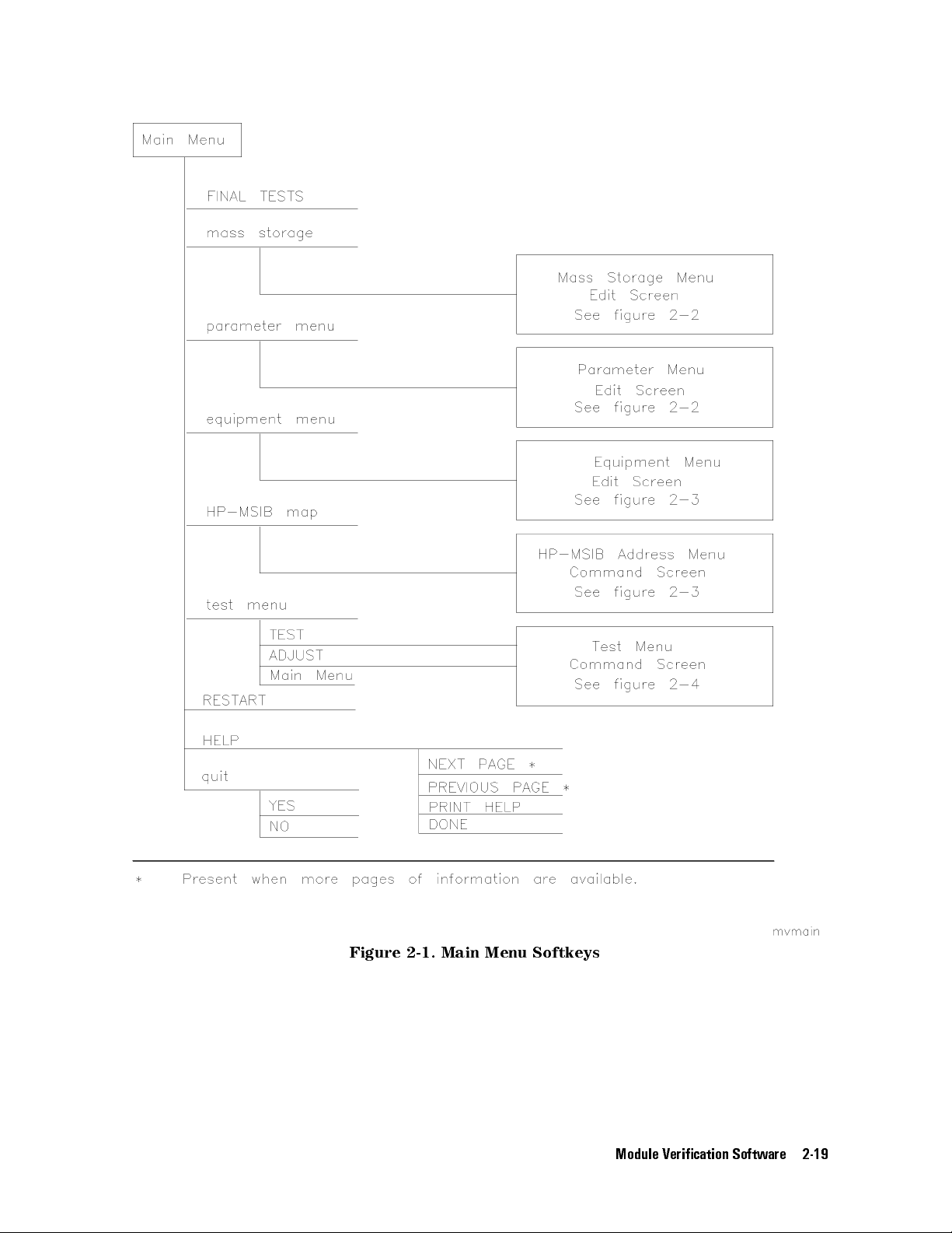
Figure 2-1. Main Menu Softkeys
Module Verication Software 2-19

Figure 2-2. Mass Storage Menu and Parameter Menu Softkeys
2-20 Module Verication Software

Figure 2-3. Equipment Menu and HP-MSIB Map Screen Menu Softkeys
Module Verication Software 2-21

2-22 Module Verication Software
Figure 2-4. Test Menu Softkeys

Error and Status Messages
User interface messages used with HP 70000 Series software products are alphabetized in
this section. The messages are designed to provide information about test results, operator
errors, and system conditions. Refer to your
HP BASIC Language Reference
for system error
information.
Aborted
You aborted the test indicated.
EEPROM for ____ is defective.
The EEPROM needs to be replaced.
Failed
The module under test needs adjustment or repair to pass the test number indicated.
CAUTION: Passthru address is incorrect. (See Edit Screen).
The address of the microwave source is not set to 19, or the address specied in the
Equipment Menu does not match the address of the synthesized source. Return to the edit
screen of the Equipment Menu to modify addresses in either the address column or the
private bus column.
CAUTION: Some Model #'s are not supported. (See Edit Screen).
You have model numbers in the Equipment Menu that are not supported by the software
Ignore this caution if you are sure program memory contains a driver for these models
A driver that is required but missing causes the error message
subprogram
to appear on-screen. You are returned to the Test Menu.
Undefined function or
Equipment list is not acceptable.
You attempted to enter the Test Menu, but the program could not locate all the instruments
for which you have specied HP-IB addresses.Verify that the indicated equipment is turned
on, then return to the Equipment Menu edit screen to verify accuracy of addresses that are
ashing in either the address column or the private bus column.
Equipment list shows no analyzer to test.
The DUT has no assigned HP-IB address. Return to the Equipment Menu and edit the
Address column.
ERROR: Address matches system disk drive
.
You entered an HP-IB address matching that of the computer's external disk drive. HP-IB
protocol allows only one instrument per address.
Address not in acceptable range.
You entered an HP-IB address outside the range 700 to 730, inclusive.
ERROR: Duplicate HP-IB address.
You attempted to exit the Equipment Menu after assigning the same HP-IB address to
dierent model numbers. HP-IB protocol allows only one instrument per address. (It is
acceptable to assign the same address to identical model numbers, implying multiple use of
the same instrument.)
.
.
ERROR: Non-responding HP-IB address
.
You attempted to exit the Equipment Menu after assigning an HP-IB address to an
instrument not responding on HP-IB.
Module Verication Software 2-23

ERROR: Search for ____ unsuccessful.
The program tried to nd the disk identied but could not. Either assign a drive to the disk
and press
NNNNNNNNNNNNNNNNNNNN
REPEAT
or insert the required disk into its appropriate drive. Press
NNNNNNNNNNNNNNNNNNNN
REPEAT
ERROR: Some devices listed as Available require serial numbers.
NNNNNNNNNNNNNNNNNNNNNNNNNNNNNNNNNNNNNNNNN
You pressed
View Cal Data
, then selected a device to which you have not assigned a
required serial number. Display the Equipment Menu edit screen and assign the serial
number.
ERROR MESSAGE: Address is HP-IB controller address.
You entered an HP-IB address matching the computer's address. HP-IB protocol allows only
one instrument per address.
ERROR MESSAGE: Attempt to close file ____ failed.
There is a problem with the data le on the Operating Disk. Correct the problem, then do
one of the following:
NNNNNNNNNNNNNNNNNNNN
Press
REPEAT
to try again.
NNNNNNNNNNNNNNNNNNNN
Press
CREATE
to create a new le.
NNNNNNNNNNNNNNNNN
Press
ABORT
to return to the Main Menu.
ERROR MESSAGE: Attempt to create file ____ failed.
There is a problem with the data le on the Operating Disk. Correct the problem, then do
one of the following:
N
Press
NNNNNNNNNNNNNNNNNNN
REPEAT
to try again.
NNNNNNNNNNNNNNNNNNNN
Press
CREATE
to create a new le.
NNNNNNNNNNNNNNNNN
Press
ABORT
to return to the Main Menu.
.
ERROR MESSAGE: Attempt to Edit Mass Storage failed.
Your edits to the Mass Storage Menu were not valid. Return to this menu and correct the
errors.
ERROR MESSAGE: Attempt to store Mass Storage failed.
You pressed
NNNNNNNNNNNNNNNNN
Press
ABORT
NNNNNNNNNNNNNNNNN
ABORT
after pressing
to return to the Main Menu.
NNNNNNNNNNNNNNNNN
STORE
mass storage. The Mass Storage Menu failed.
ERROR MESSAGE: Bad instrument address in equipment list. Address matches
controller.
You entered an HP-IB address matching that of the controller
. HP-IB protocol allows only
one instrument per address and only one controller per HP-IB system. (The factory preset
controller address is 21.)
ERROR MESSAGE: Calibration data frequency exceed acceptable limits.
Return to the Calibration Data edit screen and correct the data entries that are ashing.
ERROR MESSAGE: Calibration data frequency is less than minimum range of ____.
The frequency entered next to the device in the Cal Data edit screen is out of the device's
operating range. The return to this screen is automatic
. Enter valid frequencies for the
values that are ashing.
2-24 Module Verication Software

ERROR MESSAGE: Calibration data frequency is greater than maximum range of ____.
The frequency entered next to the device in the Cal Data edit screen is out of the device's
operating range. The return to this screen is automatic. Enter valid frequencies for the
values that are ashing.
ERROR MESSAGE: Calibration data for ____ is blank for some frequencies listed.
Return to the Calibration Data edit screen to enter the calibration data for frequencies
indicated with ashing markers.
ERROR MESSAGE: Calibration data for ____ is less than minimum range of ____.
The factor entered next to the device in the Cal Data edit screen is out of the device's
operating range. The return to this screen is automatic. Enter valid values for the ones that
are ashing.
ERROR MESSAGE: Calibration data for ____ is greater than maximum range of ____.
The factor entered next to the device in the Cal Data edit screen is out of the device's
operating range. The return to this screen is automatic. Enter valid values for the ones that
are ashing.
ERROR MESSAGE: Calibration data file not found for ____ with serial number ____.
The data le cannot be found or there is a problem with the data le on the Operating Disk.
Correct the problem, then either press
NNNNNNNNNNNNNNNNNNNN
REPEAT
to try again or press
4
CONTINUE
5
.
ERROR MESSAGE: DUT does not have an address.
You attempted to leave the Test Equipment Menu, but the program cannot verify the DUT
at the specied HP-IB address. First check the address. If the address is correct, cycle the
main power of the system under test.
ERROR MESSAGE: DUT was not at address in the equipment list. DUT was expected at
address ____.
The DUT is not at the specied address, or HP-IB is at fault, or main power is o on the
DUT. Press
NNNNNNNNNNNNNNNNN
ABORT
, then return to the Equipment Menu to verify the address
.
ERROR MESSAGE: DUT was not found at address in equipment list.
NNNNNNNNNNNNNNNNN
The address specied for the DUT is not valid. Press
ABORT
, then return to the Equipment
Menu to verify the address.
ERROR MESSAGE: Equipment address matches external disk drive.
You entered an equipment address matching that of the external disk drive. HP-IB protocol
allows only one instrument per address.
ERROR MESSAGE: Equipment Menu data not found on ____.
The program could not nd the Equipment Menu data le on the Operating Disk.
Fix
instructions appear with the on-screen error message. If the data le is available in a
Possible
location other than the one currently specied in the Mass Storage Menu, return to that
menu and change the msus and/or the directory path of the Operating Disk. It may also be
that the Operating Disk accessed by the program is not the one containing the Equipment
Menu le. Insert the correct Operating Disk, then press
NNNNNNNNNNNNNNNNNNNN
REPEATor4
CONTINUE
5
.
ERROR MESSAGE: Equipment does not have an address.
There is no address assigned to the DUT
. Return to the Equipment Menu edit screen and
verify or enter an address in the Address column.
ERROR MESSAGE: ERROR XXX in XXXXX ____ .
Module Verication Software 2-25
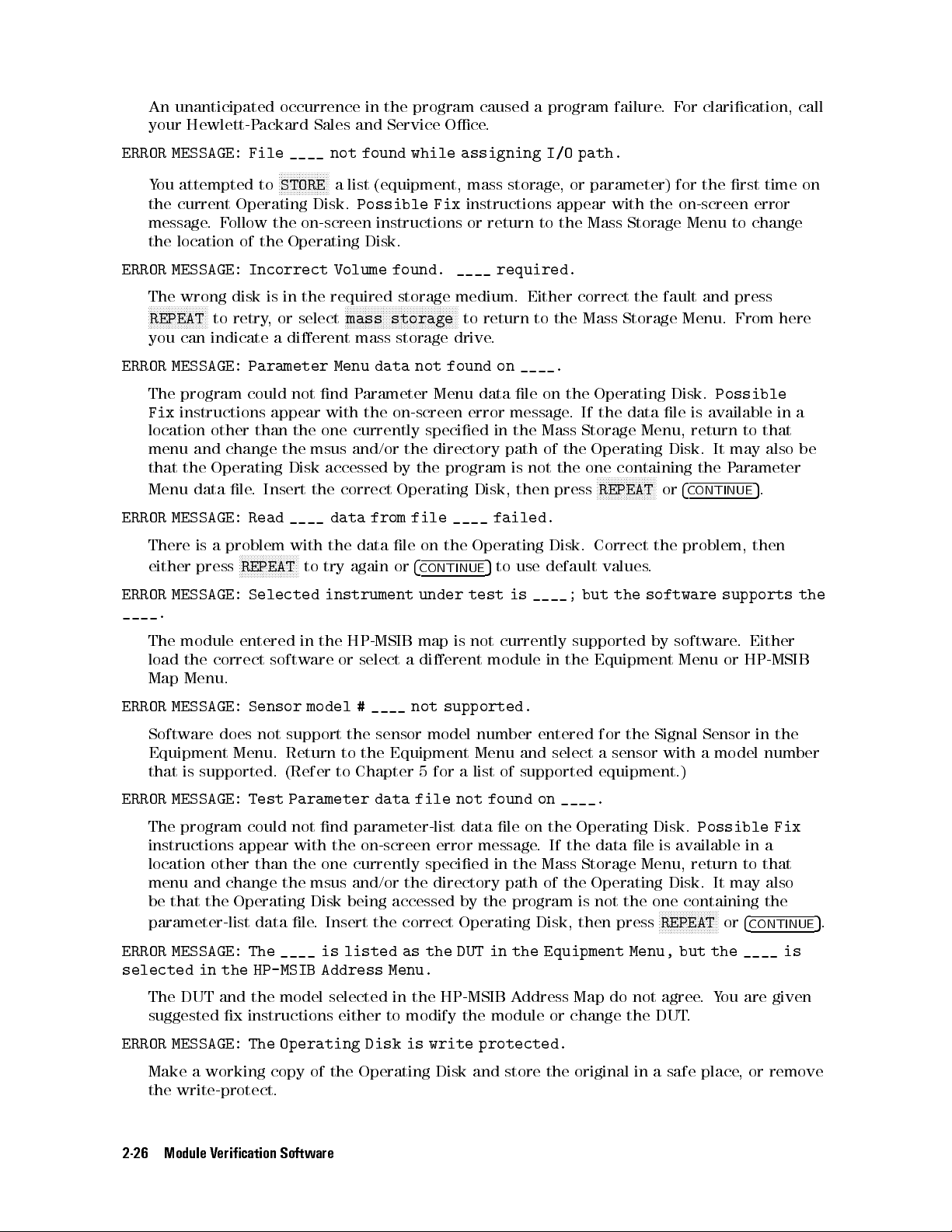
An unanticipated occurrence in the program caused a program failure.For clarication, call
your Hewlett-Packard Sales and Service Oce.
ERROR MESSAGE: File ____ not found while assigning I/O path.
NNNNNNNNNNNNNNNNN
You attempted to
the current Operating Disk.
STORE
a list (equipment, mass storage, or parameter) for the rst time on
Possible Fix
instructions appear with the on-screen error
message.Follow the on-screen instructions or return to the Mass Storage Menu to change
the location of the Operating Disk.
ERROR MESSAGE: Incorrect Volume found. ____ required.
The wrong disk is in the required storage medium. Either correct the fault and press
NNNNNNNNNNNNNNNNNNNN
REPEAT
to retry, or select
NNNNNNNNNNNNNNNNNNNNNNNNNNNNNNNNNNNNNN
mass storage
to return to the Mass Storage Menu. From here
you can indicate a dierent mass storage drive.
ERROR MESSAGE: Parameter Menu data not found on ____.
The program could not nd Parameter Menu data le on the Operating Disk.
Fix
instructions appear with the on-screen error message. If the data le is available in a
Possible
location other than the one currently specied in the Mass Storage Menu, return to that
menu and change the msus and/or the directory path of the Operating Disk. It may also be
that the Operating Disk accessed by the program is not the one containing the P
Menu data le. Insert the correct Operating Disk, then press
NNNNNNNNNNNNNNNNNNNN
REPEATor4
CONTINUE
arameter
5
.
ERROR MESSAGE: Read ____ data from file ____ failed.
There is a problem with the data le on the Operating Disk. Correct the problem, then
either press
NNNNNNNNNNNNNNNNNNNN
REPEAT
to try again or
4
CONTINUE
5
to use default values.
ERROR MESSAGE: Selected instrument under test is ____; but the software supports the
____.
The module entered in the HP-MSIB map is not currently supported by software
. Either
load the correct software or select a dierent module in the Equipment Menu or HP-MSIB
Map Menu.
ERROR MESSAGE: Sensor model # ____ not supported.
Software does not support the sensor model number entered for the Signal Sensor in the
Equipment Menu. Return to the Equipment Menu and select a sensor with a model number
that is supported. (Refer to Chapter 5 for a list of supported equipment.)
ERROR MESSAGE: Test Parameter data file not found on ____.
The program could not nd parameter-list data le on the Operating Disk.
Possible Fix
instructions appear with the on-screen error message. If the data le is available in a
location other than the one currently specied in the Mass Storage Menu, return to that
menu and change the msus and/or the directory path of the Operating Disk. It may also
be that the Operating Disk being accessed by the program is not the one containing the
parameter-list data le. Insert the correct Operating Disk, then press
NNNNNNNNNNNNNNNNNNNN
REPEATor4
CONTINUE
5
.
ERROR MESSAGE: The ____ is listed as the DUT in the Equipment Menu, but the ____ is
selected in the HP-MSIB Address Menu.
The DUT and the model selected in the HP-MSIB Address Map do not agree.You are given
suggested x instructions either to modify the module or change the DUT.
ERROR MESSAGE: The Operating Disk is write protected.
Make a working copy of the Operating Disk and store the original in a safe place
, or remove
the write-protect.
2-26 Module Verication Software
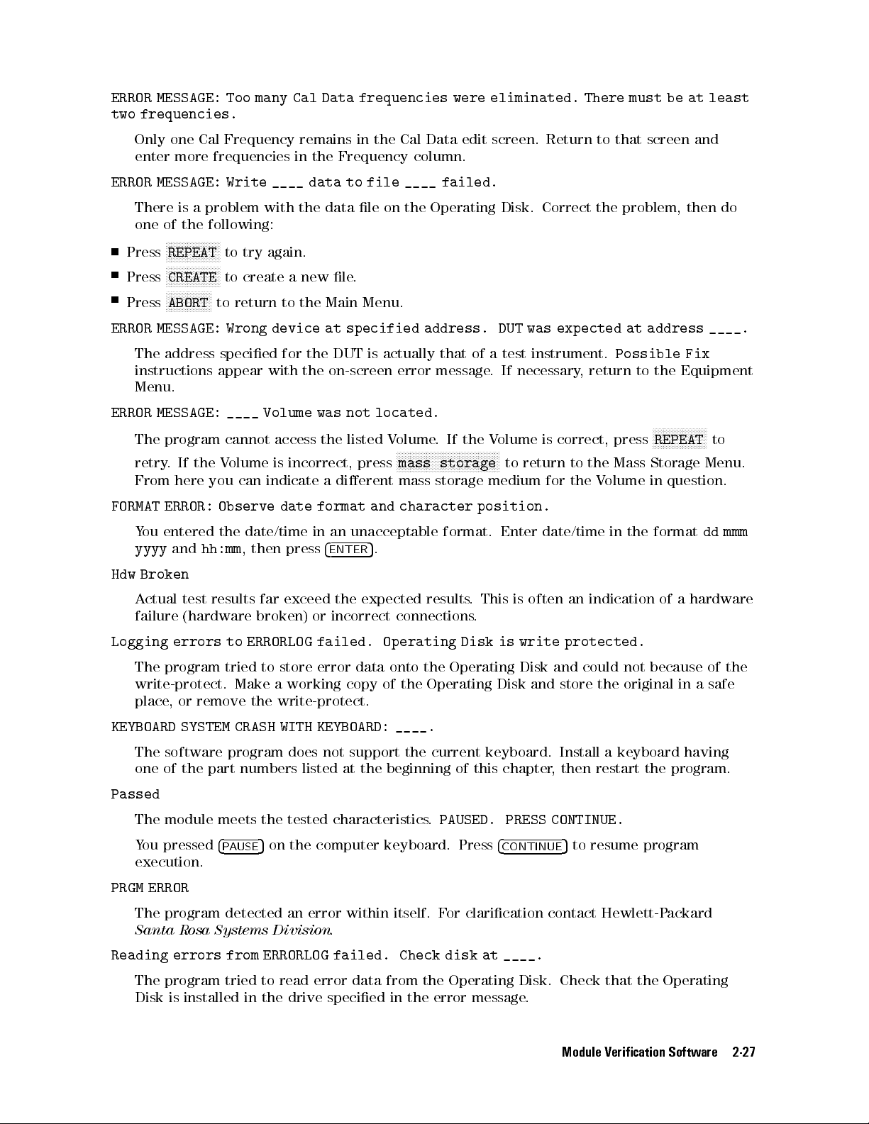
ERROR MESSAGE: Too many Cal Data frequencies were eliminated. There must be at least
two frequencies.
Only one Cal Frequency remains in the Cal Data edit screen. Return to that screen and
enter more frequencies in the Frequency column.
ERROR MESSAGE: Write ____ data to file ____ failed.
There is a problem with the data le on the Operating Disk. Correct the problem, then do
one of the following:
NNNNNNNNNNNNNNNNNNNN
Press
REPEAT
to try again.
NNNNNNNNNNNNNNNNNNNN
Press
Press
CREATE
N
NNNNNNNNNNNNNNNN
ABORT
to create a new le.
to return to the Main Menu.
ERROR MESSAGE: Wrong device at specified address. DUT was expected at address ____.
The address specied for the DUT is actually that of a test instrument.
Possible Fix
instructions appear with the on-screen error message. If necessary, return to the Equipment
Menu.
ERROR MESSAGE: ____ Volume was not located.
NNNNNNNNNNNNNNNNNNNN
The program cannot access the listed Volume. If the Volume is correct, press
retry. If the Volume is incorrect, press
From here you can indicate a dierent mass storage medium for the V
NNNNNNNNNNNNNNNNNNNNNNNNNNNNNNNNNNNNNN
mass storage
to return to the Mass Storage Menu.
olume in question.
REPEAT
FORMAT ERROR: Observe date format and character position.
You entered the date/time in an unacceptable format. Enter date/time in the format
yyyy
and
hh:mm
, then press
4
ENTER
5
.
Hdw Broken
Actual test results far exceed the expected results. This is often an indication of a hardware
failure (hardware broken) or incorrect connections.
Logging errors to ERRORLOG failed. Operating Disk is write protected.
The program tried to store error data onto the Operating Disk and could not because of the
write-protect. Make a working copy of the Operating Disk and store the original in a safe
place, or remove the write-protect.
KEYBOARD SYSTEM CRASH WITH KEYBOARD: ____.
The software program does not support the current keyboard. Install a keyboard having
one of the part numbers listed at the beginning of this chapter, then restart the program.
to
dd mmm
Passed
The module meets the tested characteristics.
You pressed
4
PAUSE
5
on the computer keyboard. Press
PAUSED. PRESS CONTINUE.
4
CONTINUE
5
to resume program
execution.
PRGM ERROR
The program detected an error within itself. For clarication contact Hewlett-Packard
Santa Rosa Systems Division
.
Reading errors from ERRORLOG failed. Check disk at ____.
The program tried to read error data from the Operating Disk. Check that the Operating
Disk is installed in the drive specied in the error message
.
Module Verication Software 2-27
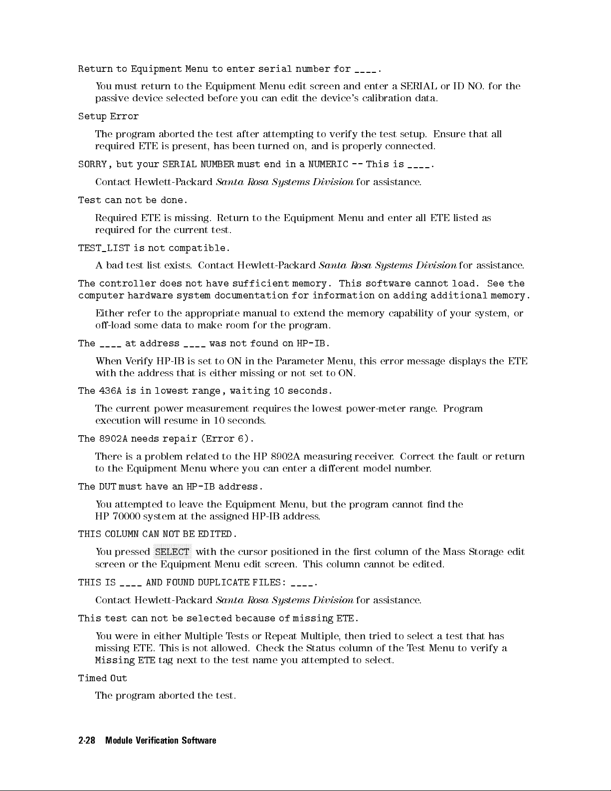
Return to Equipment Menu to enter serial number for ____.
You must return to the Equipment Menu edit screen and enter a SERIAL or ID NO. for the
passive device selected before you can edit the device's calibration data.
Setup Error
The program aborted the test after attempting to verify the test setup. Ensure that all
required ETE is present, has been turned on, and is properly connected.
SORRY, but your SERIAL NUMBER must end in a NUMERIC -- This is ____.
Contact Hewlett-Packard
Santa Rosa Systems Division
for assistance.
Test can not be done.
Required ETE is missing. Return to the Equipment Menu and enter all ETE listed as
required for the current test.
TEST_LIST is not compatible.
A bad test list exists. Contact Hewlett-Packard
Santa Rosa Systems Division
for assistance.
The controller does not have sufficient memory. This software cannot load. See the
computer hardware system documentation for information on adding additional memory.
Either refer to the appropriate manual to extend the memory capability of your system, or
o-load some data to make room for the program.
The ____ at address ____ was not found on HP-IB.
When Verify HP-IB is set to ON in the P
arameter Menu, this error message displays the ETE
with the address that is either missing or not set to ON.
The 436A is in lowest range, waiting 10 seconds.
The current power measurement requires the lowest power-meter range
. Program
execution will resume in 10 seconds.
The 8902A needs repair (Error 6).
There is a problem related to the HP 8902A measuring receiver
to the Equipment Menu where you can enter a dierent model number
. Correct the fault or return
.
The DUT must have an HP-IB address.
You attempted to leave the Equipment Menu, but the program cannot nd the
HP 70000 system at the assigned HP-IB address.
THIS COLUMN CAN NOT BE EDITED.
NNNNNNNNNNNNNNNNNNNN
You pressed
SELECT
with the cursor positioned in the rst column of the Mass Storage edit
screen or the Equipment Menu edit screen. This column cannot be edited.
THIS IS ____ AND FOUND DUPLICATE FILES: ____.
Contact Hewlett-Packard
Santa Rosa Systems Division
for assistance.
This test can not be selected because of missing ETE.
You were in either Multiple Tests or Repeat Multiple, then tried to select a test that has
missing ETE. This is not allowed. Check the Status column of the Test Menu to verify a
Missing ETE
tag next to the test name you attempted to select.
Timed Out
The program aborted the test.
2-28 Module Verication Software
WARNING: Duplicate Address
You entered a duplicate HP-IB address to an item in the Equipment Menu. (You may have
to scroll through the menu to nd the duplication.)
WARNING: Duplication may exclude specific tests.
You assigned two generic device functions to one ETE. (For example, the TOI test will not
be run if you assign a single HP 3335A synthesizer/level generator as both the required level
generator and the required general source.)
WARNING: String is too long. It has been truncated.
You entered too many characters in a user's line of the Parameter Menu edit screen. Select
the line and enter 30 or fewer characters.
Write protected.
You attempted to store data on a write-protected disk. After correcting the fault, press
4
CONTINUE
5
.
Module Verication Software 2-29


3
Before Extensive Servicing
This chapter contains information to help identify and resolve some common problems that
may occur with your HP 70900B local oscillator source before extensive servicing.
Symptoms to various problems are listed at the top of each page. Most symptoms have a brief
description or explanation to help provide more insight into their cause. A possible cause for
the symptom and a checklist of possible solutions are then presented. Use this checklist as an
aid to correct the problem.
If you determine that your HP 70900B local oscillator source needs further servicing and
your HP 70900B local oscillator source is not experiencing any of the symptoms presented in
this chapter, refer to \Performing Related Adjustments and Verication Tests" in Chapter 4 to
determine which adjustments and verication tests must be performed and also Table 5-1 for a
list of recommended test equipment to use when assemblies are changed, repaired, or adjusted.
Note
If you decide to perform the servicing yourself, prepare a static-safe work
station before you begin any servicing procedures. (Refer to \Preparing
a Static-Safe Work Station" in Chapter 4.) If you do not wish to perform
the servicing yourself, return your HP 70900B local oscillator source to a
Hewlett-Packard service center. (Refer to \If You Want Hewlett-Packard to
Service Your Local Oscillator Source" in Chapter 1.)
Before Extensive Servicing 3-1
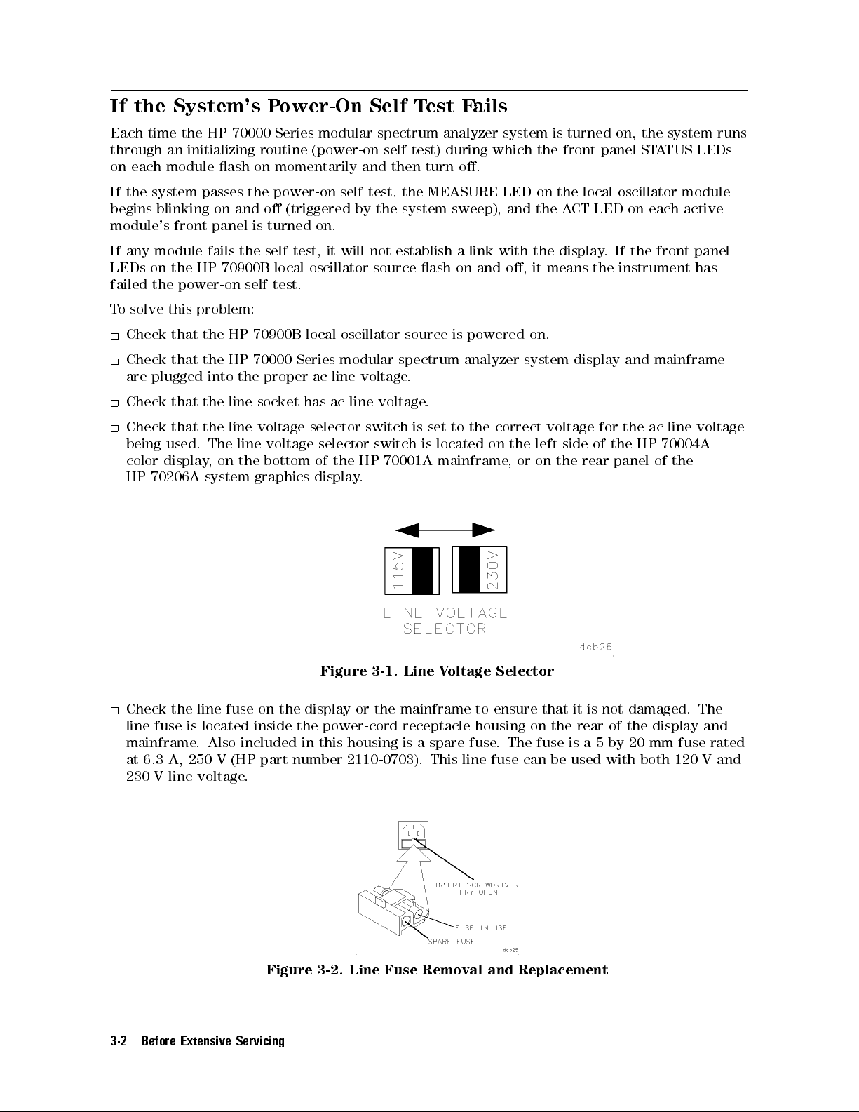
If the System's Power-On Self Test Fails
Each time the HP 70000 Series modular spectrum analyzer system is turned on, the system runs
through an initializing routine (power-on self test) during which the front panel STATUS LEDs
on each module ash on momentarily and then turn o.
If the system passes the power-on self test, the MEASURE LED on the local oscillator module
begins blinking on and o (triggered by the system sweep), and the ACT LED on each active
module's front panel is turned on.
If any module fails the self test, it will not establish a link with the display. If the front panel
LEDs on the HP 70900B local oscillator source ash on and o, it means the instrument has
failed the power-on self test.
To solve this problem:
Check that the HP 70900B local oscillator source is powered on.
Check that the HP 70000 Series modular spectrum analyzer system display and mainframe
are plugged into the proper ac line voltage.
Check that the line socket has ac line voltage.
Check that the line voltage selector switch is set to the correct voltage for the ac line voltage
being used. The line voltage selector switch is located on the left side of the HP 70004A
color display, on the bottom of the HP 70001A mainframe
HP 70206A system graphics display.
, or on the rear panel of the
Figure 3-1. Line Voltage Selector
Check the line fuse on the display or the mainframe to ensure that it is not damaged. The
line fuse is located inside the power-cord receptacle housing on the rear of the display and
mainframe. Also included in this housing is a spare fuse. The fuse is a 5 by 20 mm fuse rated
at 6.3 A, 250 V (HP part number 2110-0703). This line fuse can be used with both 120 V and
230 V line voltage.
Figure 3-2. Line Fuse Removal and Replacement
3-2 Before Extensive Servicing
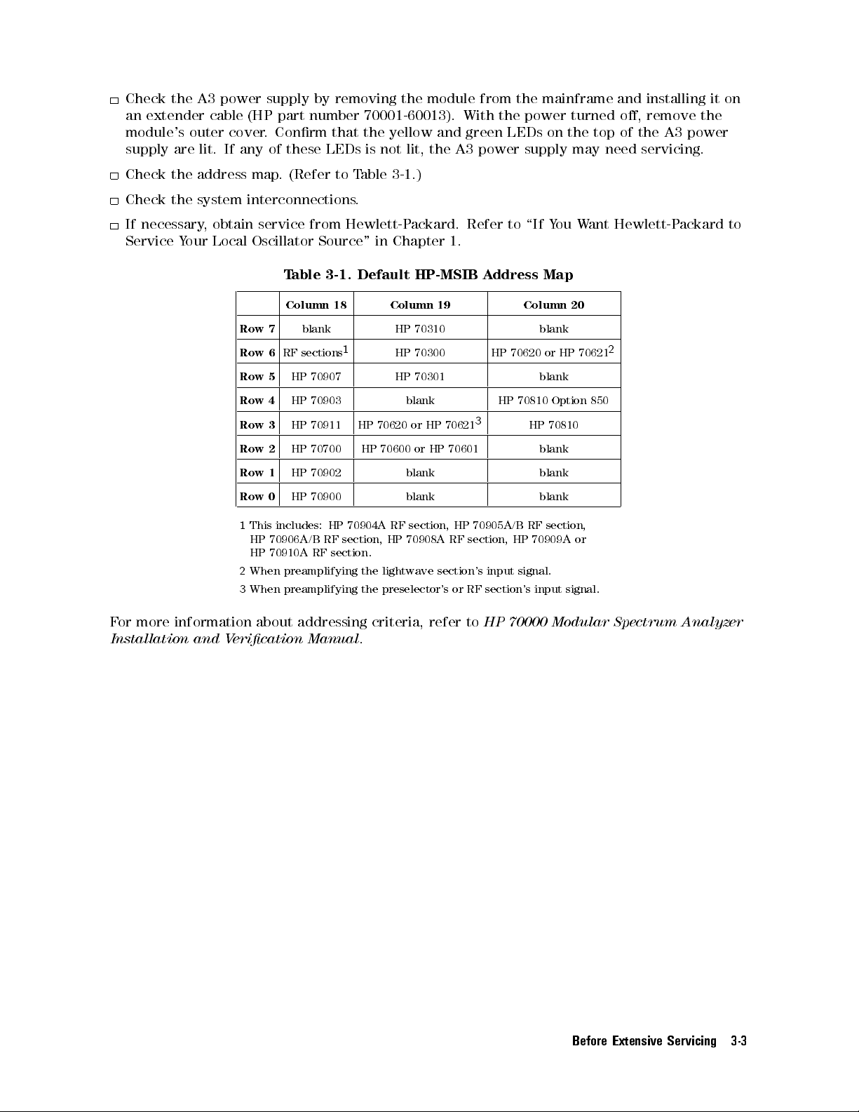
Check the A3 power supply by removing the module from the mainframe and installing it on
an extender cable (HP part number 70001-60013). With the power turned o, remove the
module's outer cover. Conrm that the yellow and green LEDs on the top of the A3 power
supply are lit. If any of these LEDs is not lit, the A3 power supply may need servicing.
Check the address map. (Refer to Table 3-1.)
Check the system interconnections.
If necessary, obtain service from Hewlett-Packard. Refer to \If You Want Hewlett-Packard to
Service Your Local Oscillator Source" in Chapter 1.
Table 3-1. Default HP-MSIB Address Map
Column 18 Column 19 Column 20
Row 7
Row 6
Row 5
Row 4
Row 3
Row 2
Row 1
Row 0
1
This includes: HP 70904A RF section, HP 70905A/B RF section,
blank HP 70310 blank
RF sections
1
HP 70300 HP 70620 or HP 70621
HP 70907 HP 70301 blank
HP 70903 blank HP 70810 Option 850
HP 70911 HP 70620 or HP 70621
HP 70700 HP 70600 or HP 70601 blank
HP 70902 blank blank
HP 70900 blank blank
HP 70906A/B RF section , HP 70908A RF section , HP 70909A or
HP 70910A RF section.
2
When preamplifying the lightwave section's input signal.
3
When preamplifying the preselector's or RF section's input signal.
For more information about addressing criteria, refer to
Installation and Verication Manual
.
2
3
HP 70810
HP 70000 Modular Spectrum Analyzer
Before Extensive Servicing 3-3

If Your HP 70900B Local Oscillator Source Is Powered On But
Not Responding Correctly
Many dierent things could cause this type of symptom.
To solve this problem:
Check the HP 70000 Series modular spectrum analyzer system display for error messages.
Check the address map to see that the HP 70900B local oscillator source is located at
row 0, column 18. All other modules should be in the order given in the address map
guidelines. (Refer to Table 3-1.)
Check that other modules in the system, cables, and connectors are connected and operating
correctly.
If necessary, obtain service from Hewlett-Packard. (Refer to \If You Want Hewlett-Packard to
Service Your Local Oscillator Source" in Chapter 1.)
3-4 Before Extensive Servicing
If the STATUS ERR Indicator LED on the HP 70900B Local
Oscillator Source is Flashing
The HP 70900B local oscillator source communicates with the HP 70000 Series modular
spectrum analyzer system over the HP-MSIB. When the STATUS ERR indicator LED on the
HP 70900B local oscillator source ashes at a 1 Hz rate, the module cannot communicate over
the HP-MSIB.
To solve this problem:
Try turning o the power to the system and then turning it on again.
If front panel keys are still responding, check the address map to see that all modules are
located in their designated coordinates.
If front panel keys are not responding and the address map cannot be checked, power-down
the system, pull out each module and check its address setting by looking at its address
switches.
All modules should conform to the required coordinates on the address map. (Refer to
Table 3-1.)
If your system contains more than one mainframe, check that the HP-MSIB cables are
connected such that two cable connections are made to each mainframe
connections look correct, you may try replacing the HP-MSIB cables with new ones
If necessary, obtain service from Hewlett-Packard. (Refer to \If You Want Hewlett-Packard to
Service Your Local Oscillator Source" in Chapter 1.)
. If these cable
.
Before Extensive Servicing 3-5

If More Than One Module's Error Indicator Is Flashing
The HP 70900B local oscillator source communicates with the HP 70000 Series modular
spectrum analyzer system over the HP-MSIB. When the STATUS ERR indicator LED on a
particular module ashes at a 1 Hz rate, the module cannot communicate over the HP-MSIB.
To solve this problem:
Try turning o the power to the system and then turning it on again.
If front panel keys are still responding, check the address map to see that all modules are
located in their designated coordinates.
If front panel keys are not responding and the address map cannot be checked, power-down
the system, pull out each module and check its address setting by looking at its address
switches.
All modules should conform to the required coordinates on the address map. (Refer to
Table 3-1 .)
If your system contains more than one mainframe, check that the HP-MSIB cables are
connected such that two cable connections are made to each mainframe. If these cable
connections look correct, you may try replacing the HP-MSIB cables with new ones
If necessary, obtain service from Hewlett-Packard. (Refer to \If You Want Hewlett-Packard to
Service Your Local Oscillator Source" in Chapter 1.)
.
3-6 Before Extensive Servicing

4
Troubleshooting
This chapter contains information about troubleshooting your local oscillator source . It presents
information on preparing a static-safe work station and then it presents a set of troubleshooting
procedures that can be used to optimize repair time.
A ow chart (as shown in Figure 4-2) directs you to the appropriate troubleshooting
procedures.
A listing of adjustments and verication tests that must be performed, as well as the
recommended test equipment that should be used when assemblies are changed, repaired, or
adjusted are presented at the end of this chapter.
Troubleshooting 4-1

Preparing a Static-Safe Work Station
Electrostatic discharge (ESD) can damage or destroy electronic components. Therefore,
all work performed on assemblies consisting of electronic components should be done at a
static-safe work station.
Figure 4-1 shows an example of a static-safe work station. Two types of ESD protection are
shown:
a conductive table mat and wrist strap combination
a conductive oor mat and heel strap combination
Figure 4-1. Static-Safe Work Station
These two types of ESD protection must be used together. Refer to Table 4-1 for a list of
static-safe accessories and their HP part numbers.
CAUTION
4-2 Troubleshooting
Do not touch the edge-connector contacts or trace surfaces with bare hands
Always handle board assemblies by the edges.
Do not use erasers to clean the edge-connector contacts. Erasers generate
static electricity and degrade the electrical quality of the contacts by
removing the thin gold plating.
Do not use paper of any kind to clean the edge-connector contacts.Paper or
lint particles left on the contact surface can cause intermittent electrical
connections.
.

Preparing a Static-Safe Work Station
Reducing ESD Damage
To help reduce the amount of ESD damage that occurs during testing and servicing use the
following guidelines:
Be sure that all instruments are properly earth-grounded to prevent buildup of static charge.
Personnel should be grounded with a resistor-isolated wrist strap before touching the center
pin of any connector and before removing any assembly from a piece of equipment.
Use a resistor-isolated wrist strap that is connected to the HP 70000 Series modular spectrum
analyzer system mainframe's chassis. If you do not have a resistor-isolated wrist strap, touch
the chassis frequently to equalize any static charge.
Before connecting any coaxial cable to an instrument connector for the rst time each day,
momentarily
short the center and outer conductors of the cable together.
Handle all PC board assemblies and electronic components only at static-safe work stations.
Store or transport PC board assemblies and electronic components in static-shielding
containers.
PC board assembly edge-connector contacts may be cleaned by using a lintfree cloth with a
solution of 80% electronics-grade isopropyl alcohol and 20% deionized water
. This procedure
should be performed at a static-safe work station.
Static-Safe ESD Accessories
Table 4-1. Static-Safe ESD Accessories
HP Part
Description
Number
2
9300-0797 Set includes: 3M static control mat 0.6 m
1.2m(2ft24 ft) and 4.6 m
(15 ft) ground wire. (The wrist-strap and wrist-strap cord are not included.
They must be ordered separately.)
9300-0865 Ground wire, 4.6 m (15 ft)
9300-0980 Wrist-strap cord 1.5 m (5 ft)
9300-1383 Wrist-strap, color black, stainless steel, without cord, has four adjustable
links and a 7 mm post-type connection.
9300-1169 ESD heel-strap (reusable 6 to 12 months).
Order the following by calling HP DIRECT at (800) 538-8787 or through any Hewlett-P
Sales and Service Oce.
ackard
Troubleshooting 4-3

Troubleshooting Flow Chart
The (\Troubleshooting Flow Chart") for the HP 70900B local oscillator source directs you to
troubleshooting procedures in this chapter. The major decision blocks are described in the
following sections.
Figure 4-2. Troubleshooting Flow Chart
Does the Module Complete Power-Up?
The power-up sequence is performed automatically by the local oscillator source each time
power is applied. If the local oscillator source can't complete its power-up sequence, it will not
establish a link with the display. If this happens, all local oscillator source front panel LEDs
will ash on and o. (Refer to \If the System's Power-On Self Test Fails" in Chapter 3.)
4-4 Troubleshooting

Troubleshooting Flow Chart
Any Errors from the Analyzer Test?
To perform the analyzer-test sequence, press
NNNNNNNNNNNNNNNNNNNNNNNNNNNNNNNNNNNNNNNNN
ANALYZER TEST
on the system display. Always wait at least 30 seconds after power-up
before performing the analyzer-test sequence.
4
5
MENU
MISC
NNNNNNNNNNNNNNNNNNNNNNNNNNNNNNNNNNNNNNNNN
Analyzer Test
NNNNNNNNNNNNNN
NNNNNNNNNNNNNN
,
MORE
NNNNNNNNNNNNNNNNNNNNNNN
,
SERVICE
, and
checks for the presence of
key reference signals, the ability of the three phase-lock loops to lock at their maximum and
minimum points, the linearity of all digital-to-analog converters (DACs), and analog-to-digital
converter (ADC) performance.
Can the Symptom Be Observed on the LO Output?
Reaching this point in the troubleshooting ow chart means the local oscillator source's
three phase-lock loops (PLLs) can lock. These PLLs are the A4 idler phase-lock loop, A6 YTO
phase-lock loop/A8 frequency control, and A7 FRAC'N synthesizer. Any remaining problems
are likely due to noise or sidebands, frequency-dependent unlocks, intermittent unlocks, faulty
rear panel outputs, or video detector failures. Can noise, sidebands, or unlock conditions be
observed on the local oscillator source 's rear panel LO signal? (The rear panel jack is A6A4
YTO lock microcircuit (J3).) If the symptom is present at A6A4 YTO lock microcircuit (J3),
observe the idler output. If the symptom is not present, observe the 300 MHz rear panel output
to verify that it meets its amplitude specication.
Can the Symptom Be Observed on the Idler Output?
Place the local oscillator source on an HP 70001-60013 extender module
. Remove the
local oscillator source cover. Can the noise, sidebands, or unlock conditions be observed on
the idler signal at A4A3 idler VCO microcircuit (J2)? If the symptom cannot be observed,
the problem is in the YTO lock loop. If it is observed at A4A3 idler V
CO microcircuit (J2),
inspect the signal at A7A1 FFS phase lock loop (J1). If the symptom is observed at A7A1
FFS phase lock loop (J1), refer to \A7 FRA
C'N Synthesizer Troubleshooting". If the symptom
is not observed at A7A1 FFS phase lock loop (J1), refer to \A4 Idler Phase-Lock Loop
Troubleshooting".
Can the Symptom Be Observed on the Rear-Panel 300 MHz Output?
Can the symptoms be observed on the two rear panel 300 MHz outputs? Measure the power of
the 300 MHz front panel calibrator signal. The power should be010 dBm60.3 dB.
Is the A2 Video Processor OK?
Perform the following steps to test the A2 video processor:
1. Set an HP 3325B synthesized function/sweep generator to the following settings:
FREQ
AMPTD
:::::: ::::::: ::::::: :::::: ::::::: ::::::: ::::::::::::: ::::::: ::::::: :::::: ::::: ::::::
:::::: :::::: ::::::: ::::::: :::::: ::::::: ::::::::::::: ::::::: ::::::: ::::::: :::: :::::::
DC OFFSET
FUNCTION
::::::: ::::::: :::::: ::::::: ::::::: :::::: :::::::::::::: :::::: ::::::: ::::::: :::: ::
::::: ::::::: :::::: ::::::: ::::::: :::::: :::::::::::::: :::::: ::::::: ::::
Triangle wave
20 Hz
2V
1V
2. Set the HP 70900B local oscillator source to the following settings:
SPAN
SWEEP TIME
SWEEP
Cal corrections
EXTERNAL TRIGGER
::::::: :::::: ::::::: ::::::: ::::::: :::::: :::::::::::::: :::::: ::::::: ::::::: :::: :::::::
::::::: ::::::: :::::: ::::::: ::::::: :::::: :::::::::::::: :::::: ::::::: ::::::: :
::::::: ::::::: :::::: ::::::: ::::::: :::::: :::::::::::::: :::::: ::::::: ::::::
:::::: ::::::: :::::: ::::::: ::::::: :::::: :::::::::::::: :::::: ::::::: ::::
::::::: ::::::: :::::: ::::::: ::::::: :::::: :::::::::::::: :::::: ::::::: ::
0Hz
60 ms
CONTINUOUS
ALL OFF
ON
Troubleshooting 4-5
Troubleshooting Flow Chart
3. Connect the front panel SYNC OUT of the HP 3325B synthesized function/sweep generator
to the HP 70900B local oscillator source's rear panel EXT TRIG. Connect the HP 3325B
synthesized function/sweep generator SIGNAL output to the HP 70900B local oscillator
source's rear panel VIDEO jack.
4. Verify that the triangle wave on the spectrum analyzer's display is linear. Check the
analog-to-digital converter bits. If necessary, use the dB/DIV and reference level to expand
the scale to inspect the least signicant bit (LSB). (1 LSB0.27 dB500V.) If the CRT
display is linear, either the A2 video processor or the A1A1 host/processor is faulty.
5. Check the detectors on the A2 video processor. With a signal on the screen and a span less
than 10 MHz, press the
SAMPLE, and NORMAL detectors all give similar amplitude readings in the uncorrected
mode (61 dB referenced to SAMPLE detector). If any problems are found, run the video
processor adjustment procedure described in Chapter 6. If the assembly cannot be adjusted,
change the A2 video processor.
Are the A9 Front Panel Indicators OK?
Run the LED Check verication test. If the test passes, run the remaining verication tests.
4
MENU
5
key,
NNNNNNNNNNNNNNNNN
TRACE
, then
NNNNNNNNNNNNNNNNNNNNNNNNNN
DETECTOR
.Verify that POS PK, NEGPK,
4-6 Troubleshooting
If Operating Errors Messages (2000{2999) Occur
If Operating Errors Messages (2000{2999) Occur
These operating errors occur when the processor on the A1A1 host/processor receives an
unrecognizable command.
2011
2034
Memory Overow
To solve this problem:
1. Conrm that the error is caused by the HP 70900B local oscillator source.
2. Make sure the error is not caused by a user-dened function, or any other
user-input command or program.
3. Execute a
Analyzer Programming Manual
DISPOSE ALL
command (refer to the
) and set N STATES to 0. This will erase all user
HP 70000 Modular Spectrum
input programs.
4. If the problem still exists, replace the A1A1 host/processor or A1A2 1/4 MB
RAM/ROM.
Test Switch Is On
To solve this problem:
1. Conrm that the error is caused by the HP 70900B local oscillator source
.
2. Make sure the error is not caused by a user-dened function, or any other
user-input command or program.
3. Set A1A1 host/processor (S2) switch 1 to the \1" position (open) when this error
code appears.
4. If the switch is already in the \1" position, replace the A1A1 host/processor
.
Troubleshooting 4-7
If Hardware Error Messages (7000{7999) Occur
Hardware errors are generated when a module in the HP 70000 Series modular spectrum
analyzer system is not working properly. These errors can occur at any time. Hardware errors
range from 7000{7999.
Because HP 70900B local oscillator source assemblies operate inner-dependently, a single
problem can cause multiple errors. Troubleshoot these errors in the order in which they are
reported.
One or more of the following hardware error messages may appear on your system display;
these errors can occur at any time:
7000
7001,
7002
7003
7004
ROM check
This hardware error occurs when a checksum computed on the ROM at power-up fails.
To solve this problem:
1. Replace the A1A1 host/processor or the A1A2 1/4 MB RAM/ROM.
2. If necessary, obtain service from Hewlett-Packard. (Refer to \If You Want
Hewlett-Packard to Service Your Local Oscillator Source " in Chapter 1.)
1st LO unleveled
This hardware error, sent from slave modules, indicate the LO signal is unleveled.
To solve this problem:
1. Check the LO power at A6A4 YTO lock microcircuit (J3), the rear panel LO jack.
Refer to \YTO Unlock" under \A6 YTO Phase-Lock Loop/A8 Frequency Control
Troubleshooting".
2nd LO unlocked
2nd LO unlocked
These hardware errors, sent from slave modules, indicates a second LO is unlocked.
To solve this problem:
1. Check rear panel 300 MHz outputs. (Refer to \A4 Idler Phase-Lock Loop
Troubleshooting".)
2. Check 2nd LO and 2nd Mixer in front end.
7008
FFS handshake
The A1A1 host/processor originates this hardware error when it cannot communicate
with the A7A2 FFS analog through the W14 ribbon cable
To solve this problem:
1. Refer to \A7 FRAC'N Synthesizer Troubleshooting".
7010
FFS is unlocked
This hardware error, sent from the A7A2 FFS analog to the A1A1 host/processor,
indicates the A7 FRAC'N synthesizer is unlocked. It is sent from A7A2 FFS analog (J5)
pin 11, through ribbon cable W14, when the tune voltage to the A7A1 FFS phase lock
loop exceeds limits.
To solve this problem:
1. Refer to \A7 FRAC'N Synthesizer Troubleshooting".
4-8 Troubleshooting
.
If Hardware Error Messages (7000{7999) Occur
7011
7012
125 kHz to FFS
NNNNNNNNNNNNNNNNNNNNNNNNNNNNNNNNNNNNNNNN
This hardware error, reported during a power-up or
N
Analyzer Test
sequence,
occurs when no 125 kHz signal is present at the 125 kHz detector in the A6A1 100
MHz reference. The detector converts the signal to a voltage that is sent from A6A1
100 MHz reference (J7) pin 2, through the A11 wiring harness, and to the A2 video
processor. The A1A1 host/processor reads this voltage with the analog-to-digital
converter in the A2 video processor. The error occurs also when the detected voltage
falls outside the +0.65 V to +0.85 V range.
To solve this problem:
1. Measure the voltage at A6A1 100 MHz reference (J7) pin 2. If the voltage is out of
range, the A6A1 100 MHz reference is faulty.
2. If the voltage at A6A1 100 MHz reference (J7) pin 2 is in range, measure the
voltage at A2 video processor (J3) pin 7. If this voltage is out of range, replace the
A11 wiring harness.
3. If the voltage at A2 video processor (J3) pin 7 is correct, the problem is a faulty A2
video processor.
Cannot lock YTO
This hardware error occurs when the A6 YTO phase-lock loop fails to phase lock. The
A1A1 host/processor attempts to lock the YTO at the beginning of a sweep by moving
the error voltage at A6A2 YTO lock (J2) o of the maximum or minimum rail value
.
The controller attempts to move the error voltage by changing the start-frequency
tune DAC on the A8 frequency control.
7013
To solve this problem:
1. Refer to \A6 YTO Phase-Lock Loop/A8 Frequency Control Troubleshooting".
Cannot ne tune YTO
This hardware error occurs when the A6 YTO phase-lock loop cannot be ne-tuned.
The A1A1 host/processor locks the YTO at the start of a sweep and tries to move the
error voltage at A6A2 YTO lock (J6) to 0 V by changing the start-frequency correction
DAC on the A8 frequency control.
To solve this problem:
1. Refer to \A6 YTO Phase-Lock Loop/A8 Frequency Control Troubleshooting".
Troubleshooting 4-9
If Hardware Error Messages (7000{7999) Occur
7014
7015
12.5 MHz to YTO lock
NNNNNNNNNNNNNNNNNNNNNNNNNNNNNNNNNNNNNNNN
This hardware error, reported during a power-up or
N
Analyzer Test
sequence, occurs
when no 12.5 MHz signal is present at the 12.5 MHz detector in the A6A1 100 MHz
reference. The detector converts the signal to a voltage that is sent from A6A1 100
MHz reference (J5) pin 1, through the A11 wiring harness, to the A2 video processor.
The A1A1 host/processor reads this voltage with the digital-to-analog converter in the
A2 video processor. This error occurs also when the detected voltage falls outside the
+0.65 V to +0.85 V range.
To solve this problem:
1. Measure the voltage at A6A1 100 MHz reference (J5) pin 1. If the voltage is out of
range, the A6A1 100 MHz reference is faulty.
2. If the voltage at A6A1 100 MHz reference (J5) pin 1 is in range, measure the
voltage at A2 video processor (J3) pin 6. If this voltage is out of range, replace the
A11 wiring harness.
3. If the voltage at A2 video processor (J3) pin 6 is correct, the problem is a faulty A2
video processor.
YTO is unleveled
This hardware error occurs when the A6A5 YTO output fails to level. The signal
(HYOLVL) is sent from the A6A5 YTO through W15 pin 7 to the A8 frequency control,
where it is read by the A1A1 host/processor. This error usually occurs at an LO
frequency of 3 GHz, caused by the YTO.
7016
To solve this problem:
1. Refer to \A6 YTO Phase-Lock Loop/A8 Frequency Control Troubleshooting".
YTO is unlocked
This hardware error indicates an unlocked YTO PLL. The error occurs when the error
0
voltage at A6A2 YTO lock (J6) exceeds a
9 V to +9 V range. The signal is sent from
A6A2 YTO lock (J6) to the A1A1 host/processor through the A8 frequency control.
To solve this problem:
1. Refer to \A6 YTO Phase-Lock Loop/A8 Frequency Control Troubleshooting".
4-10 Troubleshooting
If Hardware Error Messages (7000{7999) Occur
7018
7019
50 MHz to sampler
NNNNNNNNNNNNNNNNNNNNNNNNNNNNNNNNNNNNNNNNN
This hardware error is reported during a power-up or
Analyzer Test
sequence,
and occurs when no 50 MHz signal is present at the 50 MHz detector in the A6A1
100 MHz reference. The detector converts this signal to a voltage that is sent from
A6A1 100 MHz reference (J7) pin 3, through the A11 wiring harness, and to the A2
video processor. The A1A1 host/processor reads this voltage with the analog-to-digital
converter in the A2 video processor. This error also occurs when the detected voltage
falls below 0.5 V.
To solve this problem:
1. Measure the voltage at A6A1 100 MHz reference (J7) pin 3. If it is between 0.35 V
and 0.5 V, replace the A6A1 100 MHz reference. If the voltage level is less than
0.35 V, the A6A1 100 MHz reference or A6A4 YTO lock microcircuit probably are
faulty.
2. If the voltage at A6A1 100 MHz reference (J7) pin 3 is correct, measure the voltage
at A2 video processor (J3) pin 1. If the voltage is out of range, replace the A11
wiring harness.
3. If the voltage at A2 video processor (J3) pin 1 is correct, the problem is a faulty A2
video processor.
300 MHz post lter
NNNNNNNNNNNNNNNNNNNNNNNNNNNNNNNNNNNNNNNN
This hardware error is reported during a power-up or
N
Analyzer Test
sequence,
and occurs when no 300 MHz signal is present at the 300 MHz detector in the A4A1
300 MHz amplier. The detector converts this signal to a voltage that is sent from
A4A1 300 MHz amplier (J2) pin 1, through the A11 wiring harness
, to the A2 video
processor. The A1A1 host/processor reads this voltage with the analog-to-digital
converter in the A2 video processor. This error also occurs when the voltage falls
below +0.2 V.
To solve this problem:
1. Measure the voltage at A4A1 300 MHz amplier (J2) pin 1. If it is less than +0.2 V
the A4A1 300 MHz amplier is faulty.
2. If the voltage at A4A1 300 MHz amplier (J2) pin 1 is correct, measure the voltage
at A2 video processor (J3) pin 5. If the voltage is out of range, replace the A11
wiring harness.
3. If the voltage at A4A1 300 MHz amplier(J2) pin 1 is correct, the problem is a
faulty A2 video processor.
,
Troubleshooting 4-11
If Hardware Error Messages (7000{7999) Occur
7020
7021
300 MHz AGC
NNNNNNNNNNNNNNNNNNNNNNNNNNNNNNNNNNNNNNNNN
This hardware error is reported during a power-up or
Analyzer Test
sequence, and
occurs when the leveling-loop automatic gain control (AGC) voltage of the A4A1 300
MHz amplier is incorrect. The AGC voltage is sent from A4A1 300 MHz amplier
(J2) pin 2, through the A11 wiring harness, to the A2 video processor. The A1A1
host/processor reads this voltage with the analog-to-digital converter in the A2 video
processor. The error occurs when the voltage exceeds a +0.2 V to +1.5 V range.
To solve this problem:
1. Measure the voltage at A4A1 300 MHz amplier (J2) pin 2. If the voltage is out of
range, the A4A1 300 MHz amplier is faulty.
2. If the voltage at A4A1 300 MHz amplier (J2) pin 2 is correct, measure the voltage
at A2 video processor (J3) pin 3. If this voltage is out of range, replace the A11
wiring harness.
3. If the voltage at A2 video processor (J3) pin 3 is correct, the problem is a faulty A2
video processor.
600 MHz to idler
NNNNNNNNNNNNNNNNNNNNNNNNNNNNNNNNNNNNNNNNN
This hardware error is reported during a power-up or
Analyzer Test
sequence. The
600 MHz signal is output from an A4A1 300 MHz amplier doubler circuit and used in
the A4A3 idler VCO microcircuit. The error occurs when no 600 MHz signal is present
at the 600 MHz detector in the A4A1 300 MHz amplier
. The detector converts the
signal to a voltage that is sent from A4A1 300 MHz amplier (J6) pin 3, through the
A11 wiring harness, to the A2 video processor. The A1A1 host/processor reads this
voltage with the analog-to-digital converter in the A2 video processor
reported when the detected voltage falls below 1.1 V
.
. An error is
7022
To solve this problem:
1. Measure the voltage at A4A1 300 MHz amplier (J6) pin 3. If it is less than 1.1 V
,
the A4A1 300 MHz amplier is faulty.
2. If the voltage at A4A1 300 MHz amplier (J6) pin 3 is correct, measure the voltage
at A2 video processor (J3) pin 4. If this voltage is out of range
, replace the A11
wiring harness.
3. If the voltage at A2 video processor (J3) pin 4 is correct, the problem is a faulty A2
video processor.
Low idler range
NNNNNNNNNNNNNNNNNNNNNNNNNNNNNNNNNNNNNNNNN
This hardware error, reported from a power-up or
when the A4A2 idler lock detects an unlocked idler PLL loop
Analyzer Test
. The tests tune the idler
sequence, occurs
oscillator to its extremes in the low idler function (3.530 to 3.565 GHz) and check for
an unlock condition.
To solve this problem:
1. Refer to \Idler Unlock" under \A4 Idler Phase-Lock Loop Troubleshooting".
4-12 Troubleshooting

If Hardware Error Messages (7000{7999) Occur
7023
7024
High idler range
NNNNNNNNNNNNNNNNNNNNNNNNNNNNNNNNNNNNNNNNN
This hardware error, reported from a power-up or
Analyzer Test
sequence, occurs
when the A4A2 idler lock detects an unlocked idler PLL loop. The tests tune the idler
oscillator to its extremes in the high idler function (5.330 to 5.365 GHz) and check for
an unlock condition.
To solve this problem:
1. Refer to \Idler Unlock" under \A4 Idler Phase-Lock Loop Troubleshooting".
Tune DAC
NNNNNNNNNNNNNNNNNNNNNNNNNNNNNNNNNNNNNNNNN
This hardware error is reported only from the
Analyzer Test
sequence. It indicates
a nonlinear A8 frequency control start-frequency tune digital-to-analog converter
(DAC). The sweep DAC and binary span-attenuator DAC are set to 0 counts on the
A8 frequency control. The start-frequency tune DAC is then checked for linearity
through the tune + span line. This signal leaves through A8 frequency control (J5) pin
1, then passes through the A10 motherboard to the A2 video processor. The A1A1
host/processor monitors the signal with the DAC in the A2 video processor.
To solve this problem:
1. Check the A8 frequency control. A nonlinear
, start-frequency tune DAC is usually
caused by that assembly.
2. Check the A2 video processor. A nonlinear, start-frequency tune DAC; also can be
caused by the A2 video processor when the wrong multiplexer channel is enabled,
or when the A2 video processor is out of adjustment.
7025
Decade span
NNNNNNNNNNNNNNNNNNNNNNNNNNNNNNNNNNNNNNNNN
This hardware error is reported only from the
Analyzer Test
sequence.It
indicates a faulty decade-span attenuator on the A8 frequency control. The sweep
digital-to-analog converter (DAC) and binary span-attenuator DAC on the A8 frequency
control are set to 4,095 counts (fully on), and the start-frequency tune D
0 counts. During
NNNNNNNNNNNNNNNNNNNNNNNNNNNNNNNNNNNNNNNNN
Analyzer Test
the decade span attenuator is stepped through its
AC is set to
positions, and the resulting output is sent to the tune + span line with A8 frequency
control (J5) pin 1. This signal passes through the A10 motherboard to the A2 video
processor. The A1A1 host/processor monitors this signal with the analog-to-digital
converter in the A2 video processor.
To solve this problem:
1. Check the A8 frequency control.
2. Check the A2 video processor. This error can occur when the wrong multiplexer
channel is enabled or when the A2 video processor is out of adjustment.
Troubleshooting 4-13
If Hardware Error Messages (7000{7999) Occur
7026
7027
Binary attenuator
NNNNNNNNNNNNNNNNNNNNNNNNNNNNNNNNNNNNNNNNN
This hardware error is reported only from the
Analyzer Test
sequence. It indicates
a faulty binary span attenuator digital-to-analog converter (DAC) on the A8 frequency
control. The A8 frequency control sweep DAC is set to 4,095 counts (fully on), the
decade span attenuator is set for zero attenuation, and the start frequency tune
DAC is set to 0 counts. The binary span attenuator DAC is then checked for linearity
with the tune + span line. This signal leaves through A8 frequency control (J5) pin
1, then passes through the A10 motherboard to the A2 video processor. The A1A1
host/processor monitors this signal with the analog-to-digital converter in the A2 video
processor.
To solve this problem:
1. Check the A8 frequency control.
2. Check the A2 video processor. This error can occur when the wrong multiplexer
channel is enabled or when this assembly is out of adjustment.
Sweep DAC
NNNNNNNNNNNNNNNNNNNNNNNNNNNNNNNNNNNNNNNN
This error is reported only from the
N
Analyzer Test
sequence. It indicates a faulty
sweep digital-to-analog converter (DAC) on the A8 frequency control. The A8
frequency control binary span attenuator DAC and decade span attenuator are set for
zero attenuation, and the start-frequency tune DAC is set to 0 counts. The linearity
of the sweep DAC is then checked with the tune+span line. This signal leaves
through A8 frequency control (J5) pin 1, then passes through the A10 motherboard
to the A2 video processor. The A1A1 host/processor monitors this signal with the
analog-to-digital converter in the A2 video processor.
7028
To solve this problem:
1. Check the A8 frequency control;
2. Check the A2 video processor. This error also may occur if the wrong multiplexer
channel is enabled on the A2 video processor or if this assembly is out of
adjustment.
Correction DAC
NNNNNNNNNNNNNNNNNNNNNNNNNNNNNNNNNNNNNNNNN
This error is reported only from the
Analyzer Test
sequence. It indicates the
start-frequency correction digital-to-analog converter (DAC) on the A8 frequency
control is nonlinear.Testing the linearity of the start-frequency correction DAC
requires the A6 YTO phase-lock loop to lock. The start-frequency correction DACis
checked for linearity with the lock and roll oset line. This signal leaves through A8
frequency control (J5) pin 50, then passes through the A10 motherboard to the A2
video processor. A1A1 host/processor monitors this signal with the analog-to-digital
converter in the A2 video processor.
To solve this problem:
1. If the HP 70900B local oscillator source phase-locks when set to a 3 GHz CW
frequency or a 6.6 GHz CW frequency, the A8 frequency control is faulty.
2. If phase-locking does not occur, refer to \YTO Unlock" under \A6 YTO Phase-Lock
Loop/A8 Frequency Control Troubleshooting".
4-14 Troubleshooting
If Hardware Error Messages (7000{7999) Occur
7029
7030
7031
Video proc: 0 volt
NNNNNNNNNNNNNNNNNNNNNNNNNNNNNNNNNNNNNNNNN
This hardware error is reported during a power-up or
Analyzer Test
sequence.It
indicates that the analog-to-digital converter (ADC) on the A2 video processor is not
calibrated to a 0 V input.
The A1A1 host/processor checks ADC calibration by selecting the grounded
multiplexer input (A2 video processor (U3) pin 8) and reading its value with the ADC.
To solve this problem:
1. Refer to \Adjustment 01. Video Processor" in Chapter 6.
Video proc: 2 volt
NNNNNNNNNNNNNNNNNNNNNNNNNNNNNNNNNNNNNNNNN
This hardware error is reported during a power-up or
Analyzer Test
sequence.
It indicates the analog-to-digital converter (ADC) on the A2 video processor is not
calibrated to a 2 V input. The A1A1 host/processor checks ADC calibration by
selecting the 2 V input of the multiplexer (A2 video processor (U3)).
To solve this problem:
1. Refer to \Adjustment 01. Video Processor" in Chapter 6.
Idler is unlocked
This hardware error is reported from the A4A2 idler lock and occurs when the tune
voltage to the idler exceeds its limits.
The signal is sent from A4A2 idler lock (J1) pin 1, through the A11 wiring harness
,to
the A8 frequency control. The A1A1 host/processor monitors this signal.
7041
7042
To solve this problem:
1.
When errors 7019, 7020, and 7021 are also reported from
NNNNNNNNNNNNNNNNNNNNNNNNNNNNNNNNNNNNNNNNN
Analyzer Test
troubleshoot them rst.
2. Refer to \Idler Unlock" under \A4 Idler Phase-Lock Loop Troubleshooting".
FFS won't tune low
NNNNNNNNNNNNNNNNNNNNNNNNNNNNNNNNNNNNNNNNN
This hardware error is reported during a power-up or
Analyzer Test
sequence.It
occurs when the A7 FRAC'N synthesizer unlocks when tuned to 35 MHz.
To solve this problem:
1. Refer to \A7 FRAC'N Synthesizer Troubleshooting".
FFS won't tune high
NNNNNNNNNNNNNNNNNNNNNNNNNNNNNNNNNNNNNNNNN
This hardware error is reported during a power-up or
Analyzer Test
sequence.It
occurs when the A7 FRAC'N synthesizer unlocks when tuned to 70 MHz.
To solve this problem:
1. Refer to \A7 FRAC'N Synthesizer Troubleshooting".
,
Troubleshooting 4-15

If Hardware Error Messages (7000{7999) Occur
7043
7044
Freq. assembly adjust
NNNNNNNNNNNNNNNNNNNNNNNNNNNNNNNNNNNNNNNNN
This hardware error is reported only from the
Analyzer Test
sequence. The sweep
and binary span digital-to-analog converters (DACs) are turned o and the zero-tune
DAC is set to 200 counts (00.5 V at A8 frequency control (TP1-2) and 4.5 V at A8
frequency control (TP1-1). This signal leaves through A8 frequency control (J5-1)
and passes through the A10 motherboard to A2 video processor (J2) pin 25 on the A2
video processor. The A1A1 host/processor reads the signal with the analog-to-digital
converter in the A2 video processor. This error occurs when the voltage at A8
frequency control (TP1-1) is greater than650 mV from 4.5 V.
To solve this problem:
1. Refer to \Adjustment 17. Frequency Control Voltage References" in Chapter 6,
\Adjustment 21. Tune + Span Oset" in Chapter 6, and \Adjustment 01. Video
Processor" in Chapter 6.
2. If the error persists, replace the A8 frequency control or A2 video processor.
YTO tuning range
NNNNNNNNNNNNNNNNNNNNNNNNNNNNNNNNNNNNNNNNN
This hardware error is reported during a power-up or
Analyzer Test
sequence.It
indicates the A6 YTO phase-lock loop has become unlocked at either 3 GHz or 6.6 GHz
(CW frequencies).
To solve this problem:
1. Refer to \YTO Unlock" under \A6 YTO Phase-Lock Loop/A8 Frequency Control
Troubleshooting".
7047
7048
RAM failure
This hardware error indicates a RAM failure.
To solve this problem:
1. Replace the A1A1 host/processor.
2. Replace the A1A2 1/4 MB RAM/ROM.
FFS won't unlock
This hardware error occurs when the A1A1 host/processor slews the A7 FRAC'N
synthesizer from one rail to another very quickly. It monitors the FFS unlock indicator
while it slews, looking for the proper unlock condition.
To solve this problem:
1. Check the A7A2 FFS analog.
4-16 Troubleshooting

If Hardware Error Messages (7000{7999) Occur
7050
Hardware conguration failure
This hardware error occurs when the conguration test, run shortly after power-up,
fails to determines if the local oscillator source is an HP 70900A local oscillator
source or an HP 70900B local oscillator source. The HP 70900B local oscillator source
contains circuitry on the A8 frequency control that adds a gain of 5 to the output of
the correction DAC. Using this circuit, the conguration test begins by tuning the
local oscillator source to a CW frequency of 3.1 GHz with the gain switch in the
gain-of-1 position. The correction DAC is loaded with a value that creates a DC oset
in the EYO tune voltage. This tune voltage is read by the processor through the A-to-D
on the A2 video processor. Next, the gain switch is set to the gain-of-5 position, and
the tune voltage again is read by the processor. A \hardware conguration failure" is
reported if the tune voltage with the switch in the gain-of-1 position is not stable,orif
the tune voltage with the switch in the gain-of-5 position falls outside a gain-of-2-to-10
window.
To solve this problem:
1. If other errors are reported with error 7050, troubleshoot those other errors rst, in
the order in which they appear.
2. Tune the local oscillator source to a CW of 3.1 GHz, while monitoring the LO output
on a spectrum analyzer with a span of about 50 MHz. A \hardware conguration
failure" will occur if the LO signal is o frequency
acquiring lock.
3. Check the A8 frequency control.
, unlocked, or shows noise while
Troubleshooting 4-17

If Series 8000 Error Messages (8000{8999) Occur
Series 8000 errors can be caused by problems in downloaded code.
To solve these problems:
1. Conrm that the error is caused by the HP 70900B local oscillator source. Make
sure the error is not caused by a user-dened function or by any other user-input
command or program.
2. If down-loaded code is not the source of the error, check the A1A1 host/processor
or the A1A2 1/4 MB RAM/ROM.
4-18 Troubleshooting

If Series 9000 Error Messages (9000{9999) Occur
If Series 9000 Error Messages (9000{9999) Occur
Series 9000 errors can be caused by incorrect information sent to the HP 70900B local oscillator
source from other modules in the system.
To solve these problems:
1. Conrm that the error is caused by the HP 70900B local oscillator source. Make
sure the error is not caused by a user-dened function or by any other user-input
command or program.
2. Check the A1A1 host/processor or the A1A2 1/4 MB RAM/ROM.
Troubleshooting 4-19

A1A1 Host/Processor and A1A2 1/4 MB RAM/ROM
Troubleshooting
Make sure that no two modules have the same HP-MSIB address. Duplicate addresses cause the
HP-IB to lock up. Install the HP 70900B local oscillator source on an HP 70001-60013 extender
module and remove the cover.
Power-Up Sequence Failures
The HP 70900B local oscillator source has failed its power-up sequence when any of the
following conditions exist:
NNNNNNNNNNNNNNNNNNNNNNNNNNNNNNNNNNN
No analyzer display appears when you press
4
DISPLAY
5
SELECT INST
.
All front panel LEDs stay on.
No front panel LEDs are on.
LEDs other than MEASURE are blinking.
If any of the above conditions exist, check the power supplies for the A1A1 host/processor at
the following points:
A1A1 host/processor (J6) pin 48
A1A1 host/processor (J6) pin 49
::::: ::::::: ::::::: ::::::: :::::: ::::::: ::::::::::
::::: ::::::: ::::::: :::::: ::::::: ::::::: ::::::::
If these voltages are incorrect, refer to \A3 P
ower Supply Troubleshooting".
+5.2 V60.1 V
+13.5 V60.2 V
If the voltages are correct, check the MSIB cable W20.
To check the cable:
1. Substitute the backplane interconnect cable (HP part number 5062-1933) from the
HP 70900B local oscillator source service kit.
2. Connect one end of the cable to A1A1 host/processor (J4) and the other end to the
extender module.
3. Connect the interconnect cable's power supply jack to A3 power supply (J4).
4. Power up the local oscillator source.
5. If the local oscillator source completes its power-up sequence, replace W20.
Front-Panel Self-Test LED Troubleshooting
If the SELF TEST LED on the front panel of the HP 70900B local oscillator source is on or
ashing after power up, it indicates one of the errors listed below
If the local oscillator source cannot complete the power-up sequence
.
, replace the
A1A2 1/4 MB RAM/ROM.
If the problem still occurs, replace the A1A1 host/processor.
SELF TEST and IDL LEDs on:
The ROM checksum test has failed. The ACT LED will also be on if more than one error has
been detected. Replace the A1A2 1/4 MB RAM/ROM if any of the following conditions are met:
No other LEDs on
SRQ on
TLK on
TLK and SRQ on
LSN on
4-20 Troubleshooting

A1A1 Host/Processor and A1A2 1/4 MB RAM/ROM Troubleshooting
LSN and SRQ on
LSN and TLK on
LSN,TLK, and SRQ on
SELF TEST, IDL, and FFS LEDs on:
The RAM checksum test has failed. The ACT LED will also be on if more than one error has
been detected. Replace the A1A2 1/4 MB RAM/ROM if any of the following conditions exist:
No other LEDs on
SRQ on
TLK on
TLK and SRQ on
SELF TEST, IDL, FFS, and YTO LEDs on:
The interrupt checksum test has failed. The ACT LED will also be on if more than one error
has been detected. Replace the A1 if any of the following conditions exist:
SRQ on
TLK on
TLK and SRQ on
LSN on
LSN and SRQ on
LSN and TLK on
LSN, TLK, and SRQ on
HP-IB Troubleshooting
To troubleshoot the HP-IB:
1. Verify the HP-IB address:
a.
Press
4
DISPLAY
NNNNNNNNNNNNNNNNNNNNNNNNNNNNNNNNNNN
5
ADDRESS MAP
.
b. Rotate the RPG knob until the HP 70900B local oscillator source address shows on the
map (the ACT LED should light when the address-map cursor encloses the LO module
address). Verify that the HP-IB address in the box is the desired address
.
c. If not, change the address, cycle power, and try again.
d. Verify that the LO SW/MEM switch is in the \MEM" position.
2. If the HP-IB address is correct, check A1S1 (HP-IB enable switch):
a. Verify that the HP-IB enable switch is in the \ON" position.
b. If it is not, set it to \ON" and try again.
3. Test the W20 back-plane interconnect cable:
a. Replace the W20 back-plane interconnect cable with the interconnect cable (HP part
number 5062-1933) from the HP 70900B local oscillator source service kit.
b. Plug the 50-pin interconnect into A1A1 host/processor (J4), then reinstall the A1A1
host/processor; into the HP 70900B local oscillator source.
c. Connect the interconnect to the extender module and the power supply connection to A3
power supply (J4).
d. Power up the local oscillator source .
e. If it now functions normally over HP-IB, replace the W20 back-plane interconnect.
4. If there is still a problem, replace the A1A1 host/processor
.
Troubleshooting 4-21
A1A1 Host/Processor and A1A2 1/4 MB RAM/ROM Troubleshooting
Normal/Test Switch Troubleshooting
CAUTION
If the HP 70900B local oscillator source will not complete its power-up sequence
above methods of isolating the problem have not succeeded:
1. Set the A1A1 host/processor (S2) NORMAL/TEST switch to the TEST position, and cycle the
local oscillator source's power.
If the local oscillator source still fails the power-up sequence, replace the A1A1
host/processor or A1A2 1/4 MB RAM/ROM.
If the local oscillator source passes the sequence, set the switch to the NORMAL position
and cycle the power.
If the local oscillator source cannot complete the power-up sequence, replace the A1A1
host/processor or A1A2 1/4 MB RAM/ROM.
Setting the NORMAL/TEST switch A1A1 host/processor (S2) to the TEST
position, then cycling power will cause all downloaded programs, user-dened
keys, contents of the recall registers, and all memory functions in the
HP 70900B local oscillator source to be erased.
and all
4-22 Troubleshooting
A3 Power Supply Troubleshooting
A3 Power Supply Troubleshooting
Check the two banks of LEDs on the top of the A3 power supply.Power supplies with green
LEDs (DS2) are fused by F1 (closest to the back of the local oscillator source). Power supplies
with yellow LEDs (DS1) are fused by F2. Both fuses are rated 2 A. All power supplies are
distributed to the board assemblies through the A11 wiring harness, except those listed below,
which are distributed through the A10 motherboard. The supply for the A9 front panel comes
from the A1A1 host/processor through the A10 motherboard.
A1A1 host/processor: +5.2 V, +13.5 V
A2 video processor: +15 V, +13.5 V, +5.2 V,05.3 V,013.5 V
A8 frequency control: +15 V, +13.5 V, +5.0 V,013.5 V
Blown Fuse Troubleshooting
The quickest way to troubleshoot a blown fuse is:
1. Remove the connectors from A3 power supply (J1) and A3 power supply (J2) (A11 wiring
harness connectors on top of the A3 power supply). Replace the blown fuse and power up
the HP 70900B local oscillator source
.
If the new fuse does not blow, replace A3 power supply (J1).
If the fuse does blow, remove all A11 wiring harness connectors from the top of the A4
Idler Phase-Lock Loop and A7 FRAC'N synthesizer. Then, replace the fuse. Replace the
A11 wiring harness connectors one at a time until the fuse blows and indicates the faulty
assembly.
CAUTION
Be careful not to oset the A11 wiring harness connectors when
connecting them to an assembly. Improper connection can damage the
local oscillator source.
2. If the fuse did not blow when A3 power supply (J1) was replaced:
a. Remove all A11 wiring harness connectors from the A6 YTO phase-lock loop
b. Follow the procedure above for A3 power supply (J2).
3. If the fuse blows again after removing the A3 power supply (J1) and A3 power supply (J2)
connectors:
a. Remove the A1A1 host/processor and power up the HP 70900B local oscillator source.
b. Then remove the A2 video processor and power up the HP 70900B local oscillator source
c. Finally, remove the A8 frequency control and power up the HP 70900B local oscillator
source.
d. If the fuse continues to blow after removing these assemblies, replace the A3 power
supply.
.
Troubleshooting 4-23
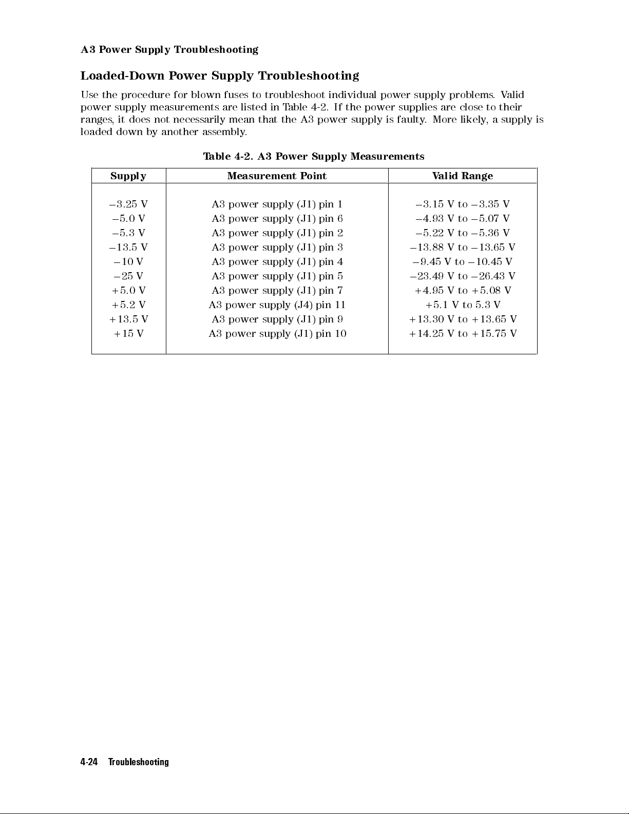
A3 Power Supply Troubleshooting
Loaded-Down Power Supply Troubleshooting
Use the procedure for blown fuses to troubleshoot individual power supply problems.Valid
power supply measurements are listed in Table 4-2. If the power supplies are close to their
ranges, it does not necessarily mean that the A3 power supply is faulty. More likely, a supply is
loaded down by another assembly.
Table 4-2. A3 Power Supply Measurements
Supply Measurement Point Valid Range
0
3.25 V A3 power supply (J1) pin 1
0
5.0 V A3 power supply (J1) pin 6
0
5.3 V A3 power supply (J1) pin 2
0
13.5 V A3 power supply (J1) pin 3
0
10 V A3 power supply (J1) pin 4
0
25 V A3 power supply (J1) pin 5
0
3.15 V to03.35 V
0
4.93 V to05.07 V
0
5.22 V to05.36 V
0
13.88 V to013.65 V
0
9.45 V to010.45 V
0
23.49 V to026.43 V
+5.0 V A3 power supply (J1) pin 7 +4.95 V to +5.08 V
+5.2 V A3 power supply (J4) pin 11 +5.1 V to 5.3 V
+13.5 V A3 power supply (J1) pin 9 +13.30 V to +13.65 V
+15 V A3 power supply (J1) pin 10 +14.25 V to +15.75 V
4-24 Troubleshooting
A4 Idler Phase-Lock Loop Troubleshooting
A4 Idler Phase-Lock Loop Troubleshooting
Idler Unlock
If an FFS unlock is reported along with an idler unlock, repair the FFS unlock before
performing this procedure.
1. Connect an HP 8566B spectrum analyzer to A6A3 idler buer (J3) idler buer out. Complete
\The State Worksheet", and then verify the power output under the following conditions:
Condition Power
IDLER is low
IDLER is high
:::::: ::::::: ::::::: :::::: ::::::: ::::::: ::::::::::::: ::::::: ::::015 to017 dBm
:::::: :::::: ::::::: ::::::: :::::: ::::::: :::::::::::::: :::::: ::::015 to016 dBm
If the power measured in step 1 is incorrect, connect an HP 8566B spectrum analyzer to
A4A3 idler VCO microcircuit (J2) idler PLL output. Verify the power output under the
following conditions:
Condition Power
IDLER is low
IDLER is high
:::::: ::::::: ::::::: :::::: ::::::: ::::::: ::
::::::: :::::: ::::::: ::::::: :::::: ::::::: :::
4to014 dBm (harmonics<0
0to010 dBm (harmonics<0
11 dBc)
9 dBm)
0
If the power or harmonics measured in step 2 are incorrect, refer to \A4 Idler Phase-Lock
Loop Troubleshooting".
If the power and harmonics levels are correct, check the power supplies going to A6A3 idler
buer (J2) at A11 wiring harness (P7). (A11 wiring harness (P7) is the A11 wiring harness
jack connected to A6A3 idler buer (J2).)
A11 wiring harness Power Supply
0
A11 wiring harness (P7) pin 1 (8 wire from A6A2 YTO lock)
A11 wiring harness (P7) pin 4 (91 wire from A3 power supply)
:::::: ::::::: :::::::
:::::: ::::::: :::
If the voltages measured in step 3 are correct, replace the A6A3 idler buer
.
5to012 V
+5 V60.2 V
If the power or harmonics in step 2 are incorrect and the A4A2 idler lock procedure reveals
no problem on the A4A2 idler lock, replace the A4A3 idler VCO microcircuit.
Frequency Error
1. Connect an HP 8566B spectrum analyzer to A7A1 FFS phase lock loop (J1) FFS VCO output.
a. Complete \The State Worksheet".
b. Verify that the FFS START and FFS STOP frequencies match the results on the
worksheet.
c. Measure the output power.
If the power is greater than 0 dBm, refer to \A7 FRAC'N Synthesizer Troubleshooting".
If the frequencies and power at A7A1 FFS phase lock loop (J1) are correct, refer to \A4
Idler Phase-Lock Loop Troubleshooting".
2. If the A4A2 idler lock is working properly:
a. Connect an HP 8566B spectrum analyzer to A4A3 idler V
CO microcircuit (J2).
b. Connect a DVM to A4A2 idler lock (J3).
Troubleshooting 4-25
A4 Idler Phase-Lock Loop Troubleshooting
c. Remove the cable from A4A2 idler lock (J2). The voltage should measure more negative
than023 V.
3. If the voltage is incorrect, replace the A4A2 idler lock. The signal on the HP 8566B
spectrum analyzer should measure within the following frequency ranges:
Condition Frequency
IDLER is low
IDLER is high
:::::: ::::::: ::::::: ::::::: :::::: ::::::: ::::::::::::: ::::::: ::::::: :::>
:::::: :::::: ::::::: ::::::: ::::::: :::::: :::::::::::::: :::::: ::::::: :::>
3585 MHz
5385 MHz
4. Reconnect the cable to A4A2 idler lock (J2), then remove the RF cable from A4A1 300 MHz
amplier (J1). The voltage at A4A2 idler lock (J3) should measure more positive than02V.
If the voltage is incorrect, replace the A4A2 idler lock. The signal on the HP 8566B
spectrum analyzer should be within the following frequency ranges:
Condition Frequency
IDLER is low
IDLER is high
5. If the frequencies measured in steps 3 and 4 are incorrect, replace the A4A3 idler V
:::::: ::::::: ::::::: ::::::: :::::: ::::::: ::::::::::::: ::::::: ::::::: :::<
:::::: :::::: ::::::: ::::::: ::::::: :::::: :::::::::::::: :::::: ::::::: :::<
3510 MHz
5310 MHz
CO
microcircuit. If the frequencies are correct, reconnect the RF cable to A4A1 300 MHz
amplier (J1).
6.
Press
4
MENU
NNNNNNNNNNNNNNNNNNNNNNN
5
BW, Swp
7. If the voltage at A4A2 idler lock (TP2) is between
NNNNNNNNNNNNNNNNNNNNNNNNNNNNNNNNNNNNNN
SINGLE SWEEP
to initiate a sweep.
0
3 V and021 V and the HP 70900B local
oscillator source front panel IDL LED is on:
a. Measure the voltage at A1A1 host/processor (TP3) LIDLK.
b. If the voltage is a TTL high, troubleshoot the A4A2 idler lock.
c. If the voltage measured is a TTL low
, measure the voltage at A1 (J6) pin 41 on the A1A1
host/processor.
d. If the voltage is a TTL low, the A1A1 host/processor or A1A2 1/4 MB RAM/ROM is faulty
e. If the voltage is a TTL high, follow the LIDLK line through the A10 motherboard to the
A8 frequency control to see where the LIDLK changes state
.
.
8. Connect an HP 8566B spectrum analyzer to A4A2 idler lock (TP1) using a 1:1 probe and a
DC-blocking capacitor.
a. Check for a signal between 5 MHz and 130 MHz with an amplitude greater than
0
55 dBm.
If the signal meets these specications, the A4A2 idler lock is faulty.
If the signal falls out of the frequency range or has low amplitude
, change the A4A3 idler
VCO microcircuit.
A4A1 300 MHz Amplier Troubleshooting
1. Test the A6A1 100 MHz reference (J1) connection:
a. Connect an HP 436A power meter with an HP 8482A N(m) power sensor to A6A1 100
MHz reference (J1) 300 MHz out.
b. Verify that the power is greater than 0 dBm.
c. Connect an HP 8566B spectrum analyzer to A6A1 100 MHz reference (J1).
If the harmonics are025 dBc or greater, refer to \A6 YTO Phase-Lock Loop/A8
Frequency Control Troubleshooting".
4-26 Troubleshooting
A4 Idler Phase-Lock Loop Troubleshooting
If the harmonics at A6A1 100 MHz reference (J1) are less than025 dBc:, reconnect the
cable to A6A1 100 MHz reference (J1).
2. Test the CALIBRATOR connection:
a. Connect the power meter to the local oscillator source's front panel CALIBRATOR.
b. Verify that the power is010 dBm,60.3 dB.
If the power is incorrect, adjust or replace the A4A1 300 MHz amplier.
3. Test the rear panel 300 MHz #1 jack:
a. Connect the power meter to the local oscillator source's rear panel 300 MHz 1 jack.
b. Verify that the power is 0 dBm,61dB.
If the power out is incorrect, rst perform \Adjustment 05. Calibrator Output
Amplitude" in Chapter 6, then perform \Adjustment 06. 300 MHz Reference Output
Amplitude" in Chapter 6 as described in Chapter 6.
c. Connect the spectrum analyzer to the jack and measure the harmonics.
If the harmonics are030 dBc or greater, replace the A4A1 300 MHz amplier.
4. Repeat this procedure for the rear panel 300 MHz #2 jack.
5. Measure the voltage at A4A1 300 MHz amplier (J2) pin 1 (300 MHz post-lter detector).
If the voltage is less than or equal to +0.2 V
6. Measure the voltage at A4A1 300 MHz amplier (J2) pin 2 (A
If the voltage is greater than or equal to +1.2 V
Note
Component-level repairs should not be attempted on the M block of the
, replace the A4A1 300 MHz amplier.
GC voltage).
, replace the A4A1 300 MHz amplier.
schematic for A4A1 300 MHz amplier. This circuit (doubler 300 MHz to 600
MHz), has components that must be factory adjusted. The A4A1 300 MHz
amplier should be replaced if this circuit is suspect.
7. Measure the voltage at A4A1 300 MHz amplier (J6) pin 3 600 MHz detector
If the voltage is less than or equal to +1.1 V
, replace the A4A1 300 MHz amplier.
.
A4A2 Idler Lock Troubleshooting
1. Remove the A7 FRAC'N synthesizer and install it on extender cables.
2. Remove the A4A2 idler lock's cover.
3. To determine if the IDLER STATE is high or low, refer to \The State Worksheet".
4. Measure the voltage at A4A2 idler lock (J1) pin 3.
If the IDLER STATE is low, the voltage should be a TTL high.
If the IDLER STATE is high, the voltage should be a TTL low.
5. Measure the voltage at A4A2 idler lock (J4).
If the IDLER STATE is low, the voltage should be from03.5 V to09V.
0
If the IDLER STATE is high, the voltage should be from
0.5 V to +0.5 V.
6. If the voltage is incorrect, troubleshoot the A4A2 idler lock.
Troubleshooting 4-27
A4 Idler Phase-Lock Loop Troubleshooting
7. Measure the voltage at A4A2 idler lock (J5). For ambient temperatures (20Cto30C),
the voltage should be +12.0 V60.6 V.
If the voltage is incorrect, troubleshoot the A4A2 idler lock.
8. Measure the voltage at A4A2 idler lock (J6). If the IDLER STATE is low, the voltage should
be from00.5 V to +0.5 V. If the IDLER STATE is high, the voltage should be from07.5 V
to09V.
If the voltage is incorrect, troubleshoot the A4A2 idler lock.
9. Measure the voltage at A4A2 idler lock (J8). The voltage should be from +4 V to +5.1 V.
If the voltage is incorrect, troubleshoot the A4A2 idler lock.
10. Measure the voltage at A4A2 idler lock (J9). The voltage should be from09.0 V to010.1
V.
If the voltage is incorrect, troubleshoot the A4A2 idler lock.
Spurious/Sideband/Noise
In the following instructions assume that the frequency and power at the rear panel 300 MHz
outputs and at A4A3 idler VCO microcircuit (J2) (A4 idler phase-lock loop output) are correct.
If the rear panel 300 MHz signals are incorrect, refer to \A4 Idler Phase-Lock Loop
Troubleshooting".
If the A4 idler phase-lock loop output is incorrect, refer to \Idler Unlock" and \Frequency
Error" under \A4 Idler Phase-Lock Loop Troubleshooting".
Use this procedure to troubleshoot spurious signals, sidebands, or noise. This section applies if:
Spurious signals, sidebands, or high-noise conditions are found on the rear panel LO output
and at A4A3 idler VCO microcircuit (J2) A4 Idler Phase-Lock Loop output but not at A1 (J1)
FFS PLL output.
Spurious signals, sidebands, or noise conditions are found on the rear panel 300 MHz outputs
A4A1 300 MHz amplier (J4-J5) but not at A6A1 100 MHz reference (J1) A6A1 100 MHz
reference 300 MHz output.
1. If spurious, sidebands, or noise are on the A4 idler phase-lock loop output, perform steps 1a
and 1b.
a. Connect an HP 8566B spectrum analyzer to A4A3 idler VCO microcircuit (J2) A4 idler
phase-lock loop output. Spurious signals should be less than071 dBc for osets below
15 kHz. Spurs beyond the 15 kHz oset fall outside the YTO lock loop's bandwidth and
should be less than060 dBc.
If the spurs do not meet these specications, connect the spectrum analyzer to A1 (J1)
FFS PLL output.
If the spurs are on the FFS signal, refer to \A7 FRAC'N Synthesizer Troubleshooting".
b. The phase noise at A4A3 idler VCO microcircuit (J2) should be less than091 dBc at a 1
kHz oset (measured in a 1 Hz resolution bandwidth). If the phase-noise is not within
the this limit, connect the spectrum analyzer to the output of the A1 (J1) FFS PLL. The
phase noise should be less than094 dBc at a 1 kHz oset (measured in a 1 Hz resolution
bandwidth).
If the phase noise is not within the limit, refer to \A7 FRA
Troubleshooting".
4-28 Troubleshooting
C'N Synthesizer
A4 Idler Phase-Lock Loop Troubleshooting
Note
Phase noise measurements made with an HP 8566B spectrum analyzer are
based on the spectrum analyzer's typical noise performance rather than its
specied noise performance.
2. If spurious signals, sidebands, or noise are on the rear panel 300 MHz outputs and on the A4
Idler Phase-Lock Loop output (but not on the FFS PLL output), perform steps 2a and 2b.
a. Connect an HP 8566B spectrum analyzer's RF input, through a 300 MHz up-converter
to A4A1 300 MHz amplier (J5). (Refer to the end of Chapter 7 for information on
constructing the up-converter.)
b. Measure the phase noise at A4A1 300 MHz amplier (J5). The spurs should be less than
0
69 dBc and phase noise less than091 dBc (1 Hz) at a 1 kHz oset.
c. If the phase noise and spurs measure within these limits, continue with step 5.
d. If the limits are not met, connect A6A1 100 MHz reference (J1) (300 MHz out) to the
up-converter.
If the spur and noise performance still do not meet the limits, replace the A6A1 100
MHz reference.
If the specications are met, change or troubleshoot the following assemblies in the
order listed:
A4A3 idler VCO microcircuit
A4A2 idler lock
A4A1 300 MHz amplier
Note
The069 dBc spur limit out of the 300 MHz up-converter is not an HP 70900B
local oscillator source performance specication; it is an indication of
performance. A spur at this level would produce a spur on the high idler (worst
case) at about071 dBc.
3. The idler PLL produces output in two frequency ranges
, low and high. The range in use
depends on the LO frequency selected. The preceding steps checked for spurs in the idler
range used at that time. The following steps change the LO frequency so that the idler
output is switched to the frequency range not yet inspected. You can then check for spurs
in this range. If the spurs are not found in this frequency range, replace the A4A3 idler VCO
microcircuit.
4. Connect an HP 8566B spectrum analyzer to A4A3 idler VCO microcircuit (J2) and conrm
that spurs are present on the idler PLL output. (The HP 70000 Series modular spectrum
analyzer system must be in zero span.)
5. Press the following keys on the HP 70000 modular spectrum analyzer:
4
MENU
NNNNNNNNNNNNNNNNN
5
State
NNNNNNNNNNNNNN
More
NNNNNNNNNNNNNN
More
NNNNNNNNNNNNNNNNNNNNNNNNNNNNNNNNNNN
Show states
.
Write down the LOSTART frequency. (LOSTART should equal LOSTOP.) The idler PLL output
changes its frequency range when the LO frequency passes through 4.4375 GHz:
LO Frequency Idler Frequency Range
4.4375 GHz
4.4375 GHz
:::::: ::::::: ::::::: :::::: ::::::: ::::::: ::::::::::::: :::
::::::: ::::::: :::::: ::::::: ::::::: :::::: :::::::::::::: :::
low (3.530 to 3.565 GHz)
high (5.330 to 5.365 GHz)
Troubleshooting 4-29
A4 Idler Phase-Lock Loop Troubleshooting
6. A change in the analyzer's center frequency produces an equal change in the analyzer's LO
and idler PLL frequencies.To change the idler PLL frequency range, press
then change the center frequency of the analyzer according to the following rules:
a. Change the center frequency by the amount needed for the LO frequency to pass
through the 4.4375 GHz point. For example, if the LO frequency is 5.0 GHz, decrease the
analyzer's center frequency more than 625 MHz. (5.0 GHz04.375 GHz = 0.625 MHz)
b. The change in center frequency must be a multiple of 25 MHz. This ensures that the FFS
PLL output frequency will not change. In the example in step a, the analyzer frequency
could be decreased by 650 MHz.
7. Locate the idler PLL output signal on the HP 8566B spectrum analyzer.
If no spurs are present, change the A4A3 idler VCO microcircuit.
If the spurs are present in both the low and high frequency ranges, the most likely causes
are the A4A2 idler lock or the A4A3 idler VCO microcircuit, (in that order).
NNNNNNNNNNNNNN
Freq
NNNNNNNNNNNNNNNNNNNN
Center
,
4-30 Troubleshooting
A6 YTO Phase-Lock Loop/A8 Frequency Control Troubleshooting
A6 YTO Phase-Lock Loop/A8 Frequency Control
Troubleshooting
YTO Unlock
The following measurement criteria are for functional values and are not intended as test
limits.Test limits are veried by HP Module Verication Software
Note
Any idler unlock or FFS unlock should be repaired before troubleshooting the
A6 YTO phase-lock loop/A8 frequency control.
NNNNNNNNNNNNNNNNNNNNNNNNNNNNNNNNNNNNNNNNN
Make sure
analyzer-test routine, press
Analyzer Test
has been run before starting this procedure.To perform the
4
MENU
NNNNNNNNNNNNNN
5
misc
NNNNNNNNNNNNNN
MORE
NNNNNNNNNNNNNNNNNNNNNNN
SERVICE
NNNNNNNNNNNNNNNNNNNNNNNNNNNNNNNNNNNNNNNNN
ANALYZER TEST
on the system
display. Always wait at least 30 seconds after power-up before performing the test.
NNNNNNNNNNNNNNNNNNNNNNNNNNNNNNNNNNNNNNNNN
Analyzer Test
checks the presence of key reference signals, the ability of the three
phase-lock loops to lock at their maximum and minimum points, the linearity of all
digital-to-analog converters (DACs), and analog-to-digital converter (ADC) performance
.
If any errors other than YTO unlocks 7012, 7013, 7016, or 7028 are reported, refer to the
HP 70000 Modular Spectrum Analyzer Installation and Verication Manual
1. Conrm that correct voltage levels are supplied to A6A1 100 MHz reference
.
, A6A2 YTO
lock, A6A3 idler buer, and A6A4 YTO lock microcircuit on the A11 wiring harness wiring
harness connectors.
2. The voltage at A6A1 100 MHz reference (J5) pin 1 should measure from 0.65 V to 0.85 V
This is the 12.5 MHz detector voltage (the 12.5 MHz signal is the YTO PLL's reference).
3. The voltage at A6A1 100 MHz reference (J7) pin 2 should measure from 0.65 V to 0.85 V
This is the 125 kHz detector voltage (the 125 kHz signal is the FFS PLL's reference).
4. The voltage at A6A1 100 MHz reference (J7) pin 3 should measure from 0.5 V to 2.1 V
is the 50 MHz detector voltage (the 50 MHz signal is the sampler bias level).
.
.
. This
5. Tune the analyzer to the settings that cause a YTO PLL unlock and ll in \The State
Worksheet".
6. Measure the A6 YTO phase-lock loop/A8 frequency control output power at the rear panel
LO jack (A6A4 YTO lock microcircuit (J3)). The power should be5 dBm but less than
12 dBm . If the power is not within this range, measure the power out of the A6A5 YTO.
The power should be 11 dBm63dB.
If the power is incorrect, replace the A6A5 YTO
.
If the power is correct, run \Adjustment 18. YTO Frequency Endpoints" in Chapter 6.
7. If the unlock condition still exists, with the analyzer in zero span, measure the power and
frequency of the Idler PLL signal supplied to A6A4 YTO lock microcircuit (J1).
a. Disconnect A6 YTO phase-lock loop (W18) at A6A4 YTO lock microcircuit (J1).
b. Measure the signal out of A6 YTO phase-lock loop (W18).
The correct idler frequency is calculated on \The State Worksheet", lled out at the start
of this procedure. The power should be within the limits below
.
Idler State Idler PLL Output Power to A6A4 YTO lock microcircuit (J1)
0
Low
:::::: ::::::: ::::::: :::::: ::::::: ::::::: ::::::::::::: ::::::: :::::: ::::::
15 to017 dBm
Troubleshooting 4-31

A6 YTO Phase-Lock Loop/A8 Frequency Control Troubleshooting
High
:::::: ::::::: :::::: ::::::: ::::::: :::::: :::::::::::::: :::::: ::::::: ::::::015 to016 dBm
If the power or frequency values are not correct, refer to \A4 Idler Phase-Lock Loop
Troubleshooting".
8. Reconnect A6 YTO phase-lock loop (W18). Monitor A6A2 YTO lock (TP1) with an
oscilloscope and a 10:1 probe. When the YTO is locked, there should be a 12.5 MHz
rectangular waveform of about 0.8 Vp-p (ECL levels through a capacitor). When the YTO is
unlocked, the waveform frequency will be in the 0 to 25 MHz range.
9. If the waveform at A6A2 YTO lock (TP1) has rounded edges:
a. Write down the spectrum analyzer's span and sweep-time settings.
b. Set the spectrum analyzer to a 1 GHz span with a sweep time of 20 seconds.
c. Initiate a sweep on the spectrum analyzer.
10. After the sweep is initiated, the waveform at A6A2 YTO lock (TP1) should be rectangular,
sweeping from 0 to 25 MHz.
If the waveform is still rounded or missing, place the A8 frequency control on extender
cables and remove the A6A2 YTO lock casting cover. (This does not require removing the
entire A6 YTO phase-lock loop.)
11. Use an HP 8566B spectrum analyzer and a 1:1 probe with a DC-blocking capacitor to check
0
A6A2 YTO lock (J1-1) for a signal level between
22 dBm and030 dBm, from 0 to 25 MHz.
If the signal is missing or low, check the voltages supplied to the A6A4 YTO lock
microcircuit.
If the voltages measure correctly, replace A6A4 YTO lock microcircuit.
0
If the signal at A6A2 YTO lock (J1-1) is greater than
22 dBm and the waveform is still
rounded, replace the A6A2 YTO lock.
12. Connect an oscilloscope with a 10:1 probe to A6A2 YTO lock (U3) pin 11. Conrm that a
12.5 MHz ECL rectangular wave is present.
If no signal is found, refer to \A6 YTO Phase-Lock Loop/A8 Frequency Control
Troubleshooting".
13. Set the HP 70000 Series modular spectrum analyzer system to a 100 Hz span. Use an SMB
snap-on tee to connect a digital voltmeter (DVM) between A6A2 YTO lock (J6) and (W4).
Connect an oscilloscope to A6A2 YTO lock (J5) pin 8. Refer to the \The State W
orksheet",
for the lock polarity value.
14. Find the values of A6A2 YTO lock (J5) pin 8 and the lock polarity in the following table
follow the instructions in the \Action/Status" column.
YTO PLL State
TTL Logic at
Lock Polarity Action/Status
A6A2 YTO lock (J5) pin 8
TTL High POS Functioning properly
TTL Low NEG Functioning properly
TTL Low POS Replace A8 frequency control
TTL High NEG Replace A8 frequency control
15. Remove the cable to A6A2 YTO lock (J4) and observe the voltage at A6A2 YTO lock (J6).
Find the values of A6A2 YTO lock (J5) pin 8, A6A2 YTO lock (J6), and the lock polarity in
the following table, then follow the instructions in the \A
ction/Status" column.
4-32 Troubleshooting
A6 YTO Phase-Lock Loop/A8 Frequency Control Troubleshooting
YTO PLL State (W19 Removed)
TTL Logic at
Lock Polarity Voltage at A6A2 YTO lock (J6) Action/Status
A6A2 YTO lock (J5) pin 8
TTL High NEG or POS +9 V Functioning properly
TTL High POS
TTL Low NEG or POS
TTL Low NEG
<
+9 V* Replace A6A2 YTO lock
<09V* Functioning properly
>09V
y
Replace A6A2 YTO lock
*<indicates \more negative than"
y>indicates \more positive than"
16. Replace the cable to A6A2 YTO lock (J4). Remove the power supply connector on top of
A6A4 YTO lock microcircuit and observe the voltage at A6A2 YTO lock (J6). Find the
values of A6A2 YTO lock (J5) pin 8, A6A2 YTO lock (J6), and the lock polarity in the
following table, then follow the instructions in the \Action/Status" column.
YTO PLL State (Power Removed)
TTL Logic at
Lock Polarity Voltage at A6A2 YTO lock (J6) Action/Status
A6A2 YTO lock (J5) pin 8
TTL High NEG or POS
TTL High POS
TTL Low NEG or POS
TTL Low NEG
<09V* Functioning properly
>09V
>
<
+9 V
y
y
Replace A6A2 YTO lock
Functioning properly
+9 V* Replace A6A2 YTO lock
*<indicates \more negative than"
y>indicates \more positive than"
17. Replace the power supply connector on top of A6A4 YTO lock microcircuit. Install the
connector with the red wire toward the rear panel. Initiate an analyzer sweep
0
If the voltage at A6A2 YTO lock (J6) is between
UNLOCKED
is still displayed, check A6A2 YTO lock (J5) pin 6 for a TTL low.
8 V and +8 V and the message
.
YTO IS
If A6A2 YTO lock (J5) pin 6 is not TTL low, replace the A6A2 YTO lock.
18. Connect an HP 3325B synthesized function/sweep generator to A8 frequency control (J1).
Set the function generator for a09 V to +9 V sine wave of 1 kHz.
19. Connect an HP 8566B spectrum analyzer to the rear panel LO jack (A6A4 YTO lock
microcircuit (J3)).
If the signal excursion is between 30 to 45 MHz, the A6 YTO phase-lock loop/A8
frequency control is probably functioning properly.
If the signal excursion at A6A4 YTO lock microcircuit (J3) is outside this range, connect
an oscilloscope to A8 frequency control (TP4-4).
20. The signal at A8 frequency control (TP4-4) should be a09 V to +9 V,60.5 V sine wave.
If the sine wave is not present, replace A8 frequency control.
If it is present but the signal excursion is incorrect, change the A6A5 YTO
.
21. Change the function generator frequency to 20 Hz.
If the signal excursion on the HP 8566B spectrum analyzer is not between 30 and 45
MHz, replace the A8 frequency control.
Troubleshooting 4-33

A6 YTO Phase-Lock Loop/A8 Frequency Control Troubleshooting
A6A1 100 MHz Reference Troubleshooting
NNNNNNNNNNNNNNNNNNNNNNNNNNNNNNNNNNNNNNNNN
Fill out \The State Worksheet" and make sure
this procedure.To perform the analyzer-test routine, press
NNNNNNNNNNNNNNNNNNNNNNNNNNNNNNNNNNNNNNNNN
ANALYZER TEST
on the system display. Always wait at least 30 seconds after power-up before
Analyzer Test
4
MENU
has been run before starting
NNNNNNNNNNNNNN
5
NNNNNNNNNNNNNN
misc
MORE
NNNNNNNNNNNNNNNNNNNNNNN
SERVICE
performing the test.
NNNNNNNNNNNNNNNNNNNNNNNNNNNNNNNNNNNNNNNNN
Analyzer Test
checks the presence of key reference signals, the ability of the three
phase-lock loops to lock at their maximum and minimum points, the linearity of all
digital-to-analog converters (DACs), and analog-to-digital converter (ADC) performance.
If any errors other than YTO unlocks 7012, 7013, 7016, or 7028 are reported, refer to the
HP 70000 Modular Spectrum Analyzer Installation and Verication Manual
.
1. Set an HP 8566B spectrum analyzer to the following settings:
Center Frequency
Span
:::::: ::::::: :::::: ::::::: ::::::: :::::: :::::::::::::: :::::: ::::::: ::::::: :::: ::::::
Resolution BW
:::::: ::::::: :::::: ::::::: ::::::: :::::: :::::::::::::: :::::: :::::::
100 MHz
::::: ::::::: ::::::: ::::::: :::::: ::::::: ::::::::::::: ::::::: ::::::: ::::::
1 MHz
10 kHz
2. Connect the HP 8566B spectrum analyzer to A6A1 100 MHz reference (J1). If the signal
measures less than02 dBm, perform \Adjustment 03. 300 MHz Bandpass Filter" in
Chapter 6. After performing this adjustment, the signal at A6A1 100 MHz reference (J1)
should be greater than02 dBm. If the power is still low
, check \The State Worksheet" for
the value of REF.
If REF is INTERNAL, perform step 2a.
If REF is EXTERNAL and no external reference is applied, perform step 2b
.
a. Connect a DVM to A6A1 100 MHz reference (J3) pin 5.
If the voltage at A6A1 100 MHz reference (J3) pin 5 is a TTL high, replace the A6A1
100 MHz reference.
If the voltage at A6A1 100 MHz reference (J3) pin 5 is other than a TTL high, change
the A8 frequency control.
b. Check A6A1 100 MHz reference (J3) pin 2 with a DVM.
If the voltage is greater than +25 mV, replace the A6A1 100 MHz reference.
If it is less than or equal to +25 mV
, replace the A2 video processor.
3. Connect an HP 8663A synthesized signal generator to A6A1 100 MHz reference (J2). Set
the generator to 100 MHz at 0 dBm.
4. Set the HP 70000 Series modular spectrum analyzer system to continuous-sweep mode.
If the analyzer's extended state shows internal reference, measure A6A1 100 MHz
reference (J3) pin 2 with a DVM.
If the voltage at pin 2 measures less than or equal to +50 mV, replace the A2 video
processor.
If the voltage at A6A1 100 MHz reference (J3) pin 3 is less than +50 mV, replace the
A6A1 100 MHz reference.
5. Connect an oscilloscope with a 10:1 probe to A6A1 100 MHz reference (J4). Check for an
emitter-coupled logic (ECL) signal at 12.5 MHz.
If a signal of approximately 0.8 Vpp is not present, change the A6A1 100 MHz reference.
6. Tune the HP 70000 Series modular spectrum analyzer system to a center frequency of 300
MHz and a span of 1 MHz.
7. Use an HP 5316B universal counter to verify that a 125.00 kHz pulse is present at A6A1
100 MHz reference (J6).
4-34 Troubleshooting

A6 YTO Phase-Lock Loop/A8 Frequency Control Troubleshooting
If no pulse is found, check A6A1 100 MHz reference (J7) pin 4 with a DVM.
If the voltage at A6A4 YTO lock microcircuit (J7) measures05V, change the A6A1 100
MHz reference.
If it measures 0 V, change the A8 frequency control.
8. Tune the spectrum analyzer to a center frequency of 300 MHz and a span of 100 Hz.
9. Use the universal counter to verify that a 124.84 kHz signal is present at A6A1 100 MHz
reference (J6).
If no signal is found, check A6A1 100 MHz reference (J7) pin 4 with a DVM.
If the DVM measures 0 V, change the A6A1 100 MHz reference.
If it measures05V, change the A8 frequency control.
10. Check A6A1 100 MHz reference (J8):
a. Place the A1, A3 power supply, and A8 frequency control on extenders.
b. Remove semirigid cable W17 (A4A3 idler VCO microcircuit (J2) to A6A3 idler buer
(J1)).
c. Unsnap semirigid cable A6 YTO phase-lock loop (W16) (A6A5 YTO to AT1) from the clips
on the A10 motherboard.
d. Remove the four screws securing the A6 YTO phase-lock loop to the
local oscillator source's frame.
e. Remove the A6A1 100 MHz reference cover.
f. Connect an oscilloscope with a 10:1 probe to A6A1 100 MHz reference (J8).
If a 50 MHz waveform is not present, change the A6A1 100 MHz reference
.
Spurious/Sideband
All spurious signals and sidebands are referred to as spurs in this procedure
. The
troubleshooting procedure is the same for both. This procedure applies to HP 70900B local
oscillator sources that have spurs on A6A1 100 MHz reference (J1) (300 MHz output) or spurs
on the rear panel LO output, but not on A6A3 idler buer (J3) idler buer output.
1. Complete \The State Worksheet" to determine key frequencies and switch positions at the
settings where the spurs occur.
If the power or frequency of the rear panel LO output jack is incorrect, refer to \YTO
Unlock" under \A6 YTO Phase-Lock Loop/A8 Frequency Control Troubleshooting".
If the power or frequency of the front panel CALIBRATOR jack or rear panel 300 MHz
jacks is incorrect, refer to A6A1 100 MHz reference.
2. Connect an HP 8566B spectrum analyzer to the local oscillator source 's rear panel LO
output jack (A6A4 YTO lock microcircuit (J3)). Refer to \External Frequency Reference
Chapter 8 to lock the local oscillator source's reference to the HP 8566B spectrum analyzer
3. Initiate a sweep on the HP 70000A modular spectrum analyzer to enable the external
reference.
4. If the spurs disappear, the internal reference is causing the spurs. Replace the A6A1 100
MHz reference. Leave the external reference connected.
5. If the spurs are not caused by the internal reference and occur in osets less than 1 kHz,
place the HP 70900B local oscillator source on an HP 70001-60013 extender module.
"in
.
If no spurs are present or if they are greatly reduced in amplitude, replace the A8
frequency control.
6. Perform \LO Output Spurious Response Test" in Chapter 7.
If the test fails, perform \Adjustment 14. FFS Spurious Responses" in Chapter 6.
Troubleshooting 4-35

A6 YTO Phase-Lock Loop/A8 Frequency Control Troubleshooting
If the spurs at A6A4 YTO lock microcircuit (J3) are 24 kHz sidebands, replace the A6A5
YTO or A8 frequency control.
If the spurs are 40 kHz sidebands, connect the HP 8566B spectrum analyzer to the idler
output (A4A3 idler VCO microcircuit (J2)).
If 40 kHz spurs of similar amplitude are present on the idler output, replace the A3
power supply.
If the sideband amplitude is dierent or if no 40 kHz sideband is found, replace the
A6A5 YTO.
7. All spurs should be less than071 dBc at room temperature.
If the spurs are071 dBc, connect an HP 8566B spectrum analyzer to A6A3 idler buer
(J3) idler buer output.
If the spurs at A6A3 idler buer (J3) are present, refer to \Spurious/Sideband/Noise"
under \A4 Idler Phase-Lock Loop Troubleshooting".
8. If no spurs are present at A6A3 idler buer (J3), connect the HP 8566B spectrum analyzer
to A6A1 100 MHz reference (J4) (12.5 MHz reference output) through a DC-blocking
capacitor.
If the spurs are at A6A1 100 MHz reference (J4), replace the A6A1 100 MHz reference
9. If spurs are not found:
a. Connect A6A1 100 MHz reference (J1) 300 MHz reference output to the input of the 300
MHz up-converter.
b. Connect the output of the up-converter to the input of the HP 8566B spectrum analyzer
(Instructions for assembling the 300 MHz up-converter are included in Chapter 7.)
If the spurs of interest are greater than069 dBc, change the A6A1 100 MHz reference.
10. If no failed assembly has been found, the most probable causes of the spurs are the A6A5
YTO and the A8 frequency control, in that order
.
.
.
4-36 Troubleshooting

A7 FRAC'N Synthesizer Troubleshooting
A7 FRAC'N Synthesizer Troubleshooting
FFS Unlock
NNNNNNNNNNNNNNNNNNNNNNNNNNNNNNNNNNNNNNNNN
Make sure
analyzer-test routine, press
Analyzer Test
has been run before starting this procedure.To perform the
4
MENU
NNNNNNNNNNNNNN
5
misc
NNNNNNNNNNNNNN
MORE
NNNNNNNNNNNNNNNNNNNNNNN
SERVICE
NNNNNNNNNNNNNNNNNNNNNNNNNNNNNNNNNNNNNNNNN
ANALYZER TEST
on the system
display. Always wait at least 30 seconds after power-up before performing the test.
NNNNNNNNNNNNNNNNNNNNNNNNNNNNNNNNNNNNNNNNN
Analyzer Test
checks the presence of key reference signals, the ability of the three
phase-lock loops to lock at their maximum and minimum points, the linearity of all
digital-to-analog converters (DACs), and analog-to-digital converter (ADC) performance.
If any errors other than YTO unlocks 7012, 7013, 7016, or 7028 are reported, refer to the
HP 70000 Modular Spectrum Analyzer Installation and Verication Manual
.
Tune the HP 70000 analyzer to the settings where any A7 FRAC'N synthesizer unlock occurs.
Fill out \The State Worksheet", and troubleshoot the unlock conditions with the following
procedure. If the A7A2 FFS analog was replaced, make sure that the SMB cables were
correctly reconnected.
1. Connect an HP 5316B universal counter to A6A1 100 MHz reference (J6).
If no signal is present, refer to A6A1 100 MHz reference
.
2. Connect a DVM to A6A1 100 MHz reference (J7) pin 4. Measure the frequency at A6A1
100 MHz reference (J6) with the universal counter. The signal should be at ECL levels
(high00.98 V, low01.63 V). Table 4-3 shows the correct voltage and frequency values
for the \divide" number listed on the state worksheet.
If the voltage is incorrect, change the A8 frequency control.
If the voltage is correct but the frequency is not, change A6A1 100 MHz reference
.
Table 4-3.
Measurements at A6A1 100 MHz Reference (J6) and (J7) Pin 4
Divide Number A6A1 100 MHz reference (J7) Pin 4 A6A1 100 MHz reference (J6)
4
800
4
801 0V 124.84 kHz
0
5V 125 kHz
3. Check A7A1 FFS phase lock loop (J1):
a. Connect an HP 8566B spectrum analyzer to A7A1 FFS phase lock loop (J1) (A7 FFS V
output).
b. Connect +10 V from a DC power supply to A7A1 FFS phase lock loop (J3) (FFS V
CO
tune). The signal frequency should be less than 33.5 MHz, with a power level greater
than 0dBm.
CO
c. Connect07 V from a DC power supply to A7A1 FFS phase lock loop (J3). The signal
frequency should be greater than 70 MHz with a power level greater than 0 dBm.
If the power level is low or the frequency extremes cannot be met, change the A7A1 FFS
phase lock loop.
4. Reconnect cable W3:
a. Lay the HP 70900B local oscillator source on its side so the A1A1 host/processor is on the
bottom.
Troubleshooting 4-37
A7 FRAC'N Synthesizer Troubleshooting
b. Remove the three screws securing the A7 FRAC'N synthesizer to the bottom of the
local oscillator source.
c. Remove cable W3 (125 kHz reference) from A7A2 FFS analog (J2).
d. Slide the assembly upward about one-half inch, and pull the end with the LED outward.
e. Rotate the assembly 180 degrees so the top of the assembly is against the top cabling of
the rest of the local oscillator source .
f. Reconnect cable W3 to A7A2 FFS analog (J2).
5. Check the pulse at ECL levels:
a. Connect an HP 3325B synthesized function/sweep generator to the high-impedance input
of an oscilloscope.
b. Set the function generator to a 10 MHz square wave at ECL levels (high00.98 V, low
0
1.63 V).
c. Connect the function generator to A7A1 FFS phase lock loop (J5).
d. Connect a cable from A6A1 100 MHz reference (J6) to A7A1 FFS phase lock loop (J6)
(125 kHz).
e. Connect an oscilloscope to A7A1 FFS phase lock loop (J4).
f. Verify that a pulse at ECL levels is present.
If a pulse is not found or is at a level other than ECL, replace the A7A1 FFS phase lock
loop.
If the pulse is present, replace the cables to the A7A1 FFS phase lock loop
.
6. Check the signal at A7A1 FFS phase lock loop (J7):
a. Remove the cable connected to A7A1 FFS phase lock loop (J3) and place a 50 load on
the jack.
b. Connect an oscilloscope, using the 50 impedance setting, to A7A1 FFS phase lock loop
(J7).
c. Verify that a signal greater than 50 mVpp is present at A7A1 FFS phase lock loop (J7).
If the signal is less than or equal to 50 mVpp, replace the A7A1 FFS phase lock loop.
If the amplitude is above this value, replace the A7A2 FFS analog.
Spurious Signals/Noise
When the A7 FRAC'N synthesizer is the source of spurious signals or noise
, troubleshoot with
the procedure below.
If noise is the problem, connect a spectrum analyzer through a DC-blocking capacitor to
A6A1 100 MHz reference (J7).
If the spurious signal or noise is present on the 124.84/125 kHz signal, replace the A6A1 100
MHz reference.
1. If no spurious signal or noise is found, check if the noise increases when the FFS PLL output
frequency is closer to 70 MHz than when it is near 45 MHz. For every 1 Hz increase in LO
frequency, the FFS PLL output decreases 1 Hz. This process is repeated every 25 MHz.
2. Determine the FFS frequency from \The State W
orksheet", and then tune the LO
accordingly.
4-38 Troubleshooting
A7 FRAC'N Synthesizer Troubleshooting
If the noise does increase, replace the A7A1 FFS phase lock loop.
If the noise occurs in osets greater than 3 kHz, the most probable cause is the A7A1 FFS
phase lock loop.
3. If the noise occurs in osets less than 3 kHz:
a. Connect an HP 8663A synthesized signal generator to the HP 70900B local oscillator
source rear panel 100 MHz input.
b. Set the signal generator to 100 MHz at 0 dBm.
c. Initiate a sweep on the HP 70900B local oscillator source to enable the external
reference.
If the noise is gone, replace the A6A1 100 MHz reference.
If the noise remains, replace the A7A2 FFS analog.
Troubleshooting 4-39
If You Have Verication Test Failures
These troubleshooting suggestions are listed by verication test number. If the
local oscillator source fails a verication test, look up that test in the list and follow the
instructions.
Before troubleshooting, always make sure the failure is not caused by the test equipment.
If a previous repair involved removing assemblies, make sure that the connector pins were not
bent during replacement.
If Test 01. 300 MHz Reference Output Power and Harmonics Fails
To solve this problem:
1. Perform a calibrator output amplitude adjustment (see Chapter 6).
2. Perform a 300 MHz reference output amplitude adjustment (see Chapter 6).
3. Otherwise, troubleshoot the A4A1 300 MHz amplier.
4. If necessary, obtain service from Hewlett-Packard. (Refer to \If You Want Hewlett-Packard
to Service Your Local Oscillator Source " in Chapter 1.)
If Test 02. LO Output Power and Harmonics Fails
To solve this problem:
1. If the power-out test fails, troubleshoot the A6 YTO phase-lock loop.
2. If the harmonics test fails, replace the A6A5 YTO.
3. If necessary, obtain service from Hewlett-Packard. (Refer to \If You Want Hewlett-Packard
to Service Your Local Oscillator Source " in Chapter 1.)
If Test 03. Residual FM (Span>10 MHz) Fails
This test checks the residual FM of the A6A5 YTO and the tuning control of the A8 frequency
control in a non-phase-locked condition.
To solve this problem:
1. Check the A6A5 YTO.
2. Check the A8 frequency control.
3. If necessary, obtain service from Hewlett-Packard. (Refer to \If You Want Hewlett-Packard
to Service Your Local Oscillator Source " in Chapter 1.)
If Test 04. LO Output Spurious Response Fails
To solve this problem:
1. Perform the low-idler adjustment (see Chapter 6).
2. If necessary, obtain service from Hewlett-Packard. (Refer to \If You Want Hewlett-Packard
to Service Your Local Oscillator Source " in Chapter 1.)
4-40 Troubleshooting
If You Have Verication Test Failures
If Test 05. LO Display Sidebands Fails
To solve this problem:
1. Replace the A6A5 YTO.
2. If necessary, obtain service from Hewlett-Packard. (Refer to \If You Want Hewlett-Packard
to Service Your Local Oscillator Source " in Chapter 1.)
If Test 06. LO 40 kHz Sidebands Fails
To solve this problem:
1. Check the A3 power supply and A6 YTO phase-lock loop housing:
a. Remove the A1A1 host/processor and install it on board extender cables.
b. Remove the screws that fasten the A3 power supply to the A6 YTO phase-lock loop
housing.
c. Install the HP 70900B local oscillator source on an HP 70001-60013 extender module.
d. Tune the local oscillator source to the frequency that failed and monitor the sideband
with a spectrum analyzer.
e. Gently pull the A3 power supply away from the A6 YTO phase-lock loop housing.
f. If the sideband amplitude changes more than 2 dB, replace the A3 power supply
.
2. Troubleshoot the A6A5 YTO or the A8 frequency control.
3. If necessary, obtain service from Hewlett-Packard. (Refer to \If You Want Hewlett-Packard
to Service Your Local Oscillator Source " in Chapter 1.)
If Test 07. Reference Oscillator Accuracy Fails
To solve this problem:
1. Perform a calibration output frequency adjustment (see Chapter 6), and retest.
2. Troubleshoot the A6A1 100 MHz reference.
3. If necessary, obtain service from Hewlett-Packard. (Refer to \If You Want Hewlett-Packard
to Service Your Local Oscillator Source " in Chapter 1.)
If Test 08. Calibrator Amplitude Accuracy Fails
To solve this problem:
1. Perform a calibrator output amplitude adjustment (see Chapter 6) and retest.
2. Troubleshoot the A4A1 300 MHz amplier.
3. If necessary, obtain service from Hewlett-Packard. (Refer to \If You Want Hewlett-Packard
to Service Your Local Oscillator Source " in Chapter 1.)
Troubleshooting 4-41
If You Have Verication Test Failures
If Test 09. 300 MHz Reference Amplitude Accuracy Fails
To solve this problem:
1. If this test fails for power only, perform a calibrator output amplitude adjustment, then
perform a 300 MHz reference output amplitude adjustment (see Chapter 6).
2. If the test still fails, or if the harmonics test fails, troubleshoot the A4A1 300 MHz amplier.
3. If necessary, obtain service from Hewlett-Packard. (Refer to \If You Want Hewlett-Packard
to Service Your Local Oscillator Source " in Chapter 1.)
If Test 10. Video Detector Tracking Fails
To solve this problem:
1. Troubleshoot the A2 video processor; make sure it is correctly adjusted.
2. If necessary, obtain service from Hewlett-Packard. (Refer to \If You Want Hewlett-Packard
to Service Your Local Oscillator Source " in Chapter 1.)
If Test 11. External Triggering F
ails
To solve this problem:
1. Check the A1A1 host/processor.
2. If necessary, obtain service from Hewlett-Packard. (Refer to \If You Want Hewlett-Packard
to Service Your Local Oscillator Source " in Chapter 1.)
If Test 12. Video Processor Noise Fails
To solve this problem:
1. Check the A2 video processor.
2. If necessary, obtain service from Hewlett-Packard. (Refer to \If You Want Hewlett-Packard
to Service Your Local Oscillator Source " in Chapter 1.)
If Test 13. LO Frequency and Span Accuracy (Span>10 MHz) Fails
1.
Run the
NNNNNNNNNNNNNNNNNNNNNNNNNNNNNNNNNNNNNNNNN
Analyzer Test
(refer to Figure 4-2).
2. If no errors are reported, perform a frequency control voltage references adjustment, then a
YTO frequency endpoints adjustment (see Chapter 6). Rerun T
est 11. External Triggering.
3. Check the A6A5 YTO.
4. Check the A8 frequency control.
5. If necessary, obtain service from Hewlett-Packard. (Refer to \If You Want Hewlett-Packard
to Service Your Local Oscillator Source " in Chapter 1.)
4-42 Troubleshooting
 Loading...