

Page 1

Agilent 71612 Series of Gb/s Testers
Operating and Programming Manual
SERIAL NUMBERS
This manual applies directly to Agilent 71612 12.5 Gb/s Error Performance Analyzers
comprising the following elements:
Agilent 70843 Option UHF 0.1-12.5 Gb/s Error Performance Analyzer with serial
number(s) prefixed 3xxxU or GBxxxxxxxx.
Agilent 70843 Option UHG 0.1-12.5 Gb/s Pattern Generator with serial number(s)
prefixed 3xxxU or GBxxxxxxxx.
Agilent 70843 Option UHH Error Detector with serial number(s) prefixed 3xxxU or
GBxxxxxxxx.
For additional important information about serial numbers, see SERIAL NUMBER
INFORMATION on page 1-9 in the Operating Manual.
Serial number information for other elements in the system is contained in the following
manuals:
Display see Agilent 70004A Installation and Verification Manual.
Clock Source see Agilent 70340A Operating and Calibration Manual.
© Copyright (2000, 2001, 2002) Agilent Technologies Ltd.
Agilent Part No. 71612-90023
Printed in U.K. July 2002
Page 2

DECLARATION OF CONFORMITY
According to ISO/IEC Guide 22 and CEN/CENELEC EN45014
Manufacturer’s Name: Agilent Technologies UK Limited
Manufacturer’s Address:
Telecomms Networks Test Division
South Queensferry
West Lothian, EH30 9TG
Scotland, United Kingdom
Declares that the product
Product Name
:
Model Number:
Product Options:
0.1-12.5 Gb/s Error Performance Analyzer
70843C
This declaratio n covers a ll options of the above product as deta il ed in
TCF A-5951-9852-01.
EMC:
Conforms with the protection requirements of European Council Directive 89/336/EEC on the approximation of the
laws of the member states relating to electromagnetic compatibility, against EMC test specifications EN 55011:1991
(Group 1, Class A) and EN 50082-1:1992.
As Detailed in: Electromagnetic Compatibility (EMC)
Technical Construction Fi le (TC F) N o. A- 5951-9852-01
Assessed by: DTI Appointed Competent Body
Technical Report Number:6893/220 0/C BR, dated 21 August 1997
EMC Test Centre,
GEC-Marconi Avionics Ltd.,
Maxwell Building,
Donibristle Industrial Park,
Hillend,
Dunfermline
KY11 9LB
Scotland, United Kingdom
Safety:
The product conforms to the following safety standards:
IEC 61010-1(1990) +A1(1 992) +A2(1995) / EN 61010-1:19 93
IEC 60825-1(1993) / EN 60825-1:1994
Canada / CSA-C22.2 No. 1010.1-93
The product herewith complies with the requirements of the Low Voltage Directive 73/23/EEC, and carries the CE
mark accordingly.
South Queensferry, Scotland. 01 June 2001
Robert Tait
Product Regulations Manager
For further information, please contact your local Agilent Technologies sales off ice, agent, or distributor .
Europe Contact:
Your Local Agilent Technologies Sales and Service Office or Agilent Technologies Deutschland GmbH, Herrenberger Strasse 130,
71034 Boeblingen (Fax: +49-7031-143143)
Page 3

DECLARATION OF CONFORMITY
According to ISO/IEC Guide 22 and CEN/CENELEC EN45014
Manufacturer’s Name: Agilent Technologies UK Limited
Manufacturer’s Address:
Telecomms Networks Test Division
South Queensferry
West Lothian, EH30 9TG
Scotland, United Kingdom
Declares that the product
Product Name
:
Model Number:
Product Options:
12.5Gb/s Error Performance Analyz er Syst em
71612C
This declaration covers all options of the above product as detailed in
TCF A-5951-9852-01.
EMC:
Conforms with the protection requirements of European Council Directive 89/336/EEC on the approximation of the
laws of the member states relating to electromagnetic compatibility, against EMC test specifications EN 55011:1991
(Group 1, Class A) and EN 50082-1:1992.
As Detailed in: Electromagnetic Compatibility (EMC)
Technical Construction Fi le (TC F ) No. A- 5951-9852-01
Assessed by: DTI Appointed Competent Body
Technical Report Number:6893/220 0/C BR, dated 21 August 1997
EMC Test Centre,
GEC-Marconi Avionics Ltd.,
Maxwell Building,
Donibristle Industrial Park,
Hillend,
Dunfermline
KY11 9LB
Scotland, United Kingdom
Supplementary Information:
The individual componen ts of th e product meet relevant international saf et y sta ndards.
The product herewith complies with the requirements of the Low Voltage Directive 73/23/EEC, and carries the CE
mark accordingly.
South Queensferry, Scotland. 01 June 2001
Product Regulations Manager
For further information, please contact your local Agilent Te chnologies sales off ice, agent, or distributor .
Robert Tait
Page 4

WARNINGS
The following general safety precautions must be observed during all phases of operation, service, and
repair of this product. Failure to comply with these precautions or with specific warnings elsewhere in this
manual violates safety standards of design, manufacture, and intended use of the product. Agilent Technologies assumes no liability for the customer's failure to comply with these requirements.
This is a safety Class 1 instrument (provided with a protective earthing ground, incorporated in the powercord). The mains plug shall only be inserted in a socket outlet provided with a protective earth contact. Any
interruption of the protective conductor inside or outside of the instrument is likely to make the instrument
dangerous. Intentional interruption is prohibited.
DO NOT operate the product in an explosive atmosphere or in t he presence of flammable gasses or fumes.
For continued protection against fire hazard, replace the line fuses only with the same type and ratings (see
.Fuse Ratings on page 2-10). The use of other fuses or materials is prohibited.
Keep away from live circuits: Operating personnel must not remove equipment covers or shields. Proce-
dures involving the removal of covers and shields are for use by service-trained personnel only. Under certain conditions, dangerous voltages may exist even with the equipment switched off. To avoid dangerous
electrical shock, DO NOT perform procedures involving cover or shield removal unless you are qualified to
do so.
DO NOT operate damaged equipment: Whenever it is possible that the safety protection features built into
this product have been impaired, either through physical damage, excessive moisture, or any other reason,
REMOVE POWER and do not use the product until safe operation can be verified by service-trained personnel. If necessary, return the product to an Agilent Technologies Sales and Service Office for service and
repair to ensure the safety features are maintained.
DO NOT service or adjust alone: Do not attempt internal service or adjustment unless another person, capable of rendering first aid and resuscitation, is present.
DO NOT substitute parts or modify equipment: Because of the danger of introducing additi onal hazards, do
not install substitute parts or perform any unauthorized modification to the product. Return the product to an
Agilent Technologies Sales and Service Office for service and repair to ensure the safety features are maintained.
If this instrument is not used as specified, the protection provided by the equipment could be impaired. This
instrument must be used in a normal condition (in which all means of protection are intact) only.
No operator serviceable parts inside. Refer servicing to qualified personnel. To prevent electrical shock do
not remove covers.
Page 5

CERTIFICATION
Agilent Technologies certifies that this product met its published specifications at the time of shipment from
the factory. Agilent Technologies further certifies that its calibration measurements are traceable to the
United States National Institute of Standards and Technology (formerly National Bureau of Standards), to
the extent allowed by that organization's calibration facility, and to the calibration facilities of other International Standards Organization members.
WARRANTY
This Agilent Technologies product is warranted against detects in materials and workmanshipfor a period of
one year from date of shipment. Duration and conditions of warranty for this product may be superseded
when the product is integrated into (becomes part of) other Agilent products. During the warranty period,
Agilent Technologies will, at its option, either repair or r eplace products which prove to be defective.
For warranty service or repair, this product must he returned to a service facility designated by Agilent Technologies. Buyer shall prepay shipping charges to Agilent and Agilent shall pay shipping charges to return the
product to Buyer. However, Buyer shall pay all shipping charges, duties, and taxes for products returned to
Agilent from another country.
Agilent warrants that its software and f irmware designated by Agilent for use with a product will execute its
programming instructions when properly installed on that product. Agilent does not warrant that the operation of the product or software, or firmware will be uninterrupted or error free.
LIMITATION OF WARRANTY
The foreg oing warranty shall not apply to defects resulting from improper or inadequate maintenance by
Buyer, Buyer-supplied products or interfacing, unauthorized modification or misuse, operation outside of
the environmental specifications for the products, or improper site preparation or maintenance.
The design and implementation of any circuit on this product is the sole responsibility of the Buyer. Agilent
does not warrant the Buyer's circuitry or malfunctions of Agilent products that result from the Buyer's circuitry. In addition, Agilent does not warrant any damage that occurs as a result of the Buyer's circuit or any
other detects that result from Buyer-supplied products.
NO OTHER WARRANTY IS EXPRESSED OR IMPLIED. AGILENT SPECIFICALLY DISCLAIMS
THE IMPLIED WARRANTIES OF MERCHANTABILITY AND FITNESS FOR A PARTICULAR
PURPOSE.
EXCLUSIVE REMEDIES
THE REMEDIES PROVIDED HEREIN ARE BUYER'S SOLE AND EXCLUSIVE REMEDIES.
AGILENT SHALL NOT BE LIABLE FOR ANY DIRECT, INDIRECT, SPECIAL, INCIDENTAL, OR
CONSEQUENTIAL DAMAGES, WHETHER BASED ON CONTRACT, TORT, OR ANY OTHER
LEGAL THEORY.
Page 6

NOTICE
The information contained in this document is subject to change without notice. AGILENT
TECHNOLOGIES MAKES NO WARRANTY OF ANY KIND WITH REGARD TO THIS MATERIAL,
INCLUDING, BUT NOT LIMITED TO, THE IMPLIED WARRANTIES OF MERCHANTABILITYAND
FITNESS FOR A PARTICULAR PURPOSE. Agilent shall not be liable for errors contained herein or for
incidental or consequential damages in connection with the furnishing, performance or use of this material.
This document contains proprietary information which is protected by copyright. All rights are reserved. No
part of this document may he photocopied, reproduced, or translated without the prior written consent of the
Agilent Technologies. Agilent assumes no responsibility for the use or reliability of its software on
equipment that is not furnished by Agilent.
Restricted Rights Legend
Use, duplication or disclosure is subject to restrictions as set forth in subdivision (c)(1)(ii) of the Rights in
Technical Data and Computer Software clause at 52.227-FAR14. Agilent Technologies; 3000 Hanover
Street; Palo Alto, California 94304.
Printing History
The Printing History shown below lists all Editions and Updates of this manual and the printing date(s). The
first printing of the manual is Edition 1. The Edition number increments by 1 whenever the manual is
revised. Updates, which are issued between Editions, contain replacement pages to correct the current Edition of the manual. Updates are numbered sequentially starting with Update 1 . When a new Edition is created, it contains all the Update information for the previous Edition. Each new Edition or Update also
includes a revised copy of this printing history page. Many product updates or revisions do not require manual changes and, conversely, manual corrections may be done without accompanying product changes.
Therefore, do not expect a one-to-one correspondence between product updates and manual updates.
Edition or
Update Date Part Number
Edition 1 Feb 1994 71612-90000 New Edition Mar 2000 71612-90011
Edition 2 Jul 1995 71612.90000 New Edition Mar 2001 71612-90015
New Edition Jun 1998 71612-90007 New Edition July 2001 71612-90016
New Edition Dec 1998 71612-90008 New Edition July 2002 71612-90023
Edition or
Update Date Part Number
Page 7

Agilent 71612 Series of Gb/s Testers
Operating Manual
Page 8

Page 9

Contents - Operating Ma nual
1 General Information
Introduction 1-2
Safety Considerations 1-2
General 1-3
Safety Symbols 1-4
Other Regulatory Markings 1-5
Options 1-6
Introduction 1-6
Upgrade Options 1-8
Accessories Supplied 1-8
Recommended Accessory List 1-8
Serial Number Information 1-9
Returning Instruments for Service 1-9
Packaging Requirements 1-9
Preparing an Instrument for Shipping 1-10
Precautions 1-11
ESD Precautions 1-11
Static-safe Workstation 1-11
Static-safe Accessories 1-12
Lifting/Carrying the Agilent 70843 1-12
Display Cleaning 1-13
Cabinet Cleaning 1-13
How to Update the Agilent 70843 Firmware 1-13
To Update Control Processor Firmware 1-13
To Update Measurement Processor Firmware 1-14
2 Installation
Introduction 2-2
Preparation for Use 2-3
Initial Inspection 2-3
To Fit an Instrument Hardkey Panel 2-3
Statement of Compliance 2-4
Electromagnetic Compatibility (EMC) Information 2-4
Safety Information 2-4
Instruction for cleaning 2-4
Operating Requirements 2-4
Operating and Storage Environment 2-4
Physical Specifications 2-5
Cooling Considerations 2-5
Contents-1
Page 10

Contents - Operating Ma nual
Lifting/Carrying the Agilent 70843 2-6
Power Requirements 2-6
Noise Declaration 2-7
Power Cables 2-7
Line Voltage Selection 2-8
Instrument (Agilent 70843) Line Voltage Selector 2-8
Display (Agilent 70004A) Line Voltage Selector 2-8
Line Fuses 2-9
Accessing the Agilent 70843 Line Fuse 2-9
Accessing the Display (Agilent 70004A) Fuses 2-10
.Fuse Ratings 2-10
HP-MSIB Address Switches 2-10
Factory Preset H P-MSIB Addresses 2-11
Agilent 70843 Address Switches 2-11
Agilent 70340A Clock Source Module Address Switches 2-12
Agilent 70004A Display Address Switches 2-12
GPIB Address Switches 2-12
To Change the GPIB Address 2-13
Factory Preset GPIB Addresses 2-13
Bench Operation 2-13
Rack Mount Installation 2-13
System Installation 2-15
Accessories 2-15
Cables 2-15
Connectors 2-15
Terminations 2-15
Procedure 2-16
System Verification 2-18
Error Performance Analyzer System Verification 2-18
Selftest at Power-on 2-19
Installing/Removing Modules 2-20
Installing an Agilent 70340A Clock Source Module into a Display 2-20
3 System Overview
Configurations 3-2
System Options 3-2
Additional System Options 3-3
Agilent 70843 Instrument Options 3-3
Documentation Overview 3-3
Contents-2
Page 11

Contents - Operating Ma nual
4 Operating F eatures and Specifications
Introduction 4-2
Warm-up 4-2
Operating Temperature Specification 4-2
Calibration Interval 4-2
Pattern Generator 4-3
External connections 4-3
Patterns 4-3
PRBS Test Patterns 4-3
Zero Substitution/Variable Mark Density 4-3
Test Patterns 4-3
Zero Substitution 4-4
Variable Mark Density 4-4
User-programmable test patterns 4-4
Alternate test pattern - pattern generator only 4-4
Internal Disk Drive 4-5
Clock Input 4-5
Features 4-5
Specifications 4-5
Data and Data (inverted) Outputs 4-6
Features 4-6
Data output features not controlled by data output softkeys 4-6
Specifications 4-6
Data outputs - main 4-6
Error Add 4-8
Clock and Clock (inverted) Outputs 4-8
Specifications 4-8
Clock outputs - main 4-8
Subrate Clock & Data (inverted) Outputs 4-9
Features 4-9
Specifications 4-9
Trigger Output 4-9
Features 4-9
Pattern Mode 4-10
PRBS 2^31-1, 2^23-1, 2^15-1, 2^10-1, 2^7-1 4-10
Alternate pattern 4-10
All other patterns 4-10
Divided Clock Mode 4-10
Interface 4-10
Auxiliary Input 4-10
Alternate Pattern Selected 4-11
Data Output Inhibit (Gating mode) 4-11
Contents-3
Page 12

Contents - Operating Ma nual
Interface 4-11
To Select Oneshot Mode 4-11
To Select Alternating Mode 4-11
Error Inject Input 4-12
Interface 4-12
Status Indicators 4-12
Pattern Generator indicators 4-12
Error Detector indicators 4-12
General instrument indicators 4-12
Rear Panel Switches 4-12
Error Detector 4-13
External connections 4-13
Clock Input (error detector) 4-13
Features 4-13
Specifications 4-13
Data Input 4-14
Features 4-14
Specifications 4-14
Pattern Trigger Output (error detector) 4-14
Features 4-15
Pattern Mode 4-15
PRBS 2^31-1, 2^23-1, 2^15-1, 2^10-1, 2^7-1 4-15
All other patterns 4-15
Divided Clock Mode 4-15
Specifications 4-15
Errors Output 4-15
Features 4-15
Interface 4-16
Gating Input 4-16
Interface 4-16
Automatic Clock-to-Data Alignment 4-17
Introduction 4-17
Definition 4-17
Eye Width 4-17
Automatic 0/1 Threshold Center 4-18
To perform a 0/1 Threshold Centering 4-18
Data Input 0/1 Threshold 4-18
Introduction 4-18
Measurements 4-18
Error Analysis 4-19
Power-loss Seconds 4-19
Sync-loss Seconds 4-20
Frequency Measurement 4-20
Contents-4
Page 13

Contents - Operating Ma nual
Result Logging 4-20
Error Location (Agilent 71612 or Agilent 70843 Option UHJ) 4-20
Bit BER 4-20
Measurements 4-20
Error location capture 4-20
Block BER 4-21
Measurement Period 4-22
Measurement Period Features 4-22
Gating modes 4-22
Gating Period Definition 4-23
Burst gating 4-23
Pattern Synchronization 4-24
Synchronization Modes 4-24
Sync Gain Loss Criteria 4-24
Synchronization Times 4-24
Audible Output 4-24
Logging to External Printer 4-25
Functions 4-25
To Set Up Your Own Display of Results or Status Information 4-25
Procedure 4-25
Select and View the User's Page 4-25
To Build Your Own User's Page 4-26
5 Getting Started
Using the Agilent 70004A Display 5-2
Key Notation 5-2
Display Fixed Label Keys 5-3
Instrument Hardkeys 5-3
Parameter Control Keys 5-3
Instrument Softkeys 5-3
Softkeys and Windows Color Coding 5-3
Multi-State Functions 5-3
To Set Up the Display 5-4
Display Functions 5-4
Instrument Functions 5-5
System Turn-On 5-6
Introduction 5-6
Making Your First Measurement 5-7
Introduction 5-7
Procedure 5-7
Initial Switch On 5-7
Initial settings 5-7
Contents-5
Page 14

Contents - Operating Ma nual
Perform a data eye measurement 5-8
Eye Edge Threshold 5-9
Automatic 0/1 Threshold Center 5-9
To Select a Measurement Gating Period 5-9
To Start a Measurement 5-9
Viewing Results and Introducing Errors into the System 5-9
To Select a Fixed Error Rate 5-10
To Add External Errors 5-10
Start a New Measurement 5-10
To View Measurement Results 5-10
To Verify/Demonstrate the Capture Error Feature (Option UHJ
instruments) 5-11
Procedure 5-11
6 Softkey Menu Maps
Introduction 6-2
Menu Map when MENU hardkey Selected 6-2
Menu Map when Result Pages hardkey Selected 6-3
Menu Map when Pattern hardkey Selected 6-3
PRBS Menu Map 6-4
Zerosub Menu Map 6-4
Markdensity Menu Map 6-5
Ram User Menu Map 6-5
Disk User Menu Map 6-6
Disk Utils Menu Map 6-6
Edit Ram User Menu Map 6-7
Edit Disk User Menu Map 6-7
Edit User Menu Map 6-8
Data Output Menu Map 6-8
Clock Output Menu Map 6-9
Error Add Menu Map 6-9
Subrate Outputs Menu Map 6-10
Trigger & Setup Menu Map 6-11
Miscellaneous Menu Map 6-12
Input & Eye Menu Map 6-12
Sync & Audio Menu Map 6-13
GatingMenuMap 6-14
Logging Menu Map 6-15
Error Location Menu Map 6-15
Build User Page Menu Map 6-16
Build User Page Pattern & Trigger Menu Map 6-16
Build User Page Data Output Menu Map 6-17
Contents-6
Page 15

Contents - Operating Ma nual
Build User Page Clock Output Menu Map 6-17
Build User Page Error Add Subrate Data/Clock Menu Map 6-18
Build User Page Input and Sync Menu Map 6-18
Build User Page Gating and Error Location Menu Map 6-19
Build User Page Logging Menu Map 6-19
Build User Page Main Results Menu Map 6-20
Build User Page Other Results Menu Map 6-20
Build User Page Interval Results Menu Map 6-21
Build User Page G.821 Results Menu Map 6-21
Build User Page Eye Results Menu Map 6-22
Build User Page Big Results Menu Map 6-22
7 Softkey Menu Descriptions
Introduction 7-2
Softkey Menus 7-2
Softkeys requiring numeric entry 7-2
Softkey Labelling 7-2
Softkeys Color Coding 7-2
Primary Softkeys 7-3
Path Selection 7-3
Pattern Softkey Menus 7-4
Path 7-4
Description 7-4
Edit User Pattern Menu (RAM or disk) 7-6
Path 7-6
Description 7-6
disk Utils 7-9
Path 7-9
Description 7-9
Alternate Pattern Control 7-9
Path 7-9
Description 7-9
Data Output Menu 7-11
Path 7-11
Description 7-11
Clock Output Menu 7-13
Path 7-13
Description 7-13
Error Add Menu 7-14
Path 7-14
Description 7-14
Contents-7
Page 16

Contents - Operating Ma nual
Subrate Outputs 7-15
Path 7-15
Description 7-15
Subrate Data Softkeys 7-15
Subrate Clock Softkeys 7-15
Trigger & Setup Menu 7-16
Path 7-16
Description 7-16
Pattern Generator Trigger Output 7-16
Error Detector Trigger Output 7-17
Error Detector Errors Output 7-17
Save and Recall Instrument Setup 7-18
Misc Menu 7-18
Path 7-18
Description 7-18
Result Pages Menu 7-22
Path 7-22
Description 7-22
Main Results Display 7-22
Other Results Display 7-23
Intervl Results 7-23
G.821 Results 7-24
Eye Results 7-24
User's Page 7-24
Build User-Page Menu 7-25
Path 7-25
Description 7-25
Pattern & Trigger USER'S PAGE menu 7-26
Data & Clock Output USER'S PAGE menus 7-26
Err-add Subrate USER'S PAGE menu 7-26
Input & Sync USER'S PAGE menu 7-27
Gating Err-loc USER'S PAGE menu 7-27
Logging USER'S PAGE menu 7-27
Main results USER'S PAGE menu 7-28
Other results USER'S PAGE menu 7-29
Interval results USER'S page menu 7-30
G.821 results USER'S PAGE menu 7-31
Eye results USER'S PAGE menu 7-31
BIG results USER'S PAGE menu 7-31
Input & Eye Menu 7-32
Path 7-32
Description 7-32
Contents-8
Page 17

Contents - Operating Ma nual
Sync & Audio Menu 7-34
Path 7-34
Description 7-34
Gating Menu 7-35
Path 7-35
Description 7-35
Gating after a Power Loss 7-35
Error Location 7-37
Path 7-37
Description 7-37
Logging Menu 7-38
Path 7-38
Description 7-38
8 User Patterns and Disk Operation
Define, Edit and Store User Defined Patterns 8-2
Introduction 8-2
Basic Editor Operation 8-2
The Editor 8-3
Editor Features 8-3
Pattern Stores 8-3
Current Pattern 8-3
Choosing a Pattern 8-4
RAM-Based File Catalog 8-4
Disk-Based File Catalog 8-4
User Pattern Memory 8-5
Exiting the Editor By Mistake 8-5
Procedure 8-5
How to Set Up and Edit Your Own User Pattern 8-6
Introduction 8-6
To Edit User Patterns 8-6
Procedure 8-6
Set Pattern Length 8-7
Insert/Replace Bits in the Pattern 8-7
Delete Bits 8-7
To Save a Pattern 8-8
Procedure 8-8
To Load a Pattern Store Into the Editor 8-8
Procedure 8-8
To Load a PRBS or User Pattern into the Editor 8-9
Contents-9
Page 18

Contents - Operating Ma nual
To Load a Block of Data (PRBS) 8-9
Procedure 8-9
To Edit Zero Substitution 8-9
To Edit Mark Density 8-9
To Load a User Pattern Into the Editor 8-10
Procedure 8-10
Load Copies of User Patterns 8-10
To Save a Block of Data 8-11
Procedure 8-11
To Delete a Block of Data 8-12
Procedure 8-12
Alternate Patterns 8-12
To Select Alternate Pattern Control 8-13
Procedure 8-13
To Generate an Alternate Pattern 8-13
Procedure 8-13
To Load a 2^10 PRBS into Half B of the Alternate Pattern 8-15
To Save the Alternate Pattern 8-15
Disk Operation 8-16
Introduction 8-16
Running out of Disk Space 8-16
Unable to Write to Disk 8-17
Disk Organization 8-17
Header String Length 8-18
Header String 8-19
Revision Code 8-19
Pattern Index 8-20
Pattern Label String Length 8-20
Pattern Length 8-20
Trigger Bit 8-20
Type of Pattern 8-20
Pattern Contents 8-20
9 Preset Instrument Configurations
Introduction 9-2
PRESET Instrument Configurations 9-2
Preset 1 Configuration 9-8
Preset 2 Configuration 9-10
User Pattern Default Settings 9-11
Contents-10
Page 19

Contents - Operating Ma nual
10 Data Logging
Introduction 10-2
Recommended Printers 10-2
GP-IB (IEEE-488) to Centronics Printer Interface Converter 10-2
Printer Interface Cables 10-3
Printer Address 10-3
Selecting Logging Functions 10-3
To Log Results to an GP-IB External Printer 10-4
Connecting a Printer 10-4
To Log Results 10-4
To Output Results via GP-IB to a Controller 10-4
Procedure 10-4
When Measurement Results can be Logged 10-4
Logging During Gating 10-5
Logging Trigger Threshold 10-5
Results Logged During Gating 10-5
To Log Results During Gating 10-5
Procedure 10-5
End of Measurement Period Logging 10-6
End of Measurement Logging Trigger 10-6
To Log Results at the End of the Measurement Period 10-6
LogOnDemand 10-7
Logging Alarms 10-7
To Log Alarms 10-7
Logging Squelch 10-7
To Squelch or not to Squelch 10-7
Results Storage 10-8
Results Storage when Logging is Switched On 10-8
11 Performance Tests
Introduction 11-2
Test Equipment Required 11-2
Parametric Testing 11-3
Preliminary setup 11-3
Data Risetime 11-4
Data Falltime 11-4
Data Jitter 11-5
Data (inverted) Risetime 11-6
Data (inverted) Falltime 11-6
Data (inverted) Jitter 11-7
Clock Risetime 11-8
Clock Falltime 11-8
Contents-11
Page 20

Contents - Operating Ma nual
Clock (inverted) Risetime 11-9
Clock (inverted) Falltime 11-9
Pattern Generator Tests 11-10
Clock Input Minimum Level Alarm 11-10
Data Delay 11-11
Pattern Generator Trigger Output 11-13
Auxiliary Input (Alternate word switchover) 11-14
Error Inject (internal and external) 11-15
Error Detector Performance Tests 11-17
Clock Input Level Alarm 11-17
Pattern Sync Output 11-18
Gating Input & Error Measurement 11-19
Error Out 11-19
Audible Error Output 11-20
Data 0/1 Threshold Auto/Manual Test 11-20
Clock/Data Align 11-21
Data Input Sensitivity 11-21
Pattern Verification 11-23
Floppy Disk Read/Write 11-23
Residual Error Rate Test 11-23
To Verify/Demonstrate the Capture Error Feature (Option UHJ
instruments) 11-24
Agilent 70843 option UHF Line Final Test Data 11-25
12 Error Messages
Introduction 12-2
Non-Permanent Errors 12-3
Permanent Errors 12-10
13 Troubleshooting
Entry Chart 13-2
System Indicators 13-3
Error Indicators 13-4
Volt/Temp Troubleshooting 13-5
HP-MSIB Troubleshooting 13-6
MMS Error Messages 13-8
Error Reporting 13-8
Clock Loss Troubleshooting 13-9
Clock Source Output 13-9
Data Loss Troubleshooting 13-9
Sync Loss and Errors Troubleshooting 13-10
Contents-12
Page 21

Contents - Operating Ma nual
Communication Troubleshooting 13-10
14 Appendix A:
Measurement D efinitions
Measurement Definitions A-2
Error Measurements A-2
Error Count A-2
Delta Error Count A-2
Error Ratio A-2
Delta Error Ratio A-2
Errored Intervals A-2
Error Free Intervals A-2
Error Analysis A-2
% Unavailability A-2
% Availability A-3
% Errored Seconds A-3
% Severely Errored Seconds A-3
% Degraded Minutes A-3
Power Loss Seconds A-3
Sync-loss Seconds A-3
Error Location Analysis (Option UHJ instruments) A-3
15 Appendix B:
Operating Notes
Setting Error Detector Sync Thresholds B-2
Introduction B-2
Setting Sync Thresholds B-2
Clock-to-Data Alignment Failure B-2
Pattern Generation B-3
Introduction B-3
Pattern Editor and Subrate Data B-4
Pattern Lengths Divisible By Four B-4
Pattern Lengths Not Divisible By Four B-4
Subrate Output Pattern Change with Trigger Bit Position B-4
Contents-13
Page 22

Page 23

1
1 General Information
Page 24

General Information
Introduction
Introduction
This chapter contains general information about the Agilent 71612 Series System and is
divided into the following sections:
Safety Considerations General Safety Information, Safety Symbols
Options Lists all the options available with your system.
Accessories Supplied Lists the accessories supplied with your system.
Serial Number Information Explains the Agilent Technologies serial numbering
system.
Returning Instruments for Service Contains informationon how to return an instrument
to Agilent Technologies for service.
Precautions Highlights electrostatic discharge procedures and
accessories available. This section also contains
information on lifting or carrying the Agilent 70843
andoncleaningthedisplay.
Updating Firmware Provides a procedure for updating the Agilent 70843
firmware.
Safety Considerations
This product is a Safety Class 1 instrument (provided with a protective earth terminal).
The instrument and manual should be reviewed for safety markings and instructions
before operation. Also read the Warnings page at the front of this manual
Safety Information
The following general safety precautions must be observed during all phases of operation,
service, and repair of this instrument. Failure to comply with these precautions or with
specific warnings elsewhere in this manual violates safety standards of design,
manufacture, and intended use of the instrument. Agilent Technologies Company assumes
no liability for the customer's failure to comply with these requirements.
1-2
Page 25

General Information
Safety Considerations
While this is a Class I product, provided with a protective earthing conductor in a
powercord, an external protective earthing terminal has also been provided in later
models. This terminal (shown in the photograph below) is for use where the earthing
cannot be assured. At least an 18AWG earthing conductor should be used in such an
instance, to ground the instrument to an assured earth terminal.
General
DO NOT operate the product in an explosive atmosphere or in the presence of flammable
gasses or fumes.
DO NOT use repaired fuses or short-circuited fuseholders. For continued protection
against fire, replace the line fuse(s) only with fuse(s) of the same voltage and current
rating and type.
DO NOT perform procedures involving cover or shield removal unless you are qualified
to do so. Operating personnel must not remove equipment covers or shields. Procedures
involving the removal of covers and shields are for use by service-trained personnel only.
DO NOT service or adjust alone. Under certain conditions, dangerous voltages may exist
even with the equipment switched off. To avoid dangerous electrical shock, service
personnel must not attempt internal service or adjustment unless another person, capable
of rendering first aid and resuscitation, is present.
DO NOT operate damaged equipment. Whenever it is possible that the safety protection
features built into this product have been impaired, either through physical damage,
excessive moisture, or any other reason, REMOVE POWER and do not use the product
until safe operation can be verified by service-trained personnel. If necessary, return the
product to an Agilent Technologies Sales and Service Office for service and repair to
ensure the safety features are maintained.
DO NOT substitute parts or modify equipment. Because of the danger of introducing
additional hazards, do not install substitute parts or perform any unauthorized
modification to the product. Return the product to an Agilent Technologies Sales and
Service Office for service and repair to ensure the safety features are maintained.
1-3
Page 26

General Information
Safety Considerations
Safety Symbols
The following symbols on the instrument and in the manual indicate precautions which
must be taken to maintain safe operation of the instrument.
The Instruction Documenta tion Symb ol. The p roduct is mark ed with this sym bol when it is
necessary for the user to refer to the instructions in the supplied documentation.
Alternating current (AC)
Indicates the field wiring terminal that must be connected to earth ground before operating
the equipment - protects against electrical shock in case of faul t . See Page 1-3 for further
details.
This symbol indicates the position of the operating switch for ‘On’ mode .
WARNI NG
CAUTION
This symbol indicates the position of the operating switch for ‘Off’ mode.
This symbol indicates the position of the opera ti ng switch for ‘Stand -b y’ mode . Note, the
instrument is NOT isolated from the mains when the switch is in this position.
To isolate the instrument, the mains coupler (mains input cord) should be removed from the
power supply.
This symbol represents the ‘IN‘ position of a bi-stable push-button switch.
This symbol represents the ‘OUT‘ position of a bi-stable push-button switch.
Warning denotes a hazard. It calls attention to a pro ced ur e, which if not corr ectly performed or adhered to could result in injury or loss of life. Do not proceed beyond a warning
note until the indicated conditions are fully understood and met.
Caution denotes a hazard. It calls attention to a procedure, which if not correctly performed
or adhered to could r esult in damage to or destr uction of the instr ument. Do not proceed
beyond a caution note until the indicated conditions are fully understood and met.
1-4
Page 27

General Information
Safety Considerations
Other Regulatory Markings
The CE mark shows that the product complies with all relevant Europe an Lega l Dire ctives .
The C-Tick mark is a registered trademark of the Australian Communications Authority.
This signifies compliance with the Australian EMC Framework Regulations under the
terms of the Radiocommunications Act of 1992.
ISM 1-A
ICES/NMB-001
This is a symbol of an Industrial, Scientific, and Medical Group 1 Class A product.
This ISM device complies with Canadian ICES-001.
Cet appareil ISM es t conforme a la norme NMB du Canada.
The CSA mark is a registered trademark of the Canadian Standards Association, and i ndicates compliance to the standards laid out by them.
1-5
Page 28

General Information
Options
Options
Introduction
The Agilent 12.5 Gb/s BERT products offer a range of product options to suit user
applications. There are two standard core products (Agilent 71612 and Agilent 70843)
each having a set of user options. The core products cannot be ordered or supplied on their
own; they must be ordered with an option. They are as follows:
• Agilent 71612: comprises an Agilent 70004A display and an Agilent 70843 product
base.
• Agilent 70843: comprises an Agilent Technologies MMS system II cabinet with
PSU and control hardware/firmware functions for a BERT, pattern generator or error
detector option. Agilent 70843 options are provided for users who may not require
an Agilent 70004A display or who wish to operate the instrument remotely via
GPIB.
The following tables list the options available for the Agilent 71612 and Agilent 70843
core products.
Agilent 71612 Options
Product Option Description Elements Included
71612 UHF 12.5 Gb/s error
performance analyzer
(BERT)
71612 UHG 12.5 Gb/s pattern
generator
71612 UHH 12.5 Gb/s error detector
system
Display Pattern
Generator
yes yes yes yes
yes yes no yes
yes no yes no
Error
Detector
Clock
Source
1-6
Page 29

General Information
Options
Agilent 71612 Options continued
Product Option Description
71612 UHJ add error location analysis to option UHF or UHH
71612 OB1 extra set of Agilent 71612 manuals
71612 1CM rack mount kit; for instrument without handles fitted
71612 1CP rack mount kit; for instrument with handles fitted
71612 100 add clock source
71612 806 change clock source to 83752A to enable operation down to 100 Mb/s
Agilent 70843 Options
Product Option Description Elements Included
Display Pattern
Generator
70843 UHF 12.5 Gb/s error
performance analyzer
(BERT)
70843 UHG 12.5 Gb/s pattern
generator
70843 UHH 12.5 Gb/s error detector no no yes no
70843 UHJ adderror location analysis
to option UHF or UHH
70843 OB1 extra set of Agilent 71612
manuals
70843 1CM rack mount kit; for
instrument without
handles fitted
70843 1CP rack mount kit; for
instrument with handles
fitted
no yes yes no
no yes no no
Error
Detector
Clock
Source
1-7
Page 30

General Information
Accessories Supplied
Upgrade Options
The following options upgrade Agilent 71612 and Agilent 70843 option UHG pattern
generators and option UHH error detectors to full BERT capability. Both upgrades can
only be carried out at the manufacturing division.
Agilent 15807B Factory Upgrade to 12.5 Gb/s BERT
Product Option Description
15807B 001 add pattern generator
15807B 002 add error detector
Accessories Supplied
The accessories supplied with your system are listed below:
•TwoHP-MSIBcables.
• Line power cable (2 off).
• 8 mm hex-ball driver.
• 4 off SMA to SMA test cables.
•1offN-SMAadapter.
• 5 off APC-3.5 mm connector savers.
• 2 off APC-3.5 mm male-female adapter.
• 7 off 50Ω SMA terminations.
Recommended Accessory List
The following items are not supplied with your instrument but are recommended
accessories.
• APC-3.5 mm cables.
• APC-3.5 mm attenuators.
• APC-3.5 mm 50Ω terminations.
• Torque wrench for APC-3.5 mm.
1-8
Page 31

General Information
Serial Number Information
Serial N um ber Information
Attached to each element in your system is a serial number plate. A typical serial number
is in the form XXXXUXXXXX or GBXXXXXXXX. It is in two parts; the first four digits
and the letter are the serial prefix and the last five are the suffix. The prefix is the same for
identical elements, it only changes when a change is made to an element in your system.
The suffix however, is assigned sequentially and is different for each element. The
contents of this manual apply to the elements with the serial number prefix(es) listed
under SERIAL NUMBERS on the title page.
A system manufactured after the printing of this manual may have a number prefix that is
not listed on the title page. The unlisted serial number prefix indicates the system is
different from those described in this manual. The manual for this new element is
accompanied by a Manual Changes supplement. This supplement contains change
information that explains how to adapt the manual to the new element.
In addition to change information, the supplement may contain information for correcting
errors in the manual. To keep this manual as current and accurate as possible, Agilent
recommends that you periodically request the latest Manual Changes supplement. The
supplement for this manual is identified with the manual print date and part number, both
of which appear on the manual title page. Complementary copies of the supplement are
available from Agilent Technologies. For information concerning a serial number prefix
that is not listed on the Manual Changes supplement, contact your nearest Agilent
Technologies office.
Returning Instruments for Service
This section explains how you return an instrument to Agilent Technologies for servicing.
Packaging Requirements
Instruments can be damaged as a result of using packaging materials other than those
specified. Never use styrene pellets as packaging material. They do not adequately
cushion the instrument nor prevent it from shifting in the carton. They also cause
instrument damage by generating static electricity.
1-9
Page 32

General Information
Returning Instruments for Service
Preparing an Instrument for Shipping
1. Fill out a blue repair tag (located at the front of this manual) and attach it to the
instrument. Include any error messages or specific performance data related to the
problem. If a blue tag is not available, the following information should be noted and
sent with the instrument:
• Type of service required.
• Description of the problem.
• Whether problem is constant or intermittent.
• Name and phone number of technical contact person.
• Return address.
• Model number of returned instrument.
• Full serial number or returned instrument.
• List of any accessories returned with the instrument.
2. Pack the instrument in the appropriate packaging materials. Original shipping or
equivalent materials should be used. If the original or equivalent material cannot be
obtained, follow the instructions below:
CAUTION Inappropriate packaging of the instrument may result in damage to the
instrument during transit.
• Wrap the instrument in anti-static plastic to reduce the possibility of damage caused
by ESD.
• Use a double-walled, corrugated cardboard carton of 159 kg (350 lb) test strength.
CAUTION If you are shipping a complete system, remove the module(s) from
Display and Mainframe, individually pack each element, then ship
them to Agilent Technologies.
• Thecarton must be large enough to allow 3 to 4 inches on all sides of the instrument
for packing material and strong enough to accommodate the weight of the
instrument.
• Surround the instrument with 3 to 4 inches of packing material, to protect the
instrument and prevent it from moving in the carton.
• If packing foam is not available, the best alternative is S.D.-240 Air CapTMfrom
Sealed Air Corporation (Commerce, California 90001). Air CapTMlooks like a
plastic sheet filled with air bubbles.
• Use the pink (anti-static) Air Cap
TM
to reduce static electricity. Wrapping the
instrument several times in this material will protect the instrument and prevent it
from moving in the carton.
3. Seal the carton with strong nylon adhesive tape.
4. Mark the carton FRAGILE, HANDLE WITH CARE.
5. Retain copies of all shipping papers.
1-10
Page 33

General Information
Precautions
Precautions
ESD Precautions
Electrostatic discharge (ESD) can damage or destroy electronic components. All work on
electronic assemblies should be performed at a static-safe workstation.
Static-safe Workstation
A typical static-safe workstation is illustrated in the following diagram. There are two
types of ESD protection:
• Wrist-strap (with >1 MΩ isolation to ground) with table mat.
• Heel-strap (with >1 MΩ isolation to ground) with conductive floor mat.
These two types must be used together to ensure adequate ESD protection. Isolation to
ground must be provided for personnel protection.
1-11
Page 34

General Information
Precautions
Static-safe Accessories
The following table lists the accessories that may be ordered through any Agilent
Technologies sales and service office.
Part Number Description
9300-0797 3M static control mat 0.6 m x 1.2 m (2 ft x 4 ft) and 4.6 m (15 ft) of ground
wire. (The wrist-strap and wrist-strap cord are not included. They must be
ordered separately.)
9300-0980 Wrist-strap cord 1.5 m (5 ft).
9300-1383 Wrist-strap, color black, stainless steel, has four adjustable links and a
7 mm post-type connection.
9300-1169 ESD heel-strap (reusable 6 to 12 months).
92175A Black, hard surface, static control mat, 1.2 m x 1.5 m (4 ft x 5 ft)
92175B Brown, soft surface, static control mat, 1.2 m x 2.4 m (4 ft x 8 ft)
92175C Small, black, hard surface, static control mat, 0.9 m x 1.2 m (3 ft x 4 ft)
92175T Table-top static control mat, 58 cm x 76 cm (23 in x 30 in)
92176A Natural color anti-static carpet, 1.2 m x 1.8 m (4 ft x 6 ft)
92176B Natural color anti-static carpet, 1.2 m x 2.4 m (4 ft x 8 ft)
92176C Russet color anti-static carpet, 1.2 m x 1.8 m (4 ft x 6 ft)
92176D Russet color anti-static carpet, 1.2 m x 2.4 m (4 ft x 8 ft)
Lifting/Carrying the Agilent 70843
WARNI NG Two people are needed to lift or carry the 70843 to avoid personal
injury. The weight of the product options are listed on page 2-5.
Make sure that the handles which are supplied with the product
are correctly fitted (see diagramon page 2-13) and use the handles
for carrying. It is important that proper manual handling
procedures are observed.
1-12
Page 35

General Information
How to Update the Agilent 70843 Firmware
Display Cleaning
To avoid damaging the coating on the display, use a thin-film cleaner and a non-abrasive
cleaning cloth.
CAUTION Hand and laboratory paper towels are abrasive, if these are used they
may damage the coating on the display.
Cabinet Cleaning
To clean the instrument cabinet: Use a soft, clean cloth to clean the front-panel and side
covers.
How to Update the Agilent 70843 Firmware
CAUTION Do not attempt to update instrument firmware unless advised by
Agilent Technologies and supplied with an appropriate firmware
update disk.
The Agilent 70843 has two processor systems, a Control Processor and a Measurement
Processor. The firmware for either processor can be updated using the instrument floppy
disk drive. The first part of the update process is as follows:
1. Power up instrument and Agilent 70004A display.
2. Press key on Agilent 70004A display under screen.
3. Press softkey (bottom left-hand softkey).
USER
misc
4. Insert firmware update disk into instrument.
5. Press softkey.
update frmware
Now either update the Control Processor or Measurement Processor:
To Update Control Processor Firmware
1. Press .
2. Confirm operation by pressing softkey (top left-hand). Wait for update
to complete - this can take several minutes. During the update the GPIB indicator LEDs
light from left to right and the end of a successful update is indicated by the green
MSIB ACT LED flashing. If the update is unsuccessful the red MSIB ERR LED
flashes.
3. Power cycle.
UpdCntlAppl
UPDATE YES
1-13
Page 36

General Information
How to Update the Agilent 70843 Firmware
To Update Measurement Processor Firmware
1. Press .
2. Confirm operation by pressing softkey (top left-hand).
UpdMeasAppl
UPDATE YES
3. Wait for update to complete, at the end of the update a message will appear at the
bottom of the screen requesting a power cycle.
4. Power cycle.
1-14
Page 37

2
2 Installation
Page 38

Installation
Introduction
Introduction
This chapter enables you to install your system ready for use. The information is presented
under the following headings:
Preparation for Use: Provides information you should read before you
install your system. It contains information on initial
inspection, power requirements, address switches
and rack mount kits.
System Installation: Shows you how to install your system. As you
progress through the procedure, you will be directed
to other relevant information.
System Verification: Describes how you power-on and verify correct
system installation.
Selftest at Power-on: Details the instrument status during selftest at
power-on.
Installing/Removing Modules: Describes how you install a clock source module
into a Display and Mainframe.
WARNI NG If this instrument is not used as specified, the protection provided
bythe equipment could beimpaired. This instrument mustbe used
in a normal condition only (in which all means for protection are
intact).
2-2
Page 39

Installation
Preparation for Use
Preparation for Use
This section should be read before you install your system. It contains the following:
• Initial Inspection
• Operating Requirements
• Line Voltage Selection
•LineFuses
• Power Cables
• HP-MSIB Address Switches
• GPIB Address Switches
• Bench Operation
• Rack Mount Kits
Initial Inspection
WARNI NG To avoid hazardous electricalshock, donotperform electrical tests
when there are signs of shipping damage to any portion of the
outer enclosure (covers, panels, meters).
Inspect the shipping container for damage. If the shipping container or cushioning
material is damaged, it should be kept until the contents of the shipment have been
checked for completeness and the elements in your system have been checked both
mechanically and electrically. Procedures for checking the electrical operation are given
startingonpage11-1ofthismanual.
If any element in your system appears damaged or is defective, contact the nearest Agilent
service office. Agilent will arrange for repair or replacement of the equipment without
waiting for a claim settlement. Retain the shipping materials for the carrier to inspect.
Undamaged shipping materials should be kept. Original Agilent or equivalent shipping
materials are required for system or module re-shipment, as substandard packaging may
result in damage. Refer to Returning Instrumentsfor Service on page 1-9 for information
on re-shipment.
To F it an Instrument Hardkey Panel
On all Agilent 71612 systems, the instrument hardkey panel is fitted to the display at the
factory. For Agilent 70843 orders where the user already has an Agilent 70004A display,
refer to page 2-11 of the Agilent 70004A Display Installation and Verification manual
(part number 70004-90005) for advice on fitting the instrument hardkey panel.
2-3
Page 40

Installation
Preparation for Use
Statement of Compliance
Electromagnetic Compatibility (EMC) Information
This product conforms with the protection requirements of European Council Directive
89/336/EEC for Electromagnetic Compatibility (EMC).
The conformity assessment requirements have been met using the technical Construction
file route to compliance, using EMC test specifications EN 55011:1991 (Group 1, Class
A) and EN 50082-1:1992.
In order to preserve the EMC performance of the product, any cable which becomes worn
of damaged must be replaced by the same type and specification.
See the Declaration of Conformity at the front of the manual.
Electrostatic discharge:
When any electrostatic discharge is applied to the instrument according to IEC 61000-43:1995, degradation of performance may be observed in the form of occasional bit errors
being counted.
Safety Information
This instrument has been designed and tested in accordance with publication EN610101(1993)/IEC 61010-1 (1990) +A1(1992) +A2(1995) / CSA C22.2 No.1010.1(1993)
Safety Requirements for Electrical Equipment for Measurement, Control and Laboratory
Use, and has been supplied in a safe condition. The instruction documentation contains
information and warnings which must be followed by the user to ensure safe operation and
to maintain the instrument in a safe condition.
Instruction for cleaning
To clean the instrument cabinet: Use a soft, clean damp cloth to clean the front-panel and
side covers.
Operating Requirements
Operating and Storage Environment
This instrument is designed for Indoor use only.
The module may be operated at temperatures from 5oCto35oC at altitudes up to 3,000 m
(10,000 ft.) The module may be operated in environments up to 95% relative humidity to
40oC, but it should be protected from temperature extremes which may cause
condensation. To ensure adequate cooling do not obstruct air vents in the instrument
cabinet.
2-4
Page 41

Installation
Preparation for Use
CAUTION This instrument is designed for use in Installation Category II and
Pollution Degree 2 per IEC61010 and 60664 respectively.
Physical Specifications
The physical dimensions and weight of each element in your system are as follows:
Table 2-1 Dimensions and weight
70843
Dimensions &
Weight
Weight 35 kg 29 kg 26 kg
Height 223 mm 223 mm
Width 426 mm 426 mm
Depth 500 mm 500 mm
Option
UHF
70843
Option
UHG
70843
Option
UHH 70004A + 70340A
Cooling Considerations
NOTE The Agilent 70843 12.5 Gb/s BERT will operate within the specified
temperature range (seepage 4-2) but optimum performanceis obtained
close to 25oC ambient temperature. During use, it is important to make
sure there is no obstruction to airflow through the instrument. Cooling
air is taken in on the right-hand side and is blown out through the lefthand side of the instrument, looking from the front. If this airflow is
obstructed the performance and reliability of the instrument will be
reduced. In the rack-mounted system, it is particularly important to
make sure the airflow is not obstructed.For example, cables in the side
of the racks can obstruct the airflow. Also, make sure the input air
temperature is not increased above the specified temperature range by
other instruments in the rack. If forced ventilation is used in a rack the
air pressure on both sides of the instrument must be the same for the
instrument cooling to operate correctly.
2-5
Page 42

Installation
Preparation for Use
Lifting/Carrying the Agilent 70843
WARNI NG Two people are needed to lift or carry the 70843 to avoid personal
injury. The weight of the product options are listed on page 2-5.
Make sure that the handles which are supplied with the product
are correctly fitted (see diagramon page 2-13) and use the handles
for carrying. It is important that proper manual handling
procedures are observed.
Power Requirements
The line voltage requirements for the Agilent 70843 error performance analyzer and
Agilent 70004A display are as follows:
115 V line operation: 90 to 135 V ac, 47 to 66 Hz
230 V line operation: 180 to 264 V ac, 47 to 66 Hz
The maximum power consumption is as follows:
Agilent 70843: 850 VA typical
Agilent 70004A: 350 VA typical
2-6
Page 43

Installation
Preparation for Use
WARNI NG Whilethis is a Class 1 product, provided with a protective earthing
conductor in a power cord, an external protective earthing
terminal has also been provided (See photograph on page 1-3).
This terminal is for use where the earthing cannot be assured. At
least an 18AWG eathing conductor should be used in such an
instance, to ground the instrument to an assured earth terminal.
Noise Declaration
LpA<70db
am Arbeitsplatz (operator position)
normaler Betrieb (normal position)
nach DIN 45635 pt.19 (per ISO 7779)
Power Cables
The display and error performance analyzer are each equipped with a three-wire power
cable. When connected to a properly grounded power outlet, this cable grounds the
instrument case. The power cable shipped with each instrument depends on the country of
destination. The plug configuration and the power cable part numbers are listed below. If
the appropriate power cable(s) are not supplied with your system or are damaged, notify
the nearest Agilent sales and service office and replacement(s) will be provided.
The color code used in each power cable is given below:
Line: Brown
Neutral: Blue
Ground: Green/yellow
CAUTION Always use the three-prong ac power cord supplied with this
instrument. Failure to ensure adequate earth grounding by not using
this cord may cause instrument damage.
2-7
Page 44

Installation
Preparation for Use
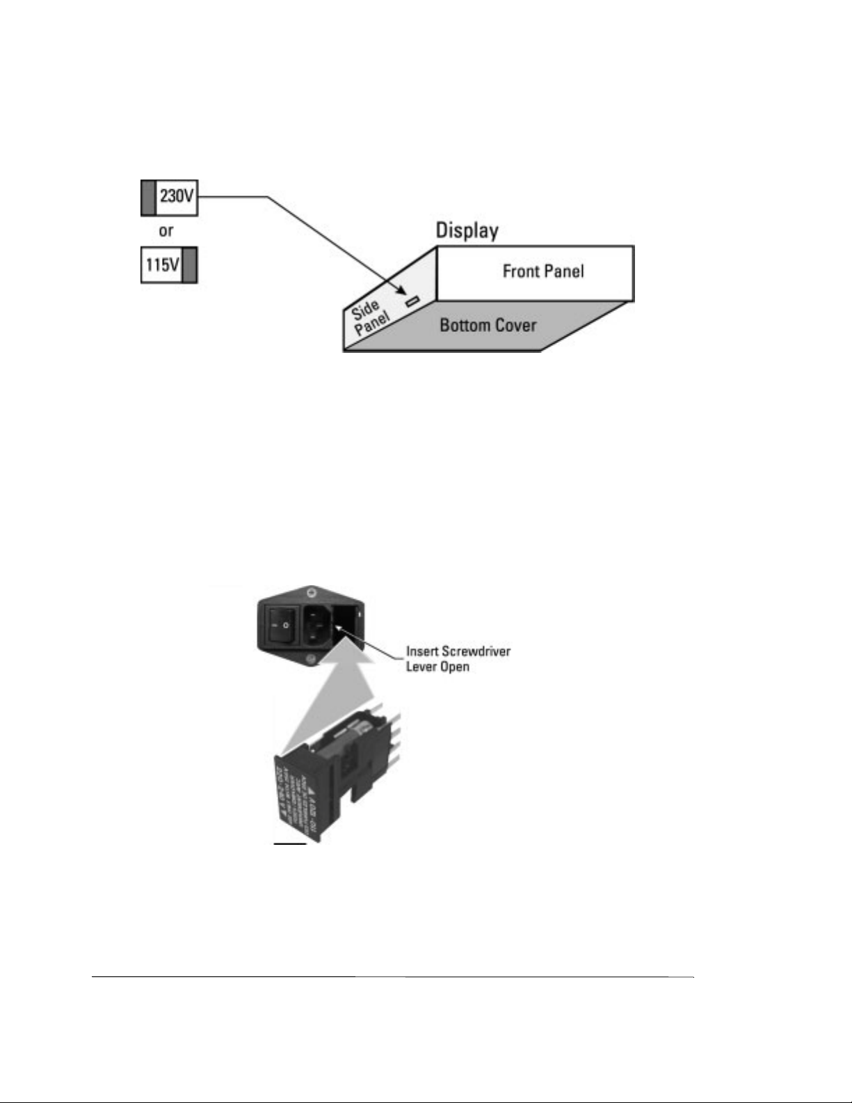
Line Voltage Selection
Instrument (Agilent 70843) Line Voltage Selector
There is no Line Voltage Selector switch on the Agilent 70843. The instrument line input
circuits are auto-ranging and will operate at any voltage within the specified voltage range
(90 to 135 and 180 to 264 volts). The Line Input module (on the rear panel) incorporates
an ON/OFF switch - the `0' position is the OFF position. Refer to the paragraph on Line
Fuses on page 2-9 for advice on replacing fuses.
NOTE See page 2-10 for fuse ratings for 115 V ac and 230 V ac operation.
CAUTION Mains supply voltage fluctuations should not exceed +/-10% of the
nominal selected line voltage.
WARNI NG Appliance coupler (mains input power cord) on the rear panel is the power
disconnect device. Do not position the instrument such that access to the coupler
is impaired. If this instrument is mounted in a rack, access to the appl ian ce
coupler may be impaired. In such an event, make sure that the rack system, in
which the system is mounted, has a readily accessible device which will isolate
the product from the mains supply.
CAUTION This instrument has an autoranging line voltage input, be sure the
supply voltage is within the specified range.
WARNI NG For continued protection against fire hazard, replace the line fuse only with the
same type and line rating:
F 10A 250V for the 115V Setting (Agilent Part Number 2110-0051) or
F 7A 250V for the 230V Setting (Agilent Part Number 2110-0614).
The Display and Mainframe fuse ratings are 6.3A, 250V (Agilent Pa rt Number
2110-0703) for both 115 and 230V ac operation.
The use of other fuses or materials is prohibited.
Display (Agilent 70004A) Line Voltage Selector
CAUTION Beforeyou connect the power cable to the display,check that the LINE
VOLTAGE SELECTOR switch is set for the correct line voltage
source.
If the wrong voltage is selected, one of the following may happen:
If 115 V line operation is selected and you connect to a 230 V ac line
power source, the fuse may blow.
If 230 V line operation is selected and you connect to a 115 V ac line
power source, the instrument will not power-on correctly.
2-8
Page 45
Installation
Preparation for Use
The LINE VOLTAGE SELECTOR slide switch is located through a slot in the left sidepanel.
Line Fuses
The line fuses of the instrument, display and mainframe are located in the line-module
housings on the rear panel.
Accessing the Agilent 70843 Line Fuse
1. Make sure that no power cable is connected to the line-module housing.
2. Use a screwdriver to lever open the fuse holder. There are two fuses in the fuse holder;
one is the fuse for 230V operation and the other one is for 115V operation.
70843 Fuse Replacement
2-9
Page 46

Installation
Preparation for Use
Accessing the Display (Agilent 70004A) Fuses
To access the fuses:
1. Ensure no power cable is connected to the line-module housing.
2. Use a screwdriver to lever open the fuse holder. A spare line fuse is located inside the
fuse holder.
Display Fuse Replacement
Fuse Ratings
The fuse ratings and the part numbers for 115 V ac and 230 V ac operation are listed
below:
• Agilent 70843: 115 V operation - F 10 A, 250 V, (part number 2110-0051).
• Agilent 70843: 230 V operation - F 7 A, 250 V, (part number 2110-0614).
• TheDisplay fuse rating is 6.3 A, 250 V (Agilent 2110-0703) for both 115 and 230 V ac
operation.
HP-MSIB Address Switches
The HP-MSIB address of an Agilent 70843 error performance analyzer is factory preset to
row 0, column 18. Both error detector and pattern generator share the same HP-MSIB
address.
If you wish to change the HP-MSIB address, ensure you are fully aware of the HP-MSIB
address protocol.
2-10
Page 47

Installation
Preparation for Use
Factory Preset HP-MSIB Addresses
The factory preset HP-MSIB addresses (row , column) are listed below:
Agilent 70004A display: 0, 20
Agilent 70843 error performance analyzer: 0, 18*
Agilent 70340A clock source: 1, 19
* The column value defines the factory-preset GPIB address.
Agilent 70843 Address Switches
These are accessed via the instrument rear panel. The factory preset settings are shown in
the following diagram:
2-11
Page 48

Installation
Preparation for Use
Agilent 70340A Clock Source Module Address Switches
These switches are located on the clock source rear panel. The factory preset switch
settings are row 1, column 19 as shown in the following diagram:
Agilent 70004A Display Address Switches
These are located on the rear panel of the Agilent 70004A display, it has no row switches
(it defaults to row 0) - only column switches (the factory preset settings are shown in the
following diagram):
GPIB Address Switches
The HP-MSIB address switches also act as GPIB switches. If you want your system to
communicate over the GPIB:
The row switches must be set to 0.
The column switches define the GPIB address.
2-12
Page 49

Installation
Preparation for Use
If you want to change the GPIB address (for example, use an address that is different from
that defined by the column switch settings), it is recommended that you use the Display,
Address Map function keys as follows:
CAUTION Itis not recommended that you change the GPIB address using the HP-
MSIB/GPIB switches as these also change the HP-MSIB address. If
the HP-MSIB address protocol is violated your system will fail to
operate.
To Change the GPIB Address
1. Press the Display fixed label key.
2. Press the left-menu softkey.
Address Map
DISPLAY
3. Rotate the large display knob clockwise until the green box rests on the 70843 Err Perf
Anl.
4. Press , select an address using the numeric keypad then press
HP-IB ADDRSET
ENTER
.
Factory Preset GPIB Addresses
The error performance analyzer GPIB address is factory preset to 18 (column part of
HP-MSIB switch setting).
Bench Operation
Plastic feet are included with Mainframes and stand-alone instruments to provide bench
operation convenience. The plastic feet are self-aligning when systems are to be stacked.
Rack Mount Installation
Front handles must be removed when fitting the system rack mount options.
Agilent 71612 option 1CM - rack mount kit (part number 15810A)
Agilent 71612 option 1CP - rack mount kit with handles (part number 15811A)
Agilent 70843 option 1CM - rack mount kit (part number 15810-60001)
Agilent 70843 option 1CP - rack mount kit with handles (part number 15811-60001)
2-13
Page 50

Installation
Preparation for Use
The rack mounts available are illustrated below. Angled brackets (Agilent 12679C) may
be ordered to provide additional rear or side support for the rack mounted instruments.
2-14
Page 51

Installation
System Installation
System Installation
The following figure shows an error performance analyzer system.
70004A
Display
70340A
Clock
Source
70843 Error
Performance
Analyzer
Accessories
The following cables, connectors and terminations are suppled with your system.
Cables
4 off SMA cables, part number 8121-0590; use to connect the clock/data ports.
Connectors
5 off APC - 3.5mm female to female, part number 5061-5311; use as savers for pattern
generator clock/data outputs and error detector data input.
2 off APC - 3.5mm male to female, part number 1250-2472; use as savers for error
detector clock input and trigger output.
Terminations
7 off SMA terminations, part number 1250-2121; use on unused clock/data outputs.
2-15
Page 52

Installation
System Installation
Procedure
Use the following procedure to install your Agilent 71612 series system.
CAUTION Ensure that no power cables are connected. Also check that the LINE
POWER switches are set to OFF.
CAUTION Ensurethatthe display linevoltage selector switchesare set for the line
voltage being used, also check the fuse ratings, see pages 2-8 and 2-10.
1. Install the Agilent 70340A clock source module into the display. Refer to Installing an
Agilent 70340A Clock Source Module into a Display on page 2-20.
2. Arrange the Display and Agilent 70843 for bench operation. The plastic feet on the
Display and Agilent 70843 are self-aligning when systems are stacked. To rack mount
your system, refer to Rack Mount Installation, see page 2-13.
3. Connect the HP-MSIB cables as follows:
CAUTION Your system mustbe powered down when connecting or disconnecting
HP-MSIB cables.
The diagram shows the systems viewed from the rear.
4. Connect the CLOCK IN port of the Agilent 70843 pattern generator to the CLOCK
OUT of the clock source module.
CAUTION When tightening SMA connectors and terminations, ensure that
the maximum torque setting used is 0.9 N-m.
2-16
Page 53

Installation
System Installation
NOTE The other front panel ports on the Agilent 70843 pattern generator and
error detector are interconnected according to theapplication you want
to undertake. All the necessary cables, adapters and 50Ω terminations
are provided with your instrument. Unused ports mustbe terminated in
50Ω.
CAUTION Checkthe power cables you intend to use for damage before powering
on your system, see the Power Cables on page 2-7.
5. Connect power cables to your system then connect the cables to the power outlets.
Your system is now ready for System Verification, see page 2-18.
2-17
Page 54

Installation
System Verification
System Verification
This section contains procedures which will enable you to verify that your error
performance analyzer has been correctly installed.
Error Performance Analyzer System Verification
The Agilent 70843 error detector and pattern generator are connected back-to-back. then
the system selftest and instrument preset parameters are used to verify correct installation.
A description of what you will see during selftest is given in System Selftest at Power-on,
see page 2-19 (since selftest takes only 15 seconds approximately to complete, you should
read the description before powering on your system).
1. Interconnect the front panel ports as shown below.
2. Prior to switching on your system, read Selftest at Power-on, see page 2-19. Switch on
the 70004A front panel and the 70843 front and rear panel power switches- wait
approximately 15 seconds for selftest to end.
3. Press the display key to set up the instrument preset parameters.
INST PRESET
4. Check that the displayed clock frequency is 1.000 GHz and that the ACT indicator on
the instrument is lit.
5. Press the display key, the ACT indicator should extinguish and an A should
DISPLAY
appear at the top left of the display.
6. Press the display key, the A should disappear and the ACT indicators should
MENU
light.
7. Press , , . W ait for the clock and
input & eye
data signals to align, then do a and wait for alignment to com-
0/1 THR AUTO CLK-DAT ALIGN
0/1 THR CENTER
plete.
8. Press . The GATINGindicator on the error detector and the Gate flag at
RUN GATING
the top right of the display should light.
9. Check that the displayed error count is 0.
If there are no errors, the system is ready for use.
2-18
Page 55

Installation
Selftest at Power-on
Selftest at Power-on
At power-on the error performance analyzer system performs a selftest (this takes
approximately 15 seconds to complete). During this time the display, instrument, clock
source and mainframe (option UKB instruments) operate as follows:
Display: The display is blank for the first few seconds of the selftest. It
then shows a multi-colored raster. The raster sweeps to the right,
to show a blue back-ground. For the remainder of the selftest the
display is as follows:
After selftest the display may continue to display the above, or
will display the module parameters present prior to the last power
down.
Agilent 70843: All front panel indicators are lit for approximately eight seconds
then extinguished for the remainder of the selftest.
After selftest the ACT indicator should light.
Clock Source Module: All front panel indicators are lit for approximately five seconds
then extinguished for the remainder of the selftest.
2-19
Page 56

Installation
Installing/Removing Modules
Installing/Removing Modules
This section describes how you install a clock source module into a Display and
Mainframe.
Installing an Agilent 70340A Clock Source Module into a Display
Use the following procedures to install your clock source into the display. To remove a
module, perform the steps in the reverse order.
1. Set the display LINE power switch to off.
2. Open the front panel door then insert the module.
3. Secure the module by pressing against its front panel while tightening the hex-nut latch
with an 8 mm hex-ball driver.
When removing a clock source module, disconnect any cables that may be connected to
the rear panel.
2-20
Page 57

3
3 System Overview
Page 58

System Overview
Configurations
Configurations
The Agilent 71612 Series of Gigabit testers can be configured into one of the following
systems:
System Options
• Agilent 71612 option UHF: 1-12.5 Gb/s error performance analyzer system
• Agilent 71612 option UHG: 1-12.5 Gb/s pattern generator system
• Agilent 71612 option UHH: 0.1-12.5 Gb/s error detector system
Each system comprises an Agilent 70004A display and an Agilent 70843 pattern
generator or error detector or both.
An Agilent 71612 error performance analyzer system is shown in the following figure:
70004A
Display
70340A
Clock
Source
70843 Error
Performance
Analyzer
3-2
Page 59

System Overview
Configurations
Additional System Options
• Agilent71612 option UHJ: error location analysis (cannot be ordered with option UHG
pattern generator system)
• Agilent 71612 option 100: add clock source
Refer to Chapter 1, General Information, for a complete list of Agilent 71612 options.
Agilent 70843 Instrument Options
• Agilent 70843 option UHF: error performance analyzer (0.1 to 12.5 Gb/s)
• Agilent 70843 option UHG: pattern generator (0.1 to 12.5 Gb/s)
• Agilent 70843 option UHH: error detector (0.1 to 12.5 Gb/s)
• Agilent 70843 option UHJ: error location analysis (not available with option UHG)
Documentation Overview
The manuals supplied with each system are listed in the following table:
Element Product Number Manual Part Number Comments
System 71612 Operating/
Programming
Display 70004A Operation
Installation/
Verification
Clock source 70340A User’s Guide 70340-90001 Thismanual is only
Instrument 70843 Operating/
Programming
71612-90016 This manual is supplied
with all systems.
70004-90031
70004-90005
71612-90016 This manual is supplied
These manuals are
supplied with all
systems.
supplied with 71612
option 100 (add clock
source).
with all instruments.
3-3
Page 60

Page 61

4
4 Operating Features and
Specifications
Page 62

Operating Features and Specifications
Introduction
Introduction
This chapter lists and describes the features and specifications of an Agilent 70843 error
performance analyzer. Refer to Chapter 1 General Information for advice on instrument
options and accessories.
Warm-up
All specifications valid after a 30-minute warm-up period.
Operating Temperature Specification
NOTE For Rack Mount Systems see page 2-5 for cooling considerations.
Temperature range for specified operation:100 MHz to10 GHz, 10ºC to 40ºC
10 GHz to12.3 GHz, 10ºC to 35ºC
12.3 GHz to12.5 GHz, 20ºC to 30ºC
Calibration Interval
Recommended 2 years
4-2
Page 63

Operating Features and Specifications
Pattern Generator
Pattern Generator
External connections
Patterns
PRBS Test Patterns
2^31−l - polynomial D31 + D28 + 1 = 0, inverted
2^23−1 - polynomial D23 + D18 + 1 = 0, inverted (as in CCITT Rec O.151)
2^15−1 - polynomial D15 + D14 + 1 = 0, inverted (as in CCITT Rec O.151)
2^10−1 - polynomial D10 + D7 + 1 = 0, inverted
2^7−1 - polynomial D7 + D6 = 1 = 0, inverted
Zero Substitution/Variable Mark Density
Test Patterns
8192 bits, based on 213−1PRBS
2048 bits, based on 211−1PRBS
1024 bits, based on 210−1PRBS
128 bits, based on 27−1PRBS
4-3
Page 64

Operating Features and Specifications
Patterns
Zero Substitution
Zeros can be substituted for data to extend the longest run of zeros in the above patterns.
The longest run can be extended to the pattern length −1. The bit following the substituted
zerosissetto1.
Variable Mark Density
The ratio of 1s to total bits in the above patterns can be set to 1/8, 1/4, 1/2, 3/4, or 7/8.
User-programmable test patterns
Variable length user patterns from 1 bit to 8M bits. Refer to Chapter 8 User Patterns and
Disk Operation andAppendixB,pageB-3,fordetailedinformationonuserpatterns.
Table 4-1 Pattern Granularity
Pattern Length Alternate Pattern Length Resolution
>4 Mbit >2 Mbit 256
>2 Mbit >1 Mbit 128
>1 Mbit >512 kbit 64
>512 kbit >256 kbit 32
>256 kbit >128 kbit 16
>128 kbit >64 kbit 8
>64 kbit >32 kbit 4
>32 kbit >16 kbit 2
≤32 kbit ≤16 kbit
1
Alternate test pattern - pattern generator only
Switch between two equal length user programmable patterns, each up to 4,194,304 bits,
under the control of a front panel key, GPIB or the auxiliary input port; changeover is
synchronous with the end of a word. The length of the alternating patterns should be a
multiple of 256 bits.
Two methods of controlling pattern changeover are available, oneshot and alternate. Refer
to the paragraph on the Auxiliary Input (on page 4-10) for further information.
NOTE The error detector is not affected by the pattern switching and is set to
pattern A when Alternate Pattern is selected.
4-4
Page 65

Operating Features and Specifications
Clock Input
Internal Disk Drive
The Agilent 70843 internal disk drive is used to store user data patterns. The disk supports
MSDOS format 1.44 Mbyte 3.5 in. disks only. The disk functions supported are:
• Pattern read
• Pattern write
• Disk format
• Pattern delete
Refer to Chapter 8 User Patterns and Disk Operation for more detailed information on
disk operation.
Clock Input
Input for the clock to the pattern generator
Features
• Set frequency - when used with Agilent 70340 clock source
• Set frequency step - when used with Agilent 70340 clock source
• Measure frequency
• Set output level of clock source
Specifications
Frequency range: 100 MHz to 12.5 GHz
Interface: 0.45 V to 0.90 V pp (≤10 GHz),
0.63 V to 0.9 V pp (>10 GHz) dc coupled
Impedance: 50Ω nominal
Connector: SMA female connector
Amplitude: 450 to 900 mV pp
Note: Do not apply dc volts.
4-5
Page 66

Operating Features and Specifications
Data and Data (inverted) Outputs
Data and Data (inverted) Outputs
The following pattern generator data output features are accessed using the
data output
key and its menu of softkeys.
Features
• Polarity - normal or inverted data.
• Data high level adjust.
• Data amplitude adjust.
• External termination voltage 0/−2V or ac coupled.
• External attenuator set 0 to 40 dB for 0V termination.
• Delay v clock adjust.
• Output ON/OFF selection.
• Vertical data-eye cross-over adjust.
• Independent control of high level, amplitude and ON/OFF for DATA and DATA.
Data output features not controlled by data output softkeys
• Output gating - controlled by AUXILIARY INPUT port (see Auxiliary Input description on page 4-10).
• Error add - (see Error Add paragraph on page 4-8).
Specifications
Data outputs - main
Interface: complementary dc coupled, reverse terminated.
Impedance: 50Ω nominal.
Format: NRZ, normal or inverted.
Amplitude: 0.5 to 2 V pp in 10 mV steps.
Transition times: (10% to 90%) < 30 ps (typical at 2 V pp).
Jitter: typically less than 20 ps pp; <15 ps pp typical at 10 Gb/s
Offset (range): +1.5 V to −3.0 V in 10 mV steps.
Clock/data delay: ±1 ns in 1 ps steps (100 MHz to 500 MHz),
1 clock period (500 MHz to 12.5 GHz).
Resolution: ±1ps.
Connector: APC-3.5 male connector.
Terminations: 50Ω−2V; 50Ω ac coupled
4-6
Page 67

Operating Features and Specifications
Data and Data (inverted) Outputs
The following figures illustrate data/clock amplitude and high-level relationship for 0V
and −2V terminations.
Figure 4-1 Clock/Data Amplitude and High-Level Relationship with 0V
Termination
Figure 4-2 Clock/Data Amplitude and High-Level Relationship with −2V
Termination
4-7
Page 68

Error Add
Operating Features and Specifications
Clock and Clock (inverted) Outputs
Add errors to the data using the key and its menu of softkeys. There are three
error add
modes of operation:
Single: Adds single errors on demand.
Fixed: Fixederrorratiosof1errorin10nbits, n = 3, 4, 5, 6, 7, 8, 9.
External: Injects a single error in the transmitted test pattern on each rising edge at
the ERROR INJECT INPUT port.
Clock and Clock (inverted) Outputs
The following clock output features can be set using the key and its menu
of softkeys.
• Clock high level adjust.
• Clock amplitude adjust.
• External termination voltage 0/−2V or ac coupled.
• External attenuator set 0 to 40 dB (0V termination only).
• Independent control of high level and amplitude for CLOCK and CLOCK.
clock output
Specifications
Clock outputs - main
See figures 4-1 and 4-2 for amplitude and high-level specifications with 0V and −2V
termination.
Frequency range: 100 MHz to 12.5 GHz.
Interface: Complementary, dc coupled, 50Ω, reverse terminated.
Amplitude: 0.3 to 2 V pp in 10 mV steps.
Range: +1.5 to −3.0 V in 10 mV steps.
Connector: APC-3.5 mm male connector.
4-8
Page 69

Operating Features and Specifications
Subrate Clock & Data (inverted) Outputs
Subrate Clock & Data (inverted) Outputs
Four subrate Data outputs (parallel data out ports) and one subrate Clock output are
available. Subrate Data and Clock are at 1/4 the main Data and Clock rate. Subrate data is
inverted relative to the main data output. When the main data is a pure PRBS, the subrate
data is a PRBS at 1/4 the main data rate (every 4th bit is output). When a RAM based
pattern (including mark density and zerosub patterns) is selected the data pattern output
from each subrate port depends on the pattern length and will change if the trigger bit
position changes. Refer to Appendix B for additional information.
The following subrate features are provided:
Features
• Data high-level adjust.
• Data amplitude adjust.
• Clock high-level adjust.
• Clock amplitude adjust.
• Set Clock and Data to ECL.
• Set external termination voltage 0/−2V or ac coupled.
Specifications
Frequency range: 1/4ofmainclockrate.
Interface: dc coupled, 50Ω, reverse terminated.
Amplitude: 0.5 V to 1 V pp in 10 mV steps.
Range: 0to−1.5 V in 10 mV steps.
Connector: SMA female connector.
Trigger Output
Provides an electrical trigger synchronous with the pattern for use with an oscilloscope or
other test equipment. It operates in two modes, pattern and divided clock. Refer to pages
7-16 and 7-17 for more information on Trigger Outputs.
Features
• Pattern or clock trigger
• Pattern trigger position set
4-9
Page 70

Operating Features and Specifications
Auxiliary Input
Pattern Mode
In pattern mode the trigger is synchronized to repetitions of the output pattern.
PRBS 2^31−1, 2^23−1, 2^15−1, 2^10−1, 2^7−1
Pulse synchronized with a specified bit in the pattern. The repetition rate is 1 pulse for
every 32 pattern repetitions.
Alternate pattern
Pulse at bit 0 of the pattern or trigger output alternates with pattern.
All other patterns
Pulse synchronized to any bit of the pattern. The repetition rate is a function of the pattern
length. The rate is the lowest common multiple of 256 and the length example:
• Pattern length = 32767 => 1 pulse/256 pattern repetitions
• Pattern length = 32768 => 1 pulse/pattern repetition
Divided Clock Mode
In divided clock mode the trigger is a square wave at the clock rate divided by 32 or 8.
NOTE Clock divided by 8 trigger has lower jitter. Clock divided by 32 has
same timing relative to data as the pattern trigger.
Interface
Pulse width: 32 bits
Pulse amplitude: Output terminated 50Ω to 0V; High: 0V nominal; Low: −0.4 V
nominal
Impedance: 50Ω nominal
Interface: dc coupled
Connector: SMA female connector
Auxiliary Input
The AUXILIARY INPUT port can be used to control user programmable alternate test
patterns or inhibit data output (force the data to a fixed low level).
4-10
Page 71

Operating Features and Specifications
Auxiliary Input
Alternate Pattern Selected
The instrument will output one of two patterns (A or B) at the end of either pattern. The
auxiliary input controls which pattern is output in one of two modes:
• Oneshot - a rising edge on the auxiliary input inserts a single version of B pattern into
repetitions of pattern A.
• Alternate - The logic state of the signal at the auxiliary input determines which pattern
is output. A logic ‘0’ will output pattern A.
NOTE In both cases, switching between patterns is at the end of a pattern and
is hitless (error free).
Data Output Inhibit (Gating mode)
If an Alternate Pattern is not selected, an active (TTL low) signal at the auxiliary input
port forces (gates) the data to a logic zero at the next 32-bit boundary in the pattern. See
the following figure:
NOTE Connecting an external termination to the auxiliary input will pull it
low and disable the data output.
Interface
Interface: dc coupled
Levels: TTL levels (active low)
Connector: BNC female connector
To Select Oneshot Mode
Select then set to and to
ONCE
To Select Alternating Mode
Select then set to and to
ALT
pattern
.
pattern
.
ALTPAT AUX USR AUX ALTPAT ALTONCE
ALTPAT AUX USR AUX ALTPAT ALTONCE
4-11
Page 72

Operating Features and Specifications
Error Inject Input
Error Inject Input
The external ERROR INJECT INPUT adds a single error to the data output for each rising
edge at the input.
Interface
Levels: TTL compatible (active low)
Connector: BNC female connector
Minimum pulse width: 100 ns
Status Indicators
Pattern Generator indicators
• Clock Loss: Indicates nominal low clock power at clock input port.
Error Detector indicators
• Clock Loss: Indicates nominal low clock power at clock input port.
• Data Loss: Indicates no data transitions in the last decisecond.
• Sync Loss: Error detector out of pattern sync (see sync gain/loss criteria spec).
• Gating: Measurement in progress.
• Errors: Indicates one or more data errors in the last decisecond.
General instrument indicators
• GPIB RMT, TLK, LSN, SRQ: standard indicators
• MSIB ACT, ERR: standard indicators
• VOLT/TEMP: instrument has detected over-temperature or abnormal voltage condition
and has shut down. Power cycle required to recover.
Rear Panel Switches
• 8-way DIL switch for GPIB/MSIB address.
• Line input module on/off switch.
4-12
Page 73

Operating Features and Specifications
Error Detector
Error Detector
External connections
Clock Input (error detector)
Features
• Switchable termination voltage 0V or −2V.
• Input frequency measurement.
Specifications
Frequency Range: 100 MHz to 12.5 GHz.
Amplitude: 450 to 900 mV pp.
Range: +1.5V to −4V.
Interface: dc coupled.
Impedance: 50Ω.
Input termination: switchable 0V or −2V.
Sensitivity: <100 mV pp (typical at 10 Gb/s).
Connector: APC-3.5 mm female connector.
4-13
Page 74

Operating Features and Specifications
Data Input
Data Input
The error detector data input port offers the following features, selectable using the
input & eye
key and its menu of softkeys.
Features
• Data polarity - normal or inverted data.
• Auto or manual slicing.
• Set manual slicing level.
• Termination voltage - 0/−2V.
• Measure auto slicing voltage.
• Clock/Data delay adjust.
• Clock/Data alignment.
• 0/1 threshold centre.
Specifications
Impedance: 50Ω to 0V or −2V, dc coupled.
Format: NRZ.
Amplitude: 0.5 to 1 V pp.
Sensitivity: <50 mV pp (typical for 2 ^23−1 PRBS input at 10 Gb/s 0V high level).
<100 mV pp (typical for 2 ^23−1 PRBS input at 12.5 Gb/s 0V high level).
Decision threshold range: +1V to −3V in 1 mV steps.
Range: +1.5V to −4V.
Data input range: +1.5V to −4V.
Clock/Data phase alignment: ±1nsin1pssteps(100MHzto3GHz)
1 clock period (3 to 12.5 GHz) in 1 ps steps.
Connector: APC-3.5 mm male connector.
Pattern Trigger Output (error detector)
Provide an electrical trigger synchronous with the error detector reference pattern.
4-14
Page 75

Operating Features and Specifications
Errors Output
Features
• Pattern or clock trigger.
Pattern Mode
In pattern mode the pulse is synchronized to repetitions of the output pattern.
PRBS 2^31−1, 2^23−1, 2^15−1, 2^10−1, 2^7−1
Pulse synchronized to repetitions of the pattern. The repetition rate is 1 pulse/32 pattern
repetitions.
All other patterns
Pulse synchronized to repetitions of the pattern. The repetition rate is a function of the
pattern length. The pulse occurs at that lowest common multiple of 256 and the length
example:
• Pattern length = 32767 => 1 pulse/256 pattern repetitions
• Pattern length = 32768 => 1 pulse/pattern repetition
Divided Clock Mode
In divided clock mode the trigger is a square wave at the clock rate/8.
Specifications
Interface: dc coupled.
Impedance: 50Ω nominal.
Connector: SMA female connector.
Amplitude: High: 0V nominal; Low: −0.4 V nominal.
Errors Output
Provides an electrical signal to indicate received errors. The output is the logical ‘OR’ of
errors in a 32-bit segment of the data.
Features
• Pulse length switchable - RZ or stretched.
4-15
Page 76

Operating Features and Specifications
Gating Input
Interface
Format: RZ, active high.
Interface: dc coupled.
Impedance: 50Ω nominal.
Amplitude: High: 0V nominal; Low: −0.4 V nominal.
Pulse Width: For 1-bit error: 16 clock periods nominal or stretched 200 ns.
Connector: BNC female connector.
Gating Input
The Gating Input is used to enable the error counters including during burst gating mode.
In both these cases the error counters will always be enabled for a multiple of 32 pattern
bits. When the Error Detector's clock and data inputs are continuous the Gating Input
alone provides sufficient control of the bit error counting functions. If, however, the data
input is not continuous then this input should be used together with the Burst Gating
mode described under Gating Menu on page 7-35.
The error counter control provided by the Gating Input is independent of the
Measurement Gating configured via the Error Detector gating control configuration
menu and controlled via and . Refer to Measurements on
RUN GATING STOP GATING
page 4-18 and Measurement Period on page 4-22.
Interface
Levels: TTL levels (see note below).
Pulse Width: 10µs at 100 MHz; 1µs at 10 GHz.
Connector: BNC female connector.
NOTE Connecting an external termination to the gating input will pull it low
and disable the instrument error counters. Gating resumes when the
Gating Input returns high.
4-16
Page 77

Operating Features and Specifications
Automatic Clock-to-Data Alignment
Automatic Clock-to-Data Alignment
Introduction
An important feature of the Agilent 70843 error detector is the ability to automatically
align the clock and data inputs such that the error detector samples in the middle of the eye
(in the time a xis). This reduces setting-up time as it automatically compensates for delays
in the clock/data paths, preventing unnecessary errors.
The delay point in the eye at which the error detector samples can also be set manually
using the softkey (part of the menu of softkeys).
DAT I/P DELAY
input & eye
Definition
In order for the system to align the clock with the data (at the error detector input) it must
find the edges of the data input eye.Theeye edge is defined as a data input delay point
where the Bit Error Ratio (BER) measured over a decisecond interval is less than or equal
to a pre-defined threshold, and another adjacent point which is greater than the threshold.
The Eye Edge Threshold can be set by the user to any value between 10-1and 10-7either
via the softkey or remotely.
EYE EDG THRSHLD
It is recommended that you perform the Clock-to-Data alignment procedure each time you
configure an Agilent 71612 Series error performance analyzer. Normally this would be
after setting up instrument parameters such as Pattern, Data Output (Level, Polarity) and
Data Input (0/1 threshold, polarity).
Eye Width
Each time a successful clock-to-data alignment procedure is performed the eye width is
calculated, and displayed on the EYE RESULTS page (select , then
EYE RESULTS
NOTE The clock/data alignment process time is pattern-dependent, and with
. This result can be added to the USER'S PAGE.
result pages
some large user-patterns alignment can take several minutes. If you
wish to select a user pattern, it is recommended that you first perform
clock/data alignment on a pure PRBS. This does not affect alignment
accuracy and can save you valuable time.
NOTE Ensure that the received clock frequency is stable before performing a
clock-to-data alignment procedure.
4-17
Page 78

Operating Features and Specifications
Measurements
Automatic 0/1 Threshold Center
The 0/1 threshold center operation is used to set the 0/1 threshold midway between two
points, top and bottom of the eye, where the bit error ratio is equal to a selectable
threshold. The eye height is calculated and displayed (on the EYE RESULTS page). The
BER selectable threshold is set using the key.
The function can be used to determine the optimum sampling point
0/1 THR CENTER
for asymmetric eyes, or on patterns with an unequal mark-density.
To perform a 0/1 Threshold Centering
EYE EDG THRSHLD
Select then press .
input & eye
0/1 THR CENTER
Data Input 0/1 Threshold
Introduction
There are three methods of determining the 0/1 Threshold of input signals at the error
detector data input; they are Manual, Automatic Track and Automatic Center.
If the signal at the error detector data input is a standard PRBS or a clean signal (no
excessive noise or jitter) with a 1:1 mark density, use the Manual or Automatic Track
Modes, otherwise use the Automatic Center mode.
Manual: 0/1 threshold can be set manually.
Range: +1 to −3V nominal
Resolution: 1 m V nominal
Automatic Track: Tracks the mean dc level of the input signal. The 0/1 threshold
calculated is displayed.
Automatic Center: The error detector sets the 0/1 threshold midway between two points,
the top and bottom of the eye, where the bit error ratio is equal to a
selectable threshold. The eye height is calculated and displayed.
Measurements
The error detector counts bit errors by comparing data bit-by-bit with the internallygenerated reference pattern. All measurements run during the gating periods with the
exception of Delta Error Count and Delta Error Ratio. These measurements run
continuously to enable user adjustments for minimizing errors. The measurements are as
follows, (refer to Appendix A for measurement definitions):
4-18
Page 79

Operating Features and Specifications
Measurements
• Bit Count
• Error Count
• Delta Error Count
• Error ratio
• Delta Error Ratio
• 0 - >1 Error Count
• 0->1ErrorRatio
• 1 - >0 Error Count
• 1->0ErrorRatio
• Errored Intervals - intervals seconds, deciseconds, centiseconds, milliseconds
• Error-free Intervals - intervals seconds, deciseconds, centiseconds, milliseconds
• Sync Loss Seconds
• Power Loss Seconds
• G.821 Error Analysis
The Bit Count result is provided in particular for use whenever the detector's Gating Input
is being used to enable the bit error counters both in Normal and Burst Gating modes.
Whenever the Gating Input is switching the measurement period is not continuous and
hence the number of measured bits will no longer be equal to the Gating Elapsed
multiplied by the Err Det Clock Freq. The ratio:
Bit Count
Gating Elapsed * Err Det Clock Freq
allows the user to confirm the proportion of the measurement gating period for which the
Gating Input enabled the clock and bit error counters.
Error Analysis
The Error Analysis is based on CCITT Rec G.821 and is derived from the bit error results.
• % Unavailability
• % Availability
• % Errored Seconds
• % Severely Errored Seconds
• Degraded Minutes
Power-loss Seconds
This is displayed as the number of seconds the error detector is not able to make
measurements during a gating period due to ac power loss. The gating continues to the end
of the selected period following a restoration of power.
4-19
Page 80

Operating Features and Specifications
Error Location (Agilent 71612 or Agilent 70843 Option UHJ)
Sync-loss Seconds
Displays the number of seconds the error detector lost pattern synchronization during a
gating period.
Frequency Measurement
The incoming clock frequency is measured and displayed to five significant digits.
Result Logging
Refer to Chapter 10 Data Logging for information on logging results.
Error Location (Agilent 71612 or Agilent 70843 Option UHJ)
Error location is available only for RAM-based patterns. It has three forms:
•BitBER
• Error location capture
•BlockBER
Bit BER
Bit BER measurements are measurements made on a specific bit in a RAM-based user
defined pattern. The specific bit is the “BER location” and is specified by an address. This
measurement aids in identifying systematic errors causing a specific bit to change value.
Measurements
• Bit BER - BER of the BER location
• Bit error count - error count of the BER location
• Delta bit BER
• Delta bit error count
Bit BER and Bit error count are affected by gating like normal BER. Delta bit BER and
delta bit error count run continuously like normal delta BER.
The BER location may be specified by the customer as an address. After the location is
specified gating is restarted if the instrument was gating before the location was specified.
Error l ocation capture
Error location capture allows you to capture the actual position of errored bits in a user
defined pattern.
4-20
Page 81

Operating Features and Specifications
Error Location (Agilent 71612 or Agilent 70843 Option UHJ)
To initiate a measurement select then . The
error location
CAPTURE ERROR
instrumentsearches for the first bit errored bit in the pattern. The address of the errored bit
will be displayed along with the bit pattern surrounding the highlighted errored bit (see
below). The instrument performs Bit BER, Bit error count, and also Delta Bit BER, Delta
bit count on the captured bit.
Select then to view the BIT: results.
result pages
OTHER RESULTS
After an error is located the instrument displays:
BIT: Error Address nnn
Data window xxxx xxxx xxxx xxxx xxxx xxxx xxxy xxxx
• xxx.. - pattern around error, 28 bits before error and 3 bits after error are displayed
• y - the reference value of the errored bit in inverse video
Block BER
Block BER measures the BER of a range of bits in the pattern. It replaces normal BER
measurements. Ranges of bits must be a multiple of 32 bits with the block specified by a
start location and block length. This measurement is essential when trying to locate the
cause of systematic errors which can affect a section of bits, for example a corrupt header
in a SONET or SDH frame.
Pattern sync is affected since normal BER is replaced by the block results.
In general bit or block BER is not measured on every repetition of the pattern. The number
of repetitions depends on the pattern length.
Table 4-2 Pattern Length/Number of Repetitions for Bit/Block BER
Pattern length Number of repetitions
Odd 256
Multiple of 2 128
Multiple of 4 64
Multiple of 8 32
Multiple of 16 16
Multiple of 32 8
Multiple of 64 4
Multiple of 128 2
Multiple of 256 1
4-21
Page 82

Operating Features and Specifications
Measurement Period
Measurement Period
The measurement period is configured from the menu accessed via
gating
Measurement Period Features
• Length: The length of the measurement period can be set as a time period, number of
bits or number of errors.
• Timed Measurement Period: Can be set from 1 second to 99 days, 23 hours,
59 minutes 59 seconds in 1 second steps.
• Number of Bits: The time for the number of bits to be received to a resolution of
1second.Canbesetfor10nbits,n=7to15.
• Number of Errors: Time for number of errors to be detected to a resolution of
1 second. Can be set for 10, 100 or 1000 errors.
• Real-time Clock: Provides time and date information for event logging. Battery back-
up allows clock to continue running when the instrument is switched off or power fails.
• Elapsed Time Indication: Shows elapsed time from the start of a gating period; resets
to zero at the start of each gating period; holds value when measurement stopped.
Gating modes
There are three gating (measurement timing) modes: Manual, Timed Single and Timed
Repeat.
Manual: Gating period is controlled by the and
RUN GATING STOP GATING
keys. Accumulating results are displayed throughout the measurement and the end of
measurement results are held until a new gating period is started.
Single: Gating period is started by pressing the key and terminates at
RUN GATING
the end of the gating period set by the user. Accumulating results are displayed
throughout the gating period and the end of gating results are held until a new gating
period is started.
Repeat: Similar to Single but when one timed gating period ends, a new identical
period starts. This continues until the measurement is terminated by pressing the
STOP GATING
key. The measurement results displayed during any period can be
the final results of the previous period or the accumulating results for the current
period. There is no “deadtime” between consecutive periods. The gating period
excludes any periods when the instrument is not powered.
4-22
Page 83

Operating Features and Specifications
Measurement Period
Gating Period Definition
• Time - 1 second to 99 days, 23 hours, 59 minutes, 59 seconds.
• Errors - 10, 100 or 1000.
• Bits - 1E07 to 1E15 bits.
All gating periods to 0.1s resolution.
Refer to Measurements on page 4-18 for details of the effect of switching the detector's
Gating Input during gated measurement periods.
Burst gating
Burst gating is always used together with the error detector GATING INPUT and is
available only with PRBS patterns 2^31−1, 2^23−1, 2^15−1, 2^10−1 and 2^7−1.
Although the Gating Input enables the clock and bit error counters, where the data input is
not continuous, the Gating Input is often not sufficient to allow the detector to be kept
synchronized throughout a series of bursts of the selected pattern. The only exception to
this is where the data input pattern resumes, at the time when the Gating Input becomes
active, from the pattern bit which would have been received had the data been continuous.
In this special case selecting manual Sync Mode, once pattern synchronization has been
gained. prior to the first deactivation at the Gating Input will allow error free reception. In
all other circumstances where the data input is not continuous, for example in the testing
of optical fibre loops, the instrument's Burst Gating mode should be selected.
A further requirement of this mode of operation is that a clock is provided at the Error
Detector's clock input all the time. Should it be necessary to use a clock recovered from
the data input during the measurements. then an external switch should be deployed to
switch between the recovered clock and a continuous clock (e.g. from the Pattern
Generator). In this configuration the switch should select the recovered clock whenever it
is available but the Gating Input should only go active after the recovered clock has
established a stable amplitude and a fixed phase with respect to the burst of pattern data
bits. Similarly the Gating Input should be deactivated prior to either the onset of any
transients in the recovered clock or the end of the data burst.
While in burst gating mode the error detector:
• Attempts to synchronize to the incoming data on every low to high transition of the
Gating Input.
• Following each synchronisation attempt the detector counts bits and errors while the
Gating Input remains high.
• As is the normal function of the Gating Input, all measurement counters are disabled
whenever the Gating Input is low.
4-23
Page 84

Operating Features and Specifications
Pattern Synchronization
NOTE The Synchronization threshold does not affect the error pattern
synchronization attempt but will affect the instrument's “SyncLs”
status.
While Burst Gating is selected the only available Gating repeat mode
is manual untimed.
If the received data is errored during the synchronization attempt all
measured error counts are invalid.
The received clock must be continuous when burst gating is enabled.
Pattern Synchronization
Synchronization Modes
Synchronization to the incoming pattern can be performed automatically or manually. In
manual mode, the START SYNC softkey forces the error detector to attempt
synchronization with the received pattern.
Sync Gain Loss Criteria
The criteria for gaining or losing synchronization is the error ratio in a 1 ms interval.
Selectable error-ratio thresholds of 1E−1to1E−8 are provided. Refer to Appendix B
Operating Notes for advice on setting sync thresholds.
Synchronization Times
• PRBS patterns - <0.2s
• STM64 frame at 10 GHz - <2.8s
• <10 kbit pattern, >1 GHz - <1s
Audible O utput
The instrument has an audible output which varies with error rate. The effect of changing
error rate is:
• Isolated errors - output produces a 100 ms tone.
• Other error rates - 5% change in error rate produces an audible change.
4-24
Page 85

Operating Features and Specifications
Logging to External Printer
The audible output may be switched off or set to one of 15 volume levels. An audible
output can also sound when sync loss occurs; selectable with the key
on the menu.
sync & audio
AUDIO SYNCLS
Logging to External Printer
Functions
• Log on demand.
• Logging on/off.
• Log on error, end of gating period, error rate>threshold, alarms.
• Set logging threshold.
• Select GPIB controller capability.
• Select GPIB printer (HP DeskJet supported).
• Squelch on/off.
Refer to Chapter 10 for a detailed description of the measurement and status logging
functions and, where the logged output is to be directed to an external GPIB controller, to
the Agilent 71612 Programming Manual (at the rear of this manual).
To Set Up Your Own Display of Results or Status Information
The Agilent 71612 Series System gives you the opportunity to display on the screen a
page containing results or status information important to you. This is called the User's
Page and is setup as follows:
The following procedure shows you how to display and view the current User's Page
selections, and edit (or build) the page to show your own choice of results or status
information.
The process of editing the User's Page is referred to as Building the User's Page, and this
is accomplished using the softkey.
build usr-pge
Procedure
Select and View the User's Page
1. Press the hardkey, then the softkey.
result pages
USER’S PAGE
4-25
Page 86

Operating Features and Specifications
To Set Up Your Own Display of Results or Status Information
The User's Page is now displayed and shows the results or status information selected by
the previous user.
To Build Your Own User's Page
1. Select , , .
result pages
You can now select from the choices offered in the menu of softkeys
USER’S PAGE build usr-pge
build usr-pge
and build up the display to show the status or results information you wish. As you select
a softkey the display will change to reflect your choice; the softkey selected is underlined.
Refer to Build User Page Menu Map on page 6-16 for a chart of the selections offered.
4-26
Page 87

5
5 Getting Started
Page 88

Getting Started
Introduction
The purpose of this chapter is to instruct first time users how to quickly become proficient
at operating the Agilent 71612 Series error performance analyzer.
Using the Agilent 70004A Display
The Agilent 70004A display serves as the front panel for instruments in the Agilent
71612 Series Systems, and as your window for viewing current system configuration and
measurement results. The Agilent 70004A display has 14 (7 on each side of
the screen), keys above and below the screen, and 15 instrument
FIXED LABEL
hardkeys. All instrument functions/parameters are set up using these keys.
softkeys
Figure 5-1 Agilent 70004A Display
Key Notation
Throughout this manual indicates softkey labels. Display fixed label keys and
keys on the instrument hardkey panel are shown thus and
instrument hardkey
5-2
softkey
FIXED LABEL
.
Page 89

Getting Started
Display Fixed Label Keys
Fixed Label keys select major system functions such as PRINT, PLOT, INSTR PRESET,
DISPLAY or MENU. The two most important keys and are explained
DISPLAY MENU
on pages 5-4 and 5-5. Refer to the Agilent 70004A display Operation Manual for detailed
information on fixed label keys.
Instrument Hardkeys
Hardkeys are the keys on the panel to the left of the display knob (RPG knob). Use these
keys to gain instant access to primary instrument functions.
Parameter Control Keys
Display knob Use the display RPG knob to change parameters and select
operating values.
Numeric Keypad Use the numeric keypad to enter numeric values.
▲ ▼
Use the two step keys to change parameters up or down.
Instrument Softkeys
The softkeys around the perimeter of the display screen are used to select instrument
functions. The functions are organized in groups, called softkey menus.
NOTE Softkeys that are selected are displayed in inverse video or are
underlined.
Softkeys and Windows Color Coding
Softkeys and windows are color coded to indicate the primary instrument functions with
whichtheyareassociated,theyare:
• blue softkeys/window: assigned to Results Page occupies two thirds of screen.
• green softkeys/window: assigned to pattern generator/error detector configuration
• yellow softkeys - green/yellow window: assigned to Pattern Editor
• grey softkeys/window: assigned to user pattern selection and save.
• Softkeys that are “greyed out” are not valid for the currently selected instrument
function.
Multi-State Functions
Some softkeys switch between two states, such as and
SYNC AUTO/MAN
. An underline on the key labels indicates which keys and conditions
LOGGING OFF ON
are selected.
5-3
Page 90

Getting Started
To Set Up the Display
To configure the system correctly it is important to first set up the display, and then
configure the display to show instrument status. System functions are therefore split into
two groups as follows:
• Display Functions
• Instrument Functions
These functions are explained in the following paragraphs.
Display Functions
Display functions are accessed using the fixed label key. Pressing the
DISPLAY
key provides the softkeys on the left and right of the display as shown below,
DISPLAY
enabling display functions to be set up. Refer to the Agilent 70004A display Operation
Manual for detailed information on display operation softkeys.
Figure 5-2 Display Softkeys
5-4
Page 91

Getting Started
Instrument Functions
Primary Instrument functions are accessed using the keys on the instrument hardkey panel
or by pressing the fixed label key.
Both methods enable menus of softkeys which give access to all instrument functions. The
following figure illustrates the primary instrument softkeys when is pressed. For
each softkey shown there is a corresponding key on the instrument hardkey panel, except
for the softkey.
misc
MENU
MENU
Figure 5-3 Instrument Softkeys
5-5
Page 92

Getting Started
System Turn-On
System Turn-On
Introduction
The getting started procedures assume that the Agilent 71612 series systems have been
correctly installed and configured as described in Chapter 2 Installation.
WARNI NG Beforeturningthe system on,make sure it isgroundedthroughthe
protective conductor of the ac power cable to a socket outlet
provided with protective earth contact. Any interruption of the
protective (grounding) conductor inside or outside the system, or
disconnection of the protective earth terminal, can result in
personal injury. (Refer to page 1-2 for safety considerations).
CAUTION Do not turn on the Agilent 71612 Series Systems until they have been
configured and fused for the available line voltage, and safely
connected to the power line (115V or 230V).
CAUTION Do not attempt to replace or remove clock modules while instruments
are powered up as it may damage modules. Switch off the Agilent
70004A Display before replacing or removing modules.
NOTE The Agilent 71612 Series Systems will not function correctly unless
each instrument in the system is cabled correctly for HP-MSIB
operation, and each instrument is powered up. Refer to Chapter 2
Installation for information on cabling.
5-6
Page 93

Getting Started
Making Your First Measurement
Making Your First Measurement
Introduction
The following procedure is designed to give you confidence in using the instrument
and by performing a simple error measurement. It shows you
hardkeys
softkeys
how to cable the system and set up the error performance analyzer to perform a simple
back-to-back error measurement. The procedure also introduces you to many of the
instrument operating features.
Procedure
Ensure that 50Ω cables are used to connect the Agilent 70843 IN/OUT ports. All the
cables, adapters and terminations you need are supplied with your instrument.
1. Connect the Agilent 70340A clock source RF OUTPUT port to the pattern generator
CLOCK IN port.
2. Connect the pattern generator DATA OUT and CLOCK OUT ports to the error
detector DATA IN and CLOCK IN ports respectively. Terminate any unused ports
with 50Ω terminations (Agilent part number 1250-2121). See Figure 5-4 on page 5-8.
Ensure the Agilent 70843 error performance analyzer and Agilent 70004A display rearpanel HP-MSIB ports are connected.
Initial Switch On
3. Switch on power to the Agilent 70843 and the Agilent 70004A display. All instrument
and display LEDs will illuminate and then extinguish after a few seconds. The display
will cycle through a range of colors, give a display indicating Agilent 70004A DIS-
PLA Y and a message stating For instrument display press DISPLAY then NEXT
INSTR, and finally display the status of the instrument selected before the last power
down. The ACT LED on the Agilent 70843 will be illuminated when it has control of
the keyboard.Wait until the display settles to indicate instrument status before continu-
ing with this procedure. If instrument status is not displayed, press then
NEXT INSTR
.
Initial settings
4. Before you perform a measurement you must first configure the system to suit your
application. Choose your own configuration using the instrument hardkeys and
softkeys (refer to the pull-out card in the tray beneath the display for help) or select one
of three stored predefined, complete instrument configurations. They are PRESET 0,
PRESET 1 and PRESET 2.
DISPLAY
5-7
Page 94

Getting Started
Making Your First Measurement
To select PRESET 0 press the display key, and to select PRESET 1 or
PRESET 2 select , , then or
Preset 2
trigger & setup
.
INST PRESET
recall setup Preset 1
For this procedure we set the error performance analyzer to its default values by selecting PRESET 0. Refer to Chapter 9 for a list of settings for each PRESET.
5. Press the green key.
INST PRESET
Figure 5-4 System Back-to-Back Connection
Perform a data eye measurement
In the following steps the data eye edge threshold is set, and the clock and data inputs
aligned such that the error detector samples in the middle of the eye (in the time axis).
6. Before performing the measurement select , then select
EYE RESULTS
. No eye results will be displayed until clock-data alignment is
performed in step 9 of this procedure.
7. Press the hardkey on the display hardkey panel.
5-8
input & eye
result pages
Page 95

Eye Edge Threshold
Getting Started
Making Your First Measurement
8. Set to , then select and select a
0/1 THR AUTOMAN AUTO EYE EDG THRSHLD
threshold using the numeric keypad. For example, to select a threshold of 1.00E−03;
enter 1.00 using the keypad, then press the softkey and enter 3 using the keypad,
then press .
9. Press the softkey. If clock-to-data alignment is successful, the
ENTER
CLK-DAT ALIGN
e
Status line at the center of the screen reads clock to data input delay aligned.
Automatic 0/1 Threshold Center
On data signals with an unequal mark-density perform an automatic 0/1 threshold center
operation as follows:
10.After performing the clock to data alignment select the softkey.
0/1 THR CENTER
The Status line at the center of the screen will indicate 0/1 input threshold centering in
progress and 0/1 data input threshold centered when complete.
To Select a Measurement Gating Period
11.Press the hardkey. The gating mode currently selected is MANUAL, try
selecting a 20 second SINGLE gating period.
12.Press , then , use the numeric keypad
and softkey to select a 20 second gating period. Proceed to step 13, or read
the following note for alternative gating choices.
gating
SINGLE GATE BY TIME GATING PERIOD
SECONDS
NOTE The instrument is currently set to gate by time; two other gating period
choices are also provided, they are: gate by errors and gate by bits. To
select either of these gating choices select the appropriate softkey.
To Start a Measurement
13.Press the hardkey. Note the illuminated Gating LED on the error
detector front panel and the Gate flag at the top right of the screen.
RUN GATING
Viewing Results and Introducing Errors into the System
14.Since there were no errors introduced into the system there are no errors measured. To
introduce errors into the system and obtain a meaningful result proceed as follows:
15.Select the hardkey. The instrument offers you the choice of adding single
errors, errors at a fixed rate or errors from an external source. For this procedure select
a fixed rate of 1E−5. Proceed to step 16.
error add
5-9
Page 96

Getting Started
Making Your First Measurement
To Select a Fixed Error Rate
16.Select , then choose an error rate of 1E-5. The error detector front
ERR-ADD FIXED
panel ERRORS LED will be ON and an Errors flag illuminated at the top of the
screen.
To Add External Errors
Connect an external error signal source to the pattern generator ERROR INJECT INPUT.
A single error is added to the data output for each rising edge at the input.
Start a New Measurement
17.Select
RUN GATING
To View Measurement Results
18.Press then and view results at the end of the gating
result pages
MAIN RESULTS
period. A typical results display is given in the following figure.
19.The error detector (Main Results) are displayed; this is only one of seven result pages
you can select to view instrument status or configuration.
20.Try selecting each of the softkeys and view the error detector results for
result pages
each selection.
This concludes your first measurement using an Agilent 71612 Series error performance
analyzer.
5-10
Page 97

Getting Started
To Verify/Demonstrate the Capture Error Feature (Option UHJ
instruments)
To Verify/Demonstrate the Capture Error Feature (Option U HJ instruments)
The following procedure can be used to demonstrate capturing an error, or verify that the
instrument is operating correctly in this mode. It also teaches you how to select an
alternate pattern and add errors to one half of the alternate pattern.
Procedure
For this procedure an alternate pattern is selected and errors added to pattern B.
1. The procedure assumes that the Agilent 71612 is correctly installed; all MSIB cables
are connected and the Agilent 70843 is connected back to back - pattern generator
CLOCK OUT and DATA OUT connected to error detector DATA IN and CLOCK IN.
Also connect the clock source RF OUTPUT to the pattern generator CLOCK IN port.
2. Select , then an store - for this
example select .
3. Set to then select . This sets the length of the pattern in
INTERNL PATT1
4. Select then enter a pattern length of 4000 using the numeric keypad - press . If you press you can view the pattern on a
full screen.
5. Check that the key is set to .
6. Load a PRBS into each half of the alternate pattern as follows:
7. Set the cursor on bit 0 of half A (half A is the uppermost pattern) then select
load block 2^13 prbs NO MODIFY
8. Use the and keys to set the cursor on bit 0 of half B.
9. Select , , . Add errors to pattern B by
changing bits 224 and 560.
10.Select , .
11.Select and set to and to
B
12.Select and press . Note that the Bit error address
in the Error location configuration control window indicates an error in bit 224, - press
CAPTURE ERROR
positions depend upon the initial state of the instrument error registers. The error positions given could possibly be reversed in order.
13.End of procedure.
pattern
edit ram usr INTERNAL PATT
INTERNL PATT1
ALT PAT ON OFF ON YES
to 1.
SETPAT LENGTH
ENTER toggle screen
INSERT REPLACE REPLACE
,,.
▼
goto
load block 2^13 prbs NO MODIFY
save pattern INTERNL PATT1
pattern
ALTPAT AUX USR USR ALTPAT HALF AB
. Note that the red Errors flag is illuminated.
error location
CAPTURE ERROR
again and the address changes to 560. Note the captured error
5-11
Page 98

Page 99

6
6 Softkey Menu Maps
Page 100

Softkey Menu Maps
Introduction
The display instrument hardkey panel (when fitted) and the softkeys displayed when the
MENU
key is selected are used to select all major instrument functions. The following
menu maps illustrate the softkey choices for each function or group of functions.
The boxes shown on the charts represent actual key presses and illustrate the sequence of
key presses necessary to perform individual functions.
Menu Map when MENU hardkey Selected
6-2
 Loading...