


HP 71500 Series
Installation and Verification
ABCDE
70820-90070
No.
art
P
HP
Printed
in
USA
February
1993

Notice
The information contained in this do cument is sub ject to change without notice.
Hewlett-Packard makes no warrantyofany kind with regard to this material, including,
but not limited to, the implied warranties of merchantability and tness for a particular
purpose. Hewlett-Packard shall not be liable for errors contained herein or for incidental or
consequential damages in connection with the furnishing, performance, or use of this material.
Restricted Rights Legend.
Use, duplication, or disclosure by the U.S. Government is sub ject to restrictions as set forth
in subparagraph (c) (1) (ii) of the Rights in Technical Data and Computer Software clause
at DFARS 252.227-7013 for DOD agencies, and subparagraphs (c) (1) and (c) (2) of the
Commercial Computer Software Restricted Rights clause at FAR 52.227-19 for other agencies.
c
yrigh
Cop
All Righ
ermission
p
oun
F
1400
t
Reserv
ts
is
taingro
Hewlett-P
ed.
prohibited,
P
e
v
kard
ac
Repro
except
arkw
Compan
duction,
Santa
,
y
a
adaptation,
allo
as
Rosa
y
w
1993
ed
CA,
or
under
the
95403-1799,
translation
yrigh
cop
USA
without
ws.
la
t
prior
written

Certification
Hewlett-Packard Company certies that this product met its published specications at the
time of shipment from the factory. Hewlett-Packard further certies that its calibration
measurements are traceable to the United States National Institute of Standards and
Technology, to the extent allowed by the Institute's calibration facility, and to the calibration
facilities of other International Standards Organization members.
Regulatory Information
Chapter 1 of the
HP 71500 Series Reference
contains regulatory information.
Warranty
This Hewlett-Packard instrument pro duct is warranted against defects in material and
workmanship for a perio d of one year from date of shipment. During the warranty period,
ard
k
arran
w
y
pa
another
with
ac
e.
y
t
ac
ard
ack
shipping
all
ard
k
ac
instrumen
an
Hewlett-P
defectiv
e
b
or
F
Hewlett-P
y
b
Hewlett-P
shall
from
Hewlett-P
use
that instrumen
rm
or
are,
w
soft
of
tion
a
Limit
foregoing
The
Compan
ard.
k
shall
try
arran
w
or
Buyer
pa
harges,
c
.
service
coun
t
t. Hewlett-P
will
are
w
arranty
W
arran
w
will,
y
repair,
shall prepa
shipping
y
that
ts
execute
will
ac
e
b
shall
y
t
at
this
duties,
its
ard
k
unin
not
option,
its
m
duct
pro
shipping
y
and
w
are
to
taxes
and
harges
c
soft
its programming
w
not
es
do
terrupted
apply
or
to
defects
either
ust b
repair
e returned
harges
c
return
pro
for
ware
rm
that
t
arran
error-free.
resulting
replace
or
to
Hewlett-P
to
duct
pro
the
returned
ducts
designated
instructions
op
the
from
service
a
Buy
to
b
when
eration
improper
ducts
pro
facilit
ard
k
ac
er.
Hewlett-P
to
Hewlett-P
y
prop
the
of
which
and
Ho
erly
instrumen
or inadequate
prov
designated
y
er,
ev
w
k
ac
ard
k
ac
installed
Buy
ard
t,
maintenance byBuyer, Buyer-supplied software or interfacing, unauthorized modication or
misuse, op eration outside of the environmental sp ecications for the product, or improper
site preparation or maintenance.
eto
er
for
on
or
NO OTHER WARRANTY IS EXPRESSED OR IMPLIED. HEWLETT-PACKARD
DISCLAIMS
SPECIFICALL
AND FITNESS
Exclusive
THE REMEDIES PR
REMEDIES. HEWLETT-P
Y
OR
F
Remedies
TICULAR
AR
P
A
OVIDED HEREIN ARE BUYER'S SOLE AND EX
CKARD SHALL NOT BE LIABLE F
A
INDIRECT, SPECIAL, INCIDENT
ARRANTIES
THE
IMPLIED
W
PURPOSE.
AL, OR CONSEQUENTIAL D
OF MER
CHANT
CLUSIVE
OR ANY DIRECT,
AMAGES, WHETHER
BASED ON CONTRACT, TORT, OR ANY OTHER LEGAL THEORY.
ABILITY
iii

Assistance
Product maintenance agreements and other customer assistance agreements are available for
Hewlett-Packardproducts.
For any assistance, contact your nearest Hewlett-Packard Sales and Service Oce.
iv

Safety Symbols
The following safetysymbols are used throughout this manual. Familiarize yourself with each
of the symbols and its meaning b efore operating this instrument.
Caution
caution
sign denotes a hazard. It calls attention to a procedure which,
The
if not correctly performed or adhered to, could result in damage to or
destruction of the instrument. Do not proceed beyond a
caution
sign until the
indicated conditions are fully understoo d and met.
Warning
warning
sign denotes a hazard. It calls attention to a procedure which,
The
if not correctly performed or adhered to, could result in injury or loss of life.
Do not proceed beyond a
warning
sign until the indicated conditions are fully
understood and met.
General
arning
W
arning
W
Caution
Safety
Considerations
instrument
this
e
Befor
protectiv
through
pro
Any
the
personal
There
injury
Any
with
the
with
vided
interruption
instrument,
injury
many
are
Be extremely
.
adjustments
protective
e
protectiv
the
of
disconnection
or
.
points
careful.
or service
ers
v
co
switche
is
conductor
contact.
earth
e
protectiv
instrument
the
in
procedures that
ed
v
remo
mak
,
on
d
the
of
(grounding)
e
protectiv
the
of
should
be
sure
e
w
po
ac
conductor,
can,
which
require operation
performed
personnel.
Before this instrument is switched on,
make sure its primary p ower circuitry
has b een adapted to the voltage of the ac p ower source.
correct
the
ailure
F
instrumen
the
to
set
ac
the
when the
t
o
p
er input
w
ac
to
plugged
is
cable
er
w
o
p
has
it
cable
er
earth
e
if contacted,
oltage
v
in.
been
to
inside
terminal
only
could
properly
et outlet
sock
a
or
can
cause personal
of the
trained
y
b
cause
grounded
outside
result
instrument
service
damage
in
to
v

Installation and Verification of the Microwave Transition Analyzer
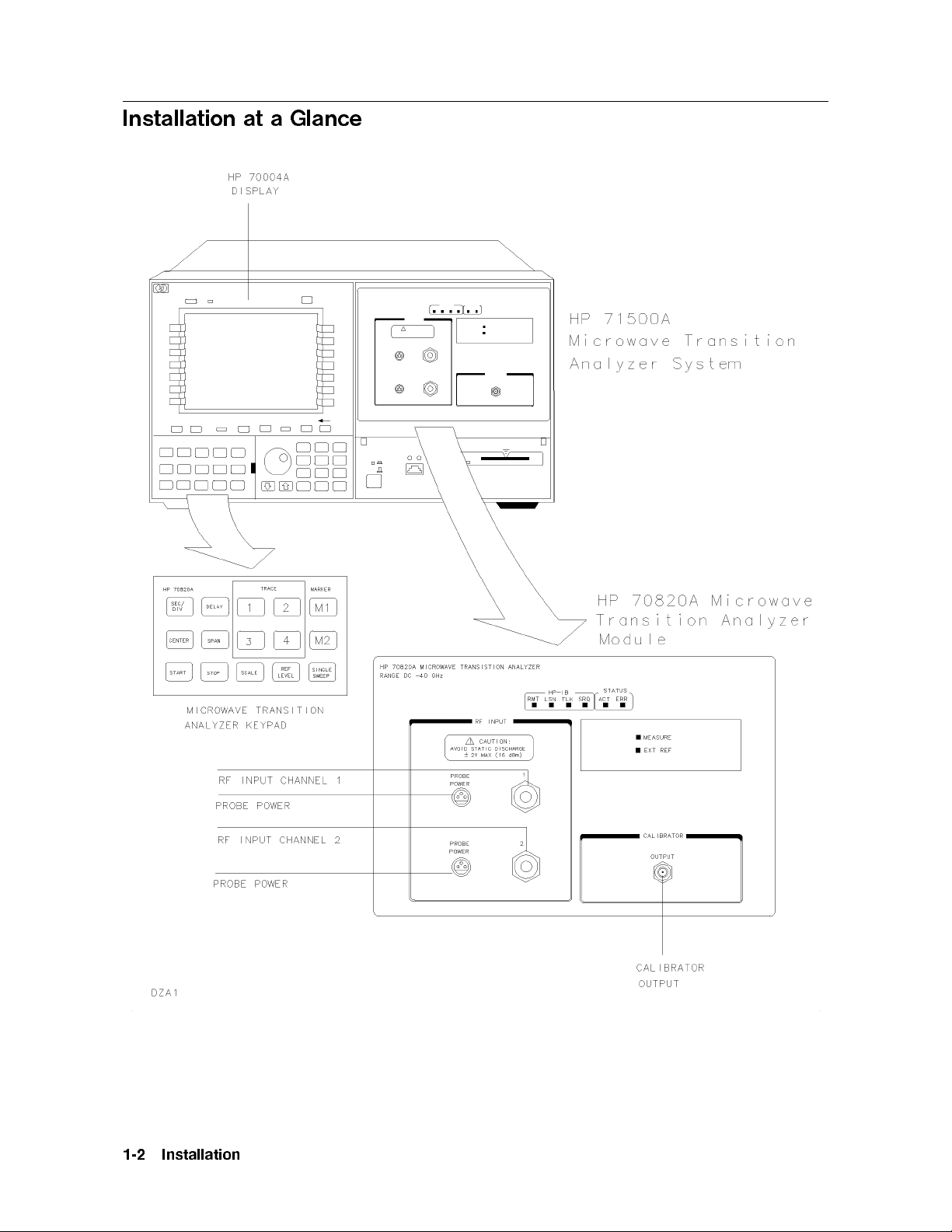
HP 71500A MicrowaveTransition Analyzer System
The HP 71500A microwave transition analyzer system is a precongured system that includes
an HP 70820A microwave transition analyzer mo dule, an HP 70004A color display/mainframe,
and a microwave transition analyzer keypad. An external power pack is also shipped with the
HP 71500A system and may b e installed if desired. Installation instructions for the external
power pack are provided in Chapter 1.
vi
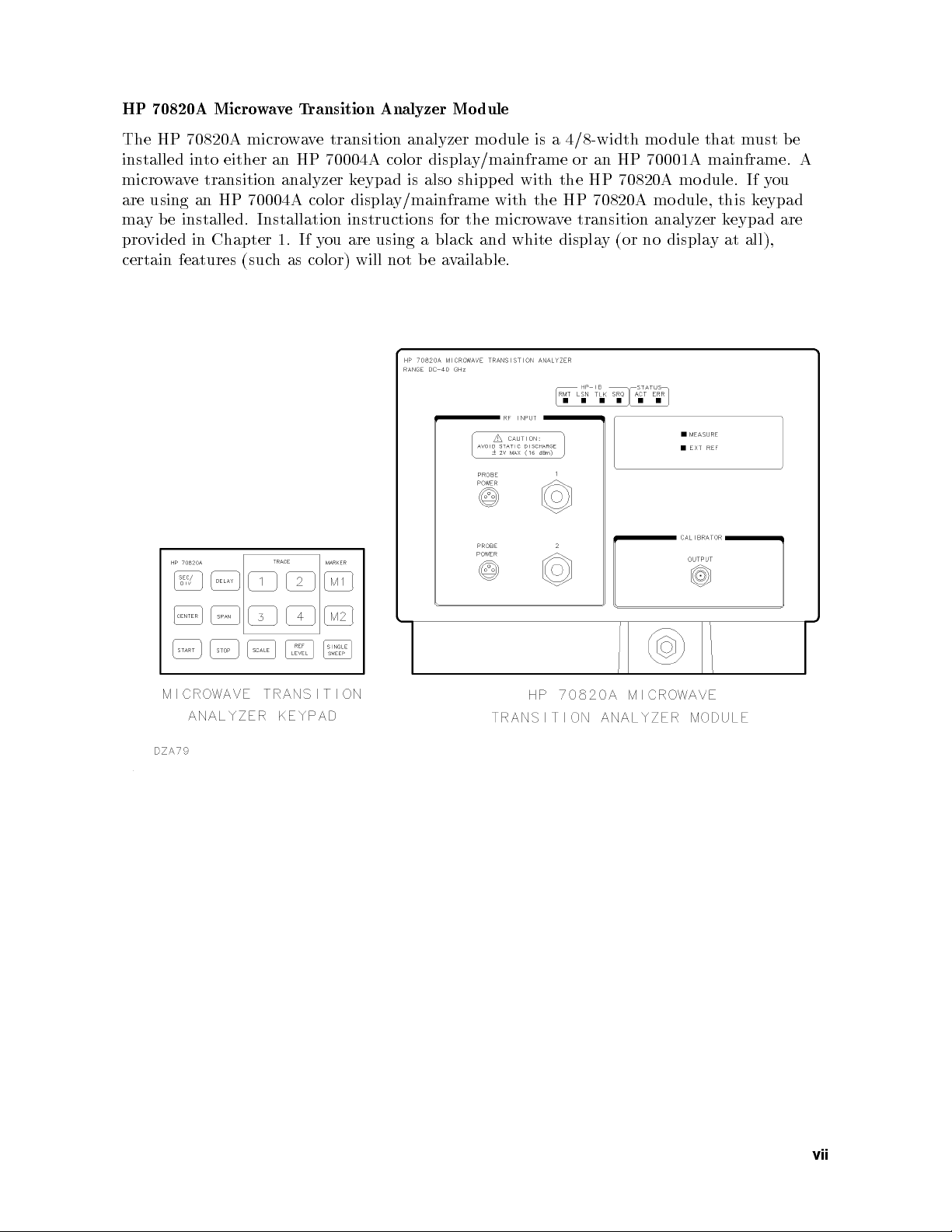
HP 70820A MicrowaveTransition Analyzer Module
The HP 70820A microwave transition analyzer mo dule is a 4/8-width mo dule that must b e
installed into either an HP 70004A color display/mainframe or an HP 70001A mainframe. A
microwave transition analyzer keypad is also shipped with the HP 70820A mo dule. If you
are using an HP 70004A color display/mainframe with the HP 70820A mo dule, this keypad
may be installed. Installation instructions for the microwave transition analyzer keypad are
provided in Chapter 1. If you are using a black and white display (or no display at all),
certain features (such as color) will not be available.
vii

Operation Verication Tests
The operation verication tests are designed to giveyou an 80 percent condence level
that the microwave transition analyzer is operating correctly and meeting its sp ecications.
Twenty one automated tests make up the operation verication tests. The op eration
verication test disks are shipped with the microwave transition analyzer. You will need
a computer system and test equipment to perform the operation verication tests on the
microwave transition analyzer.
viii

Caution
The RF INPUT circuits can be damaged by electrostatic discharge
(ESD). Therefore, avoid applying static discharges to the front-panel RF
INPUT connectors. Before connecting any coaxial cable to the connectors,
momentarily short the center and outer conductors of the cable together.
Avoid touching the front-panel RF INPUT connectors without rst touching
the frame of the instrument.
Be sure that the microwave transition analyzer is properly earth-grounded to
prevent buildup of static charge.
In This Bo ok
This book helps you install and verify the operation of the microwave transition analyzer. It
provides step-by-step instructions of the installation and verication processes.
Chapter 1 describes the HP 71500A microwave transition analyzer system, the HP
70820A microwave transition analyzer mo dule, and the steps required to
a
w
micro
the
Chapter
cedures
hapter.
c
tered
problems
of
y
Eac
problem.
pro
during
of
h
optional
eral
describ
may
help
Sev
b
A
are
correct
in
ed
encoun
e
ariet
v
iden
this
tied.
the
ducts.
pro
these
of
oth
help
of
b
analyzers
e
solv
are
problems that
analyzer's installation.
tered
ossible
p
during
installation
solutions
also
to
install
transition
2
will
transition
encoun
list
the
that
these
for
micro
could
problems
e
v
a
w
e
b
a
has
e
v
Chapter
Chapter
Note
are.
w
the
are
w
5
letters.
soft
tests
w
soft
options
details,
are
to
and
erication
running
in
ed
olv
steps
optional
eral
system.
y
safet
regarding
v
required
steps
information,
NNNNNNNNNNNNNNNNNNNN
shadow
to
the
the
3
describ
There
running
y
4
contains
and
sp
es
are
computer
our
accessories,
ecic
eral
sev
sev
and
information regarding
information
steps in
the
In this manual, normal front-panel keys are indicated in
Softkeys are indicated bya
the
the
get
that
micro
eration
op
eration
op
typeface.
will
w
eration
Op
help
transition
e
v
a
erication
v
erication
v
eration
Op
V
V
customize
to
erication
analyzer's
soft
tests.
4
boxed
ix

Contents
1. Installation
Chapter Contents . . . . . . . . . . . . . . . . . . . . . . . . . . . 1-1
Installation at a Glance . . . . . . . . . . . . . . . . . . . . . . . . 1-2
Installation at a Glance . . . . . . . . . . . . . . . . . . . . . . . 1-3
Tools Needed . . . . . . . . . . . . . . . . . . . . . . . . . . . 1-3
Installation Overview . . . . . . . . . . . . . . . . . . . . . . . 1-3
Installing the HP 71500A MicrowaveTransition Analyzer System . . . . . . 1-4
Conguring an RF Source to the MicrowaveTransition Analyzer . . . . . . 1-6
Step 1. Set Up the Frequency Reference . . . . . . . . . . . . . . . . 1-6
Step 2. Select the RF Source . . . . . . . . . . . . . . . . . . . . . 1-7
Step 3.
Step
Step
Installing
Step
Mo
Step
Mo
Step
Step
the
Optional:
ransition Analyzer
T
Optional: Installing
70004A Displa y . . . . . . . . . . . . . . . . . . . . . . . . . . 1-19
Optional: Installing the External Power Pack. . . . . . . . . . . . . . . 1-20
Optional: Mounting the System in a Rack . . . . . . . . . . . . . . . . 1-22
Optional: Connecting the MicrowaveTransition Analyzer System to Another
Display or Mainframe . . . . . . . . . . . . . . . . . . . . . . . 1-24
Optional: Displa
Optional:
Set Up
ecify
Sp
4.
ecify
Sp
5.
HP
the
Prepare
1.
. .
dule
Chec
2.
.
dule
Chec
3.
4. Install
70001A
HP
Changing
Changing
the Instrumen
HP-IB
the
HP-MSIB
the
70820A
Install
to
.
.
.
Address
the
k
.
.
.
.
System's
the
k
HP
the
Mainframe
HP-MSIB
the
Module
Micro
the
the
ying
Time
the
t Bus
arameters
P
arameters
P
T
e
v
a
w
Micro
70820A
HP
the
.
.
.
.
.
.
HP
the
of
.
.
.
.
.
.
HP-MSIB Addresses
a
w
and
and
Micro
the
or
Address
. .
T
e
v
the
the
. .
ransition
70820A
Time
.
.
.
.
.
ransition
Micro
.
.
.
70820A
.
. .
T
e
v
a
w
70004A
HP
of
.
.
Date
Date .
.
.
.
.
.
.
.
.
.
.
.
.
Analyzer
e
v
wa
.
.
.
.
w
Micro
.
.
.
.
.
ransition
Displa
HP
the
.
.
.
.
Analyzer's
.
.
.
.
.
.
.
.
.
.
.
.
.
.
.
.
Mo
ransition
T
.
.
.
T
e
v
a
.
.
.
.
.
.
Analyzer
y
70820A
.
.
.
Keypad
. .
.
.
.
.
.
.
.
. .
.
.
.
.
. .
dule
Analyzer
.
.
.
ransition
.
.
.
.
.
.
Mo
.
.
.
wa
Micro
.
.
.
to
in
.
.
.
.
.
.
.
.
.
. .
. .
.
.
.
. .
. .
.
Analyzer
.
.
.
.
.
.
in
dule
.
.
.
ve
.
.
.
the
.
.
.
. .
.
. 1-8
.
. 1-9
. .
.
.
.
.
.
.
.
.
to
. 1-16
.
.
.
HP
.
.
.
.
1-10
1-12
1-12
1-13
1-14
1-18
1-25
1-26
ve a Problem During Installation
2. If Y
ou Ha
. . . . . . . . . . . . . . . . . . . .
. . . . . . . . . . . . . . . 2-2
.
.
.
.
.
ERR
anel
.
.
.
.
.
.
ransition
T
e
the
. . . . . . . . . .
echnical Resources .
. .
.
.
.
.
.
Analyzer
.
. .
est
Self-T
.
.
ront-P
F
.
.
. . . . . . . . . . . 2-2
.
.
.
.
LED
.
.
.
.
urned
After
tents .
On
v
a
w
Chapter Con
Installation Problems
Problems Requiring Additional T
If the MicrowaveTransition Analyzer Appears to Be Dead . . . . . . . . . 2-3
If the Front-Panel LEDs Do Not Light When the MicrowaveTransition Analyzer
T
Is
Micro
the
If
Blinks
. . . . . . 2-1
.
.
.
.
.
.
.
or
Remains
.
.
Lit
.
.
.
.
.
Contents-1
.
.
2-4
2-5

If the MicrowaveTransition Analyzer Front-Panel HP-IB LEDs Remain Lit
After the Self-Test . . . . . . . . . . . . . . . . . . . . . . . . . 2-6
If Errors Are Reported on the Display. . . . . . . . . . . . . . . . . . 2-7
If the HP 70004A Display \HP-MSIB" or the HP 70001A Mainframe \I/O
CHECK" Indicator Light Remains Lit . . . . . . . . . . . . . . . . 2-8
If the HP 70001A Mainframe CURRENT Indicator Light Remains Lit . . . . 2-9
If the RF Source Does Not Go to Remote . . . . . . . . . . . . . . . . 2-10
If the MicrowaveTransition Analyzer's OVEN COLD Indicator Flashes . . . 2-12
If the MicrowaveTransition Analyzer Needs to be Returned for Service . . . 2-13
3. Operation Verication Testing
Chapter Contents . . . . . . . . . . . . . . . . . . . . . . . . . . . 3-1
Introduction . . . . . . . . . . . . . . . . . . . . . . . . . . . . . 3-2
Step 1. Set Up the Hardware for Operation Verication Testing . . . . . . 3-3
Step 2. Prepare the Computer . . . . . . . . . . . . . . . . . . . . . 3-4
Step 3. Install the Operation Verication Software Menus . . . . . . . . . 3-5
Step 4. Enter the Power Sensor Information . . . . . . . . . . . . . . . 3-6
Step 5. Decide Whether to Start Testing . . . . . . . . . . . . . . . . . 3-8
.
. .
. .
. .
.
.
.
.
. .
.
.
.
.
.
. .
.
.
.
.
Data
. .
.
.
.
.
.
.
.
.
.
.
.
.
.
.
.
.
.
.
.
. .
. .
.
.
.
.
.
.
.
.
. .
. .
.
.
6.
Step
Optional:
Optional:
Optional:
Optional:
Start
T
To
T
T
the
Edit
o
Edit the
Edit
o
Edit
o
Op
the
the
the
eration
erication
V
Storage
Mass
Parameter
Equipmen
Sensor's
er
w
o
P
Menu
Men
t
esting
T
u .
Men
.
.
.
.
u
Calibration
3-10
.
3-11
.
3-12
.
3-13
.
3-14
.
erication
Installation
4.
Chapter
duction
tro
In
w
Micro
w
Micro
Con
Coaxial
Adapters
Coaxial
dc Blocking Capacitors . . . . . . . . . . . . . . . . . . . . . . . 4-8
Bias Networks . . . . . . . . . . . . . . . . . . . . . . . . . . . 4-8
Phase-Stable Cables . . . . . . . . . . . . . . . . . . . . . . . . . 4-8
HP-MSIB Cables . . . . . . . . . . . . . . . . . . . . . . . . . . 4-9
ols
o
T
Miscellaneous
System
Serial Num
Electrostatic Disc
Reducing ESD Damage
PC Board Assem
Test Equipmen
Static-Safe Accessories . . . . . . . . . . . . . . . . . . . . . . . . 4-14
Computer Compatibility . . . . . . . . . . . . . . . . . . . . . . . . 4-15
Computer
Prin
Alternate
eration
Op
and
ten
Con
ransition
T
e
v
a
ransition
T
e
v
a
enience
v
Fixed
. .
Shorts
.
.
er Cables
w
o
P
ber Labels
Language
Compatibilit
ter
Key
erication
V
.
ts
.
. .
Kits
tten
A
. .
and
.
. .
arts
P
harge Information
t.
els
Lab
eration
Op
V
. .
.
.
.
.
.
.
.
.
.
.
.
Analyzer
Analyzer
.
.
uators
. .
ens
Op
.
.
and
.
. . . . . . . . . .
blies
. . . . . . . . . . . . .
Compatibilit
y
Soft
Options
Accessories
.
.
.
.
.
.
.
.
.
.
.
.
.
.
.
.
Supplies
.
.
.
.
. . . . . . . . . . . . .
and Electronic Comp onen
.
.
.
.
.
. .
.
Ov
are
w
Reference
.
.
.
.
.
.
.
.
.
.
.
.
.
.
.
.
.
.
.
. .
.
.
.
.
.
.
.
.
.
.
.
.
.
.
.
.
.
.
. .
.
.
.
.
.
.
.
.
.
.
.
.
.
.
.
.
.
.
. .
. .
.
.
.
.
.
.
.
.
.
.
.
.
.
.
.
. .
. .
.
.
.
.
.
.
.
.
.
.
.
.
.
.
.
.
.
.
.
. .
. .
.
. .
. .
. .
.
.
.
.
.
.
.
.
.
.
.
.
.
.
. .
. .
. .
.
.
.
.
.
.
.
.
.
.
.
.
.
. .
.
.
.
.
.
.
.
.
.
.
. .
.
.
.
.
.
.
.
.
.
.
.
.
.
.
. .
.
.
.
.
.
.
. .
.
.
.
.
.
.
.
.
.
.
. .
.
.
.
.
.
.
. . . . . . . . . . . . . . . 4-11
. . . . . . . . . . . . . . . . . . . 4-12
. . . . . . . . . . 4-12
. . . . . . . . . . 4-12
ts .
. . . . . . . . . . . . 4-13
.
. .
.
.
.
.
.
.
.
.
.
.
.
.
.
.
y
.
.
.
.
.
.
.
.
.
.
.
.
.
.
. .
.
.
.
.
.
.
.
.
.
.
.
.
.
.
.
.
.
.
.
.
.
.
. .
.
.
.
.
.
.
.
.
.
.
.
.
.
erview
.
.
.
.
.
.
.
. 4-7
.
.
. 4-9
.
.
.
4-1
4-3
4-4
4-6
4-6
4-7
4-7
4-9
4-9
4-15
4-16
4-16
4-17
Contents-2

Error Messages or Warnings Dened . . . . . . . . . . . . . . . . . 4-17
Single Tests Dened . . . . . . . . . . . . . . . . . . . . . . . . . 4-17
Printed Test Results . . . . . . . . . . . . . . . . . . . . . . . . . 4-17
Operation Verication Software Menus . . . . . . . . . . . . . . . . . 4-18
Menu Structure . . . . . . . . . . . . . . . . . . . . . . . . . . . 4-18
Edit and Command Screen Menus . . . . . . . . . . . . . . . . . . 4-19
Edit Screen Menus . . . . . . . . . . . . . . . . . . . . . . . . 4-19
Command Screen Menus . . . . . . . . . . . . . . . . . . . . . . 4-19
Cursor Keys and Menu Selections . . . . . . . . . . . . . . . . . . 4-20
Main Menu . . . . . . . . . . . . . . . . . . . . . . . . . . . . 4-21
Main MenuSoftkeys . . . . . . . . . . . . . . . . . . . . . . . . 4-21
Mass Storage Menu . . . . . . . . . . . . . . . . . . . . . . . . . 4-22
Mass Storage Menu Edit Screen . . . . . . . . . . . . . . . . . . 4-22
Mass Storage Menu Command Screen . . . . . . . . . . . . . . . . 4-23
Parameter Menu . . . . . . . . . . . . . . . . . . . . . . . . . . 4-24
Parameter Menu Edit Screen . . . . . . . . . . . . . . . . . . . . 4-24
Parameter Menu Command Screen . . . . . . . . . . . . . . . . . 4-25
Equipment Menu . . . . . . . . . . . . . . . . . . . . . . . . . . 4-26
. 4-26
.
.
.
.
.
.
.
.
.
.
.
.
.
.
.
.
.
.
Edit Screen
Equipment
Equipmen
Calibration
Edit
Men
est
T
est Men
T
Softk
u
Men
and
Error
Recommended
eration
Op
Generator
Pulse
Equipmen
Equipmen
Description
In Case
DAC Output . . . . . . . . . . . . . . . . . . . . . . . . . . . . . 4-47
Equipment. . . . . . . . . . . . . . . . . . . . . . . . . . . . . 4-47
Equipment Setup . . . . . . . . . . . . . . . . . . . . . . . . . . 4-47
Description . . . . . . . . . . . . . . . . . . . . . . . . . . . . . 4-47
In Case of Failure . . . . . . . . . . . . . . . . . . . . . . . . . . 4-47
Time Scale
Equipmen
Equipmen
Description .
In Case of F
Relative Noise Lev
Equipment.
Equipment Setup . . . . . . . . . . . . . . . . . . . . . . . . . . 4-49
Description . . . . . . . . . . . . . . . . . . . . . . . . . . . . . 4-49
Case
In
Noise
Relativ
e
Equipmen
Equipment
Description
Menu
Men
t
.
u
Command
u
Diagrams
ey
Status
est
T
erication
V
.
t
Setup .
t
.
ailure
F
of
Accuracy
.
t
Setup
t
ailure .
ailure
F
of
Lev
.
t
Setup
.
Command
u
.
Data
. .
.
Messages
(MOD
.
.
.
.
.
.
. . . .
el (CW) .
. . . . . . . . . . . . . . . .
el
.
.
.
.
.
.
. .
Screen
.
.
.
Equipmen
Descriptions
est
T
OUTPUT)
.
.
.
.
.
. .
.
.
.
.
.
.
.
.
.
.
.
.
. .
.
.
.
.
.
. . . . . . . . . . . . . . . . . . . . . . . . 4-48
. . . . . . . . . . . . .
.
.
.
.
(Pulse)
.
. .
.
.
.
.
.
.
.
.
.
.
. 4-27
. .
. .
.
.
.
.
.
.
.
.
.
.
.
Screen
.
.
.
.
.
.
.
.
.
.
.
.
.
. .
t
. .
. .
.
.
.
.
.
.
.
.
.
.
.
.
.
.
.
.
.
.
. . . . . . . . . . . . . . . . . . . . . . 4-49
.
.
.
.
.
.
.
.
.
.
.
.
.
.
.
.
4-28
.
.
.
.
.
.
.
.
.
.
. .
. .
.
.
.
.
.
. .
.
.
.
.
.
.
.
.
.
.
.
.
.
.
.
.
.
. .
.
.
.
.
.
.
.
.
.
.
.
.
.
.
.
.
.
.
.
.
.
.
.
.
. .
.
.
.
.
.
.
.
.
.
.
.
.
.
.
.
.
.
.
.
.
.
. .
.
.
.
.
.
.
.
.
.
.
.
.
.
.
.
.
.
.
.
.
.
.
.
.
.
.
.
.
.
.
.
.
.
.
.
.
.
.
.
.
.
.
. .
.
.
.
.
.
.
.
.
.
.
.
.
.
.
.
.
.
.
.
.
.
.
.
.
.
.
.
.
.
. .
.
.
.
.
.
.
.
.
.
.
.
.
.
.
.
.
.
.
.
.
. .
. .
. .
. .
.
.
.
.
.
.
.
.
.
.
. .
. .
. .
. .
.
.
.
.
.
.
.
. .
.
.
.
.
.
.
.
.
.
.
. .
.
.
.
.
.
.
.
.
.
.
.
.
.
.
. .
.
.
.
.
.
.
.
.
. .
.
.
.
.
.
.
.
.
.
.
. .
.
.
. . . . . . . . . . . . 4-48
. . . . . . . . . . . . 4-49
.
.
.
.
.
.
.
.
. .
.
.
.
.
.
.
.
.
.
.
.
.
.
.
.
.
.
.
.
.
. .
.
.
.
.
.
.
.
.
.
.
.
.
.
.
.
.
.
.
.
.
.
.
.
. .
.
.
.
.
.
.
.
.
.
.
.
.
.
.
.
.
.
.
.
.
.
.
.
.
. .
.
.
.
.
.
.
.
4-29
4-29
4-31
.
4-35
.
4-42
.
. 4-45
4-46
.
4-46
.
4-46
4-46
.
4-46
.
4-48
.
4-48
.
4-48
.
4-50
.
4-51
.
4-51
.
4-51
.
4-51
.
Contents-3

In Case of Failure . . . . . . . . . . . . . . . . . . . . . . . . . . 4-52
External Trigger (SYNC INPUT) . . . . . . . . . . . . . . . . . . . . 4-53
Equipment. . . . . . . . . . . . . . . . . . . . . . . . . . . . . 4-53
EquipmentSetup . . . . . . . . . . . . . . . . . . . . . . . . . . 4-53
Description . . . . . . . . . . . . . . . . . . . . . . . . . . . . . 4-53
In Case of Failure . . . . . . . . . . . . . . . . . . . . . . . . . . 4-53
External 10 MHz Reference . . . . . . . . . . . . . . . . . . . . . . 4-54
Equipment. . . . . . . . . . . . . . . . . . . . . . . . . . . . . 4-54
EquipmentSetup . . . . . . . . . . . . . . . . . . . . . . . . . . 4-54
Description . . . . . . . . . . . . . . . . . . . . . . . . . . . . . 4-54
In Case of Failure . . . . . . . . . . . . . . . . . . . . . . . . . . 4-54
Trigger Level . . . . . . . . . . . . . . . . . . . . . . . . . . . . . 4-55
Equipment. . . . . . . . . . . . . . . . . . . . . . . . . . . . . 4-55
EquipmentSetup . . . . . . . . . . . . . . . . . . . . . . . . . . 4-55
Description . . . . . . . . . . . . . . . . . . . . . . . . . . . . . 4-55
In Case of Failure . . . . . . . . . . . . . . . . . . . . . . . . . . 4-55
DC Accuracy . . . . . . . . . . . . . . . . . . . . . . . . . . . . . 4-56
Equipment. . . . . . . . . . . . . . . . . . . . . . . . . . . . . 4-56
Equipment
Description
Case
In
Step
IF
Equipmen
Equipmen
Description
Case
In
Harmonic
Equipmen
Equipmen
Description
Case
In
Harmonic Distortion
Equipment. . . . . . . . . . . . . . . . . . . . . . . . . . . . . 4-60
EquipmentSetup . . . . . . . . . . . . . . . . . . . . . . . . . . 4-60
Description . . . . . . . . . . . . . . . . . . . . . . . . . . . . . 4-60
In Case of Failure . . . . . . . . . . . . . . . . . . . . . . . . . . 4-60
Edge Triggered Sensitivity . . . . . . . . . . . . . . . . . . . . . . . 4-61
Equipment
Equipmen
Description
In Case of F
RF Response .
Equipment.
EquipmentSetup
Description . . . . . . . . . . . . . . . . . . . . . . . . . . . . . 4-62
In Case of Failure . . . . . . . . . . . . . . . . . . . . . . . . . . 4-63
Compression
RF
Equipmen
Equipmen
Description .
Case
In
Setup .
.
ailure
F
of
Impulse
and
t.
Setup
t
.
ailure
F
of
Distortion
.
t
Setup
t
.
ailure
F
of
.
Setup
t
.
ailure .
.
t
Setup
t
ailure
F
of
.
.
.
.
. .
.
.
. . . . . . . . . . . . . . .
. . . .
.
.
. .
. .
. .
. .
. .
.
.
.
.
.
.
.
.
.
.
.
.
.
.
.
.
.
.
.
.
.
.
.
.
. .
. .
.
.
.
.
.
.
.
.
.
.
.
.
.
.
.
.
.
.
.
.
. .
.
.
.
.
.
.
.
.
MHz)
.
.
.
.
.
.
.
.
MHz)
.
.
. .
.
.
.
.
.
.
. .
.
.
.
.
. .
.
.
.
.
.
.
.
.
.
.
.
.
.
.
.
.
.
.
.
.
.
.
. .
.
.
.
.
.
.
.
.
.
.
.
. .
.
.
.
.
.
.
.
.
.
.
.
.
.
.
.
. .
.
.
.
.
.
.
.
.
.
.
.
.
.
.
.
.
.
.
.
.
. .
.
.
.
.
.
.
.
.
.
.
.
.
.
.
.
.
.
.
.
.
.
.
.
.
.
.
.
.
.
.
.
.
.
.
.
.
.
. .
.
.
.
.
.
.
.
.
.
.
.
.
.
.
.
. .
.
.
.
.
.
.
.
.
.
.
.
.
.
.
. .
. .
. .
. .
.
.
.
.
.
.
. .
.
.
.
.
.
.
.
.
.
.
.
.
. .
.
.
.
.
.
.
.
.
.
.
. .
.
.
.
.
.
. .
.
.
.
.
.
.
.
.
. .
.
.
.
.
.
.
.
.
.
.
. .
.
. . . . . . . . . . . . . 4-62
. . . . . . . . . . 4-62
.
.
. .
.
.
.
.
.
.
.
.
.
.
.
.
.
.
.
.
.
.
.
.
.
. .
.
.
.
.
.
.
.
.
.
.
.
.
.
.
.
.
.
.
.
.
.
.
.
.
.
.
.
.
.
.
.
.
.
.
.
. .
.
.
.
.
.
.
onse
Resp
.
.
.
.
.
.
.
.
.
.
.
.
. .
10
(
.
.
.
.
.
.
.
.
. .
.
.
.
10
>
(
.
.
.
.
.
.
.
.
.
.
.
. . . . . . . . . . . . . . . . . . . . . . . . .
. . . . . . . . . . . . . . . . . . . . . . . . 4-62
. . . . . . . . . . . . . . . .
.
.
.
.
.
.
.
.
.
.
.
.
.
.
.
.
.
.
.
.
. .
.
.
.
.
.
.
.
.
. .
.
.
.
.
. .
.
.
.
.
.
.
.
.
.
.
.
.
.
.
.
.
.
.
.
.
.
. .
.
.
.
.
.
.
.
. .
.
.
.
.
. .
.
.
.
.
.
.
.
.
.
.
.
.
.
.
.
.
.
.
.
.
.
.
.
. .
. .
.
.
.
.
.
.
.
.
.
.
.
.
.
.
.
.
.
.
.
4-56
4-56
.
4-56
.
4-57
.
4-57
.
4-57
.
4-57
.
. 4-57
4-58
.
4-58
.
4-58
.
. 4-58
4-59
.
. 4-60
4-61
.
4-61
.
4-61
.
4-61
4-64
.
4-64
.
4-64
.
4-64
.
4-65
.
Contents-4

Amplitude and Phase Ratio . . . . . . . . . . . . . . . . . . . . . . 4-66
Equipment. . . . . . . . . . . . . . . . . . . . . . . . . . . . . 4-66
Equipment Setup . . . . . . . . . . . . . . . . . . . . . . . . . . 4-66
Description . . . . . . . . . . . . . . . . . . . . . . . . . . . . . 4-66
In Case of Failure . . . . . . . . . . . . . . . . . . . . . . . . . . 4-66
LowFrequency Amplitude and Phase Ratio . . . . . . . . . . . . . . . 4-67
Equipment. . . . . . . . . . . . . . . . . . . . . . . . . . . . . 4-67
Equipment Setup . . . . . . . . . . . . . . . . . . . . . . . . . . 4-67
Description . . . . . . . . . . . . . . . . . . . . . . . . . . . . . 4-67
In Case of Failure . . . . . . . . . . . . . . . . . . . . . . . . . . 4-67
Sampler Feedthrough . . . . . . . . . . . . . . . . . . . . . . . . . 4-68
Equipment. . . . . . . . . . . . . . . . . . . . . . . . . . . . . 4-68
Equipment Setup . . . . . . . . . . . . . . . . . . . . . . . . . . 4-68
Description . . . . . . . . . . . . . . . . . . . . . . . . . . . . . 4-68
In Case of Failure . . . . . . . . . . . . . . . . . . . . . . . . . . 4-68
IF Isolation . . . . . . . . . . . . . . . . . . . . . . . . . . . . . 4-69
Equipment. . . . . . . . . . . . . . . . . . . . . . . . . . . . . 4-69
Equipment Setup . . . . . . . . . . . . . . . . . . . . . . . . . . 4-69
. 4-69
. .
. .
.
.
.
.
.
.
.
.
.
.
.
.
.
.
.
.
.
.
.
. .
Description .
of
Case
In
Crosstalk
Input
Equipmen
Equipmen
Description
of
Case
In
Amplitude
Equipmen
Equipmen
Description
of F
Case
In
Alternativ
60 MHz
110 kHz Low-Pass Filter . . . . . . . . . . . . . . . . . . . . . . . . 4-77
e
Lo
. .
ailure
F
Isolation
.
.
t
t Setup
.
.
ailure
F
Accuracy
.
.
t
Setup
t
.
.
ailure .
Using
to
ass
w-P
.
.
.
.
.
.
.
ersus
v
.
.
.
.
.
a
Filter
.
.
.
. .
.
.
.
.
.
.
.
.
.
.
.
.
.
.
Matc
.
.
.
.
.
. .
.
.
.
.
.
.
Input
.
.
.
.
.
.
.
.
hed
.
.
.
.
.
.
.
.
.
.
. .
.
Set
.
.
.
.
.
.
.
Po
.
.
.
.
.
.
.
.
.
. .
w
.
.
. .
.
of
.
.
.
.
.
.
.
.
.
.
.
.
Lev
er
.
.
.
.
.
.
.
Cables
.
.
4-70
.
.
.
.
.
. .
. .
. .
. .
.
.
.
4-71
.
.
.
.
.
.
.
.
.
.
. .
. .
.
.
4-71
.
.
.
.
.
.
.
.
.
.
.
.
.
.
.
.
4-71
.
. .
. .
.
.
.
.
.
.
.
.
.
.
.
4-71
.
.
.
.
.
.
.
.
.
. .
.
.
.
.
.
4-72
.
.
.
.
.
.
.
.
.
.
.
.
.
.
.
.
4-73
.
.
.
.
.
.
.
.
.
.
.
.
.
.
el
4-73
.
.
.
.
.
.
. .
.
.
.
.
.
.
.
.
4-73
.
.
.
.
.
.
.
.
.
.
.
. .
.
.
.
4-73
.
.
.
.
.
.
.
.
.
.
.
.
.
.
.
.
. .
. .
.
.
.
.
.
.
.
.
.
.
.
.
. .
. .
.
.
.
.
. .
.
. .
. .
. .
.
.
esting
T
for
.
.
.
.
.
4-73
4-74
4-75
.
Index
Contents-5

Figures
2-1. Line Voltage Selector . . . . . . . . . . . . . . . . . . . . . . . . 2-3
2-2. Line Fuse Removal and Replacement . . . . . . . . . . . . . . . . . 2-3
2-3. Packaging Materials for the HP 70820A Module . . . . . . . . . . . . 2-14
2-4. Packaging Materials for the HP 71500A System . . . . . . . . . . . . . 2-15
4-1. Module Serial-Number Label . . . . . . . . . . . . . . . . . . . . . 4-11
4-2. Static-Safe Workstation . . . . . . . . . . . . . . . . . . . . . . . 4-12
4-3. Main MenuSoftkeys . . . . . . . . . . . . . . . . . . . . . . . . . 4-31
4-4. Mass Storage Menu and Parameter Menu Softkeys . . . . . . . . . . . 4-32
4-5. EquipmentMenu Softkeys . . . . . . . . . . . . . . . . . . . . . . 4-33
4-6. Test Menu Softkeys . . . . . . . . . . . . . . . . . . . . . . . . . 4-34
.
.
.
.
.
.
. .
.
.
.
.
.
.
.
.
.
.
.
.
.
.
. .
.
.
. .
4-7.
4-8.
ables
T
2-1.
4-1.
4-2.
4-3.
4-4.
4-5. 110
w-P
Lo
MHz
60
w
er
Low-P
ac
Cables
Accessories
k
110 kHz
Hewlett-P
o
P
Static-Safe
Recommended
kHz
Low-P
w-P
Lo
60 MHz
Filter Sc
ass
ass Filter
Sales
ard
.
.
.
est
T
ass Filter
Filter
ass
hematic Diagram
hematic
Sc
Service
and
.
.
.
.
.
.
.
Equipmen
Parts
arts
P
.
.
t
List
List
Diagram
Oces
.
.
.
.
.
.
. .
.
.
.
.
. .
.
.
. .
.
.
.
.
.
and Comp
Comp
and
.
.
.
.
.
.
.
.
.
.
.
.
. .
.
.
.
.
.
.
.
.
.
.
.
.
.
.
onent
onen
.
.
.
.
. .
.
.
.
.
. .
.
t
.
.
. .
.
.
Lo
Lo
.
.
.
.
. .
cation
cation
.
.
.
.
.
4-75
.
4-77
.
. 2-16
4-10
.
4-14
.
4-43
.
4-76
4-78
.
Contents-6

Installation
Chapter Contents
1
Installation at a Glance
Installing the HP 71500A MicrowaveTransition Analyzer System
Conguring an RF Source to the MicrowaveTransition Analyzer
Step 1. Set Up the Frequency Reference
Step 2. Select the RF Source
the
Up
Set
3.
Step
the
ecify
Sp
4.
Step
the
ecify
Sp
5.
Step
Prepare
e
v
a
w
Chec
e
v
a
w
Chec
Install
HP 70001A
the
Changing
e
v
a
w
Installing
Displa
Changing
HP 70820A
ransition
T
the
k
ransition
T
the
k
the
ransition
T
70004A Displa
ying
Installing the
1.
Step
Micro
2.
Step
Micro
3.
Step
4.
Step
to
in
Optional:
Micro
Optional:
the HP
into
Optional: Installing the External Power Pack
Optional: Mounting the System in a Rack
Optional: Connecting the MicrowaveTransition Analyzer System
to Another Display or Mainframe
Optional:
Optional:
:::::::::::: ::::::::::::::: ::::::::::::::: ::::::::::::::
::::::::::::: ::::::::::::::: :::::::::
::::::::::: ::::::::::::::: ::::::::::::::: :::::::
:
:
:
:
:
:
:
:
:
:
:
:
:
:
:
:
:
:
:
:
:
:
:
:
:
Bus
Instrumen
HP-IB
HP-MSIB P
Install
to
Address
System's
70820A
HP
Mainframe or
HP-MSIB
the
Analyzer
Micro
the
Time
the
Time
the
t
arameters
P
w
Micro
HP
the
Analyzer
of the
Analyzer
HP-MSIB
av
w
:
:
y
and
and the
:
:
:
:
:
:
:
:
:
:
::
::
::
::
:
:
:
:
:
:
:
:
:
:
:
:
:
:
:
:
:
::
arameters
ransition
T
e
v
a
70820A
dule
Mo
HP
dule
Mo
w
Micro
the
Address
dule
Mo
ransition Analyzer's
eT
:
:
:
:
:
:
:
::::::::::::: ::::::::::::::: :::::::::::::::
Date
the
Date
::
:
dule
:
:
:
:
:
:
:
:
:
Displa
70820A
:
:
:
::
::
:
:
:
:
::
:
:
:
Mo
:
:
:
:
:
:
:
:
:
::
:
:
:
::
:
:
:
:
:
:
Analyzer
y
:
:
:
:
:
:
:
Keypad
:
:
:
:
:
:
:
::
:
:
:
:
:
:
:
:
:
:
:
:
:
:
:
:
:
Analyzer
:
:
:
::
:
:
:
70820A
:
:
:
:
:
:
:
:
Addresses
ransition
eT
v
a
70004A
HP
HP
the
of
:
::
::
:
:
:
:
::
::
:
:
:
:
:
:
:
::::::::::::::: ::::::::::::::: :::
::::::::::::::: ::::::::::::::: ::::::
:
::
:
:
:
:
:
:
:
:
:
:
::::::::::::: ::
:::::::::::::::
:
:
:
:
:
:
:
:
:
:
:
::
::
:
:
:
:
:
:
:
::
::
::
::
:
:
:
:
:
:
:
:
:
:
:
:
:
:
::
:
:
:
:
:
:
:
:
:
:
:
:
:
:
:
:
:
:
:
:
:
:
:
:
:
:
:
:
:
:
:
:
:
dule
Mo
:
:
:
:
:
:
:
:
:
:
:
:
::
:
:
:
:
:
:
:
:
:
::
:
:
:
:
:
:
:
:
:
::
:
:
:
:
:
:
:
:
:
:
:
:
:
:
:
:
::
:
:
:
:
::
::
::
:
1-2
1-4
1-6
1-6
1-7
1-8
:
:
:
:
:
1-9
:
:
::
1-10
:
:
:
:
1-12
::
:
:
1-12
:
:
:
:
1-13
:
:
:
:
1-14
:
:
:
:
1-16
:
:
:
:
1-18
:
:
:
:
1-19
::
1-20
1-22
1-24
1-25
:
:
:
:
1-26
:
:
:
:
Installation
1-1
Installation at a Glance
1-2
Installation
Installation at a Glance
The microwave transition analyzer is available as part of a precongured system or as a
separate module that you can add to an existing system. The precongured system, the
HP 71500A microwave transition analyzer system includes the HP 70820A microwave
transition analyzer mo dule installed in the HP 70004A Display. The HP 70820A microwave
transition analyzer mo dule may be installed in an existing HP 70004A Display or it maybe
installed in an HP 70001A Mainframe using another display or no display at all. Both models
include a custom microwave transition analyzer keypad for use with the HP 70004A Display.
Tools Needed
No to ols are required for the basic installation of the HP 71500A system. However, the
HP 70820A mo dule installation and the optional installation steps require these to ols:
An 8 mm hex ball driver for installing and removing mo dules.
hes.
and
for
eypad
k
switc
in
an
nonconductive
A
ozidriv
P
small
A
ozidriv
P
large
A
the
ting
moun
at-blade
small
A
70004A
HP
microw
displa
suc
ylus,
st
screwdriv
screwdriv
e
av
screwdriv
.
y
a
as
h
installing
for
er
installing
for
er
transition
for
er
othpic
to
analyzer
installing
similar
or
k
optional
the
the optional
system
the
in
micro
ject,
ob
terlo
in
external p
equipmen
an
to
transition
e
v
a
w
for
c
k
setting
kit.
er pac
ow
address
k
k.
rac
t
analyzer
erview
Installation
HP
The
system
Optional
system,
time
Ov
71500A
preassem
is
installation
connecting the
included
also
are
micro
bled
e
v
a
w
the
at
steps,
system to
and
transition
factory
as
h
suc
another displa
e
b
y
ma
analyzer
installation
and
installing
as
used
system
external p
an
y
desired.
installation
requires
mainframe,
or
After
is
minimal
k,
pac
er
ow
and
installation,
straigh
time
k
rac
setting
RF
an
tforw
to
moun
the
source
The
ard.
complete.
the
ting
and
date
ma
be
y
congured to the HP 71500A system.
The HP 70820A microwave transition analyzer mo dule installation is more involved. The
HP 70820A mo dule installation pro cedures include several required and several optional steps.
The required installation steps include:
dule.
of
mo
the
70820A mo
HP
dule.
Preparing
king
Chec
install the
to
HP-MSIB
the
70820A
HP
address
Checking the system's HP-MSIB addresses.
Installing the
HP 70820A mo dule in
to a displa
Conguring an RF source to the microw
ave transition analyzer.
y or a mainframe.
The optional installation steps for the HP 70820A mo dule include:
Changing the HP-MSIB address of the HP 70820A mo dule.
Installing the microwave transition analyzer's keypad into the HP 70004A display.
k.
pac
er
w
o
micro
w
hanging
p
w
e
v
a
the
transition
e
v
a
transition
and
time
analyzer
analyzer
date.
system.
system
another
to
displa
or
y
mainframe.
Installing
k moun
Rac
Connecting
ying
Displa
the
ting
the
and
external
the
micro
c
Installation
1-3

Installing the HP 71500A Microwave Transition Analyzer System
1
Unpack the HP 71500A microwave transition
analyzer system from its shipping containers.
Inspect the HP 71500A thoroughly to ensure that
it was not damaged during shipment.
2
Set the line-voltage selector to the voltage
corresponding to the power source used. The
line-voltage selector is located on the left side of
the microwave transition analyzer, near the front.
Caution
Before
turning
this
instrumen
t
the
sure
e
mak
on,
line-voltage selector is set to the voltage of the ac
power source:
115 V p osition for 90 to 132 Vac line input
voltages at 50, 60, or 400 Hz
input
line
Vac
264
to
198
at
50
or
for
60
Hz
230
oltages
v
V
osition
p
Connect
3
w
micro
connect
oltage.
v
line
transition
e
v
a
the
the
other
ac
o
p
analyzer
end
the
of
rear
the
to
cord
er
w
Then
the
to
cord
er
w
o
of
the
system.
p
ac
1-4
Installation

4
Press the microwave transition analyzer's
front-panel
ou
y
If
er
w
o
p
connecting
mainframe,
hanging
c
wing
follo
\Optional:
on
\Optional:
page
\Optional:
ransition
T
an
w
pac
page
1-22
LINE
instructions
t
moun
k,
system
the
displa
date
the
optional
Installing
1-20
Mounting
Connecting
Analyzer
switch to turn the system on.
external
for
the
ting
another
to
the
ying
the
and
installation
the
the
the
System
installing
system
date
time,
steps:
External
System
Micro
to
an
k,
rac
a
in
or
y
displa
time,
the
and
the
to
refer
er
w
o
P
Rac
a
in
e
av
w
Another Displa
or Mainframe" on page 1-24
\Optional: Displaying the Time and the Date"
on page 1-25
P
k"
5
Press the
NNNNNNNNNNNNNNNNNNNNNNNNNNNNN
NEXT INSTR
ou
y
If
w
micro
\Conguring
or
ransition
T
An
RF
micro
k"
ac
from
Without
on
micro
measuremen
ou
y
If
to
refer
y
Transition Analyzer Quick Start Guide
w
a
are
an
e
v
source
a
w
our
y
wa
the
t
ready
4
DISPLAY
softkey.
congure
to
transition
RF
an
Analyzer"
should
transition
e
v
w
micro
conguring
transition
e
v
ts will
to
71500A/HP
HP
5
key. Press the
analyzer,
Source
on
e
v
a
the
e
b
start
started.
RF
an
refer
the
to
1-6.
page
congured
e
b
analyzer
transition
source
RF
analyzer,
limited.
making
70820A
source
to
to
w
Micro
to
the
get
to
analyzer.
the
to
our
y
measuremen
Micr
to get
our
y
e
v
a
our
y
most
owave
ts,
\Optional: Changing the Time and the Date"
1-26
page
on
Installation
1-5

Configuring an RF Source to the Microwave Transition Analyzer
Step 1. Set Up the Frequency Reference
The microwave transition analyzer and RF source
should use the same frequency standard. The
microwave transition analyzer can be congured
so that either the RF source's 10 MHz reference or
the HP 70820A module's 10 MHz reference may
be used as the frequency standard.
The HP 70820A module's 10 MHz reference is not
kept warm when the microwave transition
analyzer's power is turned o unless an external
power pack is installed. The HP 70820A module's
10 MHz reference requires a minimum of
20 minutes to warm-up when the mo dule is
powered up.
MHz
w
you
If
reference
and
1
step
w
ou
y
If
MHz
10
erform
p
Connect
2
70820A
HP
OUTPUT
use
to
t
an
as the
step
use
to
t
an
reference
step
only
the
mo
the
to
the
frequency
this
on
3
the
the
as
and
2
MHz
10
10
dule's
source's
RF
source's
RF
standard,
page.
70820A
HP
frequency
step
reference
MHz
10
erform
p
dule's
mo
standard,
page.
this
on
3
from
cable
REFERENCE
reference
MHz
10
only
the
input.
1
Connect the 10 MHz reference cable from the
RF source's 10 MHz reference output to the
HP 70820A mo dule's
INPUT
3
softk
EXT
source's
standard
using
as
.Continue at step 3 on this page.
4
the
Press
ey
is
the
the
.
frequency
MENU
Press the
underlined
MHz
10
til
un
or
70820A
HP
10 MHz REFERENCE
5
N
N
N
N
N
N
N
N
N
N
N
N
N
N
MHz
10
ou
y
if
reference
is
INT
mo
N
N
N
N
N
N
are
as
underlined
dule's
N
N
N
N
N
N
N
N
N
NN
N
N
N
N
INT|EXT
using
frequency
the
10
N
press
Then
.
ey
k
standard.
N
N
N
N
softkey
the
if
MHz
N
N
the
Config
RF
ou
y
reference
N
N
N
are
N
N
N
un
N
N
N
N
N
N
N
N
N
N
til
1-6
Installation
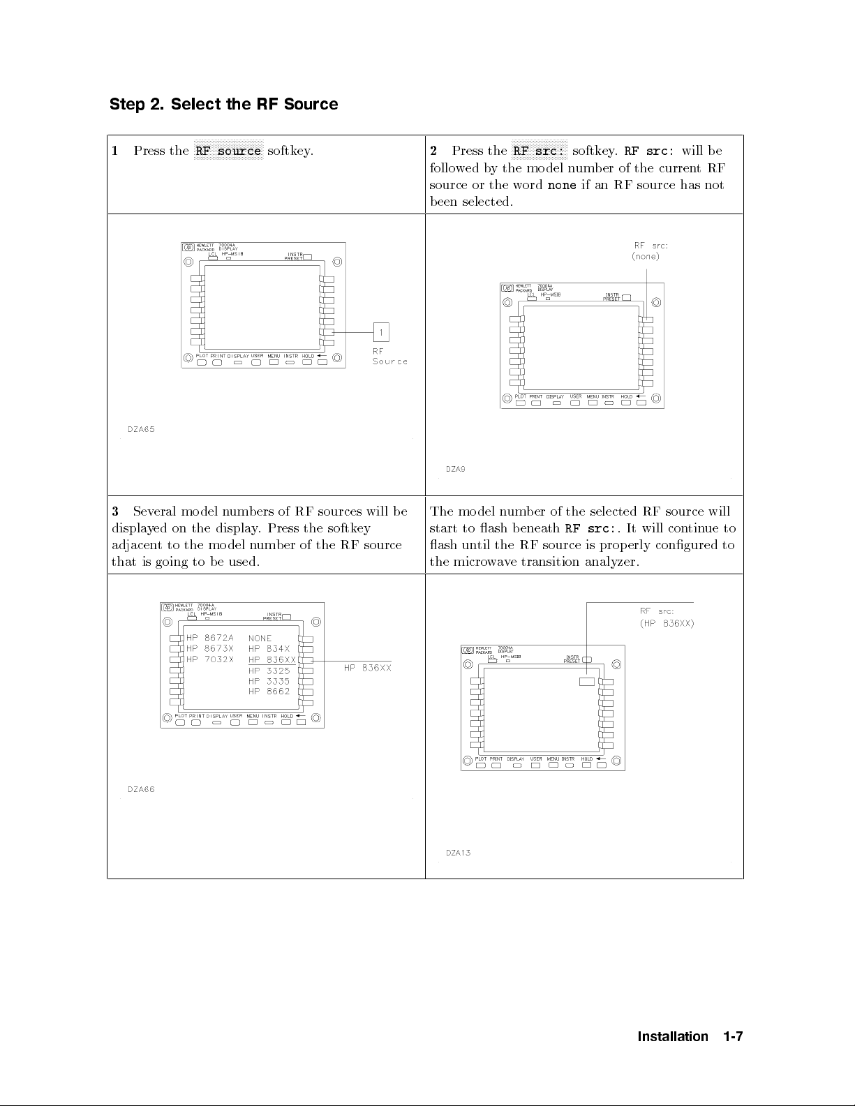
Step 2. Select the RF Source
1
Press the
Sev
3
displa
adjacen
is
that
eral
ed
y
t
going
NNNNNNNNNNNNNNNNNNNNNNNNNN
RF source
del
mo
the
on
the
to
to
n
displa
del
mo
e
b
um
used.
b
n
y
ers
.
um
softkey.
RF
of
Press
of
er
b
sources
the
the
softk
RF
will
ey
source
2
Press the
RF src:
softkey.
RF src:
followed by the model number of the currentRF
NNNNNNNNNNNNNNNNNNNNN
source or the word
none
if an RF source has not
been selected.
e
b
The
start
ash
the
del
mo
to
til
un
micro
ash
w
n
the
v
a
um
b
e
er
b
eneath
source
RF
transition
of
the
src:
RF
is
analyzer.
selected
prop
.
It
erly
RF
will
will be
source
ue
tin
con
congured
will
to
to
Installation
1-7

Step 3. Set Up the Instrument Bus
The microwave transition analyzer must use an
instrument bus to control the RF source. Either
an HP-IB or an HP-MSIB is used, depending on
the type of bus that the RF source is equipped for.
For RF sources that are equipped with both an
HP-IB or an HP-MSIB, either bus may be used.
If you want to control the RF source using the
HP-IB, perform step 1 and step 2 on this page.
If you want to control the RF source using the
HP-MSIB, perform step 1 and step 3 on this page.
panel
rear
the
from
micro
rear
tin
panel
panel
at
ue
on
cable
a
w
of
the
\Step
page
transition
e
v
the
HP-IB
the
of
1-9.
RF
4.
source.
cable
displa
ecify the
Sp
analyzer
(Do
HP-IB
to
the
or
y
2
Connect
HP 70820A
of the
the
module
not mistak
to
enly
connector on
mainframe.)
arameters"
HP-IB
P
the HP-IB
rear
connect
the
Con
1
Press the
HP-IB HP-MSIB
softkey until the
bus that is being used is underlined. The bus that
is underlined is selected.
rear
the
from
NNNNNNNNNNNNNNNNNNNNNNNNNNNNNNNNNNNNNNNN
transition
e
v
the
to
y
e
b
HP-MSIB
cables
rear
mainframe.
or
routed
analyzer's
RF
the
of
The
Con
serially
.
arameters" on
P
source
tin
ue
3
Connect
panel of
display
or the
the HP-MSIB
the micro
mainframe
or
source's
RF
HP-MSIB cables
ecify
Sp
5.
\Step
at
1-10.
page
w
displa
ust
m
a
the
1-8
Installation

Step 4. Specify the HP-IB Parameters
1
Determine the HP-IB address of the RF
source. Refer to RF source's documentation for
information regarding its HP-IB address.
erly
prop
is
source
RF
the
that
erify
V
3
erly
prop
congured.
congured,
the
ears
an
mo
b
ash.
erform
p
and
app
longer
When
micro
the
instrumen
n
del
eneath
um
RF
the
b
RF
a
w
preset
t
of
er
src:
e
v
source
the
on
is
transition
the
on
source
RF
displa
the
analyzer
source
RF
that
will
y
no
Press the
source's two-digit HP-IB address using the
numeric keypad. Press the
y
If
4
measuremen
will
71500A/HP
HP
nalyzer
A
ou
are
Quick
HP-IB ADDR
to
ready
to
refer
ts,
70820A
Start
softkey.Enter the RF
NNNNNNNNNNNNNNNN
ENTER
making
start
the
Micr
to
Guide
2
NNNNNNNNNNNNNNNNNNNNNNNNNNNNN
owave
get
softkey.
ansition
r
T
started.
Installation
1-9
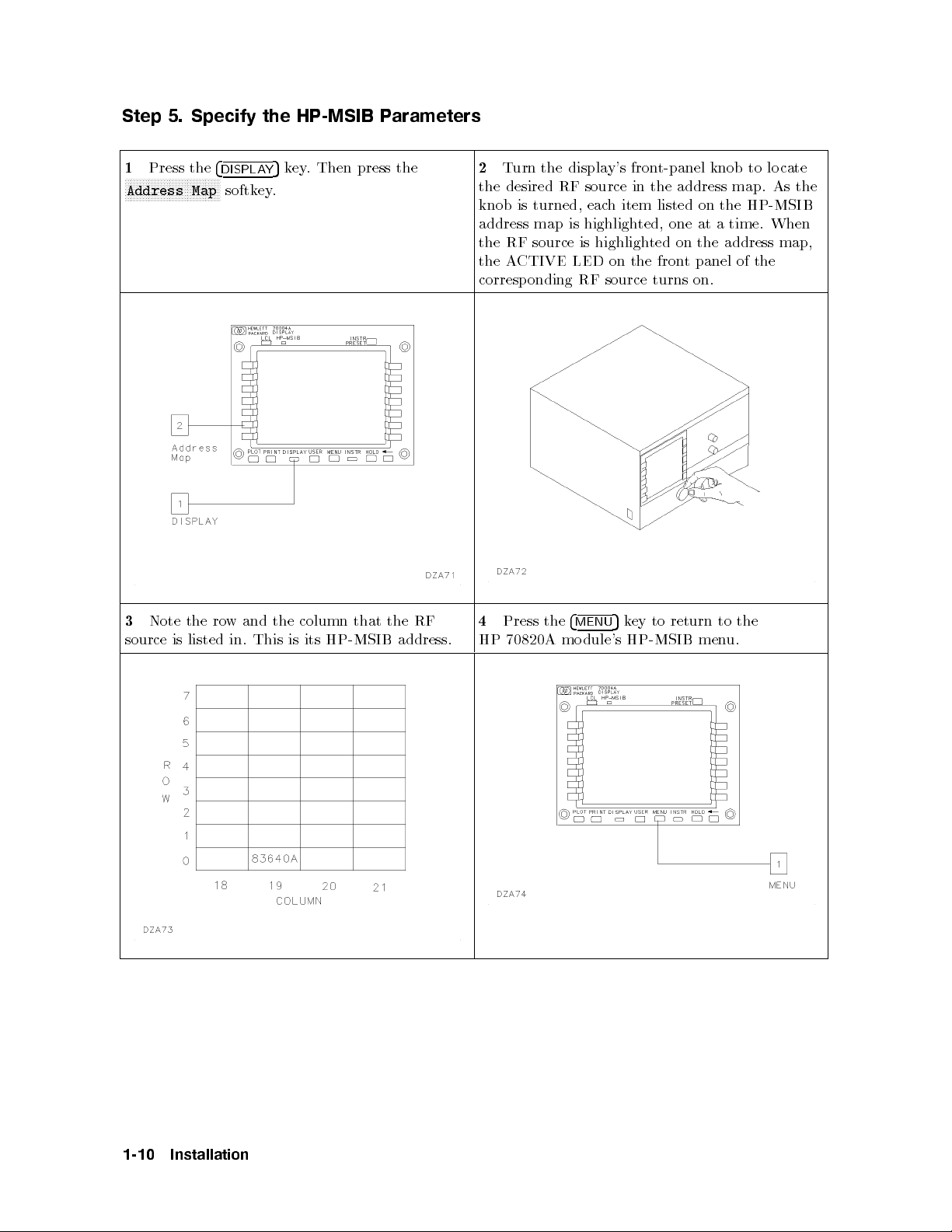
Step 5. Specify the HP-MSIB Parameters
1
Press the
NNNNNNNNNNNNNNNNNNNNNNNNNNNNNNNN
Address Map
4
DISPLAY
softkey.
5
key. Then press the
2
Turn the display's front-panel knob to lo cate
the desired RF source in the address map. As the
knob is turned, each item listed on the HP-MSIB
address map is highlighted, one at a time. When
the RF source is highlighted on the address map,
the ACTIVE LED on the front panel of the
corresponding RF source turns on.
Note
3
source
is
the
listed
ro
w
in.
and
This
the
column
its
is
that
HP-MSIB
RF
the
address.
4
HP
Press
70820A
the
4
mo
MENU
dule's
ey
k
5
HP-MSIB
to
return
men
to
the
u.
1-10
Installation
Press the
number of the RF source's HP-MSIB rownumber
using the numeric keypad. Press the
erify
7
V
congured. When
congured, the
perform
and the
appears
ash.
longer
HP-MSIB ROW
that
instrumen
an
del
mo
eneath
b
the
micro
um
n
RF
RF
the
b
source
RF
a
w
preset
t
of
er
src:
softkey.Enter the
prop
is
is
transition
the
on
source
RF
displa
the
e
v
source
the
on
NNNNNNNNNNNNNNNN
ENTER
erly
erly
prop
analyzer
RF
y
source
that
will
key.
will
no
5
NNNNNNNNNNNNNNNNNNNNNNNNNNNNNNNN
6
Press the
HP-MSIB COLUMN
softkey.Enter the
number of the RF source's HP-MSIB column
number using the numeric keypad. Press the
NNNNNNNNNNNNNNNN
NNNNNNNNNNNNNNNNNNNNNNNNNNNNNNNNNNNNNNNN
ENTER
8
measurements,
HP 71500A/HP
Analyzer
If
softkey.
ou
y
Quick
are
ready
refer
70820A
Start
to
to
Guide
start
the
Micr
making
owave
get
to
ansition
r
T
started.
Installation
1-11

Installing the HP 70820A Microwave Transition Analyzer Module
Step 1. Prepare to Install the HP 70820A Microwave Transition Analyzer Module
1
Unpack the HP 70820A microwave transition
analyzer mo dule from its shipping containers.
2
Inspect the HP 70820A thoroughly to ensure
that it was not damaged during shipment.
Install
3
using
e
b
will
appropriate
the
to
instructions.
mainframe
the
with
or
70820A
HP
the
installation
the
displa
man
mo
ual
that
y
dule.
for
ou
y
Refer
HP
The
4
It
dule.
mo
installation.
mainframe
the
from
necessary
70820A
requires
Remo
slots.
dule
mo
four
previously
e
v
displa
or
is
adjacen
y
4/8-width
a
empt
t,
installed
en
op
to
y
the
slots
mo
for
dules
1-12
Installation
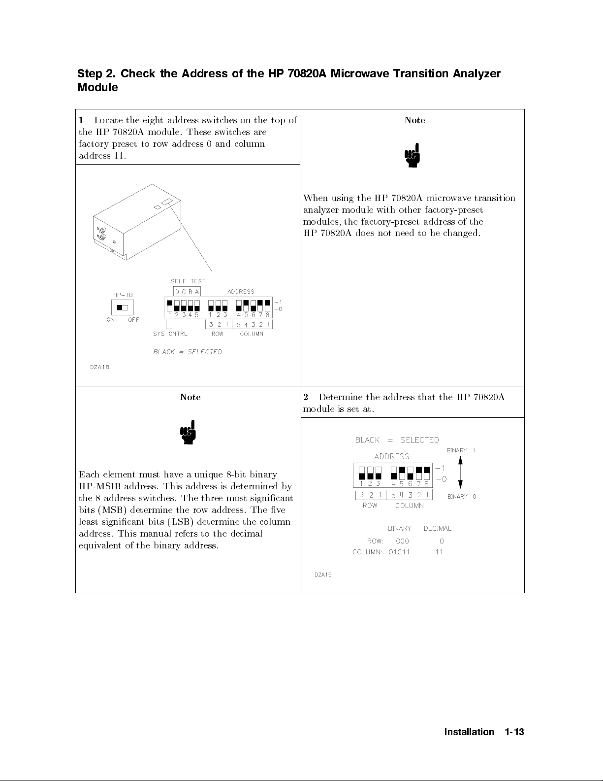
Step 2. Check the Address of the HP 70820A Microwave Transition Analyzer
Module
1
Locate the eight address switches on the top of
Note
the HP 70820A module. These switches are
factory preset to row address 0 and column
address 11.
When using the HP 70820A microwave transition
analyzer mo dule with other factory-preset
modules, the factory-preset address of the
HP 70820A do es not need to b e changed.
Note
binary
h elemen
Eac
tm
ust ha
unique
a
e
v
8-bit
HP-MSIB address. This address is determined by
the 8 address switches. The three most signicant
bits (MSB) determine the row address. The ve
least signicant bits (LSB) determine the column
address. This manual refers to the decimal
binary address.
the
of
t
alen
equiv
2
Determine
module
address
the
at.
set
is
that
70820A
HP
the
Installation
1-13

Step 3. Check the System's HP-MSIB Addresses
1
Press the
or the displayon.
LINE
switch to turn the mainframe
If the display b eing used is an HP 70004A,
continue at step 2 on this page.
If the display b eing used is an HP 70205A,
continue at step 3 on this page.
If the display b eing used is an HP 70206A,
continue at step 4 of this pro cedure lo cated on the
next page.
the
press
2
F
4
DISPLA
softk
map.
the
on
or the
5
Y
to
ey
Con
next
HP 70004A
then
,
ey
k
y
displa
at
ue
tin
page.
Display
press
the system's
5
step
,
N
N
N
N
N
N
N
N
N
N
N
N
N
N
the
Address
HP-MSIB address
pro
this
of
N
N
N
N
NN
NN
N
N
N
Map
cedure
or the
3
N
N
N
N
N
N
N
cated
lo
the
softk
map.
on
F
4
the
DSP
ey
Con
5
to
next
HP 70205A
then
,
ey
k
y
displa
at
ue
tin
page.
Graphics Displa
the
press
the system's
this
of
5
step
N
address
map
press
,
y
N
N
N
N
N
N
N
N
N
N
N
NN
NN
N
N
N
N
N
N
N
N
N
N
N
N
N
N
N
N
HP-MSIB address
pro
cedure
lo
cated
1-14
Installation
 Loading...