

Page 1

About this Manual
We’ve added this manual to the Agilent website in an effort to help you support
your product. This manual is the best copy we could find; it may be incomplete
or contain dated information. If we find a more recent copy in the future, we will
add it to the Agilent website.
Support for Your Product
Agilent no longer sells or supports this product. Our service centers may be able
to perform calibration if no repair parts are needed, but no other support from
Agilent is available. You will find any other available product information on the
Agilent Test & Measurement website, www.tm.agilent.com.
HP References in this Manual
This manual may contain references to HP or Hewlett-Packard. Please note that
Hewlett-Packard's former test and measurement, semiconductor products and
chemical analysis businesses are now part of Agilent Technologies. We have
made no changes to this manual copy. In other documentation, to reduce
potential confusion, the only change to product numbers and names has been in
the company name prefix: where a product number/name was HP XXXX the
current name/number is now Agilent XXXX. For example, model number
HP8648A is now model number Agilent 8648A.
Page 2

Installation, Verification, Operation,
Programming, and Service Manual
HP 70590A Options H62 and H72
Test Module Adapters
ABCDE
70590-90023
No.
Part
HP
Printed
in
USA
No
ember
v
1989
Page 3

Notice
The information contained in this do cument is sub ject to change without notice.
Hewlett-Packard makes no warrantyofany kind with regard to this material, including,
but not limited to, the implied warranties of merchantability and tness for a particular
purpose. Hewlett-Packard shall not be liable for errors contained herein or for incidental or
consequential damages in connection with the furnishing, performance, or use of this material.
Restricted Rights Legend.
Use, duplication, or disclosure by the U.S. Government is sub ject to restrictions as set forth
in subparagraph (c) (1) (ii) of the Rights in Technical Data and Computer Software clause
at DFARS 252.227-7013 for DOD agencies, and subparagraphs (c) (1) and (c) (2) of the
Commercial Computer Software Restricted Rights clause at FAR 52.227-19 for other agencies.
c
Copyright Hewlett-Packard Company 1989
All Righ
ermission
p
oun
F
1400
Reserv
ts
is
taingro
Repro
ed.
prohibited,
arkw
P
e
v
duction,
except
Santa
,
y
a
adaptation,
allo
as
Rosa,
written
prior
ws.
yrigh
USA
without
la
t
translation
or
cop
under
ed
w
CA
the
95403-1799,
Page 4

Certification
Hewlett-Packard Company certies that this product met its published specications at the
time of shipment from the factory. Hewlett-Packard further certies that its calibration
measurements are traceable to the United States National Institute of Standards and
Technology, to the extent allowed by the Institute's calibration facility, and to the calibration
facilities of other International Standards Organization members.
Warranty
This Hewlett-Packard instrument pro duct is warranted against defects in material and
workmanship for a perio d of one year from date of shipment. During the warranty period,
Hewlett-Packard Company will, at its option, either repair or replace products whichproveto
be defective.
For warranty service or repair, this pro duct must be returned to a service facility designated
and
ard
k
Buy
to
by
when
to
ac
w
Ho
er.
Hewlett-P
Hewlett-Pac
erly installed
prop
instrumen
the
of
ev
er,
ac
k
Buy
ard
k
ard
er
for
on
or
t,
Hewlett-P
y
b
Hewlett-P
pay
shall
another
from
Hewlett-P
with
use
instrumen
that
are,
w
soft
ac
kard
ac
shipping
all
coun
ard
k
ac
instrumen
an
rm
or
ard.
k
shall pa
try
arran
w
Hewlett-P
t.
are
w
er
Buy
y shipping
harges,
c
.
ts
will
t
will
shall
that
execute
kard
ac
unin
e
b
prepa
duties,
soft
its
do
terrupted
shipping
y
charges
its
es
to
taxes
and
and
are
w
programming
w
not
or
harges
c
return
pro
for
w
rm
that
t
arran
error-free.
Hewlett-P
to
duct
pro
the
returned
ducts
designated
are
instructions
op
the
eration
Limita
tion
foregoing w
The
tenance
main
misuse,
preparation
site
eration
op
y
b
arrant
Buy
outside
or
not
shall
y
er-supplied
Buy
er,
the
of
maintenance.
apply
vironmen
en
to
soft
defects
are
w
sp
tal
resulting
terfacing,
in
or
from
ecications for
improp
er
unauthorized
the pro
duct, or
inadequate
or
dication
mo
improper
arranty
W
of
NO OTHER WARRANTY IS EXPRESSED OR IMPLIED. HEWLETT-PACKARD
SPECIFICALLY DISCLAIMS THE IMPLIED WARRANTIES OF MERCHANTABILITY
AND FITNESS FOR A PARTICULAR PURPOSE.
Exclusive Remedies
THE REMEDIES
REMEDIES.
HEWLETT-P
PR
VIDED
O
HEREIN
CKARD
A
INDIRECT, SPECIAL, INCIDENT
BASED ON CONTRA
CT, TOR
T, OR
ARE
SHALL
BUYER'S
NOT
SOLE
BE LIABLE
AL, OR CONSEQUENTIAL D
ANY OTHER LEGAL THEOR
AND
DIRECT,
ANY
OR
F
AMAGES, WHETHER
Y.
CLUSIVE
EX
Assistance
available
e
duct
o
Pr
lett-Packar
Hew
any
or
F
maintenanc
pr
d
assistanc
e,
agr
e
ducts.
o
ontact
c
ements
e
your
and
ne
ar
other
est
customer
lett-Packar
Hew
assistanc
Sales
d
e
agr
and
ements
e
Service
ar
Oc
e.
or
for
iii
Page 5

Safety Symbols
The following safetysymbols are used throughout this manual. Familiarize yourself with each
of the symbols and its meaning b efore operating this instrument.
CAUTION
CAUTION
sign denotes a hazard. It calls attention to a pro cedure
The
which, if not correctly p erformed or adhered to, could result in damage to
or destruction of the product or the user's work. Do not proceed beyond a
WARNING
CAUTION
The
WARNING
sign until the indicated conditions are fully understoo d and met.
sign denotes a hazard. It calls attention to a procedure which,
if not correctly performed or adhered to, could result in injury to the user. Do
not proceed beyond a
WARNING
sign until the indicated conditions are fully
understood and met.
DANGER
DANGER
sign denotes an imminent hazard to people. It warns the reader
The
of a procedure which, if not correctly performed or adhered to, could result
the
until
of
loss
or
injury
in
indicated conditions
life. Do
are fully
not proceed
understood and
beyond
a
met.
ANGER
D
sign
iv
Page 6

General Safety Considerations
WARNING
ARNING
W
The instructions in this document are for use by qualified personnel only.To
avoid electrical shock, do not perform any servicing unless you are qualified
to do so.
The opening of covers or removal of parts is likely to expose dangerous
voltages. Disconnect the instrument from all voltage sources while it is being
opened.
The power cord is connected to internal capacitors that may remain livefor
five seconds after disconnecting the plug from its power supply.
This is a Safety Class 1 Product (provided with a protective earthing ground
incorporated in the power cord). The mains plug shall only be inserted in a
socket outlet provided with a protective earth contact. Any interruption of the
protective conductor inside or outside of the instrument is likelytomakethe
instrument dangerous. Intentional interruption is prohibited.
same
with
only
fuses
fuse
or
materials
is
continued
For
type
protection
and ratings,
against
(type nA/nV).
hazard,
fire
The use
replace
of other
prohibited.
properly
been
has
it
sure
e
mak
conductor
e
earth
e
on,
contact.
of
the
ac
po
et
sock
a
to
cable
er
w
Before
this instrument
grounded
pro
outlet
through
vided
with
is
protectiv
the
protectiv
switched
sure
e
ac po
correct
conductor,
e earth
primary
its
source.
wer
voltage
interruption
Any
instrument,
the
personal injury
instrument
been
ailure
this
adapted
set
to
Before
has
F
the
of
disconnection
or
.
to
po
ac
the
protectiv
switched
is
oltage
v
the
er
w
input
(grounding)
e
protectiv
the
of
mak
on,
the
of
the
to
to the instrument when the ac power cable is plugged in.
po
or
w
can
er
inside
terminal
could cause
outside
result
circuitry
damage
in
v
Page 7

Page 8

Contents
1. General Information
Compatibility . . . . . . . . . . . . . . . . . . . . . . . . . . . . 1-2
Safety Considerations . . . . . . . . . . . . . . . . . . . . . . . . . 1-2
Front-Panel Features . . . . . . . . . . . . . . . . . . . . . . . . . 1-3
Rear-Panel Features . . . . . . . . . . . . . . . . . . . . . . . . . . 1-4
Input/Output Characteristics . . . . . . . . . . . . . . . . . . . . . . 1-5
Discrete Fault Indicator (DFI) . . . . . . . . . . . . . . . . . . . . 1-5
Modules Covered byManual . . . . . . . . . . . . . . . . . . . . . . 1-5
Serial Numbers . . . . . . . . . . . . . . . . . . . . . . . . . . . 1-5
Manual Updating Supplement . . . . . . . . . . . . . . . . . . . . 1-6
Electrostatic Disc
Equipmen
est
Mo
kaging
Service
the
1 .
2
d
the
ESD
Reducing
Handling
T
Returning
ac
P
Instrumen
and
Sales
Installation
2.
king
Chec
Method
Metho
Installing
Removing Mo dules . . . . . . . . . . . . . . . . . . . . . . . . . . 2-3
harge Information
Damage
Electronic
of
.
.
.
t
Service
for
dules
.
.
.
.
.
.
Shipping
t
Oces
cal
Lo
.
.
.
dule
Mo
.
.
Preparation
.
Oscillator
.
.
.
.
.
.
.
.
.
.
Comp
.
.
.
.
.
.
Firm
.
.
.
.
.
.
.
onen
.
.
.
.
.
.
.
. .
.
.
.
.
.
.
.
.
.
.
ware
.
.
.
.
. .
.
ts
.
.
.
Pro
.
.
.
. .
.
. .
.
.
.
.
.
.
. .
.
.
. .
.
.
.
cedure
. .
.
.
.
. .
.
.
.
. .
.
. .
.
.
.
. .
.
.
.
.
. .
. .
.
.
.
.
.
.
.
.
.
.
.
.
.
. .
. .
. .
. .
.
.
.
.
.
. .
.
.
.
.
.
.
.
.
.
.
.
.
.
.
.
.
.
.
.
.
.
.
.
.
.
.
.
.
.
.
.
.
.
.
.
.
.
.
.
.
. .
.
.
.
.
.
.
.
.
.
.
.
.
.
.
.
.
.
.
.
.
.
.
.
.
.
.
.
.
.
.
.
.
.
.
.
.
.
.
.
.
.
.
.
.
.
.
.
.
.
. .
. .
.
.
.
.
.
.
.
.
.
.
.
.
.
.
. .
. .
.
.
.
.
.
.
.
.
.
.
.
.
1-6
1-6
1-6
1-7
1-9
1-9
1-9
1-10
2-1
2-1
2-1
2-2
3. Verication
System Verication . . . . . . . . . . . . . . . . . . . . . . . . . . 3-1
1. Calibration Switch Signal (H69) . . . . . . . . . . . . . . . . . . 3-2
.
.
.
.
.
. .
.
.
.
.
.
.
.
.
.
.
Calibration
2.
Discrete
3.
4. Programming
Measurement System
Noun Modiers .
Compatibility with Native Operation
Calibration . . . . . . . . . . . . . . . . . . . . . . . . . . . . . . 4-3
MeasurementModes . . . . . . . . . . . . . . . . . . . . . . . . . 4-3
.
.
CLS
CNF
FNC
FTH
.
.
.
Switc
Indicator
ault
F
. . . . . . . . . . . . . . . . . .
.
.
.
.
.
.
.
.
.
.
.
.
.
.
.
.
.
. .
.
(DFI)
. . . . . .
.
.
.
.
.
.
.
.
. .
.
.
.
.
.
.
.
ath (H72)
P
h
.
. .
.
.
.
.
.
.
.
.
.
.
. .
.
.
.
.
.
. . . . . . . . . . . . . . . . . . . 4-2
. . . . . . . . . 4-2
. . .
.
.
.
.
.
.
.
.
.
.
.
.
.
.
.
. . . . . . . . . . . . . . . 4-2
.
.
.
.
.
.
.
. .
.
.
.
.
.
.
.
.
.
.
.
.
.
.
.
.
.
.
.
.
. .
.
.
.
.
.
.
.
.
.
.
.
.
.
.
.
.
.
.
. .
.
.
.
.
.
.
.
.
.
.
.
.
.
Contents-1
.
.
.
.
.
3-4
3-6
4-4
4-5
4-7
4-8
Page 9

GAL . . . . . . . . . . . . . . . . . . . . . . . . . . . . . . . 4-11
INX . . . . . . . . . . . . . . . . . . . . . . . . . . . . . . . . 4-12
IST . . . . . . . . . . . . . . . . . . . . . . . . . . . . . . . . 4-13
OPN . . . . . . . . . . . . . . . . . . . . . . . . . . . . . . . 4-15
RST . . . . . . . . . . . . . . . . . . . . . . . . . . . . . . . 4-16
SET, SRN, and SRX . . . . . . . . . . . . . . . . . . . . . . . . 4-17
STA. . . . . . . . . . . . . . . . . . . . . . . . . . . . . . . . 4-21
Programming Examples . . . . . . . . . . . . . . . . . . . . . . . . 4-22
Syntax: . . . . . . . . . . . . . . . . . . . . . . . . . . . . . . 4-22
Trace Transfers Using CIIL . . . . . . . . . . . . . . . . . . . . 4-23
Measuring Power . . . . . . . . . . . . . . . . . . . . . . . . . 4-25
Measuring Voltage . . . . . . . . . . . . . . . . . . . . . . . . 4-27
Measuring Frequency . . . . . . . . . . . . . . . . . . . . . . . 4-29
Measuring Bandwidth . . . . . . . . . . . . . . . . . . . . . . . 4-31
Measuring Spectrum . . . . . . . . . . . . . . . . . . . . . . . 4-33
Measuring Modulation Frequency . . . . . . . . . . . . . . . . . . 4-35
Measuring Modulation Amplitude . . . . . . . . . . . . . . . . . . 4-37
Measuring AM-Shift . . . . . . . . . . . . . . . . . . . . . . . . 4-39
4-41
.
.
.
.
.
.
.
.
.
.
.
.
.
Measurements
Setting
Setting
Implemen
ted
Conditioner
a
Up
Calibration
Up
Nouns
Returning Multiple
.
.
.
diers
and
Data
Noun-mo
.
.
Values
.
.
.
.
. .
.
. 4-43
. .
. .
. .
.
.
.
.
.
.
.
.
.
4-45
.
.
.
.
.
.
.
. .
. .
.
.
.
.
.
4-46
.
.
.
.
.
.
.
.
.
.
.
.
.
. .
roublesho
T
5.
Service
ron
F
Self
o
P
Error
Assem
6.
Replaceable
7.
t-P
T
er-On
w
oting
Accessories
Op
anel
.
.
est
.
Codes
Replacemen
bly
P
eration
.
.
. .
.
.
.
arts
.
.
.
.
.
.
.
.
.
.
.
.
.
.
.
.
.
.
.
.
.
.
.
. .
.
.
.
.
.
.
.
.
. .
.
.
.
.
.
.
.
.
.
.
.
.
.
.
.
.
.
.
.
.
.
.
.
.
.
.
.
.
.
.
.
.
. .
.
.
.
.
.
.
. .
.
.
.
.
.
.
.
.
.
.
.
.
.
.
.
.
.
.
.
.
.
.
.
.
.
.
. .
. .
.
.
.
.
.
.
.
.
.
.
.
.
.
.
.
.
.
.
.
t
Replaceable Parts List Format . . . . . . . . . . . . . . . . . . . . . 7-1
Ordering Information . . . . . . . . . . . . . . . . . . . . . . . . . 7-2
Direct Mail Order System . . . . . . . . . . . . . . . . . . . . . . . 7-2
Direct Phone-Order System . . . . . . . . . . . . . . . . . . . . . . 7-2
Regular
Hotline
Major Assem
8.
9. Componen
Orders
Orders .
t-Level Information
.
.
.
.
.
.
.
.
bly and Cable Locations
. .
.
.
.
.
.
.
.
.
.
.
.
. .
.
.
.
.
.
.
.
.
.
. .
.
.
.
.
.
.
.
.
.
.
. .
.
.
.
.
.
Index
. 5-1
.
.
.
.
.
.
5-1
5-2
5-2
5-3
7-2
7-2
Contents-2
Page 10

Figures
1-1. Front-Panel Features . . . . . . . . . . . . . . . . . . . . . . . . 1-3
1-2. Rear-Panel Features . . . . . . . . . . . . . . . . . . . . . . . . . 1-4
1-3. Typical Serial Number Label . . . . . . . . . . . . . . . . . . . . . 1-5
1-4. Example of a Static-Safe Work Station . . . . . . . . . . . . . . . . 1-7
1-5. Factory Packaging Material . . . . . . . . . . . . . . . . . . . . . 1-11
3-1. Calibration Switch Signal Test Setup . . . . . . . . . . . . . . . . . 3-2
3-2. Calibration SwitchPath Test Setup . . . . . . . . . . . . . . . . . . 3-4
3-3. Discrete Fault Indicator Test Setup . . . . . . . . . . . . . . . . . . 3-6
6-1. H72 Wire Routing Diagram . . . . . . . . . . . . . . . . . . . . . 6-2
7-1. H69 Right-Side View . . . . . . . . . . . . . . . . . . . . . . . . 7-10
. .
.
.
.
.
.
.
.
.
.
.
.
.
.
.
.
.
.
. .
. .
.
bly
bly
(1
(2
. .
. .
. .
. .
. .
.
.
.
.
.
.
.
.
.
.
.
.
.
.
.
.
.
.
.
.
.
.
.
.
.
.
. .
. .
.
.
.
.
.
.
.
.
.
.
.
.
.
.
.
.
.
.
.
.
. .
. .
.
.
.
.
.
.
.
.
.
. .
. .
.
.
.
.
.
.
.
.
.
.
.
.
.
.
.
.
.
.
.
.
. .
.
.
.
.
.
.
.
.
.
.
.
.
.
of
of
and
and
2)
2)
Cable
Cable
. .
.
.
Lo
Lo
.
.
.
.
cations
cations
.
.
H69
7-2.
H72 F
7-3.
Rear
7-4.
H69
8-1.
H72
8-2.
Graphic
9-1.
Graphic Sym
9-2.
ron
F
ront
P
Ma
Ma
t
anel
jor
jor
Sym
anel .
P
Panel
.
.
Assem
Assem
ols
b
ols
b
7-12
7-13
.
7-14
.
.
.
.
.
8-1
8-1
9-2
9-3
ables
T
. .
. .
. .
. .
.
.
.
.
.
.
.
.
.
.
.
.
.
.
.
1-1. Static-Safe
Accessories
.
1-2. Hewlett-Packard Sales and Service Oces . . . . . . . . . . . . . . . 1-12
3-1. Verication Pro cedures According to Option . . . . . . . . . . . . . . 3-1
3-2. Calibration Switch Signal Voltages . . . . . . . . . . . . . . . . . . 3-3
3-3. Calibration Switch's CAL IN Path . . . . . . . . . . . . . . . . . . 3-5
3-4. Calibration Switch's RF IN Path . . . . . . . . . . . . . . . . . . . 3-5
Indicator
ault
3-5. Discrete
Corresp
4-1.
F
onding
A
4-2. Corresponding A
5-1. A5 Pro cessor T
est P
6-1. Required Hand T
6-2. T
orque V
alues . .
tlas
tlas and CIIL Noun Mo diers
ools
Readings
CIIL
and
oint Measuremen
. . . . . . . . . . . . . .
. . . . . . . . . . . . . . . . . . . . . . . . .
7-1. Reference Designations, Abbreviations and Multipliers .
.
Nouns
.
. . . . . . . . .
. . . . 4-47
.
.
.
.
. .
.
.
.
.
.
.
.
.
ts . . . . . . . . . . . . . . . . 5-3
. . . . . . . . . . 6-1
. . . . . . . . . 7-3
.
.
.
.
.
.
.
.
.
.
. .
.
.
.
.
.
.
7-2. Multipliers . . . . . . . . . . . . . . . . . . . . . . . . . . . . . 7-7
7-3. Manufacturers Code List . . . . . . . . . . . . . . . . . . . . . . . 7-8
.
.
.
. .
.
.
.
.
.
.
.
.
.
.
.
.
.
arts
in
P
This
Chapter
.
.
.
.
.
.
.
.
.
. .
.
.
.
.
7-4.
9-1.
Assem
Assem
bly-Lev
Do
blies
Replaceable
el
cumen
ted
1-8
.
.
3-7
4-46
6-3
.
.
7-9
9-1
Contents-3
Page 11

Page 12

General Information
The HP 70590A Options H69 and H72 TMAs (Test Module Adapters) are MATE modules
for HP 70000 Series spectrum analyzers. The mo dules translate CIIL (control intermediate
interface language) into the HP 70000 Series native code.
Option H69 mo dules provide a calibration switch signal at the rear panel. Option H72
modules switch the RF and Calibrator signals to the analyzer's RF input.
1
Note
There are no adjustment pro cedures for either the Option H69 or Option H72
Test Module Adapters.
follo
The
Chapter
disc
Chapter
Chapter
Chapter
op
Chapter
Chapter
Chapter
for
ual
man
harge,
eration
mo
the
divided
is
General
1,
k
pac
and
Installation
2,
erication
V
3,
Programming
4,
des.
co
roubleshooting
T
5,
Assem
6,
Replaceable
7,
dule.
bly
Refer
nine
to
in
Information
aging
information.
contains
,
vides
pro
,
con
,
,con
Replacemen
arts
P
to Chapter
hapters
c
,
tains
tains
con
,
as
manual
ers
v
co
instructions on
necessary
tests
information
troublesho
instructions
es
giv
,
t
information
tains
ordering comp
9for
Chapter 8, Ma jor Assembly and Cable Locations
assemblies and cables.
Chapter 9, Comp onentLevel Information
blies.
assem
jor
ma
all
diagrams
for
,contains component locations and schematic
ws:
ersions, electrostatic
lev
mo
to
el
dule v
dule.
op
mo
the
all
order
parts
eration
dule
jor
ma
assembly
oard
b
for
the
of
using
assem
level
assem
mo
CI
blies.
organization, mo
installing
v
to
programming
on
oting
the
electrical
erify
information.
replacing
for
necessary
onent
,contains illustrations identifying all ma jor
dule.
IL
parts
blies.
General
Information
1-1
Page 13

Compatibility
The HP 70590A Option H69 and Option H72 TMAs are compatible with the following
systems:
HP 71201A
HP 71100A/C
HP 71200A/C
HP 71210A/C
HP 71400A/C
The HP 70590A Option H69 and Option H72 TMAs are compatible with the following HP
70000 modules.
HP 70300A Tracking Generator (Range 100 Hz to 2.9 GHz)
HP 70301A Tracking Generator (Range 2.7|18 GHz)
HP 70310A Frequency Reference Module (FR)
HP 70600A Preselector Section (Range 0|22 GHz)
HP 70601A Preselector Section (Range 0|26.5 GHz)
HP 70810A Lightwave Section (Range 1200|1600 nm wavelength)
later
70900A
HP
70900B
HP
70902A
HP
HP 70903A
70904A
HP
70905A/B
HP
70906A
HP
70906B
HP
70907A
HP
70907B
HP
70908A Preselected
HP
Lo
Lo
IF
IF
RF
RF
RF
External
External
Oscillator:
cal
Oscillator
cal
Section
Section
Section
Section
RF
Section
Section
(RES
(RES
(Range
(Range
(Range 50
(Range
Mixer
Mixer
Microw
rm
BW 10
BW
100
50
terface
In
terface
In
a
v
w
100
e
are
Hz to
KHz
Hz
KHz
50
KHz
KHz
(EMIM)
(EMIM)
ron
F
ersion
v
to
to
to
End
t
861015
300
3
to
GHz)
2.9
22
to
26.5
GHz)
22
(YTFMD)
KHz)
GHz)
or
MHz)
GHz)
Note
Safety
to the
Refer
The
Considerations
safet
summary
of
are
w
rm
information is found in the c
revision
considerations
y
hapters describing sp ecic use
app
Before servicing this module, familiarize y
and the safet
y instructions
according to in
in this man
ternational safet
y standards. T
ual. This mo dule has b een man
of
t displa
this
ears
on
at
instrumen
the
fron
the
t
of the mo dules.
ourself with the safet
y markings on the module
o ensure safe operation of the module
yat
manual.
Additional
ufactured and tested
safet
and
wer-on.
po
personal safety of the user and service p ersonnel, the cautions and warnings in this manual
must be heeded.
1-2
General
Information
y
Page 14

Front-Panel Features
Features
anel
features.
the
of
output.
RF
status
calibration
the
(Option
the
of
This
H69 mo
mo
signal.
output
dule.
is
dules do
hed
switc
ha
not
from either
Figure
connectors.)
RF
IN
CAL
OUT
RF
illustrates
1-1
Option
The fron
This
This
Figure
H72's
fron
t-panel LEDs
connector
connector
is
pro
Front-P
1-1.
t-panel
indicate
input
for
vides
the CAL IN or RF IN connector.
RF IN This connector is for input of the RF signal.
ERR LED If this light is on, one of the following conditions has o ccurred: the
error
mo
an
dule's
ectrum
sp
encoun
analyzer has
tered,
ACT LED The active (A
the
or
CT) indicator is a standard HP-IB status indicator. When
illuminated, it do es not represen
RMT LED If the mo dule is addressed b
lights and the LST, TLK, or SR
incorrect
an
t,
presen
self-test
failed.
t an error condition.
y a computer, the remote (RMT) indicator
Q indicators will
syn
light, depending on the
as
w
tax
computer instructions.
LSN LED Lights when the analyzer is receiving data or instructions.
SR
Q
LED
Ligh
ts
when
the
analyzer
has
requested
computer
service.
the
e
v
General
Information
1-3
Page 15

Rear-Panel Features
Features
anel
features.
(Option
half of
dules
mo
H72
the normally
not
do
closed rela
ha
y
of
the
e
v
the
illustrates
Figure
CAL
1-2
SIG
ENABLE
DISCRETE
FAULTIND1
DISCRETE
FAULTIND2
Rear-P
Option
Figure 1-2.
rear-panel
H69's
connector.)
connector is
e
yp
t
(m)
SMB
This
discrete fault indicator.
This SMB (m) type connector is half of the normally closed relayofthe
discrete fault indicator.
CAL SIG ENABLE This SMB (m) type connector is the calibration switch signal. (Available
.)
only
on
Option
H69 mo
dules
1-4
General
Information
Page 16

Input/Output Characteristics
Characteristics provide useful information by giving functional, but non-warranted,
performance parameters. The calibration switch will op erate upon issuance of the following
CIIL (control intermediate interface language) commands:
CNF
IST
CH 16 through 19
Discrete Fault Indicator (DFI)
The DFI is implemented as a normally closed relay whose coil is connected across the TMA's
power supply. The contacts op en when power is applied. The contacts close when p ower is
removed from the system, the power supply shuts itself down, or the HP-MSIB lo op is broken.
Maximum current carrying capability ........................................ 100 mA
man
frame
t
ual
Refer
is
y Manual
apply
listed
the
of
rst
to
iden
all
made
Modules
ten
con
The
serial-n
the
hed
ttac
divided
digits
Numbers
to
Serial
A
is
ve
The prex
signican
t
Co
of
ts
um
the
to
in
are
is the
dication
mo
ered b
v
this
er
b
fron
wo
t
the
same for
prexes
sux.
parts. The
and is dierent for eachmodule.
to
under
mo
four
Figure
tical
the
to
HP
\Serial
dule
digits
1-3.
mo
pro
70590A
Num
m
is a
and
dules;
duct.
Option
b
ylar
letter
prex
a
The
ers"
serial-n
are
break
sux,
H69
on
the
ho
um
the
and
b
or
ev
w
Option
man
er
serial
hange
c
er,
lab
H72
title
ual
The
el.
er
b
um
n
only
is assigned
dules
mo
page.
serial
prex;
ccurs
o
sequentially
with
um
n
the
when
er
b
last
a
Figure
1-3.
Typical
Serial
Number
Label
General
Information
1-5
Page 17

Manual Updating Supplement
A mo dule manufactured after this manual was printed mayhave a serial number prex other
than that listed under \Serial Numbers" on the manual title page. A higher serial number
prex than stated on the title page indicates changes have been made to the mo dule since the
manual was printed.
Anychanges that aect information in this manual are documented in the Manual Updating
Supplement for this manual. The Manual Up dating Supplementmayalsocontain information
for correcting errors in the manual. Tokeep the manual as current and accurate as possible,
periodically request the latest Manual Updating Supplement for this manual from your
nearest Hewlett-Packard Sales and Service Oce.
Electrostatic Discharge Information
Electrostatic discharge (ESD) can damage or destroy electronic comp onents. All work on
electronic assemblies should be performed at a static-safe work station.
protection:
ESD
of
es
yp
t
o
w
t
to
using
conductiv
(2)
ensure
part
e
adequate
ers.
b
um
n
table-mat
protection.
ESD
and
heel-strap
Refer
Figure
conductiv
(1)
bination.
com
able
T
to
1-4 sho
1-1 for
ws an
table-mat
e
t
The
a list
example
yp
t
o
w
static-safe
of
of
wrist-strap
and
m
es
static-safe
a
ust b
accessories
e used
w
bination,
com
together
ork
and
station
their
Reducing
Handling
P
Store
Use
of
erform
or
prop
Caution
ESD
Electronic
on these
work
handling
er
ort
transp
Damage
Components
station.
ork
w
tainers.
con
these
tec
items
items
hniques.
static-safe
a
at
static-shielding
in
PC board traces are easily damaged.
Do not touch traces with the bare hands.
Always handle board assemblies by the edges.
1-6
General
Information
Page 18

Equipment
est
T
Before
momen
Personnel
pin
sure
Be
harge.
c
connecting
tarily
y
an
of
that
short
should
b
connector
instrumen
all
Figure
coaxial
y
an
cen
the
grounded
e
and
1-4.
ter and
efore
b
are
ts
Example
cable
outer
with
remo
properly
Static-Safe
a
of
instrumen
an
to
conductors
resistor-isolated
a
assem
y
an
ving
earth grounded
W
connector
t
the
of
wrist
from
bly
Station
ork
cable
strap
the
to prev
the rst
for
together.
touc
efore
b
instrument.
build-up
ent
time
hing
of
eac
the
static
h
da
cen
y
ter
,
General
Information
1-7
Page 19

Table 1-1. Static-Safe Accessories
Accessory Description HP Part Number
Static-control mat and ground
Set includes: 9300-0797
wire
3M static-control mat, 0.6 m21.2 m
(2 ft24 ft)
ground wire, 4.6 m (15 ft)
(The wrist strap and wrist-strap cord are
not
included. They must be ordered
separately.)
Wrist-strap cord 1.5 m (5 ft) 9300-0980
Wrist strap Black, stainless steel with four adjustable
9300-1383
links and 7-mm post-type connector (The
wrist-strap cord is
not
included.)
ESD heel strap Reusable 6 to 12 months 9300-1169
5ft)
ft
2
in)
ft
8ft)
ft)
6
2
ft)
4
2
92175A
92175C
92175B
92175T
92176A
92176C
Hard-surface
Soft-surface
tistatic
static-con
carp
abletop
T
An
static-con
static-con
trol
et*
trol
trol
mat*
mat*
mat*
Large,
Small,
wn,
Bro
cm
58
Small,
natural
russet
blac
black,
1.2
76
2
1.2
color
color
k,
m
1.2
0.9 m
m
cm
2
m(4
2
1.5
m
m(3
2
1.2
ft
(4
m
2.4
2
30
2
in
(23
2
ft
(4
m
1.8
ft)
8
2
ft
m(4
2.4
2
m
1.2
Large,
color
color
through
Hewlett-P
a
ac
k
ard
Sales
Oce
These accessories
*
can b
e ordered
natural
russet
either
HP DIRECT Phone Order Service. In the USA, the HP DIRECT phone number is
(800) 538-8787. Contact your nearest Hewlett-Packard Sales Oce for more information
about HP DIRECT availability in other countries.
through
or
92176B
92176D
1-8
General
Information
Page 20

Returning Modules for Service
If a mo dule is being returned to Hewlett Packard for servicing, ll in and attach a blue repair
tag. Repair tags are provided at the end of this chapter. Please b e as sp ecic as p ossible
about the nature of the problem. Include copies of error messages, data related to mo dule
performance, type of system, etc., along with the module being returned.
Packaging
The original shipping containers should be used. If the original materials were not retained,
identical packaging materials are available through any Hewlett-Packard oce. Figure 1-5
illustrates the factory packaging material. When ordering packaging material to ship mo dules,
it is necessary to order the prop er number of foam inserts.
A 3/8-width mo dule requires no foam inserts.
A 2/8-width mo dule requires one foam insert.
A 1/8-width mo dule requires two foam inserts.
Caution
Instrument
out
Fill
1.
instrumen
problem.
the instrumen
with
yp
T
a.
Description
b.
Whether
c.
Instrumen
those
adequately
They
Shipping
blue
a
Include
t.
a
If
service
of
e
problem
specied.
also
Preparation
repair
repair
blue
t.
required
the
of
damage
t
cushion
cause
(lo
tag
error
y
an
tag
problem
constan
is
can
Never
use st
the
instrumen
Procedure
at
cated
messages
not
is
intermitten
tor
result
instrumen
the
av
from
p
yrene
t
damage
t
of
end
ecic
sp
or
ailable, the
t
or
this
d. Name and phone number of technical contact person
e. Return address
f. Model number of returned instrument
g. Full serial number of returned instrument
instrumen
List
h.
Caution
y accessories
an
of
Inappropriate
returned
pac
with
kaging
instrumen
of
instrument during transit.
using pac
as
ellets
en
prev
generating
y
b
hapter)
c
erformance
p
wing
follo
t
y
ma
ts
kaging
aging
k
pac
from
it
t
static
and
data
information
in
result
materials other
material.
shifting
electricit
h
attac
related
They
the
in
y
the
to
it
to
should
the
damage
to
than
carton.
.
the
returned
e
b
do
not
ack the instrumen
2. P
t in the appropriate pac
Original shipping materials or the equiv
kaging materials. (Refer to Figure 1-5.)
alent should be used. If the original or equiv
materials cannot be obtained, instruments can b e packaged for shipment using the
following instructions.
damage caused
of
a.
W
rap
instrumen
the
ossibilit
p
reduce
ti-static
an
in
t
plastic
to
the
y
ESD.
General
alent
Information
y
b
1-9
Page 21

b. For instruments that weigh less than 54 kg (120 lb), use a double-walled, corrugated
cardboard carton of 159-kg (350-lb) test strength.
c. The carton must be large enough to allow three to four inches on all sides of the
instrument for packing material and strong enough to accommo date the weightofthe
instrument.
d. Surround the equipment with three to four inches of packing material, to protect the
instrument and preventitfrommoving in the carton.
e. If packing foam is not available, the best alternative is S.D.-240 Air CapTMfrom Sealed
Air Corporation (Commerce, California 90001). Air Cap looks like a plastic sheet lled
with air bubbles.
f. Use the pink (anti-static) Air CapTMto reduce static electricity.Wrapping the
instrument several times in this material will protect the instrument and prevent it from
moving in the carton.
3. Seal the carton with strong nylon adhesive tap e.
4. Mark the carton `FRAGILE, HANDLE WITH CARE.'
5. Retain copies of all shipping papers.
Sales
Hewlett-P
ducts.
pro
Hewlett-P
include
to
umb
n
part
and Service
and Service
Sales
ard
k
ac
T
ac
the
obtain
o
ard
k
p
servicing
Sales
ertinen
and
t
ers.
Offices
information,
Service
information
Oces
Oce
out
ab
pro
or
listed
model
vide
to
in
complete
order
able
T
um
n
supp
replacemen
In
1-2.
serial
ers,
b
Hewlett-P
for
ort
parts,
t
correspondence,
y
an
ers,
b
um
n
tact
con
and/or
k
ac
the
assem
ard
nearest
sure
e
b
bly
1-10
General
Information
Page 22

Figure 1-5. F
actory P
ackaging Material
General
Information
1-11
Page 23

Table 1-2. Hewlett-Packard Sales and Service Offices
IN THE UNITED STATES IN AUSTRALIA IN JAPAN
California
Hewlett-Packard Australia Ltd. Yokogawa-Hewlett-Packard Ltd.
Hewlett-Packard Co. 31-41 Joseph Street 29-21 Takaido-Higashi, 3 Chome
1421 South Manhattan Ave. Blackburn, Victoria 3130 Suginami-ku Tokyo168
P.O. Box 4230 895-2895 (03) 331-6111
Fullerton, CA 92631
(714) 999-6700
Hewlett-Packard Co. 17500 South Service Road
IN CANADA
Hewlett-Packard (Canada) Ltd.
IN PEOPLE'S REPUBLIC
OF CHINA
301 E. Evelyn Trans-Canada Highway China Hewlett-Packard, Ltd.
Mountain View, CA 94039 Kirkland, Quebec H9J 2X8 P.O. Box 9610, Beijing
(415) 694-2000 (514) 697-4232 4th Flo or, 2nd WatchFactory
Main Bldg.
Colorado IN FRANCE
Shuang YuShu, Bei San Huan Rd.
Hewlett-Packard Co. Hewlett-Packard France Beijing, PRC
24 Inverness Place, East F-91947 Les Ulis Cedex 256-6888
Englewood, CO 80112 Orsay
907-78-25
649-5000
(303)
Georgia
Hewlett-P
South
2000
x
Bo
.O.
P
ta,
tlan
A
955-1500
(404)
Illinois
Hewlett-P
ollview
T
5201
Rolling
(312)
New
Meado
255-9800
Jersey
k
ac
P
105005
GA
k
ac
ard
ark
30339
ard
Driv
ws,
Co.
Place
Co.
e
60008 Hewlett-P
IL
(6)
GERMAN
IN
REPUBLIC
Strasse
560
h
rankfurt
F
50-04-1
GREAT
ac
Hewlett-P
ertriebszen
V
Berner
ostfac
P
D-6000
(0611)
IN
ack
King Street
Winnersh,
Berkshire
R
IN
FEDERAL
Hewlett-P
Pte.
ard
k
trale
117
140
BRIT
ard
bH
Gm
rankfurt
F
56
AIN
Ltd.
1150 Dep
Singap
273
elex
T
ax
F
IN
Hewlett-P
Lane 8th
okingham Building
W
G11 5AR
337 F
SINGAPORE
ard
k
ac
Ltd.
ot Road
0410
ore
7388
HPSGSO
2788990
(65)
AN
AIW
T
ard
k
ac
Hewlett-Pac
Floor,
uHsing
North
Singap
RS34209
an
aiw
T
k
Road
ore
ard
Hewlett-Packard Co. 0734 784774 Taipei
120 W. Century Road (02) 712-0404
Paramus, NJ 07653
(201) 265-5000
exas
T
Co. CH-8967
ard
k
Hewlett-P
930 E. Campbell
ac
Rd. (0041) 57 31 21 11
IN OTHER EUROPEAN
COUNTRIES
eiz)
w
h
(Sc
ard
k
Hewlett-P
Allmend
ac
2
Widen
(Zuric
h)
OTHER
ALL
IN
AG
ard
Deer
k
Creek
Hewlett-Pac
3495
Palo Alto, California 94304
TIONS
LOCA
ter-Americas
In
Rd.
Richardson, TX 75081
(214) 231-6101
1-12
General
Information
Page 24

2
Installation
The following paragraphs provide instructions on installing the HP 70590A Option H69 and
Option H72 TMA modules.
Checking the Local Oscillator Firmware
If an HP 70900A Local Oscillator is used, the local oscillator's rmware version must be
861015 or later. To display the rmware, you must use one of the two methods listed below.
The metho d you use depends on the vintage of the local oscillator module and the keys that
ailable.
av
are
ersion
v
1
4
5
MENU
N
N
N
N
N
N
N
N
N
N
N
N
N
N
Misc
N
N
N
N
N
N
NN
N
N
N
N
N
N
more
N
NN
N
N
N
N
N
N
N
N
N
N
N
N
N
N
service
N
N
N
N
N
N
N
N
NN
NN
N
N
N
N
N
VERSION
ROM
date
N
N
N
N
N
N
N
N
N
N
N
N
app
N
N
Method
1.
Press
2.
Press
3.
Press
4.
Press
5.
Press
The
Method 2
1.
Press
4
5
MENU
2.
3.
The v
NNNNNNNNNNNNNNNNNNNN
Press
CONFIG
N
N
N
NN
N
N
N
N
N
N
N
N
N
N
NN
N
N
N
N
N
N
N
N
Press
ROM
VERSION
ersion date app ears in the
N
NN
NN
N
N
N
N
N
.
y
displa
the
of
k
c
general
the
in
ears
NN
N
N
N
N
N
N
N
N
annotation
general annotation blo c
blo
k of the displa
y.
Installation
2-1
Page 25

Installing the Module
After completing the following pro cedure, the TMA mo dule's HP- MSIB address will meet the
following criteria:
TMA's row address will b e 0.
TMA's column address will be equal to the local oscillator module's column address.
1. Turn the system mainframe's power OFF.
2. Remove the lo cal oscillator mo dule from the system mainframe. For information on how
to remove modules from the mainframe, refer to \Removing Mo dules" in this chapter.
3. Set the lo cal oscillator module's HP-IB switch to OFF.
4. Set the lo cal oscillator module's HP-MSIB row address switches to a value of 1.
Note
The HP-IB switch, HP-MSIB ROW switches, and HP-MSIB COLUMN
switches are located on the top of the module.
address
1,
w
no
to
hes
mo
is
Refer to
of
0.
the same
to
dule,
these
and
the lo
mo
all
dules.
v
other
Because
5.
mo
installation
6. Set
Set
7.
Set
8.
mo
Install
9.
the
urn
T
10.
11.
Press
the
the
in
dules
man
TMA
the
TMA
the
TMA
the
dule's
column
the
TMA
mainframe.
o
p
the
4
the
DISPLAY
lo
er
w
cal
system
ual
dule's
mo
dule's
mo
dule's
mo
address.
mo
on.
5
oscillator
ma
prop
to
HP-IB
ro
column
dule,
N
NN
NN
and
address
mo
ha
y
erly set
address
w
the
N
N
N
N
N
N
N
N
N
N
dule's
to b
e
v
switc
address
cal
lo
NN
NN
N
N
N
N
N
N
oscillator
NN
NN
map
address
w
ro
e increased.
the addresses
ON.
to
h
hes
switc
switc
N
N
N
N
N
N
eys.
k
12. Use the front-panel knob to movethebox to the TMA mo dule.
Note
If the system does not work (locks up), then an HP-MSIB address is likely
duplicated.
alue
v
oscillator
cal
as
system
alues of
lo
the
other
cal
mo
dule's
mo
oscillator
in
dules
to
NN
13. Press
the
Adjust Row
14. Use the fron
15.
Press the
softkey
NNNNNNNNNNNNNN
ASSIGN DISPLAY
.)
Note
Installation
2-2
N
N
N
N
N
NN
N
N
N
N
N
N
N
N
N
N
N
NN
N
N
N
N
N
N
N
N
N
N
t-panel knob to
NNNNNNNNNNNNNNNNNNNNNNNNN
The display's
cal
lo
TMA
or
.
ey
softk
movethe bo
NNNNN
softkey
NNNNNNNNNNNNNNNNNNNNNNNNNNNNNNNN
Next INSTR
oscillator
x to the LO module.
. (Some displa
NNNNNNNNNNNNNNNNNNNNNNNNNNNNNNNNNNNNNN
and
Select INSTR
modules.
ys ma
NNNNNNNNNNNNNNNNNNNNNNNNN
yha
vethe
NNNNNNNNNNNNNN
ALLOC DISPLAY
softkeys will not lo cate the
NN
Page 26

Note
Removing Modules
To remove a mo dule from the system mainframe, perform the following steps:
1. Set the instrument LINE switch to OFF.
2. Remove the rear-panel inter-module cables.
3. Swing the mainframe frontdoordown. Note that the door will not open unless the LINE
switch is OFF.
4. For any mo dule requiring an address change, loosen its latch using an 8 mm hex-ball
driver.
v
Remo
5.
The TMA does not require rear-panel inter-module connections.
dule.
mo
the
e
Installation
2-3
Page 27

Page 28

3
Verification
The three pro cedures provided in this chapter verify the electrical performance of HP 70590A
Option H69 and Option H72 Modules. If the mo dule passes this verication, its operation is
assured within the Mo dular Measurement System.
Table 3-1 lists the verication pro cedures that should be performed for each option.
Table 3-1. Verification Procedures According to Option
MODULE PERFORM THESE PROCEDURES
Option H69 1. Calibration Switch Signal (H69)
(DFI)
ath
P
(DFI)
System
70590A
system.
the
system
(H72)
erformance
P
Option H69
yp
t
and
the
e
on
ests
T
or Option
wing
follo
the
H72
System
erform
p
o
T
70000
HP
Module
est
T
ypass
b
o
T
erification
V
dular
Op
Sp
System
Mo
Adapter m
the TMA,
Option
eration
ectrum
eb
ust b
connect a
Discrete
3.
H722.Calibration
Discrete
3.
erication
V
Analyzer
ypassed
remote con
or
System,
remo
or
troller to
Indicator
ault
F
Switc
ault Indicator
F
11990A
HP
HP
the
from
ed
v
the
h
program line (where XX is the TMA's address):
OUTPUT 7XX;"GAL;"
If the TMA is removed from the system, the row address of the local oscillator must be set to
to
need
not
ests soft
T
do
can
are
w
HP-IB
its
and
0
hange.)
c
The System
Op
switc
eration
ust
hm
erication
V
addresses
w
module
e
v
sla
(The
ON.
to
set
e
b
or
HP
11990A
System
ro
erformance
P
then b e run in the normal manner.
erification
V
3-1
Page 29

1. Calibration Switch Signal (H69)
Description
This test checks the calibration switch for prop er op eration.
Equipment
Test Equipment:
Controller ................................................HP 9000 Series 200/300
Modular Measurement System ........................ HP 71100A/C, HP 71200A/C,
HP 71201A/C, HP 71210A/C,
or HP 71300A/C
Digital Voltmeter .....................................................HP 3456A
Adapters:
BNC (f) BNC (f)barrel ................................................ 1250-0080
Banana Plug to BNC (f ) . . . . . . . . . . . . . . . . ............................... 1251-2277
Cables:
85680-60093
HP
.
.
.
.
.
.
.
.
.
.
.
.
.
.
.
.
..
..
..
..
.
.
.
.
.
.
.
.
.
.
.
.
.
.
.
.
.
..
..
BNC
(m)
to SMB
(f )
3-2
erification
V
Figure
3-1.
Calibration
Switch
Signal
T
est
Setup
Page 30

1. Calibration Switch Signal (H69)
Procedure
1. Connect equipmentasshown in Figure 3-1. Connect the DVM to the HP 70590A's rear
panel CAL SIG ENABLE connector.
2. Note the voltage on the voltmeter and record the value in Table 3-2. (This is the voltage
when the switch is OFF.)
3. Send the CNF programming command to the HP 70590A module:
OUTPUT 7XX;"CNF;"
4. Note the voltage on the voltmeter and record the value in Table 3-2. (This is the voltage
when the switch is ON.)
Table 3-2. Calibration Switch Signal Voltages
SWITCH SETTING ACTUAL VOLTAGE TEST LIMITS
Calibration SwitchOFF
ON
h
Calibration
Switc
<
>
0.7 V
2.4
V
erification
V
3-3
Page 31

2. Calibration Switch Path (H72)
Description
This test checks the calibration switch path for proper op eration.
Equipment
Test Equipment:
Controller ................................................HP 9000 Series 200/300
Modular Measurement System ........................ HP 71100A/C, HP 71200A/C,
HP 71201A/C, HP 71210A/C,
or HP 71300A/C
Digital Voltmeter .....................................................HP 3456A
50 termination .......................................................HP 909D
Adapters:
Banana Plug to BNC (f ) . . . . . . . . . . . . . . . . ............................... 1251-2277
Cables:
85680-60093
HP
.
.
.
.
.
.
.
.
.
.
.
.
.
.
.
.
..
..
..
..
.
.
.
.
.
.
.
.
.
.
.
.
.
.
.
.
.
..
..
BNC
(m)
to SMB
(f )
3-4
erification
V
Figure
3-2.
Calibration
Switch
P
ath
T
est
Setup
Page 32
2. Calibration Switch Path (H72)
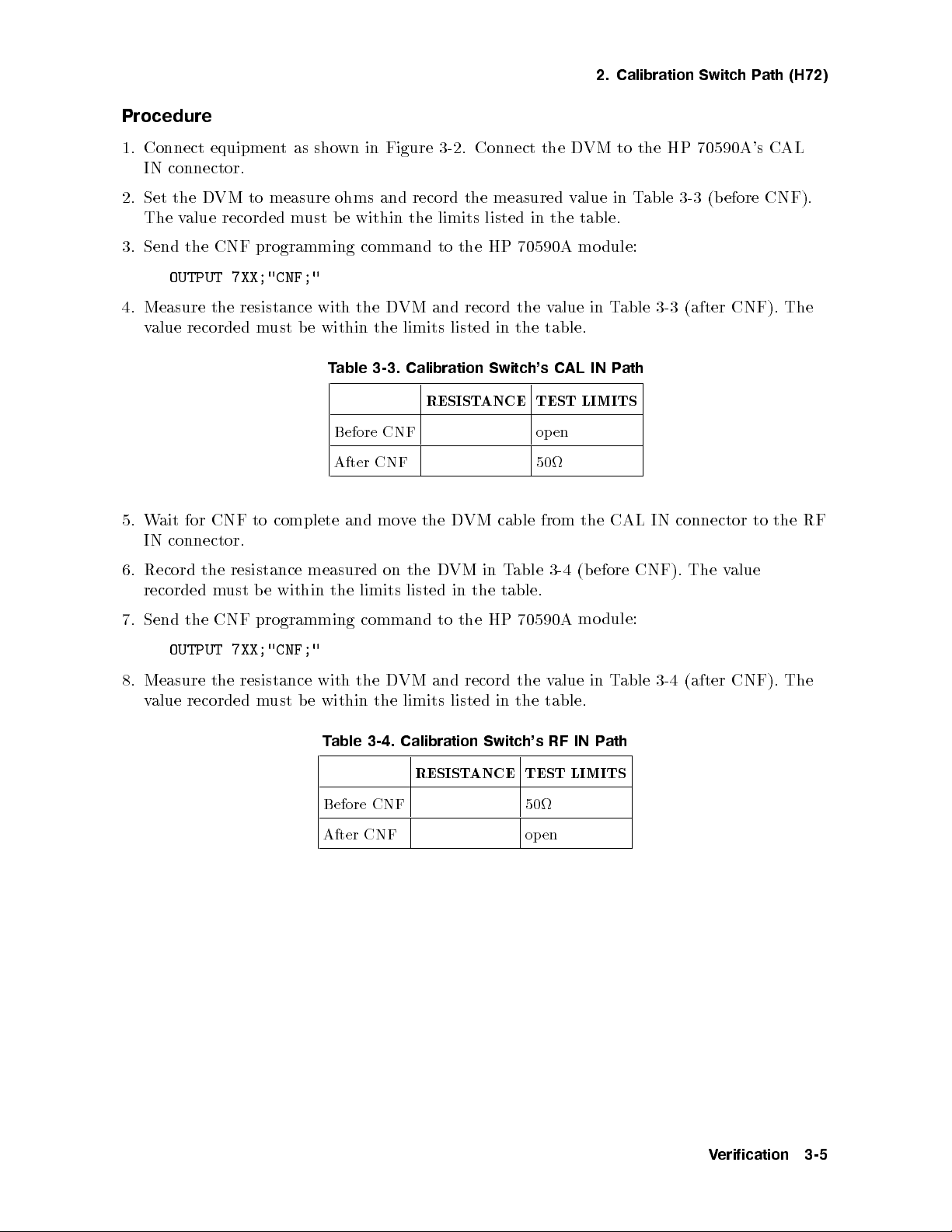
Procedure
1. Connect equipmentasshown in Figure 3-2. Connect the DVM to the HP 70590A's CAL
IN connector.
2. Set the DVM to measure ohms and record the measured value in Table 3-3 (before CNF).
The value recorded must be within the limits listed in the table.
3. Send the CNF programming command to the HP 70590A module:
OUTPUT 7XX;"CNF;"
4. Measure the resistance with the DVM and record the value in Table 3-3 (after CNF). The
value recorded must b e within the limits listed in the table.
Table 3-3. Calibration Switch's CAL IN Path
RESISTANCE TEST LIMITS
Before CNF open
CNF
5.
ait
W
connector.
IN
for
CNF to
After
complete and
mo
VM
D
the
e
v
cable
50
from
the
CAL
connector
IN
to
the
RF
6. Record
recorded
Send
7.
OUTPUT
Measure
8.
value
resistance
the
ust
m
CNF
the
7XX;"CNF;"
resistance
the
recorded m
measured
e
b
within
the
programming
with
within
e
b
ust
able
T
Before CNF 50
After CNF open
the
on
limits
listed
command
VM and
D
the
limits
the
Calibration
3-4.
efore
(b
3-4
able
T
in
VM
D
table.
the
in
dule:
alue
v
table.
RF
mo
IN
in
P
T
ath
the
to
record the
listed
70590A
HP
the
in
Switch's
RESISTANCE TEST LIMITS
CNF).
able
3-4
The
(after
alue
v
CNF).
The
erification
V
3-5
Page 33

3. Discrete Fault Indicator (DFI)
Description
The DFI is normally implemented as a closed relay whose coil is connected across the power
supply of the HP 70590A Option H69 Test Module Adapter. The relay op ens when power is
applied and closes when power is removed from the system. The relay also closes when either
the p ower supply shuts itself down or the HP-MSIB loop is broken.
Equipment
Test Equipment:
Modular Measurement System ........................ HP 71100A/C, HP 71200A/C,
HP 71201A/C, HP 71210A/C,
or HP 71300A/C
Digital Voltmeter .....................................................HP 3456A
50 Termination . . . . . ..................................................HP909D
Adapters:
BNC
(2
re
(f
quir
)to
e
BNC (f
d)
) barrel
..
1250-0080
HP
.
.
.
.
.
.
.
.
.
.
.
.
.
.
.
..
..
..
..
.
.
.
.
.
.
.
.
.
.
.
.
.
.
.
.
.
Cables:
11001-60001
HP
.
.
.
.
.
.
..
..
.
.
.
.
.
.
.
.
.
.
.
.
.
.
.
.
.
.
.
.
.
..
..
.
.
BNC
BNC
(2
r
(m)
(m)
quir
e
to
to
ed)
banana
dual
SMB (f
plug
85680-60093
HP
.
.
.
.
.
.
.
.
.
.
.
.
.
.
.
.
.
.
.
.
.
..
.
.
.
.
.
.
.
.
.
.
.
.
.
.
.
.
.
.
.
.
.
.
)
3-6
erification
V
Figure
3-3.
Discrete
F
ault
Indicator
est Setup
T
Page 34

3. Discrete Fault Indicator (DFI)
Procedure
1. Connect equipmentasshown in Figure 3-3.
2. Set the digital voltmeter to read out in ohm units (resistance).
3. Turn the power on to the modular spectrum analyzer system.
4. Note the resistance on the digital voltmeter and record in Table 3-5.
5. Turn the power o to the modular spectrum analyzer system.
6. Note the resistance on the digital voltmeter and record in Table 3-5.
Table 3-5. Discrete Fault Indicator Readings
Power Setting Resistance
(ohms)
Power ON OPEN
Power OFF 50
Test Limit
erification
V
3-7
Page 35

Page 36

4
Programming
Adding the HP 70590A Option H69 or Option H72 TMA to an HP Mo dular Spectrum
Analyzer allows operation of the spectrum analyzer using either CI IL or its native language
command set. This chapter contains the following information:
Detailed information on the native language commands can be found in the HP 70000
Modular Spectrum Analyzer Programming Manual. The CIIL op eration co des are described
in this manual. They are followed byseveral ATLAS/CIIL examples. Finally, there is a
list of all of the ATLAS nouns and noun mo diers (that are implemented) with their CIIL
equivalent.
The ASA resp onds to the following CI IL operation codes: CLS, CNF, FNC, FTH, GAL, INX,
and
A.
noun-mod
<
>
will
hav
ciated
asso
>
alue
v
<
one
e
IST,
Unless
with
OPN,
otherwise
them.
RST,
SET,
stated,
SRN,
all
SRX,
mc
<
har
and ST
>
Programming
4-1
Page 37

Measurement System
The measurement system will hereafter b e referred to as the ASA (Automatic Spectrum
Analyzer). The ASA contains two separate parsers: one for CI IL and one for the nativemode.
The language selected at power-up will be CI IL.
The ASA op erates as b oth a STIM device (for signal conditioning purp oses) and a SENSOR
device for measurements.
At the end of each measurement, the ASA is left with the sweep enabled to facilitate ASA
integration until RST o ccurs.
Noun Modifiers
The ASA reads into variables all of the NOUN MODIFIERS and marks a ag for each
modier that is encountered (an RST function p erforms an instrument preset and clears all
modier ags). From the collection of ags and the ATLAS NOUN, an inference will be made
to
as
their
NOUN
exactly whic
implications)
CIIL
MODIFIERS
h measuremen
pro
are
trigger
whic
t the
vided
h
user is
illustrate
to
actions.
attempting
what
A
e.
mak
to
measuremen
TLAS
will
ts
examples
done
e
b
(and
and
whic
h
Compatibility
After
y
An
GAL
the
In
only
the
de and
mo
Note
receiving
ending
p
command.
nativ
w
a
setup
mo
e
return to
yto
a
will not
When the PROGRAM MESSAGE method is used to switchbetween
languages, there is no change in the POWER UP language state.
Note
Device
A
A Device Clear do
with
command,
GAL
information
the
de,
generate
Clear,
TR
TN
Nativ
IL
CI
CIIL
a
commands
UE
Operation
e
commands
all
to
onds
will
IL
function
switc
T
resp
the
to
in
from nativ
h
dened
e
b
rigger, Serial
dened
as
as
P
ASA
emo
dumm
a
oll,
b
the
e
b
will
command
mode.
error.
tax
syn
Group
Execute
analyzer
programmed
will
CI
will
es NOT cause the language mode to be c
efore
b
de
and
ythe
in
the
IL
CI
to
command
y
other
language
hanged.
nativ
the
completion
de.
mo
in
device
dep
that
mo
e
This
the
enden
activ
is
de.
of the
is
IL
CI
t
e.
Programming
4-2
Page 38

Calibration
The ASA is calibrated byproviding a suitable signal at the selected input and specifying
:CH16 through :CH19 (for inputs 0-3). This calibrates the insertion loss dierences of the
resolution bandwidth lters, their frequency osets, step gain osets, etc. The calibration will
remain in eect until another calibration is performed. In addition, path loss correction may
be performed by sending the setup string:
FNC CAL POWR :CHnn
SET FREQ <value> SET PRDF <value>
..
SET FREQ <value> SET PRDF <value>
<cr/lf>
Up to 20 points may b e supplied. The PRDF values are correction factors to b e added to the
measurements. This correction will remain eectiveuntil the next RST command. For further
information, refer to the AMPCOR command in the ASA command reference manual.
Note
Measurement
ASA
The
with
and
gather
to
up
commands.
FETCH
will
parameters from
MONITOR
the
The frequency/amplitude pairs MUST be sent in ascending frequency order
(lo
est
w
frequency
rst).
Modes
h
(suc
erbs
tended
in
is
single
data
Therefore,
erform data
p
to
and
the
v
b
same
action
statemen
used
be
(suc
erbs
able
e
INITIA
TE
reduction on
INITIA
function
to
t
to
with
as
h
return
will
TE.
m
oth
b
INITIA
ultiple
m
ys
a
alw
the
in
This
correctly
ultiple
and
TE
measuremen
a
(as
gathered
teraction
.
action
A
FETCH).
minimum)
allo
data
een
w
et
b
TLAS
v
is
ASA
The
through
ts
a
trigger another
return
the
wing
FETCH
and
sp
series
INITIA
MEASURE)
as
ecically
of FETCH
eep
sw
eral
sev
of
TE
and
It is expected that the measurement throughput will be b etter using single action verbs
because it is p ossible to avoid multiple setups to accomplish related measurements.
set
allo
ws
Programming
4-3
Page 39

CLS
Syntax
CLS :CH00
Description
This command closes the sensor connection. When REFO has b een sent as part of the setup,
this command will trigger the programming of the ASA. (The ASA is being used as a signal
conditioner in this case.) Otherwise, this command causes no action. The CLS command will
also put the analyzer in continuous sweep mode. (Again, REFOmust be sent as part of the
setup string.)
Programming
4-4
Page 40

CNF
CNF
Syntax
CNF
Description
The following tests are executed by this command. After execution, the ASA will be left in its
instrument preset state.
Note
Always wait approximately three minutes after p ower-on to execute this
command. If this command is executed too early, not all of the following test
will b e run.
Note
This command assumes a 300 MHz,010 dBm signal is present at the ASA's
input port.
ests
T
TMA
ksums
Chec
OM
R
RAM test
I/O
ests
Sla
ksums
cessor
e
bus c
Addressing
e
v
Integrit
RAM
e
hec
y
k
Order
test
Non-destructiv
ternal
In
System
T
HP-MSIB
OM
Path
Chec
Signal
R
Non-destructiv
Video
Pro
100 MHz Reference
300 MHz Reference
Fractional N Synthesizer
Idler Phase-lo ckLoop
requency
F
une
T
Decade
Binary Span A
Sweep D
Correction D
YTO
Input A
Con
C
A
D
uator
Atten
Span
ttenuator
AC
AC
Limits
ttenuator (uncalibrated)
Board Adjust
trol
Step Gain(s) (uncalibrated)
Resolution Bandwidths (uncalibrated)
frequency
ter
cen
oints,
p
dB
includes:
hing
Switc
Calibration
Amplier(s)
Log
3
(uncalibrated)
uator(s)
tten
A
(uncalibrated)
(uncalibrated)
amplitude
,
Programming
4-5
Page 41

CNF
Display Tests
(if present)
HP-MSIB Interface
Test SwitchPosition
ROM Checksums
Non-destructive RAM Test
8041 Peripheral Processor
Pixel RAM
Bit-slice Pro cessor
Peripheral to Bit-slice Interface
Dot Generator
Character ROM Checksum
Programming
4-6
Page 42

FNC
Syntax
FNC
FNC<noun
Description
This command signies the beginning of an instrument setup string. The noun and mchar are
saved for later use in determining which measurement algorithm is to be initiated. Validation
of the<noun>or<mchar>is performed and an error message is sentifaninvalid item is
found. Except as noted below, all<noun>sand<mchar>s are treated the same. This is done
to facilitate the instrument's use as a signal conditioning mo dule.
Note
and
ILS
transform.
ILS
SWPT
RESB
A
T
><
mchar>:CH00
Setups are cumulative and are only reset by an RST command. The FNC
op-code is followed by an arbitrary number of SET, SRN, and/or SRX
op-codes. The purpose of the FNC op-co de and its collection of SET, SRN,
and SRX op-co des is to indicate which are to aect changes in the module
curren
F
a
conditions
.
.
.
.
.
.
.
.
.
.
Those not
t
ourier
.
.
..
state
included
mo
CAN
Unless
.
.
.
.
.
.
transitioning
in
in the
dule.
measuremen
ecically
sp
.
.
.
.
.
.
.
.
.
.
.
..
.
.
.
.
.
ts
o
..
.
.
.
.
.
.
.
from
FNC setup
imply
verridden
.
.
.
a
.
.
.
.
.
.
.
.
.
.
.
.
time
in
.
.
.
.
the
are to
domain
the
.
.
.
.
.
.
.
.
curren
remain
SET
.
.
.
.
..
.
.
.
t state
as
setup
commands,
..
.
.
.
.
.
.
.
.
.
.
.
.
to the
dened
and the
.
.
.
.
.
.
.
.
.
next state.
the
in
use
default
the
.
.
.
.
.
.
.
.
.
.
.
.
.
.
of
state
.
.
.
.
the
of
are:
ms
.200
.
.
.
kHz
1
.
.
.
.
.
CAN
A
T
.
.
.
.
.
.
.
.
.
.
.
.
.
.
.
.
..
..
.
.
.
.
.
.
.
.
.
.
.
.
.
.
.
.
.
.
.
.
.
..
..
.
.
.
.
.
.
.
.
.
.
.
.
.
.
.
.
.
.
har
.
.
>
CAL
.
.
.
.
.
\NOPD"
of
used
is
..
..
.
.
.
.
.
.
.
.
.
.
.
.
.
.
.
.
.
..
..
..
..
.
.
.
.
.
.
.
.
.
.
.
.
.
.
.
.
.
..
..
..
..
.
.
.
.
de.
FREQ
mo
and
or
transfer
to
\NOAD"
path-loss
will
the
place
correction
ASA
data.
sample
in
Refer to
detection
the
SWPT
RESB
VOR
XSAM . . ....................................................................15
RESB ...................................................................1 kHz
FRQW .................................................................30 kHz
mc
<
An
noun
The
descriptions.
200
.
.
.1
..
PRDF
ms
kHz
Programming
4-7
Page 43

FTH
Syntax
FTH<mchar
>
Description
After the data has been gathered, this command is used to fetchvarious characteristics of
the data. A syntax error is generated if an<mchar>is requested that is not specied in this
section.
If the channel number is greater than 19 when the FTH is executed, it assumes that a
user-dened function (downloaded into the analyzer at test-station initialization) is to be
executed. The function is executed before the<mchar>is evaluated and the channel is then
reset to zero (so that the function will only be executed once).
RESP>1
er
umb
This
data
of
har
mc
<
WR
PO
T
VOL
SMPL
alue
v
indicates
items
argumen
>
returns
returns
returns
to
that
sen
e
b
denitions:
t
RESP
RESP
RESP
to the
t
en
an
items
items
items
data
tire
computer.
trace
from
trace
from
trace
from
set
to
is
Ain
in
A
in
A
transferred.
e
b
dBm.
olts.
v
olts.
v
RESP indicates
the n
rst.
PRDF
are 6
In
dB
and
the
SPEC
returns
and
and
the
SGTH
divisions
9
should
amplitude (in
the
that
t
en
ev
sorted
sp
elo
b
that order)
resp
ectrum
included
e
b
w the
onse
signal
y
(b
in
reference lev
h
eac
for
greater
is
list
the
signal
amplitude)
string
setup
ectiv
resp
el
found
the
than
to
(the
ely).
largest
ber
um
n
a resp
default
Output
signal
of signals
onse
lev
ector.
v
values
frequency
is
el
found, the
remaining elements will be lled with zeroes.
SIGS returns the sorted spectrum (by frequency) to a response vector. PRDF and SGTH
should be included in the setup string (the default values are 6 dB and 9 divisions
below the reference level respectively). Output is frequency and amplitude (in that
onse
resp
elemen
the
ts
will
e
b
order)
is
list
lled
each
for
greater
with zero
signal
than
es.
the
found
um
n
lo
er of
b
est
w
frequency
signals
rst.
found,
In
remaining
the
the
ev
en
t that
RESP1 (or not specified)
alue indicates that a single data item is b eing
This v
<
mchar>argument denitions:
requested.
FREQ executes a p eak search and returns marker frequency.
dBm.
W executes
XPO
T
XVL
executes
returns
and
h
searc
eak
p
a
returns
and
h
searc
eak
p
a
mark
mark
amplitude
er
amplitude
er
in
in
olts.
v
VLPK
Programming
4-8
executes
volts.
returns
and
h
searc
eak
p
a
mark
amplitude
er
in
Page 44
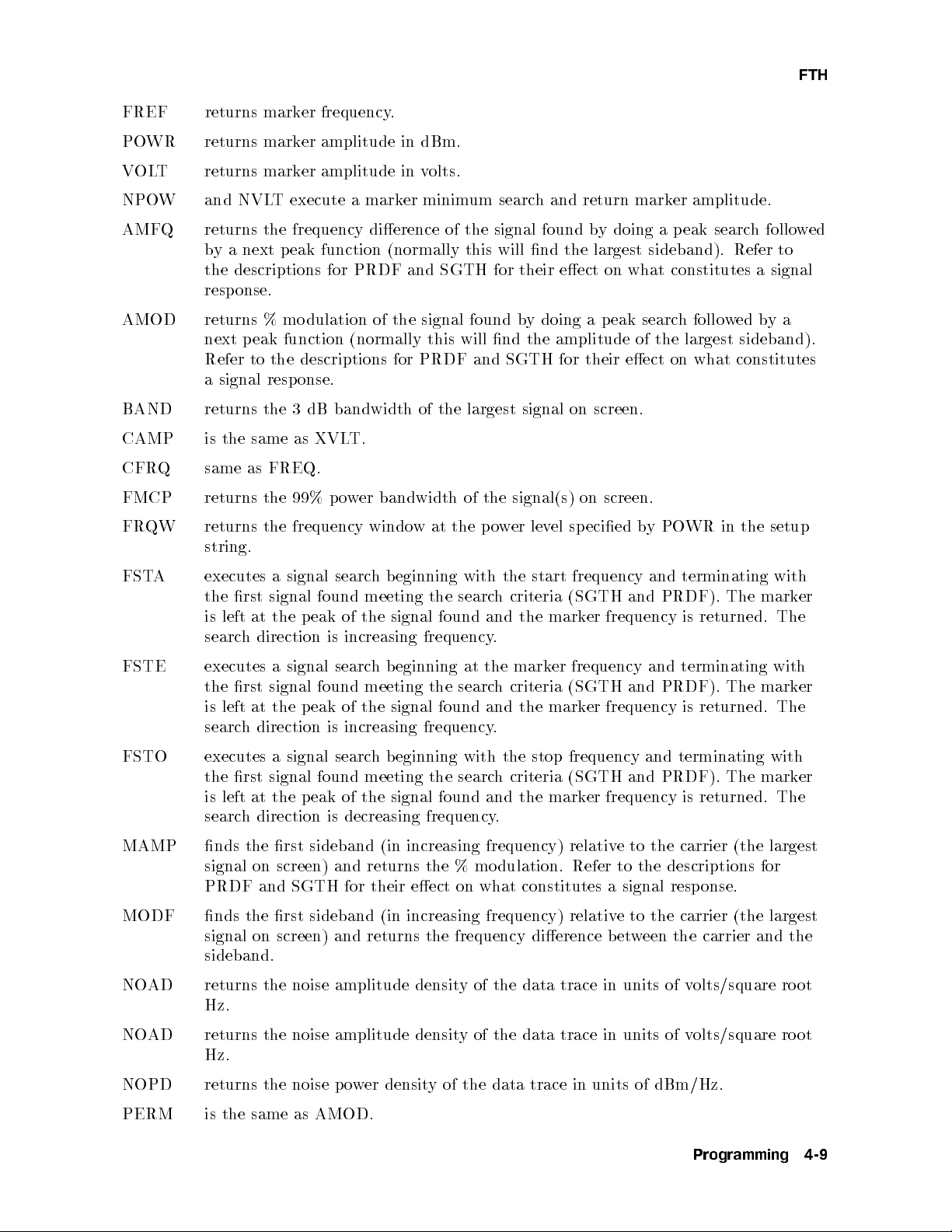
FTH
FREF returns marker frequency.
POWR returns marker amplitude in dBm.
VOLT returns marker amplitude in volts.
NPOW and NVLT execute a marker minimum search and return marker amplitude.
AMFQ returns the frequency dierence of the signal found by doing a peak search followed
by a next peak function (normally this will nd the largest sideband). Refer to
the descriptions for PRDF and SGTH for their eect on what constitutes a signal
response.
AMOD returns % mo dulation of the signal found by doing a peak search follo wed bya
next p eak function (normally this will nd the amplitude of the largest sideband).
Refer to the descriptions for PRDF and SGTH for their eect on what constitutes
a signal resp onse.
BAND returns the 3 dB bandwidth of the largest signal on screen.
CAMP is the same as XVLT.
FREQ.
returns
as
the
99%
screen.
bandwidth
er
w
o
p
of
signal(s)
the
on
Q same
CFR
FMCP
setup
FR
QW
returns
frequency
the
windo
ecied
sp
el
lev
er
w
o
p
the
at
w
b
WR in
yPO
the
string.
A
FST
FSTE
executes
rst
the
at
left
is
h
searc
executes
rst
the
at
left
is
h
searc
signal
a
signal
p
the
direction
signal searc
a
signal
p
the
direction
searc
found
eak
is
found
eak
is
eginning
hb
meeting
signal
the
of
increasing
eginning
hb
meeting
signal
the
of
increasing
with
searc
the
found
frequency
the
at
searc
the
found
frequency.
the
h
and
.
h
and
start
criteria
mark
the
mark
criteria
mark
the
frequency
(SGTH
er
frequency
er
(SGTH
er
and
PRDF).
and
frequency
terminating
and
PRDF).
and
frequency is
terminating
The
returned.
is
The
returned. The
with
mark
The
with
mark
FSTO executes a signal search beginning with the stop frequency and terminating with
the rst signal found meeting the search criteria (SGTH and PRDF). The marker
is left at the peak of the signal found and the marker frequency is returned. The
search direction is decreasing frequency.
largest
MAMP
the
nds
signal
on
PRDF and
sideband
rst
screen)
SGTH
and
for
increasing frequency)
(in
%
returns
their
the
eect
on
dulation.
mo
what
constitutes
relativ
Refer
MODF nds the rst sideband (in increasing frequency) relativ
signal on screen) and returns the frequency dierence b et
carrier
the
to
e
the descriptions
to
signal
a
resp
e to the carrier (the largest
ween the carrier and the
(the
for
onse.
sideband.
er
er
NOAD returns the noise amplitude densit
Hz.
NO
AD
returns
the noise
amplitude
densit
Hz.
of
y
densit
er
w
o
p
noise
the
the
same
AMOD.
as
NOPD
PERM
returns
is
y of the data trace in units of v
of
units
in
trace
data
the
of
y
the
data
trace
units of
in
dBm/Hz.
olts/square ro ot
olts/square
v
ro
Programming
ot
4-9
Page 45

FTH
PERI returns the p eriod of a signal (inverse of FREQ).
PRDF returns the value of the user dened variable UnTMP whichmay be loaded bya
user dened function specied by :CHnn.
PREF executes a probability density function in amplitude and returns the amplitude
having the greatest number of signal responses. This is a convenientwayof
determining where the noise oor is.
RMSV returns the RMS value of 800 data points of the data trace.
SBCF returns frequency for VOR subcarrier (9960 Hz).
SBCM returns % mo dulation of VOR subcarrier (30%).
Time Domain Setup
The following measurements imply a time domain setup (refer to FNC).
AMMC returns the % mo dulation of the 15 Hz tacan signal.
AMMF returns the % modulation of the 135 Hz tacan signal.
AMSH
DDMD
DMDS
HMDF
LMDF
MMOD
AM
returns
returns
returns
returns
the
dierence
the
frequency
measured
returns measured
mo
returns
mean
of
shift
in
dominan
of
frequency
frequency
dulation
tacan
a
depth
of
signal.
mo
of
dulating signal
tmo
Hz
150
of
Hz
90
of
signal.
ILS
dulation
signal.
ILS
signal.
ILS
of
ILS
(ILS).
signals.
4-10
Programming
Page 46

GAL
GAL
Syntax
GAL
Description
GAL (Go to Alternate Language) is available only in CIIL; it is not available in ATLAS.
Points all succeeding commands to the native code parser. This condition will remain in eect
until the CIIL command is encountered.
Programming
4-11
Page 47

INX
Syntax
INX<mchar
>
Description
This command initiates the programming of the ASA to acquire the signal(s) of interest.
INX as a minimum always triggers a sweep (in the case of multiple INX FTH sequences).
This command formats an output of the anticipated measurement time in seconds. The
noun-modiers RESP and FREF do not require an INX to eect a change in the ASA.
The next FTH will takeinto account their currentvalue. This is done to facilitate data
interrogation.
An INX command will force the analyzer into the single sweep mode of operation. When in
the XSAM mo de of data collection (multiple sweeps in max-hold), successive INX commands
will trigger one more sweep unless an FNC, SET, SRN, or SRX command has been received.
to
Refer
When
INX
has
in
commands
een
b
details. V
>
har
mc
<
description
the
SAMA
the
receiv
alidation
receiv
is
ed
will
which
ed.
mo
a
of
for
de
erage
v
inv
<
the
Except
XSAM
data
of
one
alidates
har
mc
as
for
collection
sw
more
the
p
is
>
noted
conditions
the
(m
of
eep
collected
erformed
elsewhere,
ultiple
data
data.
and
all
h
whic
eeps
sw
unless a
Refer
error
an
har
mc
<
the
clear
eraged
v
a
SET, SRN,
description
the
to
message
are
s
>
accum
ulated
together),
SRX
or
issued
is
treated the
data.
successive
command
SAMA
for
in
an
if
b
same
v
y
for
alid
this
command.
4-12
Programming
Page 48

IST
IST
Syntax
IST
Description
IST (InstrumentSelf Test) is available only in CI IL; it is not available in ATLAS). After
execution, the ASA will be left in its instrument preset state. The following tests are executed
by this command.
Note
Always wait approximately three minutes after p ower-on to execute this
command. If this command is executed to early, not all of the following test
will b e run.
Note
ests
T
TMA
Checksums
OM
R
Non-destructiv
ternal
In
System
HP-MSIB
Checksums
OM
P
Signal
R
Non-destructiv
This command assumes a 300 MHz,010 dBm signal is present at the ASA's
ort.
p
input
est
T
RAM
e
k
Chec
Bus
I/O
ests
T
Addressing
e
v
Sla
y
tegrit
In
ath
est
e RAM
T
Video Pro cessor
100 MHz Reference
300 MHz Reference
Fractional N Synthesizer
op
Lo
k
C
AC
c
trol
ttenuator
DAC
Board
ttenuator
Phase-lo
Idler
requency Con
F
A
D
une
T
Decade Span A
Binary Span A
Sweep D
Correction
YTO Limits
Input Attenuator (uncalibrated)
Step Gain(s) (uncalibrated)
Resolution
includes:
hing
Switc
Calibration
Bandwidths
p
dB
3
(uncalibrated)
uator(s)
tten
A
(uncalibrated)
cen
ts,
oin
Order
Adjust
frequency
ter
(uncalibrated)
amplitude
,
Programming
4-13
Page 49

IST
Log Amplier(s) (uncalibrated)
Display Tests
(if present)
HP-MSIB Interface
Test SwitchPosition
ROM Checksums
Non-destructive RAM Test
8041 Peripheral Processor
Pixel RAM
Bit-slice Pro cessor
Peripheral to Bit-slice Interface
Dot Generator
Character ROM Checksum
4-14
Programming
Page 50

OPN
OPN
Syntax
OPN :CH00
Description
The ASA do es not have the ability to isolate itself from the rest of the test station. However,
to facilitate ASA integration, this command will set the analyzer to continuous sweep mode.
Programming
4-15
Page 51

RST
Syntax
RST<noun
Description
The ASA returns to its instrument preset condition upon receiving this command and clears
its service request mask. This command sets the initial conditions for all FNC commands to
follow. The marker will be set to center screen. Validation of the<noun>or<mchar>is
performed and an error message is issued if an invalid item is encountered. All<noun>sand
<
mchar>s are treated the same. This is done to facilitate the instrument's use as a signal
conditioning mo dule.
><
mchar>:CH00
4-16
Programming
Page 52

SET, SRN, and SRX
Syntax
SET, SRN, and SRX
SET<noun-modier
<
value
>
><
value>SRN<noun-modier
><
value>SRX<noun-modier
>
Description
These three commands specify the setup conditions of the ASA for making a measurement.
SRN and SRX set minimum and maximum values respectively while SET sp ecies a nominal
value.
SRN exp ects to set the algebraically lesser value and SRX expects to set the algebraically
larger value. Incorrect operation will result if the SRN value is greater than the SRX value.
SRN and SRX are relevant to the<noun-modier>POWR, VOLT, and FREQ or FRQW;
when used with other<noun-modier>s they are the equivalent to the SET command. The
following equivalences are in eect:
W
XPO
SET
to
alen
alen
alent
alen
alen
alen
deriv
(for
dier
ecic
v
<
t
t
t
t
t
t
t
ed
of
alue
SET
to
SET
to
SET
to
SET
to
SET
to
SET
to
SET
to
from the
oltage
v
TTN,
A
s
>
alues.
v
umeric
n
a
All
.
>
W
NPO
T
XVL
T
NVL
FSTO
A
FST
FSTO
A
FST
bination
com
readouts).
FSTE,
All
RESB,
The automatic
.
>
alue
v
<
noun-mo
<
dier
NPO
of
measuremen
SWPT,
selection mo
automatic
The
ecting
exp
s
>
and
W
ts
SMPW,
XPO
b
will
enabled b
de is
selection
umeric v
n
(for
W
made
e
VBAN
mo
alues will
dBm
in
can
y
de
readouts)
log
be
sending
disabled
is
set
the
default
SRX PO
SRN
SRX
SRN
SRX
SRN
SRX
SRN
Amplitude
and NVL
de.
mo
WR is
WR
PO
OL
V
OL
V
QW
FR
QW
FR
FREQ
FREQ
T
The
scaling
and
<
automatically
<
b
v
y
alue
>
sending
AUTO
a
equivalen
equiv
is
equiv
is
T
is equiv
T
equiv
is
equiv
is
equiv
is
equivalen
is
XVL
noun-mo
to
or
in place
umeric
n
is
T
sp
to zero if the value eld is not present. Specifying a<noun-modier>not contained in this
document will result in a syntax error.
Noun-modifiers
alue
TTN
A
sets
A
>
alue
<
v
reference lev
UTO
el will be less
atten
RF
the
CAMP is the same as V
uator to
main
will
OLT.
ecied
sp
the
the
tain
than or equal to
v
RF-atten
CFRQ is the same as FREQ.
XPOW is used to set the reference level of the ASA.
XVLT is used to set the reference level of the ASA.
PO
FST
WR
A
mark
the
sets
measuremen
sp
ecies
start
amplitude
er
a
at
ts
frequency
sp
ecic
.
at
ecied
sp
the
lev
er
w
o
p
PO
el.
(0|70
uator
0
10 dBm at the input mixer.
WR
dB
setting suc
making
when
h
that
FR
steps).
dB
10
in
Programming
signal
a
QW
The
at
the
4-17
Page 53

SET, SRN, and SRX
FSTO species stop frequency.
FREQ species center frequency.
Note
FREQ sp ecies the frequency for an amplitude correction value (whichwould
be used to correct for test ASA path loss) for the CAL noun.
FRQW species frequency span.
FSTE sets center frequency step size (for step keys) and steps the center frequency up one
step. The<value>AUTO sets the step size to one tenth the span.
FREF sets the marker frequency.
FRES sets the nal span for an autozo om operation.
MAXT sets maximum delayuntil trigger.
PRDF sets the signal peak recognition criterion used in SPEC. This is the p ower
dierence that a response must exhibit in order to be classied as a signal. The
Q,
AMF
ts:
AMMF,
added
e
b
CAL
AMSH,
to
noun.
the
Note
PREF
default
AMOD,
DDMD,
PRDF
measuremen
the
sets
alue
v
FSTA,
DMDS,
sp
displa
This parameter
6dB.
is
FSTE, FSTO,
HMDF,
ecies the
result
t
line.
y
aects the
MODF,
MAMP
LMDF,
,
MMOD,
SBCF,
amplitude correction
ASA
test
to
correct
for
follo
PERM,
alue
v
path
wing
SBCM.
(whic
loss)
measurmen
AMMC,
to
is
h
the
for
exceed
ust
SGTH
nine
signal
b
divisions
sets the
threshold
is
measuremen
AMMC,
AMMF,
threshold
PRDF
y
ts:
elo
b
AMF
AMSH,
used
to
order
in
reference
the
w
Q, AMOD,
DDMD,
SPEC
for
classied
e
b
el.
lev
FSTA,
DMDS, HMDF,
measuremen
as
This
ts.
signal
a
parameter
FSTE, FSTO,
LMDF, MMOD,
signal
A
resp
MAMP,
m
The
onse.
aects the
MODF,
default
following
PERM,
SBCF, SBCM.
REFO enables the signal conditioning mode of operation. It is assumed that the video
output will b e digitized by a high sp eed ADC. This is required in order to use the
ASA as a signal conditioning (or stimulus) device. This mnemonic causes the ASA
to be setup when the CLS command is received.
sets
UTO
A
>
alue
v
<
span.
The
t data.
the sw
eep time as a
provided
RESB
sets
resolution
the
resolution
RESP species the
SWPT sets the sw
function of frequency span, resolution
SMPW sets the sw
frequency
of
sequence).
bandwidth
bandwidth
as
function
a
lter (1/3
number of items to b e returned as measuremen
<
eep time of the ASA. The
value>AUTO sets
bandwidth, and video bandwidth.
eep time of the ASA (zero span w
aveforms). This mnemonic is
as a convenience to the ATLAS user. Its function is identical to SWPT including
the<value>AUTO.
trigger.
video
for
el
V
TRL
TRSC
sets the
trigger
sets
trigger
lev
source:
INT
EXT
LINE
VID.
this
alue
v
the
4-18
Programming
Page 54

SET, SRN, and SRX
VBAN sets the video bandwidth of the ASA (1, 3, 10 sequence). The<value>AUTO sets
the video bandwidth as a function of resolution bandwidth.
SAMN selects negative-p eak detector and can specify the number of sweeps to be taken.
Value eld is optional.
SAMP selects positive-peak detector and can specify the number of sweeps to be taken.
Value eld is optional.
SMPL selects the sample detector and can specify the number of sweeps to be taken.
Value eld is optional.
SMPP selects the detector to the normal (negative peak and positiv e peak) mo de
of operation and can sp ecify the number of sweeps to b e taken. Value eld is
optional.
SAMA selects the sample detector and species the number of sweeps to be averaged
together. This mo de is reset by selecting any of SAMN, SAMP, SMPL, or SMPP
with a<value>
1(or<value>not sp ecied). The accumulated data will b e
cleared if a state change in the ASA invalidates the measurement data. This
occurs when any of the following are SET: NPOW, XPOW, NVLT, XVLT, FSTA,
QW,
FR
RESB,
FSTO,
FSTE,
SMPL, SAMA,
FREQ,
FRES,
SWPT, VBAN,
TTN,
A
NOAD,
SMPP,
NOPD.
XSAM, SAMN,
SAMP,
alue eld
V
en.
tak
e
b
to
eeps
sw
of
er
b
um
n
the
ecify
sp
can
This
alue
v
a state
an
FSTO,
used
>
and
mo
>
c
of
y
FSTE,
SAMA,
op
om
in
is
de
(or
1
hange
the
erations
the
b
reset
alue
<
v
the
in
wing
follo
FREQ,
SWPT,
sp
setup
selecting
y
not
>
ASA
are
FRES,
VBAN,
ecifying
string
sp
in
SET:
can
v
A
of
y
an
ecied).
alidates
NPO
TTN,
AD, NOPD.
NO
FRES.
terrogated
in
e
b
SAMN,
The
the
W,
SMPP
SAMP
accum
ulated
measuremen
NVL
W,
XPO
XSAM,
,
mo
This
sending
y
b
, SMPL,
data
data.
t
XVL
T,
SAMN,
is
de
the
SAMP
susp
max-hold
SAM
sets
optional.
<
a
with
cleared
ccurs
o
FR
RESB,
during
Defined
User
noun-mo
<
y
An
<
noun-modier>followed by a question mark (?). If the channel number is greater than
if
when
QW,
SMPL,
autozo
Function
dier
is
or SMPP
e
b
will
This
FST
T,
,
ended
A,
19 when the setup is activated (CLS and REFO or INX), it is assumed that a user-dened
function (downloaded into the analyzer at test station initialization) is to be executed. The
function is the last item in the setup to be done and the channel will then be reset to zero (so
the function
that
unction
F
naming
will
conv
only
tion:
en
executed
e
b
once).
CH20: USERA
CH21: USERB
.
.
.
CH45: USERZ
CH46: USERAA
.
.
.
CH71:
USERAZ
Programming
4-19
Page 55

SET, SRN, and SRX
CH72: USERBA
.
.
.
CH97: USERBZ
CH98: USERCA
CH99: USERCB
Channels 0|3 specify the input port to be used (if multiple ports are available).
Channels 4|7 select input ports 0|3 and enable currently stored pathloss data to
be applied to the measurments. Once enabled, this correction will
continue until the next RST is received.
Channels 8|11 select input p orts 0|3 and perform a preselector peak function as part
of the measurement (if a tunable preselector is available on the input
selected).
Channels 12|15 select input ports 0|3, enable currently stored pathloss data, and
perform the preselector p eak function.
cedure
Channels 16|19
select input
appro
es
(tak
ust
signal
m
0|3
ports
ximately
presen
e
b
and
2|3
at
t
p
min
the
erform
utes).
selected
the
The
input.
in
ternal
calibration
appropriate
pro
calibration
4-20
Programming
Page 56

STA
Syntax
STA
Description
STA
Requests the current operation status. Normal return is<sp
Error Messages
F05ASA (MOD) Measurement Timeout
F07ASA (MOD) CI IL/HPIB Syntax Error
F07ASA (MOD) HARDWARE Error
F07ASA (MOD) INVALID RESPONSE LENGTH
F07ASA (MOD) INVALID MEASUREMENT
CHARACTERISTIC
F07ASA
CHARA
F07ASA
app
de
ASA
hex
Bit 0
is
Message
Error
The
bits.
are
co
of
Manual.
The bits
(MOD) UNRECOGNIZED
CTERISTIC
(MOD)
CNF/IST
Digits
the
digits
is
ended
ended
app
error
In
for w
all
(H)
the
as
des,
co
cases
ord 1
represen
least
decimal
the
to
refer to
a
are
t
signican
um
n
of
end
the HP
means
zero
follo
as
Error:
results
t
ers
b
the
ws:
MEASUREMENT
HHHH
of tests
error
The
bit.)
displa
a
If
(N).
message
as
70900A
passed.
test
.
.
,N
f
run
co
y
a decimal
cal
Lo
gf
,N
.
the
y
b
rep
des
presen
is
um
n
Oscillator
,M
orted
><
crlf>.
g
on
TMA
y
b
rep
and
t
(M).
er
b
Installation
the
ASA
the
orts an
or
F
TMA.
tests
error,
further
and
w
(A
(5
its
information
erication
V
ord
ossible)
p
error
16
is
bit 0: ROM (msb) checksum error
bit 1: ROM (lsb) checksum error
bit 2: RAM (msb) checksum error
bit 3: RAM (lsb) checksum error
bit 4: MSIB I/O fail
5:
bit
6:
bit
bit 15:
Timer
Conguration
fail
Processor fail
error|no
LO
mo
dule
found
Programming
4-21
Page 57

Programming Examples
The Atlas/CIIL examples included in this section are illustrative only; they are not inclusive.
Syntax:
fg
select one of list
[] encloses optional items
j
separates alternative selections
4-22
Programming
Page 58

Trace Transfers Using CIIL
Trace Transfers Using CIIL
There are two metho ds of acquiring trace data (multiple resp onses) using CI IL commands:
1. Raw trace transfers
2. Ordered signal pairs transfers
Raw Trace Transfers
The initiate (INX) portion of the setup results in a signal spectrum (trace) of amplitude
versus frequency. The trace is transferred starting with the lowest frequency. The number of
points transferred is dened by:
SET RESP <number>
In HP 70000 systems the practical limit on the trace length is 800 points. In HP 8566B
systems this limit is 1001 points.
The
raw
Note
method results in the transfer of that portion of the trace sp ecied
by the RESP parameter. If SET RESP 10 is used in a setup, then the rst 10
returned.
e
b
will
trace
the
of
ts
oin
p
The
PO
VOL
SMPL
The
FNC
SET FREQ
SET
SET
CLS :CH0
noun-mo
alid
v
returns
WR
returns
T
returns items
wing
follo
ACS
FRQW
RESP
diers
items
items
is an
:CH0
POWR
1E9
2E9
800
<cr><lf>
for
in
v
in
v
in
example
r
ultiple-p
m
dBm units.
units.
olt
units.
olt
setup
IL
CI
onse
esp
t
oin
string
(RESP
for
>
ra
1) ra
trace
w
wtrace
transfers:
transfers
are:
INX POWR <cr><lf>
FTH POWR <cr><lf>
response=800 data items
Ordered Signal Pairs Transfers
pro
e
b
y
ap
ma
o
w
dierence
er
ectrum
sp
A
meeting
The noun-mo dier SIGS
cessed to
yield
signal
only
criteria.
returns signal data as frequency/amplitude pairs sorted b
resp
y frequency
ecied threshold
sp
a
e
v
o
ab
onses
(low to high). The noun-mo dier SPEC returns signal data as frequency/amplitude pairs
sorted b
y amplitude (highest
response rst).
and
The following is an example CIIL setup string for
FNC ACS SPEC :CH0
dB
6
e
b
SET
SET
PRDF
SGTH
6
0
70.0
a
a
signal
signal
must
must
have
a
sorted signal transfers:
adjacent
higher
minimum
than
r
esp
onse
of
ctrum
e
sp
dBm.
70
0
Programming
4-23
Page 59

Trace Transfers Using CIIL
SET FREQ 1E9
SET FRQW 2E9
SET RESP 20
CLS :CH0 <cr><lf>
INX SPEC <cr><lf>
FTH SPEC <cr><lf>
Note
response
response=20 data items,10 signals
PRDF and SGTH are critical parameters for this setup. If fewer than RESP/2
signals meeting the PRDF and SGTH criteria are found, then the response
will b e padded with 0,0 pairs.
4-24
Programming
Page 60

Measuring Power
ATLAS Example
ATLAS: MEASURE, (POWER), <noun>,
{ VOLTAGE RANGE <value> V TO <value> V |
VOLTAGE MIN <value> V, VOLTAGE MAX <value> V |
VOLTAGE MAX <value> V |
VOLTAGE <value> V |
POWER RANGE <value> DBM TO <value> DBM |
POWER MIN <value> DBM, POWER MAX <value> DBM |
POWER MAX <value> DBM |
POWER <value> DBM
}
, FREQ-WINDOW RANGE <value> HZ TO <value> HZ
[, FREQ-RESOLUTION <value> HZ ]
ATTEN
[,
RESOLUTION-BANDWIDTH
[,
<value>
[, VIDEO-BANDWIDTH
MAX-SAMPLE
{
[,{
SAMPLE-AVG
|
<value>
[
TRIG-SOURCE
[,
connection
<
]
{
field
[,
]
DB
<value> HZ
POS-SAMPLE
|
|INT
EXT
$
>
SWEEP-TIME
<value>
]
|
<value>}]
]
}
<value>
HZ ]
NEG-SAMPLE
SEC]
SAMPLE
|
SAMPLE-PP}
|
Measuring Power
Example
CIIL
:CH00
CIIL:
SRN
{
SET
SET
SET
FNC
VOLT
NVLT
XVLT
VOLT
<noun>
<value>
<value>
<value>
<value>
POWR
SRX VOLT
XVLT
SET
|
|
SRN POWR <value> SRX POWR <value> |
SET NPOW <value> SET XPOW <value> |
SET XPOW <value> |
SET POWR <value> }
FRQW
SRN
[ SET
SET
[
FRQW
FRES
ATTN
<value>
<value>
<value>
SRX
]
]
[ SET SWPT <value> ]
[ SET RESB <value> ]
[ SET VBAN <value> ]
[ SET { { XSAM | SAMP
| SAMN | SMPL | SMPP } [ <value> ] |
SAMA <value> } ]
[ SET TRSC { EXT | INT } ]
CLS :CH00 <cr/lf>
INX
POWR
<cr/lf>
<value> |
<value>
<value>
|
Programming
4-25
Page 61

Measuring Power
ATLAS Response
{ <value> | <error message text> } <cr/lf>
FTH POWR <cr/lf>
CIIL Response
{ <value> | <error message text> } <cr/lf>
[ OPN :CH00 <cr/lf> ]
RST <noun> POWR :CH00 <cr/lf>
4-26
Programming
Page 62

Measuring Voltage
ATLAS Example
ATLAS: MEASURE, ( { VOLTAGE | CAR-AMPL } ), <noun>,
{ { VOLTAGE | CAR-AMPL } RANGE <value> V TO <value> V |
{ VOLTAGE | CAR-AMPL } MIN <value> V,
{ VOLTAGE | CAR-AMPL } MAX <value> V |
{ VOLTAGE | CAR-AMPL } <value> V |
POWER RANGE <value> DBM TO <value> DBM |
POWER MIN <value> DBM, POWER MAX <value> DBM |
POWER MAX <value> DBM |
POWER <value> DBM
}
, FREQ-WINDOW RANGE <value> HZ TO <value> HZ
[, FREQ-RESOLUTION <value> HZ ]
ATTEN
[,
RESOLUTION-BANDWIDTH
[,
<value> HZ
{
[,
<value>
]
MAX-SAMPLE
{
[,
]
DB
POS-SAMPLE
|
SWEEP-TIME
<value>
|
<value>
[, VIDEO-BANDWIDTH
HZ ]
NEG-SAMPLE
SEC]
SAMPLE
|
}
]
<value>
[
TRIG-SOURCE
[,
connection
<
SAMPLE-AVG <value>
|
]
|
EXT
{
$
field
>
INT
}
}
]
SAMPLE-PP
|
Measuring Voltage
Example
CIIL
SRX
:CH00
VOLT
{
|
|
CAMP
<value>
}
CIIL:
SRN
{
SET
SET
FNC
{
NVLT
XVLT
<noun>
VOLT
<value>
<value>
|
CAMP
VOLT |
{
}
SET
|
CAMP }
<value>
<value>
XVLT
SET { VOLT | CAMP } <value> |
SRN POWR <value> SRX POWR <value> |
SET NPOW <value> SET XPOW <value> |
SET XPOW <value> |
<value>
POWR
SET
}
SRN
FRQW
<value>
SRX
<value>
FRQW
[ SET FRES <value> ]
[ SET ATTN <value> ]
[ SET SWPT <value> ]
[ SET RESB <value> ]
[ SET VBAN <value> ]
[ SET { { XSAM | SAMP | SAMN | SMPL | SMPP } [ <value> ] |
SAMA <value> } |
]
}
INT
|
EXT
{
TRSC
SET
[
CLS
INX
:CH00
{
<cr/lf>
VOLT |
CAMP
}
<cr/lf>
|
Programming
4-27
Page 63

Measuring Voltage
ATLAS Response
{ <value> |<error message text> } <cr/lf>
FTH { VOLT | CAMP } <cr/lf>
CIIL Response
{ <value> |<error message text> } <cr/lf>
[ OPN :CH00 <cr/lf> ]
RST <noun> { VOLT | CAMP } :CH00 <cr/lf>
4-28
Programming
Page 64

Measuring Frequency
ATLAS Example
ATLAS: MEASURE, ( { FREQ | CAR-FREQ } ), <noun>,
{ {FREQ | CAR-FREQ} <value> HZ, FREQ-WINDOW RANGE <value> HZ
TO <value> HZ |
{FREQ | CAR-FREQ} MIN <value> HZ,
{FREQ | CAR-FREQ} MAX <value> HZ |
{FREQ | CAR-FREQ} RANGE <value> HZ TO <value> HZ }
{ VOLTAGE RANGE <value> V TO <value> V |
VOLTAGE MIN <value> V, VOLTAGE MAX <value> V |
VOLTAGE MAX <value> V |
VOLTAGE <value> V |
POWER RANGE <value> DBM TO <value> DBM |
|
<value>
POWER
POWER
MIN
MAX
<value>
POWER <value>
DBM
DBM,
DBM |
POWER
MAX
<value>
DBM
}
]
FREQ-RESOLUTION
[,
ATTEN
[,
RESOLUTION-BANDWIDTH
[,
<value>
{
[,
|
<value>
[
TRIG-SOURCE
[,
connection
<
<value>
]
HZ
MAX-SAMPLE
{
SAMPLE-PP }
SAMPLE-AVG
|
]
field
{
<value>
][,
DB
POS-SAMPLE
|
|
EXT
$
>
HZ
SWEEP-TIME
<value>
<value>
]
}
INT
<value>
[,
]
HZ
NEG-SAMPLE
|
]
}
SEC]
VIDEO-BANDWIDTH
| SAMPLE
Measuring Frequency
CIIL Example
CIIL: FNC <noun> { FREQ | CFRQ } :CH00
{ SET { FREQ | CFRQ } <value>
SRN FRQW <value> SRX FRQW <value>
SRN
{
FREQ
|
CFRQ
<value>
}
SRX {
}
{
SRN VOLT <value> SRX VOLT <value> |
SET NVLT <value> SET XVLT <value> |
SET XVLT <value> |
SET VOLT <value> |
SRN POWR <value> SRX POWR <value> |
SET NPOW <value> SET XPOW <value> |
SET XPOW <value> |
<value>
POWR
SET
}
FRES <value>
SET
[
<value>
ATTN
SET
[
]
]
FREQ
|
CFRQ
<value>
}
Programming
4-29
Page 65

Measuring Frequency
[ SET SWPT <value> ]
[ SET RESB <value> ]
[ SET VBAN <value> ]
[ SET { { XSAM | SAMP | SAMN | SMPL | SMPP } [ <value> ] |
SAMA <value> } ]
[ SET TRSC { EXT | INT } ]
CLS :CH00 <cr/lf>
INX { FREQ | CFRQ } <cr/lf>
ATLAS Response
{ <value> |<error message text> } <cr/lf>
FTH { FREQ | CFRQ } <cr/lf>
CIIL Response
{ <value> |<error message text> } <cr/lf>
[ OPN :CH00 <cr/lf> ]
RST
<noun> {
FREQ |
CFRQ }
:CH00 <cr/lf>
4-30
Programming
Page 66

Measuring Bandwidth
ATLAS Example
ATLAS: MEASURE, (BANDWIDTH), <noun>,
{
BANDWIDTH <value> HZ |
BANDWIDTH MIN <value> HZ, BANDWIDTH MAX <value> HZ |
BANDWIDTH RANGE <value> HZ TO <value> HZ
},
{
VOLTAGE RANGE <value> V TO <value> V |
VOLTAGE MIN <value> V, VOLTAGE MAX <value> V |
VOLTAGE MAX <value> V |
VOLTAGE <value> V |
POWER RANGE <value> DBM TO <value> DBM |
<value>
POWER
POWER
MIN
MAX
<value>
POWER <value>
DBM
DBM,
DBM |
POWER
MAX
<value>
DBM
}
FREQ-WINDOW
,
FREQ-RESOLUTION
[,
ATTEN
[,
RESOLUTION-BANDWIDTH
[,
MAX-SAMPLE
{{
HZ
<value>
[,
RANGE
<value>
]
<value>
<value>
[,
]
DB
POS-SAMPLE
|
TO
HZ
]
HZ
SWEEP-TIME
<value>
|
<value>
<value>
]
HZ
NEG-SAMPLE
HZ
VIDEO-BANDWIDTH
[,
}
]
<value>
[
TRIG-SOURCE
[,
connection
<
SAMPLE-AVG
|
]
field
<value>
INT }
|
EXT
{
$
>
}
]
|
SEC]
SAMPLE
|
Measuring Bandwidth
SAMPLE-PP
|
CIIL Example
CIIL: FNC <noun> BAND :CH00
[ { SET BAND <value> |
SRN
{ SRN
SET
BAND
VOLT
NVLT
<value>
<value>
<value>
SRX
SET
SRX
VOLT
XVLT
<value>
BAND
SET XVLT <value> |
SET VOLT <value> |
SRN POWR <value> SRX POWR <value> |
SET NPOW <value> SET XPOW <value> |
SET XPOW <value> |
SET POWR <value>
}
FRQW
SRN
[
[
[
FRQW
FRES
SET
ATTN <value>
SET
SWPT
SET
<value>
<value>
<value>
SRX
]
]
]
<value>
<value>
<value>
]
}
|
|
Programming
4-31
Page 67

Measuring Bandwidth
[ SET RESB <value> ]
[ SET VBAN <value> ]
[ SET { { XSAM | SAMP | SAMN | SMPL | SMPP } [ <value> ] |
SAMA <value> } ]
[ SET TRSC { EXT | INT } ]
CLS :CH00 <cr/lf>
INX BAND <cr/lf>
ATLAS Response
{ <value> |<error message text> } <cr/lf>
FTH BAND <cr/lf>
CIIL Response
{ <value> |<error message text> } <cr/lf>
[ OPN :CH00 <cr/lf> ]
<noun> BAND
RST
:CH00 <cr/lf>
4-32
Programming
Page 68

Measuring Spectrum
ATLAS Example
ATLAS: MEASURE, (SPECTRUM), <noun>,
RESP <list> <list range>,
{ VOLTAGE RANGE <value> V TO <value> V |
VOLTAGE MIN <value> V, VOLTAGE MAX <value> V |
VOLTAGE MAX <value> V |
VOLTAGE <value> V |
POWER RANGE <value> DBM TO <value> DBM |
POWER MIN <value> DBM, POWER MAX <value> DBM |
POWER MAX <value> DBM |
POWER <value> DBM }
, FREQ-WINDOW RANGE <value> HZ TO <value> HZ
[, POWER-DIFF <value> DBM ]
[, SIGNAL-THRESHOLD <value> DBM ]
]
FREQ-RESOLUTION
[,
[,
ATTEN
<value>
<value>
DB ]
[, RESOLUTION-BANDWIDTH
]
<value>
[,
HZ
MAX-SAMPLE
{
{
|
POS-SAMPLE
HZ
[, SWEEP-TIME
<value> HZ
NEG-SAMPLE
|
<value> SEC]
]
}
]
<value>
[
TRIG-SOURCE
[,
connection
<
SAMPLE-AVG
|
]
field
<value>
}
INT
|
EXT
{
$
>
}
]
VIDEO-BANDWIDTH
[,
SAMPLE |
|
Measuring Spectrum
SAMPLE-PP
Example
CIIL
:CH00
CIIL:
SET
SRN
{
RESP
VOLT
FNC
<value>
<noun>
<value>
SPEC
SRX
VOLT
SET NVLT <value> SET XVLT <value> |
SET XVLT <value> |
SET VOLT <value> |
SRN POWR <value> SRX POWR <value> |
XPOW
NPOW
SET
SET XPOW
POWR
SET
<value>
<value>
<value>
SET
|
}
SRN FRQW <value> SRX FRQW <value>
[ SET PRDF <value> ]
[ SET SGTH <value> ]
[ SET FRES <value> ]
[ SET ATTN <value> ]
[ SET SWPT <value> ]
|
]
]
SAMP
]
}
|
SAMN
<value>
RESB
SET
[
<value>
VBAN
SET
[
XSAM
{{
SET
[
<value>
SAMA
<value> |
<value>
SMPL
|
|
|
|
SMPP
}
<value>
[
]
Programming
4-33
Page 69

Measuring Spectrum
[ SET TRSC { EXT | INT } ]
CLS :CH00 <cr/lf>
INX SPEC <cr/lf>
ATLAS Response
{ <value> |<error message text> } <cr/lf>
FTH SPEC <cr/lf>
CIIL Response
{ <error message text> |
<freq 1 value> <amp 1 value>
<freq 2 value> <amp 2 value>
.
.
.
<freq N value> <amp N value> <cr/lf>
Note:
N=RESP/2
[
RST
OPN
<noun>
:CH00
<cr/lf>
SPEC
:CH00
]
<cr/lf>
4-34
Programming
Page 70

Measuring Modulation Frequency
ATLAS Example
ATLAS: MEASURE, (MOD-FREQ), <noun>,
{ MOD-FREQ <value> HZ |
MOD-FREQ MIN <value> HZ, MOD-FREQ MAX <value> HZ |
MOD-FREQ RANGE <value> HZ TO <value> HZ } ,
{ VOLTAGE RANGE <value> V TO <value> V |
VOLTAGE MIN <value> V, VOLTAGE MAX <value> V |
VOLTAGE MAX <value> V |
VOLTAGE <value> V |
POWER RANGE <value> DBM TO <value> DBM |
POWER MIN <value> DBM, POWER MAX <value> DBM |
POWER MAX <value> DBM
| POWER <value> DBM
}
FREQ-WINDOW
,
POWER-DIFF
[,
RANGE
<value>
[, SIGNAL-THRESHOLD
FREQ-RESOLUTION
[,
ATTEN
[,
RESOLUTION-BANDWIDTH
[,
<value>
{
[,
<value>
]
HZ
MAX-SAMPLE
{
<value>
DBM ]
<value> DBM
<value>
[,
]
DB
POS-SAMPLE
|
HZ
]
HZ
SWEEP-TIME
<value>
|
]
<value>
][,
HZ
NEG-SAMPLE
VIDEO-BANDWIDTH
<value>
TO
}
]
<value> ]
[
TRIG-SOURCE
[,
connection
<
SAMPLE-AVG
|
EXT
{
field
<value>
}
INT
|
$
>
}
]
HZ
Measuring Modulation Frequency
SEC]
SAMPLE-PP
SAMPLE
|
|
Example
CIIL
CIIL: FNC <noun> MODF :CH00
{ SET MODF <value> |
SRN MODF <value> SRX MODF <value>
}
VOLT
SRN
{
SET NVLT
XVLT
SET
VOLT
<value>
<value>
<value>
SRX
SET
|
XVLT
SET VOLT <value> |
SRN POWR <value> SRX POWR <value> |
SET NPOW <value> SET XPOW <value> |
SET XPOW <value> |
SET POWR <value>
}
SRN FRQW <value> SRX FRQW <value>
<value>
PRDF
SET
[
<value>
SGTH
SET
[
FRES <value>
SET
[
<value>
ATTN
SET
[
]
]
]
]
<value>
<value>
|
|
Programming
4-35
Page 71

Measuring Modulation Frequency
[ SET SWPT <value> ]
[ SET RESB <value> ]
[ SET VBAN <value> ]
[ SET { { XSAM | SAMP | SAMN | SMPL | SMPP } [ <value> ] |
SAMA <value> } ]
[ SET TRSC { EXT | INT } ]
CLS :CH00 <cr/lf>
INX MODF <cr/lf>
ATLAS Response
{ <value> |<error message text> } <cr/lf>
FTH MODF <cr/lf>
CIIL Response
{ <value> |<error message text> } <cr/lf>
[ OPN :CH00 <cr/lf> ]
<noun> MODF
RST
:CH00 <cr/lf>
4-36
Programming
Page 72

Measuring Modulation Amplitude
ATLAS Example
ATLAS: MEASURE, (MOD-AMPL), <noun>,
{ MOD-AMPL <value> PC |
MOD-AMPL MIN <value> PC, MOD-AMPL MAX <value> PC |
MOD-AMPL RANGE <value> PC TO <value> PC
},
{ VOLTAGE RANGE <value> V TO <value> V |
VOLTAGE MIN <value> V, VOLTAGE MAX <value> V |
VOLTAGE MAX <value> V |
VOLTAGE <value> V |
POWER RANGE <value> DBM TO <value> DBM |
POWER MIN <value> DBM, POWER MAX <value> DBM |
POWER MAX <value> DBM | POWER <value> DBM
}
FREQ-WINDOW
,
[, POWER-DIFF
SIGNAL-THRESHOLD
[,
FREQ-RESOLUTION
[,
ATTEN
[,
RESOLUTION-BANDWIDTH
[,
<value>
MAX-SAMPLE
{
{
[,
RANGE
<value> DBM]
<value>
HZ
]
<value> HZ
<value>
<value>
][,
DB
POS-SAMPLE
|
SWEEP-TIME
<value>
TO <value>
DBM]
]
HZ
|
<value>
[,
]
HZ
NEG-SAMPLE
VIDEO-BANDWIDTH
}
]
<value>
[
TRIG-SOURCE
[,
connection
<
SAMPLE-AVG
|
]
field
<value>
}
INT
|
EXT
{
$
>
}
]
HZ
SEC]
| SAMPLE
Measuring Modulation Amplitude
SAMPLE-PP
|
CIIL Example
CIIL: FNC <noun> MAMP :CH00
{ SET MAMP <value> |
SRN MAMP <value> SRX MAMP <value>
}
VOLT
{ SRN
SET
VOLT
NVLT
<value>
<value>
SRX
SET
XVLT
SET XVLT <value> |
SET VOLT <value> |
SRN POWR <value> SRX POWR <value> |
SET NPOW <value> SET XPOW <value> |
SET XPOW <value> |
SET POWR <value>
}
<value>
FRQW
SRN
[
[
[
FRQW
PRDF
SET
SGTH <value>
SET
FRES
SET
<value>
<value>
<value>
SRX
]
]
]
<value>
<value>
|
|
Programming
4-37
Page 73

Measuring Modulation Amplitude
[ SET ATTN <value> ]
[ SET SWPT <value> ]
[ SET RESB <value> ]
[ SET VBAN <value> ]
[ SET { { XSAM | SAMP | SAMN | SMPL | SMPP } [ <value> ] |
SAMA <value> } ]
[ SET TRSC { EXT | INT } ]
CLS :CH00 <cr/lf>
INX MAMP <cr/lf>
ATLAS Response
{ <value> |<error message text> } <cr/lf>
FTH MAMP <cr/lf>
CIIL Response
<value> |<error
{
:CH00
OPN
[
RST
<noun>
MAMP
message text>
<cr/lf>
:CH00
} <cr/lf>
]
<cr/lf>
4-38
Programming
Page 74

Measuring AM-Shift
ATLAS Example
ATLAS: MEASURE, (AM-SHIFT), TACAN,
{ AM-SHIFT <value> DEG |
AM-SHIFT MIN <value> DEG, AM-SHIFT MAX <value> DEG |
AM-SHIFT RANGE <value> DEG TO <value> DEG } ,
{ VOLTAGE RANGE <value> V TO <value> V |
VOLTAGE MIN <value> V, VOLTAGE MAX <value> V |
VOLTAGE MAX <value> V |
VOLTAGE <value> V |
POWER RANGE <value> DBM TO <value> DBM |
POWER MIN <value> DBM, POWER MAX <value> DBM |
POWER MAX <value> DBM |
POWER <value> DBM
}
FREQ-WINDOW
,
RANGE
[, FREQ-RESOLUTION
ATTEN
[,
RESOLUTION-BANDWIDTH
[,
{
[,
<value>
<value>
MAX-SAMPLE
{
HZ
]
<value> HZ
<value> HZ
[,
]
DB
POS-SAMPLE
|
TO <value>
]
SWEEP-TIME
<value>
|
<value>
]
HZ
NEG-SAMPLE
HZ
VIDEO-BANDWIDTH
[,
}
]
<value>
[
TRIG-SOURCE {
[,
connection
<
SAMPLE-AVG
|
]
field
EXT
<value>
}
INT
|
$
>
}
]
SEC]
SAMPLE
|
SAMPLE-PP
|
Measuring AM-Shift
Example
CIIL
:CH00
AMSH
TAC
CIIL:
FNC
{ SET AMSH <value> |
SRN AMSH <value> SRX AMSH <value>
}
{ SRN VOLT <value> SRX VOLT <value> |
NVLT
SET
SET XVLT
VOLT
SET
<value>
<value>
<value>
SET
|
|
<value>
XVLT
SRN POWR <value> SRX POWR <value> |
SET NPOW <value> SET XPOW <value> |
SET XPOW <value> |
SET POWR <value>
}
SRN FRQW <value> SRX FRQW <value>
[ SET FRES <value> ]
<value>
ATTN
SET
[
<value>
SWPT
SET
[
RESB <value>
SET
[
<value>
VBAN
SET
[
]
]
]
]
|
Programming
4-39
Page 75

Measuring AM-Shift
[ SET { { XSAM | SAMP | SAMN | SMPL | SMPP } [ <value> ] |
SAMA <value> } ]
[ SET TRSC { EXT | INT } ]
CLS :CH00 <cr/lf>
INX AMSH <cr/lf>
ATLAS Response
{ <value> |<error message text> } <cr/lf>
FTH AMSH <cr/lf>
CIIL Response
{ <value> |<error message text> } <cr/lf>
[ OPN :CH00 <cr/lf> ]
RST TAC AMSH :CH00 <cr/lf>
4-40
Programming
Page 76
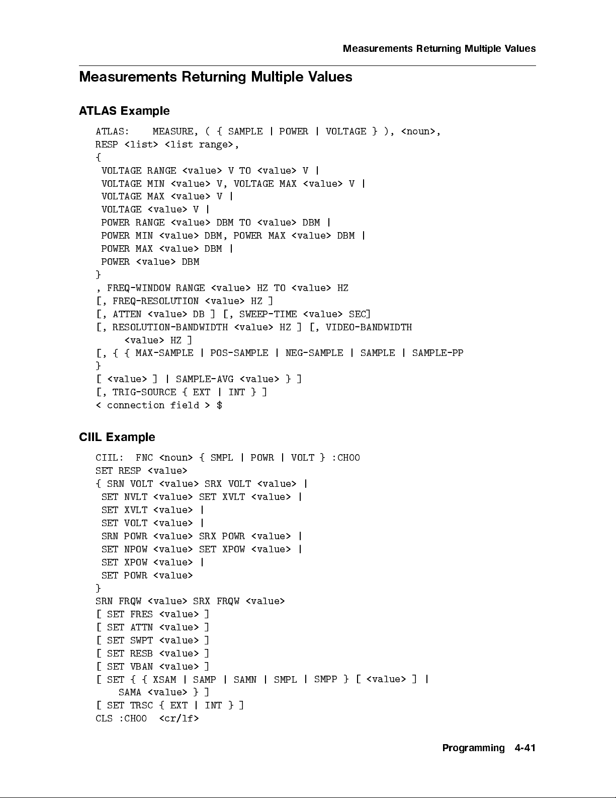
Measurements Returning Multiple Values
Measurements Returning Multiple Values
ATLAS Example
ATLAS: MEASURE, ( { SAMPLE | POWER | VOLTAGE } ), <noun>,
RESP <list> <list range>,
{
VOLTAGE RANGE <value> V TO <value> V |
VOLTAGE MIN <value> V, VOLTAGE MAX <value> V |
VOLTAGE MAX <value> V |
VOLTAGE <value> V |
POWER RANGE <value> DBM TO <value> DBM |
POWER MIN <value> DBM, POWER MAX <value> DBM |
POWER MAX <value> DBM |
POWER <value> DBM
}
, FREQ-WINDOW RANGE <value> HZ TO <value> HZ
]
FREQ-RESOLUTION
[,
[,
ATTEN
<value>
<value>
DB ]
[, RESOLUTION-BANDWIDTH
]
HZ
POS-SAMPLE
|
[,
<value>
MAX-SAMPLE
{
{
HZ
[, SWEEP-TIME
<value> HZ
NEG-SAMPLE
|
<value> SEC]
VIDEO-BANDWIDTH
[,
]
|
SAMPLE |
}
]
<value>
[
TRIG-SOURCE
[,
connection
<
SAMPLE-AVG
|
]
field
<value>
}
INT
|
EXT
{
$
>
}
]
SAMPLE-PP
Example
CIIL
|
SMPL
CIIL:
SET
SRN
{
RESP
VOLT
FNC
<value>
<noun>
<value>
{
SRX
VOLT
SET NVLT <value> SET XVLT <value> |
SET XVLT <value> |
SET VOLT <value> |
SRN POWR <value> SRX POWR <value> |
XPOW
NPOW
SET
SET XPOW
POWR
SET
<value>
<value>
<value>
SET
|
}
SRN FRQW <value> SRX FRQW <value>
[ SET FRES <value> ]
[ SET ATTN <value> ]
[ SET SWPT <value> ]
[ SET RESB <value> ]
[ SET VBAN <value> ]
SAMN
|
SAMP
|
XSAM
{
{
SET
[
]
[
CLS
SET
SAMA
TRSC {
:CH00
<value>
<cr/lf>
EXT
}
]
}
INT
|
|
POWR
<value> |
<value>
SMPL
|
VOLT
|
|
}
SMPP
:CH00
}
<value> ]
[
|
Programming
4-41
Page 77

Measurements Returning Multiple Values
INX { SMPL | POWR | VOLT } <cr/lf>
ATLAS Response
{ <value> |<error message text> } <cr/lf>
FTH { SMPL | POWR | VOLT } <cr/lf>
CIIL Response
{ <error message text> |
<amp 1 value>
<amp 2 value>
.
.
.
<amp N value> <cr/lf>
Note: N=RESP
OPN :CH00
[
RST <noun>
<cr/lf> ]
SMPL
{
|
POWR
|
VOLT
}
:CH00
<cr/lf>
4-42
Programming
Page 78

Setting Up a Conditioner
Setting Up a Conditioner
Sets up signal conditioner (receiver) to feed another measurement device.
ATLAS Example
ATLAS: SETUP, <noun>, { FREQ | POWER | VOLTAGE } ,
{ VOLTAGE RANGE <value> V TO <value> V |
VOLTAGE MIN <value> V, VOLTAGE MAX <value> V |
VOLTAGE MAX <value> V |
VOLTAGE <value> V |
POWER RANGE <value> DBM TO <value> DBM |
POWER MIN <value> DBM, POWER MAX <value> DBM |
POWER MAX <value> DBM |
POWER <value> DBM}
, FREQ-WINDOW RANGE <value> HZ TO <value> HZ
REF-OUT
,
[, ATTEN
RESOLUTION-BANDWIDTH
[,
[, {
<value>
<value>
HZ
{ MAX-SAMPLE
]
DB
]
POS-SAMPLE
|
SWEEP-TIME
[,
<value>
<value>
[,
]
HZ
NEG-SAMPLE
|
SEC]
VIDEO-BANDWIDTH
SAMPLE
|
|
SAMPLE-PP
}
]
<value>
[
TRIG-SOURCE
[,
connection
<
SAMPLE-AVG
|
]
field
<value>
}
INT
|
EXT
{
$
>
}
]
Example
CIIL
:CH00
CIIL:
SRN
{
FNC
VOLT
<noun>
<value>
MODF
SRX VOLT
<value> |
SET NVLT <value> SET XVLT <value> |
SET XVLT <value> |
SET VOLT <value> |
SRN POWR <value> SRX POWR <value> |
SET NPOW <value> SET XPOW <value> |
SET
SET
SRN
XPOW
POWR
FRQW
<value>
<value>
<value>
|
}
SRX
FRQW
<value>
SET REFO
[ SET ATTN <value> ]
[ SET SWPT <value> ]
[ SET RESB <value> ]
[ SET VBAN <value> ]
[ SET { { XSAM | SAMP | SAMN | SMPL | SMPP } [ <value> ] |
|
EXT
{
<cr/lf>
}
|
INT }
]
]
SAMA
TRSC
SET
[
CLS :CH00
:CH00
OPN
[
<value>
<cr/lf>
Programming
4-43
Page 79

Setting Up a Conditioner
RST <noun> { FREQ | POWR | VOLT } :CH00 <cr/lf>
4-44
Programming
Page 80

Setting Up Calibration Data
Setting Up Calibration Data
This example sets up amplitude/frequency calibration data for accuracy enhancementofthe
measurement device (path loss correction.)
ATLAS Example
ATLAS: SETUP, CALIBRATION , POWER ,
FREQUENCY <value>, POWER-DIFF <value>,
.
. (up to twenty pairs of calibration data may be sent)
.
FREQUENCY <value>, POWER-DIFF <value>
$
Example
CIIL
:CH00
POWR
CAL
FREQ
FNC
<value>
SET
PRDF
<value>
CIIL:
SET
.
.
.
SET
FREQ
<value>
SET
<value>
PRDF
<cr/lf>
Note
frequency/amplitude
The
frequency
est
w
lo
rst.
pairs
MUST
b
in
t
sen
e
An alternative form (for convenience of the ATLAS programmer):
FNC CAL POWR :CH00
SET FREQ <value> <value> <value> .. <value> <value>
SET PRDF <value> <value> <value> .. <value> <value>
<cr/lf>
order
in
hed
matc
e
Note
the
case,
this
In
equal n
umber of v
be in ascending
ys will
arra
alues m
frequency order|lo
b
ust b e receiv
west frequency rst.
ed for FREQ and
ascending
one-to-one
a
on
basis.
order|
An
frequency
PRDF. The data m
ust
Programming
4-45
Page 81

Implemented Nouns and Noun-modifiers
Table 4-1. Corresponding Atlas and CIIL Nouns
Atlas Nouns CIIL Nouns
AC SIGNAL ACS
AM SIGNAL AMS
calibration CAL
DME DME
DOPPLER DOP
FM SIGNAL FMS
IFF IFF
ILS ILS
dulation)
(Pulsed
AM
P
SIGNAL
PM
PULSED
PULSED
Amplitude
SIGNAL
C
A
TRAIN
C
A
Mo
AM
P
PMS
C
A
P
T
A
P
RANDOM
CAR
SUP
CAN
A
T
OR
V
VEFORM
WA
NOISE
SIGNAL
RDN
SCS
C
A
T
OR
V
WA
V
4-46
Programming
Page 82

Table 4-2. Corresponding Atlas and CIIL Noun Modifiers
Atlas Modiers CIIL Mo diers
and<value>Units
am-freq AMFQHZ
AM-SHIFT AMSH DEG
AMP-MOD AMOD PC
AMPL-MOD-C AMMC PC
AMPL-MOD-F AMMF PC
ATTEN ATTN DB
BANDWIDTH BAND HZ
CAR-AMPL CAMP V
CAR-FREQ CFRQHZ
DDM DDMD ratio
A
QW
HZ
HZ
HZ
HZ
HZ
HZ
HZ
HZ
HZ
DOMINANT-MOD-SIG DMDS
FREQ FREQ
FM-COMP FMCP
freq-ref FREF
freq-resolution FRES
freq-start FST
freq-step FSTE
freq-stop FSTO
FREQ-WINDO
W
FR
HI-MOD-FREQ HMDF HZ
LO-MOD-FREQ LMDF HZ
Programming
4-47
Page 83

Table 4-2. Corresponding Atlas and CIIL Noun Modifiers (continued)
Atlas Modiers CIIL Modiers
and<value>Units
max-power XPOWDBM
max-sample XSAM integer
MAX-TIME MAXT SEC
max-voltage XVLTV
MEAN-MOD MMOD PC
min-power NPOWDBM
min-voltage NVLTV
MOD-AMPL MAMP V
MOD-FREQ MODF HZ
neg-sample SAMN integer
V/sqrt(HZ)
NOISE-AMPL-DENS NO
AD
SEC
WR
O
DBM/HZ
PC
integer
DBM
DB
DBM
alue
v
no
NOISE-PWR-DENS NOPD
p
PERM
d
t-mo
ercen
PERIOD PERI
os-sample
p
WER
PO
WER-DIFF
PO
WER-REF
PO
SAMP
PO
PRDF
PREF
ref-out REF
resolution-bandwidth RESB HZ
RESP RESP integer
RMS-VOLT RMSV V
SAMPLE SMPL in
sample-a
vg
SAMA
teger
in
teger
eld
4-48
Programming
Page 84

Table 4-2. Corresponding Atlas and CIIL Noun Modifiers (continued)
Atlas Modiers CIIL Modiers
and<value>Units
sample-pp SMPP integer
SAMPLE-WIDTH SMPW SEC
signal-threshold SGTH DBM
signal-search SIGS DBM
spectrum SPEC DBM
SUB-CAR-FREQ SBCF HZ
SUB-CAR-MOD SBCM PC
sweep-time SWPT SEC
trig-level TRLVV
trig-source TRSC literal string
video-bandwidth VBAN
AGE
T
OL
V
GE-P
A
T
OL
V
T
OL
V
VLPK
HZ
V
V
Programming
4-49
Page 85

Page 86

5
Troubleshooting
This chapter provides troublesho oting information including information on the module's self
test, the error indicators, and error co des. A module's block diagram is lo cated at the end
of this chapter. Additional troublesho oting information can be found in the HP 71000A/C
Modular Spectrum Analyzer Installation and Verication Manual.
Service Accessories
Module Service Extender . . . . . . . . . . . . . . . . . .............. HP Part Number 70001-60013
70900-60058
er
b
Num
art
P
HP
.
.
.
.
.
.
.
.
..
..
..
..
.
.
.
.
.
.
.
.
.
.
.
.
.
.
.
.
.
..
..
Board Extender
Connector
Pin
..
Straigh
tener
5021-7445
er
b
Num
art
P
HP
.
.
.
.
.
.
.
.
.
..
..
..
..
.
.
.
.
.
.
.
.
.
.
.
.
.
.
Front-P
the
k
Chec
assign
to
cedure
pro
anel
HP-MSIB
displa
the
Chapter
in
Operation
Address
eyb
k
and
y
2.
Matrix to
to
oard
ensure
the
lo
cal
the
that
oscillator
system
dule.
mo
congured
is
Refer
to
prop
installation
the
erly
sure
Be
.
Troubleshooting
5-1
Page 87
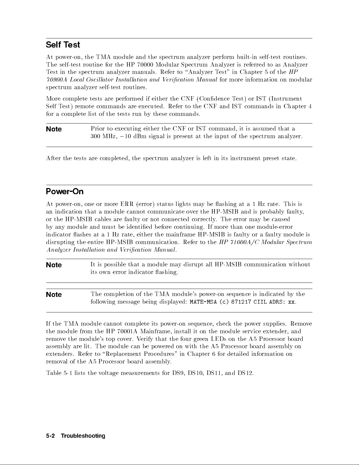
Self Test
Atpower-on, the TMA module and the sp ectrum analyzer perform built-in self-test routines.
The self-test routine for the HP 70000 Modular Spectrum Analyzer is referred to as Analyzer
Test in the spectrum analyzer manuals. Refer to \Analyzer Test" in Chapter 5 of the
70900A Local Oscil lator Instal lation and Verication Manual
for more information on modular
HP
spectrum analyzer self-test routines.
More complete tests are performed if either the CNF (Condence Test) or IST (Instrument
Self Test) remote commands are executed. Refer to the CNF and IST commands in Chapter 4
for a complete list of the tests run by these commands.
Note
Prior to executing either the CNF or IST command, it is assumed that a
300 MHz,010 dBm signal is present at the input of the sp ectrum analyzer.
After the tests are completed, the spectrum analyzer is left in its instrument preset state.
er-On
w
o
P
caused
e
dular
This is
faulty
mo
y
Spe
dule
without
er-on,
w
o
p
t
A
indication
an
HP-MSIB
the
or
ymo
an
y
b
indicator
disrupting
nalyzer
A
Note
Note
one
that
dule
ashes
the
Instal
or
cables
and
at
tire
en
lation
It
its
more
mo
a
ust
m
Hz
1
a
HP-MSIB
and
ossible
p
is
wn
o
ERR
dule
are
e
b
rate,
V
error
(error)
cannot
y
fault
tied
iden
either
comm
ation Manual
eric
a
that
indicator
comm
not
or
b
the
unication.
dule
mo
ashing.
status
unicate
connected
con
efore
mainframe
ma
ligh
.
y
ma
ts
er
v
o
correctly.
uing.
tin
HP-MSIB
Refer
disrupt
e
b
y
HP-MSIB
the
If
the
to
all
ashing
The
more
HP
HP-MSIB
at
and
ma
error
one
than
y
fault
is
71000A/C
comm
probably
is
b
y
mo
a
or
Mo
unication
dule-error
fault
Hz rate.
1
a
The completion of the TMA module's power-on sequence is indicated bythe
following message being displayed:
MATE-MSA (c) 871217 CIIL ADRS: xx
,
is
ctrum
.
complete
70001A
ver. V
the
cannot
HP
If
the
the
mo
TMA
dule
module
from
remove the module's top co
assembly are lit.
The mo dule can b e po
extenders. Refer to \Replacemen
removal of
Table 5-1 lists the v
5-2
the A5 Pro cessor board assem
oltage measuremen
Troubleshooting
w
o
p
its
Mainframe,
er-on
install
sequence,
the
it on
c
hec
mo
the p
k
dule
er
w
o
service
supplies.
extender,
Remo
and
erify that the four green LEDs on the A5 Pro cessor b oard
wered on with the A5 Pro cessor b oard assem
bly on
t Procedures" in Chapter 6 for detailed information on
bly.
DS9, DS10, DS11, and DS12.
ts for
e
v
Page 88

Table 5-1. A5 Processor Test Point Measurements
LED Test Point Voltage
DS9 TP18 +12 V
DS10 TP19
DS11 TP17
0
0
5.2 V
12 V
DS12 TP16 +5 V
Error Codes
Errors must be queried remotely by using the STA (Status) command which requests the
current operation status. Following is a list of all the p ossible error co des and corresp onding
messages.
Timeout
F05ASA
F07ASA
F07ASA
F07ASA
F07ASA
CHARA
F07ASA
CHARA
F07ASA
(MOD)
(MOD)
(MOD)
(MOD)
(MOD)
Measuremen
CI
HARD
INV
INV
CTERISTIC
(MOD)
UNRECOGNIZED
CTERISTIC
(MOD)
CNF/IST
IL/HPIB
ALID
ALID
t
tax
Syn
ARE Error
W
RESPONSE
MEASUREMENT
MEASUREMENT
Error:
HHHH
Error
LENGTH
,M
g
f
g
N
,
.
.
.
,N
f
more
or
F
Chapter
information
4.
on
the
error
messages,
refer
to
the
ST
command
A
description
in
Troubleshooting
5-3
Page 89

Page 90

6
Assembly Replacement
Due to the simplicity of mo dule design, no replacement procedures are provided. Instead, this
chapter supplies a wire routing diagram for Option H72 modules (Option H69 modules do not
require wire routing information.) Table 6-2 lists the hardware torque values for Option H72
modules. Table 6-2 can also be used to determine torque values for Option H69. In addition
to the required hand tools listed in Table 6-1, you'll need torque wrenches covering the values
in Table 6-2.
Caution
Caution
This module contains static-sensitive components. Read the electrostatic
discharge information in Chapter 1 b efore removing anyassemblies.
rigid
semi-
y
b
oth
an
ends
the
of
hance
c
y
an
of cable
When
cables.
replacing
Before
semi-rigid
cable
an
remo
attac
assem
ving
hed
bly
an
to
oid
v
a
,
assem
the
b
bly
assem
ending
alw
,
bly
a
.
ys
This
distorting
or
osen
lo
reduces
damage.
ools
T
er
wrenc
Hand
HP
h
Num
art
P
8710-0978
8710-0899
8710-0012
8710-0030
8720-0015
er
b
6-1.
able
T
ol
o
T
Phillips screwdriv
pliers
com
e
bination
ozi-driv
P
Small
cutter
Wire
Long-nose
5/16-inc
h
Required
#0
er
screwdriv
5/8-inch open-end wrench 8720-0010
7-mm combination wrench 8710-1258
Assembly
Replacement
6-1
Page 91

Figure
6-1.
H72 Wire
Routing
Diagram
6-2
Assembly
Replacement
Page 92

alues
able
T
6-2.
orque
T
V
Item Description T
1 Screws
2 Screws
3 Nuts
4 Nut
securing
5 Nuts
6 SMA
7 Screws
8 Spring
securing b
securing
securing
securing
connections
cable
securing
Grounding
oard assem
frame
connectors
N
connector
BNC
rear-panel
S1
Screws
blies
parts
connectors
Pozi-driv
small
P
small
5/8-inc
7/16 75
1/4-inc
5/16-inc
P
small
P
small
Size
ol
o
ozi-driv
h
h
h
ozi-driv
ozi-driv
orque
T
e
e
IN-LB
6
IN-LB
6
75
IN-LB
IN-LB
IN-LB
6
IN-LB
10
e
e
IN-LB
6
IN-LB
6
Assembly
Replacement
6-3
Page 93

Page 94

7
Replaceable Parts
This section contains information for ordering replacement parts. The parts list documents all
assembly versions produced up to the time that the manual is printed.
Replaceable Parts List Format
The following information is listed for each part:
1. The Hewlett-Packard part number.
(CD).
digit
k
hec
c
er
b
um
2. The
3.
4.
5.
part n
description
The
v
A
man
The
e-digit
ufacturer
co
de
part.
the
of
indicating
part
n
um
a
b
ypical man
t
er.
ufacturer of
the
part.
Replaceable
P
arts
7-1
Page 95
Ordering Information
To order a part listed in the replaceable parts table, quote the Hewlett-Packard part number,
include the check digit, and indicate the quantity required. Address and mail the order to
the HP Sales and Service Oce nearest you. The check digit ensures accurate and timely
processing of your order.
To order a part that is not listed in the replaceable parts table, include the mo del number
of the mo dule, the function and description of the part, and the number of parts required.
Address and mail the order to the HP Sales and Service Oce nearest you.
Direct Mail Order System
In the USA, Hewlett-Packard can supply parts through a direct mail order system.
Advantages of using the system are as follows:
Direct ordering and shipment from the HP Parts Center in Mountain View, California.
when
ecic
sp
um
parts
t
the
maxim
No
order
orders
Prepaid
in
No
hec
c
A
ordering
Direct
um
quan
require
transp
oices.
v
money
or
k
information
Phone-Order
A phone-order
tity
system
minim
or
imposed
billing
ortation.
order
are
um
on orders
and
ust
m
v
a
v
a
is
tit
quan
oicing.)
v
in
(There
is
accompan
ailable
from
System
ailable
within
requirement
y
made through
handling
a
y
HP
the
c
direct
Sales
U.S.A.
on an
the
harge
mail
and
y mail
HP
added
orders.
Service
regular
for
order. (There
and
Sales
eac
to
Mail
Oces.
and
Service
order.)
h
order
hotline
is
Oces
and
forms
replacemen
minim
a
service. Hewlett-Packard has provided a toll-free telephone number, and accepts Mastercard
or Visa for orders.
Regular Orders
p.m.
5
to
a.m.
6
The toll-free
time),
acic
(P
telephone
Monda
um
n
through
y
227-8164.
(800)
is
er
b
Regular
.
y
Frida
It
orders
require
ailable
av
is
from
four-da
a
y
deliv
ery
time.
Hotline Orders
The hotline service for ordering
year. There is an additional c
harge on hotline orders to co
handling.
Monda
968-2347.
arts
P
telephone
through
y
Hotline
The
acic
(P
holida
7-2
toll-free
hotline
time),
(415)
is
ys
Replaceable
emergency parts is a
227-8164,
(800)
is
er
b
um
n
telephone
The
.
y
rida
F
normally
orders
are
vailable 24 hours a da
ver the cost
ailable
v
a
er for
b
um
n
delivered
of freight and special
6
from
after-hours,
follo
the
y,365da
to
a.m.
eek
w
business
wing
ys a
p.m.
5
ends,
da
and
.
y
Page 96

Table 7-1. Reference Designations, Abbreviations and Multipliers
REFERENCE DESIGNATIONS
A Assembly F Fuse RT Thermistor
ATAttenuator, Isolator, FL Filter S Switch
Limiter, Termination HY Circulator T Transformer
B Fan, Motor J Electrical Connector TB Terminal Board
BT Battery (Stationary Portion), TC Thermo couple
C Capacitor Jack TP Test Point
CP Coupler K Relay U Integrated Circuit,
CR Dio de, Dio de L Coil, Inductor Microcircuit
Thyristor, Step M Meter V Electron Tube
Recovery Diode, MP Miscellaneous VR Breakdown Dio de
Varactor Mechanical Part (Zener),
DC Directional Coupler P Electrical Connector Voltage Regulator
DL Delay Line (Movable Portion), W Cable, Wire, Jump er
DS Annunciator, Lamp, Plug X Socket
Emitting
Light
de (LED),
Dio
Signaling
Device
(Visible) T
Miscellaneous
E
Electrical
P
Q Silicon
art
R
Rectier
T
Resistor
Controlled
ransistor,
Th
de
rio
(SCR),
yristor
Y Crystal
(Piezo
Quartz)
uned
T
Z
uned
T
Unit
electric,
vit
Ca
Circuit
,
y
Replaceable
P
arts
7-3
Page 97

Table 7-1. Reference Designations, Abbreviations and Multipliers (continued)
REFERENCE DESIGNATIONS
A
BSC Basic CNDCT Conducting,
BTN Button Conductive,
A Across Flats, Acrylic, Conductivity,
Air (Dry Method),
C
Conductor
Ampere CONT Contact,
ADJ Adjust, Adjustment C Capacitance, Continuous,
ANSI American National Capacitor, Control,
Standards Institute Center Tapped, Controller
(formerly Cermet, Cold, CONV Converter
USASI-ASA) Compression CPRSN Co mpression
ASSY Assembly CCP Carbon Composition CUP-PT Cup Point
AWG American Wire Gage Plastic CW Clockwise,
CD Cadmium, Card, Continuous Wave
B
BCD Binary
Decimal CHAR
G
Board,
Beryllium
e
yp
T
Bearing,
Brass
BD
BE-CU
BNC
BR
BRS
ded
Co
Bundle
Copp
Connector
of
Boring
CER
CHAM Chamfer
er
CMOS
Cord
Ceramic
Character,
Characteristic,
Charcoal D
Complemen
Metal
tary
Oxide
Semiconductor D
D
Depletion,
Deep,
Depth,
Direct
A
Darlington
Diameter,
Curren
t
7-4
Replaceable
P
arts
Page 98

Table 7-1. Reference Designations, Abbreviations and Multipliers (continued)
REFERENCE DESIGNATIONS
DAP-GL Diallyl Phthalate FT CurrentGain JFET Junction Field
Glass Bandwidth Product Eect Transistor
DBL Double (Transition
DCDR Deco der Frequency), Feet,
K
DEG Degree Foot
D-HOLE D-Shaped Hole FXD Fixed K Kelvin, Key,
DIA Diameter Kilo, Potassium
DIP Dual In-Line Package
G
KNRLD Knurled
DIP-SLDR Dip Solder KVDC Kilovolts
D-MODE Depletion Mode GEN General, Generator Direct Current
DO Package Type GND Ground
Designation GP General Purpose,
L
DP Deep, Depth, Dia- Group
metric Pitch, Dip LED Light Emitting
Three
ole
DP3T
DPDT
WL
D
E-R
EXT
Double
Thro
Double
Thro
Do
E
E-Ring
Extended, Extension,
External,
F
P
w
Double
ole
P
w
ell
w
H
HD
HEX
H
Henry
Hardware
W
Hexadecimal,
,
High
LG
LIN
LK
LK
G
Hexagon, LUM
de
Dio
Length,
Linear,
Link,
Leak
Linearit
Loc
age,
Luminous
Long
k
Lo
king
c
y
Hexagonal
HLCL
HP
Extinguish
Helical
Hewlett-P
Compan
I
y,
k
ac
High
ard
M
ass
P
Mil,
um,
Milli,
M
Male,
Mega,
de
Mo
Maxim
IC Collector Current, MA Milliampere
F Fahrenheit, Farad, Integrated Circuit MACH Machined
Female, Film ID Identication, MAX Maximum
(Resistor), Fixed, Inside Diameter MC Molded Carbon
t,
requency
on
F
Film/
IF
Flange,
C
F
Carb
orward
F
termediate
In
Curren
MET
Comp
Metal,
osition
Metallized
Composition, Edge Frequency MHZ Megahertz
of Cuto F
requency,
IN Inch
MINTR Miniature
Face INCL Including MIT Miter
FDTHRU Feedthrough
INT Integral, In
tensity,
MLD Mold, Molded
FEM Female Internal MM Magnetized Material,
FIL-HD Fillister Head Millimeter
Fluid
FL
T-PT
FLA
FR
FREQ
Flash,
P
Flat
t
ron
F
requency
F
Flat,
oin
J
t
J-FET
Junction
Eect
Field
ransistor
T
MOM
MTG
MTLC
MW
Momen
Moun
Metallic
Milliw
tary
ting
att
Replaceable
P
arts
7-5
Page 99

Table 7-1. Reference Designations, Abbreviations and Multipliers (continued)
REFERENCE DESIGNATIONS
N
PLSTC Plastic SMA Subminiature,
PNL Panel ATyp e (Threaded
N Nano, None PNP Positive Negative Connector)
N-CHAN N-Channel Positive (Transistor) SMB Subminiature,
NH Nanohenry POLYC Polycarbonate BType (Slip-on
NM Nanometer, POLYE Polyester Connector)
Nonmetallic POT Potentiometer SMC Submi niature,
NO Normally Open, POZI Pozidriv Recess C-Type (Threaded
Number PREC Precision Connector)
NOM Nominal PRP Purple, Purp ose SPCG Spacing
NPN NegativePositive PSTN Piston SPDT Single Pole
Negative(Transistor) PT Part, Point, Double Throw
NS Nanosecond, Pulse Time SPST Single Pole
NUM
NYL
OA
OD
OP
OPT
Non-Shorting,
Nose
Numeric
Nylon (P
olyamide)
O
er-All
Ov
Diameter
erational
AMP
Outside
Op
Amplier R
Optical,
Option,
Optional Righ
P
Width
PW
Pulse
Q
SQ
SST
STL
Single
Square
Stainless Steel
Steel
SUBMIN Subminiature
Merit
Q
Figure
of
SZ
Size
R
t,
Red,
Ring
Resistor,
T
eeth,
T
T
T
emp
REF
Range,
Resistance,
Reference
RES Resistance, Resistor Thickness, Time,
Thro
eratu
w
re,
RF Radio Frequency Timed, Tooth,
PA Picoamp ere, Power RGD Rigid Typical
Amplier RND Round TA Ambient
PAN-HD
AR
P
PB
Pan Head
arallel,
P
(Metal),
Lead
P
arit
Pushbutton
PC
Printed Circuit
PCB Printed Circuit
Board Wave Resonator
RR Rear Temp
y
R
VT
Riv
et,
Riv
eted
TC
S
THD
SAWR Surface Acoustic
THK Thick
TO Package T
erature,
talum
an
T
erature
emp
T
Coe cien
t
Thread, Threaded
ype
P-CHAN P-Channel SEG Segment Designation
PD Pad, Power SGL Single TPG Tapping
Head
russ
T
rimmer
T
urn,
T
orsion
T
T
urns
PF
PK
Dissipation SI
er
w
o
age
P
SL
SL
Picofarad,
actor
F
k
ac
G
P
Silicon,
h
Square
Slide,
Slot,
T
Inc
w
Slo
Slotted
TR-HD
TRMR
TRN
TRSN
7-6
Replaceable
P
arts
Page 100

Table 7-1. Reference Designations, Abbreviations and Multipliers (continued)
REFERENCE DESIGNATIONS
U
VAR Variable
Y
VDC Volts|Direct Current
UCD Microcandela YIG Yttrium-Iron-
UF Microfarad Garnet
UH Microhenry
W
UL Microliter,
Underwriters' W Watt, Wattage,
Z
Laboratories, Inc. White, Wide, Width
UNHDND Unhardened W/SW With Switch ZNR Zener
WW Wire Wound
V
X
V Variable, Violet,
Volt, Voltage X By (Used with
olts|
acuum,
C
A
V
V
Alternating
V
Curren
t
T
able
Dimensions),
Reactance
Multipliers
7-2.
Abbreviation
Prex
T
G
M
giga
mega
k
da
dek
d
c centi 10
MUL
Multiple
tera
10
10
10
kilo 10
a
10
deci 10
TIPLIERS
12
9
6
3
2
1
0
0
2
Abbreviation
m
n
p
f
a
Prex
milli
micro
nano
pico 10
to
fem
atto 10
Multiple
3
0
10
6
0
10
9
0
10
12
0
15
0
10
18
0
Replaceable
P
arts
7-7
 Loading...