

Page 1

Agilent 71708A Microwave Source
Agilent 70428A Microwave Source Module
Data Sheet
Variable frequency source with lowest phase noise
Page 2
2
The Agilent Technologies 71708A
microwave source provides signals
with exceptionally low phase and AM
noise performance from 2.4 to 26.4 GHz.
Phase noise specifications are
–113 dBc/Hz and –125 dBc/Hz at
1 kHz and 10 kHz offsets from a
10.2 GHz carrier. AM noise is as low
as –150 dBc/Hz. Thus, the 71708A is
an ideal source for testing microwave
receivers, verifying noise floors of
phase noise measurement systems, or
substituting for the local oscillator in
radar systems.
The 71708A consists of a
4
/8 width
70428A microwave source module
and an 70004A color display/mainframe.
This system combines:
• Low phase noise
• Low AM noise
• Output frequency range from
2.4 to 26.4 GHz
• 600 MHz frequency resolution
• Optional 0.1 Hz frequency resolution
• Output power up to +16 dBm
Modular Measurement System (MMS)
building block
The user interface of the 71708A is
built into the firmware of the 70428A
microwave source module. This
allows you to easily integrate the
70428A into existing MMS systems
with multiple instruments. Through
the MMS user interface, you have
complete control of all its functions.
Some of these functions include:
• Output frequency
• Output power level
• Reference source configuration
• Calibration functions
• Tuning sensitivity
In addition to manual operation, all
functions can be controlled over GPIB
by a computer.
0.1 Hz frequency resolution
For applications that demand frequency
resolution finer than 600 MHz, add
Option 002 and an Agilent 8662A/3A
synthesized signal generator. This
combination of instruments provides
a signal from 2.4 GHz to 26.5 GHz
with 0.1 Hz frequency resolution
while preserving much of the low
noise performance of the 71708A.
With Option 002, simply enter the
desired output frequency and the
71708A automatically sets the frequency
of its internal microwave source and,
over GPIB, the frequency and power
of the 8662A/3A.
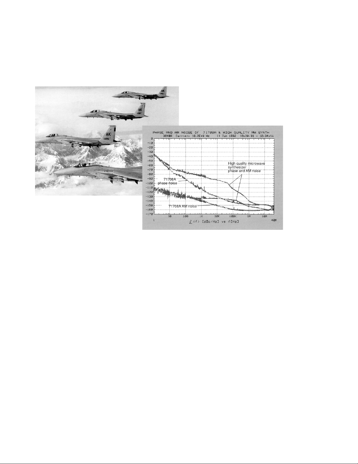
Typical phase and AM noise of the Agilent 71708A microwave source
and high quality microwave synthesizer
Courtesy of McDonnell Douglas
Page 3

3
Selectable tuning and phase noise
performance
Along with low phase noise, the
71708A provides a DC coupled tuning
port with three sensitivity settings.
This allows you to phase-lock the
71708A when using it as a reference
source for phase noise measurements
on synthesized sources. The three
tuning sensitivity settings are directly
coupled to noise performance and
allow the 71708A flexibility to adapt
to your measurement needs.
Built-in output power calibration
Periodic calibration of the output
power of the 71708A can be quickly
and easily performed using built-in
calibration functions and an external
power meter. Over GPIB, the microwave
source will automatically control an
Agilent 437B, 438A,or 70100A power
meter. Over MSIB, the 71708A will
automatically control the 70100A.
Microwave receiver noise measurements
In the past, measuring the noise of
microwave receivers required two
receivers driven by a common
microwave source. This was due to
the inadequate phase and AM noise
performance of the available
microwave sources. Using this
method, the noise of the microwave
source cancels out and the combined
noise of the two receivers can be
measured. However, it is difficult to
accurately determine the noise of
each of the individual receivers and
two receivers are required.
With the low phase and AM noise of
the 71708A and a 3048A phase noise
measurement system, this measurement can be made directly. By driving
the input of the microwave receiver
with the low noise 71708A, the noise
of the IF signal out of the receiver is
dominated by the noise of its
microwave conversion and IF processing components. The noise of the
IF signal can then be measured using
an RF reference source such as the
8662A, and the resulting absolute
noise of the microwave receiver measured directly.
Low AM noise
Low AM noise allows the 71708A to
be used as a source for AM noise
measurements of signal processing
components such as amplifiers and
mixers. This low AM noise performance minimizes the degradation of
residual PM measurements due to AM
to PM conversion in the device under
test or in the microwave phase detector.
Reference chain
The heart of the 71708A microwave
source is the reference chain which
consists of a 10 MHz crystal oscillator, 100 MHz oscillator, and 600 MHz
oscillator. Each of these oscillators
can be the primary reference, providing three different tuning sensitivities
with corresponding phase noise performance.
The 600 MHz signal from the reference chain is multiplied with a step
recovery diode which generates harmonics from 2.4 to 26.4 GHz. To
obtain a particular harmonic, this signal is filtered with a YIG tuned filter.
A variable gain GaAs amplifier boosts
the power of this signal.
Microwave receiver
Block diagram for microwave receiver noise measurements
Agilent 70428A microwave source block diagram
IF out
Reference
oscillator
Tune line "in"
600
MHz
SRD YTF
µ wave amp
µ wave LO "out"
8662A "in"
YTF
Option 002 only
µ wave amp
RF "out"
71708A E5500 SeriesReference source
Page 4

4
Configuration 1
All oscillators locked
• For those applications that demand
the lowest possible noise at all
offsets
• Tuning sensitivity of 0.05 ppm/volt
• Phase noise of –65 dBc/Hz at
10 Hz offset, –113 dBc/Hz at 1 kHz
offset and 10 GHz carrier frequency
Configuration 2
100 MHz and 600 MHz oscillators locked
• For those applications that require
the best phase noise >1 kHz and a
moderate tuning range
• Tuning sensitivity of 1 ppm/volt
• Phase noise of –33 dBc/Hz at 10 Hz
offset, –113 dBc/Hz at 1 kHz offset
and 10 GHz carrier frequency
Configuration 3
600 MHz free-running oscillator
• For those applications that require
a wide tuning range and a low
broadband noise floor
• Tuning sensitivity of 20 ppm/volt
• Phase noise of –20 dBc/Hz at 10 Hz
offset, –100 dBc/Hz at 1 kHz offset
and 10 GHz carrier frequency
Option 002
Option 002 of the 71708A adds the
capability to mix the internal microwave
source with an external RF source.
This option adds a microwave mixer,
a second YIG tuned filter, a second
GaAs amplifier, and associated signal
switching. Once the first YIG tuned
filter is tuned and the RF source frequency and power set, the second YIG
tuned filter is tuned to the correct
frequency. The variable gain GaAs
amplifier provides output power control of this composite signal.
10 MHz
100 MHz
PLL PLL
PLL BW
25 Hz - 10 kHz
Tune line
1 kHz - 30 kHz
PLL BW
600 MHz
To
Multiplier
10 MHz
PLL
PLL BW
25 Hz - 10 kHz
10 MHz 100 MHz
PLL
PLL BW
25 Hz - 10 kHz
100 MHz
Tune line
Tune line
PLL
PLL BW
1 kHz - 30 kHz
PLL
PLL BW
1 kHz - 30 kHz
600 MHz
To
Multiplier
600 MHz
To
Multiplier
Page 5

5
• Output power up to +16 dBm provides sufficient drive level for your
test applications
• Adding Option 002 and an
8662A/3A extends the superior
noise performance with 0.1 Hz
frequency resolution from 2.4 GHz
to 26.5 GHz
• 10 MHz crystal, 100 MHz and
600 MHz oscillator outputs on rear
panel
• Low AM noise is ideal for microwave
residual measurements
• MMS user interface and modular
functionality integrates easily into
existing MMS systems
• Low phase noise yields state-ofthe-art microwave receiver measurement capability
• Variable tuning sensitivity allows
you to optimize the noise performance for your application
Page 6

6
Microwave source
RF output
Frequency range 2.4 GHz to 25.8 GHz
Frequency resolution 600 MHz
Output power
2.4 to 6.6 GHz 0 to +16 dBm
7.2 to 25.8 GHz 0 to +10 dBm
Spectral purity
The internal reference oscillators can
be locked together in three configurations, each with different phase noise
performance and tuning bandwidths.
All noise levels are in units of dBc/Hz
unless otherwise noted. Spurious and
phase noise specifications at any offset can be determined by drawing a
line, on a log-log plot between specification points given.
Best phase noise <100 Hz frequency offsets — narrow tuning sensitivity
1. All noise levels above –30 dBc/Hz are 3 dB below S φ(f) expressed in dB with respect to 1 rad2/Hz.
Agilent 71708A/70428A
Specifications
Specifications describe the instrument’s warranted performance and apply after a 30 minute warm-up. These specifications are valid over its operating/environmental range unless otherwise noted.
Supplemental Characteristics (shown in italics) are intended to provide additional information, useful in applying the
instrument by giving typical (expected), but not warranted performance parameters. These characteristics are shown
in italics or labeled as “typical,” “usable to,” or “nominal.”
Configuration 1. All oscillators locked
Customer
tune range:
±.25 ppm
10 MHz
100 MHz
600 MHz
Output frequency
2.4 to 3.0 GHz
3.0 to 4.2 GHz
4.2 to 6.0 GHz
6.0 to 7.8 GHz
7.8 to 10.2 GHz
10.2 to 12.6 GHz
12.6 to 18.0 GHz
18.0 to 25.8 GHz
1
1
10 100 1k 10k 100k 1M 10M 40M ≥1k
–50 –80 –100 –128 –138 –148 –152 –152 –152 –60 –80
Typ.
–45 –75 –95 –123 –133 –143 –147 –147 –147 –50 –70
Spec.
–47 –77 –97 –125 –136 –146 –150 –150 –150 –54 –80
Typ.
–42 –72 –92 –120 –131 –141 –145 –145 –145 –44 –70
Spec.
–44 –74 –94 –122 –134 –144 –148 –148 –148 –54 –80
Typ.
–39 –69 –89 –117 –129 –139 –143 –143 –143 –44 –70
Spec.
–42 –72 –92 –120 –132 –143 –147 –147 –147 –54 –80
Typ.
–37 –67 –87 –115 –127 –138 –142 –142 –142 –44 –70
Spec.
–40 –70 –90 –118 –130 –141 –145 –145 –145 –50 –80
Typ.
–35 –65 –85 –113 –125 –136 –140 –140 –140 –40 –70
Spec.
–38 –68 –88 –116 –128 –140 –143 –143 –143 –50 –80
Typ.
–33 –63 –83 –111 –123 –135 –138 –138 –138 –40 –70
Spec.
–35 –65 –85 –113 –125 –137 –140 –140 –140 –47 –70
Typ.
–30 –60 –80 –108 –120 –132 –135 –135 –135 –37 –60
Spec.
–32 –62 –82 –110 –122 –134 –136 –136 –136 –44 –70
Typ.
–27 –57 –77 –105 –117 –129 –131 –131 –131 –34 –60
Spec.
Offset from carrier (Hz)
Spurious
(dBc)
10 to
100
Page 7

7
Better phase noise <10 kHz frequency offsets — moderate tuning sensitivity
Good phase noise <10 kHz frequency offsets — wide tuning sensitivity
1. All noise levels above –30 dBc/Hz are 3 dB below S (f) expressed in dB with respect to 1 rad2/Hz.
2. All noise levels above –40 dBc/Hz are 3 dB below S (f) expressed in dB with respect to 1 rad
2
/Hz
Configuration 2. 100 and 600 MHz oscillators locked
Configuration 3. 600 MHz free running oscillator
Customer
tune range:
±5 ppm
10 MHz
100 MHz
600 MHz
Output frequency
2.4 to 3.0 GHz
3.0 to 4.2 GHz
4.2 to 6.0 GHz
6.0 to 7.8 GHz
7.8 to 10.2 GHz
10.2 to 12.6 GHz
12.6 to 18.0 GHz
18.0 to 25.8 GHz
1
1
+2 –48 –98 –128 –138 –148 –152 –152 –152 –60 –80
Typ.
+7 –43 –93 –123 –133 –143 –147 –147 –147 –50 –70
Spec.
+5 –45 –95 –125 –136 –146 –150 –150 –150 –54 –80
Typ.
+10 –40 –90 –120 –131 –141 –145 –145 –145 –44 –70
Spec.
+8 –42 –92 –122 –134 –144 –148 –148 –148 –54 –80
Typ.
+13 –37 –87 –117 –129 –139 –143 –143 –143 –44 –70
Spec.
+10 –40 –90 –120 –132 –143 –147 –147 –147 –54 –80
Typ.
+15 –35 –85 –115 –127 –138 –142 –142 –142 –44 –70
Spec.
+12 –38 –88 –118 –130 –141 –145 –145 –145 –50 –80
Typ.
+17 –33 –83 –113 –125 –136 –140 –140 –140 –40 –70
Spec.
+14 –36 –86 –116 –128 –140 –143 –143 –143 –50 –80
Typ.
+19 –31 –81 –111 –123 –135 –138 –138 –138 –40 –70
Spec.
+17 –33 –83 –113 –125 –137 –140 –140 –140 –47 –70
Typ.
+22 –28 –78 –108 –120 –132 –135 –135 –135 –37 –60
Spec.
+20 –30 –80 –110 –122 –134 –136 –136 –136 –44 –70
Typ.
+25 –25 –75 –105 –117 –129 –131 –131 –131 –34 –60
Spec.
2
10
100 1k 10k 100k 1M 10M 40M 21k
Offset from carrier (Hz)
Spurious
(dBc)
10 to
100
Customer
tune range:
±100 ppm
10 MHz
100 MHz
600 MHz
Output frequency
2.4 to 3.0 GHz
3.0 to 4.2 GHz
4.2 to 6.0 GHz
6.0 to 7.8 GHz
7.8 to 10.2 GHz
10.2 to 12.6 GHz
12.6 to 18.0 GHz
18.0 to 25.8 GHz
1
1
+15 –35 –75 –118 –138 –148 –152 –152 –152 –40 –80 –80
Typ.
+20 –30 –70 –108 –133 –143 –147 –147 –147 –30 –70 –70
Spec.
+18 –32 –72 –111 –136 –146 –150 –150 –150 –34 –70 –80
Typ.
+23 –27 –67 –106 –131 –141 –145 –145 –145 –24 –64 –70
Spec.
+21 –29 –69 –109 –134 –144 –148 –148 –148 –34 –74 –80
Typ.
+26 –24 –64 –104 –129 –139 –143 –143 –143 –24 –64 –70
Spec.
+23 –27 –67 –107 –132 –143 –147 –147 –147 –34 –74 –80
Typ.
+28 –22 –62 –102 –127 –138 –142 –142 –142 –24 –64 –70
Spec.
+25 –25 –65 –105 –130 –141 –145 –145 –145 –30 –70 –80
Typ.
+30 –20 –60 –100 –125 –136 –140 –140 –140 –20 –60 –70
Spec.
+27 –23 –63 –103 –128 –140 –143 –143 –143 –30 –70 –80
Typ.
+32 –18 –58 –98 –123 –135 –138 –138 –138 –20 –60 –70
Spec.
+30 –20 –60 –100 –125 –137 –140 –140 –140 –27 –67 –70
Typ.
+35 –15 –55 –95 –120 –132 –135 –135 –135 –17 –57 –60
Spec.
+33 –17 –57 –97 –122 –134 –136 –136 –136 –24 –64 –70
Typ.
+38 –12 –52 –92 –117 –129 –131 –131 –131 –14 –54 –60
Spec.
2
10
100 1k 10k 100k 1M 10M 40M 100 1k ≥10k
Offset from carrier (Hz)
Spurious (dBc)
Page 8

8
AM noise
Specifications apply for +10 dBm output power. All noise levels in dBc/Hz.
AM noise specifications at any offset
can be determined by drawing a line
on a log-log plot between specification points given.
Supplemental characteristics
Frequency overrange 26.4 GHz with degraded output power
Output level entry resolution 0.1 dB
Absolute power accuracy ±3 dB
Harmonics –10 dBc
Frequency switching transients Output power can peak at +22 dBm
during frequency switching
Output power drift <1 dB after warm-up
Output power settling time <100 ms
Frequency switching speed 3 seconds, standard;
6 seconds, Option 002
Reference tuning Voltage control of the internal
reference oscillators is available
through a port on the front panel.
Tuning range (sensitivity)
Configuration 1 ±0.25 ppm (0.05 ppm/volt)
Configuration 2 ±5 ppm (1 ppm/volt)
Configuration 3 ±100 ppm (20 ppm/volt)
Tuning port voltage range ±5 volts (overrange to ±10 volts)
Tuning port input impedance 2 kΩ
Maximum output power vs frequency
Output frequency
2.4 to 25.8 GHz
1 10 100 1k 10k 100k 1M 10M 40M 10 40M
Typ.
–100 –110 –117 –133 –143 –153 –155 –155 –155 –60 –80
Spec.
–95 –105 –112 –128 –138 –148 –150 –150 –150 –50 –70
Offset from carrier (Hz)
Spurious
(dBc)
1k to
25
24
23
22
21
20
19
18
17
16
15
14
13
12
11
10
9
8
7
6
5
2.4 4.8 7.2 9.6 12.0 14.4 16.8 19.2 21.6 24.0 26.4
71708A Output power
Frequency (GHz)
Page 9

9
Option 002 specifications
Requires an Agilent 8662A or 8663A as
an RF source
Adds capability to the 71708A such
that an RF source can be mixed with
the microwave source. The front
panel frequency of the RF source is
automatically controlled by the
71708A over GPIB.
Option 002 spectral purity
The following spectral purity table
combines the effects of the 71708A
Option 002, Configuration 1, and
8662A/3A when used together as a
microwave source. All noise levels are
in units of dBc/Hz unless otherwise
noted. Spurious and phase noise
specifications at any offset can be
determined by drawing a line on a
log-log plot between specification
points given. To combine the
8662A/3A phase noise with
Configuration 2 and 3 tables, use the
phase noise numbers from this table
for offsets ≥1 kHz and Configuration
2 and 3 tables for offsets ≤100 Hz.
AM noise of Option 002
1
Specifications apply for +10 dBm output power. All noise levels in dBc/Hz.
AM noise specifications at any offset
can be determined by drawing a line
on a log-log plot between specification points given.
Best phase noise <100 Hz frequency offsets — narrow tuning sensitivity.
Configuration 1. All oscillators locked
1. All noise levels above –30 dBc/Hz are 3 dB below S (f) expressed in dB with respect to 1 rad2/Hz.
2. Mixing an RF source with the microwave LO in the 71708A Option 002 may result in some mixing spurious exceeding spurious specifications, see mixing spurious table
on page 10.
Output frequency
2.4 to 26.5 GHz
1 10 100 1k 10k 100k 1M 10M 40M 10 40M
Typ.
–97 –107 –114 –130 –140 –150 –152 –152 –152 –60 –80
Spec.
–92 –102 –109 –125 –135 –145 –147 –147 –147 –50 –70
Offset from carrier (Hz)
Spurious
(dBc)
1k to
2
Customer
tune range:
±.25 ppm
10 MHz
100 MHz
600 MHz
Output frequency
2.4 to 3.0 GHz
3.0 to 4.2 GHz
4.2 to 6.0 GHz
6.0 to 7.8 GHz
7.8 to 10.2 GHz
10.2 to 12.6 GHz
12.6 to 18.0 GHz
18.0 to 25.8 GHz
Offset from carrier (Hz)
1
1
10 100 1k 3k 5k 10k 100k 1M 10M 40M ≥1k
–50 –80 –100 –119 –121 –124 –130 –130 –135 –147 –147 –60 –80
Typ.
–43 –73 –92 –112 –112 –114 –124 –124 –130 –142 –142 –50 –70
Spec.
–47 –77 –97 –122 –129 –130 –133 –136 –141 –149 –149 –54 –80
Typ.
–42 –72 –92 –115 –117 –120 –128 –131 –136 –144 –144 –44 –70
Spec.
–44 –74 –94 –120 –122 –124 –131 –136 –141 –148 –148 –54 –80
Typ.
–39 –69 –89 –114 –117 –119 –126 –131 –136 –143 –143 –44 –70
Spec.
–42 –72 –92 –119 –123 –125 –130 –136 –140 –147 –147 –54 –80
Typ.
–37 –67 –87 –113 –116 –118 –125 –131 –135 –142 –142 –44 –70
Spec.
–40 –70 –90 –118 –121 –124 –129 –135 –139 –145 –145 –50 –80
Typ.
–35 –65 –85 –112 –115 –117 –124 –130 –134 –140 –140 –40 –70
Spec.
–38 –68 –88 –116 –121 –123 –128 –134 –138 –143 –143 –50 –80
Typ.
–33 –63 –83 –111 –114 –116 –123 –129 –133 –138 –138 –40 –70
Spec.
–35 –65 –85 –113 –119 –121 –125 –133 –137 –140 –140 –47 –70
Typ.
–30 –60 –80 –108 –112 –114 –120 –128 –132 –135 –135 –37 –60
Spec.
–32 –62 –82 –110 –115 –117 –122 –128 –133 –136 –136 –44 –70
Typ.
–27 –57 –77 –105 –108 –110 –117 –123 –127 –131 –131 –34 –60
Spec.
Spurious
(dBc)
10 to
100
Page 10

10
Supplemental characteristics
Mixing spurious
General specifications
Agilent 71708A system components
70004A color display/mainframe
70428A microwave source module
Internal reference oscillator
Internal 10 MHz
reference oscillator 10 MHz quartz oscillato
r
Aging rate < 1 x10⁻⁹/day after 10 day warm-up
Temperature stability < ±2x10⁻⁸over 0 to 55° C
Rear panel connections 10 MHz IN (+7 dBm required)
BUFFERED 10 MHz OUT
(Typical +7 dBm)
10 MHz OVEN OUT (Typical +10 dBm)
100 MHz OUT (Typical –2 dBm)
100 MHz OUT (Typical +8 dBm)
600 MHz OUT (Typical +20 dBm)
600 MHz OUT (Typical 0 dBm)
TUNE SPAN OUT (not specified)
MULTIPLEXER OUT (not specified)
TUNE OUTPUT (not specified)
Environmental temperature Operational, 0 to +55° C;
storage, –40 to +75° C
Humidity Operational, 0 to 95% relative
humidity at 45° C
Warm-up time 30 minutes recommended
EMC Meets MIL-STD 461B
1. AM noise specifications apply when an Agilent 8662A or 8663A is used as the RF source.
LO feedthrough 430–80 MHz offset below
carrier <–50 dBc typical
Carrier frequency range (GHz) where a mixing
spur will occur ≤ 40 MHz from the carrier
2.990–3.010
2.392–2.408, 2.737–2.749, 2.793–2.807
2.995–3.005, 3.592–3.608
2.493–2.507, 2.929–2.938,
3.493–3.507, 4.109–4.120
Typical
spurious
level (dBc)
–40
–60
–70
Page 11

11
Power requirements
Agilent 71708A
See requirements for 70004A. All power supplied by the mainframe
(70004A).
Agilent 70428A
Requires as much as 80 watts of regulated power from mainframe.
Weight
71708A 26.8 kg (58.9 lb) nominal
71708A Option 002 29.3 kg (64.5 lb) nominal
70428A 7.4 kg (16.1 lb) nominal
70428A Option 002 9.9 kg (21.7 lb) nominal
Warranty
One year (extendable with options)
Calibration cycle
One year recommended
Supported power meters for output power calibration
70100A power meter
437B power meter
438A power meter
Supported displays and mainframes
70004A color display/mainframe
70206A display with 70001A mainframe
Supplemental characteristics
10 MHz rear panel output: Typical phase noise performance
100 MHz rear panel output: Typical phase noise performance
600 MHz rear panel output: Typical phase noise performance
Page 12

Ordering information
Agilent 71708A microwave source
Option 002 0.1 Hz frequency resolution capability (requires an
8662A/3A Option 003)
Option 003 Add 8662A Option 003 synthesized signal generator
Option 004 Add 8663A Option 003 synthesized signal generator
Option W30 Extended service and repair (std) or with Option 002
Option 908 Rack flange kit without handles (product number 5062-3979)
Option 910 Provides two sets of user guides (product number
70427-90002), component level information packets
(product number 70427-90004), and service documentation
disks (product numbers 70428-90007 and 70428-90008)
Option 913 Rack flange kit with handles (product number 5062-4073)
Option OBW
1
Service documentation on a disk (product numbers
70428-90007 and 70428-90008)
Agilent 70428A microwave source module
Option 002 0.1 Hz frequency resolution capability (requires an
8662A/3A Option 003)
Option W30 Extended service and repair (std) or with Option 002
Option 910 Provides two sets of user guides (product number
70427-90002), component level information packets
(product number 70427-90004), and service documentation
disks (product numbers 70428-90007 and 70428-90008)
Option OBW
1
Service documentation on a disk (product number
70428-90007 and 70428-90008)
1. Requires a PC, Windows 3.0/3.1, 3/-inch 1.44 Mbyte floppy drive, 4 Mbyte RAM,
VGA monitor, and 7 Mbyte available hard disk space
Agilent Technologies’ Test and Measurement
Support, Services, and Assistance
Agilent Technologies aims to maximize
the value you receive, while minimizing
your risk and problems. We strive to
ensure that you get the test and measurement capabilities you paid for and obtain
the support you need. Our extensive support resources and services can help you
choose the right Agilent products for your
applications and apply them successfully.
Every instrument and system we sell has
a global warranty. Support is available
for at least five years beyond the production life of the product. Two concepts
underlie Agilent’s overall support policy:
“Our Promise” and “Your Advantage.”
Our Promise
“Our Promise” means your Agilent test
and measurement equipment will meet its
advertised performance and functionality.
When you are choosing new equipment,
we will help you with product information, including realistic performance specifications and practical recommendations
from experienced test engineers. When
you use Agilent equipment, we can verify
that it works properly, help with product
operation, and provide basic measurement assistance for the use of specified
capabilities, at no extra cost upon
request. Many self-help tools are available.
Your Advantage
“Your Advantage” means that Agilent
offers a wide range of additional expert
test and measurement services, which you
can purchase according to your unique
technical and business needs. Solve problems efficiently and gain a competitive
edge by contracting with us for calibration,
extra- cost upgrades, out-of-warranty
repairs, and on-site education and training, as well as design, system integration,
project management, and other professional services. Experienced Agilent engineers
and technicians worldwide can help you
maximize your productivity, optimize the
return on investment of your Agilent
instruments and systems, and obtain
dependable measurement accuracy for the
life of those products.
Get assistance with all your
test and measurement needs at:
www.agilent.com/find/assist
Product specifications and descriptions in
this document subject to change without notice.
Copyright © 1998, 2000 Agilent Technologies
Printed in U.S.A. 6/00
5091-4500E
 Loading...