

Page 1
Installation Guide
HP
Extension Module
70341A
Frequency
Page 2

c
Hewlett-Packard Co.1992
Page 3

The HP 70341A
The HP 70341A frequency extension module is part of the Modular
Measurement System, MMS, and is a slave module to the HP 70340A modular
signal generator. The HP 70341A and HP 70340A , together, provide carrier
frequency range of 0.01 to 20 GHz. (Without the HP 70341A , the HP 70340A
frequency range is 1 - 20 GHz.)
The
HP 70341A Installation Guide
shows you how to install the HP 70341A
into the MMS. The procedures in this book assume that you have already
you
installed
have not
Guide
this
chapter
book.
70340A
HP
the
installed the
, \Installing
MMS
the
into
Signal Generator
erifying the
and V
have
and
, refer
to
Signal
veried
HP
the
Generator"
operation.
its
70340A
/41A
before
If
User's
using
complete
HP 70341A
the
Once
operation
erifying
\V
User's
HP
Guide
70340A
reference
Products
Map
pertaining
number
serial
A
instrument.
xxxx,
,
digits
the
of
HP
the
and/or
/41A
material
at
the
to
The
and
installation and
70340A
HP
70340A
/41A
through
Calibration
the
in
are
of
end
the
70341A
HP
identication
number
serial
letter
the
should
/41A
Functionality"
incoming
the
.
Guide
70340A
HP
book
this
.
is
label
in
is
comprise
\A"
power-on
veried
be
inspection
Signal
generator
/41A
complete
a
for
attached
form:
the
the
procedures
through
the
in
User's
the
to
xxxxA
number
serial
HP
list
are
the
70340A
procedure
applications
See
.
Guide
documentation
of
panel
rear
The
.
yyyyy
prex
procedure
/41A
the
in
and
the Learning
this
of
four
rst
while
last ve digits,yyyyy, make up the sux. The serial number prex is the
same for identical instruments; the prex
only
changes when a conguration
change is made to the instrument. The serial number sux, on the other
hand, is unique to each instrument and is assigned sequentially.
,
the
iii
Page 4

For simplicity, the HP 70001A mainframe and the HP 70206A display is
used for \front panel" illustration in the procedures throughout this book.
Illustrations are shown with the display in full-screen mode. If you are using
a display other than the HP 70206A or are not in full-screen mode, the keys
and softkeys may dier.
Certain terms and conventions that are used throughout this book are
explained here.
HP 70341A refers to the HP 70341A frequency extension module
HP 70340A refers to the HP 70340A modular signal generator
signal generator refers to the HP 70340A modular signal generator
MMS
module
mainframe
4
N
ha
N
5
ey
k
rd
N
N
N
N
N
N
N
N
N
N
N
N
N
N
N
N
N
N
N
softkey
screen
N
N
text
refers
refers
refers
70004A,
refers
refers
the
on
refers
display
the
to
any
to
your
to
HP
keys
to
keys
to
display
text
to
screen
70000
HP
module
MMS
mainframe
70205A,
dedicated
which
screen
(other
Modular
or
70206A)
HP
or
one
to
change
softkey labels)
than
Measurement
display
(HP
function
function
70001A,
labeled
as
according
that is
System
HP
to the
shown
label
on
the
iv
Page 5

At a Glance
The HP 70341A, HP 70340A, and Display
signal
extension
generator
The
HP
70341A
HP
70340A
frequency
modular
operation) a display
. The HP 70341A frequency extension
being installed into the mainframe
the1
HP 70001A mainframe
signal generator
,and
4
,2
HP 70341A frequency extension module
the
with
MMS
and
the
(for
front
panel
module
a mainframe
,
operates in
,
module is shown
. This example MMS conguration shows
,3
HP 70206A display module
HP 70340A
.
v
Page 6

All connections between the HP 70340A and the HP 70341A are made from
the rear panels. Refer to the procedure,\To Make Rear Panel Connections," in
chapter 1 for the connections between the two modules.
vi
Page 7
In This Book
The rst two chapters of this book contain step-by-step instructions for
HP 70341A installation and system power-up. The last two chapters contain
HP 70341A reference, legal and product warranty material.
Chapter 1, \Installing the HP 70341A," explains how to install the module
into the MMS.
Chapter 2, \If You Encounter a Problem," shows you what to do in the event
that you do have trouble installing the HP 70341A.
Chapter 3,
\Reference,"
specications,
procedures
Chapter
acceptance
in
\Legal and
4,
,
accessories,
this book.
conformance
SCPI
provides alphabetized
options,
etc. which
Regulatory Information",
,
and
product
warranty
entires about
the
pertain
to
contains
safety
information.
module
features
installation
type
RFI
,
,
vii
Page 8

Page 9

Contents
1. Installing the HP 70341A
To Unpack the HP 70341A . . . . . . . . . . . . . .
To Prepare the MMS for 70341A Installation . . . . . .
To Check and Set the HP 70341A HP-MSIB Address . .
To Install the HP 70341A into the MMS . . . . . . . .
ToMake Rear Panel Connections . . . . . . . . . . .
ToPower-On the HP 70340A/41A System . . . . . . .
Problem
ears
app
ligh
er
dule
turned
is
not start
es
w
o
p
displa
remains
a
is
t
fron
po
ERR
er-up
y
CURRENT
2.
If
If
If
If
If
If
If
Y
the
a
If
If
If
the
the
either
the
Encounter
ou
HP
dule
mo
p
the
mo
the
MMS
mainframe
the
fan
HP
is
test
HP
the
after
the
Indicator
mainframe
70341A
w
o
do
70341A ERR
complete
70340A
If the display does not accept the 500 MHz cw frequency
data input . . . . . . . . . . . . . . . . . . . .
If you need to return the HP 70341A for repair . . . . .
hanically
mec
.
dead
mainframe
the
on
LEDs
panel
t
on .
ligh
er
w
.
LED
.
. .
LED
is
test
HP-MSIB
.
on
damaged
.
.
.
do
.
.
.
on,
is
t
.
.
.
remains
.
.
.
the
or
complete
mainframe
or
.
.
.
indicator
.
.
do
not
.
.
but
.
.
on
.
.
displa
.
.
up
.
.
.
not
es
t
ligh
.
.
.
the
.
.
.
after
.
.
.
E
y
. .
.
.
I/O
. .
. .
remains
receipt
on
. .
.
.
.
t
ligh
the
when
.
.
.
.
tilation
en
v
.
.
.
.
er-up
w
o
p
the
.
.
.
.
remains on
.
. .
Check
. .
. .
.
.
on
. .
.
.
.
.
.
.
1-3
1-4
1-8
1-10
1-12
1-13
2-3
.
2-4
.
2-4
2-6
.
2-6
.
2-7
.
2-8
.
2-9
.
2-10
.
2-11
2-12
3. Reference
Accessories
Accessories
(included)
included)
(not
Connectors . . . . . . . .
SMA Connectors
To Connect Semi-rigid Cables:
To Disconnect Semi-rigid Cables:
SMB Connectors
To Disconnect Flexible Coaxial Cables: .
. .
.
.
.
.
.
.
.
.
.
.
.
.
.
. .
.
.
.
. . . . . . . . . . . . .
. . . . . . . . .
. . . . . . . .
. . . . . . .
. . . . . . . . .
. . . . . . . . . . . . .
. .
.
.
.
.
. . . .
. . . .
.
.
.
.
.
.
. . .
Contents-1
3-3
3-4
3-6
3-6
3-6
3-7
3-7
3-8
Page 10
ASSISTANCE
Electrostatic Discharge Information . . . . . . . . . .
Reducing Damage Caused By ESD ........ ... 3-10
PC Board Assemblies and Electronic Comp onents . .
Test Equipment. . . . . . . . . . . . . . . . .
Static-Safe Accessories . . . . . . . . . . . . . . .
Options . . . . . . . . . . . . . . . . . . . . . .
Warranty Options . . . . . . . . . . . . . . . . .
Option W30 - TwoYears Additional Return to HP
Service . . . . . . . . . . . . . . . . . . .
Option W32 - Three Years Return to HP Calibration
Service . . . . . . . . . . . . . . . . . . .
Option W34 - Three Year Mil-std Calibration Service
. .
. .
. .
.
.
.
.
.
.
.
User
Assem
.
.
Comp
.
.
. .
.
. .
.
. .
.
. .
.
. .
.
.
.
.
.
.
.
Do
bly-lev
.
.
onen
.
.
.
.
.
. .
. .
.
.
.
.
.
.
cumen
el
.
.
t-lev
.
.
.
.
.
.
.
.
.
.
.
.
.
.
.
.
.
.
tation
Service
.
.
el
.
.
.
.
.
.
.
.
.
.
.
.
.
.
.
.
.
.
. .
.
.
.
Service
.
.
.
.
.
.
.
.
.
.
.
.
.
.
.
.
.
.
. .
.
.
.
.
.
.
.
.
.
.
. .
.
.
.
.
.
.
.
.
.
.
. .
.
.
.
.
.
.
.
.
.
. .
. .
.
.
.
.
.
.
.
.
.
. .
.
.
.
.
.
.
.
.
.
. .
. .
.
.
.
.
.
.
.
.
.
.
cumen
Do
Option
Option
Option
ecications-
Sp
requency
F
Output
RF
ectral
Sp
dulation
Mo
General
ysical
Ph
Rear
Options
tation
0B2 -
0BW
cumen
Do
0BV
cumen
Do
Purit
.
Dimensions
anel
P
.
Options
Extra
Add
-
tation
Add
-
tation
70340A/41A
HP
.
.
.
.
.
.
.
.
.
.
y
.
.
.
.
.
.
.
.
Connectors
.
.
.
.
3-9
3-10
3-10
3-11
3-12
3-12
3-12
3-12
3-12
3-13
3-13
3-13
3-13
3-14
3-14
3-15
3-17
3-20
3-24
3-24
3-26
3-27
4. Legal and Regulatory Information
Safety Considerations . . . . . . . . . . . . . . . .
Before Applying Power . . . . . . . . . . . . . . .
Safety Earth Ground . . . . . . . . . . . . . . . .
.
.
.
.
.
ols
Symb
y
Safet
.
.
SCPI
W
WARRANTY .
ASSISTANCE . . . . . . . . . . . . . . . . . . .
Contents-2
Conformance
.
.
.
ty
arran
CERTIFICATION .
LIMITATION OF W
EXCLUSIVE REMEDIES
. .
.
.
.
.
.
.
. . . . . . . . . . . . . .
. . . . . . . . . . . . . . . .
ARRANTY . . . . . . . . . .
.
.
.
.
.
. .
.
.
.
.
.
.
. .
.
.
.
.
.
.
.
.
.
.
.
.
.
.
.
.
.
. .
.
.
. .
. . .
. . . . . . . . . . . . .
4-3
4-3
4-3
4-4
.
4-6
.
4-7
.
4-7
4-8
4-8
4-9
4-10
Page 11

Index
ASSISTANCE
Contents-3
Page 12

Contents
Page 13
1
Installing
the
HP
70341A
Page 14
Installing the HP 70341A
This chapter provides step-by-step instructions for installation of the
HP 70341A frequency extension module into the MMS. The procedures
assume that you have already installed and veried operation of the
HP 70340A modular signal generator.
When you have completed the installation of the HP 70341A, refer to the
HP 70340A/41A Calibration Guide
for performance verication or incoming
inspection procedures.
Y
\If
have diculty
If you
Encounter a
that allow
running any
Problem," lists
you to
quickly get
procedures
these
of
commonly encountered
back to
work.
chapter
the
,
problems and
,
solutions
ou
The
tools
mm
8
torque
required for
driver
ball
hex
wrench,
installation include:
part
HP
,
torque
in,
5/16
size
number
=
8710-1307
lbs-in
8
1-2
Page 15

To Unpack the HP 70341A
1 Unpack the shipment, inspecting the shipping container and the following contents for damage:
1HP 70341A frequency extension module
22 Semi-rigid Cables (HP p/n 5021-9263)
3Flexible Cable (HP p/n 08753-60061)
42 Flexible Cables (HP p/n 5061-1022)
.
now
reading,
are
you
the
which
below
option(s)
vel Information Manual
e
also receive:
will
you
,
The
5
(Options)
5
Option 0B2-
Option 0BW-
Option 0BV-
Installation Guide
70341A
HP
ordered
you
If
HP 70341A Installation Guide
HP 70341A Service Guide
HP 70341A Component-L
Note that a power cable is not shipped with the HP 70341A. It is supplied with your MMS mainframe or stand-alone displa
2Keep the packaging materials and shipping container for future use.
y.
1-3
Page 16
To Prepare the MMS for 70341A Installation
By following this procedure, you ensure that the MMS is ready for installation
of the HP 70341A.
This procedure assumes that you have already installed the HP 70340A
modular signal generator into the MMS. If you have not installed the HP
70340A, refer to the
HP 70340A/41A User's Guide
procedure, \Installing the
Signal Generator."
1-4
Page 17
Installing the HP 70341A
To Prepare the MMS for 70341A Installation
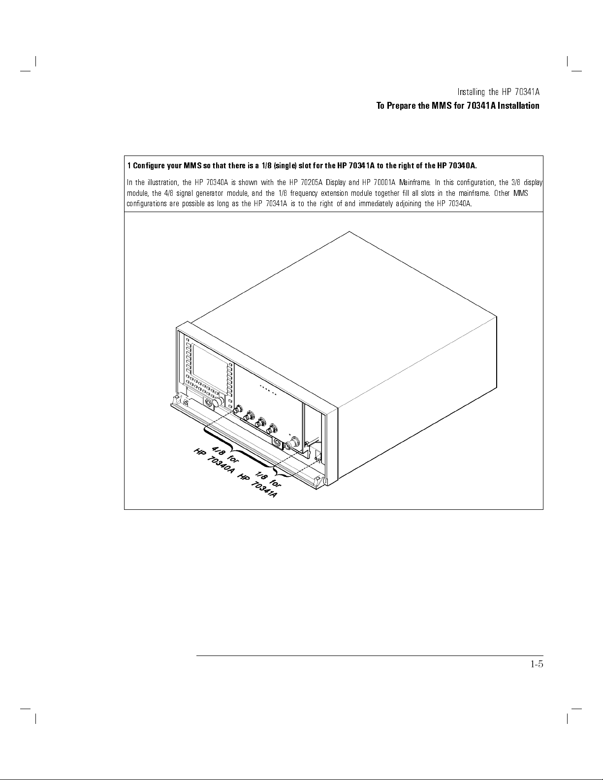
1 Congure your MMS so that there is a 1/8 (single) slot for the HP 70341A to the right of the HP 70340A.
In the illustration, the HP 70340A is shown with the HP 70205A Display and HP 70001A Mainframe. In this conguration, the 3/8 display
module, the 4/8 signal generator module, and the 1/8 frequency extension module together ll all slots in the mainframe. Other MMS
congurations are possible as long as the HP 70341A is to the right of and immediately adjoining the HP 70340A.
1-5
Page 18
Installing the HP 70341A
To Prepare the MMS for 70341A Installation
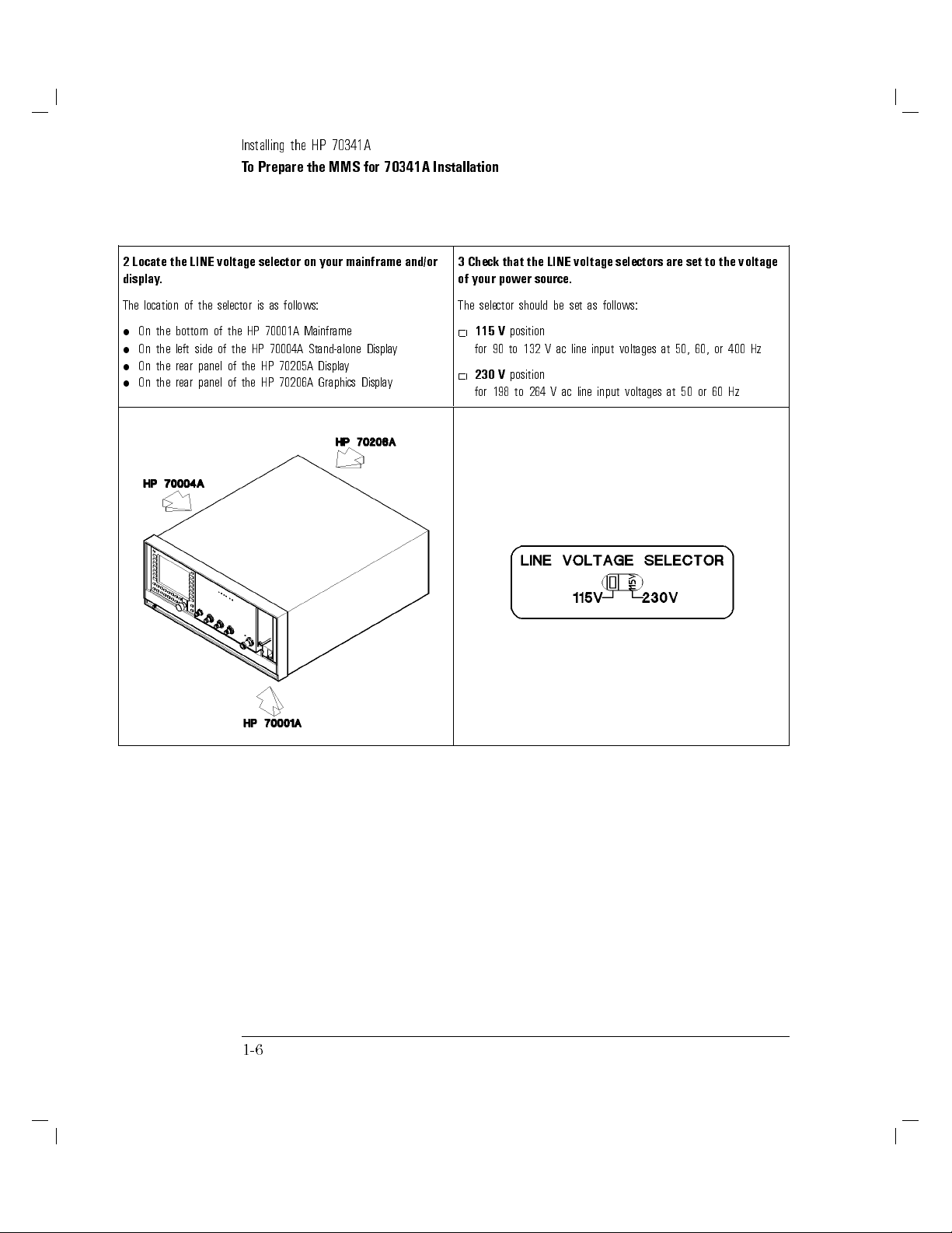
2 Locate the LINE voltage selector on your mainframe and/or
display.
The location of the selector is as follows:
On the bottom of the HP 70001A Mainframe
On the left side of the HP 70004A Stand-alone Display
On the rear panel of the HP 70205A Display
On the rear panel of the HP 70206A Graphics Display
3 Check that the LINE voltage selectors are set to the voltage
of your power source.
The selector should be set as follows:
115 V
position
for 90 to 132 V ac line input voltages at 50, 60, or 400 Hz
230 V
position
for 198 to 264 V ac line input voltages at 50 or 60 Hz
1-6
Page 19

Installing the HP 70341A
To Prepare the MMS for 70341A Installation
4 Locate the HP-MSIB switches on the rear panel of the
HP 70340A signal generator and check that they are set to the
correct address.
The factory preset HP-MSIB address for the HP
70340A is 0,29 (row 0, column 29) as in the example below.
Refer to step 2 of the procedure,\To Check and Set the HP 70341A
HP-MSIB Address" for help in determining the decimal address.
5 If any other modules are in your MMS, verify the HP-MSIB
address of each.
Refer to your module user's guide, or refer to the following
information when verifying addresses:
Each element (module) in the MMS must have a unique HP-MSIB
address.
There are 255 legal addresses which consist of a row and a
column address.
Address 0, 31 is an illegal address. No elements should be set to
this address.
,
capability
reporting
error
have
must
have
of
address
HP
the
Conguration
y
for
are
address of
and
be
slave
a
.
70341A
the
Stand-alone
0.
address
row
a
element
module
a
of
HP-MSIB
address switches
instrument
y
displa
system
the
of
must
refer
,
Address".
or
instruments
0.
equal
be
the
to
the
on
These
.
only
module
y
an
usually
(or
to
procedure
back
within
In
element
have
Slave
The
greater
change
o
T
Check
o
\T
Note
Graphics
the
switches
system.
the
order to
a
elements
column
that
do
access HP-IB
row
row
0
than)
HP-MSIB
the
Set
and
Displa
the
Displa
not
address
address.
cannot
address
its master
y
set the
the
of
6 Connect the power cable(s) to the system and then to the
power source.
WARNING
This is a safety Class 1 product (that is, it is provided with a
ground
earth
cable
must
safety
Whenever it
.
made
be
is
inoperative
likely
protective
be
must
ground
the
earth terminal).
through
provided
impaired, the
is
uninterruptible
An
power
the
product
7 Select the LINE (mains) switch to turn the mainframe and/or
display on, and check that no error indicators are on after the
power up test completes.
When you turn the MMS on, the power light comes on and the
ventilation
that
.
.)
mainframe
LEDs) to turn on and then o
are
fans
the
Note that the
fan(s) start.
on
In
(The
for
the
module
placing
y
b
addition, it
your
is
hand near
normal
during a power-up test.
ERR
LEDs should be o when the power-up test is
but,
quiet,
are
fans
complete.
you
back
LEDs
feel
can
the
of
(including
that
ERR
1-7
Page 20

To Check and Set the HP 70341A HP-MSIB
Address
This procedure explains how to locate and determine the module address
in case you want to change it. If you do change the HP-MSIB address,a
nonconductive stylus such as a toothpick is useful for setting the switches.
1-8
Page 21
Installing the HP 70341A
To Check and Set the HP 70341A HP-MSIB Address
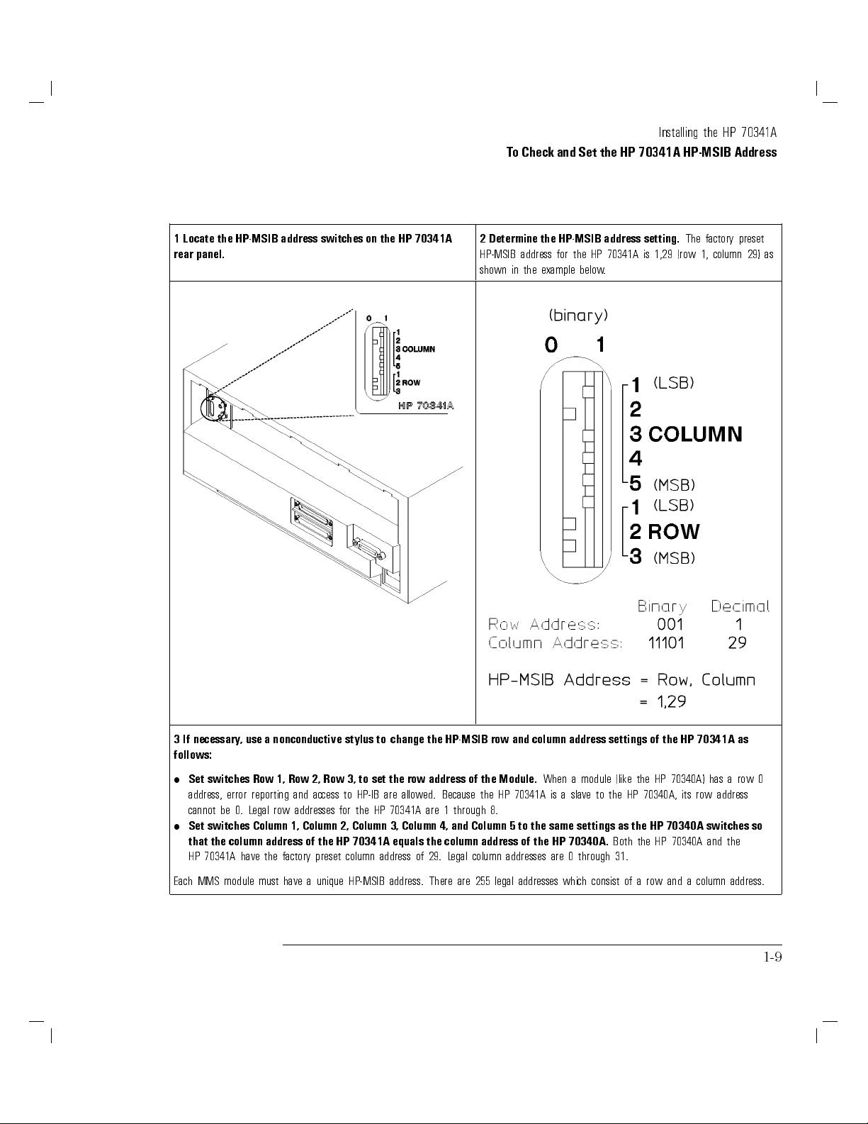
1 Locate the HP-MSIB address switches on the HP 70341A
rear panel.
2 Determine the HP-MSIB address setting.
The factory preset
HP-MSIB address for the HP 70341A is 1,29 (row 1, column 29) as
shown in the example below.
3 If necessary, use a nonconductive stylus to change the HP-MSIB row and column address settings of the HP 70341A as
follows:
has a
70340A)
HP
the
(like
module
a
70341A
When
is
address
70340A, its
HP
the
to
slave
a
Both the HP
row
70340A and the
of a row and a column address.
Module.
the
are
Because
through
1
of
HP
the
8.
switches
Set
error
address,
0.
be
cannot
Set switches Column
row address
the
set
to
3,
Row
2,
Row
1,
Row
reporting
egal
L
row
access
and
addresses
to
for
HP-IB are
the
allowed.
HP 70341A
1, Column 2, Column 3, Column 4, and Column 5 to the same settings as the HP 70340A switches so
that the column address of the HP 70341A equals the column address of the HP 70340A.
HP 70341A have the factory preset column address of 29. L
egal column addresses are 0 through 31.
Each MMS module must have a unique HP-MSIB address. There are 255 legal addresses which consist
row
0
1-9
Page 22

To Install the HP 70341A into the MMS
The following steps show you how to properly install the HP 70341A into
your mainframe. The procedure is simple; the only tool required is an 8 mm
hex-ball driver which is provided with your mainframe and/or display.
1-10
Page 23

Installing the HP 70341A
To Install the HP 70341A into the MMS
1 Before installing the HP 70341A into the mainframe or
display, turn the mainframe and/or display o by setting the
LINE (Mains) switches to the o position.
If the system is on when you install the module, personal injury or
damage to the instrument can occur. (On some MMS mainframe
models, the door will not open unless the LINE switch is o.)
3
the
Slide
right
the
of
70341A
HP
the HP
into
70340A.
adjoining
slot
(single)
1/8
a
and
2 Open the front panel mainframe or display door.
to
Using
4
the
close
an
front
mm
8
hex-ball
panel door
driver
.
tighten
,
the
hex
nut
latch,
and
1-11
Page 24
To Make Rear Panel Connections
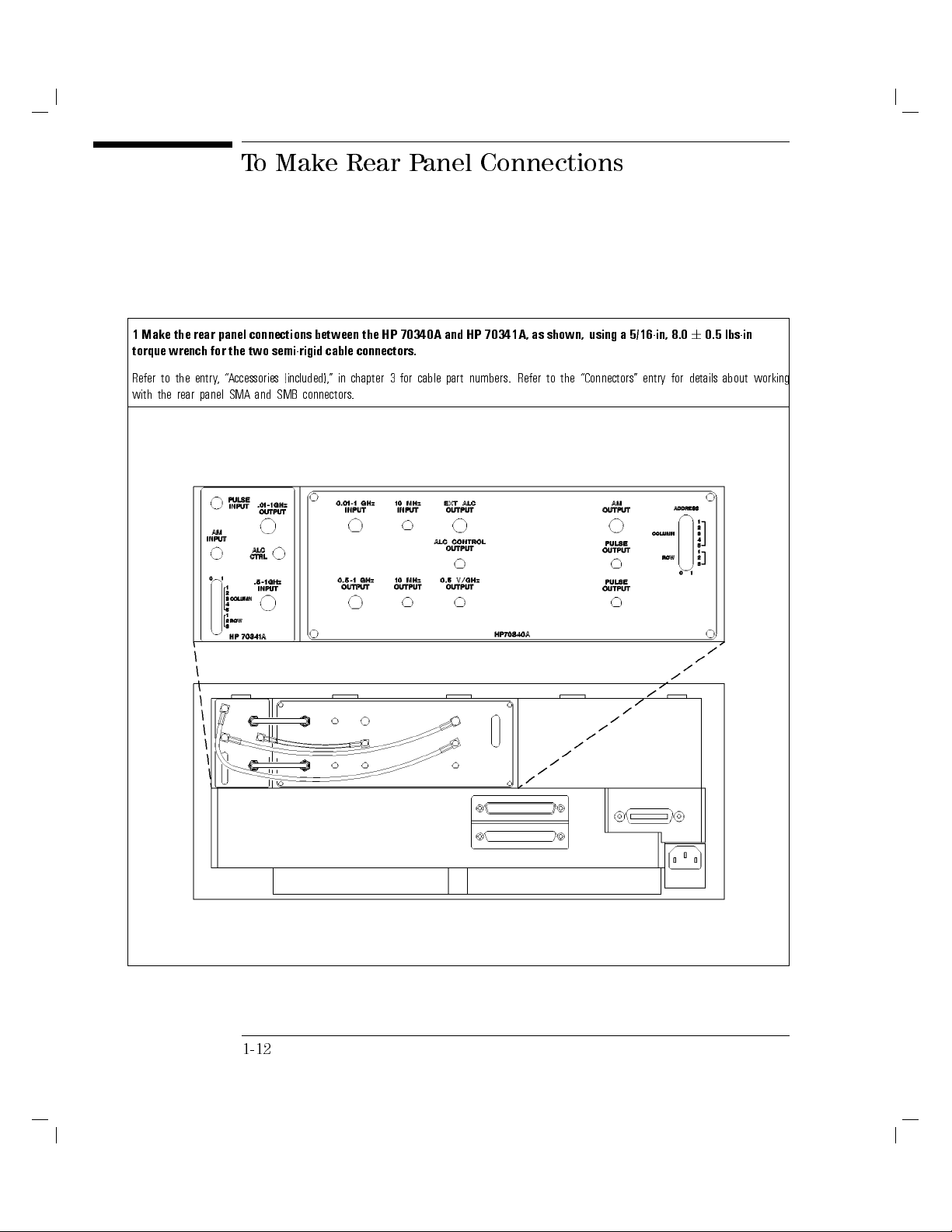
1 Make the rear panel connections between the HP 70340A and HP 70341A, as shown, using a 5/16-in, 8.060.5 lbs-in
torque wrench for the two semi-rigid cable connectors.
Refer to the entry, \Accessories (included)," in chapter 3 for cable part numbers. Refer to the \Connectors" entry for details about working
with the rear panel SMA and SMB connectors.
1-12
Page 25
ToPower-On the HP 70340A/41A System
This procedure veries that the HP 70340A and HP 70341A are properly
installed in the MMS by ensuring that the HP 70340A accepts a 500 MHz cw
frequency front panel input.
This procedure requires an MMS display for front panel instrument operation.
If you are not using a display, follow steps 1 through 3 of this procedure,and
then, refer to the \Generating Signals" chapter in the
Guide
for examples of HP-IB code for generating signals.
HP 70340A/41A User's
1-13
Page 26

Installing the HP 70341A
ToPower-On the HP 70340A/41A System
1 Set the mainframe LINE (Mains) switch to ON.
When you turn the MMS on, the power light comes on and the
ventilation fans start. (You can feel that the fans are on by placing
your hand near the back of the mainframe.) In addition, it is normal
for the HP 70340A and HP 70341A LEDs (including the
ERR
LEDs)
to turn on and o during a power-up test.
Note that the HP 70340A
complete, but, the HP 70341A
ERR
LED may remain on after the test is
ERR
LED should be o.
3 If the HP 70340A ERR LED remains on after turning the
the
clear
to
order
in
follows
as
queue
error
the
read
on,
system
queue.
4
1.
2.
Press
Press
The
HP
\
DISPLA
F
F
F
F
F
F
F
F
REPORT
y
displa
70340A,
5
Y
F
FF
FF
F
F
F
F
F
F
F
F
F
ERRORS
should show
Signal
.
F
F
F
F
F
F
F
F
F
F
F
F
F
F
F
.
message:
the
current
the
with
(along
"
Gen
HP-MSIB address.)
yed:
be displa
also
should
message
error
70340A
HP
The
power
at
lost
data
1803,
"RAM
on;(1803)"
70340A, Signal
HP
\
the
show
not
does
y
displa
the
If
3.
press
screen,
"
Gen
F
F
F
F
F
F
MORE
F
F
F
F
F
F
F
F
F
F
ERRORS
F
F
F
F
F
F
F
F
F
F
FF
FF
F
F
until
it does.
2 If the display does not show the HP 70340A menu, press the
following keys to call it up:
1.
4
DISPLAY
FFFFFFFFFFFFFFFFFFFFFFFFFFFFF
2.
NEXT INSTR
5
FFFFFFFFFFFFFFFFFFFFFFFFFFFFFFFFFFF
or
SELECT INSTR
until the display
shows:
HP 70340A Signal Generator
3.
4
Note that the
MENU
5
ACT
LEDs light when the HP 70340A and HP 70341A
are accessed through HP-MSIB for front panel operation.
4 Enter a signal generator cw frequency of 500 MHz by
keys/softkeys:
F
HP
and
the
y
b
turn
MHz
70340A/41A
to
verication.
display
70341A
signal
and the
on
the
generator
User's
70340A/41A
HP
are
displa
Guide
properly
as
message:
y
for
installed,
indicated
operational
Calibration
data
the
the
y
b
verication
Guide
fact
for
selecting
1.
2.
3.
If
should
that
the
FF
FF
FF
FF
F
F
F
F
F
F
F
F
FREQ
CW
455405405
FF
FF
F
F
F
F
F
F
MHz
70340A
HP
the
accepted
be
ERR
no
F
F
LEDs
500.000000
HP
the
to
Refer
instruments or
of the
performance
full
following
F
F
4.
4
Press
the
HP
MENU
70340A
5
front
to
order
in
menus.
panel
turn o
the ERR
LED and
return to
Note that, if you have just installed (or removed) the HP 70341A,
error message 1803 does not imply a true error in instrument
operation. Its purpose is to remind you that since the valid cw
frequency range has changed, the instrument presets to 3 GHz, and
consequently
fact,
In
correction
state. Refer to the
loses
level
settings, save/recall
panel
front
all
the
because
lost
is
data
registers,
instrument
HP 70340A/41A User's Guide
and
preset
the
goes to
\Display Menus and
shutdown.
power
to
prior
setting
y
frequenc
cw
the
Functions" INSTR PRESET entry for the entire instrument preset state
1-14
.
Page 27

2
Encounter
ou
Y
If
Problem
a
Page 28

If You Encounter a Problem
If you have a problem during installation of the HP 70341A, check the
following list of commonly encountered problems and troubleshooting
procedures. If the problem that you encounter is not in the following list,
refer to the Troubleshooting section of the
Manual
oce for service.
The procedures in this chapter do not require either internal access to the
instrument
procedures is
for your MMS mainframe, or contact the nearest Hewlett-Packard
equipment.
or
any
an 8
external
mm hex
test
ball driver
Installation and Verication
required
tool
only
The
.
for
these
2-2
Page 29

If the HP 70341A is mechanically damaged
upon receipt
1. Contact the nearest Hewlett-Packard oce and the carrier.
2. Keep the shipping materials for the carrier's inspection.
3. Refer to the procedure, \If you need to return the HP 70341A for repair."
2-3
Page 30

If a module appears dead
If any module or the mainframe appears to be dead after you turn the LINE
switch to the ON position, follow these steps.
If the power light on the mainframe does not light
connected.
is
Check
Check
V) for
230
LINE voltage
The
the
that
that the
the
power
LINE
power
cord
voltage
source
selector
selector
.
switch
located:
is
V
correct
the
to
set
is
voltage
(115
or
2-4
on the
on the
on
the
left-hand
bottom
panel
rear
of
side
the
of
70004A
HP
the
of
70001A
HP
HP
the
Voltage Selection Location
Line
mainframe
70206A
display
and HP
70205A
displays
Page 31

If You Encounter a Problem
If a module appears dead
Check that the mainframe fuse is good and the proper value.
The fuse is located inside of the power-cord receptacle housing on the rear
of the display or mainframe. Refer to the gure below. The metric 6.3A,
250V fuse is HP part number 2110-0703.
Replacement
Line
Fuse
Removal
and
You can use a continuity light or an ohmmeter to check the fuse.An
ohmmeter should read very close to zero ohms if the fuse is good. Visual
inspection of the fuse is not a sure check that the fuse is good.
attempt power-up
and
replace
bad,
is
fuse
the
If
continued
or
G
N
NI
R
A
W
F
that
the
is
protection against
type and
same
it
rating.
re
hazard,
.
replace
the
fuse
with
one
Remove the HP 70341A from the MMS and attempt to power-up the
mainframe, itself.
2-5
Page 32

If You Encounter a Problem
If a module appears dead
If the mainframe power light does not come on, the mainframe or another
module within the mainframe is bad. If the mainframe does power-up, the
fault lies with the HP 70341A.
If the module front panel LEDs do not light when the
MMS is turned on
Check
HP
Refer
regarding
Contact
the
If
fan
Set
your
that
to
the
and
display
70341A
proper
nearest
the
mainframe
does
the
not
mainframe
display
recycling
mainframe
or
operation.
Hewlett-P
power
start
LINE
mainframe
or
power
ackard
(Mains)
.
installation
oce
light
switch
working properly
is
manual
service
for
but
on,
is
.
OFF
to
by removing
information
for
.
ventilation
the
Check for blockage of the fan intakes at the bottom rear of the mainframe.
Refer to your MMS mainframe manual.
E
T
O
N
The HP 70004A Displa
y fan is very quiet.
the
2-6
Page 33

If the HP 70341A ERR LED remains on after
the power-up test is complete
Refer to the
HP 70341A Service Guide
, or contact your local
Hewlett-Packard oce for service.
2-7
Page 34

If the HP 70340A ERR LED or the display E
remains on after the power-up test is complete
Check the error queue for error messages.To check the error queue:
1.
Press
4
DISPLAY
2.
If necessary, press
5
and then
NNNNNNNNNNNNNNNNNNNNNNNNNNNNNNNNNNNNNNNNN
REPORT ERRORS
NNNNNNNNNNNNNNNNNNNNNNNNNNNNNNNN
NEXT INSTR
.
until the HP 70340A errors are
displayed.
3. Check the display for the reported error(s).
4. Press
5.
Check
4
MENU
ERR
the
If
\Error
Messages" chapter
assistance
that
5
to clear the queue and return to the HP 70340A screen.
is
LED
in correcting
ERR
the
still
LED
refer
on,
or your
the error(s).
or the
display
70340A/41A
HP
the
to
mainframe/display user's
ashing.
not
is
E
User's
Guide
guide for
error
any
If
HP-MSIB
the
over
than
more
If
module
a
,
faulty
Check
that
Mainframe
mainframe
Check for
Check that
indicator is
error
one
is
are
there
messages
error
operating
the
(secure)
HP-MSIB
proper
ashing, this
.
bus
indicator
faulty
no
and
is
HP-MSIB
the
or
,
mainframe
appear
will
service
HP-MSIB
cables
are
indicates
ashing,
error
on
manuals
cable
connected
that
mainframe
the
display
mainframe
a
if
are
.
cables
messages
the
connections
serially
module
the
probably
Refer
.
error
.
form
to
cannot
HP-MSIB
faulty.
your
to
occurs
loop
a
talk
is
.
.
Check that no two modules within the system have the same HP-MSIB
address.
In order to change a module HP-MSIB address, refer to the procedure,\To
Check and
Set
the
HP
70341A
HP-MSIB
ddress"
A
chapter
in
1.
2-8
Page 35

If either the display HP-MSIB or mainframe I/O
Check Indicator remains on
If either of these indicators is on, there is a problem with the HP-MSIB.
Verify that the power to all mainframes and stand-alone displays is on.
Check that the HP-MSIB cables are securely connected and connected in
serial to form a loop.
Check that no two modules within the system have the same HP-MSIB
address.
o
\T
all
,
of
the
on.
In order
to change
Check and
Check
for
HP-MSIB
indicator
the
If
.
faulty
indicator
the
If
cables
or
Set the
a faulty
cables
with
a module
HP-MSIB A
mainframe or
and noting
remains
light
turns
light
module(s)
the
HP-MSIB
ddress" in
stand-alone
whether or
the
on,
problem
the
o,
within
address
chapter
the
not
mainframe
is
system.
the
refer
,
1.
display
indicator
or
either
the
to
removing
by
display
with
procedure
remains
light
probably
is
HP-MSIB
the
2-9
Page 36

If the mainframe CURRENT indicator remains
on
This indicator turns on when the mainframe power supply senses an
overload.
Check to see which module is causing the current overloading condition
through the following steps:
1. Remove one module from the mainframe.
2. Cycle the power.
.
faulty
indicator
the
If
indicator remains
If the
module causing
the
o,
turns
on, continue
the indicator
removed
to light
module
to remove
is identied.
is
modules
until
the
indicator remains
the
If
mainframe
probably
is
on after
faulty
modules
all
are
removed,
the
.
2-10
Page 37

If the display does not accept the 500 MHz cw
frequency data input
Check that the HP 70341A HP-MSIB row address is greater than the HP
70340A row address.
Check that the HP 70341A HP-MSIB column address is equal to (or greater
than) the HP 70340A column address.
NNNNNNNNNNNNNNNNNNNNNNNNNNNNNNNNNNN
Use the
4
DISPLAY
5
key,the
address map
softkey, and the Knob in order to
view each module's HP-MSIB address using the front panel screen.
the
If
Correctly
1.
the
Refer
A
Cycle
2.
HP-MSIB
HP
to
ddress"
power
address switches
the HP-MSIB
reset
70341A.
procedure
the
help
for
.
\T
,
determining
in
are not
addresses so
Check
o
or
set correctly:
that the
Set
and
setting
the
the
HP 70340A
70341A
HP
HP-MSIB
can
HP-MSIB
addresses
address
.
2-11
Page 38

If you need to return the HP 70341A for repair
The following procedure describes how to prepare the module for shipment:
CAUTION
Instrument damage can result from using packaging materials other than
the original shipping materials or equivalent. Never use styrene pellets as
packaging materials. They do not adequately cushion the instrument or
prevent it from shifting in the carton. They cause instrument damage by
generating static electricity.
attach
Fill
1.
the
to
information
Type
1.
Description
2.
blue
a
out
instrument.
of
repair
with
service
of
card
blue
a
If
returned
the
required.
problem;
the
(located
repair
instrument:
state
at
card
if
end
the
not available
is
problem
the
of
this
manual)
,send
constant
is
and
the following
or
intermittent.
person.
data
recorded
for
2.
Name
3.
Return
4.
Model
5.
Full
6.
List
7.
Send
and
number
serial
any
of
copies
phone
address
number
accessories
any error
of
number
.
returned
of
of
instrument.
returned
of
returned
messages and
technical
instrument.
with
contact
instrument.
performance
instrument.
Error
comes
messages
the
from
are read
incoming
from the
inspection tests
70340A/41A Calibration Guide
MMS error
.
erformance
queue.
P
or performance
tests in
data
the
it
the
HP
2-12
Page 39

If You Encounter a Problem
If you need to return the HP 70341A for repair
No.
Materials
Description
Pad
Pad
70341A
HP
Item Qty HP
Packaging
Part
1 2 70100-80008 Foam
2 1 70100-80007 Corrugated
3 1 70100-80006 Carton
3. Pack the instrument in the original shipping materials or the equivalent.
can
.
be
Shipping
If
4.
materials
original shipping
the
can
repackaged for shipment using
rap the instrument in
1. W
ESD-caused damage
.
ordered
be
materials
are
from
not
Hewlett-P
any
available
ackard oce
instruments
,
the following instructions:
antistatic plastic to reduce the possibility of
2. For instruments that weigh less than 54 kg (120 lb), use a
double-walled,
corrugated cardboard carton of 159 kg (350 lb) test
2-13
Page 40

If You Encounter a Problem
If you need to return the HP 70341A for repair
strength. The carton must be large enough and strong enough to
accommodate the instrument. Allow at least 3 to 4 inches on all sides
of the instrument for packing material.
3. Surround the equipment with 3 to 4 inches of packing material to
protect the instrument and prevent it from moving in the carton. If
packing foam is not available, the best alternative is S.D.-240 Air Cap
TM
from Sealed Air Corporation (Commerce, California 90001). Air
Cap is a plastic sheet lled with 1-1/4 inch air bubbles. Use the pink
(antistatic) Air Cap to reduce static electricity.Wrap the instrument
several times in this material to protect the instrument and prevent it
from moving in the carton.
.
WITH
tape
CARE."
Seal
5.
Mark the
6.
Retain
7.
the
carton
carton
copies
of
with
\FRA
all
strong
GILE,
shipping
adhesive
nylon
HANDLE
papers
.
2-14
Page 41

3
Reference
Page 42

Reference
This chapter contains reference information that is useful for the Installation
procedures in this book. Instrument electrical specications for the
HP 70340A and HP 70341A combination are listed here as well as other
specications and options that apply specically to the HP 70340A.
For easy reference, all entries in this chapter are alphabetized.
3-2
Page 43

Accessories (included)
The HP 70341A Frequency Extension Module shipment includes the following:
(1)
HP 70341A Frequency Extension Module
(2)
2 Semi-rigid Cables (HP p/n 5021-9263)
(3)
Flexible Cable (HP p/n 08753-60061)
(4)
2 Flexible Cables (HP p/n 5061-1022)
.
now
reading,
are
you
which
you
,
below
vel Information
e
the HP 70341A. It is
will
receive:
also
y.
the
Guide
option(s)
The
(5)
options
(5)
Option 0B2-
Option 0BW-
Option 0BV-
Installation
70341A
HP
ordered
you
If
HP 70341A Installation Guide
HP 70341A Service Guide
HP 70341A Component-L
Note that a power cable is not shipped with
supplied with your MMS mainframe or stand-alone displa
3-3
Page 44

Accessories (not included)
Several accessories (such as cables) which are not included with the
Frequency Extension Module may be required for certain applications.
A list of useful cables and other accessories follows:
Accessories (not included)
Accessory Part Number
meter
5
HP-MSIB
HP-MSIB
HP-MSIB
HP-MSIB
HP-MSIB
Cable-
Cable-
Cable-
Cable-
Cable-
1.0
2.0
6.0
30
meter
meter
meter
meter
HP
HP
HP
HP
HP
70800A
70800B
70800C
70800D
70800E
3-4
SMB
SMB
SMA
SMA
push-on
coax
ex
coax
ex
Cable-
Cable
Cable
(rear
cm
30
(inter-module
(mainframe
connections)
panel
connections)
connections)
08753-60061
5061-1022
5061-9038
5061-9039
connections)
panel
(rear
cm
15
Cable-
push-on
SMB(f) to BNC(m) Cable 85680-60093
SMA(f) to SMA(m) Cable 8120-1578
8
8710-1307
removal/installation)
(module
Driver
ball
hex
mm
Fuse- 6.3 A (for replacement in mainframe) 2110-0703
Page 45

Reference
Accessories (not included)
For cabinet interconnect and rack mounting kits, refer to your mainframe or
display installation manuals.
For documentation pertaining to the HP 70340A and the HP 70341A, refer to
the Learning Products Map at the end of this book.
3-5
Page 46

Connect
o
T
Cables:
Semi-rigid
Connectors
The HP 70341A rear panel has both threaded SMA and unthreaded SMB
connectors.
SMA Connectors
used
semi-rigid
Two
microwave
carry
to
Because
parts
minor mechanical
can produce
connectors
Ensure
1.
Ensure
2.
outer
metal
coaxial
signal
performance
be treated
center
the
insulating
the
conductor is
particles.
cables
with
between
imperfections
degradation,
care
the
with
conductor
material
undamaged,
SMA
the
aorded
not
is
between
clean,
(3.5
HP
in
bent
mm)
70340A
these
is
it
any
or
the
free
and
connectors
and
cables
important
microwave
damaged.
center
contamination
of
are
70341A
HP
the
their
and
the
component:
conductor
connecting
cables
the
and
from
.
and
CAUTION
If necessary
3.
with
alcohol.
clean
,
the
cable
ends
using
cotton
a
swab
lightly
moistened
4. Inspect the mating connectors and clean them if necessary.
5. Allow the alcohol to evaporate completely before assembling the
connectors.
6. Retract the outer nuts away from the ends of the cable.
Carefully
7.
mating
insert
connectors
.
partially
cable
the
of
ends
both
Do not force the cable when mating connectors
shells of
the
into
. Minimal force is required
the
to seat the center pin in the mating socket. If excessive force is used, the
microwave device to which the cable is connected can be damaged.
3-6
Page 47

Reference
Connectors
8. Be sure the center pin of the cable is aligned with the socket of the
mating connector, then gently push the cable into place.For short cables,
insert both center pins simultaneously.
CAUTION
Disconnect
o
T
Cables:
Semi-rigid
Do not cross-thread the nut of the semi-rigid cable on the shell of the mating
connector. Do not over-tighten the nut. Either of these actions can result in
damage to the microwave device to which the cable is connected.
9. Ensure the cable is seated in the mating connector at both ends, then
slide the nuts along the cable to the mating connectors.
10. Start the nut on the mating connector with your ngers. If resistance is
felt,
Tighten
11.
12. Using
of 8.0
Disconnect
1.
loosening
connector
remove
When
2.
semi-rigid
sockets
Place
3.
the
back
both
a 5/16-inch
lbs-in.
6
1.0
3.5
5/16-inch
the
Loosen
.
either
nuts
both
cable
.
protective
away
nut
connector
torque
(SMA)
mm
the
end.
completely
are
gently
on
caps
from
nuts
wrench,
connectors
until
nut
at
nuts
the
until
semi-rigid
connector
the
nger-tight.
tighten
from
completely
is
it
ends of
both
of the
free
center
cable
and
connector
each
mating
the
free
cable
the
mating connectors
disengage from
pins
connectors
,
nut
connector
the
of
before
store
and
value
a
to
by
mating
attempting
the
pull
,
the mating
cables
to
to
again.
begin
prevent damage to the center pins or accidental bending.
SMB
Three exible coaxial cables with
Connectors
SMB (push-on) connectors carry signals
between the HP 70340A and the HP
70341A.
3-7
Page 48

Reference
Connectors
To Disconnect Flexible
Coaxial Cables:
CAUTION
1. Grasp the connector body and pull steadily until the connector separates
from its mate. If the connectors will not separate easily, rock the connector
body
very
slightly side-to-side while exerting a steady pull.
2. If the connectors still will not separate, place the jaws of a pair of
long-nose pliers under the connector body. Use the jaws as a fulcrum to
lift the connector away from the rear panel. Use a piece of tape or other
material under the pliers to avoid scratching the surface to which the
connector is mounted.
Exert force only on the body of the connector. Do not pull on the cable.
These connectors are easily damaged.
3-8
Page 49

Electrostatic Discharge Information
Electrostatic discharge (ESD) can damage or destroy electronic components.
Therefore, all work performed on assemblies consisting of electronic
components should be done at a static-safe workstation.
The following gure shows an example of a static-safe workstation using
two types of ESD protection: 1) conductive table mat and wrist strap
combination, and 2) conductive oor mat and heel strap combination. These
methods may be used together or separately. (A list of static-safe accessories
.)
and
their
part
numbers
is
given
on
the
following
pages
Static-Safe Workstation
3-9
Page 50

Reference
Electrostatic Discharge Information
Reducing Damage Caused By ESD
Below are suggestions that may help reduce ESD damage that occurs during
testing and servicing instruments.
PC Board Assemblies and
Electronic Components
CAUTION
Equipment
est
T
Handle these items at a static-safe workstation.
Store or transport these items in static-shielding containers.
Do not use erasers to clean the edge connector contacts. Erasers generate
electricity
static
electrical
not
Do
particles
lint
or
quality
use
paper
and
of
left
the
of
on
remove
contacts
kind
any
the
the
.
to
contact
thin
clean
surface
gold
the
plating,
connector
edge
cause
can
which
degrades
contacts
intermittent
the
aper
P
.
electrical
connections.
Do not
touch
Always handle
assembly
board
PC
lint-free
20%
cloth
deionized
the
board
with
water
edge
assemblies
edge
solution
a
.
connector
connector
procedure
This
of
80%
the
or
edges
contacts
by
contacts
electronics-grade
should
trace
.
may
performed
be
surfaces
cleaned
be
with
by using
isopropyl
a
at
a
alcohol and
static-safe
hands
bare
workstation.
Before
time
connecting
day
each
coaxial
any
momentarily
,
cable
ground
to
the
an
instrument
center
and
connector for
conductors
outer
the rst
the
of
cable.
Personnel should be grounded with a resistor-isolated wrist strap before
touching the center pin of any connector and before removing any assembly
from the instrument.
.
sure
Be
of static
3-10
that
charge
instruments
all
.
are properly
earth-grounded
prevent
to
buildup
Page 51

Reference
Electrostatic Discharge Information
Static-Safe Accessories
The following is a list of static-safe accessories that may be obtained from any
Hewlett-Packard oce by using the HP part numbers listed.
HP Part Number 9300-0797
Includes: 3M static control mat .6m x 1.2m (2 ft. x 4 ft.)
4.6m (15 ft.) ground wire
wrist strap and attachment cord
art Number
HP P
Wrist
art
P
HP
rist
W
art
P
HP
rist
W
art
P
HP
ESD
art
P
HP
Shoe
strap cord
Number
(large)
strap
Number
(small)
strap
Number
strap
heel
Number
ground
9300-0980
1.5m (5
9300-0985
9300-0986
9300-1169
(reusable
9300-0793
(one-time
strap
ft.)
6
to
12
use
months)
only)
3-11
Page 52

Options
The following paragraphs explain the dierent warranty and documentation
options available for the Frequency Extension Module.
Warranty Options
Option
Additional
Service
Option
Return
Service
Option
Mil-std
-
W30
Return
-
W32
Calibration
HP
to
-
W34
Calibration
wo
T
Three
Three
ears
Y
HP
to
Y
Y
Service
ears
ear
Consult
Consult
Consult
Longer
HP sales
your
your
your
your
term
representative
sales
HP
representative
sales
HP
representative
sales
HP
warranty
and
representative
calibration
details
for
details
for
details
for
details
for
services
.
on this
on
on
available
are
this
this
option.
option.
option.
Please
.
consult
3-12
Page 53

0B2
Option
Documentation
0BW
Option
Assembly-level
Documentation
-
-
Extra
Add
Service
Documentation Options
The documentation options: 0B2, 0BW,and0BV that follow are available
when the Frequency Extension Module is ordered and are received with the
shipment of the module. If the documentation is not ordered with the original
shipment but is desired at a later date, it can be ordered from the nearest
Hewlett-Packard oce using the book titles included in each of the following
paragraphs.
of
copy
extra
If
User
HP
If
documentation.
HP
the
Extension
option
0B2
70341A
option
0B
70340A/41A
calibration
Module
ordered,
is
Installation
ordered,
is
W
This
Calibration
service
and
option
if
shipment
the
Guide
the
includes
Guide
documentation
0B
.
shipment
HP
the
and
,
not
is
W
includes
contains
70341A
the
ordered.
an
a
Service
Calibration
shipped
not
is
of service
set
Guide
the
,
Software
the
with
Reference
Options
the
Note
.
Frequency
that
-
0BV
Option
Component-level
Documentation
Add
Service
option
If
Signal
shipped
is
V
0B
Generator
the
with
ordered,
the
Component-level
Frequency
Extension
shipment
Information
contains
Module
the
.
if
Note
70341A Modular
HP
that
option
0B
the
V
is
CLIM
not
not
is
ordered.
3-13
Page 54

Specications- HP 70340A/41A
This section contains the specications, supplemental characteristics, and
electrical options for both the HP 70340A and the HP 70340A/41A . Refer
to the
HP 70340A/41A User's Guide
for mechanical, documentation, and
warranty options for the HP 70340A. Refer to the \Options" entry in this
chapter for mechanical, documentation, and warranty options for the
HP 70341A.
the
Specications describe
55temperature range
indicated by
instrument
warranted,
italics,
capability
performance
are
instruments
the
unless otherwise
intended
your
in
to
application
.
warranted
noted.
provide
by
performance
Supplemental
information
describing typical,
over
characteristics
useful
in
but not
estimating
0
to
,
Frequency
1.0
Range:
HP
HP
HP
70341A
70341A
Resolution:
70340A
Modular
Frequency
only
can
(1
kHz
1
Extension
used
be
with
Hz
Signal
Generator
Module
combination
in
Option
1E8)
,
MHz
10
,
with
Stability (with external high stability timebase):
Aging Rate:
same as external reference.
Temperature Eects: same as external reference.
stability
10
2
high
-8
/day after
10
2
5
<
-6
<
Stability
(without
R
Aging
emperature Eects:
T
ate:
external
1.0
<
Frequency Switching Time:
<
100 ms to within 1 kHz, 10 MHz - 1 GHz.
over
50 ms to within 1 kHz, 1 - 20 GHz.
timebase):
72-hours
55
0to
3-14
20.0
to
GHz
1
to
HP
the
25
at
C
6
referenced to
C,
GHz
70340A.
10
C
25
C
Page 55

RF Output
Maximum Leveled Output Power:
Frequency Standard with Option 1E1
0.0101GHz +13 dBm +13 dBm
1018 GHz +11 dBm +10 dBm
18020 GHz +10 dBm +8 dBm
Reference
Specications- HP 70340A/41A
ypical
T
maximum
available
output
power
(Option
from
1
1E1)
20 GHz,
to
installed.
at 25
C
with
output
step
attenuator
3-15
Page 56

Reference
Specications- HP 70340A/41A
maximum
Typical
Display
Resolution:
0.01
available
dB
output
power
from
0.01
to
C.
25
at
GHz
1
Minimum
Minimum
ccuracy:
A
MHz
10
MHz
50
ccuracy:
A
Leveled
Leveled
dBm
4
0
(
MHz:
50
to
GHz
20
to
(over
Output
Output
to
6
specied
all
P
P
specied
dB
1.3
6
dB
1.0
(without
ower
(with
ower
maximum
temperatures
Option
Option
leveled
and
1E1):
1E1):
output
power
90
0
power)
levels)
dBm
dBm
4
0
10 MHz to 50 MHz:62.3 dB
50 MHz to 20 GHz:62.0 dB
The use of Type-N RF connectors above 18.0 GHz degrades specication
typically by 0.2 dB.
18.0 GHz
Flatness:
degrades
Level Switching Time:
6
specication
typically
<
15 ms (without step attenuator range change
by
Type-N
of
use
The
.
dB
0.5
Attenuator range changes occur at
<
Output SWR:
2.0 : 1 nominal
RF
dB
0.2
0
4dBm,
connectors
.
0
14 dBm,
above
0
24
dBm, etc
.
.)
3-16
Page 57

ypical output
T
level
accuracy
and
atness
Specications- HP 70340A/41A
dBm
85
0
and
+10
at
Reference
Spectral
Phase
SSB
Purity
Noise
(dBc/Hz):
Osets
Carrier Freq. 100 Hz 1 kHz 10 kHz 100 kHz
500 MHz
GHz
2
GHz
10
GHz
18
0
70
0
86
0
103
0
119
107
0
74
0
66
0
0
75
0
69
0
0
70
0
63
0
0
91
101
0
79
0
73
99
Phase noise decreases 6 dB/octave below 500 MHz and reaches a oor of
140 dBc/Hz.
<
0
3-17
Page 58

Reference
Specications- HP 70340A/41A
noise
<
than
55
0
phase
100
dBc
Hz
at
ypical single-sideband
T
Harmonics:
MHz,
50
at
require use
of external
output levels
GHz
1
<
+6
GHz,
20
and
high stability
0.01
dBm,
25
,CW
C
timebase.
to
20
mode.
GHz
Osets
less
Typical 2nd harmonic levels measured at output power of +6 dBm
Non-Harmonic Spurious (3 kHz):<0
frequency
synthesis
Non-Harmonic
Sub-Harmonics:
spurious).
Spurious
None
3 kHz):
<
(
<
3-18
60 dBc (includes power supply and
dBc
50
0
Page 59

Residual FM:
ypical
T
residual
FM
measured
Reference
Specications- HP 70340A/41A
mode.
bandwidth,
kHz
15
Hz -
50
in
CW
1
At
esidual
R
Noise
AM
150
0
<
140
0
<
GHz,
FM
dBm/Hz,
dBm/Hz,
15
<
decreases
Floor:
Hz
in
(at
1
0.01
kHz bandwidth.
15
-
Hz
50
GHz.
1
octave
per
dB
6
osets
and
dBm
0
GHz.
20
-
GHz.
1
-
below
greater
than
MHz from
5
carrier)
3-19
Page 60

Reference
Specications- HP 70340A/41A
Modulation
CARRIER FREQUENCY<25 MHz 25 -<64 MHz 64 -<128 MHz 128 -<500 MHz 500 -<1000 MHz 1 - 20 GHz
Minimum Pulse Width
<1
s
<
100 ns
<
25 ns
Typically<10 ns
Rise/Fall Time
Video Feedthrough
<
500 ns
<
350 ns
<
50 ns
<
2 mV peak-to-peak at 0 dBm
<
35 ns
<
20 ns
<
10 ns
<
20 mV peak-to-
peak at 0 dBm
Pulse Width Compression
out
(Video
y
Dela
Pulse
out)
RF
to
6
Pulse
150 ns
s
1
<
Modulation
On/O
Ratio:
6
15 ns
ns
200
<
dB
80
>
<
125
6
5ns
ns
100
<
ns
+8
at
ypical
T
Maximum Pulse R
modulation on/o
pulse
epetition Frequency:
ratio
>
3MHz
Minimum Pulse Duty Cycle: No restrictions on duty cycle
6
Pulse Level A
ccuracy (relative to CW):
Pulse Overshoot:
<
10%
1.0 dB
Input Impedance: 50 nominal; TTL drive levels
3-20
dBm
.
Page 61

Specications- HP 70340A/41A
Maximum Leveled Output Power in Pulse Mode (relative to CW):
0
0.5 dB
Reference
times, excellent
fall
and
rise
fast
delity
1E2)
and
3
(PRI):
419
the
HP
the
of
triggered
gated
to
Hz
ns
300
ms
,
mode
70340A
require
3
>
to
T
d
with
MHz
419
):
419
6
,
delay
external
ms
ms
doublet
from
pulse
ypical
T
Internal
Pulse
Triggered
Pulse
Pulse
Pulse
ariable
V
modulation
Source
Pulse
Source
with
Repetition
Repetition
Width
Pulse
envelope
(Option
Modes:
delay
Frequency:
Interval
(T
):
w
Delay
illustrates
pulse
Free-run,
doublet
,
ns
25
(free-run
to
video modulation
Variable Pulse Delay (triggered with delay & doublet modes,Td):
225 ns to 419 ms with625 ns jitter
Pulse Width/Delay/PRI Resolution:
Pulse Delay
pulse
All
during
modulation
use
(Video to RF,T
internal
of
specications
source
pulse
):
m
25 ns
Nominally
supplemental
and
.
,<20 ns, 1 to 20 GHz
characteristics
and
trigger
sync
atness
gated.
source
pulse
apply
and
.
to
3-21
Page 62

Reference
Specications- HP 70340A/41A
Frequency
Rates:
Modulation
to 1
1kHz
MHz
Flatness:62dB
CARRIER FREQUENCY 256 -<500 MHz 500 MHz -<1 GHz 1-2GHz 2 - 20 GHz
Maximum Deviation
Modulation Index
CARRIER
FM
FREQUENC
Sensitivity
FM Sensitivity Accurac
Incidental AM
1
10
MHz
16
-
kHz/V
40
Y
y
1.25 MHz peak 2.5 MHz peak 5 MHz peak 10 MHz peak
>
16
37
MHz
64
-
kHz/V
80
MHz
64
320
6
25% at 100
<
>
75
256 MHz
-
kHz/V
5%
kHz.
256
MHz
1.25
>
150
kHz/V
1 GHz
-
>
300
GHz
20
-
1
MHz/V
5
FM Input Impedence 600 nominal
Harmonic Distortion
1
Maximum deviation decreases by a factor of 2 for each octave below 256 MHz
<
1% (1 MHz peak de
viation @ 100 kHz rate)
3-22
Page 63

Specications- HP 70340A/41A
Logarithmic Amplitude Modulation (Scan Modulation)
Maximum Depth:>60 dB
Sensitivity: |10 dB/V; (0 to +6V for 0 to |60 dBc)
Step Response (50 dB change in level):
<
1GHz 1 - 20 GHz
rise time
fall time
<10
<20
s
s
<5
<5
Input Impedance: 5000 nominal
Mode
AM
Log
in
ower
Maximum
Leveled
Output
P
s
s
(relative
to
Reference
CW):
GHz
<
1
1-
GHz
4
GHz
>
4
+0 dB |4.5 dB |1.0 dB
Typical log AM error (deviation from desired depth) at 25C for carrier frequencies between 1.0
and 20 GHz
3-23
Page 64

Reference
Specications- HP 70340A/41A
Simultaneous Modulations
Full AM bandwidth and depth is available at any pulse rate or width. FM is
completely independent of AM and pulse modulation.
General
Programming
70340A
HP
The
Commands
complies
available
.
with
and
Programmable
for
IEEE
Please
consult
488.2-1987.
your
70341A
HP
Environmental
CS02,
Range:
EN
RS03.
Operating
Meets
EMC:
RE02,
2
art
P
Physical
Net Weight:
emperature
T
exceeds
or
CE03,
Dimensions
HP 70340A,<9 kg (20 lb).
HP 70341A,<2.5 kg (5 lbs).
Shipping:
HP 70340A,<15 kg (30 lb)
HP 70341A,<6 kg (12 lbs).
MMS
70340A,
HP
Size:
H
mm
148.5
70341A,
HP
148 mm H
2
Power Consumption:
HP 70341A,
4/8
mm W
192.8
2
MMS
1/8
48.2 mm W
<
30 Watts.
module
2
HP 70340A,<80 W
fully
are
Instruments
Optional
representative
sales
HP
0
55
to
55011/CISPR
module width.
mm
477.5
2
width.
477.5 mm D
.
compatible
(SCPI).
programming
CIIL
C
11/1990,
.
D
atts.
with the
programming
SCPI
for
Class
Standard
compatibility
details
and
A
is
.
Mil-Std-461C
3-24
Page 65

Reference
Specications- HP 70340A/41A
HP
HP
70340A
70341A
Dimensions
Dimensions
3-25
Page 66

Reference
Specications- HP 70340A/41A
Rear Panel Connectors
HP 70340A
0.5-1 GHz OUTPUT:
SMA connector outputs a 0.5 to 1.0 GHz signal for driving the HP 70341A
Frequency Extension module. The HP 70341A combined with the HP 70340A
extends the Signal Generator RF Output frequency range down to 0.01 GHz.
0.01-1 GHz INPUT:
SMA connecotr accepts the HP 70341A 0.01-1 GHz output signal. The HP
70341A signal
1.0 GHz
output available
is output
step
at the
attenuated
panel
front
in
the
RF
70340A
HP
Output
with
connector
of
the
HP
to
0.01
the
70340A.
INPUT:
MHz
10
connector
SMB
signal
for
impedance
accepts
operation
50.
is
from
a
MHz
10
external
an
external
to +10
Hz, 0
100
6
stability
high
dBm,
timebase
.
reference
Nominal input
OUTPUT:
MHz
10
the
.
nominally
panel
front
EXT
connector
SMB
use
for
dBm,
+3
EXTERNAL
connector
SMB
input connector)
ALC
CONTROL OUTPUT:
ALC
ALC
outputs
an
as
OUTPUT:
outputs
MHz
10
the
external
external
to the
reference
ALC
frequency extension
external
signal.
drive
reference
signal
module
signal,
(from
SMB connector supplies a010 to +10 V signal as a reference for leveling the
.01 to 1.0 GHz output signal of the HP 70341A.
0.5V/GHz OUTPUT:
SMB connector supplies a voltage proportional to output frequency for use
.
including the
with
AM
mm-wave
OUTPUT:
frequency
multipliers
SMB connector outputs AM drive signals (from
,
the front panel EXT PULSE
input connector) to the frequency extension module
HP
.
835XX
Series
PULSE OUTPUT:
2 SMB connectors
EXT PULSE input connector) to
output pulse modulation drive signals (from the front panel
the frequency extension modules
.
3-26
Page 67

Reference
Specications- HP 70340A/41A
HP 70341A
0.5-1 GHz INPUT:
SMA connector accepts a 0.5 to 1.0 GHz signal from the HP 70340A that
drives the HP 70341A Frequency Extension module.
0.01-1 GHz OUTPUT:
SMA connector outputs a 0.01-1 GHz signal which extends the HP 70340A
frequency range down to 0.01 GHz. The HP 70341A signal is output step
attenuated in the HP 70340A with the 0.01 to 1.0 GHz output available at the
front panel RF Output connector of the HP 70340A.
ALC CTRL:
panel
the
AM
connector
SMB
1.0
to
.01
INPUT:
AM
connector
SMB
OUTPUT
accepts
output
GHz
accepts
connector
.
0
a
signal.
AM
10
drive
to
+10
signals
V
signal
from
as
the
reference
a
70340A
HP
for
rear
leveling
PULSE
SMB
rear
INPUT:
connector
PULSE
panel
accepts
OUTPUT
pulse
connector).
modulation
drive
signal
from the
HP
70340A
Options
There are several electrical, mechanical, warranty, and documentation
options available for the HP 70340A.
Electrical Options:
There are three electrical options available for the Signal
Generator. These options are as follows:
Attenuator
dd Output
A
-
option
1E1
ordered, an
is
1E1
connector. The
. The correct amount
Option
If
RF OUTPUT
10 dB steps
the Signal Generator dependent on the output power
option
is installed, you can select whether or not the step attenuator will
Step
included
internal
step
attenuator
is
step attenuator has a range of 0 to 90 dB in
of attenuation is selected automatically by
level selected. If this
before
the
3-27
Page 68

Reference
Specications- HP 70340A/41A
automatically switch. This function is useful during certain applications,
such as when external automatic level control is used.
Option 1E2 - Internal Pulse Modulation Generator
If Option 1E2 is installed, the instrument includes as internal pulse source
with four dierent pulse modes. With Option 1E2, the six pulse modulation
modes available are: external, inverted external, free-run internal, gated,
triggered with delay, and pulse doublet. Pulse rise and fall times are
typically<5ns, minimum leveled pulse width is<25 ns, and on/o ration
is>80 dB.
Option 1E8 - 1 Hz Frequency Resolution
retrot
Consult
your
HP
representative
sales
for
details
availability
on
and
information.
Option
option
If
precision
-
1E9
1E9
connector
mm
3.5
ordered,
is
in
RF
place
Output
RF
the
of
Connector
OUTPUT
standard
the
connector
female
a
is
type-N
APC-3.5
male
connector
.
3-28
Page 69

4
Legal
Information
and
Regulatory
Page 70

Legal and Regulatory Information
This chapter contains information pertaining to safety, SCPI conformance,and
the warranty.
4-2
Page 71

Safety Considerations
This product and related documentation must be reviewed for familiarization
with safety markings and instructions before operation.
This product is a Safety Class I system (provided with a protective earth
terminal).
ower
Before
erify that
V
correct
fuses are
Applying
product
the
installed.
P
the
voltage
available
match
to
set
is
the
line
and
Safety Earth
uninterruptible
An
power
source
to
power cable set.
Ground
safety
product input
the
earth
ground must
wiring terminals
be provided
, power
from the
cable,
main
supplied
or
4-3
Page 72

Legal and Regulatory Information
Safety Considerations
WARNING
Any interruption of the protective (grounding) conductor (inside or
outside the system) or disconnecting the protective earth terminal will
cause a potential shock hazard that could result in personal injury.
(Grounding one conductor of a two conductor outlet is not sucient
protection.) In addition, verify that a common ground exists between the
unit under test and the system prior to energizing either unit.
Whenever it is likely that the protection has been impaired, the system
must be made inoperative and be secured against any unintended
operation.
If this system is to be energized via an autotransformer (for voltage
power
removed.
charged
be
line
example
(for
neutral (that
o
.T
unless
supplied
Energy
.
injury
even
.
only
fuses
,
short
if
reduction)
the
,
is
Servicing
avoid
qualied
djustments
A
the
to
available
make
grounded
instructions
dangerous
do
to
described
system's
many
at
so
Capacitors inside
the system
continued protection
For
with 250
normal
circuited
has been
V fuses
blow
fuse
time
,
holders
the
sure
of the
side
are
electric
shock,
.
in
instruments
points
the
may
system's
disconnected
against
delay
same
etc.).
,
of the
.
common
terminal is
mains supply
by
use
for
do
manual
the
protective
while
contacted,
if
,
instruments
from
re
current
Do not
connected to
.)
service-trained
perform
not
performed
are
covers
result
might
source
its
hazard,
rating
replace
and
use repaired
personnel only
servicing
any
with
are
personal
in
still
supply
of
the
type
fuses or
Safety
L
M
4-4
Symbols
Instruction manual symbol: The product will be marked with
symbol when it is necessary for the user to refer to
manual (see T
Indicates hazardous voltages
able of Contents for page references).
.
the instruction
this
Page 73

K
Legal and Regulatory Information
Safety Considerations
Indicates earth (ground) terminal.
WARNING
CAUTION
The WARNING sign denotes a hazard. It calls attention to a procedure,
practice, or the like which, if not correctly performed or adhered to,
could result in personal injury. Do not proceed beyond a WARNING sign
until the indicated conditions are fully understood and met.
The CAUTION sign denotes a hazard. It calls attention to a procedure,
practice, or the like which, if not correctly performed or adhered to, could
result in damage to or destruction of part or all of the product. Do not
proceed beyond a CAUTION sign until the indicated conditions are fully
understood and
met.
4-5
Page 74

SCPI Conformance
The HP 70341A is a slave module to the HP 70340A and, therefore, can only
be addressed via HP-IB through the HP 70340A. The Signal Generator uses
the SCPI (Standard Commands for Programmable Instruments) language
for HP-IB communication. The SCPI commands and queries that the Signal
Generator understands are listed and described individually in Chapter 7,
\Programming Commands" of the
HP 70340A/41A User's Guide.
The table in Chapter 10 of the
the
commands
they are
SCPI approved,
queries that
always
are
need more
you
If
part
(HP
SCPI
queries
and
are labeled
non-SCPI.
number
that
SCPI conrmed,
\IEEE 488.2
information about
H2325-90001).
HP 70340A/41A User's Guide
Generator
Signal
Required" and
SCPI,
or non-SCPI.
refer
understands
The
\IEEE
Beginner's
the
to
488.2
lists all of the
whether
and
commands
Optional"
Guide
and
to
4-6
Page 75

Warranty
CERTIFICATION
Hewlett-Packard Company certies that this product met its published
specications at the time of shipment from the factory. Hewlett-Packard
further
States
allowed
other
of
certies
National
by
Institute
Institute's
the
International
that
calibration
its
of
calibration
Standards
measurements are
Standards
Organization
echnology, (NIST),
and T
facility,
and
members.
traceable to
calibration facilities
to the
the United
to the
extent
4-7
Page 76

WARRANTY
This Hewlett-Packard instrument product is warranted against defects in
material and workmanship for a period of one year from date of shipment.
During the warranty period, Hewlett-Packard Company will, at its option,
either repair or replace products which prove to be defective.
For warranty service or repair, this product must be returned to a service
facility designated by HP. Buyer shall prepay shipping charges to HP and HP
shall pay shipping charges to return the product to Buyer. However, Buyer
HP
use
with
free
of
to
the
.
shall pay
all shipping
from another
warrants
HP
instrument
an
installed
on
instrument,
country.
that its
will execute
instrument.
that
software
or
charges,
duties
software and
its programming
HP
rmware
or
,
and
,
rmware
not
does
will
for
taxes
designated
instructions
warrant
uninterrupted
be
products
by
when
the
that
returned
for
HP
properly
operation
error
or
LIMIT
TION
A
OF
ARRANTY
W
The foregoing warranty shall not apply to defects resulting from improper or
inadequate maintenance by Buyer, Buyer-supplied software or interfacing,
unauthorized modication or misuse, operation outside of the environmental
specications for the product, or improper site preparation or maintenance.
NO
OTHER
W
SPECIFICALL
MER
CHANT
ABILITY
ARRANTY
DISCLAIMS
Y
AND
EXPRESSED
IS
IMPLIED
THE
FITNESS
F
OR
IMPLIED.
OR
ARRANTIES
W
ARTICULAR
P
A
HP
OF
PURPOSE.
4-8
Page 77

Legal and Regulatory Information
WARRANTY
EXCLUSIVE REMEDIES
THE REMEDIES PROVIDED HEREIN ARE BUYER'S SOLE AND EXCLUSIVE
REMEDIES. HP SHALL NOT BE LIABLE FOR ANY DIRECT, INDIRECT,
SPECIAL, INCIDENTAL, OR CONSEQUENTIAL DAMAGES, WHETHER BASED
ON CONTRACT, TORT, OR ANY OTHER LEGAL THEORY.
4-9
Page 78

ASSISTANCE
Product maintenance agreements and other customer assistance agreements
are available for Hewlett-Packard products.
For any assistance, contact your nearest Hewlett-Packard Sales and Service
Oce.
4-10
Page 79

Legal and Regulatory Information
ASSISTANCE
Hewlett-Packard Sales and Service Oces
US FIELD OPERATIONS
Headquarters California, Northern California, Southern Colorado
Hewlett-Packard Co. Hewlett-Packard Co. Hewlett-Packard Co. Hewlett-Packard Co.
19320 Pruneridge Ave. 301 E. Evelyn 1421 South Manhattan Ave. 24 Inverness Place,East
Cupertino, CA 95014 Mountain View, CA 94041 Fullerton, CA 92631 Englewood, CO 80112
(800) 752-0900 (415) 694-2000 (714) 999-6700 (303) 649-5512
Georgia Illinois New Jersey Texas
Hewlett-Packard Co. Hewlett-Packard Co. Hewlett-Packard Co. Hewlett-Packard Co.
2000 South Park Place 5201 Tollview Drive 150 Green Pond Rd. 930 E. Campbell Rd.
75081
231-6101
Britain
ackard
Road,
okingham,
696622
734)
TX
Ltd.
Winnersh
Berkshire
30339
GA
Atlanta,
(404) 955-1500
Headquarters
ackard
Hewlett-P
du
Route
150,
yrin
Me
1217
Switzerland
780.8111
22)
(41
Rolling
(708) 255-9800
France
S.A. Hewlett-P
1
vril
Nant-d'A
2/Geneva
Zone
F-91947
France
(33
venue
A
1)
Meadows,
ackard
Du
D'Activite
es
L
82 60
69
Canada
Ulis
60008
IL
EUROPEAN
France
Courtaboeuf
De
Cedex
60
FIELD
NJ
,
y
Rockawa
(201) 586-5400
TIONS
OPERA
Germany
ackard
Hewlett-P
ackard
Hewlett-P
Homburg
Bad
61352
Germany
16-0
6172)
(49
07866
GmbH
Strasse
v
.d.H
Richardson,
(214)
Great
Hewlett-P
Eskdale
W
England
(44
T
RG41
riangle
5DZ
INTERCON
Headquarters Australia
FIELD
Canada
China
TIONS
OPERA
Hewlett-Packard Company Hewlett-Packard Australia Ltd. Hewlett-Packard (Canada) Ltd. China Hewlett-Packard Company
3495 Deer Creek Road 31-41 Joseph Street 17500 South Service Road 38 Bei San Huan X1 Road
Palo Alto, California, USA Blackburn, Victoria 3130 Trans- Canada Highway Shuang YuShu
94304-1316 (61 3) 895-2895 Kirkland, Quebec H9J 2X8 Hai Dian District
(415) 857-5027 Canada Beijing, China
256-6888
1)
(86
Japan
Japan,
ackard
Hewlett-P
abe, Sagamihara
1-27-15 Y
Kanagawa 229, Japan
(81 427) 59-1311
Singapore
Hewlett-P
Ltd.
150 Beach Road
#29-00 Gatewa
Singapore 0718
(65) 291-9088
ackard Singapore
yW
(Pte
est 337 Fu Hsing
Ltd.
.)
(514) 697-4232
Taiwan
ackard
Hewlett-P
, H-P Building
8th Floor
North Road
aiwan
Taipei, T
(886 2) 712-0404
aiwan
T
4-11
Page 80

Legal and Regulatory Information
ASSISTANCE
Page 81

Index
Page 82

Index
0.01-1 GHz OUTPUT, 3-27
0
0.5-1 GHz INPUT, 3-27
1 Hz frequency resolution
1
option 1E8, 3-28
output
RF
mm
3.5
3
A
option
ccessories
A
included,
1E9,
3-28
3-2
not included,
add
address
add
add
ALC CTRL,
assembly
setting
HP-MSIB,
service
service
1-8
documentation
documentation
3-27
service
level
step
output
documentation
v
Glance,
a
At
connector
3-4
attenuator
1-3
for,
,
-
-
-
3-13
option
option
option
1E1,
0B
0B
V,
W,
3-27
3-13
3-13
cable
C
HP-MSIB, 3-4
SMA, 3-4
SMB, 3-4
cables
not included,
calibration
documentation for, 3-13
3-3
,
1-3
CLIM,
address,
column
Component
Level
component level service
documentation for, 1-3
Connectors
rear panel,
3-5
CURRENT indicator, 2-9
Index-2
3-4
1-8
Information
,3-26
ackage,
P
3-13
Page 83

data input
D
errors in, 2-10
display
conventions, iv
data input error, 2-10
4
DISPLAY
5
, 2-8
documentation
CLIM, 1-3
documentation options, 3-13
electrical options, 3-27
E
electrostatic discharge, 2-13,
ERR
1-7
LED,
LED
ERR
HP 70340A,
70341A,
HP
indicator
error
2-7
2-6
ashing, 2-8
2-12
1-13
the,
2-8
the,
documentation
3-3
Cables,
Cables,
Coaxial
verication, 1-2
F
messages,
error
queue
error
checking
check
to
3-9
ESD,
user
extra
Flexible
Flexible
functional
fuse
,
mainframe,
2-4
part number of,
3-4
3-4
3-7
option
-
3-8
0B2,
3-13
hex-ball driver, 3-4
H
HP 70004A Display, iv
HP-IB
access to, 1-8
HP-MSIB
addresses,
legal
HP-MSIB
address
determining decimal, 1-8
HP 70340A factory preset, 1-7
HP 70341A factory preset, 1-8
location, 1-8
1-7
Index-3
Page 84

If You Encounter a Problem,
I
incoming inspection, 1-2
installation,
1-2
1-14
tools required, 1-2
installing, 1-10
Installing the HP 70341A,
vii
internal pulse modulation generator
option 1E2, 3-28
In This Book, vii
I/O Check Indicator, 2-8
key
K
conventions, iv
iii
L
Learning
Products
Map,
LINE
1-7
switch,
1-10
Switch,
LINE
voltage
LINE
manual
M
serial
numbers
Mechanical Damage,
selector,
covered,
2-2
1-5
1-6
,
iii
MMS
1-4
,
3-3
1-3
1-3
of,
3-3
,
O
preparation
Option
0B2,
0B2
V,
0B
0BW, 3-3
0BW , 1-3
option 0B2 - extra user documentation, 3-13
option 0BV - add component-level service documentation, 3-13
option 0BW - add assembly-level service documentation, 3-13
option 1E1 - add output step attenuator, 3-27
1E2
option
internal
option
1E8
pulse
modulation
generator,
3-28
1 Hz frequency resolution, 3-28
option 1E9
3.5 mm RF output connector, 3-28
options,
3-11
documentation, 3-12, 3-13
electrical, 3-27
warranty, 3-12
Index-4
Page 85

Option W30, 3-12
Option W32, 3-12
Option W34, 3-12
packaging, 1-3
P
packaging materials, 2-12
power cable, 1-3,3-3
Power-up
problems, 2-3
problems
installation,
1-14
PULSE INPUT, 3-27
rack
R
rear
Reference,
mounting,
panel connectors
specications,
3-4
3-26
2-14
repair
2-11
2-12
j
F
F
F
card,
to
F
F
return
F
F
F
FF
F
F
F
F
ERRORS
the
F
F
F
F
F
F
F
F
Cables,
number
iii
iii
documentation -
documentation
documentation
F
F
,
module
2-8
,
3-3
3-6
-
set,
repair
repair
F
REPORT
row
Semi-rigid
S
serial
service
service
service
return for,
F
F
F
F
F
F
F
F
F
address, 1-8
prex,
sux,
shipment
contents of, 1-3, 3-3
SMA Connectors,
SMB Connectors,
3-6
3-7
specications
connectors,
panel
rear
Specications
70340A/41A,
HP
static-safe
accessories,
3-13
3-11
supplemental characteristics, 3-14
for,
option 0B
0B
option
3-13
3-26
2-12
V, 3-13
W,
3-13
Index-5
Page 86

To Check and Set the HP 70341A HP-MSIB Address,
T
To check the error queue,
To Install the HP 70341A into the MMS,
ToMakeRearPanel Connections,
tools
installation, 1-2
part numbers of,
To Prepare the MMS for HP 70341A Installation,
torque wrench
rear panel connections, 1-11
To Unpack the HP 70341A,
user documentation set, 3-13
U
2-8
1-10
1-11
3-4
1-2
1-7
1-4
W
warranty
options,
3-12
Index-6
 Loading...