

Page 1

User's Guide
HP
Color
70004A
Display
ABCDE
HP Part No. 70004-90061
Printed in USA January 1998
Edition A.0.0
Page 2

Notice
The information contained in this document is subject to change without notice.
Hewlett-Packard makes no warranty of any kind with regard to this material, including,
but not limited to, the implied warranties of merchantability and tness for a particular
purpose. Hewlett-Packard shall not be liable for errors contained herein or for incidental or
consequential damages in connection with the furnishing, performance, or use of this material.
Restricted Rights Legend.
Use, duplication, or disclosure by the U.S. Government is subject to restrictions as set forth
in subparagraph (c) (1) (ii) of the Rights in Technical Data and Computer Software clause at
DFARS 252.227-7013 for DOD agencies, and subparagraphs (c) (1) and (c) (2) of the Commercial
Computer Software Restricted Rights clause at FAR 52.227-19 for other agencies.
Trademarks
ITEL
is
a
U
.S.
trademark of Intelligent Interfaces Inc.
c
Copyright Hewlett-Packard Company 1990, 1998
All Rights Reserved. Reproduction, adaptation, or translation without prior written permission
is prohibited, except as allowed under the copyright laws.
1400 Fountaingrove Parkway, Santa Rosa, CA 95403-1799, USA
Page 3

Certication
Hewlett-P
time
measurements
T
echnology
facilities
of
shipment
of
ackard
,
to
other
Company
from
the
are
traceable
the
extent
International
certies
factory
to
allowed
that
this
product
.
Hewlett-P
the
United
by
the Institute's calibration facility, and to the calibration
ackard further certies that its calibration
States
National
Standards Organization members.
met
its published specications at the
Institute of Standards and
Warranty
This
Hewlett-P
workmanship
ackard
for
a
instrument
period
product is warranted against defects in material and
of one year from date of shipment. During the warranty period,
Hewlett-Packard Company will, at its option, either repair or replace products which prove to
be defective.
For warranty service or repair, this product must be returned to a service facility designated by
Hewlett-Packard. Buyer shall prepay shipping charges to Hewlett-Packard and Hewlett-Packard
shall
pay
shipping
country
.
Hewlett-P
use
with
that
instrument.
shipping
charges
ackard
an
instrument will execute its programming instructions when properly installed on
charges
,
duties
, and taxes for products returned to Hewlett-Packard from another
warrants
Hewlett-P
to
return
the
product
to
Buyer
.
However
, Buyer shall pay all
that its software and rmware designated by Hewlett-Packard for
ackard does not warrant that the operation of the instrument, or
software, or rmware will be uninterrupted or error-free.
Limitation of Warranty
The foregoing warranty shall not apply to defects resulting from improper or inadequate
maintenance by Buyer, Buyer-supplied software or interfacing, unauthorized modication or
misuse, operation outside of the environmental specications for the product, or improper
site
preparation
or
maintenance
.
NO OTHER WARRANTY IS EXPRESSED OR IMPLIED. HEWLETT-PACKARD SPECIFICALLY
DISCLAIMS THE IMPLIED WARRANTIES OF MERCHANTABILITY AND FITNESS FOR A
PARTICULAR PURPOSE.
Ex
clusive Remedies
THE
REMEDIES PROVIDED HEREIN ARE BUYER'S SOLE AND EXCLUSIVE REMEDIES.
HEWLETT-PACKARD SHALL NOT BE LIABLE FOR ANY DIRECT, INDIRECT, SPECIAL,
INCIDENTAL, OR CONSEQUENTIAL D
OR ANY OTHER LEGAL THEORY
AMAGES, WHETHER B
.
ASED ON CONTRA
CT,
TORT,
Assistance
Product maintenance agreements and other customer assistance agreements are available for
Hewlett-Packard products.
For any assistance, contact your nearest Hewlett-Packard Sales and Service Oce.
iii
Page 4

Safety
The
of
the
CA
UTION
Symbols
following
symbols
WARNING
DANGER
safety
and
The
symbols
its
meaning
CAUTION
are
used
before
throughout
operating
this
manual. Familiarize yourself with each
this instrument.
sign denotes a hazard. It calls attention to a procedure which, if
not correctly performed or adhered to, could result in damage to or destruction
of the product or the user's work. Do not proceed beyond a
CAUTION
sign
until the indicated conditions are fully understood and met.
The
W
ARNING
which,
to
the
if
user
conditions
The
DANGER
sign
not
.
are
Do
denotes
correctly
not
proceed
fully
understood
a
hazard.
performed
beyond
and
It
calls attention to a procedure
or
adhered
a
WARNING
to
, could result in injury
sign until the indicated
met.
sign denotes an imminent hazard to people. It warns the
reader of a procedure which, if not correctly performed or adhered to,
could
sign
result
until
in injury or loss of life. Do not proceed beyond a
the indicated conditions are fully understood and met.
DANGER
iv
Page 5

General
WARNING
Safety
Considerations
The
instructions
only
.
T
o
avoid
are
qualied
The
opening
voltages
being
The
opened.
power
to
of
.
Disconnect
cord
in
this document are for use by qualied personnel
electrical
do
so
.
shock,
do not perform any servicing unless you
covers or removal of parts is likely to expose dangerous
the instrument from all voltage sources while it is
is connected to internal capacitors that may remain live
for ve seconds after disconnecting the plug from its power supply.
This is a Safety Class 1 Product (provided with a protective earthing
ground incorporated in the power cord). The mains plug shall only be
inserted in a socket outlet provided with a protective earth contact.
Any interruption of the protective conductor inside or outside of the
instrument is likely to make the instrument dangerous. Intentional
interruption is prohibited.
For continued protection against re hazard, replace fuse only with
same type and ratings, (type nA/nV). The use of other fuses or materials
is prohibited.
W
ARNING
Before this instrument is switched on, make sure it has been properly
grounded through the protective conductor of the ac power cable to a
socket outlet provided with protective earth contact.
Any interruption of the protective (grounding) conductor, inside
or outside the instrument, or disconnection of the protective earth
terminal can result in personal injury.
Before this instrument is switched on, make sure its primary power
circuitry has been adapted to the voltage of the ac power source.
Failure to set the ac power input to the correct voltage could cause
damage to the instrument when the ac power cable is plugged in.
v
Page 6

Operation
at
a
Glance
1
4
INSTR
PRESET
5
Use
the instrument preset key to activate all of the preset
conditions
(The
4
INSTR
of
the presently selected instrument.
N
N
N
N
NNNNNNNNNNNNNNNNNNNNNNNNNNNNNNNNNNNNNNNN
DISPLAY PRESET
5
PRESET
key; when the
softkey is dierent from the
NNNNNNNNNNNNNNNNNNNNNNNNNNNNNNNNNNNNNNNNNNNN
DISPLAY PRESET
softkey is
pressed, it clears the screen and breaks all links that it has
with any modules and then it oers the screen and a keyboard
link to the last module which had the keyboard link.)
2 MSIB The MSIB fault indicator light indicates the status of the MSIB.
If the light is on, there is an MSIB problem.
4
LCL
5
3
Use the local key to reinstate front panel operation if the
instrument has been under remote control.
vi
Page 7

4
4
PLOT
5
Use the plot key to start a vector (HP-GL) plot output of the
present display screen over HP-IB.
5
4
PRINT
5
Use the print key to start a raster print output of the present
display screen over HP-IB.
6
4
DISPLA
5
Y
Use the display key to access all display functions through
display softkeys.
7
8
9
4
USER
4
MENU
4
INSTR
5
5
5
Use
the
user
key to access user-dened menus or access
downloadable
programs
(DLP
s).
Use the menu key to access all instrument functions and
system
control
operations
.
Use the instrument key to move (allocate) the display and
keypad between instruments in your system.
10
11
4
HOLD
5
4
5
Use
the
further
Use
the
keys
to
entering
hold
key to deactivate an active function to prevent
control
backspace
setting
key
changes
to
move
.
from
a
lower level of menu
the previous level or to backspace the cursor while
text.
12 Custom Keypad The custom instrument keypad, provides up to 15
instrument-specic
instrument
keypad
keys
is
optional
on
a
snap-in
and
may
panel;
not
be
the
part
system.
13
Knob
Use
the
knob
to
change
parameters and select other operating
values; this knob is also referred to as an
RPG [Rotary Pulse Generator] knob.
14
15
455445
Use the two step keys to change parameters up or down.
Numeric Keypad Use the numeric keypad to enter numeric values.
custom
of
your
16
17
4
5
LINE
HP-HIL
Use the line key to switch the display's line power on and o.
Use
the HP-HIL port to connect HP-HIL devices. Some devices
supported
keyboards
by
HP-HIL
,
HP mouse, and track ball.
include the HP 46021A and HP 98203C
18 Memory Card Slot The memory card slot provides additional memory for saving
and recalling instrument states, data, user keys, traces, and
programs.
19 Memory Card
Access Light
The memory card access light indicates that the memory card is
being read or data is being written on it.
20 BAT The memory card battery-low light indicates a low battery
condition on the memory card. The light is o if the memory
card is not inserted.
vii
Page 8

In
This
Book
This book describes all of the operation procedures and softkeys available under the
4
DISPLAY
key.
Chapter 1 \Hardware Installation", provides information for preparing an HP 70004A
color display for use and using it as part of the structural environment for installing and
conguring instrument modules into HP 70000 Series modular measurement systems.
Chapter 2 \If You Have Problems", provides information to help identify and resolve some
common problems that may occur during or after installation and provides information for
system verication of operation tests.
Chapter 4 \Operating", provides instrument specic front-panel operation instructions.
Chapter 6 \Programming/Remote Operation", provides information on remote programming
and remote operation over HP-IB.
Chapter 7 \Specications and Characteristics", lists the specications and characteristics of
the HP 70004A color display.
Chapter 3 \Front and Rear Panels", describes the menu keys (softkeys and front-panel
keys)
as well as various features available through the front-panel and rear-panel of the
HP
70004A color display.
Chapter 5 \Softkey Reference", describes all of the softkeys available through the
4
DISPLA
key.
Chapter 8 \Error Messages", provides error code information about errors that are reported
on the HP 70004A color display.
5
5
Y
Chapter 9 \Concepts", provides concept information that is related to the use of the
HP 70004A color display.
An
index
is
also
added
at
the
end
of this user's guide to aid the user in nding key items of
interest.
Notation
This
4
KEY
book
5
Conventions
uses
the
following
notation
conventions:
A key name that looks like this represents a key that is physically located on the
instrument and is commonly referred to as a front panel key.
NNNNNNNNNNNNNNNNNNNNNNN
softkey
Text that looks like this (with all lowercase letters) represents a softkey that
accesses another menu of related softkeys.
NNNNNNNNNNNNNNNNNNNNNNN
SOFTKEY
Text that looks like this (with all uppercase letters) represents a softkey that
executes its function.
Display
Text that looks like this represents messages that appear on a display.
Text
Before you begin
on what each control is used for
, you should become familiar with the front panel controls.For information
, refer to \Operation at a Glance" and Chapter 3.
viii
Page 9

Contents
1. Hardware Installation
Step 1. Unpacking Your HP 70004A Color Display ........ ...... . 1-2
Step 2 (Optional). Installing an Instrument Keypad .............. 1-3
Step 3 (Optional). Installing HP-HIL Devices . . . . . . . . . . . . . . . . . . 1-5
Step 4. Connecting Rear Panel Cables . . . . . . . . . . . . . . . . . . . . . 1-7
Step 5. Setting the MSIB and HP-IB Address . . . . . . . . . . . . . . . . . . 1-8
Step 6 (Optional). Connecting for Remote HP-IB Operation . . . . . . . . . . . 1-9
Step 7 (Optional). Connecting an HP-IB Disk Drive . . . . . . . . . . . . . . . 1-10
Step 8 (Optional). Connecting a printer . . . . . . . . . . . . . . . . . . . . 1-12
Step 9 (Optional). Inserting a RAM Memory Card ............... 1-14
Step
10.
2.
Connecting
Step
11
(Optional).
A
ccessories
If
You Have Problems
If
the
and
System's Power-On Self Test Fails.................... 2-2
the
A
C
Line
P
ower
.
.
...... ...... ...... 1-15
Running the Condence Tests ...... ...... ... 1-17
Options .. ...... ...... ...... ..... .. 1-18
If You Have a Blank or Distorted Display ...... ...... ...... . 2-4
If One of the HP 70004A Color Display Fault Indicators is On . . . . . . . . . . 2-5
If More Than One Module's Error Indicator is Flashing . . . . . . . . . . . . . 2-7
If You Need to Run Display Tests .......... ...... ...... . 2-8
If You Have to Clean the Display's Screen . . . . . . . . . . . . . . . . . . . 2-14
If You Need to Contact Hewlett-Packard...... ..... ...... ... 2-15
Returning
Y
our
Color
Display
to
Hewlett-P
ackard
.
.............. 2-17
3. Introducing the HP 70004A Color Display
Main Features .... ..... ...... ...... ...... ..... 3-2
Front Panel Regions and Hard-Labeled Keys . . . . . . . . . . . . . . . . . . 3-4
Instrument Keypads for a Spectrum Analyzer ................. 3-11
HP-HIL Keyboards . . . . . . . . . . . . . . . . . . . . . . . . . . . . . . 3-13
Rear-Panel Connectors and Address Switches ................. 3-16
4. Operating/Local MSIB Operation
Conguring Display Windows . . . . . . . . . . . . . . . . . . . . . . . . . 4-2
Conguring Display Colors .......................... 4-16
Conguring the Display Clock ........................ 4-20
Printing and Plotting . . . . . . . . . . . . . . . . . . . . . . . . . . . . . 4-22
Selecting and Saving to External Mass Storage Devices . . . . . . . . . . . . . 4-30
Miscellaneous User T
asks . . . . . . . . . . . . . . . . . . . . . . . . . . . 4-38
Contents-1
Page 10

5
5.
4
DISPLA
4
DISPLAY
4
DISPLAY
4
DISPLAY
4
DISPLA
4
DISPLA
4
DISPLA
4
DISPLAY
6.
Programming/Remote Operation
Programming
Programming
Softkey Reference
Y
NNNNNNNNNNNNN
N
5
Main
NNNNNNNNNNNNNNNNNNNNNNNNNNNN
N
5
Hard Copy
N
N
N
N
N
Mass
5
N
N
N
N
N
Adjust
5
Y
N
N
NNNNNNNNNNNNNNNNNNNNNNNNNNNNNNNNNNNNNNNNNN
Config Display
5
Y
NNNNNNNNNNNNNNNNNNNNNNNNNNNNNNNNNNN
5
Address Map
Y
NNNNNNNNNNNNNN
5
Misc
...... ...... ...... ...... ...... . 5-3
N
N
N
N
NNNNNNNNNNNNNNNNNNNNNNNNNNNNN
Storage
N
NNNNNNNNNNNNNNNNNNNNNNNNNNNNNNNN
Color
...... ...... ...... ...... ...... . 5-29
Commands (Quick Reference) .................. 6-1
Commands (Extention Manual Pages) .... ...... .... 6-13
...... ...... ...... ...... ..... 5-6
.
.
.
.
...... ...... ...... ..... 5-12
.
.......................... 5-15
.......................... 5-21
...... ...... ...... ...... ... 5-26
7. Specications and Characteristics
General Specications ..... ...... ...... ..... ...... 7-2
8. Error Messages
2000|2999
Usage
Errors
.
.
.
........................ 8-2
Display-Disruptive Error Messages ...................... 8-3
6000|6999 Hardware-Warning Errors . . . . . . . . . . . . . . . . . . . . . 8-5
7000|7999 Hardware-Broken Errors ..................... 8-6
9000|9999 Factory Use Errors ........................ 8-7
9.
Concepts
Understanding
Understanding
Understanding
Index
the
RGB
the
HP-IB
Video
Use
of
,
MSIB
Color
,
and
Outputs
.
and
.
the
.
A
Their
.
.
ddress
Use
.
.
.
Map
.
.
...... ..... 9-2
.
.
.
.
.
.
.... ..... 9-4
................ 9-7
Contents-2
Page 11

Figures
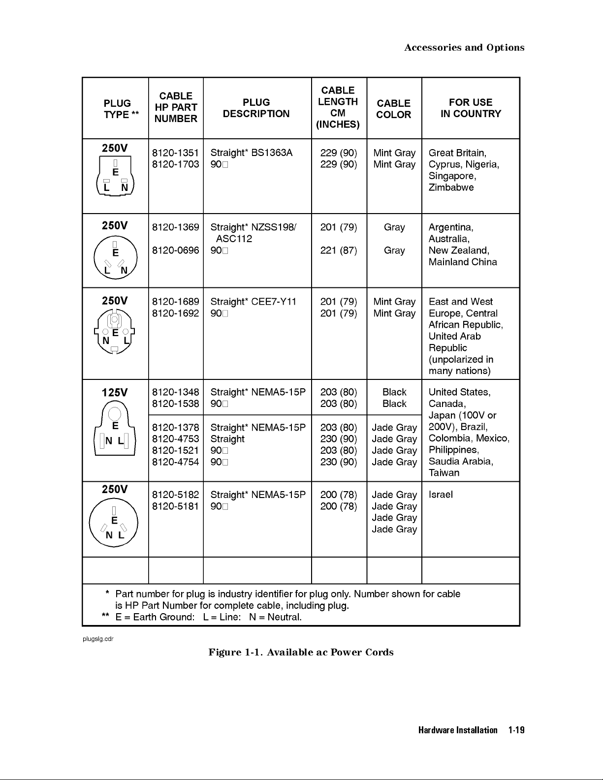
1-1. Available ac Power Cords . . . . . . . . . . . . . . . . . . . . . . . . . . 1-19
2-1. Line Voltage Selector . . . . . . . . . . . . . . . . . . . . . . . . . . . . 2-2
2-2. Line Fuse Removal and Replacement .................... 2-3
NNNNNNNNNNNNNNNNNNNNNNNNNNNNNNNNNNNNNNNN
N
2-3.
display tests
2-4.
Condence
2-5.
Key
T
est
Menu Keys ........................ 2-8
T
est
.............................. 2-9
..... ...... ..... ...... ...... ..... 2-10
2-6. Knob Test Display ...... ...... ...... ...... ..... 2-11
2-7. Display ID . . . . . . . . . . . . . . . . . . . . . . . . . . . . . . . . . 2-13
2-8. Typical Serial Number Label .... ...... ...... ...... .. 2-15
4-1. RAM Memory Card Battery Replacement .... ...... ...... .. 4-35
4-2.
5-1.
5-2.
5-3.
5-4.
5-5.
5-6.
Memory
Main
Hard
Mass
Example
Using
A
djust
Card
Date
Code
Keys
.
Copy
Storage
of
MSIB
Location
.
.
.
.
.
.
.
Keys
..... ...... ..... ...... ...... .. 5-6
Keys......... ...... ...... ...... .. 5-12
an HP 70900B Local Oscillator Source Accessing an HP-IB Disk Drive 5-13
to Connect the Display to a Remote Antenna Site ...... .. 5-13
.
.
.
.
.
.
...... ...... .... 4-36
.
........................ 5-3
Color Keys ........ ...... ...... ..... .... 5-15
5-7. Cong Display Keys ............................ 5-21
5-8. AddressMapKeys ............................. 5-26
5-9. Misc Keys . . . . . . . . . . . . . . . . . . . . . . . . . . . . . . . . . 5-29
Tables
1-1. Optional Accessories for the HP 70004A Color Display ............ 1-18
1-2. ITEL Interface Models ........................... 1-20
2-1. Default MSIB AddressMap... ...... ...... ...... .... 2-3
2-2. HP Service Centers .. ...... ...... ...... ...... .. 2-16
2-3. Packaging for an 8/8 Module (Color Display)................. 2-18
5-1. HP P
5-2. Mapping of Display P
5-3. Default Values of
aintJet Color Map . . . . . . . . . . . . . . . . . . . . . . . . . . .
ens to Plotter Pens................... 5-9
NNNNNNNNNNNNNNNNNNNNNNNNNNNNNNNNNNNNNN
copy options
...................... 5-11
5-4. Default Color Values for the Edit Colors Menu . . . . . . . . . . . . . . . . 5-17
5-5. Default V
5-6. Red, Green, and Blue V
5-7. Red, Green, and Blue V
alues for the Monochrome Display . . . . . . . . . . . . . . . . .
alues for Vision Enhnc 1 . . . . . . . . . . . . . . . 5-19
alues for Vision Enhnc 2 . . . . . . . . . . . . . . . 5-19
5-8. Red, Green, and Blue Values for the Optical Filter . . . . . . . . . . . . . . 5-20
5-7
5-18
Contents-3
Page 12

Page 13
Hardware Installation
This chapter contains information needed to prepare an HP 70004A color display for use in
an HP 70000 Series modular measurement system. The information presented is general in
nature; for more detailed information on cabling congurations, module placement, and MSIB
addressing, refer to the
Manual
.
HP 70000 Modular Spectrum Analyzer Installation and Verication
1
Step 1. Unpacking Your HP 70004A Color Display
Step 2 (Optional). Installing an Instrument Keypad
Step 3 (Optional). Installing HP-HIL Devices
Step 4. Connecting Rear Panel Cables
Step 5. Setting the MSIB and HP-IB Address
Step
6
Step
7
Step
8
Step
9
Step
10.
Step
11
A
ccessories
(Optional).
(Optional).
(Optional).
(Optional). Inserting a RAM Memory Card
Connecting the AC Line Power
(Optional). Running the Condence Tests
and Options
Connecting
Connecting
for
an
Remote
HP-IB
Connecting a printer
::::: ::::::: ::::::: :::::: ::::::: ::::::: ::::::: :::::: ::::::: ::::::: :::
::::: ::::::: ::::::: ::::::: :::::: ::::::: ::::::: :::
::::::: :::::: ::::::: ::::::: :::::: ::::::: ::::::: :::::: ::
::::::: ::::::: :::::: ::::::: ::::::: :::::: ::::::: :
HP-IB
Disk
Operation
Drive
:::::::::::::::::::::::::::::::::::::::::::::::::::::
:::::: ::::::: ::::::: :::::: ::::::: ::::::: ::::::: :::::
:::::: ::::::: ::::::: :::::: ::::::: ::::::: :::
:::::: ::::::: :::::: ::::::: ::::::: :::::: :::
:
:
:
:::::: ::::::: :::::: ::::::: ::::
:
:
:
:::::::::::::::::::::::::::::::::::::
:::::: :::::: ::::::: ::::::: ::::::: :::::: :::
:::::: ::::::: ::::::: :::::: ::::::: ::::::: ::
1-2
1-3
1-5
1-7
1-8
1-9
1-10
1-12
1-14
1-15
1-17
1-18
Hardware Installation 1-1
Page 14

Step
1
1.
Unpacking
Y
our
HP 70004A Color Display
Unpack your color display from its shipping container.
2
Inspect the shipping container and contents thoroughly to ensure that it was not damaged
during shipment.
If
the
container
both
mechanically
nearest
materials
Hewlett-P
for
or
the
cushioning
and
electrically
ackard
carrier's
material
Sales
and
inspection.
.
If
the
Service
is
damaged, check the contents of the shipment
contents are damaged or defective, contact your
Oce. (Refer to Table 2-2 .) Keep the shipping
3
Verify that all parts and materials were included in the shipping container
for HP part number listings
.)
. (Refer to Table 1-1
One: HP 70004A color display
One:
HP 70004A Color Display User's Guide
One Set: MSIB Rear Panel Cables
One: ACPower Cord
(Optional): HP-IB Rear Panel Cables
(Optional): Instrument Keypads
(Optional): HP-HIL devices
(Optional): Memory Cards
1-2 Hardware Installation
Page 15

Step
2
(Optional).
Installing
an
Instrument
K
eypad
Step
2
(Optional).
Installing
an
Instrument Keypad
To remove an instrument keypad (with release button):
1. Depress the release button, located on the right-hand side of the keypad, and the
instrument keypad should snap out.
To install a custom instrument keypad (with release button):
1. Insert the left side of the keypad (2) into the front panel.
2. Press the right side of the keypad until it snaps into the front panel.
Instrument keypads execute commonly used instrument functions and duplicate operation
of corresponding
4
MENU
5
softkeys.
There are two dierent release mechanisms for the blank panel:
If the blank panel has a release button on the right-hand side, use the procedure listed
above.
If the blank panel has a slot in the right-hand side, use the procedure on the following page
that utilizes a screwdriver.
Hardware Installation 1-3
Page 16

Step
2
(Optional).
Installing
an
Instrument
K
eypad
To remove an instrument keypad (without release button):
1.
2.
Insert
Gently
a
bladed
pry
screwdriver
the
screw-driver's
into the keypad's slot (1).
handle to the left. The keypad (2) will snap out of the front
panel.
To install a custom instrument keypad (without release button):
1.
2.
Insert
Press
the left side of the keypad (2) into the front panel.
the right side of the keypad until it snaps into the front panel.
Instrument keypads execute commonly used instrument functions and duplicate operation
of corresponding
4
MENU
5
softkeys.
There are two dierent release mechanisms for the blank panel:
If the blank panel has a release button on the right-hand side, use the procedure on the
previous page that utilizes a screwdriver.
If the blank panel has a slot in the right-hand side, use the procedure listed above.
1-4 Hardware Installation
Page 17

Step
3
(Optional).
Installing
HP-HIL
Devices
Step
To connect a HP-HIL keyboard and a mouse:
1. Inspect the two ends of each HP-HIL cable to locate an end with one black dot and an end
2. Plug the two-dot end of the HP-HIL cable into the display's two-dot connector.
3. Plug the one-dot end of the HP-HIL cable into the one-dot connector on the keyboard.
4. Plug the two-dot end of the HP-HIL cable that came with the HP mouse or track ball into
3
(Optional).
with two black dots.
The end with two black dots is always plugged into the two-dot connector of the device
you are linking from, while the one dot end is always plugged into the one-dot connector
of the device you are linking to.
the keyboard's two-dot connector.
Note
The HP mouse has only a two-dot end on its HP-HIL cable. Therefore it must be the last
device in the link.
Installing
HP-HIL
Devices
Hardware Installation 1-5
Page 18

Step
3
(Optional).
Installing
HP-HIL
To connect an HP mouse or track ball:
Plug
the
the
keyboard's
track
The
HP-HIL
track
ball
ball.
two-dot
do
end
two-dot
not
need
interface
of
the HP-HIL cable that came with the HP mouse or track ball into
connector
a keyboard, they can be connected directly to the display.
supports
most
Devices
or
the two-dot connector of the display; the HP mouse or
relative locator devices including the HP mouse and
1-6 Hardware Installation
Page 19

Step
4.
Connecting
Rear
P
anel
Cables
Step
To connect the display to another display or mainframe:
4.
Connecting
Rear
P
anel Cables
1;2
1. Connect an MSIB cable between the HP 70004A color display's MSIB OUT connector (1)
and the HP 70001A mainframe's MSIB IN connector (2).
2. Connect an MSIB cable between the HP 70001A mainframe's MSIB OUT connector (3) and
the HP 70004A color display's MSIB IN connector (4).
The MSIB cables are connected serially, coupling the input of one element to the output of
the next until the loop is completed.
3. The cabling shown in this diagram is for a generic spectrum analyzer system; for more
information about connecting cables between various modules used in an MMS system,
refer to the
HP 70000 Modular Spectrum Analyzer Installation and Verication Manual
.
1
Each MMS system is shipped with a unique set of precongured cables; the lengths of required cables may vary.
2
For information on connecting to an external monitor, refer to \Understanding RGB Video Outputs and Their Use"
in Chapter 9.
Hardware Installation 1-7
Page 20

Step
5.
Setting
the
MSIB
and HP-IB Address
To set the MSIB and HP-IB address switches:
1. Locate the address switches on the rear panel of the display.
2. Set the ve switches labeled COLUMN to the binary value of the display's MSIB column
address.
Setting the COLUMN address of the display, species both the MSIB address and the HP-IB
address of the display.
MSIB Address HP-IB Address
00000 0
00001 1
00010 2
00011 3
1
00100
T
o establish proper system function and MSIB communication, each element in a system must
4
be assigned a unique MSIB address. The MSIB address is selected with an 8-bit binary DIP
(dual in-line package) switch; this 8-bit binary DIP switch is preset for each module at the
factory and may not have to be changed unless you are using a custom addressing
conguration.
Note
Changing MSIB addresses requires an understanding of MSIB addressing rules. If you use a
custom addressing conguration, refer to the
Installation and V
1
The display section's MSIB COLUMN address is factory-preset to 4 and may be changed, but the display's MSIB ROW
erication Manual
.
HP 70000 Modular Spectrum Analyzer
address is permanently set to 0.
1-8 Hardware Installation
Page 21

Step
6
(Optional).
Connecting
for
Remote
HP-IB
Operation
Step
To operate the display remotely:
1. Locate the address switches on the rear panel of the HP 70004A color display.
2. Set the HP-IB switch to the ON position.
3. Connect an HP-IB cable between the HP 70004A color display's HP-IB connector (1) and
4. Connect an HP-IB cable between the HP 70001A mainframe's HP-IB connector (2) and
6
(Optional).
the HP 70001A mainframe's HP-IB connector (2).
your system controller's HP-IB connector (3).
Your system controller may be any computer/controller (for example,HP9000
Series 200/300 controller) that supports an HP-IB card.
Connecting
for
Remote HP-IB Operation
Hardware Installation 1-9
Page 22

Step
To connect an HP-IB disk drive
1. Locate the HP-IB address switches on the rear panel of the external HP-IB disk drive.
2. Set the HP-IB address switches to 0. Refer to the user's manual for your external HP-IB
3. Connect an HP-IB cable between the HP 70004A color display's HP-IB connector (1) and
7
(Optional).
disk drive if you use a dierent HP-IB address.
the external HP-IB disk drive's HP-IB connector (2).
Refer to Table 1-1 for recommended models of external HP-IB disk drives.
Connecting
an
HP-IB Disk Drive
1-10 Hardware Installation
Page 23

Step
7
(Optional).
Example of accessing an HP-IB disk drive through an HP 70900B local oscillator source.
Connecting
an
HP-IB
Disk
Drive
Example
of
using
MSIB
to
connect
to
a remote antenna site.
Hardware Installation 1-11
Page 24

Step
To connect a printer
1. Locate the printer address switches on the rear panel of the printer being connected.
2. Set the address switches to 1. Refer to the user's manual for your printer if you use a
3. Connect an HP-IB cable between the HP 70004A color display's HP-IB connector (1) and
4. Connect a Centronics printer cable between the \Centronics" connector (3) on the ITEL
8
(Optional).
dierent printer address.
the \HP-IB" connector (2) on the ITEL interface. (Refer to Table 1-2 for recommended
ITEL interface models.)
interface and the printer (4).
To connect a printer to the HP-IB port on the HP 70004A color display, an HP-IB to
Centronics
Bi-tronics
converter is required. The Centronics connector is used to connect to the
parallel
Connecting
port on the back of many Hewlett-Packard printers. (Refer to Table 1-2.)
a
printer
1-12 Hardware Installation
Page 25

Step
8
(Optional).
Connecting
a
printer
Hardware Installation 1-13
Page 26

Step
To insert a RAM memory card:
1. Locate the arrow printed on the card label.
2. Insert the card with the arrow on the card matching the arrow above the card-reader slot.
3. Press the card into the slot. When correctly inserted, approximately 19 mm (0.75 in) of
9
(Optional).
the card is exposed.
Inserting
a
RAM Memory Card
Memory cards provide storage media and access routines and instrument personalities; these
are called down-loadable programs (DLPs).
WARNING
Improper card insertion can cause error messages to occur, but generally does not
damage the card or instrument. Care must be taken, however, not to force the card
into the card reader slot.
1-14 Hardware Installation
Page 27

Step
10.
Connecting
the
A
C
Line
P
ower
Step
1
10.
Connecting
the
A
CLinePower
Conrm that the line-voltage selector is set to the proper ac line voltage.
Failure to set the ac power input to the correct voltage could cause one of two things to
happen when power is applied:
If the switch is set to 115 V and the instrument is connected to 230 V, the fuse will blow.
If the switch is set to 230 V and the instrument is connected to 115 V, the instrument will
not turn on.
WARNING
Before turning this instrument on, make sure the line-voltage selector is set to the
voltage of the ac power source.
115 V position for 90 to 132 Vac line input voltages at 50, 60, or 400 Hz
230 V position for 198 to 264 Vac line input voltages at 50 or 60 Hz
Also make sure that it is grounded through the protective conductor of the ac power cable to
a socket outlet provided with protective earth contact. Any interruption of the protective
(grounding) conductor inside or outside the instrument, or disconnection of the protective
earth terminal, can result in personal injury.
Hardware Installation 1-15
Page 28
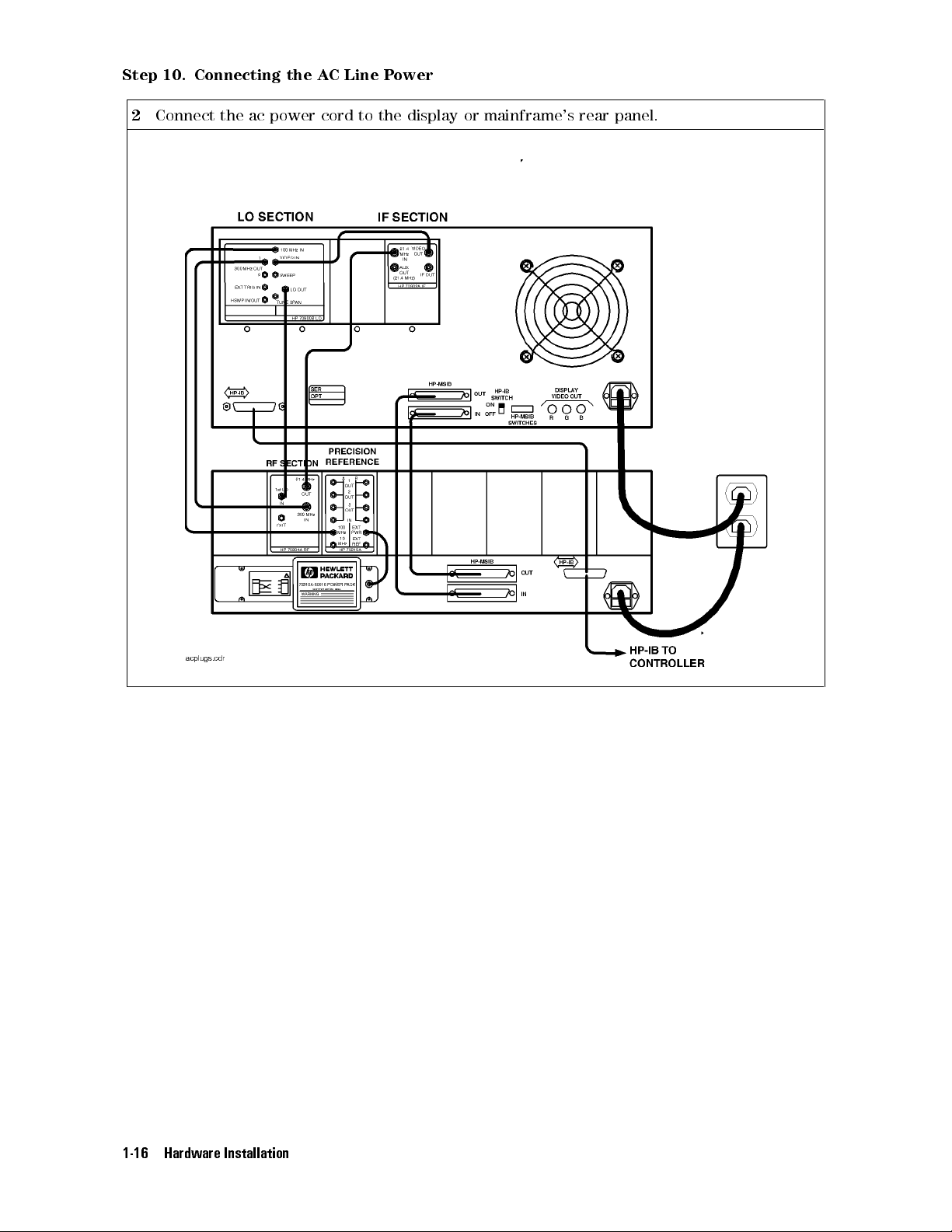
Step
10.
Connecting
2
Connect the ac power cord to the display or mainframe's rear panel.
the
A
C
Line
P
ower
1-16 Hardware Installation
Page 29

Step
11
(Optional).
Running
the
Condence
T
ests
Step
1
2
11
Press the
Press the
(Optional).
5
4
DISPLA
NNNNNNNNNNNNNN
Misc
key.
Y
NNNNNNNNNNNNNNNNNNNNNNNNNNNNNNNNNNNNNNNNN
,
display tests
Running
,and
the
Condence Tests
NNNNNNNNNNNNNNNNNNNNNNNNNNNNNNNNNNN
CONFID TEST
menu keys to initiate the test.
The Condence Test checks the operation of roughly 90% of the HP 70004A color display.
If the HP 70004A color display fails the Condence Test, it attempts to write anE(error) in
the system state area of the display.
3
Verify that
6001 Confidence test passed
appears in the lower-left corner of the screen.
If the display passes the Condence Test, and the display screen shows no visible
distortion, there is a high level of probability that the display is functioning correctly.
If a fault is found,
6008 Confidence test failed
is displayed. In this event, refer to \If
You Need to Run Display Tests" in Chapter 2 for additional information, or contact your
nearest Hewlett-Packard Sales and Service Oce. (Refer to Table 2-2.)
At power-on, a set of tests that is dierent from the Condence Test is run. The set of
tests run at power-on includes tests for the MSIB capability of the display. The display
indicates whether any of these tests fail, but does not indicate if they pass
.AnMSIB
failure is indicated by a blinkingE(error) indicator in the system state area of the display.
If the Condence Test produces errors and the MSIB is working (no blinkingEindicator),
error messages produced by the Condence Test can be viewed by pressing the
NNNNNNNNNNNNNNNNNNNNNNNNNNNNNNNNNNNNNNNNN
and
REPORT ERRORS
.
4
DISPLAY
5
Hardware Installation 1-17
Page 30

A
ccessories
The
accessories
part
of
a
precongured
and
that
Options
are
supplied
HP
70000
with
Series
an
HP
modular
70004A color display, ordered separately,oras
measurement system are the same.
When
ordered
with
a
precongured
HP
70000
Series
modular measurement system, cables are
supplied to connect the modules in the particular conguration; for information on dierent
congurations
Spectrum
or
specic
Analyzer
T
able
cable
Installation
1-1.
Optional
lengths and HP part numbers, refer to the
and
Verication Manual
.
HP 70000 Modular
Accessories for the HP 70004A Color Display
Group Description HP Part Number
Options
Instrument
K
eypads
Option 913 Rack mount with handles
Option 908 Rack mount without handles
Option 010 Rack slide
HP
70820A
microwave
1
transition
1
analyzer
1
HP 5062-3979
HP 92576
HP
70820-60086
HP 5062-4073
HP 70874A eye diagram analyzer personality DLP HP 70874-60002
HP 70900A/B local oscillator source HP 70900-60208
HP 70950A optical spectrum analyzer HP 70950-60033
HP-HIL Devices
Keyboard HP 46021A
Keyboard HP
HP-HIL
cable
2
98203C
HP
46020-60001
Track ball HP M1309-60001
HP-IB
Disk
Drives
3.5
"
disk
drive
HP
9122C
Hard disk drive HP 9153C
Memory
Cards
32
KB
RAM
with
battery
HP
85700A
128 KB OTP3ROM with battery HP 85701A
128 KB RAM with battery HP 85702A
256 KB OTP3ROM HP 85703A
256
KB
RAM
HP
85704A
512 KB RAM HP 85705A
KB
3
ROM HP
OTP
85706A
4
HP
to
BNC
A
dapter
(3
required)
1250-1853
ACPower Cables
A
dapters
Hex Ball Driver
Thin-Film Cleaner
MSIB Cables
5
512
Power cable Refer to Figure 1-1.
RCA
8 mm hex ball driver HP 8710-1651
Video Clean Kit HP 92193
HP 70800A 0.5 m MSIB cable
HP 70800B 1.0 m MSIB cable
HP 70800C 2.0 m MSIB cable
HP 70800D 6.0 m MSIB cable
HP 70800E 30.0 m MSIB cable
HP 70207-60003 2.5 m MSIB Y-cable
HP 70207-20003 MSIB cable adapter (2 Quantity)
1
For information on how to rack mount your system, refer to the instructions in
Modular Spectrum Analyzer Installation and Verication Manual
2
This HP-HIL cable is used to connect an HP-HIL keyboard to the HP-HIL connector on the
front panel of the HP 70004A color display.
3
This memory card is One Time Programmable (OTP) Read Only Memory (ROM) .
4
The HP part number of the required ac power plug depends on the country of use.
5
To order MSIB cables, in lengths up to 1.2 km, contact Hewlett-Packard. (Refer to \If You
Need to Contact Hewlett-Packard" in Chapter 2.)
1-18 Hardware Installation
HP 70000
.
Page 31
A
ccessories
and
Options
Figure 1-1. Available ac Power Cords
Hardware Installation 1-19
Page 32

A
ccessories
and
Options
ITEL Interface Models for Connecting Printers
There are a number of Centronics converter models available for connecting printers to the
HP-IB. These models are made by Intelligent Interfaces Inc. (800-842-0888) and are listed in the
following table.
Table 1-2. ITEL Interface Models
V
ersion
Model
1
Transfer
Rate
Domestic ITEL
MicroPlot
50
3
35
KB/sec
to
2
;
50 KB/sec
Domestic ITEL MicroPrint 45CV
Domestic ITEL MicroPrint 45CXA
Domestic ITEL MicroPrint 45CHVU
International ITEL
MicroPrint
45CHVE
4
2;5
2;6
7
30 KB/sec
30 KB/sec
15 KB/sec
15
KB/sec
2
;
Adapters
F1011A
F1011A
#ABB
#ABU
(EUROPE)
(UK)
F1011A #ABG (AUS)
F1011A #ACQ (S. AFRICA)
1
T
o order various models, contact HP DIRECT 1-800-538-8787.
2
ITEL
MicroPlot
50
is
a
product
of
Intelligent Interfaces Inc.This
model comes with the appropriate ac transformer for use in
North America, Japan, Korea, and Taiwan.
3
This
model
4
ITEL
emulates
MicroPrint
Hewlett-Packard plotters.
45CV
is
a
product
of
Intelligent
Interfaces
This model puts LaserJets in HPGL mode without the need to
set DIP switches like those used with the Model ITEL MicroPrint
45CXA.
5
ITEL MicroPrint 45CXA is a product of
Intelligent Interfaces Inc. This unit can be ordered with a
variable
resolution
option
which
allows
the resolution of the
printer to be set via DIP switches (it sends the appropriate
escape sequences). This option is useful when the printer
defaults to high-resolution mode which can cause a printout
to be about the size of a postage stamp. This is a common
occurrence when other HP-IB instruments dump traces to
DeskJet P
6
ITEL MicroPrint 45CHVU is a product of
ortable printers
.
Intelligent Interfaces Inc.
7
ITEL MicroPrint 45CHVE is a product of
Intelligent Interfaces Inc
. This model is for international use
and does not come with a particular ac transformer; an ac
transformer must be ordered separately.
Inc
.
1-20 Hardware Installation
Page 33

2
If You Have Problems
This section contains information to help identify and resolve some common problems that may
occur with your color display before the need for extensive servicing.
Symptoms of various problems are listed at the top of each page. Most symptoms have a brief
description or explanation to help provide more insight into their cause. A possible cause for
the symptom and a checklist of possible solutions are then presented. Use this checklist as an
aid to correct the problem.
If the System's Power-On Self Test Fails
If You Have a Blank or Distorted Display
:::::: ::::::: ::::::: :::::: ::::::: ::::::: :::::: :::::::
::::::::::::::::::::::::::::::::::::::::::::::::::::
If One of the HP 70004A Color Display Fault Indicators is On
If More Than One Module's Error Indicator is Flashing
If
Y
ou
Need
to
Run
If
Y
ou
Need to Contact Hewlett-Packard
Returning
Display
Y
our Color Display to Hewlett-Packard
T
ests
:
:
:::::: ::::::: :::::: ::::::: ::::::: ::::::: :::::: ::::::: ::::::
::::::: :::::: ::::::: ::::::: :::::: ::::::: ::::::: :::::
:::::: ::::::: ::::::: :::::: ::::::: :::::
::::: ::::::: :::::: ::::::: ::::::: ::::::: :::
:::::: ::::::: ::::::: :::::: :::::
2-2
2-4
2-5
2-7
2-8
2-14
2-16
If You Have Problems 2-1
Page 34

If
the
Each
time
through
on
each
System's
the
HP
an
initializing
module
ash
70000
on
P
ower-On
Series
routine
(power-on
momentarily
modular
Self Test Fails
spectrum
self
and
then
analyzer system is turned on, the system runs
test)
during
turn o.
which the front panel STATUS LEDs
The display also executes a power-on self-test when power is applied. If the test fails, the
display
of
system
area
The
terminates
the
instrument
bus
located
following
(MSIB).
in
the
conditions
the
sequence
functions
The
results of the test can be determined by examining the system state
and displays an error on the screen in large block letters.One
tested is the ability of the display section to communicate on the
upper-left corner of the display screen.
for the display section should exist after the power-on self-test:
The MSIB fault indicator should be o.
The display's fan noise will be scarcely noticeable.
If the system passes the power-on self test, the MEASURE LED on the local oscillator module
begins blinking on and o (triggered by the system sweep), and the ACT LED on each active
module's
front panel is turned on.
Common
If
problems
any
module fails the power-on self test, it will not establish a link with the display.
that may occur:
If the front panel LEDs on the HP 70900A/B local oscillator source ash on and o, it means
the instrument has failed the power-on self test.
If the display section's power-on self test fails, a blinkingEwill appear in the status box of
the display.
This error is the same as the red LED marked \ERR" on other HP 70000 Series modules.Its
purpose
T
o
solve
Check
Check
is
these
that
that
to
indicate
common
the
HP
the
HP
an
error
problems:
70900A/B
70000
Series
detected
local
oscillator
modular
in
the
system on MSIB row 0 of the address map.
source
spectrum
is powered on.
analyzer system display and mainframe
are plugged into the proper ac line voltage.
Check that the line socket has ac line voltage.
Check that the line voltage selector switch is set to the correct voltage for the ac line voltage
being used. The line voltage selector switch is located on the left side of the HP 70004A
color display, on the bottom of the HP 70001A mainframe.
Figure 2-1. Line Voltage Selector
Check the line fuse on the display or the mainframe to ensure that it is not damaged. The
line fuse is located inside the power-cord receptacle housing on the rear of the display and
2-2 If You Have Problems
Page 35

If
the
System's
P
ower-On
Self
T
est
Fails
mainframe. Also included in this housing is a spare fuse. The fuse is a 5 by 20 mm fuse rated
at 6.3 A, 250 V (HP part number 2110-0703). This line fuse can be used with both 120 V and
230 V line voltage.
Figure 2-2. Line Fuse Removal and Replacement
Check the system interconnections.
Check the address map as shown in Table 2-1.
Run the Condence Test. (Refer to \If You Need to Run Display Tests".)
The Condence Test checks the operation of about 90% of the display.
If the Condence Test runs successfully, the rst error was probably a system failure,not a
display
failure
.
If necessary, obtain service from Hewlett-Packard. Refer to \If You Need to Contact
Hewlett-P
ackard".
T
able
2-1.
Default
Column
Row 7
Row 6
RF sections
Row5HP
Row 4
Row 3
Row 2
Row 1
Row 0
1
This includes: HP 70904A RF section, HP 70905A/B RF section,
18
blank HP 70310 blank
1
70907
HP 70903 blank HP 70810 Option 850
HP 70911 HP 70620 or HP 70621
HP 70700 HP 70600 or HP 70601 blank
HP 70902 blank blank
HP 70900 blank blank
MSIB
Column
19
A
ddress
Map
Column
HP 70300 HP 70620 or HP 70621
HP
70301
3
blank
HP 70810
20
2
HP 70906A/B RF section , HP 70908A RF section, HP 70909A or
HP 70910A RF section.
2
When preamplifying the lightwave section's input signal.
3
When preamplifying the preselector's or RF section's input signal.
For more information about addressing criteria, refer to
Installation and Verication Manual
.
HP 70000 Modular Spectrum Analyzer
If You Have Problems 2-3
Page 36

If
Y
ou
T
o
solve
V
erify
V
erify
If
necessary
Hewlett-P
Have
this
problem:
that
that
ackard".)
your
the
,
obtain
a
Blank or Distorted Display
display
intensity
is
powered
is
turned
on.
on.
service from Hewlett-Packard. (Refer to \If You Need to Contact
2-4 If You Have Problems
Page 37

If
One
of
the
If
One
of
the
HP
70004A
HP
70004A Color Display Fault Indicators is On
Color
Display
Fault Indicators is On
Problems
The
An
A
A
A
external
HP
70004A
MSIB
blinking
steady
red
battery-low
to
the
display
color
display
indicator
red
red
on
the
E
in the status box in the upper-left corner of the display.
E
in the status box in the upper-left corner of the display.
indicator
can
cause
the
indicators to turn on.
has
four
fault
indicators:
upper-left
corner
of
the front panel.
next to the RAM memory card access slot.
If you have an MSIB fault indicator on
The HP 70004A color display has an MSIB system fault indicator in the upper-left corner of
the front panel. This indicator applies to the I/O backplane and all modules in the system,
not just the display system; the MSIB indicator should be OFF indicating normal operation.
This circuitry senses the readiness of the external MSIB. If the MSIB indicator light is on,
MSIB communications are inhibited and the condition must be cleared before the display will
operate.
The
MSIB indicator light will be on if one of the following conditions is true:
The external MSIB loop is not complete.
Check that both ends of all MSIB cables are securely connected.
If more than one mainframe is used, or if other elements are connected to the MSIB, all
cables must be connected; otherwise, the MSIB will not operate. If a single mainframe with
no external elements is used, there should be no MSIB cables connected to the external MSIB
connectors of that mainframe, although a single cable looped from the input connector to the
output connector will allow the mainframe to operate.
Not
all
the
V
erify
external
T
o
isolate
that
MSIB
the
elements
the
.
problem:
power
on
the
external
is
on
to the display, all mainframes, and stand-alone instruments on the
MSIB
loop have the power turned on.
Disconnect both MSIB cables from the display rear panel. Is the MSIB indicator light still on?
NO
The problem is either with the cables or an element that was connected to the display
with the cables.
Loop each cable (one at a time) from
the display MSIB IN to OUT connectors. If the
MSIB indicator comes on, that cable has probably failed. If the light does not come on
for any of the cables, then an element connected with these cables is faulty.Ifan
element is determined to be at fault, contact your nearest Hewlett-Packard sales and
service oce for repair.
YES
The HP 70004A color display is probably faulty. Contact your nearest Hewlett-Packard
sales and service oce for repair.
If You Have Problems 2-5
Page 38

If
One
of
the
HP
70004A
Color
Display
Fault Indicators is On
If you have a blinkingEindicator
TheEindicator in the status box in the upper-left corner of the display is the same as the red
LED marked \ERR" on other HP 70000 Series modules. Its purpose is to indicate an error
detected in the system on MSIB row 0 of the address map. A blinkingEor ERR LED has a
special meaning: it signies that a problem on the MSIB backplane has been detected during
system power-up which may prevent normal communication between any modules (and hence,
normal
operation
error
can
reporting).
take
place
Such
.
a
problem
must
be
resolved
before
any predictable system
Remove
and
1.
2.
all
MSIB
cycle
power
If
the
red
E
sales
and service oce.
cables
.
indicator on the display still blinks, then contact your nearest Hewlett-Packard
from
the
display's rear panel, all modules from the mainframe section,
If theEindicator does not blink, then connect a known good MSIB cable between the rear
panel
MSIB IN and OUT connectors and cycle power.IftheEnow blinks, contact your
nearest
Hewlett-Packard sales and service oce for repair.
3. If the redEindicator stops blinking, insert the modules one by one until theEstarts
blinking. When the indicator starts blinking, check the modules for the same MSIB address.
4.
If
the
E
indicator
refer
to
either
HP
70205A
Verication Manual
doesn't
the
HP
Graphics
blink, the problem is probably in another display or mainframe,
70001A Mainframe Installation and Verication Manual
Display
and
HP 70206A System Graphics Displays Installation and
for more information about mainframe troubleshooting.
or the
5. If the cursor (rectangle) cannot be moved about within the address map after a module has
been re-addressed, check to see if two modules have the same row and column address.If
so, removal of one of the oending modules is required. See the Installation and Verication
Manual for your instrument for instructions.
MSIB
addresses
must
be
unique
.
Setting
two
HP
70000
Series
modular
measurement
system elements to the same address will create an error and make the system bus (MSIB)
inoperative.
If you have a steadyEindicator
NNNNNNNNNNNNNNNNNNNNNNNNNNNNNNNNNNNNNNNNN
5
A
module
(or
the
display)
has detected an error. Press
to identify the modules reporting errors. (Refer to the
4
DISPLAY
N
N
N
NNNNNNNNNNNNNNNNNNNNNNNNNNNNNNNNNNNNNN
REPORT ERRORS
and
REPORT
key for more
ERRORS
information.)
If you have a RAM memory card battery-low indicator light on
The display has a RAM memory card battery-low fault indicator near the memory-card slot in
the lower-right corner of front panel.
The battery-low indicator will indicate on if the battery voltage is too low
. The
battery-low indicator will be o if there is no RAM memory card in the slot or if a
one-time-programmable ROM memory card is being used.
2-6 If You Have Problems
Page 39

If
More
Than
One
If
More
The
HP
analyzer
ashes
Than
70004A
system
at
a
1
Hz
color
over
rate
Module's
One
,
Module's
display
the
the
communicates
MSIB
.
When
module cannot communicate over the MSIB.
Error Indicator is Flashing
with
the
HP 70000 Series modular spectrum
the
STATUS ERR indicator LED on a particular module
Error
Indicator
is
Flashing
To solve this problem:
Try
turning
If
front
located
If
front
o
the
power to the system and then turning it on again.
panel
keys
are still responding, check the address map to see that all modules are
in
their
designated
panel
keys are not responding and the address map cannot be checked, power-down
coordinates.
the system, pull out each module and check its address setting by looking at its address
switches.
All modules should conform to the required coordinates on the address map. (Refer to
Table 2-1.)
If your system contains more than one mainframe, check that the MSIB cables are connected
such
that two cable connections are made to each mainframe. If these cable connections
look
correct,
If
necessary
Hewlett-P
you may try replacing the MSIB cables with new ones.
, obtain service from Hewlett-Packard. (Refer to \If You Need to Contact
ackard".)
If You Have Problems 2-7
Page 40

If
Y
ou
The
Need
Display
T
ests
to
are
is accessed by pressing
Run Display Tests
the
display
4
DISPLAY
diagnostic
NNNNNNNNNNNNNN
5
Misc
and adjustment routines. The Display Tests screen
NNNNNNNNNNNNNNNNNNNNNNNNNNNNNNNNNNNNNNNNN
display tests
.
W
ARNING
Keep in mind that display internal adjustments or repairs should only be
attempted by qualied technical personnel.
N
N
N
N
N
N
N
N
N
N
NNNNNNNNNNNNNNNNNNNNNNNNNNNNNNN
Figure
2-3.
display
tests
Menu
K
eys
2-8 If You Have Problems
Page 41

If
Y
ou
Need
to
Run
Condence Test (
W
WWWWWWWWWWWWWWWWWWWWWWWWWWWWWWWWWWWWWWWWWWWWW
CONFID TEST
Display
Menu Key)
T
ests
NNNNNNNNNNNNNNNNNNNNNNNNNNNNNNNNNNN
Initiate the Display Condence Test by pressing the
T
est
checks
test
confidence
T
o
run the Display Condence Test:
1.
Press
passed
4
DISPLA
the
operation
of
roughly 90% of the display. If no fault is found,
appears in the lower-left corner of the screen. If a fault is found,
test
N
5
Y
failed
N
N
N
N
Misc
N
N
N
N
NNNNNN
is displayed.
N
N
N
N
N
N
NNNNNNNNNNNNNNNNNNNNNNNNNNNNNNNNNN
display
tests
N
N
N
N
N
N
N
NNNNNNNNNNNNNNNNNNNNNNNNNNNN
CONFID
CONFID TEST
TEST
.
menu key. The Condence
6001 confidence
6008
If an error is detected, contact your nearest Hewlett-Packard service oce.
If
the
display
there
is
the
Condence
If
the
MSIB
pressing the
a
high
is
passes
level
T
est,
working,
4
DISPLAY
the
Condence
of
probability
it
attempts
any
error
NNNNNNNNNNNNNNNNNNNNNNNNNNNNNNNNNNNNNNNNN
5
and
REPORT ERRORS
T
est,
that
to
write
messages
and the display screen shows no visible distortion,
the display is functioning correctly. If the display fails
E
(error) in the display status block.
produced by the Condence Test can be viewed by
.
At power-on, a set of tests that is dierent from the Condence Test is run. The set of tests
run at power-on includes tests for the MSIB capability of the display. The display indicates
whether any of these tests fail, but does not indicate if they pass. An MSIB failure is indicated
by a blinkingE(error) indicator in the status block.
Figure 2-4. Condence Test
If You Have Problems 2-9
Page 42

If
Y
ou
Need
to
Run
Display
Key Test Menu Key
N
NNNNNNNNNNNNNNNNNNNNNNNNN
The
every
T
o
run
1.
Press
KEY TEST
front
the
4
menu key allows the user to check the mechanical and electrical operation of
panel
key
key
test:
NNNNNNNNNNNNNN
5
DISPLAY
Misc
T
ests
on
the
display
NNNNNNNNNNNNNNNNNNNNNNNNNNNNNNNNNNNNNNNNN
display
tests
.
NNNNNNNNNNNNNNNNNNNNNNNNNN
KEY
TEST
.
2. Press any key on the display's front panel. The pressed key will be
the key is working properly.
3. Press the backspace key
4 5
to exit the Key Test.
If an error is detected, contact your nearest Hewlett-Packard service oce.
echoed
on the screen if
2-10 If You Have Problems
Figure
2-5.
K
ey
T
est
Page 43
If
Y
ou
Need
to
Run
Display
T
ests
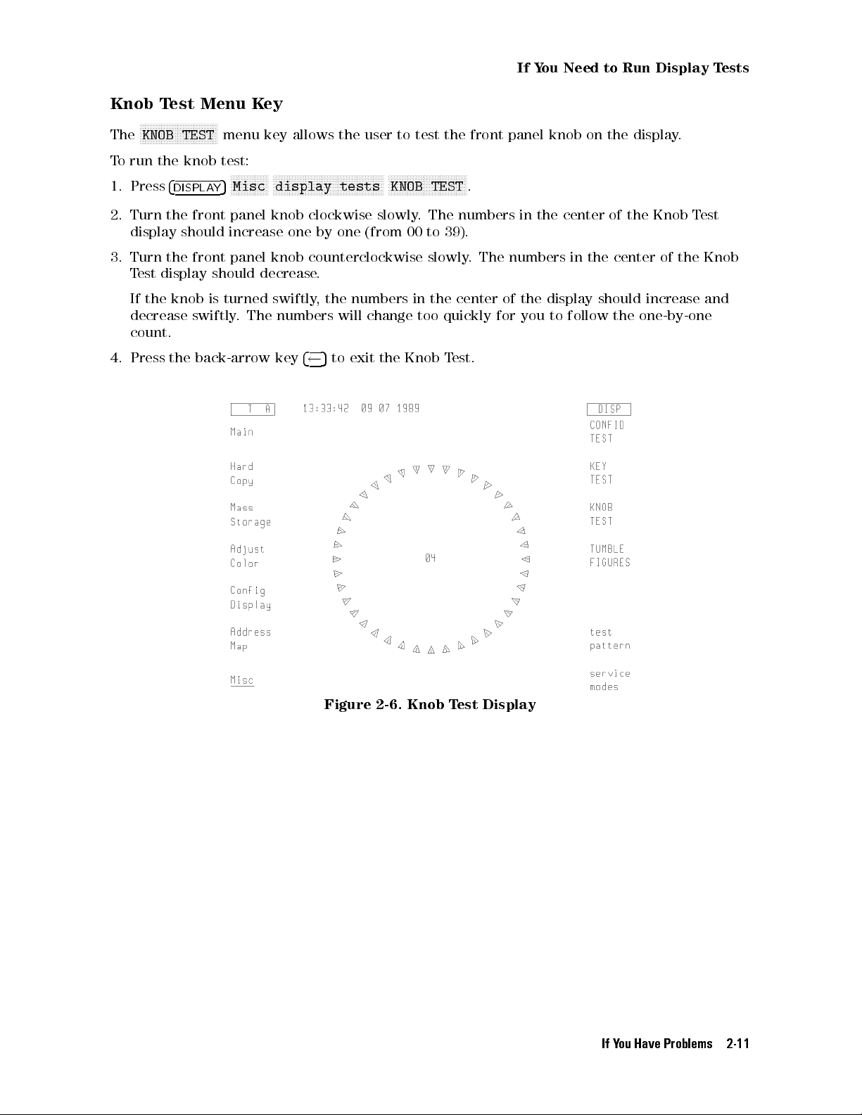
Knob Test Menu Key
N
NNNNNNNNNNNNNNNNNNNNNNNNNNNN
The
T
o
1.
run
Press
KNOB TEST
the
4
DISPLAY
menu key allows the user to test the front panel knob on the display.
knob
test:
NNNNNNNNNNNNNN
5
NNNNNNNNNNNNNNNNNNNNNNNNNNNNNNNNNNNNNNNNN
Misc
display
tests
NNNNNNNNNNNNNNNNNNNNNNNNNNNNN
KNOB
TEST
.
2. Turn the front panel knob clockwise slowly. The numbers in the center of the Knob Test
display should increase one by one (from 00 to 39).
3. Turn the front panel knob counterclockwise slowly. The numbers in the center of the Knob
Test display should decrease.
If the knob is turned swiftly, the numbers in the center of the display should increase and
decrease swiftly. The numbers will change too quickly for you to follow the one-by-one
count.
4. Press the back-arrow key
4 5
to exit the Knob Test.
Figure 2-6. Knob Test Display
If You Have Problems 2-11
Page 44

If
Y
ou
Need
to
Run
Display
T
ests
Tumble Figures Menu Key
Note
While the tumble gures are running, the display cannot communicate on
either
except
HP-IB
the
back-arrow
or
MSIB
.
Nor can the display respond to any front panel keys
5
key
and
4
NNNNNNNNNNNNNNNNNNNNNNNNNNNNNNNNNNNNNNNNNNNN
TUMBLE
the
FIGURES
menu
keys
select the various demonstration gures.
N
N
N
N
N
N
NNNNNNNNNNNNNNNNNNNNNNNNNNNNNNNNNNNNNN
The
TUMBLE
FIGURES
key
allows
the user to chose ve dierent demonstration routines:
To run the tumble gures test:
1.
2.
Press
Press
4
DISPLAY
one
of
5
the
Misc
NNNNNNNNNNNNNNNNNNNNNNNNNNNNNNNNNNNNNNNNN
display tests
following
menu
NNNNNNNNNNNNNNNNNNNNNNNNNNNNNNNNNNNNNNNNNNNN
TUMBLE FIGURES
N
N
N
N
N
N
N
N
NNNNNN
keys:
CUBE
N
,
N
N
N
N
N
N
N
NNNNNN
BALL
N
,
.
N
N
N
N
N
N
N
NNNNNN
SLAB
,
N
N
N
N
ROD
N
N
N
N
N
N
or
N
N
NNNNNN
HALF
.
N
N
N
N
NNN
,
NNNNNNNNNNNNNN
The tumble gures become larger or smaller when the front panel knob is turned.
3. To exit the tumble gures, press the
4 5
key.
Test Pattern Menu Keys
This key provides a menu of test patterns which are used to adjust the display.For
explanations of the test patterns and related adjustments, refer to the
Guide
.
HP 70004A Service
used
to
2-12 If You Have Problems
Page 45

Display ID Menu Key
N
NNNNNNNNNNNNN
Misc
When the
4
DISPLA
5
Y
information:
16
HP
squares
model
with
number
each
.
of
N
NNNNNNNNNNNNNNNNNNNNNNNNNNNNNNN
DISPLAY ID
the
current
If
Y
ou
Need
to
Run
Display
keys are pressed, the screen shows the following
colors
T
ests
Firmware
MSIB
HP-IB
version.
address
address
.
(OFF if disabled with the rear panel switch).
Custom Keypad ID Code.
Figure 2-7. Display ID
If You Have Problems 2-13
Page 46

If
Y
ou
T
o
clean
T
o
avoid
Hewlett-P
cleaning
Have
the
display's
damaging
ackard
cloth.
to
Clean the Display's Screen
screen
the
Video
coating
Clean
on the display screen, use a thin-lm cleaner such as
Kit
(HP
part number 92193). The kit includes an abrasion-free
2-14 If You Have Problems
Page 47

If
Y
ou
Need
to
Contact Hewlett-Packard
If
Y
ou
Need
to
Contact
Hewlett-P
ackard
Before
information.
In
calling
any
correspondence
Hewlett-P
W
arranty
ackard
or
information
or
telephone
returning
is
printed
conversations
your
at
color
display, please read your warranty
the
front of this document.
,
refer
to the color display by its full model
number and full serial number. With this information, the Hewlett-Packard representative can
determine
whether
your
unit
is still within its warranty period.
Determining Your Color Display's Serial Number
When a module is manufactured by Hewlett-Packard, it is given a unique serial number. This
serial number is attached to a label on the front frame or front panel of the module. A serial
number label is in two parts. (Refer to Figure 2-8.)
The rst part makes up the serial number prex and consists of four digits and a letter. The
second part makes up the serial number sux and consists of the last ve digits on the serial
number label. The serial number prex is the same for all identical modules; it only changes
when a change in the electrical or physical functionality is made. The serial number sux,
however, changes sequentially and is dierent for each module.
Figure 2-8. Typical Serial Number Label
If You Have Problems 2-15
Page 48

If
Y
ou
Need
to
Contact
Hewlett-P
ackard
A current list of Hewlett-Packard Service Centers can be accessed on the Internet at:
http://www.tmo.hp.com/tmo/contacts/
If you do not have access to the Internet, one of the following Hewlett-Packard locations can
direct you to your nearest Hewlett-Packard representative:
Table 2-2. HP Service Centers
United
States
Hewlett-Packard Company
Test and Measurement Call Center
24
Inverness
Place
East
Englewood, CO 80112
(800) 403-0801
(800)
Canada
857-8161
Hewlett-P
ackard
(F
AX)
Canada
Ltd.
5150 Spectrum Way
Mississauga, Ontario L4W 5G1
(905)
206-4725
(905) 206-4739 (FAX)
Europe
Hewlett-Packard European Marketing Centre
Postbox 667
1180 AR Arnstelveen
Netherlands
(31/20)
547-6669
(31/20)
647-8706
Japan
Hewlett-Packard Japan Ltd.
27-15, Yabe 1-Chome,
Sagamihara,
Kanagawa
229
Japan
(81426) 567 832
(81426)
567 843 (FAX)
Latin
America
Hewlett-P
5200
Blue
ackard
Lagoon
Latin
Drive
America
,
9th
Floor
Region
Headquarters
Miami, Florida 33126
U.S.A.
(305)
267
4245
(305) 267 4288 (FAX)
Austrailia/New
Zealand
Hewlett-P
ackard
Calibration
Services
A
ustrailia
Ltd.
31-41 Joseph Street
Blackburn, Victoria 3130
A
ustrailia
1800 802 540
1800 681 776 (FAX)
Asia-Pacic
Hewlett-Packard Asia-Pacic Ltd.
17-21/F Shell Tower, Times Square
1 Matheson Street, Causeway Bay
Hong Kong
(852) 25 997 777
(852) 25 069 261 (FAX)
2-16 If You Have Problems
Page 49

Returning
Y
our
Color
Display
to
Hewlett-P
ackard
Returning
Hewlett-P
your
color
nearest
Hewlett-P
ackard
display
Y
our
has
.
ackard
T
o
sales
Color
and
obtain
sales
Display
service
servicing
and
service
to Hewlett-Packard
oces
around
the world to provide complete support for
information or to order replacement parts, contact the
oce
listed
in Table 2-2.
Use the following procedure to return your color display to Hewlett-Packard:
1.
Fill
out
a
service tag (available at the end of this document) and attach it to the instrument.
Please
of
the
any
be
as
specic
following
error
messages
as possible about the nature of the problem. Send a copy of any or all
information:
that appeared on the HP 70000 Series display
a completed Performance Test record
any other specic data on the performance of the color display
CAUTION
Damage can result if the original packaging materials are not used. Packaging
materials should be anti-static and should cushion the color display on all sides.
Never
adequately
container
static
use
styrene
pellets
in
any
shape
as
packaging materials. They do not
cushion the instrument or prevent it from moving in the shipping
.
Styrene
electricity
pellets can also cause equipment damage by generating
or
by lodging in fan motors.
2. Place the color display in its original packaging materials.
If the original packaging materials are not available, you can contact a Hewlett-Packard
sales and service oce to obtain information on packaging materials or you may use an
alternative packing material referred to as \bubble-pack". One of the companies that makes
bubble-pack
is
Sealed
Air
Corporation
of
Hayward,
California,
94545.
3.
Surround
bubble-pack
4.
Place
container
with
The
color
5.
Seal the shipping container securely with strong nylon adhesive tape.
the
color
display
to
prevent
the
color
display
or
a strong shipping container that is made of double-walled corrugated cardboard
159
kg (350 lb) bursting strength.
shipping
container must be both large enough and strong enough to accommodate your
the
,
after
with
at
color
wrapping
least
display
3
it
to
4
inches of its original packing material or
from
moving
with
packing material, in its original shipping
in
its
shipping
container.
display and allow at least 3 to 4 inches on all sides for packing material.
6. Mark the shipping container \FRAGILE, HANDLE WITH CARE" to help ensure careful
handling.
7. Retain copies of all shipping papers.
If You Have Problems 2-17
Page 50

Returning
Y
our
Color
Display
to
Hewlett-P
ackard
Table 2-3. Packaging for an 8/8 Module (Color Display)
Item Description HP Part Number Qty
2-18 If You Have Problems
1 Corrugated
2 F
oam
3 Flat End-Cap 9220-4962 1
4 Static Sheet 9222-1806 1
5 Front Cover 5040-6974 1
6 Foam Plastic 4208-1210 1
7 Corrugated P
8 Corrugated Carton (Outer) 9211-7065 1
Carton
Corner-Pads
ad
(T
op)
9211-6785 1
5040-6967 8
9220-5072 1
Page 51

Introducing the HP 70004A Color Display
Summary
chapter
you
will learn about:
In
this
Main features of the HP 70004A color display.
Regions of the display screen, and the kinds of information that can be found
in each region.
Front panel hard-labeled keys and their use.
Instrument keypads that can be selected.
3
This
chapter
some
of
the
each
of
the
instrument
descriptions
Main
F
eatures
Front
P
anel
Rear-panel
A
ddress
presents
main
front
keypads
of
the
Regions
a
features
panel
.
Finally
rear-panel
:
::::: ::::::: :::::: ::::::: ::::::: :::::: ::::::: ::::::: :::::: ::::::: ::::::: :::::: ::
and Hard-Labeled Keys
connectors.
switches.
rst
look
at
the
HP
.
Then,
you
will
hard-labeled keys can do, as well as how to use and access dierent
,
you'll learn about available HP-HIL keyboards, followed by
connectors and address switches.
Instrument Keypads for a Spectrum Analyzer
HP-HIL Keyboards
::::::: :::::: ::::::: ::::::: :::::: ::::::: ::::::: :::::: ::::::: ::::::: :::::: ::
Rear-Panel Connectors and Address Switches
70004A
learn
color
about
display
the
.
dierent
You will be introduced to
regions of the display, what
:::::: ::::::: ::::::: ::::::: :::::: ::::::: ::::::: ::
::::: ::::::: :::::: ::::::: ::::::: :::::: ::::::: :
:::::: :::::: ::::::: ::::::: :::::: ::::::: ::::::: :
3-2
3-4
3-11
3-13
3-16
Introducing the HP 70004A Color Display 3-1
Page 52

Main
The
be
F
HP
70004A
placed;
eatures
it
measurement
use
one
display
multiple
The
HP
displays
70004A
color
serves
system
with
for
color
display
as
the
and
multiple
the
is
a
rugged
\front
provides
panel"
a
measurement
same system.
structure into which modules of various widths can
for instruments in the HP 70000 Series modular
graphics
display
systems
display has the following features:
and
front panel interface. It is possible to
,
one display for a single system, or even
Display
Section
The
knob
display
to
assist
section uses menu keys, data and control keys, and a digital-control
system operation.
It uses a 7.5-inch diagonal display screen to show system conguration
information, measurement results, text, graphics, and built-in trace and marker
capabilities in up to 16 simultaneous colors (selectable from a palette of 4096
colors) at a resolution of 1024 horizontal by 400 vertical pixels.
The display section of the HP 70004A color display fullls the same function as
the HP 70206A system graphics display or the HP 70205A graphics display.
Mainframe
Section
Plug-in
to
modules can be installed in the mainframe section of the display
create
mainframe
modules
along with cooling, power, digital communication interface buses, and
dierent instruments in the modular measurement system. The
section
provides the structural environment for plug-in instrument
EMI shielding that can accommodate 1/8, 2/8, 3/8, and 4/8-width modules, but
has a maximum capacity of four 1/8-width modules.
Menu Keys The color display has one screen with 14 menu keys (softkeys). The softkeys
are labeled by either the display or the instrument that controls the keyboard.
These softkeys are used for all manual instrument control functions; they
Module
Latch
establish
The
a
module
8
mm
an
module
is
hex-ball
interactive
hex-nut
being
installed
driver
front
latch
is
used
panel
secures
into
or
to
turn
for
any
modules
removed
modular
in
the mainframe section. When
from the mainframe section, an
instrument.
the module latch screw.
Rack and Stack The display may be stacked or racked with the HP 70001A mainframe or
located remotely away from the rest of the system.
Standard rack compatibility is provided, and bench-top use is facilitated with
retracting bails and built-in handles.For information on stack or rack kits,
refer to
Manual
HP 70000 Modular Spectrum Analyzer Installation and Verication
.For more information on obtaining this document, contact your
nearest Hewlett-Packard Sales and Service Oce. (Refer to Table 2-2.)
MSIB The Hewlett-Packard Modular System Interface Bus (MSIB) supports high-speed
digital communication among instrument modules within the display and
among instruments connected to the external MSIB loop.
HP-IB Every module that supports HP-IB has access to the standard Hewlett-Packard
Interface Bus (HP-IB). This bus provides a path of communication among
controllers, other HP-IB instruments, and individual modules.
Power Supplies The HP 70004A color display's power supply processes the ac line power to
produce regulated 40 kHz ac power for the modules, 5 Vdc for the MSIB,
dc power for the cooling fan, and a TTL-compatible line synchronization signal.
The primary power output, 24.3 Vac (average voltage, not rms) at 40 kHz,
provides up to 100 Watts of power (25 Watts per 1/8 slot).
3-2 Introducing the HP 70004A Color Display
Page 53

Main
F
eatures
The ac power input is switchable between several ranges:
87|132 Vac,47|66 Hz
174|264 Vac, 47|66 Hz
87|132 Vac, 356|444 Hz
Cooling A fan provides cooling for both the display and up to four 1/8-width modules.
Remote Pro-
grammability
The HP 70004A color display is programmed by modules in a low-level
language resembling Hewlett-Packard Graphics Language (HP-GL). It also can
be programmed directly through the Hewlett-Packard Interface Bus (HP-IB)
in this same language. Information on the display's programming language
is available in the
information on obtaining this document, contact your nearest Hewlett-Packard
Sales and Service Oce. (Refer to Table 2-2.)
Modular Measurement System Specication
.For more
Introducing the HP 70004A Color Display 3-3
Page 54

Front
P
anel
Regions
and
Hard-Labeled Keys
Regions of the Display
Regions
The
display
of
screen
the
Display Screen
is divided into six information regions.
1 status information The display uses the status information area to present system
status information, such as the real-time clock readout and HP
logo.
2 graphics The graphics area, which can be subdivided into four windows,
displays
3 menu status The menu status area displays either
graphics
and
text.
MENU, USER,orDISP
depending on which menu is being displayed in the softkey
menu area.
INST
is displayed when the user presses the
key.
4 softkey menus
The softkey menu regions display menus accessed through the
5
4
DISPLAY
5,4
MENU
5
,or
4
USER
keys.
5 character text The character text area (or character line) is one line of text
(53 characters long) used for giving prompts and other human
interface information.
6 system state The system state area contains the letters
RLTSEA
Depending on the state of the condition that generates the
letters, they may or may not be lit. These letters are dened in
the following table.
4
INSTR
.
5
3-4 Introducing the HP 70004A Color Display
Page 55

Front
P
anel
Regions
System State (R L T S E A)
R HP-IB1Remote, on when the display is in the HP-IB remote mode.
L HP-IB Listen, on when the display is addressed to listen on HP-IB.
and
Hard-Labeled
K
eys
T HP-IB
Talk, on when the display is addressed to talk on HP-IB.
S HP-IB SRQ, on when the display is asserting SRQ (service request).
E Error (red), on when there is an error in
any
module on ROW 0 of the address map. Refer
to Chapter 2 and \Understanding the HP-IB,MSIB, and the Address Map" in Chapter 9 for
more information about the address map. This error also blinks if the display detects a
fault
on
the
MSIB
at
power-up
A A
ctive
(green), on when the display controls the keyboard or when the display is being
selected
1
Hewlett-Packard Interface Bus (HP-IB) fully complies with ANSI/IEEE Standard 488. As such, it incorporates the
mechanical,
in
a conguration function.
electrical,
and
functional specications of the Standard.
.
Introducing the HP 70004A Color Display 3-5
Page 56

Front
P
anel
Regions
Hard-Labeled Keys
and
Hard-Labeled
K
eys
HP 70004A Color Display Front Panel
Use the hard-labeled keys (permanently xed keys) above and below the display screen
to perform such functions as: presetting the instrument, moving the keyboard between
instruments in the system, changing parameters with step keys, and printing, as well as many
other functions.
The following section lists each available hard-labeled key and describes how each key is used:
4
INSTR PRESET
5
(1) The instrument preset key is the green key located on the upper-right corner of the display.
It is used to quickly reset the control settings of the instrument to a known preset state.
Use the instrument preset key to activate all the preset conditions of the instrument presently
controlled by the keyboard. The
key; when the
NNNNNNNNNNNNNNNNNNNNNNNNNNNNNNNNNNNNNNNNNNNN
DISPLAY PRESET
that it has with any modules and then it oers the screen and a keyboard link to the last
module which had the keyboard link. (Refer to \
NNNNNNNNNNNNNNNNNNNNNNNNNNNNNNNNNNNNNNNNNNNN
DISPLAY PRESET
softkey is dierent from the
4
INSTR PRESET
softkey is pressed, it clears the screen and breaks all links
NNNNNNNNNNNNNN
4
DISPLAY
5
Main
" in Chapter 5 for more
information.)
5
3-6 Introducing the HP 70004A Color Display
Page 57

Front
P
anel
Regions
and
Hard-Labeled
K
eys
MSIB
(2) The MSIB fault indicator light indicates the status of the MSIB. If the light is on, there is an
MSIB problem or the bus is resetting.
4
5
LCL
(3) The local key reinstates front panel operation if the instrument has been under remote
control.
4
5
PLOT
(4)
Use
the
plot
key
to start a vector (HP-GL) plot output of the present display screen over
HP-IB
.
Pressing
N
N
N
N
N
N
NNNNNNNNNNNNNNNNNNNNNNN
Hard
but
NNNNNNNNNNNNNNNNNNNNNNNNNNNNNNNNNNNNNNNNNNNNNNN
printer address
See
address. (Refer to \
4
PRINT
(5)
Pressing
keys
4
DISPLA
the plot key initiates a vector plot dump over HP-IB to the plotter specied under
Copy
.
The
operation of this key is almost identical to the operation of the print key,
the HP-IB output address of the plotter is set using
N
N
N
NNNNNNNNNNNNNNNNNNNNNNNNNNNNNNNNNNNNNNNNNNNN
plotter
address
rather than
.
N
N
N
N
N
N
NNNNNNNNNNNNNNNNNNNNNNNNNNNNNNNNNNNNNNNNN
the
plotter
address
4
DISPLA
menu key description to set the plotter parameters, including HP-IB
NNNNNNNNNNNNNNNNNNNNNNNNNNNNN
5
Hard Copy
Y
" in Chapter 5 for more information.)
5
Use
the
print
key
to
start
a raster print output of the present display screen over HP-IB.
the
print
key
.
(Refer
initiates
to
\
4
DISPLA
5
Y
5
Y
N
N
N
N
N
N
N
N
NNNNNNNNNNNNNNNNNNNNN
Hard
a
raster print dump of the screen and of the instrument's menu
Copy
"
in
Chapter 5 for more information.)
(6) The display key accesses all of the system and display functions on the HP 70000 Series,
whereas the
4
MENU
5
key accesses instrument functions.The
4
DISPLAY
5
key controls the
addressing, communication, and conguration of the instruments in the system.
Softkey
Functions
This HP 70004A color display manual describes the softkeys accessed by the
4
DISPLAY
Modular Spectrum Analyzer Operating Manual
5
key, but the
4
USER
5
and
4
MENU
5
keys are described in the
.
HP 70000
Multi-State
Functions
Pressing the keys around the perimeter of the display screen activates the
softkey functions. The softkey functions are organized in levels, with a softkey
menu (a set of softkey labels) for each level. The
4
DISPLAY
5,4
USER
5
,and
4
MENU
5
keys access the top-level keys.
Menu keys with lower-case labels access lower-level menus; those with
upper-case labels access functions directly
NNNNNNNNNNNNNNNNNNNNNNNNNNNNN
prev menu
, or backspace
4 5
key, to return to the previously displayed level
. Use the previous-menu key,
of keys.
Some of the softkey functions are too numerous to display all at once, and
for this reason are divided into \pages". Press the
NNNNNNNNNNNNNN
MORE
softkey to view
additional pages.
Some softkeys switch between two states, such as active on or o,
NNNNNNNNNNNNNNNNNNNNNNNNNNNNNNNNNNNNNNNNN
ACTIVE ON/OFF
, and US or European clock,
NNNNNNNNNNNNNNNNNNNNNNN
US/EURO
. An underscore or
Introducing the HP 70004A Color Display 3-7
Page 58

Front
P
anel
Regions
and
Hard-Labeled
K
eys
inverse video on the softkey labels indicates which keys and conditions are
selected.
4
5
USER
(7)
The
user key is used to access user-dened menus or access down-loadable programs (DLPs).
DLP
s
are one-button measurement routines capable of performing complex measurement
sequences
about transferring functions from the
4
MENU
(8)
The
5
menu
without
key
a controller. Refer to you instruments operation manual for information
4
5
MENU
key to the
4
USER
5
key area.
accesses all instrument functions. Use this key to call the top-level softkey
menus to the screen.
A multitude of instrument functions are available under the
over 150 instrument functions available for the modular spectrum analyzer using the
4
MENU
5
key.For example, there are
4
MENU
key. The exact number depends on the modules present. A dierent set of menu functions
appear for each instrument in your system. For more information, refer to your instruments
operation
4
INSTR
(9)
The
manual.
5
instrument key is used to move the display keyboard between instruments in the
system.
Depending
instruments
on
how your system is congured, you may have from one to four dierent
displayed
simultaneously
.
(Refer
to
\
4
DISPLAY
N
N
N
N
N
N
Config
5
N
N
N
N
N
N
NNNNNNNNNNNNNNNNNNNNNNNNNNNNNNNN
Display
"
in
Chapter
5.)
When the instrument key is pressed, the display puts colored borders around the currently
dened windows. Window location, pen number, and the normal colors assigned to those
windows are dened in the following table.
NNNNNNNNNNNNNNNN
N
INSTR
Window Location Pen
Key Window Assignments
Normal Color
Number
1 Lower Left 2 Yellow
2 Upper Left 3 Cyan
5
3 Upper Right 4 Pink
4 Lower Right 5 Green
In the softkey location nearest each of these windows is a menu key containing the rst seven
characters in the instrument's model number on the rst line, and the module's MSIB address
[row and column (#,#)] on the second. The menu key is displayed in inverse video in the same
color as the associated window border. If any of the menu keys are pressed, the keyboard is
oered to that window's instrument. If the instrument accepts the keyboard, it will display its
menu keys,asifthe
4
MENU
5
key had been pressed.
3-8 Introducing the HP 70004A Color Display
Page 59

4
HOLD
Front
P
anel
Regions
and
Hard-Labeled
K
eys
NNNNNNNNNNNNNNNNN
The
INSTR
K
ey Display Screen
5
(10)
The
hold
key
is
used
to deactivate an active function and prevent further control setting
changes.
N
N
N
N
N
N
N
N
NNNNNN
SPAN
menu
F
or
example
,
on a spectrum analyzer,if
key
has
just been set to 1 MHz, it remains
the active function. So if the knob is turned or the step keys are pressed accidentally, the span
will change to a new value.
4
HOLD
5
also removes the active function from the display,and it
turns o the inverse video of an active softkey.
If
4
5
will
is pressed twice, the menu keys on the right-hand side of the display (while in
HOLD
5
be
blanked.
4
INSTR PRESET
also
blanks
the
right-hand
menu
keys
.
4
MENU
5
4 5
(11) Use the backspace key to move from a lower level of menu keys to the previous level or to
backspace the cursor while entering text.
In the context of the
4
DISPLAY
5,4
MENU
5
, and
4
USER
5
functions, the backspace key is used to
return to the next higher level of menu functions. A very useful function of the arrow key is
to move from the
to access the
you last accessed. The arrow key is also used to exit some of the
4
MENU
4
5
keys to the last set of
USER
5
key and each subsequent level of keys to get to the desired function which
4
MENU
5
keys accessed. This eliminates the need
NNNNNNNNNNNNNNNNNNNNNNNNNNNNNNNNNNNNNNNN
N
display tests
functions.
Custom Keypad
(12) The custom instrument keypad, provides up to 15 instrument-specic keys on a snap-in
panel. (Refer to \Instrument Keypads for a Spectrum Analyzer".)
)
Introducing the HP 70004A Color Display 3-9
Page 60

Front
P
anel
Regions
and
Hard-Labeled
K
eys
Knob
(13) Use the knob to change parameters and select other operating values; this knob is also
referred to as an RPG [Rotary Pulse Generator] knob.
455
5
4
4
(14) The step keys change parameters up or down.
Numeric Keypad
(
405|495
(15) The numeric keypad are used to enter numbers. The number is entered upon pressing the
N
N
N
NNNNNNNNNNNNNN
ENTER
4
LINE
)
menu key.
5
(16) The line key switches the display's line power on and o.
HP-HIL
(17) Devices supported by HP-HIL include the HP 46021A and HP 98203C keyboards. (Refer to
\HP-HIL
Keyboards".)
Memory Card Slot
(18)
The
states
,
data,
memory
user
card
keys
slot
,
traces
provides
,
and
additional
programs
memory
.
for
saving
and
recalling
instrument
Memory Card Access Light
(19) The memory card access light indicates that the memory card is being read or data is being
written on it.
BAT
(20)
The
RAM
memory card battery-low light indicates a low battery condition on the RAM
memory card. The battery-low indicator will be o if there is no RAM memory card in the slot
or if a one-time-programmable ROM memory card is being used.
3-10 Introducing the HP 70004A Color Display
Page 61

Instrument
K
eypads
for
a
Spectrum
Analyzer
Instrument
A
spectrum
This
keypad,
to
access
color
module
Each
that
both
value
or
display
and
spectrum
function.
in
the
of
the
K
analyzer
designed
activate
.
The
HP
70004A
analyzer
Once
active
eypads
instrument
to
spectrum
spectrum
color display rmware.
control
enabled,
function area of the display and outside the graticule border.To change the
for
a
Spectrum Analyzer
plug
analyzer
keypad
into
analyzer
is
the
front
control
instrument
shipped
with
each HP 70900B local oscillator source.
of an HP 70004A color display, allows the operator
functions
keypad
from the front of the HP 70004A
can be used with the current LO
function is enabled by pressing the function key that controls
the function (along with its current data value) is displayed
active function use the display's data knob, step keys, or numeric keyboard. The
following table lists the function keys that are on the spectrum analyzer instrument keypad.
Refer to \Step 2 (Optional). Installing an Instrument Keypad" in Chapter 1 and also refer to the
HP 70000 Modular Spectrum Analyzer Operating Manual
for additional information on its use.
Spectrum Analyzer Instrument Keypad
Introducing the HP 70004A Color Display 3-11
Page 62

Instrument
K
eypads
for
a
Spectrum
Analyzer
Instrument Keypad Function Keys
Function
4
CENTER
4
5
SPAN
4
REF LEVEL
4
ST
ART
FREQ
4
STOP FREQ
4
SIGNAL TRACK
4
NORMAL
4
PEAK SEARCH
K
ey
5
A
continuously
ctivates
Description
the center frequency function, which can then be tuned
over
the range of the spectrum analyzer using the data
of
Function
controls.
Changes the total display frequency range symmetrically about the center
frequency.
5
Changes
graticule
5
Sets the frequency at the left side of the graticule.
5
Sets the frequency at the right side of the graticule.
5
Allows
center
to
bring
the
the
of
the
absolute
on
the
analyzer
the
screen.
signal
amplitude
screen.
to
As
and
power
automatically
the
signal drifts, the spectrum analyzer is retuned
marker
to the center of the screen. This allows
or
voltage
maintain
represented
drifting signals at the
real-time monitoring of the change.
5
A
ctivates
trace
the
frequency
5
Places
.
The
active
a
a
frequency
data
function
and
marker
marker
controls
area
amplitude
on
the
at
the center of the screen on the active
are
used to position the marker. An annotation in
and
in the upper-right corner indicate the
of
the
marker.
higher
peak.
by
the top
4
NEXT
4
RECALL
415
4
SAVE
PEAK
5
5
Provides a means of nding and displaying the frequency and amplitude
dierences (delta) between the two signals with the higher amplitude.
5
Places the marker on the next higher peak.
Saves the spectrum analyzer states to the state registers.
Retrieves spectrum analyzer states from the state registers.
3-12 Introducing the HP 70004A Color Display
Page 63
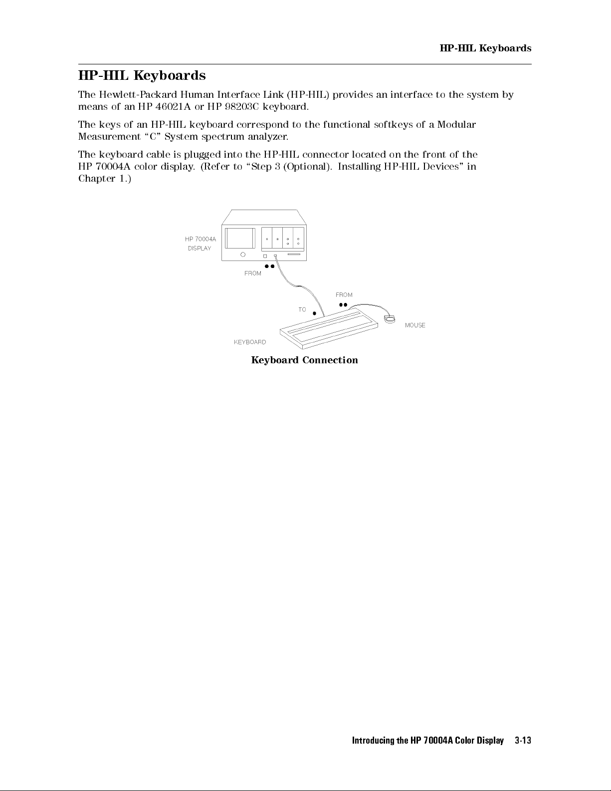
HP-HIL
K
eyboards
HP-HIL
The
Hewlett-P
means
The
keys
of
K
eyboards
ackard
an
HP
46021A
of
an
HP-HIL
Human
or
keyboard
Interface
HP
98203C
Link
keyboard.
correspond
Measurement \C" System spectrum analyzer.
The
keyboard
HP
70004A
Chapter
1.)
cable
color
is
plugged into the HP-HIL connector located on the front of the
display
. (Refer to \Step 3 (Optional). Installing HP-HIL Devices" in
K
eyboard
(HP-HIL)
to
provides
an interface to the system by
the functional softkeys of a Modular
Connection
Introducing the HP 70004A Color Display 3-13
Page 64

HP-HIL
K
eyboards
Functional Keycodes
HP
46021A
Keyboard
This
keyboard
The
function
right-hand
When
4f15
display
Function
the
The
the
through
from top to bottom, respectively.
NNNNNNNNNNNNNN
USER
following
spectrum
has
eight
function
5
keys
softkeys
4
SHIFT
5
4
on the keyboard correspond to the left-hand softkeys on the
f7
key
4
f8
through
4
f1
on
the
display
5
key is pressed at the same time a function key is pressed,
5
on the keyboard, either shifted or not shifted, corresponds to
keys along the top row.
5
on
4
the
f7
keyboard
correspond
from top to bottom, respectively.
to the
softkey on the display.
keys on the HP 46021A keyboard correspond to the indicated
analyzer
functions.
Keyboard Function Key Spectrum Analyzer Function
4
5
Menu
4
Shift User
4
5
System
4
Shift54Reset
4
5
4
Shift
Print
4
5
4
CTRL
4
Break
4
Shift
Shift
5
5
4
Clea
5
5
5
5
5
4
Print
5
r
Line
MENU
USER
DISPLA
I-P
PRINT
PLOT
LOCAL
CLEAR
Y
to
END
HP 98203C
Keyboard
This keyboard has 10 function keys in a cluster.
The function keys
4k15
through
4k75
on the keyboard correspond to the
right-hand softkeys on the display from top to bottom, respectively.
When
4k15
through
the
4
SHIFT
4
k7
5
key
is
pressed
5
on
the
keyboard
at
the
same
correspond
time
a function key is pressed,
to
the
left-hand
softkeys on the
display from top to bottom, respectively.
The softkeys
correspond to the
4k85,4k95
4
USER
,and
5(4k85),4
4
5
on the keyboard, either shifted or not shifted,
k10
5(4k95
MENU
), and
4
DISPLAY
5(4
k10
5
) keys on the
HP 70004A color display.
The following keys on the HP 98203C keyboard correspond to the indicated
spectrum analyzer functions
.
Keyboard Function Key Spectrum Analyzer Function
4
SHIFT54PAUSE
4
SHIFT54ALPHA
4
SHIFT54GRAPHICS
4
SHIFT54CLR->END
4
CLR I/O
5
5
5
5
5
I-P
PRINT
PLOT
CLEAR LINE
LOCAL
After a function is selected, the knob on the HP 98203C keyboard can be used
to scroll through the available parameters.
3-14 Introducing the HP 70004A Color Display
Page 65

Alpha
keys
On
either
selected,
keyboard,
4A5-4Z5,4a5-4z5
N
N
N
N
N
the
TITLE
after
, punctuation,
N
NNNNNNNNNNN
or
4
Ins
N
N
N
N
N
N
NNNNNNNNNNNNNNNNN
COMMAND
5
and
HP-HIL
mode
softkeys
4
5
are used to insert or delete
DEL
K
have
eyboards
been
characters into a title or command.
When these keys are pressed, the response is the same as with the TITLE or
COMMAND mode menu blocks.
A title or command can be typed using the HP-HIL keyboard. Pressing
or
4
5
will terminate the title or command, and the HP 70900A/B local
Enter
oscillator source will respond.
4
Return
5
Introducing the HP 70004A Color Display 3-15
Page 66

Rear-P
anel
Connectors
HP
1
HP-IB
2 MSIB The
3
RGB
70004A
The
IEEE-488
other
display
and
Hewlett-P
Modular System Interface Bus (MSIB)
A
Color
Display
communication
HP-IB
instruments
that
implements
ddress Switches
Rear-P
ackard
anel
Interface
between
,
and
each
HP-IB
.
Connectors
Bus
the
module
(HP-IB)
display
installed
,
is the high-speed
digital bus used by master and slave modules and other
elements for exchanging control information and data.
The
RGB
monitor output provides a red, green, and blue
output,
horizontal
and
with
sync
sweep
400
horizontal lines).
on green (75 impedance, 1 Vpp, 25 kHz
frequency
, 60 Hz vertical sweep frequency,
provides
controllers
in
,
the
RCA
to
available for BNC connections.
3-16 Introducing the HP 70004A Color Display
BNC adapters (HP part number 1250-1853) are
Page 67

Rear-P
anel
Connectors
and
A
ddress
Switches
A display section is an independent element. When you set the HP-IB switch to 0 (OFF), the
HP-IB interface for the
display section only
is turned o. Modules plugged into the display
are unaected and may still talk to each other through HP-IB or communicate over the rear
panel HP-IB connector. The HP-IB switch does not disrupt instrument operation.
MSIB
A
ddress
HP-IB
A
ddress
00000 0
00001 1
00010 2
00011 3
00100
1
The display section's MSIB COLUMN address is factory-preset to 4 and may be changed, but the display's MSIB ROW
1
4
address is permanently set to 0.
HP-IB ON/OFF The HP-IB ON/OFF switch is used to turn on or o the
A1|A5
display's
These
HP-IB
address
without
switches
disrupting
set
the
MSIB column address,
instrument
operation.
which is also the default HP-IB address. Setting the HP-IB
address from the front panel overrides the rear panel
HP-IB address switch setting.
Note that address switches A6|A8 do not exist on the
HP 70004A color display so that the MSIB row address is
always 0.
TALK ONL
Y When you set the T
display can talk on HP-IB without requiring a reply
alk Only switch to 1 (ON), the
. This
accommodates, for example, listen-only plotters.For
normal operation, set switch to 0 (OFF).
SYSTEM CONTROLLER When you set the System Controller switch to 1 (ON) the
display may function as a system controller on HP-IB
during printer or plotter dumps.
Introducing the HP 70004A Color Display 3-17
Page 68

Rear-P
TEST
anel
Connectors
and
A
ddress
Switches
MODE When you set the Test Mode switch to 1 (ON), the display
goes into a special test mode at power-up.For normal
operation, set this to 0 (OFF).
3-18 Introducing the HP 70004A Color Display
Page 69

Operating/Local MSIB Operation
Summary
chapter
you
will learn about:
In
this
Conguring your system and assigning instruments (modules) to dierent
windows.
Changing the color settings and system clock time used by the display.
Printing and plotting display screens.
Saving and retrieving information.
This
chapter
prepares
you for your rst steps in using the HP 70004A color display in a system.
You will learn how to build or stack windows on your display and assign the keyboard or
display or both to an instrument by using various softkey menus. Then, you will learn how to
change display colors and set the system clock. Finally, you'll learn how to produce outputs
on a printer or plotter, and how to save and retrieve information using external mass storage
devices such as HP-IB disk drives and RAM cards.
4
Conguring
Conguring
Conguring
Printing
Selecting
and
and
Miscellaneous
Display
Display
the
Display
Plotting
Saving
User Tasks
Windows
Colors
Clock
:
:
:
to
External
:
:
:
:
:
:
:
:
:::::: ::::::: :::::: ::::::: ::::::: ::::::: :::::: ::::::: :::
:
:
:
:
:
:
:
:::::: ::::::: ::::::: :::::: ::::::: ::::::: :::::: ::::::: ::::::
:
:
:
:
:
:
::::::: :::::: ::::::: ::::::: :::::: ::::::: ::::::: :::::: ::::
:
:
:
:
:::::: ::::::: :::::: ::::::: ::::::: :::::: ::::::: ::::::: ::::::: :::::
Mass
Storage
Devices
:
:
::::::: :::::: ::::::: ::::::: :::::: :
::::::: ::::::: :::::: ::::::: ::::::: :::::: ::::::: ::::::: :::::: ::::::: :
4-2
4-16
4-20
4-22
4-30
4-38
Operating/Local MSIB Operation 4-1
Page 70

Conguring
In
this
section,
keyboard
congured
and
T
o
T
o
T
o
T
o
T
o
or
start
over
build
stack
build
establish
access
your
1,
2
custom
To view column and row addresses in the address map
To assign the display (only) to an instrument
To assign the keyboard (only) to an instrument
you
display
system,
Display
will
learn
or
both
Windows
how
to
you
can
to
build or stack windows on your display and assign the
an
instrument
view
your
.
2, or 4 windows on the display
or 4 windows on the display
sized windows on the display
a
link to an instrument
a window over HP-IB
:::::: ::::::: :::::: ::::::: ::::::: :::::: ::::::: ::::::: :::::
:::::: ::::::: ::::::: :::::: ::::::: ::::::: ::::::: :::::: ::::::: ::
by using various softkey menus. After you have
conguration
and then start using it, or purge it
::::::: ::::::: :::::: ::::::: ::::::: :::::: ::::::: ::::
:::::: ::::::: ::::::: :::::: ::::::: ::::::: :::::: ::::::: :
:::::: ::::::: ::::::: :::::: ::::::: ::::::: :::::: :
::::: ::::::: :::::: ::::::: ::::::: ::::::
::::::::::::::::::::::::::::::::::::::::::::::::
::::::: ::::::: :::::: ::::::: ::::::: :::::: ::::::
To assign both the display and keyboard to an instrument
To set the HP-IB address of a master module
:::::: ::::::: :::::: ::::::: ::::::: :::::: ::::::: ::
To set the HP-IB/MSIB address of the HP 70004A color display
T
o show system congurations
T
o save a system conguration
T
o
recall a system conguration
T
o
purge a window conguration
T
o purge conguration registers
To clear the display
::::::: :::::: ::::::: ::::::: ::::::: :::::: ::::::: ::::::: :::::: ::::::: :::::::
:::::: :::::: ::::::: ::::::: :::::: ::::::: ::::::: :::::: ::::::: :::
:::::: :::::: ::::::: ::::::: :::::: ::::::: ::::::: :::::: ::::::: :::
:::::: ::::::: :::::: ::::::: ::::::: :::::: ::::::: ::::::: :::::: ::
:::::::::::::::::::::::::::::::::::::::::::::::::::::::::::
::::::: ::::::: :::::: ::::::: ::::::: :::::: ::::::: ::::::: :::::: :
:::::: :::::: ::::::: ::::::: :::::: ::
:::::: :::::: ::::::: ::::::: ::
4-3
4-4
4-5
4-6
4-6
4-7
4-8
4-8
4-9
4-9
4-10
4-11
4-12
4-13
4-14
4-14
4-15
4-2 Operating/Local MSIB Operation
Page 71

Conguring
Display
To build 1, 2, or 4 windows on the display
1.
2.
3.
4.
Press
4
DISPLAY
N
NNNNNNNNNNNNNNNNNNNNNNNNNNNNNNNNNNNNNNNNNNN
BUILD 1 WINDOW
Press
N
NNNNNNNNNNNNNNNNNNNNNNNNNNNNNNNNNNNNNNNN
Press
assign window
NNNNNNNNNNNNNNNNNNNNNNNNNNNNNNNNNNN
Press
MSIB COLUMN
NNNNNNNNNNNNNNNNNNNNNNNNNNNNNNNNNNNNNNNNNNNN
5
Config
Display
N
or
.
to assign an instrument to the currently selected window.
NNNNNNNNNNNNNNNNNNNNNNNNNNNNNNNNNNNNNN
build
window
NNNNNNNNNNNNNNNNNNNNNNNNNNNNNNNNNNNNNNNNNNNNNN
BUILD 2 WINDOWS
N
NNNNNNNNNNNNNNNNNNNNNNNNNNNNNNNNNNNNNNNNNNNNNN
BUILD 4 WINDOWS
or
If you have more than one window built, you can also assign an instrument to a dierent
window by selecting a number between 1 and 4 from the keypad or HP-HIL keyboard and
pressing
your
The
2
windows
NNNNNNNNNNNNNNNNN
ENTER
selection
window selected, if currently dened, is highlighted with a green border; if you built
. (If you make an error, press
with
the
corrected
entry if necessary.)
NNNNNNNNNNNNNNNNNNNNNNNNNNNNNNNNNNNNNNNNNNNNNNN
(using
BUILD
2
WINDOWS
)
and
tried
4 5
to return to the previous menu. Repeat
to
assign
an instrument to window 3
or window 4, the assignment would not be accepted because only windows 1 and 2 are
available for assignment.
Windows
5. Rotate the front panel knob (or use the
445or455
keys, or the numeric keypad) to enter the
column number of the instrument you are interested in assigning to the current window.
Press
If
you
NNNNNNNNNNNNNNNNNNNNNNN
EXECUTE
selected
.
N
N
N
N
N
N
N
N
N
N
N
N
N
NNNNNNNNNNNNNNNNNNNNNNNNNNNNNNNNNN
BUILD
2
WINDOWS
or
N
N
N
N
N
N
N
N
N
N
N
N
N
NNNNNNNNNNNNNNNNNNNNNNNNNNNNNNNNNN
BUILD
4
WINDOWS
,
repeat
steps
3
through
6 above to
6.
7.
assign instruments to each of the remaining windows.
A window is a user-dened portion of the HP 70004A color display that is set aside for a
single instrument (master) to display information.
Each instrument can only be assigned to one window at a time because each instrument can
establish
to
be
automatically with the use of
only
one
reassigned
display
to
a
link
with
the HP 70004A color display; in order for an instrument
new
window, all previous display links must rst be broken; this is done
NNNNNNNNNNNNNNNNNNNNNNNNNNNNNNNNNNNNNNNNN
assign window
.
If you are having problems nding an instrument to assign to a window, refer to the section
\To view column and row addresses in the address map".
Note
In both
build
and
stack
functions, if windows remain unlled, the display will
search the address map for other instruments on row 0 to ll the windows.
The windows are lled in order (1{4) and the modules are assigned in order
of address (0{30). There is an exception to this rule. If a window has been
assigned to a module and that module has been removed from the system,
no attempt will be made to nd another module for that window unless that
window has rst been purged using
NNNNNNNNNNNNNNNNNNNNNNNNNNNNNNNNNNNNNN
purge window
NNNNNNNNNNNNNNNNNNNNNNNNNNNNN
or
PURGE ALL
.
Operating/Local MSIB Operation 4-3
Page 72

Conguring
Display
Windows
To stack 2 or 4 windows on the display
1.
2.
3.
4.
Press
4
DISPLAY
N
NNNNNNNNNNNNNNNNNNNNNNNNNNNNNNNNNNNNNNNNNNNNNN
STACK 2 WINDOWS
Press
N
Press
NNNNNNNNNNNNNNNNNNNNNNNNNNNNNNNNNNNNNNNN
assign window
NNNNNNNNNNNNNNNNNNNNNNNNNNNNNNNNNNN
Press
MSIB COLUMN
NNNNNNNNNNNNNNNNNNNNNNNNNNNNNNNNNNNNNNNNNNNN
5
Config
Display
or
.
to assign an instrument to the currently selected window.
NNNNNNNNNNNNNNNNNNNNNNNNNNNNNNNNNNNNNN
build
N
NNNNNNNNNNNNNNNNNNNNNNNNNNNNNNNNNNNNNNNNNNNNNN
window
STACK 4 WINDOWS
.
You can also assign an instrument to a dierent window by selecting a number between 1
and 4 from the keypad or HP-HIL keyboard and pressing
press
4 5
to return to the previous menu. Repeat your selection with the corrected entry if
NNNNNNNNNNNNNNNNN
ENTER
. (If you make an error,
necessary.)
The window selected, if currently dened, is highlighted with a green border; if you built
2 windows (using
or
window
4,
NNNNNNNNNNNNNNNNNNNNNNNNNNNNNNNNNNNNNNNNNNNNNNN
STACK 2 WINDOWS
) and tried to assign an instrument to window 3
the assignment would not be accepted because only windows 1 and 2 are
available for assignment.
5. Rotate the front panel knob (or use the
445or455
keys, or the numeric keypad) to enter the
column number of the instrument you are interested in assigning to the current window.
Press
Repeat
NNNNNNNNNNNNNNNNNNNNNNN
EXECUTE
steps
3 through 6 above to assign instruments to each of the remaining windows.
.
6.
7.
A window is a user-dened portion of the HP 70004A color display that is set aside for a
single instrument (master) to display information.
Each instrument can only be assigned to one window at a time because each instrument can
establish
to
be
automatically with the use of
If
you
\T
o
only
reassigned
are
having
view
column
one
display
to
a
new
link
with
the
window
,
all
N
N
N
NNNNNNNNNNNNNNNNNNNNNNNNNNNNNNNNNNNNNN
assign window
HP
70004A
previous
color
display
. In order for an instrument
display links must rst be broken; this is done
.
problems nding an instrument to assign to a window, refer to the section
and row addresses in the address map".
In
both
Note
build
search the address map for other instruments on row 0 to ll the windows.
The windows are lled in order (1{4) and the modules are assigned in order
of address (0{30). There
assigned to a module and that module has been removed from the system,
no attempt will be made to nd another module for that window unless that
window has rst been purged using
4-4 Operating/Local MSIB Operation
and
stack
functions, if windows remain unlled, the display will
is an exception to this rule. If a window has been
NNNNNNNNNNNNNNNNNNNNNNNNNNNNNNNNNNNNNN
purge window
NNNNNNNNNNNNNNNNNNNNNNNNNNNNN
or
PURGE ALL
.
Page 73

To build custom sized windows on the display
1.
2.
Press
Press
NNNNNNNNNNNNNNNNNNNNNNNNNNNNNNNNNNNNNNNNNNNN
5
4
DISPLAY
N
NNNNNNNNNNNNNNNNNNNNNNNNNNNNNNNNNNNNN
DISPLAY
build window
PRESET
N
NNNNNNNNNNNNNNNNNNNNNNNNNNNNNNNNNNNNNNNNNNN
custom windows
NNNNNNNNNNNNNNNNNNNNNNNNNNNNNNNNNNNNNNNNNNNN
Config
Display
N
NNNNNNNNNNNNNNNNNNNNNNNNNNNNNNNNNNNNNNNN
SELECT WINDOW
.
Conguring
.
Display
Windows
3. Designate the number of the window that you would like to build by selecting a number
between 1 and 4 from the keypad or HP-HIL keyboard and pressing
window being built is window 1. (If you make an error,press
4 5
NNNNNNNNNNNNNNNNN
ENTER
; the default
to return to the previous
menu. Repeat your selection with the corrected entry if necessary.)
4.
NNNNNNNNNNNNNNNNNNNNNNNNNNNNNNNNNNNNNNNNNNNNNNN
Press
DEFAULT CORNERS
NNNNNNNNNNNNNNNNNNNNNNNNNNNNN
SET Y-min
.
5. Using the display knob, select a position for the bottom of your custom window.
F
or
example
of the window in the center screen and press
,
to
create
a
custom
window over the top half of the display, place the bottom
NNNNNNNNNNNNNNNNNNNNNNN
EXECUTE
.(You can specify the approximate
center of the screen by entering 191 through the numeric keypad.)
N
N
N
N
N
N
N
6.
7.
Press
Press
4 5
N
N
MSIB
NNNNNNNNNNNNNNNNNNNNNNNNNNNNNNNNNN
assign window
N
N
N
N
N
N
N
N
NNNNNNNNNNNNNNNNNNNNNNNNN
COLUMN
to
.
assign
an
instrument
to the currently selected window.
If you have more than one window built, you can also assign an instrument to a dierent
window by selecting a number between 1 and 4 from the keypad or HP-HIL keyboard and
pressing
N
N
N
N
N
N
NNNNNNNNNNN
ENTER
.
(If you make an error, press
4
5
to
return to the previous menu. Repeat
your selection with the corrected entry if necessary.) The window selected, if currently
dened, is highlighted with a green border. If you built only 1 custom window and tried to
assign an instrument to window 2, 3, or 4, the assignment would not be accepted because
only window 1 is available for assignment; you would have to build additional windows.
8.
Rotate
the
window
the
column
.
front
number
panel
of
knob
the
instrument
(or
use
the
4
you
4
5
or
4
are
interested
5
5
keys
,
or
the
numeric
keypad)
in assigning to the current
to
enter
NNNNNNNNNNNNNNNNNNNNNNN
9.
Press
EXECUTE
.
10. Repeat steps 2 through 9 above to build additional custom windows.
Up to four custom dened windows can be built and assigns instruments in each
conguration.
A window is a user-dened portion of the screen that is set aside for a single instrument to
display information. Allowable custom window dimensions are from 0 to 383 along the y-axis
and 0 to 1023 along the x-axis.
The window being dened has a green border
default window (selected by
NNNNNNNNNNNNNNNNNNNNNNNNNNNNNNNNNNNNNNNNNNNNNNN
DEFAULT CORNERS
, the old window has a gray border, and the
) has a red border
.
Operating/Local MSIB Operation 4-5
Page 74

Conguring
Display
Windows
To establish a link to an instrument
1.
Press
4
DISPLAY
NNNNNNNNNNNNNNNNNNNNNNNNNNNNNNNN
5
NEXT
INSTR
.
If the display does not have a link to an instrument, it will look for the instrument with the
lowest column address on the MSIB and allocate the entire screen and the 14 softkeys to
that instrument.
If a link already exists, the display will select the instrument with the next higher address
(following the sequence.... 28, 29, 30, 0, 1, 2.... ).
2.
Continue to press the
445
NNNNNNNNNNNNNNNNNNNNNNNNNNNNNNNN
(or
NEXT INSTR
again) or
455
keys to select the instrument with
the next higher or next lower address.
3. Press
Under
4
USER
4
USER
5or4
5
, you may have softkeys for DLPs and under
MENU
5
and use the appropriate softkeys.
4
MENU
5
, you may have softkeys
that are specic to the module that you selected. For information on using softkeys, refer to
the user guide for your specic module.
The
information
specic
between
instrument
the
displayed, once the display is given to an instrument, depends on the
selected.
display
and
the
N
N
N
N
N
N
N
N
N
NEXT
Since
instrument,
N
N
N
N
N
NNNNNNNNNNNNNNNNNN
INSTR
most
only
establishes
instrument
settings
communication
are not aected when an
links
instrument is selected; however, any previously dened display windows are erased.
T
o
access
1.
Press
2.
Press
3. Select a window by entering a number between 1 and 4 from the keypad or HP-HIL
keyboard and pressing
a
4
DISPLA
N
N
N
N
N
N
N
N
N
N
N
N
N
NNNNNNNNNNNNNNNNNNNNNNNNNNNN
assign
window
N
N
N
N
NNNNNNNNNNNNNNNNNNNNNNNNNNNNNNN
Address Map
5
Y
window
over
.
NNNNNNNNNNNNNNNNN
ENTER
HP-IB
.
. (If you make an error, press
4 5
to return to the previous
menu. Repeat your selection with the corrected entry if necessary.)
4.
Press
N
N
N
HP-IB
NNNNNNNNNNNNNN
N
N
N
NNNNNNNNNNNNNNNNNNNN
EXECUTE
.
NNNNNNNNNNNNNNNNNNNNNNNNNNNNNNNNNNN
The window will have the HP-IB address of the display.(See
Address Map
to determine
the HP-IB address of the display.)
Only one display window, at a given time, can be assigned to HP-IB.
HP-IB can also operate without an explicitly dened window
, since it automatically receives
window 5 at power-up; if not assigned one, no HP-IB window appears in
4-6 Operating/Local MSIB Operation
NNNNNNNNNNNNNNNNNNNNNNNNNNNNNNNNNNN
SHOW CONFIG
.
Page 75

Conguring
Display
Windows
To view column and row addresses in the address map
1.
Press
4
DISPLAY
NNNNNNNNNNNNNNNNNNNNNNNNNNNNNNNNNNN
5
Address
NNNNNNNNNNNNNNNNNNNNNNNNNNNNNNNNNNNNNNNNN
ADJUST
Map
COLUMN
.
2. Turn the knob until the rectangle encompasses an instrument on ROW 0 or until it is
beneath an instrument in the same column.
NNNNNNNNNNNNNNNNNNNNNNNNNNNNNNNN
To select modules from the vertical columns, use
place
the
The
rectangle
N
N
N
N
N
N
N
NNNNNNNNNNNNNNNNNNNNNNNNNNNNNNNNNN
ADJUST
COLUMN
around
and
the
module of interest.
N
N
N
N
N
N
N
NNNNNNNNNNNNNNNNNNNNNNNNN
ADJUST
ROW
softkeys
within the address map; these softkeys accept data entry from the display knob, the
455
keys, and the numeric keypad.
ADJUST ROW
are
used to move the highlighted rectangle
along with
445
and
455
445
As the rectangle is moved through the address map and used to select a module,the
corresponding module's front panel, green-active, LED will turn on. The HP 70004A color
display represents its green-active LED as a greenAin the system state area; the system
state area is located in the upper-left corner of the display screen. The green-active LED on
modules
to
locations
and the green A in the HP 70004A color display's system state area enables you
correlate
the specic HP 70000 Series modular measurement system modules to their
in
the address map.
to
and
Note
The HP 70004A color display's MSIB COLUMN address is factory-preset to 4
and may be changed, but the display's MSIB ROW address is permanently set to
0. When used with other factory-preset modules, you may not have to change
the
preset
addressing
unless
two
or
more
of
the
same
model
modules are used.
Operating/Local MSIB Operation 4-7
Page 76
Conguring
Display
Windows
To assign the display (only) to an instrument
1.
Press
4
DISPLAY
NNNNNNNNNNNNNNNNNNNNNNNNNNNNNNNNNNN
5
Address
NNNNNNNNNNNNNNNNNNNNNNNNNNNNNNNNNNNNNNNNN
ADJUST
Map
COLUMN
.
2. Turn the knob until the rectangle encompasses an instrument on ROW 0.
N
N
3.
Press the
The
trace
4.
T
o
assign
instrument
is
selected.
N
N
N
N
N
NNNNNNNNNNNNNNNNNNNNNNNNNNNNNNNNNNNNNNN
ASSIGN
NNNNNNNNNNNNNNNNNNNNNNNNNNNNNNNNNNNNNNNNNN
ASSIGN DISPLAY
screen
will
information,
the
display
selected
DISPLAY
be
immediately
the
information
back
from
assigns
softkey.
allocated
to
an instrument, either repeat this procedure with the original
the address map or press
will
to
that
be
displayed.
module. If the module is ready to put out
5
until
the
4
NEXT
INSTR
desired instrument
the whole screen to a particular instrument, even though the
keyboard may be assigned elsewhere.
This allows the user to view the trace output from one instrument on the display, while
controlling a dierent instrument with the keyboard. The two display resources,the
keyboard
T
o
assign
1.
Press
and the display screen, can be allocated separately.
the
4
DISPLA
keyboard
N
N
N
N
N
NNNNNNNNNNNNNNNNNNNNNNNNNNNNNN
Address
5
Y
(only)
Map
to
an instrument
N
N
N
N
N
NNNNNNNNNNNNNNNNNNNNNNNNNNNNNNNNNNNN
ADJUST
COLUMN
.
2.
Turn
the
knob
until
the
rectangle encompasses an instrument on ROW 0.
3.
NNNNNNNNNNNNNNNNNNNNNNNNNNNNNNNNNNNNNN
Press
ASSIGN
The
keyboard
KEYBD
4
MENU
5
.
will be immediately allocated to that module.
4. To assign the keyboard back to an instrument, either repeat this procedure with the original
instrument selected from the address map or press
4
NEXT
INSTR
5
until the desired instrument
is selected.
NNNNNNNNNNNNNNNNNNNNNNNNNNNNNNNNNNNNNN
The
ASSIGN KEYBD
softkey is used to allocate the keyboard to a specic module.The
keyboard can then be used to control the instrument settings.
NNNNNNNNNNNNNNNNNNNNNNNNNNNNNNNNNNNNNN
The keyboard and the screen can be allocated separately.
ASSIGN KEYBD
links the keyboard
with an instrument, but does not necessarily display any trace data from that instrument.
Because of this, the softkeys may not correspond to the instrument display shown.
Only a master module such as the HP 70900B local oscillator source can receive the
keyboard. Attempts to allocate the keyboard to slave modules will result in an error
Use the
once they are assigned to windows
4
INSTR
5
key as the primary way of transferring the keyboard between instruments
5
. When the
4
INSTR
key is pressed, the display assigns
.
colored borders to the currently dened windows. Near each window a softkey containing
the rst seven characters in the module's model number and address (row and column) are
displayed in inverse video in the same color as the border. If a labeled softkey is pressed, the
keyboard is oered to that window's instrument. If the instrument accepts the keyboard it
will put up its menu keys, as though the
4
MENU
5
key had been pressed.
4-8 Operating/Local MSIB Operation
Page 77

Conguring
Display
To assign both the display and keyboard to an instrument
1.
Press
4
DISPLAY
NNNNNNNNNNNNNNNNNNNNNNNNNNNNNNNNNNN
5
Address
NNNNNNNNNNNNNNNNNNNNNNNNNNNNNNNNNNNNNNNNN
ADJUST
Map
COLUMN
.
2. Turn the knob until the rectangle encompasses an instrument on ROW 0.
N
N
3.
Press
NNNNNNNNNNNNNNNNNNNNNNNNNNNNNNNNN
ASSIGN BOTH
4
MENU
5
.
NNNNNNNNNNNNNNNNNNNNNNNNNNNNNNNNNNN
ASSIGN BOTH
establishes contact between the display and a specic instrument, and then
allocates the screen and keys to the module currently highlighted by the rectangle in the
address map.
N
N
NNNNNNNNNNNNNNNNNNNNNNNNNNNNNNNNN
ASSIGN BOTH
NNNNNNNNNNNNNNNNNNNNNNNNNNNNNNNNNNN
ASSIGN BOTH
instrument
Both
on
softkeys
diers from
requires that a particular module be specied while
its
own
,
however
N
N
NNNNNNNNNNNNNNNNNNNNNNNNNNNNNN
NEXT INSTR
:
NNNNNNNNNNNNNNNNNNNNNNNNNNNNNNNN
NEXT INSTR
by
scanning ROW 0 of the address map until it nds a master module.
,
disconnect any links between the display and any other instruments,
selects an
and both destroy any existing windows in the display.
To set the HP-IB address of a master module
N
1.
Press
4
DISPLA
N
N
N
N
Address
5
Y
N
N
N
N
N
N
NNNNNNNNNNNNNNNNNNNNNNNNN
Map
N
N
N
N
N
N
N
N
N
NNNNNNNNNNNNNNNNNNNNNNNNNNNNNNN
ADJUST
COLUMN
.
Windows
2.
Turn
the
knob
until
the
rectangle
set
the
HP-IB
3.
Press
the
4.
Enter the new address using the keypad. (For example, select
HP-IB
address
N
N
N
N
N
N
N
N
N
N
N
HP-IB
address
N
N
N
N
NNNNNNNNNNNNNNNNNNNNNNNNNN
ADDRSET
of
the
on.
module
encompasses
should
immediately
an
instrument
change
to
on
ROW 0 that you want to
NNNNNNNNNNNNNNNNN
425,405
,and
ENTER
20.)
.The
NNNNNNNNNNNNNNNNNNNNNNNNNNNNNNNNNNNNNNNNN
The
HP-IB ADDRSET
softkey changes the HP-IB address of any instrument currently on
HP-IB if that instrument will permit it.
All modules that have an HP-IB address must be master modules and must be located on
ROW 0; slave modules cannot have HP-IB addresses.
Some HP 70000 Series modular measurement system elements show an HP-IB address on
the address map even though the element is disabled (by the HP-IB enable switch) and
cannot communicate on HP-IB. Modules show that they are disabled by replacing their HP-IB
address with the wordNOin the address map; they show
HP-IB enable switch is in the OFF position. (F
switch for a particular module
, refer to the installation and verication manual for that
or information on setting the HP-IB enable
HP-IB NO
which means that their
module.) The HP-IB enable switch for the HP 70004A color display is located on the rear
panel. For information on setting the address switches of the HP 70004A color display, refer
to \Step 5. Setting the MSIB and HP-IB Address" in Chapter 1.
Upon power-up, the HP-IB addressing is handled dierently by dierent elements.The
display can be congured to have a power-up HP-IB address of either the MSIB column
address or the most recent HP-IB address given to the display with the
NNNNNNNNNNNNNNNNNNNNNNNNNNNNNNNNNNNNNNNNN
HP-IB ADDRSET
key.
Operating/Local MSIB Operation 4-9
Page 78
Conguring
Display
Windows
To set the HP-IB/MSIB address of the HP 70004A color display
1.
Press
4
DISPLAY
NNNNNNNNNNNNNNNNNNNNNNNNNNNNNNNNNNN
5
Address
NNNNNNNNNNNNNNNNNNNNNNNNNNNNNNNNNNNNNNNNN
ADJUST
Map
COLUMN
.
2. Turn the knob so the rectangle stops on the module that you want to set the HP-IB address
on; in this example, select the HP 70004A color display.
N
N
N
N
N
N
3.
Press
NNNNNNNNNNNNNNNNNNNNNNNNNNNNNNNNNNN
HP-IB
the
ADDRSET
4. Enter the new address using the keypad.
NNNNNNNNNNNNNNNN
(For example, select
immediately
change
425,405
to
20.)
,and
N
ENTER
. The HP-IB address of the module should
The HP 70004A color display's MSIB COLUMN address is factory-preset to 4 and may be
changed, but the display's MSIB ROW address is permanently set to 0.
Setting the MSIB COLUMN address of the display, species both the MSIB address and the
HP-IB address of the HP 70004A color display.
F
or
information on setting the address switches of the HP 70004A color display,referto
\Step
5.
Setting
the
MSIB and HP-IB Address" in Chapter 1.
4-10 Operating/Local MSIB Operation
Page 79

To show system congurations
1.
Press
4
DISPLAY
NNNNNNNNNNNNNNNNNNNNNNNNNNNNNNNNNNNNNNNNNNNN
5
Config
Display
NNNNNNNNNNNNNNNNNNNNNNNNNNNNNNNNNNN
SHOW
CONFIG
Conguring
Display
Windows
.
2. In addition to the current conguration that is shown, use the
Conguration Registers 1 through 4. These other conguration registers can be loaded with
information using
N
N
NNNNNNNNNNNNNNNNNNNNNNNNNNNNNNNNN
SAVE CONFIG
. (Refer to the section \To save a system conguration".)
445
and
455
keys to view
The display has six resources that it can assign to any of several HP 70000 Series elements:
these resources consist of a screen composed of up to four windows, plus a fth window
reserved for a controller on HP-IB, and one keyboard. The fth window is invisible; it does
not show up when using
NNNNNNNNNNNNNNNNNNNNNNNNNNNNNNNNNNN
SHOW CONFIG
.
NNNNNNNNNNNNNNNNNNNNNNNNNNNNNNNNNNN
SHOW CONFIG
not only brings up the current conguration of the display, but also
can show four other complete display congurations. These congurations reside in
continuous-memory registers, so they will be recalled even if the power had been turned o.
NNNNNNNNNNNNNNNNNNNNNNNNNNNNNNNNNNN
SHOW CONFIG
each
window
whether
dened
if
a
window
the
instrument
the
abbreviated
abbreviated
following
below
Up
to
four
Current
displays the following information:
number
or
not
a
in
the
conguration
is
dened,
name
the
the
abbreviated
windows
Conguration"
(windows
window
is
then
that
the
name
of
refers
abbreviated
name
can
be dened in each conguration. While looking at the \Example
shown
1
dened
being
the
following
keyboard
the
instrument
to
the
instrument
name
are
below
through
viewed,
is
the X and Y dimensions of each dened window
4)
in
the
is
assigned
conguration
it
will
display
is
also
displayed:
to
that
is
assigned
being
the
to
viewed;
word:
each
if
a
undefined
window;
window
the
is not
that can write to a given window.
the MSIB ROW and COLUMN address
,
notice that only windows one and two are dened,
while windows three and four are undened. In addition, you can also determine that
the keyboard is assigned to window one, the HP 70900B local oscillator source is assigned
to window one which is at MSIB address ROW 0 and COLUMN 18, and the HP 70700A
digitizer is assigned to window two which is at MSIB address ROW 0 and COLUMN 7.
Example of a Current Conguration
Operating/Local MSIB Operation 4-11
Page 80

Conguring
Display
Windows
To save a system conguration
1.
Press
4
DISPLAY
2.
Select a number between 1 and 4 from the keypad or HP-HIL keyboard and press
(If you make an error, press
NNNNNNNNNNNNNNNNNNNNNNNNNNNNNNNNNNNNNNNNNNNN
5
Config
Display
.
4 5
to return to the previous menu. Repeat your selection with
the corrected entry if necessary.)
N
N
N
3.
Press
This
to
battery-backed
NNNNNNNNNNNNNNNNNNNNNNNNNNNNNNNN
SAVE
saves
four
windows
CONFIG
the
current
.
conguration
per
conguration).
RAM
if
the
power
in
The
is
turned
one
current
of
o.
the
four conguration registers (with up
conguration
will also be retained in
N
NNNNNNNNNNNNNNNN
ENTER
.
4-12 Operating/Local MSIB Operation
Page 81

Conguring
To recall a system conguration
1.
Press
4
DISPLAY
2.
Select a number between 1 and 4 from the keypad or HP-HIL keyboard and press
(If you make an error, press
NNNNNNNNNNNNNNNNNNNNNNNNNNNNNNNNNNNNNNNNNNNN
5
Config
Display
.
4 5
to return to the previous menu. Repeat your selection with
the corrected entry if necessary.)
N
N
N
3.
Press
This
registers
NNNNNNNNNNNNNNNNNNNNNNNNNNNNNNNNNNNNNN
RECALL
recalls
a
(with
CONFIG
previously
up
to
.
four
stored
windows
conguration
per
conguration).
that
is
saved
in one of the four conguration
Display
Windows
N
NNNNNNNNNNNNNNNN
ENTER
.
Example
NNNNNNNNNNNNNNNNNNNNNNNNNNNNNNNNNNN
SAVE
using
CONFIG
NNNNNNNNNNNNNNNNNNNNNNNNNNNNNNNNNNNNNNNNN
RECALL
and
CONFIG
:
In this example, you save the current conguration in a conguration register, select a
new instrument, use the new instrument to perform a task, and then return to the saved
conguration.
1. Save the current conguration in a conguration register.
a.
Press
4
DISPLAY
b. Select a number between 1 and 4 from the keypad or HP-HIL keyboard and press
N
N
N
N
N
N
NNNNNNNNNNN
ENTER
.
(If you make an error, press
NNNNNNNNNNNNNNNNNNNNNNNNNNNNNNNNNNNNNNNNNNNN
5
Config Display
.
5
to
4
return to the previous menu. Repeat your
selection with the corrected entry if necessary.)
N
N
N
N
N
N
N
N
N
N
N
c.
2.
Press
Continue
Press
4
DISPLAY
SAVE
to
press
NNNNNNNNNNNNNNNNNNNNNNNN
5
CONFIG
.
NNNNNNNNNNNNNNNNNNNNNNNNNNNNNNNN
NEXT INSTR
5
the
(or
4
4
.
N
N
N
N
N
N
N
N
N
NEXT
N
N
N
N
NNNNNNNNNNNNNNNNNNN
INSTR
again)
and
5
keys
to
4
5
select
the
instrument
with the next higher or next lower address until you have selected a desired instrument.
3. Press
4
USER
5or4
MENU
5
and use the appropriate softkeys for the instrument you selected.
4. When nished with the selected instrument, return to the previously saved conguration.
a.
Press
4
DISPLAY
b. Select a number between 1 and 4 from the keypad or HP-HIL keyboard and press
NNNNNNNNNNNNNNNNN
ENTER
. (If you make an error, press
NNNNNNNNNNNNNNNNNNNNNNNNNNNNNNNNNNNNNNNNNNNN
5
Config
Display
.
4 5
to return to the previous menu. Repeat your
selection with the corrected entry if necessary.)
c.
NNNNNNNNNNNNNNNNNNNNNNNNNNNNNNNNNNNNNNNNN
Press
RECALL CONFIG
.
Your previously saved conguration should be restored to the state that it was prior to
performing step 2 of this example
.
Operating/Local MSIB Operation 4-13
Page 82

Conguring
Display
Windows
To purge a window conguration
1.
Press
2.
Press
and press
4 5
NNNNNNNNNNNNNNNNNNNNNNNNNNNNNNNNNNNNNNNNNNNN
5
4
DISPLAY
N
NNNNNNNNNNNNNNNNNNNNNN
EXECUTE
Config
or select a number between 1 and 4 from the keypad or HP-HIL keyboard
NNNNNNNNNNNNNNNNN
ENTER
Display
to specify a particular window to be purged. (If you make an error, press
to return to the previous menu.) A green border outlines the selected window that is to
NNNNNNNNNNNNNNNNNNNNNNNNNNNNNNNNNNNNNN
purge
be purged.
NNNNNNNNNNNNNNNNNNNNNNNNNNNNN
You can also press
PURGE ALL
to purge the stored information from all four windows at
once.
window
.
Note that
through
PURGE ALL
does not purge information that is stored in Conguration Register 1
4 all at once, it only purges the information for windows 1 through 4 that are in
the current conguration register that is selected; each of the four conguration register
(Conguration Register 1 through 4) must be specically selected. (Refer to \To purge
conguration registers".)
NNNNNNNNNNNNNNNNNNNNNNNNNNNNN
T
o
purge
1.
Press
2.
Select
N
N
N
N
N
N
N
ENTER
(Conguration
3.
Press
4.
Press
keyboard and press
conguration. (If you make an error, press
conguration
4
DISPLA
Y
a
number
N
N
N
N
N
N
NNNN
.
The
NNNNNNNNNNNNNNNNNNNNNNNNNNNNNNNNNNNNN
N
purge
N
N
N
N
N
N
N
N
N
NNNNNNNNNNNNNN
EXECUTE
N
N
N
N
N
N
N
N
N
N
Config
5
between
number
Register
window
or
select
registers
N
NNNNNNNNNNNNNNNNNNNNNNNNNNNNNNNNN
Display
1
and
that
is
selected
1
,
2,
3,
.
a
N
NNNNNNNNNNNNNN
number
to specify a particular window to be purged from the selected
N
N
ENTER
N
N
N
N
N
N
N
N
N
N
N
NNNNNNNNNNNNNNNNNNNNNNNNNNNNNN
4
or
RECALL
from
4)
CONFIG
the
keypad
designates
.
or HP-HIL keyboard and press
the
desired conguration register
from which you will be purging information.
between 1 and 4 from the keypad or HP-HIL
4 5
to return to the previous menu.) A green
border outlines the selected window that is to be purged.
NNNNNNNNNNNNNNNNNNNNNNNNNNNNN
You can also press
PURGE ALL
to purge the stored information from all four windows at
once.
Note that
PURGE ALL
does not purge information that is stored in Conguration Register 1
through 4 all at once, it only purges the information that is in a selected conguration
register; each conguration register must be specically selected with the above process
NNNNNNNNNNNNNNNNNNNNNNNNNNNNN
N
To reestablish a display link, press either
NNNNNNNNNNNNNNNNNNNNNNNNNNNN
NEXT INST
(this causes ROW 0 to be scanned for
master modules) or create a new window link using one of the following procedures:
To build 1, 2, or 4 windows on the display
To stack 2 or 4 windows on the display
To build custom sized windows on the display
4-14 Operating/Local MSIB Operation
.
Page 83

Conguring
To clear the display
1.
Press
4
DISPLAY
This key sequence clears the display screen, all errors, the HP-IB output buer, and assigns
the entire display screen to the last instrument controlled by the keyboard. A display
preset is dierent from an instrument preset. An instrument preset would place all of an
instruments settings to their default (preset) value and would not aect the conguration of
the display.
NNNNNNNNNNNNNNNNNNNNNNNNNNNNNNNNNNNNNNNNNNNN
5
DISPLAY
PRESET
.
Display
Windows
Operating/Local MSIB Operation 4-15
Page 84

Conguring
Display
Colors
Display
order
colors
to
have
suit
environmental
been
preset
needs
with
a
,
individual
set
of default colors which you may choose to change in
preferences
, or to accommodate color-decient
vision.
The display's default colors have been chosen to maximize your ability to comfortably discern
the
dierence
provide
The
HP
70004A
selectable
To customize display colors
To set the display color to monochrome
To change the monochrome display to dierent shades of green
To change the special color elements
To save custom display colors
To recall custom display colors
T
o return to default display colors
T
o adjust the brightness of the display
a
suitable
from
between
color
a
on-screen
contrast
that is easy to view for long periods of time.
display can display text and graphics in up to 16 simultaneous colors,
palette of 4096 colors.
::::: ::::::: ::::::: :::::: ::::::: ::::::: :::::: ::::::: ::::::: :::::: :
colors.We recommend these colors for normal use. They
::::::::::::::::::::::::::::::::::::::::::::::::::::
:::::: ::::::: :::::: ::::::: :
:::::: ::::::: ::::::: ::::::: :::::: ::::::: ::::::: :::::: ::
::::: ::::::: :::::: ::::::: ::::::: :::::: ::::::: ::::::: ::::::: ::::
::::: ::::::: ::::::: :::::: ::::::: ::::::: :::::: ::::::: ::::::: :::
::::::::::::::::::::::::::::::::::::::::::::::::::::::::::
:::::: :::::: ::::::: ::::::: ::::::: :::::: ::::::: ::::::: :
4-17
4-17
4-18
4-18
4-18
4-19
4-19
4-19
4-16 Operating/Local MSIB Operation
Page 85

To customize display colors
The following steps will change the background element color.
1.
2.
Press
Press
4
DISPLAY
N
NNNNNNNNNNNNNNNNNNNNNNNNNNNNNNN
5
Adjust Color
BACKGROUND
NNNNNNNNNNNNNNNNNNNNNNNNNNNNNNNNNNNNNN
and rotate the knob clockwise and counter-clockwise; you should notice
NNNNNNNNNNNNNNNNNNNNNNNNNNNNNNNNNNN
edit colors
.
that the hue changes.
3.
4.
5.
6.
NNNNNNNNNNN
Press
RGB
NNNNNNNNNNNNNNNNN
Press
GREEN
N
N
N
N
N
BLUE
Press
Press the
.
NNNNNNNNN
NNNNNNNNNNN
HSL
and use the
and
use
the
4
445
4
5
and
and
455
keys to change the color.
5
keys
4
5
to
change the color.
softkey and rotate the RPG in either direction.
N
T
o
Note
return to the default color settings, press
N
N
N
NNNNNNNNNN
UNDO
Conguring
.
Display
Colors
N
N
NNNNNNNNNNNNNNNNNNNNNNNNNNNNNN
The
BACKGROUND
The
instrument
that
those cases when an instrument does not generate key labels,
will
appear
assigned
inverse
to
video
on
that
block.
the
N
N
NNNNNNNNNNNNNNNNNNNNNNNNNNNNNN
and
KEY LABELS
owns
menu.
the
Each
softkeys always appear in the
display's
keyboard
may
NNNNNNNNNNNNNNNNNNNNNNNNNNNNNNNNNNN
edit
key
in
the
colors
generate
menu
N
N
NNNNNNNNNNNNNNNNNNNNNNNNNNNNNNNNN
edit colors
all
other
NNNNNNNNNNNNNNNNNNNNNNN
COLOR 1
reects
key
through
the
element
menu.
labels
NNNNNNNNNNNNNNNNNNNNNNNNNN
COLOR 10
.In
color
key. Keys whose associated colors are very dim appear surrounded by an
To set the display color to monochrome
N
1.
Press
4
DISPLAY
N
N
N
N
N
N
Adjust
5
N
N
N
N
NNNNNNNNNNNNNNNNNNNNNNNNNNNN
Color
N
N
N
N
N
N
N
N
N
NNNNNNNNNNNNNNNNNNNNNN
MONOCHROME
.
NNNNNNNNNNNNNNNNNNNNNNNNNNNNNNNN
MONOCHROME
The
monochrome display uses dierent shades of green; up to ten dierent shades can
be
specied. This is especially useful for driving external monochrome monitors from
the
green video output available through the rear panel. For a listing of the default
sets the display screen to green monochrome.
monochrome colors, refer to Table 5-5 and for information on driving external monitors, refer
to \Understanding RGB Video Outputs and Their Use
" in Chapter 9.
Operating/Local MSIB Operation 4-17
Page 86

Conguring
Display
Colors
To change the monochrome display to dierent shades of green
1.
2.
3.
Press
Press
Press
NNNNNNNNNNNNNNNNNNNNNNNNNNNNNNNNNNNNNN
5
4
DISPLAY
N
NNNNNNNNNNNNNNNNNNNNNNNNNNNNNNNNNN
Adjust
edit colors
N
NNNNNNNNNNNNNNNNNNNNNN
HSL/RGB
NNNNNNNNNNNNNNNNN
GREEN
Color
N
NNNNNNNNNNNNNNNNNNNNNN
Color X
.
NNNNNNNNNNNNNNNNNNNNNNNNNNNNNNNN
MONOCHROME
.
(where X is 1, 2, 3, . . . 10).
4.
Rotate
desired
and
15
N
N
N
N
N
N
N
NNNNNNNNNNNNNNNNNNNNNNNNN
MONOCHROME
the
shade
full
front
panel
of
green.
intensity
sets
the
knob
.
display
The
(or
use
shade
screen
5
the
4
4
can
be
adjusted
to green monochrome.
or
5
keys
4
5
,
or
the
numeric
from
0 to 15, with 0 being virtually o
keypad)
to
select
The monochrome display uses dierent shades of green; up to ten dierent shades can
be specied. This is especially useful for driving external monochrome monitors from
the green video output available through the rear panel. For a listing of the default
monochrome colors, refer to Table 5-5 and for information on driving external monitors, refer
to \Understanding RGB Video Outputs and Their Use" in Chapter 9.
T
o
change
1.
Press
2.
Press
The
special
color-decient
protective
Refer
4
DISPLA
either
to
T
the
Y
N
N
N
VISION
colors
goggles
able
special
N
NNNNNNNNNNNNNNNNNNNNNNNNNNNNNNNNNNNNN
5
Adjust Color
N
N
N
N
N
N
N
NNNNNNNNNNNNNNNNNNNNNNNNNNNNNNNNNN
ENHNC
built
into
vision
5-6
while
,
T
able
problems
viewing
5-7
color
elements
N
NNNNNNNNNNNNNNNNNNNNNNNNNNNNNNNNNNNNNNNNNNN
special colors
N
N
N
N
N
N
N
N
N
N
NNNNNNNNNNNNNNNNNNNNNNNNNNNNNNNNNN
VISION
1
or
,
vision-enhanced
.
The
optical
lasers
.
ENHNC
displays
lter
.
2
was
N
N
N
N
N
N
N
N
N
OPTICAL
or
,
1
and
2
designed
N
NNNNNNNNNNNNNNNNNNNNNNNNNNNNNNNNNN
FILTER
accommodate most
to
accommodate the use of
, and Table 5-8 for values of special color elements.
.
the
To save custom display colors
N
N
N
N
N
1.
Press
4
DISPLAY
2.
Select a number between 1 and 4 from the keypad or HP-HIL keyboard and press
NNNNNNNNNNNNNNNNNNNNNNNNNNNNNNNNN
Adjust
5
Color
N
N
N
N
N
NNNNNNNNNNNNNNNNNNNNNNNNNNNNNN
SAVE
COLORS
.
NNNNNNNNNNNNNNNNN
ENTER
The number that is selected designates one of four color-save registers where the on-screen
display colors are saved.
NNNNNNNNNNNNNNNNNNNNNNNNNNNNNNNNNNN
Note
In ROM Version 7.0 the
Save Colors
function uses
volatile
memory. Colors
saved will be lost when the power is turned o.
NNNNNNNNNNNNNNNNNNNNNNNNNNNNNNNNNNN
In ROM Version 7.01 and greater the
Save Colors
function uses
non-volatile
memory and colors saved will be retained when the power is turned o.
To determine the current ROM version, refer to the section \To view current
display information (rmware, address, model, etc.)".
4-18 Operating/Local MSIB Operation
.
Page 87

Conguring
Display
To recall custom display colors
1.
Press
4
DISPLAY
2.
Select a number between 1 and 4 from the keypad or HP-HIL keyboard and press
The
number
display
colors
NNNNNNNNNNNNNNNNNNNNNNNNNNNNNNNNNNNNNN
5
Adjust
that
is
selected
were
saved
Color
NNNNNNNNNNNNNNNNNNNNNNNNNNNNNNNNNNNNNNNNN
RECALL
designates
NNNNNNNNNNNNNNNNNNNNNNNNNNNNNNNNNNN
SAVE
with
COLORS
one
COLORS
.
of four color-save registers where the on-screen
.
Sometimes an instrument module will modify the colors on the screen to enhance a
measurement. An example of this can be seen in the HP 70900B local oscillator source's
N
N
N
N
NNNNNNNNNNNNNNNNNNNNNNNNNNNNNNNNNNNNNNNN
Persist
N
NNNNNNNNNNNNNNNNNNNNNNNNNNNNNNNNNN
Edit Colors
module's
rst
T
o return to default display colors
1.
Press
NNNNNNNNNNNNNN
SAVE
4
DISPLAY
On/Off
menu. When the screen is in this state and the user enters the
menu, the screen will return to the user's color palette, canceling the
colors
.
If
you
wish
to
it, then
RECALL
NNNNNNNNNNNNNNNNNNNNNNNNNNNNNNNNNNNNNN
5
Adjust
NNNNNNNNNNNNNNNNNNNN
Color
edit one of these module-modied color palettes, you must
it; this enters it into the user's palette and then it may be edited.
NNNNNNNNNNNNNNNNNNNNNNNNNNNNNNNNNNNNNNNNNNNN
DEFAULT
COLORS
.
Colors
N
NNNNNNNNNNNNNNNN
ENTER
.
This sets all the display screen attributes to the factory-dened colors.
For a listing of the default colors, refer to Table 5-4 .
To adjust the brightness of the display
N
N
N
N
N
N
N
N
N
N
N
N
N
1.
Press
4
DISPLAY
5
INTEN
NNNNNNNNNNNNNNNNNNNNNNNNN
ADJUST
.
NNNNNNNNNNNNNNNNNNNNNNNNNNNNNNNNNNNNNN
INTEN ADJUST
incrementally
Note
allows the user to change the intensity of the display screen. Intensity is
adjustable
The
0
with
intensity
the
intensity
from
0
to 19 in steps of 1.
setting
may not be completely OFF. If the display is turned OFF
set
to less than 9, the intensity will reset to 9 at power-up to
ensure that the screen will not be too dim to see.
Operating/Local MSIB Operation 4-19
Page 88
Conguring
The
HP
70004A
time
,
but
it
is
information
minutes
T
T
o
select
o
set
,
seconds
US
the
the
Display
color
a
that
good
you
,
month,
display
idea
store
will
to set the clock to correspond to your local time so that any
or
print
day
,
and
or European clock style
display clock
::::::::::::::::::::::::::::::::::::::::::::::::::::::::::::::::::::::
Clock
work
normally
is
given
a correct time stamp (time stamp shows: hours,
year).
::::::: :::::: ::::::: ::::::: :::::: ::::::: ::::::: :::::: :::
To select US or European clock style
N
NNNNNNNNNNNNN
1.
2.
Press
Press
4
DISPLAY
N
N
N
N
N
N
NNNNNNNNNNNNNNNNN
US/EURO
5
Misc
.
NNNNNNNNNNNNNNNNN
clock
.
NNNNNNNNNNNNNNNNNNNNNNN
US/EURO
US
allows the user to set the clock in either US or European format:
F
ormat: JUL 6, 1997 (Month-Day-Year)
without the clock being set to any particular
4-20
4-21
European
F
ormat:
06.07.1997
(Day-Month-Y
ear)
4-20 Operating/Local MSIB Operation
Page 89
To set the display clock
1.
2.
Press
4
DISPLAY
N
NNNNNNNNNNNNNNNNNNNNNNNNNNNNNNNNNNNNNNNN
CLOCK DISPLAY
Press
NNNNNNNNNNNNNN
5
Misc
NNNNNNNNNNNNNNNNN
clock
N
NNNNNNNNNNNNNNNNNNNNNNNNNNNN
Set Clock
3. Enter your current date:
Conguring
the
Display
Clock
.
.
Example:
a.
Press
b.
Press
c.
Press
Change the date to DEC 25, 1997.
NNNNNNNNNNNNNNNNN
MONTH
NNNNNNNNNNN
DAY
N
N
N
N
YEAR
N
N
NNNNNNNN
415425
425455
5
4
1
NNNNNNNNNNNNNNNNN
ENTER
5
4
9
4. Enter your current time:
Example:
a.
Press
b.
Press
c.
Press
Example:
a.
Press
b.
Press
c.
Press
Change the time to 7:35:21 AM.
NNNNNNNNNNNNNN
HOUR
475
NNNNNNNNNNNNNNNNN
ENTER
NNNNNNNNNNNNNNNNNNNN
MINUTE
N
N
N
NNNNNNNNNNNNNNNNN
SECOND
Change
N
N
N
N
N
N
N
N
N
N
HOUR
N
N
N
N
NNNNNNNNNNNNNNNN
MINUTE
N
N
N
N
N
N
N
N
N
N
SECOND
5
4
4
3
425415
the
N
N
N
N
N
N
N
N
ENTER
5
4
19
435455
N
N
N
NNNNNNN
5
4
4
2
NNNNNNNNNNNNNNNNNNNNNNNNNNNNNNNNNNNNNNNNN
CLOCK DISPLAY
switches the real-time clock readout ON and OFF.
NNNNNNNNNNNNNNNNN
ENTER
5
4
4
9
NNNNNNNNNNNNNNNNN
5
ENTER
5
N
N
N
ENTER
time
N
N
N
N
N
N
N
N
N
NNNN
N
N
N
ENTER
N
N
N
ENTER
5
1
.
N
N
N
N
N
ENTER
5
7
.
NNNNNNNNNNNNNN
to
.
N
NNNNNNNNNNNNN
N
N
N
N
N
N
N
N
N
N
.
N
NNNNNNNNNNN
.
.
7:35:21
.
NNNN
.
.
PM.
When
in
the
readout
the
top
default
appears
of
the HP 70004A color display's screen.
state, ON (indicated by the underlined key label), the real-time clock
in
the
display's status information area; the status information area is on
Once set, the HP 70004A color display automatically keeps track of the current date and
time, even while it is turned o.
either the knob, step keys, or numerical keypad. Exit by pressing the
All clock inputs are numerical
. Enter the numbers with
4 5
key or any other
key.
N
NNNNNNNNNNNNNNNNNNNNNNNNN
RUN/STOP
switches the clock between stopped and running to aid in synchronizing the
clock.
Operating/Local MSIB Operation 4-21
Page 90
Printing
and
Plotting
To print to an HP LaserJet Series printer
To print to an HP-IB printer
To print to an HP PaintJet printer
To print to an HP ThinkJet printer
::::::: :::::: ::::::: ::::::: :::::: ::::::: ::::::: :::::: ::::::: :::::
::::::: :::::: ::::::: ::::::: :::::: ::::::: ::::::: :::::: :::::
:::::: ::::::: ::::::: :::::: ::::::: ::::::: :::::: ::::::: :::::
::::::: :::::: ::::::: ::::::: ::::::: :::::: ::::::: ::::
To set the printer address of a non-MMS printer
To set the printer address of an MMS printer
To set the plotter conguration
T
o
set
the
plotter
T
o
set
the
plotter
address
address
:::::::::::::::::::::::::::::::::::::::::::::::::::::::::::::
of
a non-MMS plotter
of an MMS plotter
:::::::::::::::::::::::::::::::::::::::::::::::
::::::: ::::::: :::::: ::::::: ::::::: :::::: :::::::
::::: ::::::: ::::::: :::::: ::::::: ::::::: :::::
:::::: :::::: ::::::: ::::::: :::::: ::::::: :::::
4-23
4-24
4-25
4-26
4-27
4-27
4-28
4-28
4-29
4-22 Operating/Local MSIB Operation
Page 91
To print to an HP LaserJet Series printer
Printing
and
Plotting
Note
Because color printers introduced a new standard not supported by the
HP
70004A
white
color
printers
.
display
,
the following information applies only to black and
1. If system controller is connected, release the system controller from the HP-IB.
When trying to print to an HP-IB printer, the system controller can not have control of the
HP-IB; you must either physically remove the system controller from the HP-IB, or you can
leave it connected and enter a command from the system controller's keyboard that will
release it from the HP-IB.
For example, if you are programming in Rocky Mountain Basic (RMB), the system
controller can be released from the HP-IB by typing the following at the RMB prompt:
send 7; unl unt data
and then press
4
5
; this should release the HP-IB so that the
Enter
HP 70004A color display screen can be copied to an HP-IB printer.
N
2.
3.
4.
NNNNNNNNNNNNNNNNNNNNNNNNNNNNNNNNNNNNNNNN
Press
PAINTJT COLOR
Select whether or not to print with high resolution by selecting
Depending
(with
resolution
Select
NNNNNNNNNNNNNNNNNNNNNNNNNN
KEY
N
N
N
N
N
N
N
KEY
If
associated with a selected instrument. Menu keys available under
using
on
NNNNNNNNNNNNNNNNNNNNNNNNNNNNNNNN
HIGH
the
RESLN
mode
whether
COPY
N
N
N
NNNNNNNNNNNNNNNN
COPY
the
to
on
or
is
N
N
N
N
N
N
N
N
N
N
N
N
N
NNNNNNNNNNNNNNNNNNNNNNNNNNNNNNNNNN
KEYCOPY
model
)
on.
include
o.
selected,
N
or
THINK JET
of
will
cause
the
the
OFF/DSP
NNNNNNNNNNNNNNNNNNNNNNNNNNNN
HP
LaserJet
your
printout
menu
menu
keys printed are the last ones displayed that were
key
in
as a print driver.
NNNNNNNNNNNNNNNNNNNNNNNNNNNNNNNN
that
you
to
be
are
a
printing
smaller
HIGH RESLN
to, selecting high resolution
size
than
without
on or o.
high
keys along with the printed display by selecting
the
N
N
N
N
N
N
N
N
N
N
N
N
N
NNNNNNNNNNNNNNNNNNNNNNNNNNNN
service
modes
menu.
4
DISPLA
5
can be printed
Y
5. Obtain the instrument display you want to print by using the menu keys in the
4
5
menus.
USER
6. Once you have obtained the instrument display that you want to print, press the
4
MENU
4
PRINT
5
key; the printing process will begin immediately.
Printing can be halted by pressing any front panel key on the display during the print
sequence. Once the printing begins, the screen will be frozen until the data transfer to the
printer is complete.
Because most printers that are currently produced do not have Bi-tronics parallel connectors
(HP-IB) on them, you must connect most printers as non-MMS devices by using an interface
converter.
When using an interface converter, an HP-IB cable (HP 10833A) is connected from the HP-IB
connector on the rear of the HP 70004A color display to one side of the interface converter.
There are a number of dierent interface converters made by Intelligent Interfaces Inc.
(ITEL) that will work. (Refer to Table 1-2). The other side of the interface converter
is connected to a Centronics (parallel) peripheral interface cable (HP 92284A) which is
connected directly to a printer.
or
5
Operating/Local MSIB Operation 4-23
Page 92
Printing
and
Plotting
To print to an HP-IB printer
Note
To follow this example, you may need to enter the address of your printer into
the
Hard
Copy
Menu
and
(Refer
NNNNNNNNNNNNNNNNNNNNNNNNNNNNNNNNNNNNNNNNNNNNNNN
printer
to
address
specify whether the menu keys are to be printed.
NNNNNNNNNNNNNNNNNNNNNNNNNN
and
KEY
COPY
under
\
4
DISPLAY
NNNNNNNNNNNNNNNNNNNNNNNNNNNNN
5
Hard
Copy
Chapter 5.)
1.
If
system
When
HP-IB;
leave
release
F
or
controller
send
controller
trying
you
it
connected
it
from
example
can
7;
unl
is
to
must
print
either
connected,
to
an
HP-IB
physically
release
printer
remove
the
system controller from the HP-IB.
, the system controller can not have control of the
the
system controller from the HP-IB, or you can
and enter a command from the system controller's keyboard that will
the HP-IB.
, if you are programming in Rocky Mountain Basic (RMB) , the system
be
released from the HP-IB by typing the following at the RMB prompt:
5
;
this
unt data
and then press
4
Enter
should release the HP-IB so that the
HP 70004A color display screen can be copied to an HP-IB printer.
2.
Enter the address of your HP-IB printer via the
3. Select whether to include the menu keys along with the printed display by selecting
N
N
N
N
N
N
NNNNNNNNNNNNNNNNNNNN
KEY
COPY
on or o.
NNNNNNNNNNNNNNNNNNNNNNNNNNNNNNNNNNNNNNNNNNNNNNN
printer address
key.
NNNNNNNNNNNNNNNNNNNNNNNNNN
If
KEY COPY
associated
4
DISPLA
Y
is selected, the menu keys printed are the last ones displayed that were
with
the
instrument,
5
can be printed using the
not
the
display
N
N
N
N
NNNNNNNNNNNNNNNNNNNNNNNNNNNNNNNNNNNNNNNNNNN
KEYCOPY OFF/DSP
element.
key in the
Menu
keys
available
N
N
N
N
NNNNNNNNNNNNNNNNNNNNNNNNNNNNNNNNNNNNN
service modes
under
menu.
"
in
4.
5.
Obtain
4
USER
Once
key;
the
5
menus
you
the
instrument
.
have
obtained the instrument display that you want to print, press the
printing
display you want to print by using the menu keys in the
process will begin immediately.
4
MENU
4
PRINT
Printing can be halted by pressing any front panel key on the display during the print
sequence. Once printing begins, the screen will be frozen until the data transfer to the
printer is complete.
Compatibility: the raster print-dump process works with HP raster-format printers
(dot-matrix) that can accept printer dumps of at least 384 lines by 512 points; for example,
the HP 2673A printer and the HP 2225A ThinkJet printer have this capability.(The
NNNNNNNNNNNNNNNNNNNNNNNNNNNNNNNNNNNNNNNNN
HI RES ON/OFF
function requires a capability of 384 lines by 1024 points
.) Most of
the printers that work with the HP 9000 Series 200/300 controller will work with the
HP 70000 Series modular measurement system.
5
or
5
4-24 Operating/Local MSIB Operation
Page 93

To print to an HP PaintJet printer
Printing
and
Plotting
Note
1. Press
2.
Press
N
N
N
N
N
NNNNNNNNNNNNNNNNNNNNNNNNNNNNNNNNNNNN
PAINTJT
The term
180
4
DISPLAY
N
N
N
N
5
N
N
N
N
NNNNNNNNNNNNNNNNNNNNNNNNNNNNNNNNN
PAINTJT
COLOR
NNNNNNNNNNNNNNNNNNNNNNNNNNNNN
Hard Copy
COLOR
high resolution
dpi
resolution
printer
that is used throughout this procedure refers to
dumps
.
NNNNNNNNNNNNNNNNNNNNNNNNNNNNNNNNNNNNNNNNNNNN
printer config
.
.
is the default printer mode.You may also press
N
N
N
N
N
NNNNNNNNNNNNNNNNNNNNNNNNNNNNNNNNNNNN
PAINTJT
BLACK
for a
one-color (black) output to an HP PaintJet printer.
Press
NNNNNNNNNNNNNNNNNNNNNNNNNNNNNNNN
HIGH RESLN
(switched on), for a high resolution color HP PaintJet output.
3.
When high resolution is selected, only six colors are available, otherwise ten colors are
available. See Table 5-1 for the HP PaintJet high-resolution and low-resolution color
mapping.
4
PRINT
4.
Press
Depending
color
The
5
operations.
5
PRINT
.
4
on
high
resolution
higher
your
resolution obtainable with
selection
output
above
(180
,
dots
this
per
performs
N
N
N
N
N
NNNNNNNNNNNNNNNNNNNNNNNNNNN
HIGH
RESLN
is
available only on raster
either a one-color (black) output, a six
inch), or a ten color low-resolution output (90 dots
per inch).
The colors printed on the PaintJet are a function of the
screen, not the
color
of each item on the screen. The PaintJet's colors do not change when
color number
of each item on the
the on-screen colors are changed using \Conguring Display Colors".
NNNNNNNNNNNNNNNNNNNNNNNNNNNNNNNN
HIGH RESLN
across
the
reprograms the printer to hold more dots per line. The display is 1024 dots
screen,
and
in
high
resolution
mode
,
all
1024
dots are dumped. With high
resolution o, the 1024 dots are consolidated into 512 dots. Some information is lost this
way, but the printer dumps are faster. Since the HP 70004A color display does not remember
the initial mode of a printer before a high resolution dump, the printer is left in high
resolution mode after a high resolution dump is performed.
When
because
making
high-resolution prints, the printing operation will be slower than usual. This is
the
printer must place more dots on each line.
Operating/Local MSIB Operation 4-25
Page 94

Printing
and
Plotting
To print to an HP ThinkJet printer
Note
The term
180
NNNNNNNNNNNNNNNNNNNNNNNNNNNNN
1. Press
2.
3.
Press
Press
4
DISPLAY
N
N
N
THINK
N
N
N
HIGH
5
N
N
N
N
N
NNNNNNNNNNNNNNNNNNNNN
JET
N
NNNNNNNNNNNNNNNNNNNNNNNNNNNN
RESLN
Hard Copy
the entire 1024 dot resolution of the display, or leave
for
a
printer
4.
Press
4
PRINT
This
performs
dot
resolution.
Both
the
Not
all
raster
width
less
It is not necessary to distinguish between
except
when
printer
5
HP
ThinkJet
than
control
output
.
a black and white output to an HP ThinkJet printer with either 1024 or 512
printers
1024
NNNNNNNNNNNNNNNNNNNNNNNNNNNNNNNN
HIGH
a
sequences
high resolution
dpi
resolution.
that is used throughout this procedure refers to
NNNNNNNNNNNNNNNNNNNNNNNNNNNNNNNNNNNNNNNNNNNN
printer config
.
.
(switched on), for a printer output that is 1024 dots wide and consists of
that
is
512 dots wide and consists of 512 dot resolution of the display.
and
HP
P
can
accommodate
points;
do
aintJet
not
printers can accommodate 1024 points per line.
1024
NNNNNNNNNNNNNNNNNNNNNNNNNNNNNNNN
use
points
HIGH
RESLN
N
NNNNNNNNNNNNNNNNNNNNNNNNNNNNNNNNNNNNNNNN
PAINTJT BLACK
RESLN
that
printer
are
dump
is
selected.
only
important for 180 dpi resolution printer dumps.
NNNNNNNNNNNNNNNNNNNNNNNNNNNNNNNN
HIGH RESLN
unselected (switched o)
per line. Some older printers have a line
with
these
older
This
and
is
because
N
THINK JET
printers
NNNNNNNNNNNNNNNNNNNNNNNNNNNN
of
.
printer dumps
dierences
in
NNNNNNNNNNNNNNNNNNNNNNNNNNNNNNNN
The
higher
resolution
obtainable
with
HIGH
RESLN
is
available
only
on
raster
print
operations.
N
N
N
N
N
NNNNNNNNNNNNNNNNNNNNNNNNNNN
HIGH RESLN
reprograms the printer to hold more dots per line. The display is 1024 dots
across the screen, and in high resolution mode, all 1024 dots are dumped. With high
resolution o, the 1024 dots are consolidated into 512 dots. Some information is lost this
way, but the printer dumps are faster. Since the HP 70004A color display does not remember
the initial mode of a printer before a high resolution dump, the printer is left in high
resolution mode after a high resolution dump is performed.
the
When making high-resolution prints, the printing operation is slower because the printer
must place twice the dots on each line than when in normal mode.
4-26 Operating/Local MSIB Operation
Page 95

Printing
and
Plotting
To set the printer address of a non-MMS printer
1.
2.
Press
4
DISPLAY
N
NNNNNNNNNNNNNNNNNNNNNNNNNNNNNNNNNNNNNNNN
HP-IB TLK/LSN
Press
Y
ou
can
NNNNNNNNNNNNNNNNN
ENTER
select
.
(If
you
NNNNNNNNNNNNNNNNNNNNNNNNNNNNN
5
Hard
an
HP-IB
make
NNNNNNNNNNNNNNNNNNNNNNNNNNNNNNNNNNNNNNNNNNNNNNN
printer
Copy
address
.
and specify the HP-IB address of the printer. (Default is 1.)
address
an
error
through the numeric keypad or HP-HIL keyboard and press
5
to
,
press
return
4
to
the
previous
menu.
Repeat
your
selection with the corrected entry if necessary.)
Printers in this procedure use an HP-IB address.
This procedure is for printers that are not congured as an MMS element and they do not
have an MSIB address; without an MSIB address, these printers will not show up in the MSIB
address map.
To set the printer address of an MMS printer
N
1.
Press
2.
Press
COLUMN
4
DISPLAY
5
Hard Copy
NNNNNNNNNNNNNNNNNNNNNNNNNNNNNNNNNNN
NNNNNNNNNNNNNNNNNNNNNNNNNNNN
MSIB
COLUMN
1.)
and
NNNNNNNNNNNNNNNNNNNNNNNNNNNNNNNNNNNNNNNNNNNNNNN
printer address
specify
the
MSIB
.
address
of
the
printer
.
(Default
is
ROW
0
and
Y
ou
can
N
N
N
N
N
N
N
NNNNNNNNNN
ENTER
.
selection
select
an
MSIB address through the numeric keypad or HP-HIL keyboard and press
(If
you make an error, press
with
the corrected entry if necessary.)
5
to
return
4
to the previous menu. Repeat your
Printers in this procedure use an MSIB address.
This procedure is for printers that operate as if they were an element on the MSIB; in
order for them to do this, they must have an MSIB address assigned to them and they will
therefore
show
up
in
the
MSIB
address
map
.
Operating/Local MSIB Operation 4-27
Page 96

Printing
and
Plotting
To set the plotter conguration
1.
2.
Press
Press
N
4
DISPLAY
N
NNNNNNNNNNNNNNNNNNNNNNNNNNNNNNN
SINGLE PEN
NNNNNNNNNNNNNNNNNNNNNNNNNNNNNNN
SINGLE PEN
NNNNNNNNNNNNNNNNNNNNNNNNNNNNN
5
Hard
or
is used to select a single pen for the whole drawing.
NNNNNNNNNNNNNNNNNNNNNNNNNNNNNNNNNNNNNNNNNNNN
Copy
plotter
N
NNNNNNNNNNNNNNNNNNNNNNNNN
SIX PENS
.
NNNNNNNNNNNNNNNNNNNNNNNNNN
3.
T
o
N
N
NNNNNNNNNNNNNNN
Y-min
NNNNNNNNNNNNNNNNN
ENTER
selection
SIX PENS
set
the desired dimensions of your output drawing, press one or more of the
,
. (If you make an error, press
is used to select that six dierent color pens be used for the drawing.
N
N
NNNNNNNNNNNNNNN
X-max
with
,
the
N
N
NNNNNNNNNNNNNNN
Y-max
keys and use the numeric keypad or HP-HIL keyboard and press
corrected
entry
if necessary.)
config
4 5
.
to return to the previous menu. Repeat your
N
N
N
N
N
N
NNNNNNNNNNN
X-min
,
4.
Obtain
4
USER
the
5
menus
instrument
.
display
you want to plot by using the menu keys in the
5. Once you have obtained the instrument display that you want to plot, press the
4
MENU
4
PLOT
5
or
5
the plotting process will begin immediately.
Plotting
sequence
plotter
T
o
set
1.
Press
2.
Press
You can select an HP-IB address through the numeric keypad or HP-HIL keyboard and press
N
N
N
N
N
ENTER
N
NNNNNNNNNNN
can
be
halted
.
Once
is
complete
the
plotter
N
4
DISPLA
N
N
N
N
N
N
N
N
N
plotter
.
(If you make an error, press
NNNNNNNNNNNNNNNNNNNNNNNNNNNN
5
Hard Copy
Y
N
NNNNNNNNNNNNNNNNNNNNNNNNNNNNNNNNNNNNN
address
the
.
by
pressing
plotting
address
.
and
begins
of
specify
any
front
,
the
screen
a
non-MMS
the
HP-IB
5
to
4
panel
key
on
the
will
be
frozen
display
until
during
the plot
the data transfer to the
plotter
address of the plotter. (Default is 1.)
return to the previous menu. Repeat your
selection with the corrected entry if necessary.)
Plotters in this procedure use an HP-IB address.
This procedure is for plotters that are not congured as an MMS element and they do not
have an MSIB address; without an MSIB address, these plotters will not show up in the MSIB
address map.
key;
4-28 Operating/Local MSIB Operation
Page 97

Printing
and
To set the plotter address of an MMS plotter
1.
Press
2.
Press
COLUMN
Y
ou
NNNNNNNNNNNNNNNNN
ENTER
4
DISPLAY
N
NNNNNNNNNNNNNNNNNNNNNNNNNNNNNNNNNN
5
MSIB COLUMN
1.)
can
select
.
(If
you
NNNNNNNNNNNNNNNNNNNNNNNNNNNNN
Hard
and specify the MSIB address of the plotter. (Default is ROW 0 and
an
MSIB
make
NNNNNNNNNNNNNNNNNNNNNNNNNNNNNNNNNNNNNNNNNNNNNNN
plotter
Copy
address
an
error
through the numeric keypad or HP-HIL keyboard and press
,
press
address
5
to
4
.
return
to
the
previous
menu.
Repeat
your
selection with the corrected entry if necessary.)
Plotters in this procedure use an MSIB address.
This procedure is for plotters that operate as if they were an element on the MSIB; in
order for them to do this, they must have an MSIB address assigned to them and they will
therefore show up in the MSIB address map.
Plotting
Operating/Local MSIB Operation 4-29
Page 98

Selecting
The
previously
information
device
,
there
and
Saving
described
permanently
are
two
mass
to
procedure
.
If
you
storage
External
,
\T
o
save
would
like
devices
Mass Storage Devices
a system conguration", does not save
to
save your work to a permanent storage media
available:
An external
An
internal
T
o
save
T
o
select
T
o
select
T
o
install
HP-IB disk drive
memory
your
work to a permanent storage media device
an
HP-IB disk drive as a storage device
card
the memory card as a mass storage device
a memory card
::::::: :::::: ::::::: ::::::: :::::: ::::::: ::::::: :::::: ::::::: ::::::: :
To change the battery on a RAM memory card
To format a memory card
:::::: ::::::: :::::: ::::::: ::::::: :::::: ::::::: ::::::: :::::: ::::::: :
::::: ::::::: :::::: ::::::: ::::::: :::
::::: ::::::: ::::::: :::::: ::::::: ::::::: ::::
::::::::::::::::::::::::::::::::::::::::
::::: ::::::: ::::::: :::::: ::::::: ::::::: ::::::
4-31
4-32
4-33
4-34
4-35
4-37
4-30 Operating/Local MSIB Operation
Page 99

Selecting
and
Saving
to
External
Mass
Storage
To save your work to a permanent storage media device
1.
Set
the
msi
[mass
storage is] of the HP 70004A color display to either an HP-IB disk drive or
a
memory
T
o
T
o select the memory card as a mass storage device
2.
After setting an msi, establish a display link with one of the master modules in your system
by
pressing
select
card
an
either
with
HP-IB
N
one
of the following procedures in this section.
disk drive as a storage device
N
N
N
N
N
N
N
N
N
NNNNNNNNNNNNNNNNNNN
NEXT
INST
(this
causes
ROW
0
to
be
scanned for master modules) or
create a new window link using one of the following procedures:
To build 1, 2, or 4 windows on the display
To stack 2 or 4 windows on the display
To build custom sized windows on the display
Devices
3. After establishing a display link with a master module, press
4
USER
5or4
MENU
5
and use the
appropriate softkeys.
Under
4
5
, you may have softkeys for DLPs and under
USER
4
MENU
5
, you may have softkeys
that are specic to the module that you selected. For information on using softkeys, refer to
the user guide for your specic module.
The information displayed, once the display is given to an instrument, depends on the
specic
instrument
selected.
Since
N
N
N
N
N
N
N
NEXT
N
N
N
NNNNNNNNNNNNNNNNNNNNNN
INSTR
only
establishes
communication
links
between the display and the instrument, most instrument settings are not aected when an
instrument is selected; however, any previously dened display windows are erased.
Operating/Local MSIB Operation 4-31
Page 100
Selecting
and
Saving
to
External
Mass
Storage
Devices
To select an HP-IB disk drive as a storage device
1.
2.
3.
Press
4
DISPLAY
N
NNNNNNNNNNNNNNNNNNNNNNNNNNNNNNNNNNNNNNNN
HP-IB ADDRESS
Press
Enter
the
NNNNNNNNNNNNNNNNNNNNNNNNNNNNNNNNNNN
Press
UNIT NUMBER
NNNNNNNNNNNNNNNNNNNNNNNNNNNNNNNNNNNNNN
5
Mass
HP-IB
ADDRESS
Storage
.
.
of
NNNNNNNNNNN
msi
the
HP-IB
NNNNNNNNNNNNNNNNNNNNNNNNNNNNNNNN
HP-IB
disk
.
disk. (Default is 0.)
Enter the UNIT NUMBER of the HP-IB disk. (Default is 0 for a hard disk and 1 for a oppy
disk.) For example, when using an HP 9133H disk drive, unit number 0 is the hard disk, and
unit number 1 is the oppy disk.
N
4.
Press
Enter
for
NNNNNNNNNNNNNNNNNNNNNNNNNNNNNNNNNNNNNNNN
VOLUME NUMBER
the
V
OLUME
a
oppy
disk. This function is only used if the disk drive is divided into several volumes.
.
NUMBER
of
the
HP-IB disk. (Default is 0.) Normally this is number 0
In order to use this procedure, you must perform \Step 7 (Optional). Connecting an HP-IB
Disk Drive" in Chapter 1.
Once
the
disk
drive
is
HP-IB
disk
by
instrument
connected
modules
to
using
the
display's
the
display
HP-IB
.
connector, data can be stored on an
NNNNNNNNNNN
Once
msi
(mass
an
HP-IB
saving
and
disk
drive)
recalling
storage
is)
is
through
instrument
set,
instruments
the
display without the need of an external controller for
states
,
user keys, limit lines, traces, and programs.
may
access
the
memory
device
(for
example
,
The
CA
data
UTION
is
stored
in
logical interchange format (LIF) les.
To avoid corrupting the mass storage medium, do
panel
keys
while
a
mass
Some
instruments
internal
your
instrument's
memory
(for
example
or
external
operation
storage
operation is in progress.
,
the spectrum analyzer) can access their own
HP-IB
disk drives.For more information refer to
manual.
not
press any display front
4-32 Operating/Local MSIB Operation
 Loading...