

Page 1

HP 70001A Mainframe
Installation and Verication Manual
Supplement for use with HP 70000
Modular Spectrum Analyzer Installation
and Verication Manual and
HP 70900B Local Oscillator Source
ABCDE
No
art
P
HP
A
US
Printed
in
70001-90021
.
September
1999
Page 2

Notice
The information contained in this document is subject to change without notice.
Hewlett-Packard makes no warranty of any kind with regard to this material, including,
but not limited to, the implied warranties of merchantability and tness for a particular
purpose. Hewlett-Packard shall not be liable for errors contained herein or for incidental or
consequential damages in connection with the furnishing, performance, or use of this material.
Restricted Rights Legend.
Use, duplication, or disclosure by the U.S. Government is subject to restrictions as set forth
in subparagraph (c) (1) (ii) of the Rights in Technical Data and Computer Software clause at
DFARS 252.227-7013 for DOD agencies, and subparagraphs (c) (1) and (c) (2) of the Commercial
Computer Software Restricted Rights clause at FAR 52.227-19 for other agencies.
c
Copyright Hewlett-Packard Company 1988, 1999
under
Santa
adaptation,
copyright
the
CA
Rosa,
Rights
All
prohibited,
is
Fountaingrove
1400
Reserved.
except
Reproduction,
allowed
as
arkway
P
,
translation
or
laws
95403-1799,
.
USA
without
prior
written
permission
Page 3

Certication
Hewlett-Packard Company certies that this product met its published specications at the
time of shipment from the factory. Hewlett-Packard further certies that its calibration
measurements are traceable to the United States National Institute of Standards and
Technology, to the extent allowed by the Institute's calibration facility, and to the calibration
facilities of other International Standards Organization members.
Warranty
This Hewlett-Packard instrument product is warranted against defects in material and
workmanship for a period of one year from date of shipment. During the warranty period,
Hewlett-Packard Company will, at its option, either repair or replace products which prove to
be defective.
For warranty service or repair, this product must be returned to a service facility designated by
Hewlett-Packard. Buyer shall prepay shipping charges to Hewlett-Packard and Hewlett-Packard
shall pay shipping charges to return the product to Buyer. However, Buyer shall pay all
another
shipping
country
charges,
.
duties,
and taxes
for
products
returned
Hewlett-P
to
ackard
from
Hewlett-P
with an
use
instrument.
that
a
The
,
tion
foregoing
software
Limit
maintenance
misuse
preparation
site
OTHER
NO
DISCLAIMS
ackard warrants
instrument will
Hewlett-P
rmware
or
of
W
will
arranty
warranty
Buyer
by
operation
,
outside
or
ARRANTY
W
IMPLIED
THE
maintenance
that its
software
execute
ackard does
uninterrupted
be
apply
not
shall
Buyer-supplied
,
environmental
the
of
.
EXPRESSED
IS
ARRANTIES
W
and
programming
its
warrant
not
or
defects
to
software
OR
OF
rmware
instructions
that
error-free
resulting
interfacing,
or
specications
IMPLIED
.
MERCHANT
designated
when
operation
the
.
improper
from
unauthorized
for
HEWLETT-P
ABILITY
by
the
A
AND
CKARD
Hewlett-P
properly
the
of
product,
FITNESS
ackard
installed
instrument,
or inadequate
modication
or improper
SPECIFICALL
FOR
PARTICULAR PURPOSE.
Exclusive Remedies
THE REMEDIES PROVIDED HEREIN ARE BUYER'S SOLE AND EXCLUSIVE REMEDIES.
HEWLETT-PACKARD SHALL NOT BE LIABLE FOR ANY DIRECT, INDIRECT, SPECIAL,
CONTRACT
INCIDENT
ANY
OR
AL,
OTHER
CONSEQUENTIAL
OR
LEGAL
THEORY
ASED
AMA
D
GES,
WHETHER
B
.
ON
Assistance
TORT
,
for
on
or
or
Y
A
,
Product maintenance agreements and other customer assistance agreements are available for
Hewlett-Packard products.
For any assistance, contact your nearest Hewlett-Packard Sales and Service Oce.
iii
Page 4

Safety Symbols
The following safety symbols are used throughout this manual. Familiarize yourself with each
of the symbols and its meaning before operating this instrument.
The
CAUTION
WARNING
DANGER
CAUTION
not correctly performed or adhered to, could result in damage to or destruction
of the product or the user's work. Do not proceed beyond a
until the indicated conditions are fully understood and met.
The
WARNING
which, if not correctly performed or adhered to, could result in injury
to the user. Do not proceed beyond a
conditions are fully understood and met.
The
DANGER
reader of a procedure which, if not correctly performed or adhered to,
could result in injury or loss of life. Do not proceed beyond a
sign until the indicated conditions are fully understood and met.
sign denotes a hazard. It calls attention to a procedure which, if
CAUTION
sign denotes a hazard. It calls attention to a procedure
WARNING
sign denotes an imminent hazard to people. It warns the
sign until the indicated
sign
DANGER
iv
Page 5

General Safety Considerations
WARNING
ARNING
W
The instructions in this document are for use by qualied personnel
only.To avoid electrical shock, do not perform any servicing unless you
are qualied to do so.
The opening of covers or removal of parts is likely to expose dangerous
voltages. Disconnect the instrument from all voltage sources while it is
being opened.
The power cord is connected to internal capacitors that may remain live
for ve seconds after disconnecting the plug from its power supply.
This is a Safety Class 1 Product (provided with a protective earthing
ground incorporated in the power cord). The mains plug shall only be
inserted in a socket outlet provided with a protective earth contact.
Any interruption of the protective conductor inside or outside of the
instrument is likely to make the instrument dangerous. Intentional
interruption is prohibited.
For continued protection against re hazard, replace fuse only with
materials
or
it
fuses
has
power
been
properly
cable
to
a
type
same
prohibited.
is
Before
this
grounded
socket
outlet
ratings,
and
instrument
through
provided
(type nA/nV).
is
protective
the
with
switched on,
conductor
protective
The use
make sure
of
earth
of other
the ac
contact.
interruption
Any
outside
or
terminal
Before
circuitry
ailure
F
damage
the
can
instrument
this
has
set
to
the
to
the
of
instrument,
the
in
adapted
power
ac
result
been
instrument
protective
or
personal
switched
is
to
input
when
(grounding)
disconnection
.
injury
make
on,
the
ac
of
correct
power
the
voltage
to
the
conductor,
of the
sure
ac
the
voltage
cable
protective
primary
its
power
could cause
plugged
is
inside
earth
power
source
in.
.
v
Page 6

Page 7

Contents
1. General Information
Mainframe Description . . . . . . . . . . . . . . . . . . . . . . . . . . . . 1-2
Safety Considerations ............................ 1-3
Mainframes Covered by Manual . . . . . . . . . . . . . . . . . . . . . . . . 1-3
Serial Numbers ...... ...... ...... ...... ..... . 1-3
Manual Updating Supplement . . . . . . . . . . . . . . . . . . . . . . . . . 1-4
Initial Inspection . . . . . . . . . . . . . . . . . . . . . . . . . . . . . . . 1-4
Accessories ................................. 1-5
Options ................................... 1-5
Front/Rear-Panel Features .......................... 1-6
.
.
.
.
.
.
.
.
.
.
.
.
.
.
.
.
.
.
.
.
.
.
.
Indicators
Front-P
Module
Rear-P
Electrostatic
Hazards
Reducing
Care
Static-Safe
Sales
Returning
Packaging . . . . . . . . . . . . . . . . . . . . . . . . . . . . . . . . . 1-12
anel
LINE ON
Fault
Inputs/Outputs
Hewlett-P
Hewlett-P
Mainframe/Module
and
and
Instrument Shipping Preparation Procedure................. 1-12
Indicator .
Indicator LEDs
Latch
anel
of
ESD
Service
Instruments
..
Features
ackard
ackard
Discharge
Internal
Damage
Handling
ccessories
A
Oces
.
..
..
..
..
.
.
.
..
.
.
..
..
..
.
Interface
Modular
Interconnect
Information
Repair
of
and
.
.
.
.
Electronic
.
.
.
.
.
.
Service
for
.
.
.
.
.
.
.
.
.
.
.
.
.
.
.
.
.
.
(HP-IB) .
Bus
System
A
.
.
.
Interface
.
.
.
djustment
.
.
.
Components
.
.
.
.
.
.
.
.
.
.
.
.
.
.
.
.
.
.
.
.
.
.
.
.
.
.
.
.
.
.
.
.
.
..
.
.
.
.
.
.
.
.
.
.
.
.
.
.
.
.
.
.
.
.
.
.
.
..
.
.
.
.
.
.
.
.
.
.
.
.
.
Bus
.
.
.
.
.
.
.
.
.
.
.
.
.
.
.
.
.
.
.
.
(MSIB)
.
.
..
.
.
.
.
.
.
.
.
.
..
.
.
.
.
.
.
.
.
.
.
.
.
.
.
.
..
.
.
..
.
.
.
.
.
.
..
.
.
.
.
.
.
.
.
.
.
.
.
.
.
.
.
.
.
.
.
.
.
.
.
.
..
..
.
.
.
.
.
.
.
.
.
.
.
.
.
.
.
.
.
.
.
.
.
.
.
.
.
.
..
..
..
..
..
..
..
.
.
.
.
.
..
.
.
.
.
.
.
.
.
.
.
.
.
.
.
..
..
..
..
.
.
.
.
.
.
.
.
.
..
.
..
..
.
.
.
.
.
.
.
.
..
.
.
.
.
.
..
..
.
.
.
.
.
.
..
1-6
.
1-6
1-6
1-6
.
1-7
.
. 1-7
1-7
.
1-7
.
1-7
.
1-8
.
1-8
.
1-9
.
1-9
1-10
.
1-10
.
1-12
2. Installation
Unpacking ................................. 2-1
.
.
.
.
.
..
.
.
.
.
.
.
.
.
.
.
..
.
.
.
.
.
.
.
.
.
Use
oltage
V
Hz
Option
for
Selector
Removal
.
.
.
.
.
.
.
.
.
..
.
.
.
.
.
.
.
.
.
.
.
..
.
.
.
.
.
.
.
.
.
.
.
.
.
.
..
.
.
.
.
.
.
.
.
.
.
..
.
.
.
.
.
...................
...... ...... ..... .....
...... ...... .
.........................
.
.
.
.
.
.
.
.
.
.
.
.
.
...............
..................
.
.
.
.
.
.
..
.
.
.
.
.
.
.
.
Preparation
Line
400
Fuse Replacement . . . . . . . . . .
Cabling .. ...... ....
Remote Operation
Addressing ..............
Adjustments.......
Module Installation and Removal .... ...... ...... ...... . 2-5
Module Installation ............................ 2-5
Module
2-2
.
2-2
.
. 2-3
2-3
2-4
2-4
2-4
2-4
2-5
.
Contents-1
Page 8

3. Specications
Specications ................................ 3-1
Nominal Values ............................... 3-1
General Specications .... ...... ...... ..... ...... 3-1
4. Verication
Power-On Self-Test. ...... ...... ...... ...... ..... 4-1
Fault Indicators ............................... 4-1
5. Troubleshooting
Turn On . . . . . . . . . . . . . . . . . . . . . . . . . . . . . . . . . . . 5-1
Line Fuse . . . . . . . . . . . . . . . . . . . . . . . . . . . . . . . . . . 5-1
Fault Indicators ............................... 5-2
Index
Contents-2
Page 9

Figures
1-1. Typical Serial Number Label .. ...... ...... ...... .... 1-3
1-2. Example of a Static-Safe Work Station ................... 1-9
2-1. Line VoltageSelector... ...... ...... ...... ...... . 2-2
2-2. Line Fuse Removal and Replacement .................... 2-3
Tables
.
.
.
.
.
.
.
.
.
.
.
.
.
..
..
..
.
.
.
.
.
.
.
.
1-1.
1-2.
1-3.
1-4.
ccessories
A
Options
Static-Safe
Service
HP
Supplied
.
.
.
ccessories
A
Centers
.
.
.
.
.
.
.
.
.
.
.
.
.
.
.
.
.
..
..
..
..
.
.
.
.
.
.
.
.
.
.
.
.
.
.
.
.
.
..
..
..
..
.
.
.
.
.
.
.
.
.
.
.
.
.
.
.
.
.
.
.
.
.
.
..
..
.
.
.
.
.
.
.
.
.
.
.
1-5
1-5
1-10
1-11
Contents-3
Page 10

Page 11

General Information
This 42-page installation and verication manual supplement for the HP 70001A mainframe
supplements the installation and verication manual for the HP 70000 Series, HP 70900B local
oscillator source-controlled modules.For information on installing and verifying components
of the HP 70000 Series modular measurement system, refer to
Analyzer Installation and Verication Manual and HP 70900B Local Oscillator Source
HP 70000 Modular Spectrum
.
This manual contains the following ve chapters:
Chapter 1, \General Information," describes the mainframe and its accessories,gives
electrostatic discharge and packaging information, and lists Hewlett-Packard Sales and
Service Oces.
using
and
use
\Installation,"
Chapter
as
it
2,
structural
a
70000 Modular
provides
environment
information
installing
for
Measurement Systems
mainframe
for
conguring
and
preparing
a
instrument
.
for
modules
into
HP
1
Chapter
Chapter
Chapter
front-panel
by
resolve
help
\Specications,"
3,
\Verication,"
4,
\Troubleshooting,"
5,
indicators
fault
problems
these
lists mainframe
contains tests
explains
provides
and
,
.
specications
required
probable
the
diagnosis
to
verify
causes
and
characteristics
and
mainframe
faults
of
problem
.
specications
problems
and
isolation
techniques
.
indicated
to
General
Information 1-1
Page 12

Mainframe Description
A mainframe is a device into which plug-in modules may be installed to create an instrument
in the modular measurement system. The HP 70001A mainframe provides the structural
environment for plug-in instrument modules along with cooling, power, and digital
communication interface buses.
It can accommodate 1/8-, 1/4-, 3/8-, and 1/2-width modules, and has a maximum capacity of
eight 1/8-width modules.
Standard rack compatibility is provided, and bench-top use is facilitated with integral bails and
retracting handles.
The Hewlett-Packard Modular System Interface Bus (MSIB) supports high-speed digital
communication among instrument modules within a mainframe and among instruments
connected to the external MSIB loop.
Every module in a mainframe has access to the standard Hewlett-Packard Interface Bus
(HP-IB). This bus provides a path of communication among controllers, other HP-IB instruments
and individual modules.
The ac power input is switchable between several ranges.
, 47|66
90-132
199-264
103-132
The
power
ac
compatible
The
atts
W
Two
The
Vac
Vac
ac
V
mainframe
for
line
primary
of
fans
cooling
power
power
provide
fans
the
increasing their
provides
This
,47|66
,
.
adequate cooling
Hz
Hz
356|444
power
modules
Hz
supply
5
,
syncronization
output,
cooling
operate
speed
for
at
linearly
Option
(with
processes
for
Vdc
signal.
ac
V
24.3
both
variable
above
over the
400)
the
MSIB
the
(average
mainframe
the
speeds:
30
Cto
permitted range
line
ac
dc
,
voltage
they
maximum
a
power
power for
not
,
to
up
and
slow
are
speed
of temperatures
produces
to
cooling
the
at
rms)
eight
temperatures
at
for
regulated
fans
provides
kHz,
40
installed
1/8-width
below
temperatures
.
and
40
a
30
above
kHz
TTL
to
up
modules
C,
55
200
Mainframes with serial numbers 2704A01796 and lower may have single speed fans.AFan
Speed modication kit can be ordered for these units. This modication will provide variable
speed fans, reducing fan noise about 3 dB at ambient temperatures below 30C.
.
C.
General Information
1-2
Page 13

Safety Considerations
Before operating this mainframe, familiarize yourself with any safety markings on the
mainframe and the safety instructions in this manual. This mainframe has been manufactured
and tested according to international safety standards. The cautions and warnings in this
manual and on the mainframe must be followed to ensure the safe operation of the mainframe
and protection of personnel. Refer to the summary of safety considerations at the front of this
manual.
Mainframes Covered by Manual
The contents of this manual apply to HP 70001A mainframes with the serial number prex(es)
listed under \Serial Numbers" on the manual title page.
Serial Numbers
Attached to the front lower right frame of the mainframe, behind the swing-down door,isa
and
digits
four
rst
The
.
parts
two
mylar serial-number
a letter
are the
The prex
identical
made
is
mainframes;
to
sequentially
serial number
is coded
product.
the
is
and
label. The
the
for
prex
a
The
dierent
date
letter
for
serial
prex,
of
break
each
number
the
and
conguration
last
the
change
or
designates
mainframe
divided
is
ve
last
only
the country
.
into
are
digits
change
occurs when
of origin.
sux.
the
the
is
and
a signicant
The
See
same
modication
sux
Figure
for
assigned
is
1-1.
all
Figure
1-1.
Typical
Serial
Number
Label
General
Information 1-3
Page 14
Manual Updating Supplement
A mainframe manufactured before or after this manual was printed may have a serial
number prex other than that listed under \Serial Numbers" on the manual title page.A
lower serial-number prex means that all current changes may not have been made to
this mainframe. A higher serial-number prex means that changes have been made to the
mainframe since the manual was printed. These changes are documented in the Manual
Updating Supplement for this manual. The Manual Updating Supplement may also contain
information for correcting errors in the manual. To keep the manual as current and accurate as
possible, periodically request the latest Manual Updating Supplement for this manual from your
nearest Hewlett-Packard Sales and Service oce.
Initial Inspection
Inspect the shipping container for damage. If the shipping container or cushioning material
is damaged, it should be kept until the contents of the shipment have been checked for
completeness and the mainframe has been checked mechanically and electrically. Refer to
the
If
1-1
table
shipping
Service
determine
to
contents
.
Oce
what
incomplete
are
accessories should
damaged, notify
or
have been
the nearest
shipped with
Hewlett-Packard
mainframe
the
.
Sales and
General Information
1-4
Page 15

Accessories
The accessories supplied with an HP 70001A Mainframe ordered separately or as part of
a precongured HP 70000 Modular Measurement System are the same. These accessories
are listed in Table 1-1. Contact the nearest Hewlett-Packard Sales and Service Oce for a
description of all power cables currently available for dierent country destinations.
Table 1-1. Accessories Supplied
Accessory HP Part Number
8 mm hex ball driver 8710-1651
Power Cable Part number depends
on country of destination
When ordered with a precongured HP 70000 Modular Measurement System, cables are
supplied to connect the modules in that conguration. Refer to the installation and verication
manual for the system master for cables available for custom congurations.
Options
The
and
following
Service
options
Oce
Option
are
available
and
can
be
ordered
from
nearest Hewlett-P
the
.
Options
1-2.
able
T
number
400 400
Isolation
913 Rack
with
Description HP
Input
Hz
Transformer
mount
handles
908 Rack mount
P
70001-60066
5061-9772
5061-9678
without handles
010 Rack slide 5062-0781
art
Number
ackard
Sales
General
Information 1-5
Page 16
Front/Rear-Panel Features
Front-Panel Indicators
LINE ON Indicator
A green LINE ON indicator LED, located on the lower left front-panel, is illuminated when
power is applied to the unit.
Fault Indicator LEDs
The following three fault indicators are located on the lower center front-panel.
VOLT/TEMP red fault LED.
CURRENT red fault LED
I/O red fault LED
Some older models may have a fourth fault indicator labeled AIR FLOW. The circuitry for this
indicator has been disabled.
description
A
Chapter
Module
module
The
removed
or
into
module
conditions
of
\Troubleshooting."
5,
Latch
hex-nut
latch
from
Refer
.
screw
latch
an
that
secures
70001A
HP
Chapter
to
cause these
can
module
a
Mainframe
\Module
2,
fault indicators
mainframe
a
in
8
an
,
Installation."
to turn
When a
.
mm hex-ball
module
driver
on is
is
supplied
being
is
used
to
in
installed
the
turn
General Information
1-6
Page 17

Rear-Panel Features
Inputs/Outputs
Two MSIB Input/Output connectors and one HP-IB connector are located on the rear panel.
Each module can have an interface to the MSIB bus and to the HP-IB bus.
Hewlett-Packard Interface Bus (HP-IB).
The HP-IB connector provides feedthrough
communication among controllers, other HP-IB instruments, and with each module installed in
the mainframe.
Hewlett-Packard Modular System Interface Bus (MSIB).
The MSIB is the high-speed digital
bus used by master, slave modules and other elements for exchanging control information and
data. It consists of both an internal and an external bus. The internal bus is housed in the HP
70001A Mainframe and connects to each installed module within the mainframe. External
MSIB cables connect mainframes to each other, to the Graphics Display, and to other MSIB
compatible devices. This external MSIB bus allows multiple instruments to communicate and
be displayed simultaneously. The use of longer MSIB cables allows you to locate a display some
distance from the rest of the instrument. See \Remote Operation" in Chapter 2, \Installation."
Refer to the installation and verication for the system master for additional information
related
to
HP-IB
the
Mainframe/Module
slots
mainframe
The
holes
MSIB
deliver
to
connections
has
cooling
for
buses and
MSIB
and
Interconnect
accommodate
to
a
and
air
module
communication
cabling instructions
eight
multiple-pin
1/8-width
connector providing
control.
and
.
modules.
Each of
these
has
slots
power-supply voltages
air
and
General
Information 1-7
Page 18

Electrostatic Discharge Information
Electrostatic discharge (ESD) can damage or destroy electronic components. All work on
electronic assemblies should be performed at a static-safe work station. Figure 1-2 shows an
example of a static-safe work station using two types of ESD protection: (1) wrist-strap (with
greater than 1m isolation to ground) and table-mat combination, (2) heel-strap (with greater
than 1m isolation to ground) and conductive oor-mat combination. The two types must
be used together to ensure adequate ESD protection. Isolation to ground must be provided
for personnel protection. Refer to Table 1-3 for a list of static-safe accessories and their part
numbers.
WARNING
In order to provide proper personnel protection, the wrist- and
heel-straps must have greater than 1mohm isolation to ground.
Hazards of Internal Repair and Adjustment
If the HP 70001A bottom cover is removed for any reason, the following precautions must be
observed.
ARNING
W
Disassembly
qualied
by
mainframe
The
in
currents
ANGEROUS
D
power
Board
,
o.
is
assembly voltages
transformer
adjustments
,
technical
internal
.
areas
all
GES
A
T
OL
V
.
and internal
,
personnel.
power
on
exist
cannot
supplies
boards
safely
be
repairs should
have
in
lethal
this
voltages
instrument
measured
only be
without
attempted
with
,
when
even
isolation
an
lethal
AC power line voltage is present on the power supply board, even when
the power switch is o.
the
General Information
1-8
The power supply board circuit common can be at approximately0200 V,
not earth ground.
Capacitors
may
retain
high-voltage
stored
charges
for
several
minutes
,
even with no power applied.
Page 19

Reducing ESD Damage
Care and Handling of Electronic Components
Handle these items at a static-safe work station.
Store or transport these items in static-shielding containers.
Use proper handling techniques.
Figure 1-2. Example of a Static-Safe Work Station
General
Information 1-9
Page 20

Static-Safe Accessories
Table 1-3. Static-Safe Accessories
HP Part
Description
Number
9300-0797* set includes: 3M static control mat 0.6 m21.2 m ( 2ft24ft) and 4.6 cm
(15 ft) ground wire. (The wrist-strap and wrist-strap cord are not included.
They must be ordered separately.)
9300-0980* Wrist-strap cord 1.5 m (5 ft)
9300-1383* Wrist-strap, color black, stainless steel, without cord, has four adjustable
links and a 7 mm post-type connection.
9300-1169* ESD heel-strap (reusable 6 to 12 months).
9300-0793* Shoe ground strap.
*Order through any Hewlett-Packard Sales and Service Oce.
ft)
5
2
ft
(4
m
1.5
2
m
1.2
control
cm
1.8 m
1.8
mat,
76
2
m
2
2
2.4 m
mat,
cm
1.2
1.2
(23
m
m
2
1.2
(6
(6
in
1.2
ft
ft
m
2
2
m(8
0.9
2
30
4
2
4
in)
ft)
ft)
ft)
4
2
ft
ft
(4
m
92175A
92175B
92175C
92175T
92176A
92176C
**
**
**
**
**
**
Black,
Brown,
Small,
abletop
T
Natural
Russet
surface
hard
soft-surface
black, hard
control
static
anti-static
color
anti-static
color
static
,
static
,
surface
mat,
carpet,
control
control mat,
static
,
58
carpet,
ft)
3
2
92176B
**
Natural
92176D ** Russet color
DIRECT
ackard
P
HP
**Order
Hewlett
by
calling
color
Sales
anti-static
anti-static carpet,
Phone
and
(800)
Service
Oce
carpet,
538
2.4
2.4
8787
.
Sales and Service Oces
Hewlett-P
products
ackard
o
T
.
Sales
obtain
Service
and
servicing
Oces
information,
provide
or
Hewlett-Packard Sales and Service Oce listed
complete
order
to
able 1-4. In any correspondence
in T
include the pertinent information about model numbers
numbers.
ft
(8
m
1.2
2
m
2
ft
(8
m
1.2
2
m
through
or
any
support
for
replacement parts
, serial
numbers, and/or assembly part
ft)
4
2
ft)
4
Hewlett-Packard
nearest
contact
,
the
, be sure to
General Information
1-10
Page 21

A current list of Hewlett-Packard Service Centers can be accessed on the Internet at:
http://www.tmo.hp.com/tmo/contacts/
If you do not have access to the Internet, one of the following Hewlett-Packard locations can
direct you to your nearest Hewlett-Packard representative:
Table 1-4. HP Service Centers
United States
Canada
Europe
Japan
America
Latin
Austrailia/New
Zealand
Asia-Pacic
Hewlett-Packard Company
Test and Measurement Call Center
(800) 403-0801
(800) 857-8161 (FAX)
Hewlett-Packard Canada Ltd.
5150 Spectrum Way
Mississauga, Ontario L4W 5G1
(905) 206-4725
(905) 206-4739 (FAX)
Hewlett-Packard European Marketing Centre
Postbox 667
1180 AR Arnstelveen
Netherlands
(31/20) 547-6669
647-8706
(31/20)
Ltd.
Hewlett-Packard
abe
Y
27-15,
Sagamihara,
Japan
1-Chome
Kanagawa
,
229
Japan
(81426)
567
(81426)
Hewlett-P
Blue
5200
Florida
Miami,
.S.A.
U
267
(305)
267
(305)
Hewlett-P
Joseph
31-41
Blackburn,
4245
4288
AX)
(F
843
Latin
ackard
Lagoon
Drive
33126
AX)
(F
Calibration
ackard
Street
Victoria 3130
America
Floor
9th
,
Services
Region
Headquarters
ustrailia
A
832
567
Austrailia
1800 802 540
1800 681 776 (FAX)
Hewlett-Packard Asia-Pacic Ltd.
17-21/F Shell Tower, Times Square
1 Matheson Street, Causeway Bay
Kong
Hong
(852)
(852)
25
25
997
069
777
261
AX)
(F
Ltd.
General
Information 1-11
Page 22

Returning Instruments for Service
If a mainframe is being returned to Hewlett-Packard for servicing, ll in and attach a blue
service tag. Service tags are supplied at the end of this manual. Please be as specic as
possible about the nature of the problem. Include copies of error messages, data related to
mainframe performance, type of system, etc., along with the mainframe being returned.
Packaging
The original shipping containers should be used. If the original materials were not retained,
identical packaging materials are available through any Hewlett-Packard oce.
Caution
Instrument damage can result from using packaging materials other than
those specied. Never use styrene pellets as packaging material. They do not
adequately cushion the instrument or prevent it from shifting in the carton.
They also cause instrument damage by generating static electricity.
Instrument Shipping Preparation Procedure.
out
Fill
1.
instrument.
a
If
blue
blue
a
repair
repair
Include
tag
is
card
any
not
(located
error
available
at
messages
the
,
specic
or
following
of
end
the
the instrument.
a. Type
b. Description
problem
c. Is
d. Name
Return
e.
Model
f.
Full
g.
List
h.
the
ack
P
2.
equivalent
the
instruments
Caution
service
of
and
address
number
serial
any
of
instrument
can
required
problem
the
of
intermittent
constant
phone
number
accessories
should
be
or
number
returned
of
of
the
in
be
packaged
technical
of
instrument
returned
returned
appropriate
If
used.
for
contact
instrument
instrument
with
packaging materials
original
the
shipment
using
or
Inappropriate packaging of instruments may result in damage to the instrument
during transit.
manual) and
this
performance
information
person
equivalent
following
the
attach it
data
should
. Original
materials
instructions
to the
related
be noted
shipping
cannot
.
the
to
and sent
materials
obtained,
be
problem.
with
or
General Information
1-12
Page 23

a. Wrap the instrument in anti-static plastic to reduce the possibility of damage caused by
ESD.
b. For instruments that weigh less than 54 kg (120 lb), use a double-walled, corrugated
cardboard carton of 159 kg (350 lb) test strength.
c. The carton must be large enough to allow three to four inches on all sides of the
instrument for packing material and strong enough to accommodate the weight of the
instrument.
d. Surround the equipment with three to four inches of packing material, to protect the
instrument and prevent it from moving in the carton.
e. If packing foam is not available, the best alternative is S.D.-240 Air Cap from Sealed Air
Corporation (Commerce, California 90001). Air Cap looks like a plastic sheet lled with
1-1/4 inch air bubbles.
f. Use the pink (anti-static) Air Cap to reduce static electricity. Wrapping the instrument
several times in this material will protect the instrument and prevent it from moving in
the carton.
3. Seal the carton with strong nylon adhesive tape.
4. Mark the carton `FRAGILE, HANDLE WITH CARE'.
5. Retain copies of all shipping papers.
General
Information 1-13
Page 24

Page 25

2
Installation
This chapter contains information needed to prepare a mainframe for use, and describes how
instrument modules are installed to congure the HP 70001A Mainframe into an HP 70000
Series system.
The information presented is general in nature.For more detailed information on conguration
and HP-MSIB addressing, refer to the installation and verication manual for the system master
(e.g., HP 70900A Local Oscillator).
The HP 70001A mainframe is a rugged structure into which modules of various widths
can be placed. It provides power, cooling, and a suitable environment for electromagnetic
compatibility for the modules, and manages all digital communications among the system
elements. LED fault indicators, on the lower front-panel, report mainframe or module
problems
specic
or
F
.
LED
indicator
fault
information,
refer
Chapter
to
5
manual.
this
of
Unpacking
damaged,
Inspect
check
damaged
of
the
the
oces is
contents
or
replacement
the shipping
Keep
shipping
defective
included
of the
materials
container
shipment
the
of
contact
,
Chapter
in
damaged
for
your
1
defective
or
the
for
damage
both
nearest
this
of
carrier's
container
the
If
.
mechanically
Hewlett-P
manual.
Hewlett-P
equipment
inspection.
and
ackard
without
cushioning
or
electrically
and
Sales
ackard
will
waiting
If
.
Service
arrange
a
for
material
the
claim
is
contents
Oce
repair
for
settlement.
are
list
A
.
or
Installation
2-1
Page 26
Preparation for Use
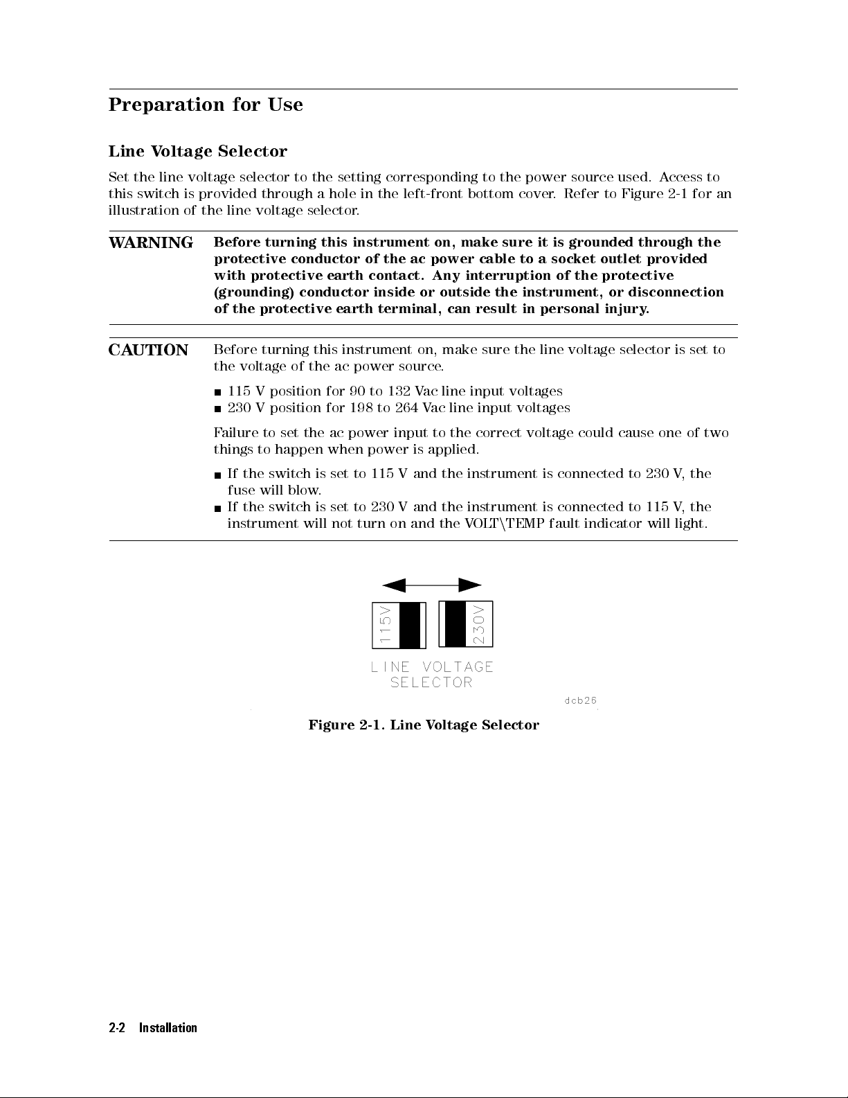
Line Voltage Selector
Set the line voltage selector to the setting corresponding to the power source used. Access to
this switch is provided through a hole in the left-front bottom cover. Refer to Figure 2-1 for an
illustration of the line voltage selector.
WARNING
CAUTION
Before turning this instrument on, make sure it is grounded through the
protective conductor of the ac power cable to a socket outlet provided
with protective earth contact. Any interruption of the protective
(grounding) conductor inside or outside the instrument, or disconnection
of the protective earth terminal, can result in personal injury.
Before turning this instrument on, make sure the line voltage selector is set to
the voltage of the ac power source.
115 V position for 90 to 132 Vac line input voltages
230 V position for 198 to 264 Vac line input voltages
the
,
V
the
,
V
light.
two
ailure
F
things
to
the
If
fuse
the
If
instrument
set
to
happen
switch
will
switch
the
blow
will
is
.
is
power
ac
when
set
set
not
power
to
to
turn
115
230
input
V
V
on
to
applied.
is
and
and
and
the
instrument
the
instrument
the
V
the
correct
TEMP
n
T
OL
voltage
connected
is
connected
is
fault
could cause
to
to
indicator
one of
230
115
will
2-2
Figure 2-1. Line Voltage Selector
Installation
Page 27

400 Hz Option
The HP 70001A Mainframe is available with an option that allows it to operate on a power-line
frequency of 400 Hz. The 400 Hz option comes with an external in-line 600 V-A isolation
transformer that must be used when the instrument uses a 400 Hz power source.
WARNING
Never operate a 400 Hz option instrument on a 400 Hz power line without
using the in-line isolation transformer supplied for this purpose.Failure
to follow this precaution can create a shock hazard which may result in
personal injury.
The in-line isolation transformer must be removed from the 400 Hz option for 50/60 Hz power
source operation. Failure to remove the in-line 400 Hz transformer will result in the 400 Hz
transformer input fuse. When the isolation transformer is removed, a standard power cord
must be used. The in-line transformer must be reinstalled when using a 400 Hz power source,
in order to protect the user from electric shock hazard.
Fuse Replacement
the
a
is
fuse
on
20
by
5
removal
mm
The line
back of
the instrument.
fuse rated
fuse
at 6.3
for
instrument
this
250
A,
Also
,
V
included
part
HP
located
is
number
in
this
inside
the
housing
2110-0703.
power
spare
a
is
Refer
cord
to
receptacle
The
.
fuse
Figure
2-2
housing
fuse
for
and replacement.
Figure
2-2.
Line
Fuse
Removal
Replacement
and
Installation
2-3
Page 28
Cabling
The HP-MSIB cables are connected in a serial (daisy-chain) manner, coupling the input of one
element to the output of next until the loop is completed.
Remote Operation
The use of long HP-MSIB cables to separate the mainframe and display, or other products
supporting HP-MSIB, allows remote operation. Since the signals on the HP-MSIB are digital,
only measurement speed is slightly degraded.
Addressing
The HP 70001A Mainframe does not have an HP-MSIB address. The mainframe acts as an
HP-MSIB arbitrator, allocating time on the HP-MSIB bus to any module or device designed to
work with an HP 70000 Series system that requests it.
Adjustments
The HP 70001A Mainframe has only internal service-related adjustments. These adjustments
should
only
attempted
be
qualied
by
technical
personnel.
2-4
Installation
Page 29

Module Installation and Removal
Module Installation
To install modules into a mainframe, follow these steps.
1. Turn the mainframe o.
2. Swing open (down) the front door. Note that the door will not swing down unless the line
switch is o.
3. Slide the module into the mainframe.
4. Tighten the module latch using an 8 mm hex-balldriver.
5. Connect intermodule cabling.
Module Removal
The removal of modules is accomplished by following these steps.
1. Turn the mainframe o.
2. Disconnect
3. Swing
Loosen
4.
Slide
5.
open the
and
the
Note
UTION
CA
intermodule cabling.
door
front
out
should
is
the
of
not
must
the
be
modules
disengage
module
Care
of
moved
Modules
adjacent
Be sure
ower
(P
.
module
mainframe
taken
carefully
slid
be
switch
latch
.
when
easily
can
guided
straight
check
to
must
an 8
using
installing
be
into
into
of
rear
the
o.)
be
mm hex-balldriver
removing
and
out
and
its
of
of the
scratched
out
or
and
module
the
modules
dented
slot.
mainframe slots
.
.
front
The
.
module
the
if
or the
edges of the module covers may contact and abrade the covers of adjacent
modules and mainframe guides.
If extreme environmental conditions exist where dust and debris may be drawn
into the air ow and distributed throughout the instrument, a Frame-Fine
Filter (HP part number 70000-40017) can be ordered from the nearest HP Sales
.
and
Service
Oce
panels
being
sharp
Installation
2-5
Page 30

Page 31

3
Specications
The following specications apply to the HP 70001A mainframe.For system specications,
refer to the \Specications" chapter of the installation and verication manual for the system
master.
Specications
Specications describe warranted performance over the temperature range 0Cto55C (except
where noted) after one hour of continuous operation.
Nominal V
Nominal
performance
General
emperature
T
values
parameters
Specications
EMI
Warm-up time
Weight
(nominal value) 14.5 kg (32 lb) (mainframe only)
Dimensions
Input
ower
P
C
A
Line Ranges
VA Rating
alues
provide
useful
information
by
.
Operation
+55
to
0C
Radiated
within
is
MIL-STD
interference
requirements
the
Class
,
461B
One hour from a cold start
(0to 55C)
Height 177 mm (6.97in)
Width
Length
90|132
198|264 V
103|132 V
310 W maximum
A maximum
570 V
non-warranted,
giving
functional,
but
Storage
C
40
0
to
C
of
RE02
A1c
1
(16.75
mm
425
(20.7
mm
526
ac
V
ac
47|66
47|66 Hz
ac 365|444 Hz
(with Option 400)
+75
Hz
in)
in)
C
1
mainframe
The
an
into
instrument,
requires
the
maximum
a
other
elements
of
minutes
5
may
require
warm-up
hour
1
however
time;
warm-up
time
,
.
congured
when
Specications
3-1
Page 32

Page 33

4
Verication
This chapter normally contains unit performance-verication tests, which evaluate the
electrical performance of the unit against its specications. There are no performance-
verication tests that apply to the HP 70001A mainframe specications.
Power-On Self-Test
The act of turning on an HP 70000 Series system causes any modules installed in the system to
execute a power-on self-test. The mainframe is not involved in these tests except in supplying
power and communication for the modules.
detailed
a
or
F
installation
the
ault
F
The HP
Indicators
70001A
indicate a
Chapter 5,
explanation
verication
and
of
Mainframe
condition
the
fault,
\Troubleshooting."
the
has
power-on
manual
OL
V
must
for
T/TEMP
cleared
be
self-tests
system
the
CURRENT
,
before
refer
,
the
master
,
the
to
.
I/O
and
mainframe
\Troubleshooting"
fault
indicators
will
.
operate
If
Refer
.
chapter
of
any
of
these
to
erication 4-1
V
Page 34

Page 35

Troubleshooting
This chapter provides troubleshooting information on the HP 70001A mainframe. Problem
isolation and diagnosis related to the front-panel fault indicator lights, fan operation, fuse
replacement, and power-on light are discussed as operator-level repairs.
Turn On
When the HP 70001A as part of an HP 70000 Modular Measurement System is turned on, the
mainframe monitors its condition as it brings power and cooling air up to specication. Once
power
The
The
The
cooling
and
T/TEMP
OL
ON
power
V
CURRENT
established,
is
should
light
I/O
and
indicator
fault
come
fault
modules
the
and
on
indicators
should
not
begin
on.
stay
should
light.
their
blink
self-test
and
on
sequences
turn o.
then
.
5
After
complete
is
models
not
.
CT
A
about
may
light.
inside
and
a
the
,
have
The
the
ERR
minute
power
fourth
a
circuitry
power
of
lights
these
indicator
ON
fault-indicator
for
receptacle
all
lights
this
the
should
function
on
modules
settle
only
the
is
labeled
back
the
instrument
the
in
down
mainframe
AIR FLOW
should be
the
of
steady
a
to
. This
disabled.
instrument.
The
During
will
state
After the
that
Note
Line
6.3
A
fan
this
turning
be
.
should
Fuse
250
A,
noise
self-test,
module
remain
V
be
will
and
on
self-test
on.
older
Some
indicator
line fuse
noticeable
module
the
o.
should
located
is
The most common reason for an open fuse is improper setting of the line voltage selector
however, internal problems can also cause a fuse to open.
See Figure 2-2
Manual
for troubleshooting information.
for fuse removal and replacement information. Refer to the
HP 70001A Service
light
,
roubleshooting 5-1
T
Page 36

Fault Indicators
The HP 70001A has three fault indicators. While these indicators are located in the mainframe,
problems external to the mainframe can cause the indicators to turn on. External problems
should be investigated before troubleshooting the mainframe.
VOLT/TEMP If this fault indicator is on steady, check for the following problems before
deciding the mainframe needs repair.
Note
Temperature
limits
input
Low
voltage
ery long
V
drop
.
line
a
as
ac wiring
below an
will
This
result.
Excessive ambient temperature, exceeding 55C will cause the
VOLT/TEMP fault indicator to come on and stay on. Move
the mainframe to a cooler environment and wait for the
temperature to decrease to the normal operation range.1When
the temperature decreases the mainframe will restart itself.
If the indicator goes out after the mainframe has cooled the
mainframe is probably not at fault.
If the problem persists; when the mainframe attempts to restart
itself, verify that both cooling fans are operating by checking
the airow into both of the rear-panel fan-intake openings of
the mainframe.
the line
If
agree
come
will
selector
V
115
V
230
the
If
voltage is
with the
on.
switch
position
position
voltage
low
low or
input voltage
as
the
follows
for
for
90|132
198|264
Check
condition
the voltage
, the
input
ac
.
corrected,
is
T/TEMP
VOL
voltage
line
ac
V
ac
V
selector
and
input
input
line
the
setting
fault
set
voltage
voltage
unit
does
indicator
voltage
the
.
restart
will
.
itself.
mainframe
the
runs
acceptable limit,
the
cause
to
is
cure
The
cause
may
when
mainframe
correct the
power
ac
the
mainframe
the
to cycle
on and
power wiring
voltage
at
applies
o. No
damage will
or voltage
its
.
load
to
the
occur
not
to
ac
A ashing VOLT/TEMP fault indicator can be caused by an
impedance mismatch between the ac line and the mainframe
input. This usually occurs only at extremely low temperatures
(below 0C). The cold input thermistors (now a high impedance)
reduce the
and the
sensed line
1
Keep in mind
that the internal temperature of the instrument will change with a
corresponding change in the ambient
a change in ambient temperature and
voltage
line
mainframe
voltage
shuts
rise
to
room temperature
under
An
.
o.
and
voltage
reduced
The
unit
the
, and that there is a delay between
a change in internal temperature
condition
load
back
turns
. It can take 20
is
allows
on.
minutes or more for an overheated mainframe to cool internally to an acceptable
temperature, since no cooling air is being moved by the fans when the supply is shut down.
Troubleshooting
5-2
sensed
the
Page 37

This cycling will continue until the input thermistors warm up
to a point where the sensed voltage is within tolerance.At
this point the fault indicator stops ashing, the mainframe is
operational.
If the condition does not go away after several minutes, check
the input line voltage under load or change the ambient
operating temperature.
High output
voltage and
Fan voltage
failure
These two conditions will also cause the the VOLT/TEMP fault
indicator to come on and the instrument will latch in a fault
condition. The mainframe is in need of internal repair or
adjustment. It will shut down and not attempt to restart until
ac line power is cycled.
CURRENT This circuitry senses and indicates if the load on the mainframe power supply
is too high. Upon sensing an over-current condition, the power supply is shut
down and latched. It will not attempt to restart until ac line power is cycled.
If a CURRENT fault indicator is on, check for a faulty module before
attempting to repair the mainframe. The following steps will help isolate the
problem.
Turn
1.
Remove
2.
Cycle
3.
NO
YES
mainframe
the
all
power
the
Turn
power
repair
system
repair
If the
been
internal
pin
50
Refer
the
o
each
procedures in
master or
alternatives.
CURRENT indicator
removed from
module
to
o.
modules
the
Is
.
mainframe
the
time)
problem.
connectors
HP
the
the
from
CURRENT
and
the
until
installation
the
service
the
the mainframe
Check
70001A
to
Service
mainframe
indicator
by
one
faulty
module
manual
on
still
is
ensure
not
are
Manual
.
still
replace
one
and
related
when
mainframe
the
,
the
that
shorting
on?
modules
the
identied.
is
the
the
manual
faulty
modules
verication
to
of
all
probably
grounding springs
the 40
KHz to
for additional
(cycling
the
to
Refer
the
for
module
for
have
an
has
on the
ground.
troubleshooting
information.
roubleshooting 5-3
T
Page 38

I/O This circuitry senses the readiness of the external HP-MSIB. If the indicator is
on, HP-MSIB communications are inhibited. The I/O fault indicator light will be
on if one of the following conditions is true.
The external HP-MSIB loop is not complete. Check that both ends of all
HP-MSIB cables are securely connected.
2
Not all the elements on the external HP-MSIB loop have the power
turned on. Verify that the power is on to all mainframes and stand-alone
instruments on the external HP-MSIB.
The mainframe is in need of repair.
HP-MSIB communication will resume as soon as the problem is corrected.
If an I/O light fault is indicated, the following steps will help isolate the
problem.
Disconnect both HP-MSIB cables from the mainframe at the mainframe
connectors. Is the I/O fault indicator still on?
NO The problem is either with the cables, or the element that was
connected to the mainframe with the cables.
does
with
on?
connectors
not
these
for
probably
is
Loop each
If the
come
cables
troubleshooting
The
YES
faulty
I/O
on
is
HP
Remove
.
cable
light
either
for
faulty
70001A
to
\IN"
comes
on,
cable
to
Refer
.
information.
Mainframe
modules
the
all
\OUT"
that
then
,
the
or
to
cable
the
service
one of
.Does
mainframe
the
faulty
is
element
manual
the
the
If
.
connected
for
installed
still
light
HP-MSIB
light
the
element
that
modules
come
.
to
information.
time
a
at
dierent
a
in
mainframe
the
manual
until
module
for
a
or
repair
Note
es
Y
No
mainframe
The
Manual
Replace
located.
is
occurs
only
problem
the
faulty module
the
for
the
is
troubleshooting
the
one
module
the
slot
the
modules
Try
one
in
follows
service
module
.Refer
faulty
It is possible that a module may disrupt all HP-MSIB communication with no
HP
the
mainframe fault or no module error lamp turned on.
2
more
If
cables
than
must
mainframe
one
connected
be
used,
is
otherwise;
or
the
if
HP-MSIB
other
elements
will not
with no external elements is used, there should be no HP-MSIB
external HP-MSIB connectors of that mainframe
, although a single cable looped from
connected to
are
operate
.
cables connected to the
input connector to the output connector will allow the mainframe to operate
70001A
faulty
If
slot.
connector
faulty
is
instructions
the
single
a
If
Service
module
problem
the
faulty
is
Refer
.
HP-MSIB
mainframe
.
slot
or
If
.
to
.
all
,
the
Troubleshooting
5-4
Page 39

If problems persist, refer to the installation and verication manual for the system master or
the
HP 70001A Service Manual
for additional troubleshooting information.
Keep in mind that mainframe internal adjustments or repairs should only be attempted by
qualied technical personnel. Review the \Hazards of Internal Repair or Adjustment" and
associated warning notice in Chapter 1, \General Information."
roubleshooting 5-5
T
Page 40

Page 41
Index
A
accessories supplied, 1-5
C
cooling, 1-2
E
ESD
heel-strap, 1-9
protection, 1-9
mat;oor,
Static
mat;table,
Static
wrist-strap,
1-9
1-9
1-9
F
1-6
1-6
5-2
,
5-4
,
5-4
failure
fault
recovery,
indicators
CURRENT,
1-6
I/O,
T/TEMP,
OL
V
,
5-4
fuse
location,
replacement,
size,
2-3
2-3
2-3
H
help, 1-10
HP-IB, 1-7
I
installing
modules,
2-5
L
line voltage selector, 2-2
M
MSIB, 1-7
O
option, 400Hz, 2-3
options, 1-5
P
packaging, 1-4
containers, 1-12
power
input,
output,
power
1-2
1-2
requirements,
R
removing
modules,
2-5
S
4-1
test,
self
number
serial
1-3
label,
1-4
,
prex,
sux,
shipping
1-3
1-3
containers,
specications
EMI, 3-1
power requirements, 3-1
temperature, 3-1
U
updating
manuals,
1-4
W
weight, 3-1
3-1
1-12
Index-1
Page 42

 Loading...