

Page 1

Agilent 6890
Gas Chromatograph
Maintaining Your GC
Agilent Technologies
Page 2

Notices
© Agilent Technologies, Inc. 2007
No part of this manual may be reproduced
in any form or by any means (including
electronic storage and retrieval or translation into a foreign language) without prior
agreement and written consent from Agilent Technologies, Inc. as governed by
United States and international copyright
laws.
Manual Part Number
G1530-90010
Edition
First edition, March 2007
Printed in USA
Agilent Technologies, Inc.
2850 Centerville Road
Wilmington, DE 19808-1610 USA
Warranty
The material contained in this document is provided “as is,” and is subject to being changed, without notice,
in future editions. Further, to the maximum extent permitted by applicable
law, Agilent disclaims all warranties,
either express or implied, with regard
to this manual and any information
contained herein, including but not
limited to the implied warranties of
merchantability and fitness for a particular purpose. Agilent shall not be
liable for errors or for incidental or
consequential damages in connection
with the furnishing, use, or performance of this document or of any
information contained herein. Should
Agilent and the user have a separate
written agreement with warranty
terms covering the material in this
document that conflict with these
terms, the warranty terms in the separate agreement shall control.
Safety Notices
CAUTION
A CAUTION notice denotes a hazard. It
calls attention to an operating procedure, practice, or the like that, if not
correctly performed or adhered to,
could result in damage to the product
or loss of important data. Do not proceed beyond a CAUTION notice until
the indicated conditions are fully
understood and met.
WARNING
A WARNING notice denotes a hazard.
It calls attention to an operating procedure, practice, or the like that, if not
correctly performed or adhered to,
could result in personal injury or
death. Do not proceed beyond a
WARNING notice until the indicated
conditions are fully understood and
met.
Page 3

Contents
1 About Maintaining the GC
Overview of Maintenance 10
Tools and Materials Required for Maintenance 12
Safety Information 14
Preparing the GC for Maintenance 15
2 Maintaining Capillary Columns
Consumables and Parts for Columns 18
To Install a Capillary Column Hanger 19
To Condition a Capillary Column 20
To Cut a Loop from a Column 23
To Reverse a Column and Bakeout Contaminants 24
To Attach a Capillary Column Using SilTite Metal Fittings 26
To Disconnect Fused Silica Tubing From a SilTite Fitting 29
3 Maintaining the Split/Splitless Inlet
Consumables and Parts for the Split/Splitless Inlet 32
Exploded Parts View of the Split/Splitless Inlet 35
To Install a Capillary Column with the Split/Splitless Inlet 36
To Change the Septum on the Split/Splitless Inlet 40
To Clean the Septum Seat in the Insert Assembly of the Split/Splitless
Inlet 42
To Change the Liner and O-Ring on the Split/Splitless Inlet 44
To Replace the Gold Seal on the Split/Splitless Inlet 46
To Replace the Filter in the Split Vent Line 48
To Clean the Split/Splitless Inlet 49
To Bakeout Contaminants from the Split/Splitless Inlet 51
4 Maintaining the Purged Packed Inlet
Consumables and Parts for the Purged Packed Inlet 54
Exploded Parts View of the Purged Packed Inlet 57
To Install a Capillary Column with the Purged Packed Inlet 58
To Change the Septum on the Purged Packed Inlet 62
Maintaining Your GC 3
Page 4

To Clean the Septum Seat in the Purged Packed Inlet 64
To Install an Adapter on the Purged Packed Inlet 66
To Change the O-Ring on the Purged Packed Inlet 68
To Change the Glass Liner on the Purged Packed Inlet 69
To Install an Insulation Cup on the Purged Packed Inlet 71
To Clean the Purged Packed Inlet 72
To Bakeout Contaminants from the Purged Packed Inlet 74
To Install a Packed Metal Column 75
To Install a Packed Column Adapter on a Detector Fitting 77
To Install a Packed Glass Column 79
To Condition a Packed Column 82
To Install Ferrules on a Packed Metal Column 84
5 Maintaining the COC Inlet
Consumables and Parts for the COC Inlet 86
Exploded Parts View of the COC Inlet 89
To Install a Capillary Column with the COC Inlet 90
To Check the Needle-to-Column Size on the COC Inlet 93
To Change a Septum on the COC Inlet 94
To Install an Insert on the COC Inlet 96
To Clean the COC Inlet 98
To Replace the Needle Support Assembly in a 7683B Injector 100
To Replace a Needle in a Syringe 103
To Replace the Fused Silica Needle in a Syringe for the COC Inlet 104
To Bakeout Contaminants from the COC Inlet 106
6 Maintaining the PTV Inlet
Consumables and Parts for the PTV Inlet 108
Exploded Parts View of the PTV Inlet 110
To Install a Capillary Column with the PTV Inlet 111
To Clean the Septumless Head on the PTV Inlet 114
To Replace the Septumless Head Teflon Ferrule on the PTV Inlet 117
To Change the Septum on the PTV Inlet 119
4 Maintaining Your GC
Page 5

To Clean the Septum Seat in the Septum Head Assembly of the PTV
To Change the Liner on the PTV Inlet 123
To Replace the Inlet Adapter for the PTV Inlet 126
To Replace the Filter in the Split Vent Line 128
To Bakeout Contaminants from the PTV Inlet 129
7 Maintaining the VI
Consumables and Parts for the VI 132
Exploded Parts View of the VI 134
To Install a Capillary Column with the VI 135
To Attach a Sample Transfer Line to the VI 138
To Remove the VI Interface 139
To Clean the VI 140
To Install the VI Interface 141
To Replace the Filter in the Split Vent Line 142
Inlet 121
To Bakeout Contaminants from the VI Inlet 143
8 Maintaining the FID
Consumables and Parts for the FID 146
Exploded Parts Views of the FID 149
Selecting an FID jet 151
To Attach a Capillary Column Adapter on an Adaptable FID 153
To Install a Capillary Column in the FID 155
To Replace the FID Collector Assembly 158
To Replace an FID Jet 160
To Perform Maintenance on the FID Collector Assembly 163
To Check the FID Leakage Current 171
To Check the FID Baseline 172
To Install the FID Insulation Cup Assembly (Adaptable FID Only) 173
To Install the Optional FID PTFE Chimney Insert 175
To Bakeout the FID 176
9 Maintaining the TCD
Consumables and Parts for the TCD 180
Maintaining Your GC 5
Page 6

To Install a Capillary Column in the TCD 182
To Install the Optional TCD Capillary Column Adapter 184
To Install a Capillary Column with the Optional TCD Capillary Column
Adapter 185
To Bakeout Contaminants from the TCD 187
10 Maintaining the uECD
Important Safety Information About the uECD 190
Consumables and Parts for the uECD 192
Exploded Parts View of the uECD 194
To Replace the uECD Fused Silica Indented Mixing Liner and Install the
Makeup Gas Adapter 195
To Install a Capillary Column in the uECD 198
To Install the Detector Insulating Cup 200
To Bakeout the uECD 202
11 Maintaining the NPD
Consumables and Parts for the NPD 206
Exploded Parts View of the NPD 209
Selecting an NPD jet 210
To Attach a Capillary Column Adapter on an Adaptable NPD 212
To Install a Capillary Column in the NPD 214
To Replace the NPD Bead Assembly 217
To Maintain the NPD Collector, Ceramic Insulators, and Jet 222
To Check the NPD Leakage Current 228
12 Maintaining the FPD
Consumables and Parts for the FPD 230
Exploded Parts View of the FPD 232
To Install a Capillary Column Adapter in the FPD 233
To Attach a Capillary Column to the FPD 235
To Change the FPD Wavelength Filter 237
To Remove the FPD Vent Tube 240
To Replace the FPD Ignitor 242
To Install the FPD Vent Tube and Cover 244
6 Maintaining Your GC
Page 7

13 Maintaining a Valve
Consumables and Parts for Valves 246
Exploded Parts View of GC Rotary Valves 247
To Replace a Gas Sampling Valve Loop 248
To Align a Rotary Valve Rotor 250
To Replace a Rotary Valve in the Valve Box 251
To Remove the Upper Valve Box 254
To Install the Upper Valve Box 256
Maintaining Your GC 7
Page 8

8 Maintaining Your GC
Page 9

Agilent 6890 Gas Chromatograph
Maintaining Your GC
1
About Maintaining the GC
Overview of Maintenance 10
Tools and Materials Required for Maintenance 12
Safety Information 14
Preparing the GC for Maintenance 15
This section provides an overview of the maintenance
procedures included in this document. It also lists the tools
needed for routine maintenance and the safety information one
should be aware of before performing a maintenance task.
Agilent Technologies
9
Page 10

1 About Maintaining the GC
Overview of Maintenance
Where to find a procedure
This manual details the routine tasks needed to maintain the
6890 Gas Chromatograph (GC). The procedures assume a basic
knowledge of tool use and of GC operation. Readers are, for
example, expected to know how to:
• Safely turn devices on and off
• Load methods
• Change component temperatures, flows, and pressures
• Make typical pneumatic connections using Swagelok and
other standard fittings
Included in this manual are chapters on maintaining the
following GC components:
• Capillary Columns
• Split/Splitless Inlet
• Purged Packed Inlet
• COC Inlet
• PTV Inlet
• Volatiles Inlet (VI)
• FID
• TCD
• uECD
• NPD
• FPD
• Valves
Each chapter includes:
• A list of the most commonly used consumables and parts for
the component
• An exploded parts view of the component
• Detailed procedures for routine maintenance tasks
associated with the component
10 Maintaining Your GC
Page 11

Early Maintenance Feedback feature
The Agilent Lab Monitor & Diagnostic Software includes the
capability to alert users of upcoming maintenance needs. This
feature, called Early Maintenance Feedback, notifies users when
a counter (such as a septum counter, jet cleaning counter,
injection counter, or uECD wipe test counter) has reached the
specified maintenance point. After performing the required
maintenance, reset the applicable counter to resume using the
Early Maintenance Feedback feature. Refer to the features
provided by the Agilent Lab Monitor & Diagnostic Software for
more details on this.
About Maintaining the GC 1
Maintaining Your GC 11
Page 12

1 About Maintaining the GC
Tools and Materials Required for Maintenance
Table 1 lists the tools needed for most GC maintenance
procedures. The specific tools required to perform a
maintenance procedure are listed in step 1 of the procedure.
Tab le 1 Tools and materials for GC maintenance
Common tools
Wrench, angled, septum nut (19251-00100)
Wrench, open-end, 1/4-inch and 5/16-inch (8710-0510)
Wrench, open-end, 9/16-inch and 7/16-inch (8710-0803)
Wrench, capillary inlet (G3452-20512)
Flathead screwdriver
Column cutter, wafer (5181-8836, 4/pk)
Driver, nut, 1/4-inch (8710-1561)
T-20 Torx key (8710-1807) or screwdriver
T-10 Torx key (8710-2140) or screwdriver
*
*
*
*
*
*
*
*
3-mm hex key wrench (8710-2411)
Electronic flow meter(s) or bubble meter(s) capable of calibrated measurements
at 1, 10, and 100 mL/min flow ranges.
Electronic leak detector
Magnifying loupe, 20X (430-1020)
Metric ruler
Bench vise (for setting Swagelok fittings)
Razor or sharp knife
Tweezers (8710-0007) or thin needle-nose pliers (8710-0004)
Needle-nose pliers
ESD wrist strap (for installing new components)
Gloves, heat-resistant (for handling hot parts)
Wooden cotton swab (for removing FID filters)
Tools and materials for cleaning procedures
Cleaning brushes—The FID cleaning kit (9301-0985) contains appropriate
brushes for cleaning detectors and inlets
Cleaning brushes—(8710-1346) For cleaning split/splitless inlet split vent
fitting, FID and collectors
12 Maintaining Your GC
Page 13

About Maintaining the GC 1
Tab le 1 Tools and materials for GC maintenance (continued)
Jet cleaning wire (.010 inch)
Clean, lint-free cloth (to protect contamination-sensitive detector parts)
Small ultrasonic cleaning bath with aqueous detergent (for cleaning detector
and inlet parts)
Gloves, clean, lint-free, nylon (large: 8650-0030, small: 8650-0029) (for handling
contamination-sensitive parts)
Steel wool, 0- or 00-grade (for cleaning an inlet’s septum seating surfaces)
* Included with the GC ship kits
Maintaining Your GC 13
Page 14

1 About Maintaining the GC
Safety Information
Before performing a maintenance task, read the important
safety and regulatory information found in the 6890 User
Information book.
14 Maintaining Your GC
Page 15

Preparing the GC for Maintenance
Before most maintenance procedures, the GC must be made
ready. The purpose of this preparation is to avoid damage to
both the instrument (electronics, columns, etc.) and the user
(shocks, burns).
Column and oven preparation
The main hazards here are temperature (burns) and column
exposure to air.
• Cool the oven by changing its setpoint to 35 °C. This allows
the oven fan to assist cooling.
• Leave the carrier gas flow On until the oven has cooled. This
protects the column from oxygen damage.
Inlet preparation
About Maintaining the GC 1
We are concerned with the possibility of burns and air intrusion
into the column.
• After the oven and columns have cooled, reduce all inlet
flows to 0.0 and turn the temperatures Off.
• For inlet-only maintenance, leave all detectors at their
normal setpoints except for the TCD filament, which should
be turned Off.
• If the column is to be removed, cap both ends to keep air out.
Detector preparation
This is another burn hazard area, plus the possibility of damage
to the very sensitive electronics.
Some detectors (uECD, FPD, NPD) require 12 hours or longer to
stabilize from the detector-off condition.
• To cool the detector, reduce the temperature setpoint to
35 °C.
• Some detectors (FID, NPD, FPD) use high voltages. The high
voltage supply is part of the electrometer. Turn it Off to
disable the high voltage.
• The filament in the TCD will be damaged if exposed to air
while hot. To protect the filament, turn it Off.
Maintaining Your GC 15
Page 16

1 About Maintaining the GC
16 Maintaining Your GC
Page 17

Agilent 6890 Gas Chromatograph
Maintaining Your GC
2
Maintaining Capillary Columns
Consumables and Parts for Columns 18
To Install a Capillary Column Hanger 19
To Condition a Capillary Column 20
To Cut a Loop from a Column 23
To Reverse a Column and Bakeout Contaminants 24
To Attach a Capillary Column Using SilTite Metal Fittings 26
To Disconnect Fused Silica Tubing From a SilTite Fitting 29
Agilent Technologies
17
Page 18

2 Maintaining Capillary Columns
Consumables and Parts for Columns
See the Agilent catalog for consumables and supplies for a more
complete listing, or visit the Agilent Web site for the latest
information (www.agilent.com/chem/supplies).
Tab le 2 Nuts, ferrules, and hardware for capillary columns
Column id (mm) Description Typical use Part number/quantity
.530 Ferrule, Vespel/graphite,
0.8-mm id
Ferrule, graphite, 1.0-mm id 0.53-mm capillary columns 5080-8773 (10/pk)
Column nut, finger-tight (for
0.53-mm columns)
.320 Ferrule, Vespel/graphite,
0.5-mm id
Ferrule, graphite, 0.5-mm id 0.1-mm, 0.2-mm, 0.25-mm, and
Column nut, finger-tight (for
.100- to .320-mm columns)
.250 Ferrule, Vespel/graphite,
0.4-mm id
Ferrule, graphite, 0.5-mm id 0.1-mm, 0.2-mm, 0.25-mm, and
Column nut, finger-tight (for
.100- to .320-mm columns)
.100 and .200 Ferrule, Vespel/graphite,
0.37-mm id
0.45-mm and 0.53-mm capillary
columns
Connect column to inlet or detector 5020-8293
0.32-mm capillary columns 5062-3514 (10/pk)
0.32-mm capillary columns
Connect column to inlet or detector 5020-8292
0.1-mm, 0.2-mm, and 0.25-mm
capillary columns
0.32-mm capillary columns
Connect column to inlet or detector 5020-8292
0.1-mm and 0.2-mm capillary
columns
5062-3512 (10/pk)
5080-8853 (10/pk)
5181-3323 (10/pk)
5080-8853 (10/pk)
5062-3516 (10/pk)
Ferrule, Vespel/graphite,
0.4-mm id
Ferrule, graphite, 0.5-mm id 0.1-mm, 0.2-mm, 0.25-mm, and
Column nut, finger-tight (for
.100- to .320-mm columns)
All Ferrule, no-hole Testing 5181-3308 (10/pk)
Capillary column blanking nut Testing–use with any ferrule 5020-8294
Column nut, universal Connect column to inlet or detector 5181-8830 (2/pk)
Column cutter, ceramic wafer Cutting capillary columns 5181-8836 (4/pk)
18 Maintaining Your GC
0.1-mm, 0.2-mm, and 0.25-mm
capillary columns
0.32-mm capillary columns
Connect column to inlet or detector 5020-8292
5181-3323 (10/pk)
5080-8853 (10/pk)
Page 19
To Install a Capillary Column Hanger
Maintaining Capillary Columns 2
WARNING
WARNING
Be careful! The oven may be hot enough to cause burns. If the
oven is hot, wear heat-resistant gloves to protect your hands.
Wear safety glasses to protect your eyes from flying particles
while handling, cutting, or installing glass or fused silica capillary
columns. Use care in handling these columns to prevent puncture
wounds.
1 Prepare the column and oven for maintenance. See
“Preparing the GC for Maintenance” on page 15.
2 Select either the front or back hanger position. (Hanger is
shown in back position.)
Front position
Back position
3 Insert the ends of the hanger into the slots in the selected
position.
Maintaining Your GC 19
Page 20

2 Maintaining Capillary Columns
To Condition a Capillary Column
1 Gather the following:
• One 7/16-inch, and 1/4-inch wrenches
• No-hole ferrule (See “Consumables and Parts for
Columns” on page 18.)
• Column nut
=
WARNING
Do not use hydrogen as the carrier for conditioning! It could vent
into the oven and present an explosion hazard.
2 Prepare the column and oven for maintenance. See
“Preparing the GC for Maintenance” on page 15.
WARNING
WARNING
Be careful! The oven and/or detector may be hot enough to cause
burns. If the detector is hot, wear gloves to protect your hands.
Wear safety glasses to protect your eyes from flying particles
while handling, cutting, or installing glass or fused silica capillary
columns. Use care in handling these columns to prevent puncture
wounds.
3 Install the column into the inlet using the new ferrules. See:
• “To Install a Capillary Column with the Split/Splitless
Inlet” on page 36
• “To Install a Capillary Column with the Purged Packed
Inlet” on page 58
• “To Install a Capillary Column with the COC Inlet” on
page 90
• “To Install a Capillary Column with the PTV Inlet” on
page 111
• “To Install a Capillary Column with the VI” on page 135
20 Maintaining Your GC
Page 21

Maintaining Capillary Columns 2
4
Cap the detector column fitting.
5 Set a minimum velocity of 30 cm/s, or as recommended by
the column manufacturer. Let gas flow through the column at
room temperature for 15 to 30 minutes to remove air.
WARNING
WARNING
6 Program the oven from room temperature to the maximum
temperature limit for the column. Increase the temperature
at a rate of 10 to 15 °C/min. Hold at the maximum
temperature for 30 minutes.
7 Prepare the GC for maintenance. See “Preparing the GC for
Maintenance” on page 15.
Be careful! The oven and/or detector may be hot enough to cause
burns. If the detector is hot, wear gloves to protect your hands.
Wear safety glasses to protect your eyes from flying particles
while handling, cutting, or installing glass or fused silica capillary
columns. Use care in handling these columns to prevent puncture
wounds.
8 Attach the column to the detector. For details, select your
specific detector from the following list:
• “To Install a Capillary Column in the FID” on page 155
• “To Install a Capillary Column in the NPD” on page 214
• “To Install a Capillary Column in the TCD” on page 182
• “To Install a Capillary Column in the uECD” on page 198
• “To Install a Capillary Column Adapter in the FPD” on
page 233
Maintaining Your GC 21
Page 22

2 Maintaining Capillary Columns
9
Restore the analytical method.
• For FID or FPD, immediately turn off the flame.
• For NPD, immediately turn off the bead.
10 After the GC becomes ready, wait 10 minutes, then ignite the
detector flame or bead.
22 Maintaining Your GC
Page 23

To Cut a Loop from a Column
1 Gather the following:
2 Prepare the inlets for maintenance. See “Preparing the GC
Maintaining Capillary Columns 2
• New ferrule(s) for the column inlet connection
• Column cutter
for Maintenance” on page 15.
WARNING
WARNING
Be careful! The oven and/or inlet may be hot enough to cause
burns. If either is hot, wear heat-resistant gloves to protect your
hands.
Wear safety glasses to protect your eyes from flying particles
while handling, cutting, or installing glass or fused silica capillary
columns. Use care in handling these columns to prevent puncture
wounds.
3 Loosen the inlet column nut and remove the column from the
inlet.
4 Uncoil one loop of column from the column hanger.
5 Cut the unwanted loop from the column.
6 Install the column into the inlet using the new ferrules. See:
• “To Install a Capillary Column with the Split/Splitless
Inlet” on page 36
• “To Install a Capillary Column with the Purged Packed
Inlet” on page 58
• “To Install a Capillary Column with the COC Inlet” on
page 90
• “To Install a Capillary Column with the PTV Inlet” on
page 111
• “To Install a Capillary Column with the VI” on page 135
Maintaining Your GC 23
Page 24

2 Maintaining Capillary Columns
To Reverse a Column and Bakeout Contaminants
1 Gather the following:
• 1/4-inch wrench
• Column cutter
2 Prepare the GC for maintenance. See “Preparing the GC for
Maintenance” on page 15.
WARNING
WARNING
Be careful! The oven and/or detector may be hot enough to cause
burns. If the detector is hot, wear gloves to protect your hands.
Wear safety glasses to protect your eyes from flying particles
while handling, cutting, or installing glass or fused silica capillary
columns. Use care in handling these columns to prevent puncture
wounds.
3 Disconnect the column from the inlet and detector.
4 If necessary, cut a loop from the column. (See “To Cut a Loop
from a Column” on page 23.) Do not attach the column to the
inlet.
5 Remove the column from the hanger and reverse its position
(inlet and detector ends) and place the column back on the
hanger.
6 Attach the column to the inlet.
Select your specific inlet from the following list:
• “To Install a Capillary Column with the Split/Splitless
Inlet” on page 36
• “To Install a Capillary Column with the Purged Packed
Inlet” on page 58
• “To Install a Capillary Column with the COC Inlet” on
page 90
• “To Install a Capillary Column with the PTV Inlet” on
page 111
• “To Install a Capillary Column with the VI” on page 135
7 Attach your column to the detector.
Select your specific detector from the following list:
• “To Install a Capillary Column in the FID” on page 155
• “To Install a Capillary Column in the NPD” on page 214
24 Maintaining Your GC
Page 25

Maintaining Capillary Columns 2
• “To Install a Capillary Column in the TCD” on page 182
• “To Install a Capillary Column in the uECD” on page 198
• “To Install a Capillary Column Adapter in the FPD” on
page 233
8 Set the column flow to the normal operating value, or set the
capillary column gas velocity to 30 cm/s.
For split splitless, PTV, and VI inlets select split mode and set
the split vent flow to 200 mL/min.
9 Purge the column with carrier flow for at least 10 minutes
before heating the oven.
10 Set the inlet temperature to 300 °C or 25 °C above the
normal operating temperature.
11 Set the column oven 25 °C above the GC method final oven
temperature to bake contaminants out of the inlet, mostly
through the split vent. Do not exceed the column
manufacturer’s maximum temperature limit.
12 Bakeout for 30 minutes.
Maintaining Your GC 25
Page 26

2 Maintaining Capillary Columns
To Attach a Capillary Column Using SilTite Metal Fittings
This procedure is used to attach a capillary column to a
Microfluidic splitter or switch or an Ultimate Union.
1 Gather the following:
• SilTite ferrules (see Table 3)
• Swaging nut for SilTite ferrules (G2855-20555)
• Two 1/4-inch open-end wrenches
• One 7/16-inch open-end wrench
• Column cutting tool (5181-8836)
• Internal nut (G2855-20530)
• Lint free gloves
Tab le 3 Available SilTite metal ferrule packages
CAUTION
Part number SilTite ferrule description
5188-5361 For 0.2- to 0.25-mm columns
5188-5362 For 0.32-mm columns
5188-5363 For 0.53-mm columns
Wear clean, lint-free gloves to prevent contamination of parts with
dirt and skin oils.
2 Pass the tubing end through the internal nut and SilTite
ferrule leaving approximately 1 cm of fused silica tubing
protruding beyond the ferrule. Thread the swaging nut onto
the internal nut with the tube protruding.
26 Maintaining Your GC
Page 27

Maintaining Capillary Columns 2
Using two wrenches against each other, tighten the two nuts
3
together a little at a time, occasionally checking to see if the
ferrule is gripping the tube. When the ferrule just starts to
grip, notice position of the nuts and then tighten one of the
nuts by turning 45 to 60 degrees of rotation, but no more
than 60 degrees (one flat).
4 Remove the swaging nut.
Maintaining Your GC 27
Page 28
2 Maintaining Capillary Columns
NOTE
5
Using a wafer column cutter, trim the tubing at the small end
of the ferrule, leaving approximately 0.3 mm of tubing
extending beyond the ferrule.
Check the end of the tube with a magnifier. The end of the
tube need not be perfectly square, but should not have cracks
that extend under the ferrule.
It is important that the tube end does not extend beyond 0.5 mm from the
end of the ferrule.
6 Insert the assembled ferrule and nut into the SilTite fitting.
Tighten with a wrench by only 15 to 20 degrees of rotation.
28 Maintaining Your GC
Page 29

Maintaining Capillary Columns 2
To Disconnect Fused Silica Tubing From a SilTite Fitting
Loosen and remove the internal nut. If tubing and ferrule do not
come free, insert a pointed object (pen, paper clip) into the
ferrule release hole and press firmly. You will hear a click as the
ferrule releases.
The SilTite ferrule seal should remain leak-free for many
disconnections and reconnections.
Maintaining Your GC 29
Page 30

2 Maintaining Capillary Columns
30 Maintaining Your GC
Page 31

Agilent 6890 Gas Chromatograph
Maintaining Your GC
3
Maintaining the Split/Splitless Inlet
Consumables and Parts for the Split/Splitless Inlet 32
Exploded Parts View of the Split/Splitless Inlet 35
To Install a Capillary Column with the Split/Splitless Inlet 36
To Change the Septum on the Split/Splitless Inlet 40
To Clean the Septum Seat in the Insert Assembly of the Split/Splitless
Inlet 42
To Change the Liner and O-Ring on the Split/Splitless Inlet 44
To Replace the Gold Seal on the Split/Splitless Inlet 46
Check for leaks. 47
To Replace the Filter in the Split Vent Line 48
To Clean the Split/Splitless Inlet 49
To Bakeout Contaminants from the Split/Splitless Inlet 51
Agilent Technologies
31
Page 32

3 Maintaining the Split/Splitless Inlet
Consumables and Parts for the Split/Splitless Inlet
See the Agilent catalog for consumables and supplies for a more
complete listing, or visit the Agilent Web site for the latest
information (www.agilent.com/chem/supplies).
\<space>
Tab le 4 Split, splitless, direct, and direct connect inlet liners
Mode Description Deactivated Part number
Split Low-pressure drop, glass wool, single taper, 870 µL Yes 5183-4647
Split Glass wool, 990 µL No 19251-60540
Split—Manual only Empty pin and cup, 800 µL No 18740-80190
Split—Manual only Packed pin and cup, 800 µL No 18740-60840
Splitless Single taper, glass wool, 900 µL Yes 5062-3587
Splitless Single taper, no glass wool, 900 µL Yes 5181-3316
Splitless Dual taper, no glass wool, 800 µL Yes 5181-3315
Splitless—Direct inject 2-mm id, quartz, 250 µL No 18740-80220
Splitless—Direct inject 2-mm id, 250 µL Yes 5181-8818
Direct inject —Headspace or
purge and trap
Direct column connect Single taper, splitless 4-mm id Yes G1544-80730
Direct column connect Dual taper, splitless 4-mm id Yes G1544-80700
1.5-mm id, 140 µL No 18740-80200
Tab le 5 Nuts, ferrules, and hardware for capillary columns
Column id (mm) Description Typical use Part number/quantity
.530 Ferrule, Vespel/graphite,
0.8-mm id
Ferrule, graphite, 1.0-mm id 0.53-mm capillary columns 5080-8773 (10/pk)
Column nut, finger-tight (for
0.53-mm columns)
.320 Ferrule, Vespel/graphite,
0.5-mm id
0.45-mm and 0.53-mm capillary
columns
Connect column to inlet or detector 5020-8293
0.32-mm capillary columns 5062-3514 (10/pk)
5062-3512 (10/pk)
Ferrule, graphite, 0.5-mm id 0.1-mm, 0.2-mm, 0.25-mm, and
0.32-mm capillary columns
Column nut, finger-tight (for
.100- to .320-mm columns)
32 Maintaining Your GC
Connect column to inlet or detector 5020-8292
5080-8853 (10/pk)
Page 33

Maintaining the Split/Splitless Inlet 3
Tab le 5 Nuts, ferrules, and hardware for capillary columns (continued)
Column id (mm) Description Typical use Part number/quantity
.250 Ferrule, Vespel/graphite,
0.4-mm id
Ferrule, graphite, 0.5-mm id 0.1-mm, 0.2-mm, 0.25-mm, and
Column nut, finger-tight (for
.100- to .320-mm columns)
.100 and .200 Ferrule, Vespel/graphite,
0.37-mm id
Ferrule, Vespel/graphite,
0.4-mm id
Ferrule, graphite, 0.5-mm id 0.1-mm, 0.2-mm, 0.25-mm, and
Column nut, finger-tight (for
.100- to .320-mm columns)
All Ferrule, no-hole Testing 5181-3308 (10/pk)
Capillary column blanking nut Testing–use with any ferrule 5020-8294
Column nut, universal Connect column to inlet or detector 5181-8830 (2/pk)
Column cutter, ceramic wafer Cutting capillary columns 5181-8836 (4/pk)
0.1-mm, 0.2-mm, and 0.25-mm
capillary columns
0.32-mm capillary columns
Connect column to inlet or detector 5020-8292
0.1-mm and 0.2-mm capillary
columns
0.1-mm, 0.2-mm, and 0.25-mm
capillary columns
0.32-mm capillary columns
Connect column to inlet or detector 5020-8292
5181-3323 (10/pk)
5080-8853 (10/pk)
5062-3516 (10/pk)
5181-3323 (10/pk)
5080-8853 (10/pk)
Tab le 6 Other consumables and parts for the split/splitless inlet
Description/quantity Part number
Septum retainer nut for headspace 18740-60830
Septum retainer nut 18740-60835
11-mm septum, high-temperature, low-bleed, 50/pk 5183-4757
11-mm septum, prepierced, long life, 50/pk 5183-4761
Merlin Microseal septum (high-pressure) 5182-3444
Merlin Microseal septum (30 psi) 5181-8815
Nonstick fluorocarbon liner O-ring (for temperatures up to
350 °C), 10/pk
Nonstick fluorocarbon liner O-ring for Flip Top Inlet Sealing
System, 10/pk
Graphite O-ring for split liner (for temperatures above
350 °C), 10/pk
Maintaining Your GC 33
5188-5365
5188-5366
5180-4168
Page 34

3 Maintaining the Split/Splitless Inlet
Tab le 6 Other consumables and parts for the split/splitless inlet
Description/quantity Part number
Graphite O-ring for splitless liner (for temperatures above
350 °C), 10/pk
Split trap vent replacement kit, 2 filters and 4 O-rings G1544-80530
Retaining nut G1544-20590
Gold-plated seal (standard application) 5188-5367
Gold-plated seal with cross (high split flows) (includes SS
washer)
Stainless steel washer (0.375-inch od), 12/pk 5061-5869
Reducing nut 18740-20800
Column nut, blanking plug 5020-8294
Capillary inlet preventative maintenance kit, split 5188-6496
Capillary inlet preventative maintenance kit, splitless 5188-6497
5180-4173
5182-9652
34 Maintaining Your GC
Page 35

Exploded Parts View of the Split/Splitless Inlet
Maintaining the Split/Splitless Inlet 3
Maintaining Your GC 35
Page 36

3 Maintaining the Split/Splitless Inlet
To Install a Capillary Column with the Split/Splitless Inlet
=
WARNING
Do not use hydrogen as the carrier for conditioning! It could vent
into the oven and present an explosion hazard.
1 Gather the following (see “Consumables and Parts for the
Split/Splitless Inlet” on page 32):
• Column
• Ferrule(s)
• Column nut
• Septum
• Column cutter
• Isopropanol
• Lab tissue
WARNING
WARNING
• Metric ruler
• 1/4-inch open-end wrench
• Lint-free gloves
2 Prepare the GC for maintenance. See “Preparing the GC for
Maintenance” on page 15.
Be careful! The oven and/or inlet may be hot enough to cause
burns. If either is hot, wear heat-resistant gloves to protect your
hands.
Wear safety glasses to protect your eyes from flying particles
while handling, cutting, or installing glass or fused silica capillary
columns. Use care in handling these columns to prevent puncture
wounds.
3 Verify that the correct glass liner is installed. (See
“Consumables and Parts for the Split/Splitless Inlet” on
page 32.)
4 Place the column on the hanger with the ends pointing up
and the label to the front.
CAUTION
Wear clean, lint-free gloves to prevent contamination of parts with
dirt and skin oils.
36 Maintaining Your GC
Page 37

Maintaining the Split/Splitless Inlet 3
Place a septum, capillary column nut, and ferrule on the
5
column.
Ferrule
Column nut
Septum
6 Score the column using a glass scribing tool. The score must
be square to ensure a clean break.
7 Break off the column end by supporting it against the column
cutter opposite the scribe. Inspect the end with a magnifying
loupe to make certain there are no burrs or jagged edges.
8 Wipe the column walls with a tissue dampened with
isopropanol to remove fingerprints and dust.
9 Position the column so it extends 4 to 6 mm above the end of
the ferrule. Slide the septum up the column to hold the
column nut at this position.
4%6 mm
10 Thread the column nut into the inlet but do not tighten.
Maintaining Your GC 37
Page 38

3 Maintaining the Split/Splitless Inlet
Adjust the column position so that the septum contacts the
11
bottom of the column nut. Finger-tighten the column nut
until it begins to grip the column.
12 Tighten the column nut an additional 1/4 to 1/2 turn with a
wrench so that the column cannot be pulled from the fitting
with gentle pressure.
13 Configure the new column.
14 Condition the column per the manufacturer’s
recommendation. (See “To Condition a Capillary Column” on
page 20.)
15 Install the column into the detector. See:
• “To Install a Capillary Column in the FID” on page 155
• “To Install a Capillary Column in the TCD” on page 182
• “To Install a Capillary Column in the uECD” on page 198
• “To Install a Capillary Column Adapter in the FPD” on
page 233
• “To Install a Capillary Column in the NPD” on page 214
16 After the column is installed at both inlet and detector,
establish a flow of carrier gas and purge as recommended by
the column manufacturer.
17 Restore the analytical method.
• For FID or FPD, immediately turn off the flame.
• For NPD, immediately turn off the bead.
18 After the GC becomes ready, wait 10 minutes then ignite the
detector flame or bead.
WARNING
Be careful! The oven, inlet, and/or detector may be hot enough to
cause burns. If they are hot, wear heat-resistant gloves to protect
your hands.
38 Maintaining Your GC
Page 39

Maintaining the Split/Splitless Inlet 3
19
Allow the oven, inlet, and detector to equilibrate at operating
temperature, then retighten the fittings.
Maintaining Your GC 39
Page 40

3 Maintaining the Split/Splitless Inlet
To Change the Septum on the Split/Splitless Inlet
1 Gather the following:
• Replacement septum. (See “Consumables and Parts for
the Split/Splitless Inlet” on page 32.)
• 0- or 00-grade steel wool (optional)
• Tweezers
2 Prepare the inlet for maintenance. See “Preparing the GC for
Maintenance” on page 15.
WARNING
Be careful! The oven and/or inlet may be hot enough to cause
burns. If the inlet is hot, wear heat-resistant gloves to protect your
hands.
3 Remove the septum retainer nut or Merlin cap.
4 Use tweezers to remove the septum or Merlin Microseal from
the retainer nut. Do not gouge or scratch the interior of the
septum head.
5 Firmly press the new septum or Merlin Microseal into the
fitting. The metal parts side of the Merlin Microseal should
face down (toward the oven).
40 Maintaining Your GC
Page 41

Maintaining the Split/Splitless Inlet 3
6
Install the septum retainer nut or Merlin cap and
finger-tighten. Tighten the septum retainer nut until the
C-ring is about 1 mm above the nut.
CAUTION
Overtightening the septum nut can cause contamination.
1 mm
7 Restore the analytical method.
Maintaining Your GC 41
Page 42

3 Maintaining the Split/Splitless Inlet
To Clean the Septum Seat in the Insert Assembly of the Split/Splitless Inlet
1 Gather the following:
• Replacement septum (See “Consumables and Parts for the
Split/Splitless Inlet” on page 32.)
• 0- or 00-grade steel wool (optional)
• Tweezers
• Compressed, filtered, dry air or nitrogen
2 Prepare the inlet for maintenance. See “Preparing the GC for
Maintenance” on page 15.
WARNING
Be careful! The oven and/or inlet may be hot enough to cause
burns. If either is hot, wear heat-resistant gloves to protect your
hands.
3 Unscrew the insert nut from the inlet body. Lift the septum
assembly straight up and away from the inlet to avoid
chipping or breaking the liner.
4 Remove the septum retainer nut or Merlin cap.
5 Use tweezers to remove the septum or Merlin Microseal from
the retainer nut. (See “To Change the Septum on the
Split/Splitless Inlet” on page 40.)
6 Scrub the residue from the retainer nut and septum holder
with a small piece of rolled-up steel wool and tweezers. Do
not do this over the inlet.
42 Maintaining Your GC
Page 43

Maintaining the Split/Splitless Inlet 3
7
Use compressed air or nitrogen to blow away the pieces of
steel wool and septum.
8 Replace the insert retainer nut, tightening it to firm
finger-tightness. Do not overtighten.
9 Firmly press the new septum or Merlin Microseal into the
fitting. (See “To Change the Septum on the Split/Splitless
Inlet” on page 40.)
10 Replace the septum retainer nut or Merlin cap and
finger-tighten. (See “To Change the Septum on the
Split/Splitless Inlet” on page 40.)
11 Restore the analytical method.
Maintaining Your GC 43
Page 44

3 Maintaining the Split/Splitless Inlet
To Change the Liner and O-Ring on the Split/Splitless Inlet
1 Gather the following:
• Replacement O-ring (See “Consumables and Parts for the
Split/Splitless Inlet” on page 32.)
• Replacement liner
• Tweezers
• Lint-free gloves
2 Prepare the inlet for maintenance. See “Preparing the GC for
Maintenance” on page 15.
WARNING
Be careful! The oven and/or inlet may be hot enough to cause
burns. If either is hot, wear heat-resistant gloves to protect your
hands.
3 Unscrew the insert nut from the inlet body. Lift the septum
assembly straight up and away from the inlet to avoid
chipping or breaking the liner.
4 Loosen the O-ring from the sealing surface with tweezers.
5 Grasp the liner with tweezers and pull it out.
6 Inspect the surface of the gold seal for graphite or rubber
septum contamination. If required, replace the gold seal.
(See “To Replace the Gold Seal on the Split/Splitless Inlet” on
page 46.)
44 Maintaining Your GC
Page 45

Maintaining the Split/Splitless Inlet 3
Clean the inlet if there is visible or suspected contamination.
(See “To Clean the Split/Splitless Inlet” on page 49.)
Clean O-ring residue from sealing surface.
CAUTION
Wear clean, lint-free gloves to prevent contamination of parts with
dirt and skin oils.
7 Slide a new O-ring onto the replacement liner.
8 Return the liner to the inlet, pushing it all the way in until
the liner contacts the gold seal.
9 Replace the insert retainer nut, tightening it to firm
finger-tightness. Do not overtighten.
10 Turn on the inlet. Allow the inlet and column to purge with
carrier gas for 15 minutes before heating the inlet or the
column oven.
11 Bakeout contaminants. (See “To Bakeout Contaminants from
the Split/Splitless Inlet” on page 51.)
12 Restore the analytical method.
13 Check for leaks.
Maintaining Your GC 45
Page 46

3 Maintaining the Split/Splitless Inlet
To Replace the Gold Seal on the Split/Splitless Inlet
1 Gather the following:
• Replacement gold seal (See “Consumables and Parts for
the Split/Splitless Inlet” on page 32.)
• Replacement washer
• 1/4-inch wrench (for column)
• 1/2-inch wrench
• Lint-free gloves
2 Prepare the inlet for maintenance. See “Preparing the GC for
Maintenance” on page 15.
WARNING
Be careful! The oven and/or inlet may be hot enough to cause
burns. If either is hot, wear heat-resistant gloves to protect your
hands.
3 Remove the inlet liner.
4 Remove the column from the inlet. Cap the open end of the
column to prevent contamination. Remove the insulation cup
around the base of the inlet.
5 Loosen and remove the reducing nut. Remove the washer
and seal inside the reducing nut.
CAUTION
Wear clean, lint-free gloves to prevent contamination of parts with
dirt and skin oils.
6 Put on gloves to protect the new gold seal and washer from
contamination. Put a new washer in the reducing nut and
place the new gold seal on top of it (raised portion facing
down).
46 Maintaining Your GC
Page 47

Maintaining the Split/Splitless Inlet 3
Inlet gold seal
Washer
Reducing nut
7
Replace the reducing nut and tighten securely with a wrench.
8 Replace the inlet liner.
9 Install the column and the insulation cup.
10 Bakeout contaminants. (See “To Bakeout Contaminants from
Gold seal side view
Make sure raised portion faces
down.
the Split/Splitless Inlet” on page 51.)
11 Restore the analytical method.
12 Check for leaks.
Maintaining Your GC 47
Page 48

3 Maintaining the Split/Splitless Inlet
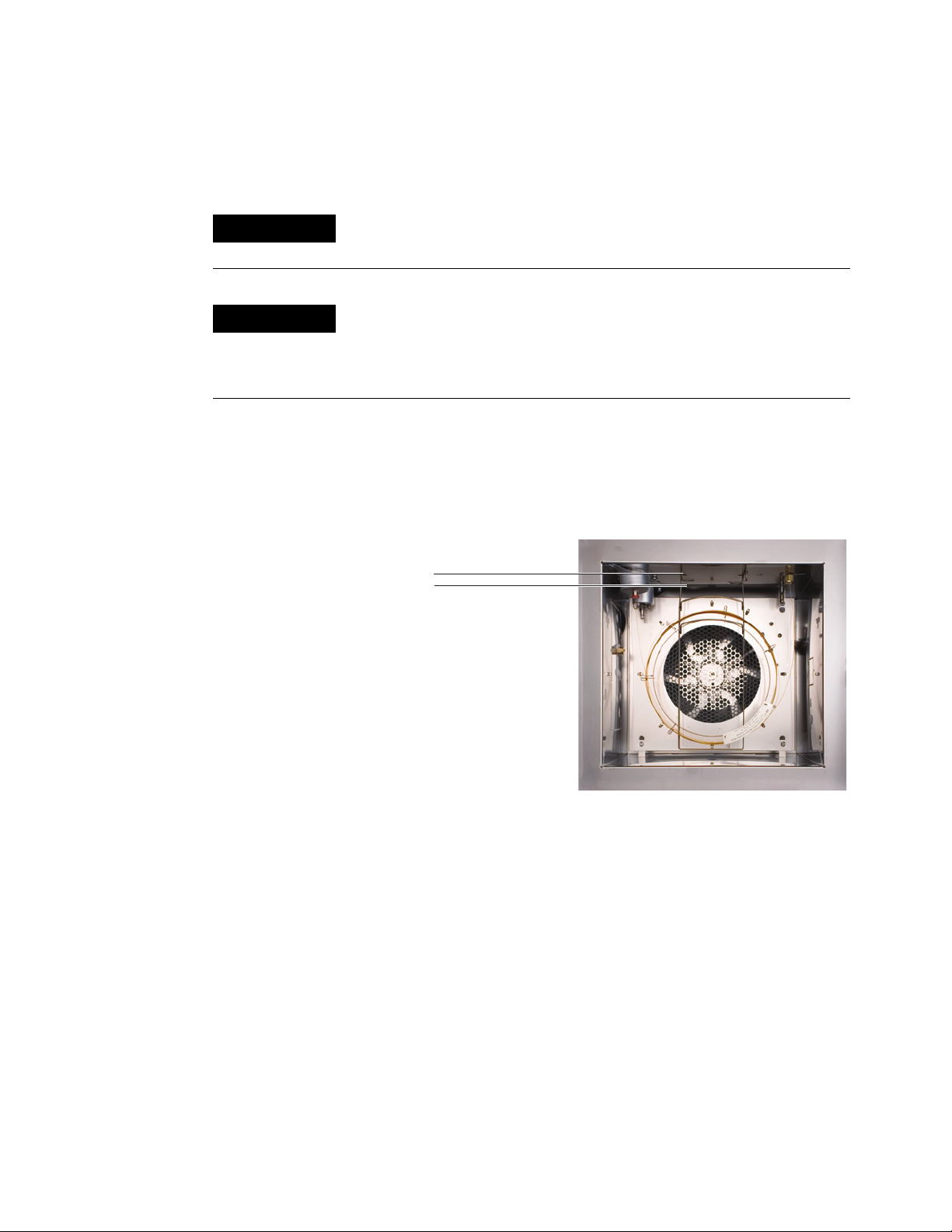
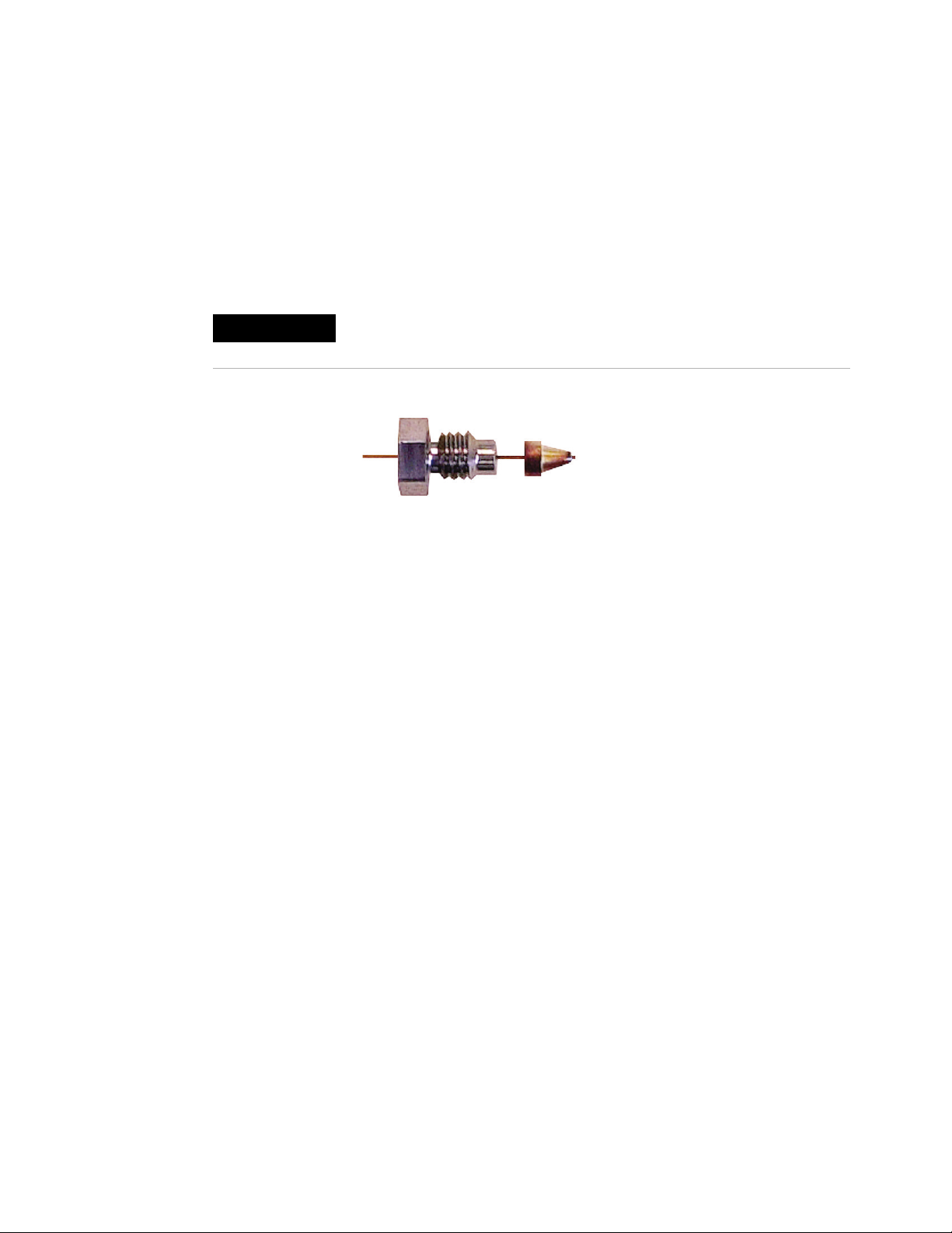
To Replace the Filter in the Split Vent Line
1 Gather the following:
• New filter cartridge. (See “Consumables and Parts for the
Split/Splitless Inlet” on page 32.)
• T-20 Torx screwdriver
2 Prepare the inlets for maintenance. See “Preparing the GC
for Maintenance” on page 15.
WARNING
WARNING
Be careful! The oven and/or inlet may be hot enough to cause
burns. If either is hot, wear heat-resistant gloves to protect your
hands.
The split vent trap may contain residual amounts of any samples
or other chemicals you have injected into the GC. Follow your
company’s safety procedures for handling these types of
substances while replacing the trap filter cartridge.
3 Remove the plastic pneumatics cover (top, back of GC).
4 Lift the filter trap assembly from the mounting bracket and
unscrew the filter trap assembly.
5 Remove the old filter cartridge and two O-rings.
6 Verify the new O-rings are seated properly on the new filter
cartridge.
7 Install the new filter cartridge then reassemble the trap.
8 Place the filter trap assembly in the mounting bracket.
9 Fully tighten the split vent front weldment onto the trap.
10 Check for leaks.
11 Restore the analytical method.
48 Maintaining Your GC
Page 49

To Clean the Split/Splitless Inlet
1 Gather the following:
• Replacement septum (See “Consumables and Parts for the
Split/Splitless Inlet” on page 32.)
• Replacement liner
• Replacement O-ring
• Replacement gold seal
• Replacement washer
• Solvent that will clean the type of deposits in your inlet
• Compressed, filtered, dry air or nitrogen
• Beaker
• Cleaning brushes—The FID cleaning kit (part number
9301-0985) contains appropriate brushes
Maintaining the Split/Splitless Inlet 3
WARNING
CAUTION
• Lint-free gloves
2 Prepare the inlets for maintenance. See “Preparing the GC
for Maintenance” on page 15.
Be careful! The oven and/or inlet may be hot enough to cause
burns. If the inlet is hot, wear heat-resistant gloves to protect your
hands.
3 Remove the inlet liner. (See “To Change the Liner and O-Ring
on the Split/Splitless Inlet” on page 44.)
4 Disconnect the column from the inlet.
5 Remove the reducing nut and gold seal. (See “To Replace the
Gold Seal on the Split/Splitless Inlet” on page 46.)
6 Place a beaker in the oven under the inlet to catch the
solvent.
Wear clean, lint-free gloves to prevent contamination of parts with
dirt and skin oils.
7 Soak a cleaning brush in the solvent and scrub the inside of
the inlet weldment. Repeat 10 times.
8 Rinse the inlet with the solvent.
9 Blow the inside of the inlet dry with compressed air or
nitrogen.
Maintaining Your GC 49
Page 50

3 Maintaining the Split/Splitless Inlet
10
Install the gold seal and reducing nut.
11 Install the liner and O-ring.
12 Install the column. (See “To Install a Capillary Column with
the Split/Splitless Inlet” on page 36.)
13 Check for leaks.
14 Bakeout contaminants. (See “To Bakeout Contaminants from
the Split/Splitless Inlet” on page 51.)
15 Restore the analytical method.
50 Maintaining Your GC
Page 51

Maintaining the Split/Splitless Inlet 3
To Bakeout Contaminants from the Split/Splitless Inlet
1 Put the inlet into split mode.
2 Set the column flow to the normal operating value, or set the
capillary column gas velocity to 30 cm/s.
3 Set the inlet split vent flow to 200 mL/min.
4 Purge the column with carrier flow for at least 10 minutes
before heating the oven.
5 If the column is attached to the detector, set the detector
25 °C above normal operating temperature.
WARNING
Be careful! The oven, inlet, and/or detector may be hot enough to
cause burns. If they are hot, wear heat-resistant gloves to protect
your hands.
If the column is not attached to the detector, cap the detector
fitting.
6 Set the inlet temperature to 300 °C or 25 °C above the
normal operating temperature to bakeout contaminants from
the inlet, mostly through the split vent.
7 Set the column oven 25 °C above the GC method final oven
temperature to bake contaminants from the column. Do not
exceed the column manufacturer’s maximum temperature
limit.
8 Bakeout for 30 minutes or until the detector baseline is free
of contamination peaks.
Maintaining Your GC 51
Page 52

3 Maintaining the Split/Splitless Inlet
52 Maintaining Your GC
Page 53

Agilent 6890 Gas Chromatograph
Maintaining Your GC
4
Maintaining the Purged Packed Inlet
Consumables and Parts for the Purged Packed Inlet 54
Exploded Parts View of the Purged Packed Inlet 57
To Install a Capillary Column with the Purged Packed Inlet 58
To Change the Septum on the Purged Packed Inlet 62
To Clean the Septum Seat in the Purged Packed Inlet 64
To Install an Adapter on the Purged Packed Inlet 66
To Change the O-Ring on the Purged Packed Inlet 68
To Change the Glass Liner on the Purged Packed Inlet 69
To Install an Insulation Cup on the Purged Packed Inlet 71
To Clean the Purged Packed Inlet 72
To Bakeout Contaminants from the Purged Packed Inlet 74
To Install a Packed Metal Column 75
To Install a Packed Column Adapter on a Detector Fitting 77
To Install a Packed Glass Column 79
To Condition a Packed Column 82
To Install Ferrules on a Packed Metal Column 84
Agilent Technologies
53
Page 54

4 Maintaining the Purged Packed Inlet
Consumables and Parts for the Purged Packed Inlet
See the Agilent catalog for consumables and supplies for a more
complete listing, or visit the Agilent Web site for the latest
information (www.agilent.com/chem/supplies).
Tab le 7 Purged packed inlet parts
Description Part number/quantity
Preventative maintenance kit 5188-6498
Purged packed glass liners and column adapters
Glass liner 5080-8732 (25/pack) or
0.53-mm column adapter 19244-80540
1/8-inch column adapter 19243-80530
5181-3382 deactivated
(5/pack)
1/4-inch column adapter 19243-80540
Recommended septa and O-rings for the purged packed inlet
11-mm solid septum, low-bleed, red 5181-1263 (50/pk)
11-mm septum with partial through-hole,
low-bleed, red
11-mm septum, low-bleed, gray 5080-8896 (50/pk)
Merlin Microseal septum (30 psi) 5181-8815
11-mm high-temperature silicone septum
(350 °C and higher)
Viton O-ring (Top insert weldment) 5080-8898 (12/pk)
5181-3383 (50/pk)
5182-0739 (50/pk)
Tab le 8 Nuts and ferrules for packed columns
Description Typical use Part number/quantity
1/8-inch id Swagelok
stainless steel nut, front
ferrule, back ferrule
1/8-inch id Swagelok
brass nut, front ferrule,
back ferrule
1/8-inch column 5080-8751 (20 each/pk)
1/8-inch column 5080-8750 (20 each/pk)
1/8-inch id Vespel/
graphite ferrule
54 Maintaining Your GC
1/8-inch column 0100-1332 (10/pk)
Page 55

Maintaining the Purged Packed Inlet 4
Tab le 8 Nuts and ferrules for packed columns (continued)
Description Typical use Part number/quantity
1/8-inch id
brass tubing nut
1/4-inch id Swagelok
stainless steel nut, front
ferrule, back ferrule
1/4-inch id Swagelok
brass nut, front ferrule,
back ferrule
1/4-inch id Vespel/
graphite ferrule
1/4-inch id
brass tubing nut
1/8-inch column 5180-4103 (10/pk)
1/4-inch column 5080-8753 (20 each/pk)
1/4-inch column 5080-8752 (20 each/pk)
Inlet/detector
liner/adapters
1/4-inch column
1/4-inch column 5180-4105 (10/pk)
5080-8774 (10/pk)
Tab le 9 Nuts, ferrules, and hardware for capillary columns
Column id (mm) Description Typical use Part number/quantity
.530 Ferrule, Vespel/graphite,
0.8-mm id
Ferrule, graphite, 1.0-mm id 0.53-mm capillary columns 5080-8773 (10/pk)
0.45-mm and 0.53-mm capillary
columns
5062-3512 (10/pk)
Column nut, finger-tight (for
0.53-mm columns)
.320 Ferrule, Vespel/graphite,
0.5-mm id
Ferrule, graphite, 0.5-mm id 0.1-mm, 0.2-mm, 0.25-mm, and
Column nut, finger-tight (for
.100- to .320-mm columns)
.250 Ferrule, Vespel/graphite,
0.4-mm id
Ferrule, graphite, 0.5-mm id 0.1-mm, 0.2-mm, 0.25-mm, and
Column nut, finger-tight (for
.100- to .320-mm columns)
.100 and .200 Ferrule, Vespel/graphite,
0.37-mm id
Ferrule, Vespel/graphite,
0.4-mm id
Connect column to inlet or detector 5020-8293
0.32-mm capillary columns 5062-3514 (10/pk)
5080-8853 (10/pk)
0.32-mm capillary columns
Connect column to inlet or detector 5020-8292
0.1-mm, 0.2-mm, and 0.25-mm
capillary columns
0.32-mm capillary columns
Connect column to inlet or detector 5020-8292
0.1-mm and 0.2-mm capillary
columns
0.1-mm, 0.2-mm, and 0.25-mm
capillary columns
5181-3323 (10/pk)
5080-8853 (10/pk)
5062-3516 (10/pk)
5181-3323 (10/pk)
Maintaining Your GC 55
Page 56

4 Maintaining the Purged Packed Inlet
Tab le 9 Nuts, ferrules, and hardware for capillary columns (continued)
Column id (mm) Description Typical use Part number/quantity
Ferrule, graphite, 0.5-mm id 0.1-mm, 0.2-mm, 0.25-mm, and
0.32-mm capillary columns
Column nut, finger-tight (for
.100- to .320-mm columns)
All Ferrule, no-hole Testing 5181-3308 (10/pk)
Capillary column blanking nut Testing–use with any ferrule 5020-8294
Column nut, universal Connect column to inlet or detector 5181-8830 (2/pk)
Column cutter, ceramic wafer Cutting capillary columns 5181-8836 (4/pk)
Connect column to inlet or detector 5020-8292
5080-8853 (10/pk)
56 Maintaining Your GC
Page 57

Exploded Parts View of the Purged Packed Inlet
Maintaining the Purged Packed Inlet 4
Merlin cap
Merlin Microseal
Top insert weldment
O-ring
Glass liner
Ferrule
Septum nut
Septum
Adapter nut
Adapter
Insulation
Insulation cup
Ferrule
Column nut
Maintaining Your GC 57
Page 58

4 Maintaining the Purged Packed Inlet
To Install a Capillary Column with the Purged Packed Inlet
1 Gather the following:
• Column
• Ferrule (See “Consumables and Parts for the Purged
Packed Inlet” on page 54.)
• Column nut
• Glass liner
• Viton O-ring
• 0.53-mm column adapter
• Septum
• 1/4-inch wrench
• Metric ruler
• Lint-free gloves
WARNING
WARNING
CAUTION
2 Prepare the inlet for maintenance. See “Preparing the GC for
Maintenance” on page 15.
Be careful! The oven and/or inlet may be hot enough to cause
burns. If either is hot, wear heat-resistant gloves to protect your
hands.
Wear safety glasses to protect your eyes from flying particles
while handling, cutting, or installing glass or fused silica capillary
columns. Use care in handling these columns to prevent puncture
wounds.
3 Install a 0.53-mm column adapter. (See “To Install an
Adapter on the Purged Packed Inlet” on page 66.)
Wear clean, lint-free gloves to prevent contamination of parts with
dirt and skin oils.
4 Install a new Viton O-ring. (See “To Change the O-Ring on the
Purged Packed Inlet” on page 68.)
5 Place a septum, capillary column nut, and ferrule on the
column.
58 Maintaining Your GC
Page 59

Maintaining the Purged Packed Inlet 4
Ferrule
Column nut
Septum
6 Score the column using a glass scribing tool. The score must
be square to ensure a clean break.
7 Break off the column end by supporting it against the column
cutter opposite the scribe. Inspect the end with a magnifying
loupe to make certain there are no burrs or jagged edges.
8 Wipe the column walls with a tissue dampened with
isopropanol to remove fingerprints and dust.
9 Position the column so it extends 1 to 2 mm above the end of
the ferrule. Slide the septum up the column to hold the
column nut at this fixed position.
1%2 mm
Maintaining Your GC 59
Page 60

4 Maintaining the Purged Packed Inlet
10
Thread the column nut into the inlet adapter but do not
tighten.
11 Adjust the column position so that the septum is even with
the bottom of the column nut. Finger-tighten the column nut
until it begins to grip the column.
12 Tighten the column nut an additional 1/4 to 1/2 turn with a
wrench so that the column cannot be pulled from the fitting
with gentle pressure.
13 Configure the new column.
14 Condition the column per the manufacturer’s
recommendation. (See “To Condition a Capillary Column” on
page 20.)
15 Install the column into the detector. See:
• “To Install a Capillary Column in the FID” on page 155
• “To Install a Capillary Column in the TCD” on page 182
• “To Install a Capillary Column in the uECD” on page 198
• “To Install a Capillary Column Adapter in the FPD” on
page 233
• “To Install a Capillary Column in the NPD” on page 214
16 After the column is installed at both inlet and detector,
establish a flow of carrier gas and purge as recommended by
the column manufacturer.
17 Restore the analytical method.
• For FPD, immediately turn off the flame.
• For NPD, immediately set the bead voltage to 0.0.
18 After the GC becomes ready, wait 10 minutes then ignite the
detector flame or adjust offset on the NPD bead.
60 Maintaining Your GC
Page 61

Maintaining the Purged Packed Inlet 4
WARNING
Be careful! The oven, inlet, and/or detector may be hot enough to
cause burns. If they are hot, wear heat-resistant gloves to protect
your hands.
19
Allow the oven, inlet, and detector to equilibrate at operating
temperature, then retighten the fittings.
Maintaining Your GC 61
Page 62

4 Maintaining the Purged Packed Inlet
To Change the Septum on the Purged Packed Inlet
1 Gather the following:
• Replacement septum (See “Consumables and Parts for the
Purged Packed Inlet” on page 54.)
• Septum nut wrench
• 0- or 00-grade steel wool (optional)
• Tweezers
2 Prepare the inlet for maintenance. See “Preparing the GC for
Maintenance” on page 15.
WARNING
Be careful! The oven and/or inlet may be hot enough to cause
burns. If either is hot, wear heat-resistant gloves to protect your
hands.
3 Remove the septum retainer nut or Merlin cap.
4 Use tweezers to remove the septum or Merlin Microseal from
the retainer nut. Do not gouge or scratch the interior of the
septum head.
Septum retainer nut
Septum
5 Firmly press the new septum or Merlin Microseal into the
fitting. The metal parts side of the Merlin Microseal should
face down (toward the oven).
62 Maintaining Your GC
Page 63

Maintaining the Purged Packed Inlet 4
Merlin Microseal and cap
CAUTION
Standard septum
Replace the septum retainer nut or Merlin cap and
6
finger-tighten. Tighten the septum retainer nut until the
C-ring is about 1 mm above the nut.
Overtightening the septum nut can cause contamination.
1 mm
7 Restore the analytical method.
Maintaining Your GC 63
Page 64

4 Maintaining the Purged Packed Inlet
To Clean the Septum Seat in the Purged Packed Inlet
1 Gather the following:
• Replacement septum (See “Consumables and Parts for the
Purged Packed Inlet” on page 54.)
• Septum nut wrench
• 0- or 00-grade steel wool (optional)
• Tweezers
• Compressed, filtered, dry air or nitrogen
• Ultrasonic cleaning bath
• Lint-free gloves
2 Prepare the inlets for maintenance. See “Preparing the GC
for Maintenance” on page 15.
WARNING
CAUTION
Be careful! The oven and/or inlet may be hot enough to cause
burns. If the inlet is hot, wear heat-resistant gloves to protect your
hands.
3 Remove the septum retainer nut or Merlin cap.
4 Loosen the top insert weldment and remove.
Wear clean, lint-free gloves to prevent contamination of parts with
dirt and skin oils.
5 Use tweezers to remove the septum or Merlin Microseal from
the top insert weldment. Do not gouge or scratch the interior
of the septum head.
6 Scrub the residue from the top insert weldment and septum
nut with a small piece of rolled-up steel wool and tweezers.
Ultrasonically clean the retainer nut and top insert
weldment.
7 Use compressed air or nitrogen to blow away the pieces of
steel wool and septum.
8 Wearing gloves, inspect the O-ring and replace, if necessary.
(See “To Change the O-Ring on the Purged Packed Inlet” on
page 68.)
9 Install the top insert weldment and hand-tighten firmly.
64 Maintaining Your GC
Page 65

Maintaining the Purged Packed Inlet 4
10
Firmly press the new septum or Merlin Microseal into the
fitting.
11 Install the septum retainer nut or Merlin cap and
finger-tighten. Tighten the septum retainer nut until the
C-ring is about 1 mm above the nut.
CAUTION
Overtightening the septum nut can cause contamination.
1 mm
12 Restore the analytical method.
Maintaining Your GC 65
Page 66

4 Maintaining the Purged Packed Inlet
To Install an Adapter on the Purged Packed Inlet
1 Gather the following:
• Brass tubing nut (See “Consumables and Parts for the
Purged Packed Inlet” on page 54.)
• Adapter (0.53 mm, 1/8-inch packed, or 1/4-inch packed)
• 7/16-inch and 9/16-inch wrench
• Vespel/graphite ferrule
• Methanol
• Lint-free gloves
2 Prepare the inlet for maintenance. See “Preparing the GC for
Maintenance” on page 15.
WARNING
CAUTION
Be careful! The oven and/or inlet may be hot enough to cause
burns. If the inlet is hot, wear heat-resistant gloves to protect your
hands.
Wear clean, lint-free gloves to prevent contamination of parts with
dirt and skin oils.
3 Clean the end of the adapter with a lint-free cloth and
methanol to remove contamination such as fingerprints.
4 Place the tubing nut and Vespel/graphite ferrule on the
adapter.
66 Maintaining Your GC
Page 67

Maintaining the Purged Packed Inlet 4
Inlet fitting
Ferrule
Tubing nut
Adapter
Insert the adapter straight into the inlet base as far as
5
possible.
6 Hold the adapter in this position and finger-tighten the nut.
7 Tighten an additional 1/4 turn with a wrench.
Maintaining Your GC 67
Page 68

4 Maintaining the Purged Packed Inlet
To Change the O-Ring on the Purged Packed Inlet
1 Gather the following:
• Replacement O-ring (See “Consumables and Parts for the
Purged Packed Inlet” on page 54.)
• Septum nut wrench
• Tweezers
• Lint-free gloves
2 Prepare the inlet for maintenance. See “Preparing the GC for
Maintenance” on page 15.
WARNING
CAUTION
Be careful! The oven and/or inlet may be hot enough to cause
burns. If the inlet is hot, wear heat-resistant gloves to protect your
hands.
3 Loosen the top insert weldment to remove the top portion of
the inlet.
Wear clean, lint-free gloves to prevent contamination of parts with
dirt and skin oils.
4 Use tweezers to remove the old O-ring.
5 Insert a new O-ring.
6 Install and tighten the top insert weldment.
7 Restore the analytical method.
68 Maintaining Your GC
Page 69

Maintaining the Purged Packed Inlet 4
To Change the Glass Liner on the Purged Packed Inlet
1 Gather the following:
• Replacement glass liner (See “Consumables and Parts for
the Purged Packed Inlet” on page 54.)
• 9/16-inch wrench
• Lint-free gloves
2 Prepare the inlet for maintenance. See “Preparing the GC for
Maintenance” on page 15.
Top insert weldment
Flared end
Glass liner
WARNING
Be careful! The oven and/or inlet may be hot enough to cause
burns. If the inlet is hot, wear heat-resistant gloves to protect your
hands.
3 Loosen the top insert weldment to remove the top portion of
the inlet.
4 Use a thin wire or wood splint to carefully lift and remove
the old glass liner.
CAUTION
Wear clean, lint-free gloves to prevent contamination of parts with
dirt and skin oils.
Maintaining Your GC 69
Page 70

4 Maintaining the Purged Packed Inlet
5
Wearing gloves, inspect the O-ring and replace, if necessary.
(See “To Change the O-Ring on the Purged Packed Inlet” on
page 68.)
6 Wearing gloves, grasp the flared end (top) of the replacement
glass liner with tweezers and install it in the inlet. If the glass
liner does not seat properly because a capillary column is
installed, remove the column, install the glass liner, and
replace the column. (See “To Install a Capillary Column with
the Purged Packed Inlet” on page 58.)
7 Install the top insert weldment and hand-tighten firmly.
8 Restore the analytical method.
70 Maintaining Your GC
Page 71

Maintaining the Purged Packed Inlet 4
To Install an Insulation Cup on the Purged Packed Inlet
1 Gather the following:
• No-hole ferrule
• Column nut
2 Install a plug (for example, a column nut with no-hole
ferrule) in the inlet capillary adapter.
3 Push the cup spring to the right. Slide the cup over the inlet
fitting so that the insulation at the top of the cup is flush
against the oven roof.
4 Place the spring into the groove in the inlet liner. Remove the
column nut and no-hole ferrule.
Maintaining Your GC 71
Page 72

4 Maintaining the Purged Packed Inlet
To Clean the Purged Packed Inlet
1 Gather the following:
• Replacement O-ring (See “Consumables and Parts for the
Purged Packed Inlet” on page 54.)
• Replacement glass liner
• Replacement septum
• Solvent that will clean the type of deposits in your inlet
• Compressed, filtered, dry air or nitrogen
• Beaker
• Cleaning brushes—The FID cleaning kit (part number
9301-0985) contains appropriate brushes
• Lint-free gloves
2 Prepare the inlets for maintenance. See “Preparing the GC
for Maintenance” on page 15.
WARNING
CAUTION
Be careful! The oven and/or inlet may be hot enough to cause
burns. If the inlet is hot, wear heat-resistant gloves to protect your
hands.
3 Remove the column.
4 Remove the septum nut and septum.
5 Remove the top insert weldment.
6 Remove the glass liner and O-ring.
7 If used, remove the adapter.
8 Ultrasonically clean the septum nut, top insert weldment,
and adapter (if used) in a suitable solvent.
9 Place a beaker in the oven under the inlet to catch the
solvent.
Wear clean, lint-free gloves to prevent contamination of parts with
dirt and skin oils.
10 Soak a cleaning brush with the solvent and vigorously scrub
the interior walls of the inlet.
11 Blow the inside of the inlet dry with compressed air or
nitrogen.
72 Maintaining Your GC
Page 73

Maintaining the Purged Packed Inlet 4
12
Install the adapter, if used. (See “To Install an Adapter on the
Purged Packed Inlet” on page 66.)
13 Install the glass liner and O-ring. (See “To Change the Glass
Liner on the Purged Packed Inlet” on page 69.)
14 Install the top insert weldment and finger-tighten.
15 Install the septum and septum nut. (See “To Change the
Septum on the Purged Packed Inlet” on page 62.)
16 Attach the column. (See “To Install a Capillary Column with
the Purged Packed Inlet” on page 58.)
17 Check for leaks.
18 Restore the analytical method.
Maintaining Your GC 73
Page 74

4 Maintaining the Purged Packed Inlet
To Bakeout Contaminants from the Purged Packed Inlet
1 Set the column flow to the normal operating value, or set the
capillary column gas velocity to 30 cm/s.
2 Purge the column with carrier flow for at least 10 minutes
before heating the oven.
3 If the column is attached to the detector, set the detector
25 °C above normal operating temperature.
If the column is not attached to the detector, cap the detector
fitting.
4 Set the inlet temperature to 300 °C or 25 °C above the
normal operating temperature.
5 Set the column oven 25 °C above the GC method final oven
temperature to bake contaminants out of the inlet. Do not
exceed the column manufacturer’s maximum temperature
limit.
6 Bakeout for 30 minutes or until the detector baseline is free
of contamination peaks.
74 Maintaining Your GC
Page 75

To Install a Packed Metal Column
1 Gather the following:
• 7/16-inch, 9/16-inch, and 1/2-inch wrenches
• Lint-free gloves
2 Prepare the GC for maintenance. See “Preparing the GC for
Maintenance” on page 15.
3 Prepare the packed metal column. (See “To Install Ferrules
on a Packed Metal Column” on page 84.)
Maintaining the Purged Packed Inlet 4
WARNING
CAUTION
Be careful! The oven, inlet, and/or detector may be hot enough to
cause burns. If the oven, inlet, or detector is hot, wear gloves to
protect your hands.
4 Install the 1/8-inch or 1/4-inch packed column inlet adapter,
if necessary. (See “To Install an Adapter on the Purged
Packed Inlet” on page 66.)
Wear clean, lint-free gloves to prevent contamination of parts with
dirt and skin oils.
5 Attach the column to the inlet adapter. Finger-tighten the
nut.
6 Tighten the nut an additional 1/4 turn with a wrench (for a
1/8-inch column) or an additional 3/4 turn (for a 1/4-inch
column).
Use two wrenches, one on the column nut and the other on
the adapter, to prevent the adapter from rotating.
7 Press [Config] [Col 1] or [Config] [Col 2] and enter 0.00 in either
Length or Diameter, and identify the inlet and detector to
which the column is attached.
=
WARNING
Do not use hydrogen as the carrier for conditioning! It could vent
into the oven and present an explosion hazard.
8 Condition the column, if necessary. (See “To Condition a
Packed Column” on page 82.)
Maintaining Your GC 75
Page 76

4 Maintaining the Purged Packed Inlet
9
Load the GC maintenance method and wait for the GC to
become ready.
WARNING
Be careful! The oven, inlet, and/or detector may be hot enough to
cause burns. If the oven, inlet, or detector is hot, wear gloves to
protect your hands.
10 If required, install the detector adapter. (See “To Install a
Packed Column Adapter on a Detector Fitting” on page 77.)
11 Attach the column to the detector or detector adapter.
Finger-tighten the nut.
12 Tighten the nut an additional 1/4 turn with a wrench (for a
1/8-inch column) or an additional 3/4 turn (for a 1/4-inch
column).
13 Establish a flow of carrier gas and purge as recommended by
the packing manufacturer. Generally:
• 20 to 30 mL/min for 2-mm id glass or 1/8-inch od metal
columns
• 50 to 60 mL/min for 4-mm id glass or 1/4-inch od metal
columns
14 Restore the analytical method.
• For FPD, immediately turn off the flame.
WARNING
• For NPD, immediately set the bead voltage to 0.0.
15 After the GC becomes ready, wait 10 minutes then ignite the
detector flame or adjust offset on the NPD bead.
Be careful! The oven, inlet, and/or detector may be hot enough to
cause burns. If they are hot, wear heat-resistant gloves to protect
your hands.
16 Allow the oven, inlet, and detector to equilibrate at operating
temperature, then retighten the fittings.
76 Maintaining Your GC
Page 77

Maintaining the Purged Packed Inlet 4
To Install a Packed Column Adapter on a Detector Fitting
1 Gather the following:
• 7/16-inch, 9/16-inch, and 1/2-inch wrenches
• Vespel/graphite ferrule (See “Consumables and Parts for
the Purged Packed Inlet” on page 54.)
• Brass column nut
• Lint-free gloves
• Adapter. Select the appropriate adapter from one of the
parts lists shown below:
“Consumables and Parts for the FID” on page 146 (Packed
columns can only be installed on an adaptable FID.)
“Consumables and Parts for the TCD” on page 180
“Consumables and Parts for the NPD” on page 206
WARNING
CAUTION
“Consumables and Parts for the FPD” on page 230
2 Prepare the column and oven for maintenance. See
“Preparing the GC for Maintenance” on page 15.
Be careful! The detector may be hot enough to cause burns. If the
detector is hot, wear gloves to protect your hands.
Wear clean, lint-free gloves to prevent contamination of parts with
dirt and skin oils.
3 Assemble a nut and a ferrule onto the adapter.
4 Insert the adapter straight into the detector base as far as
possible.
Maintaining Your GC 77
Page 78

4 Maintaining the Purged Packed Inlet
Hold the adapter in this position and finger-tighten the nut.
5
6 Tighten an additional 1/4 turn with a wrench (for a 1/8-inch
column) or an additional 3/4 turn (for a 1/4-inch column).
78 Maintaining Your GC
Page 79

To Install a Packed Glass Column
1 Gather the following:
• 9/16-inch wrench
• Two 1/4-inch brass nuts (See “Consumables and Parts for
the Purged Packed Inlet” on page 54.)
• Two 1/4-inch Vespel/graphite ferrules
• Lint-free gloves
2 Prepare the GC for maintenance. See “Preparing the GC for
Maintenance” on page 15.
Maintaining the Purged Packed Inlet 4
WARNING
CAUTION
Be careful! The oven, inlet, and/or detector may be hot enough to
cause burns. If the oven, inlet, or detector is hot, wear gloves to
protect your hands.
Wear clean, lint-free gloves to prevent contamination of parts with
dirt and skin oils.
3 Assemble a brass nut and Vespel/graphite ferrule on each
end of the column.
Glass columns must be simultaneously inserted into the inlet
and detector and installed parallel to the oven door. When
conditioning the column, do not attach the column to the
detector.
4 If conditioning the column, insert the column into the purged
packed inlet until it bottoms. Withdraw the column 1 to
2 mm. Finger-tighten the inlet column nut. (See “To
Condition a Packed Column” on page 82.)
CAUTION
Overtightening the column nut or forcing it to bottom in either the
inlet or detector may shatter the column.
Maintaining Your GC 79
Page 80

4 Maintaining the Purged Packed Inlet
WARNING
Tighten the inlet column nut 1/4 turn with a wrench.
5
=
Do not use hydrogen as the carrier for conditioning! It could vent
into the oven and present an explosion hazard.
6 After conditioning, remove the column from the inlet.
7 Simultaneously insert the column into the inlet and detector
fittings but do not force it. It may be necessary to start the long
end of the column in the inlet at an angle to clear the oven floor.
CAUTION
8 Withdraw the column 1 to 2 mm from both the inlet and
detector. Finger-tighten both column nuts.
Overtightening the column nut or forcing it to bottom in either the
inlet or detector may shatter the column.
9 Tighten both column nuts 1/4 turn with a wrench.
10 Press [Config] [Column #], enter 0.00 in either Length or
Diameter, and identify the inlet and detector to which the
column is connected.
11 Establish a flow of carrier gas and purge as recommended by
the packing manufacturer. Generally:
• 20 to 30 mL/min for 2-mm id glass or 1/8-inch od metal
columns
• 50 to 60 mL/min for 4-mm id glass or 1/4-inch od metal
columns
12 Restore the analytical method.
• For FPD, immediately turn off the flame.
• For NPD, immediately set the bead voltage to 0.0.
80 Maintaining Your GC
Page 81

Maintaining the Purged Packed Inlet 4
13
After the GC becomes ready, wait 10 minutes then ignite the
detector flame or adjust offset on the NPD bead.
WARNING
Be careful! The oven, inlet, and/or detector may be hot enough to
cause burns. If they are hot, wear heat-resistant gloves to protect
your hands.
14 Allow the oven, inlet, and detector to equilibrate at operating
temperature, then retighten the fittings.
Maintaining Your GC 81
Page 82

4 Maintaining the Purged Packed Inlet
To Condition a Packed Column
1 Gather the following:
• Capillary adapter, column nut, and no-hole ferrule (for
• Two 7/16-inch wrenches
• 1/4-inch open-end wrench
• Lint-free gloves
=
WARNING
Do not use hydrogen as the carrier for conditioning! It could vent
into the oven and present an explosion hazard.
2 Prepare the column and oven for maintenance. See
“Preparing the GC for Maintenance” on page 15.
FID and NPD), or 1/8-inch Swagelok cap (for TCD and
FPD)
WARNING
CAUTION
Be careful! The oven, inlet, and/or detector may be hot enough to
cause burns. If the oven, inlet, or detector is hot, wear gloves to
protect your hands.
Wear clean, lint-free gloves to prevent contamination of parts with
dirt and skin oils.
3 Install the proper liner in the inlet and attach the column.
(See “To Install a Packed Metal Column” on page 75.)
4 Cap the detector(s) fittings with the capillary adapter,
no-hole ferrule and column nut (FID and NPD) or
1/8-inch cap (FPD and TCD).
5 Enter a column flow as recommended by the packing
manufacturer or an appropriate flow as follows:
• 20 to 30 mL/min for 2-mm id glass or 1/8-inch od metal
columns
• 50 to 60 mL/min for 4-mm id glass or 1/4-inch od metal
columns
6 Raise the oven temperature slowly to the conditioning
temperature for the column. The conditioning temperature is
never higher than the maximum temperature limit for the
column; 30 °C less than the maximum is usually sufficient.
82 Maintaining Your GC
Page 83

Maintaining the Purged Packed Inlet 4
7
Continue conditioning overnight at the final temperature.
Cool the oven to room temperature with carrier flow on.
8 Attach the column to the detector and maintain established
flow. (See “To Install a Packed Metal Column” on page 75.)
Maintaining Your GC 83
Page 84

4 Maintaining the Purged Packed Inlet
To Install Ferrules on a Packed Metal Column
1 Gather the following:
• Wrenches
• Stainless steel male Swagelok fitting, 1/4- or 1/8-inch od
• Brass Swagelok nut and ferrule set (See “Consumables
and Parts for the Purged Packed Inlet” on page 54.)
• Lint-free gloves
2 Verify that the column end is cut square and is free of burns
and deformation.
3 Secure the fitting in a bench vise.
CAUTION
Wear clean, lint-free gloves to prevent contamination of parts with
dirt and skin oils.
4 Assemble a Swagelok nut and ferrules onto the column.
Front ferrule
Back ferrule
Column nut
5 Fully insert the column into the vise-held fitting, then
withdraw 1–2 mm. Finger-tighten the nut.
6 Tighten the nut an additional 3/4 turn with a wrench (for a
1/8-inch column) or an additional 1-1/4 turn (for a 1/4-inch
column).
7 Unscrew the column nut from the vise-held fitting and
remove the column. Ferrules should now be set in place on
the column with the column end correctly positioned.
84 Maintaining Your GC
Page 85

Agilent 6890 Gas Chromatograph
Maintaining Your GC
5
Maintaining the COC Inlet
Consumables and Parts for the COC Inlet 86
Exploded Parts View of the COC Inlet 89
To Install a Capillary Column with the COC Inlet 90
To Check the Needle-to-Column Size on the COC Inlet 93
To Change a Septum on the COC Inlet 94
To Install an Insert on the COC Inlet 96
To Clean the COC Inlet 98
To Replace the Needle Support Assembly in a 7683B Injector 100
To Replace a Needle in a Syringe 103
To Replace the Fused Silica Needle in a Syringe for the COC Inlet 104
To Bakeout Contaminants from the COC Inlet 106
Agilent Technologies
85
Page 86

5 Maintaining the COC Inlet
Consumables and Parts for the COC Inlet
See the Agilent catalog for consumables and supplies for a more
complete listing, or visit the Agilent Web site for the latest
information (www.agilent.com/chem/supplies).
Tab le 1 0 Recommended septum nut and inserts for injections onto
0.53-mm columns
Column type Part number
Insert, fused silica, 0.53-mm id 19245-20580 (no rings)
Insert, aluminum-clad, 0.53-mm id 19245-20780 (4 rings)
Septum nut, 530 µm G1545-80520
Needle support assembly, 530 µm, for 7683B
injector
G2913-60977
Tab le 1 1 Recommended parts for injections onto 0.25-mm and 0.32-mm
columns
Column type Part number
Insert, fused silica, 0.32-mm id 19245-20525 (5 rings)
Insert, 0.25-mm id 19245-20515 (6 rings)
Septum nut, 250/320 µm 19245-80521
Syringe barrel, removable needle, 5 µL 5182-0836
Needle, 250 µm (3/pk) 5182-0833
Needle, 320 µm (3/pk) 5182-0831
Needle support assembly,250/320 µm, for 7683B
injector
G2913-60978
Tab le 1 2 Recommended parts for injections onto 0.2-mm columns
Description Part number/quantity
Insert, fused silica, 0.20-mm id 19245-20510
Cooling tower assembly 19230-80625
Syringe barrel, for fused silica needle, 10 µL 9301-0658
Replacement needles, fused silica, 0.18 mm 19091-63000 (6/pk)
Replacement Teflon ferrule for fused silica syringe 0100-1389
Removable stainless steel needle syringe, 10 µL 5182-9633
86 Maintaining Your GC
Page 87

Maintaining the COC Inlet 5
Tab le 1 2 Recommended parts for injections onto 0.2-mm columns
Description Part number/quantity
Replacement stainless steel needles, 0.23 mm 5182-9645 (3/pk)
Tab le 1 3 Recommended septa for the COC inlet
Description Part number/quantity
For 0.53-mm and 0.25/0.32-mm septum nuts
5-mm solid septum for manual and automatic
injection
5-mm long-life septum 5183-4762 (50/pk)
5-mm advanced green septum 5183-4760 (50/pk)
5-mm, high-temperature, low-bleed septum 5183-4758 (50/pk)
5-mm through-hole septum for automatic
injection
For the duckbill septum
Duckbill septum for manual injection only (must
use cooling tower with duckbill)
5181-1261
5181-1260 (25/pk)
19245-40050 (10/pk)
Tab le 1 4 Nuts, ferrules, and hardware for capillary columns
Column id (mm) Description Typical use Part number/quantity
.530 Ferrule, Vespel/graphite,
0.8-mm id
Ferrule, graphite, 1.0-mm id 0.53-mm capillary columns 5080-8773 (10/pk)
Column nut, finger-tight (for
0.53-mm columns)
0.45-mm and 0.53-mm capillary
columns
Connect column to inlet or detector 5020-8293
5062-3512 (10/pk)
.320 Ferrule, Vespel/graphite,
0.5-mm id
Ferrule, graphite, 0.5-mm id 0.1-mm, 0.2-mm, 0.25-mm, and
Column nut, finger-tight (for
.100- to .320-mm columns)
.250 Ferrule, Vespel/graphite,
0.4-mm id
Ferrule, graphite, 0.5-mm id 0.1-mm, 0.2-mm, 0.25-mm, and
Maintaining Your GC 87
0.32-mm capillary columns 5062-3514 (10/pk)
5080-8853 (10/pk)
0.32-mm capillary columns
Connect column to inlet or detector 5020-8292
0.1-mm, 0.2-mm, and 0.25-mm
capillary columns
0.32-mm capillary columns
5181-3323 (10/pk)
5080-8853 (10/pk)
Page 88

5 Maintaining the COC Inlet
Tab le 1 4 Nuts, ferrules, and hardware for capillary columns (continued)
Column id (mm) Description Typical use Part number/quantity
Column nut, finger-tight (for
.100- to .320-mm columns)
.100 and .200 Ferrule, Vespel/graphite,
0.37-mm id
Ferrule, Vespel/graphite,
0.4-mm id
Ferrule, graphite, 0.5-mm id 0.1-mm, 0.2-mm, 0.25-mm, and
Column nut, finger-tight (for
.100- to .320-mm columns)
All Ferrule, no-hole Testing 5181-3308 (10/pk)
Capillary column blanking nut Testing–use with any ferrule 5020-8294
Column nut, universal Connect column to inlet or detector 5181-8830 (2/pk)
Column cutter, ceramic wafer Cutting capillary columns 5181-8836 (4/pk)
Connect column to inlet or detector 5020-8292
0.1-mm and 0.2-mm capillary
columns
0.1-mm, 0.2-mm, and 0.25-mm
capillary columns
0.32-mm capillary columns
Connect column to inlet or detector 5020-8292
5062-3516 (10/pk)
5181-3323 (10/pk)
5080-8853 (10/pk)
88 Maintaining Your GC
Page 89

Exploded Parts View of the COC Inlet
Septum nut
(0.53 mm)
Septum nut
(0.25-mm and 0.32-mm
columns)
Maintaining the COC Inlet 5
Cooling tower assembly
Septum
Spring
Insert
Duckbill septum
Ferrule
Column nut
Maintaining Your GC 89
Page 90

5 Maintaining the COC Inlet
To Install a Capillary Column with the COC Inlet
1 Gather the following:
• Column nut and ferrule. (See “Consumables and Parts for
the COC Inlet” on page 86.)
• Column cutter
• 1/4-inch and 5/16-inch wrenches
• Lint-free gloves
2 Prepare the inlet for maintenance. See “Preparing the GC for
Maintenance” on page 15.
WARNING
WARNING
CAUTION
Be careful! The oven and/or inlet may be hot enough to cause
burns. If either is hot, wear heat-resistant gloves to protect your
hands.
Wear safety glasses to protect your eyes from flying particles
while handling, cutting, or installing glass or fused silica capillary
columns. Use care in handling these columns to prevent puncture
wounds.
Wear clean, lint-free gloves to prevent contamination of parts with
dirt and skin oils.
3 Before installing the column, be sure the correct insert is
installed for the needle and column. (See “To Install an Insert
on the COC Inlet” on page 96.)
4 Place a capillary column nut and ferrule on the column.
Ferrule
Column nut
5 Score the column using a glass scribing tool. The score must
be square to ensure a clean break.
90 Maintaining Your GC
Page 91

Maintaining the COC Inlet 5
Break off the column end by supporting it against the column
6
cutter opposite the scribe. Inspect the end with a magnifying
loupe to make certain there are no burrs or jagged edges.
7 Wipe the column walls with a tissue dampened with
isopropanol to remove fingerprints and dust.
8 Gently insert the column into the inlet until it bottoms.
9 Insert the column nut into the inlet fitting and finger-tighten.
WARNING
To avoid bending the inlet, always use two wrenches. Use a
5/16-inch wrench to support the inlet while tightening the column
nut with a 1/4-inch wrench.
10 Tighten the column nut an additional 1/4 turn with a wrench
or until the column does not move.
11 If using an automatic injection system with a 0.25-mm or
0.32-mm column, verify that the column installation by
manually pushing the syringe into the inlet.
12 Configure the new column.
13 Condition the column per the manufacturer’s
recommendation. (See “To Condition a Capillary Column” on
page 20.)
Maintaining Your GC 91
Page 92

5 Maintaining the COC Inlet
14
Install the column into the detector. See:
• “To Install a Capillary Column in the FID” on page 155
• “To Install a Capillary Column in the TCD” on page 182
• “To Install a Capillary Column in the uECD” on page 198
• “To Install a Capillary Column Adapter in the FPD” on
page 233
• “To Install a Capillary Column in the NPD” on page 214
15 After the column is installed at both inlet and detector,
establish a flow of carrier gas and purge as recommended by
the column manufacturer.
16 Restore the analytical method.
• For FPD, immediately turn off the flame.
• For NPD, immediately set the bead voltage to 0.0.
17 After the GC becomes ready, wait 10 minutes then ignite the
detector flame or adjust offset on the NPD bead.
WARNING
Be careful! The oven, inlet, and/or detector may be hot enough to
cause burns. If they are hot, wear heat-resistant gloves to protect
your hands.
18 Allow the oven, inlet, and detector to equilibrate at operating
temperature, then retighten the fittings.
92 Maintaining Your GC
Page 93

To Check the Needle-to-Column Size on the COC Inlet
1 Gather the following:
• Insert (See “Consumables and Parts for the COC Inlet” on
page 86.)
• Syringe needle
2 Prepare the inlet for maintenance. See “Preparing the GC for
Maintenance” on page 15.
Maintaining the COC Inlet 5
WARNING
WARNING
Be careful! The oven and/or inlet may be hot enough to cause
burns. If either is hot, wear heat-resistant gloves to protect your
hands.
Wear safety glasses to protect your eyes from flying particles
while handling, cutting, or installing glass or fused silica capillary
columns. Use care in handling these columns to prevent puncture
wounds.
3 Check the needle-to-column size to make certain that the
needle fits in the column.
4 Identify the correct insert for the column size. (See
“Consumables and Parts for the COC Inlet” on page 86.) Use
the insert that is the same size as the syringe needle to verify
that the column you plan to use is the correct size.
5 Insert the column into one end of the insert.
Syringe
Insert
Column
6 Insert the syringe needle through the other end of the insert
and into the column. If the needle cannot pass easily into the
column, reverse the insert to try the needle and column in
the other end.
Maintaining Your GC 93
Page 94

5 Maintaining the COC Inlet
To Change a Septum on the COC Inlet
1 Gather the following:
• Replacement septum. (See “Consumables and Parts for
the COC Inlet” on page 86.)
• Tweezers
• A thin wire (0.2-inch diameter) for removing septum from
inlet
• Lint-free gloves
2 Prepare the inlet for maintenance. See “Preparing the GC for
Maintenance” on page 15.
WARNING
CAUTION
Be careful! The oven and/or inlet may be hot enough to cause
burns. If either is hot, wear heat-resistant gloves to protect your
hands.
Wear clean, lint-free gloves to prevent contamination of parts with
dirt and skin oils.
3 Replace the septum.
• If you are using a septum nut, grasp the knurling and
unscrew. Remove the old septum with tweezers. Use
tweezers to install a new septum. Push the septum into
the septum nut until properly seated. Firmly tighten the
nut.
For 250/320-µm
automated injections
For 530-µm automated
injections
94 Maintaining Your GC
Page 95

Maintaining the COC Inlet 5
• If you are using a cooling tower, grasp the three rings and
unscrew. The spring and duckbill septum may pop out of
the inlet when you remove the cooling tower. Be careful
not to lose them. If they do not pop out, use a thin wire to
remove them from the inlet. Insert the replacement
duckbill septum into the spring and place in the inlet.
Reattach the cooling tower assembly, then finger-tighten.
For manual 200-µm injections with
fused silica needle
4 Before making an injection, check the alignment of the entire
assembly using the proper size syringe.
5 Restore the analytical method.
Maintaining Your GC 95
Page 96

5 Maintaining the COC Inlet
To Install an Insert on the COC Inlet
1 Gather the following:
• Lint-free gloves
• Replacement insert. (See “Consumables and Parts for the
COC Inlet” on page 86.)
2 Prepare the inlet for maintenance. See “Preparing the GC for
Maintenance” on page 15.
WARNING
CAUTION
Be careful! The oven and/or inlet may be hot enough to cause
burns. If either is hot, wear heat-resistant gloves to protect your
hands.
Wear clean, lint-free gloves to prevent contamination of parts with
dirt and skin oils.
3 Remove the column from the inlet.
4 Locate the septum nut or cooling tower assembly at the top
of the inlet and remove it. If the septum remains in the
septum nut, do not remove it unless you want to change it. If
necessary, replace the existing septum or duckbill with a new
one. (See “To Change a Septum on the COC Inlet” on
page 94.)
5 Remove the spring from the inlet with an extraction wire and
set it aside. Be careful not to lose or damage it because you
will use the spring to keep the new insert in position.
6 Remove the existing insert from the inlet by gently pushing it
out from below with a wire or piece of column. Store the
insert for possible later use.
96 Maintaining Your GC
Page 97

Maintaining the COC Inlet 5
7
Check that the insert is the correct size for both the needle
and column. (See “To Check the Needle-to-Column Size on
the COC Inlet” on page 93.)
8 Lower the new insert straight into the inlet from the top.
9 Install the spring on top of the insert.
10 Install the septum and septum nut or duckbill septum and
cooling tower assembly and finger-tighten.
11 Install the column. (See “To Install a Capillary Column with
the COC Inlet” on page 90.)
Maintaining Your GC 97
Page 98

5 Maintaining the COC Inlet
To Clean the COC Inlet
1 Gather the following:
• 1/4-inch and 5/16-inch wrenches
• Cleansing bath
• Aqueous detergent
• Distilled water
• Methanol
• Compressed, filtered, dry air or nitrogen
• Lint-free gloves
2 Prepare the inlet for maintenance. See “Preparing the GC for
Maintenance” on page 15.
WARNING
WARNING
CAUTION
Be careful! The oven and/or inlet may be hot enough to cause
burns. If either is hot, wear heat-resistant gloves to protect your
hands.
Wear safety glasses to protect your eyes from flying particles
while handling, cutting, or installing glass or fused silica capillary
columns. Use care in handling these columns to prevent puncture
wounds.
Wear clean, lint-free gloves to prevent contamination of parts with
dirt and skin oils.
3 Remove the column.
4 Remove the septum nut or cooling tower and then remove the
septum.
5 Remove the existing insert from the inlet by gently pushing it
out from below with a wire or piece of column. Store the
insert for possible later use.
98 Maintaining Your GC
Page 99

Maintaining the COC Inlet 5
6
Fill an ultrasonic cleansing bath with aqueous detergent and
place the spring and insert into it. Sonicate for 1 minute.
7 Drain the aqueous detergent and fill the bath with distilled
water. Sonicate for 1 minute.
8 Remove the spring and insert from the bath and rinse
thoroughly with water and methanol.
9 Dry the spring and insert with compressed air or nitrogen.
10 Install the insert. (See “To Install an Insert on the COC Inlet”
on page 96.)
11 Install the column. (See “To Install a Capillary Column with
the COC Inlet” on page 90.)
Maintaining Your GC 99
Page 100

5 Maintaining the COC Inlet
To Replace the Needle Support Assembly in a 7683B Injector
1 Gather a 7683B needle support assembly for injections onto
530-µm or 250/320-µm columns.
250 µm/320 µm
(G2913-60978)
2 Remove all vials and bottles from the turret, and disconnect
530 µm
(standard, G2913-60978)
the injector cable from the GC.
3 Open the injector door.
4 Remove the syringe.
5 With your finger under the shaft near the bearing on the
needle support assembly, pull gently to release the bearing
from the bearing clip in the syringe carriage.
100 Maintaining Your GC
 Loading...