

Page 1

OPERATING GUIDE
GPIB DC POWER SUPPLIES
Agilent Technologies Models
664xA, 665xA, 667xA, 668xA, and 669xA
sA
Agilent Part No. 5964-8267 Printed in Malaysia
Microfiche Part No. 5964-8268 January, 2005
Page 2

Certification
Agilent Technologies certifies that this product met its published specifications at time of shipment from the factory.
Agilent Technologies further certifies that its calibration measurements are traceable to the United States National
Institute of Standards and Technology, to the extent allowed by the Institute's calibration facility, and to the calibration
facilities of other International Standards Organization members.
Warranty
This Agilent Technologies hardware product is warranted against defects in material and workmanship for a period of one
year from date of delivery. Agilent Technologies software and firmware products, which are designated by Agilent
Technologies for use with a hardware product and when properly installed on that hardware product, are warranted not to
fail to execute their programming instructions due to defects in material and workmanship for a period of 90 days from date
of delivery. During the warranty period Agilent Technologies will, at its option, either repair or replace products which
prove to be defective. Agilent Technologies does not warrant that the operation of the software, firmware, or hardware shall
be uninterrupted or error free.
For warranty service, with the exception of warranty options, this product must be returned to a service facility designated
by Agilent Technologies. Customer shall prepay shipping charges by (and shall pay all duty and taxes) for products returned
to Agilent Technologies for warranty service. Except for products returned to Customer from another country, Agilent
Technologies shall pay for return of products to Customer.
Warranty services outside the country of initial purchase are included in Agilent Technologies' product price, only if
Customer pays Agilent Technologies international prices (defined as destination local currency price, or U.S. or Geneva
Export price).
If Agilent Technologies is unable, within a reasonable time to repair or replace any product to condition as warranted, the
Customer shall be entitled to a refund of the purchase price upon return of the product to Agilent Technologies.
Limitation of Warranty
The foregoing warranty shall not apply to defects resulting from improper or inadequate maintenance by the Customer,
Customer-supplied software or interfacing, unauthorized modification or misuse, operation outside of the environmental
specifications for the product, or improper site preparation and maintenance. NO OTHER WARRANTY IS EXPRESSED
OR IMPLIED. Agilent Technologies SPECIFICALLY DISCLAIMS THE IMPLIED WARRANTIES OF
MERCHANTABILITY AND FITNESS FOR A PARTICULAR PURPOSE.
Exclusive Remedies
THE REMEDIES PROVIDED HEREIN ARE THE CUSTOMER'S SOLE AND EXCLUSIVE REMEDIES. AGILENT
TECHNOLOGIES SHALL NOT BE LIABLE FOR ANY DIRECT, INDIRECT, SPECIAL, INCIDENTAL, OR
CONSEQUENTIAL DAMAGES, WHETHER BASED ON CONTRACT, TORT, OR ANY OTHER LEGAL THEORY.
Assistance
The above statements apply only to the standard product warranty. Warranty options, extended support contracts, product
maintenance agreements and customer assistance agreements are also available. Contact your nearest Agilent
Technologies Sales and Service offices for further information on Agilent Technologies' full line of Support Programs.
2
Page 3

Safety Summary
The following general safety precautions must be observed during all phases of operation, service, and repair of
this instrument. Failure to comply with these precautions or with specific warnings elsewhere in this manual
violates safety standards of design, manufacture, and intended use of the instrument. Agilent Technologies
assumes no liability for the customer's failure to comply with these requirements.
GENERAL
Any LEDs used in this product are Class 1 LEDs as per IEC 825-l.
This ISM device complies with Canadian ICES-001. Cet appareil ISM est conforme à la norme NMB-001 du Canada.
ENVIRONMENTAL CONDITIONS
With the exceptions noted, all instruments are intended for indoor use in an installation category II
environment. They are designed to operate at a maximum relative humidity of 95% and at altitudes of up to 2000 meters.
Refer to the specifications tables for the ac mains voltage requirements and ambient operating temperature range.
Exceptions: Agilent Technologies Models 6680A, 6681A, 6682A, 6683A, 6684A, 6690A, 6691A and 6692A are intended
for use in an installation category III
1
Category II - Local level for connection to household outlets for 120 V, 230 V, etc.
2
Category III - Distribution level or cases where the reliability and availability of the equipment are subject to special requirements.
2
environment.
BEFORE APPLYING POWER
Verify that the product is set to match the available line voltage and the correct fuse is installed.
GROUND THE INSTRUMENT.
This product is a Safety Class 1 instrument (provided with a protective earth terminal). To minimize shock hazard, the
instrument chassis and cabinet must be connected to an electrical ground. The instrument must be connected to the ac mains
through a three-conductor power cable, with the third wire firmly connected to an electrical ground (safety ground) at the
power outlet. For instruments designed to be hard-wired to the ac power lines (supply mains), connect the protective earth
terminal to a protective conductor before any other connection is made. Any interruption of the protective (grounding)
conductor or disconnection of the protective earth terminal will cause a potential shock hazard that could result in personal
injury. If the instrument is to be energized via an external autotransformer for voltage reduction, be certain that the
autotransformer common terminal is connected to the neutral (earthed pole) of the ac power lines (supply mains).
FUSES
Only fuses with the required rated current, voltage, and specified type (normal blow, time delay, etc.) should be used. Do
not use repaired fuses or short circuited fuseholders. To do so could cause a shock or fire hazard.
DO NOT OPERATE IN AN EXPLOSIVE ATMOSPHERE
Do not operate the instrument in the presence of flammable gases or fumes.
KEEP AWAY FROM LIVE CIRCUITS
Operating personnel must not remove instrument covers. Component replacement and internal adjustments must be made by
qualified service personnel. Do not replace components with power cable connected. Under certain conditions, dangerous
voltages may exist even with the power cable removed. To avoid injuries, always disconnect power, discharge circuits and
remove external voltage sources before touching components.
DO NOT SERVICE OR ADJUST ALONE
Do not attempt internal service or adjustment unless another person, capable of rendering first aid and resuscitation, is
present.
DO NOT EXCEED INPUT RATINGS
This instrument may be equipped with a line filter to reduce electromagnetic interference and must be connected to a
properly grounded receptacle to minimize electric shock hazard. Operation at line voltages or frequencies in excess of those
stated on the data plate may cause leakage currents in excess of 5.0 mA peak.
DO NOT SUBSTITUTE PARTS OR MODIFY INSTRUMENT
Because of the danger of introducing additional hazards, do not install substitute parts or perform any unauthorized
modification to the instrument. Return the instrument to an Agilent Technologies Sales and Service Offices for service and
repair to ensure that safety features are maintained.
Instruments which appear damaged or defective should be made inoperative and secured against unintended operation until
they can be repaired by qualified service personnel.
1
, pollution degree 2
3
Page 4

Safety Symbol Definitions
Symbol Description Symbol Description
Direct current
Alternating current
Both direct and alternating current
Three-phase alternating current
Earth (ground) terminal
Protective earth (ground) terminal
Frame or chassis terminal
Terminal for Neutral conductor on
permanently installed equipment
Terminal is at earth potential(Used for
measurement and control circuits designed to
be operated with one terminal at earth
potential.)
Terminal for Line conductor on permanently installed
equipment
Caution, risk of electric shock
Caution, hot surface
Caution (refer to accompanying documents)
In position of a bi -stable push control
Out position of a bi -stable push control
On (supply)
Off (supply)
Standby (supply). Units with this symbol are not
completely disconnected from ac mains when this switch is
off. To completely disconnect the unit from ac mains,
either disconnect the power cord or have a qualified
electrician install an external switch.
The WARNING sign denotes a hazard. It
calls attention to a procedure, practice, or the like, which, if
not correctly performed or adhered to, could result in
personal injury. Do not proceed beyond a WARNING sign
until the indicated conditions are fully understood and met.
attention to an operating procedure, or the like, which, if not correctly
performed or adhered to, could result in damage to or destruction of part
or all of the product. Do not proceed beyond a CAUTION sign until the
indicated conditions are fully understood and met.
The CAUTION sign denotes a hazard. It calls
Printing History
The edition and current revision of this manual are indicated below. Reprints of this manual containing minor corrections
and updates may have the same printing date. Revised editions are identified by a new printing date. A revised edition
incorporates all new or corrected material since the previous printing date. Changes to the manual occurring between
revisions are covered by change sheets shipped with the m anual. In some cases, the manual change applies only to specific
instruments. Instructions provided on the change sheet will indicate if a particular change applies only to certain
instruments.
Copyright 2001, 2002, 2005 Agilent Technologies Inc. Edition 1 - July, 2001
Update1 - March, 2002
Update2 - January, 2005
This document contains proprietary information protected by copyright. All rights are reserved. No part of this document
may be photocopied, reproduced, or translated into another language without the prior consent of Agilent Technologies.
Information contained in this document is subject to change without notice.
Herstellerbescheinigung
Diese Information steht im Zusammenhang mit den Anforderungen der Maschinenläminformationsverordnung vom 18
Januar 1991. * Schalldruckpegel Lp <70 dB(A) * Am Arbeitsplatz * Normaler Betrieb * Nach EN 27779 (Typprufung).
Manufacturer's Declaration
This statement is provided to comply with the requirements of the German Sound Emission Directive, from 18 January
1991. * Sound Pressure Lp <70 dB(A) *At Operator Position * Normal Operation * According to EN 27779 (Type Test).
4
Page 5

DECLARATION OF CONFORMITY
According to ISO/IEC Guide 22 and CEN/CENELEC EN 45014
Manufacturer’s Name and Address
Responsible Party
Agilent Technologies, Inc. Agilent Technologies (Malaysia) Sdn. Bhd
550 Clark Drive, Suite 101
Budd Lake, New Jersey 07828
USA
Declares under sole responsibility that the product as originally delivered
EMC Information ISM Group 1 Class A Emissions
Safety Information and Conforms to the following safety standards.
This DoC applies to above-listed products placed on the EU market after:
January 1, 2004
Date Bill Darcy/ Regulations Manager
For further information, please contact your local Agilent Technologies sales office, agent or distributor, or
Agilent Technologies Deutschland GmbH, Herrenberger Straβe 130, D71034 Böblingen, Germany
Revision: B.00.00 Issue Date: Created on 11/24/2003 3:23
Alternate Manufacturing Site
Product Names
Model Numbers
Product Options
Complies with the essential requirements of the Low Voltage Directive 73/23/EEC and the EMC
Directive 89/336/EEC (including 93/68/EEC) and carries the CE Marking accordingly.
As detailed in Electromagnetic Compatibility (EMC), Certificate of Conformance Number
Assessed by: Celestica Ltd, Appointed Competent Body
Malaysia Manufacturing
Bayan Lepas Free Industrial Zone, PH III
11900 Penang,
Malaysia
a) Single Output 2,000 Watt System dc Power Supplies
b) Single Output 2,000 Watt Manually Controlled dc Power Supplies
c) Single Output 5,000 Watt System dc Power Supplies
d) Single Output 6,500 Watt System dc Power Supplies
a) 6671A, 6672A 6673A, 6674A, 6675A
b) 6571A, 6572A 6573A, 6574A, 6575A
c) 6680A, 6681A, 6682A, 6683A, 6684A
d) 6690A, 6691A, 6692A
e) E4356A
This declaration covers all options and customized products based on the above
products.
CC/TCF/02/020 based on Technical Construction File (TCF) HPNJ2, dated
June 4, 2002
Westfields House, West Avenue
Kidsgrove, Stoke-on-Trent
Straffordshire, ST7 1TL
United Kingdom
IEC 61010-1:2001 / EN 61010-1:2001
Canada: CSA C22.2 No. 1010.1:1992
UL 61010B-1: 2003
Document No. 6x7y668xA.11.24.doc
PM
5
Page 6

DECLARATION OF CONFORMITY
According to ISO/IEC Guide 22 and CEN/CENELEC EN 45014
Manufacturer’s Name and Address
Responsible Party
Agilent Technologies, Inc. Agilent Technologies (Malaysia) Sdn. Bhd
550 Clark Drive, Suite 101
Budd Lake, New Jersey 07828
USA
Declares under sole responsibility that the product as originally delivered
EMC Information ISM Group 1 Class A Emissions
Safety Information and Conforms to the following safety standards.
This DoC applies to above-listed products placed on the EU market after:
January 1, 2004
Date Bill Darcy/ Regulations Manager
For further information, please contact your local Agilent Technologies sales office, agent or distributor, or
Agilent Technologies Deutschland GmbH, Herrenberger Straβe 130, D71034 Böblingen, Germany
Revision: B.00.00 Issue Date: Created on 11/24/2003 3:26
Alternate Manufacturing Site
Product Names
Model Numbers
Product Options
Complies with the essential requirements of the Low Voltage Directive 73/23/EEC and the EMC
Directive 89/336/EEC (including 93/68/EEC) and carries the CE Marking accordingly.
As detailed in Electromagnetic Compatibility (EMC), Certificate of Conformance Number
Assessed by: Celestica Ltd, Appointed Competent Body
Malaysia Manufacturing
Bayan Lepas Free Industrial Zone, PH III
11900 Penang,
Malaysia
a) Single Output 500 Watt System dc Power Supplies
b) Single Output 500 Watt Manually Controlled dc Power Supplies
c) Single Output 500 Watt System Solar Array Simulator
a) 6651A, 6652A 6653A, 6654A, 6655A
b) 6551A, 6552A 6553A, 6554A, 6555A
c) E4350B, E4351B
This declaration covers all options and customized products based on the above
products.
CC/TCF/00/074 based on Technical Construction File (TCF) HPNJ1, dated
Oct. 27, 1997
Westfields House, West Avenue
Kidsgrove, Stoke-on-Trent
Straffordshire, ST7 1TL
United Kingdom
IEC 61010-1:2001 / EN 61010-1:2001
Canada: CSA C22.2 No. 1010.1:1992
UL 61010B-1: 2003
PM
6x4yA6x5yAE435xA.b.11.24doc.doc
Document No.
6
Page 7

DECLARATION OF CONFORMITY
According to ISO/IEC Guide 22 and CEN/CENELEC EN 45014
Manufacturer’s Name and Address
Responsible Party
Agilent Technologies, Inc. Agilent Technologies (Malaysia) Sdn. Bhd
550 Clark Drive, Suite 101
Budd Lake, New Jersey 07828
USA
Declares under sole responsibility that the product as originally delivered
EMC Information ISM Group 1 Class A Emissions
Safety Information and Conforms to the following safety standards.
This DoC applies to above-listed products placed on the EU market after:
January 1, 2004
Date Bill Darcy/ Regulations Manager
For further information, please contact your local Agilent Technologies sales office, agent or distributor, or
Agilent Technologies Deutschland GmbH, Herrenberger Straβe 130, D71034 Böblingen, Germany
Revision: B.00.00 Issue Date: Created on 11/24/2003 3:26
Alternate Manufacturing Site
Malaysia Manufacturing
Bayan Lepas Free Industrial Zone, PH III
11900 Penang,
Malaysia
Product Names
Model Numbers
Product Options
Complies with the essential requirements of the Low Voltage Directive 73/23/EEC and the EMC
Directive 89/336/EEC (including 93/68/EEC) and carries the CE Marking accordingly.
As detailed in Electromagnetic Compatibility (EMC), Certificate of Conformance Number
Assessed by: Celestica Ltd, Appointed Competent Body
a) Single Output 200 Watt System dc Power Supplies
b) Single Output 200 Watt Manually Controlled dc Power Supplies
a) 6641A, 6642A 6643A, 6644A, 6645A
b) 6541A, 6552A 6543A, 6544A, 6545A
This declaration covers all options and customized products based on the above
products.
CC/TCF/00/074 based on Technical Construction File (TCF) HPNJ1, dated
Oct. 27, 1997
Westfields House, West Avenue
Kidsgrove, Stoke-on-Trent
Straffordshire, ST7 1TL
United Kingdom
IEC 61010-1:2001 / EN 61010-1:2001
Canada: CSA C22.2 No. 1010.1:1992
UL 61010B-1: 2003
PM
6x4yA6x5yAE435xA.a.11.24doc.doc
Document No.
7
Page 8

Table of Contents
Certification 2
Safety Summary 3
Printing History 4
Declarations 5
Table of Contents 8
GENERAL INFORMATION 11
Introduction 11
Safety Considerations 12
Instrument Identification 12
Options 12
Accessories 13
Description 13
Front Panel Programming 14
Remote Programming 14
Analog Programming 14
Output Characteristic 15
General 15
Downprogramming 15
Specifications and Supplemental Characteristics 15
INSTALLATION 43
Inspection 43
Damage 43
Packaging Material 43
Items Supplied 43
Location and Temperature 44
Bench Operation 44
Rack Mounting 44
Temperature Performance 44
Input Power Source 45
Installing the Series 664xA and 665xA Power Cord 45
Installing the Series 667xA Power Cord 45
Installing the Series 668xA Power Cord 47
Installing the Series 669xA Power Cord 48
TURN-ON CHECKOUT 51
Introduction 51
Preliminary Checkout (All Models) 51
Power-On Checkout (All Models) 52
Using the Keypad (All Models) 52
Shifted Keys 52
Backspace Key 52
Output Checkout (All Models) 52
Checking the Voltage Function 53
Checking the Current Function 54
Checking the Save and Recall Functions (All Models) 55
Determining the GPIB Address (All Models) 55
In Case of Trouble 55
Line Fuse 55
Series 664xA and 665xA Supplies 56
Series 667xA Supplies 56
Series 668xA Supplies 57
Series 669xA Supplies 57
Error Messages (All Models) 57
Selftest Errors 57
Power-On Error Messages 57
8
Page 9

Checksum Errors. 58
Runtime Error Messages 58
USER CONNECTIONS 59
Rear Panel Connections (All Models) 59
Load Wire Selection (All Models) 59
Analog Connector (All Models) 60
Digital Connector (All Models) 60
Connecting Series 664xA and 665xA Power Supplies to the Load 61
Output Isolation 61
Load Considerations 61
Local Voltage Sensing 62
Remote Voltage Sensing 63
Connecting One Supply to the Load 64
Connecting Supplies in Auto-Parallel 65
Connecting Supplies in Series 67
External Voltage Control 67
Connecting Series 667xA Power Supplies to the Load 68
Output Isolation 68
Load Considerations 69
Local Voltage Sensing 70
Remote Voltage Sensing 70
Connecting One Power Supply to a Single Load 72
Connecting One Power Supply To Multiple Loads 72
Connecting Supplies in Auto-Parallel 73
Connecting Supplies in Series 74
External Voltage Control 75
Connecting Series 668xA and 669xA Power Supplies to the Load 76
Output Isolation 76
Load Considerations 76
Local Voltage Sensing 77
Remote Voltage Sensing 77
Connecting One Power Supply to a Single Load 79
Connecting One Power Supply to Multiple Loads 79
Connecting Supplies in Auto-Parallel 80
Connecting Supplies in Series 81
External Voltage Control 82
Controller Connections 83
Stand-Alone Connections 83
Linked Connections 83
FRONT PANEL OPERATION 85
Introduction 85
Getting Acquainted 85
Programming the Output 88
Establishing Initial Conditions 88
Programming Voltage 89
Programming Overvoltage Protection 89
Programming Current 90
Programming Overcurrent Protection 91
CV Mode vs. CC Mode 91
Unregulated Operation 92
Saving and Recalling Operating States 92
Turn-On Conditions 92
Setting the GPIB Address 93
Types of Power Supply GPIB Addresses 93
Changing the Power Supply GPIB Address 93
CALIBRATION 95
9
Page 10

Introduction 95
Equipment Required 95
General Procedure 95
Parameters Calibrated 95
Test Setup 96
Front Panel Calibration 96
Entering the Calibration Values 96
Saving the Calibration Constants 96
Disabling the Calibration Mode 96
Changing the Calibration Password 96
Recovering From Calibration Problems 99
Calibration Error Messages 99
Calibration Over the GPIB 100
Calibration Language Dictionary 100
CAL:CURR 100
CAL:CURR:LEV 100
CAL:CURR:MON (Series 668xA/669xA only) 101
CAL:PASS 101
CAL:SAVE 101
CAL:STAT 101
CAL:VOLT 102
CAL:VOLT:LEV 102
CAL:VOLT:PROT 102
Agilent BASIC Calibration Program 102
OPERATION VERIFICATION 105
Introduction 105
Test Equipment Required 105
List of Equipment 105
Current Monitoring Resistor 105
Performing the Tests 107
General Measurement Techniques 107
Programming the Power Supply 107
Order of Tests 107
Turn-on Checkout 107
Voltage Programming and Readback Accuracy 107
Current Programming and Readback Accuracy 108
LINE VOLTAGE CONVERSION 119
Series 664xA and 665xA Power Supplies 119
Series 667xA Power Supplies 120
Series 668xA/669xA Power Supplies 121
DIGITAL PORT FUNCTIONS 123
Digital Connector 123
Fault/Inhibit Operation 123
Changing the Port Configuration 126
Digital I/O Operation 126
Relay Link Operation 127
CURRENT LOOP COMPENSATION (SERIES 668XA ONLY) 129
Introduction 129
Function of Loop Compensation 129
Setting The Loop Compensation Switch 132
USING AGILENT 668XA/669XA SERIES POWER SUPPLIES IN AUTOPARALLEL 133
Introduction 133
OUTPUT BUS BAR OPTIONS 135
Option 601 Installation 135
Option 602 Installation 136
INDEX 137
10
Page 11

1
General Information
Introduction
Two guides are shipped with your power supply - an Operating Guide (this document) and a Programming Guide. You will
find information on the following tasks in these guides:
Quick Document Orientation
Topic Location
Calibrating the power supply Appendix A - this guide
Compatibility programming language Appendix B - Programming Guide
Configuring the digital port Appendix D - this guide
Line voltage:
Connecting ac power source Chapter 2 - this guide
Converting the ac source voltage Appendix B - this guide
Source current, frequency, and power ratings Chapter 1- this guide
Operator replaceable parts Chapter 1- this guide
Operator troubleshooting Chapter 3 - this guide
Output impedance characteristics Chapter 1- this guide
Power supply accessories Chapter 1- this guide
Power supply operating characteristics Chapter 1- this guide
Power supply options Chapter 1- this guide
Power supply performance specifications Chapter 1- this guide
Programming
discrete fault inhibit (DFI) operation Chapter 4 - Programming Guide
from the analog port Chapter 4 - this guide
from the front panel Chapter 5 - this guide
over the GPIB Chapter 2 - Programming Guide
remote inhibit (RI) operation Chapter 4 - Programming Guide
status registers Chapter 4 - Programming Guide
Quick operating checkout (without load) Chapter 3 - this guide
Rack mounting Chapter 2 - this guide
SCPI programming language Chapter 3 - Programming Guide
Wiring
analog programming port Chapter 4 - this guide
discrete fault indicator (DFI) operation Appendix D - this guide
digital port Appendix D - this guide
GPIB controller Chapter 4 - this guide
load or loads Chapter 4 - this guide
local sensing Chapter 4 - this guide
remote inhibit (RI) operation Chapter 4 - this guide
remote sensing Chapter 4 - this guide
1
See the Table of Contents for complete list of topics.
1
General Information 11
Page 12

Safety Considerations
This power supply is a Safety Class 1 instrument, which means it has a protective earth terminal. That terminal must be
connected to earth ground through a power source equipped with a 3-wire ground receptacle. Refer to the Safety Summary
page at the beginning of this guide for general safety information. Before installation or operation, check the power supply
and review this guide for safety warnings and instructions. Safety warnings for specific procedures are located at
appropriate places in the guide. warning
Instrument Identification
The power supply is identified by a unique serial number that provides the following information:
US = The letter indicates the country of manufacture, where US = USA; MY = Malaysia.
33430177 = The first four digits indicate the year and week of manufacture or last significant design change. Add 1960 to
the first two digits to determine the year. For example, 32=1992, 33=1993, etc. The third and forth digits
specify the week of the year (43 = the 43rd week). The last four digits is the number assigned to each unit.
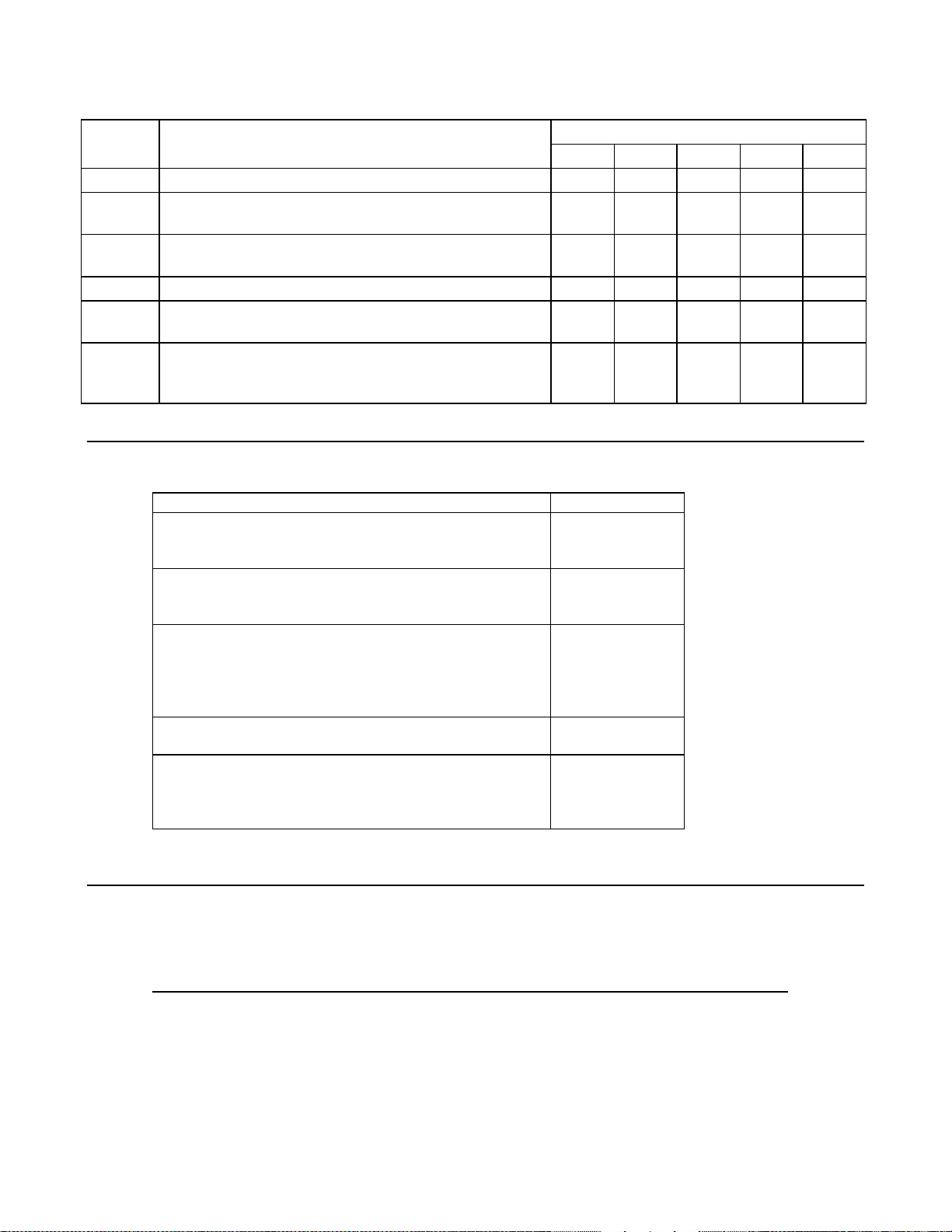
Options
Option Description Used with Agilent Series
664xA 665xA 667xA 668xA 669xA
100
120
220
240
200
230
208
400
601
602
831
832
834
841
842
843
844
861
862
Input power 87-106 Vac, with power cord x x
Input power 104-127 Vac, with power cord x x
Input power 191-233 Vac, with power cord x x
Input power 209-250 Vac, with power cord x x
Input power 174-220 Vac, without power cord x
Input power 191-250 Vac, without power cord x
Input power 180-235 Vac, 3-phase, without power cord x x
Input power 360-440 Vac, 3-phase, without power cord x x
Output connector kit required for bench applications x x
Bus bar spacers for paralleling power supplies x x
Power cord, 12 AWG, UL listed, CSA certified, without plug x
2
Power cord, 4mm
Power cord, 10 AWG, UL listed, CSA certified, without plug x
Power cord, 12 AWG, UL listed, CSA certified, with NEMA
6-20P 20A/250V plug
Power cord, 4mm
Power cord, 12 AWG, UL listed, CSA certified, with JIS
C8303 25A/250V plug
Power cord, 10 AWG, UL listed, CSA certified, with NEMA
L6-30P-30A/250V locking plug
Power cord, 10 AWG, 4-wire, 300V, 25A, 90°C, UL listed,
CSA certified, without plug
Power cord, 8 AWG, 4-wire, 300 V, 35A, 90°C, UL listed,
CSA certified, without plug
Power cord, 2.5mm
without plug
, harmonized, without plug x
x
2
, harmonized, with IEC309 32A/220V plug x
x
x
x
x
2
, 4-wire, 450V, 20A, 70°C, harmonized,
x x
General Information 12
Page 13
List of Options (continued)
Option Description Used with Agilent Series
664xA 665xA 667xA 668xA 669xA
908
909
Rack mount kit (Agilent 5062-3974) x
Rack mount kit (Agilent 5062-3977)
Support rails (E3663AC) are required.
Rack mount kit (Agilent 5062-3977 & 5062-3974)
Support rails (E3663AC) are required.
Rack mount kit with handles (Agilent 5062-3975) x
Rack mount kit with handles (Agilent 5062-3983)
Support rails (E3663AC) are required.
Rack mount kit with handles (Agilent 5062-3983 &
5062-3974)
Support rails (E3663AC) are required.
x x
x x
x x
x x
Accessories
Description Agilent No.
Fuse replacement kit for Series 668xA
16 AM for 360-440 Vac, 3-phase line 5060-3512
30 AM for 180-235 Vac, 3-phase line 5060-3513
Fuse replacement kit for Series 669xA
16 AM for 360-440 Vac, 3-phase line 2110-1077
30 AM for 180-235 Vac, 3-phase line 2110-1078
GPIB cable (all models)
0.5 meters (1.6 ft) 10833D
1.0 meter (3.3 ft) 10833A
2.0 meters (6.6 ft) 10833B
4.0 meters ( 13 .2 ft) 10833C
Serial link cable (all models)
2.0 meters (6.6 ft) 5080-2148
Slide mount kit
heavy duty, for Series 667xA/668xA/669xA 1494-0058
standard, for Series 665xA 1494-0059
standard, for Series 664xA 1494-0060
Description
These units form a family of unipolar, GPIB programmable power supplies organized as follows:
Family Power Agilent Models
Series 664xA 200 W 6641A, 6642A, 6643A, 6644A, 6645A
Series 665xA 500 W 6651A, 6652A, 6653A, 6654A, 6655A
Series 667xA 2000 W 6671A, 6672A, 6673A, 6674A, 6675A
Series 668xA 5000 W 6680A, 6681A, 6682A, 6683A, 6684A
Series 669xA 6670 W 6690A, 6691A, 6692A
Each power supply is programmable locally from the front panel or remotely via a rear-panel analog control port.
General Information 13
Page 14

Operational features include:
■ Constant voltage (CV) or constant current (CC) output over the rated output range.
■ Built-in overvoltage (OV), overcurrent (OC), and overtemperature (OT) protection.
■ Automatic turn-on selftest.
■ Pushbutton nonvolatile storage and recall of up to 5 operating states (4 in Series 668xA/669xA supplies).
■ Local or remote sensing of output voltage.
■ Auto-parallel operation for increased total current.
■ Series operation for increased total voltage.
■ Analog input for remote programming of voltage and current.
■ Voltage output for external monitoring of output current.
■ User calibration from the front panel.
Front Panel Programming
The front panel has both rotary (RPG) and keypad controls for setting the output voltage and current. The panel display
provides digital readouts of the output voltage and current. Other front panel controls permit:
■ Enabling or disabling the output.
■ Setting the overvoltage protection (OVP) trip voltage.
■ Enabling or disabling the overcurrent protection (OCP) feature.
■ Saving and recalling operating states.
■ Setting the GPIB address.
■ Reading GPIB error message codes.
■ Calibrating the power supply, including changing the calibration protection password.
Remote Programming
The power supply may be remotely programmed via the GPIB bus and/or from an analog input port. GPIB programming is
with SCPI (Standard Commands for Programmable Instruments) commands that make the power supply programs
compatible with those of other GPIB instruments. (A software-controlled Compatibility Mode also permits programming in
the command set of the Agilent 6030xA Autoranging Series.) In addition to control functions, SCPI programming permits
writing to the front panel LCD and complete calibration functions. Power supply status registers permit remote monitoring
of the following conditions:
■ Overvoltage, overcurrent, overtemperature, and unregulated states.
■ Operating mode (constant voltage or constant current).
■ State of the RI (remote inhibit) input signal.
■ Power-on status (PON).
■ Status of the output queue (QYE).
■ Pending triggers (WTG).
■ GPIB interface programming errors (CME, DDE, and EXE).
■ Calibration state (enabled or disabled).
The status registers can be programmed to generate an output fault signal (FLT) upon the occurrence of one or more
selected status events.
Analog Programming
The power supply has an analog port for remote programming. The output voltage and/or current of the power supply may
be controlled by individual dc programming voltages applied to this port. The port also provides a monitor output that
supplies a dc voltage proportional to the output current.
General Information 14
Page 15

Output Characteristic
General
The power supply can operate in either CV (constant voltage) or CC (constant current) over its voltage and current ratings
(see Table 1-l). The operating locus is shown by the Output Characteristic Curve in Table 1-2. The operating point is
determined by the voltage setting (V
Point 1 is defined by the load line cutting the operating locus in the constant-voltage region. This region defines the CV
mode. Point 2 is defined by the load line cutting the operating locus in the constant-current region. This region defines the
CC mode.
), the current setting (Is), and the load impedance. Two operating points are shown.
s
Downprogramming
The power supply can sink current for more rapid down programming in the CV mode. For Series 664xA and 665xA
supplies, this capability is defined by the second quadrant area (-I
sink about 20% of their maximum rated positive output current. For Series 667xA, 668xA, and 669xA power supplies, this
is an uncharacterized current-sinking area that provides a limited downprogramming capability.
) of the Output Characteristic Curve. These supplies can
s
Specifications and Supplemental Characteristics
Tables 1-1 through 1-4 list the specifications and supplemental characteristics for the Series 664xA, 665xA, 667xA, 668xA,
and 669xA power supplies. The organization is as follows:
Series Specifications Characteristics
6641A-6645A Table l-la Table l-lb
6651A-6655A Table 1-2a Table 1-2b
6671A-6675A Table 1-3a Table 1-3b
6680A-6684A Table 1-4a Table 1-4b
6690A-6692A Table 1-5a Table 1-5b
Specifications are performance parameters warranted over the specified temperature range.
Supplemental Characteristics are not warranted but are descriptions of performance determined either by design or type
testing.
General Information 15
Page 16

Table 1-1a. Performance Specifications for Series 664xA
1
Parameter Agilent Model Number
6641A 6642A 6643A 6644A 6645A
Output Ratings
Voltage:
Current:@ 40°°°°C
Current:@ 50°°°°C
Current:@ 55°°°°C
0 - 8 V 0 - 20 V 0 - 35 V 0 - 60 V 0 - 120 V
0 - 20 A 0 - 10 A 0 - 6 A 0 - 3.5 A 0 - 1.5 A
0 - 18 A 0 - 9 A 0 - 5.4 A 0 - 3.2 A 0 - 1.4 A
0 - 17 A 0 - 8.5 A 0 - 5.1 A 0 - 3.0 A 0 -1.4 A
Programming Accuracy (@ 25 ± 5 °C)
Voltage: 2 0.06% +
Current: 0.l5 % +
5 mV
26 mA 13 mA
10 mV 15 mV
6.7 mA
26 mV 51 mV
4.1 mA
1.7 mA
Ripple & Noise (from 20 Hz to 20 MHz with outputs ungrounded, or with either output terminal grounded)
Constant Voltage: rms
Constant Voltage: p-p
Constant Current: rms
300 µV 300 µV 400 µV 500 µV 700 µV
3 mV 3 mV 4 mV 5 mV 7 mV
10 mA
5 mA 3 mA 1.5 mA 1 mA
Readback Accuracy (from front panel or over GPIB with respect to actual output @ 25 ±:5 °C)
Voltage: 2 0.07% +
+Current 0.15% +
-Current 0.35% +
6 mV 15 mV 25 mV 40 mV 80 mV
18 mA 9.1 mA 5 mA 3 mA 1.3 mA
40 mA 20 mA 12 mA 6.8 mA 2.9 mA
Load Regulation (change in output voltage or current for any load change within ratings)
Voltage
Current:
1 mV 2 mV 3 mV 4 mV 5 mV
1 mA 0.5 mA 0.25 mA 0.25 mA 0.25 mA
Line Regulation (change in output voltage or current for any line change within ratings
Voltage:
Current:
0.5 mV 0.5 mV 1 mV 1 mV 2 mV
1 mA 0.5 mA 0.25 mA 0.25 mA 0.25 mA
Transient Response Time (for the output voltage to recover to its previous level (within 0.1% of the rated voltage or
20 mV, whichever is greater) following any step change in load current up to 50% of the rated current.
< 100 µs
AC Input Ratings (selectable via internal switching - see Appendix C)
Nominal line voltage:
Frequency:
Output Terminal Isolation
Notes:
2
3
1
For Supplemental Characteristics, see Table 1-1b.
Specification may degrade slightly when unit is subjected to an RF field ≥ 3V/meter.
For 230Vac operation, unit is internally set to 240Vac
100, 120, 220, 240 Vac (-13%, +6 %)
230 Vac
±240 Vdc (maximum, from chassis ground)
3
(-10%, +10%)
50/60 Hz
General Information 16
Page 17

Table 1-1b. Supplemental Characteristics for Series 664xA
1
Parameter Agilent Model Number
6641A 6642A 6643A 6644A 6645A
Output Programming Range (maximum programmable values)
Voltage:
Current:
Overvoltage Protection (OVP):
8.190 V 20.475 V 35.831 V 61.425 V 122.85 V
20.475 A 10.237 A 6.142 A 3.583 A 1.535 A
8.8 V 22.0 V 38.5 V 66.0 V 132.0 V
Average Resolution
Voltage:
Current:
Overvoltage Protection (OVP):
2 mV 5 mV 10 mV 15 mV 30 mV
6 mA 3 mA 2 mA 1.2 mA 0.5 mA
13 mV 30 mV 54 mV 93 mV 190 mV
Accuracy
Overvoltage Protection (OVP):
Analog Programming (VP):*
160 mV 400 mV 700 mV 1.2 V 2.4 V
0.36% + 6 mV 15 mV 27 mV 45 mV 90 mV
Analog Programming (IP):*
7.6% + 18 mA 9.2 mA
1.5% + 5.5 mA 3.2 mA 1.4 mA
Current Monitor (+IM):*
7.7% + 65 mA 32 mA
1.6 % + 8.1 mA 7.1 mA 1.8 mA
*Referenced to supply output
Drift Temperature Stability (following a 30-minute warmup, change in output over 8 hours under constant line, load,
and ambient temperature)
Voltage: 0.02% +
Current: 0.02% +
Temperature Coefficients (change per °C)
0.4 mV 1 mV 2 mV 3 mV 6 mV
16 mA 6 mA 3 mA 2 mA 1 mA
Voltage:
+Current:
Voltage Readback:
+Current Readback:
--Current Readback:
Overvoltage Protection (OVP):
Analog Programming (VP):
Analog Programming (IP):
Current Monitor (+IM):
Maximum Input Power:
60 ppm + 0.1 mV 0.2 mV 0.3 mV 0.5 mV 1.1 mV
95 ppm + 0.82 mA 0.41 mA 0.18 mA 0.12 mA 0.04 mA
60 ppm + 0.2 mV 0.5 mV 0.75 mV 1.3 mV 2.6 mV
95 ppm + 1.2 mA 0.62 mA 0.33 mA 0.20 mA 0.08 mA
110 ppm + 1.2 mA 0.62 mA 0.33 mA 0.20 mA 0.08 mA
200 ppm + 1.6 mV 3.3 mV 5 mV 13 mV 24 mV
60 ppm + 0.1 mV 0.25 mV 0.4 mV 0.7 mV 1.25 mV
90 ppm + 0.56 mA 0.28 mA 0.17 mA 0.1 mA 0.04 mA
75 ppm + 0.61 mA 0.3 mA 0.06 mA 0.06 mA 0.02 mA
480 VA; 400 W, 60 W with no load
Notes: 1For Performance Specifications, see Table 1-la.
:
General Information 17
Page 18

Table 1-lb. Supplemental Characteristics for Series 664xA (continued)
1
Parameter Agilent Model Number
6641A 6642A 6643A 6644A 6645A
Maximum AC Line Current Ratings
100 Vac nominal:
120 Vac nominal:
220 Vac nominal:
230 Vac nominal:
240 Vac nominal:
Maximum Reverse Bias Current:
With AC input power applied and the dc output reverse
biased by an external dc source, the supply will continuously
4.4 A rms
3.8 A rms
2.2 A rms
2.1 A rms
2.0 A rms
withstand without damage a current equal to its output
current rating (see Table 1- 1a).
Remote Sensing Capability
Voltage Drop Per Lead:
Load Regulation:
Load Voltage:
Up to 1/2 of rated output voltage.
Add 3 mV to spec (see Table l-la) for each l-volt change in
the + output lead due to load current changes.
Subtract voltage drop in load leads from specified output
voltage rating.
Command Processing Time (Average time for output voltage to change after receipt of digital data when the supply
is connected directly to the GPIB Bus):
Downprogrammer Current Capability (± 15%):
5.8 A 2.5 A 1.5 A 0.9 A 0.75 A
20 ms
Output Voltage Programming Response Time
Rise/Fall Time (time for output to change from 90 % to 10% or from 10% to 90% of its total excursion):
<15 ms
Settling Time (time for output change to settle within 1 LSB (0.025% x rated voltage) of its final value):
Monotonicity:
Auto-Parallel Configuration:
<60 ms
Output is monotonic over entire rated voltage, current, and
temperature range.
Up to 3 identical models
Analog Programming (IP & VP)
Input Signal:*
Input Impedance:
*Signal source must be isolated.
Current Monitor Output (+IM):
Savable States
Nonvolatile Memory Locations:
Nonvolatile Memory Write Cycles:
Prestored State (factory default):
10 kΩ, nominal
0 to -5 V represents zero to full-scale current output
5 ( 0 through 4)
0 to -5 V
40,000, typical
Location 0
Notes: lFor Performance Specifications, see Table l-la.
General Information 18
Page 19
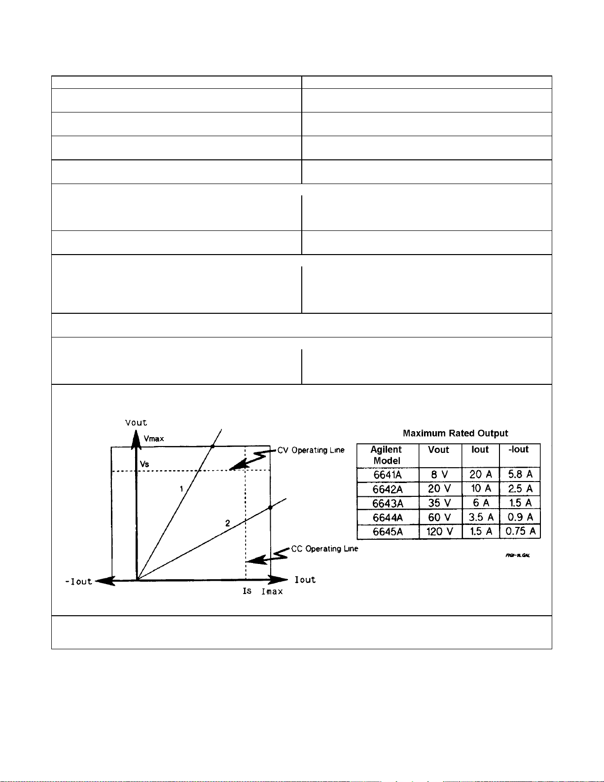
Table 1-1b. Supplemental Characteristics for Series 664xA (continued)
Parameter All Models
Digital Port Characteristics
GPIB Interface Capabilities
Serial Link Capabilities
Recommended Calibration Interval:
Safety Compliance
Complies with:
Designed to comply with:
RFI Suppression (complies with):
Dimensions
Width:
Height (including removable feet):
Depth (including safety cover):
Note 1: For Performance Specifications, see Table l-la.:
Weight
Net:
Shipping:
Output Characteristic Curve:
14.2 kg (31.4 lb)
16.3 kg (36 lb)
1
(see Table 1-5)
(see Table 1-5)
(see Table 1-5)
1 year
CSA 22.2 No.231,IEC 348
UL 1244
CISPR-ll, Group 1, Class B
425.5 mm (16.75 in)
88.1 mm (3.5 in)
439 mm (17.3 in)
Notes: lFor Performance Specifications, see Table l-la.
General Information 19
Page 20

Table 1-1b. Supplemental Characteristics for Series 664xA (continued)
Parameter All Models
Output Impedance Curves (Typical):
1
Notes: lFor Performance Specifications, see Table l-la.
General Information 20
Page 21

Table 1-2a. Performance Specifications for Series 665xA
1
Parameter Agilent Model Number
6651A 6652A 6653A 6654A 6655A
Output Ratings
Voltage:
Current:@ 40°°°°C
Current:@ 50°°°°C
Current:@ 55°°°°C
0 - 8 V 0 - 20 V 0- 35 V 0 - 60 V 0 - 120 V
0 - 50 A 0 - 25 A 0 - 15 A 0 - 9 A 0 - 4 A
0 - 45 A 0 - 22.5 A 0 - 13.5 A 0 - 8.1 A 0 - 3.6 A
0 - 42.5 A 0 - 21.3 A 0 - 12.8 A 0 - 7.7 A 0 -3.4 A
Programming Accuracy (@ 25 ± 5 °C)
Voltage: 2 0.06% +
Current: 0.l5 % +
5 mV
60 mA 25 mA
10 mV 15 mV
13 mA
26 mV 51 mV
8 mA
4 mA
Ripple & Noise (from 20 Hz to 20 MHz with outputs ungrounded, or with either output terminal grounded)
Constant Voltage: rms
Constant Voltage: p-p
Constant Current: rms
300 µV 300 µV 400 µV 500 µV 700 µV
3 mV 3 mV 4 mV 5 mV 7 mV
25 mA
10 mA 5 mA 3 mA 2 mA
Readback Accuracy (from front panel or over GPIB with respect to actual output @ 25 ± 5 °C)
Voltage: 2 0.07% +
+Current 0.15% +
-Current 0.35% +
6 mV 15 mV 25 mV 40 mV 80 mV
67 mA 26 mA 15 mA 7 mA 3 mA
100 mA 44 mA 24 mA 15 mA 7 mA
Load Regulation (change in output voltage or current for any load change within ratings)
Voltage:
Current:
1 mV 2 mV 3 mV 4 mV 5 mV
2 mA 1 mA 0.5 mA 0.5 mA 0.5 mA
Line Regulation (change in output voltage or current for any line change within ratings
Voltage:
Current:
0.5 mV 0.5 mV 1 mV 1 mV 2 mV
2 mA 1 mA 0.75 mA 0.5 mA 0.5 mA
Transient Response Time (for the output voltage to recover to its previous level (within 0.1% of the rated voltage or
20 mV, whichever is greater) following any step change in load current up to 50% of the rated current.
< 100 µs
AC Input Ratings (selectable via internal switching - see Appendix C)
Nominal line voltage:
Frequency:
Output Terminal Isolation
Notes:
2
3
1
For Supplemental Characteristics, see Table 1-2b.
Specification may degrade slightly when unit is subjected to an RF field ≥ 3V/meter.
For 230Vac operation, unit is internally set to 240Vac
100, 120, 220, 240 Vac (-13%, +6 %)
230 Vac
±240 Vdc (maximum, from chassis ground)
3
(-10%, +10%)
50/60 Hz
General Information 21
Page 22
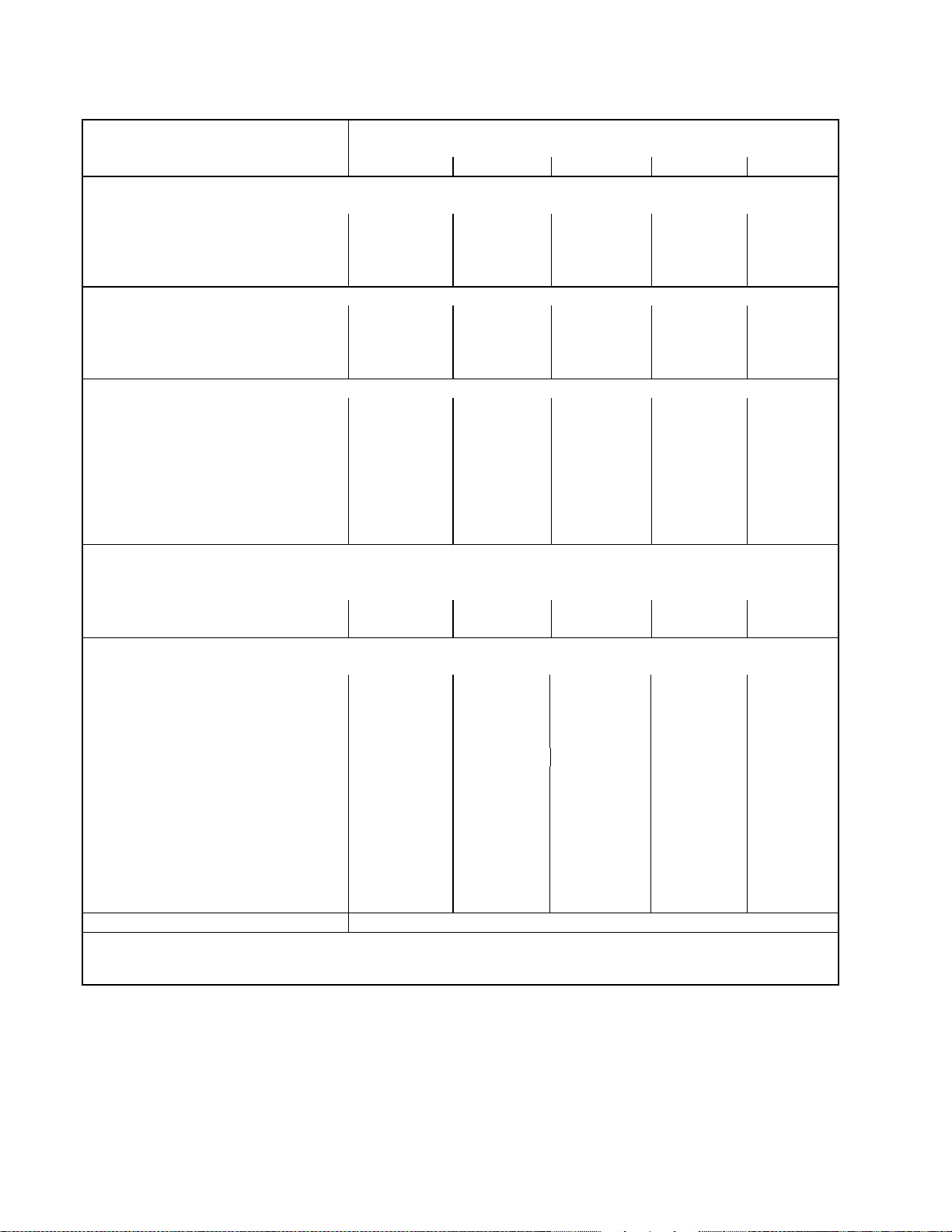
Table 1-2b. Supplemental Characteristics for Series 665xA
1
Parameter Agilent Model Number
6651A 6652A 6653A 6654A 6655A
Output Programming Range (maximum programmable values)
Voltage:
Current:
Overvoltage Protection (OVP):
8.190 V 20.475 V 35.831 V 61.425 V 122.85 V
51.188 A 25.594 A 15.356 A 9.214 A 4.095 A
8.8 V 22.0 V 38.5 V 66.0 V 132.0 V
Average Resolution
Voltage:
Current:
Overvoltage Protection (OVP):
2 mV 5 mV 10 mV 15 mV 30 mV
15 mA 7 mA 4 mA 2.5 mA 1 mA
13 mV 30 mV 54 mV 93 mV 190 mV
Accuracy
Overvoltage Protection (OVP):*
Analog Programming (VP):*
160 mV 400 mV 700 mV 1.2 V 2.4 V
0.36% + 6 mV 15 mV 27 mV 45 mV 90 mV
Analog Programming (IP):*
7% + 75 mA 31 mA 16 mA 8 mA 5 mA
Current Monitor (+IM):*
7% + 730 mA 400 mA 120 mA 80 mA 75 mA
*Referenced to supply output
Drift Temperature Stability (following a 30-minute warmup, change in output over eight hours under constant line,
load, and ambient temperature)
Voltage: 0.02% +
Current: 0.02% +
Temperature Coefficients (change per °C)
0.4 mV 1 mV 2 mV 3 mV 6 mV
40 mA 15 mA 8 mA 5 mA 2.5 mA
Voltage:
+Current:
Voltage Readback:
+Current Readback:
-Current Readback:
Overvoltage Protection (OVP):
Analog Programming (VP):
Analog Programming (IP):
Current Monitor (+IM):
Maximum Input Power
60 ppm + 0.1 mV 0.2 mV 0.3 mV 0.5 mV 1.1 mV
90 ppm + 1.4 mA 0.7 mA 0.3 mA 0.2 mA 0.2 mA
60 ppm + 0.2 mV 0.5 mV 0.75 mV 1.3 mV 2.6 mV
90 ppm + 1.7 mA 0.9 mA 0.5 mA 0.3 mA 0.2 mA
105 ppm + 1.7 mA 0.9 mA 0.5 mA 0.3 mA 0.2 mA
200 ppm + 1.6 mV 3.3 mV 5 mV 13 mV 24 mV
60 ppm + 0.1 mV 0.25 mV 0.4 mV 0.7 mV 1.25 mV
90 ppm + 1.4 mA 0.7 mA 0.3 mA 0.2 mA 0.15 mA
80 ppm + 1.4 mA 0.7 mA 0.3 mA 0.2 mA 0.15 mA
1380 VA; 1100 W, 120 W with no load
Notes: 1For Performance Specifications, see Table 1-2a.
General Information 22
Page 23
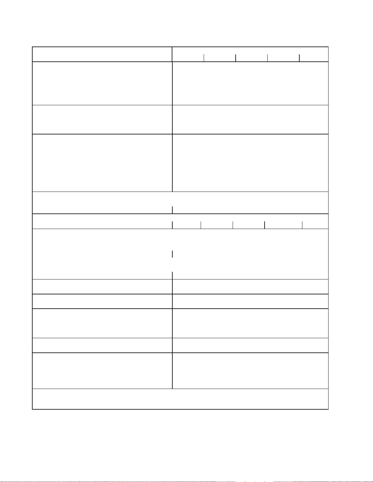
Table 1-2b. Supplemental Characteristics for Series 665xA (continued)
1
Parameter Agilent Model Number
6651A 6652A 6653A 6654A 6655A
Maximum AC Line Current Ratings
100 Vac nominal:
120 Vac nominal:
220 Vac nominal:
230 Vac nominal:
240 Vac nominal:
Maximum Reverse Bias Current:
12 A rms (15 AM fuse)
10 A rms (12 AM fuse)
5.7 A rms (7 AM fuse)
5.5 A rms (7 AM fuse)
5.3 A rms (7 AM fuse)
With AC input power applied and the dc output reverse
biased by an external dc source, the supply will continuously
withstand without damage a current equal to its output
current rating (see Table 1- 2a) .
Remote Sensing Capability
Voltage Drop Per Lead:
Load Regulation:
Load Voltage:
Up to 1/2 of rated output voltage.
Add 3 mV to spec (see Table l-2a) for each l-volt change in
the + output lead due to load current changes.
Subtract voltage drop in load leads from specified output
voltage rating.
Command Processing Time (Average time for output voltage to change after receipt of digital data when the supply
is connected directly to the GPIB Bus):
Downprogrammer Current Capability (± 15%):
11.6 A 5 A 3 A 1.8 A 1.5 A
20 ms
Output Voltage Programming Response Time
Rise/Fall Time (time for output to change from 90 % to 10% or from 10% to 90% of its total excursion):
<15 ms
Settling Time (time for output change to settle within 1 LSB (0.025% x rated voltage) of its final value):
Monotonicity:
Auto-Parallel Configuration:
Output is monotonic over entire rated voltage, current, and
temperature range.
Up to 3 identical models
<60 ms
Analog Programming (IP & VP)
Input Signal:*
Input Impedance:
*Signal source must be isolated.
Current Monitor Output (+IM):
Savable States
Nonvolatile Memory Locations:
Nonvolatile Memory Write Cycles:
Prestored State (factory default):
10 kΩ, nominal
0 to -5 V represents zero to full-scale current output.
5 ( 0 through 4)
0 to -5 V
40,000, typical
Location 0
Notes: lFor Performance Specifications, see Table l-2a.
General Information 23
Page 24

Table 1-2b. Supplemental Characteristics for Series 665xA (continued)
Parameter All Models
Digital Port Characteristics
GPIB Interface Capabilities
Serial Link Capabilities
Recommended Calibration Interval:
Safety Compliance
Complies with:
Designed to comply with:
RFI Suppression (complies with):
Dimensions
Width:
Height (including removable feet):
Depth (including safety cover):
Weight
Net:
Shipping:
Output Characteristic Curve:
25 kg (54 lb)
28 kg (61 lb)
1
(see Table 1-5)
(see Table 1-5)
(see Table 1-5)
1 year
CSA 22.2 No.231,IEC 348
UL 1244
CISPR-ll, Group 1, Class B
425.5 mm (16.75 in)
132.6 mm (5.22 in)
497.8 mm (19.6 in)
Notes: lFor Performance Specifications, see Table l-2a.
General Information 24
Page 25
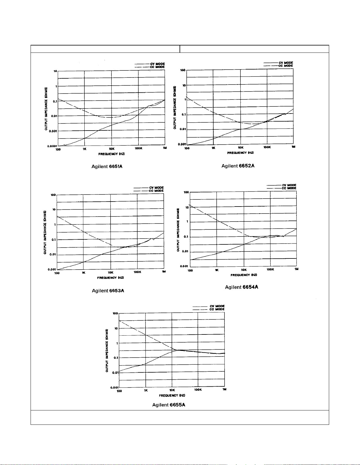
Table 1-2b. Supplemental Characteristics for Series 665xA (continued)
Parameter All Models
Output Impedance Curves (Typical):
1
Notes: lFor Performance Specifications, see Table l-2a.
General Information 25
Page 26

Table 1-3a. Performance Specifications for Series 667xA
1
Parameter Agilent Model Number
6671A 6672A 6673A 6674A 6675A
Output Ratings
Voltage:
Current:@ 0 to 55°°°°C
Programming Accuracy (@ calibration temperature* ± 5 °C)
0 - 8 V 0 - 20 V 0- 35 V 0 - 60 V 0 - 120 V
0 - 220 A 0 - 100 A 0 - 60 A 0 - 35 A 0 - 18 A
Voltage: 0.04% +
Current: 0 . l % +
8 mV
125 mA 60 mA
20 mV 35 mV
40 mA
60 mV 120 mV
25 mA
12 mA
Ripple & Noise (from 20 Hz to 20 MHz with outputs ungrounded, or with ei ther output terminal grounded)
Constant Voltage: rms
Constant Voltage: p-p
Constant Current: rms
650 µV 750 µV 800 µV
7 mV 9 mV 9 mV 11 mV 16 mV
200 mA
100 mA 40 mA 25 mA 12 mA
1.25 mV 1.9 mV
Readback Accuracy (from front panel or over GPIB with respect to actual output @ calibration temp1 ± 5 °C)
Voltage: 0.05% +
±±±±Current: 0.1% +
12 mV 30 mV 50 mV 90 mV 180 mV
150 mA 100 mA 60 mA 35 mA 18 mA
Load Regulation (change in output voltage or current for any load change within ratings)
Voltage: 0.002% +
Current: 0.005% +
300 µV 650 µV
10 mA 7 mA 4 mA 2 mA 1 mA
1.2 mV 2 mV 4 mV
Line Regulation (change in output voltage or current for any line change within ratings
Voltage: 0.002% +
Current: 0.005% +
300 µV 650 µV
10 mA 7 mA 4 mA 2 mA 1 mA
1.2 mV 2 mV 4 mV
bisep>
Transient Response Time (for the output voltage to recover to its previous level (within 0.1% of the rated voltage or
20 mV, whichever is greater) following any step change in load current up to 50% of the rated current.
< 900 µs
AC Input Ratings (selectable via internal switching - see Appendix C)
Nominal line voltage:
220, 230, 240 Vac (191-253 Vac range)
200 Vac (174-220 Vac range)*
*below 185 Vac, derate output voltage linearly to:
7.8 V 18.0 V 31.5 V 56.5 V 108 V
Frequency:
Output Terminal Isolation
±240 Vdc (maximum, from chassis ground)
50/60 Hz
Notes: 1For Supplemental Characteristics, see Table 1-3b.
General Information 26
Page 27

Table 1-3b. Supplemental Characteristics for Series 667xA
1
Parameter Agilent Model Number
6671A 6672A 6673A 6674A 6675A
Output Programming Range (maximum programmable values)
Voltage:
Current:
Overvoltage Protection (OVP):
8.190 V 20.475 V 35.831 V 61.425 V 122.85 V
225.23 A 102.37 A 61.43 A 35.83 A 18.43 A
10.0 V 24.0 V 42.0 V 72.0 V 144.0 V
Typical Resolution
Voltage:
Current:
Overvoltage Protection (OVP):
2 mV 5 mV 10 mV 15 mV 30 mV
55 mA 25 mA 15 mA 8.75 mA 4.5 mA
15 mV 35 mV 65 mV 100 mV 215 mV
Accuracy ( @ calibration temp ±5 °C)*
Overvoltage Protection (OVP):*
Analog Programming (VP):
Analog Programming (IP):
Current Monitor (+IM):
*Calibration temp = 25° C
200 mV 500 mV 900 mV 1.15 V 3.0 V
± 0.3%
± 7%
±7%
Drift Temperature Stability (following a 30-minute warmup, change in output over eight hours under constant line,
load, and ambient temperature)
Voltage: 0.02% +
Current: 0.02% +
Temperature Coefficients (change per °C after 30-minute warmup)
0.24 mV 0.6 mV 1 mV 1.8 mV 3.6 mV
69 mA 35 mA 20 mA 10 mA 6 mA
Voltage:
Current:
Voltage Readback:
±±±±Current Readback:
Overvoltage Protection (OVP):
Analog Programming (VP):
Analog Programming (±±±±IP):
Current Monitor (+IM):
Maximum Input VA and Power
Maximum AC Line Current Ratings
50 ppm + 0.04 mV 0.2 mV 0.7 mV 1.2 mV 2.4 mV
75 ppm + 25 mA 12 mA 7 mA 4 mA 2 mA
60 ppm + 0.1 mV 0.3 mV 1 mV 1.2 mV 3 mV
85 ppm + 30 mA 15 mA 9 mA 5 mA 2.5 mA
200 ppm + 1.8 mV 5 mV 8 mV 13 mV 25 mV
60 ppm + 0.1 mV 0.3 mV 0.5 mV 0.7 mV 1.5 mV
275 ppm + 26 mA 14 mA 9 mA 5 mA 3 mA
50 ppm + 3 mA 2 mA 1 mA 0.6 mA 0.3 mA
3800 VA; 2600 W, 100 W with no load
200 Vac
nominal:
230 Vac
19 A rms (25 AM fuse)
19 A rms (25 AM fuse)
nominal:
Maximum Reverse Bias Current:
With AC input power applied and the dc output reverse biased by an
external dc source, the supply will continuously withstand without damage a
current equal to its output current rating (see Table 1-3a).
Notes: 1For Performance Specifications, see Table 1-3a.
General Information 27
Page 28
Table 1-3b. Supplemental Characteristics for Series 667xA (continued)
1
Parameter Agilent Model Number
6671A 6672A 6673A 6674A 6675A
Remote Sensing Capability
Voltage Drop Per Lead:
Load Voltage:
Up to 1/2 of rated output voltage.
Subtract voltage drop in load leads from specified output
voltage rating.
Load Regulation:
Degradation due to load lead drop in--output: ∆mV (regulation) = Vdrop(R
sense-
)/k
Degradation due to load lead drop in + output:
∆mV (regulation) = V
where R
sense
- and R
drop(Rsense
sense
+)/k + 2V
drop(Vrating
+ are resistances of respective sense leads and k is the following model-dependent
)/(V
+ 10 V)
rating
value:
6671A=1; 6672A=1.82; 6673A=4.99; 6674A=10; 6675A=16.2
Command Processing Time (Average time for output voltage to change after receipt of digital data when the supply
is connected directly to the GPIB Bus):
20 ms
Output Voltage Programming Response Time**
Rise/Fall Time (time for output to change from 90 % to 10% or from 10% to 90% of its total excursion):***
30 ms 60 ms 130 ms 130 ms 195 ms
Full-load programming speed up/down time (time for output to settle within 4 LSBs of the final value):***
85 ms 190 ms 380 ms 380 ms 600 ms
No-load downprogrammiug discharge time (time for output to fall to 0.5 V when programmed from full voltage to
zero volts):
130 ms 250 ms 350 ms 600 ms 600 ms
** All values exclude command processing time.
*** With full resistive load = V
Monotonicity:
Auto-Parallel Configuration:
RATED/IRATED.
Output is monotonic over entire rated voltage, current, and
temperature range.
Up to 3 identical models
Analog Programming (IP & VP)
Input Signal:*
VP Input Signal:** (0 to )
VP Input Impedance:
IP to -IP Differential Input Signal: (0 to )
*Signal source must be isolated.
-4.72 V -4.24 V -4.25 V -4.24 V -3.97 V
60 kΩ, nominal
+7.79 V +6.81 V +6.81 V =7.01 V +6.34 V
** Referenced to output signal common.
Current Monitor Output (+IM):
Output Signal:* (-0.25 to )
Output Impedance:
+9.05 V +7.70 V +7.70 V +7.93 v +7.15 V
490 Ω
* Corresponds to 0% to 100% output current.
Savable States
Nonvolatile Memory Locations:
Nonvolatile Memory Write Cycles:
Prestored State (factory default):
5 ( 0 through 4)
40,000, typical
Location 0
Notes: lFor Performance Specifications, see Table l-3a.
General Information 28
Page 29

Table 1-3b. Supplemental Characteristics for Series 667xA (continued)
Parameter All Models
Digital Port Characteristics
GPIB Interface Capabilities
Serial Link Capabilities
Recommended Calibration Interval:
Safety Compliance
Complies with:
Designed to comply with:
RFI Suppression (complies with):
Dimensions
Width:
Height (including removable feet):
Depth (including safety cover):
Weight
Net:
Shipping:
Output Characteristic Curve:
1
(see Table 1-5)
(see Table 1-5)
(see Table 1-5)
1 year
CSA 22.2 No.231,IEC 348
UL 1244
CISPR-ll, Group 1, Class B
425.5 mm (16.75 in)
145.1 mm (5.71 in)
640 mm (25.2 in)
27.7 kg (61 lb)
31.4 kg (69 lb)
Notes: lFor Performance Specifications, see Table l-3a.
General Information 29
Page 30
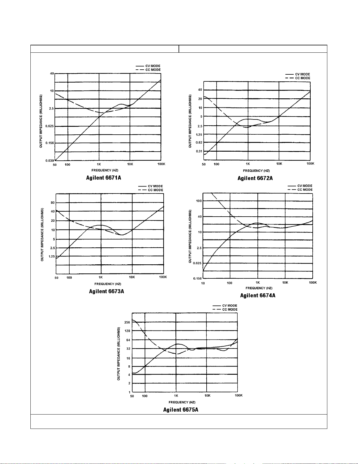
Table 1-3b. Supplemental Characteristics for Series 667xA (continued)
Parameter All Models
Output Impedance Curves (Typical):
1
Notes: lFor Performance Specifications, see Table l-3a.
General Information 30
Page 31

Table 1-4a. Performance Specifications for Series 668xA
1
Parameter Agilent Model Number
6680A 6681A 6682A 6683A 6684A
Output Ratings
Voltage:
Current:*
*Derated linearly 1%/°C from 40 ° C to 55 °C
0 - 5 V 0 - 8 V 0- 21 V 0 - 32 V 0 - 40 V
0 - 875 A 0 - 580 A 0 - 240 A 0 - 160 A 0 - 128 A
Programming Accuracy (@ 25 ± 5 °C)
Voltage: 0.04% +
Current: 0 . l % +
5 mV 8 mV 21 mV 32 mV 40 mV
450 mA 300 mA
125 mA
85 mA
65 mA
Ripple & Noise (from 20 Hz to 20 MHz with outputs ungrounded, or with ei ther output terminal grounded)
Constant Voltage: rms
Constant Voltage: p-p
1.5 mV 1.5 mV 1.5 mV 1.0 mV 1.0 mV
10 mV 10 mV 10 mV 10 mV 10 mV
Readback Accuracy (from front panel or over GPIB with respect to actual output @ 25 ± 5 °C)
Voltage: 0.05% +
±±±±Current 0.1% +
7.5 mV 12 mV 32 mV 48 mV 60 mV
600 mA 400 mA 165 mA 110 mA 90 mA
Load Regulation (change in output voltage or current for any load change within ratings)
Voltage 0.002% +
Current: 0.005% +
190 µV 300 µV 650 µV
65 mA 40 mA 17 mA 12 mA 9 mA
1.1 mV 1.5 mV
Line Regulation (change in output voltage or current for any line change within ratings)
Voltage: 0.002% +
Current: 0.005% +
190 µV 300 µV 650 µV
65 mA 40 mA 17 mA 12 mA 9 mA
1.1 mV 1.5 mV
Transient Response Time (for the output voltage to recover to within 150 mV following any step change from 100% to
50% or 50% to 100% of the rated output current): < 900 µs
AC Line Input * (selectable - see Appendix C)
Range 1 (180-235 Vac)
Nominal phase-to-phase voltage:
Input frequency:
Range 2 (360-440 Vac)
Nominal phase-to-phase voltage:
Input frequency:
200, 208 Vac (3-phase)
400, 416 Vac (3-phase)
50/60 Hz *
50/60 Hz
* Power source can be DELTA or WYE.
* For 50 Hz on Range 1 only, derate output voltage linearly from 100% at 200 Vac to 95% at 180 Vac.
Notes: 1For Supplemental Characteristics, see Table 1-4b.
General Information 31
Page 32

Table 1-4b. Supplemental Characteristics for Series 668xA
1
Parameter Agilent Model Number
6680A 6681A 6682A 6683A 6684A
Ripple & Noise (from 20 Hz to 20 MHz with outputs ungrounded, or with either output terminal grounded)
Constant Current:** rms
**With load inductance > 5µH.
290 mA
190 mA 40 mA 28 mA 23 mA
Output Programming Range (maximum programmable values)
Voltage:
Current:
Overvoltage Protection (OVP):
5.125 V 8.190 V 21.50 V 32.8 V 41.0 V
895 A 592 A 246 A 164 A 131 A
6.25 V 10.0 V 26.3 V 40.0 V 50.0 V
Typical Resolution
Voltage:
Current:
Overvoltage Protection (OVP):
1.35 mV 2.15 mV 5.7 mV 8.6 mV 10.8 mV
235 mA 155 mA 64 mA 43 mA 34 mA
30 mV 45 mV 120 mV 180 mV 225 mV
Accuracy ( @ 25 ±5 °C)*
Overvoltage Protection (OVP):
Analog Programming (VP): ±0.3%±
Analog Programming (IP):±2% ±
Current Monitor (IM):±2%±
120 mV 180 mV 470 mV 720 V 900 V
10 mV 20 mV 50 mV 75 mV 100 mV
8 A 4 A 2 A 1.5 A 1 A
8 A 4 A 2 A 1.5 A 1 A
Analog Programming (VP & IP)
Input Signal (source must be isolated)
VP Input Signal:*
+ IP Input Signal:**
Input Impedance
VP and IP Inputs:
*Referenced to common ↓P.
** Referenced to -IP differential input signal
0 to -5.0 V
0 to +5.0 V
> 30 kΩ
Current Monitor (IM) Output Signal: -0.125 V to +5 V
Drift Temperature Stability (following a 30-minute warmup, change in output over eight hours under constant line,
load, and ambient temperature)
Voltage: 0.02% +
Current: 0.02% +
0.15 mV 0.24 mV 0.63 mV 0.96 mV 1.2 mV
315 mA 170 mA 71 mA 47 mA 38 mA
Temperature Coefficients (change per °C after 30-minute warmup)
Voltage:
Current:
Voltage Readback:
±±±±Current Readback:
Overvoltage Protection (OVP):
50 ppm + 0.05 mV 0.08 mV 0.21 mV 0.32 mV 0.40 mV
75 ppm + 110 mA 62 mA 26 mA 17 mA 14 mA
60 ppm + 0.075 mV 0.1 mV 0.25 mV 0.40 mV 0.50 mV
85 ppm + 135 mA 90 mA 37 mA 25 mA 20 mA
200 ppm + 1.25 mV 1.8 mV 4.7 mV 7.2 mV 9.0 mV
Typical Common Mode Noise Current*
rms:
peak-to-peak:
1.5 mA
10 mA
1.5 mA
10 mA
3 mA
20 mA
3 mA
20 mA
3 mA
20 mA
* Referenced to signal ground binding post.
Output Float Voltage (maximum from output signal ground): ±60 Vdc
Notes: 1For Performance Specifications, see Table 1-4a.
General Information 32
Page 33

Table 1-4b. Supplemental Characteristics for Series 668xA (continued)
1
Parameter Agilent Model Number
6680A 6681A 6682A 6683A 6684A
Remote Sensing Capability
Voltage Drop Per Lead:
Load Voltage:
Up to 1/2 of rated output voltage.
Subtract voltage drop in load leads from specified output
voltage rating.
Load Regulation:
Degradation due to load lead drop in--output: ∆mV (regulation) = Vdrop(R
sense
-)
Degradation due to load lead drop in + output:
∆mV (regulation) = V
where R
sense
_ and R
drop(Rsense
sense +
+) + 2V
drop(Vrating
are resistances of respective sense leads.
)/(V
+ 10 V)
rating
Maximum Reverse Voltage Current Sink Capability: *
With ac input power applied and the dc output reverse biased
by an external dc source, the supply will continuously
withstand without damage a current equal to its output
current rating.
* Current must be limited by user's external dc source.
Load Voltage:
Subtract voltage drop in load leads from specified output
voltage rating.
Maximum Input Power:
7350 VA,
6000 W,
160 W (with no load)
Maximum AC Line Current Ratings
Range 1
Rms line current:
Line fuse:
21.4 A (27.7 A) ***
30 AM
Range 2
Rms line current:
Line fuse:
10.7 A (14.4 A) ***
16 AM
*** Includes 5% unbalanced voltage phase condition.
Output Voltage Programming Response Time**
Programming Rise/Fall Time (time for output to change from 90 % to 10% or from 10% to 90% of its total
excursion):***
9 ms 12 ms 45 ms 60 ms 60 ms
Full-load programming speed up/down time (time for output to settle within 4 LSBs of the final value):***
27 ms 35 ms 140 ms 185 ms 185 ms
No-load downprogrammiug discharge time (time for output to fall to 0.5 V when programmed from full voltage to
zero volts):
90 ms 100 ms 475 ms 650 ms 575 ms
** All values exclude command processing time.
*** With full resistive load = V
RATED/IRATED
Notes: lFor Performance Specifications, see Table l-4a.
General Information 33
Page 34

Table 1-4b. Supplemental Characteristics for Series 668xA (continued)
1
Parameter All Models
Command Processing Time (Average time for output voltage to change after receipt of digital data when the supply is
connected directly to the GPIB Bus): 20 ms
Monotonicity:
Auto-Parallel Configuration:
Output is monotonic over entire rated voltage, current, and
temperature range.
Up to 3 identical models
Nonvolatile Storage
State storage & recall locations:
Prestored turn-on state:
Maximum memory write cycles:
Digital Port Characteristics
GPIB Interface Capabilities
Serial Link Capabilities
Recommended Calibration Interval:
Safety Compliance
Complies with:
Designed to comply with:
RFI Suppression (complies with):
Dimensions
Width:
Height
including removable feet
excluding removable feet
Depth (without output safety cover):
Weight
Net:
Shipping:
(see Table 1-5)
(see Table 1-5)
(see Table 1-5)
CSA 22.2 No.231,
IEC 1010 (carries CE mark)
CISPR-ll, Group 1, Class B
425.5 mm (16.75 in)
234.2 mm (9.25 in)
221.5 mm (8.75 in)
674.7 mm (25.56 in)
51.3 kg (113 lb)
63.6 kg (140 lb)
4
Location 0
40,000, typical
1 year
UL 1244
Output Characteristic Curve:
Notes: lFor Performance Specifications, see Table l-4a.
General Information 34
Page 35

Table 1-4b. Supplemental Characteristics for Series 668xA (continued)
Parameter All Models
Output Impedance Curves (Typical):
20
*
10
5
**
2.5
1.25
0.625
0.312
0.156
OUTPUT IMPEDANCE (MILLIO HMS)
0.078
0.039
0.0195
30
100
1K
FREQUENCY (HZ)
Agilent 6680A
*
40
40
**
20
10
5
2.5
1.25
0.625
0.312
OUTPUT IMPEDANCE (MILLIOHMS)
0.156
0.0781
0.0391
30
100 1K 10K
FREQUENCY (HZ)
Agilent 6682A
* ALL COMPENSATION SWITCHES OPEN
** ALL COMPENSATION SWITCHES CLOSED
Notes:
CV MODE
CC MODE
10K
50K
CV MODE
CC MODE
50K
OUTPUT IMPEDANCE (MILLIOHMS)
OUTPUT IMPEDA NCE (MILLIOHMS)
**
1.25
0.625
0.312
0.156
0.078
0.039
0.195
1.25
0.625
0.312
0.156
0.0781
*
20
10
5
2.5
30
100
FREQUENCY (HZ)
Agilent 6681A
*
80
**
40
20
10
5
2.5
30
100 1K 10K
** *
80
40
20
10
5
2.5
1.25
O.625
OUTPUT IMPEDANCE (MILLIOHMS)
O.312
0.156
0.0781
30
l
For Performance Specifications, see Table l-4a.
100 1K
1K
FREQUENCY (H Z)
Agilent 6683A
FREQUENCY ( HZ )
Agilent 6684A
1
CV MODE
CC MODE
10K
50K
CV MODE
CC MODE
50K
CV MODE
CC MODE
10K
50K
General Information 35
Page 36

Table 1-5a. Performance Specifications for Series 669xA
1
Parameter Agilent Model Number
6690A 6691A 6692A
Output Ratings
Voltage:
Current:*
*Derated linearly 1%/°C from 40 ° C to 55 °C
0 - 15 V 0 - 30 V 0- 60 V
0 - 440 A 0 - 220 A 0 – 110 A
Programming Accuracy (@ 25 ± 5 °C)
Voltage: 0.04% +
Current: 0. l % +
15 mV 30 mV 60 mV
230 mA 125 mA
65 mA
Ripple & Noise (from 20 Hz to 20 MHz with outputs ungrounded, or with ei ther output terminal grounded)
Constant Voltage: rms
Constant Voltage: p-p
2.5 mV 2.5 mV 2.5 mV
15 mV 25 mV 25 mV
Readback Accuracy (from front panel or over GPIB with respect to actual output @ 25 ± 5 °C)
Voltage: 0.05% +
±±±±Current 0.1% +
22.5 mV 45 mV 90 mV
300 mA 165 mA 80 mA
Load Regulation (change in output voltage or current for any load change within ratings)
Voltage 0.002% +
Current: 0.005% +
650 µV
40 mA 17 mA 9 mA
1.1 mV 2.2 mV
Line Regulation (change in output voltage or current for any line change within ratings)
Voltage: 0.002% +
Current: 0.005% +
650 µV 650 µV 650 µV
40.5 mA 17 mA 9 mA
Transient Response Time (for the output voltage to recover to within 150 mV following any step change from 100% to
50% or 50% to 100% of the rated output current): < 900 µs
AC Line Input * (selectable - see Appendix C)
Range 1 (180-235 Vac)
Nominal phase-to-phase voltage:
Input frequency:
Range 2 (360-440 Vac)
Nominal phase-to-phase voltage:
Input frequency:
200, 208 Vac (3-phase)
400, 416 Vac (3-phase)
50/60 Hz
50/60 Hz
* Power source can be DELTA or WYE.
Notes: 1For Supplemental Characteristics, see Table 1-5b.
General Information 36
Page 37

Table 1-5b. Supplemental Characteristics for Series 669xA
1
Parameter Agilent Model Number
6690A 6691A 6692A
Ripple & Noise (from 20 Hz to 20 MHz with outputs ungrounded, or with either output terminal grounded)
Constant Current:** rms
**With load inductance > 5µH.
200 mA
50 mA 30 mA
Output Programming Range (maximum programmable values)
-Max Power 6.67KW
Voltage:
Current:
Overvoltage Protection (OVP):
15.375 V 30.75 V 61.5 V
450 A 225 A 112 A
18 V 36 V 69 V
Typical Resolution
Voltage:
Current:
Overvoltage Protection (OVP):
4.1 mV 8.1 mV 16 mV
118.5 mA 59 mA 30 mA
90 mV 170 mV 330 mV
Accuracy ( @ 25 ±5 °C)*
Overvoltage Protection (OVP):
Analog Programming (VP): 0.3% +
Analog Programming (IP): 2% +
Current Monitor (IM): 2% +
350 mV 675 mV 1.3 V
40 mV 75 mV 150 mV
3 A 2 A 1 A
3 A 2 A 1 A
Analog Programming (VP & IP)
Input Signal (source must be isolated)
VP Input Signal:*
+ IP Input Signal:**
Input Impedance
VP and IP Inputs:
*Referenced to common ↓P.
Current Monitor (IM) Output Signal:
** Referenced to -IP differential input signal
0 to -5.0 V
0 to +5.0 V
> 30 kΩ
-0.125 V to +5 V
Drift Temperature Stability
(following a 30-minute warmup, change in output over eight hours under constant line, load, and ambient temperature)
Voltage: 0.02% +
Current: 0.02% +
0.45 mV 0.90 mV 1.8 mV
130 mA 65 mA 33 mA
Temperature Coefficients (change per °C after 30-minute warmup)
Voltage:
Current:
Voltage Readback:
±±±±Current Readback:
Overvoltage Protection (OVP):
50 ppm + 0.30 mV 0.30 mV 0.60 mV
75 ppm + 48 mA 24 mA 12 mA
60 ppm + 0.20 mV 0.4 mV 0.75 mV
85 ppm + 70.5 mA 40 mA 17 mA
200 ppm + 3.6 mV 6.5 mV 13 mV
Typical Common Mode Noise Current*
rms:
peak-to-peak:
3 mA
20 mA
3.5 mA
20 mA
4 mA
25 mA
* From 20Hz to 2MHz; Referenced to signal ground binding post.
Output Float Voltage (maximum from output signal ground): ±60 Vdc
Notes: 1For Performance Specifications, see Table 1-5a.
General Information 37
Page 38

Table 1-5b. Supplemental Characteristics for Series 669xA (continued)
1
Parameter Agilent Model Number
6690A 6691A 6692A
Remote Sensing Capability
Voltage Drop Per Lead:
Load Voltage:
Up to 1/2 of rated output voltage.
Subtract voltage drop in load leads from specified output
voltage rating.
Load Regulation:
Degradation due to load lead drop in--output: ∆mV (regulation) = Vdrop(R
sense
-)
Degradation due to load lead drop in + output:
∆mV (regulation) = V
where R
sense
_ and R
drop(Rsense
sense +
+) + 2V
drop(Vrating
are resistances of respective sense leads.
)/(V
+ 10 V)
rating
Maximum Reverse Voltage Current Sink Capability: *
With ac input power applied and the dc output reverse biased
by an external dc source, the supply will continuously
withstand without damage a current equal to its output
current rating.
* Current must be limited by user's external dc source.
Maximum Input Power:
9000 VA,
7950 W,
175 W (with no load)
Maximum AC Line Current Ratings
Range 1
Rms line current:
Line fuse:
26 A ***
40 AM
Range 2
Rms line current:
Line fuse:
13 A***
20 AM
Output Voltage Programming Response Time**
Programming Rise/Fall Time (time for output to change from 90 % to 10% or from 10% to 90% of its total
excursion):***
45 ms 60 ms 100 ms
Full-load programming speed up/down time (time for output to settle within 4 LSBs of the final value):***
150 ms 185 ms 280 ms
No-load downprogrammiug discharge time (time for output to fall to 0.5 V when programmed from full voltage
to zero volts):
340 ms 650 ms 870 ms
** All values exclude command processing time.
*** With full resistive load = V
RATED/IRATED
Notes: lFor Performance Specifications, see Table l-5a.
General Information 38
Page 39

Table 1-5b. Supplemental Characteristics for Series 669xA (continued)
1
Parameter All Models
Command Processing Time (Average time for output voltage to change after receipt of digital data when the supply is
connected directly to the GPIB Bus): 20 ms
Monotonicity:
Auto-Parallel Configuration:
Output is monotonic over entire rated voltage, current, and
temperature range.
Up to 3 identical models
Nonvolatile Storage
State storage & recall locations:
Prestored turn-on state:
Maximum memory write cycles:
Digital Port Characteristics
GPIB Interface Capabilities
Serial Link Capabilities
Recommended Calibration Interval:
Safety Compliance
Complies with:
Designed to comply with:
RFI Suppression (complies with):
Dimensions
Width:
Height
including removable feet
excluding removable feet
Depth (without output safety cover):
Weight
Net:
Shipping:
(see Table 1-6)
(see Table 1-6)
(see Table 1-6)
CSA 22.2 No.231,
IEC 1010 (carries CE mark)
CISPR-ll, Group 1, Class B
425.5 mm (16.75 in)
234.2 mm (9.25 in)
221.5 mm (8.75 in)
674.7 mm (25.56 in)
51.3 kg (113 lb)
63.6 kg (140 lb)
4
Location 0
40,000, typical
1 year
UL 1244
Output Characteristic Curve:
Output Characteristic Curve:
Vout
Vmax
Vset
1
CV operating
line
2
Maximun Rated Output
Agilent
Model
Vout
Iout
6690A
15V
440A
CC operating line
0
Iset
Imax
Iout
6691A
6692A
30V
60V
220A
110A
Notes: lFor Performance Specifications, see Table l-4a.
General Information 39
Page 40

Table 1-5b. Supplemental Characteristics for Series 669xA (continued)
Parameter All Models
Output Impedance Curves (Typical):
Agilent 6690A
Agilent 6691A
1
CC mode
1000
*
100
**
10
1
Magnitude (in milliohms)
0.1
0.01
10 100 1000 10000 100000
1000
Frequency (in Hz)
CV mode
CC mode
CV mode
*
100
**
10
Agilent 6692A
* All compensation switches open
** All compensation switches closed
1
Magnitude (in milliohms)
0.1
0.01
10 100 1000 10000 100000
*
1000
**
100
10
1
Magnitude (in milliohms)
0.1
10 100 1000 10000 100000
Frequency (in Hz)
Frequency (in Hz)
Notes: lFor Performance Specifications, see Table l-4a.
CC mode
CV mode
General Information40
Page 41

Table 1-6. Supplemental GPIB Characteristics for All Models
Parameter
Digital Port Characteristics
Maximum ratings:
FLT/INH Operation
16.5Vdc between terminals 1&2; 3&4; and from 1 or 2 to chassis ground
FLT/INH Terminals 1 & 2:
Iol (low-level output current)
V
(low-level output voltage)
ol
1.25 mA maximum
FLT/INH Terminals 3 & 4:
Vil (low-level input voltage)
V
(high-level input voltage)
ih
I
(low-level input current)
il
tw (pulse width)
td (time delay)
Digital I/O Operation
Digital OUT Port 0,1,2 - Open Collector:
Ioh (high-level output leakage @ 16.5 V)
I
(high-level output leakage @ 5.25 V)
oh
I
(low-level output sink current @ 0.5 V)
ol
I
(low-level output sink current @ l V)
ol
100 µA (ports 0,1); 12.5 mA (port 2)
100 µA (ports 0,1); 250 µA (port 2)
Digital IN Port 2 - Internal 4.64 k Pullup:
Iil (low-level input current @ 0.4 V)
I
(high-level input current @ 5.25 V)
ih
V
(low-level input voltage)
il
V
(high-level input voltage)
ih
GPIB Interface Capabilities
Languages:
Interface:
AH1, C0, DC1, DT1, E1, LE4, PP0, RL1, SH1, SR1, TE6
SCPI (default); Compatibility
Serial Link Capabilities (multiple supplies sharing one GPIB primary address)
Maximum number of supplies:
Maximum number of linked supplies:
Maximum total chain cable length:
Table 1-7. Operator Replaceable Parts List
Description
(Unless otherwise specified, parts apply to all models.)
Cable assembly, GPIB
Cable assembly, serial link
Collar, rotary output control
Cover, ac input safety
Series 667xA, w/strain relief connector & rubber boot
Series 668xA, w/strain relief connector & rubber boot
Series 669xA, w/strain relief connector & rubber boot
Cover, dc output
Series 664xA and 665xA
Series 667xA
Series 668xA
Series 669xA
Flatwasher, ac input safety cover (Series 667xA, 668xA)
Foot, cabinet
All Models
0.5 V maximum
0.8 V maximum
2.0 V minimum
1 mA
100 µs, minimum
4 ms, typical
4 mA
250 mA
1.25 mA
250 µA
0.8 V maximum
2.0 V minimum
16
15
30 m (100 ft)
-
Agilent Part No.
(See “Accessories”)
(See “Accessories”)
5040-l700
5040-1676
5060-3237
5002-1592
0360-2191
5040-1674
5040-1692
5040-1692
3050-1053
5041-8801
General Information 41
Page 42

Table 1-7. Operator Replaceable Parts List (continued)
Description
(Unless otherwise specified, parts apply to all models.)
Fuses, Series 664xA
M6A 250V (for 100 Vac line voltage, reference designator F450)
M5A 250V (for 120 Vac line voltage, reference designator F450)
M3A 250V (for 220/230/240 Vac line voltage, reference designator F450)
M15A 32V (for secondary rail bias, reference designator F402, F403)
M5A 125V (for ac bias, reference designator F600, F601)
M.125A 125V (for control circuits, reference designator F675, F700, 701)
Fuseholder for Line (Littelfuse 345 101; UL, CSA, SEMKO, VDE approved; 6.3/15A, 250V)
Line Fuses, Series 665xA
100 Vac line voltage, 15 AM
120 Vac line voltage, 12 AM
220/230/240 Vac line voltage, 7 AM
Line Fuses, Series 667xA *
*This is an internal fuse not replaceable by the operator.
Line Fuses, Series 668xA
16 AM for 360-440 Vac line (set of 3)
30 AM for 180-235 Vac line (set of 3)
Line Fuses, Series 669xA
20 AM for 360-440 Vac line (set of 3)
40 AM for 180-235 Vac line (set of 3)
Knob, rotary output control
Lockwasher, ac input safety cover (Series 667xA and 668xA)
Lockwasher, output bus bar, 1/4 spring (Series 667xA only)
Manual
Agilent 59510A/11 Relay Accessories
Series 603xA Operating
Series 664xA and 665xA Service
Series 664xA, 665xA, 667xA, 668xA, and 669xA Programming Guide
Series 667xA Service
Nut, output bus bar, hex 1/4-20x1/2 (Series 667xA)
Nut, power ground, hex w/lw 3/8x32 (Series 667xA)
Nut, power input cable (Series 668xA)
Nut, power input cable (Series 669xA)
Plug, analog connector
Plug, digital connector
Power cord assembly
Rack mount kit
Resistor, calibration
Screw, ac input safety cover, M4.0 x 60 mm long (Series 667xA, 668xA)
Screw, ac input safety cover, M4.0 x 60 mm long (Series 669xA)
Screw, carrying strap, M5x0.8x10 mm
Screw, dc output cover (Series 664xA and 665xA)
Screw, output bus bar
Series 665xA
Series 667xA, 1/4-20x1/2
Screw, outer cover, M5 x 0.8 mm
Screw, output sense terminal, M3x0.5x8mm (Series 667xA, 668xA, 669xA)
Slide mount kit
Standoff, GPIB
Terminal, crimp, ac power cord (Series 667xA only)
L or N terminal
Gnd terminal
Agilent Part No.
2110-0056
2110-0010
2110-0003
2110-0697
2110-0699
2110-0671
2110-0927
2110-0054
2110-0249
21l0-06l4
5060-3512
5060-3513
5065-6935
5065-6934
0370-1091
2190-0484
3050-1690
5957-6382
5959-3301
5959-3376
5964-8269
5959-3384
2950-0084
0590-0305
0535-0082
0535-0038
1252-3698
1252-1488
(See "Options" )
(See "Options")
(See Appendix A)
0515-0156
0515-0380
0515-1384
0360-219l
0515-1085
2940-0103
0515-0073
0515-0104
( “See Accessories” )
0380-0643
0362-0681
0362-0207
General Information 42
Page 43

2
Installation
Inspection
Damage
When you receive your power supply, inspect it for any obvious damage that may have occurred during shipment. If there is
damage, notify the shipping carrier and the nearest Agilent Sales and Support Office immediately. Warranty information is
printed in the front of this guide.
Packaging Material
Until you have checked out the power supply save the shipping carton and packing materials in case the power supply has to
be returned to Agilent Technologies. If you return the power supply for service, attach a tag identifying the model number
and the owner. Also include a brief description of the problem.
Items Supplied
In addition to this manual, check that the following items in Table 2-1 are included with your power supply (see Table 1-6
for part numbers):
Table 2-1. Items Supplied
Power cord Series 664xA and 665xA
Your power supply was shipped with a power cord for the type of outlet specified for your location. If
the appropriate cord was not included, contact your nearest Agilent Sales and Support Offices (see end
of this guide) to obtain the correct cord. Caution: Your power supply cannot use a standard power cord.
The power cords supplied by Agilent Technologies have heavier gauge wire.
Series 667xA, 668xA, 669xA
Your power supply was shipped with a power cord appropriate for your location. The cord may or may
not be terminated in a power plug (see "Options" in Chapter 1). If the cord is not included, contact your
nearest Agilent Sales and Support Office (see end of this guide ) to obtain the correct cord. These
models also include a power input safety cover with strain relief connector. It is required to secure the
power cord to the power supply.
Analog
connector
Digital
connector
Serial cable
A 7-terminal analog plug (see Table 1-6) that connects to the back of the supply. Analog connections are
described in Chapter 4.
A 4-terminal digital plug (see Table 1-6) that connects to the back of the supply. Digital connections are
described in "Appendix D - Digital Port Functions"
A 2-meter cable (see “Accessories” in Chapter 1) that connects to the control bus (next to the GPIB
connector). This cable is used to serially connect multiple supplies as described under "Controller
Connections" in Chapter 4.
Installation 43
Page 44

Table 2-1. Items Supplied (continued)
Output
hardware
Guide change
page
Series 667xA only
Output hardware (screws with nuts and lockwashers) for securing your load wires to the output bus bars
(see Table 1-6).
If applicable, change sheets may be included with this guide. If there are change sheets, make the
indicated corrections in this guide.
Cleaning
To prevent electric shock, unplug the unit before cleaning.
Use a dry cloth or one slightly dampened with water to clean the external case parts. Do not attempt to clean internally.
Location and Temperature
Bench Operation
The “Supplemental Characteristics” in Chapter 1 give the dimensions of your power supply. The cabinet has plastic feet that
are shaped to ensure self-alignment when stacked with other Agilent System II cabinets. The feet may be removed for rack
mounting. Your power supply must be installed in a location that allows sufficient space at the sides and rear of the cabinet
for adequate air circulation. Minimum clearances are 1 inch (25 mm) along the sides. Do not block the fan exhaust at the
rear of the supply.
Rack Mounting
Series 668xA and 669xA supplies weigh 51.3 kg (113 lb). Obtain adequate help when mounting the
supply in the rack.
The power supply can be mounted in a standard l9-inch rack panel or cabinet. Rack mounting kits are available as Option
908 or 909 (with handles). Installation instructions are included with each rack mounting kit.
Series 667xA, 668xA, &669xA
Series 667xA, 668xA, 669xA supplies require instrument support rails for non-stationary installations.
These are normally ordered with the cabinet and are not included with the rack mounting kits.
Temperature Performance
A variable-speed fan cools the supply by drawing air through the sides and exhausting it out the back. Using Agilent rack
mount or slides will not impede the flow of air. The temperature performance is as follows:
Series 664xA & 665xA Operates without loss of performance within the temperature range of 0 °C to 40 °C and with
derated output from 40 °C to 55 °C.
Series 667xA, 668xA, &669xA Operates without loss of performance within the temperature range of 0 °C to 55 °C.
It a Series 664xA or 665xA power supply is operated at full output current for several hours, the sheet
metal immediately under the transformer (near the right front) can get very hot. Do not touch this area of
the cabinet. The line cord also can become quite warm. Both of these conditions are normal.
Installation 44
Page 45

Input Power Source
Refer to the applicable paragraphs below for information on the input power source. Do not apply power to the power
supply until directed to do so in Chapter 3.
Check the line RATING label on the rear of your supply and verify that the voltage shown there
corresponds to the nominal line voltage of your power source. If it does not, see "Appendix C - Line
Voltage Conversion" for instructions on changing the power supply's line voltage configuration.
Installing the Series 664xA and 665xA Power Cord
The supplied cord connects to the power receptacle on the rear panel ( 2, Figure 2-l).
■ You can operate your supply from a nominal l00 V, 120 V, 220 V, 230 V, or 240 V single-phase ac power source as
indicated on the rear panel line
■ See "AC Input Ratings" in Table l-la or Table 1-2a for the voltage and frequency range for each type of power source.
"Maximum AC Line Current Ratings" in Table l-lb or Table 1-2b show the maximum load current.
■ The line fuse is located in a fuseholder on the rear panel
power supply and Table 1-6 identifies the replacement fuse.
RATING label 1.
. The rear panel label 1 shows the fuse value used in the
3
Figure 2-1. Series 664xA and 665xA Power Connection
Note The detachable power cord may be used as an emergency disconnecting device. Removing the power cord
from the ac input connector will disconnect ac input power to the unit.
Installing the Series 667xA Power Cord
Note This product requires single-phase input voltage.
You can operate your supply from a nominal 200 V or 230 V, single-phase power source, or from the line-to-line voltage of
a 208-volt, 3-phase source. The proper source is indicated on the rear line
Ratings" in Table 1-3a for the voltage and frequency range for each type of power source.
RATING label ( 4, Figure 2-2). See "AC Input
Note The power source must be a dedicated line with no other devices drawing current from it.
The line fuse is located inside the power supply. Table 1-6 identifies the replacement fuse. See "In Case of Trouble" in
Chapter 3 for instructions on fuse replacement.
Installation of the power cord must be done by a qualified electrician and in accordance with local
electrical codes.
Installation 45
Page 46

The power cord supplied with power supply may or may not include a power plug (see "Options" in Chapter l) at one end of
the cord. Terminating connections and a ground lug are attached to the other end of the cord.
See Figure 2-2 and proceed as follows:
1. If they are not already in place, position the strain relief connector
nut
on the power cord .
2. Secure the ground wire
3. For single-phase operation, connect the neutral wire
terminal (this line is fused inside the supply).
4. For line-to-line operation from a three-phase source as shown in Figure 2-3, connect one phase to the N input terminal
and another phase to the L input terminal (this line is fused inside the supply).
to the chassis earth ground stud.
to the N input terminal and the line wire to the L input
), safety cover , rubber boot , and connector
Note The N terminal is not internally grounded.
5. Position the safety cover over the power input terminals and tighten the cover screws
screws
.
and strain relief connector
Figure 2-2. Connecting the Series 667xA Power Cord
Figure 2-3. 667xA Connection to a 3-Phase Line
Installation 46
Page 47

Installing the Series 668xA Power Cord
The Series 668xA power supply requires a 3-phase power source that provides 7350 VA (6000 W) maximum. The supply
has a delta input (no neutral connection) and will accept power from either delta (triangle) or wye (star) sources. Two
voltage ranges are available (see "AC Input Ratings" in Table 1-4a). In order to maintain phase current balancing, the
power source should be a dedicated line with only Agilent Technologies Series 668xA/669xA supplies drawing current from
it. A disconnect box located near the power supply (see Figure 2-4) is recommended for all installations and is mandatory
for direct-wired installations.
3-phase Mains (delta or wye)
AC Safety Disconnect (required for direct-wired installations
Series 668xA/669xA Power Supply
Figure 2-4. Series 668xA/669xA Overall Wiring Diagram.
Installation of the power cord must be done by a qualified electrician and in accordance with local
electrical code.
The power cords supplied with the power supply do not include a power plug (see "Options" in Chapter l) at one end of the
cord. Terminating connectors and a ground lug are attached to the other end of the cord.
See Figure 2-5 and proceed as follows:
l. Check the line fuses (
a. Examine the
LINE RATING label on the rear panel.
b. Unscrew the line fuse caps (
, Figure 2-5) as follows:
from the rear panel and verify that all fuses are as specified on the label. Replace the
fuses.
2. Open the line clamp
3. Position the line cord so that the clamp is near the end of the outside insulating sheath. Tighten the screws
and insert the line cord through the opening.
securing
the clamp.
4. Secure the three ac lines to the ac power strip as follows:
* Phase 1
5. Secure the ground wire
to L1. Phase 2 to L2. Phase 3 to L3.
to the chassis earth ground stud.
Do not connect anything to the terminal marked "DO NOT USE".
6. Slip the safety cover over the fuses and terminal strip and secure the cover with the four capscrews.
7. If required, wire the appropriate power plug to the other end of the power cord.
Note For user-made cable , strip back sheath 100 mm (3.9 in).
Installation 47
Page 48

Figure 2-5. Connecting the Series 668xA Power Cord
Installing the Series 669xA Power Cord
The Series 669xA power supply requires a 3-phase power source that provides 9000 VA (7950 W) maximum. The supply
has a delta input (no neutral connection) and will accept power from either delta (triangle) or wye (star) sources. Two
voltage ranges are available (see "AC Input Ratings" in Table 1-4a). In order to maintain phase current balancing, the
power source should be a dedicated line with only Agilent Technologies Series 668xA/669xA supplies drawing current from
it. A disconnect box located near the power supply (see Figure 2-4) is recommended for all installations and is mandatory
for direct-wired installations.
Installation of the power cord must be done by a qualified electrician and in accordance with local
electrical code.
The power cords supplied with the power supply do not include a power plug (see "Options" in Chapter l) at one end of the
cord. Wires are partially stripped back and a ground lug is attached to the other end of the cord.
See Figure 2-6 and proceed as follows:
l. Check the line fuses (
a. Examine the
b. Pull back on the lever
c. Make sure that the fuse indicator pin located in the center of the fuse is facing OUT, not IN
d. Close the fuseholder.
e. Check to make sure that the red flag does not appear in the fuse holder window
2. Open the line clamp . Position the insulating sheath over the end of the line cord. where it passes through the
cable clamp. Insert the through the cable clamp making sure that the sheath is between the cord and the cable clamp.
3. Tighten the screws securing the clamp
, Figure 2-6) as follows:
LINE RATING label on the rear panel to make sure the correct voltage and fuses are indicated.
located on each fuseholder and verify that all fuses are as specified on the label.
after you close the fuseholder .
When installing the fuses, make sure that the fuse indicator pin located in the center of the fuse is facing
OUT, not IN.
.
Installation 48
Page 49

4. Insert the line cord with the cable clamp into one of the two openings on the safety cover. (The illustration shows the line
cord istalled in the bottom opening.) Tighten the cable clamp to the safety cover.
5. Remove the insulation from the pre-striped end of the three ac lines. Secure the lines in the top of each fuse holder as
follows:
Phase 1
6. Secure the ground wire
to L1. Phase 2 to L2. Phase 3 to L3.
to the chassis earth ground stud.
7. Position the safety cover over the fuses and secure the cover with the four cover screws.
8. Place the metal cap
into the opening of the safety cover that is not being used by the line cord.
9. Wire the appropriate power plug to the other end of the power cord.
Note For user-provided cable, remember to position the insulating sheath over the end of the wires where
they pass through the cable clamp.
8
DIG CNTL
1
LINE RATING
J1 J2
7
INTERNAL FUSES
L1 L2 L3
L1 L2 L3
L1 L2 L3L1 L2 L3
WARNING:
t
e
c
t
a
o
i
n
o
r
n
p
e
o
t
r
c
i
d
u
n
F
o
fire hazard replace fuse with the
same type and rating.
t
s
n
a
g
i
6
5
4
3
2
9
10
Figure 2-6. Connecting the Series 669xA Power Cord
FUSES
UNDER
COVER
FUSES BLOWN
WHEN RED FLAG
IS IN WINDOW
11
Installation 49
Page 50

Page 51

Turn-On Checkout
Note This chapter provides a preliminary introduction to the power supply front panel. See "Chapter 5 - Front
Panel" for more details.
Introduction
Successful tests in this chapter provide a high degree of confidence that the power supply is operating properly. For
verification tests, see “Appendix B - Operation Verification”. Complete performance tests are given in the service manual
(see Table 1-5 in Chapter 1). Do not apply ac power to the power supply until told to do so.
Preliminary Checkout (All Models)
1. Make certain that the front panel switch is off.
2. Examine the Line Voltage Rating or Line And Fuse Rating label (see "Chapter 2 - Installation" )
a. Verify that the line voltage rating agrees with your power source. If it does not, see "Appendix C - Line Voltage
Conversion".
b. Series 664xA/665xA - Use a screwdriver to remove the line fuse from the fuseholder (3, Figure 2-1). Verify that the
fuse is as specified on the label. Replace the fuse.
c. Series 668xA - Unscrew the fuse caps from the rear panel (2, Figure 2-4). Verify that the fuse is as specified on the
label. Replace the fuse.
d. Series 669xA - Flip open the fuseholder located under the ac line safety cover on the rear panel. Verify that the fuse
is as specified on the label. Replace the fuse.
3. Check the sense wiring as follows:
a. Series 664xA/665xA - The SENSE switch (4, Figure 4-3a) is set to Local.
b. Series 667xA - Remove the output safety cover (1, Figure 4-4a) and examine the output sense terminals (4 and 5).
They should be wired for local sensing as follows:
1. The +LS sense terminal wired to the +S terminal of the analog connector (2).
2. The -LS sense terminal wired to the -S terminal of the analog connector.
3. If the power supply is not wired for local sensing, make the above connections, using small-capacity wire (#22 is
sufficient).
c. Series 668xA/669xA - Examine the output bus bars (Figure 4-5a) and make sure they are connected for local
sensing as follows:
1. The + bar is wired to the +S terminal of the analog connector.
2. The - bar is wired to the -S terminal of the analog connector.
3. If the power supply is not wired for local sensing, make the above connections, using small-capacity wire (#22 is
sufficient).
4. Make sure that there is no load connected to the output terminals or bus bars.
3
Turn-On Checkout 51
Page 52

Power-On Checkout (All Models)
1. Connect the power cord to the power source (for Series 668xA & 669xA, turn on the safety disconnect switch).
2. Turn the front panel power switch to ON (1).
3. The power supply undergoes a self-test when you turn it on. If the test is normal, the following sequence appears on the
LCD:
a. Series 664xA/665xA - The GPIB address (factory default is 5).
b. Series 667xA/668xA/669xA - The GPIB address (factory default is 5). This is then followed by PWR ON INIT
for approximately 10 seconds.
4. The display then goes into the meter mode with the Dis annunciator on and all others off. “Meter mode” means that the
VOLTS digits indicate the output voltage and the AMPS digits indicate the output current. These values will be at or
near zero.
5. Verify that the power supply fan is on by placing your hand near the rear grill to feel the air flow. You may also be able to
hear the fan operating.
6. Press
once. The Dis annunciator will go off and the CV annunciator will go on .
Note If the power supply detects an error during self-test, the display will show an error message. Go to “In
Case of Trouble” at the end of this chapter.
Using the Keypad (All Models)
Shifted Keys
Some of the front panel keys perform two functions, one labeled in black and the other in blue. You access the blue function
by first pressing the blue
to the key's shifted (blue) function.
Backspace Key
The
this key.
key is an erase key. If you make a mistake entering a number and have not yet entered it (have not pressed
), you can delete the number by pressing . You may delete as many numbers as you wish by repeatedly pressing
key, which is not labeled. When the Shift annunciator is on, you will know you have access
Output Checkout (All Models)
Important When the power supply is turned on, it asserts the state stored in EEPROM memory location 0.
For a new supply, this is the factory default (*RST) state. The following procedures assume that the
factory default state is still in location 0 (Turn-On Conditions in “Chapter 5 - Front Panel” for details).
Turn-On Checkout 52
Page 53

Checking the Voltage Function
The tests in Table 3-1 check the basic voltage functions with no load connected to the power supply. The VOLTS display
will show various readings. Ignore the AMPS display.
Table 3-1. Checking the Voltage Functions (Output Terminals Open)
Procedure Display Explanation
Output Terminals Open or Connected to a Voltmeter
If Dis is on, turn it off by pressing
Press key VOLT 0.000
Press
Press 4.000 Enter the voltage. Meter mode displays output voltage. During these
Press several
times
Press the same
number of times
* The number of millivolts change is determined by the voltage programming resolution of
Rotate Voltage control first
counterclockwise and then
clockwise
Press 4.000 Program output to 4 volts.
Press
Press OV 3 Program the OVP to 3 volts, which is less than the output voltage.
Press 0.000 OVP voltage entered is less than the output voltage. This causes the OVP
Press
Press Return display to meter mode (optional step).
Press
Press Prot Clear
(
)*
VOLT 4 Program output to 4 volts.
Voltage decreases several millivolts each time you press the key.*
Voltage increases several millivolts each time you press the key.*
your power supply (see "Supplemental Characteristics" in Chapter 1).
Control operates similarly to
Display shows default OVP (overvoltage protection) trip voltage for your
OV - - - - - Shows that the power supply shuts down because the OVP circuit has
0.000 Program the OVP to 4.5 volts, which is greater than the output voltage.
4.000
Default voltage setting. CV annunciator should be on. (If CC annunicator
is on, increase the current by pressing
CC turns off and CV turns on.)
tests, there may be a small (relative to full output) AMPS reading that
will be ignored.
is rate sensitive. Turning it more quickly causes a more rapid change in
voltage.
supply (see "Supplemental Characteristics" in Chapter 1).
circuit to trip. The output drops to zero, CV turns off, and Prot turns on.
tripped.
Note: You cannot clear an OVP trip until you have first removed the
cause of the condition.
The OVP circuit is cleared, restoring the output. Prot turns off and CV
turns on.
* is the unlabeled blue key.
one or more times until
and keys. The control
Turn-On Checkout 53
Page 54

Checking the Current Function
ENERGY HAZARD. Some supplies (Series 668xA/669xA) can provide more than 240 VA at more
than 2 V. If the output connections touch, severe arcing may occur resulting in burns, ignition or
welding of parts. Do not attempt to make connections while the output is live.
The tests in Table 3-2 check the basic current functions with a short connected across the power supply output. Do not
program maximum output currents unless the shorting wire is capable of handling the current (see "Supplemental
Characteristics" and Table 4-2). The AMPS display will show various readings. Ignore the VOLTS display.
Table 3-2. Checking the Current Functions (Output Terminals Shorted)
Action
Turn off the power supply and connect a #14 AWG or larger wire across the output (+) and (-) terminals. If you intend to
test at full-rated output current, use a wire or wires of sufficient size to carry the maximum current of the supply
(see "Supplemental Characteristics" in Chapter l and Table 4-2 in Chapter 4).
Turn on the supply.
Set the voltage to its maximum
value. This example assumes that
you have an 8-volt supply (see
"Performance Specifications" in
Chapter 1 for the value for your
specific supply) .
Press
Press
Press
Press several times
Press the same
number of times
*The number of milliamperes is determined by the current programming resolution of
Rotate the Current control first
counterclockwise and then
clockwise
Press
Display
Meter mode
VOLT 8.000
AMPS 1.000
CAUTION: Be certain to observe this step with Series 668xA/669xA supplies. Start at
1 ampere before going to greater output currents.
AMPS 1. 000
the power supply (see "Supplemental Characteristics" in Chapter 1).
Essentially zero outputs with Dis annunciator on.
Program output to 8 volts.
Program output to 1 ampere.
Dis annunciator turns off, CC annunciator turns on, and AMPS
display shows the programmed current.
*Current decreases several milliamperes each time you press the
key.:
*Current increases several milliamperes each time you press the
key.
Control operates similarly to the
The control is rate sensitive. Turning it more quickly causes a
more rapid change in current.
You have enabled the overcurrent protection circuit. The circuit
then tripped because of the output short. The CC annunciator
turns off and the OCP and Prot annunciators come on. The
output current is near zero.
Explanation
and keys.
Turn-On Checkout 54
Page 55

Table 3-2. Checking the Current Functions (Output Terminals Shorted) (continued)
Action
Press
Press
Press
(
Press
If you have a shorting wire of sufficient capacity, you may continue testing up to the maximum rated current of the power
supply (see "Performance Specifications"). When finished, go to the next step.
Press AMPS 0.000
)**
Turn off the power supply and remove the short from the output terminals.
Display
AMPS 0.000
You have disabled the overcurrent protection circuit. The OCP
AMPS 1.000
**
Dis annunciator turns on.
annunciator turns off.
You have cleared the overcurrent protection circuit. The Prot
annunciator turns off.
Dis turns off and CC turns on. The output current is restored.
Dis turns on and output current drops to zero.
is the unlabeled blue key.
Explanation
Checking the Save and Recall Functions (All Models)
The Series 668xA/669xA supplies have four nonvolatile memory storage locations (0 through 3). The supplies of all other
series have five (locations 0 through 4). Proceed as follows:
■ Make certain that the output is on (Dis annunciator is off).
■ Set the voltage output to 5 by pressing .
■ Save this value to location 1 by pressing .
■ Return the output voltage to 0 by pressing (This step is based on the fact that a newly shipped power
supply has the *RST parameters stored in location 0 (see "Chapter 5 - Front Panel" for more information).
■ Press and notice that the output voltage returns to the value stored in location 1.
Determining the GPIB Address (All Models)
When the power supply is turned on, the display shows ADDR n, where n is the power supply GPIB address. Any time you
want to see the address, press
The display will indicate ADDR 5, which is the factory default. If the address has been changed, then a different number
will appear (see “Setting the GPIB Address” in “Chapter 5 - Front Panel”).
.
In Case of Trouble
Line Fuse
If the power supply appears "dead" with a blank display and the fan not running, first check your power source to be certain
line voltage is being supplied to the power supply. If the source is normal, the power supply line fuse may be defective. On
Turn-On Checkout 55
Page 56

Series 669xA supplies, if the Red indicator appears in the fuse window on the rear panel, then one or more of the line
fuses are open. If the supply has a defective fuse, replace it only once. If it fails again, investigate the reason for the failure.
Proceed as follows:
Series 664xA and 665xA Supplies
The line fuse is located on the rear panel (3, Figure 2-l). Proceed as follows:
1. Turn off the front panel power switch.
2. Using a screwdriver, remove the fuse from the fuseholder. Replace it with one of the same type (see Table 1-5 in Chapter
l). Do not use a time-delay type fuse.
3. Turn on the power supply and check the operation.
Series 667xA Supplies
Hazardous voltage can remain inside the power supply even after it has been turned off. Fuse
replacement should be done only by qualified electronics personnel.
The line fuse is located inside the power supply. To change it, proceed as follows:
l. Turn off the front panel power switch and unplug the line cord from the power source.
2. Remove the power supply dustcover as follows:
a. Remove the four screws securing the carrying straps and dustcover.
b. Spread the bottom rear of the dustcover and pull it back to disengage it from the front panel.
c. Slide the dustcover back far enough to expose the line fuse (l, Figure 3-l).
3. Observe the input rail LED under the RFI shield (4, Figure C-3 in "Appendix C - Line Voltage Conversion"). If the LED
is on, there is still hazardous voltage inside the supply. Wait until the LED goes out (this may take several minutes)
before proceeding.
4. Connect a dc voltmeter across test points TPl and TP2 (Figure C-3). It may be necessary to remove the RFI shield in
order to reach these test points. (The shield is secured by four screws on each side.) When the voltmeter indicates 60 volts
or less, it is safe to work inside the power supply.
5. Replace the fuse with one of the same type (see Table 1-5 in Chapter l). Do not use a time-delay type fuse.
6. If you removed it in step b, be sure to replace the RFI shield.
7. Replace the dustcover.
8. Connect the line cord to the power source.
9. Turn on the front panel power switch and check the operation.
Power Fuse Line Filter Rear of Power Supply
Figure 3-1. Series 667xA Line Fuse
Turn-On Checkout 56
Page 57

Series 668xA Supplies
The line fuses are located on the rear panel (see Figure 2-5). Proceed as follows:
l. Turn off the front panel power switch and remove the input power (unplug the power cord or open the safety disconnect).
2. Remove the ac input safety cover from the rear panel.
3. Unscrew the fuse caps and remove the fuses.
4. If one or two fuses are defective, replace all three with fuses of the same type (see Table 1-5 in Chapter l).
5. Turn on the power supply and check the operation. If it is normal, replace the ac input safety cover.
Series 669xA Supplies
The line fuses are located on the rear panel (see Figure 2-6). Check the fuse indicator window on the rear of the ac input
safety cover. If the RED indicator is visible in the window, proceed as follows:
l. Turn off the front panel power switch and remove the input power (unplug the power cord or open the safety disconnect).
2. Remove the ac input safety cover from the rear panel.
3. Flip the fuseholder levers down and check the fuses. If a fuse has blown, the indicator pin will extend out of the center of
the fuse body (see Figure 2-5)
4. If one or two fuses are defective, replace all three with fuses of the same type (see Table 1-5 in Chapter l). If all three
fuses are blown, the power supply probably has a defect that requires service.
Note: When installing the fuses, make sure that the fuse indicator pin located in the center of the fuse is facing
OUT, not IN.
5. Replace the ac input safety cover.
6. Turn on the power supply and check the operation.
Maintenance Note It is recommended that new line fuses be installed every four years.
Error Messages (All Models)
Power supply failure may occur during power-on selftest or during operation. In either case, the display may show an error
message that indicates the reason for the failure.
Selftest Errors
When a selftest error occurs, it prevents all front panel operation. The display may show either a power-on error message or
a checksum error message.
Power-On Error Messages
Power-on messages appear as:
En- - - - - Where "n" is a number listed in Table 3-3. If this occurs, turn the power off and then back on to see if the error persists. It is
possible to recover from the EE CHKSUM error (see "Checksum Errors"). If any other message persists, the power supply
requires service.
Turn-On Checkout 57
Page 58

Table 3-3. Power-On Selftest Errors
Error
No.
El
E2
E3
E4
E5
E6
E7
Display Failed Test Error
FP RAM
FP ROM
EE CHKSUM
PRI XRAM
PRI IRAM
PRI ROM
GPIB
Front Panel RAM E8
Front Panel ROM checksum E9
EEPROM E10
Primary external RAM Ell
Primary internal RAM
Primary ROM checksum E12
GPIB R/W to serial poll
No.
Display Failed Test
SEC RAM
SEC ROM
SEC 5V
TEMP
DACS
Secondary RAM
Secondary ROM checksum
Secondary 5 V ADC reading
Secondary ambient
thermistor reading
Secondary VDAC/IDAC
readback
Checksum Errors.
If the display shows EE CHKSUM, the power supply has detected an EEPROM checksum error. A checksum error can
occur due to the following conditions:
■ Excessive number of write cycles to an EEPROM (see "Nonvolatile Memory Write Cycles" in "Supplemental
Characteristics" tables). This condition, which would appear only after extended use, is not recoverable and requires
service.
■ Loss of ac input power during a checksum calculation. This condition, which is very unlikely, is recoverable.
You may be able to recover from a checksum error by writing to the EEPROM while the power supply is in the calibration
mode. To do this, proceed as follows:
1. Enable the calibration mode by pressing
2. PASWD will appear on the display.
3. Press the number keys corresponding to the password, followed by
.
. The Cal annunciator will go on.
Note On new equipment, the calibration password corresponds to the four-digit model number (such as
). See "Appendix A - Calibration" for more information about the calibration password.
4. Save any operating state (for example, press
5. Turn the power off and then back on.
A normal display free of error messages should appear. If not, the power supply requires service.
).
Runtime Error Messages
Under unusual operating conditions, the VOLT or AMPS display may show +OL or -OL. This indicates that the output
voltage or current is beyond the range of the meter readback circuit. Table 3-4 shows other error messages that may appear
at runtime.
Table 3-4. Runtime Errors
Display Meaning
EE WRITE ERR
SBUB FULL
SERIAL DOWN
STK OVERFLOW
EEPROM status timeout
Message too long for buffer
Failed communication with
front panel
Front panel stack overflow
Display Meaning
UART FRAMING
UART OVERRUN
UART PARITY
UART byte framing error
Overfilled UART receive buffer
UART byte parity error panel
Turn-On Checkout 58
Page 59

4
User Connections
Rear Panel Connections (All Models)
Make application load connections to the output terminals or bus bars, analog connector, and digital connector as shown on
the rear-panel drawing for your model power supply. These connections are organized by series as follows:
Series 664xA and 665xA
Series 667xA
Series 668xA and 669xA
Make controller connections (GPIB and serial link) as shown in Figure 4-6 at the end of this chapter.
Load Wire Selection (All Models)
Fire Hazard To satisfy safety requirements, load wires must be large enough not to overheat when
carrying the maximum short-circuit current of the power supply. If there is more than one load, then
Table 4-1 lists the characteristics of AWG (American Wire Gauge) copper wire.
AWG
No.
14 25 0.0103 2 140 0.00064
12 30 0.0065 1/0 195 0.00040
10 40 0.0041 2/0 225 0.00032
8 60 0.0025 3/0 260 0.00025
6 80 0.0016 4/0 300 0.00020
4 105 0.0010
1. Ampacity is based on 30 °C ambient temperature with conductor rated at 60 °C. For ambient temperature other
than 30 °C, multiply the above ampacities by the following constants:
21-25 1.08 41-45 0.71
26-30 1.00 46-50 0.58
31-35 0.91 51-55 0.41
36-40 0.82
2. Resistance is nominal at 75 °C wire temperature.
any pair of load wires must be capable of safely carrying the full-rated current of the supply. With
the larger-capacity supplies (such as Series 668xA), use of two or more load wires in parallel may be
required.
Table 4-1. Stranded Copper Wire Capacity and Resistance
l
Ampacity
Temp (°C) Constant
Resistance2
(ΩΩΩΩ/m)
AWG
No.
NOTES:
Ampacity1
Temp (°C) Constant
Resistance2
(ΩΩΩΩ/m)
User Connections 59
Page 60

Analog Connector (All Models)
This connector, which is on the rear panel, is for connecting remote sense leads, external current monitors, and external
programming sources. The connector accepts wires sizes from AWG 22 to AWG 12.
Insert Wires
Agilent Series 664xA & 665xA
IP Current programming input.
VP Voltage programming input.
+IM Current monitor output.
--IM Current monitor output.
↓P Common for VP, IP and IM signals
+ S + remote sense input.
--S -remote sense input.
NOTE 1: Referenced to + output terminal.
1
.
Figure 4-1. Rear Panel Analog Connector
Note It is good engineering practice to twist and shield all signal wires to and from the analog and digital
connectors.
Tighten Screws
Agilent Series 667xA, 668xA, & 669xA
IM Current monitor output.
VP Voltage programming input.
+IP Differential current programming input.
--IP Differential current programming input.
↓P Common for VP and IM signals
+S + remote sense input.
--S -remote sense input.
1
.
Digital Connector (All Models)
This connector, which is on the rear panel, is for connecting fault/inhibit, digital I/O, or relay link signals. The connector
accepts wires sizes from AWG 22 to AWG 12. Refer to Appendix D for more information about using this connector.
Insert Wires Tighten Screws
FUNCTION1
Pin No. Fault/Inhibit Digital I/O Relay Link2
1
2
3
4
NOTES: Factory default function is FAULT/INHIBIT.
Output relay is not used with Series 668xA and 669xA.
FLT OUTPUT
FLT OUTPUT
INH INPUT
INH COMMON
IN/OUT 2
COMMON
Figure 4-2. Rear Panel Digital Connector
OUT 0
OUT 1
RLY SEND
NOT USED
RLY RTN
COMMON
User Connections 60
Page 61

Connecting Series 664xA and 665xA Power Supplies to the Load
Output Safety Cover + Output Terminal - Output Terminal
Signal Common Output Sense Switch Analog Connector
Figure 4-3a. Series 664xA and 665xA Rear Panel Output Connections
Output Isolation
The output of the power supply is isolated from earth ground. Either output terminal may be grounded, or an external
voltage source may be connected between either output and ground. However, both output terminals must be kept within
± 240 Vdc of ground. An earth ground terminal is provided on the rear panel for convenience, such as grounding wire
shields.
The earth ground terminal on the rear panel is a low-noise signal ground for convenience only. It is
not designed to function as a safety ground.
Load Considerations
Capacitive Loads
Effect on the Output Circuit. In most cases, the power supply will continue to be stable with additional external load
capacitors (see the following table for recommendations). However, large load capacitors may cause ringing in the supply's
transient response. It is possible that certain combinations of load capacitance, equivalent series resistance, and load lead
inductance will result in instability. If you need help in solving a stability problem, contact an Agilent service engineer
through your local Sales and Support Office (see end of this guide).
Series 664xA/665xA Power Supplies, Maximum External Capacitance (µµµµF)
6641A 6642A 6643A 6644A 6645A 6651A 6652A 6653A 6654A 6655A
40,000 20,000 12,000 7,000 3,000 100,000 50,000 30,000 18,000 8,000
If the power supply output is rapidly programmed into capacitive loads, the supply may momentarily cross into CC mode.
This extends the CV programming time and limits the maximum slew rate to the programmed current divided by the total
internal (see the following section “Inductive Loads”) and external capacitance. These momentary crossovers into CC mode
will not damage the supply.
Effect on the OVP Circuit. The OVP circuit is designed to discharge fully-charged capacitances up to a specified limit for
each model. These limits are as follows:
User Connections 61
Page 62

Series 664xA/665xA Power Supplies, Maximum OVP External Capacitance (µµµµF)
6641A 6642A 6643A 6644A 6645A 6651A 6652A 6653A 6654A 6655A
700,000 35,000 15,000 7,000 3,000 1.6 (F) 100,000 50,000 18,000 8,000
If a load capacitance approaches the specified limit, it is recommended that you do not make it a normal practice of tripping
the OVP circuit and discharging the load capacitance through that circuit. This could cause long-term fatigue in some circuit
components.
Because of its high output voltage, the Agilent 6555A generates very high currents when discharging
the load capacitor under overvoltage conditions. Excessive currents can damage the supply. The peak
Inductive Loads
Inductive loads provide no loop stability problems in CV mode. However, in CC mode inductive loads will form a parallel
resonance network with the power supply's output capacitor. Generally, this will not affect the stability of the supply, but it
may cause ringing of the current in the load. Ringing will not occur if the Q (quality factor) of the parallel resonant network
is ≤ 0.5. Use the following formula to determine the Q of your output.
where: C = model-dependent internal capacitance (see below); L = inductance of the load; R
resistance of the load; R
6641A 6642A 6643A 6644A 6645A 6651A 6652A 6653A 6654A 6655A
C =
R
int
Battery Charging
The power supply's OVP circuit contains a crowbar SCR that effectively shorts the output of the supply whenever OVP
trips. If a battery (or other external voltage source) is connected across the output and the OVP is inadvertently triggered or
the output is programmed below the battery voltage, the power supply will continuously sink a large current from the
battery. This could damage the supply. To avoid this, insert a reverse blocking diode in series with the
supply. Connect the diode cathode to the + battery terminal and the diode anode to the supply
diode may require a heat sink.
Note that if the OVP trips, you must remove the external current source in order to reset the internal SCR as part of clearing
the OVP circuit (see Clearing the OV Condition in “Chapter 5 - Front Panel Operation”).
4,200 µF 550 µF 180 µF 68 µF 33 µF 10,000 µF 1100 µF 440 µF 120 µF 50 µF
=
7 mΩ 30 mΩ 50 mΩ 125 mΩ 300 mΩ 4 mΩ 20 mΩ 30 mΩ 80 mΩ 250 mΩ
discharge current is limited by the sum of the external capacitor's ESR (equivalent series resistance)
and the series resistance of the external circuit. For the Agilent 6555A external capacitance limit of
8,000 µF, this total resistance must be not less than 56 milliohms. For smaller values of external
capacitance, this resistance may be derated linearly.
Q
=
= model-dependent internal resistance (see below):
int
1
RRLC
+
int ext
= equivalent series
ext
⊕ output of the
⊕ output terminal. The
Local Voltage Sensing
Your power supply was shipped set up for local sensing. This means that the supply will sense and regulate its output at the
output terminals, not at the load. Since local sensing does not compensate for voltage drops across screw terminals, bus
bars, or load leads, local sensing should only be used in applications that require low output current or where load regulation
is not critical.
Local sensing is obtained by placing the SENSE switch (see Figure 4-3a) in the Local position. The power supply is
shipped with the switch in this position.
User Connections 62
Page 63

Note If the sense terminals are left unconnected, the voltage at the bus bars will increase approximately
3 to 5% over the programmed value. Since it is measured at the sense terminals, the voltage readback
will not reflect this increased output.
Remote Voltage Sensing
The dashed lines in the wiring diagrams illustrate remote voltage sensing. The remote sense terminals of the power supply
are connected directly to the load rather than to the output terminals. This allows the supply to automatically compensate for
the voltage drop in the load leads as well as to accurately read back the voltage directly across the load.
Setting Up Remote Sense Operation
Remote sensing is obtained by placing the SENSE switch (see Figure 4-3a) in the Remote position. The power supply is
shipped with the switch in the Local position.
Connecting the Sense Leads
You must connect the positive side of the load to the +S analog connector pin and the negative side of the load to the
-S analog connector pin (see Figure 4-1). Connect the sense leads carefully so that they do not become open-circuited. If
sense leads are left open during operation, the supply will regulate at the output terminals instead of at the load. Remember
to bundle or tie wrap the load leads to minimize inductance and reduce noise pickup.
CV Regulation
The voltage load regulation specification in Table 1-la and Table 1-2a applies at the output terminals of the power supply.
When remote sensing, this specification must be compensated. Add 3 mV to the voltage load regulation specification for
each 1-volt change in the positive load lead due to a change in load current. Because the sense leads are part of the supply's
feedback path, keep the resistance of the sense leads at or below 0.5 Ω to maintain the above specified performance.
OVP Considerations
The OVP circuit senses the voltage near the output terminals, not at the sense terminals. The voltage sensed by the OVP
circuit can be significantly higher than the voltage being maintained at the load. When using remote sensing, you must
program the OVP high enough to compensate for the expected voltage drop between the output and the load.
Output Rating
The rated output voltage and current specification in Table l-la and Table 1-2a applies at the output terminals of the power
supply. With remote sensing, any voltage dropped in the load leads causes the supply to increase the voltage at the output
terminals so it can maintain the proper voltage at the load. When you attempt to operate at the full-rated output at the load,
this forces the supply voltage at the output terminals to exceed the supply's rated output.
This will not damage the supply, but may trip the OVP (overvoltage protection) circuit, which senses the voltage at the
output. When operated beyond its rated output, the supply's performance specifications are not guaranteed, although typical
performance may be good. If the excessive demand on the supply forces it to lose regulation, the Unr annunciator will
indicate that the output is unregulated.
Output Noise
Any noise picked up on the sense leads also appears at the output of the power supply and may adversely affect the load
voltage regulation. Be sure to twist the sense leads to minimize external noise pickup and route them parallel and close to
the load leads. In noisy environments, it may be necessary to shield the sense leads. Ground the shield only at the power
supply. Do not use the shield as one of the sense conductors.
User Connections 63
Page 64

Stability
Using remote sensing under unusual combinations of load-lead lengths and large load capacitances may cause your
application to form a low-pass filter that becomes part of the voltage feedback loop. The extra phase shift created by this
filter can degrade the supply's stability and result in poor transient response. In severe cases, this may cause output
oscillations. To minimize this possibility, keep the load leads as short as possible and tie wrap them together.
In most cases, following the above guidelines will prevent problems associated with load lead inductance. This leaves load
load-lead resistance and load capacitance as the major source of reduced stability. Further improvement to the stability of
the supply may be obtained by keeping the load capacitance as small as possible and by decreasing the load-lead resistance
by using larger diameter wires. However, if heavy gauge wire (≥ AWG 10) is used, conditions may arise where the
load-lead inductance and load capacitance can form an undamped filter. This can actually reduce the damping in the system
and create a destabilizing phase response.
Note If you need help in solving a stability problem with any Series 664xA or 665xA power supply contact an
Agilent Service Engineer through your local Agilent Sales and Support Offices.
Connecting One Supply to the Load
Figure 4-3b and Figure 4-3c show how to connect a single power supply to one load and to multiple loads.
Load Connection Load Analog Connector
A Set switch for local or optional remote sensing
B Connect for remote sensing (optional)
Figure 4-3b. Series 664xA and 665xA Single Load Connection
User Connections 64
Page 65

c Load Connection d Loads e Analog Connector
A Set switch for local or (optional) remote sensing B Connect for remote sensing (optional)
Figure 4-3c. Series 664xA and 665xA Multiple Load Connection (Remote Sensing Optional)
Connecting Supplies in Auto-Parallel
Auto-Parallel Wiring. Figure 4-3d illustrates how power supplies can be connected in auto-parallel for increased current
output. You can connect up to three supplies of the same model .
Use load leads of a sufficient wire size so that the absolute voltage difference between the + output terminal of the "master"
supply and the + output terminal of the first "slave" supply is kept under 2 V at rated current. This also ap plies to the
voltage difference between the + output terminals of the first and second slave supplies. If remote sensing is required,
connect the load to the remote sense terminals of the master supply, as shown by the dashed lines in Figure 4-3d.
1
IP
+240 VDC MAX_
+-
IP
IM-IMIP
SVP I P
+
+S-
+240 VDC MAX_
A
2
1
IP
+-
IP
+IM
2
IM-IM
+
-IM
IP
SVP IP
+S-
A
+IM
-IM
+S -S
C
-
5
1
VP IP
IM-IMIP
+240 VDC MAX_
+-
S
+
+S-
B
3
4
6
FIG4-3D.GAL
+
cAnalog Connector dSlave Supply e Master Supply
fProgram only the master. Set slave output and OVP voltages slightly higher
than the master to ensure that slaves stay in CC mode.
gLoad
hConnection
A Only local sensing permitted B Set switch for optional remote sensing C Connect for optional remote sensing
Figure 4-3d. Series 664xA and 665xA Auto-Parallel Connection (Remote Sensing Optional)
Note To avoid output oscillations, observe the wiring suggestions given und er “External Voltage Control”.
User Connections 65
Page 66

Auto-Parallel Programming. Program only the output current of the first ("master") supply in the series; the "slave"
supplies automatically track the master's output. Program the output current of the slave supplies to zero. However, the
voltage and OVP settings of the slave supplies must be set higher than the operating voltage of the master supply. This
ensures that the slave supplies will operate in CC mode. Functions such as status, voltage readback, and current readback
can still be read back individually for each supply.
If a "slave" supply experiences a desired shutdown condition (such as overtemperature or overcurrent), it will not
automatically shut down all other supplies. You must first enable remote inhibit (RI) and discrete fault indicator (DFI)
operation. See "Fault/Inhibit Operation" in Appendix D for wiring information and "Questionable Status Group" in
Chapter 4 of the Programming Guide for programming information.
Follow the following operating precautions if you are connecting three of these models in auto-parallel.
You must use caution when connecting three Series 664xA or 665xA power supplies for auto-parallel operation. That is
because of the OVP crowbar circuits within these supplies. If the OVP circuit of the second "slave" trips, its crowbar circuit
will draw current from the other two supplies. Although some models can withstand this current, the higher-current models
in each series (particularly the Agilent 6651A) may be damaged in this situation. Use any of the following operating
techniques to avoid possible problems.
1. Program Slave 2 OVP to the Maximum Level
The following technique minimizes the chance that the slave 2 OVP circuit will trip.
a. Program the OVP level of the master and of slave 1 to the desired protection level (below the maximum level specified in
Table 1-2).
b. Program the OV protection level of slave 2 to its maximum value.
2. Enable OCP on the Master
You can do this if the combination of all three supplies is being used in the CV mode and the CC mode is only being used as
a current limit. Enable OCP on the master supply. If the OVP on either slave trips it will drive the master into CC mode,
thereby tripping its OCP. This will shut down all three supplies. This technique will work unless the system is programmed
for very low (0.5 to 1.5) output voltages.
3. Insert Protection Diodes
If you connect the slave 2 supply to the load through a series diode (see Figure 4-3e), its OVP circuit will not draw current
from other supplies. Be certain to increase the programmed CV level of slave 2 by at least 0.7 V to compensate for the
voltage drop in the diode.
Figure 4-3e. Using Series Diodes with Series 664xA & 665xA Auto-Parallel Operation
Note Removing or disabling the power supply OVP crowbar SCR is another possibility. For further
information, contact a Agilent Service Engineer through your local Agilent Sales and Support Offices.
User Connections 66
Page 67

Connecting Supplies in Series
Floating voltages must not exceed ±240 Vdc. No output terminal may be more than 240 V from
chassis ground.
Figure 4-3f shows how power supplies can be connected in series for higher voltage output.
Series connections are straightforward in this case. Program each power supply independently. If two supplies are used in
the series configuration, program each supply for 50% of the total output voltage. Set the current limit of each supply to the
maximum that the load can handle without damage.
Each power supply has a reverse voltage protection diode across its output. If a reverse voltage is
applied, the supply cannot control the current conducted through this diode. To avoid damaging the
supply, never connect it in such a way that a reverse voltage can force it to conduct current in
excess of the supply's maximum reverse diode current (see Table 1-2).
Analog Connector Load Connection Load
A Program each supply for full load current and 1/2 the load voltage B Set switch for local or (optional) remote sensing
C Connect for remote sensing (optional)
WARNING
FLOATING VOLTAGES MUST NOT EXCEED ±240 VDC. NO OUTPUT TERMINAL MAY
BE MORE THAN 240 V FROM CHASSIS GROUND
Figure 4-3f. Series 664xA and 665xA Series Connection (Remote Sensing Optional)
External Voltage Control
The setup shown in Figure 4-3g allows an external dc voltage to program the power supply output. A voltage applied to the
voltage programming input programs the output voltage and a voltage applied to the current programming input programs
the output current. See Figure 4-1 for an explanation of these programming input connections.
Wiring Considerations
The input impedance of the analog input is 10 kΩ. If the output impedance of your programming source is not negligible
with this, programming errors will result. Larger output impedances result in proportionally greater errors.
Be careful of capacitive coupling from the programming inputs to other lines wired to the analog connector. Such coupling
can cause output oscillations. You can minimize coupling by bundling the IP, VP, and Common P lines and keeping them
separated from other wires. Twisting these three lines together is also recommended.
User Connections 67
Page 68

Analog connector
l=Voltage programming source 0 to --5 V 2=Current programming source 0 to --5 V
Figure 4-3g. Series 664xA and 665xA Analog Programming Connections
If you cannot avoid capacitive coupling, it may help to place capacitors from the unused programming inputs to ground.
Especially with auto-parallel operation, connecting a capacitor (≥4,000 pF) from VP to P Common on the master supply
will ensure proper operation. Also with auto-parallel operation, do not allow more than about 500 pF capacitive loading
between IM and Common P.
Programming
Make certain that the common connection for your voltage programming source is isolated from the
load. Failure to do this may cause damage to the power supply.
The effect of the analog programming source is always summed with the values programmed over the GPIB or from the
front panel. The voltage source can act alone only if you set the other program sources to zero. Keep the total programmed
setting of the supply (the analog input summed with the GPIB or front panel settings) at or under the output ratings specified
in Table 1-1a. Exceeding the output ratings will not damage the supply, but it may not be able to regulate its output at the
higher levels. If this happens, the Unr annunciator will light to warn you that the output is unregulated.
When voltage programming the output, the frequency of the programming source is limited by the slew rate of the power
supply. To keep the power supply from slewing its output (going into nonlinear operation), the maximum programming rate
is 3750 V/s. The maximum downprogramming rate (when the power supply is sinking current) is 750 V/s. These restrictions
can be expressed as the maximum programming frequency that can be applied without causing distortion at the output. The
following formula can be used to determine this frequency:
F
= 50(voltage rating of supply)
MAX
p-p amplitude of desired output sine wave
At frequencies >6 kHz, voltage programming is subject to a 3 dB bandwidth limitation.
Connecting Series 667xA Power Supplies to the Load
Output Isolation
The output of the power supply is isolated from earth ground. Either output terminal may be grounded, or an external
voltage source may be connected between either output and ground. However, both output terminals must be kept within
± 240 Vdc of ground. An earth ground terminal is provided on the rear panel for convenience, such as grounding wire
shields.
User Connections 68
Page 69

Output Safety Cover Analog Connector -Output Bus Bar
-Local Sense Terminal + Local Sense Terminal + Output Bus Bar
Signal Common Local Sense Jumpers Rear Knockouts
Bottom Knockout
A Insert screwdriver blade in slot and pry out B Bend along joint and break off
WARNING
DO NOT LEAVE UNCOVERED HOLES IN OUTPUT COVER. IF TOO MANY
KNOCKOUTS HAVE BEEN REMOVED, INSTALL A NEW COVER.
Figure 4-4a. Series 667xA Rear Panel Output Connections
The earth ground terminal on the rear panel is a low-noise signal ground for convenience only. It is not
designed to function as a safety ground.
Load Considerations
Capacitive Loads
In most cases, the power supply will continue to be stable with additional external load capacitors. However, large load
capacitors may cause ringing in the supply's transient response. It is possible that certain combinations of load capacitance,
equivalent series resistance, and load lead inductance will result in instability. If you need help in solving a stability
problem, contact a service engineer through your local Sales and Support Offices (see end of this guide).
If the power supply output is rapidly programmed into capacitive loads, the supply may momentarily cross into constant
current (CC) mode. This extends the CV programming time and limits the maximum slew rate to the programmed current
divided by the total internal and external capacitance. These momentary crossovers into CC mode will not damage the
supply.
Inductive Loads
Inductive loads provide no loop stability problems in CV mode. However, in CC mode inductive loads will form a parallel
resonance network with the power supply's output capacitor. Generally, this will not affect the stability of the supply, but it
may cause ringing of the current in the load. Ringing will not occur if the Q (quality factor) of the parallel resonant network
is ≤1.0. Use the following formula to determine the Q of your output.
User Connections 69
Page 70

Q=
RC
L1
xtint eR+
where: C = model-dependent internal capacitance (see below); L = inductance of the load; Rext = equivalent series
resistance of the load; R
= model-dependent internal resistance (see below):
int
6671A 6672A 6673A 6674A 6675A
C=
R
44,000
=
int
1.8 m
µF 44,000 µF 12,000µF 7,000 µF 2,100 µF
Ω 2.2 mΩ 4 mΩ 14 mΩ 30 mΩ
If the Q is greater than 0.5, inductive loads will ring with the output capacitance and will be damped according to the
following equation:
δδδδ =
Battery Charging
The power supply's OVP circuit has a downprogrammer FET that discharges the power supply output whenever OVP trips.
If a battery (or other external voltage source) is connected across the output and the OVP is inadvertently triggered or the
output is programmed below the battery voltage, the power supply will sink current from the battery. To avoid this, insert a
reverse blocking diode in series with the
diode anode to the supply
⊕ output terminal. The diode may require a heat sink.
⊕ output of the supply. Connect the diode cathode to the + battery terminal and the
Local Voltage Sensing
Your power supply was shipped set up for local sensing. This means that the supply will sense and regulate its output at the
output terminals, not at the load. Since local sensing does not compensate for voltage drops across screw terminals, bus
bars, or load leads, local sensing should only be used in applications that require low output current or where load regulation
is not critical.
Local sensing is obtained by connecting the
+LS sense terminal to the +S analog connector pin and the pin and the -LS
sense terminal to the -S analog connector pin. The power supply is shipped with these connections made.
Note If the sense terminals are left unconnected, the voltage at the bus bars will increase approximately
3 to 5% over the programmed value. Since it is measured at the sense terminals, the voltage readback
will not reflect this increased output.
Remote Voltage Sensing
The dashed lines in the wiring diagrams illustrate remote voltage sensing. The remote sense terminals of the power supply
are connected directly to the load rather than to the output terminals. This allows the supply to automatically compensate for
the voltage drop in the load leads as well as to accurately read back the voltage directly across the load.
Setting Up Remote Sense Operation
Remote sensing is obtained by removing the jumpers connecting the +LS sense terminal to the +S analog connector pin and
the
-LS sense terminal to the -S analog connector pin. The power supply is shipped with these jumpers connected.
User Connections 70
Page 71

Connecting the Sense Leads
You must connect the positive side of the load to the +S analog connector pin and the negative side of the load to the -S
analog connector pin (see Figure 4-1). Connect the sense leads carefully so that they do not become open-circuited. If sense
leads are left open during operation, the supply will regulate at the output terminals instead of at the load. Remember to
bundle or tie wrap the load leads to minimize inductance and reduce noise pickup.
CV Regulation
The voltage load regulation specification in Table 1-3a applies at the output terminals of the power supply. When remote
sensing, this specification must be compensated. Add an increment to the voltage load regulation specification as specified
by “
∆mV” in the equation given under Load regulation in Table 1-3b.
OVP Considerations
The OVP circuit senses the voltage near the output terminals and not at the sense terminals. Depending on the voltage drop
between the output terminals and the load, the voltage sensed by the OVP circuit can be significantly higher than actually
being regulated at the load. You must program the OVP trip high enough to compensate for the expected higher voltage at
the output terminals.
Output Rating
The rated output voltage and current specification in Table 1-3a applies at the output terminals of the power supply. With
remote sensing, any voltage dropped in the load leads causes the supply to increase the voltage at the output terminals so it
can maintain the proper voltage at the load. When you attempt to operate at the full-rated output at the load, this forces the
supply voltage at the output terminals to exceed the supply's rated output. This will not damage the supply, but may trip the
OVP (overvoltage protection) circuit, which senses the voltage at the output bus bars. When operated beyond its rated
output, the supply's performance specifications are not guaranteed, although typical performance may be good. If the
excessive demand on the supply forces it to lose regulation, the
Output Noise
Any noise picked up on the sense leads also appears at the output of the power supply and may adversely affect the load
voltage regulation. Be sure to twist the sense leads to minimize external noise pickup and route them parallel and close to
the load leads. In noisy environments, it may be necessary to shield the sense leads. Ground the shield only at the power
supply.
Do not use the shield as one of the sense conductors.
Unr annunciator will indicate that the output is unregulated.
Note The signal ground binding post on the rear panel is a convenient place to ground the sense shield.
Stability
Using remote sensing under unusual combinations of load-lead lengths and large load capacitances may cause your
application to form a low-pass filter that becomes part of the voltage feedback loop. The extra phase shift created by this
filter can degrade the supply's stability and result in poor transient response. In severe cases, this may cause output
oscillations. To minimize this possibility, keep the load leads as short as possible and tie wrap them together.
In most cases, following the above guidelines will prevent problems associated with load lead inductance. However, if a
large bypass capacitor is required at the load and load-lead length cannot be reduced, then a sense-lead bypass network may
be needed to ensure stability (see Figure 4-4b). The voltage rating of the 33
the anticipated load-lead drop. Addition of the 20For utmost voltage programming accuracy, the supply should be recalibrated with the DVM at the remote sensing points
(see “Appendix A - Calibration”).
Ω resistors will cause a slight voltage rise at the remote sensing points.
µF capacitors should be about 50% greater than
Note If you need help in solving a stability problem with any Series 667xA power supply contact an Agilent
Service Engineer through your local Agilent Sales and Support Offices.
User Connections 71
Page 72

Load Leads Remote Sense Points
Cl, C2 = 33 µF
Figure 4-4b. Series 667xA Sense Lead Bypass Network
C3 = Load bypass capacitor
R1, R2 = 20 Ω, 1%
Connecting One Power Supply to a Single Load
Figure 4-4c shows how to connect a single power supply to one load. Keep output load leads close together (small loop
area) to obtain a low inductance and low impedance connection to the load. If you wish to use remote sensing, connect the
sense leads at the load as shown in the figures.
Load Connection Load Analog Connector
A Connect for remote sensing (optional) B Connect for local sensing (default)
Figure 4-4c. Series 667xA Single Load Connection (Remote Sensing Optional)
Connecting One Power Supply To Multiple Loads
Figure 4-4d shows how to connect a single power supply to more than one load. When connecting multiple loads to the
power supply with local sensing, connect each load to the output bus bars with separate connecting wires. This minimizes
mutual coupling effects and takes full advantage of the supply's low output impedance. Keep each pair of load wires as short
as possible and twist or bundle them to reduce lead inductance and noise pickup.
User Connections 72
Page 73

Loads Load Connection Analog Connector
A Connect for remote sensing (optional)
Figure 4-4d. Series 667xA Multiple Load Connection (Remote Sensing Optional)
Connect for local sensing (default)
B
Connecting Supplies in Auto-Parallel
Auto-Parallel Wiring (Figure 4-4e).
increased current output. You can connect up to five supplies of the
Use load leads of a sufficient wire size so that the absolute voltage difference between the + output terminal of the "master"
supply and the + output terminal of the first "slave" supply is kept under 2 V at rated current. This also applies to the
voltage difference between the + output terminals of the first and second slave supplies. If remote sensing is required,
connect the load to the remote sense terminals
Figure 4-4e illustrates how power supplies can be connected in auto-parallel for
same model.
of the master supply, as shown by the dashed lines in Figure 4-4e.
Analog Connector Slave Supply Master Supply
Program only the master. Set slave output and OVP voltage slightly higher than the master to ensure that slave stays in
CC mode
Load Load Connection
A Only local sensing permitted
Connect for optional remote sensing
B
Figure 4-4e. Series 667xA Auto-Parallel Connection (Remote Sensing Optional)
User Connections 73
Page 74

Auto-Parallel Programming.
supplies automatically track the master's output. Program the output current of the slave supplies to zero. However, the
voltage and OVP settings of the slave supplies must be set higher than the operating voltage of the master supply. This
ensures that the slave supplies will operate in CC mode. Functions such as status, voltage readback, and current readback
can still be read back individually for each supply.
If a "slave" supply experiences a desired shutdown condition (such as overtemperature or overcurrent), it will not
automatically shut down all other supplies. You must first enable remote inhibit (RI) and discrete fault indicator (DFI)
operation. See "Fault/Inhibit Operation" in "Appendix D - Digital Port Functions" for wiring information and "Questionable
Status Group" in Chapter 4 of the "Programming Guide" for programming information.
Program only the output current of the first ("master") supply in the series; the "slave"
Connecting Supplies in Series
Floating voltages must not exceed 240 Vdc. No output terminal may be more than 240 V from chassis
ground.
Figure 4-4f shows how power supplies can be connected in series for higher voltage output. Series connections are
straightforward in this case.
Program each power supply independently. If two supplies are used in the series configuration, program each supply for
50% of the total output voltage. Set the current limit of each supply to the maximum that the load can handle without
damage.
Each power supply has a reverse voltage protection diode across its output. If a reverse voltage is
applied, the supply cannot control the current conducted through this diode. To avoid damaging the
supply, never connect it in such a way that a reverse voltage can force it to conduct current in excess
of the supply's maximum reverse diode current (see Table 1-2b).
Load Connection Analog Connector Load
Program each supply for full load current and 1/2 the load voltage
A Connect for remote sensing (optional)
WARNING
FLOATING VOLTAGES MUST NOT EXCEED ±240 VDC NO OUTPUT TERMINAL MAY
BE MORE THAN 240 V FROM CHASSIS GROUND.
Figure 4-4f. Series 667xA Series Connection (Remote Sensing Optional)
User Connections 74
Page 75

External Voltage Control
The setup shown in Figure 4-4g allows an external dc voltage to program the power supply output. A voltage applied to the
voltage programming input programs the output voltage and a voltage applied to the current programming input programs
the output current. See Figure 4-1 for an explanation of these programming input connections.
Wiring Considerations (Figure 4-4g)
The input impedance of the analog input is over 30 k
negligible with this, programming errors will result. Larger output impedances result in proportionally greater errors.
1 Voltage programming source 0 to -5V
2 Differential current programming source 0 to +10 V
3 Differential current programming source 0 to -10 V
4 Current programming source (floating) 0 to 10 V
* Maximum Potential between -IP and ↓P is ±15 V
Figure 4-4g. Series 667xA Analog Programming Connections
Programming
Note from Figure 4-1 that you have three options for programming the current. You can use a voltage source that is positive,
negative, or floating with respect to
Make certain that the common connection for your voltage programming source is isolated from the
load. Failure to do this may cause damage to the power supply.
The effect of the analog programming source is always summed with the values programmed over the GPIB or from the
front panel. The voltage source can act alone only if you set the other program sources to zero. Keep the total programmed
setting of the supply (the analog input summed with the GPIB or front panel settings) at or under the output ratings specified
in Table 1-2a. Exceeding the output ratings will not damage the supply, but it may not be able to regulate its output at the
higher levels. If this happens, the
Common P. Do not exceed ±19 V with respect to Common P.
Unr annunciator will light to warn you that the output is unregulated.
Ω. If the output impedance of your programming source is not
User Connections 75
Page 76

Connecting Series 668xA and 669xA Power Supplies to the Load
ENERGY HAZARD. These power supplies can provide more than 240 VA at more than 2 V. If the
output connections touch, severe arcing may occur resulting in burns, ignition or welding of parts. Do
not attempt to make connections to live output circuits.
Analog Connector -Output Bus Bar -Local Sense Tap
+ Output Bus Bar + Local Sense Tap Signal Common
A Option 601 cover required for bench installation
Figure 4-5a. Series 668xA and 669xA Rear Panel Output Connections
Output Isolation
Except for a high value (>1 MΩ) internal bleeder resistor, the output of the power supply is isolated from earth ground.
Either output terminal may be grounded or an external dc voltage source may be connected between either output and
ground. However, both output terminals must be kept within
The earth ground terminal located near the output bus bars is a low-noise signal ground for
convenience only. It is not designed to function as a safety ground.
Load Considerations
Capacitive Loads
In most cases, the power supply will maintain stability with external load capacitors. However, large load capacitors may
cause ringing in the supply's transient response. It's possible that certain combinations of load capacitance, equivalent series
resistance, and load-lead inductance will result in instability (see also “Stability” under “Remote Sensing”). If you need help
solving a stability problem, contact an Agilent Service Engineer through your local Agilent Sales and Support Offices.
If the output is rapidly programmed into capacitive loads, the power supply may momentarily cross into CC operation,
thereby extending the CV programming time. When it crosses into CC mode, the supply's maximum slew rate is limited by
the CC loop and is a function of the loop current compensation. This may be optimized for particular compensation. These
momentary crossover situations, which are communicated via the status register, may increase programming times, but will
not damage the power supply.
±60 Vdc of ground.
User Connections 76
Page 77

Inductive Loads
Inductive loads present no loop stability problems in CV mode. In CC mode, inductive loads will form a parallel resonance
with the power supply's output capacitor, possibly causing current ringing in the load. For a given inductance, the power
supply's CC control loop can be made to stabilize the current. However, stabilizing the current for a very large load
inductance creates a much slower mode crossover (CV to CC or vice versa) time. Thus, there is a tradeoff between mode
crossover speed and inductive compensation. To allow an optimal solution for each load, a CC loop compensation switch is
provided so the CC control loop can be optimized for a specific load inductance. See "Appendix E - Current Loop
Compensation" for details.
Battery Charging
The power supply's OVP circuit has a downprogrammer FET that discharges the power supply output whenever OVP trips.
If a battery (or other external voltage source) is connected across the output and the OVP is inadvertently triggered or the
output is programmed below the battery voltage, the power supply will sink current from the battery. To avoid this, insert a
reverse blocking diode in series with the
the diode
anode to the supply ⊕ output terminal. The diode will require a heat sink.
⊕ output of the supply. Connect the diode cathode to the + battery terminal and
Local Voltage Sensing
For local sensing the +S and--S analog connector pins must be connected to the + and - bus bars (see Figure 4-5b). This is
the default configuration as wired at the factory. Each sense lead is connected to the small, tapped hole nearest the
corresponding output lead. Since local sensing does not compensate for voltage drops in the screw connections or load
leads, local sensing should only be used in applications that require low output currents or where load regulation is not
critical.
Note If the sense terminals are left open, the voltage at the output bus bars will increase approximately 3 to 5%
over the programmed value. The readback voltage will not reflect this increase because readback is
measured at the sense terminals.
Remote Voltage Sensing
The dashed lines in the wiring diagrams illustrate remote voltage sensing. The remote sense terminals of the power supply
are connected directly to the load rather than to the output bus bars. This allows the supply to automatically increase the
voltage at the output bus bars to compensate for any voltage drop in the load leads, as well as to accurately read back the
voltage directly from the load.
Setting Up Remote Sense Operation
You must connect the positive side of the load to the +S analog connector pin and the negative side of the load to the -S
analog connector pin (see Figure 4-1). Connect the sense leads carefully so that they do not become open-circuited. If sense
leads are left open during operation, the supply will regulate at the output bus bars instead of at the load. Remember to
bundle or tie wrap the load leads to minimize inductance and reduce noise pickup.
The sense leads are part of the supply's feedback path and must be kept at a low resistance in order to maintain optimal
performance. Connect the sense leads carefully so that they do not become open-circuited. If the sense leads are left
unconnected or become open during operation, the supply will regulate at the output bus bars, resulting in a 3 to 5% increase in
output over the programmed value.
CV Regulation
The maximum output voltage under remote sensing is reduced by the voltage drop in the load leads. See “Remote Sensing
Capability” in Table 1-3b for further characteristics and a general formula for determining the extra degradation in the output
due to voltage drop in the output leads.
User Connections 77
Page 78

OVP Considerations
The power supply OVP circuit senses voltage near the output bus bars, not at the load. Therefore the signal sensed by the OVP
circuit can be significantly higher than the actual voltage at the load. When using remote sensing, you must program the OVP
trip voltage high enough to compensate for the voltage drop between the output bus bars and the load.
Output Rating
In remote sense applications, the voltage drop in the load leads subtracts from the available load voltage. As the power supply
increases its output to overcome this voltage drop, the sum of the programmed voltage and the load-lead drop may exceed the
power supply's maximum voltage rating. This will not damage the supply, but may trip the OV protection circuit, which senses
the voltage at the output bus bars. When the supply is operated beyond its rated output the performance specifications are not
guaranteed, although typical performance may be good.
Output Noise
Any noise picked up on the sense leads may appear at the output of the supply and can adversely affect the voltage load
regulation. Use shielded twisted pairs for the sense leads and route them parallel and close to the load leads. Ground the
shields only at the power-supply end, utilizing the signal ground binding post.
conductors.
Stability
Bundle or tie-wrap the load leads to minimize inductance and reduce noise pickup.
Do not use a shield as one of the sense
Using sensing under unusual combinations of load lead lengths and large load capacitances may cause your application to form
a low-pass filter, which becomes part of the voltage feedback loop. The extra phase shift created by this filter can degrade the
supply's stability, resulting in poor transient response. In severe cases, it may cause oscillation. To minimize this possibility,
keep the load leads as short as possible and tie wrap them together.
In most cases, following these guidelines will eliminate problems associated with load lead inductance. However, if a large
bypass capacitor is required at the load and load-lead length cannot be reduced, then a sense-lead bypass network may be
needed to ensure stability (see Figure 4-5b).
The voltage rating of the 33
the 20
Ω resistors will cause a slight voltage rise at the remote sensing points. For utmost voltage programming accuracy,
µF capacitors should be about 50% greater than the anticipated load-lead drop. Addition of
the supply should be recalibrated with the DVM at the remote sensing points (see “Appendix A - Calibration”). In
addition, the sense protect resistors inside the power supply may have to be removed. (If you need help with a stability
problem, contact an Support Engineer through your local Agilent Sales and Support offices.)
Load Leads
C1, C2 = 33µF
User Connections 78
C3 = Load bypass capacitor
Figure 4-5b. Series 668xA and 669xA Sense Lead Bypass Network
Remote Sense Points
Rl, R2 = 20 Ω, 1%
Page 79

Connecting One Power Supply to a Single Load
Figure 4-5c shows how to connect a single power supply to one load. Keep output load leads close together (small loop
area) to obtain a low inductance and low impedance connection to the load. If you wish to use remote sensing, connect the
sense leads at the load as shown in the figures.
Analog Connector Load Connection Load Nut
Lockwasher Flatwasher 3-8 inch bolt
A Connect for remote sensing (optional) B Connect for local sensing (default)
Figure 4-5c. Series 668xA and 669xA Single Load Connection (Remote Sensing Optional)
Note If you are using a bench application requiring the Option 601 Output Connector Kit, be sure to consult
the instructions supplied with the kit.
Connecting One Power Supply to Multiple Loads
Figure 4-5d shows how to connect a single power supply to more than one load. When connecting multiple loads to the
power supply with local sensing, connect each load to the output bus bars with separate connecting wires. This minimizes
mutual coupling effects and takes full advantage of the supply's low output impedance. Keep each pair of load wires as
short as possible and twist or bundle them to reduce lead inductance and noise pickup.
Load Load Connection Analog Connector
A Connect for remote sensing (optional)
Figure 4-5d. Series 668xA and 669xA Multiple Load Connection (Remote Sensing Optional)
Connect for local sensing (default)
B
User Connections 79
Page 80

Connecting Supplies in Auto-Parallel
Note Refer to Appendix F for more information about auto-parallel operation.
Auto-Parallel Wiring (Figure 4-5e). Figure 4-5e shows how power supplies can be auto-paralleled for increased current
output. Up to three supplies can be connected for auto-parallel operation. Use heavy enough load leads so that the absolute
voltage difference between the
supply is kept under 2 V at rated current. This also applies to the voltage difference between the
first and second "slave" supplies. If remote sensing is necessary, connect the remote sense terminals of the "master" supply
as shown by the dashed lines in Figure 4-5e. See "Remote Voltage Sensing" for more information.
Auto-Parallel Programming. Program only the output current of the first ("master") supply in the series; the "slave"
supplies automatically track the master's output. Program the output current of the slave supplies to zero. However, the
voltage and OVP settings of the slave supplies must be set higher than the operating voltage of the master supply. This
ensures that the slave supplies will operate in CC mode when tracking the output of the master supply. Be sure to set the
output current of the slave supplies to zero, because all current programming inputs (GPIB, front panel, and external
voltage) are additive. Functions such as status, voltage readback, and current readback can still be read back individually
for each supply.
If a "slave" supply experiences a desired shutdown condition (such as caused by overtemperature or overcurrent), it does
not automatically shut down all other supplies. You must first enable remote inhibit (RI) and discrete fault indicator (DFI)
operation. It is recommended that you use the RI and DFI functions to automatically shut down all supplies whenever one
supply experiences a shutdown condition. See "Fault/Inhibit Operation" in "Appendix D - Digital Port Functions" for
wiring information and "Questionable Status Group" in the "Programming Guide" for programming information.
⊕ output terminals of the "master" supply and the ⊕ output terminal of the first "slave"
⊕ output terminals of the
Analog Connector Slave Supply Master Supply
Program only the master. Set slave output and OVP voltage slightly higher than the master to ensure that slave stays in
CC mode
Load Load Connection
A Only local sensing permitted
Connect for remote sensing (optional)
B
Figure 4-5e. Series 668xA and 669xA Auto-Parallel Connection (Remote Sensing Optional)
User Connections 80
Page 81

Connecting Supplies in Series
Floating voltages must not exceed ± 60 Vdc. No output terminal may be more than 60 V from chassis
ground.
Figure 4-5f illustrates how power supplies can be connected in series for increased voltage capability. Series connections
are straightforward in this case.
Program each power supply as an independent supply. If two supplies are used in series operation, each supply can be
programmed to deliver 50% of the total output voltage. Set the current limit of each power supply to the maximum that the
load can handle without damage.
If one supply experiences a desired shutdown condition (such as caused by overtemperature or overcurrent), it does not
automatically shut down the other supply. You must first enable remote inhibit (RI) and discrete fault indicator (DFI)
operation. It is recommended that you use the RI and DFI functions to automatically shut down both supplies whenever one
supply experiences a shutdown condition. See "Fault/Inhibit operation" in "Appendix D - Digital Port Functions" for wiring
information and "Questionable Status Group" in the "Programming Guide" for programming information.
Analog Connector Load Load Connection
Program each supply for full load current and 1/2 the load voltage
A Connect for remote sensing (optional) B Connect for local sensing (default)
WARNING
FLOATING VOLTAGES MUST NOT EXCEED ±60 VDC. NO OUTPUT TERMINAL MAY
BE MORE THAN 60 V FROM CHASSIS GROUND.
Figure 4-5f. Series 668xA and 669xA Series Connection (Remote Sensing Optional)
Each power supply has a reverse voltage protection diode across its output. If the fan in one of the
series power supplies shuts down for any reason (such as a fan circuit defect or loss of ac power), the
supply may severely overheat due to current forced through its reverse current diode by the functioning
supply. This possibility can be eliminated by use of the Rl/DFI functions previously noted. Also, if a
reverse voltage is applied across a functioning supply, it has no control over the current conducted
through this diode. To avoid damaging the supply, never connect it in such a way that a reverse voltage
can force it to conduct current in excess of the supply's maximum rated current. (see Table 1-4b)
User Connections 81
Page 82

External Voltage Control
The setup shown in Figure 4-5g allows an external dc voltage to program the power supply output. A zero-to-full scale
voltage applied to the voltage programming input produces a proportional zero-to-full scale output voltage. The voltage
programming source is referenced to the programming
one of the current programming inputs produces a proportional zero-to-full scale output current. See Figure 4-1 for an
explanation of these programming input connections.
Wiring Considerations
The input impedance of the analog input is over 30 k
with this, programming errors will result. Larger output impedances result in proportionally greater errors.
Common P (↓P) terminal. A zero-to-full scale voltage applied to
Ω. If the output impedance of your programming source is not negligible
1 = Voltage programming source 0 to -5 V
2 = Current programming source 0 to +5 V
3 = Current programming source 0 to -5 V
4 = Current programming source floating 0 to 5 V
* Maximum potential between -IP and ↓
Figure 4-5g. Series 668xA and 669xA Analog Programming Connections
Programming
Note from Figure 4-1 that you have three options for programming the current. You can use a voltage source that is positive,
negative, or floating with respect to
Make certain that the common connection for your voltage programming source is isolated from the load.
Failure to do this may cause damage to the power supply.
The effect of the analog programming source is always summed with the values programmed over the GPIB or from the front
panel. The voltage source can act alone only if you set the other program sources to zero. Keep the total programmed setting of
the supply (the analog input summed with the GPIB or front panel settings) at or under the output ratings specified in Table 1-3a.
Exceeding the output ratings will not damage the supply, but it may not be able to regulate its output the higher levels. If this
happens, the
Unr annunciator will light to warn you that the output is unregulated.
Common P. Do not exceed +15 V with respect to Common P.
↓P or between +IP and ↓↓↓↓P is ±15 V
↓↓
User Connections 82
Page 83

Controller Connections
Figure 4-6 shows two basic ways of connecting your power supply to a controller. They are "linked" and "stand-alone
configurations.
Stand-Alone Connections
See Figure 4-6A. Each stand-alone power supply has its own GPIB bus address. Stand-alone power supplies may be
connected to the bus in series configuration, star configuration, or a combination of the two. You may connect from
1 to 15 stand-alone power supplies to a controller GPIB interface.
Linked Connections
See Figure 4-6B. Up to 16 power supplies may be used at a single GPIB primary bus address by making linked
connections. (You cannot use linked connections if you intend to program power supplies with the Compatibility
Language - see the power supply “Programming Guide".)
■ The first power supply in a linked connection is a "direct supply" connected to the controller via a GPIB cable. The
direct supply is the only supply connected directly to the bus and has a unique primary bus address.
■ The remaining power supplies are "linked supplies” connected to the direct supply via a serial-link cable. Each
linked supply has a unique secondary GPIB address and derives its primary address from the direct supply. You may
connect from 1 to 15 linked supplies to each direct supply.
Note The power supply is shipped from the factory with its GPIB address set to 5. The power supply primary
and secondary addresses can be changed from the front panel as described in "Chapter 2 - Remote
Programming" of the "Programming Guide". For power supply GPIB interface capabilities, see Table
1-5 in Chapter 1 of this guide.
User Connections 83
Page 84

From 1 to 16 direct supplies may be connected to 1 controller GPIB interface.
Tighten connector thumbscrews by hand. Do not use a screwdriver.
Do not stack more than 3 connectors on a GPIB receptacle.
GPIB cable (see
From 1 to 15 linked supplies may be connected to 1 direct supply.
Either receptacle (Jl or J2) may be used as an input or an output.
Serial Link Cable (see
A
Maximum total length of all GPIB cables (including controller) not to exceed 20 meters.
Use caution with individual lengths over 4 meters.
B
Maximum total length of all serial cables not to exceed 30 meters.
Accessories in Chapter 1)
Accessories in Chapter 1), 2 meters. 1 is supplied.
A direct power supply is connected to the controller interface and must have a unique primary GPIB bus address.
1.
The stand-alone configuration uses only direct supplies connected to the controller interface.
2.
.
3
The linked configuration uses 1 or more linked power supplies connected to each direct supply. Each linked supply has
NOTES:
a unique secondary GPIB bus address and derives its primary address from the direct supply.
Figure 4-6. Controller Connections
User Connections 84
Page 85

Front Panel Operation
Introduction
This chapter shows you how to operate the front panel. It is assumed that you are familiar with the turn-on checkout
procedure in Chapter 3. That chapter describes how to perform basic power supply functions from the control panel.
operations that you can perform are:
■ Enabling or disabling the power supply output.
■ Setting the output voltage and current.
■ Monitoring the output voltage and current.
■ Setting the overvoltage protection (OVP) trip point.
■ Enabling the overcurrent protection (OCP) circuit.
■ Saving operating states in nonvolatile memory.
■ Recalling operating states from nonvolatile memory.
■ Setting the power supply GPIB bus address.
■ Displaying error codes created during remote operation.
■ Enabling local (front panel) operation.
Note You also can calibrate the power supply from the front panel (see Appendix A).
5
Getting Acquainted
The front panel is summarized in Figure 5-1 and Table 5-1. Note that the panel is organized as follows:
LCD display (including annunciators)
Output VOLTAGE and CURRENT rotary (RPG) knobs
SYSTEM keypad
FUNCTION keypad
ENTRY keypad
Power (LINE) switch
Some keys have two functions. For example, the System
operating state or to
operation is shown in blue
unlabeled but shown throughout this manual as
For example, for a recall operation, press the recall key
. When you do this, the Shift annunciator will light to remind you that the
the
key. In this chapter, such a shifted operation may be shown simply as .
(store) an operating state. The first operation is shown on the key and the second (shifted)
above the key. In order to do a shifted operation, first press the solid blue key, which is
.
key (3, Figure 5-1) can be used either to recall a stored
. For a save operation, press the save key, which is
key is now functioning as
Front Panel Operation 85
Page 86

2
0-8V/0-580A
6681A
SYSTEM DC POWER SUPPLY
VOLTS
CV CC Unr Dis OCP Prot Err Cal Shift Rmt Addr SRQ
VOLTAGE CURRENT
On
Off
6
AMPS
Figure 5-1. Front Panel Controls and Indicators
Table 5-1. Front Panel Controls and Indicators (see Figure 5-1)
Control or
Indicator
VOLTS
AMPS
Shows present output voltage of the power supply.
Shows present output current of the power supply.
Status Annunciators
CV
CC
Unr
Dis
OCP
Prot
Err
Cal
Shift
Rmt
Addr
SRQ
The power supply is in constant-voltage mode.
The power supply is in constant-current mode.
The power supply output is unregulated (output is neither CV or CC).
The power supply output is disabled.
The overcurrent protection function is enabled.
A protection circuit has caused the power supply to shut down. (Press to determine the reason.)
An error has been generated as a result of remote operation. (Press to display the error code).
The power supply is in calibration mode.
The shift key has been pressed.
The power supply is in the remote mode (controlled over the GPIB).
The power supply is addressed to listen or talk.
The power supply is requesting service from the controller.
31
SYSTEM
Local
Error
Addre ss
Save
Recall
4
Output
on/off
Prot Clear
Protect
OCP
FUNCTION
Voltage
Current
OV
Voltage
Voltage
Current
Current
ENTRY
789
VCal
ICal
4
56
Cal Enable Cal Disable
21
Cal Save
-
0
.
Function or Indication
Display
5
OVCal
Pass
Enter
3
Clear Entry
Front Panel Operation 86
Page 87

Table 5-1. Front Panel Controls and Indicators (continued)
Output Rotary Controls
Voltage
Current
Rotate clockwise to increase output voltage or program setting. Use to rapidly set an approximate output
value (see
and keys).
Rotate clockwise to increase output current or program setting. Use to rapidly set an approximate current
value (see
and keys).
SYSTEM Keys
When the power supply is under remote control, press to enable local operation. This control can be
defeated by a lock-out command over the GPIB
Press to display the power supply's GPIB address. You can change the address with the ENTRY keys
Use to display error codes generated during remote operation. (Select by pressing .)
Use to restore a previously saved power supply state. Use ENTRY keys through ( through on
the Series 668xA) to specify which location to recall. (Select by pressing
Note: Location 0 may contain the power supply turn-on state. See "Turn-on operation" in this chapter.
Use to save the power supply’s present state to nonvolatile memory. (Select by pressing
Use ENTRY keys to specify the location where you want to store the state. You may use locations
through
( through on the Series 668xA).
This unlabeled blue key is the Shift key. Press to access the shifted (alternate) key functions.
Function Keys
Press to enable or disable the power supply output. This key toggles between the two states. The disabled
state programs the output to the
*RST voltage and current settings (see the Programming Guide).
Press to display the output voltage setting. After pressing , you may use the ENTRY keys to
change the value.
Press to display the output current setting. After pressing , you may use the ENTRY keys to
change the value.
Press to display the OV trip voltage setting. After pressing , you may use the ENTRY keys to change
the value.
When the Prot annunciator is on, press to see which protection circuit caused the power supply
to shut down. Response can be OC (overcurrent), OT (overtemperature), or OV (overvoltage). If no
protection circuit has tripped, the display will show dashes (- - - -).
Press this key to reset the protection circuit. If the condition that caused the circuit to trip has been
removed,
the Prot annunciator will go off.
Press to enable or disable the power supply OCP trip circuit. This key toggles between the two states.
which are indicated by the
OCP annunciator.
ENTRY Keys
Press to increment the output voltage in the CV mode, or to increase the voltage setting after you have
pressed the
key. 3
Press to decrement the output voltage in the CV mode, or to decrease the voltage setting after you have
pressed the
Press to increment the output current in the CC mode, or to increase the current setting after you have
pressed the
Press to decrement the output current in the CC mode, or to decrease the current setting after you have
pressed the
key.
key.
key.3
3
3
.)
.)
Front Panel Operation 87
Page 88

Table 5-1. Front Panel Controls and Indicators (continued)
ENTRY Keys (continued)
thru
Press to select numerical values .
Press to enter a minus sign.
Press to delete the last keypad entry. Use this key to remove one or more incorrect digits before they are
entered.
3
These four entry keys operate in two modes. Press and release for a single minimal change as
determined by the programming resolution (see Table 1-2 in Chapter l). Press and hold for an increasingly
rapid output change.
Press to delete an entire keypad entry and return to the meter mode. Use this key to exit from a value
before it is entered.
Press to enter a value or to accept an existing value and return the display to the meter mode.
The remaining shifted keys are for calibration (see "Appendix A - Calibration").
Line Switch
On / Off
Turns the ac line on or off.
Programming the Output
Important These instructions show how to program a single power supply. There are special considerations when
you have two or more supplies connected in series or in autoparallel. See "Chapter 4 - User Connections
and Considerations".
The power supply accepts values directly in volts and amperes. Values will be rounded off to the nearest multiple of the
output resolution (see “Average Resolution" in Table 1-2 of Chapter 1). If you attempt to enter a value not in a valid range,
the entry will be ignored and
Figure 5-2 shows the general response of a typical power supply. Unless directed otherwise, always keep the output voltage
and current within the boundaries of its operating line for the specified mode of operation (CV or CC).
Establishing Initial Conditions
Set the power supply to its *RST state by pressing . This state was stored in location 0 at the factory. If it
has since been changed, you can restore it as directed under “Turn-on Conditions”, later in this chapter. *RST results in the
following operating conditions:
■ Zero voltage output.
■ Minimal current output.
■ Output disabled (Dis annunciator on).
■ Overcurrent protection off (OCP annunciator off).
■ Protection circuits cleared (Prot annunciator off).
OUT OF RANGE appears on the display.
Front Panel Operation 88
Page 89

Figure 5-2. Typical Power Supply Operating Curve
Programming Voltage
To program the output for 4.5 volts, proceed as follows:
■ Press . The display will change from meter mode to indicate VOLTS.
■ Press . If you discover a mistake before pressing , erase the incorrect value with the backspace
key
■ The display will return to the meter mode and indicate 0.000 volts.
■ Press
.
to enable the output (Dis annunciator turns off). The VOLTS display will indicate 4.500 volts.
Note The power supply must be programmed for a minimal current in order to increase the output voltage
beyond zero. Normally, there is sufficient idle current to do this. If the power supply does not respond or
the
CC annunciator turns on, go to “Programming Current” and set the current to a small value.
■ Now raise the voltage by pressing .Note that the voltage increases by a specific increment (depending on the
voltage programming resolution) each time you press the key and increases rapidly as you hold down the key. To lower
the voltage, press
■ Try raising and lowering the voltage by rotating the Voltage control clockwise and then counterclockwise. Note how the
output responds as compared to using the
.
Entry keys.
Try to program a voltage greater than the V
model in Chapter 1). Note that the display shows
for your supply (see "Supplemental Characteristics" for your particular
MAX
OUT OF RANGE.
Programming Overvoltage Protection
Overvoltage protection guards the load against voltages that reach a specified value above the programmed output voltage.
Setting the OVP Level
Assuming that you have programmed the power supply for 4.5 volts, you can set the OVP level to 4.8 volts as follows:
■ Press . The display will change from meter mode to indicate 0V, followed by the present OVP value.
■ Press .
■ The display will return to the meter mode and indicate the output (4.500 volts).
■ Press again. The display will now indicate 0V 4 . 800.
■ Press to return to the meter mode.
Front Panel Operation 89
Page 90

Checking OVP Operation
Assuming the above operating conditions (voltage programmed to 4.5 V and OVP programmed to 4.8 V), trip the OVP
circuit as follows:
■ Gradually increase the output voltage by pressing until the OVP circuit trips. This will cause the output
voltage to drop to zero and the
■ There now is no power supply output due to an overvoltage condition.
■ To verify this, press and observe that the display indicates 0V. This shows that the protection circuit tripped
Prot annunciator to go on.
due to an overvoltage condition.
Clearing The OVP Condition
With the OVP tripped, return to the meter mode and try to clear the condition by pressing . Nothing will appear
to happen because the OV trip voltage is still below the programmed output voltage. Thus, as soon as the circuit is cleared,
it trips again. You can clear the OV condition by:
■ Lowering the output voltage below 4.8 (the OV setting), or
■ By raising the OV trip voltage above the output voltage setting.
Try either of these methods. Now when you press
, the Prot annunciator will turn off and the output voltage will
return to normal.
Programming Current
ENERGY HAZARD. Some power supplies (Series 668xA) can provide more than 240 VA at more
than 2 V. If the output connections touch, severe arcing may occur resulting in burns, ignition or
welding of parts.
You may program the power supply current without a load, but must have a load in order to draw output current. These tests
assume you have the load connected in accordance with the information in “Chapter 4 - User Connections and
Considerations”. If you do not have a load on the power supply, you may connect a short across the output terminals as
described in “Chapter 3 - Turn-on Checkout”.
The example will program a low current. (You may later increase the output current to the levels you will expect to use.) To
program the output current to 1.3 amperes, proceed as follows:
■ Disable the output by pressing . The Dis annunciator will turn on.
■ Program the voltage by pressing .
■ Press . The display will change from meter mode to indicate AMPS.
■ Press . If you discover a mistake before pressing erase the incorrect value with the backspace
key
■ The display will return to the meter mode and indicate up to 0 . 000.
■ Press to enable the output. Dis will turn off and the display will indicate VOLTS 5 . 000 AMPS 1. 300.
■ Now increase the current by pressing . Note that the current increases by a specific increment (depending on
the current programming resolution) each time you press the key and increases rapidly as you hold down the key. To
decrease the current, press
■ Try increasing and decreasing the current by rotating the Current knob clockwise and counterclockwise. Note how the
output responds as compared to using the
Disable the output by pressing
the I
MAX
.
.
Entry keys.
. The Dis annunciator will turn on. Now try to program a current greater than
for your supply. Note that the display shows OUT OF RANGE.
Front Panel Operation 90
Page 91

Programming Overcurrent Protection
When enabled, overcurrent protection removes the power supply output whenever it goes into CC operation. This prevents
the supply from indefinitely supplying the full programmed current to the load.
Setting The OCP Protection
To activate overcurrent protection, press . The OCP annunciator will light and power supply will continue to operate
normally until it is forced into CC operation. If that occurs, the OCP circuit will trip and the power supply will remove its
output.
Checking OCP Operation
The easiest way to check this operation at any specified current is to increase the load current beyond the programmed
current value and, if necessary, decrease the programmed voltage. This will force the power supply into the CC mode (see
Figure 5-2). When OCP trips, the
Prot annunciator will light and the power supply output will drop to zero.
There is now no power supply output due to an overcurrent condition. To verify this, press
display indicates
OC.
and observe that the
Clearing The OCP Condition
With the OCP tripped, return to the meter mode and try to clear the condition by pressing . Nothing will appear to
happen because the reason for the condition has not been removed. Thus, as soon as the circuit is cleared, it trips again. You
can clear the OC condition by:
■ Increasing the load resistance to lower the output current below the programmed current value, or
■ By raising the programmed current to a value above that required by the load.
Clear the fault by either of the above methods. Then clear the OCP circuit by pressing
. The Prot annunciator will
go off and the power supply output will be restored to normal.
If desired, you can also restore the output by disabling the OCP function (press
to turn off the OCP annunciator).
This restores the output but does not clear any condition that may have caused OCP to trip.
Note Under certain conditions, the OCP circuit may fail to clear because load demand occurs before the power
supply has time to build up the required output current capacity. In such cases, disable the output (press
before clearing the OCP circuit). After OCP is cleared, enable the power supply output.
CV Mode vs. CC Mode
Once you program a voltage (V
CC mode, depending on the impedance of the load (R
mode with the voltage maintained at V
If the current increases beyond I
constant current value of I
the load current increases to the maximum output of the power supply, the output voltage will be maintained at a near-zero
level.
) and a current (IS) in Figure 5-2, the power supply will try to maintain itself in either CV or
S
). If the load demands less current than Is, operation will be in CV
L
. The output current will be at some value below Is as determined by VS ÷ RL.
s
(see RL2), the supply will switch to CC mode by varying its output voltage to maintain a
S
. As more current is demanded, the voltage decreases to maintain the increased current level. If
s
Front Panel Operation 91
Page 92

Unregulated Operation
If the power supply goes into a mode of operation that is neither CV nor CC, the Unr annunciator will light. An unregulated
condition limits the output current to a value that is safe for the power supply. Some unregulated states occur so briefly that
they do not turn on the
“Programming Guide”). One condition that can cause a noticeable unregulated state is low ac line voltage.
Unr annunciator, but they may set the UNR status bit during remote operation (see the power supply
Saving and Recalling Operating States
You can save programming time by storing up to 5 (up to 4 with Series 668xA supplies) operating states in nonvolatile
memory. The front panel programming parameters that are saved are:
■ Output voltage, Output current, OVP voltage.
■ OCP state (on or off), Output state (enabled or disabled).
Note More power supply parameters are saved in remote operation. See the power supply “Programming Guide”.
As an example, set up the following state:
■ Voltage = 4 V Current = 5 A OVP voltage = 4.5 V.
■ OCP = on (OCP annunciator on) Output = off (Dis annunciator on).
Save the above state to location 1 by pressing
■ Voltage = 4.5 V Current = 2.5 A OVP voltage = 5 V.
■ OCP = off (OCP annunciator off) Output = on (Dis annunciator off).
Save the above state to location 2 by pressing
Restore the first state by pressing
. Note how the power supply is automatically programmed each time.
and verify the parameters. Restore the second state by pressing
. Now set up the following state:
.
Turn-On Conditions
Whenever you apply power to a new power supply it automatically turns on in a safe reset state with the following
parameters:
off 0 minimum* maximum off
*Minimum is the
It is recommended that you leave the turn-on conditions as programmed. However, you may change them if you wish. To do
this, proceed as follows:
1. Set up the power supply to the state you want when it is turned on.
2. Store that state to location 0.
3. Turn off the power supply.
4. Hold in the
supply has configured its turn-on state to that stored in location 0.
5. From now on the supply will always turn on to the state defined in location 0.
Front Panel Operation 92
*RST value specified in Table 3-1 in the Programming Guide.
key and turn the power supply back on. The display indicates RCL 0 PWR-ON to verify that the power
Page 93

Whenever you wish, you can return the power supply to the original factory reset state. To do this, simply hold down the
key when you turn on the supply. The display indicates
its turn-on state to the original reset state. From now on it will continue to turn on in that state.
RST POWER-ON to verify that the power supply has configured
Setting the GPIB Address
Types of Power Supply GPIB Addresses
Figure 4-6 in Chapter 4 shows the ways the power supply can be connected to the GPIB bus. You can set up the GPIB
address in one of three ways:
1. As a stand-alone supply (the only supply at the address). It has a primary address in the range of 0 to 30. For example:
or
7.
2. As the direct supply in a serial link. It is the only supply connected directly to the GPIB bus. The primary address is
unique and can be from 0 to 30. It is entered as an integer followed by a decimal separator. The secondary address always
is 0, which may be added after the primary address. If the secondary address is omitted, it is assumed to be 0. For
example:
3. As a linked supply in serial link. It gets its primary address from the direct supply.
can be from l to 15. It is entered as
When you enter a secondary address, leading zeros between the decimal separator and the first digit are ignored. For
example, .1, .01, and .001 are accepted as secondary address 1 and displayed as
ignored. Thus, .10 and .010 are both accepted as secondary address 10 and displayed as
5.0 or 7.
It has a unique secondary address that
an integer preceded by a decimal separator. For example: .l or .12
0.01. Zeros following a digit are not
0. 10.
Changing the Power Supply GPIB Address
Use the key and numerical keypad for entering addresses. The power supply is shipped with a 5 stand-alone
address as the default. The general procedure for setting an address is:
Action Display Shows
Press
Press new address keys New address replaces numbers on the display
Press
If you try to enter a forbidden number,
The following examples show how to set addresses:
To set stand-along primary address
To set direct supply primary address 6, press .
To set linked secondary address
To set linked secondary address 12, press .
Current address
Display returns to meter mode
ADDR ERROR is displayed.
6, press .
1, press .
Note The power supply display will reset (recall the state in location 0) whenever you change between the
following types of GPIB addresses:
• a stand-alone primary address and a direct primary address.
• a direct primary address and a secondary address.
5
Front Panel Operation 93
Page 94

Page 95

A
Calibration
Introduction
The power supply may be calibrated either from the front panel or from a controller over the GPIB. The procedures given
here apply to all models.
Important These instructions do not include verification procedures. If you need to perform verification as a
erequisite to or as part of your calibration procedure, see “Appendix B - Verification”.
Equipment Required
The equipment listed in Table A-1, or equivalent, is required for calibration.
Table A-1. Equipment Required for Calibration
Equipment Characteristics Recommended Model
Voltmeter D-c accuracy 0.005%, 6 digits Agilent 3456A or 3458A
Shunt resistor
Agilent 6641A, 51A, 52A
Agilent 6642A, 43A, 44A, 45A,
6643A, 54A, 55A
Agilent 6671A
Agilent 6672A, 73A, 74A, 75A
Agilent 6680A, 81A, 6690A
Agilent 6682A, 83A, 84A,
6691A, 92A
GPIB Controller
100 A, 0.01 Ω, 0.04%, 100 W
15 A, 0.1 Ω, 0.04%, 25 W
300 A, 0.001 Ω, 0.04%,100 W
300 A, 0.001 Ω, 0.04%, 100 W
1000 A, 0.1 mΩ, 0.05%
300 A, 0.001 Ω, 0.04%,100 W
For Calibration Over the GPIB
IBM compatible PC with GPIB Interface
Guildline 9230/100
Guildline 9230/15
Guildline 9230/300
Guildline 9230/300
Burster 1280S
Guildline 9230/300
General Procedure
Because the power supply output must be enabled during calibration, voltages or currents
hazardous to personnel and/or damaging to equipment can appear at the output terminals.
ENERGY HAZARD. Series 668xA/669xA supplies can provide more than 240 VA at more than 2
V. If the output connections touch, severe arcing may occur resulting in burns, ignition or welding of
parts. Do not attempt to make connections to live output circuits.
Parameters Calibrated
The following parameters may be calibrated:
• Output voltage.
• Output voltage readback.
Calibration 95
Page 96

Overvoltage protection (OVP).
•
• Output current.
• Output current readback.
• Current monitor input I
You do not have to do a complete calibration each time. If appropriate, you may calibrate only the voltage or current and
proceed to "Saving the Calibration Constants". However, for Series 668xA/669xA supplies, the following sequences must
be followed:
• Calibrate voltage before OVP.
• Calibrate the current monitor input before current output.
(Series 668xA/669xA only).
M
Test Setup
Figure A-1 shows the test setups required for voltage and current calibration for each power supply series.
Front Panel Calibration
Eight shifted keys and the Entry keypad are used for calibration functions (see "Chapter 5 - Front Panel Operation” for
explanations of shifted keys and the Entry keypad). The following procedures assume you understand how to operate front
panel keys.
Entering the Calibration Values
Follow the steps in Table A-2 for entering calibration values.
Saving the Calibration Constants
Storing calibration constants overwrites the existing ones in nonvolatile memory. If you are not
absolutely sure you want to permanently store the new constants, omit this step. The power supply
calibration will then remain unchanged.
To replace any existing calibration constants with ones you have just entered, press .
CAL SAVED then appears on the display.
Disabling the Calibration Mode
To disable the calibration mode, press . The display will return to meter mode with the Cal annunciator off.
Changing the Calibration Password
The factory default password is the model number of your supply, such as 6671. You can change the calibration password
only when the power supply is in the calibration mode (which requires you to enter the existing password). Proceed as
follows:
1. Press
2. Enter the new password from the keypad. (You can use up to six integers and an optional decimal point.) If you want
3.
AGAIN will appear on the display. Enter the password a second time.
4. When
.
to operate without requiring any password, change the password to 0 (zero).
OK is displayed, the new password has been accepted.
Calibration 96
Page 97

c) Series 668xA/669xA Setup
Figure A-1. Calibration Test Setup
Calibration 97
Page 98

Table A-2. Typical Front Panel Calibration Procedure
Action
Display Response
Enabling the Calibration Mode
1. Begin calibration by pressing .
2. Enter calibration password from Entry keypad.
If password is correct the
If password is incorrect, an error occurs
Note: The initial (factory-default) password is the model number of the power supply,
Cal annunciator will come on.
2
.
but it can be changed (see "Changing the Password" in Appendix A - Calibration).
PASWD
PASSWD ERROR
l
Entering Voltage Calibration Values
1. Make certain the DVM is the only load on the power supply.
2. Select the first calibration point by pressing
If the power supply is not in CV mode, an error occurs
.
3
3. Read the DVM and use the Entry keypad to enter the first voltage value.
4. Select the second calibration point by pressing
again.
5. Read the DVM and use the Entry keypad to enter the second voltage value.
Note: If one of the entered values is not within acceptable range, an error occurs.
The power supply is now holding the new voltage calibration constants in RAM.
(Meter mode)
VRDG1
WRONG MODE
(Meter mode)
VRDG2
(Meter mode)
CAL ERROR
Calibrating the OVP Trip Point
1. Make certain the voltage has been calibrated and there is no load on the power supply.
2. Select OVP calibration by pressing
.
3. Wait for the power supply to compute the OVP calibration constant.
If the supply goes unregulated or into CC mode during OVP calibration, an error occurs.
If the computed constant is out of acceptable range, an error occurs.
Wait for the power supply to compute the new OVP calibration constants, which will be
stored in RAM.
(Meter mode)
OVPCAL
CAL COMPLETE
NOT CV MODE
DOES NOT CAL
Entering Current Calibration Values
1. Make certain appropriate shunt resistor (see Table A-l) is the only load on the power supply.
2. Select the first calibration point by pressing
If the power supply is not in CC mode, an error occurs.
.
4
3. Wait for DVM reading to stabilize. Then read DVM and compute the first current value
(DVM reading
÷ shunt resistance).
4. Use Entry keypad to enter the first current value.
5. Select second calibration point by pressing
again.
6. Wait for DVM reading to stabilize. Then read DVM and compute the second
current value (DVM reading
÷ shunt resistance).
7. Use Entry keypad to enter the second current value.
Note: If the entered value is not within acceptable range, an error occurs.
The power supply is now holding the new current calibration constant in RAM.
1.
If CAL DENIED appears, then an internal jumper has been set to prevent the calibration from being changed. (See the
Service Manual.)
2.
If the active password is lost, the calibration function can be recovered by moving an internal jumper that defeats
(Meter mode)
IRDG1
WRONG MODE
(Meter mode)
(Meter mode)
IRDG2
(Meter mode)
(Meter mode)
CAL ERROR
CAL COMPLETE
password protection. However, this also will change all calibration constants to their factory-default values. (For more
information, see the
3.
Program the output current to 10% of its rated output*
4.
Program the output voltage to l0% of its rated output*
Service Manual.)
* See applicable Output Ratings in "Chapter 1- General Information"
Calibration 98
Page 99

Table A-2. Typical Front Panel Calibration Procedure (continued)
Action
Calibrating Current Monitor (I
) (Series 668xA/669xA Only)
M
If you perform this calibration, then you must recalibrate the current output.
1. Make certain the appropriate shunt resistor (see Table A-1) is the only load on the power
supply.
2. Select IMN calibration by pressing
If the power supply is not in CC mode, an error occurs.
4
3. Wait for DVM reading to stabilize. Then read DVM and compute the current value
(DVM reading
÷ shunt resistance).
4. Use Entry keypad to enter the current value.
Note: If the entered value is not within acceptable range, an error occurs.
Wait for the power supply to compute the new current calibration constants, which will be
stored in RAM.
If the constant is not within acceptable range, an error occurs.
4.
Program the output voltage to 10% of its rated output*
*See applicable Output Ratings in “Chapter 1- General Information”
Display Response
(Meter mode)
IMON CAL
WRONG MODE
(Meter mode)
(Meter mode)
CAL ERROR
CAL COMPLETE
CAL ERROR
Recovering From Calibration Problems
You can encounter serious calibration problems if you cannot determine a calibration password that has been changed or the
power supply is severely out of calibration. There are jumpers inside the power supply that permit the calibration password
to be defeated and allow the original factory calibration constants to be restored. These jumpers are explained in the
Service
Manual.
Calibration Error Messages
Error messages that can occur during calibration are shown in Table A-3.
Table A-3. GPIB Calibration Error Messages
Error
No.
1 CAL jumper prevents calibration1 6 Wrong CAL command sequence
2 CAL password is incorrect 7 Incorrect state (CV/CC) for this command
3 CAL mode is not enabled
4 Incorrect computed readback constants
5 Incorrect computed programming
constants
Meaning
Error
No.
Meaning
1 This is a hardware disable. See the power supply
Service Manual.
Calibration 99
Page 100

Calibration Over the GPIB
You can calibrate the power supply by using SCPI commands within your controller programming statements. Be sure you
are familiar with calibration from the front panel before you calibrate from a controller. The SCPI calibration commands are
related to the front panel calibration controls as follows:
Front Panel
Command
A sample calibration program is given at the end of this appendix. If your system is Agilent BASIC, you can use the
program with very little modification. Otherwise, use it as a guide for writing your own program.
Calibration Language Dictionary
The calibration commands are listed in alphabetical order. The format for each command follows that shown in "Chapter 3 Language Dictionary" of the Programming Guide. Calibration error messages that can occur during GPIB calibration are
shown within this guide (Table A-3 in Appendix A - Calibration).
CAL:CURR
This command is used to calibrate the output current. The command enters current value that you obtain from an external
meter. (If you are entering the current value, allow time for the DVM to stabilize.) You must first select a calibration level
(CAL:CURR:LEV) for the value being entered. Two successive values (one for each end of the calibration range) must be
selected and entered. The power supply then computes new current calibration constants. These constants are
nonvolatile memory until saved with the
Command Syntax CALibrate:CURRent[:DATA] <NRf>
Parameters
Default Suffix
Examples
Query Syntax
Related Commands CAL:SAVE CAL:STAT
CAL:CURR:LEV
This command sets the power supply to a calibration point that is then entered with CAL:CURR[:DATA]. During
calibration, two points must be entered and the low-end point (MIN) must be selected and entered first.
Command Syntax CALibrate:CURRent:LEVel {MIN|MAX}
Parameters {<CRD>|MINimum|MAXimum}
Examples CAL: CURR: LEV MIN CAL: CURR: LEV MAX
Query Syntax
Related Commands CAL:CURR[:DATA] CAL:STAT
Corresponding SCPI
Command
CAL:STAT {ON|1},<password>
CAL:STAT {OFF|0}
CAL:PASS <NRf>
CAL:VOLT:LEV {MIN|MAX}
CAL:VOLT[:DATA] <NRf>
CAL:SAVE command.
(See applicable Output Ratings specification in "Chapter 1- General Information")
A
CAL: CURR 32 . 33 A CAL: CURR: DATA 5 . 00
(None)
(None)
Front Panel
Command
Corresponding SCPI
Command
CAL:VOLT:PROT
CAL:CURR:LEV {MIN|MAX}
CAL:CURR[:DATA] <NRf>
CAL:CURR:MON<newline>
CAL:CURR:DATA <NRf>
CAL:SAVE
not stored in
Calibration 100
 Loading...