

Page 1

Agilent 6400 Series
Triple Quadrupole
LC/MS System
Concepts Guide
The Big Picture
Agilent Technologies
Page 2

Notices
CAUTION
WARNING
© Agilent Technologies, Inc. 2012
No p art o f this manu al may be re produce d in
any form or by any means (including electronic storage and retrieval or translation
into a foreign language) without prior agreement and written consent from Agilent
Technologies, Inc. as governed by United
States and international copyright laws.
Manual Part Number
G3335-90135
Edition
Revision A, November 2012
Printed in USA
Agilent Technologies, Inc.
5301 Stevens Creek Blvd.
Santa Clara, CA 95051
Microsoft® and Windows® are U.S. registered trademark s of Microsoft Corporation.
Software Revision
This guide applies to the Agilent
MassHunter Workstation Software -- Data
Acquisition for 6400 Series Triple Quadrupole program version B.06.00 or higher until
superseded.
If you have comments about this guide,
please send an e-mail to
feedback_lcms@agilent.com.
.
Warranty
The material contained in this document is provided “as is,” and is subject to being changed, without notice,
in future editions. Further, to the maximum extent permitted by applicable
law, Agilent disclaims all warranties,
either express or implied, with regard
to this manual and any information
contained herein, including but not
limited to the implied warranties of
merchantability and fitness for a particular purpose. Agilent shall not be
liable for errors or for incidental or
consequential damages in connection with the furnishing, use, or performance of this document or of any
information contained herein. Should
Agilent and the user have a separate
written agreement with warranty
terms covering the material in this
document that conflict with these
terms, the warranty terms in the separate agreement shall control.
Technology Licenses
The hardware and/or software described in
this document are furnished under a license
and may be used or copied only in accordance with the terms of such license.
Restricted Rights Legend
U.S. Government Restricted Rights. Software and technical data rights granted to
the federal government include only those
rights customarily provided to end user customers. Agilent provides this customary
commercial license in Software and technical data pursuant to FAR 12.211 (Technical
Data) and 12.212 (Computer Software) and,
for the Department of Defense, DFARS
252.227-7015 (Technical Data - Commercial
Items) and DFARS 227.7202-3 (Rights in
Commercial Computer Software or Computer Software Documentation).Safety
Notices
A CAUTION notice denotes a hazard. It calls attention to an operating procedure, practice, or the like
that, if not correctly performed or
adhered to, could result in damage
to the product or loss of important
data. Do not proceed beyond a
CAUTION notice until the indicated
conditions are fully understood and
met.
A WARNING notice denotes a
hazard. It calls attention to an
operating procedure, practice, or
the like that, if not correctly performed or adhered to, could result
in personal injury or death. Do not
proceed beyond a WARNING
notice until the indicated conditions are fully understood and
met.
2 Agilent 6400 Series Triple Quad LC/MS Concepts Guide
Page 3

In This Guide...
The Concepts Guide presents “The Big Picture” behind the
operation of the Agilent 6400 Series Triple Quadrupole LC/MS
System by helping you understand how the hardware and
software work.
1 Overview
Learn how the Agilent 6400 Series Triple Quadrupole helps you
do your job.
2 Inner Workings – Triple Quadrupole MS versus Single
Quadrupole MS
Learn the concepts you need to understand how the Agilent
triple quadrupole mass spectrometer works.
3 Agilent Triple Quadrupole MS and Sensitivity
Learn how the Agilent triple quadrupole mass spectrometer
achieves high sensitivity.
4 Agilent MassHunter Workstation Software - Data Acquisition for
6400 Series Triple Quadrupole
Learn concepts behind the design of the Agilent MassHunter
Workstation Software - Data Acquisition for Triple Quadrupole
program.
Agilent 6400 Series Triple Quad LC/MS Concepts Guide 3
Page 4

4 Agilent 6400 Series Triple Quad LC/MS Concepts Guide
Page 5

Contents
1 Overview 7
What kind of system do you have? 8
Help for applications 9
Help for acquisition 10
Help for data analysis 11
2 Inner Workings – Triple Quadrupole MS versus Single Quadrupole
MS 13
Single quadrupole MS operation 14
Design for a single quadrupole mass spectrometer 14
How a single quadrupole mass spectrometer works 15
Triple quadrupole MS operation 21
Design of the Agilent Triple Quadrupole MS 21
Innovative Enhancements in the 6490 Triple Quadrupole 23
Innovative Enhancements in the 6460 Triple Quadrupole 25
Innovative Enhancements in the 6430 Triple Quadrupole 27
Innovative Enhancements in the 6420 Triple Quadrupole 27
How a triple quadrupole mass spectrometer works 27
How Dynamic MRM works 30
How Triggered Dynamic MRM works 33
3 Agilent Triple Quadrupole MS and Sensitivity 39
How the Agilent Triple Quadrupole MS improves sensitivity 40
Noise reduction 40
Example of chemical noise reduction 43
Linearity of the Agilent 6400 Series Triple Quadrupole MS 45
How each component works to improve sensitivity 46
Agilent 6400 Series Triple Quad LC/MS Concepts Guide 5
Page 6

Agilent iFunnel Technology 46
Agilent Jet Stream Technology 47
LC/MS ion sources 49
Front-end ion optics 55
Collision cell 57
Detector 62
Pumping system 63
4 Agilent MassHunter Workstation Software - Data Acquisition for
6400 Series Triple Quadrupole 65
Tuning 67
Acquisition 69
6 Agilent 6400 Series Triple Quad LC/MS Concepts Guide
Page 7

Agilent 6400 Series Triple Quadrupole LC/MS System
Concepts Guide
1
Overview
What kind of system do you have? 8
Help for applications 9
Help for acquisition 10
Help for data analysis 11
This chapter provides an overview of the Agilent 6400 Series
Triple Quadrupole LC/MS components and how they help get
the job done.
Agilent Technologies
7
Page 8

1Overview
What kind of system do you have?
What kind of system do you have?
You can set up a n A g ilent 6400 Series Triple Quadrupole LC/MS in
several configurations:
ESI – Electrospray Ionization
APCI – Atmospheric Pressure
Chemical Ionization
APPI - Atmospheric Pressure
Photo Ionization
HPLC-Chip/MS – High Performance
Liquid Chromatography on a Chip
MMI - Multimode Ionization
• For normal flow LC/MS with a binary pump, quaternary pump,
well-plate sampler (or autosampler or CTC PAL autosampler).
The supported ion sources are ESI, APCI, APPI, and MMI.
• For microflow LC/MS with a capillary pump, micro well-plate
sampler (or CTC PAL micro-plate autosampler) and ESI, APCI or
MMI ion sources
• For nanoflow LC/MS with a nanoflow pump, capillary pump,
micro well-plate sampler and HPLC-Chip/MS interface (used
in place of a standard nanospray source) to increase
reliability and boost performance with narrow peak
dispersion and lower dead volumes.
Each Agilent combination has advantages for different
applications. Each uses the same Data Acquisition program,
Quantitative Analysis program and Qualitative Analysis
program to enable these advantages.
The Agilent 6460 and 6490 Triple Quadrupole LC/MS systems
are the only Triple Quadrupole that can use the Agilent Jet
Stream Technology. This technology utilizes a super-heated
sheath gas to collimate the nebulizer spray which dramatically
increases the number of ions that enter the mass spectrometer.
The Agilent 6490 Triple Quadrupole LC/MS system also utilizes
the iFunnel Technology which includes the Agilent Jet Stream
Technology, shorter desolvation assembly with Hexabore
Capillary, and the Dual Offset Ion Funnel.
8 Agilent 6400 Series Triple Quad LC/MS Concepts Guide
Page 9

Help for applications
You can use one or more of the Agilent 6400 Triple Quadrupole
LC/MS combinations to quantitate trace organic compounds in
complex matrices:
• Food safety studies
• Environmental studies
• Drug discovery
• Toxicology
• Forensics
• Bioanalysis
Paired with Agilent’s 1260 and 1290 Infinity Series LCs, the
6400 Series Triple Quadrupole MS delivers sensitive,
reproducible analyses of target compounds in complex
matrices.
• Femtogram-level limits of detection and quantitation for the
6430 and 6460
• Zeptomole-level limits of detection and quantitation for the
6490
Overview 1
Help for applications
The dwell time is the amount of
time allotted for analyzing
each ion during a scan.
Agilent 6400 Series Triple Quad LC/MS Concepts Guide 9
• Minimized memory effects even at very short dwell times
• Simplified operation with Agilent’s data analysis software
Page 10

1Overview
Help for acquisition
Help for acquisition
To help you use the Agilent Triple Quadrupole LC/MS for these
applications, the software lets you do these tasks in a single
window with the Data Acquisition Program:
Prepare the instrument
To learn how to install the Agilent
Triple Quadrupole LC/MS, see the
Installation Guide.
To learn how to get started with the
Agilent Triple Quadrupole LC/MS,
see the Quick Start Guide.
To learn more about how to use the
Agilent Triple Quadrupole LC/MS
with real samples and data, see the
Familiarization Guide
To learn how to do individual tasks
with the LC/MS, see the online
Help.
To learn more about an Agilent
1260 or 1290 Infinity LC module,
see the Agilent 1260 or 1290
Infinity LC User’s Guide for the
module.
• Start and stop the instruments from the software
• Download settings to the Agilent 1260 or 1290 Infinity LC
and the Agilent 6400 Series Triple Quadrupole mass
spectrometer in real time to control the instrument
• Evaluate if the MS parameters are within the limits to
produce the specified mass accuracy and resolution with
a
Checktune report
• Optimize MS parameters automatically (Autotune) or
manually through Agilent tuning programs and print an
Autotune report
• Monitor the actual conditions of the instrument
• View the real-time plot for chromatograms and instrument
parameters (both UV/Vis and MS) and print a real-time plot
report
• View the centroided line spectrum of a peak or the mass
range profile spectrum of a peak in real time
Set up acquisition methods
• Enter and save parameter values for all LC modules and the
MS to an acquisition method
• Select and label the total ion chromatograms or extracted ion
chromatograms that you want to appear in the real-time plot
• Set up time segments for each scan type and analysis where
parameters change with the time segment or with the scans
within the time segment
• Print an acquisition method report
10 Agilent 6400 Series Triple Quad LC/MS Concepts Guide
Page 11

Overview 1
Help for data analysis
Acquire data
• Enter sample information and pre- or post-analysis programs
(scripts) and run single samples interactively
A worklist is a list of individual
samples and batches
(sequences) that you enter
and run automatically with
the Data Acquisition program.
Help for data analysis
• Enter and automatically run both individual samples and
samples organized in a
• Set up pre- and post-analysis scripts to run between samples
in a worklist
• Set up and run a worklist to optimize MS acquisition
parameters
• Print a worklist report
• View system events, including start and stop times, run
events and errors and print an event log report
worklist (sequence of samples)
Quantitative Analysis Program
Agilent has designed the quantitative analysis program to help
quantitate very low amounts of material with the following
unique features:
• Imports information directly from the acquisition method
• Provides a curve-fit assistant to test all fits and statistics on
curve quality
• Integrates with an automated, parameter-free integrator that
uses a novel algorithm, optimized for triple quadrupole data
• Presents a Batch-at-a-Glance results window to help you
review and operate on an entire batch of data at once
• Automatically detects outliers
• Provides preconfigured templates for basic reporting and
enables the capability to create custom reports in Microsoft
Excel
Please refer to the Agilent MassHunter Workstation Software -
Quantitative Analysis Familiarization Guide or the online
Help for the Quantitative Analysis program.
Agilent 6400 Series Triple Quad LC/MS Concepts Guide 11
Page 12

1Overview
Help for data analysis
Qualitative Analysis Program
For fast method development, this software is used to quickly
review the qualitative aspects of the data, such as the optimum
precursor to product ion transitions.
Agilent designed the Qualitative Analysis program to present
large amounts of data for review in one central location. With
the program you can do these operations for any type of mass
spectrometer data that you open:
• Extract chromatograms
• View and extract peak spectra
• Subtract background
• Integrate the chromatogram
• Find compounds
• Identify compounds
• Export results
You can also set up methods to automatically do the tasks in the
list, as well as others, when you open the data files.
Please refer to the Agilent MassHunter Workstation Software -
Qualitative Analysis Familiarization Guide or the online Help
for the Qualitative Analysis program.
12 Agilent 6400 Series Triple Quad LC/MS Concepts Guide
Page 13

Agilent 6400 Series Triple Quadrupole LC/MS System
Concepts Guide
2
Inner Workings – Triple Quadrupole MS
versus Single Quadrupole MS
Single quadrupole MS operation 14
Design for a single quadrupole mass spectrometer 14
How a single quadrupole mass spectrometer works 15
Triple quadrupole MS operation 21
Design of the Agilent Triple Quadrupole MS 21
How a triple quadrupole mass spectrometer works 27
Innovative Enhancements in the 6490 Triple Quadrupole 23
Innovative Enhancements in the 6460 Triple Quadrupole 25
Innovative Enhancements in the 6430 Triple Quadrupole 27
How Dynamic MRM works 30
How Triggered Dynamic MRM works 33
In this chapter you learn about concepts to help you understand
the inner workings of the Agilent 6400 Series Triple Quadrupole
LC/MS.
The foundation for understanding the operation of a triple
quadrupole mass spectrometer is the operation of a single
quadrupole mass spectrometer. Therefore, an explanation of the
workings of a single quadrupole mass spectrometer is presented
first.
Agilent Technologies
13
Page 14
2 Inner Workings – Triple Quadrupole MS versus Single Quadrupole MS
Single quadrupole MS operation
Single quadrupole MS operation
To better understand the specific hardware features of the
Agilent 6400 Series Triple Quadrupole Mass Spectrometer, this
section first reviews the fundamental aspects of the single
quadrupole mass spectrometer.
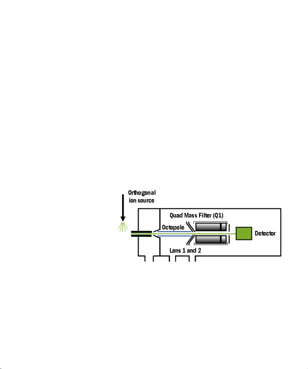
Design for a single quadrupole mass spectrometer
Mass spectrometry is based on the analysis of ions moving
through a vacuum.
The ionization of a sample occurs in the ion source that is
shown, schematically, on the left. The ions are analyzed by
a mass analyzer (mass filter) that controls the motion of the
ions as they travel to the detector to be converted into actual
signals.
Figure 1 Schematic for single quadrupole mass spectrometer
m/z – mass/charge ratio The quadrupole mass analyzer consists of four parallel rods to
which specific DC and RF voltages are applied. These rods filter
out all ions except those of one or more particular m/z values as
determined by the voltages applied.
14 Agilent 6400 Series Triple Quad LC/MS Concepts Guide
Page 15
Inner Workings – Triple Quadrupole MS versus Single Quadrupole MS 2
External Ionization Source
Quadrupole Mass Filter
Detector
How a single quadrupole mass spectrometer works
The RF is applied to all four rods, but the negative (–) rods are
180 degrees out of phase with the positive (+) rods. The rods are
labeled + and – in reference to the DC voltages applied to them.
All ions that comprise the sample are generated at the source.
However, when a specific set of voltages is applied, only ions of
the corresponding m/z value may pass through the quadrupole
to reach the detector. As the voltages are increased to other
values, ions with other m/z values are allowed to pass through.
A full MS scan is obtained by increasing the DC and RF voltages
applied to the four rods over an expanded range of values.
How a single quadrupole mass spectrometer works
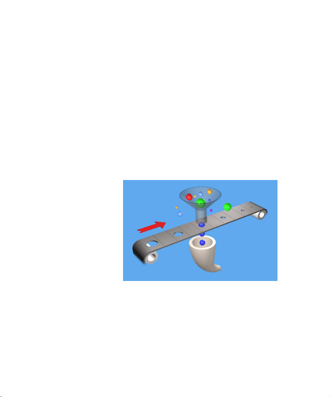
A diagrammatic model can be used to illustrate the concept of
how a single quadrupole instrument works. See Figure 2.
Agilent 6400 Series Triple Quad LC/MS Concepts Guide 15
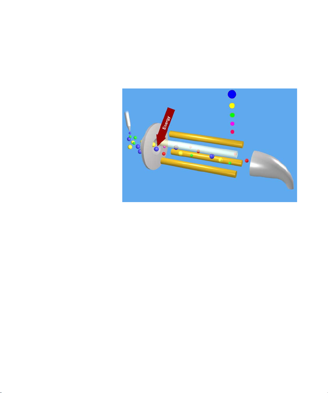
Figure 2 Conceptual model of a single quadrupole mass spectrometer
In the model,
• All of the ions contained in a sample are formed in the
external ionization source and collected in a funnel. The balls
of different colors and sizes represent different ions having
different m/z values.
Page 16

2 Inner Workings – Triple Quadrupole MS versus Single Quadrupole MS
How a single quadrupole mass spectrometer works
• The quadrupole mass analyzer is represented by a moving
belt that serves to filter the ions as they pass through
openings of various sizes. The ions pass from the funnel,
through the filter, to the detector. Although in this image,
ions that are smaller might fit through the openings, a
quadrupole mass analyzer filters the ions so that only the
“correct” ions pass through to the detector.
• The detector is represented by the collecting funnel below
the filtering belt.
As the belt (the analyzer) moves, or the voltages on the rods are
changed, ions with different m/z values are filtered through the
mass spectrometer.
As the analyzer moves from a small m/z value to increasingly
larger values, a full MS scan is created.
SIM – Selected Ion Monitoring If the belt does not move, the detector continues to monitor the
same single m/z value over the entire scan period. This type of
analysis is known as SIM. It is the most sensitive operating
mode for a single quadrupole mass spectrometer.
The scan period is selected (fixed) by the user. The user may set
the dwell time to scan a specific mass range (e.g. m/z 50 to
1000) or to remain on one selected ion (SIM) or to move to
several selected ions during the scan period. The quadrupole
mass filter is not scanned in this mode. The required RF/DC
voltages are often set to filter a single mass at one time.
For comparison, see “How a triple quadrupole mass
spectrometer works" on page 27.
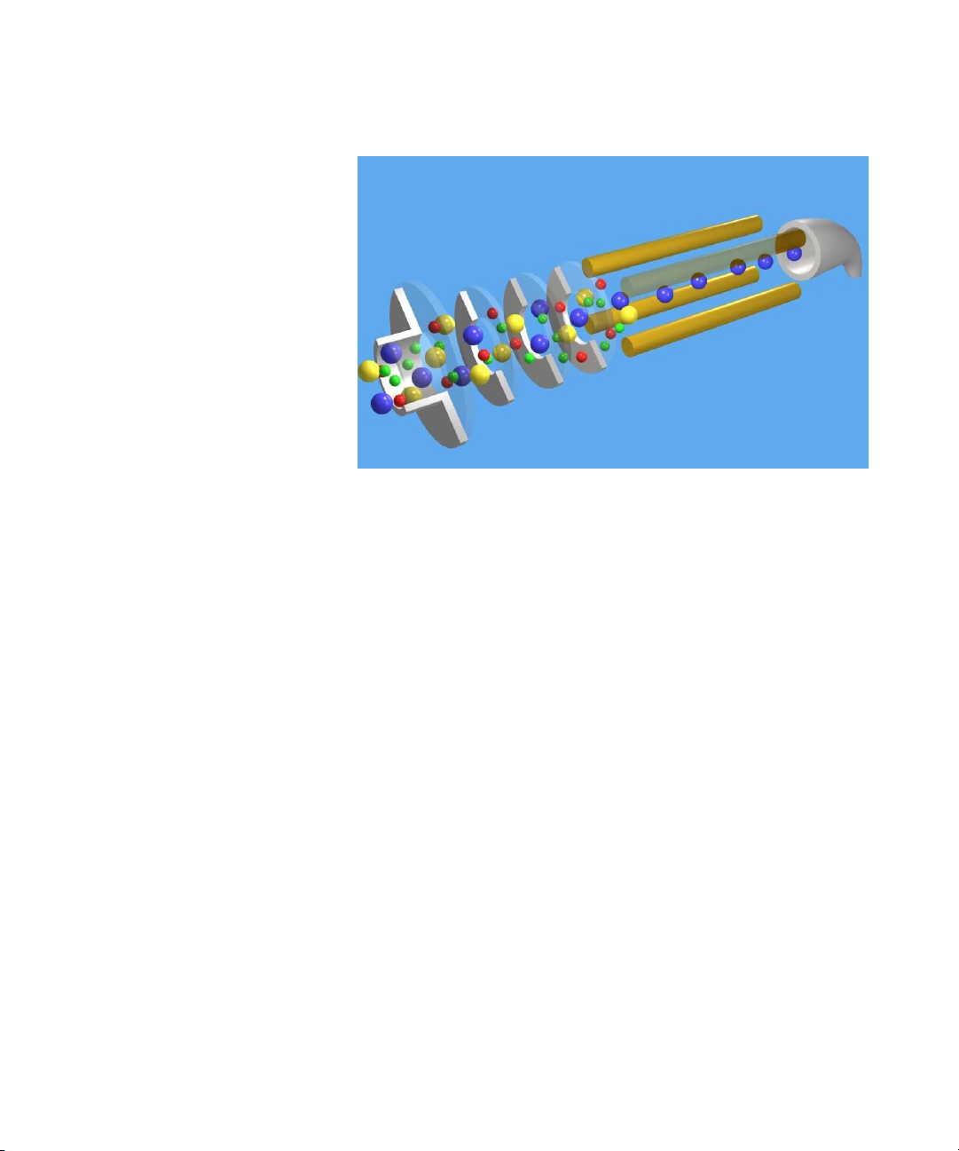
Single quadrupole: SIM
To obtain the best sensitivity or quantitation, the single
quadrupole is operated in SIM mode (Figure 3). The duty cycle
is the measure of the instrument’s time actually devoted to
measuring signals. In SIM mode, the single quadrupole analyzes
the signal of a specific m/z ion almost all of the time. This
results in nearly 100% acquisition during the duty cycle.
16 Agilent 6400 Series Triple Quad LC/MS Concepts Guide
Page 17
Inner Workings – Triple Quadrupole MS versus Single Quadrupole MS 2
API Source
Ion Guide
Detector
Quadrupole Mass Analyzer
How a single quadrupole mass spectrometer works
Figure 3 Single quadrupole: SIM
In this example,
1 All of the ions (+, -, and neutrals) are formed in the API
source.
2 Ion optics guide the ions to the quadrupole mass analyzer.
The Agilent Ion Guide is an octopole filter of eight equally
spaced rods.
3 In the analyzer, only ions of a particular m/z value,
represented by blue balls, are allowed to pass through to the
detector.
4 The detector completes the analysis.
This system has several advantages:
• provides the best sensitivity for quantitation
• increases selectivity
• improves chromatographic specificity
• provides no structural information
Agilent 6400 Series Triple Quad LC/MS Concepts Guide 17
Page 18
2 Inner Workings – Triple Quadrupole MS versus Single Quadrupole MS
API Source
Detector
Quadrupole Mass Analyzer
How a single quadrupole mass spectrometer works
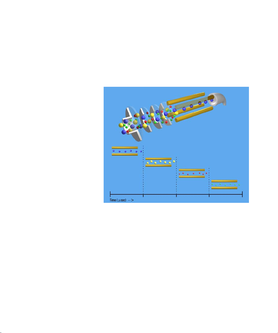
Single quadrupole: Full Scan MS
In a full MS scan, the quadrupole serves as a mass filter over
time, and a scan is carried out by stepping through increasing
DC and RF voltages. This provides filtering through the
corresponding m/z values across a mass spectrum. See Figure 4.
Figure 4 Single quadrupole: Full scan MS
The full scan MS mode is less sensitive because the duty cycle
for each m/z is considerably less than 100%. The quadrupole
mass analyzer scans sequentially, passing each m/z in the
selected mass range to the detector.
A full scan MS is still a useful mode of operation because it
shows all of the ions that are being formed in the ion source.
This is useful for developing SIM acquisitions but also alerts
analysts to other compounds co-eluting with compounds of
interest.
18 Agilent 6400 Series Triple Quad LC/MS Concepts Guide
Page 19
Inner Workings – Triple Quadrupole MS versus Single Quadrupole MS 2
m/z 325 Analyte Precursor
m/z 325 Matrix Precursor
m/z 202 Matrix Precursor
m/z 184 Product Ion
m/z 124 Product Ion
Detector
API Source
How a single quadrupole mass spectrometer works
What about fragment ions?
Full scans with a single quadrupole instrument can also be used
to study fragment ions. See Figure 5.
Figure 5 Fragment ions with single quadrupole MS
The diagram shows that fragment ions, also known as product
ions, are formed by fragmenting or breaking apart precursor
ions. Precursor ions formed in the ion source travel through the
mass analyzer without change, unless extra energy is applied to
their motion in a region where fragmentation can occur.
This fragmentation or collisionally induced dissociation (CID)
can be carried out in a low pressure region between the ion
source and the mass analyzer. The ion source is under
atmospheric pressure, while the mass analyzer is at a much
lower pressure because it has been evacuated of gas with
a vacuum pump.
On the Agilent single quadrupole mass spectrometer, this region
is between the capillary exit and the skimmer, where the gas
pressure is about 2 Torr, or about three orders of magnitude
below atmosphere pressure (760 Torr). Under normal
operation, a voltage is applied across this region to keep the
Agilent 6400 Series Triple Quad LC/MS Concepts Guide 19
Page 20
2 Inner Workings – Triple Quadrupole MS versus Single Quadrupole MS
How a single quadrupole mass spectrometer works
ions passing through to continue on to the mass analyzer. Even
if these ions collide with the gas molecules in this region, they
usually do not have enough energy to fragment.
CID – Collisionally Induced
Dissociation
However, as the voltage is increased, the ions have more
translational energy. Then, if the ions run into gas molecules,
the collisions convert the translational energy into molecular
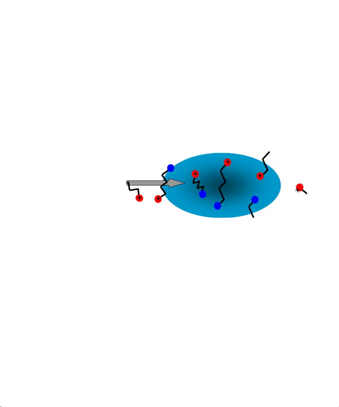
vibrations that can cause the ions to fragment (Figure 6). This is
collisionally induced dissociation (CID). Even though this
fragmentation does not occur where the ions are formed at
atmospheric pressure, it’s a tradition to call this type of
fragmentation “In-source CID.”
Figure 6 Ion fragmentation caused by collision-induced dissociation
A single quadrupole mass spectrometer cannot be used to do
MS/MS because all of the ions formed in the ion source are
transferred to the quadrupole whether fragmented or not. At
the end when the mass analyzer filters the ions, it is not
possible to identify which product ions came from which
precursor ions.
A triple quadrupole mass spectrometer can do MS/MS, with
fragmentation within its collision cell as described in the next
section.
20 Agilent 6400 Series Triple Quad LC/MS Concepts Guide
Page 21

Inner Workings – Triple Quadrupole MS versus Single Quadrupole MS 2
Triple quadrupole MS operation
Be sure to read the previous section on the concepts behind the
operation of a single quadrupole mass spectrometer.
Understanding these concepts helps you understand the
operation of the triple quadrupole mass spectrometer.
Design of the Agilent Triple Quadrupole MS
The triple quadrupole mass spectrometer consists of an ion
source, enhanced desolvation technology, followed by ion optics
that transfer the ions to the first quadrupole positioned to the
right of it. A diagram of some of the current Triple Quadrupole
LC/MS products is shown in Figure 7 on page 22. The Agilent
6430 is shown in Figure 8 on page 23.
Triple quadrupole MS operation
Agilent 6400 Series Triple
Quadrupole System
6420 • Includes one turbo pump and one rough pump
6430 • Adds an additional turbo pump
6460 • Includes Agilent Jet Stream Technology
6490 • Includes iFunnel technology (Agilent Jet
Highlights
• Includes resistive capillary
• Can upgrade to a 6430
• Improves pumping in vacuum stage 2
• Updates collision cell lenses
• Can upgrade to a 6460
• Includes 3,000 m/z Q1 and Q2 quadrupoles
Stream, hexabore capillary, and high
pressure/low pressure ion funnels)
• Adds additional rough pump for ion funnel
• Includes high throughput quadrupole driver
electronics
• Includes curved collision cell assembly
• Has a smaller footprint
Agilent 6400 Series Triple Quad LC/MS Concepts Guide 21
Page 22
2 Inner Workings – Triple Quadrupole MS versus Single Quadrupole MS
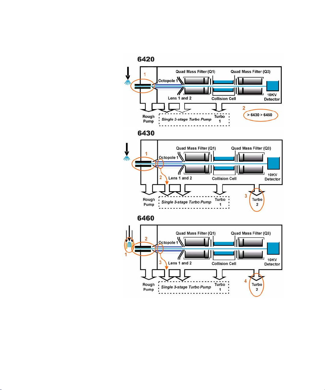
Circled areas indicate enhancements
Design of the Agilent Triple Quadrupole MS
Figure 7 Innovative Enhancements in the 6420, 6430 and 6460
22 Agilent 6400 Series Triple Quad LC/MS Concepts Guide
Page 23

Inner Workings – Triple Quadrupole MS versus Single Quadrupole MS 2
Circled areas indicate enhancements
Innovative Enhancements in the 6490 Triple Quadrupole
Figure 8 Innovative Enhancements in the 6490
The quadrupole consists of four parallel hyperbolic rods
through which selected ions are filtered before reaching
a collision cell where they are fragmented. The collision cell is
typically called the second quadrupole, but in the case of the
6460, geometrically it is actually a hexapole filled with nitrogen,
the same gas used in the ion source. In the 6490, the collision
cell is a hexapole field axial focusing curved collision cell.
Agilent 6400 Series Triple Quad LC/MS Concepts Guide 23
Innovative Enhancements in the 6490 Triple Quadrupole
The fragment ions formed in the collision cell are then sent to
the third quadrupole for a second filtering stage to enable
a user to isolate and examine multiple precursor to product ion
transitions (MRMs).
The iFunnel Technology encompasses the first three
enhancements to the 6490: a hexabore capillary, the Dual Ion
Funnel technology and the Curved Collision Cell. The fourth
enhancement is improved quadrupole drive electronics.
Page 24

2 Inner Workings – Triple Quadrupole MS versus Single Quadrupole MS
Innovative Enhancements in the 6490 Triple Quadrupole
Figure 9 The iFunnel Technology
Ions are generated using an electrospray ion source where the
analyte is simultaneously ionized and desolvated from the
liquid matrix. The iFunnel includes the application of Agilent
Jet Stream Technology (first introduced with the 6460) which
improves sensitivity via thermal gradient focusing and
enhanced desolvation.
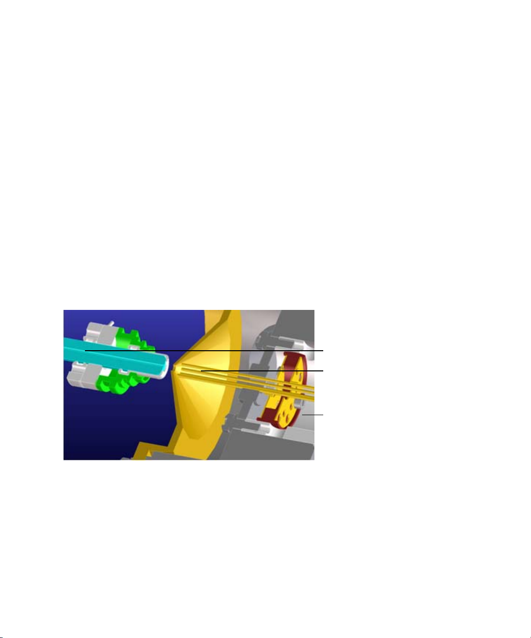
The first innovative enhancement is the use of a short hexabore
capillary. It has 6 capillary inlets and samples up to 10X more
ion rich gas from the source. It captures the majority of the gas
from the source region. See Figure 10. The hexabore capillary
transmits a high gas/ion volume into the ion optic system.
Figure 10 Hexabore capillary
24 Agilent 6400 Series Triple Quad LC/MS Concepts Guide
Page 25

Inner Workings – Triple Quadrupole MS versus Single Quadrupole MS 2
Innovative Enhancements in the 6460 Triple Quadrupole
The Dual Ion Funnel (DIF) technology is the second
enhancement. The DIF technology removes the gas and neutral
noise but captures the ions. It also extends the turbo pump’s
lifetime. The Dual Ion Funnel technology can transmit ions
efficiently at as high a pressure as possible. The first ion funnel
has a pressure between 7 and 14 torr. The second ion funnel is a
low pressure ion funnel (1 to 3 torr). The ion funnel works by
having the RF voltage focus the ions to the center and having
the DC voltage accelerate the ions to the exit. See Figure 11.
Figure 11 The Dual Ion Funnel technology
The hexapole field axial focusing curved collision cell is the
third enhancement. It includes a tapered cell structure for
increased ion acceptance at the entrance. Its structure reduces
the ionizer generated noise.
The fourth enhancement is the improved quadrupole drive
electronics. The higher drive frequency produces more ion
motion cycles in the quadrupole mass filter. More ion motion
cycles gives higher mass resolution. You can tune a 6490 to 0.4
m/z. The higher drive frequency does reduce the mass range to
1400 m/z.
Innovative Enhancements in the 6460 Triple Quadrupole
Ions are generated using an electrospray ion source where the
analyte is simultaneously ionized and desolvated from the
liquid matrix. The first of five (5) innovative Agilent
enhancements is found in the application of Agilent Jet Stream
Technology (denoted as 1 on the 6460 in Figure 7 on page 22)
which improves sensitivity via thermal gradient focusing and
enhanced desolvation.
Agilent 6400 Series Triple Quad LC/MS Concepts Guide 25
Page 26

2 Inner Workings – Triple Quadrupole MS versus Single Quadrupole MS
Innovative Enhancements in the 6460 Triple Quadrupole
The desolvated ions then enter the mass spectrometer via an
innovative resistive and highly inert capillary transfer tube
(denoted as 2 on the 6460 in Figure 7 on page 22) that improves
ion transmission and allows virtually instantaneous polarity
switching.
Further improving the sensitivity is improved pumping in
vacuum stage 2 that allows more pumping speed behind the
skimmer and improved ion capturing by first octopole (denoted
as 3 on the 6460 in Figure 7). The ions next pass through optics
and into the first quadrupole analyzer. The quadrupole analyzer
consists of four parallel hyperbolic rods through which selected
ions based on their mass to charge ratio are filtered.
The ions passing through the first quadrupole analyzer are then
directed through an improved collision cell where they are
fragmented. The collision cell is typically called the second
quadrupole, but in this case, geometrically it is actually a
hexapole filled with nitrogen, the same gas that is used as the
drying gas. Agilent innovation has led to the design of a
collision cell that has axial acceleration for high speed MS/MS
analysis (denoted as 4 on the 6460 in Figure 7). Fragment ions
formed in the collision cell are then sent to the third
quadrupole for a second filtering stage to enable a user to
isolate and examine product ions with respect to precursor
ions.
Finally, the ions that pass through the third quadrupole are
detected using a high energy detector. A second turbo pump has
been added (denoted as 5 on the 6460 in Figure 7) to increase
pumping speed and improve the vacuum which will further
improve the signal to noise and enhance the limit of detection of
the triple quadrupole.
26 Agilent 6400 Series Triple Quad LC/MS Concepts Guide
Page 27

Inner Workings – Triple Quadrupole MS versus Single Quadrupole MS 2
Innovative Enhancements in the 6430 Triple Quadrupole
Innovative Enhancements in the 6430 Triple Quadrupole
The 6430 Triple Quadrupole has many of the innovative
enhancements that are included in the Agilent 6460 Triple
Quadrupole.
• The same resistive capillary transfer tube (denoted as 1 on
the 6430 in
• Improved pumping in vacuum stage 2 (denoted as 2 on the
6430 in
• A second turbo pump has been added (denoted as 3 on the
6430 in
Figure 7 on page 22)
Figure 7)
Figure 7)
Innovative Enhancements in the 6420 Triple Quadrupole
The 6420 Triple Quadrupole has some of the innovative
enhancements that are included in the Agilent 6430 Triple
Quadrupole.
• The same resistive capillary transfer tube (denoted as 1 on
the 6420 in
• The 6420 Triple Quadrupole can be upgraded to a 6430 and
then to a 6460 Triple Quadrupole. (denoted as 2 on the 6420
in
Figure 7 on page 22)
Figure 7 on page 22)
How a triple quadrupole mass spectrometer works
Quadrupoles provide a user with the capability to do MS/MS in
several ways (see Figure 12).
Agilent 6400 Series Triple Quad LC/MS Concepts Guide 27
Page 28

2 Inner Workings – Triple Quadrupole MS versus Single Quadrupole MS
External
Ionization
Precursor
Quad Filter
Q1
Collision
Cell
Detector
Product
Quad Filter
Q3
How a triple quadrupole mass spectrometer works
Figure 12 Conceptual model of a triple quadrupole mass spectrometer:
With SIM, MS1 (Q1) and MS2 (Q3) are set at a single m/z,
while with Full Scan MS/MS, MS1 (Q1) is set at a single m/z
and MS2 (Q3) is scanned.
Representing the quadrupole mass analyzers as moving belts,
a collision cell can be placed between the belts to fragment the
ions. The first belt can be fixed to select which precursor ion
travels to the collision cell. Different types of collision cells can
be used.
The collision cell can be another quadrupole, a hexapole (six
rods like the one used in the Agilent 6400 Series Triple
Quadrupole LC/MS), an octopole (eight rods), or even a
transverse wave guide.
Whichever geometry is used, a collision gas is required—an
inert, non-reactive gas such as nitrogen or argon. Nitrogen is
used here. In addition, the voltages applied to the collision cell
must be different from those applied to the quadrupoles to
enhance the movement of all of the product ions toward the
third quadrupole.
28 Agilent 6400 Series Triple Quad LC/MS Concepts Guide
Page 29

Inner Workings – Triple Quadrupole MS versus Single Quadrupole MS 2
How a triple quadrupole mass spectrometer works
In this example, a precursor ion is selected using the first
quadrupole and is sent to the collision cell for fragmentation.
The fragments are scanned through the third quadrupole
resulting in a product-ion scan MS/MS. Since the fragment ions
are pieces of the precursor, they represent portions of the
overall structure of the precursor molecule. A triple quadrupole
instrument can be used in this way to identify a compound’s
fingerprint.
A full scan MS/MS using a triple quadrupole MS is also not the
most sensitive mode for the same reason that a full scan MS
using a single quadrupole is not the most sensitive mode of
operation possible (first belt remains steady; second belt
moves). The most sensitive mode of operation for the triple
quadrupole MS instrument is to fix both belts and only monitor
a specific precursor ion and a specific product ion. This mode is
called selected reaction monitoring or SRM.
In normal operation, a triple quadrupole MS instrument
involves running multiple SRMs for the same precursor ions.
This is called multiple reaction monitoring or MRM.
Agilent 6400 Series Triple Quad LC/MS Concepts Guide 29
Page 30

2 Inner Workings – Triple Quadrupole MS versus Single Quadrupole MS
How Dynamic MRM works
How Dynamic MRM works
Dynamic MRM is a scan type that has a single continuous Time
Segment and up to 4000 transitions in the Scan Segments table.
You can add a Time segment that sets the divert valve to waste.
At run time, these transitions are automatically separated into
multiple “MRM Tables” according to the retention time window
for each transition. These MRM tables consist of the transitions
that are overlapping in retention time and can contain up to 200
transitions each. These tables are not shown in the user
interface.
Dynamic MRM includes the columns Ret Time (Retention Time)
and Delta Ret Time (Delta Retention Time). Ret Time is the
transition retention time. Each transition is acquired from Ret
Time - 1/2*(Delta Ret Time) to Ret Time + 1/2 * (Delta Ret
Time). Ret Time and Delta Ret Time are entered in minutes.
Abundance data is acquired starting at time “t” for duration
“delta t”. The first MRM table in the example below acquires
transitions “abcdef”. The second MRM table acquires transitions
from “defghi”, and so on.
Figure 13 Automatically determining dynamic MRM tables.
The benefit of Dynamic MRM is to allow longer dwell times by
performing MRM transitions around the elution time of the
compound and not continuously throughout the chromatogram.
30 Agilent 6400 Series Triple Quad LC/MS Concepts Guide
Page 31

Inner Workings – Triple Quadrupole MS versus Single Quadrupole MS 2
How Dynamic MRM works
The MassHunter Data Acquisition software, the SmartCard
firmware, the Digital Signal Processor and the MS Hardware all
are involved in the dynamic MRM algorithm.
1 MassHunter Data Acquisition Software
A list of transitions/parameters (up to 4000) are entered by
the user. Based on delta retention time, retention time, dwell
time and cycle time, the Data Acquisition software creates a
lookup recipe that will group transitions in the digital signal
processor into small MRM tables (up to 1000+ tables). Each
table has the same cycle time. MRM tables are similar to
“Time Segments” but have fewer transitions enabling the data
file to have more data points per peak.
A transition peak may contain data points from more than
one MRM table. A peak will look like a peak because the
abundance value at each data point is normalized by “dwell”
time.
2 SmartCard Firmware
The SmartCard Firmware sends the transition list to the
Digital Signal Processor (DSP) memory. It also sends the
lookup recipe to the DSP memory.
Peak abundance data returning from the DSP is Burst/Time
filtered in the SmartCard firmware. The data is sent back to
the Data Acquisition software which stores the data in an
MRM data file which both the Qualitative Analysis program
and the Quantitative Analysis program can open.
3 Digital Signal Processor (DSP)
A dynamic MRM run is controlled entirely by the Digital
Signal Processor firmware.
When a Dynamic MRM Run starts, the lookup recipe starts
creating MRM tables by selecting transitions from the list and
then executing them. When the stop time of the MRM table is
reached, the next table is created and started. There is
minimal delay between changing MRM tables in the DSP and
no data is lost. This process continues until all MRM tables
have been run. At the end of the run, background scan
continues in MRM mode.
Agilent 6400 Series Triple Quad LC/MS Concepts Guide 31
Page 32

2 Inner Workings – Triple Quadrupole MS versus Single Quadrupole MS
How Dynamic MRM works
For each individual transition, the DSP sends MS parameters
to the hardware in the form of address/data pairs.
4 MS Hardware
For each transition, the DSP address/data pair sets the
hardware quadrupoles and other parameters.
After the MS hardware parameters are set for each
transition, the MS takes an integrated abundance
measurement at the selected ion and sends the unfiltered
abundance data back to SmartCard firmware in the form of a
structure containing header and abundance information.
32 Agilent 6400 Series Triple Quad LC/MS Concepts Guide
Page 33

Inner Workings – Triple Quadrupole MS versus Single Quadrupole MS 2
How Triggered Dynamic MRM works
How Triggered Dynamic MRM works
Triggered Dynamic MRM occurs when criteria for primary
MRMs trigger confirmatory (secondary) MRMs to be acquired
for a compound. If the abundances of the Primary MRMs are
higher than the set thresholds and other criteria are met, then
the confirmatory (or secondary) MRMs are acquired. You can
have multiple primary MRMs per compound, and you can
specify up to two of these as Trigger MRMs for each compound.
You can also have multiple secondary transitions for each
compound. All transitions with the same Compound Name
belong to the same compound.
Figure 14 Explanation of threshold for Triggered Dynamic MRM
In Figure 14, only the Trigger MRMs are acquired until the
abundance of each of the Trigger MRMs is higher than the
thresholds you entered. After the abundances for each Trigger
MRM is higher than the threshold, then the secondary
transitions may be acquired, depending on the Trigger
Entrance Delay, Trigger Delay and Trigger Window. These
additional criteria are discussed in the next section.
In the Scan Segments table, you specify which transitions are
Primary transitions by marking the check box in the Primary
column. These transitions are monitored within the peak
retention time window specified for the compound. You also can
specify one or two of these primary transitions as Trigger MRMs
by marking the check box in the Trigger column. Any transition
Agilent 6400 Series Triple Quad LC/MS Concepts Guide 33
Page 34

2 Inner Workings – Triple Quadrupole MS versus Single Quadrupole MS
How Triggered Dynamic MRM works
that is not marked as a Primary transition but that has the
same compound name as a Primary transition is a secondary
transition for the compound.
You specify a threshold for each Trigger MRM. If the abundances
for the Trigger MRM transitions are greater than the specified
thresholds and the other triggering conditions are met, then the
secondary transitions are acquired. If you have two Trigger
MRM transitions for a compound, then the abundances for both
of these transitions must be greater than or equal to their
thresholds for the secondary transitions to be acquired.
These secondary transitions are acquired for the Number of
Repeats specified. If the trigger transition drops below the
threshold, and rises again above the threshold within the peak
retention time window, the secondary ions are triggered again.
If the retention time window ends, the software stops acquiring
these secondary transitions even if they have not been acquired
for the Number of Repeats specified. The software also stops
acquiring the Primary MRMs when the peak retention time
window ends.
Triggers may happen at different time/abundance
Examination of the abundance of the primary transition(s) and
the decision to sample the additional secondary transitions
happens in real time, on a cycle-to-cycle basis, using unfiltered
data. However, in general, the data stored to disk is the result of
using time filtering (data for a given cycle is smoothed using
data from cycles before and after the given cycle). Therefore,
because of this difference, triggering may appear to start a cycle
or two late, or may appear to trigger at an abundance
significantly different from the trigger threshold set in the
program. Usually, this is not a concern as long as triggering
occurs somewhere during peak elution.
The sample matrix may also affect where triggering occurs. If
triggering is set using a standard made in solvent, the triggering
thresholds may be set to low abundance values. If a sample is
run in matrix where there's a significant response at the trigger
transition due to the matrix, triggering will happen
prematurely. It is preferable to use matrix-matched standards
for calibration and update of the triggering parameters.
34 Agilent 6400 Series Triple Quad LC/MS Concepts Guide
Page 35

Inner Workings – Triple Quadrupole MS versus Single Quadrupole MS 2
How Triggered Dynamic MRM works
Other triggering conditions for each compound
Figure 15 Example of Trigger Window
Trigger Entrance Delay The Trigger Entrance Delay is the number of scans to skip
after the thresholds for the Trigger transitions have been met
within the Trigger Window. If the Trigger Entrance Delay is 2
and the other trigger conditions are met at scan 200, then only
the primaries are acquired at scans 201 and 202 (the next 2
scans). Primary and secondary transitions are acquired starting
at scan 203.
Trig ger D el a y The Trigger Delay is the number of scans to skip between
acquiring each of the secondary transitions. If the Trigger
Entrance Delay is 0, the Trigger Delay is 1 and the Repeats is
set to 3 and the other trigger conditions are met at scan 200,
then the secondary transitions are acquired at scan 201, scan
203 and scan 205. Only the primary transitions are acquired at
scans 202 and 204. If the Trigger Delay is set to 2 in the
example above, then the secondary transitions are acquired at
scan 201, scan 204, and scan 207. Only the primary transition
are acquired at scans 202, 203, 205 and 206.
Trig g e r Win d ow The Trigger Window can be a narrower window within the
Peak Retention Time window. The thresholds for the trigger
transitions are only monitored within the Trigger Window. By
default, the Trigger Window is set to 0 which means the
Trigger Window is the same time as the Peak Retention Time
window. The value you enter for the Trigger Window is the full
width of the window. The Trigger Window is from Ret Time 1/2*(Trigger Window) to Ret Time + 1/2 * (Trigger Window).
Ret Time and Trigger Window are entered in minutes.
Agilent 6400 Series Triple Quad LC/MS Concepts Guide 35
Page 36

2 Inner Workings – Triple Quadrupole MS versus Single Quadrupole MS
How Triggered Dynamic MRM works
Example of Triggered MRM with four compounds
Figure 16 Triggered MRM in the Scan Segments table
• The Scan type is set to Dynamic MRM and the Triggered
check box is marked. Repeats is set to 3.
• This Scan segments table has four different compounds.
• Each of these compounds has at least one Trigger transition.
You do not need to specify a Trigger transition for each
compound. If you do not, no secondary transitions are
triggered.
• Sulfachloropyridazine has two primary transitions and one
of these is the trigger transition.
• Sulfamethazine has two primary transitions and both of
these are trigger transitions.
• A compound does not have to have secondary transitions.
• If a scan is outside of the Trigger Window, then the
secondary transitions are not acquired.
• All of these compounds do have secondary transitions.
The secondary transitions for sulfadimethoxine are
311.1 m/z - > 156 m/z and 311.1 m/z -> 108 m/z.
• If a scan is outside of the Peak Retention Time window, then
the primary and the secondary transitions are not acquired.
36 Agilent 6400 Series Triple Quad LC/MS Concepts Guide
Page 37

Inner Workings – Triple Quadrupole MS versus Single Quadrupole MS 2
How Triggered Dynamic MRM works
• For sulfachloropyridazine, if the abundance of the primary
trigger transition (285 m/z -> 197 m/z) is greater than 800 at
scan 80, then because the Trigger Entrance Delay is 2,
secondary transitions are acquired starting at scan 83. Only
the primary transitions are acquired at scan 81 and scan 82.
• For sulfadimethoxine, if the abundance of the primary
trigger transition (311.1 m/z -> 245.1 m/z) is greater than
1000 at scan 200, then because the Trigger Delay is 1, the
secondary transitions are acquired at scan 201, scan 203, and
scan 205. Only the primary transitions are acquired at scan
202 and scan 204.
• For sulfamethazine, if the abundance of the first primary
trigger transition (279.1 m/z -> 186 m/z) is greater than 900
counts and the abundance of the second primary trigger
transition (279.1 m/z -> 155.9 m/z) is greater than 1000
counts and the retention time is between 0.6 minutes and 1.0
minutes (the Trigger Window), then the secondary
transitions are acquired. The Trigger Window is set to a
narrower range than the Peak Retention Time window.
• For sulfamethizole, all three trigger conditions are set. So, if
the abundance of the primary trigger transition (285 m/z ->
197 m/z) is greater than 1100 (the threshold) at scan 60 and
the retention time for scan 60 is within the Trigger Window,
then because of the Trigger Entrance Delay is 2, the
secondary transitions are not acquired for the next two scans
(scan 61 and scan 62). Because of the Trigger Delay is 1, the
secondary ions are acquired at scan 63, scan 65 and scan 67.
One scan is skipped after each time you acquire the
secondary ion; only the primary transitions are acquired at
scan 64 and scan 66. If any of these scans are outside of the
Trigger Window, then the secondary transitions are not
acquired for those scans.
Agilent 6400 Series Triple Quad LC/MS Concepts Guide 37
Page 38

2 Inner Workings – Triple Quadrupole MS versus Single Quadrupole MS
How Triggered Dynamic MRM works
38 Agilent 6400 Series Triple Quad LC/MS Concepts Guide
Page 39

Agilent 6400 Series Triple Quadrupole LC/MS System
Concepts Guide
3
Agilent Triple Quadrupole MS and
Sensitivity
How the Agilent Triple Quadrupole MS improves sensitivity 40
Noise reduction 40
Example of chemical noise reduction 43
Linearity of the Agilent 6400 Series Triple Quadrupole MS 45
How each component works to improve sensitivity 46
LC/MS ion sources 49
Front-end ion optics 55
Collision cell 57
Detector 62
Pumping system 63
This chapter shows how the Agilent triple quadrupole mass
spectrometer reduces chemical and electronic noise and how
each component contributes to enhanced instrument
sensitivity.
Agilent Technologies
39
Page 40

3 Agilent Triple Quadrupole MS and Sensitivity
How the Agilent Triple Quadrupole MS improves sensitivity
How the Agilent Triple Quadrupole MS improves sensitivity
Triple quadrupole mass spectrometers exhibit multiple sources
of noise, including noise from all chemical and cluster
backgrounds and electronic noise (Figure 17).
Noise reduction
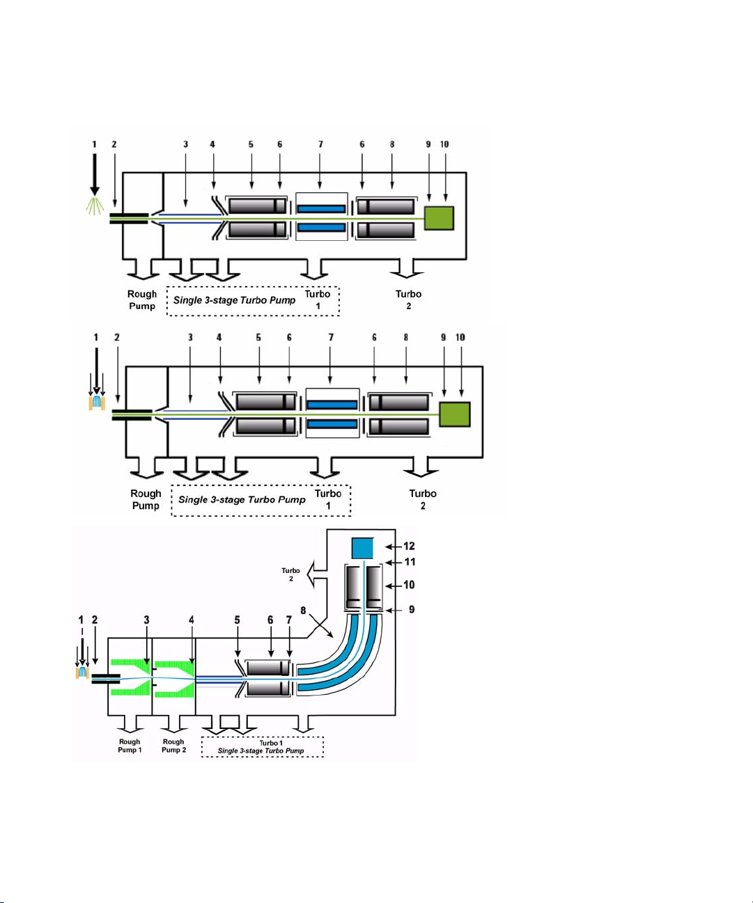
The problem of noise must be addressed at several stages of
the instrumentation from the ion source (1) to the detector
(10) in Figure 17.
40 Agilent 6400 Series Triple Quad LC/MS Concepts Guide
Page 41
Agilent Triple Quadrupole MS and Sensitivity 3
Agilent 6430
Agilent 6460 with
Agilent Jet
Stream
Technology
Agilent 6490 with
Agilent Jet Stream
Technology
Noise reduction
Figure 17 Multiple sources of noise
Agilent 6400 Series Triple Quad LC/MS Concepts Guide 41
Page 42

3 Agilent Triple Quadrupole MS and Sensitivity
Noise reduction
How the Agilent 6400 Series Triple Quadrupole instrument
minimizes noise
1 Agilent’s orthogonal spray sources maximize ionization while
minimizing solvent and matrix noise.
2 This combination of a heated counter-current drying gas,
dielectric capillary and skimmer enhances desolvation while
minimizing chemical noise.
3 RF Octopole ion guide provides high efficiency ion capture
while optimizing wide mass bandwidth ion transmission.
4 L2 RF enhances high mass ion transmission.
5 Quadrupole 1 uses hyperbolic quadrupoles to optimize ion
transmission and spectral resolution.
6 RF quadrupole segment enhances ion transmission into and
out of the collision cell.
Crosstalk is the interference
caused when two signals
become partially superimposed
on each other. In this case residual
product ions can interfere with the
product ion spectrum of a
subsequent MRM experiment.
7 High pressure collision cell with linear acceleration
optimizes MS/MS fragmentation while eliminating crosstalk,
even at very low dwell times. A small diameter high
frequency hexapole assembly assists with capturing and
focusing fragmented ions. For the 6490, the hexapole field
axial focusing curved collision cell includes a tapered cell
structure for increased ion acceptance at the entrance. Its
structure reduces the ionizer generated noise.
8 Quadrupole 2 uses hyperbolic quadrupoles to optimize ion
transmission and spectral resolution.
9 The off-axis matching dual high energy dynode detector with
log amp signal compression permits a high gain with rapid
polarity switching, a long life and low noise. The off-axis
design allows neutrals to pass without hitting the detector.
10 The multiplier has a long life since only electrons impact its
surface, never ions.
42 Agilent 6400 Series Triple Quad LC/MS Concepts Guide
Page 43
Agilent Triple Quadrupole MS and Sensitivity 3
Example of chemical noise reduction
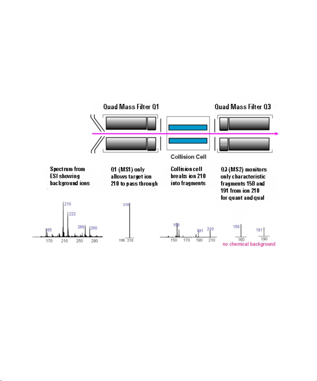
Example of chemical noise reduction
The Agilent 6400 Series Triple Quadrupole mass spectrometer
passes through four transitional steps in translating a signal in
the MRM process (Figure 18).
Figure 18 Multiple reaction monitoring (MRM)
Step 1 The spectrum at the far left represents everything that
is being ionized at the ion source. This example shows the ESI
spectrum of a phenylurea pesticide. A triple quadrupole mass
spectrometer reduces chemical noise for low-level quantitation
in a dirty matrix more than a single quadrupole LC/MS does.
Step 2 This step is accomplished by first selecting the pesticide
of interest at m/z 210 from the co-eluting interferences seen in
the rest of the spectrum. The second spectrum shows the result
after passing through the first quadrupole, or MS1 (Q1).
Agilent 6400 Series Triple Quad LC/MS Concepts Guide 43
Page 44

3 Agilent Triple Quadrupole MS and Sensitivity
Example of chemical noise reduction
Step 3 After MS1 (Q1), fragment ions are generated in the
collision cell. The corresponding MS/MS spectrum is shown
below the collision cell.
Step 4 Particular fragment ions can be selected to pass
through the MS2 (Q3) quadrupole. These are selected for
quantitation and confirmation. For example, the product ion at
m/z 158 is more intense than the product ion at m/z 191.
Therefore, the MRM transition 210 to 158 would be used for
quantitation and the 210 to 191 transition would be used for
confirmation, where the m/z 191 ion is considered a qualifier
ion.
The second stage of selectivity using the MS2 (Q3) quadrupole
removes much of the chemical background. Typically, the
chance of an isobaric interference at the same exact mass as the
fragmentation ion is remote.
44 Agilent 6400 Series Triple Quad LC/MS Concepts Guide
Page 45

Agilent Triple Quadrupole MS and Sensitivity 3
Linearity of the Agilent 6400 Series Triple Quadrupole MS
Linearity of the Agilent 6400 Series Triple Quadrupole MS
Analyses of verapamil show the following linear dynamic range:
6490: six orders of magnitude (Figure 19)
6460, 6430, 6420: five orders of magnitude
Figure 19 Verapamil results - Calibration Curve 100 Attograms to 100 Picograms on-column,
Six orders of magnitude of linear dynamic range (log-log plot)
acquired with Agilent 6490 Triple Quadrupole with Agilent Jet Stream Technology
Agilent 6400 Series Triple Quad LC/MS Concepts Guide 45
Page 46

3 Agilent Triple Quadrupole MS and Sensitivity
How each component works to improve sensitivity
How each component works to improve sensitivity
This section describes in more detail how each of the
components of the Agilent 6400 Series Triple Quadrupole MS
contributes to reducing noise (Figure 17).
Agilent iFunnel Technology
Agilent’s iFunnel Technology which is available on the Agilent
6490 Triple Quadrupole consists of the Agilent Jet Stream
technology, the Hexabore Capillary and the Dual Ion Funnel.
The Agilent Jet Stream technology is discussed below. The
Hexabore Capillary samples up to 10 times more ion rich gas
from the source. It captures the majority of the gas from the
source region. The Dual Ion Funnel (DIF) technology removes
the gas but captures the ions. It also removes the neutral noise.
Figure 20 Agilent 6490’s iFunnel technology
46 Agilent 6400 Series Triple Quad LC/MS Concepts Guide
Page 47

Agilent Triple Quadrupole MS and Sensitivity 3
Figure 21 The Ion Funnel
Agilent Jet Stream Technology
Agilent Jet Stream Technology enhances analyte desolvation by
collimating the nebulizer spray and creating a dramatically
“brighter signal.” The addition of a collinear, concentric,
super-heated nitrogen sheath gas (Figure 22) to the inlet
assembly significantly improves ion drying from the
electrospray plume and leads to increased mass spectrometer
signal to noise allowing the triple quadrupole to surpass the
femtogram limit of detection.
Agilent Jet Stream Technology
Agilent 6400 Series Triple Quad LC/MS Concepts Guide 47
Page 48
3 Agilent Triple Quadrupole MS and Sensitivity
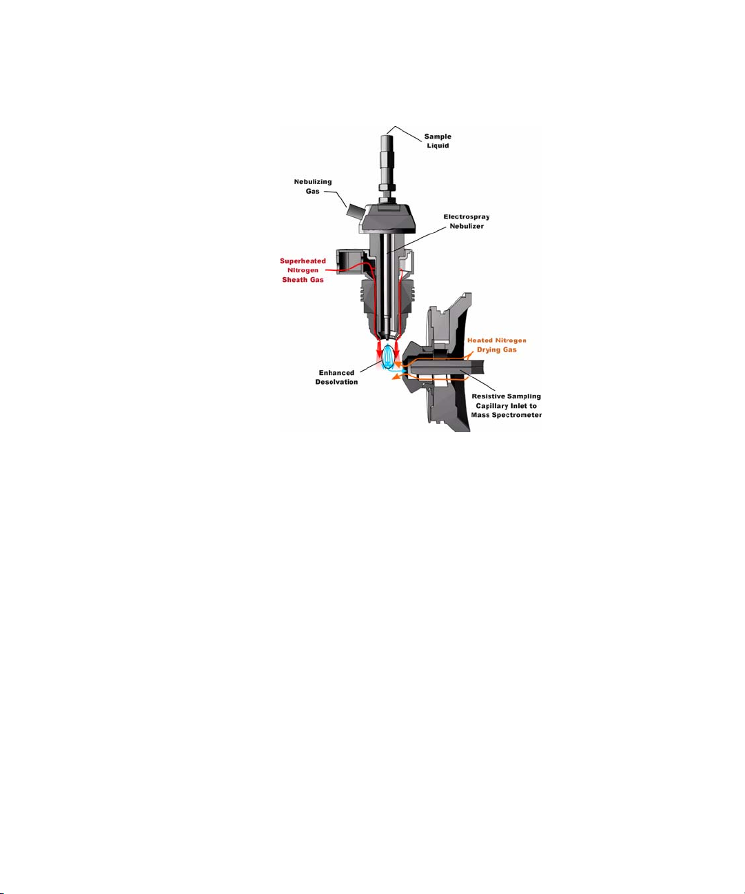
Agilent Jet Stream Technology
Figure 22 Electrospray Ion Source with Agilent Jet Stream Technology
Agilent Jet Stream thermal gradient focusing consists of a
superheated nitrogen sheath gas that is introduced collinear
and concentric to the pneumatically assisted electrospray.
Thermal energy from the superheated nitrogen sheath gas is
focused to the nebulizer spray producing the most efficient
desolvation and ion generation possible. The enhanced
molecular ion desolvation results in more ions entering the
sampling capillary as shown in Figure 22 and concomitant
improved signal to noise. Parameters for the Agilent Jet Stream
Technology are the superheated nitrogen sheath gas
temperature and flow rate and the nozzle voltage.
The capillary in the 6490A is a resistive capillary that improves
ion transmission. It has 6 capillary inlets and samples up to 10X
more ion rich gas from the source.
48 Agilent 6400 Series Triple Quad LC/MS Concepts Guide
Page 49

The capillary in the 6460A is a resistive capillary that improves
ion transmission and allows virtually instantaneous polarity
switching. It is the same, proven capillary that is used in the
fast polarity switching version of Agilent's single quadrupole
product.
LC/MS ion sources
Agilent provides a choice of four ion sources to use with its
triple quadrupole mass spectrometer: ESI, APCI, APPI and MMI.
You ca n a l so us e t he HP L C -Chi p .
This section describes how the different ion sources affect
sensitivity.
ESI ion source design
The orthogonal source reduces the introduction of unwanted
sample components that interfere with analysis. The advanced
nebulizer design produces a uniform droplet size, which
ensures maximum sensitivity. Since the source is at ground, the
source is safe to use and has the advantage of reducing solvent
cluster background (Figure 23).
Agilent Triple Quadrupole MS and Sensitivity 3
LC/MS ion sources
Figure 23 Orthogonal introduction and electrospray ionization
Agilent 6400 Series Triple Quad LC/MS Concepts Guide 49
Page 50

3 Agilent Triple Quadrupole MS and Sensitivity
LC/MS ion sources
The Agilent 6490 Triple Quadrupole has a Hexabore Capillary
which samples up to 10 times more ion rich gas from the source.
The capillary in the 6460A, the 6430A and the 6420A is a
resistive capillary that improves ion transmission and allows
virtually instantaneous polarity switching. It is the same,
proven capillary that is used in the fast polarity switching
version of Agilent's single quadrupole product.
For the Agilent 6410 Triple Quadrupole, the capillary is glass,
dielectric “cold” capillary that enhances desolvation and
improves the focusing of high mass ions while minimizing
chemical noise. Some desolvation occurs in the capillary. This
appears to work better with glass capillaries rather than
stainless steel capillaries and reduces cluster noise. Ion
focusing is also improved.
Atmospheric Pressure Chemical Ionization (APCI)
Atmospheric Pressure Chemical Ionization (APCI) is a popular
complement to electrospray. Because APCI does not generate
multiply charged ions, and operates at higher temperatures, it is
commonly used to analyze smaller, thermally stable polar and
non-polar compounds. Agilent's APCI source is sensitive, yet
extremely robust thanks to orthogonal spray and counterflow
drying gas. Like the ESI source, it can generate both positive
and negative ions, and ion polarity can be switched on a
spectrum-to-spectrum basis.
Agilent multimode source
The most versatile ion source for the Agilent 6400 Series Triple
Quadrupole MS is Agilent’s G1978B Multimode Source shown
diagrammatically in Figure 24.
50 Agilent 6400 Series Triple Quad LC/MS Concepts Guide
Page 51

Agilent Triple Quadrupole MS and Sensitivity 3
NOTE
LC/MS ion sources
Figure 24 Agilent G1978B Multimode Source
Neutral analytes and ESI charged analytes pass through the
divided chamber entering either the APCI Zone or adjacent
zone.
Analytes are distributed spatially between the two sections.
ESI and APCI are essentially incompatible processes because
each needs its own conditions for aerosol drying and electrical
fields. However, it is possible to form ions simultaneously from
ESI and APCI if the two ionization regions are separated in
space.
The HPLC effluent is nebulized using the same sprayer that is
used for a dedicated ESI source. The droplets are emitted into
the “ESI zone,” where a high voltage electrode charges the
droplets and induces ion formation. The ions formed in this
region pass through the source and enter the capillary. Residual
droplets are dried using two infrared lamps (not shown) that
emit at the absorption frequency of water. The vapor and
analyte(s) enter the APCI zone where they are ionized. Ions are
then drawn into the capillary the same way as they would be
with dedicated ESI and APCI sources.
Agilent 6400 Series Triple Quad LC/MS Concepts Guide 51
Page 52

3 Agilent Triple Quadrupole MS and Sensitivity
LC/MS ion sources
Expected
sensitivity
When the Multimode source is operated as an ESI or APCI
source only, no loss in sensitivity is found for the compounds
studied. For many compounds run in mixed mode, an equal
signal response (compared to single mode operation) or
sensitivity gain can be achieved.
However, studies also show that when operating the Multimode
source in ESI and APCI simultaneously, there can be a loss of
sensitivity up to a factor of two for some compounds.
Therefore, weighing the benefits of running analyses in both
modes simultaneously versus a potential loss in sensitivity is
important. For most applications, a loss in sensitivity of less
than 2 is negligible.
52 Agilent 6400 Series Triple Quad LC/MS Concepts Guide
Page 53

Agilent Triple Quadrupole MS and Sensitivity 3
LC/MS ion sources
APPI (Atmospheric Pressure Photo Ionization)
For analysis of compounds that ionize poorly by ESI and APCI,
the atmospheric pressure photoionization (APPI) source
provides a useful alternative. It combines Agilent’s proven
orthogonal spray nebulization and counterf low drying gas with
innovative photoionization from Syagen Technology. The
long-lasting krypton lamp emits photons at energy levels high
enough to ionize many large classes of compounds, but low
enough to minimize the ionization of air and common HPLC
solvents. Relatively low ionization energy means the APPI
source causes minimal fragmentation and generates mostly
molecular ions and protonated molecules.
APPI may ionize compounds that do not ionize well by ESI or
APCI, such as Polyaromatic Hydrocarbons (PAHs). Also, APPI
may provide better overall sensitivity for some compounds than
either ESI or APCI. Some examples of these compounds are
Tetrahydrocannabinol (THC), Benzoic acid, and fat soluble
vitamins. APPI may provide better sensitivity at lower flow
rates than APCI. Reproducibility data indicates APPI is robust
and highly reproducible.
Agilent 6400 Series Triple Quad LC/MS Concepts Guide 53
Page 54

3 Agilent Triple Quadrupole MS and Sensitivity
LC/MS ion sources
HPLC-Chip
Traditional nanospray mass spectrometry has proven its
potential as a cost-effective, sensitive and reproducible
technique for the identification of peptides at femtomol to
atomol levels. However, connecting nano capillaries, columns
and valves frequently is a tedious procedure and requires user
skills and routine. When handled incorrectly, nano flow
connections are prone to leakage which are difficult to detect
and result in poor system performance and extended downtime
of the complete system. Quartz nanospray needles are prone to
blockages and require frequent replacement.
With the invention of HPLC-Chip technology, Agilent is
significantly reducing the need for user interaction and making
nanospray a rugged state-of-the-art technology. See the
documentation for the HPLC-Chip for more information.
Commercially available Agilent chip solutions:
Application
Peptide/Protein ID ProtID-Chip
Intact Protein Analysis Protein Chip
Glycan Analysis PGC-Chip
Phosphopeptide Analysis Phosphochip
Small Molecule Analysis SmlMol-Chip
Monoclonal Antibody Glycan Analysis mAb-Glyco Chip
Custom User Desired Analysis Custom Chip
Chip
54 Agilent 6400 Series Triple Quad LC/MS Concepts Guide
Page 55
Front-end ion optics
The key components are shown in Figure 25. The triple
quadrupole leverages the same front end optics as the single
quadrupole mass spectrometer. An additional improvement was
made for the 6460A in the vacuum region right behind the
skimmer. This improvement allowed for increased pumping
throughput in this region which leads to a modest increase in
signal.
For the Agilent 6490A, the skimmer is replaced by the Dual Ion
Funnel technology which is described in “Innovative
Enhancements in the 6490 Triple Quadrupole" on page 23.
The 6490 changed the Dielectric capillary to a short hexabore
capillary. It has 6 capillary inlets, and it is half as long. It
samples up to 10 times more ion rich gas from the source. It
captures the majority of the gas from the source region.
Agilent Triple Quadrupole MS and Sensitivity 3
Front-end ion optics
Dielectric capillary
Small diameter octopole ion guide
(skimmer)
High frequency RF octopole
Agilent 6400 Series Triple Quad LC/MS Concepts Guide 55
Page 56

3 Agilent Triple Quadrupole MS and Sensitivity
Lens
Quadrupole
Quadrupole
Front-end ion optics
Lens 2 RF (transmission of higher masses) Hyperbolic quadrupole and post-filter
Figure 25 Front-end optics
Skimmer Agilent uses a small diameter skimmer orifice with very short
distances from the capillary to the skimmer to the octopole.
Consequently, more of the ions exiting the capillary are
captured by the ion octopole guide, thereby keeping the ion
beam very tightly focused.
Octopole 1 Higher multipoles provide better ion transmission over a wider
mass range. The depth of the potential well is steeper for the
higher multipoles (at like voltages), especially those close to the
rods resulting in the loss of fewer ions. This explains the
predominant use of octopoles as ion guides in mass
spectrometers where the main objective is to transmit rather
than filter the ions.
Lens 2 RF The phase of lens 2 is matched to that of the subsequent
quadrupole, MS1 (Q1), resulting in a significantly increased
sensitivity.
Quad mass
filters
The quadrupoles consist of hyperbolic rods that optimize ion
transmission and spectral resolution. There tends to be more
ion loss with circular rods.
56 Agilent 6400 Series Triple Quad LC/MS Concepts Guide
Page 57

Pre-filter The end section of the MS1 (Q1) quadrupole assembly also
Collision cell
Agilent Triple Quadrupole MS and Sensitivity 3
Collision cell
consists of short hyperbolic rods, but their RF voltages are only
high enough to guide ions into the collision cell. A similar set of
rods on the exit side of the collision cell are part of the MS2
(Q3) quadrupole. These short RF-only rods act as pre- and
post-filters to the collision cell to ensure optimum ion
transmission.
What is the curved collision cell?
The collision cell is a major innovation. The hexapole field axial
focusing curved collision cell includes a tapered cell structure
for increased ion acceptance at the entrance. Its structure
reduces the ionizer generated noise.
What is the collision cell?
The collision cell is another innovation. The collision cell is
a high pressure hexapole assembly with its linear acceleration
adjusted to optimize MS/MS fragmentation while eliminating
crosstalk even at very low dwell times (Figure 26).
Agilent 6400 Series Triple Quad LC/MS Concepts Guide 57
Page 58
3 Agilent Triple Quadrupole MS and Sensitivity
Collision cell
Figure 26 Collision cell technology for the 6460 and 6430 produces higher sensitivity and faster responses
without memory
58 Agilent 6400 Series Triple Quad LC/MS Concepts Guide
or cross-talk effects
The components that contribute to this higher sensitivity and
faster response are
• Small diameter hexapole collision cell
• High frequency hexapole collision cell
• Linear axial acceleration
• High pressure collision cell
• High speed digital electronics
The collision cell contains nitrogen, the same gas that is used as
the drying gas. The small diameter of the hexapole assembly
assists in capturing fragmented ions. The addition of gas (8
mTorr) assists in the ion focusing as well.
Page 59
Agilent Triple Quadrupole MS and Sensitivity 3
Collision cell
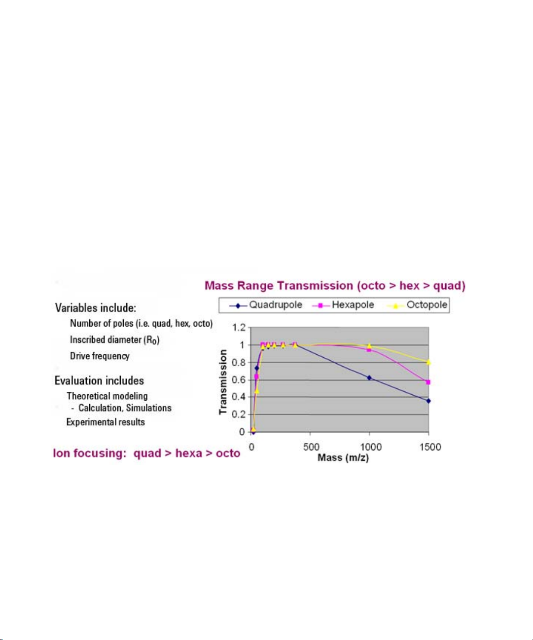
Why a hexapole?
The geometry of a hexapole provides advantages in two
domains: ion focusing and ion transmission (Figure 27).
• The first advantage is in ion focusing where a quadrupole is
better than a hexapole, which is better than an octopole, that
is, quadrupole > hexapole > octopole.
• The second advantage involves ion transmission across
a
wide mass range, or m/z bandwidth. In this case, the
octopole is better than the hexapole, which is better than the
quadrupole.
The hexapole is chosen because, overall, it is the best for both
ion focusing and ion transmission.
Figure 27 Broad mass range transmission and improved transmission efficiency using a hexapole
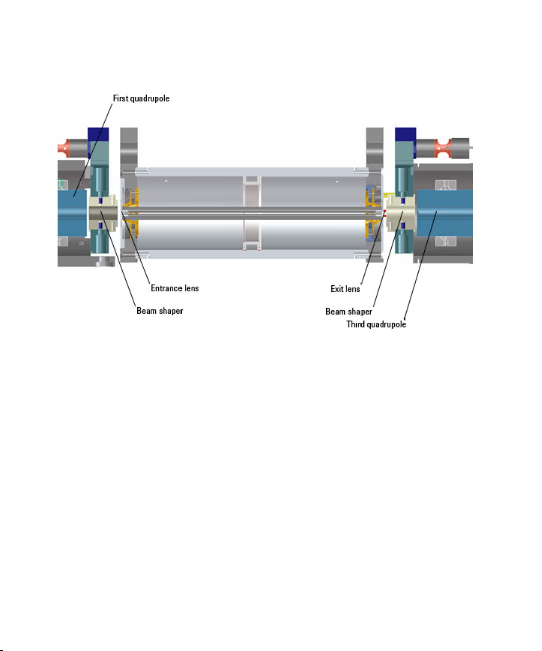
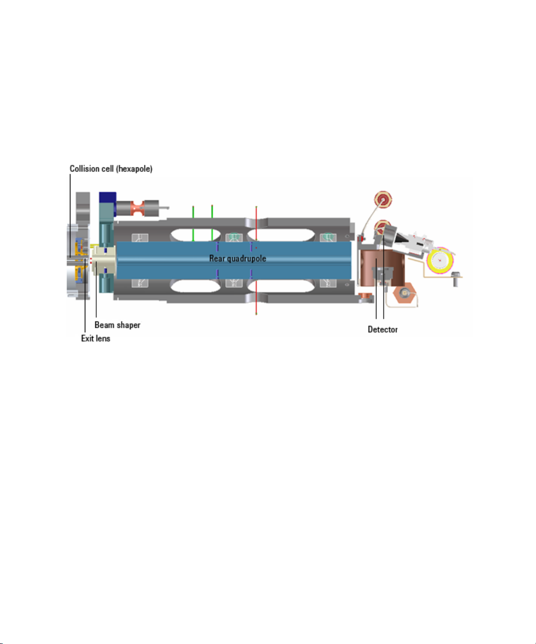
Collision cell design
The collision cell hexapole consists of six resistively coated rods
used to generate a potential difference across the length of the
collision cell (Figure 28).
Agilent 6400 Series Triple Quad LC/MS Concepts Guide 59
Page 60

3 Agilent Triple Quadrupole MS and Sensitivity
Collision cell
Figure 28 Collision cell design
A potential difference is always present. This ensures that the
precursor ions coming from MS1 (Q1), or fragment ions
generated in the collision cell, are transmitted and not allowed
to drift around at random.
Sweeping out the ions in this manner avoids the issue of
crosstalk where residual product ions from a previous MRM
experiment can interfere with the product ion spectrum of
a subsequent MRM experiment (see Figure 29). A collision
energy voltage is applied over the accelerating linear voltage to
generate fragments or product ions.
Length of time for collision cell flushing
The low degree of crosstalk can be demonstrated by examining
how long it takes to evacuate ions from the collision cell
(Figure 29).
60 Agilent 6400 Series Triple Quad LC/MS Concepts Guide
Page 61

Agilent Triple Quadrupole MS and Sensitivity 3
0 V Collision Energy
5 V Applied Axial Potential
Collision cell
Figure 29 Collision cell clearing profile (500 pg Alprazolam, 20 ms dwell
time)
The figure shows that the higher the mass the longer it takes to
evacuate the collision cell. For example, m/z 922 takes about
600 µsec to evacuate the collision cell using the linear potential,
while m/z 118 only takes 350 µsec. This also demonstrates the
low degree of crosstalk since the Y axis is logarithmic, showing
complete clearance of the cell. This means that an inter-scan
delay of 5 msec will be more than adequate to f lush the collision
cell of all ions.
Agilent 6400 Series Triple Quad LC/MS Concepts Guide 61
Page 62
3 Agilent Triple Quadrupole MS and Sensitivity
Detector
Detector
The High Energy Dynode detector assembly is unique to A gilent
(Figure 30).
Figure 30 Detector components
The two dynodes are orthogonal to the ion beam and neutrals.
This orientation reduces the possibility of neutral molecules
impacting the detector while at the same time attracting the
ions with high voltages. The dynodes serve to convert the ions
to electrons before they impact the multiplier. The off-axis
design also allows neutrals to pass through without hitting the
detector.
The multiplier has a long lifetime since only electrons are
allowed to impact it. Ions never impact its surface.
62 Agilent 6400 Series Triple Quad LC/MS Concepts Guide
Page 63
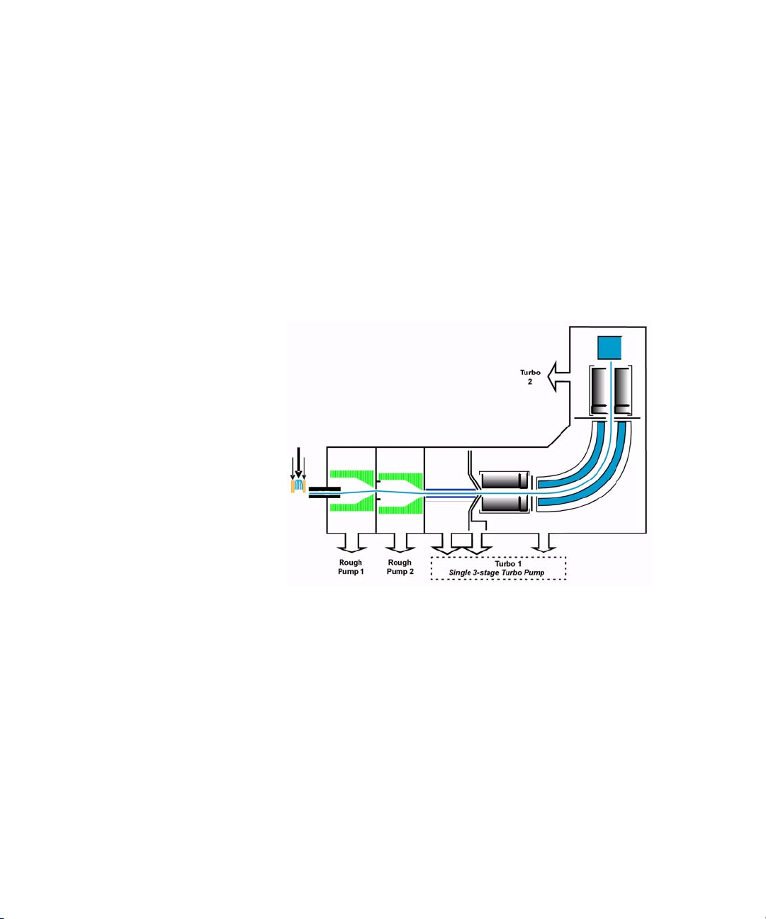
Pumping system
6490 Triple Quadrupole
The 6490 has two roughing pumps and a three-stage turbo pump
for the first five vacuum stages. The two roughing pumps are
needed to decrease the pressure in the Dual Ion Funnel. The
second turbo pump is added to the last vacuum stage to help
pump out the gas load coming from the hexapole field axial field
focusing curved collision cell.
Agilent Triple Quadrupole MS and Sensitivity 3
Pumping system
Figure 31 6490 Triple Quadrupole Pumping System
6460 and 6430 Triple Quadrupole
A single roughing pump and three-stage turbo pump are used
for the first four vacuum stages. This is achieved by partitioning
the turbo pump to create the multiple vacuum stages. The
second turbo pump is added to the fourth vacuum stage to help
pump out the gas load coming from the enhanced collision cell.
The turbo pumps are backed by a single roughing (mechanical)
pump (Figure 32).
Agilent 6400 Series Triple Quad LC/MS Concepts Guide 63
Page 64
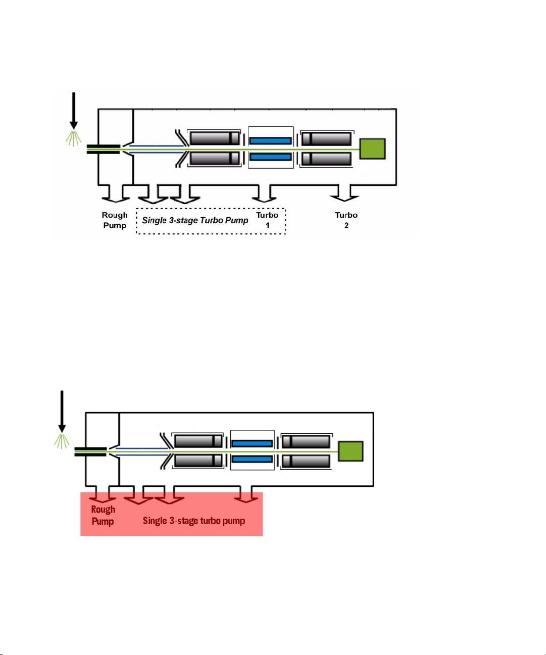
3 Agilent Triple Quadrupole MS and Sensitivity
Pumping system
Figure 32 6460 Triple Quadrupole pumping system
6410 or 6420 Triple Quadrupole
A single three-stage turbo pump is used for the entire vacuum
system. This is achieved by partitioning the turbo pump to
create the multiple vacuum stages. A second turbo pump is not
needed for the 6410 or for the 6420. This pump is backed by a
single roughing (mechanical) pump (Figure 33).
Figure 33 6410/6420 Triple Quadrupole pumping system
64 Agilent 6400 Series Triple Quad LC/MS Concepts Guide
Page 65

Agilent 6400 Series Triple Quadrupole LC/MS System
Concepts Guide
4
Agilent MassHunter Workstation
Software - Data Acquisition for 6400
Series Triple Quadrupole
Tuning 67
Acquisition 69
Learn the concepts to help you understand the design and
operation of the Agilent MassHunter Workstation Software LC/MS Data Acquisition for 6400 Series program.
The Data Acquisition program (Figure 34 on page 66) has the
following features:
• All LC and MS parameters are immediately visible.
• Real-time plots show the instrument at work.
• Running multiple samples is easily handled through
a
worklist—a spreadsheet-like interface.
Agilent Technologies
65
Page 66
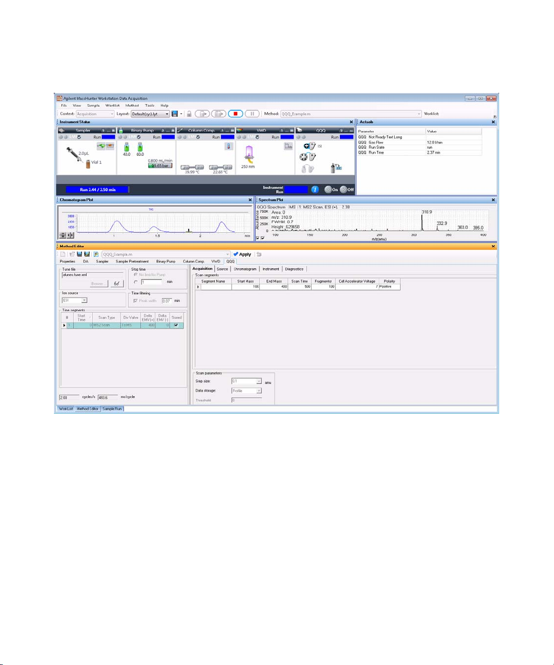
4 Agilent MassHunter Workstation Software - Data Acquisition for 6400 Series Triple Quadrupole
Figure 34 Data Acquisition program
With these windows you can do these operations:
• Control and monitor instrument settings
• Tune the instrument
• Set up acquisition parameters for the LC and the Triple
Quadrupole
• Monitor the chromatogram and mass spectra as samples are
analyzed
• Set up worklists for sequences of samples
66 Agilent 6400 Series Triple Quad LC/MS Concepts Guide
Page 67
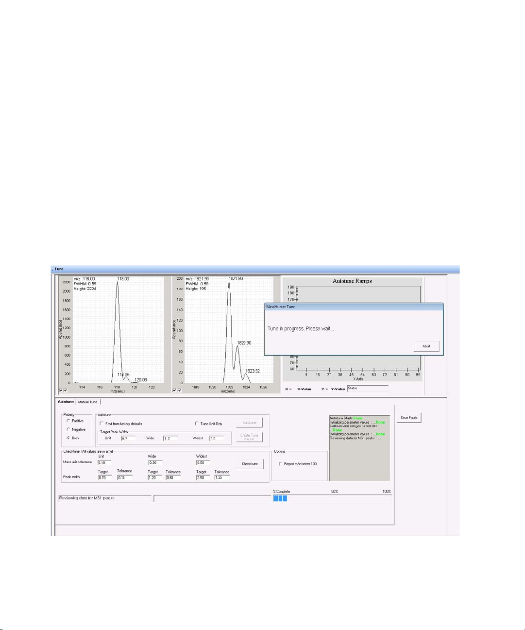
Agilent MassHunter Workstation Software - Data Acquisition for 6400 Series Triple Quadrupole 4
Tuning
Tuning
Autotune and Checktune
A Checktune can be used to determine if the tuning mix ion
masses are properly assigned and if the response or sensitivity
of these ions is within expectations. This check tune takes up to
15 minutes to run. An Autotune can be used if a more extensive
tune is recommended (Figure 35). For all models except the
6490, an Autotune can take 15 to 20 minutes for each polarity;
the 6490 takes approximately 45 minutes per ionization mode.
Everything is automatic since the tuning mix is delivered by the
calibrant delivery system (CDS), which is switched on
automatically during the tune.
Figure 35 Autotune in progress
Agilent 6400 Series Triple Quad LC/MS Concepts Guide 67
Page 68

4 Agilent MassHunter Workstation Software - Data Acquisition for 6400 Series Triple Quadrupole
Tuning
Manual Tune
A manual tune of user-defined ion masses with six
corresponding profile masses is available. An automated
version is also available for the Tuning Mix with Autotune.
You can adjust the EMV by clicking the Adjust EMV button on
the Detector tab.
You can Ramp many of the parameters by clicking the Ramp
button after selecting which parameter to ramp and entering
the range and step size.
You ca n a d just t h e Gain and Offset on the MS1 tab and on the
MS2 tab. You can also set acquisition parameters on the
Acquisition tab and then click the Acquire button to acquire a
data file.
Figure 36 The Detector tab in the Manual Tune tab
68 Agilent 6400 Series Triple Quad LC/MS Concepts Guide
Page 69

Agilent MassHunter Workstation Software - Data Acquisition for 6400 Series Triple Quadrupole 4
Acquisition
Acquisition
Many Agilent LC modules and the 6400 Series Triple
Quadrupole MS can be controlled and monitored (Instrument
Status window) from the same program used for entering
acquisition settings (Method Editor window) and setting up lists
of samples to run (Worklist window)(Figure 34 on page 66).
The Chromatogram Plot window also can show the MS and UV
chromatograms in real time.
Because of the large amount of information available, any of
these windows can be closed for easier viewing, if necessary.
However, one of the windows must always be open.
Figure 37 Instrument Status and real-time plot windows
Agilent 6400 Series Triple Quad LC/MS Concepts Guide 69
Page 70

4 Agilent MassHunter Workstation Software - Data Acquisition for 6400 Series Triple Quadrupole
Acquisition
70 Agilent 6400 Series Triple Quad LC/MS Concepts Guide
Page 71

Page 72

www.agilent.com
In This Book
The Concepts Guide
presents “The Big Picture”
behind the Agilent 6400
Series Triple Quadrupole
LC/MS to help you to
understand how the
hardware and software
work.
This guide includes
concepts for:
• Overview
• Inner Workings
• MS and Sensitivity
• Data Acquisition
program for 6400 Series
Triple Quadrupole
© Agilent Technologies, Inc. 2012
Revision A, November 2012
*G3335-90135*
G3335-90135
Agilent Technologies
 Loading...