

Page 1

Programmer’s Reference
Publication Number 54810-97076
March 2002
This reference applies directly to software revision code A.04.20 and later.
For Safety information, Warranties, and Regulatory information,
see the pages at the end of this book.
Copyright Agilent Technologies 1997-2002
All Rights Reserved.
Infiniium Oscilloscopes
Page 2
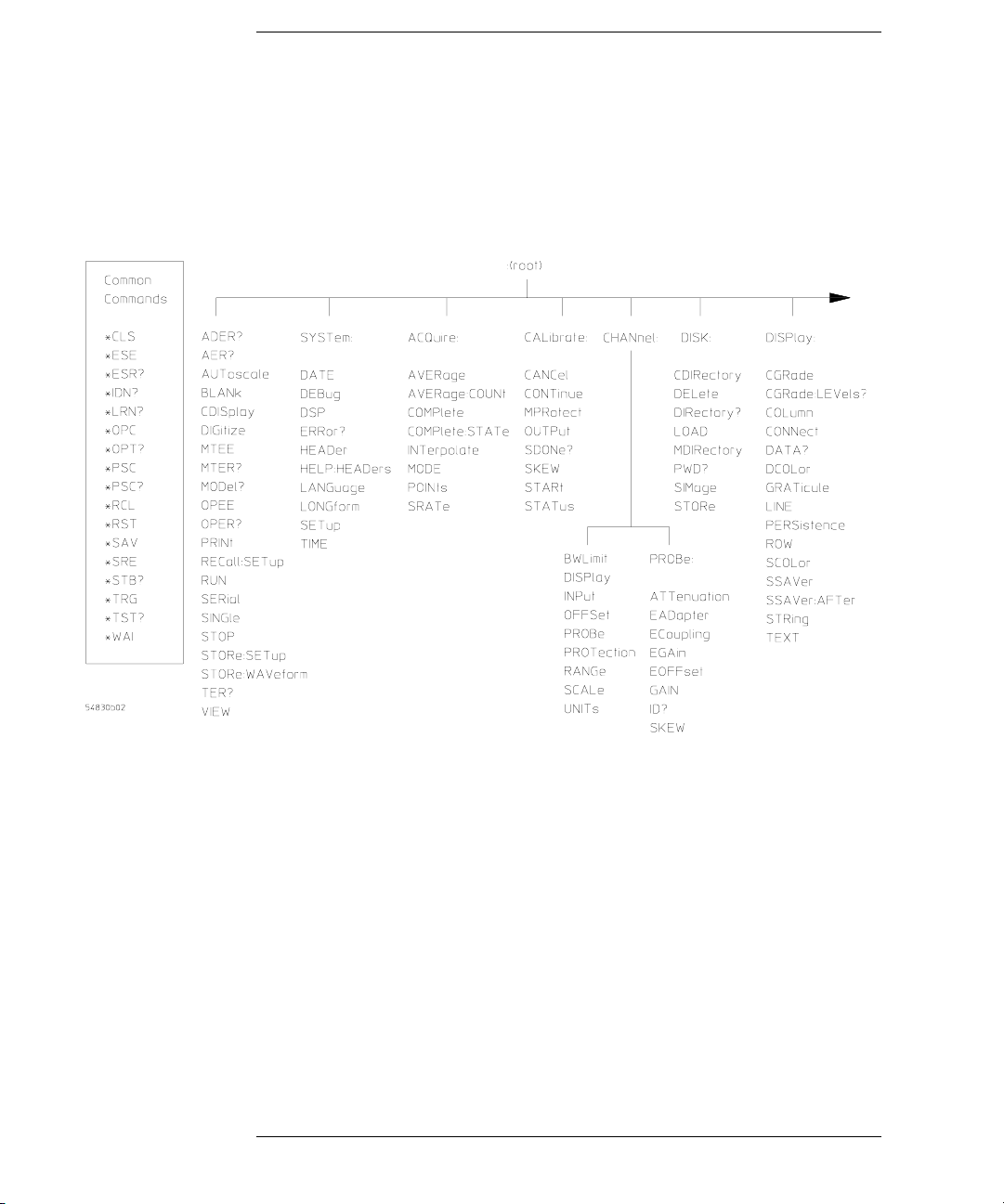
Programming Command Set
ii
Page 3
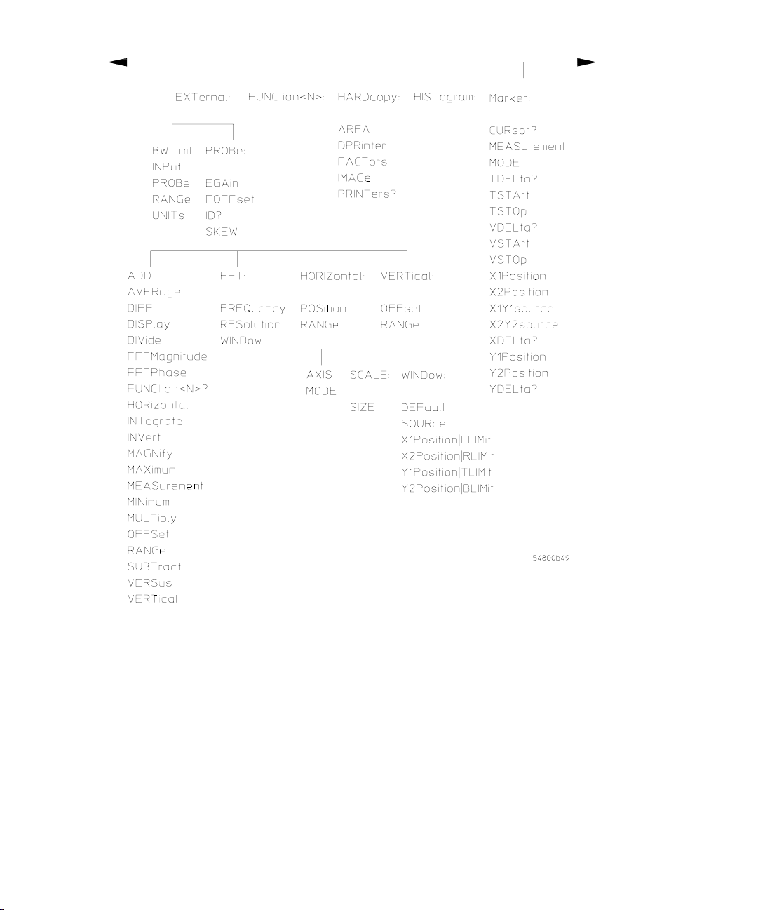
iiiivv
Page 4

Page 5
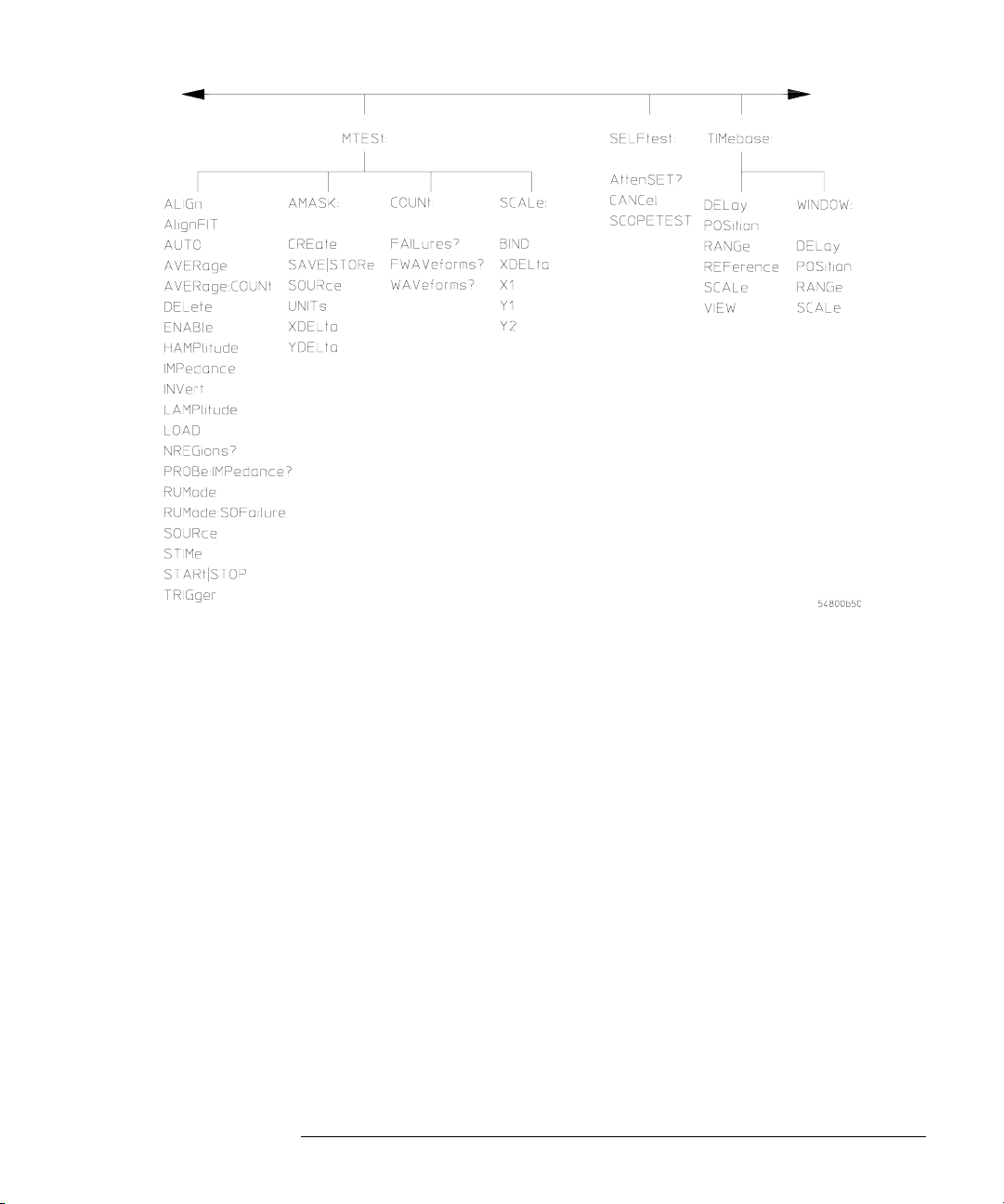
Page 6
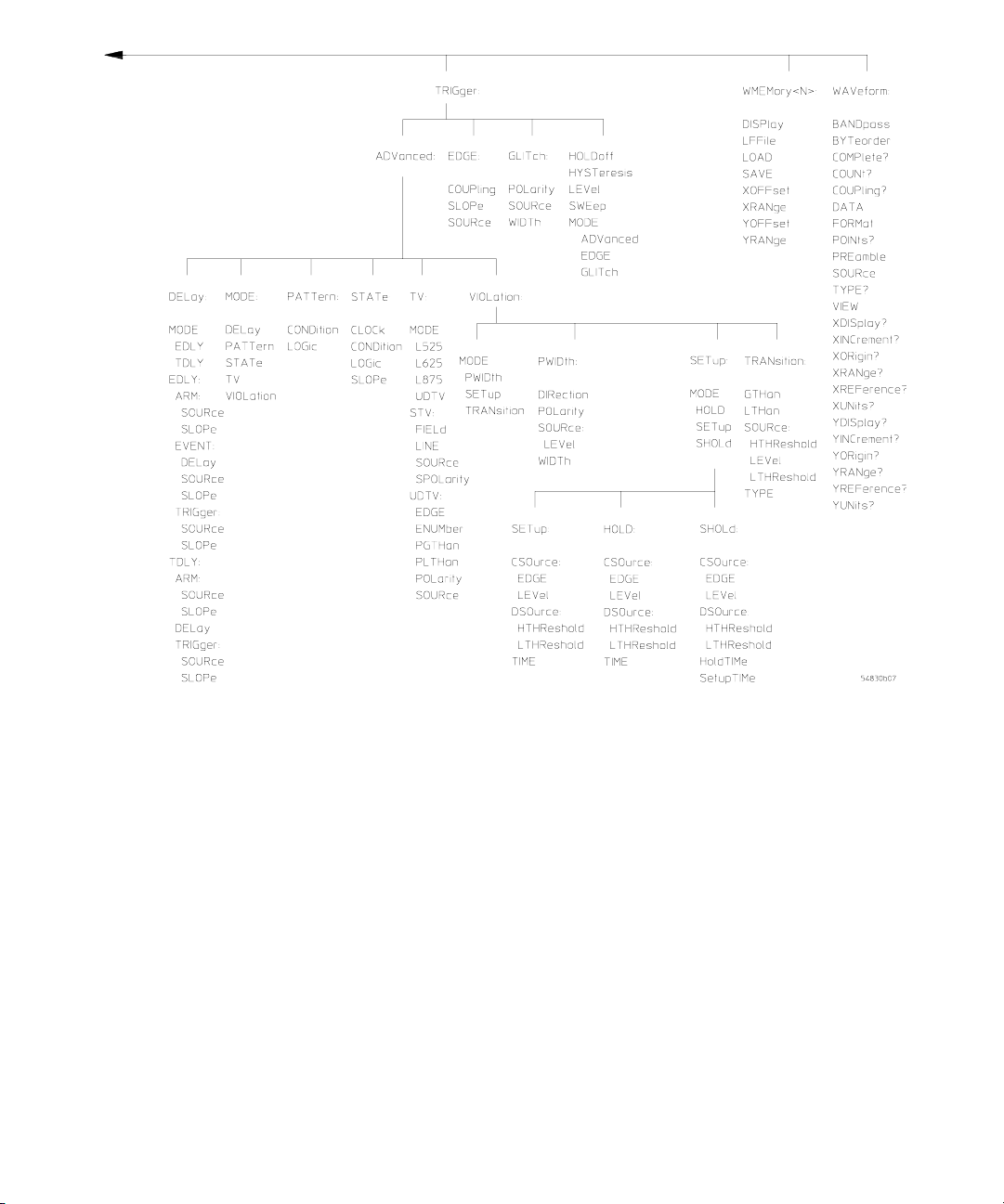
Page 7

In This Book
This book is your guide to programming the Infiniium-Series Oscilloscopes.
Chapters 1-5 give you an introduction to programming the oscilloscopes, along
with necessary conceptual information. These chapters describe basic program
communications, interface, syntax, data types, and status reporting.
Chapter 6 shows example BASIC and C programs, and describes chunks of one
program to show you some typical applications. The BASIC and C example
programs, and a "readme" file are also shipped on a disk with the oscilloscope.
Chapters 7-24 describe the commands used to program the Infiniium-Series
Oscilloscopes. Each chapter describes the set of commands that belong to an
individual subsystem, and explains the function of each command. These
chapters include:
Common HARDcopy
Root Level HISTogram
SYSTem MARKer
ACQuire MEASure
CALibration Mask TESt
CHANnel SELF-Test
DISK TIMe Base
DISPlay TRIGger
EXTernal Channel WAVeform
FUNCtion Waveform MEMory
Chapters 25 and 26 describe the language compatibility for 548xx,
Hewlett-Packard 547xx, and Hewlett-Packard 545xx Oscilloscopes. These
chapters also show you how to choose one of these command languages if you
want to use existing programs on Infiniium Oscilloscopes without having to
modify your programs.
Chapter 27 describes error messages.
Command syntax diagrams are in the Programmer’s Quick Reference.
A Quick Start Guide, Online User’s Guide, and Service Guide also ship with the
548xx oscilloscopes.
vii
Page 8

viii
Page 9

Contents
1 Introduction to Programming
Communicating with the Oscilloscope 1-3
Output Command 1-4
Device Address 1-4
Instructions 1-4
Instruction Header 1-4
White Space (Separator) 1-5
Braces 1-5
Ellipsis 1-5
Square Brackets 1-5
Program Data 1-5
Header Types 1-6
Duplicate Mnemonics 1-8
Query Headers 1-9
Program Header Options 1-10
Character Program Data 1-10
Numeric Program Data 1-11
Embedded Strings 1-12
Program Message Terminator 1-12
Common Commands within a Subsystem 1-13
Selecting Multiple Subsystems 1-13
Programming Getting Started 1-13
Initialization 1-14
Example Program using HP Basic 1-15
Using the DIGITIZE Command 1-16
Receiving Information from the Oscilloscope 1-18
String Variable Example 1-19
Numeric Variable Example 1-19
Definite-Length Block Response Data 1-20
Multiple Queries 1-21
Oscilloscope Status 1-21
2 LAN and GPIB Interfaces
LAN Interface Connector 2-3
GPIB Interface Connector 2-3
Default Startup Conditions 2-4
Interface Capabilities 2-5
GPIB Command and Data Concepts 2-6
Communicating Over the GPIB Interface 2-7
Communicating Over the LAN Interface 2-8
Bus Commands 2-9
Contents-1
Page 10

Contents
3 Message Communication and System Functions
Protocols 3-3
4 Status Reporting
Status Reporting Data Structures 4-5
Status Byte Register 4-8
Service Request Enable Register 4-10
Message Event Register 4-10
Trigger Event Register 4-10
Standard Event Status Register 4-11
Standard Event Status Enable Register 4-12
Operation Status Register 4-13
Operation Status Enable Register 4-14
Mask Test Event Register 4-15
Mask Test Event Enable Register 4-16
Trigger Armed Event Register 4-17
Error Queue 4-17
Output Queue 4-17
Message Queue 4-18
Clearing Registers and Queues 4-18
5 Programming Conventions
Data Flow 5-3
Truncation Rule 5-5
The Command Tree 5-6
Infinity Representation 5-13
Sequential and Overlapped Commands 5-13
Response Generation 5-13
EOI 5-13
6 Sample Programs
Sample Program Structure 6-3
Sample C Programs 6-4
Listings of the Sample Programs 6-20
gpibdecl.h Sample Header 6-21
srqagi.c Sample Program 6-23
learnstr.c Sample Program 6-25
sicl_IO.c Sample Program 6-29
natl_IO.c Sample Program 6-33
init.bas Sample Program 6-38
Contents-2
Page 11

srq.bas Sample Program 6-46
lrn_str.bas Sample Program 6-50
7 Common Commands
*CLS (Clear Status) 7-4
*ESE (Event Status Enable) 7-5
*ESR? (Event Status Register) 7-7
*IDN? (Identification Number) 7-9
*LRN? (Learn) 7-10
*OPC (Operation Complete) 7-12
*OPT? (Option) 7-13
*PSC (Power-on Status Clear) 7-14
*RCL (Recall) 7-15
*RST (Reset) 7-16
*SAV (Save) 7-17
*SRE (Service Request Enable) 7-18
*STB? (Status Byte) 7-20
*TRG (Trigger) 7-22
*TST? (Test) 7-23
*WAI (Wait) 7-24
Contents
8 Root Level Commands
AER? (Arm Event Register) 8-3
AUToscale 8-4
BLANk 8-5
CDISplay 8-6
DIGitize 8-7
MTEE 8-8
MTER? 8-9
MODel? 8-10
OPEE 8-11
OPER? 8-12
OVLEnable 8-13
OVLRegister? 8-14
PRINt 8-15
RECall:SETup 8-16
RUN 8-17
SERial (Serial Number) 8-18
SINGle 8-19
STOP 8-20
STORe:SETup 8-21
STORe:WAVeform 8-22
Contents-3
Page 12

Contents
TER? (Trigger Event Register) 8-23
VIEW 8-24
9 System Commands
DATE 9-3
DEBug 9-4
DSP 9-6
ERRor? 9-7
HEADer 9-8
HELP:HEADers 9-10
LANGuage 9-12
LONGform 9-13
SETup 9-15
TIME 9-17
10 Acquire Commands
AllowMaxSR 10-3
AVERage 10-4
AVERage:COUNt 10-5
BWLimit 10-6
COMPlete 10-7
COMPlete:STATe 10-9
CONFig 10-10
INTerpolate 10-11
MODE 10-12
POINts 10-13
POINts:AUTO 10-15
SRATe (Sample RATe) 10-16
SRATe:AUTO 10-18
11 Calibration Commands
Oscilloscope Calibration 11-3
Probe Calibration 11-4
Calibration Commands 11-5
CANCel 11-6
CONTinue 11-7
MPRotect 11-8
OUTPut 11-9
SDONe? 11-10
SKEW 11-11
STARt 11-12
Contents-4
Page 13

STATus? 11-13
12 Channel Commands
BWLimit 12-3
DISPlay 12-4
INPut 12-5
OFFSet 12-6
PROBe 12-7
PROBe:ATTenuation 12-9
PROBe:EADapter 12-10
PROBe:ECoupling 12-12
PROBe:EGAin 12-14
PROBe:EOFFset 12-15
PROBe:GAIN 12-16
PROBe:ID? 12-17
PROBe:SKEW 12-18
PROTection:CLEar 12-19
PROTection? 12-20
RANGe 12-21
SCALe 12-22
UNITs 12-23
Contents
13 Disk Commands
CDIRectory 13-3
DELete 13-4
DIRectory? 13-5
LOAD 13-6
MDIRectory 13-7
PWD? 13-8
SIMage 13-9
STORe 13-10
14 Display Commands
CGRade 14-3
CGRade:LEVels? 14-5
COLumn 14-7
CONNect 14-8
DATA? 14-9
DCOLor 14-10
GRATicule 14-11
LINE 14-13
PERSistence 14-14
Contents-5
Page 14

Contents
ROW 14-15
SCOLor 14-16
SSAVer 14-19
STRing 14-20
TEXT 14-21
15 External Channel Commands
BWLimit 15-3
INPut 15-4
PROBe 15-5
PROBe:ATTenuation 15-6
PROBe:EADapter 15-7
PROBe:ECoupling 15-9
PROBe:EGAin 15-11
PROBe:EOFFset 15-12
PROBe:GAIN 15-13
PROBe:ID? 15-14
PROBe:SKEW 15-15
RANGe 15-16
UNITs 15-17
16 Function Commands
FUNCtion<N>? 16-4
ADD 16-5
AVERage 16-6
DIFF (Differentiate) 16-7
DISPlay 16-8
DIVide 16-9
FFT:FREQuency 16-10
FFT:RESolution? 16-11
FFT:WINDow 16-12
FFTMagnitude 16-14
FFTPhase 16-15
HORizontal 16-16
HORizontal:POSition 16-17
HORizontal:RANGe 16-18
INTegrate 16-19
INVert 16-20
MAGNify 16-21
MAXimum 16-22
MEASurement 16-23
MINimum 16-25
Contents-6
Page 15

MULTiply 16-26
OFFSet 16-27
RANGe 16-28
SUBTract 16-29
VERSus 16-30
VERTical 16-31
VERTical:OFFSet 16-32
VERTical:RANGe 16-33
17 Hardcopy Commands
AREA 17-3
DPRinter 17-4
FACTors 17-6
IMAGe 17-7
PRINters? 17-8
18 Histogram Commands
AXIS 18-4
MODE 18-5
SCALe:SIZE 18-6
WINDow:DEFault 18-7
WINDow:SOURce 18-8
WINDow:X1Position | LLIMit 18-9
WINDow:X2Position | RLIMit 18-10
WINDow:Y1Position | BLIMit 18-11
WINDow:Y2Position | TLIMit 18-12
Contents
19 Marker Commands
CURSor? 19-3
MEASurement:READout 19-4
MODE 19-5
TDELta? 19-6
TSTArt 19-7
TSTOp 19-9
VDELta? 19-11
VSTArt 19-12
VSTOp 19-14
X1Position 19-16
X2Position 19-17
X1Y1source 19-18
X2Y2source 19-19
XDELta? 19-20
Contents-7
Page 16

Contents
Y1Position 19-21
Y2Position 19-22
YDELta? 19-23
20 Measure Commands
AREA 20-6
CGRade:CROSsing 20-7
CGRade:DCDistortion 20-8
CGRade:EHEight 20-9
CGRade:EWIDth 20-10
CGRade:JITTer 20-11
CGRade:QFACtor 20-12
CLEar 20-13
CTCJitter 20-14
DEFine 20-16
DELTatime 20-20
DUTYcycle 20-22
FALLtime 20-24
FFT:DFRequency 20-26
FFT:DMAGnitude 20-27
FFT:FREQuency 20-28
FFT:MAGNitude 20-29
FFT:PEAK1 20-30
FFT:PEAK2 20-31
FFT:THReshold 20-32
FREQuency 20-33
HISTogram:HITS 20-35
HISTogram:MEAN 20-37
HISTogram:MEDian 20-39
HISTogram:M1S 20-41
HISTogram:M2S 20-43
HISTogram:M3S 20-45
HISTogram:PEAK 20-47
HISTogram:PP 20-49
HISTogram:STDDev 20-51
JITTer:DIRection 20-53
JITTer:STATistics 20-55
NWIDth 20-57
OVERshoot 20-59
PERiod 20-61
PHASe 20-63
PREShoot 20-65
PWIDth 20-67
Contents-8
Page 17

RESults? 20-69
RISetime 20-72
SCRatch 20-74
SENDvalid 20-75
SOURce 20-76
STATistics 20-77
TEDGe 20-78
TMAX 20-80
TMIN 20-82
TVOLt 20-83
VAMPlitude 20-85
VAVerage 20-87
VBASe 20-89
VLOWer 20-91
VMAX 20-92
VMIDdle 20-94
VMIN 20-95
VPP 20-97
VRMS 20-99
VTIMe 20-101
VTOP 20-102
VUPPer 20-104
Contents
21 Mask Test Commands
ALIGn 21-4
AlignFIT 21-5
AMASk:CREate 21-7
AMASk:SOURce 21-8
AMASk:SAVE | STORe 21-9
AMASk:UNITs 21-10
AMASk:XDELta 21-11
AMASk:YDELta 21-13
AUTO 21-15
AVERage 21-16
AVERage:COUNt 21-17
COUNt:FAILures? 21-18
COUNt:FWAVeforms? 21-19
COUNt:WAVeforms? 21-20
DELete 21-21
ENABle 21-22
HAMPlitude 21-23
IMPedance 21-24
INVert 21-26
Contents-9
Page 18

Contents
LAMPlitude 21-27
LOAD 21-28
NREGions? 21-29
PROBe:IMPedance? 21-30
RUMode 21-31
RUMode:SOFailure 21-33
SCALe:BIND 21-34
SCALe:X1 21-35
SCALe:XDELta 21-36
SCALe:Y1 21-37
SCALe:Y2 21-38
SOURce 21-39
STARt | STOP 21-40
STIMe 21-41
TITLe? 21-42
TRIGger:SOURce 21-43
22 Self-Test Commands
AttenSET? 22-3
CANCel 22-4
SCOPETEST 22-5
23 Time Base Commands
DELay 23-3
POSition 23-5
RANGe 23-6
REFerence 23-7
SCALe 23-8
VIEW 23-9
WINDow:DELay 23-10
WINDow:POSition 23-12
WINDow:RANGe 23-13
WINDow:SCALe 23-14
24 Trigger Commands
Organization of Trigger Modes and Commands 24-5
Summary of Trigger Modes and Commands 24-6
Trigger Modes 24-8
HOLDoff 24-9
HTHReshold 24-10
HYSTeresis 24-11
Contents-10
Page 19

LEVel 24-12
LTHReshold 24-13
SWEep 24-14
Edge Trigger Mode and Commands 24-15
EDGE:COUPling 24-17
EDGE:SLOPe 24-18
EDGE:SOURce 24-19
Glitch Trigger Mode and Commands 24-20
GLITch:POLarity 24-22
GLITch:SOURce 24-23
GLITch:WIDTh 24-24
Advanced COMM Trigger Mode and Commands 24-25
COMM:BWIDth 24-26
COMM:ENCode 24-27
COMM:LEVel 24-28
COMM:PATTern 24-29
COMM:POLarity 24-30
COMM:SOURce 24-31
Contents
Advanced Pattern Trigger Mode and Commands 24-32
PATTern:CONDition 24-34
PATTern:LOGic 24-35
Advanced State Trigger Mode and Commands 24-36
STATe:CLOCk 24-38
STATe:CONDition 24-39
STATe:LOGic 24-40
STATe:LTYPe 24-41
STATe:SLOPe 24-42
Advanced Delay By Event Mode and Commands 24-43
EDLY:ARM:SOURce 24-45
EDLY:ARM:SLOPe 24-46
EDLY:EVENt:DELay 24-47
EDLY:EVENt:SOURce 24-48
EDLY:EVENt:SLOPe 24-49
EDLY:TRIGger:SOURce 24-50
EDLY:TRIGger:SLOPe 24-51
Contents-11
Page 20

Contents
Advanced Delay By Time Mode and Commands 24-52
TDLY:ARM:SOURce 24-54
TDLY:ARM:SLOPe 24-55
TDLY:DELay 24-56
TDLY:TRIGger:SOURce 24-57
TDLY:TRIGger:SLOPe 24-58
Advanced Standard TV Mode and Commands 24-59
STV:FIELd 24-61
STV:LINE 24-62
STV:SOURce 24-63
STV:SPOLarity 24-64
Advanced User Defined TV Mode and Commands 24-65
UDTV:EDGE 24-68
UDTV:ENUMber 24-69
UDTV:PGTHan 24-70
UDTV:PLTHan 24-71
UDTV:POLarity 24-72
UDTV:SOURce 24-73
Advanced Trigger Violation Modes 24-75
VIOLation:MODE 24-76
Pulse Width Violation Mode and Commands 24-77
VIOLation:PWIDth:SOURce 24-79
VIOLation:PWIDth:POLarity 24-80
VIOLation:PWIDth:DIRection 24-81
VIOLation:PWIDth:WIDTh 24-82
Setup Violation Mode and Commands 24-83
VIOLation:SETup:MODE 24-86
VIOLation:SETup:SETup:CSOurce 24-87
VIOLation:SETup:SETup:CSOurce:LEVel 24-88
VIOLation:SETup:SETup:CSOurce:EDGE 24-89
VIOLation:SETup:SETup:DSOurce 24-90
VIOLation:SETup:SETup:DSOurce:HTHReshold 24-91
VIOLation:SETup:SETup:DSOurce:LTHReshold 24-92
VIOLation:SETup:SETup:TIME 24-93
VIOLation:SETup:HOLD:CSOurce 24-94
VIOLation:SETup:HOLD:CSOurce:LEVel 24-95
VIOLation:SETup:HOLD:CSOurce:EDGE 24-96
Contents-12
Page 21

VIOLation:SETup:HOLD:DSOurce 24-97
VIOLation:SETup:HOLD:DSOurce:HTHReshold 24-98
VIOLation:SETup:HOLD:DSOurce:LTHReshold 24-99
VIOLation:SETup:HOLD:TIME 24-100
VIOLation:SETup:SHOLd:CSOurce 24-101
VIOLation:SETup:SHOLd:CSOurce:LEVel 24-102
VIOLation:SETup:SHOLd:CSOurce:EDGE 24-103
VIOLation:SETup:SHOLd:DSOurce 24-104
VIOLation:SETup:SHOLd:DSOurce:HTHReshold 24-105
VIOLation:SETup:SHOLd:DSOurce:LTHReshold 24-106
VIOLation:SETup:SHOLd:SetupTIMe (STIMe) 24-107
VIOLation:SETup:SHOLd:HoldTIMe (HTIMe) 24-108
Transition Violation Mode 24-109
VIOLation:TRANsition 24-111
VIOLation:TRANsition:SOURce 24-112
VIOLation:TRANsition:SOURce:HTHReshold 24-113
VIOLation:TRANsition:SOURce:LTHReshold 24-114
VIOLation:TRANsition:TYPE 24-115
Contents
25 Waveform Commands
BANDpass? 25-5
BYTeorder 25-6
CLIPped? 25-7
COMPlete? 25-8
COUNt? 25-9
COUPling? 25-10
DATA 25-11
FORMat 25-32
POINts? 25-35
PREamble 25-36
SOURce 25-41
TYPE? 25-42
VIEW 25-44
XDISplay? 25-46
XINCrement? 25-47
XORigin? 25-48
XRANge? 25-49
XREFerence? 25-50
XUNits? 25-51
YDISplay? 25-52
YINCrement? 25-53
YORigin? 25-54
Contents-13
Page 22

Contents
YRANge? 25-55
YREFerence? 25-56
YUNits? 25-57
26 Waveform Memory Commands
DISPlay 26-3
LOAD 26-4
SAVE 26-5
XOFFset 26-6
XRANge 26-7
YOFFset 26-8
YRANge 26-9
27 Infiniium and HP 547XX Digitizing Oscilloscopes Language
Compatibility
To select a command language 27-4
Acquisition System Command Language Compatibility 27-5
Calibration Command Language Compatibility 27-6
Channel Command Language Compatibility 27-7
Disk Command Language Compatibility 27-8
Display Command Language Compatibility 27-9
External Command Language Compatibility 27-10
FFT Command Language Compatibility 27-11
Function Command Language Compatibility 27-12
Hardcopy Command Language Compatibility 27-13
Limit Test Command Language Compatibility 27-14
Marker Command Language Compatibility 27-15
Measure Command Language Compatibility 27-16
Multiple Memory Command Language Compatibility 27-17
Memory Test Command Language Compatibility 27-18
Pixel Memory Command Language Compatibility 27-19
Self-Test Command Language Compatibility 27-20
Sequential Command Language Compatibility 27-21
System Command Language Compatibility 27-22
Time Base Command Language Compatibility 27-23
Trigger Command Language Compatibility 27-24
Waveform Command Language Compatibility 27-27
Waveform Memory Command Language Compatibility 27-28
Root Command Language Compatibility 27-29
Common Command Language Compatibility 27-30
Contents-14
Page 23

28 Infiniium and HP 545XX Oscilloscopes Language
Compatibility
To select a command language 28-4
Acquisition System Command Language Compatibility 28-5
Calibration Command Language Compatibility 28-6
Channel Command Language Compatibility 28-7
Disk Command Language Compatibility 28-8
Display Command Language Compatibility 28-9
External Command Language Compatibility 28-10
FFT Command Language Compatibility 28-11
Function Command Language Compatibility 28-12
Hardcopy Command Language Compatibility 28-13
Limit Test Command Language Compatibility 28-14
Marker Command Language Compatibility 28-15
Measure Command Language Compatibility 28-16
Multiple Memory Command Language Compatibility 28-18
Memory Test Command Language Compatibility 28-19
Pixel Memory Command Language Compatibility 28-20
Self-Test Command Language Compatibility 28-21
Sequential Command Language Compatibility 28-22
System Command Language Compatibility 28-23
Time Base Command Language Compatibility 28-24
Trigger Command Language Compatibility 28-25
Waveform Command Language Compatibility 28-28
Waveform Memory Command Language Compatibility 28-29
Root Command Language Compatibility 28-30
Common Command Language Compatibility 28-31
Contents
29 Error Messages
Error Queue 29-3
Error Numbers 29-4
Command Error 29-5
Execution Error 29-6
Device- or Oscilloscope-Specific Error 29-7
Query Error 29-8
List of Error Messages 29-9
Contents-15
Page 24

Contents-16
Page 25

1
Introduction to Programming
Page 26

Introduction to Programming
This chapter introduces the basics for remote programming of an
oscilloscope. The programming commands in this manual conform to
the IEEE 488.2 Standard Digital Interface for Programmable
Instrumentation. The programming commands provide the means of
remote control.
Basic operations that you can do with a computer and an oscilloscope
include:
• Set up the oscilloscope.
• Make measurements.
• Get data (waveform, measurements, and configuration) from the
oscilloscope.
• Send information, such as waveforms and configurations, to the
oscilloscope.
You can accomplish other tasks by combining these functions.
Example Programs are Written in HP BASIC and C
The programming examples for individual commands in this manual are written in
HP BASIC and C.
1-2
Page 27

Introduction to Programming
Communicating with the Oscilloscope
Communicating with the Oscilloscope
Computers communicate with the oscilloscope by sending and receiving
messages over a remote interface, such as a GPIB card or a Local Area Network
(LAN) card. Commands for programming normally appear as ASCII character
strings embedded inside the output statements of a “host” language available
on your computer. The input commands of the host language are used to read
responses from the oscilloscope.
For example, HP BASIC uses the OUTPUT statement for sending commands
and queries. After a query is sent, the response is usually read using the
HP BASIC ENTER statement. The ENTER statement passes the value across
the bus to the computer and places it in the designated variable.
For the GPIB interface, messages are placed on the bus using an output
command and passing the device address, program message, and a terminator.
Passing the device address ensures that the program message is sent to the
correct GPIB interface and GPIB device.
The following HP BASIC OUTPUT statement sends a command that sets the
channel 1 scale value to 500 mV:
OUTPUT <device address> ;":CHANNEL1:SCALE 500E3"<terminator>
The device address represents the address of the device being programmed.
Each of the other parts of the above statement are explained on the following
pages.
Use the Suffix Multiplier Instead
Using "mV" or "V" following the numeric voltage value in some commands will cause
Error 138 - Suffix not allowed. Instead, use the convention for the suffix multiplier as
described in chapter 3, "Message Communication and System Functions."
1-3
Page 28

Introduction to Programming
Output Command
Output Command
The output command depends entirely on the programming language.
Throughout this book, HP BASIC and ANSI C are used in the examples of
individual commands. If you are using other languages, you will need to find
the equivalents of HP BASIC commands like OUTPUT, ENTER, and CLEAR, to
convert the examples.
Device Address
The location where the device address must be specified depends on the
programming language you are using. In some languages, it may be specified
outside the OUTPUT command. In HP BASIC, it is always specified after the
keyword, OUTPUT. The examples in this manual assume that the oscilloscope
and interface card are at GPIB device address 707. When writing programs, the
device address varies according to how the bus is configured.
Instructions
Instructions, both commands and queries, normally appear as strings embedded
in a statement of your host language, such as BASIC, Pascal, or C. The only
time a parameter is not meant to be expressed as a string is when the
instruction's syntax definition specifies <block data>, such as HP BASIC’s
"learnstring" command. There are only a few instructions that use block data.
Instructions are composed of two main parts:
• The header, which specifies the command or query to be sent.
• The program data, which provides additional information to clarify the
meaning of the instruction.
Instruction Header
The instruction header is one or more command mnemonics separated by
colons (:). They represent the operation to be performed by the oscilloscope.
See the “Programming Conventions” chapter for more information.
Queries are formed by adding a question mark (?) to the end of the header.
Many instructions can be used as either commands or queries, depending on
whether or not you include the question ma rk. The command and query forms
of an instruction usually have different program data. Many queries do not use
any program data.
1-4
Page 29

Introduction to Programming
White Space (Separator)
White Space (Separator)
White space is used to separate the instruction header from the program data.
If the instruction does not require any program data parameters, you do not
need to include any white space. In this manual, white space is defined as one
or more spaces. ASCII defines a space to be character 32 in decimal.
Braces
Wh en se v e r al items are enclosed by braces, { }, only on e of these elements may
be selected. Vertical line ( | ) indicates "or". For example, {ON | OFF} indicates
that only ON or OFF may be selected, not both.
Ellipsis
... An ellipsis (trailing dots) indicates that the preceding element may be
repeated one or more times.
Square Brackets
Items enclosed in square brackets, [ ], are optional.
Program Data
Program data is used to clarify the meaning of the command or query. It
pr ov i d es necessary in f o r ma tion, such as wh e ther a function sh ou ld be on or off,
or which waveform is to be displayed. Each instruction’s syntax definition
shows the program data and the values they accept. See the Programmer’s
Quick Reference Guide for more information about general syntax rules and
acceptable values.
When there is more than one data parameter, they are separated by commas (,).
You can add spaces around the commas to improve readability.
1-5
Page 30

Introduction to Programming
Header Types
Header Types
There are three types of headers:
• Simple Command headers
• Compound Command headers
• Common Command headers
Simple Command Header
Simple command headers contain a single mnemonic. AUTOSCALE and
DIGITIZE are examples of simple command headers typically used in this
oscilloscope. The syntax is:
<program mnemonic><terminator>
or
OUTPUT 707;”:AUTOSCALE”
When program data must be included with the simple command header
(for example, :DIGITIZE CHAN1), white space is added to separate the data
from the header. The syntax is:
<program mnemonic><separator><program data><terminator>
or
OUTPUT 707;”:DIGITIZE CHANNEL1,FUNCTION2”
Compound Command Header
Compound command headers are a combination of two program mnemonics.
The first mnemonic selects the subsystem, and the second mnemonic selects
the function within that subsystem. The mnemonics within the compound
message are separated by colons. For example:
To execute a single function within a subsystem:
:<subsystem>:<function><separator><program data><terminator>
For example:
OUTPUT 707;”:CHANNEL1:BWLIMIT ON”
1-6
Page 31

Introduction to Programming
Header Types
Combining Commands in the Same Subsystem
To execute more than one command within the same subsystem, use a semicolon (;) to separate the commands:
:<subsystem>:<command><separator><data>;<command><separator>
<data><terminator>
For example:
:CHANNEL1:INPUT DC;BWLIMIT ON
Common Command Header
Common command headers, such as clear status, control the IEEE 488.2
functions within the oscilloscope. The syntax is:
*<command header><terminator>
No space or separator is allowed between the asterisk (*) and the command
header. *CLS is an example of a common command header.
1-7
Page 32

Introduction to Programming
Duplicate Mnemonics
Duplicate Mnemonics
Identical function mnemonics can be used for more than one subsystem. For
example, you can use the function mnemonic RANGE to change both the
vertical range and horizontal range:
To set the vertical range of channel 1 to 0.4 volts full scale:
:CHANNEL1:RANGE .4
To set the horizontal time base to 1 second full scale:
:TIMEBASE:RANGE 1
In these examples, CHANNEL1 and TIMEBASE are subsystem selectors, and
determine the range type being modified.
1-8
Page 33

Introduction to Programming
Query Headers
Query Headers
A command header immediately followed by a question mark (?) is a query.
After receiving a query, the oscilloscope interrogates the requested subsystem
and places the answer in its output queue. The answer remains in the output
queue until it is read or until another command is issued. When read, the answer
is transmitted across the bus to the designated listener (typically a computer).
For example, the query:
:TIMEBASE:RANGE?
places the current time base setting in the output queue.
In HP BASIC, the computer input statement:
ENTER < device address > ;Range
passes the value across the bus to the computer and places it in the variable
Range.
You can use queries to find out how the oscilloscope is currently configured and
to get results of measurements made by the oscilloscope.
For example, the command:
:MEASURE:RISETIME?
tells the oscilloscope to measure the rise time of your waveform and place the
result in the output queue.
The output queue must be read before the next program message is sent. For
example, when you send the query :MEASURE:RISETIME?, you must follow it
with an input statement. In HP BASIC, this is usually done with an ENTER
statement immediately followed by a variable name. This statement reads the
result of the query and places the result in a specified variable.
Handle Queries Properly
If you send an other command or que ry before reading the result of a q uery, the output
buffer is cleared and the current response is lost. This also generates a queryinterrupted error in the error queue. If you execute an input statement before you
send a query, it will cause the computer to wait indefinitely.
1-9
Page 34

Introduction to Programming
Program Header Options
Program Header Options
You can send program headers using any combination of uppercase or lowercase
ASCII characters. Oscilloscope responses, however, are always returned in
uppercase.
You may send program command and query headers in either long form
(complete spelling), short form (abbreviated spelling), or any combination of
long form and short form. For example:
:TIMEBASE:DELAY 1E-6 is the long form.
:TIM:DEL 1E-6 is the short form.
Using Long Form or Short Form
Programs written in long form are easily read and are almost self-documenting.
The short form syntax conserves the amount of computer memory needed for
program storage and reduces I/O activity.
The rules for the short form syntax are described in the chapter, “Programming
Conventions.”
Character Program Data
Character program data is used to convey parameter information as alpha or
alphanumeric strings. For example, the :TIMEBASE:REFERENCE command
can be set to left, center, or right. The character program data in this case may
be LEFT, CENTER, or RIGHT. The command :TIMEBASE:REFERENCE
RIGHT sets the time base reference to right.
The available mnemonics for character program data are always included with
the instruction's syntax definition. You may send either the long form of
commands, or the short form (if one exists). You may mix uppercase and
lowercase letters freely. When receiving responses, uppercase letters are used
exclusively.
1-10
Page 35

Introduction to Programming
Numeric Program Data
Numeric Program Data
Some command headers require program data to be expressed numerically. For
example, :TIMEBASE:RANGE requires the desired full-scale range to be
expressed numerically.
For numeric program data, you can use exponential notation or suffix
multipliers to indicate the numeric value. The following numbers are all equal:
28 = 0.28E2 = 280E-1 = 28000m = 0.028K = 28E-3K
When a syntax definition specifies that a number is an integer, it means that the
number should be whole. Any fractional part is ignored and truncated. Numeric
dat a p ar a me t ers t hat ac ce p t fr a ct i o na l v al u es ar e cal l ed re al nu m be r s. Fo r more
information see the chapter, “Interface Functions.”
All numbers are expected to be strings of ASCII characters.
• When sending the number 9, you would send a byte representing the
ASCII code for the character “9” (which is 57).
• A three-digit number like 102 would take up three bytes (ASCII codes 49,
48, and 50). The number of bytes is figured automatically when you
include the entire instruction in a string.
1-11
Page 36

Introduction to Programming
Embedded Strings
Embedded Strings
Embedded strings contain groups of alphanumeric characters which are treated
as a un i t of d at a b y th e osc i llo s co p e. A n exam p le of thi s i s th e lin e o f te x t wr i tt e n
to the advisory line of the oscilloscope with the :SYSTEM:DSP command:
:SYSTEM:DSP ""This is a message.""
You may delimit embedded strings with either single (’) or double (") quotation
marks. These strings are case-sensitive, and spaces are also legal characters.
Program Message Terminator
The pr ogr a m ins t ru c tio ns wi t hin a da ta me s sag e a re ex e cu t ed af t er th e p ro g ram
message terminator is received. The terminator may be either an NL (New
Line) character, an EOI (End-Or-Identify) asserted in the GPIB interface, or a
combination of the two. Asserting the EOI sets the EOI control line low on the
last byte of the data message. The NL character is an ASCII linefeed (decimal
10).
New Line Terminator Functions Like EOS and EOT
The NL (New Line) terminator has the same function as an EOS (End Of String) and
EOT (End Of Text) terminator.
1-12
Page 37

Introduction to Programming
Common Commands within a Subsystem
Common Commands within a Subsystem
Co m m o n co m m a n d s c a n be re c e iv ed a n d p r o c e s s ed b y th e os c i l l os co pe whe t h e r
they are sent over the bus as separate program messages or within other
program messages. If you have selec ted a sub system, and a common co mmand
is received by the oscilloscope, the oscilloscope remains in the selected
subsystem. For example, if the program message
":ACQUIRE:AVERAGE ON;*CLS;COUNT 1024"
is received by the oscilloscope, the oscilloscope turns averaging on, then clears
the status information without leaving the selected subsystem.
If some other type of command is received within a program message, you must
re-enter the original subsystem after the command. For example, the program
message
":ACQUIRE:AVERAGE ON;:AUTOSCALE;:ACQUIRE:AVERAGE:COUNT 1024"
turns averaging on, completes the autoscale operation, then sets the acquire
average count. Here, :ACQUIRE must be sent again after AUTOSCALE to reenter the ACQUIRE subsystem and set the count.
Selecting Multiple Subsystems
You can send multiple program commands and program queries for different
subsystems on the same line by separating each command with a semicolon.
The colon following the semicolon lets you enter a new subsystem. For example:
<program mnemonic><data>;:<program mnemonic><data><terminator>
:CHANNEL1:RANGE 0.4;:TIMEBASE:RANGE 1
You can Combine Compound and Simple Commands
Multiple program commands may be any combination of compound and simple
commands.
Programming Getting Started
The remainder of this chapter explains how to set up the oscilloscope, how to
retrieve setup information and measurement results, how to digitize a
waveform, and how to pass data to the computer. The chapter, “Measure
Commands” describes sending measurement data to the oscilloscope.
1-13
Page 38
Introduction to Programming
Initialization
Initialization
To make sure the bus and all appropriate interfaces are in a known state, begin
every program with an initialization statement. For example, HP BASIC
provides a CLEAR command which clears the interface buffer:
CLEAR 707 ! initializes the interface of the oscilloscope
When you are using GPIB, CLEAR also resets the oscilloscope’s parser. The
parser is the program that reads in the instructions you send.
After clearing the interface, initialize the oscilloscope to a preset state:
OUTPUT 707;"*RST" ! initializes the oscilloscope to a preset
state
Initializing the Oscilloscope
The commands and syntax for initializing the oscilloscope are discussed in the
chapter, “Common Commands.” Refer to your GPIB manual and programming
language reference manual for information on initializing the interface.
Autoscale
The AUTOSCALE feature of Agilent Technologies digitizing oscilloscopes
performs a very useful function on unknown waveforms by automatically setting
up the vertical channel, time base, and trigger level of the oscilloscope.
The syntax for the autoscale function is:
:AUTOSCALE<terminator>
Setting Up the Oscilloscope
A typical oscilloscope setup configures the vertical range and offset voltage, the
horizontal range, delay time, delay reference, trigger mode, trigger level, and
slope.
A typical example of the commands sent to the oscilloscope are:
:CHANNEL1:PROBE 10; RANGE 16;OFFSET 1.00<terminator>
:SYSTEM:HEADER OFF<terminator>
:TIMEBASE:RANGE 1E-3;DELAY 100E-6<terminator>
This example sets the time base at 1 ms full-scale (100 µs/div), with delay of
100 µs. Vertical is set to 16 V full-scale (2 V/div), with center of screen at 1 V,
and probe attenuation of 10.
1-14
Page 39

Introduction to Programming
Example Program using HP Basic
Example Program using HP Basic
This program demonstrates the basic command structure used to program the
oscilloscope.
10 CLEAR 707! Initialize oscilloscope interface
20 OUTPUT 707;"*RST"!Initialize oscilloscope to preset state
30 OUTPUT 707;":TIMEBASE:RANGE 5E-4"! Time base to 500 us full scale
40 OUTPUT 707;":TIMEBASE:DELAY 0"! Delay to zero
50 OUTPUT 707;":TIMEBASE:REFERENCE CENTER"! Display reference at center
60 OUTPUT 707;":CHANNEL1:PROBE 10"! Probe attenuation to 10:1
70 OUTPUT 707;":CHANNEL1:RANGE 1.6"! Vertical range to 1.6 V full scale
80 OUTPUT 707;":CHANNEL1:OFFSET -.4"! Offset to -0.4
90 OUTPUT 707;":CHANNEL1:INPUT DC"! Coupling to DC
100 OUTPUT 707;":TRIGGER:MODE EDGE"! Edge triggering
110 OUTPUT 707;":TRIGGER:LEVEL CHAN1,-.4"! Trigger level to -0.4
120 OUTPUT 707;":TRIGGER:SLOPE POSITIVE"! Trigger on positive slope
125 OUTPUT 707;":SYSTEM:HEADER OFF<terminator>
130 OUTPUT 707;":ACQUIRE:MODE RTIME"! Normal acquisition
140 OUTPUT 707;":DISPLAY:GRATICULE FRAME"! Grid off
150 END
Overview of the Program
• Line 10 initializes the oscilloscope interface to a known state.
• Line 20 initializes the oscilloscope to a preset state.
• Lines 30 through 50 set the time base, the horizontal time at 500 µs full scale,
and 0 s of delay referenced at the center of the graticule.
• Lines 60 through 90 set 10:1 probe attenuation, set the vertical range to
1.6 volts full scale, center screen at −0.4 volts, and select DC 1 Mohm
impedance coupling.
• Lines 100 through 120 configure the oscilloscope to trigger at −0.4 volts with
positive edge triggering.
• Line 125 turns system headers off.
• Line 130 configures the oscilloscope for real time acquisition.
• Line 140 turns the grid off.
1-15
Page 40

Introduction to Programming
Using the DIGITIZE Command
Using the DIGITIZE Command
The DIGITIZE command is a macro that captures data using the acquisition
(ACQUIRE) subsystem. When the digitize proces s is complete, the acquisition
is stopped. You can measure the captured data by using the oscilloscope or by
transferring the data to a computer for further analysis. The captured data
consists of two parts: the preamble and the waveform data record.
A f t e r c h a n g i n g th e o s c i l l o s c o p e c o n f i g u r a t i o n , t h e w a v e f o r m b u f f e r s a r e c l e a r e d .
Before doing a measurement, you should send the DIGITIZE command to
ensure new data has been collected.
You can send the DIGITIZE command with no parameters for a higher
throughput. Refer to the DIGITIZE command in the chapter, “Root Level
Commands” for details.
When the DI GITIZE co mmand is se nt to an os c illosco p e , the sp e c i fied ch a n nel’s
waveform is digitized using the current ACQUIRE parameters. Before sending
the :WAVEFORM:DATA? query to download waveform data to your computer,
you should specify the WAVEFORM parameters.
The number of data points comprising a waveform varies according to the
number requested in the ACQUIRE subsystem. The ACQUIRE subsystem
determines the number of data points, type of acquisition, and number of
averages used by the DIGITIZE command. This lets you specify exactly what
the digitized information contains. The following program example shows a
typical setup:
OUTPUT 707;":SYSTEM:HEADER OFF<terminator>
OUTPUT 707;":ACQUIRE:MODE RTIME"<terminator>
OUTPUT 707;":ACQUIRE:COMPLETE 100"<terminator>
OUTPUT 707;":WAVEFORM:SOURCE CHANNEL1"<terminator>
OUTPUT 707;":WAVEFORM:FORMAT BYTE"<terminator>
OUTPUT 707;":ACQUIRE:COUNT 8"<terminator>
OUTPUT 707;":ACQUIRE:POINTS 500"<terminator>
OUTPUT 707;":DIGITIZE CHANNEL1"<terminator>
OUTPUT 707;":WAVEFORM:DATA?"<terminator>
This setup places the oscilloscope into the real time sampling mode using eight
averages. This means that when the DIGITIZE command is received, the
command will execute until the waveform has been averaged at least eight
times.
After receiving the :WAVEFORM:DATA? query, the oscilloscope will start
downloading the waveform information.
Digitized waveforms are passed from the oscilloscope to the computer by
sending a numerical representation of each digitized point. The format of the
numerical representation is controlled by using the :WAVEFORM:FORMAT
command and may be selected as BYTE, WORD, or ASCII.
1-16
Page 41

Introduction to Programming
Using the DIGITIZE Command
The easiest method of receiving a digitized waveform depends on data
structures, available formatting, and I/O capabilities. You must convert the data
values to determine the voltage value of each point. These data values are
passed starting with the left most point on the oscilloscope’s display. For more
information, refer to the chapter, “Waveform Commands.”
When using GPIB, you may abort a digitize operation by sending a Device Clear
over the bus (for example, CLEAR 707).
1-17
Page 42

Introduction to Programming
Receiving Information from the Oscilloscope
Receiving Information from the Oscilloscope
After receiving a query (a command header followed by a question mark), the
oscilloscope places the answer in its output queue. The answer remains in the
output queue until it is read or until another command is issued. When read,
the answer is transmitted across the interface to the computer. The input
statement for receiving a response message from an oscilloscope’s output queue
typically has two parameters; the device address and a format specification for
handling the response message. For example, to read the result of the query
command :CHANNEL1:INPUT? you would execute the HP BASIC statement:
ENTER <device address> ;Setting$
This would enter the current setting for the channel 1 coupling in the string
variable Setting$. The device address parameter represents the address of the
oscilloscope.
All results for queries sent in a program message must be read before another
program message is sent. For example, when you send the query
:MEASURE:RISETIME?, you must follow that query with an input statement.
In HP BASIC, this is usually done with an ENTER statement.
Handle Queries Properly
If you send another command or query before reading the result of a query, the output
buffer will be cleared and the current response will be lost. This will also generate
a query-interrupted error in the error queue. If you execute an input statement before
you send a query, it will cause the computer to wait indefinitely.
The format specification for handling response messages depends on both the
computer and the programming language.
1-18
Page 43

Introduction to Programming
String Variable Example
String Variable Example
The output of the oscilloscope may be numeric or character data depending on
what is queried. Refer to the specific commands for the formats and types of
data returned from queries.
For the example programs, assume that the device being programmed is at
device address 707. The actual address depends on how you have configured
the bus for your own application.
In HP BASIC 5.0, string variables are case-sensitive, and must be expressed
exactly the same each time they are used. This example shows the data being
returned to a string variable:
10 DIM Rang$[30]
20 OUTPUT 707;":CHANNEL1:RANGE?"
30 ENTER 707;Rang$
40 PRINT Rang$
50 END
After running this program, the computer displays:
+8.00000E-01
Numeric Variable Example
This example shows the data being returned to a numeric variable:
10 OUTPUT 707;":CHANNEL1:RANGE?"
20 ENTER 707;Rang
30 PRINT Rang
40 END
After running this program, the computer displays:
.8
1-19
Page 44

Introduction to Programming
Definite-Length Block Response Data
Definite-Length Block Response Data
Definite-length block response data allows any type of device-dependent data
to be tr an s mi t ted over th e sys te m int e rfa c e as a s eri es of 8-bi t b in a ry da ta by tes .
This is particularly useful for sending large quantities of data or 8-bit extended
ASCII codes. The syntax is a pound sign ( # ) followed by a non-zero digit
representing the number of digits in the decimal integer. After the non-zero
digit is the decimal integer that states the number of 8-bit data bytes being sent.
This is followed by the actual data.
For example, for transmitting 4000 bytes of data, the syntax would be:
#44000 <4000 bytes of data> <terminator>
The lifetimes “4” represents the number of digits in the number of bytes, and
“4000” represents the number of bytes to be transmitted.
1-20
Page 45

Introduction to Programming
Multiple Queries
Multiple Queries
You can send multiple queries to the oscilloscope within a single program
message, but you must also read them back within a single program message.
This can be accomplished by either reading them back into a string variable or
into multiple numeric variables. For example, you could read the result of the
query :TIMEBASE:RANGE?;DELAY? into the string variable Results$ with the
command:
ENTER 707;Results$
When you read the result of multiple queries into string variables, each response
is separated by a semicolon. For example, the response of the query
:TIMEBASE:RANGE?;DELAY? would be:
<range_value>;<delay_value>
Use the following program message to read the query
:TIMEBASE:RANGE?;DELAY? into multiple numeric variables:
ENTER 707;Result1,Result2
Oscilloscope Status
Status registers track the current status of the oscilloscope. By checking the
oscilloscope status, you can find out whether an operation has completed and
is receiving triggers. The chapter, “Status Reporting” explains how to check
the status of the oscilloscope.
1-21
Page 46

1-22
Page 47

2
LAN and GPIB Interfaces
Page 48

LAN and GPIB Interfaces
There are two types of interfaces that can be used to remotely program
the Infiniium oscilloscope: Local Area Network (LAN) interface and
GPIB interface.
2-2
Page 49

LAN Interface Connector
The oscilloscope is equiped with a LAN interface RJ-45 connector on the
rear panel. This allows direct connect to your network. However, before
you can use the LAN interface to program the oscilloscope, the network
properties must be configured. Unless you are a Network Administrator,
you should contact your Network Administrator to add the appropriate
client, protocols, and configuration information for your LAN. This
information is different for every company.
GPIB Interface Connector
The oscilloscope is equipped with a GPIB interface connector on the rear panel.
This allows direct connection to a GPIB equipped computer. You can connect
an external GPIB compatible device to the oscilloscope by installing a GPIB
cable between the two units. Finger tighten the captive screws on both ends
of the GPIB cable to avoid accidentally disconnecting the cable during
operation.
A maximum of fifteen GPIB compatible instruments (including a computer) can
be interconnected in a system by stacking connectors. This allows the
oscilloscopes to be connected in virtually any configuration, as long as there is
a path from the computer to every device operating on the bus.
CAUTION Avoid stacking more than three or four cables on any one connector. Multiple
connectors produce leverage that can damage a connector mounting.
2-3
Page 50

LAN and GPIB Interfaces
Default Startup Conditions
Default Startup Conditions
The following default conditions are established during power-up:
• The Request Service (RQS) bit in the status byte register is set to zero.
• All of the event registers are cleared.
• The Standard Event Status Enable Register is set to 0xFF hex.
• Service Request Enable Register is set to 0x80 hex.
• The Operation Status Enable Register is set to 0xFFFF hex.
• The Overload Event Enable Register is set to 0xFF hex.
• The Mask Test Event Enable Register is set to 0xFF hex.
You can change the default conditions using the *PSC command with a
par a me t e r of 1 ( on e ). Wh e n se t to 1, th e Stan dar d Eve n t Sta t us En abl e Reg i st e r
is set 0x00 he x and the Se r vice Re q u est Enab l e Register is set to 0x00 he x . This
prevents the Power On (PON) event from setting the SRQ interrupt when the
oscilloscope is ready to receive commands.
2-4
Page 51

Interface Capabilities
The interface capabilities of this oscilloscope, as defined by IEEE 488.1 and
IEEE 488.2, are listed in Table 2-1.
Table 2-1 Interface Capabilities
Code Interface Function Capability
SH1 Source Handshake Full Capability
AH1 Acceptor Handshake Full Capability
T5 Talker Basic Talker/Serial Poll/Talk Only Mode/
L4 Listener Basic Listener/
SR1 Service Request Full Capability
RL1 Remote Local Complete Capability
PP0 Parallel Poll No Capability
DC1 Device Clear Full Capability
DT1 Device Trigger Full Capability
C0 Computer No Capability
E2 Driver Electronics Tri State (1 MB/SEC MAX)
LAN and GPIB Interfaces
Interface Capabilities
Unaddress if Listen Address (MLA)
Unaddresses if Talk Address (MTA)
2-5
Page 52

LAN and GPIB Interfaces
GPIB Command and Data Concepts
GPIB Command and Data Concepts
Th e GP I B in t e r f a c e ha s t w o m o d e s of o p e r a t i o n : c om m an d m od e an d d a t a m od e .
The interface is in the command mode when the Attention (ATN) control line
is true. The command mode is used to send talk and listen addresses and various
interface commands such as group execute trigger (GET).
The interface is in the data mode when the ATN line is false. The data mode is
used to convey device-dependent messages across the bus. The
device-dependent messages include all of the oscilloscope-specific commands,
queries, and responses found in this manual, including oscilloscope status
information.
2-6
Page 53
LAN and GPIB Interfaces
Communicating Over the GPIB Interface
Communicating Over the GPIB Interface
Device addresses are sent by the computer in the command mode to specify
who ta l ks and who listens. Becaus e GP IB can address multiple de v i c es through
the same interface card, the device address passed with the program message
must include the correct interface select code and the correct oscilloscope
address.
Device Address = (Interface Select Code * 100) + Oscilloscope Address
The Oscilloscope is at Address 707 for Programming Examples
The programming examples in this manual assume that the oscilloscope is at device
address 707.
Interface Select Code
Each interface card has a unique interface select code. This code is used by
the computer to direct commands and communications to the proper interface.
The default is typically “7” for the GPIB interface cards.
Oscilloscope Address
Each oscilloscope on the GPIB must have a unique oscilloscope address
between decimal 0 and 30. This oscilloscope address is used by the computer
to direct commands and communications to the proper oscilloscope on an
interface. The default is typically “7” for this oscilloscope. You can change the
oscilloscope address in the Utilities, Remote Interface dialog box.
Do Not Use Address 21 for an Oscilloscope Address
Address 21 is usually reserved for the Computer interface Talk/Listen address, and
should not be used as an oscilloscope address.
2-7
Page 54
Communicating Over the LAN Interface
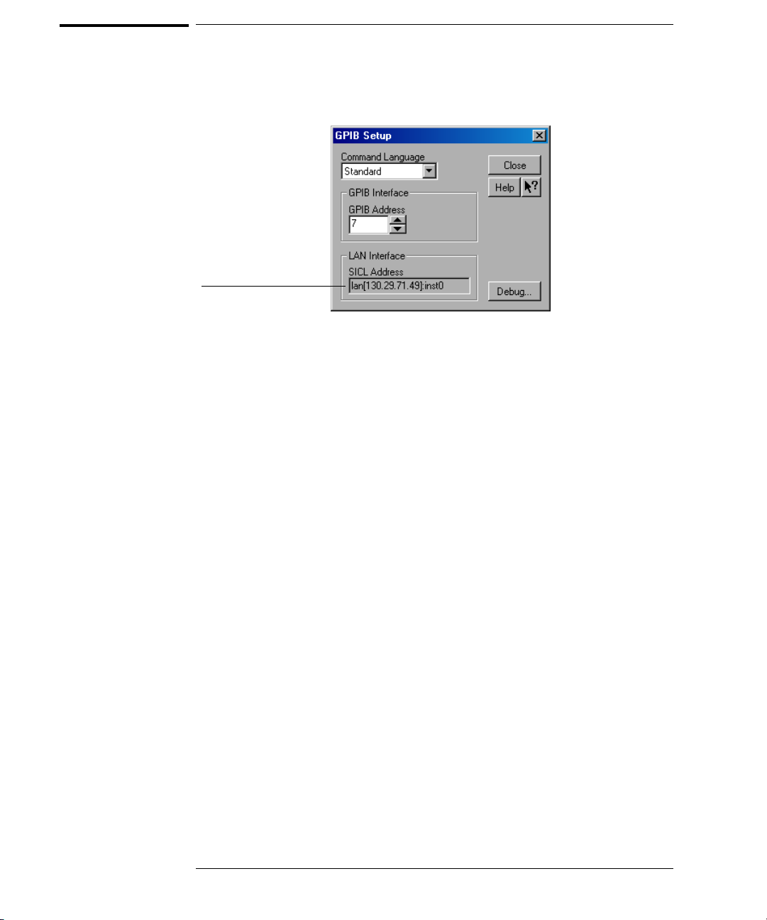
The device address used to send commands and receive data using the LAN
interface is located in the GPIB Setup dialog box as shown below.
LAN Address
GPIB Setup Dialog Box
The following C example program shows how to communicate with the
oscilloscope using the LAN interface and the Agilent Standard Instrument
Control Library (SICL).
#include <sicl.h>
#define BUFFER_SIZE 100
main()
{
INST Bus;
int reason;
unsigned long actualcnt;
char buffer[ BUFFER_SIZE ];
/* Open the LAN interface */
Bus = iopen( “lan[130.29.71.49]:inst0” );
if( Bus != 0 ) {
/* Bus timeout set to 20 seconds */
itimeout( Bus, 20000 );
/* Clear the interface */
iclear( Bus );
/* Query and print the oscilloscope’s Id */
iwrite( Bus, “*IDN?”, 5, 1, &actualcnt );
iread( Bus, buffer, BUFFER_SIZE, &reason, &actualcnt );
buffer[ actualcnt - 1 ] = 0;
printf( “%s\n”, buffer );
iclose( Bus );
}
}
2-8
Page 55

LAN and GPIB Interfaces
Bus Commands
Bus Commands
The following commands are IEEE 488.1 bus commands (ATN true).
IEEE 488.2 defines many of the actions that are taken when these commands
are received by the oscilloscope.
Device Clear
The device clear (DCL) and selected device clear (SDC) commands clear the
input buffer and output queue, reset the parser, and clear any pending
commands. If either of these commands is sent during a digitize operation, the
digitize operation is aborted.
Group Execute Trigger
The group execute trigger (GET) command arms the trigger. This is the same
action produced by sending the RUN command.
Interface Clear
The interface clear (IFC) command halts all bus activity. This includes
unaddressing all listeners and the talker, disabling serial poll on all devices, and
returning control to the system computer.
2-9
Page 56

2-10
Page 57

3
Message Communication and System
Functions
Page 58

Message Communication and System Functions
This chapter describes the operation of oscilloscopes that operate in
compliance with the IEEE 488.2 (syntax) standard. It is intended to give
you enough basic information about the IEEE 488.2 standard to
successfully program the oscilloscope. You can find additional detailed
information about the IEEE 488.2 standard in ANSI/IEEE Std 488.21987, “IEEE Standard Codes, Formats, Protocols, and Common
Commands.”
This oscilloscope series is designed to be compatible with other Agilent
Technologies IEEE 488.2 compatible instruments. Oscilloscopes that
are compatible with IEEE 488.2 must also be compatible with IEEE 488.1
(GPIB bus standard); however, IEEE 488.1 compatible oscilloscopes
may or may not conform to the IEEE 488.2 standard. The IEEE 488.2
standard defines the message exchange protocols by which the
oscilloscope and the computer will communicate. It also defines some
common capabilities that are found in all IEEE 488.2 oscilloscopes.
This chapter also contains some information about the message
communication and system functions not specifically defined by
IEEE 488.2.
3-2
Page 59

Message Communication and System Functions
Protocols
Protocols
The message exchange protocols of IEEE 488.2 define the overall scheme used
by the computer and the oscilloscope to communicate. This includes defining
when it is appropriate for devices to talk or listen, and what happens when the
protocol is not followed.
Functional Elements
Before proceeding with the description of the protocol, you should understand
a few system components, as described here.
Input Buffer The input buffer of the oscilloscope is the
memory area where commands and queries are
stored prior to being parsed and executed. It
all o ws a co mpu ter to sen d a str i ng of c om m an d s,
which could take some time to execute, to the
oscilloscope, then proceed to talk to another
oscilloscope while the first oscilloscope is
parsing and executing commands.
Output Queue The output queue of the oscilloscope is the
memory area where all output data or response
messages are stored until read by the computer.
Parser The oscilloscope’s parser is the component
that interprets the commands sent to the
oscilloscope and decides what actions should be
taken. “Parsing” refers to the action taken by
the parser to achieve this goal. Parsing and
execution of commands begins when either the
oscilloscope recognizes a program message
terminator, or the input buffer becomes full. If
you want to send a long sequence of commands
to be executed, then talk to another oscilloscope
while they are executing, you should send all of
the commands before sending the program
message terminator.
3-3
Page 60

Message Communication and System Functions
Protocols
Protocol Overview
The oscilloscope and computer communicate using program messages and
response messages. These messages serve as the containers into which sets of
program commands or oscilloscope responses are placed.
A program message is sent by the computer to the oscilloscope, and a response
message is sent from the oscilloscope to the computer in response to a query
message. A query message is defined as being a program message that contains
on e or mo r e qu eries. The oscilloscope wil l on ly talk when it has receive d a vali d
query message, and therefore has something to say. The computer should only
attempt to read a respo nse after sen ding a comple te quer y message, but before
sending another program message.
Remember this Rule of Oscilloscope Communication
The basic rule to remember is that the oscilloscope will only talk when prompted to,
and it then expects to talk before being told to do something else.
Protocol Operation
When you turn the oscilloscope on, the input buffer and output queue are
cleared, and the parser is reset to the root level of the command tree.
The oscilloscope and the computer communicate by exchanging complete
program messages and response messages. This means that the computer
should always terminate a program message before attempting to read a
response. The oscilloscope will terminate response messages except during a
hard copy output.
After you send a query message, the next message should be the response
message. The computer should always read the complete response message
associated with a query message before sending another program message to
the same oscilloscope.
The oscilloscope allows the computer to send multiple queries in one query
message. This is called sending a “compound query.” Multiple queries in a query
message are separated by semicolons. The responses to each of the queries in
a compound query will also be separated by semicolons.
Commands are executed in the order they are received.
Protocol Exceptions
If an error occurs during the information exchange, the exchange may not be
completed in a normal manner.
3-4
Page 61

Message Communication and System Functions
Protocols
Suffix Multiplier
The suffix multipliers that the oscilloscope will accept are shown in Table 3-1.
Table 3-1
Table 3-2
<suffix mult>
Value Mnemonic Value Mnemonic
1E18 EX 1E-3 M
1E15 PE 1E-6 U
1E12 T 1E-9 N
1E9 G 1E-12 P
1E6 MA 1E-15 F
1E3 K 1E-18 A
Suffix Unit
The suffix units that the oscilloscope will accept are shown in Table 3-2.
<suffix unit>
Suffix Referenced Unit
VVolt
S Second
3-5
Page 62

3-6
Page 63

4
Status Reporting
Page 64

Status Reporting
An overview of the oscilloscope’s status reporting structure is shown in
Figure 4-1. The status reporting structure shows you how to monitor
specific events in the oscilloscope. Monitoring these events lets you
determine the status of an operation, the availability and reliability of
the measured data, and more.
• To monitor an event, first clear the event, then enable the event. All
of the events are cleared when you initialize the oscilloscope.
• To generate a service request (SRQ) interrupt to an external
computer, enable at least one bit in the Status Byte Register.
The Status Byte Register, the Standard Event Status Register group, and
the Output Queue are defined as the Standard Status Data Structure
Model in IEEE 488.2-1987. IEEE 488.2 defines data structures,
commands, and common bit definitions for status reporting. There are
also oscilloscope-defined structures and bits.
4-2
Page 65
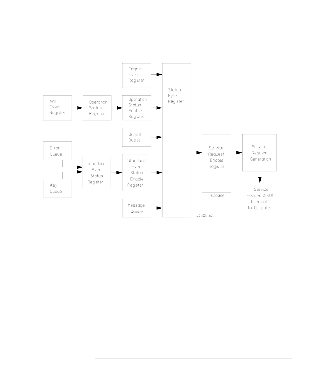
Figure 4-1
Status Reporting
Status Reporting Overview Block Diagram
The status reporting structure consists of the registers shown here.
Table 4-1 lists the bit definitions for each bit in the status reporting data
structure.
Table 4-1 Status Reporting Bit Definition
Bit Description Definition
PON Power On Indicates power is turned on.
URQ User Request Not Used. Permanently set to zero.
CME Command Error Indicates if the parser detected an error.
EXE Execution Error Indicates if a parameter was out of range or was
inconsistent with the current settings.
4-3
Page 66

Status Reporting
Bit Description Definition
DDE Device Dependent Error Indicates if the device was unable to complete an
operation for device-dependent reasons.
QYE Query Error Indicates if the protocol for queries has been violated.
RQL Request Control Indicates if the device is requesting control.
OPC Operation Complete Indicates if the device has completed all pending
OPER Operation Status RegisterIndicates if any of the enabled conditions in the
RQS Request Service Indicates that the device is requesting service.
MSS Master Summary S tatus Indicat es if a device has a reason for requesting s ervice.
ESB Event Status Bit Indicates if any of the enabled conditions i n the Standard
MAV Message Available Indicates if there is a response in the output queue.
MSG Message Indicates if an advisory has been displayed.
USR User Event Register Indicates if any of the enabled conditions ha ve occurred
TRG Trigger Indicates if a trigger has been received.
WAIT TRIG Wait for Trigger Indicates the oscilloscope is armed and ready for
operations.
Operation Status Register have occurred.
Event Status Register have occurred.
in the User Event Register.
trigger.
4-4
Page 67

Status Reporting
Status Reporting Data Structures
Status Reporting Data Structures
The different status reporting data structures, descriptions, and interactions
are shown in Figure 4-2. To make it possible for any of the Standard Event
Status Register bits to generate a summary bit, you must enable the
corresponding bits. These bits are enabled by using the *ESE common
command to set the corresponding bit in the Standard Event Status Enable
Register.
To generate a service request (SRQ) interrupt to the computer, you must enable
at least one bit in the Status Byte Register. These bits are enabled by using the
*SRE common command to set the corresponding bit in the Service Request
Enable Register. These enabled bits can then set RQS and MSS (bit 6) in the
Status Byte Register.
For more information about common commands, see the “Common Commands”
chapter.
4-5
Page 68
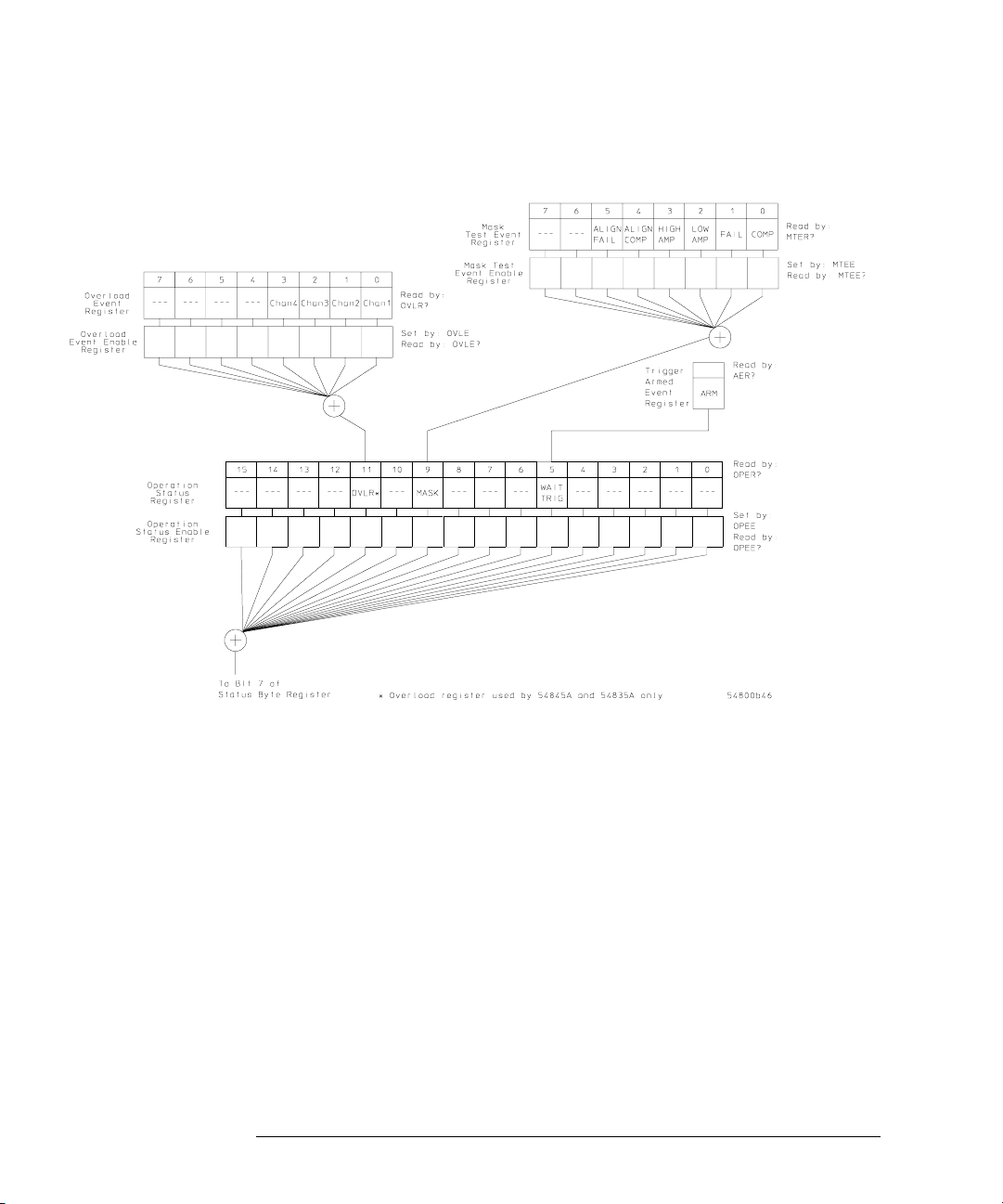
Figure 4-2
Status Reporting
Status Reporting Data Structures
Status Reporting Data Structures
4-6
Page 69
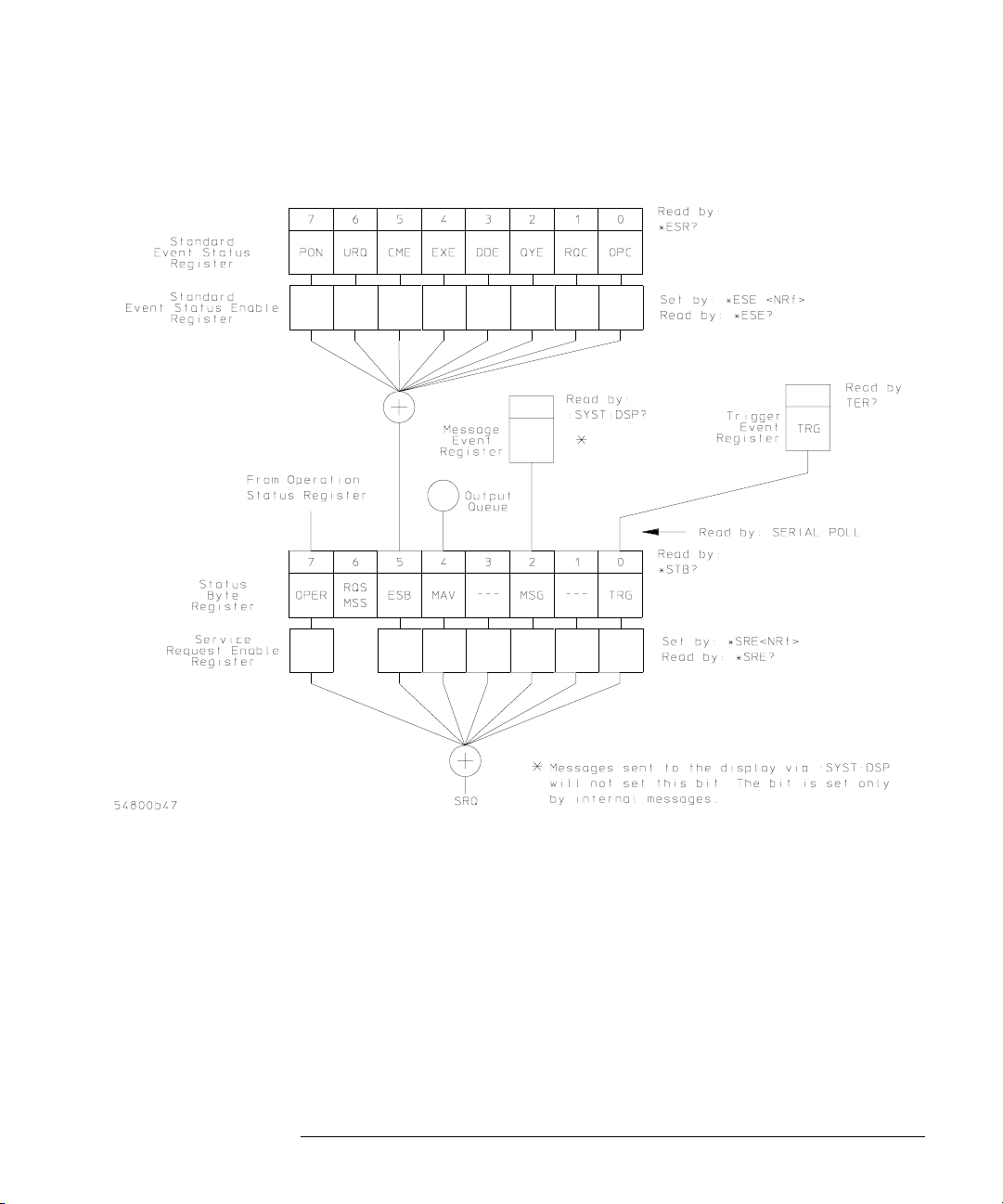
Figure 4-2 (Continued)
Status Reporting
Status Reporting Data Structures
Status Reporting Data Structures (Continued)
4-7
Page 70

Status Reporting
Status Byte Register
Status Byte Register
The Status Byte Register is the summary-level register in the status reporting
structure. It contains summary bits that monitor activity in the other status
registers and queues. The Status Byte Register is a live register. That is, its
summary bits are set and cleared by the presence and absence of a summary
bit from other event registers or queues.
If the Status Byte Register is to be used with the Service Request Enable
Register to set bit 6 (RQS/MSS) and to generate an SRQ, at least one of the
summary bits must be enabled, then set. Also, event bits in all other status
re g i s ters must be sp e cifically ena b l e d to generate th e summary bit th a t sets the
associated summary bit in the Status Byte Register.
You can read the Status Byte Register using either the *STB? common command
query or the GPIB serial poll command. Both commands return the decimalweighted sum of all set bits in the register. The difference between the two
methods is that the serial poll command reads bit 6 as the Request Service
(RQS) bit and clears the bit which clears the SRQ interrupt. The *STB? query
reads bit 6 as the Master Summary Status (MSS) and does not clear the bit or
have any effect on the SRQ interrupt. The value returned is the total bit weights
of all of the bits that are set at the present time.
The use of bit 6 can be confusing. This bit was defined to cover all possible
computer interfaces, including a computer that could not do a serial poll. The
important point to remember is that if you are using an SRQ interrupt to an
external computer, the serial poll command clears bit 6. Clearing bit 6 allows
the oscilloscope to generate another SRQ interrupt when another enabled event
occurs.
The only other bit in the Status Byte Register affected by the *STB? query is
the Message Available bit (bit 4). If there are no other messages in the Output
Queue, bit 4 (MAV) can be cleared as a result of reading the response to the
*STB? query.
If bit 4 (weight = 16) and bit 5 (weight = 32) are set, a program would print the
sum of the two weights. Since these bits were not enabled to generate an SRQ,
bit 6 (weight = 64) is not set.
4-8
Page 71
Status Reporting
Status Byte Register
Example 1 This HP BASIC example uses the *STB? query to read the contents of the
oscilloscope’s Status Byte Register when none of the register's summary bits
are enabled to generate an SRQ interrupt.
10 OUTPUT 707;":SYSTEM:HEADER OFF;*STB?" !Turn headers off
20 ENTER 707;Result !Place result in a numeric variable
30 PRINT Result !Print the result
40 End
The next program prints 132 and clears bit 6 (RQS) of the Status Byte Register.
The difference in the decimal value between this example and the previous one
is the value of bit 6 (weight = 64). Bit 6 is set when the first enabled summary
bit is set, and is cleared when the Status Byte Register is read by the serial poll
command.
Example 2 This example uses the HP BASIC serial poll (SPOLL) command to read the
contents of the oscilloscope’s Status Byte Register.
10 Result = SPOLL(707)
20 PRINT Result
30 END
Use Serial Polling to Read the Status Byte Register
Serial polling is the preferred method to read the contents of the Status Byte Register
because it resets bit 6 and allows the next enabled event that occurs to generate a
new SRQ interrupt.
4-9
Page 72

Status Reporting
Service Request Enable Register
Service Request Enable Register
Setting the Service Request Enable Register bits enables corresponding bits in
the Status Byte Register. These enabled bits can then set RQS and MSS (bit 6)
in the Status Byte Register.
Bits are set in the Service Request Enable Register using the *SRE command,
and the bits that are set are read with the *SRE? query. Bit 6 always returns 0.
Refer to the Status Reporting Data Structures shown in Figure 4-2.
Example This example sets bit 4 (MAV) and bit 5 (ESB) in the Service Request Enable
Register.
OUTPUT 707;"*SRE 48"
This example uses the parameter “48” to allow the oscilloscope to generate an
SRQ interrupt under the following conditions:
• When one or more bytes in the Output Queue set bit 4 (MAV).
• When an enabled event in the Standard Event Status Register generates a
summary bit that sets bit 5 (ESB).
Message Event Register
This register sets the MSG bit in the status byte register when an internally
generated message is written to the advisory line on the oscilloscope. The
message is read using the :SYSTEM:DSP? query. Note that messages written
to the advisory line on the oscilloscope using the :SYSTEM:DSP command does
not set the MSG status bit.
Trigger Event Register
This register sets the TRG bit in the status byte register when a trigger event
occurs.
The trigger event register stays set until it is cleared by reading the register with
the TER? query or by using the *CLS (clear status) command. If your
application needs to detect multiple triggers, the trigger event register must be
cleared after each one.
If you are using the Service Request to interrupt a computer operation when
the trigger bit is set, you must clear the event register after each time it is set.
4-10
Page 73

Status Reporting
Standard Event Status Register
Standard Event Status Register
Th e Sta n da r d Ev e n t S t a t u s Re g is t e r ( S E S R ) mo n i t o r s th e fo l l o w i n g o s c i l l o sc o p e
status events:
• PON - Power On
• CME - Command Error
• EXE - Execution Error
• DDE - Device Dependent Error
• QYE - Query Error
• RQC - Request Control
• OPC - Operation Complete
When one of these events occurs, the corresponding bit is set in the register.
If the corresponding bit is also enabled in the Standard Event Status Enable
Register, a summary bit (ESB) in the Status Byte Register is set.
You can read the contents of the Standard Event Status Register and clear the
register by sending the *ESR? query. The value returned is the total bit weights
of all bits set at the present time.
Example This example uses the *ESR? query to read the cont ents of the Standard Event
Status Register.
10 OUTPUT 707;":SYSTEM:HEADER OFF" !Turn headers off
20 OUTPUT 707;"*ESR?"
30 ENTER 707;Result !Place result in a numeric variable
40 PRINT Result !Print the result
50 End
If bit 4 (weight = 16) and bit 5 (weight = 32) are set, the program prints the
sum of the two weights.
4-11
Page 74

Status Reporting
Standard Event Status Enable Register
Standard Event Status Enable Register
For any of the Standard Event Status Register bits to generate a summary bit,
you must first enable the bit. Use the *ESE (Event Status Enable) common
command to set the corresponding bit in the Standard Event Status Enable
Register. Set bits are read with the *ESE? query.
Example Suppose your application requires an interrupt whenever any type of error
occurs. The error status bits in the Standard Event Status Register are bits
2 through 5. The sum of the decimal weights of these bits is 60. Therefore, you
can enable any of these bits to generate the summary bit by sending:
OUTPUT 707;"*ESE 60"
Whenever an error occurs, the oscilloscope sets one of these bits in the Standard
Event Status Register. Because the bits are all enabled, a summary bit is
generated to set bit 5 (ESB) in the Status Byte Register.
If bit 5 (ESB) in the Status Byte Register is enabled (via the *SRE command),
a service request interrupt (SRQ) is sent to the external computer.
Disabled Standard Event Status Register Bits Respond, but Do Not Generate a
Summary Bit
Standard Event Status Register bits that are not enabled still respond to their
corresponding conditions (that is, they are set if the corresponding event occurs).
However, because they are not enabled, they do not generate a summary bit in the
Status Byte Register.
4-12
Page 75

Status Reporting
Operation Status Register
Operation Status Register
This register hosts the following bits:
• WAIT TRIG bit (bit 5)
• Mask Test Summary bit (bit 9)
• Overload Summary bit (bit 11)
The WAIT TRIG bit is set by the Trigger Armed Event Register and indicates
the trigger is armed.
The Mask Test Summary bit is set whenever at least one of the Mask Test Event
Register bits is enabled.
The Overload Summary bit is set whenever at least one of the Overload Event
Register bits is enabled (this register is only used by the 54845A and the
54835A).
If any of these bits are set, the OPER bit (bit 7) of the Status Byte Register is
set. The Operation Status Register is read and cleared with the OPER? query.
The register output is enabled or disabled using the mask value supplied with
the OPEE command.
4-13
Page 76

Status Reporting
Operation Status Enable Register
Operation Status Enable Register
For any of the Operation Status Register bits to generate a summary bit, you
must first enable the bit. Use the OPEE (Operation Event Status Enable)
command to set the corresponding bit in the Operation Status Enable Register.
Set bits are read with the OPEE? query.
Example Suppose your application requires an interrupt whenever any event occurs in
the mask test register. The error status bit in the Operation Status Register is
bit 9. Therefore, you can enable this bit to generate the summary bit by sending:
OUTPUT 707;”OPEE 512” ( hex 200 )
Whenever an error occurs, the oscilloscope sets this bit in the Mask Test Event
Register. Because this bit is enabled, a summary bit is generated to set bit 9
(OPER) in the Operation Status Register.
If bi t 7 (O P E R) in th e Status Byte Register is en a b led (via the *SRE command),
a service request interrupt (SRQ) is sent to the external computer.
Disabled Operation Status Register Bits Respond, but Do Not Generate a Summary
Bit
Operation Status Register bits that are not enabled still respond to their
corresponding conditions (that is, they are set if the corresponding event occurs).
However, because they are not enabled, they do not generate a summary bit in the
Status Byte Register.
4-14
Page 77

Status Reporting
Mask Test Event Register
Mask Test Event Register
This register hosts the following bits:
• Mask Test Complete bit (bit 0)
• Mask Test Fail bit (bit 1)
• Mask Low Amplitude bit (bit 2)
• Mask High Amplitude bit (bit 3)
• Mask Align Complete bit (bit 4)
• Mask Align Fail bit (bit 5)
The Mask Test Complete bit is set whenever the mask test is complete.
The Mask Test Fail bit is set whenever the mask test failed.
The Mask Low Amplitude bit is set whenever the signal is below the mask
amplitude.
The Mask High Amplitude bit is set whenever the signal is above the mask
amplitude.
The Mask Align Complete bit is set whenever the mask align is complete.
The Mask Align Fail bit is set whenever the mask align failed.
If any of the se b its a re se t, the MAS K bit (bit 9) o f the Oper ation S tat us Re gist er
is set. The Ma s k Test Event Re gister is re a d a nd clea r e d with the MT E R ? query.
The register output is enabled or disabled using the mask value supplied with
the MTEE command.
4-15
Page 78

Status Reporting
Mask Test Event Enable Register
Mask Test Event Enable Register
For any of the Mask Test Event Register bits to generate a summary bit, you
must first enable the bit. Use the MTEE (Mask Test Event Enable) command
to set the corresponding bit in the Mask Test Event Enable Register. Set bits
are read with the MTEE? query.
Example Suppose your application requires an interrupt whenever a Mask Test Fail
o cc u rs i n t he ma sk t es t re gi st e r. Yo u c a n e n ab l e t h is bi t t o g en er at e th e su m ma r y
bit by sending:
OUTPUT 707;”MTEE 2”
Whenever an error occurs, the oscilloscope sets the MASK bit in the Operation
Status Register. Because the bits in the Operation Status Enable Register are
all enabled, a summary bit is generated to set bit 7 (OPER) in the Status Byte
Register.
If bi t 7 (O P E R) in th e Status Byte Register is en a b led (via the *SRE command),
a service request interrupt (SRQ) is sent to the external computer.
Disabled Mask Test Event Register Bits Respond, but Do Not Generate a Summary
Bit
Mask Test Event Register bits that are not enabled still respond to their
corresponding conditions (that is, they are set if the corresponding event occurs).
However, because they are not enabled, they do not generate a summary bit in the
Operation Status Register.
4-16
Page 79

Status Reporting
Trigger Armed Event Register
Trigger Armed Event Register
This register sets bit 5 (Wait Trig bit) in the Operation Status Register and bit
7 (OPER bit) in the Status Byte Register when the oscilloscope becomes armed.
The ARM event register stays set until it is cleared by reading the register with
the AER? query or by using the *CLS command. If your application needs to
detect multiple triggers, the ARM event register must be cleared after each one.
If you are using the Service Request to interrupt the computer operation when
the trigger bit is set, you must clear the event register after each time it is set.
Error Queue
As errors are detected, they are placed in an error queue. This queue is a firstin, first-out queue. If the error queue overflows, the last error in the queue is
replaced with error -350, “Queue overflow.” Any time the queue overflows, the
oldest errors remain in the queue, and the most recent error is discarded. The
length of the oscilloscope's error queue is 30 (29 positions for the error
messages, and 1 position for the “Queue overflow” message).
The error queue is read with the :SYSTEM:ERROR? query. Executing this query
reads and removes the oldest error from the head of the queue, which opens a
position at the tail of the queue for a new error. When all the errors have been
read from the queue, subsequent error queries return 0, “No error.”
The error queue is cleared when any of these events occur:
• When the oscilloscope is powered up.
• When the oscilloscope receives the *CLS common command.
• When the last item is read from the error queue.
For more information on reading the error queue, refer to the
:SYSTEM : E RROR? que r y i n the Syste m C ommand s ch apter. For a com p lete list
of error messages, refer to the chapter, “Error Messages.”
Output Queue
The output queue stores the oscilloscope-to-computer responses that are
generated by certain oscilloscope commands and queries. The output queue
generates the Message Available summary bit when the output queue contains
one or more bytes. This summary bit sets the MAV bit (bit 4) in the Status Byte
Register. You may read the output queue with the HP Basic ENTER statement.
4-17
Page 80

Status Reporting
Message Queue
Message Queue
The messa g e queue con t a i ns the text of th e la st messa g e wr itten to th e ad visory
line on the screen of the oscilloscope. The queue is read with the
:SYSTEM:DSP? query. Note that messages sent with the :SYSTEM:DSP
command do not set the MSG status bit in the Status Byte Register.
Clearing Registers and Queues
The *CLS common command clears all event registers and all queues except
the output queue. If *CLS is sent immediately following a program message
terminator, the output queue is also cleared.
4-18
Page 81
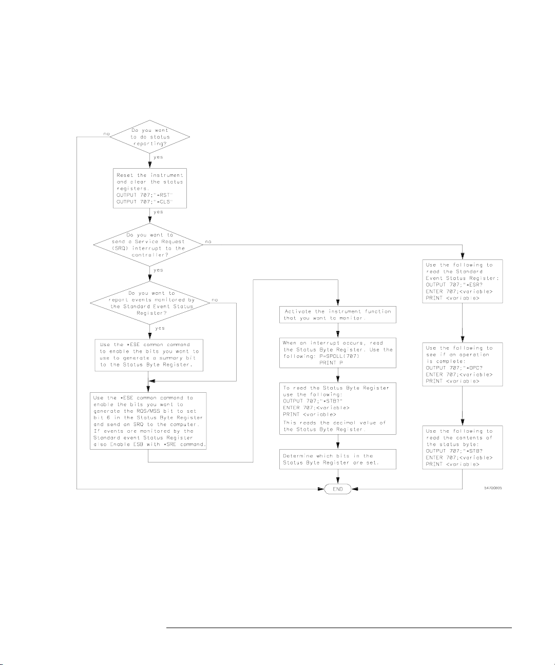
Figure 4-3
Status Reporting
Clearing Registers and Queues
Status Reporting Decision Chart
4-19
Page 82

4-20
Page 83

5
Programming Conventions
Page 84

Programming Conventions
This chapter describes conventions used to program the Infiniium-Series
Oscilloscopes, and conventions used throughout this manual. A block
diagram and description of data flow is included for understanding
oscilloscope operations. A description of the command tree and
command tree traversal is also included. Also see the Programmer’s
Quick Reference Guide for more information about command syntax.
5-2
Page 85
Figure 5-1
Sample
Data
Programming Conventions
Data Flow
Data Flow
The data flow gives you an idea of where the measurements are made on the
acquired data, and when the post-waveform processing is applied to the data.
Figure 5- 1 is a block di a g r am of the os c illosco p e . The diagr a m is laid out se r ially
for a visual perception of how the data is affected by the oscilloscope.
Averaging
Waveform
Memories
Channel
Memory
Sinx/x Interpolation
Filter (Optional)
9-Bit High Resolution
Filter (Optional)
Math/FFT
Functions
Sample Data Processing
Measurements
(Optional)
Connect Dots
(Optional)
Display
54800b01.vsd
5-3
Page 86

Programming Conventions
Data Flow
The sample data is stored in the channel memory for further processing before
being displayed. The time it takes for the sample data to be displayed depends
on the number of post processes you have selected.
Averaging your sampled data helps remove any unwanted noise from your
waveform. The 9-bit, high-resolution filter also removes noise from your
waveform by limiting the bandwidth of the oscilloscope to:
F
/20
s
where:
F
= the sampling frequency
s
This filter lowers the noise floor of the oscilloscope, which increases the
oscilloscope’s vertical resolution.
You ca n store you r sample da t a in Infin i i u m’s wa v eform me m ories fo r us e as one
of the sources in Math/FFT functions, or to visually compare against a waveform
that is captured at a future time. The Math/FFT functions let you apply
mathematical ope rations on your sampled data . You can use these functions to
duplicate many of the mathematical operations that your circuit may be
performing to verify that your circuit is operating correctly.
The measurements section performs any of the automated measurements that
are available in Infiniium. The measurements that you have selected appear at
the bottom of the display.
The Connect Dots section draws a straight line between sample data points,
giving an analog look to the waveform. This is sometimes called linear
interpolation.
5-4
Page 87
Programming Conventions
Truncation Rule
Truncation Rule
The truncation rule is used to produce the short form (abbreviated spelling) for
the mnemonics used in the programming headers and alpha arguments.
Command Truncation Rule
The mnemonic is the first fo ur characters of the keyword, unless the fourth character
is a vowel. Then the mnemonic is the first three characters of the keyword. If the
length of the keyword is four characters or less, this rule does not apply, and the
short form is the same as the long form.
Table 5-1 shows how the truncation rule is applied to commands.
Table 5-1
Mnemonic Truncation
Long Form Short Form How the Rule is Applied
RANGE RANG Short form is the first four characters of the keyword.
PATTERN PATT Short form is the first four characters of the keyword.
DISK DISK Short form is the same as the long form.
DELAY DEL Fourth character is a vowel; short form is the first three
characters.
5-5
Page 88

Programming Conventions
The Command Tree
The Command Tree
The command tree in Figure 5-2 shows all of the commands in the InfiniiumSeries Oscilloscopes and the relationship of the commands to each other. The
IEEE 488.2 common commands are not listed as part of the command tree
because they do not affect the position of the parser within the tree.
When a program message terminator (<NL>, linefeed - ASCII decimal 10) or a
leading colon (:) is sent to the oscilloscope, the parser is set to the “root” of the
command tree.
Command Types
The commands in this oscilloscope can be viewed as three types: common
commands, root level commands, and subsystem commands.
• Common co mmands ar e comma n d s define d by IEEE 48 8 . 2 and con t r ol some
fu n c t i ons that are common to all IEEE 488.2 instrume n t s . Th e s e co m mands
are inde p end e nt of the tr ee an d do no t af f ect t he po si t i on of the pa rse r wit hin
the tree. *RST is an example of a common command.
• Root level commands control many of the basic functions of the oscilloscope.
These commands reside at the root of the command tree. They can always
be parsed if they occur at the beginning of a program message or are
preceded by a colon. Unlike common commands, root level commands place
the parser ba c k at the root of th e co mmand tre e . A UTOSCA L E i s an exampl e
of a root level command.
• Subsystem commands are grouped together under a common node of the
command tree , such as the TIMEBASE command s. You may sel ect only one
subsystem at a given time. When you turn on the oscilloscope initially, the
command parser is set to the root of the command tree and no subsystem is
selected.
See Also The Programmer’s Quick Reference Guide for information about command
syntax and command syntax diagrams.
5-6
Page 89
Programming Conventions
The Command Tree
Tree Traversal Rules
Command headers are created by traversing down the command tree. A legal
command header from the command tree would be :TIMEBASE:RANGE. This
is referred to as a compound header. A compound header is a header made up
of t w o or mo r e mn e m o n i c s s e p a r a te d by co l o n s . Th e com p o u n d he a de r con t ai n s
no spaces. The following rules apply to traversing the tree.
Tree Traversal Rules
A leading colon or a program message terminator (<NL> or EOI true on the last byte)
places the parser at the root of the command tree. A leading colon is a colon that is
the first character of a program header. Executing a subsystem command places
the oscilloscope in that subsystem until a leading colon or a program message
terminator is found.
In the command tree, use the last mnemonic in the compound header as a
reference point (for example, RANGE). Then find the last colon above that
mnemonic (TIMEBASE:). That is the point where the parser resides. You can
send any command below this point within the current program message
without sending the mnemonics which appear above them (for example,
REFERENCE).
5-7
Page 90
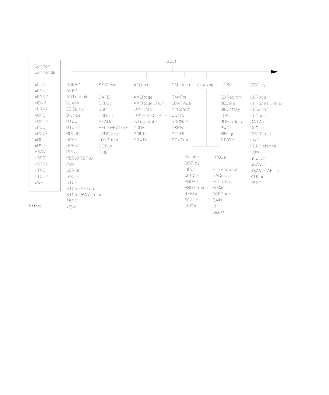
Figure 5-2
Programming Conventions
The Command Tree
Command Tree
5-8
Page 91
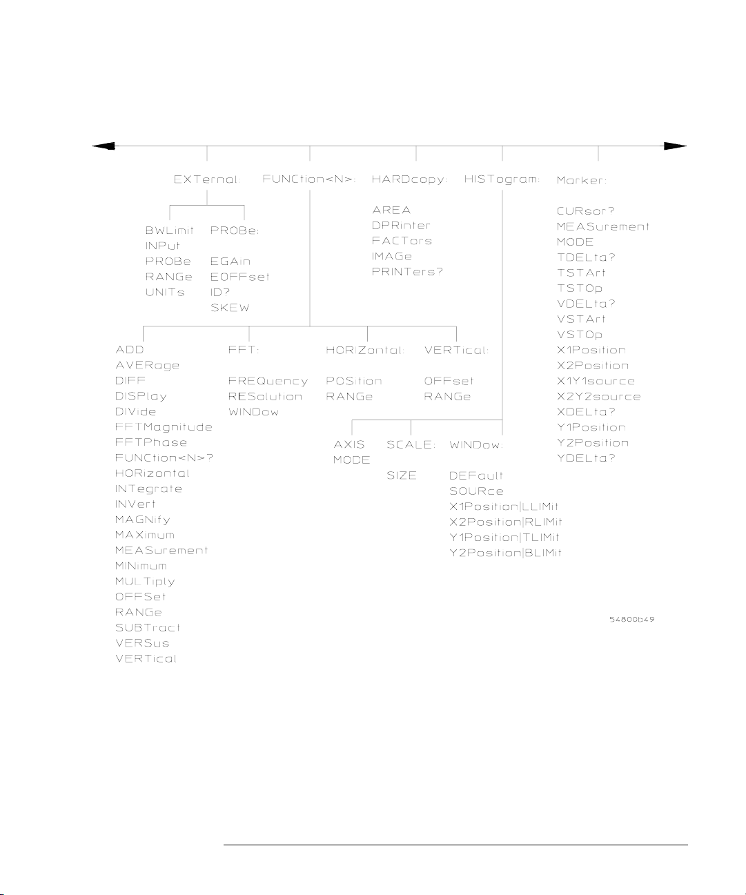
Figure 5-3
Programming Conventions
The Command Tree
Command Tree (Continued)
5-9
Page 92
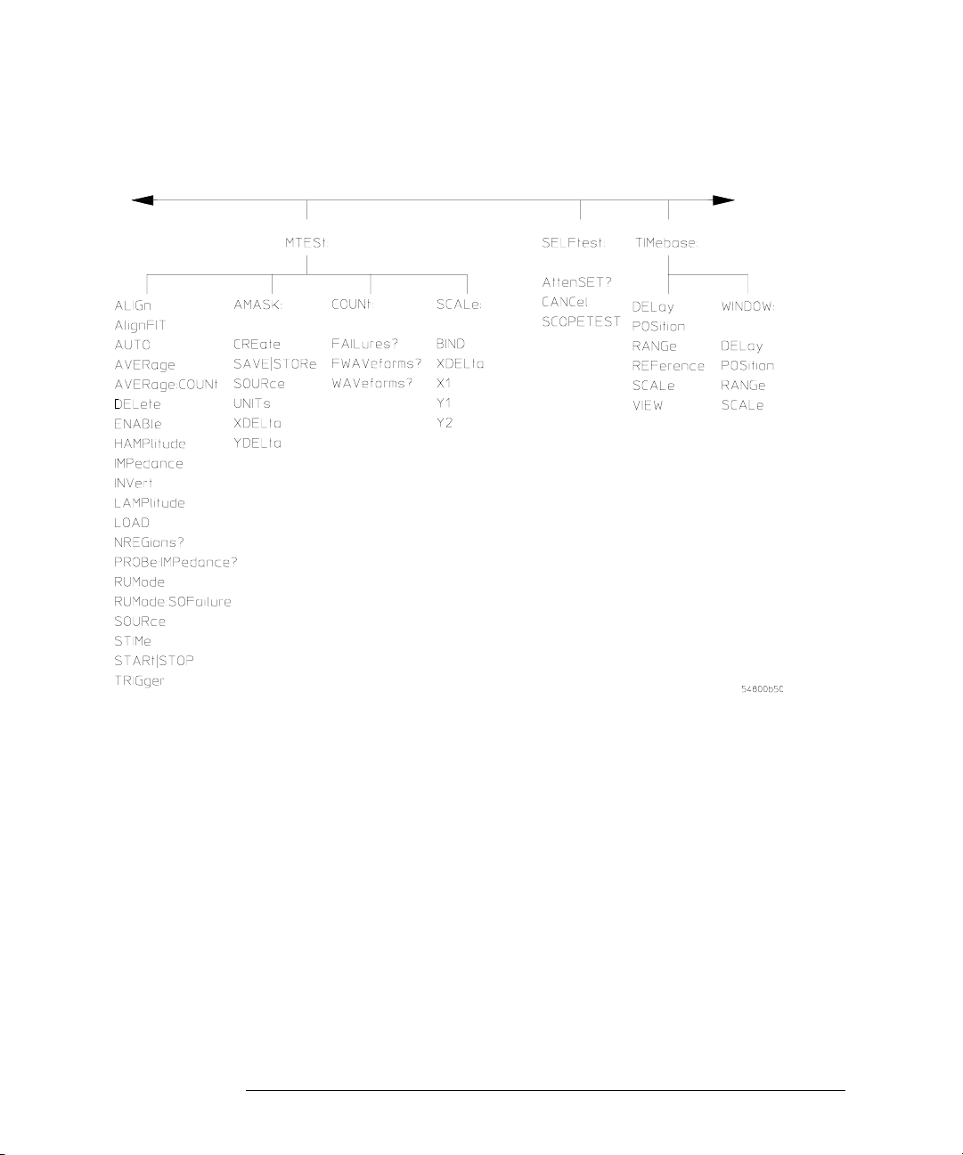
Figure 5-4
Programming Conventions
The Command Tree
Command Tree (Continued)
5-10
Page 93
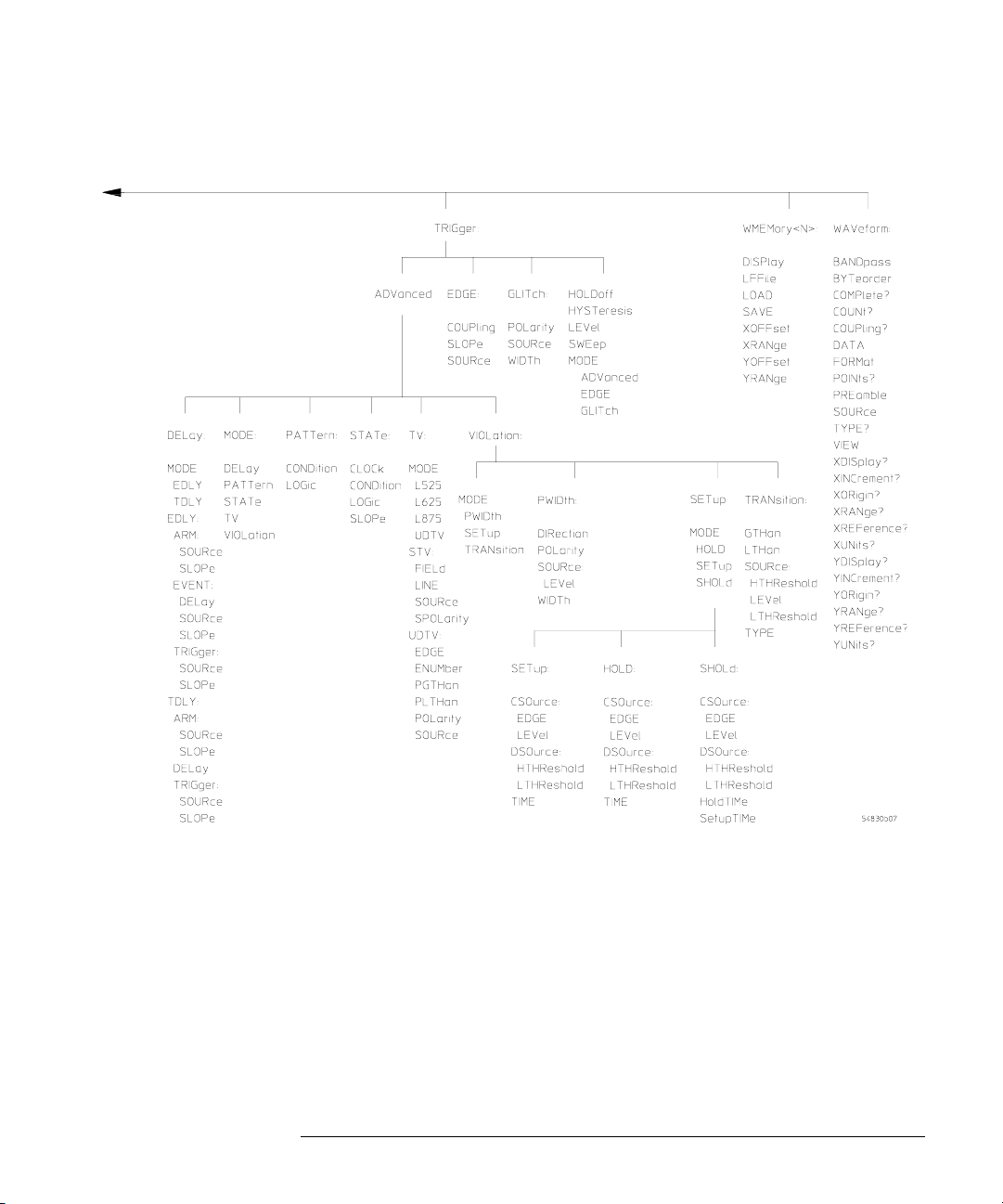
Figure 5-5
Programming Conventions
The Command Tree
Command Tree (Continued)
5-11
Page 94

Programming Conventions
The Command Tree
Tree Traversal Examples
The OUTPUT statements in the following examples are written using
HP BASIC 5.0. The quoted string is placed on the bus, followed by a carriage
return and linefeed (CRLF).
Example 1 Consider the following command:
OUTPUT 707;":CHANNEL1:RANGE 0.5;OFFSET 0"
The colon between CHANNEL1 and RANGE is necessary because
:CHANNEL1:RANGE is a compound command. The semicolon between the
RANGE command and the OFFSET command is required to separate the two
commands or operations. The OFFSET command does not need :CHANNEL1
preceding it because the :CHANNEL1:RANGE command sets the parser to the
CHANNEL1 node in the tree.
Example 2 Consider the following commands:
OUTPUT 707;":TIMEBASE:REFERENCE CENTER;POSITION 0.00001"
or
OUTPUT 707;":TIMEBASE:REFERENCE CENTER"
OUTPUT 707;":TIMEBASE:POSITION 0.00001"
In the first line of example 2, the “subsystem selector” is implied for the
POSITION command in the compound command.
A second way to send these commands is shown in the second part of the
example. Because the program message terminator places the parser back at
the root of the command tree, you must reselect TIMEBASE to re-enter the
TIMEBASE node before sending the POSITION command.
Example 3 Consider the following command:
OUTPUT 707;":TIMEBASE:REFERENCE CENTER;:CHANNEL1:OFFSET 0"
In this example, the leading colon before CHANNEL1 tells the parser to go back
to the root of the command tree. The parser can then recognize the
:CHANNEL1:OFFSET command and enter the correct node.
5-12
Page 95

Programming Conventions
Infinity Representation
Infinity Representation
The representation for infinity for this oscilloscope is 9.99999E+37. This is also
the value returned when a measurement cannot be made.
Sequential and Overlapped Commands
IE EE 48 8 . 2 ma ke s a di s t i n c ti on b et we en s eq ue nt i a l an d o v e rl ap pe d co m m a n ds .
Sequential commands finish their task before the execution of the next
command starts. Overlapped commands run concurrently. Commands
following an overlapped command may be started before the overlapped
command is completed.
Response Generation
As defined by IEEE 488.2, query responses may be buffered for these reasons:
• When the query is parsed by the oscilloscope.
• When the computer addresses the oscilloscope to talk so that it may read the
response.
This oscilloscope buffers responses to a query when the query is parsed.
EOI
The EOI bus control line follows the IEEE 488.2 standard without exception.
5-13
Page 96

5-14
Page 97

6
Sample Programs
Page 98

Sample Programs
Sample programs for the Infiniium-Series Oscilloscopes are shipped on
a CD ROM with the instrument. Each program demonstrates specific
sets of instructions.
This chapter shows you some of those functions, and describes the
commands being executed. Both C and BASIC examples are included.
The header file is:
• gpibdecl.h
The C examples include:
•init.c
•gen_srq.c
• srqagi.c
•srqnat.c
• learnstr.c
• sicl_IO.c
•natl_IO.c
The BASIC examples include:
•init.bas
•srq.bas
•lrn_str.bas
The sample program listings are included at the end of this chapter.
6-2
Page 99

Sample Program Structure
This chapter includes segments of both the C and BASIC sample
programs. Each program includes the basic functions of initializing
the interface and oscilloscope, capturing the data, and analyzing the
data.
In general, both the C and BASIC sample programs typically contain
the following fundamental segments:
Segment Description
main program Defines global variables and constants, specifies include files,
initialize Initializes the GPIB or LAN interface and oscilloscope, and sets
acquire_data Digitizes the waveform to capture data.
auto_measurements Performs simple parametric measurements.
transfer_data Brings waveform data and voltage/timing information (the
and calls various functions.
up the oscilloscope and the ACQuire subsystem.
preamble) into the computer.
6-3
Page 100

Sample Programs
Sample C Programs
Sample C Programs
Segments of the sample programs “init.c” and “gen_srq.c” are shown and
described in this chapter.
init.c - Initialization
/* init. c */
/* Command Order Example. This program demonstrates the order of commands
suggested for operation of the 548xx oscilloscope via GPIB.
This program initializes the oscilloscope, acquires data, performs
automatic measurements, and transfers and stores the data on the
PC as time/voltage pairs in a comma-separated file format useful
for spreadsheet applications. It assumes a SICL INTERFACE exists
as ’hpib7’ and an 548xx oscilloscope at address 7.
It also requires the cal waveform attached to Channel 1.
See the README file on the demo disk for development and linking information.
*/
#include <stdio.h> /* location of: printf() */
#include <stdlib.h> /* location of: atof(), atoi() */
#include "gpibdecl.h" /* prototypes, global declarations, constants */
void initialize( ); /* initialize the oscilloscope */
void acquire_data( ); /* digitize waveform */
void auto_measurements( ); /* perform built-in automatic measurements */
void transfer_data( ); /* transfers waveform data from oscilloscope to PC */
void convert_data( ); /* converts data to time/voltage values */
void store_csv( ); /* stores time/voltage pairs to comma-separated
/* variable file format */
The include statements start the program. The file “gpibdecl.h” includes
prototypes and declarations that are necessary for the Infiniium Oscilloscope
sample programs.
This segment of the sample program defines the functions, in order, that are
used to initialize the oscilloscope, digitize the data, perform measurements,
transf er data from the oscilloscope to the PC, convert th e digit ized da ta to time
and voltage pairs, and store the converted data in comma-separated variable
file format.
See the following descriptions of the program segments.
6-4
 Loading...