

Page 1

5973 inert
Mass Selective Detector
Hardware Manual
Agilent Technologies
Page 2

5973 inert
Mass Selective Detector
Hardware Manual
Page 3

Page 4

Notices
© Agilent Technologies,
Inc. 2003
No part of this manual
may be reproduced in any
form or by any means
(including electronic
storage and retrieval or
translation into a foreign
language) without prior
agreement and written
consent from Agilent
Technologies, Inc. as
governed by United States
and international
copyright laws.
Manual Part Number
G2589-90071
Edition
Second edition, August
2003
Agilent Technologies, Inc.
2850 Centerville Road
Wilmington, DE 19808-1610
USA
Acknowledgements
Microsoft® and
Windows® are U.S.
registered trademarks of
Microsoft Corporation.
Warranty
The material contained in
this document is provided
“as is,” and is subject to
being changed, without
notice, in future editions.
Further, to the maximum
extent permitted by
applicable law, Agilent
disclaims all warranties,
either express or implied,
with regard to this manual
and any information
contained herein,
including but not limited
to the implied warranties
of merchantability and
fitness for a particular
purpose. Agilent shall not
be liable for errors or for
incidental or
consequential damages in
connection with the
furnishing, use, or
performance of this
document or of any
information contained
herein. Should Agilent
and the user have a
separate written
agreement with warranty
terms covering the
material in this document
that conflict with these
terms, the warranty terms
in the separate agreement
shall control.
Safety Notices
CAUTION
A CAUTION notice
denotes a hazard. It calls
attention to an operating
procedure, practice, or
the like that, if not
correctly performed or
adhered to, could result in
damage to the product or
loss of important data. Do
not proceed beyond a
CAUTION notice until the
indicated conditions are
fully understood and met.
WARNING
A WARNING notice
denotes a hazard. It calls
attention to an operating
procedure, practice, or
the like that, if not
correctly performed or
adhered to, could result in
personal injury or death.
Do not proceed beyond a
WARNING notice until the
indicated conditions are
fully understood and met.
Page 5

Table of Contents
Chapter Introduction
5973 inert MSD Version, 14
About this manual, 15
Other User Information, 16
The 5973 inert MSD, 17
CI MSD hardware description, 19
Important Safety Warnings, 21
Safety and Regulatory Certifications, 24
Cleaning/Recycling the Product, 27
Chapter 1 Installing GC Columns
To prepare a capillary column for installation, 32
To install a capillary column in a split/splitless inlet, 34
To condition a capillary column, 36
To install a capillary column in the GC/MSD interface, 38
To install a capillary column using the installation tool, 40
Chapter 2 Operating the MSD
To view MSD analyzer temperature and vacuum status, 48
To set monitors for MSD temperature and vacuum status, 50
To set the MSD analyzer temperatures, 52
To set the GC/MSD interface temperature from the PC, 54
To monitor high vacuum pressure, 56
To measure column flow linear velocity, 58
To calculate column flow, 59
To tune the MSD, 60
To verify system performance, 61
Verify the tune performance, 61
Verify the sensitivity performance, 61
To remove the MSD covers, 62
Analyzer cover, 62
Lower MSD cover, 62
To vent the MSD, 64
To open the analyzer chamber, 66
To close the analyzer chamber, 68
Page 6

To pump down the MSD, 70
To pump down the CI MSD, 72
To connect the gauge controller, 73
To move or store the MSD, 75
To set the interface temperature from a 6890 GC, 77
Chapter 3 Operating the CI MSD
To switch from EI to CI operating mode, 82
To set up the software for CI operation, 83
To operate the reagent gas flow control module, 84
To set up methane reagent gas flow, 86
CI autotune, 88
To perform a positive CI autotune (methane only), 90
To perform a negative CI autotune (any reagent gas), 92
To verify positive CI performance, 94
To verify negative CI performance, 95
To monitor high vacuum pressure, 96
Typical pressure readings, 97
To use other reagent gases, 98
Isobutane CI, 99
Ammonia CI, 100
Carbon dioxide NCI, 101
To switch from CI to EI operating mode, 102
Chapter 4 Troubleshooting the MSD
General symptoms, 106
GC does not turn on, 106
MSD does not turn on, 106
Foreline pump is not operating, 106
MSD turns on but then the foreline pump shuts off, 107
Control panel says “No server found”, 107
Chromatographic symptoms, 108
No peaks, 108
Peaks are tailing, 109
Peaks are fronting, 109
Peaks have flat tops, 110
Peaks have split tops, 110
Baseline is rising, 110
Baseline is high, 110
6
Page 7

Baseline is falling, 110
Baseline wanders, 111
Retention times for all peaks drift – shorter, 111
Retention times for all peaks drift – longer, 111
Poor sensitivity, 112
Poor Repeatability, 112
Mass spectral symptoms, 113
No peaks, 113
Isotopes are missing or isotope ratios are incorrect, 113
High background, 113
High abundances at m/z 18, 28, 32, and 44 or at m/z 14 and 16, 114
Mass assignments are incorrect, 114
Peaks have precursors, 114
Peak widths are inconsistent, 114
Relative abundance of m/z 502 is less than 3%, 115
Spectra look different from those acquired with other MSDs, 115
High mass sensitivity is poor, 116
Pressure symptoms, 117
Foreline pressure is too high, 117
Analyzer chamber pressure is too high (EI operating mode), 117
Foreline pressure is too low, 118
Analyzer chamber pressure is too low, 118
Gauge controller displays 9.9+9 and then goes blank, 118
Power indicator on the gauge controller does not light, 119
Temperature symptoms, 120
Ion source will not heat up, 120
Mass filter (quad) heater will not heat up, 121
GC/MSD interface will not heat up, 121
Error messages, 122
Difficulty in mass filter electronics, 122
Difficulty with the electron multiplier supply, 122
Difficulty with the fan, 123
Difficulty with the HED supply, 123
Difficulty with the high vacuum pump, 123
High Foreline pressure, 124
Internal MS communication fault, 124
Lens supply fault, 124
Log amplifier ADC error, 124
No peaks found, 124
Temperature control disabled, 125
Temperature control fault, 125
The high vacuum pump is not ready, 126
7
Page 8

The system is in standby, 126
The system is in vent state, 127
There is no emission current, 127
There is not enough signal to begin tune, 127
Air leaks, 128
Contamination, 129
Chapter 5 CI Troubleshooting
Troubleshooting tips and tricks, 133
Air leaks, 134
How do I know if I have an air leak?, 134
How do I find the air leak?, 136
Pressure-related symptoms (overview), 138
Poor vacuum without reagent gas flow, 139
High pressure with reagent gas flow, 140
Pressure does not change when reagent flow is changed, 141
Signal-related symptoms (overview), 142
No peaks, 143
No reagent gas peaks in PCI, 143
No PFDTD peaks in PCI, 144
No reagent gas peaks in NCI, 144
No PFDTD calibrant peaks in NCI, 144
No sample peaks in NCI, 144
Large peak at m/z 238 in NCI OFN spectrum, 144
No or low reagent gas signal, 145
No or low PFDTD signal, but reagent ions are normal, 148
Excessive noise or low signal-to-noise ratio, 150
Large peak at m/z 19, 151
Peak at m/z 32, 152
Tuning-related symptoms (overview), 154
Reagent gas ion ratio is difficult to adjust or unstable, 155
High electron multiplier voltage, 157
Can not complete autotune, 158
Peak widths are unstable, 159
Chapter 6 Maintaining the MSD
Before starting, 162
Maintaining the vacuum system 169
To check and add foreline pump oil, 170
8
Page 9

To drain the foreline pump, 172
To refill the foreline pump, 174
To replace the turbo pump, 177
To separate the MSD from the GC, 178
To reconnect the MSD to the GC, 180
To remove the EI calibration vial, 182
To refill and reinstall the EI calibration vial, 184
To purge the calibration valves, 186
EI calibration valve, 186
CI calibration valve, 186
To remove the EI calibration valve, 187
To reinstall the EI calibration valve, 189
To replace the fan for the high vacuum pump, 191
To remove the triode gauge tube, 193
To reinstall a triode gauge tube, 195
To lubricate the side plate O-ring, 197
To lubricate the vent valve O-ring, 199
Maintaining the analyzer 201
To remove the ion source, 203
To disassemble the ion source, 205
To clean the ion source, 207
To reassemble the ion source, 212
To reinstall the ion source, 214
To remove a filament, 216
To reinstall a filament, 218
To remove the heater and sensor from the ion source, 220
To reinstall the heater and sensor in the ion source, 222
To remove the heater and sensor from the mass filter, 224
To reinstall the heater and sensor in the mass filter, 226
To replace the electron multiplier horn, 228
Maintaining the GC/MSD interface 230
To remove the GC/MSD interface heater and sensor, 232
To reinstall the GC/MSD interface heater and sensor, 234
Maintaining the electronics 236
To adjust the RF coils, 238
To replace the primary fuses, 240
9
Page 10

Chapter 7 CI Maintenance
To set up your MSD for CI operation, 245
To install the CI ion source, 246
To install the CI interface tip seal, 248
To clean the CI ion source, 250
Frequency of cleaning, 250
Cleaning procedure, 250
To minimize foreline pump damage from ammonia, 252
To replace the methane/isobutane gas purifier, 253
To clean the reagent gas supply lines (tubing), 254
To refill the CI calibrant vial, 255
Chapter 8 Vacuum System
Turbo pump MSD vacuum system, 262
Turbo pump analyzer chamber, 263
Side plate, 264
Vacuum seals, 266
Face seals, 266
KF (NW) seals, 266
Compression seals, 266
High voltage feedthrough seal, 267
Foreline pump, 268
Turbomolecular pump and fan, 270
Standard turbo pump, 271
Performance turbo pump, 272
Calibration valves and vent valve, 273
Calibration valves, 273
EI calibration valve, 273
CI calibration valve, 273
Vent valve, 273
Triode gauge tube, 275
Gauge controller, 277
Chapter 9 GC/MSD Interfaces and
CI Flow Control
EI GC/MSD interface, 281
EI/CI GC/MSD interface (CI interface), 282
Reagent gas flow control module, 283
10
Page 11

Chapter 10 Analyzer
Ion source, 290
Ion source body, 290
Filaments, 292
Magnet, 293
Repeller, 293
Drawout plate and cylinder, 294
Ion focus, 294
Entrance lens, 294
Source Washer, 295
CI ion source, 297
Quadrupole mass filter, 299
AMU gain, 299
AMU offset, 300
219 width, 300
DC polarity, 301
Mass (axis) gain, 301
Mass (axis) offset, 301
Quadrupole maintenance, 302
Detector, 303
Detector focus lens, 303
High energy dynode, 303
Electron multiplier horn, 303
Analyzer heaters and radiators, 305
Chapter 11 Electronics
Control panel and power switch, 310
Control panel, 310
Power switch, 310
Side board, 312
Electronics module, 313
Main board, 314
Signal amplifier board, 315
AC board, 316
LAN/MSD control card, 318
Power supplies, 319
Low voltage (ac-dc) power supply, 319
High voltage (HED) power supply, 319
Toroid transformer, 319
Back panel and connectors, 320
11
Page 12

Interfacing to external devices, 322
Remote control processor, 322
Remote start signals, 322
Chapter 12 Parts
Electronics, 327
Vacuum system, 332
Analyzer, 338
EI GC/MSD interface, 344
Consumables and maintenance supplies, 346
CI Parts, 350
Appendix A Chemical Ionization Theory
Chemical ionization overview, 360
References on chemical ionization, 361
Positive CI theory, 362
Proton transfer, 364
Hydride abstraction, 366
Addition, 366
Charge exchange, 367
Negative CI theory, 368
Electron capture, 370
Dissociative electron capture, 371
Ion pair formation, 371
Ion-molecule reactions, 372
12
Page 13

5973 inert MSD Version, 14
About this manual, 15
Other User Information, 16
The 5973 inert MSD, 17
CI MSD hardware description, 19
Important Safety Warnings, 21
Safety and Regulatory Certifications, 24
Cleaning/Recycling the Product, 27
Introduction
This manual describes the operation, troubleshooting, and maintenance of
the Agilent Technologies 5973 inert Mass Selective Detector (MSD)
Page 14

5973 inert MSD Version
5973 inert MSDs are equipped with or one of two turbomolecular (turbo)
pumps. Chemical Ionization is available for the turbo pump MSDs only. The
serial number label displays a product number that tells what kind of MSD
you have. In this manual, the term “CI MSD” applies to the EI/PCI/NCI MSD.
Model number Description
G2578A Standard turbo EI MSD
G2579A Performance turbo EI MSD
G2589A Performance turbo EI/PCI/NCI MSD
14
Page 15

Introduction
About this manual
About this manual
• The introduction describes general information about the 5973 inert
MSD.
• Chapter 1 shows you how to prepare and install a capillary column.
• Chapter 2 describes basic tasks such as setting temperatures, monitoring
pressures, tuning, and venting, and pumpdown.
• Chapter 3 describes basic tasks necessary to operate a CI MSD in CI
mode.
• Chapter 4 provides a quick reference for identifying causes of poor
instrument performance or malfunctions.
• Chapter 5 provides a quick reference for identifying problems unique to
CI MSDs.
• Chapter 6 features maintenance procedures.
• Chapter 7 features maintenance procedures unique to CI MSDs.
• Chapter 8 describes operation of the components of the vacuum system.
• Chapter 9 describes the GC/MSD interface, and the CI flow module.
• Chapter 10 describes operation of the analyzer (ion source, mass filter,
and detector).
• Chapter 11 describes the electronics that control the MSD.
• Chapter 12 contains illustrated parts identification and part numbers.
• Appendix A is an overview of chemical ionization theory.
For updated information, check the Agilent Technologies Life Sciences/
Chemical Analysis web site at http://www.agilent.com/chem.
15
Page 16

Introduction
Other User Information
Other User Information
Additional information is contained in the following documentation:
• 5973N and 5973 inert Mass Selective Detector Hardware Installation
Manual
1
• 5973N and 5973 inert Mass Selective Detector Site Preparation
Guide
1
• 6890 Series GC manuals
• GC accessories (autosampler, etc.) manuals
• G1701DA MSD Productivity ChemStations software manuals and online
help
• 5973N and 5973 inert Mass Selective Detector Specifications (59889991EN)
• Hydrogen Carrier Gas Safety Guide (5955-5398)
1
• 5973N and 5973 inert Mass Selective Detector Local Control Panel
(LCP) Quick Reference
1
• For updated information, see the Agilent Technologies web site at
http://www.agilent.com/chem
1. Located on this CD-ROM [5973 and 5973 inert Mass Selective Detector User
Information]
16
Page 17

Introduction
The 5973 inert MSD
The 5973 inert MSD
The 5973 inert MSD is a stand-alone capillary GC detector
The 5973 inert Mass Selective Detector (MSD) is designed for use with the
6890 Series Gas Chromatograph. The MSD features:
• Control panel for locally monitoring and operating the MSD
• One of two different high vacuum pumps
• Rotary vane foreline pump
• Independently heated electron-ionization ion source
• Independently heated hyperbolic quadrupole mass filter
• High-energy dynode (HED) electron multiplier detector
• Independently heated GC/MSD interface
• Chemical ionization (EI/PCI/NCI) model available
Physical description
The 5973 inert MSD is a rectangular box, approximately 42 cm high, 26 cm
wide, 65 cm deep. The weight is 26 kg for the standard turbo pump
mainframe and 29 kg for the performance turbo pump mainframe. The
attached rough pump weighs an additional
11 kg.
The basic components of the instrument are: the frame/cover assemblies,
the control panel, the vacuum system, the GC interface, the electronics, and
the analyzer.
The control panel allows local monitoring and operation of the MSD
The control panel acts as a local user interface to the MSD. You can perform
some basic tasks such as running a tune, a method, or a sequence; and
monitor MSD status from the control panel.
17
Page 18

Introduction
The 5973 inert MSD
An optional gauge controller is available for measuring vacuum
The 5973 inert MSD is equipped with a triode ionization gauge tube. With an
59864B Gauge Controller, the tube can be used to measure pressure (high
vacuum) in the vacuum manifold. Installation and operation of the gauge
controller is described in this manual.
The gauge controller is
Feature G2578A G2579A G2589A
High vac pump Standard turbo Performance turbo Performance turbo
Optimal He column flow mL/min 1 1 to 2 1 to 2
Maximum recommended gas flow, mL/min
Maximum gas flow,
b
mL/min
Max column id 0.32 mm (30m) 0.53 mm (30 m) 0.53 mm (30 m)
CI capability no no PCI/NCI
DIP capability
(3rd Party)
a. Total gas flow into the MSD: column flow plus reagent gas flow (if applicable).
b. Expect degradation of spectral performance and sensitivity.
required for chemical ionization (CI) operation.
5973 inert MSD models and features
a
2.0 4 4
2.4 6.5 6.5
yes yes no
18
Page 19

Introduction
CI MSD hardware description
CI MSD hardware description
In this manual, the term “CI MSD” applies to the EI/PCI/NCI MSD. The CI
hardware allows the 5973 inert MSD to produce high- quality, classical CI
spectra, which include molecular adduct ions. A variety of reagent gases can
be used.
The 5973 inert CI system adds to the 5973 inert MSD:
• Redesigned EI/CI GC/MSD interface
• CI ion source and interface tip seal
• Reagent gas flow control module
• Bipolar HED power supply (for PCI/NCI MSD
only)
• A methane/isobutane gas purifier is provided, and is required. It removes
oxygen, water, hydrocarbons, and sulfur compounds.
A high vacuum gauge controller (59864B) is
required for the CI MSD.
To achieve the relatively high source pressure required for CI while still
maintaining high vacuum in the quadrupole and detector, the MSD CI
system has been carefully optimized. Special seals along the flow path of the
reagent gas and very small openings in the ion source keep the source gases
in the ionization volume long enough for the appropriate reactions to occur.
The EI/CI interface has special plumbing for reagent gas. A spring-loaded
insulating seal fits onto the tip of the interface.
Switching back and forth between CI and EI takes less than an hour,
although a 1– to 2–hour wait is
required in order to purge the reagent gas
lines and bake out water and other contaminants. Switching from PCI to NCI
requires about 2 hours for the ion source to cool.
19
Page 20

6890 Series
A
LS tower
6890 Series
ALS tray
59864B High Vacuum Gauge
Controller
CI gas flow module
(EI/PCI/NCI MSD only)
5973 inert
Mass Selective Detector
5973 inert MSD control panel
Introduction
CI MSD hardware description
6890
Gas Chromatograph
5973 inert MSD serial number
sticker
20
Page 21

Introduction
Important Safety Warnings
Important Safety Warnings
Before moving on, there are several important safety notices that you should
always keep in mind when using the 5973 inert Mass Selective Detector.
Many internal parts of the MSD carry dangerous voltages
If the MSD is connected to a power source, even if the power switch is off, potentially dangerous voltages exist on:
• The wiring between the MSD power cord and the AC power supply, the AC
power supply itself, and the wiring from the AC power supply to the power
switch.
With the power switch on, potentially dangerous voltages also exist on:
• All electronics boards in the instrument.
• The internal wires and cables connected to these boards.
• The wires for any heater (oven, detector, inlet, or valve box).
WA R N I N G All these parts are shielded by covers. With the covers in place, it should be difficult to
accidentally make contact with dangerous voltages. Unless specifically instructed to, never
remove a cover unless the detector, inlet, or oven are turned off.
WA R N I N G If the power cord insulation is frayed or worn, the cord must be replaced. Contact your
Agilent service representative.
Electrostatic discharge is a threat to MSD electronics
The printed circuit (PC) boards in the MSD can be damaged by electrostatic discharge. Do not touch any of the boards unless it is absolutely necessary. If you must handle them, wear a grounded wrist strap and take
other antistatic precautions. Wear a grounded wrist strap any time you
must remove the MSD right side cover.
21
Page 22

Introduction
Important Safety Warnings
Many parts are dangerously hot
Many parts of the MSD operate at temperatures high enough to cause serious
burns. These parts include but are not limited to:
• The inlets
• The oven and its contents
• The detectors
• The column nuts attaching the column to an inlet or detector
• The valve box
You should always cool these areas of the MSD to room temperature before working on them. They will cool faster if you first set the temperature of the heated
zone to room temperature. Turn the zone off after it has reached the setpoint. If
you must perform maintenance on hot parts, use a wrench and wear gloves. Whenever possible, cool the part of the instrument that you will be maintaining before
you begin working on it.
WA R N I N G Be careful when working behind the instrument. During cool-down cycles, the MSD emits
hot exhaust which can cause burns.
WA R N I N G The insulation around the inlets, detectors, valve box, and the insulation cups is made of
refractory ceramic fibers. To avoid inhaling fiber particles, we recommend the following
safety procedures: ventilate your work area; wear long sleeves, gloves, safety glasses, and
a disposable dust/mist respirator; dispose of insulation in a sealed plastic bag; wash your
hands with mild soap and cold water after handling the insulation.
Hydrogen
Hydrogen gas may be used as carrier gas, and/or as fuel for the FID. When mixed
with air, hydrogen can form explosive mixtures.
22
Page 23

Introduction
Important Safety Warnings
W A R N I N G When using hydrogen (H2) as the carrier gas or fuel gas, be aware that hydrogen gas can flow
into the oven and create an explosion hazard. Therefore, be sure that the supply is off until
all connections are made, and ensure that the inlet and detector column fittings are either
connected to a column or capped at all times when hydrogen gas is supplied to the
instrument.
Hydrogen is flammable. Leaks, when confined in an enclosed space, may create a fire or
explosion hazard. In any application using hydrogen, leak test all connections, lines, and
valves before operating the instrument. Always turn off the hydrogen supply at its source
before working on the instrument.
WA R N I N G The MSD cannot detect leaks in inlet and/or detector gas streams. For this reason, it is vital
that column fittings should always be either connected to a column, or have a cap or plug
installed.
When using hydrogen gas, check the system for leaks to prevent possible fire and
explosion hazards based on local Environmental Health and Safety (EHS) requirements. Always check for leaks after changing a tank or servicing the gas lines.
Always make sure the vent line is vented into a fume hood.
23
Page 24

Introduction
Safety and Regulatory Certifications
Safety and Regulatory Certifications
The 5973 inert Mass Selective Detector conforms to the following safety standards:
• Canadian Standards Association (CSA): C22.2 No. 1010.1
• CSA/Nationally Recognized Test Laboratory (NRTL): UL 61010A–1
• International Electrotechnical Commission (IEC): 61010–1
• EuroNorm (EN): 61010–1
The 5973 inert Mass Selective Detector conforms to the following regulations on
Electromagnetic Compatibility (EMC) and Radio Frequency Interference (RFI):
• CISPR 11/EN 55011: Group 1, Class A
• IEC/EN 61326
•AUS/NZ
This ISM device complies with Canadian ICES-001. Cet appareil ISM est conforme
a la norme NMB—001 du Canada.
The 5973 inert Mass Selective Detector is designed and manufactured under a
quality system registered to ISO 9001.
Information
The Agilent Technologies 5973 inert Mass Selective Detector meets the following
IEC (International Electro-technical Commission) classifications: Safety Class I,
Transient Overvoltage Category II, Pollution Degree 2.
This unit has been designed and tested in accordance with recognized safety standards and is designed for use indoors. If the instrument is used in a manner not
specified by the manufacturer, the protection provided by the instrument may be
impaired. Whenever the safety protection of the 5973 Mass Selective Detector has
been compromised, disconnect the unit from all power sources and secure the unit
against unintended operation.
Refer servicing to qualified service personnel. Substituting parts or performing any
unauthorized modification to the instrument may result in a safety hazard.
24
Page 25
Introduction
Safety and Regulatory Certifications
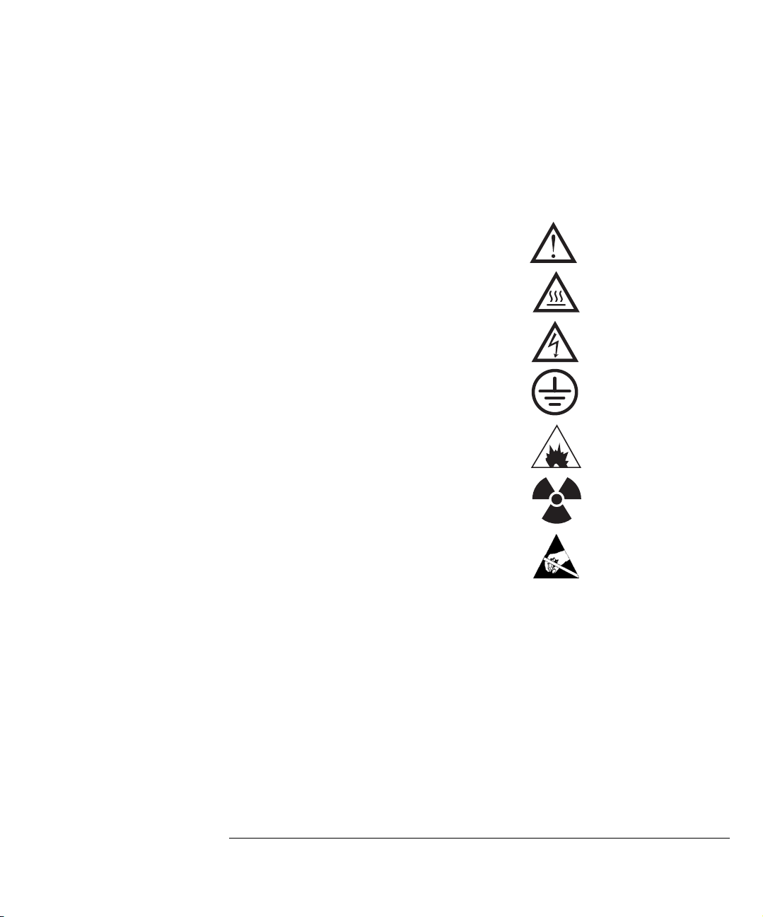
Symbols
Warnings in the manual or on the instrument must be observed during all phases of
operation, service, and repair of this instrument. Failure to comply with these precautions violates safety standards of design and the intended use of the instrument. Agilent Technologies assumes no liability for the customer’s failure to
comply with these requirements.
See accompanying instructions for more information.
Indicates a hot surface.
Indicates hazardous voltages.
Indicates earth (ground) terminal.
Indicates explosion hazard.
Indicates radioactivity hazard.
Indicates electrostatic discharge hazard.
Electromagnetic Compatibility
This device complies with the requirements of CISPR 11. Operation is subject to
the following two conditions:
• This device may not cause harmful interference.
• This device must accept any interference received, including
interference that may cause undesired operation.
If this equipment does cause harmful interference to radio or television reception,
which can be determined by turning the equipment off and on, the user is encouraged to try one or more of the following measures:
25
Page 26

Introduction
Safety and Regulatory Certifications
1 Relocate the radio or antenna.
2 Move the device away from the radio or television.
3 Plug the device into a different electrical outlet, so that the device and the
radio or television are on separate electrical circuits.
4 Make sure that all peripheral devices are also certified.
5 Make sure that appropriate cables are used to connect the device to
peripheral equipment.
6 Consult your equipment dealer, Agilent Technologies, or an experienced
technician for assistance.
7 Changes or modifications not expressly approved by Agilent Technologies
could void the user’s authority to operate the equipment.
Sound Emission Certification for Federal Republic of Germany
Sound pressure
Sound pressure Lp < 70 dB am according to ISO 7779:1988.
Schalldruckpegel
Schalldruckpegel LP < 70 dB am nach EN 27779:1991.
26
Page 27

Introduction
Cleaning/Recycling the Product
Cleaning/Recycling the Product
To clean the unit, disconnect the power and wipe down with a damp, lint-free
cloth. For recycling, contact your local Agilent sales office.
27
Page 28

Introduction
Cleaning/Recycling the Product
28
Page 29

1
To prepare a capillary column for installation, 32
To install a capillary column in a split/splitless inlet, 34
To condition a capillary column, 36
To install a capillary column in the GC/MSD interface, 38
To install a capillary column using the installation tool, 40
Installing GC Columns
How to connect GC columns to the 5973 inert MSD
Page 30

Installing GC columns
Before you can operate your GC/MSD system, you must select, condition,
and install a GC column. This chapter will show you how to install and
condition a column. For correct column and flow selection, you must know
what type of vacuum system your MSD has. The serial number tag on the
lower front of the left side panel shows the model number.
Many types of GC columns can be used with the MSD but there are
some restrictions
During tuning or data acquisition the rate of column flow into the MSD
should not exceed the maximum recommended flow. Therefore, there are
limits to column length and flow. Exceeding recommended flow will result
in degradation of mass spectral and sensitivity performance.
Remember that column flows vary greatly with oven temperature (unless
the GC is set for constant flow). See To measure column flow linear
velocity (page 58) for instructions on how to measure actual flow in your
column. Use the Flow Calculation software to determine whether a given
column will give acceptable flow with realistic head pressure.
Feature G2578A G2579A G2589A
High vac pump Standard turbo Performance turbo Performance turbo, EI/
PCI/NCI
Optimal gas flow, mL/min
Maximum recommended gas
flow, mL/min
Maximum gas flow, mL/min
Max column id 0.32mm (30m) 0.53 mm (30m) 0.53mm (30m)
a. Total gas flow into the MSD: column flow plus reagent gas flow (if applicable).
b. Expect degradation of spectral performance and sensitivity.
30
a
1 1 to 2 1 to 2
2.0 4 4
b
2.4 6.5 4
Page 31

1 Installing GC Columns
Conditioning a column before it is installed into the GC/MSD
interface is essential
A small portion of the capillary column stationary phase is often carried
away by the carrier gas. This is called column bleed. Column bleed deposits
traces of the stationary phase in the MSD ion source. This decreases MSD
sensitivity and makes cleaning the ion source necessary.
Column bleed is most common in new or poorly cross-linked columns. It is
much worse if there are traces of oxygen in the carrier gas when the column
is heated. To minimize column bleed, all capillary columns should be conditioned
before they are installed in the GC/MSD interface.
Conditioning ferrules is also beneficial
Heating ferrules to their maximum expected operating temperature a few
times before they are installed can reduce chemical bleed from the ferrules.
Tips and hints
• Note that the column installation procedure for the 5973 MSDs is
different from that for
another instrument will
all previous MSDs. Using the procedure from
not work, and may damage the column or the
MSD.
• You can remove old ferrules from column nuts with an ordinary push pin.
• Always use carrier gas that is at least 99.999% pure.
• Because of thermal expansion, new ferrules may loosen after heating and
cooling a few times. Check for tightness after two or three heating cycles.
• Always wear clean gloves when handling columns, especially the end that
will be inserted into the GC/MSD interface.
WA R N I N G If you are using hydrogen as a carrier gas, do not start carrier gas flow until the column is
installed in the MSD, and the MSD has been pumped down. If the vacuum pumps are off,
hydrogen will accumulate in the MSD and an explosion may occur. Read the Hydrogen Carrier
Gas Safety Guide (5955-5398) before operating the MSD with hydrogen carrier gas.
WA R N I N G Always wear safety glasses when handling capillary columns. Use care to avoid puncturing
your skin with the end of the column.
31
Page 32

1 Installing GC Columns
To prepare a capillary column for installation
To prepare a capillary column for installation
Materials needed: Capillary column
Column cutter (5181-8836)
Ferrules
0.27-mm id, for 0.10-mm id columns (5062-3518)
0.37-mm id, for 0.20-mm id columns (5062-3516)
0.40-mm id, for 0.25-mm id columns (5181-3323)
0.47-mm id, for 0.32-mm id columns (5062-3514)
0.74-mm id, for 0.53-mm id columns (5062-3512)
Gloves, clean
large (8650-0030)
small (8650-0029)
Inlet column nut (5181-8830)
Magnifying glass
Septum (may be old, used inlet septum)
1 Slide a septum, column nut, and conditioned ferrule onto the free end of
the column.
The tapered end of the ferrule should point away from the column nut.
2 Use the column cutter to score the column 2 cm from the end.
3 Break off the end of the column.
Hold the column against the column cutter with your thumb. Break the column
against edge of the column cutter.
4 Inspect the end for jagged edges or burrs.
If the break is not clean and even, repeat steps 2 and 3.
5 Wipe the outside of the free end of the column with a lint-free cloth
moistened with methanol.
32
Page 33

Capillary column
Column cutter
Fer rul e
Inlet column nut
1 Installing GC Columns
To prepare a capillary column for installation
Septum
33
Page 34

1 Installing GC Columns
To install a capillary column in a split/splitless inlet
To install a capillary column in a split/splitless inlet
Materials needed: Gloves, clean
large (8650-0030)
small (8650-0029)
Metric ruler
Wrench, open-end, 1/4-inch × 5/16-inch (8710-0510)
To install columns in other types of inlets, refer to your 6890 Series Gas
Chromatograph Operating Manual.
1 Prepare the column for installation (page 32).
2 Position the column so it extends 4 to 6 mm past the end of the ferrule.
3 Slide the septum to place the nut and ferrule in the correct position.
4 Insert the column in the inlet.
5 Slide the nut up the column to the inlet base and finger tighten the nut.
6 Adjust the column position so the septum is even with the bottom of the
column nut.
7 Tighten the column nut an additional 1/4 to 1/2 turn.
The column should not slide with a gentle tug.
8 Start carrier gas flow.
9 Verify flow by submerging the free end of the column in isopropanol. Look
for bubbles.
34
Page 35

Insulation cup
Reducing nut
1 Installing GC Columns
To install a capillary column in a split/splitless inlet
Capillary column
Ferrule (not visible)
Inlet column nut
Septum
4 to 6 mm
35
Page 36

1 Installing GC Columns
To condition a capillary column
To condition a capillary column
Materials needed: Carrier gas, (99.999% pure or better)
Wrench, open-end, 1/4-inch × 5/16-inch (8710-0510)
WA R N I N G Do not condition your capillary column with hydrogen. Hydrogen accumulation in the GC
oven can result in an explosion. If you plan to use hydrogen as your carrier gas, first condition
the column with ultrapure (99.999% or better) inert gas such as helium, nitrogen, or argon.
1 Install the column in the GC inlet, page 34.
2 Allow the carrier gas to flow through the column for 5 minutes without
heating GC oven.
3 Ramp the oven temperature at 5°C/minute to 10°C above your highest
analytical temperature.
4 Once the oven temperature exceeds 80°C, inject 5 µL methanol into GC;
repeat two more times at 5-minute intervals.
This will help remove any contamination from the column before it is installed into
the GC/MSD interface.
CAUT ION
See Also For more information about installing a capillary column, refer to the
Do not exceed the maximum temperature rating of the column.
5 Hold this temperature. Allow the carrier gas to flow for several hours.
6 Return the GC oven temperature to a low standby temperature.
application note:
Optimizing Splitless Injections on Your GC for High Performance MS Analysis,
publication number 5988-9944EN.
36
Page 37

1 Installing GC Columns
To condition a capillary column
37
Page 38

1 Installing GC Columns
To install a capillary column in the GC/MSD interface
To install a capillary column in the GC/MSD interface
Materials needed: Column cutter (5181-8836)
Ferrules
0.3-mm id, for 0.10-mm id columns (5062-3507)
0.4-mm id, for 0.20- and 0.25-mm id columns (5062-3508)
0.5-mm id, for 0.32-mm id columns (5062-3506)
0.8-mm id, for 0.53-mm id columns (5062-3538)
Flashlight
Hand lens (magnifying glass)
Gloves, clean
large (8650-0030)
small (8650-0029)
Interface column nut (05988-20066)
Safety glasses
Wrench, open-end, 1/4-inch × 5/16-inch (8710-0510)
CAUT ION
Note that the column installation procedure for the 5973 MSDs is different from that for all previous
MSDs. Using the procedure from another instrument may result in poor sensitivity and possible damage
to the MSD.
1 Condition the column (page 36).
2 Vent the MSD (page 64) and open the analyzer chamber (page 66).
Be sure you can see the end of the GC/MSD interface.
3 Slide an interface nut and conditioned ferrule onto the free end of the GC
column.
The tapered end of the ferrule must point towards the nut.
4 Slide the column into the GC/MSD interface until you can pull it out
through the analyzer chamber.
5 Break 1 cm off the end of the column (page 32).
Do not let any column fragments fall into the analyzer chamber. They could damage the turbo pump.
38
Page 39

Column
Interface column nut
GC/MSD interface
(GC end)
Analyzer chamber
GC/MSD interface
(MSD end)
1 Installing GC Columns
To install a capillary column in the GC/MSD interface
1 to 2 mm
MSD
6 Clean the outside of the free end of the column with a lint-free cloth
moistened with methanol.
7 Adjust the column so it projects 1 to 2 mm past the end of the GC/MSD
interface.
Use the flashlight and hand lens if necessary to see the end of the column inside
the analyzer chamber. Do not use your finger to feel for the column end.
8 Hand tighten the nut.
Make sure the position of the column does not change as you tighten the nut.
9 Tighten the nut 1/4 to 1/2 turn.
Check the tightness after one or two heat cycles.
GC oven
39
Page 40

1 Installing GC Columns
To install a capillary column using the installation tool
To install a capillary column using the installation tool
Materials needed: Column cutter (5181-8836)
Column installation tool (not supplied with the MSD) (G1099-20030)
Ferrules
0.3-mm id, for 0.10-mm id columns (5062-3507)
0.4-mm id, for 0.20- and 0.25-mm id columns (5062-3508)
0.5-mm id, for 0.32-mm id columns (5062-3506)
0.8-mm id, for 0.53-mm id columns (5062-3538)
Gloves, clean
large (8650-0030)
small (8650-0029)
Interface column nut (05988-20066)
Septum (may be old, used inlet septum)
Wrenches, open-end, 1/4-inch × 5/16-inch (8710-0510) – 2 required
Note: The column installation tool is not recommended for applications requiring
optimal sensitivity performance. See “To install a capillary column without the
installation tool”, page 38.
1 Vent the MSD. See page 64.
2 Slide a septum, interface column nut, and conditioned ferrule onto the
free end of the column.
The tapered end of the ferrule should point toward the nut.
3 Insert the column into the column installation tool.
Slide the column through until the end extends past the end of the tool.
4 Cut 1 cm off the end of the column (page 32).
5 Position the column so that 1 to 2 mm extends past the end of the tool.
Hand tighten the nut.
6 Slide the septum to touch the end of the nut.
The septum will help assure that the position is correct.
7 Use two wrenches to tighten the nut 1/4 to 1/2 turn.
The column should not slide when tugged gently.
40
Page 41
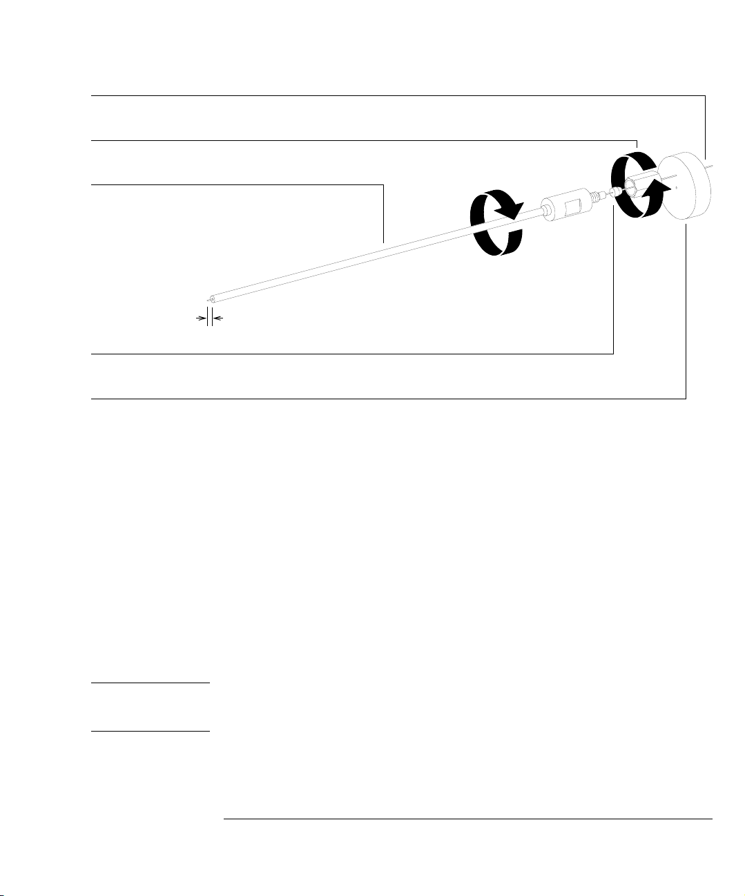
Column
Interface column nut
Column installation tool
Interface ferrule
Septum
1 Installing GC Columns
To install a capillary column using the installation tool
1 to 2 mm
CAUT ION
8 Remove the column and nut from the installation tool.
The total length from the septum to the end of the column is 176 mm.
9 Clean the outside of the end of the column with a lint-free cloth moistened
with methanol.
10 Insert the column into the GC/MSD interface.
11 Tighten the nut 1/4 to 1/2 turn.
Check tightness after one or two heat cycles.
12 Pump down the MSD.
The column installation tool must be kept clean to prevent contaminating the column and the ion source.
Keep it in its storage tube, and clean it by flushing with methanol after each use.
41
Page 42

42
Page 43

2
To view MSD analyzer temperature and vacuum status, 48
To set monitors for MSD temperature and vacuum status, 50
To set the MSD analyzer temperatures, 52
To set the GC/MSD interface temperature from the PC, 54
To monitor high vacuum pressure, 56
To measure column flow linear velocity, 58
To calculate column flow, 59
To tune the MSD, 60
To set the interface temperature from a 6890 GC, 77
To remove the MSD covers, 62
To vent t he MS D, 64
To open the analyzer chamber, 66
To close the analyzer chamber, 68
To pump down the MSD, 70
To connect the gauge controller, 73
To move or store the MSD, 75
Operating the MSD
How to perform some basic operating procedures for the MSD
Page 44

Operating the MSD
Operation of the MSD from the data system
The software performs tasks such as pumpdown, monitoring pressures,
setting temperatures, tuning, and preparing to vent. These tasks are described in this chapter. Data acquisition and data analysis are described in
the manuals and online help supplied with the MSD ChemStation software.
Operation of the MSD from the control panel
You can use the 5973 inert MSD control panel to perform many of the same
tasks that the ChemStation can perform. See the 5973N and 5973 inert
Mass Selective Detector Local Control Panel (LCP) Quick Reference
(G2589-90072) for more information.
Some conditions must be met before you turn on the MSD
Verify the following
before you turn on or attempt to operate the MSD.
• The vent valve must be closed (the knob turned all the way clockwise).
• All other vacuum seals and fittings must be in place and fastened
correctly. (The the front side plate screw should not be tightened, unless
hazardous carrier or reagent gasses are being used.
• The MSD is connected to a grounded power source.
• The GC/MSD interface extends into the GC oven.
• A conditioned capillary column is installed in the GC inlet and in the
GC/MSD interface.
• The GC is on, but the heated zones for the GC/MSD interface, the
injection port, and the oven are off.
• Carrier gas of at least 99.999% purity is plumbed to the GC with the
recommended traps.
• If hydrogen is used as carrier gas, carrier gas flow must be off, and the
front sideplate thumbscrew must be loosely fastened.
• The foreline pump exhaust is properly vented.
44
Page 45

2 Operating the MSD
WA R N I N G The exhaust from the foreline pump contains solvents and the chemicals you are analyzing.
It also contains traces of pump oil. The supplied oil trap stops only pump oil. It does not trap
or filter out toxic chemicals. If you are using toxic solvents or analyzing toxic chemicals,
remove the oil trap. Install a hose (11 mm id) to take the foreline pump exhaust outside or to
a fume (exhaust) hood.
WA R N I N G If you are using hydrogen as a carrier gas, do not start carrier gas flow until the MSD has
been pumped down. If the vacuum pumps are off, hydrogen will accumulate in the MSD and
an explosion may occur. Read the Hydrogen Carrier Gas Safety Guide (5955-5398) before
operating the MSD with hydrogen carrier gas.
The data system or control panel help you pump down the MSD
Pumpdown is mostly automated. Once you close the vent valve and turn on
the main power switch (while pressing on the sideplate), the MSD pumps
down by itself. The data system software contains a program that monitors
and displays system status during pumpdown. When the pressure is low
enough, the program turns on the ion source and mass filter heaters. It also
prompts you to turn on the GC/MSD interface heater. The 5973 inert MSD
will shutdown if it cannot pump down correctly.
Monitoring the pressure in the MSD
The data system displays the turbo pump motor speed for the turbo pump
MSDs.
Each MSD is equipped with a triode ionization gauge tube. If your MSD is
also equipped with an 59864B Gauge Controller, the triode gauge can
measure the pressure in the analyzer chamber. The high vacuum pressure
measured by the triode gauge cannot be monitored through the data system.
It is displayed on the gauge controller.
45
Page 46

2 Operating the MSD
MSD temperatures are controlled through the data system
The MSD has independent heaters and temperature sensors for the ion
source and quadrupole mass filter. You can adjust the setpoints and view
these temperatures from the data system, or from the control panel.
The GC/MSD interface heater is powered and controlled by the Thermal
Aux #2 heated zone of the 6890 Series GC. The GC/MSD interface temperature can be set and monitored from the data system or from the
GC keypad.
Column flow is controlled through the data system
Carrier gas flow through the GC column is controlled by head pressure in
the GC. For a given head pressure, the column flow will decrease as the GC
oven temperature increases. With electronic pneumatic control (EPC) set
to
Const Flow (constant flow), the same column flow is be maintained regard-
less of oven temperature.
The MSD can be used to measure actual column flow. You inject a
small
amount of air or other unretained chemical, and time how long it takes to
reach the MSD. With this time measurement, you can calculate the column
flow. See page 58..
The data system aids in venting
A program in the data system guides you through the venting process. It
switches off the GC and MSD heaters and the diffusion pump heater or turbo
pump at the correct time. It also lets you monitor temperatures in the MSD
and indicates when to vent the MSD.
The MSD
will be damaged by incorrect venting. A diffusion pump will
backstream vaporized pump fluid onto the analyzer if the MSD is vented
before the diffusion pump has fully cooled. A turbo pump will be damaged
if it is vented while spinning at more than 50% of its normal operating speed.
46
Page 47

2 Operating the MSD
.
WA R N I N G Make sure the GC/MSD interface and the analyzer zones are cool (below 100°C) before you
vent the MSD. 100°C is still hot enough to burn skin; always wear cloth gloves when
handling analyzer parts.
WA R N I N G If you are using hydrogen as a carrier gas, the carrier gas flow must be off before turning off
the MSD power. If the foreline pump is off, hydrogen will accumulate in the MSD and an
explosion may occur. Read the Hydrogen Carrier Gas Safety Guide (5955-5398) before
operating the MSD with hydrogen carrier gas.
CAUT ION
CAUT ION
CAUT ION
Never vent the MSD by allowing air in through either end of the foreline hose. Use the vent valve or
remove the column nut and column.
Do not vent or shut off the power on a diffusion pump MSD while the pump is hot.
Do not vent while the turbo pump is still spinning at more than 50%.
Do not exceed the maximum recommended total gas flow. See “5973 inert MSD models and features”
on page 18.
Moving or storing the MSD requires special care
The best way to keep your MSD functioning properly is to keep it pumped
down and hot, with carrier gas flow. If you plan to move or store your MSD,
a few additional precautions are required. The MSD must remain upright at
all times; this requires special caution when moving. The MSD should not be
left vented to atmosphere for long periods.
47
Page 48

2 Operating the MSD
To view MSD analyzer temperature and vacuum status
To view MSD analyzer temperature and vacuum status
Software changes The software is revised periodically. If the steps in this procedure do not
match your MSD ChemStation software, refer to the manuals and online help
supplied with the software for more information.
See also You can also use the Control Panel to perform this task. See the 5973N and 5973
inert Mass Selective Detector Local Control Panel (LCP) Quick Reference
Guide (G2589-90072) for more information.
1 In Instrument Control view, select Edit MS Tune Parameters from the
Instrument menu.
2 Select the tune file you plan to use with your method from the Load MS Tune
File dialog box.
3 Analyzer temperatures and vacuum status are displayed in the Zones field.
Unless you have just begun the pumpdown process, the turbo pump should be
running at least 80% speed. MSD heaters remain off as long as the turbo pump is
operating at less than 80%. Normally, the turbo pump speed will be at 100%.
The MSD heaters turn off at the beginning of the vent cycle, and turn on at the end
of the pumpdown cycle. Note that the reported setpoints will not change during
venting or pumpdown, even though both the MSD zones are turned off.
48
Page 49

2 Operating the MSD
To view MSD analyzer temperature and vacuum status
49
Page 50

2 Operating the MSD
To set monitors for MSD temperature and vacuum status
To set monitors for MSD temperature and vacuum status
Monitors display the current value of a single instrument parameter. They
can be added to the standard instrument control window. Monitors can be
set to change color if the actual parameter value varies beyond a user-determined limit from the parameter setpoint. This procedure describes how to
add monitors to your instrument control view.
Software changes The software is revised periodically. If the steps in this procedure do not
match your MSD ChemStation software, refer to the manuals and online help
supplied with the software for more information.
1 Select MS Monitors from the Instrument menu.
2 In the Edit MS Monitors box, under Type, select Zone.
3 Under Parameter, select MS Source and click Add.
4 Under Parameter, select MS Quad and click Add.
5 Under Parameter, select TurboSpd and click Add.
6 Click OK.
The new monitors will be stacked on top of each other in the lower right corner of
the Instrument Control window. They must be moved for you to see them all.
7 Click and drag each monitor to the desired position.
See the accompanying illustration for an example of arranging the monitors.
8 To make the new settings part of the method, select Save from the Method
menu.
50
Page 51

2 Operating the MSD
To set monitors for MSD temperature and vacuum status
51
Page 52

2 Operating the MSD
To set the MSD analyzer temperatures
To set the MSD analyzer temperatures
Setpoints for the MSD ion source and mass filter (quad) temperatures are stored
in the current tune (*.u) file. When a method is loaded, the setpoints in the tune
file associated with that method are downloaded automatically.
Software changes The software is revised periodically. If the steps in this procedure do not
match your MSD ChemStation software, refer to the manuals and online help
supplied with the software for more information.
1 In Instrument Control view, select Edit MS Tune Parameters from the
Instrument menu.
2 Select Temperatures from the MoreParams menu.
3 Type the desired Source and Quad (mass filter) temperatures in the
setpoint fields and click OK.
See Table 1 on page 53 for recommended setpoints
CAUT ION
The GC/MSD interface, ion source, and quadrupole heated zones interact. The
analyzer heaters may not be able to accurately control temperatures if the setpoint
for one zone is much lower than that of an adjacent zone.
Do not exceed 200°C for the quadrupole or 300°C for the source.
4 Click OK in the Edit Parameters window to apply the new temperature
setpoints.
5 When the Save MS Tune File dialog box appears, either click OK to save your
changes to the same file or type a new file name and click OK.
52
Page 53

2 Operating the MSD
To set the MSD analyzer temperatures
Table 1 Recommended temperature settings
EI operation PCI operation NCI operation
MS Source 230 250 150
MS Quad 150 150 150
53
Page 54

2 Operating the MSD
To set the GC/MSD interface temperature from the PC
To set the GC/MSD interface temperature from the PC
Software changes The software is revised periodically. If the steps in this procedure do not
match your MSD ChemStation software, refer to the manuals and online help
supplied with the software for more information.
See also You can also use the Control Panel to perform this task. See the 5973N and 5973
inert Mass Spectrometer Detector Local Control Panel (LCP) Quick Reference
(G2589-90072) for more information.
1 Select Instrument Control from the View menu.
2 Click the Aux button to display the Instrument | Edit | Aux: (6890) window.
3 Ve r ify t hat MSD is selected under Type and Thermal Aux #2 is selected under
Aux Channel.
CAUT ION
CAUT ION
4 Turn the heater on, and type the setpoint in the Next °C column. Do not set
temperature ramps.
5 The typical setpoint is 280°C.
The limits are 0°C and 350°C. A setpoint below ambient temperature turns off the
interface heater.
Never exceed the maximum temperature for your column.
6 Click Apply to download setpoints or click OK to download setpoints and
close the window.
7 To make the new settings part of the method, select Save from the Method
menu.
Make sure that the carrier gas is turned on and the column has been purged of air before heating the
GC/MSD interface or the GC oven.
54
Page 55

2 Operating the MSD
To set the GC/MSD interface temperature from the PC
55
Page 56

2 Operating the MSD
To monitor high vacuum pressure
To monitor high vacuum pressure
Materials needed: Gauge controller (59864B)
Triode ionization gauge cable (8120-6573)
WA R N I N G Never connect or disconnect the cable from the triode gauge tube while the MSD is under
vacuum. Risk of implosion and injury due to broken glass exists.
WA R N I N G If you are using hydrogen as a carrier gas, do not turn on the triode gauge tube if there is
any possibility that hydrogen has accumulated in the analyzer chamber. The triode gauge
filament can ignite hydrogen. Read the Hydrogen Carrier Gas Safety Guide (5955-5398)
before operating the MSD with hydrogen carrier gas.
1 Connect the gauge controller to the ionization gauge tube (page 73).
2 Start up and pump down the MSD (page 70).
3 Switch on the power switch on the back of the gauge controller.
4 Press and release the GAUGE button.
After a few seconds, the pressure should be displayed.
Pressure is displayed in the format X.X – X where – X is the base 10 exponent.
Units are Torr.
The gauge controller will not turn on if the pressure in the MSD is above approximately 8 × 10
triode gauge tube can measure pressures between approximately 8 × 10
than 2 × 10
-3
Torr. The gauge controller will display all 9s and then go blank. The
-6
Torr. The gauge controller is calibrated for nitrogen, but all pressures
-3
and less
listed in this manual are for helium. Refer to the manual for the 59864B for information on relative sensitivity to different gases.
The largest influence on operating pressure in EI mode is the carrier gas (column)
flow. The following table lists typical pressures for various helium carrier gas flows.
These pressures are approximate and will vary from instrument to instrument, by
as much as 30%
56
Page 57

To monitor high vacuum pressure
Table 2 Typical MSD pressure readings for various helium carrier gas flow rates
Turbo pump MSDs
2 Operating the MSD
Column flow (ml/min) Triode gauge reading (Torr),
Per for m anc e turbo pump
-
1.0 1.5 × 10
2.0 3.0 × 10
2.4 3.5 × 10
3.0 4.5 × 10
4.0 5.0 × 10
5
4.0 × 10
-
5
8.0× 10
-
5
1.0 × 10
-
5
Not supported
-
5
Not supported
Triode gauge reading (Torr),
Standard turbo pump
-
5
-
5
-
4
(Not recommended)
If the pressure is consistently higher than those listed, refer to the online help in
the MSD ChemStation software for information on troubleshooting air leaks and
other vacuum problems.
If the pressure rises above approximately 8 × 10
will turn off the triode gauge tube. The gauge tube
-3
Torr, the gauge controller
does not turn back on
automatically.
57
Page 58

2 Operating the MSD
To measure column flow linear velocity
To measure column flow linear velocity
Materials needed: Syringe
1 Set Data Acquisition for splitless manual injection and selected ion
monitoring (SIM) of m/z 28.
2 Press the Prep Run button on the GC keypad.
3 Inject 1 µl of air into the injection port and press the Start Run button.
4 Wait until a peak elutes at m/z 28.
Note the retention time.
5 Calculate the average linear velocity.
Average linear velocity (cm/sec) =
100 L
-------------t
where:
L = length of the column in meters
t = retention time in seconds
Be sure to account for any pieces of column broken off. A 1-meter section missing
from a 25-meter column can yield a 4% error.
6 Use this value to verify the MSD ChemStation flow calculations (page 59).
If the numbers disagree, click the Change button to calibrate the column dimensions.
7 To calculate the volumetric flow rate.
Volumetric flow rate (ml/min) =
0.785 D
-----------------------------
2
L
t
where:
D = internal column diameter in millimeters
L = the column length in meters
t = the retention time in minutes
58
Page 59

To calculate column flow
1 In the Instrument Control view, click the Columns icon.
2 Check that the correct column dimensions are entered.
3 Type the desired value in the pressure field.
2 Operating the MSD
To calculate column flow
4 If the Average Velocity displayed is different from that obtained on
page 58, click the Change button to calibrate the column dimensions.
59
Page 60

2 Operating the MSD
To tune the MSD
To tune the MSD
Software changes The software is revised periodically. If the steps in this procedure do not
match your MS ChemStation software, refer to the manuals and online help
supplied with the software for more information.
See also You can also use the Control Panel to run the autotune that is currently loaded in
the PC memory. See the 5973N and 5973 inert Mass Selective Detector Local
Control Panel (LCP) Quick Reference (G2589-90072) for more information.
1 In the Instrument Control View, select Perform MS Autotune from the
Instrument menu.
2 Select the tune program you wish to use.
The tune will start immediately. For most applications, Autotune gives the best
results. Standard Tune is not recommended, as it may reduce sensitivity.
Quick Tune is used to adjust peak width, mass assignment, and abundance, without
changing ion ratios. If your system is configured for chemical ionization (CI), you
will be able to access the CI Tunepanel from this box. Always tune the MSD with
the same GC oven temperature and column flow, and the same analyzer temperatures that will be used for data acquisition.
3 Wait for the tune to complete and to generate the report.
Save your tune reports. To view history of tune results, select View Tunes... under
the Qualify menu.
4 To manually tune your MSD or to perform special autotunes, select
Manual Tune from the View menu.
In the Tune and Vacuum Control viewTune and Vacuum Control view, you can
manually adjust most tune parameters to suit special needs.
From the Tune menu, in addition to the tunes available from Instrument Control,
you can select special autotunes for specific spectral results: DFTPP Tune,
BFB Tune, or Target Tune.
See the manuals or online help provided with your MSD ChemStation software for
additional information about tuning.
60
Page 61

To verify system performance
Materials needed: 1 pg/µl (0.001 ppm) OFN sample (8500-5441)
Verify the tune performance
1 Verify that the system has been pumping down for at least 60 minutes.
2 Set the GC oven temperature to 150°C, and the column flow to 1.0 ml/min.
3 In the Instrument Control view, select Checkout Tune from the Qualify menu.
The software will perform an autotune and print out the report.
4 When the autotune has completed, save the method, and then select Tune
Evaluation from the Qualify menu.
The software will evaluate the last autotune and print a System Verification – Tune
report.
2 Operating the MSD
To verify system performance
Verify the sensitivity performance
1 Set up to inject 1 µl of OFN, either with the ALS or manually.
2 In the Instrument Control view, select Sensitivity Check from the Qualify
menu.
3 Click the appropriate icons in the Instrument | Edit window to edit the
method for the type of injection.
4 Click OK to run the method.
When the method is completed, an evaluation report will print out.
Verify that rms signal-to-noise ratio meets the published specification. See the
5973N and 5973 inert Mass Selective Detector Local Control Panel (LCP)
Quick Reference (G2589-90072).
61
Page 62

2 Operating the MSD
To remove the MSD covers
To remove the MSD covers
Materials needed: Screwdriver, TORX T-15 (8710-1622)
The analyzer cover is removed for venting and for many maintenance procedures.
The lower MSD cover is removed to check the fluid level in the diffusion pump and
for a few maintenance procedures. If you need to remove one of the MSD covers,
follow these procedures:
Analyzer cover
1 Grasp the front of the analyzer cover and lift up enough to unlatch the five
front tabs.
2 Reach back and grasp the back edge of the analyzer cover.
3 Pull forward to disengage the rear spring latch.
It may take a firm pull to disengage the latch.
To reinstall the analyzer cover, reverse these steps.
Lower MSD cover
1 Remove the analyzer cover.
2 Remove the 3 screws that hold the lower MSD cover in place.
3 Pull the cover left slightly to disengage the two right side tabs and then
pull it straight forward.
To reinstall the lower MSD cover, reverse these steps.
WA R N I N G Do not remove any covers other than the upper and lower MSD covers. Dangerous voltages
are present under other covers.
62
Page 63

Analyzer cover
Latch tabs
Lower cover
2 Operating the MSD
To remove the MSD covers
Slots for tabs
CAUT ION
Do not use excessive force, or the plastic tabs that hold the cover to the mainframe will break off.
63
Page 64

2 Operating the MSD
To vent the MSD
To vent the MSD
Firmware changes The firmware is revised periodically. If the steps in this procedure do not
match your MSD control panel, refer to the manuals and online help supplied
with the software, or the 5973N and 5973 inert Mass Selective Detector Local
Control Panel (LCP) Quick Reference (G2589-90072) for more information.
1 If your system is equipped with a gauge controller, switch off the triode
gauge controller.
2 Before venting a CI MSD, press the Gas Off button (turns off the reagent
gas flow and closes the isolation valve.)
WAR N ING On a CI MSD, the Gas Off light must be on when the MSD is venting.
3 Select Ve n t from the from the Vacuum menu in the software. Follow the
instructions presented.
4 Set the GC/MSD interface heater and the GC oven temperatures to
ambient (25°C).
WA R N I N G If you are using hydrogen as a carrier gas, the carrier gas flow must be off before turning off
the MSD power. If the foreline pump is off, hydrogen will accumulate in the MSD and an
explosion may occur. Read the Hydrogen Carrier Gas Safety Guide (5955-5398) before
operating the MSD with hydrogen carrier gas.
CAUT ION
WAR N ING
Be sure the GC oven and the GC/MSD interface are cool before turning off carrier gas flow.
5 When prompted, turn off the MSD power switch.
6 Unplug the MSD power cord.
When the MSD is vented, do not put the ChemStation into Top view. Doing so will turn on the
interface heater.
7 Remove the analyzer cover (page 62).
64
Page 65

YES NO
2 Operating the MSD
To vent the MSD
8 Turn the vent valve knob counterclockwise only 3/4 turns or until you hear
the hissing sound of air flowing into the analyzer chamber.
Do not turn the knob too far, or the O-ring may fall out of its groove. Be sure to
retighten the knob before pumping down.
WA R N I N G Allow the analyzer to cool to near room temperature before touching it.
CAUT ION
WAR N ING
Always wear clean gloves while handling any parts that go inside the analyzer chamber.
When the MSD is vented, do not put the ChemStation into Top view. Doing so will turn on the
interface heater.
65
Page 66

2 Operating the MSD
To open the analyzer chamber
To open the analyzer chamber
Materials needed: Gloves, clean, lint-free
large (8650-0030)
small (8650-0029)
Wrist strap, anti-static
small (9300-0969)
medium (9300-1257)
large (9300-0970)
CAUT ION
Electrostatic discharges to analyzer components are conducted to the side board where they can damage
sensitive components. Wear a grounded anti-static wrist strap and take other anti-static precautions (see
page 168) before you open the analyzer chamber.
1 Ve n t th e MSD (page 64).
2 Disconnect the side board control cable and the source power cable from
the side board.
3 Loosen the side plate thumbscrews, if they are fastened.
The rear side plate thumbscrew should be unfastened during normal use. It is only
fastened during shipping. The front side plate thumbscrew should only be fastened for CI operation or if hydrogen or other flammable or toxic substances are
used for carrier gas.
4 Gently swing the side plate out.
WA R N I N G The analyzer, GC/MSD interface, and other components in the analyzer chamber operate at
very high temperatures. Do not touch any part until you are sure it is cool.
CAUT ION
Always wear clean gloves to prevent contamination when working in the analyzer chamber.
CAUT ION
If you feel resistance, stop. Do not try to force the side plate open. Verify that MSD is vented. Verify that
both the front and rear side plate screws are completely loose.
66
Page 67

Front thumbscrew
Rear thumbscrew –
do not tighten
Source power cable
Side board control cable
Side plate
2 Operating the MSD
To open the analyzer chamber
67
Page 68

2 Operating the MSD
To close the analyzer chamber
To close the analyzer chamber
Materials needed: Gloves, clean, lint-free
large (8650-0030)
small (8650-0029)
1 Make sure all the internal analyzer electrical leads are correctly attached.
2 Check the side plate O-ring.
Make sure the O-ring has a very light coat of Apiezon L high vacuum grease. If the
O-ring is very dry, it may not seal well. If the O-ring looks shiny, it has too much
grease on it. See page 197 for instructions for lubricating the side plate O-ring.
3 Close the side plate.
4 Reconnect the side board control cable and source power cable to the side
board.
5 Make sure the vent valve is closed.
6 Pump down the MSD (page 70).
7 Gently hand tighten the front side plate thumbscrew.
This is only necessary for CI MSDs, or if hydrogen or other flammable or toxic substance is used for carrier gas.
WA R N I N G This thumbscrew must be fastened for CI operation or if hydrogen (or other hazardous gas)
is being used as the GC carrier gas. In the unlikely event of an explosion, it may prevent the
side plate from opening.
CAUT ION
Do not overtighten the thumbscrew; it can cause air leaks or prevent successful pumpdown. Do not use
a screwdriver to tighten the thumbscrew.
8 Once the MSD has pumped down, reinstall the analyzer cover.
Wait until after pumpdown to reinstall the analyzer cover.
68
Page 69

Front thumbscrew
Rear thumbscrew –
do not tighten
Source power cable
Side board control cable
Side plate
2 Operating the MSD
To close the analyzer chamber
69
Page 70

2 Operating the MSD
To pump down the MSD
To pump down the MSD
Software changes The software is revised periodically. If the steps in this procedure do not match
your MSD ChemStation software, refer to the manuals and online help supplied
with the software for more information.
See also You can also use the Control Panel to perform this task. See the 5973N and 5973
inert Mass Selective Detector Local Control Panel (LCP) Quick Reference
(G2589-90072) for more information.
WA R N I N G Make sure your MSD meets all the conditions listed in the introduction to this chapter (page
44) before starting up and pumping down the MSD. Failure to do so can result in personal
injury.
WA R N I N G If you are using hydrogen as a carrier gas, do not start carrier gas flow until the MSD has
been pumped down. If the vacuum pumps are off, hydrogen will accumulate in the MSD and
an explosion may occur. Read the Hydrogen Carrier Gas Safety Guide (5955-5398) before
operating the MSD with hydrogen carrier gas.
1 Plug in the MSD power cord.
2 Select Diagnostics/Vacuum Control from the View menu.
Select Pump Down from the Vacuum menu.
3 When prompted, switch on the MSD
4 Press lightly on the side board to ensure a correct seal.
Press on the metal box on the side board.
The rough pump will make a gurgling noise. This noise should stop within a minute.
If the noise continues, there is a
plate seal, the interface column nut, or the vent valve.
5 Once communication with the PC has been established, click OK.
70
large air leak in your system, probably at the side
Page 71

2 Operating the MSD
To pump down the MSD
CAUT ION
CAUT ION
Within 10 to 15 minutes the turbo pump speed should be up to 80%. The turbo pump speed should
eventually reach 95%. If these conditions are not met, the MSD electronics will shut off the foreline
pump. In order to recover from this condition, you must power cycle the MSD. If the MSD does not pump
down correctly, see the manual or online help for information on troubleshooting air leaks and other
vacuum problems.
6 When prompted, turn on the GC/MSD interface heater and GC oven. Click
OK when you have done so.
The software will turn on the ion source and mass filter (quad) heaters. The temperature setpoints are stored in the current autotune (*.u) file.
Do not turn on any GC heated zones until carrier gas flow is on. Heating a column with no carrier gas
flow will damage the column.
7 After the message Okay to run appears, wait two hours for the MSD to reach
thermal equilibrium.
Data acquired before the MSD has reached thermal equilibrium may not be
reproducible.
8 Reinstall the MSD top cover.
The top cover was removed during the vent procedure.
71
Page 72

2 Operating the MSD
To pump down the CI MSD
To pump down the CI MSD
Software changes The software is revised periodically. If the steps in this procedure do not match your
MSD ChemStation software, refer to the manuals and online help supplied with the
software for more information.
See also You can also use the Control Panel to perform this task. See the 5973N and 5973
inert Mass Selective Detector Local Control Panel (LCP) Quick Reference
(G2589-90072) for more information.
1 Follow the instructions in the previous module.
See “To pump down the MSD” on page 70.
After the software prompts you to turn on the interface heater and GC oven,
perform the following steps.
2 Check vacuum gauge controller to verify that the pressure is decreasing.
3 Press Gas A and Purge, and verify that the Gas A and Purge lights are on.
4 Ve r ify t hat PCICH4.U is loaded, and accept the temperature setpoints.
Always start up, and verify system performance in PCI mode before switching to
NCI.
5 Set the GC/MSD interface to 320°C.
6 Purge for at least one hour.
7 Press the Purge button to turn off Purge.
8 Set Gas A to 20%.
9 Let system bake out and purge for at least two hours. If you will be running
NCI, best sensitivity, bake the MSD out overnight.
72
Page 73

2 Operating the MSD
To connect the gauge controller
To connect the gauge controller
Materials needed: Gauge controller (59864B)
Power cord
Triode gauge cable (8120-6573)
The high-vacuum gauge controller is required for operating the MSD in CI mode.
WA R N I N G Never connect or disconnect the cable from the triode gauge tube while the MSD is under
vacuum. Risk of implosion and injury due to broken glass exists.
CAUT ION
CAUT ION
Be sure to orient the cable and the gauge tube as illustrated. Excessive force on the pins can break the
tube. Do not stress the cable.
1 Connect the triode gauge cable to the triode gauge tube.
2 Connect the other end of the triode gauge cable to the gauge controller.
3 Connect the power cord to the gauge controller.
4 Connect the other end of the power cord to an appropriate electrical
outlet.
If you wish to share one controller among MSDs, obtain one cable for each instrument. Leave a cable connected to the triode gauge tube on each MSD. This will
avoid having to vent the MSD before connecting the controller.
5 Pump down the MSD.
Do not use a 59864A (older model) triode gauge controller during data acquisition. This model can be
used for diagnostic purposes
only.
73
Page 74

Triode gauge tube
Triode gauge cable
2 Operating the MSD
To connect the gauge controller
Gauge controller
Triode gauge cable
Power cord
74
Page 75

To move or store the MSD
Materials needed: Ferrule, blank (5181-3308)
Interface column nut (05988-20066)
Wrench, open-end, 1/4-inch × 5/16-inch (8710-0510)
1 Ve n t th e MSD (page 64).
2 Remove the column and install a blank ferrule and interface nut.
3 Tighten the vent valve.
4 If the MSD has a gauge controller, disconnect the cable from the triode
gauge tube.
5 Move the MSD away from the GC (page 178).
Unplug the GC/MSD interface heater cable from the GC.
2 Operating the MSD
To move or store the MSD
CAUT ION
6 Install the interface nut with the blank ferrule.
7 Remove the analyzer cover (page 62).
8 Tighten the side plate thumbscrews to “finger tight”.
Do not overtighten the side plate thumbscrews. Overtightening will strip the threads in the analyzer
chamber. It will also warp the side plate and cause leaks.
9 Plug the MSD power cord in.
10 Switch the MSD on to establish a rough vacuum.
Verify that the turbo pump speed is greater than 50%.
11 Switch the MSD off.
12 Reinstall the analyzer cover.
13 Disconnect the LAN, remote, and power cables.
75
Page 76

Front side plate thumbscrew
Rear side plate thumbscrew
2 Operating the MSD
To move or store the MSD
CAUT ION
The MSD can now be stored or moved. The foreline pump cannot be disconnected.
It must be moved with the MSD. Make sure the MSD remains upright and is never
tipped on its side or inverted.
The MSD must remain upright at all times. If you need to ship your MSD to another location, contact
your Agilent Technologies service representative for advice about packing and shipping.
76
Page 77

2 Operating the MSD
To set the interface temperature from a 6890 GC
To set the interface temperature from a 6890 GC
1 Press the Aux # key on the GC keypad.
2 Press 2.
By default, the GC/MSD interface is powered by heated zone Thermal Aux #2 on
the 6890 Series GC. Verify that the display shows THERMAL AUX 2 (MSD).
3 Use the number keys to type in the new temperature setpoint.
The typical setpoint is 280°C. The limits are 0°C and 350°C. A setpoint below
ambient temperature turns off the interface heater.
CAUT ION
CAUT ION
Never exceed the maximum temperature of your column.
Make sure that the carrier gas is turned on and the column has been purged of air before heating the
GC/MSD interface or the GC oven.
4 Press the Enter key to download the new setpoint.
If you want the new setpoint to become part of the current method, click Save
under the Method menu. Otherwise, the first time a method is loaded, all the setpoints in the method will overwrite those set from the GC keyboard.
77
Page 78

2 Operating the MSD
To set the interface temperature from a 6890 GC
78
Page 79

3
To operate the CI MSD, 80
To switch from EI to CI operating mode, 82
To set up the software for CI operation, 83
To set up methane reagent gas flow, 86
CI autotune, 88
To perform a positive CI autotune (methane only), 90
To perform a negative CI autotune (any reagent gas), 92
To verify positive CI performance, 94
To verify negative CI performance, 95
To operate the reagent gas flow control module, 84
To monitor high vacuum pressure, 96
To use other reagent gases, 98
To switch from CI to EI operating mode, 102
Operating the CI MSD
Page 80

Operating the MSD in CI mode
This chapter provides information and instructions about operating the
5973 inert CI MSDs in CI mode. Most of the material is related to methane
chemical ionization but one section discusses the use of other reagent gases.
NOTE
Sequencing is not appropriate for automating methods that use different reagent gases or gas flows, as
these parameters must be set
manually.
The software provides instructions for setting the reagent gas flow and for
performing CI autotunes. Autotunes are provided for PCI with methane
reagent gas and for NCI with any reagent gas.
General guidelines
• Always use the highest purity methane (and other reagent gases, if
applicable.) Methane must be at least 99.99% pure.
• Always verify that the MSD is performing well in EI mode before
switching to CI. See “To verify system performance” on page 61.
• Make sure the CI ion source and GC/MSD interface tip seal are installed.
• Make sure the reagent gas plumbing has no air leaks. This is determined
in PCI mode, checking for m/z 32 after the methane pre-tune.
To operate the CI MSD
Operating your MSD in the CI mode is slightly more complicated than
operating in the EI mode. After tuning, gas flow, source temperature
(Table 3 on page 80), and electron energy may need to be optimized for your
specific analyte.
Table 3 Temperatures for CI operation
Ion source Quadrupole GC/MSD interface
PCI 250°C 150°C 320°C
NCI 150°C 150°C 280°C
Page 81

3 Operating the CI MSD
Start the system in PCI mode first.
By bringing the system up in PCI mode first, you will be able to do the
following:
• Set up the MSD with methane first, even if you are going to use another
reagent gas.
• Check the interface tip seal by looking at the m/z 28 to 27 ratio (in the
methane flow adjust panel.).
• Tell if a gross air leak is present by monitoring the ions at m/z 19
(protonated water) and 32.
• Confirm if the MS is generating “real” ions and not just background noise.
It is nearly impossible to perform any diagnostics on the system in NCI. In
NCI, there are no reagent gas ions to monitor for any gas. It is difficult to
diagnose an air leak and difficult to tell whether a good seal is being created
between the interface and the ion volume.
81
Page 82

3 Operating the CI MSD
To switch from EI to CI operating mode
To switch from EI to CI operating mode
CAUT ION
CAUT ION
Always verify MSD performance in EI before switching to CI operation. See page 51. Always set up the
CI MSD in PCI first, even if you are going to run NCI
1 Vent the MSD. See page 64.
2 Open the analyzer.
3 Remove the EI ion source.
Electrostatic discharges to analyzer components are conducted to the side board where they can damage
sensitive components. Wear a grounded anti-static wrist strap
See “Electrostatic discharge is a threat to the MSD electronics during maintenance” on page 168. Take
anti-static precautions
4 Install the CI ion source. See page 246.
5 Install the interface tip seal. See page 248.
6 Close the analyzer.
7 Pump down the MSD. See page 70.
before you open the analyzer chamber.
82
Page 83

3 Operating the CI MSD
To set up the software for CI operation
To set up the software for CI operation
1 Switch to the Tune and Vacuum Control view.
2 Select Load Tune Values from the File menu.
3 Select the tune file PCICH4.U.
4 If CI autotune has never been run for this tune file, the software will
prompt you through a series of dialog boxes. Accept the default values
unless you have a very good reason for changing anything.
The tune values have a dramatic effect on MSD performance. Always start with the
default values when first setting up for CI, and then make adjustments for your
specific application. See the table below for default values for the Tune Control
Limits box.
Default Tune Control Limits, used by CI autotune only. These limits should not be confused with the parameters set in Edit
MS Parameters, or with those appearing on the tune report.
Reagent gas Methane Isobutane
1x10
a
6
Ion polarity Positive Negative
Abundance targetb,1x10
Peakwidth target
d
6
0.6 0.6 N/A
Maximum repeller 4 4 N/A
Maximum emission current
e
, µA 240 50 N/A
Max electron energy, eV 240 240 N/A
Positive
c
N/A
c
c
c
c
a
a
a
Negative
6
1x10
0.6 N/A
Positive
c
N/A
c
Ammonia
a
4N/Ac4
50 N/A
240 N/A
c
c
a. Always set up in PCI with methane first, then switch to your desired ion polarity and reagent gas.
b. Adjust higher or lower to get desired signal abundance. Higher signal abundance also gives higher noise
abundance. This is adjusted for data acquisition by setting the EMV in the method.
c. There are no PFDTD ions formed in PCI with any reagent gas but methane, hence, CI autotune is not available with these config-
urations.
d. Higher peakwidth values give better sensitivity, lower values give better resolution.
e. Optimum emission current maximum for NCI is very compound-specific, and must be selected empirically. Optimum emission
current for pesticides, for example, may be about 200 µA.
a
Negative
6
1x10
0.6
50
240
a
83
Page 84

3 Operating the CI MSD
To operate the reagent gas flow control module
To operate the reagent gas flow control module
For a video demonstration of the gas flow control module, see the
5973 inert MSD Manual CD-ROM.
Flow control module state diagram:
Result Gas A flows Gas B flows Purge
with Gas A
Control panel lights (LEDs)
Gas A (green) On Off On Off Off Off
Gas B (amber) Off On Off On Off Off
Purge (red) Off Off On On On Off
Gas Off (red) Off Off Off Off On On
Valve state
Valve A Open Closed Open Closed Closed Closed
Valve B Closed Open Closed Open Closed Closed
MFC setting On → setpoint On → setpoint On → 100% On → 100% On → 100% Off (→0%)
Isolation valve Open Open Open Open Open Closed
Purge
with Gas B
Pump out
flow module
Standby, vented, or
EI mode
84
Page 85

Flow control knob (mass flow control knob)
Flow control display
3 Operating the CI MSD
To operate the reagent gas flow control module
85
Page 86

3 Operating the CI MSD
To set up methane reagent gas flow
To se t up methane reagent gas flow
The reagent gas flow must be adjusted for maximum stability before tuning the CI
system. Do the initial setup with methane in positive ion mode (PCI). No flow
adjustment procedure is available for NCI, as no negative reagent ions are formed.
Adjusting the methane reagent gas flow is a three-step process: setting the flow
control, pre-tuning on the reagent gas ions, and adjusting the flow for stable
reagent ion ratios, for methane, m/z 28/27.
Your data system will prompt you through the flow adjustment procedure.
CAUT ION
After the system has been switched from EI to CI mode, or vented for any other reason, the MSD must
be baked out for at least 2 hours before tuning.
1 Press the Gas A button. Verify that only the Gas A light is on.
2 Adjust the flow to 20% for PCI/NCI MSDs.
3 Check the vacuum gauge controller to verify correct pressure. See page 96.
4 Select Methane Pretune from the Setup menu.
The methane pretune tunes the instrument for optimum monitoring of the ratio of
methane reagent ions m/z 28/27.
5 Examine the displayed profile scan of the reagent ions.
• Make sure there is no visible peak at m/z 32. A peak there indicates an air leak.
If such a peak is present, find and repair the leak before proceeding. Operating
in the CI mode with an air leak will rapidly contaminate the ion source.
• Make sure that the peak at m/z 19 (protonated water) is less than 50% of the
peak at m/z 17.
6 Perform the Methane Flow Adjust.
Adjust the methane flow on the PCI/NCI MSD to get the ratio of
between 1.5 and 5.0.
m/z 28/27
86
Page 87

3 Operating the CI MSD
To set up methane reagent gas flow
CAUT ION
Continuing with CI autotune if the MSD has an air leak or large amounts of water will result in severe
ion source contamination. If this happens, you will need to
vent the MSD and clean the ion source.
Methane pre-tune after more than a day of baking out. Note the low abundance of m/z 19 and absence of any
visible peak at m/z 32. Your MSD will probably show more water at first, but the abundance of m/z 19 should still
be less than 50% of m/z 17.
87
Page 88

3 Operating the CI MSD
CI autotune
CI autotune
After the reagent gas flow is adjusted, the lenses and electronics of the MSD
should be tuned. Perfluoro-5,8-dimethyl-3,6,9-trioxidodecane (PFDTD) is used as
the calibrant. Instead of flooding the entire vacuum chamber, the PFDTD is introduced directly into the ionization chamber through the GC/MSD interface by
means of the gas flow control module.
CAUT ION
CAUT ION
After the system has been switched from EI to CI mode, or vented for any other reason, the MSD must
be purged and baked out for at least 2 hours before tuning. Longer bakeout is recommended before
running samples requiring optimal sensitivity.
There is a PCI autotune for methane only, as there are no PFDTD ions produced
by other gases in positive mode. PFDTD ions are visible in NCI for any reagent gas.
Always tune for methane PCI first regardless of which mode or reagent gas you
wish to use for your analysis.
There are no tune performance criteria. If CI autotune completes, it passes.
EMVolts (electron multiplier voltage) at or above 2600 V, however, indicates a
problem. If your method requires EMVolts set at +400, you may not have adequate
sensitivity in your data acquisition.
Always verify MSD performance in EI before switching to CI operation. See page 51. Always set up the
CI MSD in PCI first, even if you are going to run NCI
88
Page 89

3 Operating the CI MSD
CI autotune
Reagent gas Methane Isobutane Ammonia EI
Ion polarity Positive Negative Positive Negative Positive Negative N/A
Emission 150 µA
Electron energy 150 eV
Filament 1
Repeller 3 V
Ion focus 130 V
Entrance lens offset 20 V
EMVolts 1200
Gas Off Off
Gas select valve A
Suggested flow 20%
Source temp 250°C
Quad temp 150°C
Interface temp 320°C
Autotune Yes
50 µA 150 µA 50 µA 150 µA 50 µA 35 µA
150 eV 150 eV 150 eV 150 eV 150 eV 70 eV
111111 or 2
3 V 3 V 3 V 3 V 3 V 30 V
130 V 130 V 130 V 130 V 130 V 90 V
20 V 20 V 20 V 20 V 20 V 25 V
1200 1200 1200 1200 1200 1200
Off Off Off Off Off On
ABBBBNone
40% 20% 40% 20% 40% N/A
150°C 250°C 150°C 250°C 150°C 230°C
150°C 150°C 150°C 150°C 150°C 150°C
280°C 320°C 280°C 320°C 280°C 280°C
Ye s N o Ye s N o Ye s Ye s
89
Page 90

3 Operating the CI MSD
To perform a positive CI autotune (methane only)
To perform a positive CI autotune (methane only)
CAUT ION
CAUT ION
Always verify MSD performance in EI before switching to CI operation. See page 51. Always set up the
CI MSD in PCI first, even if you are going to run NCI
1 Verify that the MSD performs correctly in EI mode first. See page 61.
2 Load the PCICH4.U tune file (or an existing tune file for the reagent gas you
are using).
If you use an existing tune file, be sure to save it with a new name if you don’t want
to over write the existing values.
3 Accept the default settings.
4 Perform methane setup. See page 86.
5 Under the Tune menu, click CI Autotune.
Avoid tuning more often than is absolutely necessary; this will minimize PFDTD background noise, and
help prevent ion source contamination.
There are no tune performance criteria. If autotune completes, it passes. If the
tune sets the electron multiplier voltage (EMVolts) at or above 2600 V, however,
you may not be able to acquire data successfully if your method sets EMVolts to
“+400” or higher.
The autotune report contains information about air and water in the system.
The 19/29 ratio shows the abundance of water.
The 32/29 ratio shows the abundance of oxygen.
90
Page 91

3 Operating the CI MSD
To perform a positive CI autotune (methane only)
91
Page 92

3 Operating the CI MSD
To perform a negative CI autotune (any reagent gas)
To perform a negative CI autotune (any reagent gas)
CAUT ION
CAUT ION
Always verify MSD performance in EI before switching to CI operation. See page 51. Always set up the
CI MSD in PCI first, with methane as the reagent gas first, even if you are going to be using a different
reagent gas or going to run NCI.
1 Load NCICH4.U (or an existing tune file for the reagent gas you are using).
If you use an existing tune file, be sure to save it with a new name if you don’t want
to over write the existing values.
2 Accept the default temperature and other settings.
3 If you don’t already have an NCI tune file for your reagent gas, use
Select Reagent Gas under the Setup menu.
4 Under the Tune menu, click CI Autotune.
Avoid tuning unless absolutely necessary; this will minimize PFDTD background noise, and help prevent
ion source contamination.
There are no tune performance criteria. If autotune completes, it passes. If the
tune sets the electron multiplier voltage (EMVolts) at or above 2600 V, however,
you may not be able to acquire data successfully if your method sets EMVolts to
“+400” or higher.
92
Page 93

3 Operating the CI MSD
To perform a negative CI autotune (any reagent gas)
93
Page 94

3 Operating the CI MSD
To verify positive CI performance
To verify positive CI performance
Materials needed: Benzophenone, 100 pg/µL (8500-5440)
CAUT ION
Always verify MSD performance in EI before switching to CI operation. See page 51. Always set up the
CI MSD in PCI first, even if you are going to run NCI.
1 Verify that the MSD performs correctly in E1 and PCI mode.
2 Verify that the PCICH4.U tune file is loaded.
3 On the flow control panel, turn Purge off. Set Gas A to 20% flow.
4 In Tune and Vacuum Control view, perform CI setup. See page 88.
5 Run CI Autotune. See page 88.
6 Run the PCI sensitivity method: BENZ_PCI.M, using 1 µL of 100 pg/µL
Benzophenone.
7 Verify that the system conforms to the published sensitivity specification.
See also 5973N and 5973 inert Mass Selective Detector Specifications (5988-9991EN)
94
Page 95

To verify negative CI performance
This procedure is for EI/PCI/NCI MSDs only
Materials needed: OFN, 1 pg/µL (8500-5441)
3 Operating the CI MSD
To verify negative CI performance
CAUT ION
Always verify MSD performance in EI before switching to CI operation. See page 51. Always set up the
CI MSD in PCI first, even if you are going to run NCI
1 Verify that the MSD performs correctly in EI mode.
2 Load the NCICH4.U tune file, and accept the temperature setpoints.
3 Turn Purge and Gas A on and let the system stabilize for 90 minutes.
4 Turn Purge off, and set Gas A to 40% flow.
5 In Tune and Vacuum Control view, run CI Autotune. See page 95.
Note that there are no criteria for a “passing” Autotune in CI. If the Autotune completes, it passes.
6 Run the NCI sensitivity method: OFN_NCI.M using 1 µL of 1 pg/µL OFN.
7 Verify that the system conforms to the published sensitivity specification.
See also 5973N and 5973 inert Mass Selective Detector Specifications
(5988-9991EN)
95
Page 96

3 Operating the CI MSD
To monitor high vacuum pressure
To monitor high vacuum pressure
Materials needed: Gauge controller (59864B)
Triode gauge cable (8120-6573)
WA R N I N G Never connect or disconnect the cable from the triode gauge tube while the MSD is under
vacuum. Risk of implosion and injury due to broken glass exists.
WA R N I N G If you are using hydrogen as a carrier gas, do not turn on the triode gauge tube if there is
any possibility that hydrogen has accumulated in the manifold. The triode gauge filament
can ignite hydrogen. Read the Hydrogen Carrier Gas Safety Guide (5955-5398) before
operating the MSD with hydrogen carrier gas.
1 Connect the gauge controller to the triode gauge tube. See page 73.
2 Start up and pump down the MSD. See page 70.
3 Switch on the power switch on the back of the gauge controller.
4 Press and release the
GAUGE button.
After a few seconds, the pressure should be displayed.
Pressure is displayed in the format X.X – X where – X is the base 10 exponent.
Units are Torr.
The gauge controller will not turn on if the pressure in the MSD is above approximately 8 × 10
triode gauge tube can measure pressures between approximately 8 × 10
-6
3 × 10
-3
Torr. The gauge controller will display all 9s and then go blank. The
-3
Torr. The gauge controller is calibrated for nitrogen, but all pressures listed
in this manual are for helium.
The largest influence on operating pressure is the carrier gas (column) flow. The
following table lists typical pressures for various helium carrier gas flows. These
pressures are approximate and will vary from instrument to instrument.
and
96
Page 97

3 Operating the CI MSD
To monitor high vacuum pressure
Typical pressure readings
Use the 59864B high-vacuum gauge controller. Note that the mass flow controller
is calibrated for methane, and the high vacuum gauge controller is calibrated for
nitrogen, so these measurements are not accurate, but are intended as a guide to
typical observed readings. They were taken with the following set of conditions.
Note that these are typical PCI temperatures:
Source temperature 250°C
Quad temperature 150°C
Interface temperature 320°C
Helium carrier gas flow 1 mL/min
MFC (%) Pressure (Torr)
Methane Ammonia
EI/PCI/NCI MSD
(Performance turbo
pump)
10 5 . 5 × 10
15 8.0 × 10
20 1.0 × 10
25 1.2 × 10
30 1.5 × 10
35 2.0 × 10
40 2.5 × 10
EI/PCI/NCI MSD
(Performance turbo
pump)
–5
–5
–4
–4
–4
–4
–4
5.0 × 10
7.0 × 10
8.5 × 10
1.0 × 10
1.2 × 10
1.5 × 10
2.0 × 10
–5
–5
–5
–4
–4
–4
–4
Familiarize yourself with the measurements on your system under operating conditions, and watch for changes that may indicate a vacuum or gas flow problem.
Measurements will vary by as much as 30% from one MSD and gauge controller to
the next.
97
Page 98

3 Operating the CI MSD
To use other reagent gases
To use other reagent gases
This section describes the use of isobutane or ammonia as the reagent gas. You
should be familiar with operating the CI-equipped 5973 inert MSD with methane
reagent gas before attempting to use other reagent gases.
CAUT ION
CAUT ION
Do not use nitrous oxide as a reagent gas. It radically shortens the life span of the filament.
Changing the reagent gas from methane to either isobutane or ammonia changes
the chemistry of the ionization process and yields different ions. The principal
chemical ionization reactions encountered are described in general in Appendix A,
Chemical Ionization Theory. If you are not experienced with chemical ionization, we suggest reviewing that material before you proceed.
Not all setup operations can be performed in all modes with all reagent gases. See the following table
for details.
98
Page 99

3 Operating the CI MSD
To use other reagent gases
Reagent gas/ mode Reagent ion
masses
PFDTD
Calibrant ions
Flow adj ions: Ratio
EI/PCI/NCI MSD
Performance turbo pump
Recommended flow: 20%
Methane/ PCI 17, 29, 41
Methane/ NCI 17, 35, 235
a
b
41, 267, 599 28/27: 1.5 – 5.0
185, 351, 449 N/A
Isobutane/ PCI 39, 43, 57 N/A 57/43: 5.0 – 30.0
Isobutane/ NCI 17, 35, 235 185, 351, 449 N/A
Ammonia/ PCI 18, 35, 52 N/A 35/18: 0.1 – 1.0
Ammonia/ NCI 17, 35, 235 185, 351, 517 N/A
a. There are no PFDTD ions formed with any reagent gas but methane. Tune with methane
and use the same parameters for the other gas.
b. There are no negative reagent gas ions formed. To pretune in negative mode, use back-
ground ions:
-
17 (OH
), 35 (Cl-), and 235 (ReO
-
). These ions can not be used for reagent gas flow
3
adjustment. Set flow to 40% for NCI and adjust as necessary to get acceptable results for
your application.
Isobutane CI
Isobutane (C4H10) is commonly used for chemical ionization when less fragmentation is desired in the chemical ionization spectrum. This is because the proton
affinity of isobutane is higher than that of methane; hence, less energy is transferred in the ionization reaction. Addition and proton transfer are the ionization
mechanisms most often associated with isobutane. The sample itself influences
which mechanism dominates.
99
Page 100

3 Operating the CI MSD
To use other reagent gases
Ammonia CI
Ammonia (NH3) is commonly used for chemical ionization when less fragmentation is desired in the chemical ionization spectrum. This is because the proton
affinity of ammonia is higher than that of methane; hence, less energy is transferred in the ionization reaction. Because many compounds of interest have insufficient proton affinities, ammonia chemical-ionization spectra often result from the
addition of NH
Ammonia reagent ion spectra have principal ions at m/z 18, 35, and 52, corresponding to NH
To adjust your MSD for isobutane or ammonia chemical ionization, use the following procedure:
1 Perform a standard Positive CI autotune with methane and PFDTD.
2 Under the Setup menu, click Select Reagent Gas and select Isobutane or Ammonia.
This will change the menus to use the selected gas, and select appropriate default
tune parameters.
3 Select a new tune file name, or load an existing PCI tune file for the
specific gas.
If you use an existing tune file, be sure to save it with a new name if you don’t want
to over write the existing values. Accept the default temperature and other settings.
+
and then, in some cases, from the subsequent loss of water.
4
+
, NH4(NH3)+, and NH4(NH3)
4
+
.
2
NOTE
4 Turn Gas B on.
After the amber light stops flashing and the Purge light goes off, set the gas flow to
20%.
5 Click Isobutane (or Ammonia) Flow Adjust on the Setup menu.
There is no CI autotune for isobutane or ammonia in PCI.
If you wish to run NCI with isobutane or ammonia, load NCICH4.U, or load an
existing NCI tune file for the specific gas.
Be sure to read the following application note: Implementation of Ammonia Reagent Gas For Chemical
Ionization On 5973 MSDs (5968-7844).
100
 Loading...