

Page 1

58503B
GPS Time and Frequency
Reference Receiver
097-58503-13
Issue 2: Jul 00
and
59551A
GPS Measurements
Synchronization Module
Operating and Programming
Guide
Copyright © 2000 Symmetricom, Inc. All rights reserved. Printed in U.S.A.
Page 2

This guide describes how to operate the Symmetricom 58503B GPS Time and Frequency Reference Receiver and 59551A GPS Measurements
Synchronization Module via the RS-232C port(s).
The information in this guide applies to instruments
having the number prefix listed below, unless accompanied by a “Manual Updating Changes” package indicating otherwise.
SERIAL PREFIX NUMBER:3805A and above
(58503B), 3805A and above (59551A)
Warning Symbols That May Be Used In This Book
Instruction manual symbol; the product will be marked with this
symbol when it is necessary for the user to refer to the
instruction manual.
Instruments with serial numbers below 3805A may
have earlier versions of firmware installed. There
are no operator-specific differences in previous versions of firmware.
FIRMWARE REVISION:3805A and above
(58503B), 3805A and above (59551A)
Firmware revision can be identified by using a
“*IDN?” command sent to the Receiver via RS-232C
port. See the section “Connecting a Computer or Modem,” in Chapter 2, “Serial Interface Capabilities,”
of this guide for instructions on connecting a computer or modem to these products.
For assistance, contact:
Symmetricom, Inc.
2300 Orchard Parkway
San Jose, CA 95131-1017
U.S.A. Call Center:
888-367-7966 (from inside U.S.A. only – toll
free)
408-428-7907
Indicates hazardous voltages.
Indicates earth (ground) terminal.
or
Indicates terminal is connected to chassis when such connection
is not apparent.
Indicates Alternating current.
Indicates Direct current.
U.K. Call Center:
+44.7000.111666 (Technical Assistance)
+44.7000.111888 (Sales)
Fax: 408-428-7998
E-mail: ctac@symmetricom.com
Internet: http://www.symmetricom.com
Page 3

Contents
In This Guide
1 Front and Rear Panels at a Glance
58503B Front Panel at a Glance 2
58503B/Option 001 Front-Panel Display/Keypad at a
Glance 3
58503B Rear Panel at a Glance 4
59551A Front Panel at a Glance 5
59551A Rear Panel at a Glance 6
2 Serial Interface Capabilities
Chapter Contents 2
About the RS-232C Serial Port(s) 3
PORT 1 Rear-Panel RS-232C Serial Port 3
PORT 2 Front-Panel RS-232C Serial Port (59551A Only) 4
Connecting a Computer or Modem 5
To Connect the GPS Receiver to a PC or Modem Via the
Rear-Panel PORT 1 6
Connecting to the Personal Computer (PC) 6
Connecting to a Modem 6
Making Your Own Cables 8
Configuring the RS-232C Port(s) 9
Making Changes to the Serial Port Settings (If Needed) 10
Configuring PORT 1 of the 59551A 10
Configuring PORT 1 of the 58503B and PORT 2 of the
59551A 10
Determining the Serial Port Settings 11
Standard 58503B and 59551A 11
3Visual User Interface
Chapter Contents 2
Using and Reading the Visual User Interface (the Receiver
Status Screen) 3
Tutorial on Using the Status Screen to Interface With the
Receiver 3
Demonstration of Holdover Operation 8
Receiver Status Screen Data 11
SYNCHRONIZATION Section of the Status Screen 12
SYNCHRONIZATION Summary Line 12
SmartClock Mode 12
Operating and Programming Guide iii
Page 4

Contents
Reference Outputs 13
ACQUISITION Section of the Status Screen 14
ACQUISITION Line 14
Tracking, Not Tracking 14
Time 16
Position 17
HEALTH MONITOR Section of the Screen 18
The Receiver Status Screen at a Glance 20
4 Command Quick Reference
Chapter Contents 2
An Introduction to GPS Receiver Commands 4
SCPI Conformance Information 4
Command Syntax Conventions 4
Command Presentation 4
GPS Satellite Acquisition 5
1 PPS Reference Synchronization 7
Operating Status 8
System Time 10
Programmable Pulse Output (59551A Only) 11
Event Time Stamping (59551A Only) 12
Serial Interface Communication 13
Receiver Initialization 14
Receiver Identification/Upgrade 15
Receiver Commands at a Glance 17
Status Reporting System at a Glance 18
5 Command Reference
Chapter Contents 2
Command Syntax Conventions 4
Description Format 5
Commands and Returns 5
Query-Specific Information 6
Description of Response Formats (ASCII-encoded) 6
iv Operating and Programming Guide
Page 5

Contents
GPS Satellite Acquisition 7
1 PPS Reference Synchronization 27
Operating Status 39
System Time 73
Programmable Pulse Output (59551A Only) 83
Event Time Stamping (59551A Only) 89
Serial Interface Communication 100
Receiver Initialization 109
Receiver Identification/Upgrade 113
A Error Messages
Introduction 2
Reading an Error 2
Error Queue 3
Error Types 4
No Error 4
Syntactic Error 4
Semantic Error 5
Hardware/Firmware Error 5
Query Error 5
General Error Behavior 6
List of Errors 7
B Command Syntax and Style
Appendix Contents 2
Command Types, Format, and Elements 3
Command Types 3
Command Formats 3
Common Command Format 3
SCPI Command and Query Format 3
Elements of SCPI Commands 4
Common Command Syntax 4
Subsystem Command Syntax 4
Abbreviated Commands 5
Keyword Separator 5
Parameter Data Types 5
Parameter Separator 6
Query Parameters 6
Suffixes 6
Suffix Elements 6
Suffix Multipliers 7
Command Terminator 7
Operating and Programming Guide v
Page 6

Contents
Using Multiple Commands 7
Program Messages 7
Program Message Syntax 7
Elements of Response Messages 9
Response Messages 9
Response Message Syntax 9
Response Formats 10
Reference Documentation 12
C Receiver Firmware Installation
Downloading New Firmware Using SatStat Program 2
D Performance Tests
Introduction 2
Operational Verification 2
Complete Performance Tests 2
Test Record 2
Equipment Required 3
Before You Start 4
Operational Verification 5
Introduction 5
Power-Up Procedure 5
10 MHz Verification (58503B Only) 6
1 PPS Verification 6
IRIG-B Verification (59551A Only) 7
Time of Day and PORT 1 RS-232C Serial Interface
Verification 8
Antenna Power Verification 9
Front Panel Display/Keypad Verification (58503B Option 001
Only) 10
Time Tagging (Stamping) Verification and Programmable
Verification (59551A Only) 11
Programmable Pulse Verification (59551A Only) 13
Operational Verification Conclusion 15
In Case of Difficulty 16
Complete Performance Tests 17
Preliminary Test Setup 18
Test 1: 10 MHz Frequency Accuracy and 1 PPS Jitter (Locked to
GPS) 19
Specifications Tested 19
Procedure 19
Test 2: 10 MHz Holdover Aging and 1 PPS Accumulated Time
Error (Unlocked) 22
vi Operating and Programming Guide
Page 7

Contents
Specifications Tested 22
Procedure 22
Test 3: 1 PPS Time Accuracy (Locked) 24
Test 4: 10 MHz Frequency Stability (Time Domain) and Phase
Noise (Frequency Domain) Measurements 24
Frequency Stability (Time Domain) 24
Phase Noise (Frequency Domain) 24
58503B Performance Test Record 26
59551A Performance Test Record 27
E 58503B Specifications
Specifications and Characteristics 2
GPS Receiver Features 2
Other Information 5
Options and Accessories 5
F 59551A Specifications
Specifications and Characteristics 2
GPS Receiver Features 2
Other Information 5
Options and Accessories 5
Command Index
General Index
Operating and Programming Guide vii
Page 8

Contents
viii Operating and Programming Guide
Page 9

In This Guide
Chapter 1, “Front and Rear Panels at a Glance,” provides overview
of the Receiver’s indicators, inputs, and outputs.
Chapter 2, “Serial Interface Capabilities,” provides RS-232 serial
interface port connection and configuration instructions.
Chapter 3, “Visual User Interface,” which is subtitled “Using the
Receiver Status Screen,” provides information on how to use the
Receiver Status screen and the SatStat program. An illustrated foldout
of the Receiver Status screen, which is a comprehensive summary of
key operation conditions and settings, is provided at the end of this
chapter.
Chapter 4,“Command Quick Reference,” is a quick reference that
summarizes the Receiver commands. The commands are presented or
grouped by their functions. A foldout sheet that presents all of the
commands on one side (Receiver Commands at a Glance) and
illustrates the status reporting system on the other side (Status
Reporting System at a Glance) is provided at the end of this chapter.
Chapter 5, “Command Reference,” provides a description of each
command that can be used to operate the GPS Receiver.
The commands are grouped by functions. The functions are grouped
and ordered the same as they are in Chapter 4, “Command Quick
Reference,” and on the foldout “Receiver Commands at a Glance
(cont’d).” A comprehensive discussion on how you can monitor and
control alarm conditions using the status registers is also provided in
this chapter.
Appendix A, “Error Messages,” lists all error messages the Receiver
could generate along with descriptions of possible causes for the errors.
Appendix B, “Command Syntax and Style,” provides an overview of
the Standard Commands for Programming Instrument (SCPI) syntax
and style to help you program the Receiver.
Appendix C, “Receiver Firmware Installation,” provides a
procedure for downloading new firmware to the GPS Receiver.
Appendix D, “Performance Tests,” provides procedures that verify
the GPS Receivers operate properly and meet electrical performance
specifications. Electrical performance is tested against the
specifications listed in Appendix E, “58503B Specifications,” and
Appendix F, “59551A Specifications,” in this guide.
Operating and Programming Guide ix
Page 10

In This Guide
Appendix E, “58503B Specifications,” lists the product specifications
and characteristics.
Appendix F, “59551A Specifications,” lists the product specifications
and characteristics.
Command Index, lists all of the commands alphabetically and
provides page references.
General Index
x Operating and Programming Guide
Page 11

1
Front and Rear Panels at a Glance
Page 12
Chapter 1 Front and Rear Panels at a Glance
58503B Front Panel at a Glance
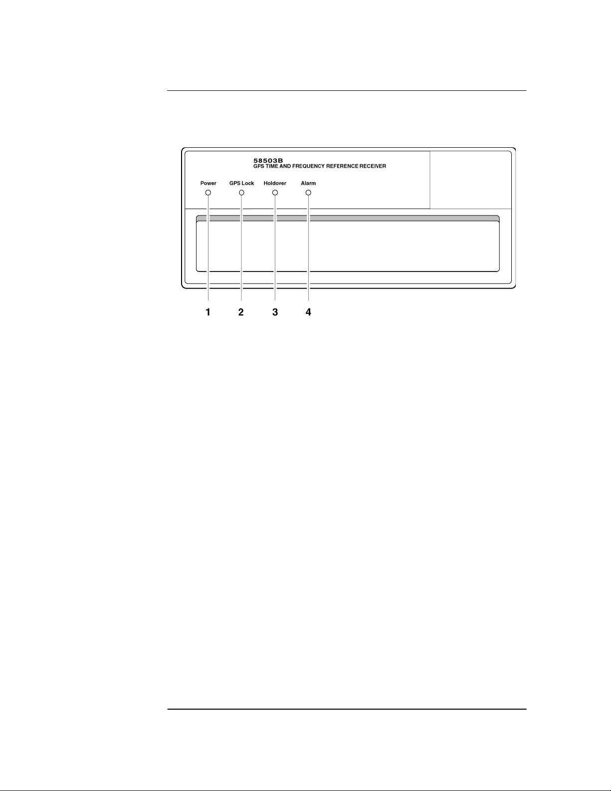
58503B Front Panel at a Glance
1 When the Power indicator
illuminates, it indicates that the
proper input power is supplied to the
Receiver.
2 When the GPS Lock indicator
illuminates, it indicates that the
Receiver is receiving the GPS signal
and is locked on one or more
satellite(s).
3 When the Holdover indicator
illuminates, it indicates that the
Receiver is NOT locked to the GPS
signal. The Receiver is keeping time
based on the internal reference
oscillator signal. The internal
reference oscillator will determine
the accuracy of the 1 PPS signal and
the 10 MHz reference output.
4 When the Alarm indicator
illuminates, it indicates that the
Receiver has detected an internal
condition that requires attention.
1-2 Operating and Programming Guide
Page 13
Chapter 1 Front and Rear Panels at a Glance
58503B/Option 001 Front-Panel Display/Keypad at a Glance
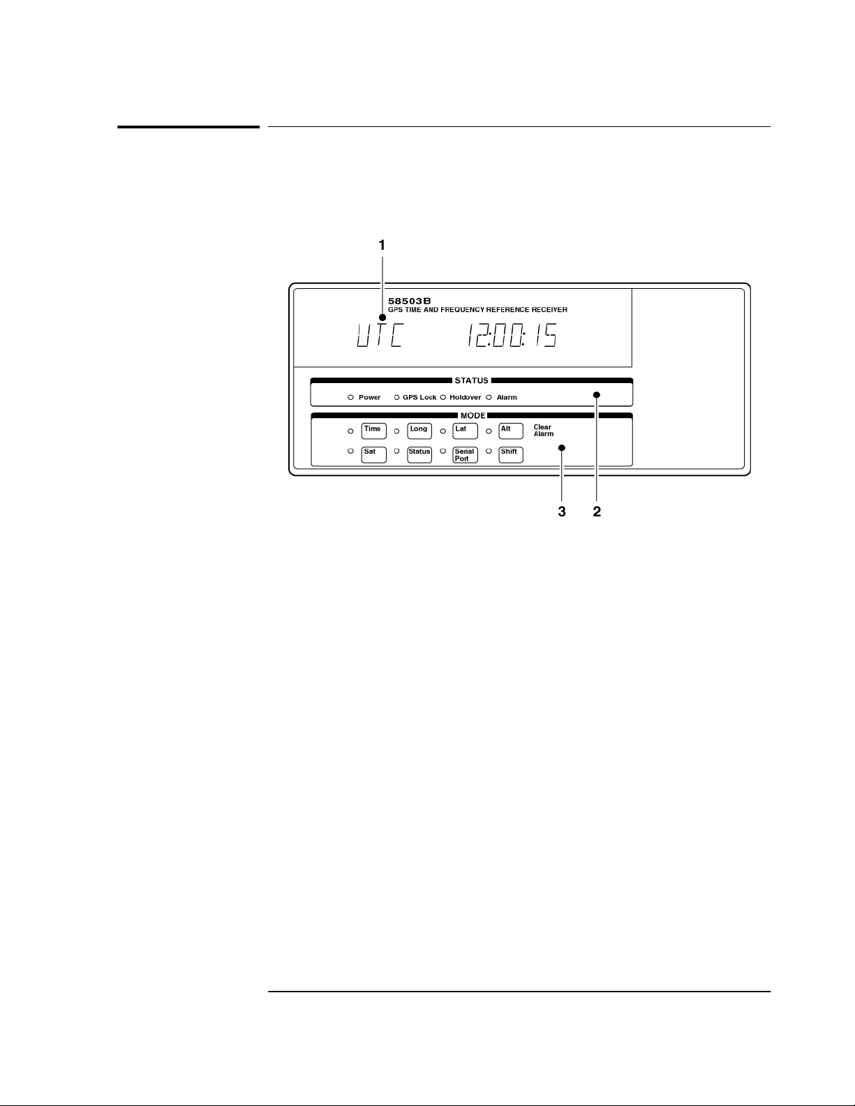
58503B/Option 001 Front-Panel
Display/Keypad at a Glance
1 An alphanumeric display for displaying time, position (i.e., longitude,
latitude, and altitude), and Receiver status. The display is a highly visible
twelve-character vacuum-fluorescent display.
2 Status LED indicators:
When the Power indicator is illuminated, it indicates that input power is
supplied to the Receiver.
When the GPS Lock indicator is illuminated, it indicates that the
Receiver is tracking satellites and has phase-locked its internal reference
to the reference provided by GPS.
When the Holdover indicator is illuminated, it indicates that the Receiver
is not phase-locking its internal reference to the reference provided by
GPS. Typically, this would happen due to loss of satellite tracking.
When the Alarm indicator is illuminated, it indicates that the Module has
detected a condition that requires attention.
3 Eight MODE keys with associated LEDs for front-panel access to time,
position, and status information: Time, Long (longitude), Lat (latitude)
Alt (altitude), Sat (number of satellites tracking), Status (Receiver or
system status), and Serial Port (serial port settings). Each key selects a
different display mode. Also, pressing Shift and Alt key in sequence clears
instrument alarm.
Operating and Programming Guide 1-3
Page 14
Chapter 1 Front and Rear Panels at a Glance
58503B Rear Panel at a Glance
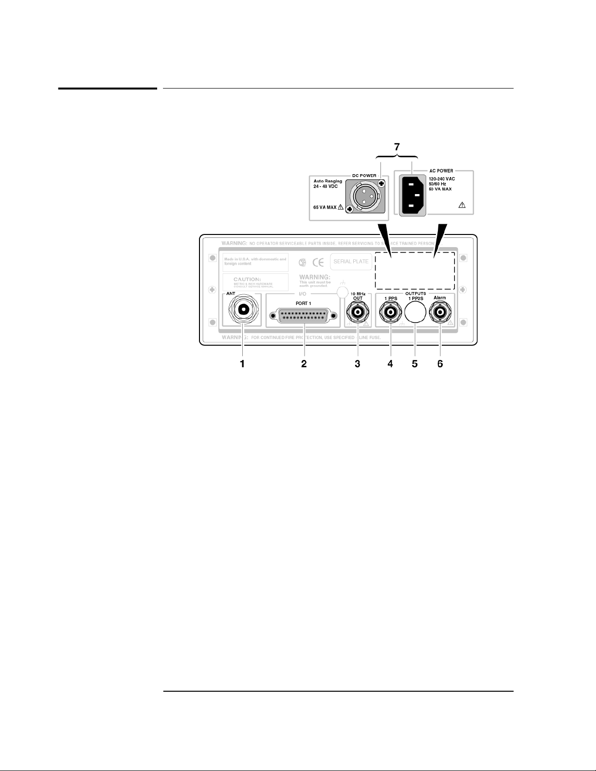
58503B Rear Panel at a Glance
1 ANT N-type (female) connector for
GPS Antenna connection.
2 PORT 1 RS-232C, DB-25 (female)
serial interface port for remote
control, monitoring, and
downloading of the Receiver’s
memory data and upgrading
Receiver software.
3 10 MHz OUT output for user-specific
applications.
4 1PPS connector for outputting a
continuous 1 Pulse Per Second
signal.
Option 002 1PP2S
(One-Pulse-Per-Two-Seconds)
connector for outputting a pulse
every other second, synchronized to
the even seconds in GPS time.
Pulses occur on even-numbered
seconds (i.e., 2 seconds, 4 seconds,
etc.).
6 Alarm output for external devices
(such as red light, bell, or horn) to
indicate that the Receiver has
detected an internal condition that
requires attention.
7 POWER input jack.
1-4 Operating and Programming Guide
Page 15

Chapter 1 Front and Rear Panels at a Glance
59551A Front Panel at a Glance
59551A Front Panel at a Glance
When the Power indicator
1
illuminates, it indicates that the
proper input power is supplied to
the Module.
2 When the GPS Lock indicator
illuminates, it indicates that the
Module is receiving the GPS signal
and is locked on one or more
satellite(s).
When the Holdover indicator
3
illuminates, it indicates that the
Module is NOT locked to the GPS
signal. The Module is keeping time
based on the internal reference
oscillator signal. The internal
reference oscillator will determine
the accuracy of the 1 PPS signal.
(See specification for Accuracy in
Holdover in Appendix F, “59551A
Specifications,” in this guide.)
4 When the Alarm indicator
illuminates, it indicates that the
Module has detected an internal
condition that requires attention.
5 PORT 2 RS-232C, DE-9S (female)
serial interface port for local
monitoring and retrieving data
stored in the Module’s memory
data.
Operating and Programming Guide 1-5
Page 16
Chapter 1 Front and Rear Panels at a Glance
59551A Rear Panel at a Glance
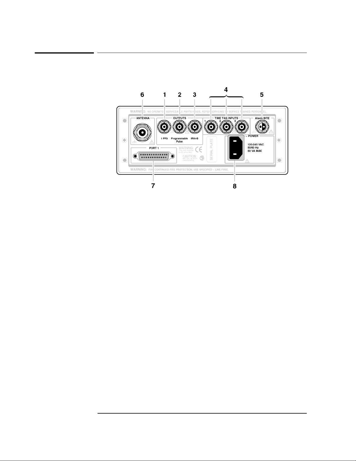
59551A Rear Panel at a Glance
1 1PPS (One-Pulse-Per-Second)
connector for outputting a
continuous one pulse per second
signal.
2 Programmable Pulse output connector
for outputting pulses at user-specified
time/period.
3 IRIG-B output for outputting
formatted time-code signals. (This
signal is used for general purpose
time distribution and magnetic
tape annotation applications
requiring the time of year.)
4 Time tag input connectors for
receiving TTL conditioned time
tagging signals.
5 Alarm BITE (Built-In Test
Equipment) output for external
devices (such as red light, bell, or
horn) to indicate that the Module
has detected an internal condition
that requires attention. The relay
opens and closes with the Alarm
indicator. (Mating connector is
Amphenol part number 31-224
[glass-filled Noryl] or #31-2226
[Telfon]).
6 ANTENNA N-type (female)
connector for GPS antenna
connection.
7 PORT 1 RS-232C, DB-25 (female)
serial interface port for remote
control, monitoring, and retrieving
of the Module’s memory data and
upgrading Module software.
8 AC POWER input jack. The AC
input jack is standard. The unit
operates from ac voltage. It can also
be operated from dc voltage via this
ac jack by using the supplied IEC
320 dc connector plug.
1-6 Operating and Programming Guide
Page 17

2
Serial Interface Capabilities
Page 18

Chapter 2 Serial Interface Capabilities
Chapter Contents
Chapter Contents
This chapter describes how to operate the 59551A GPS Measurements
Synchronization Module and the 58503B GPS Time and Frequency
Reference Receiver via the RS-232C serial interface port. Hardware
connections and configuration are discussed.
This chapter is organized as follows:
• About the RS-232C Serial Port(s) page 2-3
– PORT 1 Rear-Panel RS-232C Serial Port page 2-3
– PORT 2 Front-Panel RS-232C Serial Port
(59551A Only)
• Connecting a Computer or Modem page 2-5
– To Connect the GPS Receiver to a PC or Modem Via
the Rear-Panel PORT 1
– To Connect the GPS Receiver to a PC or Modem Via
the Rear-Panel PORT 1
• Configuring the RS-232C Port(s) page 2-9
– Making Changes to the Serial Port Settings
(If Needed)
– Determining the Serial Port Settings page 2-11
page 2-4
page 2-6
page 2-6
page 2-10
2-2 Operating and Programming Guide
Page 19

Chapter 2 Serial Interface Capabilities
About the RS-232C Serial Port(s)
About the RS-232C Serial Port(s)
The 58503B has only a rear-panel (PORT 1) RS-232C serial interface
port.
The 59551A has separate rear-panel (PORT 1) and front-panel
(PORT 2) RS-232C serial interface ports.
The rear-panel (PORT 1) RS-232C serial interface port is the only port
which can be used to upgrade the Receiver firmware; therefore, it is
referred to as the PRIMARY port. The 59551A’s front-panel (PORT 2)
RS-232C serial interface port is referred to as the SECONDARY port
because it cannot be used to upgrade the Receiver firmware. The
operation and configuration of these ports are described in the
following paragraphs. More information is provided in the sections
titled “Connecting a Computer or Modem” and “Configuring the
RS-232C Port(s)” in this chapter on page 2-5 and page 2-9,
respectively.
Either port allows you full communication with the Receiver. This can
be done by connecting any computer with an RS-232C serial interface
and suitable terminal emulation software, then sending the correct
commands for transmitting or retrieving data.
PORT 1 Rear-Panel RS-232C Serial Port
This 25-pin female subminiature D (DB-25) connector (PORT 1)
RS-232C Serial Interface Port is located on the rear panel.
The pins used for PORT 1 RS-232C communication are described in
Table 2-1.
NOTE We reserve the right to impose signals on other pins; therefore, your
connection should be restricted to the pins described in Table 2-1.
Table 2-1. PORT 1 Rear-Panel RS-232C Serial Port Connections
*Pin
Number
2 Output Transmit Data (TxD). GPS Receiver output.
3 Input Receive Data (RxD). GPS Receiver input.
7
Input/Output Description
_____
Signal Ground (SG)
Operating and Programming Guide 2-3
Page 20

Chapter 2 Serial Interface Capabilities
About the RS-232C Serial Port(s)
Refer to the sections titled “Connecting a Computer or Modem” in this
chapter, on page 2-5, for wiring diagrams and more information on the
RS-232C interface cables.
PORT 2 Front-Panel RS-232C Serial Port
(59551A Only)
This 9-pin female subminiature D (DB-9) connector (PORT 2) RS-232C
Serial Interface Port is located on the front panel.
The pins used for PORT 2 RS-232C communication are described in
Table 2-2.
NOTE We reserves the right to impose signals on other pins; therefore, your
connection should be restricted to the pins described in Table 2-2.
Table 2-2. PORT 2 Front-Panel RS-232C Serial Port Connections
(59551A Only)
*Pin
Number
2 Input Receive Data (RxD). GPS Receiver input.
3 Output Transmit Data (TxD). GPS Receiver output.
5
Input/Output Description
_____
Signal Ground (SG)
Refer to the sections titled “Connecting a Computer or Modem” in this
chapter, on page 2-5, for wiring diagrams and more information on the
RS-232C interface cables.
2-4 Operating and Programming Guide
Page 21

Chapter 2 Serial Interface Capabilities
Connecting a Computer or Modem
Connecting a Computer or Modem
To connect the GPS Receiver to a computer or modem, you must have
the proper interface cable. Most computers are DTE (Data Terminal
Equipment) devices. Since the Receiver is also a DTE device, you must
use a DTE-to-DTE interface cable when connecting to a computer.
These cables are also called “null-modem”, “modem-eliminator”, or
“crossover” cables.
Most modems are DCE (Digital Communication Equipment) devices;
thus, you must use a DTE-to-DCE interface cable.
The interface cable must also have the proper connector on each end
and the internal wiring must be correct. Connectors typically have
9 pins (DE-9 connector) or 25 pins (DB-25 connector) with a “male” or
“female” pin configuration. A male connector has pins inside the
connector shell and a female connector has holes inside the connector
shell.
To simplify interface cable selections, the following sections
tells you which cables to use.
Operating and Programming Guide 2-5
Page 22

Chapter 2 Serial Interface Capabilities
Connecting a Computer or Modem
To Connect the GPS Receiver to a PC or Modem Via
the Rear-Panel PORT 1
Connecting to the Personal Computer (PC)
Use an HP 24542G interface cable or equivalent to connect the
Receiver’s rear-panel PORT 1 DB-25 female connector to a PC as
shown in Figure 2-1. See “Making Your Own Cables” starting on
page 2-8.
GPS Receiver
(Rear view)
NO OPERATOR SERVICEABLE PARTS INSIDE, REFER SERVICING TO SERVICE TRAINED PERSONNEL.
WARNING:
1 pps Programmable
WARNING:
INPUTS
OUTPUTS
Time Tag1Time Tag2Time Tag
Irig-B
TOD
! !
Port 1
FOR CONTINUED FIRE PROTECTION, USE SPECIFIED ~ LINE FUSE.
SERIAL PLATE
FOR LABORATORY USE BY
QUALIFIED PERSONNEL
FOUR USAGE EN LABORATOIRE
PAR PERSONNEL QUALIFIE
ANTENNA
ALARM BITE
3
!
POWER
129 VDC
48 VDC
129 VDC
!
Computer
HP 24542G
or equivalent
Figure 2-1. Connecting the GPS Receiver to a PC or Laptop
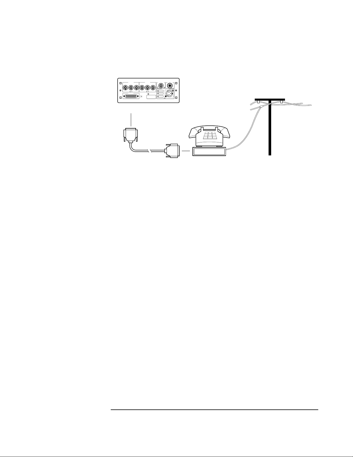
Connecting to a Modem
Use an HP 40242M interface cable or equivalent to connect the
Receiver’s rear-panel PORT 1 DB-25 female connector to a modem,
which is a DCE (Digital Communication Equipment) device, as shown
in Figure 2-2. See “Making Your Own Cables” starting on page 2-8.
2-6 Operating and Programming Guide
Page 23
Chapter 2 Serial Interface Capabilities
Connecting a Computer or Modem
GPS Receiver
(Rear view)
NO OPERATOR SERVICEABLE PARTS INSIDE, REFER SERVICING TO SERVICE TRAINED PERSONNEL.
WARNING:
OUTPUTS
1 pps Programmable
Irig-B
TOD
! !
Port 1
FOR CONTINUED FIRE PROTECTION, USE SPECIFIED ~ LINE FUSE.
WARNING:
INPUTS
Time Tag1Time Tag2Time Tag
FOR LABORATORY USE BY
QUALIFIED PERSONNEL
FOUR USAGE EN LABORATOIRE
PAR PERSONNEL QUALIFIE
SERIAL PLATE
ANTENNA
ALARM BITE
3
!
POWER
129 VDC
48 VDC
129 VDC
!
HP 40242M
or equivalent
Modem set to
Auto-Answer
Telephone
Line
Figure 2-2 Connecting the GPS Receiver to a Modem
Operating and Programming Guide 2-7
Page 24

Chapter 2 Serial Interface Capabilities
Connecting a Computer or Modem
Making Your Own Cables
If you choose to make your own cable, see Figure Figure 2-3 and
Figure Figure 2-4.
Figure Figure 2-3 illustrates how to make a DE-9S-to-DE-9P, DTEto-DCE interface cable that can replace the cable and adapter
combination of the HP 24542U cable and the HP 5181-6639 adapter for
use with PORT 2 of the 59551A.
RS-232C (9-pin)
PC input
PC output
Data
Terminal
Equipment
PC
RX
TX
GND
DE-9P
Male
DE-9S-to-DE-9P
(DTE-to-DCE) Interface Cable
11
22
33
44
55
66
77
88
99
DE-9S
Female
DE-9P
Male
Data
Communications
Equipment
59551A PORT 2
RS-232C (9-pin)
Instrument input
RX
Instrument output
TX
GND
DE-9S
Female
Figure 2-3 DE-9S-to-DE-9P (DTE-to-DCE) Serial Interface Connection
to PORT 2
Figure Figure 2-4 illustrates how to make a DE-9S-to-DB-25P,
DTE-to-DTE interface cable that can replace the HP 24542G cable
(25-pin male to 9-pin female connectors) for use with PORT 1.
RS-232C (9-pin)
PC input
PC output
Data
Terminal
Equipment
PC
RX
TX
GND
DE-9P
Male
1
2
3
4
5
6
7
8
9
DE-9S
Female
DE-9S-to-DB-25P
(DTE-to-DTE)
Interface cable
DB-25P
Male
Data
Terminal
Equipment
PORT 1
RS-232C (25-pin)
1
2
3
4
5
6
7
8
20
22
DB-25S
Female
TX
RX
GND
Instrument output
Instrument input
Figure 2-4 DE-9S-to-DB-25P (DTE-to-DTE) Serial Interface
Connection to PORT 1
2-8 Operating and Programming Guide
Page 25

Chapter 2 Serial Interface Capabilities
Configuring the RS-232C Port(s)
Configuring the RS-232C Port(s)
The 59551A has separate rear-panel (PORT 1) and front-panel
(PORT 2) RS-232C serial interface ports.
The 58503B has one RS-232C serial interface port (PORT 1) on the
rear panel. Note: PORT 1 of the 58503B and PORT 2 of the 59551A
have the same configuration capabilities as indicated in Table 2-4.
Software pacing, baud rate, parity, data bits, and stop bits parameters
for each port are user-selectable and independent of the configuration
of the other.
Table 2-3 and Table 2-4 list the configuration factory-default values for
PORT 1 and PORT 2.
Table 2-3. Factory-Default Values for PORT 1 of the 59551A
Parameter Default Possible Choices
Software Pacing NONE XON or NONE
Baud Rate 9600 1200, 2400, 9600, or 19200
Parity NONE EVEN, ODD, or NONE
Data Bits 8 7 or 8
Stop Bits 1 1 or 2
Full Duplex ON ON or OFF
Table 2-4. Factory-Default Values for PORT 1 or the 58503B and
PORT 2 of the 59551A
Parameter Default Possible Choices
Software Pacing NONE XON or NONE
Baud Rate 9600 1200, 2400, 9600, or 19200
Parity NONE EVEN, ODD, or NONE
Data Bits 8 Fixed at 7 when parity is even or odd.
Fixed at 8 when parity is none.
Stop Bits 1 Fixed (no choices available)
Full Duplex ON ON or OFF
Procedures for configuring the RS-232C ports are provided in the
following paragraphs.
Operating and Programming Guide 2-9
Page 26

Chapter 2 Serial Interface Capabilities
Configuring the RS-232C Port(s)
Making Changes to the Serial Port Settings
(If Needed)
CAUTION If you change the serial port settings, your changes will be
stored in the Receiver. Cycling power will not reset to factory
defaults. Therefore, if you make a change, it is recommended
that you record the settings and keep the record with the
Receiver.
If you need to change the serial port settings, for example, to set
up for a different computer, use the guidelines given in this
section.
Serial port settings are changed by issuing commands.
It is recommended that you issue a single compound command which
simultaneously sets all the serial port parameters. Then connect the
other computer and begin using the instrument with the new settings.
NOTE If you choose to set parameters one at a time, you will make the
procedure more difficult. That is, with each change, the instrument
will be updated, but your computer will retain its original settings.
At each step, you will have stopped serial communications and be
forced to modify your PC settings to match the Receiver in order to
continue. It is recommended that you make all changes in a single
compound command, verify the changes, and record all parameters.
Configuring PORT 1 of the 59551A
Complete configuration of PORT 1 of the 59551A requires that you set
five parameters. The command line sent in the following example
would set the RS-232C port pacing to XON, baud rate to 2400, parity to
EVEN, data bits to 7, and stop bits to 2. This command line must be
transmitted on PORT 1.
SYST:COMM:SER:PACE XON; BAUD 2400; PARITY EVEN; BITS 7; SBITS 2
Configuring PORT 1 of the 58503B and PORT 2 of the
59551A
Complete configuration of PORT 1 (58503B) and PORT 2 (59551A)
require that you set three parameters. The command line sent in the
following example would set the RS-232C port pacing to XON, baud
rate to 2400, and parity to EVEN. This command line must be
transmitted on PORT 1 or PORT 2.
SYST:COMM:SER2:PACE XON; BAUD 2400; PARITY EVEN
2-10 Operating and Programming Guide
Page 27

Chapter 2 Serial Interface Capabilities
Configuring the RS-232C Port(s)
Determining the Serial Port Settings
Standard 58503B and 59551A
If you connect your PC, press Return, and do not get a scpi> prompt
back from the Receiver, your Receiver’s serial communication settings
may have been modified. You need to systematically step through the
data communication settings on your PC until your PC matches the
Receiver. The Receiver cannot communicate its settings until this
process is complete.
Iterate until you are able to verify that settings on your PC match the
Receiver.
When you are successful, you will have restored full RS-232C
communications, enabling you to query the Receiver’s communication
settings. Once you establish communications with one serial port, you
can query the Receiver for settings of either port.
Issue the following queries to either serial port to verify PORT 1’s
configuration.
SYST:COMM:SER:PACE?
SYST:COMM:SER:BAUD?
SYST:COMM:SER:PARITY?
SYST:COMM:SER:BITS?
SYST:COMM:SER:SBITS?
Issue the following queries to either serial port to verify PORT 2’s
configuration.
SYST:COMM:SER2:PACE?
SYST:COMM:SER2:BAUD?
SYST:COMM:SER2:PARITY?
SYST:COMM:SER2:BITS?
SYST:COMM:SER2:SBITS?
Operating and Programming Guide 2-11
Page 28

Chapter 2 Serial Interface Capabilities
Configuring the RS-232C Port(s)
This page intentionally left blank.
2-12 Operating and Programming Guide
Page 29

3
Visual User Interface
Using the Receiver Status Screen
Page 30

Chapter 3 Visual User Interface
Chapter Contents
Chapter Contents
This chapter provides a tutorial section on how to use the Receiver
Status Screen, a comprehensive reference information section, and an
illustrated foldout of the Receiver Status Screen, which is a
comprehensive summary of key operation conditions and settings.
This chapter is organized as follows:
• Using and Reading the Visual User Interface (the
Receiver Status Screen)
– Tutorial on Using the Status Screen to Interface With
the Receiver page 3-3
– Demonstration of Holdover Operation page 3-8
• Receiver Status Screen Data page 3-11
– SYNCHRONIZATION Section of the Status Screen page 3-12
– ACQUISITION Section of the Status Screen page 3-14
– HEALTH MONITOR Section of the Screen page 3-18
• The Receiver Status Screen at a Glance (foldout) page 3-20
page 3-3
3-2 Operating and Programming Guide
Page 31

Chapter 3 Visual User Interface
Using and Reading the Visual User Interface (the Receiver Status
Screen)
Using and Reading the Visual User
Interface (the Receiver Status Screen)
The combination of the PC and the GPS Receiver yields a visual user
interface called the Receiver Status Screen that lets you see what the
Receiver is doing and how it is progressing towards tracking satellites
to eventually lock to the GPS signal.
When connected to a properly configured PC, the Receiver Status
Screen can be accessed. There are two ways to access and use the
Receiver Status Screen:
• By installing a commercially available terminal emulation
program, connecting the Receiver to a PC via the PORT 1 port, and
manually sending the
“Getting Started,” in 58503B/59551A Getting Started Guide.)
:SYSTEM:STATUS?
query. (Refer to Chapter 1,
• By installing and operating the SatStat program, which
automatically generates continual status screen updates, and
connecting the Receiver to a PC via PORT 1. (Refer to the sections
titled “Installing the Automated SatStat Program for Continual
Status Updates” and “Operating the Automated SatStat Program”
in Chapter 1, “Getting Started,” of the 58503B/59551A Getting
Started Guide for details on installation and operation.)
The following tutorial demonstrates how you can use the Receiver
Status Screen to observe Receiver operation. The tutorial uses the
manual (
:SYSTEM:STATUS?
) method.
Tutorial on Using the Status Screen to Interface With
the Receiver
:SYSTEM:STATUS?
Type
An initial power-up screen is displayed, which is similar to the
demonstration screen shown in Figure 3-1. The first data that you
should look at is in the SYNCHRONIZATION area of the screen. It is
telling you that it is in the Power-up state as indicated by the >>
marker. That is, the Receiver has just been put on line.
at the scpi> prompt.
Operating and Programming Guide 3-3
Page 32

Chapter 3 Visual User Interface
Using and Reading the Visual User Interface (the Receiver Status
Screen)
---------------------------- ---------------------------SYNCHRONIZATION
SmartClock Mode
Locked
Recovery
Holdover
>>
Power-up:GPS acquisition
ACQUISITION
Tracking: 0
ELEV MASK
HEALTH MONITOR
Self Test: OK Int Pwr: OK Oven Pwr: OK OCXO: OK EFC: OK GPS Rcv: OK
10 deg
.........................................
.............................................
Not Tracking: 6
PRN
El Az
*1 -- --*6 -- --*9 -- ---
*14 -- --*22 -- --*24 -- ---
*attempting to track
......................................................
Receiver Status
Outputs Invalid
Reference Outputs
TFOM
1PPS TI
HOLD THR
Holdover Uncertainty
Predict --
Time
UTC
GPS 1PPS Invalid: not tracking
ANT DLY
Position
MODE
INIT LAT
INIT LON
INIT HGT
[
9
--
1.000 us
[GPS 1PPS Invalid]
12:00:00[?] 01 Jan 1996
0 ns
Survey: 0% complete
Suspended:track <4 sats
NW0:00:00.000
0:00:00.000
FFOM
0 m (GPS)
[ OK ]
Figure 3-1. Receiver Status Screen at Powerup
The ACQUISITION area of the screen is telling you that no satellites
have been tracked. The identification numbers of several satellites
appear in the Not Tracking column. The asterisk next to the satellite
identification number, or pseudorandom noise code (PRN), indicates
the Receiver is attempting to track it.
]
3
The current time and date are shown in the Time quadrant of the
ACQUISITION area. The default power-up setting, indicated by [?], is
corrected when the first satellite is tracked. Since the Receiver is not
tracking any satellites, the GPS 1 PPS reference signal is invalid.
An accurate position is necessary to derive precise time from GPS. The
Position quadrant indicates that the Receiver is in survey mode, which
uses GPS to determine the position of the GPS antenna. This process
has not yet started, since position calculations can be performed only
while tracking four or more satellites. INIT LAT, INIT LON, and INIT
HGT are the initial estimate of the true position. These coordinates are
refined by the survey process. The Receiver uses this position and the
time-of-day to select satellites to track. Therefore, you can reduce
satellite acquisition time by specifying a close approximation of
position and time.
Now, let’s send the
:SYSTEM:STATUS?
query again to see what kind of
progress the Receiver has made.
3-4 Operating and Programming Guide
Page 33

Chapter 3 Visual User Interface
Using and Reading the Visual User Interface (the Receiver Status
Screen)
You can now see that the Receiver is tracking several satellites as
shown in Figure 3-2. The process of acquiring and tracking satellites is
described in the following paragraphs.
---------------------------- ---------------------------SYNCHRONIZATION
SmartClock Mode
Locked to GPS: stabilizing frequency
>>
Recovery
Holdover
Power-up
ACQUISITION
Tracking: 5
PRN El Az
El
70
46
33
28
65
Az
337
188
82
113
91
2
7
15
19
22
ELEV MASK
HEALTH MONITOR
Self Test: OK Int Pwr: OK Oven Pwr: OK OCXO: OK EFC: OK GPS Rcv: OK
...........................
...............................................
10 deg
Not Tracking: 4
PRN
C/N
49
48
38
36
49
9 11 292
16 24 243
*26 Acq..
31 -- ---
*attempting to track
......................................................
Receiver Status
[
Outputs Valid/Reduced Accuracy
Reference Outputs
TFOM FFOM
1PPS TI
HOLD THR
Holdover Uncertainty
Predict --
Time
UTC
GPS 1PPS Synchronized to UTC
ANT DLY
Position
MODE
AVG LAT
AVG LON
AVG HGT
61
+71 ns relative to GPS
1.000 us
[GPS 1PPS Valid]
17:56:44 31 Jan 1996
0 ns
Survey: 1.2% complete
NW37:19:34.746
121:59:50.502
+34.14 m (GPS)
[ OK ]
Figure 3-2. Receiver Status Screen Displaying Initial Satellite
Acquisition
An asterisk (*) next to the PRN of a satellite in the Not Tracking
column indicates the Receiver is attempting to track it. The elevation
(El) and azimuth (Az) angles of the satellite are indicated. Acq . or
Acq .. tell you that the Receiver is attempting to track that satellite.
One dot after the Acq indicator shows that the Receiver is attempting
to acquire its signal, and two dots indicate impending lock. Eventually,
you will see the satellite move to the Tracking column, which shows
the satellite PRN, the elevation angle of the satellite in the sky (90
being zenith), the azimuth angle (number of degrees bearing from true
north), and the carrier-to-noise ratio (C/N). A good carrier-to-noise
ratio is a number above 35, which would be efficient for the Receiver to
operate. Numbers below 35, suggest intermittent tracking of the
satellite or no tracking; check your antenna system should this be the
case.
]
°
As indicated by the demonstration screen in Figure 3-2, the Receiver is
now surveying for position. It is tracking four satellites which is the
minimum number that must be tracked to determine postion. As you
can see, the Position MODE line indicates survey is 1.2% complete. A
complete survey would take two hours during which four satellites or
more are continuously tracked.
Operating and Programming Guide 3-5
Page 34

Chapter 3 Visual User Interface
Using and Reading the Visual User Interface (the Receiver Status
Screen)
Also, you can see the initial (estimated) position has been replaced
with a computed position, which the Receiver continuous to refine until
it gets a very accurate position. The status screen indicates that a
computed position is being used by displaying the averaged latitude,
and longitude height (AVG LAT, AVG LON, and AVG HGT).
If the position were not precise, GPS timing information would be
inaccurate by an amount corresponding to the error in the computed
position. An error in the computed position of the antenna translates
into an error in the derived time and will compromise the Receiver’s
ability to be a timing source.
Let’s consider a case where four satellites are not visible at powerup
because of a poor antenna location, such as an “urban canyon” (located
between tall city buildings). If accurate position is known from a
Geodetic survey of that site, it can be programmed with the position
command, thereby bypassing the survey operation. This is useful when
four satellites cannot be tracked for an extended period of time.
Let’s send the
:SYSTEM:STATUS?
query again to observe the current
status of the Receiver.
The updated demonstration status screen in Figure 3-3 indicates that
the position survey is now 5.4% complete. Thus, the survey task is
beginning to iterate toward an accurate position. In the Time
quadrant, the UTC time is now correct. The date is correct, and the
GPS reference signal is synchronized to UTC.
3-6 Operating and Programming Guide
Page 35

Chapter 3 Visual User Interface
Using and Reading the Visual User Interface (the Receiver Status
Screen)
---------------------------- ---------------------------SYNCHRONIZATION
SmartClock Mode
Locked to GPS: stabilizing frequency
>>
Recovery
Holdover
Power-up
ACQUISITION
Tracking: 6
PRN El Az
El
70
35
40
71
19
Az
301
186
102
60
317
2
7
19
22
26
31 3516 41
ELEV MASK
HEALTH MONITOR
Self Test: OK Int Pwr: OK Oven Pwr: OK OCXO: OK EFC: OK GPS Rcv: OK
............................
...............................................
Not Tracking: 1
C/N
PRN
40
16 13 258
38
38
39
36
10 deg
......................................................
Receiver Status
Outputs Valid/Reduced Accuracy
[
Reference Outputs
TFOM FFOM
1PPS TI
HOLD THR
Holdrover Uncertainty
Predict 432.0 us/initial 24 hrs
Time
UTC
GPS 1PPS Synchronized to UTC
ANT DLY
Position
MODE
AVG LAT
AVG LON
AVG HGT
41
+20 ns relative to GPS
1.000 us
[GPS 1PPS Valid]
18:47:07 31 Jan 1996
0 ns
Survey: 5.4% complete
NW37:19:34.937
121:59:50.457
+67.94 m (GPS)
[ OK ]
Figure 3-3. Receiver Status Screen Displaying Progress Towards
Steady-State Operation
In the SYNCHRONIZATION area, the >> marker is pointed at the
Locked to GPS line, indicating that the Receiver is locked to GPS and
stabilizing the frequency of its oscillator. This means that the Receiver
has phase-locked its oscillator to the 1 PPS reference signal provided
by GPS, but it is not at its final, or most stable, state. The Receiver is
locked and the front-panel GPS Lock LED is illuminated.
]
For users without the command interface (PC/Terminal emulator
connected to the Receiver), the illuminated GPS Lock LED is probably
the first indication that after powerup that the Receiver is moving
towards a stable state.
With the command interface and status screen, you can get more
detailed information. For example, you can read the reference outputs
quality indicators in the Reference Outputs area of the status screen.
These are the Time Figure of Merit (TFOM) and Frequency Figure of
Merit (FFOM) indicators. As shown in Figure 3-3, the TFOM is 4 and
the FFOM is 1. These values will eventually decrease towards the
ultimate values that represent steady-state performance. Refer to the
subsection titled ““Reference Outputs” on page 3-13 in this chapter for
more information about TFOM and FFOM.
Operating and Programming Guide 3-7
Page 36

Chapter 3 Visual User Interface
Using and Reading the Visual User Interface (the Receiver Status
Screen)
Also indicated is a prediction of the accuracy of the Receiver should it
go into holdover operation.
Demonstration of Holdover Operation
CAUTION The Receiver typically reaches stable state 24 to 72 hours after
powerup, and it will learn best if its experiences no holdover in the first
24 hours. Therefore, the holdover demonstration in the following
paragraphs will compromise the Receiver’s ability to learn the
characteristics of its internal reference oscillator. For the purpose of
education only, you will be shown how to initiate a holdover.
A user should never initiate holdover during the first 24 hours while
the Receiver is learning its internal oscillator characteristics. The
Receiver should maintain GPS lock during this time because it is using
the GPS signal to discipline the oscillator. It will learn what the
oscillator drift characteristics are relative to the GPS signal. It will
learn how the oscillator ages, and the software will learn how to
compensate for that aging.
Thus, it is recommended that the Receiver is always kept locked to
GPS during the first 24 hours.
For demonstration purposes, and since the Receiver has been powered
up for a while, let’s put the Receiver into holdover by simply removing
the antenna connection. (Note that holdover also can be manually
initiated by sending the
SYNCHRONIZATION:HOLDOVER:INITIATE
command; however, for this demonstration, disconnect the antenna
cable.) The following will occur after a verification delay:
• The front-panel Holdover LED will illuminate, and
• after sending the
:SYSTEM:STATUS?
query again, a screen similar to
Figure 3-4 should appear.
Let’s send the
:SYSTEM:STATUS?
query. Figure 3-4 should appear.
3-8 Operating and Programming Guide
Page 37

Chapter 3 Visual User Interface
Using and Reading the Visual User Interface (the Receiver Status
Screen)
---------------------------- ---------------------------SYNCHRONIZATION
SmartClock Mode
Locked to GPS
Recovery
Holdover: GPS 1PPS invalid
>>
Power-up
ACQUISITION
Tracking: 0
ELEV MASK
HEALTH MONITOR
Self Test: OK Int Pwr: OK Oven Pwr: OK OCXO: OK EFC: OK GPS Rcv: OK
...........................
Holdover Duration: 0m 14s Present 1.0 us
.............................................
Not Tracking: 7
PRN
El Az
*2 71 316
*7 41 186
15 11 86
*19 35 107
*22 68 78
*26 23 314
10 deg
*attempting to track
......................................................
Receiver Status
PRN El Az
*31 12 29
[
Outputs Valid/Reduced Accuracy
Reference Outputs
TFOM FFOM
1PPS TI -HOLD THR
Holdover Uncertainty
Predict 432.0 us/initial 24 hrs
Time
UTC
GPS 1PPS Inaccurate: not tracking
ANT DLY
Position
MODE
LAT
LON
HGT
32
1.000 us
[GPS 1PPS Invalid]
20:56:14 31 Jan 1996
0 ns
Survey: 71.1% complete
NW37:19:32.472
121:59:51.784
+42.19 m (GPS)
[ OK ]
Figure 3-4. Receiver Status Screen Displaying Holdover Operation
In the SYNCHRONIZATION area, you can see that the Receiver has
gone into holdover as indicated by >> marker that is pointing at the
Holdover line. The status screen indicates that the reason the Receiver
is in holdover is because the GPS 1 PPS reference signal is invalid.
]
You would expect this since the antenna has been disconnected.
The status screen shows loss of the GPS signal. As you can see on the
screen, all of the satellites in the Tracking column moved into the Not
Tracking column.
The status screen in Figure 3-4 shows that the Receiver has been in
holdover operation for 14 seconds.
If the Receiver SmartClock had had enough time to learn the internal
oscillator characteristics, the Receiver Status Screen would show that
the Receiver went into holdover, and the Receiver’s outputs were
maintained during holdover by the SmartClock.
Operating and Programming Guide 3-9
Page 38

Chapter 3 Visual User Interface
Using and Reading the Visual User Interface (the Receiver Status
Screen)
When the GPS antenna is re-connected and the GPS signal has been
re-acquired, the Receiver has the ability to recover from holdover by
itself. The SYNCHRONIZATION area of the screen will show the
>>
marker pointing at the Recovery line (and then eventually at the
Locked to GPS line), the GPS Lock LED will illuminate, and the screen
will look similar toFigure 3-5.
---------------------------- ---------------------------SYNCHRONIZATION
SmartClock Mode
Locked to GPS: Stabilizing frequency
>>
Recovery
Holdover
Power-up
ACQUISITION
Tracking: 6
PRN
2
7
19
22
26
31 12 27
ELEV MASK
HEALTH MONITOR
Self Test: OK Int Pwr: OK Oven Pwr: OK OCXO: OK EFC: OK GPS Rcv: OK
71
34
41
67
24
Az
317
185
101
80
312
............................
...............................................
Not Tracking: 0
C/NEl
40
38
37
40
37
36
10 deg
......................................................
Receiver Status
[
Outputs Valid/Reduced Accuracy
Reference Outputs
TFOM FFOM
1PPS TI +10.6 ns relative to GPS
HOLD THR
Holdover Uncertainty
Predict 432.0 us/initial 24 hrs
Time
UTC
GPS 1PPS Synchronized to UTC
ANT DLY
Position
MODE
LAT
LON
HGT
31
1.000 us
[GPS 1PPS Valid]
20:59:28 31 Jan 1996
0 ns
Survey: 71.4% complete
NW37:19:32.486
121:59:52.082
+40.06 m (GPS)
[ OK ]
Figure 3-5. Receiver Status Screen Following Recovery from
Holdover Operation
You can see the Receiver has recovered from holdover almost
immediately and it has returned to locked operation.
]
3-10 Operating and Programming Guide
Page 39

Chapter 3 Visual User Interface
Receiver Status Screen Data
Receiver Status Screen Data
This section defines the data displayed in the Receiver Status Screen,
shown in Figure 3-6.
---------------------------- ---------------------------SYNCHRONIZATION
SmartClock Mode
>>
Locked to GPS
Recovery
Holdover
Power-up
ACQUISITION
Tracking: 6
El Az
PRN
2 49 243
16 24 282
18 38 154
19 65 52
27 62 327
31 34 61
ELEV MASK
HEALTH MONITOR
Self Test: OK Int Pwr: OK Oven Pwr: OK OCXO: OK EFC: OK GPS Rcv: OK
..........................................
................................................
Not Tracking: 1
C/N
PRN El Az
49
14 11 82
46
47
49
49
47
10 deg
......................................................
Receiver Status
[
Reference Outputs
TFOM FFOM
1PPS TI +7.2 ns relative to GPS
HOLD THR
Holdover Uncertainty
Predict 49.0 us/initial 24 hrs
Time
UTC
GPS 1PPS Synchronized to UTC
ANT DLY
Position
MODE
AVG LAT
AVG LON
AVG HGT
30
1.000 us
+1 leap second pending
23:59:59 31 Dec 1995
120 ns
Survey: 17.5% complete
NW37:19:32.264
121:59:52.112
Outputs Valid
[GPS 1PPS Valid]
+41.86 m (GPS)
[ OK ]
Figure 3-6. Sample Status Screen
The status screen has three major sections:
]
• SYNCHRONIZATION
• ACQUISITION
• HEALTH MONITOR
The SYNCHRONIZATION section of the status screen shows how the
GPS Receiver’s SmartClock
technology is progressing towards its
objective, which is to synchronize the Receiver’s oscillator to the 1 PPS
reference signal produced by the Receiver’s internal GPS Engine.
The ACQUISITION section of the status screen shows how the
Receiver’s internal GPS Engine is progressing towards its objective,
which is to produce an accurate internal 1 PPS reference signal. It does
so through tracking GPS satellites.
The HEALTH MONITOR section of the status screen summarizes the
overall health of the product.
Operating and Programming Guide 3-11
Page 40

Chapter 3 Visual User Interface
Receiver Status Screen Data
SYNCHRONIZATION Section of the Status Screen
SYNCHRONIZATION Summary Line
The SYNCHRONIZATION line in the screen summarizes the
SmartClock Status and Reference Outputs. One of three
SYNCHRONIZATION messages is shown:
Outputs Invalid while the Receiver (unit) is warming up,
Outputs Valid/
Reduced Accuracy while the unit is in holdover or is locked but has
not achieved steady-state operation, or
Outputs Valid while the unit is in steady-state operation.
SmartClock Mode
The SmartClock Mode area of the screen shows the four operating
modes:
•Locked to GPS
• Recovery
•Holdover
• Power-up
As shown in the sample status screen in Figure 3-6, a >> symbol
indicates the current operating mode.
Locked to GPS indicates that the Receiver is locked to GPS. The
front-panel GPS Lock LED will be illuminated.
When stabilizing frequency ... is shown, the time output (1 PPS) signal is
locked and can be used, but the frequency outputs (10 MHz) are not at
their final or most stable state.
Recovery indicates that the Receiver is actively working to become
locked to GPS. All conditions needed to proceed towards a lock have
been met. Expect an eventual spontaneous transition to a lock (unless
changing external conditions prevent this, such as loss of tracked
satellites.)
Holdover indicates that the Receiver is waiting for conditions that are
needed to allow the process of recovery from holdover to begin. Once
these conditions are met, the Receiver will transition on its own to the
recovery mode.
When the GPS 1PPS CLK invalid message follows the Holdover label,
the internal GPS 1 PPS reference signal is inaccurate.
3-12 Operating and Programming Guide
Page 41

Chapter 3 Visual User Interface
Receiver Status Screen Data
When the manually initiated message follows the Holdover label, the
Receiver has been placed in holdover by the user. An explicit command
is required to initiate an exit from manual holdover.
When the 1 PPS TI exceeds hold threshold message follows the
Holdover label, the phase difference between the 1 PPS time output
signal and the internal GPS 1 PPS reference signal has exceeded the
user-entered holdover threshold value.
When the internal hardware problem message follows the Holdover
label, a measurement hardware error exists.
The Holdover Duration message indicates the duration that the Receiver
has been operating in holdover (and recovery). Thus, this message
gives you an assessment of the quality of the outputs. The longer the
Receiver is in holdover the more degraded the outputs become.
Power-up indicates that the Receiver hasn’t yet achieved GPS lock or
acquired satellites since it has been powered up. The Receiver is
measuring the internal reference oscillator’s frequency and adjusting it
to 10 MHz during this power-up period. Other queries can provide
insight as to the cause if the Receiver is remaining in powerup longer
than expected.
Reference Outputs
TFOM (Time Figure of Merit) indicates the accuracy of the Receiver’s
internal 1 PPS signal. A low TFOM value indicates a more accurate
signal. In the sample screen of Figure 3-6, a value of 3 is displayed,
meaning that the Time Error ranges from 100 to 1000 nanoseconds.
The following table lists the TFOM values that could be displayed and
the corresponding Time Error.
Time Error
TFOM Value
*0 less than 1 5 104 – 10
*1 1 – 10 6 105 – 10
*2 10 – 100 7 106 – 10
3 100 – 1000 8 107 – 10
4 103 – 10
The TFOM values 0, 1, and 2 are not presently used in the Receiver. The Receiver will display
*
TFOM values ranging from 9 to 3, which is consistent with the specified accuracies of each product.
(in nanoseconds)
4
TFOM Value
9 greater than 10
Time Error
(in nanoseconds)
5
6
7
8
8
Operating and Programming Guide 3-13
Page 42

Chapter 3 Visual User Interface
Receiver Status Screen Data
FFOM (Frequency Figure of Merit) indicates the stability of the
Receiver’s internal 10 MHz signal. The 10 MHz signal is controlled by
the SmartClock’s Phase-Locked Loop (PLL). Thus, the FFOM value is
determined by monitoring the status of the PLL.
In the sample screen of Figure 3-6, the 0 indicates that the
SmartClock’s PLL is stabilized. The following table lists and defines
the FFOM values that could be displayed.
FFOM Value Definition
0 PLL stabilized — internal 10 MHz signal within
specification.
1 PLL stabilizing
2 PLL unlocked (holdover) — Initially the 10 MHz signal
will be within specifications. However, when in holdover,
the 10 MHz signal will eventually drift out of
specification.
3 PLL unlocked (not in holdover) — Do not use the output.
1PPS TI indicates the difference (timing shift) between the SmartClock
1 PPS and the internal GPS 1 PPS signals.
HOLD THR (holdover threshold) displays the user-entered time error
value.
ACQUISITION Section of the Status Screen
ACQUISITION Line
The ACQUISITION line in the screen summarizes the state of the
internal GPS Engine as indicated by the Tracking, Not Tracking, and
Position areas of the screen.
If the Receiver Engine was considered to be synchronized to the GPS
signal, the [GPS 1 PPS Valid] message will appear at the end of the
ACQUISITION line. If the Receiver has not yet synchronized to GPS,
the [GPS 1 PPS CLK Invalid] message will be displayed.
Tracking, Not Tracking
The Tracking table indicates the number of satellites the Receiver is
tracking.
The Not Tracking table indicates satellites predicted to be visible that
are not tracked, and all of the satellites that are assigned to a GPS
Engine channel but are not currently tracked.
3-14 Operating and Programming Guide
Page 43

Chapter 3 Visual User Interface
Receiver Status Screen Data
Health and status indicators in the tables are defined as follows:
PRN indicates the pseudorandom noise code assigned to the
satellite.
El indicates the predicted elevation angle, from a range of 0
°
. The predicted elevation is derived from the
to 90
almanac.
- - indicates that the elevation angle is unknown (the
almanac did not provide this data).
Az indicates the predicted azimuth angle, from a range of 0
°
to 359
. The predicted azimuth angle is referenced to true
north, and is derived from the almanac.
- - - indicates that the azimuth angle is unknown (the
almanac did not provide this data).
C/N
(58503B)
indicates the carrier-to-noise ratio of the received the
signal, from a range of 26 to 55. A ratio below 35 is a
weak signal that may not be acquired by the Receiver.
or
SS
(59551A)
indicates the strength of the signal, from a range of 0 to
255. A signal strength of 20 to 30 is a weak signal that
may not be acquired by the Receiver.
The health and status indicators in the Not Tracking table are
described as follows:
Ignore indicates that the user has chosen to exclude this
satellite from a list of satellites available for tracking.
Not OK indicates GPS has reported that this satellite is
unhealthy.
Acq indicates the unit is attempting to acquire the satellite
signal.
Acq . indicates the unit is reading timing information from
the satellite.
Acq . . indicates the unit is reading satellite orbital
information.
ELEV MASK indicates the elevation mask angle in degrees. Satellites
at or above this elevation angle are considered for
tracking.
*attempting
to track
indicates that the Receiver is attempting to track a
satellite.
Operating and Programming Guide 3-15
Page 44

Chapter 3 Visual User Interface
Receiver Status Screen Data
Time
When you first power up the unit the time and date that is stored in
the internal GPS Engine may not be the actual date. The actual time
and date will be valid after one satellite has been tracked by the
Receiver.
NOTE There are two accurate ways to express time (GPS or UTC). GPS time
is offset from UTC time by the number of accumulated leap seconds
since midnight of January 6, 1980 UTC.
The Time area of the status screen provides three types of information:
Time, 1PPS CLK, and ANT DLY.
Time has four possible modes: GPS, UTC, LOCL GPS, and LOCAL.
GPS indicates current time and date collected from a satellite in GPS
Time.
LOCL GPS indicates GPS Time, offset for the local time zone.
UTC indicates current time and date collected from a satellite in UTC
time.
LOCAL indicates current time and date collected from a satellite offset
from UTC for the local time zone.
1PPS CLK can indicate several possible advisory messages. These
messages are:
Synchronized
to GPS Time
Synchronized
To U T C
Assessing
stability ...
Inaccurate,
not tracking
Inaccurate,
inacc position
Absent or freq
incorrect
1 PPS locked to GPS, referenced to GPS Time.
1 PPS locked to GPS, referenced to UTC.
applying hysteresis to locked 1 PPS signal.
not tracking satellites.
in survey mode, but has not yet calculated a position.
no 1PPS signal; or the internal GPS Engine is idle.
3-16 Operating and Programming Guide
Page 45

Chapter 3 Visual User Interface
Receiver Status Screen Data
ANT DLY (antenna delay) displays the user-entered value that is used
to compensate for the propagation delay of the antenna cable.
Position
Position area of the status screen provides four types of information:
MODE (hold or survey), LAT (latitude), LON (longitude), and HGT
(height).
MODE indicates whether the unit is set to Hold or Survey position
mode.
When Hold is displayed, the unit’s antenna position has been provided
by the user, or the average position has been found after completion of
survey.
If the unit is in the position Hold mode, the LAT, LON, and HGT “held”
position coordinates will be displayed.
If Survey: 57.3% complete is displayed, for example, the Receiver is
set to survey mode trying to determine the position of the antenna. The
% value indicates the progress of the surveying.
At the beginning of a survey (0% completion), the following “estimated”
position coordinates will be displayed:
INIT LAT indicates the estimated latitude (North or South) position of
the unit in degrees, minutes, and seconds.
INIT LON indicates the estimated longitude (East or West) position of
the unit in degrees, minutes, and seconds.
INIT HGT indicates estimated height of the unit’s antenna, in meters
above the GPS ellipsoid for 58503B (in meters above mean sea level,
MSL, for the 59551A).
Once survey starts, the following “averaged” position coordinates will
be displayed:
AVG LAT indicates the average latitude (North or South) position of the
unit in degrees, minutes, and seconds.
AVG LO N indicates the average longitude (East or West) position of the
unit in degrees, minutes, and seconds.
AVG HG T indicates average height of the unit’s antenna, in meters
above the GPS ellipsoid for 58503B (in meters above mean sea level,
MSL, for the 59551A).
Operating and Programming Guide 3-17
Page 46

Chapter 3 Visual User Interface
Receiver Status Screen Data
The possible advisory messages that can be displayed when position
mode is Survey are:
Suspended: track <4 sats
Suspended: poor geometry
Suspended: no track data
HEALTH MONITOR Section of the Screen
The HEALTH MONITOR section of the status screen reports errors or
failures of the key hardware functions. The OK summary message at
the end of the HEALTH MONITOR line indicates that no errors or
failures were detected. Error indicates that one or more hardware tests
failed.
For each hardware function, OK is reported when it is operating
normally; Err is displayed when a failure or an error is detected.
Hardware functions are monitored periodically, with the exception of
Self Test, which is performed at powerup or when requested.
The health and status indicators in the HEALTH MONITOR section
are described as follows:
Self Test Last diagnostic check of the microprocessor system,
reference oscillator, satellite receiver, and power
supplies failed.
Int Pwr Internal power supply voltage(s) exceeds tolerance.
Oven Pwr Oscillator oven power supply voltage exceeds tolerance.
OCXO Oscillator output failed.
EFC Oscillator control voltage is at or near full-scale.
GPS Rcv Satellite receiver communication failed, or GPS 1PPS
reference is absent.
3-18 Operating and Programming Guide
Page 47

Chapter 3 Visual User Interface
Receiver Status Screen Data
This Page Intentionally Left Blank.
Operating and Programming Guide 3-19
Page 48

Chapter 3 Visual User Interface
The Receiver Status Screen at a Glance
The Receiver Status Screen at a Glance
3-20 Operating and Programming Guide
Page 49

Chapter 3 Visual User Interface
The Receiver Status Screen at a Glance
The Receiver Status Screen at a Glance (cont’d)
Operating and Programming Guide 3-21
Page 50

Chapter 3 Visual User Interface
The Receiver Status Screen at a Glance
3-22 Operating and Programming Guide
Page 51

4
Command Quick Reference
Page 52

Chapter 4 Command Quick Reference
Chapter Contents
Chapter Contents
This chapter is a quick reference that summarizes the GPS Receiver
commands which allow you to operate and program the Receiver.
This chapter is organized as follows:
• An Introduction to GPS Receiver Commands page 4-4
– SCPI Conformance Information page 4-4
– Command Syntax Conventions page 4-4
– Command Presentation page 4-4
• GPS Satellite Acquisition page 4-5
– Facilitating Initial Tracking page 4-5
– Establishing Position page 4-5
– Selecting Satellites page 4-6
– Compensating for Antenna Delay page 4-6
– Monitoring Acquisition page 4-6
• 1 PPS Reference Synchronization page 4-7
– Monitoring 1 PPS Synchronization page 4-7
– Assessing 1 PPS Quality page 4-7
– Operating in Holdover page 4-7
• Operating Status page 4-8
– Receiver Operation at a Glance page 4-8
– Reading the Error Queue page 4-8
– Reading the Diagnostic Log page 4-8
– Monitoring Status/Alarm Conditions page 4-8
– Assessing Receiver Health page 4-9
4-2 Operating and Programming Guide
Page 53

Chapter 4 Command Quick Reference
Chapter Contents
• System Time page 4-10
– Identifying Time of Next 1 PPS Reference Edge page 4-10
– Reading Current Time page 4-10
– Applying Local Time Zone Offset page 4-10
– Defining the 1 PPS Reference Edge (59551A Only) page 4-10
– Reading Leap Second Status page 4-10
• Programmable Pulse Output (59551A Only) page 4-11
• Event Time Stamping (59551A Only) page 4-12
– Defining the Time-stamped Edge page 4-12
– Clearing Time Stamp Memory page 4-12
– Reading Time Stamps page 4-12
– Processing Memory Overflow page 4-12
• Serial Interface Communication page 4-13
– Configuring I/O Port 1 page 4-13
– Configuring I/O Port 2 (59551A Only) page 4-13
– Recovering the Last Query Response page 4-13
• Receiver Initialization page 4-14
• Receiver Identification/Upgrade page 4-15
– Reading Product Identification page 4-15
– Installing Firmware via I/O Port 1 page 4-15
• Receiver Commands at a Glance (cont’d)/Status
Reporting System at a Glance (foldout)
page 4-17
Operating and Programming Guide 4-3
Page 54

Chapter 4 Command Quick Reference
An Introduction to GPS Receiver Commands
An Introduction to GPS Receiver
Commands
SCPI Conformance Information
The SCPI commands used in the GPS Receiver are in conformance
with the SCPI Standard Version 1994.0.
Details of all the GPS Receiver commands can be found in Chapter 5,
“Command Reference,” of this guide.
Information on the SCPI commands format, syntax, parameter, and
response types is provided in Appendix B, “Command Syntax and
Style,” of this guide.
Command Syntax Conventions
POSition Means you MUST use either all the upper case letters or
the entire word. The lower case letters are optional.
For example, POS and POSITION are both valid.
However, POSI is not valid. (Note: POSition is used here
as an example, but this convention is true for all
command keywords.) In other words, the short form of
the keywords is shown in uppercase.
NOTE When you see quotation marks in the command’s parameter, you must
send the quotation marks with the command.
Command Presentation
The shaded commands listed in the following sections are the “basic”
(fundamental) or most commonly used commands. These commands
are essential for operating the Receiver; thus, a brief description of
each of these commands is included in this section. More complete
descriptions are provided in Chapter 5, “Command Reference.”
The non-shaded commands listed in this section are not fundamental
or not commonly used. These commands are used for one-time setup,
advanced, or specialized operation of the Receiver. Descriptions of
these commands are provided in Chapter 5 only.
4-4 Operating and Programming Guide
Page 55

Chapter 4 Command Quick Reference
d
GPS Satellite Acquisition
GPS Satellite Acquisition
The following commands are provided to facilitate initial GPS satellite
tracking, to establish accurate GPS antenna position, to select or ignore
satellites, to compensate for antenna cable delay, and to monitor the
acquisition.
Facilitating Initial Tracking
:GPS:INITial:DATE <four-digit year>, <month>, <day>
:GPS:INITial:POSition N or S, <latitude degree>,
E or W, <longitude degree>,
:GPS:INITial:TIME <hour>, <minute>, <second>
<latitude minute>,
<latitude second>,
<longitude minute>,
<longitude second>,
<height above the GPS ellipsoid, in meters (58503B)>
or
<height above mean sea level, in meters (59551A)>
Establishing Position
:GPS:POSition N or S, <latitude degree>,
<latitude minute>,
E or W, <longitude degree>,
Specifies the position of the GPS antenna.
:GPS:POSition?
Returns the current average position of the GPS antenna.
:GPS:POSition:ACTual?
Returns the current instantaneous position of the GPS antenna.
:GPS:POSition LAST
:GPS:POSition SURVey
:GPS:POSition:HOLD:LAST?
:GPS:POSition:HOLD:STATe?
:GPS:POSition:SURVey:PROGress?
:GPS:POSition:SURVey:STATe ONCE
:GPS:POSition:SURVey:STATe?
:GPS:POSition:SURVey:STATe:POWerup ON or OFF
:GPS:POSition:SURVey:STATe:POWerup?
<latitude second>,
<longitude minute>,
<longitude second>,
<height above the GPS ellipsoid, in meters (58503B)>
or
<height above mean sea level, in meters (59551A)>
Basic comman
Operating and Programming Guide 4-5
Page 56

Chapter 4 Command Quick Reference
d
GPS Satellite Acquisition
Selecting Satellites
<select> = IGNore or INCLude
:GPS:SATellite:TRACking:EMANgle <degrees>
Sets the GPS elevation mask angle value.
:GPS:SATellite:TRACking:EMANgle?
Returns the GPS elevation mask angle value.
:GPS:SATellite:TRACking:IGNore <PRN>, ... , <PRN> (59551A)
Sends list of satellites to ignore.
:GPS:SATellite:TRACking:IGNore? (59551A)
Returns list of satellites to ignore.
:GPS:SATellite:TRACking:INCLude <PRN>, ... , <PRN> (59551A)
:GPS:SATellite:TRACking:INCLude? (59551A)
:GPS:SATellite:TRACking:<select>:ALL (59551A)
:GPS:SATellite:TRACking:<select>:COUNt?
:GPS:SATellite:TRACking:<select>:NONE
:GPS:SATellite:TRACking:<select>:STATe? <PRN>
Compensating for Antenna Delay
:GPS:REFerence:ADELay <seconds>
Sets the GPS antenna delay value in seconds.
:GPS:REFerence:ADELay?
Returns the GPS antenna delay value in seconds.
Monitoring Acquisition
:GPS:REFerence:VALid?
Indicates whether the date and time are valid (1 = valid).
:GPS:SATellite:TRACking?
Returns a list of all satellites being tracked.
:GPS:SATellite:VISible:PREDicted?
Returns the list of satellites (PRN) that the almanac predicts should be visible, given date, time, and
position.
:GPS:SATellite:TRACking:COUNt?
:GPS:SATellite:VISible:PREDicted:COUNt?
Basic comman
4-6 Operating and Programming Guide
Page 57

Chapter 4 Command Quick Reference
d
1 PPS Reference Synchronization
1 PPS Reference Synchronization
The following commands are provided to monitor the operating mode of the
reference oscillator, to determine the accuracy and stability of the reference
output signal(s), and to control the oscillator holdover process.
Monitoring 1 PPS Synchronization
:SYNChronization:STATe?
Returns the Receiver state.
:DIAGnostic:ROSCillator:EFControl:RELative?
:LED:GPSLock?
:LED:HOLDover?
Assessing 1 PPS Quality
:SYNChronization:FFOMerit?
Returns the Frequency Figure of Merit.
:SYNChronization:HOLDover:TUNCertainty:PREDicted?
Returns an estimate of the time error that can be expected for a one day holdover, given
the current state of SmartClock learning in the Receiver.
:SYNChronization:HOLDover:TUNCertainty:PRESent?
Returns the current time interval error at any time during holdover operation, given the
current state of SmartClock learning in the Receiver.
:SYNChronization:TFOMerit?
Returns the Time Figure of Merit.
:SYNChronization:TINTerval?
Returns the difference or timing shift between the SmartClock 1 PPS and the
GPS 1 PPS signals.
:SYNChronization:HOLDover:DURation?
:SYNChronization:HOLDover:DURation:THReshold <seconds>
:SYNChronization:HOLDover:DURation:THReshold?
:SYNChronization:HOLDover:DURation:THReshold:EXCeeded?
Operating in Holdover
Initiating Manual Holdover
:SYNChronization:HOLDover:INITiate
Recovering from Holdover
:SYNChronization:HOLDover:WAITing?
Returns prioritized reason why the Receiver is waiting to recover.
:SYNChronization:HOLDover:RECovery:INITiate
:SYNChronization:HOLDover:RECovery:LIMit:IGNore
:SYNChronization:IMMediate
Basic comman
Operating and Programming Guide 4-7
Page 58

Chapter 4 Command Quick Reference
d
Operating Status
Operating Status
The following commands are provided to obtain Receiver status information.
There are several ways to obtain Receiver status using commands.
For example, you can send a command to display the Receiver Status screen,
to read the error queue, and to read the diagnostic log. You can also send a
sequence of commands to read and control the status registers for alarm
generation.
Receiver Operation at a Glance
:SYSTem:STATus?
Outputs a fully formatted status screen.
:SYSTem:STATus:LENGth?
Reading the Error Queue
:SYSTem:ERRor?
Returns the oldest error in the Error Queue and removes that error from the queue (first in, first out).
Reading the Diagnostic Log
:DIAGnostic:LOG:CLEar
Clears the diagnostic log.
:DIAGnostic:LOG:READ:ALL?
Returns all of the most recent diagnostic log entries.
:DIAGnostic:LOG:CLEar <current log size>
:DIAGnostic:LOG:COUNt?
:DIAGnostic:LOG:READ?
:DIAGnostic:LOG:READ? <entry number>
Monitoring Status/Alarm Conditions
Clearing and Presetting Alarms
*CLS
Clears the event status registers and error queue.
:STATus:PRESet:ALARm
Reading and Qualifying Alarms
:LED:ALARm?
Returns status of front-panel Alarm LED.
*SRE <bit mask>
*SRE?
*STB?
Basic comman
4-8 Operating and Programming Guide
Page 59

Chapter 4 Command Quick Reference
d
Operating Status
Reading and Qualifying Receiver Status
<register> = OPERation <register> = QUEStionable
<register> = OPERation:HARDware
<register> = OPERation:HOLDover
<register> = OPERation:POWerup
:STATus:<register>:CONDition?
Returns the Condition Status Register value.
:STATus:<register>:EVENt?
Returns the Event Status Register value.
:STATus:<register>:ENABle <bit mask>
:STATus:<register>:ENABle?
:STATus:<register>:NTRansition <bit mask>
:STATus:<register>:NTRansition?
:STATus:<register>:PTRansition <bit mask>
:STATus:<register>:PTRansition?
Reading and Qualifying Command Error Status
*ESE <bit mask>
*ESE?
*ESR?
Reporting Questionable Status
:STATus:QUEStionable:CONDition:USER SET or CLEar
:STATus:QUEStionable:EVENt:USER PTR or NTR
Assessing Receiver Health
*TST?
Executes an internal selftest and reports the results.
:DIAGnostic:LIFetime:COUNt?
:DIAGnostic:TEST? ALL or DISPlay or PROCessor or RAM or EEPROM or UART or QSPI
or FPGA or INTerpolator or IREFerence or GPS or POWer
:DIAGnostic:TEST:RESult?
Basic comman
Operating and Programming Guide 4-9
Page 60

Chapter 4 Command Quick Reference
System Time
System Time
The following commands are provided to allow you to monitor and control the
system date and time. These commands allow you access to a very accurate
system clock that provides both date and time, to customize the clock for a local
time zone, to identify the exact time, to identify the accumulated time
difference (in seconds) between the GPS and UTC timelines, and to monitor
leap second occurrences.
Identifying Time of Next 1 PPS Reference Edge
:PTIMe:TCODe?
R
Returns timecode message 980 to 20 ms prior to 1 PPS of indicated time.
Reading Current Time
:PTIMe:DATE? or :SYSTem:DATE?
:PTIMe:TIME? or :SYSTem:TIME?
:PTIMe:TIME:STRing?
Applying Local Time Zone Offset
:PTIMe:TZONe <hours>, <minutes>
Sets the time zone local time offset to provide an offset from UTC to serve as the basis for all
reported time.
:PTIMe:TZONe?
Returns the local time zone offset.
Defining the 1 PPS Reference Edge (59551A Only)
:PTIMe:PPS:EDGE RISing or FALLing
Selects the polarity of the 1 PPS on-time edge.
:PTIMe:PPS:EDGE?
Returns the polarity of the 1 PPS on-time edge.
Reading Leap Second Status
:PTIMe:LEAPsecond:ACCumulated?
Returns the leap second difference accumulated between GPS time and UTC time since the beginning
of GPS time. The time units are seconds.
:PTIMe:LEAPsecond:DATE?
:PTIMe:LEAPsecond:DURation?
:PTIMe:LEAPsecond:STATe?
Basic command
R: Accessible via rear-panel PORT 1.
4-10 Operating and Programming Guide
Page 61

Chapter 4 Command Quick Reference
Programmable Pulse Output (59551A Only)
Programmable Pulse Output (59551A
Only)
The following commands are provided to allow you to operate and control the
programmable pulse output of the 59551A GPS Receiver. The pulse output,
which is programmable by the user, can either generate a stream of pulses at
a specified start time and repetition interval, or can produce a single pulse at
a specified time and then stop.
:PULSe:CONTinuous:PERiod <seconds>
Sets the interval between pulses in seconds.
:PULSe:CONTinuous:PERiod?
Returns the interval between pulses in seconds.
:PULSe:CONTinuous:STATe ON or OFF
Selects whether the Programmable Pulse output will be just one pulse or a sequence of pulses.
:PULSe:CONTinuous:STATe?
Identifies whether the Programmable Pulse output is set to output a single pulse or
sequence of pulses.
:PULSe:REFerence:EDGE RISing or FALLing
Selects the polarity of the Programmable Pulse on-time edge.
:PULSe:REFerence:EDGE?
Returns the polarity of the Programmable Pulse on-time edge.
:PULSe:STARt:DATE <four-digit year>, <month>, <day>
Sets the date when the individual pulse (or first pulse of the pulse sequence) is to be generated at the
Programmable Pulse output.
:PULSe:STARt:DATE?
Returns the date when the individual pulse (or first pulse of the pulse sequence) is generated at the
Programmable Pulse output.
:PULSe:STARt:TIME <hour>, <minute>, <second>
Sets the time when the individual pulse (or first pulse of the pulse sequence) is to be generated at the
Programmable Pulse output.
:PULSe:STARt:TIME?
Returns the time when the individual pulse (or first pulse of the pulse sequence) is generated at the
Programmable Pulse output.
Basic command
Operating and Programming Guide 4-11
Page 62

Chapter 4 Command Quick Reference
Event Time Stamping (59551A Only)
Event Time Stamping (59551A Only)
The following commands are provided to allow you to time-tag and record
events such as power surges and power outages. The time tagging input
feature allows you to use the Receiver with equipment which produce a TTL
edge when some important event happens in the base station. The Receiver has
three time tagging inputs which record the time of occurrence of TTL edge(s).
Defining the Time-stamped Edge
<channel> = 1 or 2 or 3
:SENSe:TSTamp<channel>:EDGE RISing or FALLing
Selects the polarity of the edges the Receiver will timestamp.
:SENSe:TSTamp<channel>:EDGE?
Returns the polarity of the edges the Receiver will timestamp.
Clearing Time Stamp Memory
:SENSe:DATA:CLEar
Clears the data in the measurement buffer for all Time Tag inputs.
:SENSe:DATA:CLEar "TSTamp 1" or "TSTamp 2" or "TSTamp 3"
Reading Time Stamps
:SENSe:DATA? "TSTamp 1" or "TSTamp 2" or "TSTamp 3"
Returns the data in the timestamp measurement buffer for the specified Time Tag input.
:FORMat:DATA ASCii or INTeger
:FORMat:DATA?
:SENSe:DATA:POINts?
:SENSe:DATA:POINTs? "TSTamp 1" or "TSTamp 2" or "TSTamp 3"
:SENSe:DATA:TSTamp? "TSTamp 1" or "TSTamp 2" or "TSTamp 3", <entry number>
Processing Memory Overflow
:SENSe:DATA:MEMory:OVERflow:COUNt?
:SENSe:DATA:MEMory:OVERflow:COUNt? "TSTamp 1" or "TSTamp 2" or "TSTamp 3"
:SENSe:DATA:MEMory:SAVE FIRST or LAST
:SENSe:DATA:MEMory:SAVE?
Basic command
4-12 Operating and Programming Guide
Page 63

Chapter 4 Command Quick Reference
Serial Interface Communication
Serial Interface Communication
The following commands are provided to allow you to configure the serial
interface port(s) for instrument communications.
Configuring I/O Port 1
:SYSTem:COMMunicate?
R
:SYSTem:COMMunicate:SERial1:BAUD 1200 or 2400 or 9600 or 19200
R
:SYSTem:COMMunicate:SERial1:BAUD?
R,F
:SYSTem:COMMunicate:SERial1:BITS 7 or 8 (59551A)
R
:SYSTem:COMMunicate:SERial1:BITS?
R,F
:SYSTem:COMMunicate:SERial1:FDUPlex ON or OFF
R
:SYSTem:COMMunicate:SERial1:FDUPlex?
R,F
:SYSTem:COMMunicate:SERial1:PACE XON or NONE
R
:SYSTem:COMMunicate:SERial1:PACE?
R,F
:SYSTem:COMMunicate:SERial1:PARity EVEN or ODD or NONE
R
:SYSTem:COMMunicate:SERial1:PARity?
R,F
:SYSTem:COMMunicate:SERial1:SBITs 1 or 2 (59551A)
R
:SYSTem:COMMunicate:SERial1:SBITs?
R,F
Configuring I/O Port 2 (59551A Only)
:SYSTem:COMMunicate?
F
:SYSTem:COMMunicate:SERial2:BAUD 1200 or 2400 or 9600 or 19200
F
:SYSTem:COMMunicate:SERial2:BAUD?
R,F
:SYSTem:COMMunicate:SERial2:BITS?
R,F
:SYSTem:COMMunicate:SERial2:FDUPlex ON or OFF
F
:SYSTem:COMMunicate:SERial2:FDUPlex?
R,F
:SYSTem:COMMunicate:SERial2:PACE XON or NONE
F
:SYSTem:COMMunicate:SERial2:PACE?
R,F
:SYSTem:COMMunicate:SERial2:PARity EVEN or ODD or NONE or ONE
F
:SYSTem:COMMunicate:SERial2:PARity?
R,F
:SYSTem:COMMunicate:SERial2:SBITs?
R,F
Recovering the Last Query Response
:DIAGnostic:QUERy:RESPonse?
Basic command
R: Accessible via rear-panel PORT 1.
F: Accessible via Front-panel PORT 2 of the 59551A
Operating and Programming Guide 4-13
Page 64

Chapter 4 Command Quick Reference
Receiver Initialization
Receiver Initialization
The following commands are provided to allow you to initialize or preset the
serial interface port(s) and the Receiver to their factory shipment values.
:SYSTem:COMMunicate:SERial1:PRESet
R
:SYSTem:COMMunicate:SERial2:PRESet (59551A Only)
:SYSTem:PRESet
Basic command
R: Accessible via Rear-panel PORT 1.
4-14 Operating and Programming Guide
Page 65

Chapter 4 Command Quick Reference
Receiver Identification/Upgrade
Receiver Identification/Upgrade
The commands provided in this section allow you to query the identification of
the Receiver, and to perform firmware upgrades in the field after you obtain a
new firmware disk.
Reading Product Identification
*IDN?
Returns the Receiver identification.
Installing Firmware via I/O Port 1
*CLS
R
:DIAGnostic:DOWNload <Motorola S-record>
R
:DIAGnostic:ERASe
R
:DIAGnostic:ERASe?
R
:SYSTem:ERRor?
R
:SYSTem:LANGuage "INSTALL" or "PRIMARY"
R
:SYSTem:LANGuage?
R
Basic command
R: Accessible via Rear-panel Port 1.
Operating and Programming Guide 4-15
Page 66

Chapter 4 Command Quick Reference
Receiver Identification/Upgrade
Receiver Commands at a Glance
4-16 Operating and Programming Guide
Page 67

Chapter 4 Command Quick Reference
Receiver Identification/Upgrade
Receiver Commands at a Glance (cont’d)
Operating and Programming Guide 4-17
Page 68

Chapter 4 Command Quick Reference
Status Reporting System at a Glance
Status Reporting System at a Glance
4-18 Operating and Programming Guide
Page 69

5
Command Reference
Page 70

Chapter 5 Command Reference
Chapter Contents
Chapter Contents
This chapter provides a description of each command that can be used
to operate the GPS Receiver. The commands are grouped by functions.
The functions are grouped and ordered the same as they are in
Chapter 4, “Command Quick Reference,” and on the foldout “Receiver
Commands at a Glance (cont’d).”
This chapter is organized as follows:
• Command Syntax Conventions page 5-4
• Description Format page 5-5
– Commands and Returns page 5-5
– Query-Specific Information page 5-6
• GPS Satellite Acquisition page 5-7
– Facilitating Initial Tracking page 5-9
– Establishing Position page 5-12
– Selecting Satellites page 5-17
– Compensating for Antenna Delay page 5-22
– Monitoring Acquisition page 5-24
• 1 PPS Reference Synchronization page 5-27
– Monitoring 1 PPS Synchronization page 5-28
– Assessing 1 PPS Quality page 5-30
– Operating in Holdover page 5-36
• Operating Status page 5-39
– Receiver Operation at a Glance page 5-41
– Reading the Error Queue page 5-42
– Reading the Diagnostic Log page 5-43
– Monitoring Status/Alarm Conditions page 5-48
– Assessing Receiver Health page 5-70
5-2 Operating and Programming Guide
Page 71

Chapter 5 Command Reference
Chapter Contents
• System Time page 5-73
– Identifying Time of Next 1 PPS Reference Edge page 5-74
– Reading Current Time page 5-75
– Applying Local Time Zone Offset page 5-77
– Defining the 1 PPS Reference Edge (59551A Only) page 5-78
– Reading Leap Second Status page 5-79
• Programmable Pulse Output (59551A Only) page 5-83
• Event Time Stamping (59551A Only) page 5-89
– Defining the Time-stamped Edge page 5-90
– Clearing Time Stamp Memory page 5-91
– Reading Time Stamps page 5-92
– Processing Memory Overflows page 5-97
• Serial Interface Communication page 5-100
– Configuring I/O Ports page 5-101
– Recovering the Last Query Response page 5-108
• Receiver Initialization page 5-109
• Receiver Identification/Upgrade page 5-113
– Reading Product Identification page 5-114
– Installing Firmware via I/O Port 1 page 5-115
See Appendix B, “Command Syntax and Style,” for details regarding
command Expanded Syntax, parameter types, and query response
types.
Operating and Programming Guide 5-3
Page 72

Chapter 5 Command Reference
Command Syntax Conventions
Command Syntax Conventions
POSition Means you MUST use either all the uppercase letters or
the entire word. The lowercase letters are optional. For
example, POS and POSITION are both valid. However,
POSI is not valid. (Note POSition is used here as an
example, but this convention is true for all command
keywords.) In other words, the short form of the
keywords is shown in uppercase.
<n> The notation <n> ending a command keyword indicates
a numeric suffix, used to differentiate multiple
instances of the same structure. The numeric suffix is
applied to both the short and long forms. The valid
range for the value n is specified from an enumerated
list, for example [1|2|3], or from a range, for example
[1..3] to indicate any of the integers from 1 to 3.
"TSTamp 1" When you see quotation marks in the command’s
parameter, you must send the quotation marks with the
command.
5-4 Operating and Programming Guide
Page 73

Chapter 5 Command Reference
r
Description Format
Description Format
Commands and Returns
Command Index
Required characters are shown
in bold type. "..." denotes one
or more parameters; refer to
Expanded Syntax for details.
Identifies a "basic"
(fundamental) command.
Synopsis
Description
HP 59551A
c
:PULSe:STARt:DATE . . .
a
b
Identifies the date when the individual p
the pulse sequence) is generated at th
output.
This command identifies the date when
the pulse sequence) is generated at the Pr
Product Compatibility
(if not present, the command is
supported by both products)
Default Setting
(commands only)
Scope
(commands only)
:SYSTem:PRESet
NON-VOLATILE
1994,1,1
Command Mnemonic
Consult Appendix B: Command
and Style for notational style.
Syntax
Allowed Values,
Range and Resolution
When the command may
be issued
Secondary effects on
other functions.
Concepts
Expanded Syntax
:PULSe:STARt:DATE <four-digit year
Parameter
The <four-digit year> range is 1994 to
The <month> range is 1 to 12.
The <day> range is 1 to 31.
Context Dependencies
If you select a date and time which occu
the completion of powerup and first GPS
successfuly find a start – and therefore w
If the Receiver has been set up to use a t
and time, the parameters provided should
time.
:SYSTem:PRESet sets the date to January
Side Effects
Theory
Indicates that you cautiously use the :SYSTem:COMMunicate:SERIAL
commands to change the Receiver's serial interface parameters (i.e., BAUD, BITS,
PACE, PARity, and SBITs) from their factory default values. It is recommended that
you configure your PC's serial port settings to match the Receiver's factory default
values instead. However, if you must change the parameters, be sure to write down o
record all changes. Refer to Chapter 2, "Serial Interface Capabilities," in this guide for
more information.
This command can be executed
via the rear-panel PORT 1 only.
:SYSTem:COMMunicate:SERial:BAUD . . .
!
Sets the baud rate of PORT 1.
:SYSTem:PRESet
Not affected
R
Operating and Programming Guide 5-5
Page 74

Chapter 5 Command Reference
Description Format
Query-Specific Information
Description of Response Formats (ASCII-encoded)
The following legend provides the meaning of each type of response
format. Refer to Table B-3 in Appendix B, “Command Syntax and
Style,” for details.
RESPONSE FORMAT Example Description
0 or 1 0 Single character,
one or zero
±
dd +10 Integer
±
d.d +1.5 Fixed-point number
±
d.dEe +1.00000E-009 Floating-point number
XYZ LOCK Alphanumeric characters
“ XYZ ” “19:49:51” or “No error” Quoted string
±
dd, ... +14, +15, +18, +22, +29 Comma-separated list of
integers
“ XYZ”, ... “Log 001:19950101.00:00:00: Power on”,
“Log 002:19950101.00:10:00: Log cleared”
5-6 Operating and Programming Guide
Comma-separated list of
quoted strings
Page 75

Chapter 5 Command Reference
GPS Satellite Acquisition
GPS Satellite Acquisition
The GPS Receiver is designed to acquire time transfer information (time, date,
and position) from the GPS satellites, which is used by the Receiver’s internal
reference oscillator and SmartClock technology to lock to GPS. It acquires a
precise time and date by tracking at least one satellite. By tracking at least four
satellites, it precisely determines the position of the antenna. With this
information, the Receiver can produce a precise 1 PPS signal that is exactly
synchronous to Coordinated Universal Time (UTC) as determined by GPS.
The following commands are provided to facilitate initiate GPS satellite
tracking, to establish accurate GPS antenna position, to select or ignore
satellites, to compensate for antenna cable delay, and to monitor the
acquisition.
Facilitating Initial Tracking
!
:GPS:INITial:DATE ...
:GPS:INITial:POSition ...
:GPS:INITial:TIME ...
Establishing Position
!
:GPS:POSition ...
:GPS:POSition?
:GPS:POSition:ACTual?
:GPS:POSition:HOLD:LAST?
:GPS:POSition:HOLD:STATe?
:GPS:POSition:SURVey:PROGress?
:GPS:POSition:SURVey:STATe ...
:GPS:POSition:SURVey:STATe?
:GPS:POSition:SURVey:STATe:POWerup ...
:GPS:POSition:SURVey:STATe:POWerup?
Selecting Satellites
!
:GPS:SATellite:TRACking:EMANgle ...
:GPS:SATellite:TRACking:EMANgle?
:GPS:SATellite:TRACking:IGNore ... (59551A)
:GPS:SATellite:TRACking:IGNore? (59551A)
:GPS:SATellite:TRACking:INCLude ... (59551A)
:GPS:SATellite:TRACking:INCLude? (59551A)
:GPS:SATellite:TRACking:<select>:ALL (59551A)
:GPS:SATellite:TRACking:<select>:COUNt?
:GPS:SATellite:TRACking:<select>:STATe? ...
Operating and Programming Guide 5-7
Page 76

Chapter 5 Command Reference
GPS Satellite Acquisition
Compensating for Antenna Delay
!
:GPS:REFerence:ADELay ...
:GPS:REFerence:ADELay?
Monitoring Acquisition
!
:GPS:REFerence:VALid?
:GPS:SATellite:TRACking?
:GPS:SATellite:VISible:PREDicted?
:GPS:SATellite:TRACking:COUNt?
:GPS:SATellite:VISible:PREDicted:COUNt?
5-8 Operating and Programming Guide
Page 77

Chapter 5 Command Reference
GPS Satellite Acquisition
Facilitating Initial Tracking ______________________________
:GPS:INITial:DATE . . .
Sets an approximate date for faster initial GPS acquisition.
:SYSTem:PRESet
Not affected
VOLATILE
This command sets an approximate date for faster initial GPS acquisition.
Following powerup, the Receiver obtains the current date from satellite data.
This process occurs automatically. Providing an approximate date, however,
reduces the time to initial GPS tracking by assisting the Receiver in finding
satellites.
Expanded Syntax
:GPS:INITial:DATE <four-digit year>,<month>,<day>
Parameter
Range: the year, month, and day must be valid.
Context Dependencies
This command is valid prior to first satellite tracked (see bit 0 of the Operation
Status Register). Sending this command after this time will generate
error -221.
The initial date and time needs to be within 3 minutes of the actual date and
time to be effective in enabling faster initial GPS acquisition.
Operating and Programming Guide 5-9
Page 78

Chapter 5 Command Reference
GPS Satellite Acquisition
Facilitating Initial Tracking ____________________
:GPS:INITial:POSition . . .
Sets an approximate position for faster initial GPS acquisition.
(continued)
:SYSTem:PRESet
:Not affected
VOLATILE
This command sets an approximate position for faster initial GPS acquisition.
Following powerup, the Receiver refines its position from the satellite data.
This process occurs automatically. This command is most effective when the
retained position differs significantly from the Receiver’s true position.
Expanded Syntax
:GPS:INITial:POSition N or S, <latitude degree>,
E or W, <longitude degree>,
Parameter
<latitude minute>,
<latitude second>,
<longitude minute>,
<longitude second>,
<height above the GPS ellipsoid, in meters (58303B)>
or
<height above mean sea level, in meters (59551A)>
This command requires three position coordinates: latitude, longitude, and
height. Position must be specified with respect to the World Geodetic System
1984 (WGS-1984) datum absolute earth coordinates.
The latitude coordinate is preceded by either N or S, which denotes the
northern or southern hemisphere, respectively. The longitude coordinate is
preceded by either E or W, which denotes the eastern or western hemisphere,
respectively.
The following table lists the allowed settings of other parameters:
Parameter Range Precision Parameter Range Precision
<latitude degrees> 0 to 90 1 <longitude degrees> 0 to 180 1
<latitude minutes> 0 to 59 1 <longitude minutes> 0 to 59 1
<latitude seconds> 0 to 59.999 0.001 <longitude seconds> 0 to 59.999 0.001
<height, m> -1000.00 to
18,000.00
Context Dependencies
0.01
This command is valid while the Receiver is in survey mode prior to first
computed position. Sending this command while the Receiver is not in survey
mode will generate error -221.
5-10 Operating and Programming Guide
Page 79

Chapter 5 Command Reference
GPS Satellite Acquisition
Facilitating Initial Tracking ____________________
:GPS:INITial:TIME . . .
Sets an approximate time for faster initial GPS acquisition.
(continued)
:SYSTem:PRESet
Not affected
VOLATILE
This command sets an approximate time for faster initial GPS acquisition.
Following powerup, the Receiver obtains the current time from satellite data.
This process occurs automatically. Providing an approximate time, however,
reduces the time to initial GPS tracking by assisting the Receiver in finding
satellites.
Expanded Syntax
:GPS:INITial:TIME <hour>,<minute>,<second>
Parameter
Range: all parameters (hour, minutes, seconds) must be valid.
Context Dependencies
This command is valid prior to first satellite tracked (see bit 0 of the Operation
Status Register). Sending this command after this time will generate
error -221.
The initial date and time needs to be within 3 minutes of the actual date and
time to be effective in enabling faster initial GPS acquisition.
Operating and Programming Guide 5-11
Page 80

Chapter 5 Command Reference
GPS Satellite Acquisition
Establishing Position_____________________________________
:GPS:POSition . . .
Defines the position of the Receiver.
:SYSTem:PRESet
latitude: N 0:00:00.000
longitude: E 0:00:00.000
height: 0 meters
NON-VOLATILE
This command defines the position of the Receiver. The Receiver uses this
position to predict satellite visibility and to determine time. An accurate
position is necessary for precise time transfer.
Expanded Syntax
:GPS:POSition N or S, <latitude degree>,
E or W, <longitude degree>,
:GPS:POSition LAST
:GPS:POSition SURVey
Parameter
<latitude minute>,
<latitude second>,
<longitude minute>,
<longitude second>,
<height above the GPS ellipsoid, in meters (58303B)>
or
<height above mean sea level, in meters (59551A)>
The numeric form of this command requires three position coordinates:
latitude, longitude, and height. Position must be specified with respect to the
World Geodetic System 1984 (WGS-1984) datum absolute earth coordinates.
The latitude coordinate is preceded by either N or S, which denotes the
northern or southern hemisphere, respectively. The longitude coordinate is
preceded by either E or W, which denotes the eastern or western hemisphere,
respectively.
The following table lists the allowed settings of other parameters:
Parameter Range Precision Parameter Range Precision
<latitude degrees> 0 to 90 1 <longitude degrees> 0 to 180 1
<latitude minutes> 0 to 59 1 <longitude minutes> 0 to 59 1
<latitude seconds> 0 to 59.999 0.001 <longitude seconds> 0 to 59.999 0.001
<height, m> -1000.00 to
18,000.00
0.01
5-12 Operating and Programming Guide
Page 81

Chapter 5 Command Reference
GPS Satellite Acquisition
Establishing Position ___________________________
(continued)
LAST denotes the last specified position. This parameter is provided to cancel
surveying (automatic position computation) and restore the last position
setting.
SURVey directs the Receiver to stop surveying and use the computed position.
This position is the average of individual position computations.
Context Dependencies
Error -221 is generated if this command is sent as SURV and no valid survey
calculation has ever been computed.
Side Effects
This command stops position surveying. The computed position is retained and
applied only when SURVey is specified.
:GPS:POSition?
Returns the current average position of the GPS antenna.
RESPONSE FORMAT
XYZ or
± dd or
± d.dEe,
...
This query returns the current average position of the Receiver.
Response
Returns a list of values defining the Receiver position:
N or S, <latitude degree>, <latitude minute>, <latitude second>,
E or W, <longitude degree>,<longitude minute>, <longitude second>,
<height above the GPS ellipsoid, in meters (58303B)> or <height above mean
sea level, in meters (59551A)>.
Context Dependencies
Error -230 is generated if in survey and first calculation has not occurred.
Operating and Programming Guide 5-13
Page 82

Chapter 5 Command Reference
GPS Satellite Acquisition
Establishing Position___________________________
:GPS:POSition:ACTual?
Returns the current instantaneous position of the GPS antenna.
(continued)
RESPONSE FORMAT
XYZ or
±
dd or
±
d.dEe,
...
This query returns the current instantaneous position of the GPS antenna.
Response
Returns a list of values defining the Receiver position:
N or S, <latitude degree>, <latitude minute>, <latitude second>,
E or W, <longitude degree>,<longitude minute>, <longitude second>,
<height above the GPS ellipsoid, in meters (58303B)> or <height above mean
sea level, in meters (59551A)>.
Context Dependencies
Error -230 is generated if in survey and first calculation has not occurred.
:GPS:POSition:HOLD:LAST?
Returns the last position-hold setting.
RESPONSE FORMAT
XYZ or
±
dd or
±
d.dEe,
...
This query returns the last position-hold setting, which is restored when the
:GPS:POSition LAST command is sent. Refer to the description of the
:GPS:POSition command on page 5-13 for details.
Response
Returns a list of values defining the Receiver position:
N or S, <latitude degree>, <latitude minute>, <latitude second>,
E or W, <longitude degree>,<longitude minute>, <longitude second>,
<height above the GPS ellipsoid, in meters (58303B)> or <height above mean
sea level, in meters (59551A)>.
Context Dependencies
This query is always valid, but if the Receiver has not been in position-hold
mode since it was preset (see :SYSTem:PRESet), the value returned will be the
preset position.
5-14 Operating and Programming Guide
Page 83

Chapter 5 Command Reference
GPS Satellite Acquisition
Establishing Position ___________________________
:GPS:POSition:HOLD:STATe?
Identifies whether the Receiver is in position-hold or survey mode.
(continued)
RESPONSE FORMAT
0 or 1
This query identifies whether the Receiver is in position-hold or survey mode.
In survey mode, the Receiver continually refines its position. In position-hold
mode, the position setting does not change.
Response
A value of 0 indicates not in position hold (in survey mode); a value of 1
indicates in position hold.
:GPS:POSition:SURVey:PROGress?
Returns percent completed while in survey mode.
RESPONSE FORMAT
±
d.d
This query returns percent completed while in survey mode. Automatic
transition to position-hold mode occurs following completion of survey mode
(indicated by 100).
Response
The range is 0 to 100%. The units are percent.
Context Dependencies
This query is only valid while surveying for position (:GPS:POS:SURV:STATe?
returns ONCE or status bit 3 = 0 in the Operation Status Register). If queried
while not surveying, error -221 is generated.
:GPS:POSition:SURVey:STATe . . .
Initiates survey mode during which the Receiver determines its
position from satellite data.
:SYSTem:PRESet
ONCE
This command initiates survey mode during which the Receiver determines its
position from satellite data. The Receiver refines successive positional
estimates to obtain a final position, transitions from survey to position-hold
mode.
Expanded Syntax
:GPS:POSition:SURVey:STATe ONCE
Operating and Programming Guide 5-15
Page 84

Chapter 5 Command Reference
GPS Satellite Acquisition
Establishing Position___________________________
:GPS:POSition:SURVey:STATe?
Identifies whether the Receiver is in survey or position-hold mode.
(continued)
RESPONSE FORMAT
XYZ or 0
This query identifies whether the Receiver is in survey or position-hold mode.
In survey mode, the Receiver continually refines its position. In position-hold
mode, the position does not change.
Response
A response of ONCE indicates that the Receiver is in survey mode. A response
of 0 indicates the Receiver is in position-hold mode.
:GPS:POSition:SURVey:STATe:POWerup . . .
Selects position mode to be used at powerup.
:SYSTem:PRESet
ON
NON-VOLATILE
This command specifies whether the Receiver always surveys at powerup or
restores its last position at powerup.
Expanded Syntax
:GPS:POSition:SURVey:STATe:POWerup ON or OFF
Parameter
OFF sets the Receiver to powerup in the last valid position. ON sets the
Receiver to survey on powerup.
:GPS:POSition:SURVey:STATe:POWerup?
Returns the position mode to be used at powerup.
RESPONSE FORMAT
0 or 1
This query returns the position mode to be used at powerup.
Response
A value of 0 indicates the Receiver is set to powerup in the last valid position.
A value of 1 indicates the Receiver is set to survey on powerup.
5-16 Operating and Programming Guide
Page 85

Chapter 5 Command Reference
GPS Satellite Acquisition
Selecting Satellites _______________________________________
:GPS:SATellite:TRACking:EMANgle . . .
Sets the GPS elevation mask angle value (in degrees).
This command instructs the Receiver to allow tracking those satellites for
which the elevation angle is greater than this elevation mask angle. Satellites
below this elevation are visible, but will not be tracked.
Expanded Syntax
:GPS:SATellite:TRACking:EMANgle <degrees>
Parameter
<degrees> range is 0 degrees (horizon) to 89 degrees. The resolution is
1 degree.
The maximum recommended value while the position is being surveyed is
15 degrees, to allow tracking of four satellites needed for an accurate position
determination.
Once the survey is complete, the elevation mask angle can be increased to avoid
interference problems caused by buildings and trees and minimize effects of
multipath, if necessary.
Values above 40 degrees severely limit GPS signal availability, and are not
recommended.
:SYSTem:PRESet
10
NON-VOLATILE
:GPS:SATellite:TRACking:EMANgle?
Returns the GPS elevation mask angle value.
RESPONSE FORMAT
±
dd
This query returns the GPS elevation mask angle value.
Response
The range is 0 degrees to 89 degrees.
Operating and Programming Guide 5-17
Page 86

Chapter 5 Command Reference
GPS Satellite Acquisition
Selecting Satellites _____________________________
59551A
:GPS:SATellite:TRACking:IGNore . . .
Adds the specified satellites to the list that the Receiver ignores
for tracking.
(continued)
:SYSTem:PRESet
No satellites ignored
NON-VOLATILE
This command adds the specified satellites to the list that the Receiver ignores
for tracking. Each satellite is identified by its pseudorandom noise code (PRN).
Expanded Syntax
:GPS:SATellite:TRACking:IGNore <PRN>, . . ., <PRN>
:GPS:SATellite:TRACking:IGNore:NONE
:GPS:SATellite:TRACking:IGNore:ALL
Parameter
<PRN> parameter is the pseudorandom noise code of the satellite(s) you want
the Receiver to ignore. Each satellite has its own unique PRN.
Context Dependencies
This command is always valid. On send, if any item in the <PRN> list is
invalid, the entire list will be rejected.
Error -222
will be generated.
59551A
:GPS:SATellite:TRACking:IGNore?
Returns list of satellites to ignore.
RESPONSE FORMAT
±
dd, ...
This query returns a list of satellites to ignore for tracking. Each satellite is
identified by its pseudorandom noise code (PRN). Zero (0) indicates no
satellites being ignored.
Response
A value of 0 indicates no satellites being ignored. If any satellite is being
ignored, the pseudorandom noise code (PRN) of the satellite is returned.
Context Dependencies
This query is always valid.
5-18 Operating and Programming Guide
Page 87

Chapter 5 Command Reference
GPS Satellite Acquisition
Selecting Satellites _____________________________
59551A
:GPS:SATellite:TRACking:INCLude . . .
Adds the specified satellites to the list that the Receiver considers
for tracking.
(continued)
:SYSTem:PRESet
All satellites included
NON-VOLATILE
This command adds the specified satellites to the list that the Receiver
considers for tracking. Actual satellite selection is based on satellite visibility,
geometry, and health.
Expanded Syntax
:GPS:SATellite:TRACking:INCLude <PRN>, . . ., <PRN>
:GPS:SATellite:TRACking:INCLude:NONE
:GPS:SATellite:TRACking:INCLude:ALL
Parameter
<PRN> parameter is the pseudorandom noise code of the satellite(s) you want
the Receiver to include. Each satellite has its own unique PRN.
Context Dependencies
This command is always valid. On send, if any item in the <PRN> list is
invalid, the entire list will be rejected.
Error -222
will be generated.
59551A
:GPS:SATellite:TRACking:INCLude?
Returns a list of satellites to include.
RESPONSE FORMAT
±
dd, ...
This query returns a list of satellites to include for tracking. Each satellite is
identified by its pseudorandom noise code (PRN). Zero (0) indicates no
satellites being included (i.e., the satellites are still on the ignored list).
Context Dependencies
This query is always valid.
Operating and Programming Guide 5-19
Page 88

Chapter 5 Command Reference
GPS Satellite Acquisition
Selecting Satellites______________________________
:GPS:SATellite:TRACking:IGNore:COUNt?
Returns the number of satellites that are on the list to ignore for
tracking.
(continued)
RESPONSE FORMAT
±
dd
:GPS:SATellite:TRACking:INClude:COUNt?
Returns the number of satellites that are on the list to include for
tracking.
±
dd
The query :GPS:SATellite:TRACking:IGNore:COUNt? returns the number of
satellites that are on the list to ignore for tracking.
The query :GPS:SATellite:TRACking:INClude:COUNt? returns the number of
satellites that are on the list to be included for tracking.
Response
There may be some delay between changes made to the list of satellites being
ignored and their actual removal and inclusion in the tracking process.
At :SYSTem:PRESet, all satellites are put on the list to include for tracking.
5-20 Operating and Programming Guide
Page 89

Chapter 5 Command Reference
GPS Satellite Acquisition
Selecting Satellites______________________________
:GPS:SATellite:TRACking:IGNore:STATe? . . .
Returns the ignored status of individual satellites.
(continued)
RESPONSE FORMAT
0 or 1
:GPS:SATellite:TRACking:INClude:STATe? . . .
Returns the include status of the specified satellite.
0 or 1
The query :GPS:SATellite:TRACking:IGNore:STATe? returns the ignored
status of the specified satellite. A satellite is specified by its pseudorandom
noise code (PRN).
The query :GPS:SATellite:TRACking:INClude:STATe? returns the include
status of the specified satellite. A satellite is specified by its pseudorandom
noise code (PRN).
There may be some delay between changes made to the list of satellites being
ignored and their actual removal and inclusion in the tracking process.
Expanded Syntax
:GPS:SATellite:TRACking:IGNore:STATe? <PRN>
:GPS:SATellite:TRACking:INClude:STATe? <PRN>
Parameter
<PRN> parameter is the pseudorandom noise code of the satellite(s) you want
the Receiver to ignore or include. Each satellite has its own unique PRN.
Response
A value of 0 indicates not on the selected list.
A value of 1 indicates on the selected list.
Context Dependencies
After a :SYSTem:PRESet, all satellites are removed from the list to ignore.
Operating and Programming Guide 5-21
Page 90

Chapter 5 Command Reference
GPS Satellite Acquisition
Compensating for Antenna Delay_________________________
:GPS:REFerence:ADELay . . .
Sets the GPS antenna delay value in seconds.
This command sets the GPS antenna delay value in seconds. It instructs the
Receiver to output its 1 PPS output pulse earlier in time to compensate for
antenna cable delay.
CAUTION Using this command while the Receiver is in normal locked operation could
cause the Receiver go into holdover.
Expanded Syntax
:GPS:REFerence:ADELay <numeric_value>
Parameter
Numeric_value range is 0 to 0 .000999999 seconds. The resolution is
1 nanosecond.
Zero cable delay is set for a zero-length antenna cable. Consult a cable data
book for the delay per meter for the particular antenna cable used in order to
compute the total cable delay needed for a particular installation.
:SYSTem:PRESet
0.0
NON-VOLATILE
See Also
:GPS:REFerence:ADELay?
The tables below list the delay values that you need to use with the
:GPS:REFERENCE:ADELAY <seconds> command for the available cable
assemblies.
Delay Values for the 58518A/519A and 58518AA/519AA RG-213 Antenna
Cables
Cable Option Length RG 213 or Belden 8267
Antenna Delay
Value
001 1m 5.0 nanoseconds
002 2 m 10.3 nanoseconds
005 5 m 25.2 nanoseconds
010 10 m 50.5 nanoseconds
015 15 m 75.7 nanoseconds
030 30 m 151.5 nanoseconds
050 50 m 252.5 nanoseconds
The nominal delay value is labeled on the cables. Refer to the Designing Your
GPS Antenna System Configuration Guide for more information.
5-22 Operating and Programming Guide
Page 91

Chapter 5 Command Reference
GPS Satellite Acquisition
Compensating for Antenna Delay_____________
(continued)
Delay Values for the 58520A/521A and 58520AA/521A LMR 400
Antenna Cables
Cable Option Length LMR 400 Antenna Delay Value
001 1m 3.9 nanoseconds
002 2 m 8.0 nanoseconds
005 5 m 19.6 nanoseconds
010 10 m 39.3 nanoseconds
015 15 m 59.0 nanoseconds
030 30 m 118.0 nanoseconds
060 60 m 236.1 nanoseconds
110 110 m 432.9 nanoseconds
The nominal delay value is labeled on the cables. Refer to the Designing Your
GPS Antenna System Configuration Guide for more information.
:GPS:REFerence:ADELay?
Returns the GPS antenna delay value in seconds.
RESPONSE FORMAT
±
d.dEe
This query returns the GPS antenna delay value in seconds. This is the delay
value set by the system installer (or the factory default). It is not a value
measured by the Receiver.
Response
The time units are seconds.
Operating and Programming Guide 5-23
Page 92

Chapter 5 Command Reference
GPS Satellite Acquisition
Monitoring Acquisition ___________________________________
:GPS:REFerence:VALid?
Identifies whether the 1 PPS signal is valid.
RESPONSE FORMAT
0 or 1
This query identifies that the 1 PPS signal has locked to a valid GPS reference
and the 1 PPS signal itself is valid.
Response
A value of 1 indicates signal is valid.
A value of 0 indicates signal is not valid.
:GPS:SATellite:TRACking?
Returns a list of all satellites being tracked.
RESPONSE FORMAT
±
dd, ...
This query returns a list of all satellites being tracked. Each satellite is
identified by its pseudorandom noise code (PRN).
Response
A comma-separated list of satellite pseudorandom noise codes (<PRN>).
The range of each <PRN> is 1 to 32.
A response of 0 indicates no satellites being tracked.
5-24 Operating and Programming Guide
Page 93

Chapter 5 Command Reference
GPS Satellite Acquisition
Monitoring Acquisition _________________________
:GPS:SATellite:VISible:PREDicted?
Returns the list of satellites (PRN) that the almanac predicts
should be visible, given date, time, and location.
(continued)
RESPONSE FORMAT
±
dd, ...
This query returns the list of satellites (PRN) that the almanac predicts should
be visible, given date, time, and location (if any of these values are incorrect,
the prediction will be incorrect). Each satellite is identified by its
pseudorandom noise code (PRN).
Response
A comma-separated list of satellite pseudorandom noise codes (<PRN>).
The range of each <PRN> is 1 to 32.
A response of 0 indicates no satellites predicted visible.
Theory
Satellites must be in view to be tracked. At least four satellites must be in view,
and tracked, to determine the position in position survey operation. Only one
satellite must be in view, and tracked, to maintain operation of the reference
oscillator locked to GPS when in position hold operation.
:GPS:SATellite:TRACking:COUNt?
Returns the number of satellites being tracked.
RESPONSE FORMAT
This query returns the number of satellites being tracked.
Response
If there are no satellites being tracked, this query returns a 0.
±
dd
Operating and Programming Guide 5-25
Page 94

Chapter 5 Command Reference
GPS Satellite Acquisition
Monitoring Acquisition _________________________
:GPS:SATellite:VISible:PREDicted:COUNt?
Returns the number of satellites that the almanac predicts should
be visible, given date, time, and location.
(continued)
RESPONSE FORMAT
±
dd
This query returns the number of satellites that the almanac predicts should
be visible, given date, time, and location (if any of these are incorrect, the
prediction will be incorrect).
Response
Number of satellites predicted visible.
Theory
Satellites must be in view to be tracked. At least four satellites must be in view,
and tracked, to determine the position in position survey operation. Only one
satellite must be in view, and tracked, to maintain operation of the reference
oscillator locked to GPS when in position hold operation.
5-26 Operating and Programming Guide
Page 95

Chapter 5 Command Reference
1 PPS Reference Synchronization
1 PPS Reference Synchronization
1 PPS and 10 MHz (58503B only) output signals are generated by the
Receiver’s internal reference oscillator. This oscillator is synchronized
(phased locked) to GPS while a sufficient number of satellites are tracked.
When the GPS signal is interrupted or absent, the Receiver maintains timing
and frequency accuracy through its oscillator “holdover” process. While in
holdover, the frequency of the reference oscillator is adjusted as necessary to
compensate for aging characteristics. The Receiver returns to “locked”
operation through a “holdover recovery” process.
The following commands are provided to monitor the operating mode of the
reference oscillator, to determine the accuracy and stability of the reference
output signal(s), and to control the oscillator holdover process.
Monitoring 1 PPS Synchronization
!
:SYNChronization:STATe?
:DIAGnostic:ROSCillator:EFControl:RELative?
:LED:GPSLock?
:LED:HOLDover?
Assessing 1 PPS Quality
!
:SYNChronization:FFOMerit?
:SYNChronization:HOLDover:TUNCertainty:PREDicted?
:SYNChronization:HOLDover:TUNCertainty:PRESent?
:SYNChronization:TFOMerit?
:SYNChronization:TINTerval?
:SYNChronization:HOLDover:DURation?
:SYNChronization:HOLDover:DURation:THReshold ...
:SYNChronization:HOLDover:DURation:THReshold?
:SYNChronization:HOLDover:DURation:THReshold:EXCeeded?
Operating in Holdover
!
" Initiating Manual Holdover
:SYNChronization:HOLDover:INITiate
" Recovering from Holdover
:SYNChronization:HOLDover:WAITing?
:SYNChronization:HOLDover:RECovery:INITiate
:SYNChronization:HOLDover:RECovery:LIMit:IGNore
:SYNChronization:IMMediate
Operating and Programming Guide 5-27
Page 96

Chapter 5 Command Reference
1 PPS Reference Synchronization
Monitoring 1 PPS Synchronization _______________________
:SYNChronization:STATe?
Returns the Receiver state.
RESPONSE FORMAT
XYZ
This query returns the Receiver state.
Response
OFF, or HOLD, or WAIT, or REC, or LOCK, or POW.
OFF indicates in diagnostic mode or a temporary start-up mode; HOLD
indicates in manual holdover; WAIT indicates waiting for external conditions
to allow recovery from holdover; REC indicates actively recovering from
holdover; LOCK indicates locked to GPS; POW indicates in powerup prior to
first lock.
Context Dependencies
:SYSTem:PRESet sets the state to POWerup.
:DIAGnostic:ROSCillator:EFControl:RELative?
Returns the Electronic Frequency Control (EFC) output value of
the internal reference oscillator.
RESPONSE FORMAT
±
d.dEe
This query returns the Electronic Frequency Control (EFC) output value of the
internal reference oscillator. It returns a percentage value.
Response
Range is -100% to +100%.
5-28 Operating and Programming Guide
Page 97

Chapter 5 Command Reference
1 PPS Reference Synchronization
Monitoring 1 PPS Synchronization _____________
:LED:GPSLock?
Returns the state of the front-panel GPS Lock LED.
(continued)
RESPONSE FORMAT
0 or 1
This query returns the state of the front-panel GPS Lock LED. The Receiver
sets this indicator during normal operation when it has locked the internal
reference oscillator and 1 PPS output to GPS.
Response
A value of 0 indicates the LED is off.
A value of 1 indicates the LED is on.
:LED:HOLDover?
Returns the state of the front–panel Holdover LED.
RESPONSE FORMAT
0 or 1
This query returns the state of the front-panel Holdover LED. The Receiver
sets this indicator when in holdover operation.
Response
A value of 0 indicates the LED is off.
A value of 1 indicates the LED is on.
Operating and Programming Guide 5-29
Page 98

Chapter 5 Command Reference
1 PPS Reference Synchronization
Assessing 1 PPS Quality__________________________________
:SYNChronization:FFOMerit?
Returns the Frequency Figure of Merit.
RESPONSE FORMAT
±
dd
This query returns the Frequency Figure of Merit (FFOM). Use this query
when you want to know the stability of the Receiver’s 10 MHz output.
The 10 MHz output is controlled by the SmartClock’s Phase-Locked Loop
(PLL). Thus, the FFOM value is determined by monitoring the status of
the PLL.
Response
The following table lists and defines the FFOM values (0 thru 3) that could be
returned.
FFOM Value Definition
0 PLL stabilized—10 MHz output within specification.
1 PLL stabilizing
2 PLL unlocked (holdover)—Initially the 10 MHz output will be
within specifications. However, when in holdover, the 10 MHz
output will eventually drift out of specification.
3 PLL unlocked (not in holdover)—Do not use the output.
5-30 Operating and Programming Guide
Page 99

Chapter 5 Command Reference
1 PPS Reference Synchronization
Assessing 1 PPS Quality ________________________
:SYNChronization:HOLDover:TUNCertainty:PREDicted?
Returns an estimate of the time interval error that can be expected
for a one day holdover, given the current state of SmartClock
learning in the Receiver.
(continued)
RESPONSE FORMAT
±
d.dEe, 0 or 1
This query returns an estimate of the time interval error that can be expected
for a one day holdover, given the current state of SmartClock learning in the
Receiver.
Response
The first number in the response is the estimated time interval error. The units
are seconds, the resolution is 100 nanoseconds.
The second number in the response identifies the holdover state. A value of 0
indicates the Receiver is not in holdover; a value of 1 indicates the Receiver is
in holdover.
Context Dependencies
This query is not valid prior to first lock following powerup (see bit 2 of the
Powerup Status Register) or :SYSTem:PRESet. Sending this query before first
lock will generate
error -230
.
:SYNChronization:HOLDover:TUNCertainty:PRESent?
Returns the current time interval error during holdover operation,
given the current state of SmartClock learning in the Receiver.
RESPONSE FORMAT
±
d.dEe
This query returns the current time error during holdover operation, given the
current state of SmartClock learning in the Receiver.
Response
The time error units are seconds.
Context Dependencies
This query is valid when the Receiver is in holdover. If not in holdover,
error -230
is generated.
Operating and Programming Guide 5-31
Page 100

Chapter 5 Command Reference
1 PPS Reference Synchronization
Assessing 1 PPS Quality ________________________
:SYNChronization:TFOMerit?
Returns the Time Figure of Merit.
(continued)
RESPONSE FORMAT
±
dd
This query returns the Time Figure of Merit. Use this query when you want to
know the accuracy of the Receiver’s 1 PPS output. A low TFOM value indicates
a more accurate output. A value of 3 indicates that the Time Error ranges from
100 to 1000 nanoseconds.
Response
The following table lists the TFOM values that could be returned and provides
the corresponding Time Error.
TFOM Value Time Error
(in nanoseconds)
*
0
less than 1 5 104–10
1* 1–10 6 105–10
TFOM Value Time Error
(in nanoseconds)
5
6
2* 10–100 7 106–10
3 100–1000 8 107–10
3
410
* The TFOM values 0, 1, and 2 are not presently used in the 58503B and 59551A products. The
58503B and 59551A products will display TFOM values ranging from 9 to 3, which is consistent with
the specified accuracies of each product
–10
4
9 greater than 10
:SYNChronization:TINTerval?
Returns the difference or timing shift between the SmartClock 1
PPS and the GPS 1 PPS signals.
7
8
8
RESPONSE FORMAT
±
d.dEe
This query returns the difference or timing shift between the SmartClock
1 PPS and the GPS 1 PPS signals. It generates an error when this interval is
unavailable (That is, if no GPS 1 PPS).
Response
Time interval units are seconds.
Resolution is 1E-10 seconds.
5-32 Operating and Programming Guide
 Loading...