

Page 1

Infiniium 54850 Series Oscilloscopes
InfiniiMax 1130 Series Probes
7 GHz, 20 GSa/s Differential and Single-Ended
Oscilloscope Measurement System
Data Sheet
• 7, 6, 4, 2.5 and 2 GHz bandwidth
real-time oscilloscopes with up
to 20 GSa/s sample rate on all
four channels simultaneously
• Up to 1 Mpts MegaZoom deep
memory at all sample rates
and 32 Mpts MegaZoom deep
memory at 2 GSa/s and slower
sample rates
• Electronic attenuators
eliminate the reliability and
repeatability concerns
associated with mechanical
attenuator relays
• Trigger jitter 1.0 ps rms
• Easy-to-use, easy-to-understand
jitter analysis options
• InfiniiMax 7 GHz, 5 GHz,
3.5 GHz, and 1.5 GHz
probing systems
• Each InfiniiMax probe
amplifier supports both
differential and single-ended
measurements for a more
cost-effective solution
• Unrivaled InfiniiMax probing
accessories support browsing,
solder-in, and socket use
models at the maximum
performance available
• Award-winning user
interface based on Microsoft
Windows® XP Pro supports
CD-RW, dual-monitor, and
third-party software packages
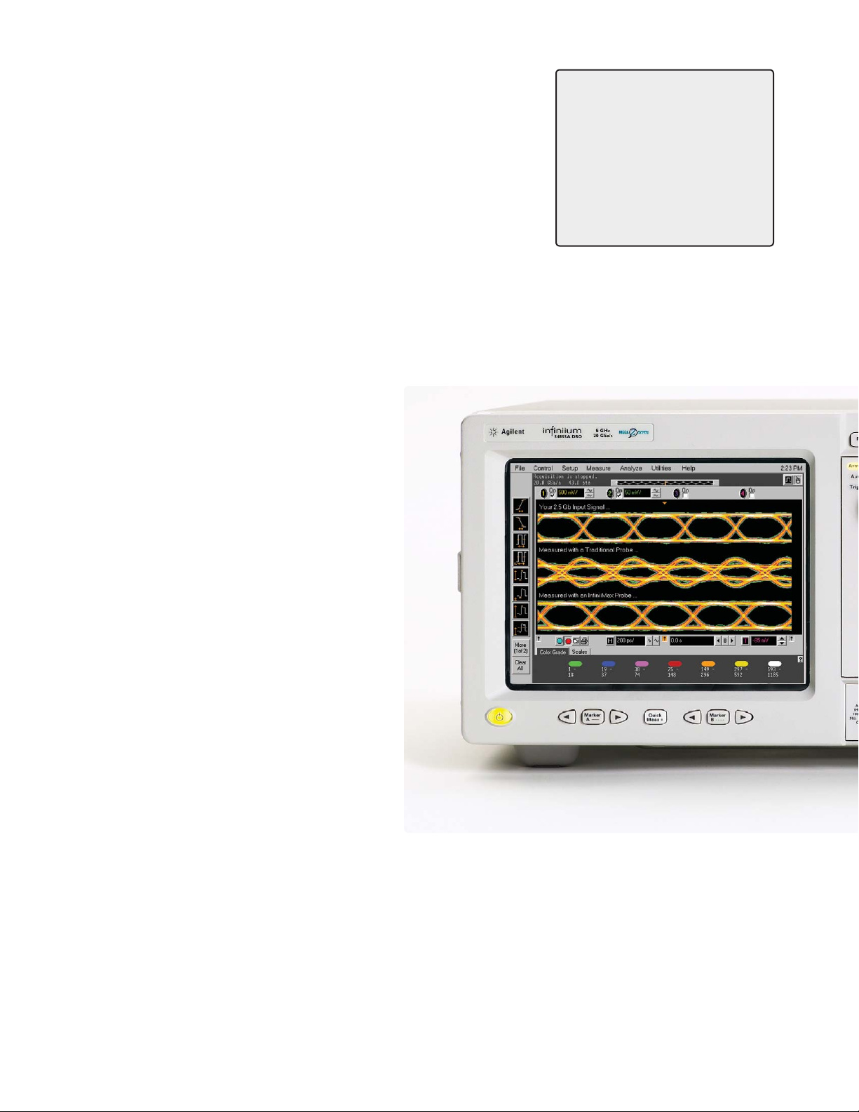
The highest-performance
end-to-end measurement
system available
If you are an experienced
scope user, you know that your
measurements are only as good
as your probing system. And
as bandwidth increases, it’s
increasingly important to ask
the question: am I measuring
my circuit or my scope probe?
Nothing is more frustrating than
chasing down an apparent design
problem, only to find that it was
caused by an inferior scope probe.
Together, the newest Agilent
Infiniium scopes and the
breakthrough Agilent InfiniiMax
InfiniiMax: The Worlds Best
High-Speed Probing System
EDN Magazine has awarded
Agilent’s InfiniiMax active probe
system the 2002 Innovation of the
Year Award.
high-performance probing
systems offer an end-to-end
measurement system with
unmatched performance,
accuracy, and connectivity. The
result is measurements you can
trust and better insight into your
circuit behavior.
Page 2

2
Benefits
54850 Series Infiniium oscilloscopes
Sample rate Standard acquisition Optional acquisition memory
Model Bandwidth Channels per channel memory
54855A 6 - 7 GHz 4 20 GSa/s 262 kpts per channel 1 Mpts per channel up to 20 GSa/s
32 Mpts per channel ≤ 2 GSa/s
54854A 4 GHz 4 20 GSa/s 262 kpts per channel 1 Mpts per channel up to 20 GSa/s
32 Mpts per channel ≤ 2 GSa/s
54853A 2.5 GHz 4 20 GSa/s 262 kpts per channel 1 Mpts per channel up to 20 GSa/s
32 Mpts per channel ≤ 2 GSa/s
54852A 2 GHz 4 10 GSa/s 262 kpts per channel 1 Mpts per channel up to 10 GSa/s
32 Mpts per channel ≤ 2 GSa/s
1130 Series InfiniiMax probe amplifier
Model Bandwidth Description
1134A 7 GHz Probe amplifier – order one or more probe heads or connectivity kits
1132A 5 GHz Probe amplifier – order one or more probe heads or connectivity kits
1131A 3.5 GHz Probe amplifier – order one or more probe heads or connectivity kits
1130A 1.5 GHz Probe amplifier – order one or more probe heads or connectivity kits
E2669A differential kit Each connectivity kit includes browser, solder-in and socket probe-heads
E2668A single-ended kit Each connectivity kit includes browser, solder-in and socket probe-heads
InfiniiMax probe amplifier specifications: Dynamic range = ± 2.5 V, DC offset range = ±12 V, maximum voltage = ± 30 V
1130 Series InfiniiMax probe system specifications (1134A probe amplifier with probe head)
Differential measurement Single-ended measurement
Probe head Model number (BW, input C, input R) (BW, input C, input R)
Differential solder-in E2677A 7 GHz, 0.27 pF, 50 kΩ 7 GHz, 0.44 pF, 25 kΩ
Differential socket E2678A 7 GHz, 0.34 pF, 50 kΩ 7 GHz, 0.56 pF, 25 kΩ
Differential browser E2675A 6 GHz, 0.32 pF, 50 kΩ 6 GHz, 0.57 pF, 25 kΩ
Differential SMA E2695A 7 GHz 7 GHz
Single-ended solder-in E2679A N/A 5.2 GHz, 0.50 pF, 25 kΩ
Single-ended browser E2676A N/A 5.5 GHz, 0.67 pF, 25 kΩ
Page 3

3
www.agilent.com/find/infiniimax
Key trends in the
electronics market
• Technologies with dramatically
increased clock speeds and
edge rates have emerged.
• Very fast serial differential
buses are being used to save
board space, reduce power and
provide better noise immunity.
• Densely packed circuit boards,
often with stacked daughter
boards, increase the need to
probe in very hard-to-reach
places.
Benefits (continued)
How much bandwidth and sample rate do I need?
Bandwidth required to measure risetime with 3% error Example: 100 ps rise time (20-80%)
Maximum signal frequency content = 0.4/rise time (20-80%) Maximum signal frequency = 4 GHz
Scope bandwidth required = 1.4 x maximum frequency Required scope bandwidth = 5.6 GHz
Minimum scope sample rate required = 2.5 x bandwidth Required scope sample rate = 14 GSa/s
Key benefits of the 54850 and
InfiniiMax Series
• Up to 7 GHz bandwidth can track
even the fastest signal speeds.
• A sample rate of 20 GSa/s on
all four channels can measure
high-speed differential buses
correlated with other signals.
• The innovative InfiniiMax
probing system supports even
the most demanding mechanical
access requirements without
sacrificing performance.
Page 4

4
20 GSa/s Sample Rate on All Channels at Once!
• The full real-time bandwidth of
up to 7 GHz is supported on
every channel by the 20 GSa/s
sample rate.
• This industry-leading sample
rate produces more accurate
and repeatable measurements,
avoiding measurement error
and signal aliasing due to under
sampling, as shown above.
• The combination of 7 GHz
bandwidth and 20 GSa/s
sample rate on all channels
makes the 54850 series ideal
for designs that include:
PCI-Express, Serial ATA,
Rapid IO, HyperTransport,
InfiniBand, or Gigabit Ethernet.
20 GSa/s provides accurate measurement.
10 GSa/s is not enough.
5 GSa/s is not enough.
Sample rate Measured rise time
20 GSa/s 89 psec
10 GSa/s 137 psec
5 GSa/s 238 psec
Example for 90 ps rise time input
Page 5

5
www.agilent.com/find/infiniimax
Application Software
E2690A Timing Interval and Jitter Analysis software
The Agilent E2690A Advanced Time Interval and
Jitter Analysis Software, licensed from Amherst
Systems Associates (ASA); offers the most powerful
and comprehensive set of tools for exploratory
debug of jitter, and it is remarkably easy to use.
The E2692A Basic Time Interval and Jitter Analysis
Software offers the basic tools you need for jitter
debug with the same precision you get with the
advanced version. Both advanced and basic
software versions provide complete jitter
decomposition into its components – including
deterministic, random, and total jitter – as well as
AutoMeasure to provide quick insight.
E2681A EZJIT Jitter analysis software
Includes the following key measurements:
cycle-to-cycle jitter, n-cycle jitter, period jitter,
time interval error, setup and hold time,
measurement histograms, measurement
trending, and jitter frequency spectrum.
N5400A EZJIT Plus Jitter
analysis software
Quickly separate random and deterministic jitter
components and estimate total jitter at low BER for
standards compliance. Automatic clock recovery
and pattern detection, an easy-to-use setup wizard
and graphical display views integrated into the
Infiniium oscilloscope software further simplify
navigation and RJ/DJ analysis.
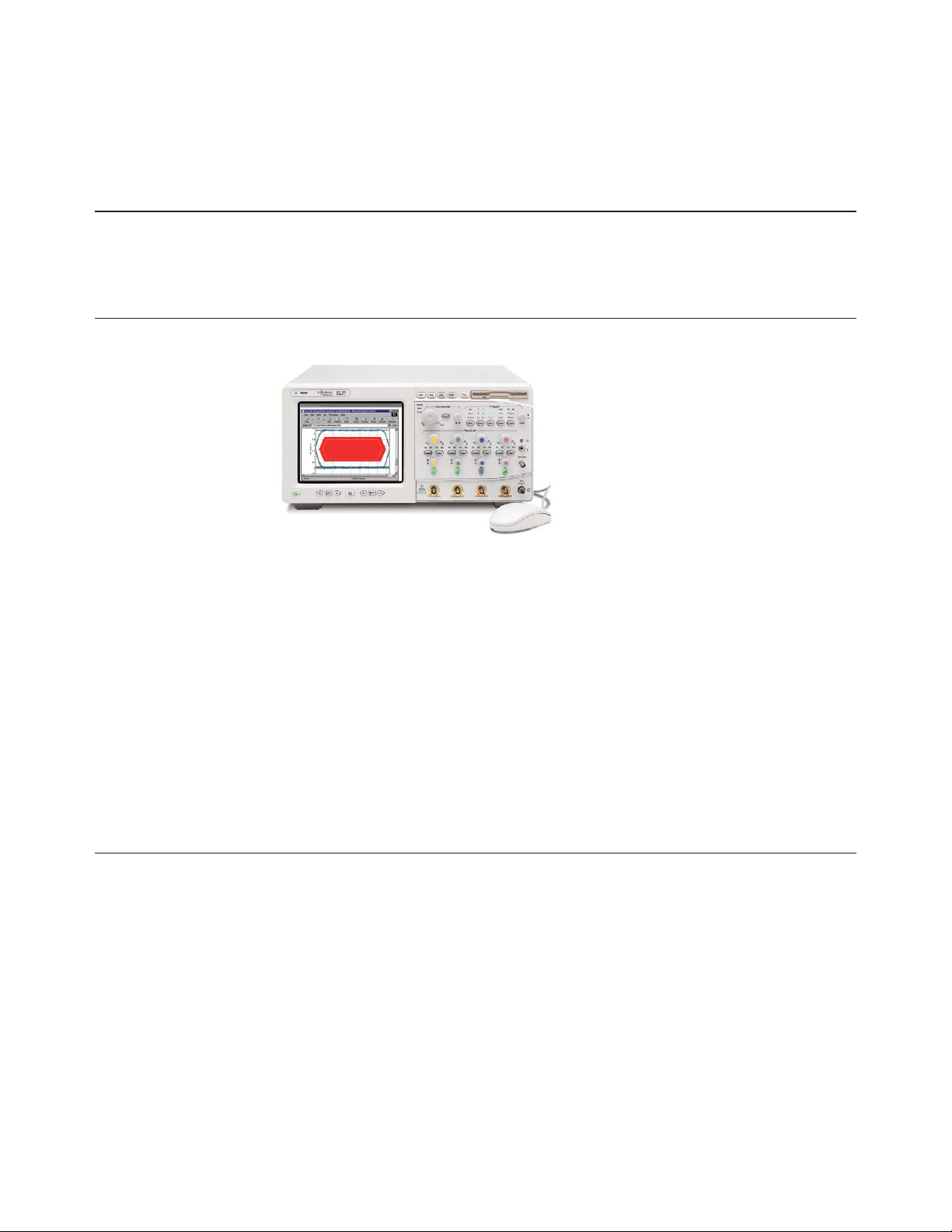
Page 6
6
Infiniium: “It’s like someone who sits down and actually uses
a scope designed this one.”
Steve Montgomery, Director of Engineering, Linx Technologies
20 GSa/s sample rate on all four channels
significantly reduces the chances of aliasing,
increases measurement accuracy, and delivers the
full real-time bandwidth of the oscilloscope on
every channel simultaneously.
Get fast answers to your questions with the builtin information system. Infiniium’s task-oriented
Setup Guide provides step-by-step instructions for
several advanced measurements and procedures.
See your signal more clearly with a large (8.4-inch)
high-resolution color display. Infiniium’s bright TFT
display with anti-glare coating lets you see the
details of your signal from all angles.
20 GB hard drive, 3.5” 1.44 MB floppy drive and
rear USB port make it easy to save setup files, data
files, screen shots, etc.
Identify anomalies easily with color-graded
persistence, a colorful visual representation of
waveform distribution.
Label waveforms and add notes to your screen
captures — Infiniium’s keyboard makes it easy.
Drag and drop markers with your mouse or use
the arrow keys.
Easy access to advanced features like math
functions and FFTs, is provided by the Windows-based
graphical user interface. This GUI also gives you
unique capabilities like drag-and-drop measurements
and zooming, and offers a graphical equivalent to all
front panel controls.
Remote access with Web-enabled connectivity,
e-mail on trigger, and GPIB over LAN allows you to
access your scope from remote locations.
32 Mpts acquisition memory at 2 GSa/s or slower
sample rates allows you to capture long time
windows at high resolution – such as identifying
glitches due to a power supply start-up from reset.
QuickMeas+ key gives you any five automated
measurements with a push of a button. You can
also configure this key to print/save screen shots,
save waveforms, or load a favorite setup.
Infiniium: Award-winning scopes
Infiniium has received eight industry
awards to date, including EDN’s
“Innovation of the Year” award
(twice) and T&M World’s “Best in
Test.” Agilent is committed to
breaking new ground and providing
tools that bring unique value to
our customers.
Page 7

Zoom and search with instant response. Zoom into
your signal using the horizontal scale knob and
search through your waveform with the position
knob. MegaZoom technology allows you to find
your area of interest quickly and easily – even with
32 Mpts waveforms.
Built-in CD-R drive on rear panel
allows you to update the system
software conveniently and can
be used to install third-party
application packages.
7
www.agilent.com/find/infiniimax
Hands-free operation with the Infiniium
VoiceControl option. Just speak into the
microphone to operate front-panel controls.
Segmented memory acquisition mode captures
bursting signals at maximum sample rate without
consuming memory during periods of inactivity.
Removable hard disk drive option is available for
added data security.
Install third-party software packages such as
Excel, LabView, Agilent Vee, MATLAB®, anti-virus
software, and more to perform customized
processing and automation of your oscilloscope or
to make the scope compliant to the network
environment of your company.
An external monitor allows you to run third-party
applications on a large, high-resolution display
while using the scope’s built-in monitor for
high-speed waveform display.
Windows®XP Pro operating system.
A familiar interface makes simple tasks simple.
Infiniium’s analog-like front panel has a full set
of controls color coded to the waveforms and
measurements, making simple tasks simple.
Three-year standard warranty and a variety of
Agilent support options protect your investment for
the long term.
A new 18 GHz, BNC-compatible connector
provides a high signal fidelity connection to Agilent
active probes, SMA adapters, and standard BNCs.
AutoProbe interface completely configures your
scope for use with the InfiniiMax probing system
and previous generation Agilent active probes.
10/100 Mbps LAN interface lets you easily print
waveforms on networked printers, save your results
on your office PC, share information with others,
and control the scope over the Web.
Page 8
8
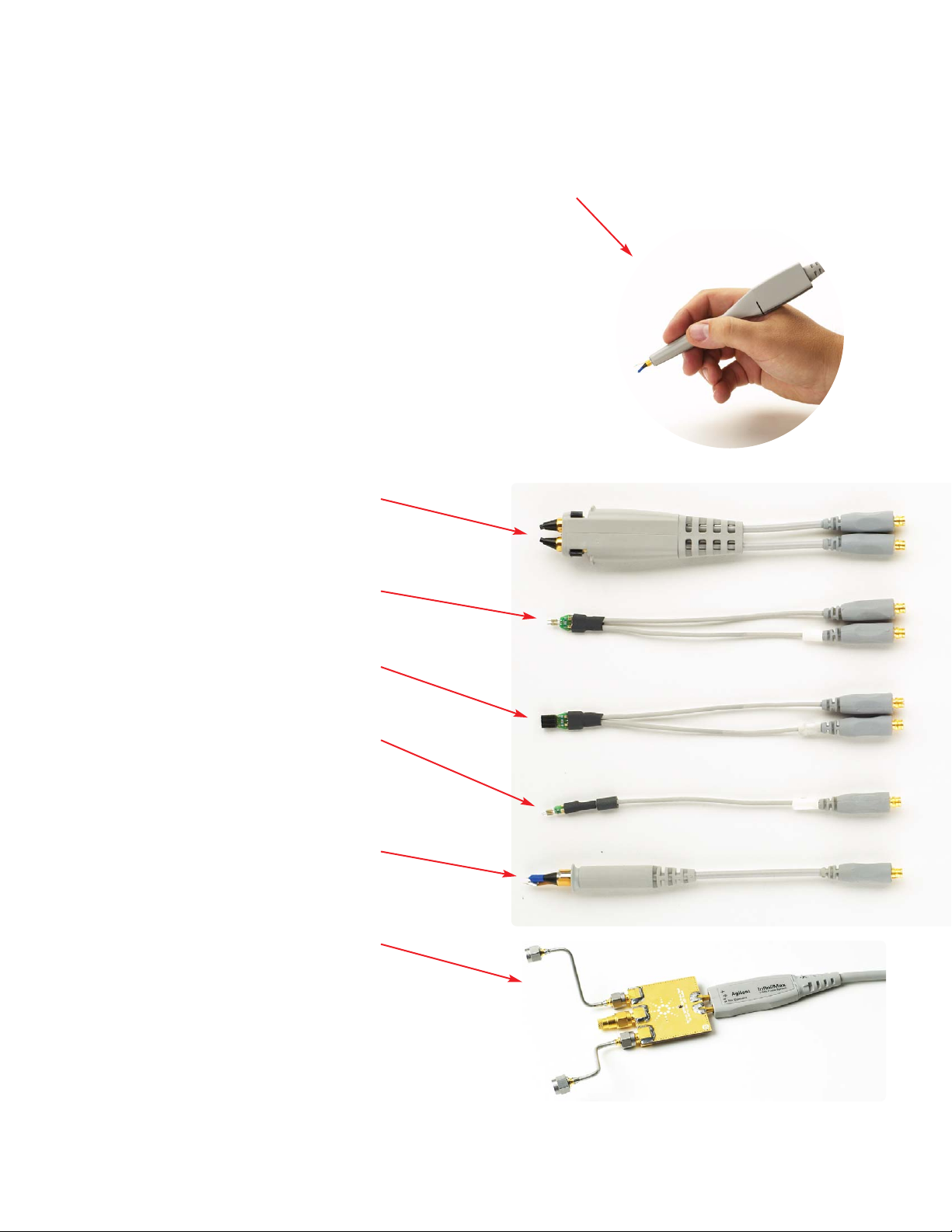
InfiniiMax: The Worlds Best High-Speed Probing System
InfiniiMax offers you the highest performance
available for measuring differential and
single-ended signals, with flexible connectivity
solutions for today’s high-density ICs and
circuit boards.
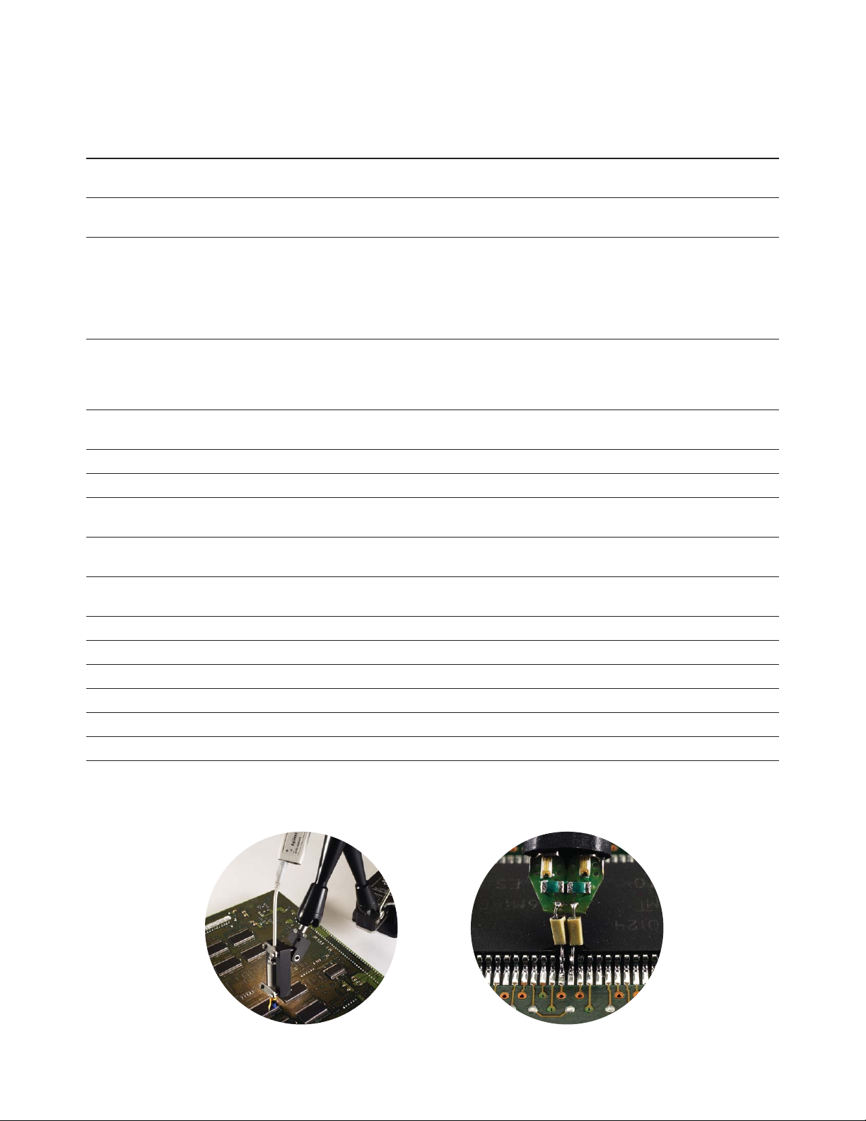
Variable spacing via the tab on the side of the
differential browser allows the probe tips to be
adjusted for different circuit geometries from
0.25-5.80 mm (10-230 mills).
Z-axis compliance allows both probe tips of the
differential browser to spring, supporting various
probing angles and target system characteristics.
Differential browser is the best choice for
general-purpose trouble-shooting of differential or
single-ended signals up to 6 GHz bandwidth.
Solder-in differential probe head provides 7 GHz
bandwidth and can be attached to very small
geometry circuits for measuring both single-ended
and differential signals.
The differential socket probe head can be used to
measure either differential or single-ended signals
to 7 GHz bandwidth.
Extremely small single-ended, solder-in probe
heads support 5.2 GHz measurements of even the
hardest-to-reach single-ended signals.
Single-ended browser is the best choice for
general purpose probing of single-ended signals
when small size of the probe head is the primary
consideration. Bandwidths up to 5.5 GHz can be
obtained in this configuration.
Differential SMA probe head provides 7 GHz
bandwidth and allows you to connect two SMA
cables to make a differential measurement on a
single scope channel.
The 54006A 7.5 GHz resistive divider probe is
available as a low-cost probing alternative for
casual inspection of signals.
A flat frequency response over the entire probe
bandwidth eliminates the distortion and
frequency-dependent loading effects that are
present in probes that have an in-band resonance.
Ergonomic sleeves make hand browsing
comfortable even over long periods of time.
Page 9

9
www.agilent.com/find/infiniimax
InfiniiMax is the world’s best high-speed probe
• InfiniiMax’s bandwidth is greater than the
scope’s bandwidth.
• Each use model (browsing, solder-in, socket) is
optimized for maximum performance.
• Supports both differential and single-ended
measurements with a single probe amplifier.
InfiniiMax probes have fully characterized
performance for all of their various probe heads.
This includes:
• Swept frequency response plot
• Common mode rejection vs. frequency plot
• Impedance vs. frequency plot
• Time-domain probe loading plot
• Time-domain probe tracking plot
See page 16 for an example.
One-year standard warranty on active probes and
a variety of Agilent support options to choose from.
Controlled impedance transmission lines in every
probe head deliver full performance versus the
performance limitations produced by traditional
wire accessories.
Probe interface software allows you to save the
calibration information for up to 10 different probe
heads per channel and will automatically retrieve
calibration data for a probe amplifier as it is
attached to the scope.
Supplied axial lead resistors, when trimmed to the
appropriate length, allow user to trade off bandwidth
and reach. Values and trimming templates are supplied
for measurements from 2.8 GHz to 7 GHz.
The damped-wire accessory provides maximum
connection reach and flexibility without introducing an
in-band resonance for signals up to 1.2 GHz bandwidth.
High-input impedance active probes minimize
loading, support differential measurements and DC
offset, and can compensate for cable loss.
EDN Magazine has awarded
Agilent’s InfiniiMax active probe
system the 2002 Innovation of the
year award. This exclusive award
program, now in its 13
th
year,
awards truly outstanding products
in the electronics industry.
Page 10

10
Infiniium 54850 Series Performance Characteristics
Vertical
Input channels 4
Analog bandwidth (–3 dB)* 54855A: 6 GHz 54854A: 4 GHz 54853A: 2.5 GHz 54852A: 2 GHz
Rise time (10% to 90%) 54855A: 70 ps 54854A: 105 ps 54853A: 168 ps 54852A: 210 ps
54855A with option 008: 62 ps
Input impedance 50 Ω ± 2.5%
Sensitivity
1
1 mV/div to 1 V/div
Input coupling DC
Vertical resolution
2
8 bits, ≥ 12 bits with averaging
Channel to channel isolation DC to 100 MHz: 40 dB
(any two channels with equal V/div settings) 100 MHz to 1 GHz: 28 dB
> 1 GHz to 6 GHz: 24dB
DC gain accuracy*
1
± 1% of full scale at full resolution channel scale
Maximum input voltage* ± 5 V
Offset range > ± 12 div or ± 4 Volts, whichever is smallest
Offset accuracy*
1
± (2% of channel offset + 1% of full scale)
Dynamic range ± 4 div from center screen
DC voltage measurement accuracy*
1
Dual cursor ± [(DC gain accuracy)+(resolution)]
Single cursor ± [(DC gain accuracy)+(offset accuracy)+(resolution/2)]
Horizontal
Main timebase range 54855A and 54854A: 5 ps/div to 20 s/div 54853A and 54852A: 10 ps/div to 20 s/div
Main timebase delay range –200 s to 200 s
Delayed timebase range 1 ps/div to current main time scale setting
Channel deskew –50 µs to 150 µs range, 100 fs resolution
Time scale accuracy
3
± 1 ppm pk
Delta-time measurement accuracy
6,7
≥ 256 Averages, rms 54855A: 70 fs rms 54854A: 90 fs rms 54853A: 110 fs rms 54852A: 160 fs rms
≥ 256 Averages, peak ± [ (0.5 ps) + (1 x 10
-6
x |reading|) ] peak
Averaging disabled, rms 54855A: 2.0 ps rms 54854A: 2.5 ps rms 54853A: 3.0 ps rms 54852A: 4.5 ps rms
Averaging disabled, peak ± [ (X ps) + (1 x 10
-6
x |reading|) ] peak
54855A: X = 7.0 ps 54854A: X = 8.0 ps 54853A: X = 10.0 ps 54852A: X = 15.0 ps
Jitter measurement floor
6
Time interval error 54855A: 1.4 ps rms 54854A: 1.8 ps rms 54853A: 2.0 ps rms 54852A: 3.0 ps rms
Period jitter 54855A: 2.0 ps rms 54854A: 2.5 ps rms 54853A: 3.0 ps rms 54852A: 4.5 ps rms
N-cycle, cycle-cycle jitter 54855A: 3.0 ps rms 54854A: 3.8 ps rms 54853A: 4.5 ps rms 54852A: 6.8 ps rms
Page 11

11
www.agilent.com/find/infiniimax
Infiniium 54850 Series Performance Characteristics (continued)
Acquisition
Real time sample rate per channel 54855A: 20 GSa/s 54854A: 20 GSa/s 54853A: 20 GSa/s 54852A: 10 GSa/s
Memory depth per channel
Standard 262,144 at all sample rates
Option 001 1,025,000 at all sample rates
32,800,000 ≤ 2 GSa/s sample rate
Sampling modes
Real time Successive single-shot acquisitions
Real time with averaging Selectable from 2 to 4096
Real time with peak detect 2 GSa/s peak detect, for less than 2 GSa/s sample rates (option 001 only)
Segmented memory Captures bursting signals at maximum sample rate without consuming memory
during periods of inactivity. Selectable number of segments up to 16,384 with
Option 001 deep memory installed. Minimum intersegment time (the time between
the end of the previous acquisition and the beginning of the next acquisition) of
20 µs. See on-line help for various performance points. The serial number breaks on
the 54850 Series models that support segmented memory are:
54852A: MY44000301 and greater
54853A: MY43001701 and greater
54854A: MY42001701 and greater
54855A: MY42001701 and greater
Filters
Sin(x)/x Interpolation On/off selectable FIR digital filter. Digital signal processing adds points between
acquired data points to enhance measurement accuracy and waveform display quality.
Trigger
Sensitivity
1
Internal Low
1
54855A: 0.5 div p-p 0 to 2 GHz, 1.0 div p-p 2 to 4 GHz, < 2.5 div @ 5 GHz
54854A: 0.5 div p-p 0 to 2 GHz, 1.0 div p-p 2 to 4 GHz
54853A: 0.5 div p-p 0 to 2 GHz, 1.0 div p-p 2 to 2.5 GHz
54852A: 0.5 div p-p 0 to 2 GHz
Internal High
1
54855A: 0.2 div p-p 0 to 6 GHz
54854A: 0.2 div p-p 0 to 4 GHz
54853A: 0.2 div p-p 0 to 2.5 GHz
54852A: 0.2 div p-p 0 to 2 GHz
Auxiliary DC to 500 MHz: 500 mV p-p
Level range
Internal ± 8 div from center screen or ± 4 Volts, whichever is smallest
Auxiliary ± 5 V
Sweep modes Auto, triggered, single
Trigger jitter
6,8
54855A: 1.0 ps rms 54854A: 1.3 ps rms 54853A: 1.7 ps rms 54852A: 1.8 ps rms
Trigger holdoff range 80 ns to 320 ms
Trigger actions Specify an action to occur and the frequency of the action when a trigger
condition occurs. Actions include e-mail on trigger and QuickMeas+.
Page 12

12
Infiniium 54850 Series Performance Characteristics (continued)
Trigger (continued)
Trigger modes
Edge Triggers on a specified slope and voltage level on any channel or auxiliary trigger.
Glitch Triggers on glitches narrower than the other pulses in your waveform by specifying
a width less than your narrowest pulse and a polarity. Triggers on glitches as narrow
as 500 ps. Glitch range settings: < 1.5 ns to < 160 ms.
Line Triggers on the line voltage powering the oscilloscope.
Pattern Triggers when a specified logical combination of the channels is entered, exited,
present for a specified period of time or is within a specified time range. Each
channel can have a value of High (H), Low (L) or Don’t care (X). Triggers on patterns
as narrow as 500 ps.
State Pattern trigger clocked by the rising or falling edge of one channel.
Logic type: AND or NAND.
Delay by time The trigger is qualified by an edge. After a specified time delay between 30 ns to
160 ms, a rising or falling edge on any one selected input will generate the trigger.
Delay by events The trigger is qualified by an edge. After a specified delay between 1 to 16,000,000
rising or falling edges, another rising or falling edge on any one selected input will
generate the trigger.
Violation triggers
Pulse width Trigger on a pulse that is wider or narrower than the other pulses in your waveform
by specifying a pulse width and a polarity. Triggers on pulse widths as narrow as
500 ps. Pulse width range settings: 1.5 ns to 160 ms.
Setup/hold Triggers on setup, hold or setup and hold violations in your circuit. Requires a clock
and data signal on any two input channels as trigger sources. High and low
thresholds and setup and/or hold time must then be specified.
Transition Trigger on pulse rising or falling edges that do not cross two voltage levels
in > or < the amount of time specified.
Measurements and math
Waveform measurements
Voltage Peak to peak, minimum, maximum, average, RMS, amplitude, base, top, overshoot,
preshoot, upper, middle, lower, area.
Time Period, frequency, positive width, negative width, duty cycle, delta time, rise time,
fall time, Tmin, Tmax, channel-to-channel phase.
Frequency domain FFT frequency, FFT magnitude, FFT delta frequency, FFT delta magnitude, FFT phase.
Statistics Displays the mean, standard deviation, minimum, maximum and number of
measurements value for the displayed automatic measurements.
Histograms Vertical (for timing and jitter measurements) or horizontal (noise and amplitude
change) modes, regions are defined using waveform markers. Measurements
included: mean, standard deviation, peak-to-peak value, median, min, max, total hits,
peak (area of most hits), and mean ± 1, 2, and 3 sigma.
Eye-diagram measurements Eye-diagram measurements include eye height, eye width, eye jitter, crossing
percentage, Q factor, and duty-cycle distortion.
Jitter analysis measurements Cycle-cycle jitter, N-cycle jitter, cycle-cycle + width, cycle-cycle – width,
(E2681A EZJIT or N5400A EZJIT Plus cycle-cycle duty cycle, data rate, unit interval, time interval error data,
Jitter Analysis software) time interval error clock, setup time, hold time, phase, period, frequency, + width,
– width, duty cycle, rise time, fall time.
Page 13

13
www.agilent.com/find/infiniimax
Infiniium 54850 Series Performance Characteristics (continued)
Measurements and math (continued)
Mask testing Allows pass/fail testing to user-defined or Agilent-supplied waveform templates.
AutoMask lets you create a mask template from a captured waveform and define a
tolerance range in time/voltage or percentage. Test modes include test forever, test
to specified time or event limit, and stop on failure. Communications Mask Test Kit
option provides a set of ITU-T G.703, ANSI T1.102, and IEEE 802.3 industry-standard
masks for compliance testing.
Waveform math Four functions, select from add, average, differentiate, divide, FFT magnitude,
FFT phase, integrate, invert, magnify, min, max, multiply, subtract, versus,
common mode, smoothing.
FFT
Frequency range
4
DC to 10 GHz.
Frequency resolution Sample rate/memory depth = Resolution.
Best resolution at maximum sample rate 54855A, 54854A, 54853A: 20 GSa/s / 1 Mpts = 20 kHz.
54852A: 10 GSa/s / 1 Mpts = 10 kHz.
Frequency accuracy (1/2 frequency resolution)+(1 x 10
-6
)(signal frequency).
Signal-to-noise ratio
5
60 dB at 32k memory depth.
Window modes Hanning, flattop, rectangular.
Measurement modes
Automatic measurements Measure menu access to all measurements, five measurements can be
displayed simultaneously.
QuickMeas+ Front-panel button activates five pre-selected or five user-defined automatic
measurements.
Drag-and-drop measurement toolbar Measurement toolbar with common measurement icons that can be dragged
and dropped onto the displayed waveforms.
Marker modes Manual markers, track waveform data, track measurements.
Display
Display
Display 8.4 inch diagonal color TFT-LCD.
Resolution 640 pixels horizontally x 480 pixels vertically.
Annotation Up to 12 labels, with up to 100 characters each, can be inserted into the waveform area.
Grids Can display 1, 2 or 4 waveform grids.
Waveform styles Connected dots, dots, persistence (minimum, variable, infinite), color-graded
infinite persistence.
Computer system and peripherals, I/O ports
Computer system and peripherals
Operating system Windows
®
XP Pro.
CPU Intel
®
Pentium®III 1 GHz microprocessor.
PC system memory 512 MB.
Drives ≥ 20 GB internal hard drive, CD-R drive on rear panel, standard 3.5 inch
1.44 MB floppy drive.
Peripherals Logitech optical USB mouse and compact keyboard supplied. All Infiniium models
support any Windows-compatible input device with a serial, PS/2 or USB interface.
File types
Waveforms Compressed internal format, comma and tab separated X and Y pairs or voltage values.
Images BMP, PCX, TIFF, GIF or JPEG.
Page 14

14
Infiniium 54850 Series Performance Characteristics (continued)
Computer system and peripherals, I/O ports (continued)
I/O ports
LAN RJ-45 connector, supports 10Base-T and 100Base-T. Enables Web-enabled remote
control, e-mail on trigger or demand, data/file transfers and network printing.
GPIB IEEE 488.2, fully programmable.
RS-232 (serial) COM1, printer and pointing device support.
Parallel Centronics printer port.
PS/2 2 ports. Supports PS/2 pointing and input devices.
USB 2 ports. Allows connection of USB peripherals like storage devices and
pointing devices while the oscilloscope is on.
Video output 15 pin VGA, full color output of scope waveform display.
Dual-monitor video output 15 pin XGA, full color output for using third-party applications.
Auxiliary output DC (±2.4 V); square wave (~715 Hz and 456 MHz); trigger output
(255 mV p-p into 50 Ω).
Trigger output 5 V 50 Ω back-terminated.
Time base reference output 10 MHz, 5V 50Ω back-terminated.
General characteristics
Temperature Operating: 5° C to +40° C.
Non-operating: –40° C to +70° C.
Humidity Operating: Up to 95% relative humidity (non-condensing) at +40°C.
Non-operating: Up to 90% relative humidity at +65°C.
Altitude Operating: Up to 4,600 meters (15,000 feet).
Non-operating: Up to 15,300 meters (50,000 feet).
Vibration Operating: Random vibration 5-500 Hz, 10 minutes per axis, 0.3 g(rms).
Non-operating: Random vibration 5-500 Hz, 10 minutes per axis, 2.41 g(rms);
resonant search 5-500 Hz, swept sine, 1 octave/minute sweep rate, (0.75g),
5 minute resonant dwell at 4 resonances per axis.
Power 100-240 VAC, ± 10%, Cat II, 47 to 440 Hz; max power dissipated: 475 W.
Weight Net: 13 kg (28.5 lbs.).
Shipping: 16 kg (35.2 lbs.).
Dimensions (excluding handle) Height: 216 mm (8.5 in).
Width: 437 mm (17.19 in).
Depth: 440 mm (17.34 in).
Safety Meets IEC 61010-1 +A2, CSA certified to C22.2 No.1010.1, self-certified to UL 3111.
* Denotes warranted specifications, all others are typical. Specifications are valid after a 30-minute warm-up period, and ±5°C from annual calibration temperature.
1 Full scale is defined as 8 vertical divisions. Vertical divisions are defined by the major scale settings above non-major scale settings. The major scale settings are 10 mV, 20 mV,
50 mV, 100 mV, 200 mV, 500 mV, 1 V.
2 Vertical resolution for 8 bits = 0.4% of full scale, for 12 bits = 0.024% of full scale.
3 Within one year of previous calibration.
4 FFT amplitude readings are affected by input amplifier roll-off.
54855A: –3 dB at 6 GHz, with amplitude decreasing as frequency increases above 6 GHz.
54854A: –3 dB at 4 GHz, with amplitude decreasing as frequency increases above 4 GHz.
54853A: –3 dB at 2.5 GHz, with amplitude decreasing as frequency increases above 2.5 GHz.
54852A: –3 dB at 2 GHz, with amplitude decreasing as frequency increases above 2 GHz.
5 The noise floor varies with memory depth and averaging.
6 Test signal peak-to-peak amplitude ≥ 5 divisions; vertical scale ≥ 10 mV/div; test signal rise time ≤ 415 ps (54852A), 335 ps (54853A), 225 ps (54854A), 150 ps (54855A);
sample rate = 20 GSa/s (10 GSa/s for 54852A); sin(x)/x interpolation enabled; measurement threshold = fixed voltage at 50 % level.
7 Between two edges on a single channel. Rms value refers to the standard deviation of 256 consecutive measurements performed using an individual instrument.
8 Internal trigger. Trigger level contained within full scale display range of trigger channel.
Page 15
15
www.agilent.com/find/infiniimax
InfiniiMax 1130 Series Performance Characteristics
1134A, 1132A, 1131A, 1130A
Bandwidth* 1134A: > 7 GHz 1131A: > 3.5 GHz
1132A: > 5 GHz 1130A: > 1.5 GHz
Rise and fall time (10% to 90%) 1134A: 60 ps 1131A: 100 ps
1132A: 86 ps 1130A: 233 ps
System bandwidth (–3 dB) 1134A with 54855A: 6 GHz
1132A with 54854A: 4 GHz
1131A with 54853A: 2.5 GHz
1131A with 54846B: 2.25 GHz
1131A with 54852A: 2 GHz
1130A with 54832B/D, 33A/D: 1 GHz
Input capacitance
1
Cm = 0.10 pF Cm is between tips
Cg = 0.34 pF Cg is to ground for each tip
Cdiff = 0.27 pF Differential mode capacitance = Cm + Cg/2
Cse = 0.44 pF Single-ended mode capacitance = Cm + Cg
Input resistance* Differential mode resistance = 50 kΩ ±2%
Single-ended mode resistance = 25 kΩ ±2%
Input dynamic range 5.0 V peak to peak, ± 2.5 V
Input common mode range 6.75 V peak to peak dc to 100 Hz; 1.25 V peak to peak > 100 Hz
Maximum signal slew rate 18 V/ns when probing a single-ended signal
30 V/ns when probing a differential signal
DC attenuation 10:1 ± 3% before calibration on oscilloscope
10:1 ± 1% after calibration on oscilloscope
Zero offset error referred to input < 30 mV before calibration on oscilloscope
< 5 mV after calibration on oscilloscope
Offset range ± 12.0 V when probing single-ended
Offset accuracy < ± 1% of setting when probing single-ended
Noise referred to input 3.0 mV rms
Propagation delay ~6 ns (this delay can be deskewed relative to other signals)
Maximum input voltage 30 V peak, CAT I
ESD tolerance > 8 kV from 100 pF, 300 Ω HBM
* Denotes warranted specifications, all others are typical.
1 Measured using the probe amplifier and solder-in differential probe head with full bandwidth resistors.
Page 16

16
InfiniiMax 1130 Series Performance Characteristics (continued)
The electrical properties of the oscilloscope’s probe
head or probe accessory can often be the limiting
factor in the measurement bandwidth or
measurement accuracy that can be realized in
practical use. The InfiniiMax probing system is the
only high-bandwidth probing system that provides
characterized performance plots for each of its
probe heads. This allows you to see the measurement
capability you can achieve for a given use model.
Additional InfiniiMax probe information including
input impedance SPICE models (and corresponding
SPICE decks) for InfiniiMax probes can be found
online at www.cos.agilent.com/manuals/scopes.html.
Example of characterized performance plots: differential solder-in probe head
Swept frequency response
Common mode rejection vs. frequency
Time-domain probe loading
Time-domain probe tracking of 100 ps 10-90% step
Impedance vs. frequency
Single-Ended
Mode Input
Differential Mode Input
Vin
tr = 116 ps
Vsource
tr=98 ps
Vin
tr = 116 ps
Vout
tr = 121 ps
Vout / Vin
Vout
Vin
8 GHz 3dB bandwidth (typical)
50 kΩ
25 kΩ
0.44 pF
0.27 pF
Zmin = 201.7 Ω
Zmin = 272.4 Ω
6
3
0
dB
-3
-6
-9
-12
8
10
0.2
0.15
0.1
Volts
0.05
0
-0.05
0.20 0.4 0.6 0.8 1 1.2 1.4 1.6 1.8 2
9
10
Frequency (Hz)
Time (Seconds)
10
0
dB
-10
-20
-30
-40
-50
-60
8
10
9
10
Frequency (Hz)
10
10
10
0.2
0.15
Time (Seconds)
x 10
-9
x 10
0.1
Volts
0.05
0
-0.05
-9
0.20 0.4 0.6 0.8 1 1.2 1.4 1.6 1.8 2
5
10
10
10
Ohms
10
10
4
3
2
1
6
10
7
10
Frequency (Hz)
8
10
9
10
10
10
Page 17

17
www.agilent.com/find/infiniimax
54850 Series Infiniium oscilloscopes
Model Bandwidth Channels Sample rate per channel Standard acquisition memory
54855A 6 - 7 GHz 4 20 GSa/s 262 kpts per channel
54854A 4 GHz 4 20 GSa/s 262 kpts per channel
54853A 2.5 GHz 4 20 GSa/s 262 kpts per channel
54852A 2 GHz 4 10 GSa/s 262 kpts per channel
The above models include:
• Optical USB mouse
• Compact keyboard
• User's quick-start guide
• Documentation CD (service guide, programmer’s guide, programmer’s quick reference guide)
• Accessory pouch
• Power cord
• High-performance calibration cable (54855A only)
• E2655B probe deskew and performance verification kit
• Two 54855-67604 BNC-compatible to precision 3.5 mm (f) adapters (54855A, 54854A only)
• Three-year warranty.
Note: No probes are included with the 54850 Series oscilloscopes. The InfiniiMax 1130 Series probes must be purchased separately.
Ordering Information
Page 18

18
Ordering Information (continued)
54850 Series Infiniium oscilloscope options and accessories
Options Description
001 1M/ch memory upgrade for Infiniium 5485xA oscilloscopes
(32M/ch for sample rates ≤ 2 GSa/s).
002 EZJIT jitter analysis software for Infiniium 5485xA oscilloscopes (installed at the factory).
003 High-Speed Serial Data Analysis/Mask Testing with clock recovery and
8b/10b decoding (installed at the factory).
004 EZJIT Plus jitter analysis software (installed at the factory).
006 My Infiniium Integration Package (installed at the factory).
008 7 GHz enhanced bandwidth software for the 54855A oscilloscope. Increase measurement
bandwidth to 7 GHz (typical) or reduce scope bandwidth to 1 GHz to reduce system noise.
017 20 GB removable hard disk drive for Infiniium 5485xA oscilloscopes
Replaces internal hard disk with a removable hard disk. Order the N5390A for additional
hard disk drive cartridges.
021 Low-Speed Serial Data Analysis for Infiniium 548xx oscilloscopes (installed at the factory).
Instrument options Description
1CM (E2609B) Rack-mount kit.
Service options Description
A6J ANSI Z540-compliant calibration.
Accessories Description
E2680A After-purchase memory upgrade for Infiniium 5485xA oscilloscopes.
Order 5485xA option 001 when purchasing a new Infiniium 5485xA oscilloscope. The E2680A
is for customers who own a 5485xA scope and wish to upgrade the acquisition memory.
E2681A After-purchase EZJIT jitter analysis software for Infiniium 5485xA oscilloscopes.
Order 5485xA option 002 when purchasing a new Infiniium 5485xA oscilloscope. The E2681A is
for customers who own a 5485xA oscilloscope and wish to upgrade to add the EZJIT software.
N5400A After-purchase EZJIT Plus jitter analysis software for Infiniium oscilloscopes.
The N5400A is for customers who own a 54850 or DSO80000 Series oscilloscope and
wish to upgrade to add the EZJIT Plus software.
N5401A After-purchase EZJIT Plus jitter analysis software for existing installations of E2681A
EZJIT on Infiniium 54850 and DSO80000 Series Infiniium oscilloscopes. Adds RJ/DJ
separation displays and analysis capability.
E2690A After-purchase Advanced Timing Interval and Jitter Analysis software for Infiniium
5485xA oscilloscopes. Available in one scope license and four scope license versions.
N5390A Additional 20 GB hard disk drive cartridge for Infiniium 5485xA option 017
E2654A EZ Probe Positioner®: includes base, joystick, and articulating arm.
Page 19

19
www.agilent.com/find/infiniimax
54850 Series Infiniium oscilloscope options and accessories (continued)
Accessories (continued) Description
E2655B Additional probe deskew/performance verification kit for InfiniiMax probes.
54855-67604 18 GHz BNC-compatible to precision 3.5 mm (f) adapter for Infiniium 5485xA scopes.
Allows highest fidelity connection of 3.5 mm or SMA cables.
E2688A High-Speed Serial Data Analysis/Mask Testing with Clock Recovery.
Easily perform mask testing and characterize serial data streams that employ embedded
clocks. The E2688A provides mask templates and clock recovery for verifying compliance to
computer, communication and datacom standards. You can even characterize proprietary
serial buses with the built-in, general purpose golden PLL clock recovery.
Features include:
• Golden PLL clock recovery
• Set up wizard to configure the clock recovery
• Real-time eye diagram display with eye-mask unfolding
• Recovered clock display
• Time interval error (TIE) jitter measurement with statistics on the data stream
• Mask template loading
• 8b/10b decode with symbol trigger and search
Standard masks include:
• PCI Express (2.5 Gbps)
• Serial ATA (1.5 Gbps)
• Fibre Channel Electrical (1.0625, 2.125, 4.25 Gbps)
• Ethernet IEEE 802.3 (10/100/1000Base-T)
• Serial Attached SCSI, XAUI
89601A Vector Signal Analysis Software.
Agilent Infiniium oscilloscopes team up with the 89601A Vector Signal Analysis software
to provide powerful, flexible, wideband signal analysis with up to 13 GHz bandwidth for
applications including wideband communications and modulated radar.
Features include:
• Measurement bandwidth up to 13 GHz
• Flexible analog and digital demodulation supports the most advanced, complex modulation formats
• Deep memory in the Infiniium oscilloscopes allows excellent dynamic range and frequency resolution
• Flexible, powerful displays including spectrogram provide rapid insight into dynamic signal behavior
• For signal integrity and jitter measurements up to 13-GHz bandwidth the high performance Infiniium
54850 or 80000 Series digital oscilloscopes offer InfiniiMax active probes, MegaZoom deep memory,
and 40 GSa/s sample rates
Ordering Information (continued)
Page 20

20
Ordering Information (continued)
54850 Series Infiniium oscilloscope options and accessories (continued)
Accessories (continued) Description
N5392A Ethernet Electrical Performance Validation and Compliance Software for
Infiniium 54830, 54850, and 80000 Series Oscilloscopes.
The Agilent Technologies N5392A Ethernet electrical performance validation and compliance
software for Infiniium 54830, 54850 and 80000 Series oscilloscopes provides you with a
fast and easy way to verify and debug your 1000Base-T, 100Base-TX and 10Base-T Ethernet
designs. The Ethernet electrical test software allows you to automatically execute Ethernet
physical-layer (PHY) electrical tests, and it displays the results in a flexible report format. In
addition to the measurement data, the report provides a margin analysis that shows how
closely your device passed or failed each test.
The Ethernet electrical performance validation and compliance software performs a wide range
of electrical tests to meet the Ethernet electrical specifications for 1000Base-T, 100Base-TX and
10Base-T systems as documented in the IEEE 802.3-2002 and ANSI X3.263-1995 standards.
Features:
• Test setup wizard guides you through test selection, configuration, connection, execution,
and results reporting.
• Wide-range of electrical tests are performed for 1000Base-T, 100Base-TX and 10Base-T standards.
• Measurement connection setups are displayed when you must change the test setup.
• Oscilloscope setup is automatically configured for each test.
• Test results report formally documents your test configuration, measurements made,
pass/fail status, and waveforms.
• Pass/fail margin analysis provides an indication of how close your device is to meeting a
test specification.
N5393A PCI Express Electrical Performance Validation and Compliance Software.
The Agilent Technologies N5393A PCI Express electrical performance validation and
compliance software provides you with a fast and easy way to verify and debug your PCI
Express designs. The PCI Express electrical test software allows you to automatically execute
PCI Express electrical checklist tests, and it displays the results in a flexible report format.
The N5393A PCI Express electrical test software utilizes the clock recovery method used in the
official PCI-SIG Signal Quality Test Methodology (“SigTest”) application, ensuring that your test
results are consistent with results from the SigTest application.
The PCI Express electrical performance validation and compliance software performs a wide
range of electrical tests as per the PCI Express 1.0a electrical specifications for add-in cards
and motherboard systems as documented in section 4 of the base specification and section 4
of the card electromechanical specification.
Requires the E2688A serial data analysis software and one of the PCI-SIG approved compliance
test fixtures (CBB or CLB).
Features:
• Test setup wizard guides you through test selection, configuration, connection, execution,
and results reporting.
• Wide-range of electrical tests are performed, significantly more than SigTest.
• PCI-SIG SigTest clock recovery algorithm is used to ensure consistency with SigTest.
• Measurement connection setups are displayed when you must change the test setup.
• Oscilloscope setup is automatically configured for each test.
• Test results report formally documents your test configuration, measurements made,
pass/fail status, and waveforms.
• Pass/fail margin analysis provides an indication of how close your device is to meeting a
test specification.
Page 21

21
www.agilent.com/find/infiniimax
Ordering Information (continued)
54850 Series Infiniium oscilloscope options and accessories (continued)
Accessories (continued) Description
N5394A DVI Electrical Performance Validation and Compliance Software for
Infiniium 54850 and 80000 Series Oscilloscope.
The Agilent Technologies N5394A DVI electrical performance validation and compliance
software provides you with a fast and easy way to verify and debug your digital visual interface
(DVI) designs for add-in cards, cables and motherboard systems. The DVI electrical test
software allows you to automatically execute DVI electrical checklist tests, and it displays the
results in a flexible report format. In addition to the measurement data, the report provides a
margin analysis that shows how closely your device passed or failed each test.
The N5394A DVI electrical performance validation and compliance software offers the four
fundamental DVI electrical tests. The software automatically configures the oscilloscope for
each test, and it provides an informative results report that includes margin analysis indicating
how close your product is to passing or failing that specification.
Features:
• Test setup wizard guides you through test selection, configuration, connection, execution,
and results reporting.
• Wide-range of electrical tests are performed.
• Uses the Silicon Graphics DVI Compliance test fixtures for measurements and hardware
clock recovery.
• Measurement connection setups are displayed when you must change the test setup.
• Oscilloscope setup is automatically configured for each test.
• Test results report formally documents your test configuration, measurements made,
pass/fail status, and waveforms.
• Pass/fail margin analysis provides an indication of how close your device is to meeting a
test specification.
Download Serial ATA Signal Quality Compliance Test.
If you develop Serial ATA host bus adapters or devices and would like to perform
compliance testing to the standard, the sigtest program provides the following features:
• program runs inside Infiniium 54855A and tests host bus adapters and devices for
compliance to Serial ATA standard, as issued by Serial ATA working group
• written test procedure for Agilent Infiniium 54855A and Agilent 81134A pulse/pattern generator
• software automatically sets up the oscilloscope, allows user to transfer setups to pattern
generator, acquires waveform data and launches eye measurement (sigtest)
• includes support for OOB (out of band) signal testing
• solution has been evaluated and proven at Serial ATA plugfests
Program can be downloaded for free from the following URL:
http://www.cos.agilent.com/scope-apps/sata.html
Page 22
22
54850 Series Infiniium oscilloscope options and accessories (continued)
Accessories (continued) Description
Partner Product IEEE-1394 Pre-Compliance Test Option.
A pre-compliance test solution is available from Quantum Parametrics for use
in conjunction with Agilent 54850 Series oscilloscopes. This test solution
automates the compliance test process for the IEEE-1394 standard.
See http://www.quantumparametrics.com for additional information.
E2683A USB 2.0 Compliance Test Option.
The Agilent USB 2.0 compliance test option makes USB signal integrity testing as simple as
capturing the signals with your oscilloscope. Infiniium has significantly reduced the work
associated with USB compliance testing by eliminating the need to transfer scope waveforms
to a PC. The Infiniium USB 2.0 test option features run-time MATLAB embedded in the scope for
use with the USB signal integrity scripts, providing a one-box solution. The USB-IF compliance
program recognizes Infiniium as a recommended scope for use in pre-compliance testing. In addition,
all MATLAB scripts used with the USB 2.0 test option come from the USB-IF organization.
This option works with all Infiniium 5485xA 4-channel oscilloscopes. Included with the E2683A
are USB-IF MATLAB scripts and Signal Quality Inrush Droop/Drop (SqiDD) test fixture, needed
for low/full speed testing. Additional SqiDD test fixtures can be purchased as the E2646A.
For USB 2.0 High Speed testing, order the E2683A test option as well as the E2649A for a
complete set of six fixtures and power supply.
For USB 2.0 High Speed testing, a differential probe is required. Please order either the
InfiniiMax 1130A 1.5 GHz, 1131A 3.5 GHz, 1132A 5 GHz or 1134A 7 GHz probe amplifiers, along
with the E2669A differential connectivity kit or E2678A differential socketed probe head.
The USB 2.0 Compliance Test Procedure is located at http://www.usb.org/developers/docs
Ordering Information (continued)
Page 23

23
www.agilent.com/find/infiniimax
Ordering Information (continued)
54850 Series Infiniium oscilloscope options and accessories (continued)
Accessories (continued) Description
E2697A High Impedance Adapter (Includes 500 MHz Passive Probe)
for Infiniium 54850 Series Oscilloscopes.
The E2697A high impedance adapter allows
connection of probes that require a high impedance
input (e.g., passive probes, current probes) to the
Infiniium 54855A, 54854A, 54853A and 54852A family
of high performance oscilloscopes. The E2697A high
impedance adapter extends the capability of Agilent
Infiniium high-performance oscilloscopes, making them
ideal for a variety of general-purpose measurements such
as power supplies, inverters, semiconductor measurements,
etc. The E2697A provides switchable ac/dc coupling, as
well as 10:1 and 1:1 attenuation settings.
Specifications/Characteristics
Bandwidth Analog BW (-3 dB)* 500 MHz (with supplied 10073C passive probe)
System Bandwidth 500 MHz (with 10073C passive probe and
54850 series oscilloscope)
Dc attenuation 1.16:1 E2697A internal attenuator at 1:1 (at scale settings > 200 mV/div
signal size limited by input dynamic range)
11.6:1 E2697A internal attenuator at 10:1 (at scale settings > 200 mV/div
signal size limited by input dynamic range)
Input Dynamic Range E2697A internal attenuator setting of 1:1 ±0.8 V
E2697A internal attenuator setting of 10:1 ±8 V
Input Dynamic Range with E2697A internal attenuator setting of 1:1 ±8 V
10073C passive probe E2697A internal attenuator setting of 10:1 ±80 V
Input Impedance* 1 MΩ ± 1% (~12 pF)
Input Coupling dc, ac (7 Hz)
Maximum Input Voltage ±100V [dc + ac] [ac < 10 kHz], CAT I
Offset Range E2697A internal attenuator setting of 1:1 ±5 V
E2697A internal attenuator setting of 10:1 ±50 V
Dc Gain Accuracy*
1
±1.5% of full scale
Offset Accuracy *
1
±(1.5% of channel offset +1.5% of full scale)
* Denotes warranted specifications, all others typical. Specifications are valid after a 30 minute warm-up period and ±5 °C from
calibration temperature.
1 Full scale is defined as 8 vertical divisions.
Page 24

24
Ordering Information (continued)
54850 Series Infiniium oscilloscope options and accessories (continued)
Accessories (continued) Description
E2625A Communication Mask Test Kit.
Take the frustration out of communications testing and prove your designs conform to industry
standards with the E2625A Communications Mask Test Kit option. Infiniium’s familiar Windows
interface makes it easy for you to access the masks you need and configure your tests.
In addition, the E2625A Communication Mask Test Kit comes with a set of electrical communication
adapters to ensure convenient, reliable and accurate connections to your device under test. Included
are more than 20 industry standard ANSI T1.102 and ITU-T G.703 communication signal mask templates.
E5850A Logic Analyzer/Oscilloscope Time-Correlation Fixture.
Now you can more effectively verify and track down problems between the analog and digital
portions of a design. Easily make time-correlated measurements between an Agilent 16700 Series
logic analysis system and an Infiniium 54800 Series oscilloscope. With the E5850A Time-Correlation
Fixture, you can trigger the Infiniium from the logic analyzer (or vice versa), automatically deskew
the waveforms and simultaneously view the Infiniium oscilloscope waveforms and the logic
analyzer’s timing waveforms on your Agilent 16700 Series Logic Analyzer.
Foot Switch Kinesis Savant 3-Action Programmable Foot Switch P/N FS004PS2.
Allows you to easily program the 3-action foot pedals to perform the following
scope functions: run, stop, toggle between run and stop, save waveform, save
screenshot, measure any five waveform parameters and recall an instrument setup.
See http://www.kinesis-ergo.com for additional information and ordering instructions.
Page 25
25
www.agilent.com/find/infiniimax
Ordering Information (continued)
54850 Series Infiniium oscilloscope options and accessories (continued)
Accessories (continued) Description
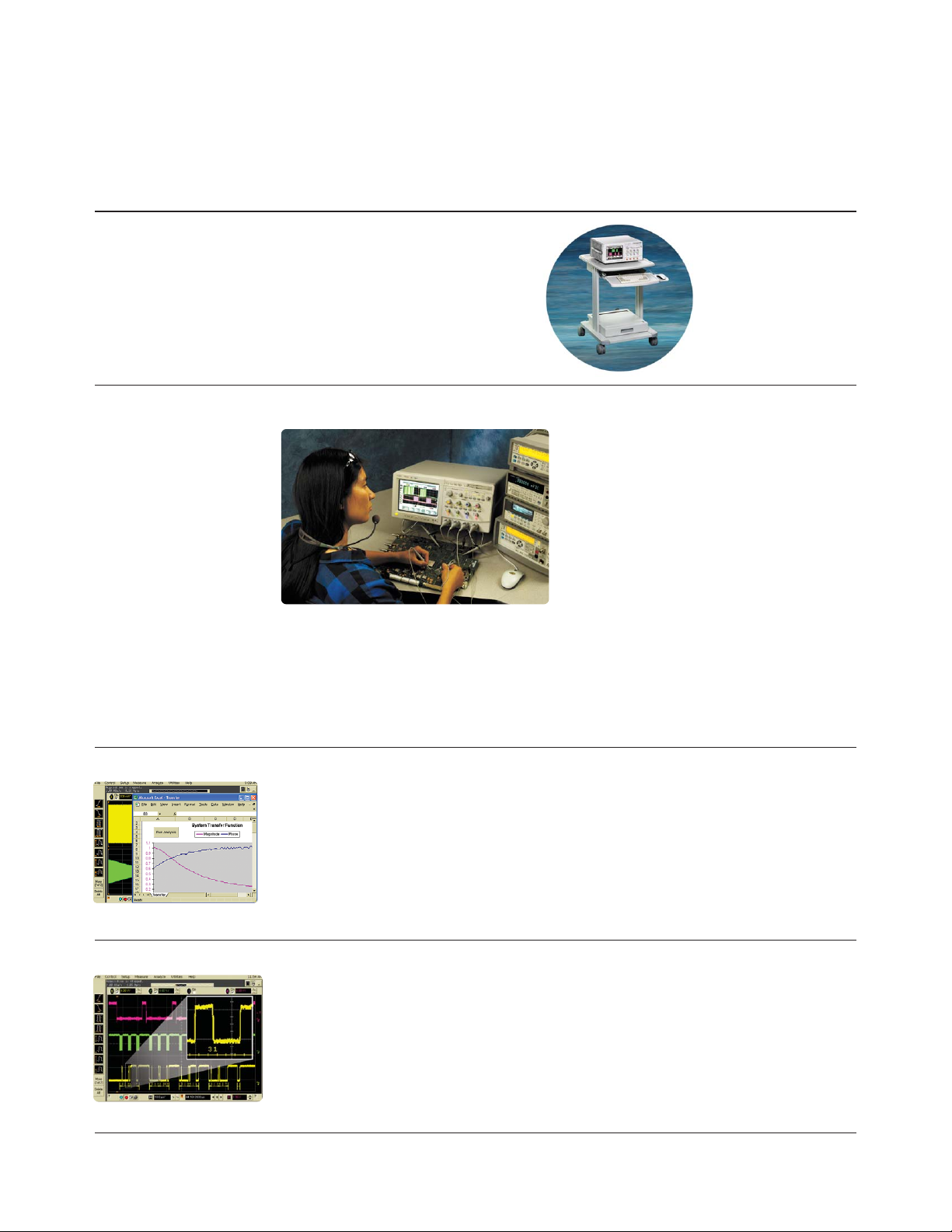
1184A Testmobile.
Agilent’s 1184A testmobile provides
a convenient solution for your portability
and storage needs. The 1184A includes
a drawer for accessories and a keyboard
tray with a mouse extension for either
right- or left-handed operation.
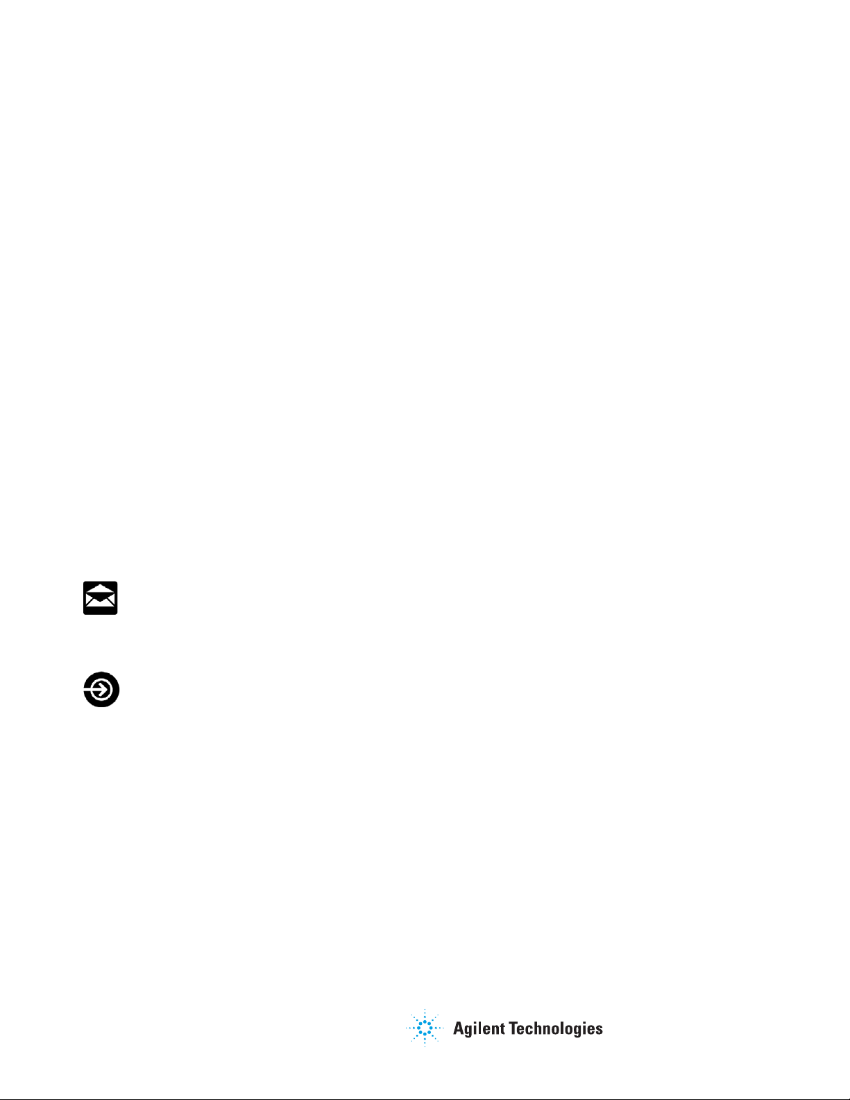
E2682A VoiceControl Option.
If you’re making measurements on target systems with densely packed Ics, your hands are
tied up holding probes, making it difficult to turn knobs and press buttons on the front panel
of your scope. Infiniium’s award-winning VoiceControl option solves this problem. Just speak
into the collar-mounted microphone to operate your Infiniium’s front-panel controls without
using your hands. Simply tell the scope what you want it to do, using natural English-language
commands, such as “set channel one to 1 volt per division.” The VoiceControl system does not
require the scope to be trained to understand a particular user.
E2699A My Infiniium Integration Package
My Infiniium allows you to extend the power of your Windows XP-based Infiniium oscilloscope
by letting you launch customized applications, such as those written for Agilent VEE Pro,
NI LabVIEW, MATLAB
®
or Microsoft Excel, directly from the oscilloscope’s front panel or
graphical user interface.
For more detailed information, please request Agilent publication number 5988-9934EN.
N5391A Low-Speed Serial Data Analysis Software.
Provides a fast and easy way to debug Inter-Integrated Circuit (I
2
C) and 2-wire or 3-wire
Serial Peripheral Interface (SPI) serial communication busses. The Low-Speed SDA software,
when used with the Agilent 54830 Series or 54850 Series Infiniium oscilloscopes, provides
the ability to capture and automatically display decoded serial data in numerical format
synchronized with the analog or digital waveform view of I
2
C or SPI serial data streams.
Page 26

26
Ordering Information (continued)
1130 Series InfiniiMax probing system
Probe amplifiers model Description
1134A 7 GHz InfiniiMax probe amp – order one or more probe heads or connectivity kits.
1132A 5 GHz InfiniiMax probe amp – order one or more probe heads or connectivity kits.
1131A 3.5 GHz InfiniiMax probe amp – order one or more probe heads or connectivity kits.
Connectivity kits model Description
E2669A InfiniiMax connectivity kit for differential/single-ended measurements. Includes a
differential browser, four solder-in differential probe heads and two socketed
differential probe heads. Includes all necessary accessories.
E2668A InfiniiMax connectivity kit for single-ended measurements. Includes one
single-ended browser, one solder-in probe head and one socketed probe head.
Includes all necessary accessories.
Individual probe heads Description
E2675A InfiniiMax differential browser probe head and accessories. Includes 20 replaceable
tips and ergonomic handle. Order E2658A for replacement accessories.
E2676A InfiniiMax single-ended browser probe head and accessories. Includes 2 ground collar
assemblies, 10 replaceable tips, a ground lead socket and ergonomic browser handle.
Order E2663A for replacement accessories.
E2677A InfiniiMax differential solder-in probe head and accessories. Includes 20 full bandwidth
and 10 medium bandwidth damping resistors. Order E2670A for replacement accessories.
E2678A InfiniiMax single-ended/differential socketed probe head and accessories. Includes 48 full
bandwidth damping resistors, 6 damped wire accessories, 4 square pin sockets and
socket heatshrink. Order E2671A for replacement accessories. Order E5381-82103 for
34 damped wire accessories only.
E2679A InfiniiMax single-ended solder-in probe head and accessories. Includes 16 full bandwidth
and 8 medium bandwidth damping resistors and 24 zero ohm ground resistors. Order E2672A
for replacement accessories.
E2695A Differential SMA probe head. Includes semi-rigid coax to change span between
SMA cables. Works with InfiniiMax 1130 series probe amplifiers.
Adapters Description
N1022A Adapts 113x/115x active probes to 86100 Infiniium DCA.
Page 27

27
www.agilent.com/find/infiniimax
Ordering Information (continued)
1130 Series InfiniiMax probing system (continued)
Other compatible probes Description
1144A 800 MHz active probe. Requires 1142A probe power supply when used with Infiniium scopes.
Requires 01144-61604 probe power extender when using two or more 1144A active probes.
1145A 2-channel, 750 MHz active probe. Requires 1142A power supply when used with
Infiniium oscilloscopes.
1156A 1.5 GHz single-ended active probe for Infiniium scopes.
1157A 2.5 GHz single-ended active probe for Infiniium scopes.
1158A 4 GHz single-ended active probe for Infiniium scopes.
54006A 7.5 GHz passive resistive divider probe – 10:1 (500 ohms) or 20:1 (1 kohms).
Page 28

28
Ordering Information (continued)
Related Literature
Publication Title Publication Type Publication Number
Infiniium 54800 Series Oscilloscopes Data Sheet 5988-3788ENUS
Option 008, 7 GHz Enhanced Data Sheet 5989-1066EN
Bandwidth Oscilloscope
E2681A EZJIT Jitter Analysis Software Data Sheet 5989-0109EN
E2690A Timing Interval & JItter Data Sheet 5988-9723EN
Analysis Software
E2683A USB 2.0 Compliance Test Sotfware Data Sheet 5989-0236EN
E2688A High-Speed Serial Data Data Sheet 5989-0108EN
Analysis Software
Using Agilent InfiniiMax Probes with Configuration Guide 5989-1869EN
Test Equipment other than Agilent
Infiniium Oscilloscopes
Infiniium 54800 Series Oscilloscope Selection Guide 5968-7141EUS
Probes, Accessories and Options
Advantages and Disadvantages of Using Application Note 5989-1145EN
DSP Filtering on Oscilloscope Waveforms 1494
Restoring Confidence in Your Application Note 5988-7951EN
High-Bandwidth Probe Measurements 1419-01
Understanding Usability Versus Application Note 5988-8005EN
Performance on High-Bandwidth 1419-02
Active Oscilloscope Probes
Performance Comparison of Differential Application Note 5988-8006EN
and Single-Ended Active Voltage Probes 1419-03
Understanding Oscilloscope Frequency Application Note 5988-8008EN
Response and Its Effect on Rise 1420
Time Accuracy
Understanding and Using Offset in Application Note 5988-9264EN
InfiniiMax Active Probes 1451
Finding Sources of Jitter Application Note 5988-9740EN
with Real-Time Jitter Analysis 1448-2
The Agilent 81134A pulse/pattern generator provides high
speed stimulus to your devices, with pulses, patterns and
PRBS data from 15 MHz to 3.35 GHz. You can also perform
stressed eye diagram measurements with jitter on PRBS,
data and clock signals.
Product Web site
For the most up-to-date and
complete application and product
information, please visit our
product Web site at:
www.agilent.com/find/infiniimax
Page 29
www.agilent.com
www.agilent.com/find/infiniimax
Agilent Technologies’ Test and Measurement Support, Services, and Assistance
Agilent Technologies aims to maximize the value you receive, while minimizing your risk and
problems. We strive to ensure that you get the test and measurement capabilities you paid
for and obtain the support you need. Our extensive support resources and services can help
you choose the right Agilent products for your applications and apply them successfully.
Every instrument and system we sell has a global warranty. Two concepts underlie Agilent's
overall support policy: "Our Promise" and "Your Advantage."
Our Promise
Our Promise means your Agilent test and measurement equipment will meet its advertised
performance and functionality. When you are choosing new equipment, we will help you
with product information, including realistic performance specifications and practical
recommendations from experienced test engineers. When you receive your new Agilent
equipment, we can help verify that it works properly and help with initial product operation.
Your Advantage
Your Advantage means that Agilent offers a wide range of additional expert test and
measurement services, which you can purchase according to your unique technical and
business needs. Solve problems efficiently and gain a competitive edge by contracting with
us for calibration, extra-cost upgrades, out-of-warranty repairs, and on-site education and
training, as well as design, system integration, project management, and other professional
engineering services. Experienced Agilent engineers and technicians worldwide can
help you maximize your productivity, optimize the return on investment of your Agilent
instruments and systems, and obtain dependable measurement accuracy for the life of
those products.
For more information on Agilent Technologies’
products, applications or services, please
contact your local Agilent office. The complete
list is available at:
www.agilent.com/find/contactus
Phone or Fax
United States:
(tel) 800 829 4444
(fax) 800 829 4433
Canada:
(tel) 877 894 4414
(fax) 800 746 4866
China:
(tel) 800 810 0189
(fax) 800 820 2816
Europe:
(tel) 31 20 547 2111
Japan:
(tel) (81) 426 56 7832
(fax) (81) 426 56 7840
Korea:
(tel) (080) 769 0800
(fax) (080) 769 0900
Latin America:
(tel) (305) 269 7500
Taiwan:
(tel) 0800 047 866
(fax) 0800 286 331
Other Asia Pacific Countries:
(tel) (65) 6375 8100
(fax) (65) 67556 0042
Email: tm_ap@agilent.com
Contacts revised: 05/05/05
Product specifications and descriptions in this
document subject to change without notice.
© Agilent Technologies, Inc. 2005
Printed in USA, May 12, 2005
5988-7976EN
www.agilent.com/find/emailupdates
Get the latest information on the products and applications you select.
Agilent T&M Software and Connectivity
Agilent's Test and Measurement software and connectivity products, solutions and
developer network allows you to take time out of connecting your instruments to your
computer with tools based on PC standards, so you can focus on your tasks, not on your
connections. Visit www.agilent.com/find/connectivity for more information.
MATLAB®is a U.S. registered trademark of Math Works, Inc.
Windows
®
is a U.S. registered trademark of Microsoft Corporation.
Intel
®
and Pentium®is a U.S. registered trademark of Intel Corporation.
EZ-Probe Positioner
®
is a registered trademark of Cascade Microtech.
www.agilent.com/find/agilentdirect
Quickly choose and use your test equipment solutions with confidence.
Agilent Email Updates
Agilent Direct
 Loading...