

Page 1

The Oscilloscopes for
Digital System
Developers
Agilent Technologies
Infiniium 54830 Series Oscilloscopes
Contents
Features and Benefits 2
Options and Accessories 12
Performance Characteristics 17
Purchasing Alternatives 24
Ordering Information 25
Page 2

2
Award-winning scopes
Infiniium has received eight
industry awards to date, including EDN’s “Innovation of the
Year” award (twice) and T&M
World’s “Best in Test.” Agilent is
committed to breaking new
ground and providing tools that
bring unique value to our customers.
Now with mixed-signal oscilloscope models, Infiniium makes
it faster and easier than ever to see what's happening in your
high-speed, mixed-signal design.
The performance you need
• 600 MHz to 1 GHz bandwidth
• 2+16-, 4+16-, 2- and 4-channel
models
• Up to 4 GSa/s
• Up to 4 Mpts memory standard; up
to 16 Mpts, optional
• Advanced probing solutions
View up to 4 analog and 16
digital channels
With the addition of the new
Agilent 54830D Series of MixedSignal Oscilloscopes (MSOs),
you can easily view the complex
relationships of your analog and
digital signals, as well as the
analog characteristics of digital
signals. If your designs include
16- to 32-bit embedded systems
with both analog and digital
components, the 54830D Series
of MSOs can help you easily
trigger on and view up to 20
time-aligned analog and digital
signals.
Instant Response, Optimum
Resolution
A deep-memory scope doesn’t
have to be difficult to use.
Infiniium scopes from Agilent
Technologies can simplify your
debugging tasks and help you
easily discover intermittent
problems in your design
Page 3

3
“Everything is where you want it to
be. Readouts, knobs — they are easy
to see, easy to use.”
Matt Berger
Senior Engineering Technician
National Semiconductor
“Other scopes are hard to use, hard to
maneuver. With Infiniium, it’s easy to
find your way around when you’re
looking for advanced features.”
Norm Reed
Radar Systems Technologist
Canadian Department of
National Defense
“We use Infiniium to save large quantities of screen shots on our LAN —
then we pull them up immediately
over the network. It saves a lot of time
and a lot of hassle.”
Stu Nuffer
Senior Systems Engineer
LSI Logic
”Complex triggering has its place, but
sometimes I just want to capture
everything and look at it.”
Chuck Hill
Consultant
Alta Engineering
Here’s what engineers are saying about their Infiniium scopes.
Simple things are simple
Analog-like front panel provides
simple controls for basic functions — easy to find and easy
to use.
Easy access to advanced features
Familiar Windows®-based graphical user interface makes it easy
to navigate and access advanced
features.
Convenient communication and
data sharing
PC architecture with a standard
LAN interface makes it easy to
share your work and communicate your results.
Automatic deep memory with
instant response
With Infiniium’s MegaZoom deep
memory, you can easily make
long single-shot acquisitions and
search through your data with
instant response.
Page 4

Powerful Mixed-Signal Triggering
No matter how complicated the
signals you’re dealing with, the
Infiniium MSO has a triggering
feature that can help you easily
untangle it. The Infiniium MSOs
provide you with the most complete triggering functionality
ever offered in an oscilloscope.
The 54830D Series Infiniium
MSOs come with powerful triggering capabilities across all 16
digital channels and all available analog channels so you can
easily isolate and analyze complex signals and interactions in
your mixed analog and digital
designs.
Seamless Integration of Analog and
Digital Channels
The Agilent 54830D Series
Mixed- Signal Oscilloscopes
uniquely combine the detailed
signal analysis of a high-performance scope with the 16-channel
timing measurements of a logic
analyzer, plus the benefits of fast,
usable, and affordable MegaZoom
deep memory.
On one display you can have
both the analog circuit characteristics displayed on the 2 or 4
scope channels and the digital
signals displayed on the 16 logic
timing channels. Digital and
analog events are aligned in
time so you can easily relate
cause and effect in difficult
mixed-signal troubleshooting
situations. The analog and
digital channels are seamlessly
integrated giving you familiar
scope-like controls of both the
analog and digital timing channels. And there is no compromise on the scope side — you
just can treat all 18 or 20
channels the same.
4
Verifying and analyzing your mixed-signal design
Here we see a data line and the clock
of a standard SDRAM isolated in a
write cycle. This was accomplished by
triggering with 4 digital channels of the
54833D MSO when the SDRAM’s CS,
CAS, and WE lines are low, while RAS
is high on the rising edge of the clock.
The increased channels, deep memory,
and advanced triggering of an MSO
can help you debug today's complex
designs more efficiently than you could
with a DSO. Trying to do this with a
traditional 2- or 4-channel DSO would
be difficult or impossible. The traditional
option for measuring a multi-channel
system would be to connect and
configure a logic analyzer with a DSO
which can be costly and time-consuming.
Fortunately, Agilent’s MSO fills this
need without the cost or frustration.
Page 5

The 54830 Series Infiniium
scopes use advanced MegaZoom
technology so you get all the benefits of fast, automatic, affordable deep memory. Due to its
unique ASIC architecture, this
powerful memory management
system called MegaZoom can
quickly display up to 16 million
points of continuous signal history without the usual bottlenecks
and frustrating delays.
5
Deep memory without annoying delays
Instant Response
While first-generation deep-memory scopes update the display
slowly, Infiniium’s MegaZoom
memory management system
instantaneously updates the display even with the deepest memory. And deep memory is on all
the time — so you always have the
maximum available sample rate
and don’t undersample or miss
fast events. Discover problems
you never found with your firstgeneration deep-memory scope.
Optimum Resolution
Get the insight you need to solve
your debugging challenges in a
fraction of the time it used to
take. Just press the Autoscale key
to automatically adjust the sample
rate to achieve the best waveform
resolution. Then, as you change
the horizontal scale to display
more time and view your entire
signal, MegaZoom adds more
memory to give you the fastest
sample rate and best resolution
possible. Now you can see events
as narrow as 250 ps without using
a special mode such as peak
detect.
Affordable Deep Memory
Every Infiniium with MegaZoom
is a deep-memory oscilloscope
with up to a standard 2 Mpts
of memory on each channel.
Memory options to 8 Mpts on
each channel are available and
cost up to 60 percent less than
the price of first-generation
deep memory oscilloscopes.
Infiniiums are affordable enough
that all of your scopes can be
deep-memory models.
By combining powerful features,
ease of use, and the right specifications, Infiniium scopes help
you find answers faster. A simple, analog-like front panel,
Windows-based interface, and
powerful connectivity capabilities make high-performance features accessible and uncomplicated-all with the performance
and features you need for
today’s demanding jobs.
Page 6

See fast events — as fast as 250 ps —
without using special modes like peak
detect. Peak points are displayed in a
darker color than the waveform indicating more data points are available. Just
zoom in to see the event in detail.
Drag and drop markers with your
mouse or use the arrow keys.
Bus mode display allows quick
readout of digital channel value in
hexa-decimal representation at
every transition.
See your signal more clearly with a
large (8.4-inch) high-resolution color
display. Infiniium's bright TFT display
with anti-glare coating lets you see the
details of your signal from all angles.
Store all your setups and results on
the ≥20 GB hard drive for future recall
or sharing via the LAN interface.
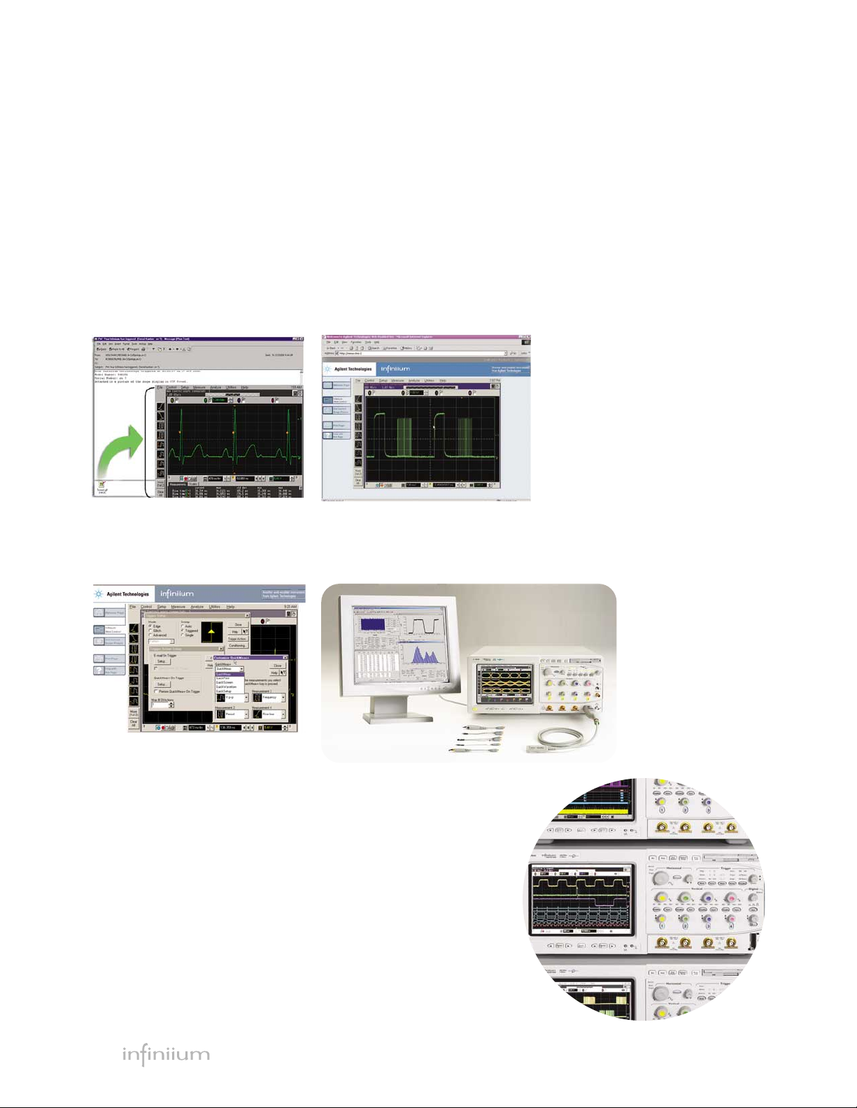
Remote access with web-enabled
connectivity, e-mail on trigger, and
GPIB over LAN.
Windows®XP Pro based open
platform makes it easier than ever
to run Windows applications inside
of Infiniium.
Save all waveforms, including digital
and analog channels, that allows you
to store multiple waveforms in ASCII
file formats to a single file with a
single mouse click.
6
Infiniium: “It’s like someone who sits down and
actually uses a scope designed this one.”
Steve Montgomery
Director of Engineering, Linx Technologies
Get fast answers to your questions
with the built-in information system.
Infiniium's task-oriented Setup Guide
provides step-by-step instructions for
several advanced measurements and
procedures.
Maximum sample rate and resolution
on every measurement. The scope
automatically adjusts memory depth
as you use it, so you get maximum
sample rate and resolution on every
measurement. You don't even have to
think about it.
Pick out anomalies easily with
intensity-graded persistence mode,
color-graded persistence, a colorful
visual representation of waveform
distribution.
QuickMeas+ gives you any four auto-
mated measurements with the push of
a button. You can also configure this
key to print/save screen shots, save
waveforms, or load a favorite setup.
With the E2699A My Infiniium
Software option, configure the
QuickMeas+ key to execute a custom
analysis executable program.
Page 7

7
Autoscale automatically sets deep
memory to the amount required for
the maximum sample rate and resolution. You never have to set deep memory manually.
120 MB LS-120 SuperDisk floppy drive
makes it easy to save your work (to
super floppies or standard 3.5-inch
disks) and update your system software.
A familiar interface makes simple
tasks simple. Infiniium's analog-like
front panel has a full set of controls
color coded to the LEDs, waveforms,
and measurements.
Easy access to advanced features
like math and FFTs is provided by the
Windows-based graphical user interface. This GUI also gives you unique
capabilities like drag-and-drop measurements and zooming, and offers a graphical equivalent to all front panel controls.
AutoProbe interface completely
configures your scope for use with
a wide range of passive, active and
differential probes.
10/100 Mbps LAN interface lets you
easily print waveforms on networked
printers, save your results on your
office PC, and share information
with others.
Roll mode display allows for
continuous scrolling capture of
slow analog signals
Hands-free operation with the
Infiniium VoiceControl option. Just
speak into the collar-mounted microphone to operate front-panel controls.
Label waveforms and add notes to
your screen captures — Infiniium's
keyboard makes it easy.
Built-in CD-ROM drive on the rear
panel allows you to update the system
software conveniently.
Zoom and search with instant
response. Zoom into your signal using
the horizontal scale knob and search
through your waveform with the position knob. Find your area of interest
quickly and easily.
4 analog and 16 digital channel
MSOs allow you to see up to 20 time-
aligned signals on your scope screen.
Also available in 2+16- , 2- and 4channel models.
Page 8

8
Infiniium: Helping you get the job done faster
Drag-and-Drop Measurements
It’s simple: drag an icon from the
measurement bar and drop it on
the cycle you want to measure.
You can make up to four measurements on your waveforms,
on up to four different cycles.
All the measurements appear at
the bottom of the display with
statistics and are color coded to
the channel you are measuring.
Scope measurements have never
been this powerful or this easy.
Dialog Boxes for Easy Setup
With Infiniium, you don’t need
to navigate through annoying
softkey menus. Dialog boxes
display all the choices you need
for measurement setups, all in
one place. Help is available for
each field, guiding you through
each step.
Bus Mode Display
Bus mode display on MSOs
allows quick and easy read-out
of hexa-decimal representation
of logic signals. Bus state mode
display allows the bus readout
to be updated only upon the
edge of the clock source you
select. Available only with
54830D Series MSOs.
Simple Zooming
Zooming with Infiniium’s graphical user interface is simple and
convenient. Just use the mouse
to draw a box around the area of
interest and click inside. Zoom
uses the full display so you get
meaningful vertical as well as
horizontal resolution gains. Use
multiple zoom boxes to see deep
inside your signal. Zooming
couldn’t be simpler or faster.
Windows XP Pro Open System
Want to run Windows applications inside your Infiniium
scope? Yes you can. All Infiniium
54830 Series scopes are based on
Windows XP Pro open platform
that allows you to run Windows
applications inside the Infiniium
to add advanced analysis and
functionaliy to the scope.
Page 9

9
AutoMask and Mask Test
Mask testing is simplified with
AutoMask. Acquire a waveform,
define tolerance limits, and create
a test envelope. Mask testing provides a pass/fail comparison of an
incoming signal to the test envelope. Easily test your design’s conformance to industry standards
with the Communication Mask
Test Kit option.
Advanced Triggering
Advanced triggers are essential
when investigating known problems. Infiniium offers a full range
of advanced triggers to help
you isolate and capture the condition you need to characterize.
Advanced trigger setups are simplified by using intuitive dialog
boxes with descriptive graphics.
Color-Graded Persistence
with Histograms
By providing seven levels
of color grades for a visual
representation of waveform
distribution, color-graded
persistence makes it easy to
pick out signal anomalies and
see how often they occur.
Histograms quantify both noise
and jitter in your target system.
Infiniium: Simplifying tasks with easy access to advanced features
Intensity-Graded Persistence
The intensity-graded persistence
mode displays waveforms in the
seven levels of intensity grades,
enabling you to capture elusive
signal anomalies in complex
waveforms using user defined
decay time.
High/Low Pass Filter
Applies a real-time digital filter
to the source waveform that you
choose. This filtering feature
enhances your ability to examine
important signal components by
filtering out unwanted frequency
components.
QuickMeasure and Statistics
Instantly make four common
measurements on your signal,
with easy-to-read statistics, by
pressing the QuickMeas+ button
on the front of your Infiniium.
The measurements displayed can
be easily customized.
Page 10
10
Infiniium: Simplifying tasks with easy access to advanced features
E-Mail on Trigger
Infiniium can automatically send
an e-mail with a bit map of the
display when the scope triggers.
You can have your Infiniium
send an e-mail to you or a
message to your cell phone then
control your scope from any
Java-enabled web browser.
Web-Enabled Control
For distributed teams, simply set
up Infiniium on your LAN, and up
to three users can access it from
any Java™-enabled Web browser.
No special software is required.
You can easily grab screen shots
for a report, or troubleshoot
designs at a remote location.
GPIB Commands over LAN
Send GPIB commands over
the LAN or access data from
Infiniium scopes at remote
locations worldwide — or from
your home or office.
Dual Monitor Support
Dual Monitor mode
allows you to run
third-party applications
on a large, external
monitor with up to SXGA
resolution (1280 x 1024
pixels) while using the
scope’s built-in monitor
for waveform display.
Infiniium IVI-COM Driver
For higher-level of instrument
control, utilize the Infiniium
IVI-COM instrument driver in
your application. This IVI-COM
driver takes full advantage of
industry accepted standards
and is compatible in application
development environments
such as Visual Studio® as well
as in test and measurement
development environments
such as Agilent VEE Pro
and National Instruments®
LabView®. The Infiniium
IVI-COM Instrument driver
allows for easier use, higher
performance, and instrument
interchangeability in your
oscillscope control program.
Download the Infiniium IVI-COM
driver for free from Agilent
Developer’s Network at
www.agilent.com/find/adn.
Page 11

11
Infiniium: High-performance scopes at competitive prices
54800 Series Infiniium Oscilloscopes
Maximum Standard Optional
Mode Bandwidth Channels Sample Rate Acquisition Memory Max. Acquisition Memory
54830D 600 MHz 2+16 4 GSa/s 2 Mpts/ch (4 Mpts max.) 8 Mpts/ch (16 Mpts max.)
54831D 600 MHz 4+16 4 GSa/s 2 Mpts/ch (4 Mpts max.) 8 Mpts/ch (16 Mpts max.)
54832D 1 GHz 4+16 4 GSa/s 2 Mpts/ch (4 Mpts max.) 8 Mpts/ch (16 Mpts max.)
54833D NEW 1 GHz 2+16 4 GSa/s 2 Mpts/ch (4 Mpts max.) 8 Mpts/ch (16 Mpts max.)
54830B 600 MHz 2 4 GSa/s 2 Mpts/ch (4 Mpts max.) 8 Mpts/ch (16 Mpts max.)
54831B 600 MHz 4 4 GSa/s 2 Mpts/ch (4 Mpts max.) 8 Mpts/ch (16 Mpts max.)
54832B 1 GHz 4 4 GSa/s 2 Mpts/ch (4 Mpts max.) 8 Mpts/ch (16 Mpts max.)
54833A NEW 1 GHz 2 4 GSa/s 500 kpts/ch (1 Mpts max.) 8 Mpts/ch (16 Mpts max.)
Common to All Infiniium 54830
Series Oscilloscopes
• 600 MHz and 1 GHz bandwidths
• Maximum 4 GSa/s sample rate
• 2 Mpts/ch MegaZoom memory
standard (4 Mpts max)
(except for 54833A)
• Optional 4 or 8 Mpts memory per
channel (8 or 16 Mpts max)
• Windows XP Pro based open system
• Simple analog-like front panel
• Advanced features are accessible
with Windows GUI
• File and printer sharing with LAN
• Web-enabled, remote control
from any web browser
• E-mail on trigger
• Intensity-graded persistence
• High/low pass filter functions
• Dual monitor support
• Advanced triggering
• Color-graded persistence
and histograms
• Drag-and-drop measurements
and zoom boxes
• USB (2), mouse, keyboard, GPIB,
VGA, LAN, Centronics ports
• QuickMeasure+
• Statistics
• Built-in information system
• ≥20 GB HDD, 120 MB superdisk
floppy
• Waveform labels
• Math functions including FFTs
• Advanced, quiet multi-fan
cooling system
• CD-ROM drive
• Optical USB mouse,
condensed keyboard
• ATX PC motherboard
• Pentium®III 1 GHz processor
• 512 MB CPU memory
• Eye diagram measurements
• AutoMask
• My Infiniium integration
package option
• EZJIT jitter analysis software option
• Time interval and jitter
analysis option
• Ethernet masks option
• Communications mask testing option
• USB 2.0 pre-compliance testing
option (for 4-ch or 4+16-ch
models only)
• VoiceControl option,
hands-free control
• InfiniiMax 1130 Series probe support
• Standard 1-year warranty
Page 12

12
Options and Accessories
Microsoft Windows XP Pro
open operating system with
expanded 512MB CPU memory.
The new system software offers
users reliable system performance and the ability to run
Windows applications inside
the scope, making it a one-box
acquisition/analysis solution.
Infiniium Performance Upgrade
Kit (N5383A)
The N5383A Infiniium
Performance Upgrade Kit
upgrades your existing Infiniium
54830 Series oscilloscopes to
the A.03.10 or higher version of
the system software based on
application directly from the
oscilloscope’s front panel or
graphical user interface. Any
program that can be run under
Windows XP can be launched
from Infiniium scope, including
applications such as Agilent VEE,
Microsoft Excel, or MATLAB.
My Infiniium Integration Package*
(Option 006 or E2699A)
The E2699A My Infiniium
Integration Package option
allows you to extend the power
of your Infiniium oscilloscope
by letting you launch your
hold time, measurement histograms, measurement trending
and jitter spectrum. Our jitter
option provides a setup wizard
to guide you through the setup
of the jitter measurement, how
each jitter measurement works,
and tells you when to use it.
EZJIT Jitter Analysis Software*
(Option 015 or E2681A)
The E2681A Jitter Analysis
option provides the most
commonly needed jitter measurements, including cycle-cycle
jitter, N-cycle jitter, period jitter,
time interval error, setup and
signals. The option provides
four mask templates for
10BaseT testing, two mask
templates for 100BaseT testing,
and six mask templates for
1000BaseT testing as defined by
IEEE 802.3 specification.
Ethernet Masks* (E2698A)
The E2698A Ethernet Masks
option provides mask templates
for 1000BaseTX, 100BaseT and
10BaseT. These masks provide
pass/fail testing for Ethernet
with the Infiniium 54830 Series
oscilloscopes provides the most
repeatable and fully-featured jitter measurements for serial data
streams, PLLs and high-speed
clock designs.
Time Interval and Jitter Analysis*
(E269xA and N538xA)
The E269xA and N538xA Time
Interval and Jitter Analysis software licensed from Amherst
System Associates combined
* This option works with all 54830 Series Infiniium oscilloscopes and requires Infiniium system software version A.03.10 or higher (Windows XP Pro). Existing 54830 Series users can order the
N5383A Infiniium performance upgrade kit to move from A.02.XX (Windows 98) to A.03.50 (Windows XP pro) or higher revision of the system software.
Page 13

13
Options and Accessories continued
USB 2.0 Test Option
(E2683A or N2855A)
The Agilent Technologies
Infiniium USB 2.0 test option
makes USB signal-integrity
compliance testing as simple as
capturing the signals with your
oscilloscope. Infiniium has significantly reduced the work
associated with USB compliance
testing by eliminating the need
to transfer scope signals
to a PC. The Infiniium USB 2.0
test option features run-time
MATLAB® embedded in the
scope for use with the USB
signal integrity scripts, providing
a one-box solution. The USB-IF
compliance program recognizes
Infiniium as a recommended
scope for use in compliance
testing. In addition, all MATLAB
scripts used with the USB test
option come from the USB-IF
organization.
This option works with all
Infiniium 4-ch or 4+16-ch
54800 Series oscilloscopes and
includes both the USB test
option software and Signal
Quality Inrush Droop/Drop
(SQiDD) test fixture. Additional
SQiDD test fixtures can be purchased separalety by ordering
the E2646A.
High-Speed Serial Data Analysis
Software† (Option 003 or N5384A)
The Agilent Technologies HighSpeed Serial Data Analysis
(SDA) software provides an
effective way to validate signal
integrity for designs employing
high-speed serial interfaces with
embedded clocks. The HighSpeed SDA software, when used
with the Agilent 54830 Series
Infiniium oscilloscopes, allows
you to:
•recover embedded clocks with
first-order PLL, second-order
PLL, or constant frequency
algorithms
•choose an external reference
clock input
•display the recovered clock
synchronized with the analog
waveform view of the serial
data stream
•build real-time eye diagrams
•unfold real-time eye diagrams
to easily locate failures versus
time
•perform custom mask testing
•make TIE jitter measurements
relative to the recovered clock
or external reference clock
Low-Speed Serial Data Analysis
Software† (Option 021 or N5391A)
The Agilent Technologies LowSpeed Serial Data Analysis
(SDA) software provides a fast
and easy way to debug InterIntegrated Circuit (I2C) and 2wire or 3-wire Serial Peripheral
Interface (SPI) serial communication busses. The Low-Speed
SDA software, when used with
the Agilent 54830 Series or
54850 Series Infiniium oscilloscopes, provides the ability to
capture and automatically display decoded serial data in
numerical format synchronized
with the analog or digital waveform view of I2C or SPI serial
data streams.
†This option works with all 54830 Series Infiniium oscilloscopes and requires version A.03.50 (Windows XP Pro) system software or higher. Existing 54830 Series users can order the
N5383A Infiniium Performance Upgrade Kit to move from A.02.XX (Windows 98) to A.03.50 (Windows XP Pro) or higher revision of system software
Page 14

14
Options and Accessories continued
Communication Mask Test Kit
(E2625A)
Take the frustration out of communications testing and prove
your designs conform to industry standards with the
Communication Mask Test Kit
option. Infiniium’s familiar
Windows interface makes it easy
for you to access the masks you
need and configure your tests.
In addition, the Communication
Mask Test Kit comes with a set of
electrical communication adapters
to ensure convenient, reliable,
and accurate connections to
your device under test. Includes
more than 20 industry-standard
ANSI T1.102, ITU-T G.703, and
IEEE 802.3 communication signal mask templates. This option
works with all Infiniium 54800
Series oscilloscopes.
Logic Analyzer/Oscilloscope
Time-Correlation Fixture (E5850A)
Now you can more effectively
verify and track down problems
between the analog and digital
portions of a design. Easily make
time-correlated measurements
between an Agilent 16700 Series
logic analysis system or Agilent
1680/90 Series benchtop logic
analyzer and an Infiniium 54800
Series oscilloscope. With the
E5850A Time-Correlation Fixture,
you can trigger the Infiniium
from the logic analyzer (or vice
versa), automatically deskew the
waveforms, and simultaneously
view the Infiniium analog waveforms and the logic analyzer’s
timing waveforms on your
Agilent logic analyzer. This
option works with all Infiniium
54800 Series oscilloscopes.
Testmobile (1184A)
Agilent’s 1184A testmobile provides a convenient solution for
your portability and storage needs.
The 1184A includes a drawer for
accessories and a keyboard tray
with a mouse extension for either
right- or left-hand operation.
Agilent Wedge Probe Adapters
offer a safe, easy method for
connection to surface-mount
ICs. The Wedge makes two
contact points with each leg
of the IC. There’s no need to
worry about accidentally shorting IC pins together on a delicate
component — or worse yet on an
irreplaceable prototype.
Wedge adapters are available
for probing 3, 8, or 16 signals
with 0.5 mm and 0.65 mm TQFP
and PQFP packages. The Wedge
easily attaches to Infiniium
probes, connecting directly to
the 1155-58A active probes and
the 1160A family of miniature
passive probes.
Wedge Probe Adapters (Option 007)
Page 15

15
Options and Accessories continued
Vector Signal Analysis software for
Infiniium (89601A)
Analyze wideband modulation
with the Infiniium scopes and
89601A Vector Signal Analyzer
Software. The Infiniium’s
high-quality, high-speed ADCs
handle down-converted LMDS,
MMDS and satellite signals up to
1.5 GHz BW. The VSA software
provides flexible demodulation
and analysis capabilities for
troubleshooting modulated
signals. Included are 24 digital
demodulators with automatic
carrier and clock recovery,
various filter types and a large
selection of analysis displays
(constellation, eye diagram,
spectrum, EVM spectrum).
Measure EVM, MER, frequency
offset, I/Q offset, gain and
phase imbalance. You can even
demodulate down to the bit
level. The 89601A software runs
inside the Infiniium, or on a PC
connected to the Infiniium via
LAN or GPIB. This option works
with all Infiniium 54800 Series
oscilloscopes.
Instrument Viewer
®
The MicroOptical® SV-3
Instrument Viewer projects an
image of your Infiniium VGA
display in front of you, like
having a monitor anywhere you
want it. For additional information and ordering instructions,
contact the MicroOptical Corp or
see http://www.microoptical.net.
VoiceControl Option
(E2682A or N2850A)
If you’re making measurements
on target systems with densely
packed ICs, your hands are tied
up holding probes, making it
difficult to turn knobs and press
buttons on the front panel of
your scope. Infiniium’s awardwinning VoiceControl option
solves this problem. Just
speak into the collar-mounted
microphone to operate your
Infiniium’s front-panel controls
without using your hands.
Simply tell the scope what you
want it to do, using natural
English-language commands,
such as “set channel one to
1.25 volts per division.” The
VoiceControl system does not
require the scope to be trained
to understand a particular user.
This option works with all
Infiniium 54800 Series
oscilloscopes.
Order N2850A for an existing
Infiniium 54830 Series
(version A.02.xx) purchase.
Order E2682A for a new
Infiniium 54830 Series (version
A.03.10 or later) purchase.
TMControl™ Scope
TMControl Scope is a full-featured
Windows application that enables
data analysis on-scope and also
by connectivity through your PC.
It’s the ideal solution for transferring data and documenting
test results with your scope
without programming and without requiring other PC application software. With TMControl
Scope, you can capture and study
your data using markers, pan
and zoom, and customize your
view of your data with annotation and edit controls. For more
information and to purchase,
visit http://www.tmcontrol.com.
Page 16

16
Options and Accessories continued
Active Probes (Options 011, 012, 019)
Probing high-frequency signals
becomes more challenging as the
variety of test points and the frequencies of the signals continue
to grow. Probes need to be lightweight, small, affordable, and
offer the accessories and probe
tips you require to get your job
done easily.
For high-speed differential
signal measurements, the 1130A
InfiniiMax differential probe
is a perfect compliment to the
Infiniium 54830 Series oscilloscopes. Its 1.5 GHz probe bandwidth, extremely low input
capacitance, high common mode
rejection and the patented resistor probe tip technology provide
ultra-low loading of the DUT and
superior signal fidelity.
The 1156A active probe is a
small, low-mass, active probe
with bandwidth up to 1.5 GHz.
The probe offers a flat frequency
response across the entire probe
bandwidth, giving you accurate
insight into your high-speed
measurement. Agilent offers
a variety of probe tips to help
you probe any test point, and
the revolutionary EZ-Probe
Positioner® option provides stable, accurate X, Y, Z positioning
of your probe.
The 1155A probe is a low-mass,
versatile, and affordable 2-channel, 750-MHz active probe. Used
with an optional Wedge Probe
Adapter, this combination is an
excellent solution for probing
TQFP and PQFP packages. When
used with the standard grabber
tips, the 1155A can be used to
probe any test point. When used
with the 600 MHz Infiniium
oscilloscopes, this pairing delivers 2 channels with a system
bandwidth of 500 MHz.
For more information on probing
solutions, accessories, and
options, please visit our web site
at www.agilent.com/find/infiniium;
and see the Infiniium 54800
Series Oscilloscope Probes,
Accessories, and Options
Selection Guide, (Agilent literature No. 5968-7141 EN/EUS) and
many other useful documents
and webpages.
Single-Ended/
Model Probe Bandwidth System Bandwidth Channels Differential Option No.
1155A 750 MHz 500 MHz with 54830B/D or 31B/D 2 single 011
1156A 1.5 GHz 1 GHz with 54832B/D or 33A/D 1 single 012
1130A NEW 1.5 GHz 1 GHz with 54832B/D or 33A/D 1 differential* 019**
* Supports both differential and single-ended measurements.
** Adds one 1130A 1.5 GHz InfiniiMax probe amplifier and one E2675A differential browser.
Page 17

17
Vertical : Analog Channels 54830B, 54831B, 54832B, 54833A, 54830D, 54831D, 54832D and 54833D
Input Channels 54830B/54833A: 2 analog
54830D/54833D: 2 analog + 16 digital
54831B/54832B: 4 analog
54831D/54832D: 4 analog + 16 digital
Analog Bandwidth @50 Ω (-3 dB)*
1
54830B/D, 54831B/D: 600 MHz
54832B/D, 54833A/D: 1 GHz
Calculated Rise Time
2
@50 Ω 54830D/B, 54831B/D: 583 ps
54832B/D, 54833A/D: 350 ps
Input Impedance* 1 MΩ ± 1% (13 pF typical), 50 Ω ± 1.5%
Sensitivity
3
1 mV/div to 5 V/div (1 MΩ)
1 mV/div to 1 V/div (50 Ω)
Input Coupling 1 MΩ: AC, DC; 50 Ω:DC
Hardware Bandwidth Limit 20 MHz
Vertical Resolution
4
8 bits, ≥12 bits with averaging
Channel-to-Channel Isolation DC to 50 MHz: 50 dB
(any two channels with equal V/div settings) >50 MHz to 500 MHz: 40 dB
>500 MHz to 1 GHz: 30 dB
DC Gain Accuracy*
3, 5
± 1.25% of full scale at full resolution channel scale
Maximum Input Voltage*
1 MΩ 150 V RMS or DC, CAT I
± 250 V (DC + AC) in AC coupling
50 Ω 5 Vrms, CAT I
Offset Range Vertical Sensitivity Available Offset
1 MΩ 1 mV to <10 mV/div ± 2 V
10 mV to <20 mV/div ± 5 V
20 mV to <100 mV/div ± 10 V
100 mV to <1 V/div ± 20 V
1 V to 5 V/div ± 100 V
50 Ω 1 mV to <5 mV/div ± 2 V
5 mV to <200 mV/div ± 5 V
200 mV to 1 V/div ± 20 V
Offset Accuracy*
3
± (1.25% of channel offset+2% of full scale+1 mV)
Dynamic Range ± 8 div from center screen (1 MΩ)
± 12 div from center screen (50 Ω)
DC Voltage Measurement Accuracy*
3, 5
Dual Cursor ± [(DC gain accuracy)+(resolution)]
Single Cursor ± [(DC gain accuracy)+(offset accuracy)+(resolution/2)]
Example for single cursor accuracy for 70 mV signal, 10 mV/div, 0 offset: Accuracy =
± [1.25% (80 mV) + (1.25% (0) + 2% (80 mV) + 1 mV ) + (0.4%/2) (80 mV)] = ±3.8 mV
Performance Characteristics
Page 18

18
Vertical: Digital Channels (54830D/31D/32D/33D only)
Number of Channels 16 Digital – labeled D15 – D0
Threshold Groupings Pod 1: D7 – D0
Pod 2: D15 – D8
Threshold Selections TTL, 5.0V CMOS, 3.3V CMOS, 2.5V CMOS, ECL, PECL, User Defined
User-Defined Threshold Range ±8.00 V in 10 mV increments
Maximum Input Voltage ±40 V peak CAT I
Threshold Accuracy* ±(100 mV + 3% of threshold setting)
Input Dynamic Range ±10 V about threshold
Minimum Input Voltage Swing 500 mV peak-to-peak
Input Impedance 100 kΩ ± 2% (~ 8 pF) at probe tip
Channel-to-Channel Skew 2 ns typical, 3 ns maximum
Glitch Detect ≥ 2.5 ns
Resolution 1 bit
Horizontal 54830B, 54831B, 54832B, 54833A, 54830D, 54831D, 54832D and 54833D
Main Time Base Range 54830B/D, 54831B/D 54832B/D, 54833A/D
500 ps/div to 20 s/div 200 ps/div to 20 s/div
Horizontal Position Range 0 to ± 200 s
Delayed Sweep Range 1 ps/div to current main time base setting
Resolution 4 ps
Timebase Accuracy 15 ppm (±0.0015%)
Delta-Time Measurement Accuracy 54830B/D, 54831B/D 54832B/D, 54833A/D
≥ 256 Averages, RMS 500 fs rms 400 fs rms
≥ 256 Averages, Peak ±[(2.2 ps) + (15x10
-
6
x |reading|)] peak ±[(2.0 ps) + (15x10
-
6
x |reading|)] peak
Average Disabled, RMS 10 ps rms 7 ps rms
Average Disabled, Peak ±[(35 ps) + (15x10
-
6
x |reading|)] peak ±[(25 ps) + (15x10
-
6
x |reading|)] peak
Channel-to-Channel Deskew Range –100 µs to 100 µs
Modes Main, Delayed, Roll
Reference Positions Left, Center, Right
Jitter Measurement Floor 54830B/D, 54831B/D 54832B/D, 54833A/D
Time Interval Error 7 ps rms 5 ps rms
Period Jitter 10 ps rms 7 ps rms
N-Cycle, Cycle-Cycle Jitter 15 ps rms 11 ps rms
Performance Characteristics continued
Page 19

19
Acquisition: Analog Channels 54830B, 54831B, 54832B, 54833A, 54830D, 54831D, 54832D and 54833D
Real Time Sample Rate (Max)
2 Channels Interleaved 4 GSa/s
Each Channel 2 GSa/s
Equivalent Time Sample Rate (Max) 250 GSa/s
Memory Depth Interleaved/each channel
Standard 4 M / 2 M (1 M / 500 K for 54833A)
Option 040 8 M / 4 M
Option 080 16 M / 8 M
Real Time Averaging Mode 2 M / 1 M
Equivalent Time Sampling 32 K
Sampling Modes
Real Time Successive single-shot acquisitions
Equivalent Time Random repetitive sampling (higher time resolution at faster sweep speeds)
Peak Detect Captures and displays narrow pulses or glitches at all real time sample rates
Hi Resolution Real-time boxcar averaging reduces random noise and increases resolution
Averaging Selectable from 2 to 4096
Filters
Sin[x])/x Interpolation Filter On/Off selectable FIR digital filter. Digital signal processing adds points between acquired
data points to enhance measurement accuracy and waveform display quality. BW= Sample Rate/4
Acquisition: Digital Channels (54830D/31D/32D/33D only)
Maximum Real Time Sample Rate 1 GSa/s
Memory Depth per channel 4 M
Minimum Width Glitch Detection 2.5 ns
Performance Characteristics continued
Page 20

20
Trigger 54830B, 54831B, 54832B, 54833A, 54830D, 54831D, 54832D and 54833D
Sensitivity
Internal
8
DC to 600 MHz: 0.6 div
600 MHz to 1 GHz: 1.5 div (50 Ω)
External DC to 100 MHz: 0.05 x (signal range)
100 MHz to 600 MHz: 0.10 x (signal range) (54830B/D, 54833A/D)
600 MHz to 1 GHz: 0.18 x (signal range) (54833A/D)
Auxiliary DC to 600 MHz: 300 mVp-p (54831B/31D/32B/32D/33A/33D)
Level Range
Internal ± 8 div from center screen (1 MΩ)
± 8 div from center screen (50 Ω)
External ± 1 V, ± 5 V, ± 25 V (1 MΩ)
± 1 V, ± 5 V, ± 8 V (50 Ω) (54830B/D, 54833A/D)
Auxiliary ± 5 V (54831B/32B/31D/32D/33A/33D)
Sweep Modes Auto, triggered, single
Trigger Coupling DC, AC, low frequency reject (50 kHz high pass filter), high frequency reject
(50 kHz low pass filter)
Trigger Conditioning Noise reject adds hysteresis to trigger circuitry decreasing sensitivity to noise
Trigger Holdoff Range 80 ns to 320 ms (54830A/B Series)
50 ns to 10 s (54830D Series)
Trigger Jitter 8 ps ± 0.05 ppm x |delay setting| rms
Trigger Actions Specify an action to occur, and the frequency of the action, when a trigger condition
occurs. Actions include: e-mail on trigger and QuickMeas+
Trigger Modes
Edge Triggers on a specified slope and voltage level on any channel, auxiliary trigger (4 channel models),
external trigger (2 channel models) or line input.
Glitch Triggers on glitches narrower than the other pulses in your waveform by specifying a width less
than your narrowest pulse and a polarity. Minimum glitch width is 500 ps (analog channels) or
2.5 ns (digital channels on 54830D/31D/32D/33D). Glitch range settings: <1.5 ns to <160 ms
(54830A/B Series), <1.5 ns to <10 s (analog channels on 54830D/31D/32D/33D),
<5 ns to <10 s (digital channels on 54830D/31D/32D/33D)
Line Triggers on the line voltage powering the oscilloscope.
Pattern Triggers when a specified logical combination of the channels is entered, exited, is present or
absent for a specified period of time or is within a specified time range. Each channel can have a
value of High (H), Low (L) or Don’t care (X).
State Pattern trigger clocked by the rising or falling edge of one channel. Logic type: AND or NAND.
Delay by Time The trigger is qualified by an edge. After a specified time delay between 30 ns to 160 ms (5 ns to
10 s for 54830D/31D/32D/33D) a rising or falling edge on any one selected input will generate
the trigger.
Delay by Events The trigger is qualified by an edge. After a specified delay between 1 to 16,000,000 rising or falling
edges on any one selected input will generate the trigger.
TV Trigger on one of the three standard television waveforms: 525 lines/60 Hz (NTSC)
625 lines/50 Hz (PAL), or define a custom waveform
Violation Triggers
Pulse Width See Trigger Mode Glitch for performance characteristics.
Setup/Hold Triggers on setup, hold or setup and hold violations in your circuit. Requires a clock and data signal
on any two input channels as trigger sources. High and low thresholds and setup and/or hold
time must then be specified.
Transition Trigger on pulse rising or falling edges that do not cross two voltage levels in > or < the amount of
time specified.
Performance Characteristics continued
Page 21

21
Trigger: Digital Channels (54830D/31D/32D/33D only)
Threshold Range (user defined) ±8.0 V in 10 mV increments
Threshold Accuracy* ±(100 mV + 3% of threshold setting)
Predefined Thresholds TTL=1.4 V, 5.0 V CMOS=2.5 V, 3.3 V CMOS=1.65 V, 2.5 V CMOS=1.25 V,
ECL=–1.3 V, PECL=3.7 V
Measurements and Math 54830B, 54831B, 54832B, 54833A, 54830D, 54831D, 54832D and 54833D
Waveform Measurements
Voltage (analog channels only) Peak-to-Peak, Minimum, Maximum, Average, RMS, Amplitude, Base, Top, Overshoot, Preshoot,
Upper, Middle, Lower, Area
Time (all channels) Period, Frequency, Positive Width, Negative Width, Duty Cycle, Delta Time
(analog channels only) Rise Time, Fall Time, Tmin, Tmax, Channel-to-Channel Phase
Frequency Domain FFT Frequency, FFT Magnitude, FFT Delta Frequency, FFT Delta Magnitude
Eye Pattern Eye Height, Eye Width, Jitter, Crossing %, Q-Factor, Duty Cycle Distortion
Measurement Modes
Automatic Measurements Measure menu access to all measurements, 4 measurements can be displayed simultaneously
QuickMeas+ Front panel button activates five pre-selected or five user defined automatic measurements
Drag and Drop Measurement Toolbar Measurement toolbar with common measurement icons that can be dragged and dropped onto
the displayed waveforms
Statistics Displays the mean, standard deviation, minimum and maximum measurement values for the
displayed automatic measurements
Histograms (analog channels only) Vertical (for timing and jitter measurements) or horizontal (noise and amplitude change) modes,
regions are defined using waveform markers. Measurements included: mean, standard deviation,
peak-to-peak value, median, total hits, peak (area of most hits), and mean ± 1,2, and 3 sigma
Eye Diagram Measurements Eye diagram display mode allows triggering on both negative-going and positive-going
edges of a signal. Eye diagram measurements include eye height, eye width, jitter, crossing
percentage, Q factor, and duty cycle distortion
Mask Testing Allows pass/fail testing to user-defined or Agilent-supplied waveform templates. AutoMask allows
user to create a mask template from a captured waveform and define tolerance range in
time/voltage or percentage. Test modes include test forever, test to specified time or event limit,
and stop on failure. Communications Mask Test Kit Option provides a set of ITU-T G.703, ANSI
T1.102, and IEEE 802.3 industry standard masks for compliance testing
Marker Modes Manual Markers, Track Waveform Data, Track Measurements
Waveform Math 4 functions f1-f4. Select from Add, Average, Differentiate, Divide, FFT Magnitude, FFT Phase,
High Pass Filter, Integrate, Invert, Low Pass Filter, Magnify, Min, Max, Multiply, Subtract, Versus
FFT
Frequency Range
6
DC to 2 GHz (2 channels interleaved), DC to 1 GHz (each channel)
Frequency Resolution Resolution = Sample Rate / Memory Depth
Best resolution at maximum sample rate 4 GSa/s / 16 M = 250 Hz
Frequency Accuracy (1/2 frequency resolution)+(5x10
-5
)(signal frequency)
Signal-to-Noise Ratio
9
80 dB at 1 Mpts memory depth
Window Modes Hanning, Flattop, Rectangular
Performance Characteristics continued
Page 22

22
Display, Computer System
and Peripherals, I/O Ports 54830B, 54831B, 54832B, 54833A, 54830D, 54831D, 54832D and 54833D
Display 8.4 inch diagonal color TFT-LCD
Resolution 640 pixels horizontally x 480 pixels vertically
Annotation Up to 12 labels, with up to 100 characters each can be inserted into the waveform area
Waveform Styles Connect Dots, Dots, Persistence (minimum, variable, infinite), Color Graded Infinite
Persistence
Simutaneous Grides 1, 2, or 4
Display Update Rate7
Standard Waveforms/second > 3,100
Standard Vp-p Measurements/second > 190
Maximum Waveforms/second > 8,800
Maximum Vp-p Measurements/second > 200
Deep Memory Waveforms/second > 50
Deep Memory Vp-p > 10
Measurements/second
Computer System and Peripherals
CPU Intel Pentium
®
III 1 GHz microprocessor
CPU Memory 512 MB
Drives ≥20 GB internal hard drive, CD-ROM drive on rear panel, LS-120 Superdisk floppy drive
reads/writes from/to both standard 3.5 inch 1.44 MB and 120 MB disks
Peripherals Logitech optical USB mouse and condensed keyboard supplied. All Infiniium models
support any Windows compatible input device with a serial, PS/2 or USB interface
File Types
Waveforms Internal Y values; X and Y values in ASCII or Microsoft Excel formats
Images BMP, PCX, TIFF, GIF or JPEG
I/O Ports
LAN RJ-45 connector, supports 10Base-T and 100Base-T. Enables Web-enabled remote
control, e-mail on trigger or demand, data/file transfers and network printing
GPIB IEEE 488.2, fully programmable
RS-232 (serial) COM1, printer and pointing device support
Parallel Centronics printer port
PS/2 2 ports. Supports PS/2 pointing and input devices
USB 2 ports. Allows connection of USB peripherals and pointing devices while the
oscilloscope is on
Video Output 15 pin VGA, full color
Auxiliary Output DC (±2.4 V); square wave (715 Hz[±15%], [±5%]); trigger output (255 mV p-p into 50 Ω)
TTL Output TTL compatible signal
Performance Characteristics continued
Page 23

23
General Characteristics 54830B, 54831B, 54832B, 54833A, 54830D, 54831D, 54832D and 54833D
Temperature
Operating 0°C to + 50°C
Non-operating –40°C to + 70°C
Humidity
Operating Up to 95% relative humidity (non-condensing) at +40°C
Non-operating Up to 90% relative humidity at +65°C
Altitude
Operating Up to 4,600 meters (15,000 feet)
Non-operating Up to 15,300 meters (50,000 feet)
Vibration
Operating Random vibration 5-500 Hz, 10 minutes per axis, 0.3 g(rms)
Non-operating Random vibration 5-500 Hz, 10 minutes per axis, 2.41 g(rms); resonant search 5-500 Hz, swept
sine, 1 octave/minute sweep rate, (0.75g), 5 minute resonant dwell at 4 resonances per axis
Power 100-240 VAC, ± 10%, Cat II, 47 to 440 Hz; Max power dissipated: 390 W
Weight Net: 13.4 kg (29.5 lbs.)
Shipping: 16.4 kg (36.1 lbs.)
Dimensions (excluding handle) Height: 216 mm (8.5 in); Width: 437 mm (17.19 in); Depth: 440 mm (17.34 in)
Safety Meets IEC1010-1 +A2, CSA certified to C22.2 No.1010.1, Self certified to UL 3111
* Denotes Warranted Specifications, all others are typical. Specifications are valid after a 30-minute warm-up period and ±10°C from firmware calibration temperature.
1 Typical system bandwidth for 54830 Series in 1 MΩ input with standard 1165A passive probe attached is 600 MHz.
2 Rise time figures for 54830 Series are calculated from t r = 0.35/bandwidth.
3 54830B/31B/32B/33A/30D/31D/32D/33D: Magnification is used below 5 mV/div range. Below 5 mV/div, full scale is defined as 40 mV. Full scale is defined as the major
attenuator setting above an intermediate setting. (Major settings 50 Ω: 10 mV, 20 mV, 50 mV, 100 mV, 200 mV, 500 mV, 1 V, 1 MΩ: all of the above plus 2 V).
4 Vertical resolution for 8 bits = 0.4% of full scale, for 12 bits = 0.024% of full scale.
5 The dc gain accuracy decreases 0.08% of full scale per degree C from the firmware calibration temperature.
6 FFT amplitude readings are affected by input amplifier roll-off 54830/31B/D (–3 dB at 600 MHz, with amplitude decreasing as frequency increases above 600 MHz),
54832B/32D/33A/33D: (–3 dB at 1 GHz, with amplitude decreasing as frequency increases above 1 GHz).
7 Standard measurement condition: Real time mode, 512 pts memory, minimum persistence display mode, triggered sweep mode, no interpolation, markers off, math off,
connect dots off, 1 channel acquisition, 50 ns/div, only analog channels on (for 54830D models). Maximum condition is the same as standard condition except time/div is
set to 1 ns/div. Deep memory condition is the same as standard condition except time/div is set to 200 µs/div and memory depth is set to 8 Mpts per channel.
8 For 54830B Series specification valid for vertical ranges > 5 mV / div.
9 Noise floor varies as memory depth increases with averaging on.
Performance Characteristics continued
Page 24

24
Rent Today
If your need is short term, turn
to our Preferred Rental Partners
(PRPs) to rent equipment for up
to 12 months. Our PRPs offer
you the latest Agilent equipment
and configuration options,
along with fast delivery and
exceptional service. For details,
contact your closest PRP.
Electro Rent (US)
www.electrorent.com/agilent
888-893-5996
TRS (US)
www.trsonesource.com/agilent
877-610-5010
Microlease (Europe)
www.microlease.com/agilent
+44 (0) 20 84 200 200
Trade-Up
Do you already own an Infiniium
oscilloscope? Capitalize on your
previous investment by trading
it in for a substantial credit on a
new model with advanced deep
memory or more bandwidth.
Our trade-up program helps you
stretch your equipment budget
and better manage your assets
while upgrading to the latest
solutions.
We also offer special promotions
that make it easier than ever
for you to acquire the latest
technologies. Contact your local
Agilent representative to find the
Infiniium that’s right for you and
the best option for acquiring it.
http://buyalternatives.tm.agilent.com
The Infiniium scope you buy
today must also meet your performance requirements for
tomorrow. Ensure that your
equipment can handle your
future needs with the right scope
and purchasing plan. Before you
select the Infiniium scope that’s
right for you, consider these
flexible purchasing options, so
you can get the best tools for
the job, regardless of your
company’s financial constraints.
Lease and Finance
If you’d like to improve your
balance sheet by expensing
equipment costs, or your budget
won’t cover the purchase price up
front, consider our leasing and
financing plans. We offer many
flexible options: select the term
you need, choose from various
paths for end of term, and even
revise your plan to include
eligible upgrades and add-ons.
Contact your local Agilent
Financial Services Center
for details.
Flexible purchasing alternatives help you acquire
the instruments you need
Page 25

25
Agilent Model Channels Bandwidth Sample Rate Memory Depth
54830D 2+16 600 MHz
54831D 4+16 600 MHz
54832D 4+16 1 GHz
54833D NEW 2+16 1 GHz
54830B 2 600 MHz
54831B 4 600 MHz
54832B 4 1 GHz
54833A NEW 2 1 GHz
The above models include: Optical USB Mouse, Condensed Keyboard, User's Quick Start Guide in English language (other languages also available), Documentation CD
(Service Guide, Programmer’s Guide), Recovery CD, Information System in English language**, accessory pouch (54810-68701), front panel cover, power cord, and threeyear warranty.
Ordering Information and Configuration
4 GSa/s (interleaved = CH/2)
2 GSa/s on each channel
4 M (interleaved = CH/2)
2 M on each channel
Standard Probes Included
Agilent Model Passive Probes Logic Cable Kit
54830D 1165A 10:1 10 MΩ probes (Qty 2) 54826-68701 MSO logic cable kit (Qty 1)
54831D 1165A 10:1 10 MΩ probes (Qty 4) 54826-68701 MSO logic cable kit (Qty 1)
54832D* None 54826-68701 MSO logic cable kit (Qty 1)
54833D* None 54826-68701 MSO logic cable kit (Qty 1)
54830B 1165A 10:1 10 MΩ probes (Qty 2) None
54831B 1165A 10:1 10 MΩ probes (Qty 4) None
54832B* None None
54833A* None None
* Passive probes not included, please order option 001, 002, 004, or active probe option 012, 019 (for 54832B/D, 54833A/D).
1 M (interleaved = CH/2)
500 K on each channel
For information about higher
bandwidth scope and probing
solutions (up to 6 GHz of
system bandwidth), please
visit our web site at
www.agilent.com/find/infiniimax
New 54852A, 2 GHz bandwidth,
10 GSa/s sample rate per channel
affordably priced.
More information available at
www.agilent.com/find/infiniimax
Page 26

26
Options Description
Acquisition Memory Options (for analog channels only)
040 8 Mpts on half the acquisition channels (interleaved) (54830B/D, 54833A/D)
or 4 Mpts on each acquisition channel (54831B/D, 54832B/D)
080 16 Mpts on half the acquisition channels (interleaved) (54830B/D, 54833A/D)
or 8 Mpts on each acquisition channel (54831B/D, 54832B/D)
N2845A* After-purchase memory upgrade, 2 Mpts/ch to 4 Mpts/ch
N2846A* After-purchase memory upgrade, 2 Mpts/ch to 8 Mpts/ch
N2847A* After-purchase memory upgrade, 4 Mpts/ch to 8 Mpts/ch
* Users can install upgrades without opening the instrument case or requiring on-site service.
Probe Options
001 Add two 1165A, 10:1 passive probes for the 54830 Series
002 Add one 1162A 1:1 passive probe
004 Add four 1165A, 10:1 passive probes for the 54830 Series
005 Add one 54826-68701 logic probe kit
(This probe kit comes standard with the 54830D/31D/32D/33D)
007 Add one Wedge adapter kit (1 each 3/8/16 signals, 0.5 mm)
008 Add one 1153A 200 MHz differential probe
011 Add one 1155A 2 Channel, 750 MHz active probe
012 Add one 1156A 1.5 GHz active probe
016 (E2654A) EZ-Probe‚ Positioner: includes base, joystick, and articulating arm
019 Add one 1130A 1.5 GHz InfiniiMax probe amplifier and one
E2675A differential browser
E5396A Half-Size (17 channel) Soft touch connecterless Logic Probe for MSO models
Instrument Options
N5383A Infiniium Performance Upgrade Kit (required to upgrade system software
from A.02.xx to A.03.50 or higher)
006 (E2699A) My Infiniium Integration Package Option
003 (N5384A) High-Speed Serial Data Analysis Software Option
021 (N5391A) Low-Speed Serial Data Analysis Software Option
015 (E2681A) EZJIT Jitter Analysis Software Option
E2690A ADV-1 Advanced Time Interval and Jitter Analysis
(one scope license, US and Canada)
E2691A ADV-4 Advanced Time Interval and Jitter Analysis
(four scope licenses, US and Canada)
E2692A BAS-1 Basic Time Interval and Jitter Analysis (one scope license, US and Canada)
E2693A ADV-SA Subscription for one-year advanced product updates (US and Canada)
E2694A BAS-SA Subscription for one-year basic product updates (US and Canada)
E2698A Ethernet Masks Option
USB 2.0 Test Option
E2645A for 54800A Series
N2855A for 54830B/D Series with software version A.02.xx
E2683A for 54830B/D Series, 54833A and 54850A Series with software version A.03.10 or higher
E2646A Additional USB 2.0 SQiDD Test Fixture
E2625A Communication Mask Test Kit Option
Ordering Information and Configuration: Agilent Infiniium Options
Page 27

27
Ordering Information and Configuration: Agilent Infiniium Options continued
Related Literature
Publication Title Publication Type Publication Number
Agilent Technologies Digital and Mixed Signal Oscilloscopes Selection Guide 5988-8460EN/ENUS
Infiniium 54850 Series Oscilloscopes and InfiniiMax 1130 Series Probes Data Sheet 5988-7976EN/ENUS
Infiniium 54800 Series Oscilloscope Probes, Accessories and Options Data Sheet 5968-7141EN/ENUS
E2681A EZJIT Jitter Analysis Software for Infiniium 54830 and Data Sheet 5989-0109EN
54850 Series Oscilloscopes
E2690A Time Interval and Jitter Analysis Data Sheet 5988-9723EN
E2699A My Infiniium Integration Package Data Sheet 5988-9934EN
E2688A, N5384A High-Speed Serial Data Analysis and Clock Recovery Software Data Sheet 5989-0108EN
Infiniium USB Test Option Data Sheet 5989-0236EN
E2625A Communication Mask Test Kit and E2698A Ethernet Masks Data Sheet 5989-0372EN
Agilent Mixed Signal Oscilloscopes: 6-minute Video Demonstration Video CD 5988-9288EN
Options Description
Instrument Options (continued)
VoiceControl Option (English only)
E2635A for 54800A Series
N2850A for 54830B/D Series with software version A.02.xx
E2682A for 54830B/D Series and 54850A Series with software version A.03.10 or higher
1CM (E2609B) Add one rackmount kit
1184A Testmobile with keyboard and mouse tray, drawer for accessories
E5850A Time-correlation fixture, link Infiniium scope to logic analyzer
Manual Options
OB3 Printed service manual
OBF Printed programmer’s manual
AB2 Printed user’s quick start guide in simplified Chinese
ABJ Printed user’s quick start guide in Japanese
Service Option
A6J ANSI Z540-compliant calibration
Connectivity Option
TMControl Scope Data capture/analysis/archive application –
demo/application download at www.tmcontrol.com
Page 28

28
Agilent Technologies’ Test and Measurement Support, Services, and Assistance
Agilent Technologies aims to maximize the
value you receive, while minimizing your
risk and problems. We strive to ensure
that you get the test and measurement
capabilities you paid for and obtain the
support you need. Our extensive support
resources and services can help you
choose the right Agilent products for your
applications and apply them successfully.
Every instrument and system we sell has a
global warranty. Support is available for at
least five years beyond the production life
of the product. Two concepts underlie
Agilent’s overall support policy: “Our
Promise” and “Your Advantage.”
Our Promise
Our Promise means your Agilent test and
measurement equipment will meet its
advertised performance and functionality.
When you are choosing new equipment,
we will help you with product information,
including realistic performance specifications and practical recommendations from
experienced test engineers. When you use
Agilent equipment, we can verify that it
works properly, help with product operation, and provide basic measurement assistance for the use of specified capabilities,
at no extra cost upon request. Many selfhelp tools are available.
www.agilent.com
1 800 452 4844
Your Advantage
Your Advantage means that Agilent offers a
wide range of additional expert test and
measurement services, which you can purchase according to your unique technical
and business needs. Solve problems efficiently and gain a competitive edge by contracting with us for calibration, extra-cost
upgrades, out-of-warranty repairs, and onsite education and training, as well as
design, system integration, project management, and other professional engineering
services. Experienced Agilent engineers
and technicians worldwide can help you
maximize your productivity, optimize the
return on investment of your Agilent instruments and systems, and obtain dependable
measurement accuracy for the life of those
products.
By internet, phone, or fax, get assistance with
all your test & measurement needs
Online assistance:
www.agilent.com/find/assist
Phone or Fax
United States:
(tel) 800 829 4444
Canada:
(tel) 877 894 4414
(fax) 905 282 6495
China:
(tel) 800 810 0189
(fax) 800 820 2816
Europe:
(tel) (31 20) 547 2323
(fax) (31 20) 547 2390
Japan:
(tel) (81) 426 56 7832
(fax) (81) 426 56 7840
Korea:
(tel) (82 2) 2004 5004
(fax) (82 2) 2004 5115
Latin America:
(tel) (305) 269 7500
(fax) (305) 269 7599
Taiwan:
(tel) 0800 047 866
(fax) 0800 286 331
Other Asia Pacific Countries:
(tel) (65) 6375 8100
(fax) (65) 6836 0252
Email: tm_asia@agilent.com
Product specifications and descriptions in this
document subject to change without notice.
© Agilent Technologies, Inc. 2004
Printed in USA May 21, 2004
5988-3788EN
Windows is a U.S. registered trademark of Microsoft Corp.
Java is a U.S. trademark of Sun Microsystems, Inc.
M
ATLAB is a U.S. registered trademark of The Math Works, Inc.
Pentium is a U.S registered trademark of Intel Corporation
Intel is a U.S. registered trademark of Intel Corporation
EZ-Probe Positioner is a U.S. registered trademark of Cascade Microtech, Inc.
Instrument Viewer is a U.S. registered trademark of MicroOptical Corporation
Visual Studio is a U.S. registered trademark of Microsoft Corp.
LabView is a U.S. registered trademark of National Instruments
TMControl is a trademark of L-3 Analytics Corporation
www.agilent.com/find/emailupdates
Get the latest information on the
products and applications you select.
www.agilent.com/find/agilentdirect
Quickly choose and use your test
equipment solutions with confidence.
Agilent Direct
 Loading...