

Page 1

Programmer’s Quick Reference Guide
Publication Number 54810-97065
February 2001
For Safety information, Warranties, and Regulatory information,
see the pages at the end of this Guide.
Copyright Agilent Technologies 1997-2001
All Rights Reserved.
Infiniium Oscilloscopes
Page 2

In This Book
Chapter 1 shows you how to use the syntax diagrams in Chapter 2.
Chapter 2 contains the syntax diagrams for each command subsystem, and
includes tables describing the command parameter values. The syntax
diagrams include these command subsystems:
Common
Root Level
System
Acquire
Calibration
Channel
Disk
Display
External Channel
Function
Hardcopy
Histogram
Marker
Measure
Mask Test
Self-Test
Time Base
Trigger
Waveform
Waveform Memory
ii
Page 3

Contents
1 How To Remotely Program Infiniium Oscilloscopes
Using Program Headers 1-3
How To Generate Commands 1-4
Specifying Syntax of Program Messages 1-6
Specifying Syntax of Program Data 1-7
Interpreting Syntax Diagrams 1-8
Understanding A Sample Syntax Diagram 1-10
Using the Command Tree 1-13
2 Command Syntax Diagrams
Common Commands 2-4
Root Commands 2-6
SYSTem Commands 2-8
ACQuire Commands 2-10
CALibration Commands 2-13
CHANnel Commands 2-14
DISK Commands 2-18
DISPlay Commands 2-20
EXTernal Channel Commands 2-27
FUNCtion Commands 2-30
HARDcopy Commands 2-34
HISTogram Commands 2-35
MARKer Commands 2-37
MEASure Commands 2-40
Mask TESt Commands 2-50
SELFtest Commands 2-56
TIMebase Commands 2-57
TRIGger Commands 2-59
WAVeform Commands 2-79
Waveform MEMory (WMEMory) Commands 2-81
Contents-1
Page 4

Contents-2
Page 5

1
How To Remotely Program Infiniium
Oscilloscopes
Page 6

Programming Syntax
Com p ut er s co mm u nic a t e with th e os ci ll o sc o p e by send i n g and rec e i v i n g
program messages over a remote interface. To program the oscilloscope
remotely, you must understand the command format and structure
expected by the oscilloscope. The IEEE 488.2 syntax rules govern how
individual elements such as headers, separators, program data, and
terminators are grouped together to form complete instructions.
This chapter describes how to:
• Use program headers
• Generate commands
• Specify syntax of program messages
• Specify syntax of program data
• Interpret syntax diagrams
• Understand a sample syntax diagram
• Use the command tree
1- 2
Page 7

How To Remotely Program Infiniium Oscilloscopes
Using Program Headers
Using Program Headers
Program headers are key words that identify commands. There are two types
of program headers:
• Common Command
• Oscilloscope Control
Headers for Common Commands
Common command headers are IEEE 488.2-defined commands and queries.
Common command headers are preceded by an asterisk. Two examples of
common commands are:
*SAV <register>
*SAV <register>;*TRG
Headers for Oscilloscope Control Commands
Headers for oscilloscope control commands are typically related to oscilloscope
measurement and control. These commands are preceded by a colon (:). The
purpose of colons in oscilloscope-control headers is described in “Tree Traversal
Rules” later in this chapter.
1-3
Page 8

How To Remotely Program Infiniium Oscilloscopes
How To Generate Commands
How To Generate Commands
You can spe cify keyw ords and headers for oscillo scope control using either the
long form or the short form of a command. Sending a header that is not the
short form or the complete long form for the command causes the Infiniium
Oscilloscope to generate an error.
IEEE 488.2 limits the length of a header to 12 characters, including any numeric
suffix. The long form header is either a single word or an abbreviation of a
phrase. The short form header is an abbreviation of the long form header.
The syntax diagrams in this manual show both the long form and the short form
fo r each co m m and. Th e short fo rm of a co m m and is shown in upperc a s e le t ters.
How the Long-Form Command is Generated
The long-form command is generated from either a single word or from multiple
words. When a single word is used, that word becomes the command. For
example, WAVEFORM.
If multiple words are used, generally the first letter of each word and the entire
last word make up the command. For example, WMEMORY for WAVEFORM
MEMORY.
How the Short-Form Command is Generated
The short form command is usually the first four characters of the long form
command header. The exception to this is when the long form consists of more
than four characters and the fourth character is a vowel. In these cases, the
vowel is dropped and the short form becomes the first three characters of the
long form.
For example, the short form of MODE is MODE; however, the short form of
INTERPOLATE is INT because the fourth character is a vowel.
In the syntax diagrams in this manual, a special notation is used to differentiate
the short-form keyword from the long form of the same keyword. The short
form of the keyword is shown in uppercase letters, and the rest of the command
is shown in lowercase letters. For example, “BandWidth Limit” is shown as
“BWLimit”.
Including A Numeric Suffix
Oscilloscope commands allow a numeric suffix to differentiate between multiple
instances of the same command, such as with multiple channels, functions, and
waveform memories. For example, CHANnel1:BWLimit ON. The numeric suffix
is applied to both the long form and short form. For example, CHAN1 is the
short form of CHANnel1.
1- 4
Page 9

How To Remotely Program Infiniium Oscilloscopes
How To Generate Commands
Using Queries
Many of the oscilloscope commands have an additional query form. As defined
in IEEE 488.2, a query is a command header with a question mark symbol
appended: for example, :TRIGger:MODE?
When the query form of a command is received, the current setting associated
with the command is placed in the oscilloscope’s output buffer. Queries do not
cause any settings within the oscilloscope to change.
When numeric parameters are queried, the result will be returned in
fundamental units unless specified otherwise. When several different units may
be considered fundamental, the units of the returned result will be documented
in the description for the command.
1-5
Page 10

Figure 1-1
OUTPUT
CHANNEL1BWLIMT ON”
How To Remotely Program Infiniium Oscilloscopes
Specifying Syntax of Program Messages
Specifying Syntax of Program Messages
When computers communicate with the oscilloscope over a remote interface,
program messages are placed on the bus using an input or output command and
passing the device address, instruction, and terminator. Passing the device
address ensures that the instruction is sent to the correct interface and
oscilloscope.
The instructions for programming the oscilloscope normally appear as a string
of ASCII characters in the output statement of a host language available on your
computer. Responses from the oscilloscope are read with the input statements
of the ho s t lan g u a ge. F i g u r e 1- 1 sh ow s th e syn t a x of a t y p i c al HP Bas i c p r o g r a m
statement.
PROGRAM MESSAGE UNIT
707;”:
HP BASIC OUTPUT COMMAND
INFINIIUM DEVICE ADDRESS
INSTRUCTION HEADER
SEPARATOR
PROGRAM DATA
Typical Program Statement Syntax
A pr o gram me ssage is termina ted by a <N L> (new li ne). The re cogn i t ion of th e
program message terminator, or <PMT>, by the oscilloscope’s parser serves as
a signal to begin execution of commands. The <PMT> also affects oscilloscope
command tree traversal.
Each program message serves as a container for one command. Program
m e s s a g e s ar e se pa r a t e d by a s em i c o l on . A co l o n pr e ce d i ng th e co m m an d hea d e r
returns the parser to the top of the parser tree.
1- 6
Page 11

How To Remotely Program Infiniium Oscilloscopes
Specifying Syntax of Program Data
Specifying Syntax of Program Data
Program data is used to convey parameter information related to the command
header. At least one space must separate the command header or query header
from the program data. For example:
<program command><separator> <data><terminator>
When a program command or query has multiple program data, a comma
separates sequential program data. For example:
<program command><separator><data>,<data><terminator>
Example This example shows the two main types of program data used in commands:
character and numeric program data.
:MEASURE:TVOLT 1.0V,2
The two program data are 1.0V and 2.
1-7
Page 12

How To Remotely Program Infiniium Oscilloscopes
Interpreting Syntax Diagrams
Interpreting Syntax Diagrams
The flow through syntax diagrams is shown by lines and arrows. These link
together various objects used to form a command.
Objects exist in the syntax diagram as either ovals or boxes.
• Ovals indicate literal characters.
• Boxes represent command parameters defined at the end of each syntax
diagram or a blank space that separates the command from a parameter.
Flow through the syntax diagram is generally from left to right. You enter the
diagram on the left, and the syntax is satisfied when you exit the diagram on
the right.
When an element or group of elements in the diagram is repeatable, a reverse,
right-to-left path is shown around and above the element(s), and is marked with
a left-facing arrow. When an element or group of elements in the diagram are
optional, a line is shown above the element(s). A branch in the path indicates
a choice of elements.
IEEE 488.2 defines the blocks used to build messages that are sent to the
oscilloscope, including program messages and data described earlier. You can
therefore divide an entire string of commands into individual components.
In summary:
• A semicolon separates one command from another.
• Multiple data parameters are separated by a commas.
• The first data parameter is separated from the header with one or more
spaces.
• :TIMEBASE:RANGE is an example of a compound header (two or more
commands separated by colons with no spaces).
• A colon preceding the command header returns the parser to the top of the
parser tree. See also Tree Traversal Rules later in this chapter.
Uppercase and Lowercase Equivalence
Uppercase and lowercase letters are considered to be the same by the parser.
However, the syntax diagrams in this manual do not show both alternatives.
Because the uppercase and lowercase letters are equivalent, the command
AUTOSCALE is the same as the command autoscale.
1- 8
Page 13

How To Remotely Program Infiniium Oscilloscopes
Interpreting Syntax Diagrams
Space Characters
Space characters (<space>) are required in some places, and are usually
optional when used to increase the readability of a program. Space characters
are shown in the syntax diagrams in this manual. A space character is defined
as the ASCII character 32 in decimal.
1-9
Page 14

Figure 1-2
How To Remotely Program Infiniium Oscilloscopes
Understanding A Sample Syntax Diagram
Understanding A Sample Syntax Diagram
In the following syntax diagram and procedure for the measure commands, the
procedure shows you how to use the syntax diagram to form the command string
to send to the oscilloscope. For each of the following numbered steps, a number
is shown on the syntax diagram. Each number represents the part of the
diagram with which you are working.
2 3 4 5 6 7 81
9
Example Syntax Diagram
10
1 The first part of the program header is the entry point of the syntax
11
diagram. The long form of the command begins as follows:
:MEASure
The short form of the command is:
:MEAS
2 The colon is appended to the end of the command header and separates
the first command from the second command in the command header.
The long form of the command is:
:MEASure:
The short form of the command is:
:MEAS:
3 The second command is appended to the command header.
:MEASure:TEDGe
The short form of the command is:
:MEAS:TEDG
4 The space is appended to the program header and separates the
program data from the program header.
1- 10
Page 15

How To Remotely Program Infiniium Oscilloscopes
Understanding A Sample Syntax Diagram
5
The first program data entry is a set of three possible entries from which
you should select one. For this example, we will select MIDDle. This
is appended to the end of the program header. The long form is:
:MEASure:TEDGe MIDDle
The short form of the command is:
:MEAS:TEDG MIDD
6 The comma separates the first program data from the second program
data. This is appended to the end of the command string. The long form
is:
:MEASure:TEDGe MIDDle,
The short form of the command is:
:MEAS:TEDG MIDD,
7 The next program data is a set of two possible choices: a plus sign or a
minus sign. The line shown above these choices indicates that this
program data is optional and therefore not required. We will choose
not to add this program data to our command string for this example.
8 The second program data will be an integer which is shown as the
parameter occurrence in the syntax diagram. For this example, we
will append the number 7 to the end of the command string. The long
form is:
:MEASure:TEDGe MIDDle,7
The short form of the command is:
:MEAS:TEDG MIDD,7
9 The next program data set has a line above it which means that it is
optional and not required. For this example, we will include this
program data in the command string. Therefore, we will append a
comma to the command string. The long form is:
:MEASure:TEDGe MIDDle,7,
The short form of the command is:
:MEAS:TEDG MIDD,7,
10 The next program data is a set of three possible choices: CHANnel,
FUNCtion, and WMEMory. We will choose CHANnel. The long form is:
:MEASure:TEDGe MIDDle,7,CHANnel
The short form of the command is:
:MEAS:TEDG MIDD,7,CHAN
1- 11
Page 16

How To Remotely Program Infiniium Oscilloscopes
Understanding A Sample Syntax Diagram
11
The next program data is an integer which is shown as the parameter
channel_number in the syntax diagram. For this example, we will
append the number 2 to the end of the command string. The long form
is:
:MEASure:TEDGe MIDDle,7,CHANnel2
The short form of the command is:
:MEAS:TEDG MIDD,7,CHAN2
This is the final form of the command string which can be sent to the
oscilloscope. If the oscilloscope has an GPIB address of 7, the following HP
Basic program would send the command string to the oscilloscope. The long
form is:
OUTPUT 707;”:MEASure:TEDGe MIDDle,7,CHANnel2”
The short form of the command is:
OUTPUT 707;”:MEAS:TEDG MIDD,7,CHAN2”
1- 12
Page 17

How To Remotely Program Infiniium Oscilloscopes
Using the Command Tree
Using the Command Tree
The command tree in Figure 1-3 shows all of the command s in this oscillos cope
and the relationship of the commands to each other. The IEEE 488.2 common
com m a n d s are no t liste d as pa r t of th e com m a n d tr ee be cau s e they do no t affec t
the position of the oscilloscope’s parser within the tree.
When a program message terminator (<NL>, linefeed - ASCII decimal 10) or a
leading colon (:) is sent to the oscilloscope, the parser is set to the “root” of the
command tree.
Types of Commands in the Command Tree
The commands in this oscilloscope consist of three types: common commands,
root level commands, and subsystem commands.
• Com m o n command s are com m ands defi n e d by IEEE 488. 2 an d contro l some
functions that are common to all IEEE 488.2 instruments. These commands
are independent of the tree and do not affect the position of the parser within
the tree. *RST is an example of a common command.
• R o o t lev e l comm a n d s co n t rol ma ny of the ba s i c fu n c tio n s of th e os cill o s cope .
These commands reside at the root of the command tree. They can always
be parsed if they occur at the beginning of a program message or are
preceded by a colon. Unlike common commands, root level commands place
the parser back at the root of the command tree. AUTOSCALE is an example
of a root level command.
• Subsystem commands are grouped together under a common node of the
comman d tree, such as th e TIMEBASE comm ands. You may select on ly one
subsystem at a given time. When the oscilloscope is initially turned on, the
command parser is set to the root of the command tree and no subsystem is
selected.
1- 13
Page 18

How To Remotely Program Infiniium Oscilloscopes
Using the Command Tree
Tree Traversal Rules
Command headers are created by traversing down the command tree. A legal
command header from the command tree is :TIMEBASE:RANGE. This is
referred to as a compound header. A compound header is a header made up of
two or more commands separated by colons. The compound header contains
no spaces. The following rules apply to traversing the tree.
Tree Traversal Rules
A leading colon or a program message terminator (<NL> or EOI true on the last byte)
places the parser at the root of the command tree. A leading colon is a colon that is
the first character of a program header. Executing a subsystem command places
the parser in that subsystem until a leading colon or a program message terminator
is found.
In the command tree, use the last command in the compound header as a
reference point (for example, RANGE). Then, find the last colon above that
command (TIMEBASE:). That is the point where the parser resides. You can
send any command below this point within the current program message
without sending the commands that appear above them (for example,
REFERENCE).
1- 14
Page 19

Figure 1-3
How To Remotely Program Infiniium Oscilloscopes
Using the Command Tree
Command Tree
1- 15
Page 20

Figure 1-4
How To Remotely Program Infiniium Oscilloscopes
Using the Command Tree
Command Tree (Continued)
1- 16
Page 21

Figure 1-5
How To Remotely Program Infiniium Oscilloscopes
Using the Command Tree
Command Tree (Continued)
1- 17
Page 22

Figure 1-6
How To Remotely Program Infiniium Oscilloscopes
Using the Command Tree
Command Tree (Continued)
1- 18
Page 23

Figure 1-7
How To Remotely Program Infiniium Oscilloscopes
Using the Command Tree
Command Tree (Continued)
1- 19
Page 24

How To Remotely Program Infiniium Oscilloscopes
Using the Command Tree
Tree Traversal Examples
The OUTPUT statements in the following examples are written using
HP BASIC 5.0. The quoted string is placed on the bus, followed by a
carriage return and linefeed (CRLF).
Example 1 Consider the following command:
OUTPUT 707;":CHANNEL1:RANGE 0.5;OFFSET 0"
The colon between CHANNEL1 and RANGE is necessary because
CHANNEL1: RANGE is a compou nd comm and. The semicolon between
the RANGE command and the OFFSET command is required to separate
the two commands or operations. The OFFSET command does not need
CHANNEL1 preceding it because the CHANNEL1:RANGE command
sets the parser to the CHANNEL1 node in the tree.
Example 2 Consider the following commands:
OUTPUT 707;":TIMEBASE:REFERENCE CENTER;POSITION
0.00001"
or
OUTPUT 707;":TIMEBASE:REFERENCE CENTER"
OUTPUT 707;":TIMEBASE:POSITION 0.00001"
In the first line of example 2, the “subsystem selector” is implied for the
POSITION command in the compound command.
A second way to send these commands is shown in the second part of
this example. Because the program message terminator places the
parser back at the root of the command tree, you must reselect
TIMEBASE to re-enter the TIMEBASE node before sending the
POSITION command.
1- 20
Page 25

How To Remotely Program Infiniium Oscilloscopes
Example 3 Consider the following command:
OUTPUT 707;":TIMEBASE:REFERENCE
CENTER;:CHANNEL1:OFFSET 0"
In example 3, the leading colon before CHANNEL1 tells the parser to go
back to the root of the command tree. The parser can then recognize
the CHANNEL1:OFFSET command and enter the correct node.
Using the Command Tree
1- 21
Page 26

1- 22
Page 27

2
Command Syntax Diagrams
Page 28

Syntax Diagrams
The example syntax diagrams in this chapter are similar to the syntax
diagrams in the IEEE 488.2 specification. Commands and queries are
sent to the oscilloscope as a sequence of data bytes.
The allowable byte sequence for each functional element is defined by
the syntax diagram that is shown. This sequence can be determined by
following a path in the syntax diagram. The proper path through the
syntax diagram is any path that follows the direction of the arrows. If
there is a path around an element, that element is optional. If there is a
path from right to left around one or more elements, that element or
those elements may be repeated as many times as desired.
2- 2
Page 29

Command Syntax Diagrams
These syntax diagrams show the command subsystems for Infiniium
Oscilloscopes:
•Common
• Root Level
•SYSTem
•ACQuire
•CALibration
• CHANnel (1-2 channels for 54810A/20A 1-4 for other models)
•DISK
•DISPlay
• EXTernal (only available in 54810A and 54820A)
•FUNCtion
•HARDcopy
•HISTogram
•MARKer
•MEASure
•Mask TESt
•SELFtest
•TIMebase
• TRIGger
•WAVeform
• WMEMory
2-3
Page 30

Figure 2-1
Command Syntax Diagrams
Common Commands
Common Commands
Common Commands Syntax Diagram
2- 4
Page 31

Command Syntax Diagrams
Common Command Parameter Description
mask An integer, 0 to 255, representing a mask value for the bits to
be enabled in the Service Request Enable Register.
register An integer, 0 through 9, specifying the register used to save
the current oscilloscope setup or recall a stored setup.
Common Commands
2-5
Page 32

Figure 2-2
Command Syntax Diagrams
Root Commands
Root Commands
channel_number is 1
or 2 for 54810/20 and
1 - 4 for other models.
Root Commands Syntax Diagram
2- 6
Page 33

Figure 2-3
Command Syntax Diagrams
Root Commands
channel_number is 1 or 2
for 54810/20 and
1 - 4 for other models.
Root Commands Syntax Diagram (Continued)
Root Command Parameter Description
channel_number, function_number,
wmemory_number
mask The decimal weight of the enabled bits.
serial_number The serial number of the oscilloscope in the form USXXXXXXXX.
setup_memory_number An integer, 0 through 9.
An integer, 1 or 2, for 54810 and 54820. An integer, 1 through 4, for all
other Infiniium Oscilloscope models.
2-7
Page 34

Figure 2-4
Command Syntax Diagrams
SYSTem Commands
SYSTem Commands
System Commands Syntax Diagram
2- 8
Page 35

Figure 2-5
Command Syntax Diagrams
SYSTem Commands
System Commands Syntax Diagram (Continued)
System Command Parameter Description
binary_block_data A string, consisting of 2048 bytes of setup data.
day An integer from 1 to 31.
hour 0..23.
minute 0..59.
month An integer from 1 to 12.
second 0..59.
string An alphanumeric character array up to 89 bytes long.
year An integer.
2-9
Page 36

Figure 2-6
Command Syntax Diagrams
ACQuire Commands
ACQuire Commands
ACQuire Commands Syntax Diagram
2- 10
Page 37

Figure 2-7
Command Syntax Diagrams
ACQuire Commands
ACQuire Commands Syntax Diagram (Continued)
ACQuire Command Parameter Description
channel_number An integer, 1 or 2, for 54810 and 54820. An integer, 1 through 4, for all other
Infiniium Oscilloscope models.
count_value An integer, 2 to 4096.
percent An integer, 0 to 100.
points_value An integer (see the Points Value Ranges, Table 2-1, for valid ranges).
rate A floating-point sample rate (see the SRATe command for valid rates.
2- 11
Page 38

Command Syntax Diagrams
ACQuire Commands
Table 2-1
Points Value Ranges
54810A/15A/20A/25A 54846A/45A/35A
2-channel mode
Real Time mode 16 to 32768 16 to 65536 16 to 32768
Equivalent Time mode 16 to 32768 mode not available 16 to 32768
Peak Detect mode 16 to 16384 mode not available mode not available
54846A/45A/35A
4-channel mode
2- 12
Page 39

Figure 2-8
channel_number is 1 or 2
for 54810/20 and
1 - 4 for other models.
Command Syntax Diagrams
CALibration Commands
CALibration Commands
CALibration Commands Syntax Diagram
CALibration Command Parameter Description
channel_number An integer, 1 or 2, for 54810 and 54820. An integer, 1 through
4, for all other Infiniium Oscilloscope models.
dc_value A real number indicating the calibration output DC value,
adjustable from -2.5 V to +2.5 V.
skew_value A real number indicating the channel-to-channel skew.
2- 13
Page 40

Figure 2-9
Command Syntax Diagrams
CHANnel Commands
CHANnel Commands
channel_number is 1 or 2 for 54810/20
and 1 - 4 for other models.
CHANnel Commands Syntax Diagram
2- 14
Page 41
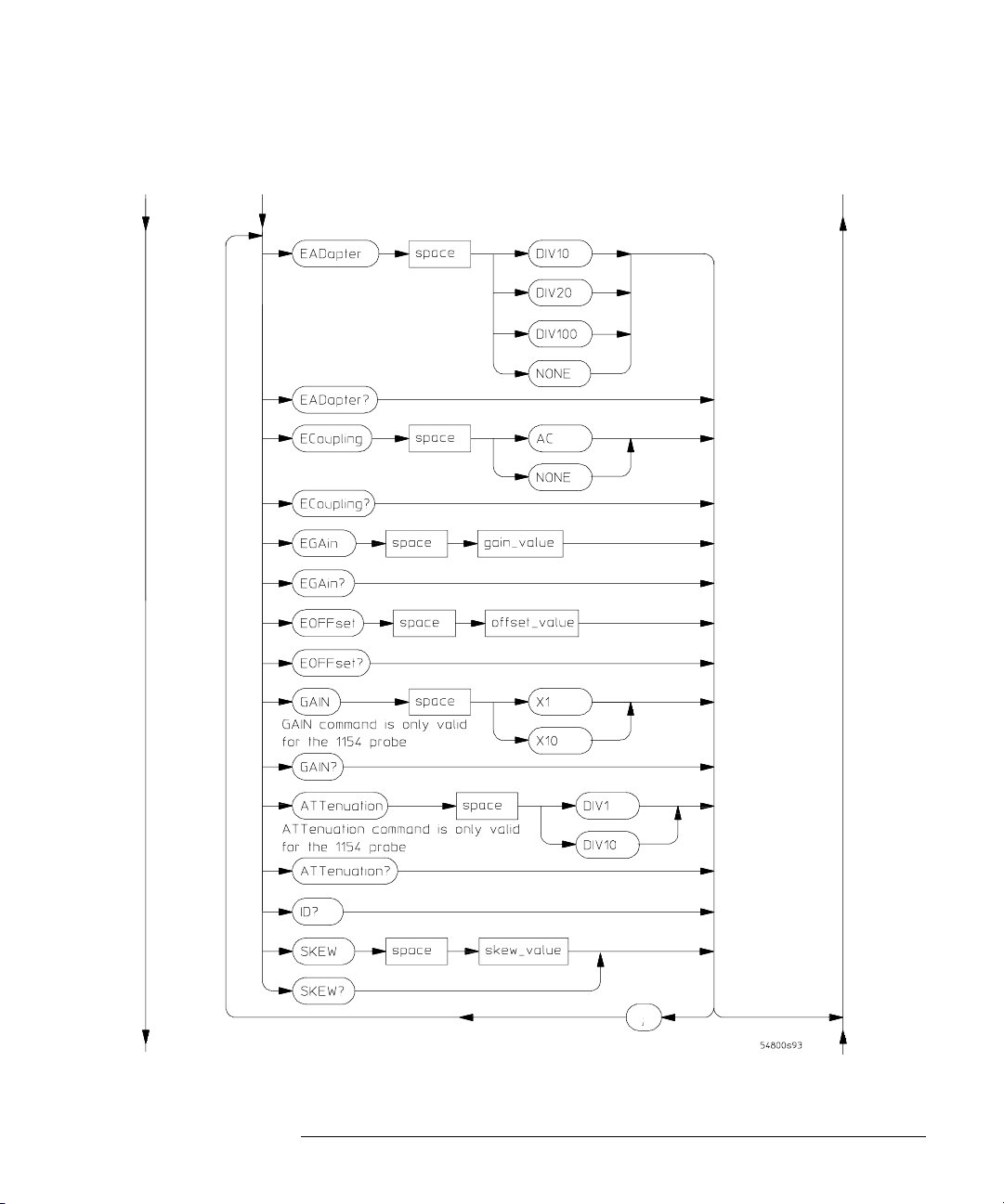
Figure 2-10
Command Syntax Diagrams
CHANnel Commands
CHANnel Commands Syntax Diagram (Continued)
2- 15
Page 42

Figure 2-11
Command Syntax Diagrams
CHANnel Commands
CHANnel Commands Syntax Diagram (Continued)
CHANnel Command Parameter Description
attenuation_factor A real number from 0.0001 to 1,000,000 (1.0E6), or -80 dB to 120 dB.
channel_number An integer, 1 or 2, for 54810 and 54820. An integer, 1 through 4, for all
gain_value A real number.
offset_value A real number.
position_value A real number.
range_value A real number.
scale_value A real number.
other Infiniium Oscilloscope models.
2- 16
Page 43

Command Syntax Diagrams
CHANnel Commands
CHANnel Command Parameter Description
attenuation_factor A real number from 0.0001 to 1,000,000 (1.0E6), or -80 dB to 120 dB.
skew_value A real number in the range of -100 µseconds to 100 µseconds.
2- 17
Page 44

Figure 2-12
Command Syntax Diagrams
DISK Commands
DISK Commands
DISK Commands Syntax Diagram
2- 18
Page 45
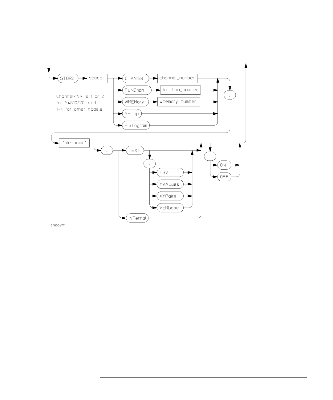
Figure 2-13
Command Syntax Diagrams
DISK Commands
DISK Commands Syntax Diagram (Continued)
DISK Command Parameter Description
channel_number An integer, 1 or 2, for 54810 and 54820. An integer,
1 through 4, for all other Infiniium Oscilloscope models.
"directory" A quoted string of characters.
"file_name" A quoted string of characters.
function_number, wmemory_number An integer, 1 through 4.
setup_number An integer, 0 through 9.
2- 19
Page 46

Figure 2-14
Command Syntax Diagrams
DISPlay Commands
DISPlay Commands
DISPlay Commands Syntax Diagram
2- 20
Page 47

Figure 2-15
Command Syntax Diagrams
DISPlay Commands
DISPlay Commands Syntax Diagram (Continued)
2- 21
Page 48
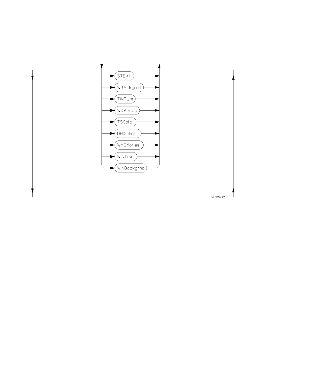
Figure 2-16
Command Syntax Diagrams
DISPlay Commands
DISPlay Commands Syntax Diagram (Continued)
2- 22
Page 49

Figure 2-17
Command Syntax Diagrams
DISPlay Commands
DISPlay Commands Syntax Diagram (Continued)
2- 23
Page 50

Figure 2-18
Command Syntax Diagrams
DISPlay Commands
DISPlay Commands Syntax Diagram (Continued)
2- 24
Page 51

Figure 2-19
Command Syntax Diagrams
DISPlay Commands
DISPlay Commands Syntax Diagram (Continued)
2- 25
Page 52

Command Syntax Diagrams
DISPlay Commands
Figure 2-20
DISPlay Commands Syntax Diagram (Continued)
DISPlay Command Parameter Description
color_name The name of a display color. See SCOLor for a list of color names.
column_number An integer, 0 to 81.
hue An integer, 0 to 100.
intensity_value An integer, 0 to 100.
luminosity An integer, 0 to 100.
persistence_value A real number, 0.1 to 40.
row_number An integer, 0 to 23.
saturation An integer, 0 to 100.
string_argument Any series of ASCII characters enclosed in quotation marks.
time An integer, 2 to 8.
2- 26
Page 53

Figure 2-21
Command Syntax Diagrams
EXTernal Channel Commands
EXTernal Channel Commands
External commands are only available in 2-channel Infiniium Oscilloscope
models, including the 54810A and 54820A.
EXTernal Commands Syntax Diagram
2- 27
Page 54

Figure 2-22
Command Syntax Diagrams
EXTernal Channel Commands
EXTernal Commands Syntax Diagram (Continued)
2- 28
Page 55

Figure 2-23
EXTernal Commands Syntax Diagram (Continued)
Command Syntax Diagrams
EXTernal Channel Commands
EXTernal Command Parameter Description
attenuation_factor A real number from 0.0001 to 1000000, and from -80 dB to 120 dB.
gain_value A real number.
offset_value A real number.
skew_value A real number from -100E-6 to 100E6.
2- 29
Page 56

Figure 2-24
Command Syntax Diagrams
FUNCtion Commands
FUNCtion Commands
channel_number is 1 or 2
for 54810/20 and 1 - 4 for
other models.
FUNCtion Commands Syntax Diagram
2- 30
Page 57

Figure 2-25
Command Syntax Diagrams
FUNCtion Commands
channel_number is 1 or 2
for 54810/20 and
1 - 4 for other models.
FUNCtion Commands Syntax Diagram (Continued)
2- 31
Page 58

Figure 2-26
Command Syntax Diagrams
FUNCtion Commands
FUNCtion Commands Syntax Diagram (Continued)
2- 32
Page 59

Figure 2-27
Command Syntax Diagrams
FUNCtion Commands
FUNCtion Commands Syntax Diagram (Continued)
FUNCtion Command Parameter Description
center_frequency_value A real number for frequency in Hertz, from -1E12 to 4E9.
channel_number An integer, 1 or 2, for 54810 and 54820. An integer,
function_number, wmemory_number An integer, 1 through 4.
float_value A real number from -1E6 to 1E6.
full_scale_range A real number for time or voltage range, from 10E-18 to 1E15.
offset_value A real number for vertical offset in the currently selected Y-axis units
position_value A real number for time of horizontal position, from -1E12 to 4E9.
range_value A real number for time of horizontal scale, from 1E-11 to 5E12.
1 through 4, for all other Infiniium Oscilloscope models.
(normally volts).
For :HORizontal:RANGe, this is the width of the screen in current x-axis
units (usually seconds).
2- 33
Page 60

Figure 2-28
Command Syntax Diagrams
HARDcopy Commands
HARDcopy Commands
HARDcopy Commands Syntax Diagram
HARDcopy Command Parameter Description
printer_number An integer.
printer_string A string representing the printer name.
2- 34
Page 61

Figure 2-29
Command Syntax Diagrams
HISTogram Commands
HISTogram Commands
HISTogram Commands Syntax Diagram
2- 35
Page 62

Command Syntax Diagrams
HISTogram Commands
HISTogram Command Parameter Description
channel_number An integer, 1 or 2, for 54810 and 54820. An integer,
1 through 4, for all other Infiniium Oscilloscope models.
function_number An integer, 1 through 4.
size The size is from 1.0 to 8.0 for the horizontal mode and from 1.0 to
10.0 for the vertical mode.
X1_position A real number for the X1 marker time value, in seconds.
X2_position A real number for the X2 marker time value, in seconds.
Y1_position A real number for the current measurement unit value
Y2_position A real number for the current measurement unit value
(volts, amps, watts, etc.).
(volts, amps, watts, etc.).
2- 36
Page 63

Figure 2-30
Command Syntax Diagrams
MARKer Commands
MARKer Commands
MARKer Commands Syntax Diagram
2- 37
Page 64

Figure 2-31
Command Syntax Diagrams
MARKer Commands
channel_number is 1 or 2
for 54810/20 and
1 - 4 for other models.
MARKer Commands Syntax Diagram (Continued)
2- 38
Page 65

Command Syntax Diagrams
MARKer Commands
MARKer Command Parameter Description
Ax_position A real number for the Ax marker time value, in seconds.
Bx_position A real number for the Bx marker time value, in seconds.
Ay_position A real number for the current measurement unit value
(volts, amps, watts, etc.).
By_position A real number for the current measurement unit value
(volts, amps, watts, etc.).
channel_number An integer, 1 or 2, for 54810 and 54820. An integer,
function_number, wmemory_number An integer, 1 through 4.
1 through 4, for all other Infiniium Oscilloscope models.
2- 39
Page 66

Figure 2-32
Command Syntax Diagrams
MEASure Commands
MEASure Commands
MEASure Commands Syntax Diagram
2- 40
Page 67

Figure 2-33
Command Syntax Diagrams
MEASure Commands
MEASure Commands Syntax Diagram (Continued)
2- 41
Page 68

Figure 2-34
Command Syntax Diagrams
MEASure Commands
MEASure Commands Syntax Diagram (Continued)
2- 42
Page 69

Figure 2-35
This command only
available on the 54845A
and 54846A
This command only
available on the 54845A
and 54846A
Command Syntax Diagrams
MEASure Commands
MEASure Commands Syntax Diagram (Continued)
2- 43
Page 70

Figure 2-36
Command Syntax Diagrams
MEASure Commands
channel_number is 1 or 2
for 54810/20 and
1 - 4 for other models.
MEASure Commands Syntax Diagram (Continued)
2- 44
Page 71

Figure 2-37
Command Syntax Diagrams
MEASure Commands
MEASure Commands Syntax Diagram (Continued)
2- 45
Page 72

Figure 2-38
Command Syntax Diagrams
MEASure Commands
MEASure Commands Syntax Diagram (Continued)
2- 46
Page 73

Figure 2-39
Command Syntax Diagrams
MEASure Commands
channel_number is 1 or 2
for 54810/20 and
1 - 4 for other models.
MEASure Commands Syntax Diagram (Continued)
2- 47
Page 74

Figure 2-40
channel_number is 1 or 2
for 54810/20 and
1 - 4 for other models.
Command Syntax Diagrams
MEASure Commands
MEASure Commands Syntax Diagram (Continued)
2- 48
Page 75

Command Syntax Diagrams
MEASure Commands
Figure 2-41
channel_number is 1 or 2
for 54810/20 and
1 - 4 for other models.
MEASure Commands Syntax Diagram (Continued)
MEASure Command Parameter Description
1st_peak_number An integer from 1 to 100,000 used to specify the number of the first peak.
2nd_peak_number An integer from 1 to 100,000 used to specify the number of the second peak.
channel_number An integer, 1 or 2, for 54810 and 54820. An integer, 1 through 4, for all other
Infiniium Oscilloscope models.
function_number, wmemory_number An integer, 1 to 4.
edge_direction RISing, FALLing, or EITHer.
edge_number An integer, 1 to 65534.
edge_position MIDDle, UPPer, or LOWer.
occurrence An integer, 1 to 65534.
percent An integer, -25 to 125.
slope + or -.
source CHANnel, FUNCtion, FFT, or WMEMory number.
start_edge_number An integer, 1 to 65534.
stop_edge_number An integer, 1 to 65534.
threshold_value A real number specifying the threshold for peaks.
time A real number specifying time.
top_voltage, base_voltage A real number.
upper_percent, middle_percent, lower_percent An integer from -25 to 125.
upper_voltage, middle_voltage, lower_voltage A real number.
voltage A real number specifying voltage.
2- 49
Page 76

Figure 2-42
Command Syntax Diagrams
Mask TESt Commands
Mask TESt Commands
Mask TESt Commands Syntax Diagram
2- 50
Page 77

Figure 2-43
Command Syntax Diagrams
Mask TESt Commands
Mask TESt Commands Syntax Diagram (Continued)
2- 51
Page 78

Figure 2-44
Command Syntax Diagrams
Mask TESt Commands
Mask TESt Commands Syntax Diagram (Continued)
2- 52
Page 79

Figure 2-45
Command Syntax Diagrams
Mask TESt Commands
Mask TESt Commands Syntax Diagram (Continued)
2- 53
Page 80

Figure 2-46
Command Syntax Diagrams
Mask TESt Commands
Mask TESt Commands Syntax Diagram (Continued)
2- 54
Page 81

Command Syntax Diagrams
Mask TESt Commands
Mask TESt Command Parameter Description
channel_number An integer, 1 or 2, for 54810 and 54820. An integer, 1 through 4, for all other
Infiniium Oscilloscope models.
count_value An integer 2 to 4096 specifying the number of data values to be averaged.
filename An MS-DOS compatible name of the file, a maximum of 254 characters long
(including the path name, if used).
function_number An integer from 1 to 4.
hamplitude_value A real number that represents the maximum amplitude, in volts, of a pulse.
lamplitude_value A real number that represents the minimum amplitude, in volts, of a pulse.
max_waveforms An integer 1 to 1,000,000,000.
memory_number An integer from 1 to 4.
region_number An integer, 1 through 8, designating the region for which you want to determine
the failure count.
stime_value An integer from 1 to 120 that represents the time-out value.
time_value A real number .0 to 1440.
xdelta_value A value for horizontal tolerance.
x1_value A time value specifying the location of the x1 coordinate, which will then be treated
as x=0 for mask regions coordinates.
ydelta_value A value for vertical tolerance.
y1_value A voltage value specifying the point at which y=0.
y2_value A voltage value specifying the location of the y2 marker.
2- 55
Page 82

Command Syntax Diagrams
SELFtest Commands
SELFtest Commands
Figure 2-47
channel_number is 1 or 2
for 54810/20 and
1 - 4 for other models.
SELFtest Commands Syntax Diagram
SELFtest Command Parameter Description
channel_number An integer, 1 or 2, for 54810 and 54820. An integer, 1 through 4, for all other
Infiniium Oscilloscope models.
2- 56
Page 83

Figure 2-48
Command Syntax Diagrams
TIMebase Commands
TIMebase Commands
TIMebase Commands Syntax Diagram
2- 57
Page 84

Command Syntax Diagrams
TIMebase Commands
TIMebase Command Parameter Description
delay_value A real number.
full_scale_range A real number. See the Infiniium Programmer’s Reference for
range values.
position_value A real number.
time A real number, in seconds per division.
2- 58
Page 85

Figure 2-49
Command Syntax Diagrams
TRIGger Commands
TRIGger Commands
See page 60
See page 61
See page 59
See page 59
See page 70
See page 65
See page 63
See page 64
See page 68
TRIGger Commands Syntax Overview
Figure 2-50
TRIGger Commands Syntax Diagram
See page 71
See page 71
See page 72
See page 73
See page 77
2- 59
Page 86
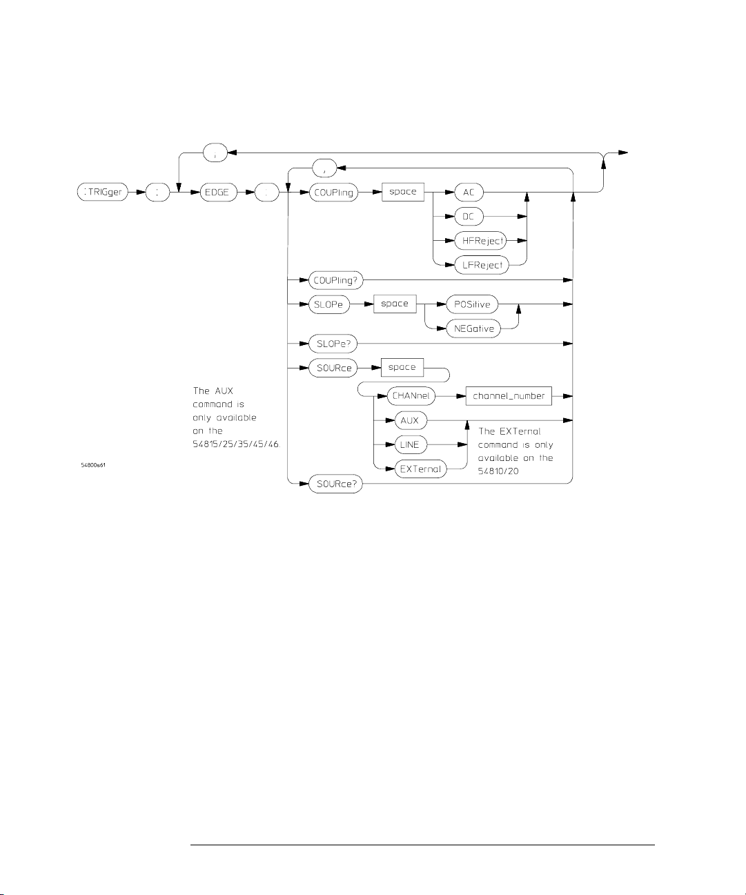
Figure 2-51
Command Syntax Diagrams
TRIGger Commands
channel_number is 1 or 2
for 54810/20 and
1 - 4 for other models.
TRIGger Commands Syntax Diagram (Continued)
2- 60
Page 87

Figure 2-52
Command Syntax Diagrams
TRIGger Commands
channel_number is 1 or 2
for 54810/20 and
1 - 4 for other models.
TRIGger Commands Syntax Diagram (Continued)
2- 61
Page 88

Figure 2-53
channel_number is 1
or 2 for 54810/20 and
1 - 4 for other models.
Command Syntax Diagrams
TRIGger Commands
TRIGger Commands Syntax Diagram (Continued)
2- 62
Page 89

Figure 2-54
TRIGger Commands Syntax Diagram (Continued)
Figure 2-55
Command Syntax Diagrams
TRIGger Commands
channel_number is 1 or 2
for 54810/20 and
1 - 4 for other models.
TRIGger Commands Syntax Diagram (Continued)
2- 63
Page 90

Figure 2-56
channel_number is
1 or 2 for 54810/20
and 1 - 4 for other
models.
Command Syntax Diagrams
TRIGger Commands
TRIGger Commands Syntax Diagram (Continued)
2- 64
Page 91

Figure 2-57
channel_number is 1 or 2
for 54810/20 and
1 - 4 for other models.
Command Syntax Diagrams
TRIGger Commands
TRIGger Commands Syntax Diagram (Continued)
Figure 2-58
TRIGger Commands Syntax Diagram (Continued)
channel_number is 1 or 2
for 54810/20 and
1 - 4 for other models.
2- 65
Page 92

Figure 2-59
Command Syntax Diagrams
TRIGger Commands
channel_number is 1 or 2
for 54810/20 and
1 - 4 for other models.
TRIGger Commands Syntax Diagram (Continued)
2- 66
Page 93

Figure 2-60
channel_number is 1 or 2
for 54810/20 and
1 - 4 for other models.
Command Syntax Diagrams
TRIGger Commands
TRIGger Commands Syntax Diagram (Continued)
2- 67
Page 94

Figure 2-61
Command Syntax Diagrams
TRIGger Commands
channel_number is 1 or 2
for 54810/20 and
1 - 4 for other models.
TRIGger Commands Syntax Diagram (Continued)
2- 68
Page 95

Figure 2-62
channel_number is 1 or 2
for 54810/20 and
1 - 4 for other models.
Command Syntax Diagrams
TRIGger Commands
TRIGger Commands Syntax Diagram (Continued)
2- 69
Page 96

Figure 2-63
Command Syntax Diagrams
TRIGger Commands
TRIGger Commands Syntax Diagram (Continued)
2- 70
Page 97

Figure 2-64
channel_number is 1 or 2
for 54810/20 and
1 - 4 for other models.
Command Syntax Diagrams
TRIGger Commands
Not all Infiniium oscilloscopes have
the RUNT triggering capability.
TRIGger Commands Syntax Diagram (Continued)
2- 71
Page 98

Figure 2-65
Command Syntax Diagrams
TRIGger Commands
channel_number is 1 or 2
for 54810/20 and
1 - 4 for other models.
TRIGger Commands Syntax Diagram (Continued)
2- 72
Page 99

Figure 2-66
channel_number is 1 or 2
for 54810/20 and
1 - 4 for other models.
Command Syntax Diagrams
TRIGger Commands
TRIGger Commands Syntax Diagram (Continued)
2- 73
Page 100

Figure 2-67
channel_number is 1 or 2
for 54810/20 and
1 - 4 for other models.
Command Syntax Diagrams
TRIGger Commands
TRIGger Commands Syntax Diagram (Continued)
2- 74
 Loading...