

Page 1

User’s Quick Start Guide
Publication number 54810-97045
January 2000
For Safety information, Warranties, and Regulatory information, see the pages
at the end of this manual.
© Copyright Agilent Technologies 1997-2000
All Rights Reserved
Infiniium Oscilloscopes
Page 2

In This Book
This book gives you the information you need to begin using the Infiniium
Oscilloscopes. It contains four chapters:
Setting up the Oscilloscope Chapter 1 contains inspection, power
requirements, air flow, and setup information.
Working in Comfort Chapter 2 contains recommendations for working
comfortably and safely while operating the Infiniium Oscilloscope.
Using the Oscilloscope Chapter 3 gives an overview of the front panel and
the graphical user interface, and tells you how to perform basic operations with
the oscilloscope.
Using the Built-In Information System Chapter 4 describes the built-in
information system contents and navigation. The built-in information system
contains all of the information that is generally found in a User’s Guide.
• For detailed information on how the oscilloscope makes measurements and
how to use the oscilloscope, see the built-in information system in the
oscilloscope.
• For information on programming the oscilloscope using a computer with a
GPIB interface card, see the Infiniium Oscilloscopes Programmer’s
Reference.
• For information on testing and servicing the oscilloscope, see either the
Infiniium Service Guide for Models 54810A/15A/20A/25A Oscilloscopes
or the Infiniium Service Guide for the Model 54835A and 54845A
Oscilloscope.
CAUTION The Infiniium Oscilloscope uses a specially designed Windows 98 application
program. While it is possible to access some standard Windows 98 application
programs, it is not recommended. All Infiniium Oscilloscope functionality is
directly available from within the Infiniium Oscilloscope application. Other
application software may or may not function correctly. Windows 98
configuration changes made outside of the Infiniium Oscilloscope application
may not work correctly and could cause improper operation of the instrument.
Page 3

Contents
Setting Up the Oscilloscope
To inspect package contents 1-3
To inspect options and accessories 1-5
To connect power 1-8
To connect the mouse or other pointing device 1-11
To attach the optional trackball 1-12
To connect the keyboard 1-17
To connect to the LAN card 1-18
!
To connect oscilloscope probes 1-19
To connect a printer 1-22
To connect an external monitor 1-24
To connect an GPIB cable 1-25
To tilt the oscilloscope upward for easier viewing 1-26
To turn on the oscilloscope 1-28
To turn off the oscilloscope 1-29
To verify basic oscilloscope operation 1-30
To clean the oscilloscope 1-32
Working in Comfort
About Repetitive Strain Injury 2-3
Mice and Other Input Devices 2-4
Using the Oscilloscope
To set the oscilloscope to a known starting condition 3-7
To start and stop waveform acquisition 3-8
To clear the waveform display 3-9
To turn a channel on or off 3-10
To change input impedance and input coupling 3-11
To adjust vertical scale and offset 3-12
To adjust sweep speed and horizontal position 3-13
To magnify a part of the waveform using delayed sweep 3-14
To set the oscilloscope to trigger on an edge 3-15
To use the markers 3-16
To use the quick measurements 3-17
To reinitialize the oscilloscope 3-18
To switch between the graphical interface and full-screen mode 3-30
To perform basic user interface operations 3-31
To select a command from the menu bar 3-33
To select a command from a context-sensitive menu 3-34
To change the mouse settings 3-36
To start and stop waveform acquisition 3-37
To clear the waveform display 3-38
To print the screen 3-39
Contents-1
Page 4

Contents
To turn a channel on or off 3-40
To adjust the vertical offset 3-41
To adjust vertical scaling 3-43
To access the channel setup 3-44
To set the horizontal reference point 3-45
To adjust sweep speed 3-46
To adjust horizontal position 3-47
To access the horizontal setup 3-48
To zoom on a section of the waveform 3-49
To move the markers using the graphical interface 3-51
To make a measurement on a waveform 3-52
To access the trigger setup 3-54
To set an edge trigger 3-55
To enable 8.0 GSa/s sampling mode on the 54845A 3-56
To enable 4.0 GSa/s sampling mode on the 54835A 3-57
To set dialog box preferences 3-58
To install the printer software 3-61
To set up the network 3-69
To recover your Infiniium hard disk 3-70
Using the Built-In Information System
To access the information system 4-4
To select the built-in information system language 4-10
To navigate through the information system 4-11
To access context-sensitive information 4-12
Contents-2
Page 5

1
Setting Up the Oscilloscope
Page 6

Setting Up the Oscilloscope
This chapter shows you how to set up your Infiniium oscilloscope,
connect power and accessories, and verify general operation.
1-2
Page 7

Setting Up the Oscilloscope
To inspect package contents
To inspect package contents
❏ Inspect the shipping container for damage.
Keep a damaged shipping container or cushioning material until you have
inspected the contents of the shipment for completeness and have checked the
oscilloscope mechanically and electrically.
❏ Verify that you received the following items in the Infiniium Oscilloscope
packaging.
• Infiniium Oscilloscope (54810A, 15A, 20A, 25A, 35A, or 45A)
• PS/2 Mouse, P/N C3751-60201
• Mouse Pad, P/N 54810-85901
• (2) 1160A 10:1 10-MΩ passive probes (54810A, 54820A)
• (4) 1160A 10:1 10-MΩ passive probes (54815A, 54825A)
• (4) 1161A 10:1 10-MΩ passive probes (54835A, 54845A)
• Accessory Pouch (P/N 54810-68701)
• Front Panel Cover
• Keyboard
•Power cord
• User’s Quick Start Guide
• Programmer’s Reference
• Programmer’s Quick Reference Guide
• Infiniium Service Guide for Models 54810A/15A/20A/25A Oscilloscopes
or Infiniium Service Guide for Model 54835A and 54845A Oscilloscope
See figure 1-1. (See table 1-3 for the power cord.) If anything is missing, contact
your nearest Agilent Technologies Sales Office. If the shipment was damaged,
contact the carrier, then contact the nearest Agilent Technologies Sales Office.
❏ Inspect the oscilloscope.
• If there is mechanical damage or a defect, or if the oscilloscope does not
operate properly or does not pass performance tests, notify your Agilent
Technologies Sales Office.
• If the shipping container is damaged, or the cushioning materials show signs
of stress, notify the carrier and your Agilent Technologies Sales Office. Keep
the shipping materials for the carrier’s inspection. The Agilent Technologies
Sales Office will arrange for repair or replacement at Agilent’s option without
waiting for claim settlement.
1-3
Page 8

Figure 1-1
Infiniium Oscilloscope
with Accessory Pouch
1160A or 1161A
Probe
Setting Up the Oscilloscope
To inspect package contents
Keyboard
PS/2 Mouse and
Mouse Pad
54810A/15A/20A/25A
Oscillo scopes Serv ice Guide
or 54835A and 54845A
Oscilloscope Service Guide
Infiniium Oscilloscopes
Programmer’s Reference
Package Contents for the Infiniium Oscilloscopes
1-4
Infiniium Oscilloscopes
User’s Quick Start Guide
Infiniium Oscilloscopes
Programmer’s Quick Reference
Page 9

Setting Up the Oscilloscope
To inspect options and accessories
To inspect options and accessories
❏ Verify that you received the options and accessories you ordered and that
none were damaged.
If anything is missing, contact your nearest Agilent Technologiess Sales Office.
If the shipment was damaged, or the cushioning materials show signs of stress,
contact the carrier and your Agilent Technologies Sales Office.
Some of the options available for the Infiniium Oscilloscopes are listed in table
1-1. Contact your Agilent Technologies Sales Office for a complete list of
options, or look in the built-in information system under the Accessories List.
Table 1-1
Infiniium Oscilloscope Options
Option Description
001 Additional set of standard probes—(2) 1160A probes for the
54810A/15A/20A/25A, or (2) 1161A probes for the 54835A and 54845A
002 Add 1 1162A 1:1 passive probe
003 Add 1 1163A 10:1 500006 Add one 1152A 2.5 GHz, 0.6-pF active probe (for the 54835A and 54845A only)
008 Add 1153A 200 MHz differential probe
009 Add 1154A 500 MHz differential probe
010 Add 1159A 1 GHz differential probe
015 Extended trigger for the 54810A, 54815A, 54820A, and 54825A
for the 54835A and 54845A, extended trigger comes as a standard part of the
oscilloscope
090 Delete standard probes
100 Telecommunications Mask Template Kit
106 BenchLink Scope Software (34810B version 1.6 or later)
200 VoiceControl
1BP MIL-STD-45662A and ANSI/NCSL Z-540 calibration with test data
1CM Add 1 Rackmount kit (E2609A)
AB0 Taiwan
AB1 Korea
AB2 PRC
ABD German
User’s Quick Start Guide
User’s Quick Start Guide
User’s Quick Start Guide
User’s Quick Start Guide
Ω, low-C passive probe
1-5
Page 10

Setting Up the Oscilloscope
To inspect options and accessories
Option Description
ABE Spanish
ABF French
ABJ Japanese
ABZ Italian
UL5 Add 1 Touchpad pointing device (E2612A)
UL6 Add 1 Clip-on trackball pointing device (E2611A)
W32 3 years calibration service
W34 3 years return standards comp calibration service
W50 5 years return repair service (additional 2 years)
W52 5 years return calibration service
W54 5 years return standards comp cal service
User’s Quick Start Guide
User’s Quick Start Guide
User’s Quick Start Guide
User’s Quick Start Guide
You can order multiple options with the oscilloscope. Also, all model numbers
shown in table 1-1 may also be ordered separately, using the model number.
Some accessories that will enhance your work with the oscilloscope are listed
in table 1-2.
Table 1-2
Accessories for the Infiniium Oscilloscopes
Agilent Model
Number
01144-61604 1:2 Probe Power Fan-Out (for use with 1144A and 1145A)
10020A Resistive Divider Probe Kit
10024A 16-pin IC clip
10076A 4 KV Passive Probe
10211A 24-pin IC clip
10240B BNC Blocking Capacitor
10450A SMT Probe Accessory Kit
10833A GPIB cable, 1 m
10833B GPIB cable, 2 m
10833C GPIB cable, 4 m
10833D GPIB cable, 0.5 m
11094B 75
1142A Probe control and power module
Description
Ω Feedthrough Termination
1-6
Page 11

Setting Up the Oscilloscope
To inspect options and accessories
Agilent Model
Number
1182A Testmobile
1250-2427 PC Board Mini-Probe Socket (horizontal mount)
1250-2428 PC Board Mini-Probe Socket (vertical mount)
34398A
34399A
54006A 6 GHz probe, 10:1 (500
54701A 2.5 GHz probe, 10:1, 100 k
C2950A Parallel printer cable, 2 m
C2951A Parallel printer cable, 3 m
1144A 800 MHz Active Probe
1145A 2-channel, 750 MHz SMT active probe
1146A AC/DC Current Probe
1152A 2.5 GHz Active Probe
1153A 200 MHz Differential Probe
1154A 500 MHz Differential Probe
1155A 750 MHz 2-Channel, Low-Mass Active Probe
1159A 1 GHz Differential Probe
1170A 500 MHz Low-Mass, Miniature 10:1 10 M
1171A 500 MHz Low-Mass, Miniature 10:1 10 M
1172A 500 MHz Low-Mass, Miniature 20:1 10 M
1173A 500 MHz Low-Mass, Miniature 20:1 10 M
1250-1454 BNC to Miniature Probe Adapter
E2621A 75
E2622A 100/110/120
E2625A Telecommunications Mask Template Kit
E2635A VoiceControl Retrofit Kit
Description
RS-232-C printer cable
RS-232-C Adapter kit
Ω) or 20:1 (1 kΩ), .25 pf
Ω, 0.6 pf Active Probe (need 1143A probe
power)
Requires 1142A power supply—1144-61604 probe power extender also
required when using more than two 1144A active probes
Requires 1142A power supply
Ω Passive Probe
Ω Passive Probe
Ω Passive Probe
Ω Passive Probe
Ω terminator
Ω differential terminator
1-7
Page 12

Figure 1-2
Setting Up the Oscilloscope
To connect power
To connect power
1 Position the oscilloscope where it will have sufficient clearance for
airflow around the top, back, and sides.
Minimum 0 mm
Minimum 15.9 mm
Minimum 15.9 mm
both sides
Airflow requirements
54810A-25A 125 cfm
54835A-45A 250 cfm
Positioning the Infiniium Oscilloscope with Sufficient Clearance
Minimum 38.1 mm
1-8
Page 13

Figure 1-3
Setting Up the Oscilloscope
To connect power
2 Connect the power cord to the rear of the oscilloscope, then to a
suitable ac voltage source (100-240 VAC ±10%, 47 to 440 Hz, max power
dissipation 390 W).
Infiniium Oscilloscope Power Cord Connection
The oscilloscope power supply automatically adjusts for line input voltages in
the range 100 to 240 VAC. Therefore, you do not need to adjust an input line
voltage setting. The line cord provided is matched by Agilent Technologies to
the country of origin of the order.
3 Ensure that you have the correct line cord. See table 1-3.
1-9
Page 14

Setting Up the Oscilloscope
To connect power
Table 1-3
Power Cords
Plug Type Cable Part
No.
250V 8120-1351
8120-1703
Plug Description Length
Straight *BS1363A
90°
(in/cm)
90/228
90/228
Color Country
Gray
Mint Gray
United Kingdom,
Cyprus, Nigeria,
Zimbabwe, Singapore
250V 8120-1369
8120-0696
250V 8120-1689
8120-1692
8120-2857
125V 8120-1378
8120-1521
8120-1992
250V 8120-2104
8120-2296
220V 8120-2956
8120-2957
250V 8120-4211
8120-4600
100V 8120-4753
8120-4754
* Part nu mber show n for plug is the indust ry identifi er for the plug only. Numb er shown fo r cable is the Agilent p art number for the complete
cable including the plug.
Straight *NZSS198/ASC
90°
Straight *CEE7-Y11
90°
Straight (Shielded)
Straight *NEMA5-15P
90°
Straight (Medical) UL544
Straight *SEV1011
1959-24507
Type 12 90°
Straight *DHCK107
90°
Straight SABS164
90°
Straight MITI
90°
79/200
87/221
79/200
79/200
79/200
90/228
90/228
96/244
79/200
79/200
79/200
79/200
79/200
79/200
90/230
90/230
Gray
Mint Gray
Mint Gray
Mint Gray
Coco Brown
Jade Gray
Jade Gray
Black
Mint Gray
Mint Gray
Mint Gray
Mint Gray
Jade Gray Republic of South
Dark Gray Japan
Australia, New
Zealand
East and West
Europe, Saudi Arabia,
So. Africa, India
(unpolarized in many
nations)
United States,
Canada, Mexico,
Philippines, Taiwan
Switzerland
Denmark
Africa
India
1-10
Page 15
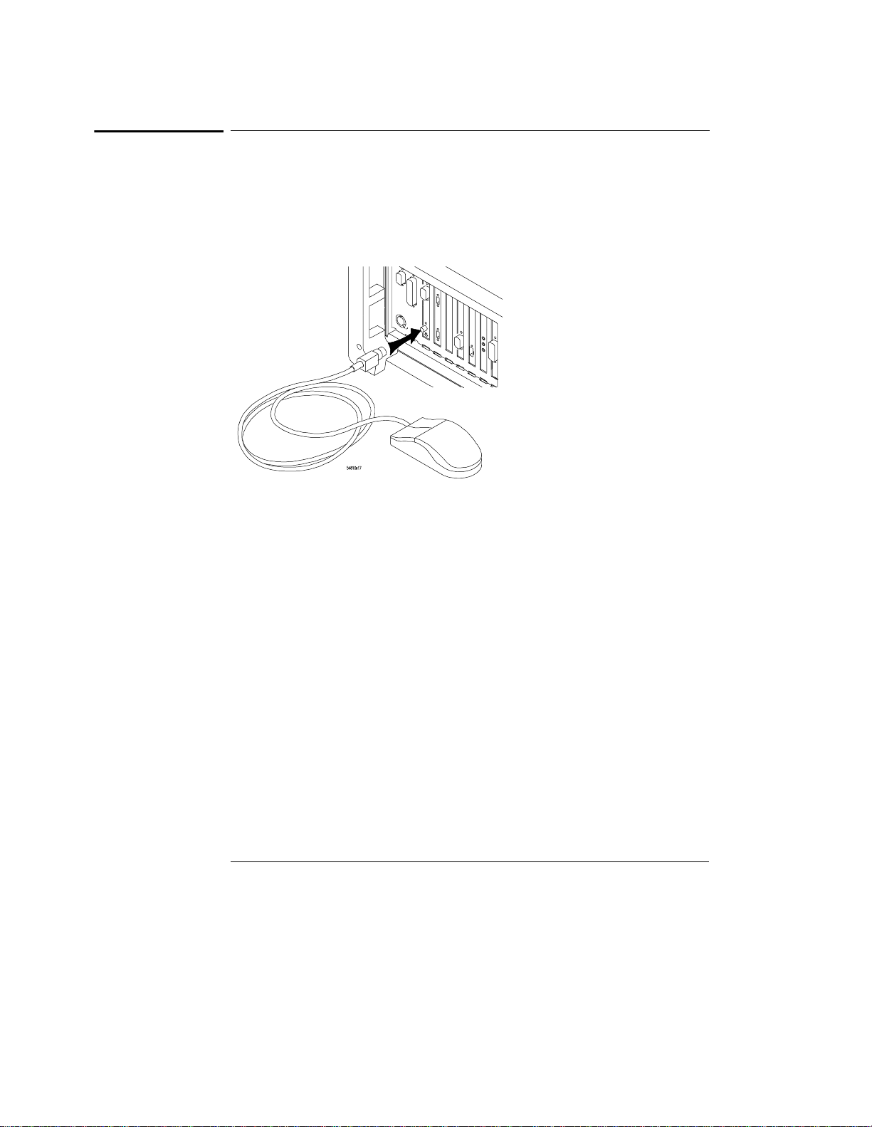
Figure 1-4
Setting Up the Oscilloscope
To connect the mouse or other pointing device
To connect the mouse or other pointing device
1 Plug the mouse into the matching connector on the back panel of the
oscilloscope.
Connecting the Mouse Cable
While you can operate many oscilloscope functions using only the front-panel
keys and knobs, you will need the mouse to access advanced oscilloscope
functions through the graphical interface, or to find out more about the
oscilloscope through the built-in information system.
The optional touchpad pointing device connects in exactly the same way as the
mouse. The supplied mousepad provides the correct surface for smooth mouse
operation.
2 To modify the mouse configuration, see “To change the mouse settings”
in Chapter 3.
1-11
Page 16

Figure 1-5
Setting Up the Oscilloscope
To attach the optional trackball
To attach the optional trackball
1 Push in the latch on the trackball baseplate to extend the metal tabs.
Insert the tabs into the upper right of the slot on the side of the
oscilloscope. You can only install the trackball on the right side
of the oscilloscope.
Connecting the Trackball Baseplate
1-12
Page 17
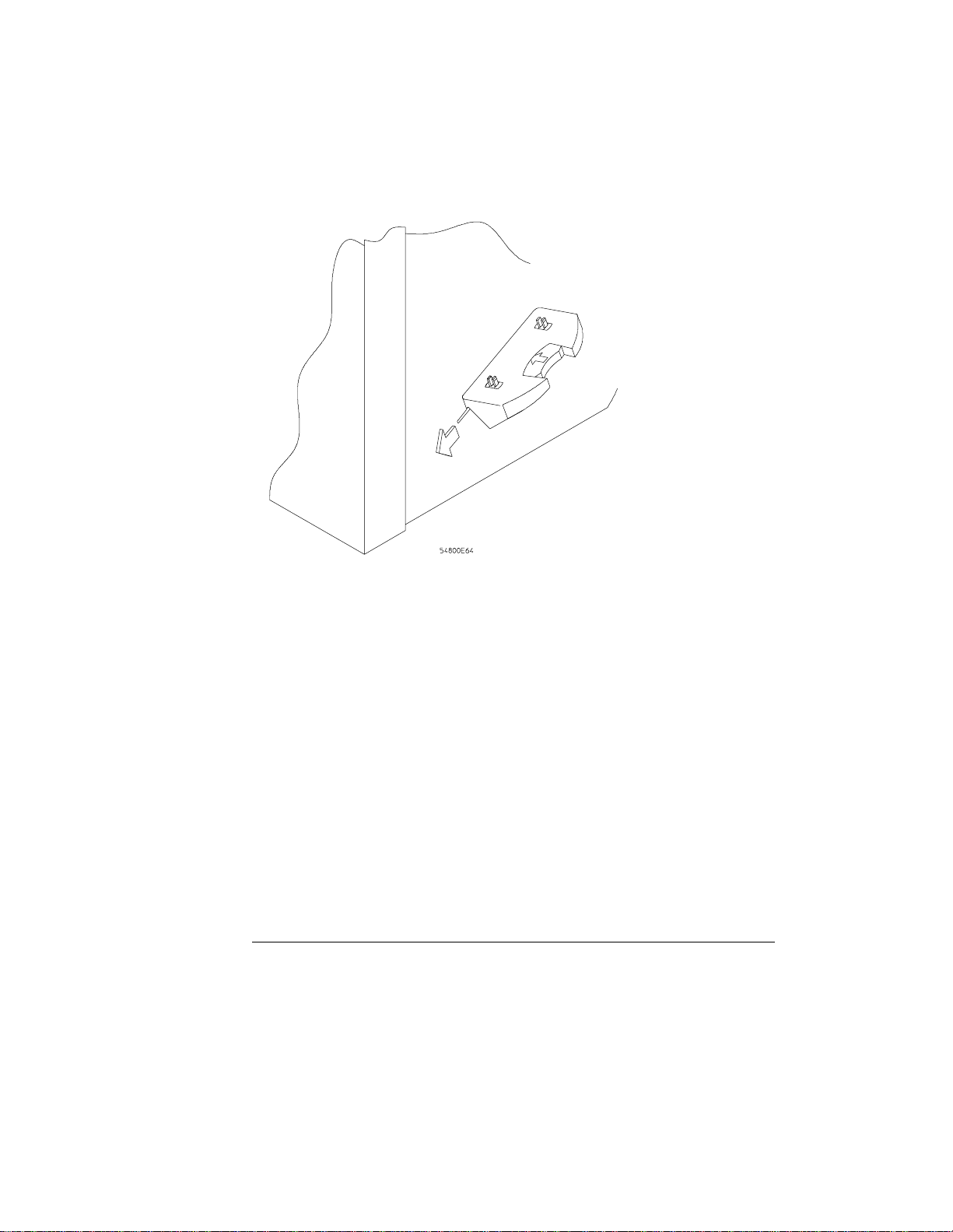
Figure 1-6
Setting Up the Oscilloscope
To attach the optional trackball
2 While holding the latch in, slide the metal tabs down and to the front of
the oscilloscope until they touch the ends of the slot.
Slide the Metal Tabs
1-13
Page 18
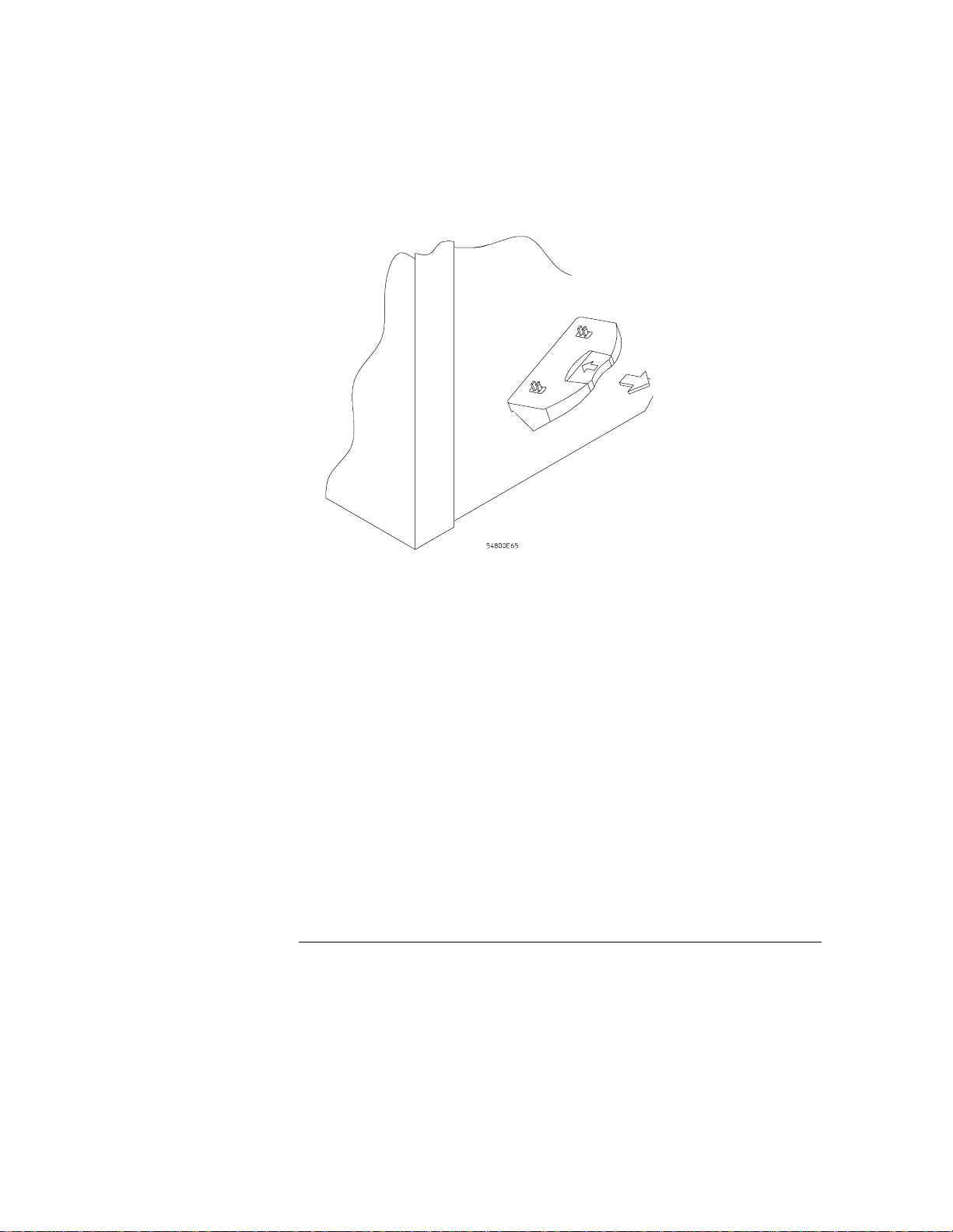
Figure 1-7
Setting Up the Oscilloscope
To attach the optional trackball
3 Release the latch. The trackball baseplate should now be secure
against the side of the oscilloscope.
Trackball Baseplate Secured
1-14
Page 19

Figure 1-8
Setting Up the Oscilloscope
To attach the optional trackball
4 Snap the trackball assembly onto the pins of the baseplate. The
trackball and buttons should face up and toward the front of the
oscilloscope.
Snap the Trackball Assembly Onto the Baseplate
1-15
Page 20

Figure 1-9
Setting Up the Oscilloscope
To attach the optional trackball
5 Connect the 9-pin “D” connector on the trackball cable to the COM1
port on the back panel. Tighten the retaining screws.
Connecting the Trackball Cable to the COM1 Port
For information on changing the trackball settings, see “To change the mouse
settings” in Chapter 3.
1-16
Page 21

Figure 1-10
Setting Up the Oscilloscope
To connect the keyboard
To connect the keyboard
1 Plug the keyboard cable into the matching connector on the back panel
of the oscilloscope.
Connecting the Keyboard
The keyboard simplifies some oscilloscope tasks, such as entering file names
when you store waveforms and setups to the disk.
2 If you need more desk space, place the keyboard on top of the
oscilloscope. Do not stack other objects on the keyboard; this will
cause self-test failures on power on.
1-17
Page 22

Figure 1-11
RJ-45
Connection
Setting Up the Oscilloscope
To connect to the LAN card
To connect to the LAN card
1 Connect your LAN cable to the RJ-45 connector on the LAN card. Make
sure the connection is secure.
Connecting to the LAN Card
2 After you have connected to the LAN card, you must set up the network.
Each Infiniium Oscilloscope now ships with a LAN card installed. If you want
a LAN connection, but have an older Infiniium Oscilloscope model that does not
have a LAN card installed, contact your Agilent Technologies Sales and Service
Office. A LAN Card Installation Kit with instructions is available from Agilent
Technologies and describes how to add a LAN card to your Infiniium
Oscilloscope.
Go to “To set up the network” in chapter 3.
1-18
Page 23

Figure 1-12
Setting Up the Oscilloscope
To connect oscilloscope probes
To connect oscilloscope probes
1 Attach the probe connector to the desired oscilloscope channel or
trigger input. Push it straight on until it latches into place.
Attaching the Probe Connector
1-19
Page 24

Figure 1-13
Setting Up the Oscilloscope
To connect oscilloscope probes
2 Connect the probe to the circuit of interest using grabbers or other
probing aids.
Probing the Circuit
1-20
Page 25

Figure 1-14
Setting Up the Oscilloscope
To connect oscilloscope probes
3 To disconnect the probe, push the small latch on top of the probe
connector to the left, then pull the connector body away from the front
panel of the oscilloscope without twisting it.
Disconnecting the Oscilloscope Probe
CAUTION Do not attempt to twist the snap-on probes on or off the oscilloscope’s BNC
connector. Twisting the probe connector body will damage it.
CAUTION Do not exceed the maximum input voltage rating! The maximum input voltage
!
for 50 Ω inputs is 5 Vrms, CAT I. Maximum voltage for the 54810A/15A/20A/
25A at 1 MΩ input impedance is ±250V (dc + ac) [ac < 10 kHz], CAT I; for the
54835A and 54845A it is ±100V (dc + ac) [ac < 10 kHz], CAT I.
1-21
Page 26

Figure 1-15
Setting Up the Oscilloscope
To connect a printer
To connect a printer
If you have a parallel (Centronics) printer, you will need a parallel printer cable,
such as an C2950A (2 m) or C2951A (3 m) cable. Go to step 1.
If you have a serial printer, you will need a 9-pin to 25-pin serial printer cable,
such as an 34398A cable, plus the 34399A adapter kit. Some printers may
require other cable configurations, but the oscilloscope has a 9-pin serial
connector. Go to step 5.
1 Attach the 25-pin small “D” connector to the printer output connector
on the rear of the oscilloscope. Tighten the thumbscrews to secure the
cable.
Attaching the Small “D” Connector
2 Attach the larger 36-pin “D” connector to the printer. Latch the wire
bails into the tabs on each side of the connector.
Figure 1-16
Attaching the Larger “D” Connector
1-22
Port on Printer
Page 27
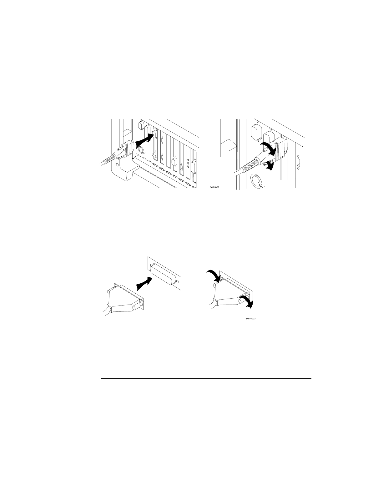
Figure 1-17
Setting Up the Oscilloscope
To connect a printer
3 Set the printer configuration to use the “Centronics” or “Parallel”
interface, if necessary. See the documentation for your printer.
4 Go to “To install the printer software” in Chapter 3.
5 Connect the 9-pin “D” connector of the serial printer cable to the serial
output port on the rear panel of the oscilloscope. Tighten the
thumbscrews to secure the cable.
Figure 1-18
Attaching the 9-pin “D” Connector
6 Attach the 25-pin “D” connector to the serial input port of the printer.
Tighten the thumbscrews to secure the cable.
Port on Printer
Attaching the 25-pin “D” Connector
7 Set the printer configuration to use the serial interface. See the
documentation for your printer.
8 Go to “To install the printer software” in Chapter 3.
1-23
Page 28

Figure 1-19
Setting Up the Oscilloscope
To connect an external monitor
To connect an external monitor
You can connect a VGA-compatible monitor to the Infiniium oscilloscope to
provide a larger viewing area.
1 Connect the monitor cable to the display board video connector at the
rear panel of the oscilloscope.
2 Tighten the retaining screws.
Connecting an External Monitor
1-24
Page 29

Figure 1-20
Setting Up the Oscilloscope
To connect an GPIB cable
To connect an GPIB cable
1 Attach the GPIB connector to the GPIB interface card connector at the
rear of the oscilloscope.
2 Tighten the thumbscrews on the connector.
Attaching the GPIB Connector
1-25
Page 30
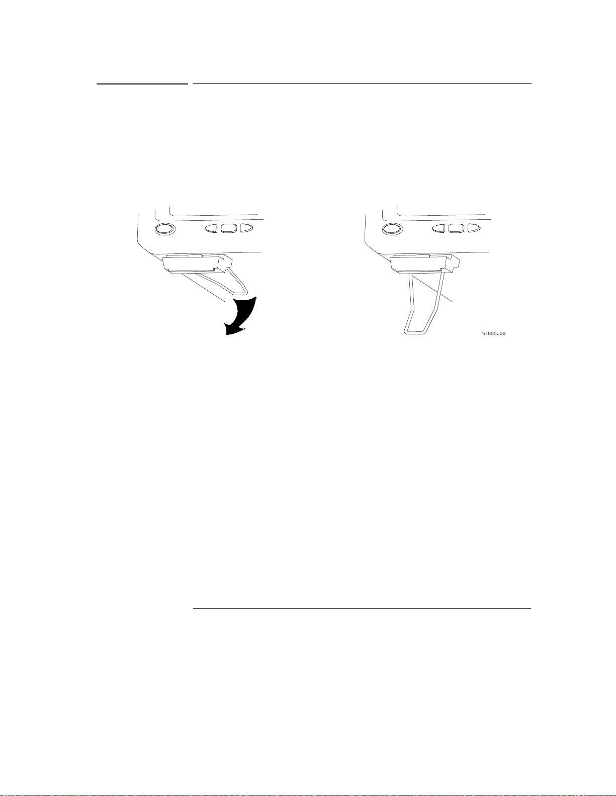
Figure 1-21
Setting Up the Oscilloscope
To tilt the oscilloscope upward for easier viewing
To tilt the oscilloscope upward for easier viewing
1 If your oscilloscope has front feet with individual wire bails, lift up the
front of the oscilloscope, grasp one of the wire bails under the front
corner, and pull it down and forward until it latches into place. Repeat
for the other wire bail.
Tilting the Oscilloscope
1-26
Page 31

Figure 1-22
Setting Up the Oscilloscope
To tilt the oscilloscope upward for easier viewing
2 If your oscilloscope has front feet with a wire bail between the two feet,
lift up the front of the oscilloscope, grasp the bail near the center, and
pull it down and forward until it latches into place.
Latching the Oscilloscope Front Feet
1-27
Page 32
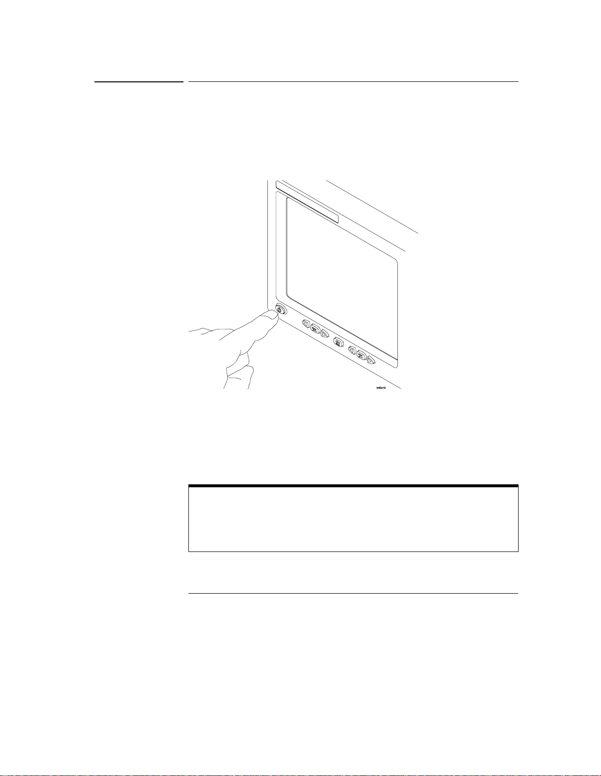
Figure 1-23
Setting Up the Oscilloscope
To turn on the oscilloscope
To turn on the oscilloscope
1 Depress the power switch in the lower left-hand corner of the
oscilloscope front panel.
Turning on the Oscilloscope
After a short initialization period, the oscilloscope display appears. The
oscilloscope is ready to use.
2 Hook up all cables and accessories before applying power. You can
connect and disconnect probes and the keyboard while the oscilloscope
is turned on.
Screen Saver
The oscilloscope display has a screen saver that turns off the backlight when there
has been no front panel or graphical interface activity for a pre-determined period.
The default time is 8 hours and is configurable through the Display Setup dialog in
the graphical interface. You can turn the display on by moving the mouse, typing on
the optional keyboard, pressing a front panel key, or turning a front panel knob.
1-28
Page 33

Setting Up the Oscilloscope
To turn off the oscilloscope
To turn off the oscilloscope
1 Depress the power switch at the lower left-hand corner of the
oscilloscope front panel.
Even though the Infiniium oscilloscope is based on the Windows 98 operating
system, shuting down the oscilloscope without going through the normal Windows
98 shutdown process is perfectly safe. The Infiniium oscilloscope software was
designed making sure not to do anything which requires going through a normal
shutdown.
1-29
Page 34
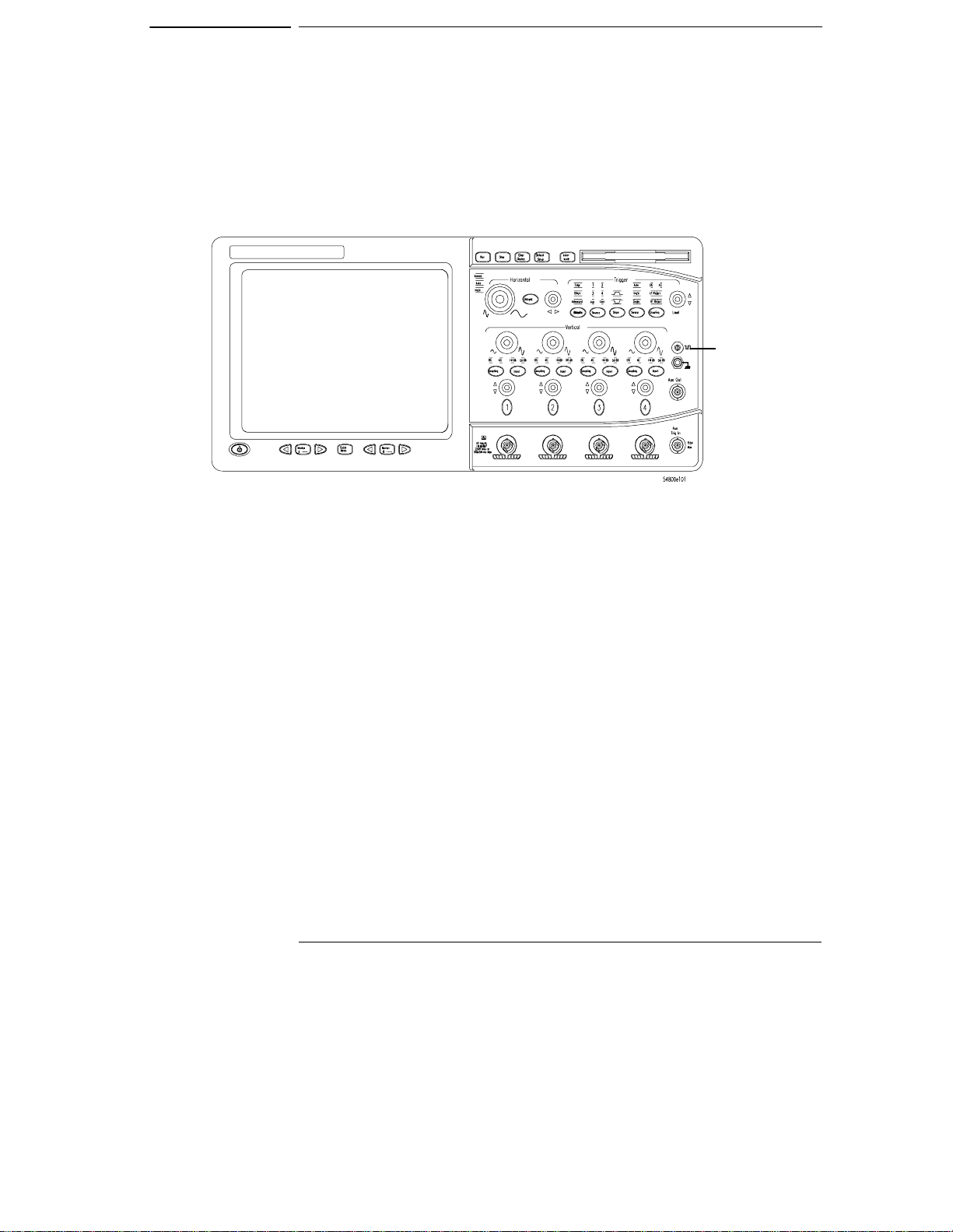
To verify basic oscilloscope operation
1 Connect an oscilloscope probe to channel 1.
2 Attach the probe to the calibration output on the front panel of the
oscilloscope.
Use a probe grabber tip so you do not need to hold the probe. The calibration
output is marked with a square wave symbol.
Figure 1-24
Verifying Basic Oscilloscope Operation
Calibration
Output
3 Press the Default Setup key on the front panel.
The display will pause momentarily while the oscilloscope is configured to its
default settings.
4 Press the Autoscale key on the front panel.
The display will pause momentarily while the oscilloscope adjusts the sweep
speed and vertical scale. You should then see a square wave with peak-to-peak
amplitude of approximately 5 divisions and a period of almost 3 divisions. If you
do not see the waveform, ensure your power source is adequate, the
oscilloscope is properly powered-on, and the probe is connected securely to the
front-panel channel input BNC and to the probe calibration output.
1-30
Page 35

Figure 1-25
Setting Up the Oscilloscope
To verify basic oscilloscope operation
5 Move the mouse pointer to the graphical interface enable button and
click once using the left mouse button.
The graphical interface enable button is in the upper-right corner of the display.
6 Move the mouse around the mouse pad and verify that the pointer
follows on the screen.
If the pointer does not move, ensure that the mouse is properly connected, that
you have clicked the correct button to enable the graphical interface, and that
the mouse is on a medium-friction surface such as the mouse pad supplied with
the oscilloscope.
With the mouse pointer
on the right-hand button,
click the mouse to
enable the graphical
interface
Graphical Interface Enable Button
1-31
Page 36

Setting Up the Oscilloscope
To clean the oscilloscope
To clean the oscilloscope
• Clean the oscilloscope with a soft cloth dampened with a mild soap and
water solution.
CAUTION Do not use too much liquid in cleaning the oscilloscope. Water can enter the
Infiniium front panel, damaging sensitive electronic components.
1-32
Page 37

2
Working in Comfort
Page 38

Introduction
To optimize your comfort and productivity, it is important that you set
up your work area correctly and use your Infiniium oscilloscope properly.
With that in mind, we have developed some set-up and use
recommendations for you to follow based on established ergonomic
principles.
Improper and prolonged use of keyboards and input devices are among
those tasks that have been associated with repetitive strain injury (RSI)
to soft tissues in the hands and arms. If you experience discomfort or
pain while using the oscilloscope, discontinue use immediately and
consult your physician as soon as possible. For more information on RSI
you may wish to consult the About Repetitive Strain Injury section.
Please study the recommendations offered here in this chapter.
Included there are references to relevant parts of international
standards, regulations and guidelines, such as ISO 9241 and the
European Community Display Screen Equipment directive. You may
also wish to consult your employer’s human resources department or
other relevant departments for guidance specific to your company.
2-2
Page 39

Working in Comfort
About Repetitive Strain Injury
About Repetitive Strain Injury
Because your comfort and safety are our primary concern, we strongly
recommend that you use the Infiniium oscilloscope in accordance with
established ergonomic principles and recommendations. Scientific literature
suggests that there may be a relationship between injury to soft tissues—
especially in the hands and arms—and prolonged improper use of keyboards or
other equipment requiring repeated motions of the hands and forearms. This
literature also suggests that there are many other risk factors that may increase
the chance of such injury, commonly called Repetitive Strain Injury.
What is RSI? Repetitive Strain Injury (RSI—also known as cumulative trauma disorder or
repetitive motion injury) is a type of injury where soft tissues in the body, such
as muscles, nerves, or tendons, become irritated or inflamed. RSI has been a
reported problem for those who perform repetitive tasks such as assembly line
work, meatpacking, sewing, playing musical instruments, and computer work.
RSI also has been observed in those who frequently engage in activities such as
carpentry, knitting, housework, gardening, tennis, windsurfing and lifting
children.
What causes RSI? The specific causes of RSI have not been established. Nevertheless, the
incidence of RSI has been associated with a variety of risk factors, including:
• Too many uninterrupted repetitions of an activity or motion.
• Performing an activity in an awkward or unnatural posture.
• Maintaining static posture for prolonged periods.
• Failing to take frequent short breaks.
• Other environmental and psychosocial factors.
In addition, there have been reports associating the occurrence of RSI with the
use of keyboards, mice, and other input devices. Also, certain medical
conditions, such as rheumatoid arthritis, obesity and diabetes, may predispose
some people to this type of injury.
What if I experience
discomfort? If you are experiencing any discomfort, seek professional medical advice
immediately. Typically, the earlier a problem is diagnosed and treated, the easier
it is to resolve.
2-3
Page 40

Working in Comfort
Mice and Other Input Devices
Mice and Other Input Devices
Various aspects of using mice and other input devices may increase your risk of
discomfort or injury. Observing the following recommendations may reduce
that risk.
• Try to keep your hand, wrist, and forearm in a neutral position while using
your mouse or other input device.
• If you use your thumb to rotate the ball on a trackball or spaceball, keep it
in a relaxed, natural shape, and maintain a neutral posture in your hand,
wrist, and forearm.
• Hold the mouse gently by draping your fingers over it. Keep your hand
relaxed and fingers loose. Do not grip the mouse tightly.
• It takes very little pressure or force from your fingers to activate the buttons
or scroll wheel on your mouse, scrolling mouse, trackball, or other input
device. Using too much force can place unnecessary stress on the tendons
and muscles in your hands, wrists, and forearms.
• If you are using a scrolling mouse, be sure to keep your fingers and hand in
a relaxed, neutral position when activating the scroll wheel. Also, this type
of mouse features software that can minimize the number of mouse
movements or button clicks.
• When using a mouse, trackball, or other input device, position it as close to
the keyboard as possible, and keep it at the same level as you do not have to
stretch while using it.
• Use a good quality mouse pad to enable the mouse to work most effectively
and reduce unnecessary hand and wrist movements.
• Be sure to keep your mouse and trackball clean. Regular removal of
accumulated dust and dirt helps ensure proper tracking and reduces
unnecessary hand and wrist motions.
2-4
Page 41

3
Using the Oscilloscope
Page 42

Using the Oscilloscope
The Infiniium Oscilloscope is designed to be easy to use.
• The familiar front-panel oscilloscope interface with knobs and keys is
optimized for the most common kinds of troubleshooting tasks and
basic measurements. See “Using the Front Panel” on page 3-3.
• The graphical interface with menus, windows, dialogs, and toolbars
provides easy logical access to dozens of configuration and analysis
tools, making it easy for you to set up and make the most complex
measurements. The interface also allows you to use the Infiniium
oscilloscope’s built-in information system, which gives detailed
information on using the oscilloscope to make measurements. See
“Using the Graphical Interface” on page 3-19.
3-2
Page 43

Using the Front Panel
The Infiniium Oscilloscope front panel has been designed to give you
direct access to the functions needed to perform the most common
measurements needed in troubleshooting, using a traditional
oscilloscope interface. Knobs and keys are included to enable direct
setting of vertical and horizontal parameters. In addition, the front panel
has a set of LED (Light-Emitting Diode) indicators; by using these and
the display, you can assess the configuration of the oscilloscope at a
glance—there is no need to enter a series of keystrokes to navigate
through complex menus.
The Infiniium Oscilloscope uses color consistently throughout the front
panel and user interface. For example, the color of the knob for channel
1 is the same color as the waveform for channel 1. All the configuration
items and values related to channel 1 are displayed in the same color.
3-3
Page 44

Figure 3-1
Using the Oscilloscope
Front Panel
Figure 3-1 shows the Infiniium Oscilloscope front panel.
Horizontal
controls
Acquisition and
general controls
Trigger
controls
Power Switch
Infiniium Oscilloscope Front Panel
Using the front panel, you can configure the Infiniium Oscilloscope for
most troubleshooting tasks. The control categories are:
• Acquisition and general controls
• Horizontal controls
• Trigger controls
• Vertical controls
• Marker and measurement controls
3-4
Marker and
Measurement Controls
Vertical controls
Page 45

Using the Oscilloscope
Acquisition and General Controls
Using the acquisition and general controls, you control whether the
oscilloscope is running or stopped. Other keys allow you to reset the
oscilloscope to its factory default setup, automatically configure the
oscilloscope for the current input signals (Autoscale), or erase the
waveforms from the display.
Horizontal Controls
Using the horizontal controls, you configure the oscilloscope’s sweep
speed (seconds per division) and horizontal position of the waveform.
You can also view a magnified section of the waveform using the delayed
sweep window, which uses software to expand part of the acquisition
memory.
Trigger Controls
Using the trigger controls, you set the conditions on which the
oscilloscope will trigger and acquire an input signal. You can set up a
variety of trigger conditions. Edge and glitch triggers can be selected
from the front panel, and the parameters for edge triggering can be set
up here as well. Some glitch trigger parameters (such as glitch width)
and all advanced trigger configurations are set up using the graphical
interface.
Trigger configuration settings you make using the graphical interface are
reflected in the front-panel status indicators, and will remain set unless
you change them (either using the front panel or the graphical interface)
or press the Default Setup key. See “Using the Graphical Interface” on
page 3-19 for information on accessing the graphical interface.
Vertical Controls
Using the vertical controls, you set the vertical scaling (volts per
division), vertical offset, input impedance, and input coupling. You can
also turn the display on or off for a particular channel.
3-5
Page 46

Using the Oscilloscope
Marker and Measurement Controls
Using the marker and measurement controls, you control two sets of
markers within the oscilloscope graticule. You use markers to make
more accurate measurements of waveform events than you could make
visually. Both time and voltage differences between the markers are
updated continuously on the screen. By default, the markers track the
source waveform. Voltage measurements from the markers are the value
of the waveform at the time set with the marker arrow keys.
The QuickMeas key initiates four preset measurements on the
waveforms. Both quick measurements and markers will function on any
input waveform; simply continue to press and release one of the keys
(either QuickMeas, Marker A, or Marker B) to cycle through all the
waveforms on the screen, then to the off state. You choose which four
measurements will be performed by using the measurement
configuration commands in the graphical interface.
3-6
Page 47

Using the Oscilloscope
To set the oscilloscope to a known starting condition
To set the oscilloscope to a known starting condition
• Press the Default Setup key.
You can set up the oscilloscope for many different kinds of complex
measurements. To easily reset the oscilloscope to a known measurement
configuration, use the Default Setup key.
If you use the Default Setup key with the graphical interface enabled, you can
select Undo Default Setup from the Control menu to return the oscilloscope to
its original configuration.
Save the Current Oscilloscope Configuration
Before using Default Setup, you may want to save the current oscilloscope
configuration for later use. See the built-in information system (described in chapter
4) for instructions on saving and recalling setups, and for information on the exact
configuration that is set when you press Default Setup.
3-7
Page 48

Figure 3-2
Using the Oscilloscope
To start and stop waveform acquisition
To start and stop waveform acquisition
• To start waveform acquisition, press the Run key.
The oscilloscope begins acquiring data. When it receives a trigger signal, it
finishes acquiring data, updates the display, then starts another acquisition
cycle if it is in triggered or auto trigger mode. If it is in single sweep mode, it
stops after updating the display.
• To stop waveform acquisition, press the Stop key.
The oscilloscope stops acquiring data. Whatever data was last acquired remains
on the screen.
Start
waveform
acquisition
Stop
waveform
acquisition
Run and Stop Keys
3-8
Page 49

Figure 3-3
Using the Oscilloscope
To clear the waveform display
To clear the waveform display
• Press the Clear Display key.
The oscilloscope clears the waveform display. If the oscilloscope is in Run mode
and is receiving triggers, it will update the display as it collects new waveform
data. Clearing the waveform display also resets averaging, infinite persistence,
and color grade persistence, histogram, and mask testing database.
Erases the current
waveform display
Clear Display Key
3-9
Page 50

Figure 3-4
Using the Oscilloscope
To turn a channel on or off
To turn a channel on or off
• To turn a channel on, press the channel number key until it is
illuminated. To turn it off, press the channel number key again.
If you are not using a particular channel, you can turn it off. This simplifies the
waveform display and also increases the display update rate. While a channel
is turned off, data acquisition continues for that channel. Thus, you can still
use the channel as a source for functions.
Using a Channel as External Trigger
Any channel can be used as a trigger source. If you need an external trigger but do
not need all channels, you can use a channel as an external trigger without
displaying it by turning the channel display off.
Use this key to turn
channel 1 on or off
Channel Key
3-10
Page 51

Figure 3-5
Using the Oscilloscope
To change input impedance and input coupling
To change input impedance and input coupling
• To change the input impedance, press the Input key until the LED for
the desired impedance is illuminated.
Choices are 50 Ω and 1 MΩ.
• To change the input coupling, press the Coupling key until the LED for
the desired coupling is illuminated.
Choices are AC and DC. If you change the input coupling to AC when 50 Ω
impedance is selected, the input impedance changes to 1 MΩ. If you change
the input impedance to 50 Ω, the input coupling changes to DC.
Use this key to change
the input coupling
Use this key to set input
impedance
Input Impedance and Coupling
3-11
Page 52

Figure 3-6
Using the Oscilloscope
To adjust vertical scale and offset
To adjust vertical scale and offset
• To make the waveform bigger, turn the vertical scale knob clockwise.
To make it smaller, turn the knob counter-clockwise.
The vertical scale knob is the larger of the two knobs for a channel. It is marked
with a set of sine wave symbols. Decreasing the vertical scale makes the
waveform bigger. There are fewer volts displayed per division. Increasing the
vertical scale makes the waveform smaller. There are more volts displayed per
division.
• To move the waveform toward the top of the display, turn the vertical
offset knob clockwise. To move it toward the bottom of the display,
turn the knob counter-clockwise.
The vertical offset knob is the smaller of the two knobs for a channel. It is
marked with a set of arrows.
Vertical scale knob—
use this to adjust
vertical scaling
(in volts per division)
Vertical offset knob—
use this to adjust
vertical offset (position)
Vertical Scale and Offset Controls
3-12
Page 53
Using the Oscilloscope
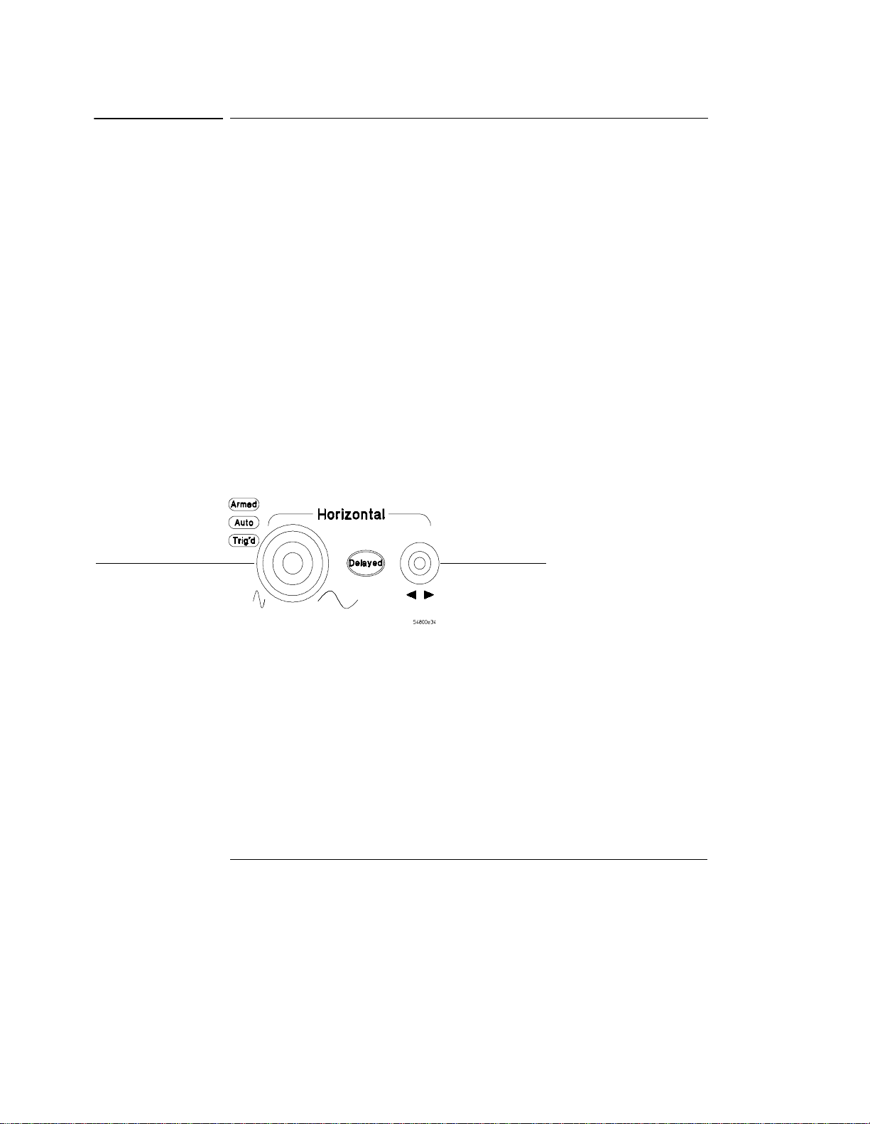
To adjust sweep speed and horizontal position
To adjust sweep speed and horizontal position
• To stretch the waveform horizontally, turn the sweep speed knob
clockwise. To shrink it horizontally, turn the knob counter-clockwise.
The sweep speed knob is the larger of the two horizontal control knobs. It is
marked with a set of sine wave symbols. Stretching the waveform means there
are fewer seconds displayed per division. Shrinking the waveform means there
are more seconds displayed per division.
• To move the waveform to the right, turn the horizontal position knob
clockwise. To move the waveform to the left, turn the horizontal
position knob counter-clockwise.
Moving the waveform to the right shows more of the pre-trigger data (data
acquired before the trigger event). Moving the waveform to the left shows more
of the post-trigger data (data acquired after the trigger event).
The horizontal position knob is the smaller of the two horizontal control knobs.
It is marked with a set of arrows. There is a detent programmed into the
software so there is a momentary pause at zero while you are turning the knob.
Continuing to turn the knob will move the horizontal position through zero.
Figure 3-7
Sweep speed
knob—use this to
adjust the sweep
speed
Horizontal position
knob—use this to
adjust the
horizontal position
Horizontal Sweep Speed and Position Controls
3-13
Page 54

Figure 3-8
Using the Oscilloscope
To magnify a part of the waveform using delayed sweep
To magnify a part of the waveform using delayed sweep
• To turn on the delayed sweep, press Delayed. To turn it off, press
Delayed again.
The waveform display area splits into two regions. The top one is the main
sweep. The bottom is the delayed sweep, which represents a software
expansion of the acquired waveform data. A section of the waveform in the
main sweep window is highlighted to indicate the part shown in the delayed
sweep window.
The horizontal sweep speed and horizontal position controls now change how
the waveform is shown in the delayed sweep window. The sweep speed will
change the amount of magnification, while the position will change the part of
the waveform in the main sweep window that is shown in the delayed sweep
window.
Press this key to magnify
a part of the waveform in
a new window on the
display
Magnifying Part of the Waveform with Delayed Sweep
3-14
Page 55
Using the Oscilloscope
To set the oscilloscope to trigger on an edge
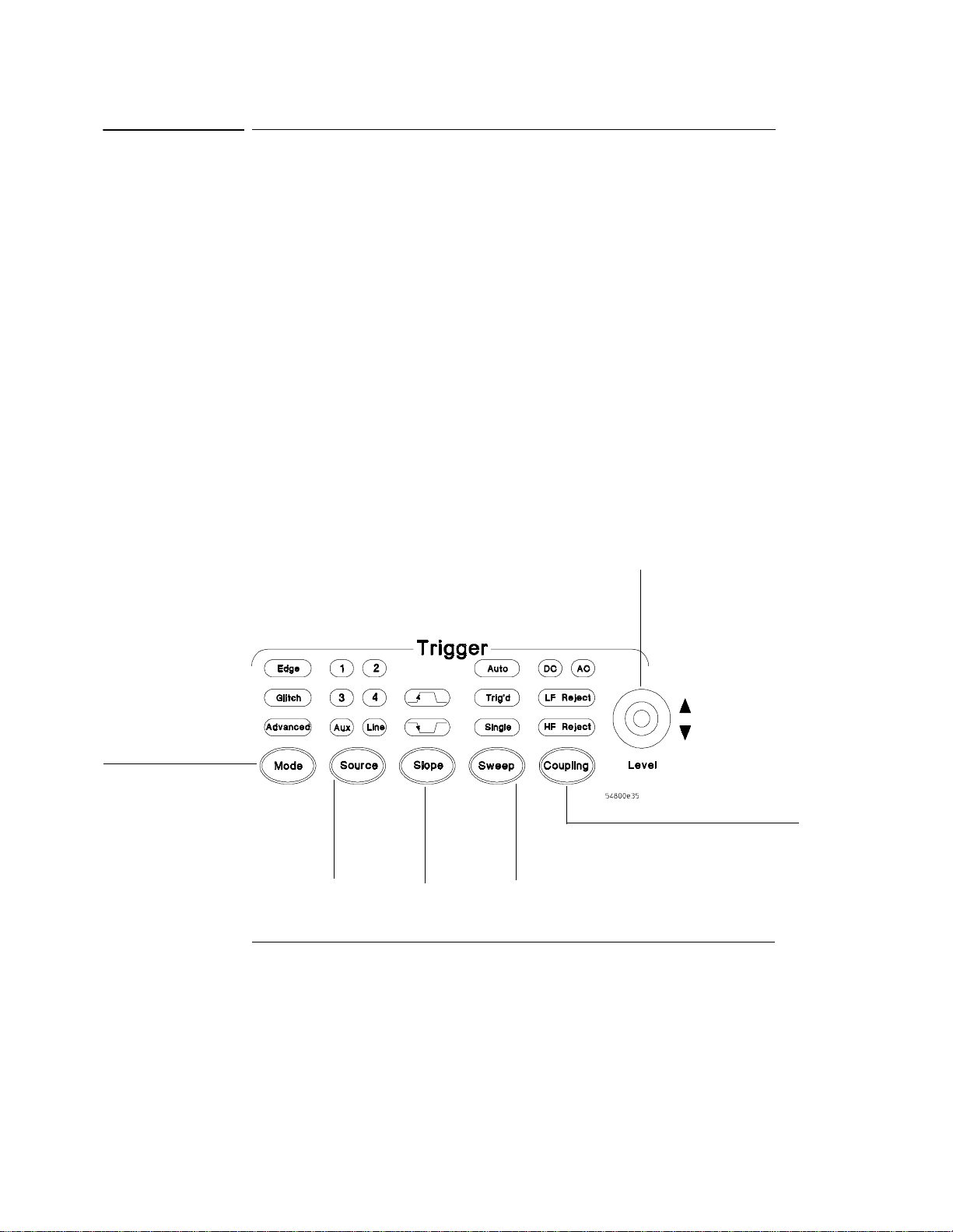
To set the oscilloscope to trigger on an edge
1 Press and release the Mode key until the Edge LED indicator is
illuminated.
2 Press and release the Source key until the desired source LED is
illuminated.
You can choose any of the channels or the Aux Trig In (4-channel ocilloscopes)
or Ext Trigger as the source for an edge trigger.
3 Press the Slope key until the desired slope LED is illuminated.
You can have an edge trigger on a rising or falling edge.
4 Press the Sweep key until the Trig’d LED is illuminated.
The oscilloscope will wait for the edge before initiating a sweep.
5 Select an input coupling for the trigger signal by pressing the Coupling
key.
You can choose DC, AC, LF Reject, or HF Reject. See the built-in Information
System for more information on when to use each type of coupling.
6 Turn the Level knob to adjust the voltage level at which the oscilloscope
will trigger.
Figure 3-9
Select Edge
mode
Trigger Controls and Indicators
Select the
trigger
source
Select rising
or falling
edge for the
trigger
Select Trig’d
Single, or Auto
Set trigger level
Set coupling
characteristics
for the trigger
3-15
Page 56

Using the Oscilloscope
To use the markers
To use the markers
Markers make it easier to make precise measurements because the marker
measurement readouts show exact voltage and time positions for the markers.
The measurements are based on actual waveform data from the acquisition
system, not on approximations based on the display position, so you can be sure
that the values are highly accurate.
• To turn on Marker A, press the Marker A key.
Marker A has a solid line pattern on the waveform display. It is associated with
the first available source on the display. Press the key again to move to the next
available source. When there are no more sources, the marker turns off.
• To turn on Marker B, press the Marker B key.
Marker B has a dashed line pattern on the waveform display. It is associated
with the first available source on the display. Press the key again to move to
the next available source. When there are no more sources, the marker turns off.
• To move a marker on the waveform, press and hold the left arrow or
right arrow key next to the desired Marker key. Release the key when
the marker is at the desired waveform event.
The marker snaps to and follows the shape of the waveform on the screen. The
voltage value shown for a marker is the value of the waveform at the specified
horizontal time, which is set with the marker arrow keys. This is the default
mode. You can change the marker mode using the graphical interface. See the
built-in information system for details.
Figure 3-10
Marker Keys
3-16
Toggle Marker A
on and off
Toggle Marker B
on and off
Move each marker
with respect to the
Page 57

Using the Oscilloscope
To use the quick measurements
To use the quick measurements
• To turn on the quick measurement display, press the QuickMeas key.
The four preset measurements defined in the Quick Measurement configuration
are enabled and results are displayed on the screen for the first waveform
source. The default measurements are: V
• To measure parameters for another waveform, press the QuickMeas
key until that waveform is the one shown in the measurement readout.
Continuing to press the QuickMeas key cycles through each of the waveforms
available.
• To turn off the quick measurement display, press and release the
QuickMeas key until the measurements are turned off.
The measurement results disappear from the screen.
See the built-in information system (described in Chapter 4) for information on
how to configure the Quick Measurement capability, using the Customize
Measurement feature of the graphical interface.
, Period, Frequency, and Rise Time.
pp
Figure 3-11
Quick Measurement Key
Press this key to turn
Quick Measurements
on or off
3-17
Page 58

Using the Oscilloscope
To reinitialize the oscilloscope
To reinitialize the oscilloscope
When you need to restore the oscilloscope to a known configuration, use the
Default Setup key. If you press the Default Setup key and the oscilloscope does
not seem to be functioning properly, try cycling power. If the oscilloscope still
does not seem to function properly, use the following key-down powerup
procedure.
1 Turn off the power to the oscilloscope.
2 Turn on the power to the oscilloscope.
3 Hold down any one of the arrow keys next to the Marker A and Marker B
keys.
4 When the oscilloscope display appears, release the key you held down
in step 3.
A key-down powerup completely reinitializes the oscilloscope, including the
configuration RAM. It does not affect saved waveforms or setups, which are
stored on the hard disk drive.
Figure 3-12
Key-Down Powerup
Press and hold
any one of
these keys...
...press the power switch, then release the key
when the oscilloscope display appears.
3-18
Page 59
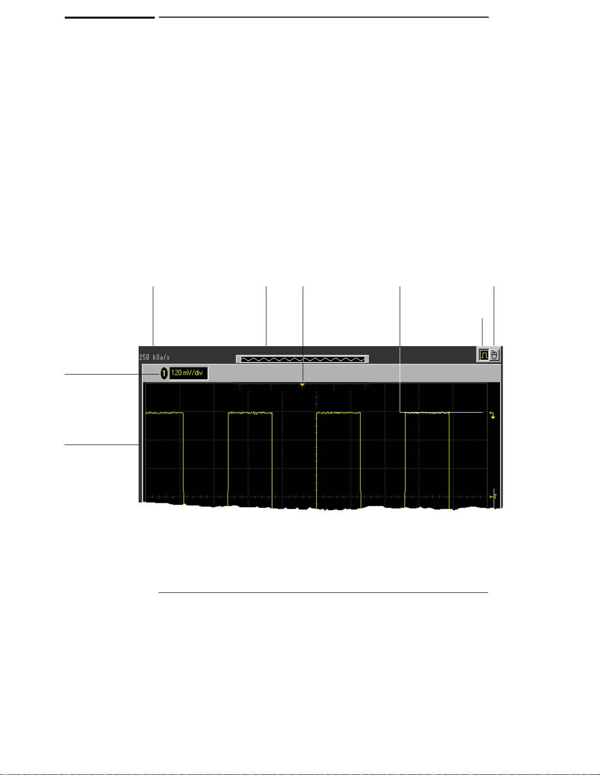
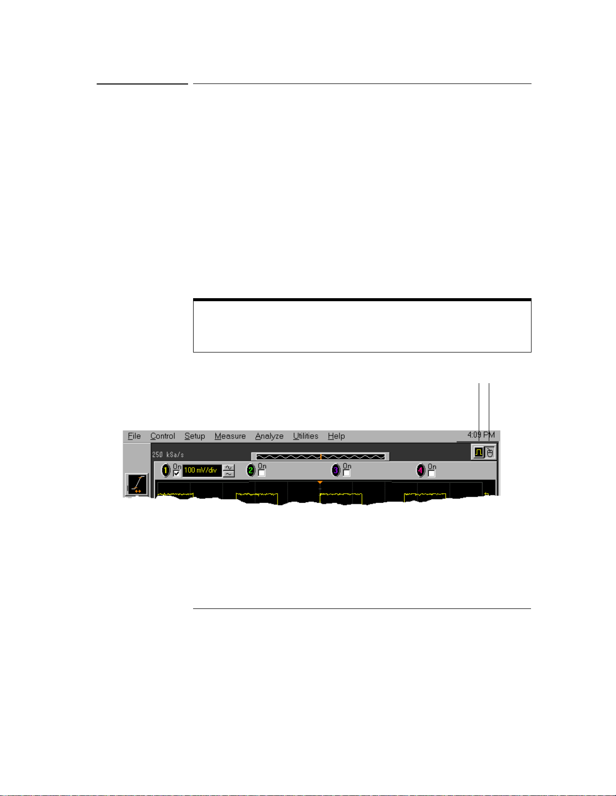
Figure 3-13
Current
sampling
rate
Using the Graphical Interface
With the graphical interface for the Infiniium Oscilloscope, you can
access all the configuration and measurement features of the
oscilloscope through an easy-to-use system of menus, tool bars, dialog
boxes, icons, and buttons.
Full-Screen Mode
Full-screen mode maximizes the waveform viewing area and removes
the graphical interface menus and toolbars so you can concentrate on
your measurement. In full-screen mode, the display looks like the
following two figures.
Memory bar—highlighted
area shows how much of
acquisition memory is
displayed on the screen
Trigger
point
indicator
Ground
reference
indicator for
this channel
This button enables
the graphical interface
This button enables
full-screen mode
Vertical status
bar—only
channels that are
on are shown, in
matching colors
Waveform
display area
Infiniium Oscilloscope Top of Display in Full-Screen Mode
3-19
Page 60

Figure 3-14
Horizontal and
trigger status bar
Using the Oscilloscope
Run/stop mode
(run shown in
green, stop in
red)
Sweep
speed
Trigger level
reference
indicator
Horizontal
position
(delay)
Trigger
level
Horizontal
reference
indicators
(left, center, right)
—horiz ontal
delay is time at
the highlighted
arrow
Infiniium Oscilloscope Bottom of Display in Full-Screen Mode
3-20
Page 61

Figure 3-15
Menu bar
Measurement
toolbar
(can be turned
off)
Graphical Interface Mode
Click the graphical interface enable button to switch to the graphical
interface. When the graphical interface is enabled, the display looks like
the following two figures. See “To switch between the graphical interface
and full-screen mode” on page 3-30.
Access the
Channel Setup
dialog box
Turn this
channel
on or off
Set vertical
scaling
Memory bar—
highlighted area shows
how much of
acquisition memory is
displayed on the screen
Using the Oscilloscope
This button enables
the graphical
interface
Click here to set the
time and date
Infiniium Oscilloscope Top of Display in Graphical Interface Mode
3-21
Page 62
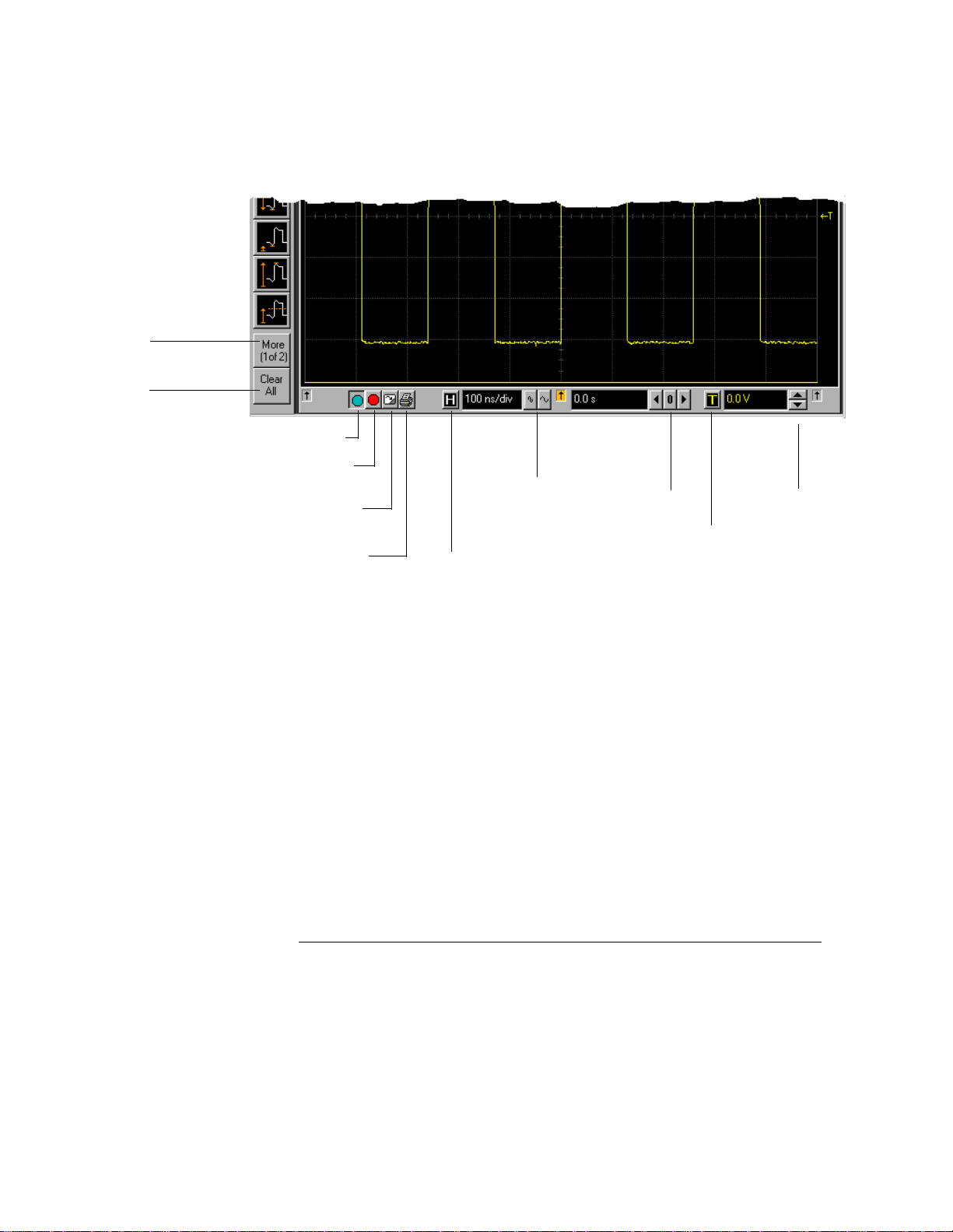
Figure 3-16
See more
measurements
Turn off any
measurements
that are running
(use Clear display
to reset/restart
measurements)
Using the Oscilloscope
Run
Stop
Clear
display
Print
screen
Set
sweep
speed
Access the
Horizontal Setup
dialog box
Set
horizontal
position
(delay)
Access
the
Trigger
Setup
dialog
box
Set
trigger
level
Infiniium Oscilloscope Bottom of Display in Graphical Interface Mode
To make it easy to see which controls affect each waveform, the
oscilloscope uses color consistently throughout the graphical interface.
These colors match the ones used on the front-panel knobs. For
example, the color of the waveform for channel 1 matches the color of
the knobs for that channel. If channel 1 is the trigger signal, all of the
trigger configuration items, including the trigger level reference icon (at
the right side of the waveform display area), will match that color. The
buttons associated with that channel, vertical scaling and offset settings,
ground reference indicator, and measurements done on that channel
also have the same color.
3-22
Page 63

Using the Oscilloscope
You can still use the front panel when the graphical interface is enabled.
All changes made to the front-panel settings are reflected in the
graphical interface, and changes made using the graphical interface are
reflected in the front panel where applicable. Use whichever interface
is easiest for you in a particular measurement situation. For example, it
might be easiest to set a coarse vertical scale using the knobs, then finetune the setting using the graphical interface.
The graphical interface is arranged so the most common functions that
affect the waveform display are located around the edge of the waveform
display area. These include the measurement toolbar, horizontal and
trigger toolbar, and vertical toolbar.
Measurement Toolbar
The measurement toolbar contains icons representing the most
commonly used automatic measurements built into the oscilloscope.
Drag and Drop Measurements By dragging one of the measurement
icons to a waveform in the waveform display area, you can make that
measurement on the waveform. As you drag a measurement icon around
the screen, the icon outline changes color to match the color of the
closest waveform. This makes it easy to see which waveform will be
measured when you drop the icon. For those measurements that are
done on waveform features, the measurement is made at the feature
closest to the location where you dropped the icon. For example, you
might want to measure the rise time of the fifth rising edge; dropping
the rise time measurement icon at that edge will cause the measurement
to be made on that edge.
You can also make a measurement by simply clicking the icon on the
measurement toolbar, then selecting the source to be measured in the
dialog box that appears. When you start a measurement this way, any
measurements on waveform-specific features will measure the first
appropriate feature on the waveform. For example, a rise time
measurement will measure the first rising edge on the waveform.
Each waveform can have multiple simultaneous measurements and the
measurements can all be of the same type, if desired. For example, you
can have 3 pulse width measurements on different parts of the same
waveform.
3-23
Page 64

Using the Oscilloscope
Geometric Measurement Indicators
For each measurement currently
running, a geometric indicator at the measurement location on the
waveform corresponds to an identical indicator in the measurement
results readout. This makes it easy for you to verify that the readout
shows results for the correct waveform and the correct feature on that
waveform. See figure 3-38 for an example.
Tool Tips To find out what a particular measurement tool does, hold
the mouse pointer over it for a moment. A small popup will appear that
describes the measurement.
Other Measurement Features There are more measurements available
than will fit on a single toolbar. Click the More (1 of 2) or More (2 of 2)
icons to see other measurements. Clicking Clear Meas will remove all
selected measurements from the waveform display area.
You can turn off the measurement toolbar to remove it from the screen
and enlarge the waveform viewing area. Use the Customize Display
Layout command on the Measure menu.
3-24
Page 65

Figure 3-17
Using the Oscilloscope
Tab Display Area
The tab display area located beneath the waveform viewing area appears
when a measurement is on, mask testing is enable, a histogram is
enabled, markers are on, or color graded persistence is on.
Tab Display Area
The display area shows information and statistics for the particular tab
that is selected. The type of markers that are shown in the waveform
viewing area depend on the tab that you have selected. The selected
tab has an orange border to reflect the type of markers being displayed.
For example, when the Histogram tab is selected, the markers are
histogram markers and are used to define the histogram window.
Waveform Display Area
The waveform display area shows the waveforms, and optionally, the
results of your measurements. Several display options, including a grid,
are available and can be configured using the graphical interface.
3-25
Page 66
Using the Oscilloscope
Waveform Manipulation
When the graphical interface is enabled, two
features are available that can simplify your work with waveforms:
• Direct Manipulation—you can use the mouse to click and drag
waveforms to new vertical positions, which changes the vertical offset,
or to new horizontal positions, which changes the horizontal position
or delay value.
• Zoom—you can click and drag a rectangular area on the display, then
click inside it to zoom on that section of the waveforms. The
oscilloscope does this in one of two ways. If acquisition is stopped,
the magnification is done by the oscilloscope software. If acquisition
is running, the oscilloscope automatically adjusts the vertical scaling
and offset and the horizontal sweep speed and position to present the
zoomed section of the waveforms.
See “To zoom on a section of the waveform” on page 3-49.
Avoid Overdriving Vertical Input Amplifiers
When zooming on a waveform with the oscilloscope running, be careful to keep the
signal within the screen vertically to avoid overdriving the vertical input amplifiers.
This causes waveform distortion and erroneous measurement results.
Ground Reference Indicators A small symbol is shown at the right side
of the waveform display area for each waveform that is on, including
channels, waveform memories, and functions. This symbol represents
the ground reference point for each channel; it moves when you change
the vertical offset. You can also drag this symbol up and down using the
mouse; doing so automatically changes the vertical offset for that
waveform.
Menu Control and Menus
The graphical interface control button, in the upper right-hand corner
of the display, enables the graphical interface of the oscilloscope. When
the graphical interface is enabled, the display looks like figure 3-15 and
figure 3-16, including a menu bar, measurement toolbar (if enabled), and
graphical controls for vertical, horizontal, trigger, and acquisition. You
can switch to full-screen mode to maximize the waveform viewing area
and eliminate the menu bar, measurement toolbar, and other graphical
controls.
3-26
Page 67

Using the Oscilloscope
To reinitialize the oscilloscope
You can use the menu bar for most oscilloscope configuration functions.
Context-sensitive menus, which pop up to provide a selection of
commands within particular regions of the user inteface, are available in
the following regions:
• Memory bar
• Waveform display area
• Measurement toolbar
• Horizontal and acquisition controls
You display a context-sensitive menu by clicking the right mouse button
with the pointer in one of these regions. For more information on
context-sensitive menus, see “To select a command from a contextsensitive menu” on page 3-34.
Vertical Settings and Controls
The top of the waveform display area includes the vertical settings and
controls. In full-screen mode, only channels that are turned on are
shown, with the corresponding vertical scaling settings in volts per
division. When the graphical interface is enabled, all channels are shown.
Each has a checkbox allowing you to turn that channel on or off, and a
set of controls allowing you to change the vertical scaling. Clicking
directly on the vertical scaling value displays a pop-up numeric keypad
allowing you to set a precise vertical scale.
Horizontal and Trigger Toolbar
At the bottom of the waveform display area is the horizontal and trigger
toolbar. This includes the run/stop controls, the horizontal controls, and
the trigger controls.
Run/Stop Controls See figure 3-25. At the left side of the bar are three
icons:
• The leftmost is a blue-green octagon. Clicking on this starts an
acquisition. (Same as pressing the Run key on the front panel.)
• The middle is a red octagon. Clicking on this stops acquisition. (Same
as pressing the Stop key on the front panel.)
• The rightmost is a small windshield wiper. Clicking on this clears
acquired waveform data from the display. (Same as pressing the Clear
Display key on the front panel.)
3-27
Page 68

Using the Oscilloscope
To reinitialize the oscilloscope
Horizontal settings and controls
The middle of the bar contains the
horizontal settings and controls. Leftmost is a button, labeled with an
“H.” Clicking on this will display the horizontal setup dialog box.
Next is the current sweep speed. Clicking on this displays a pop-up
numeric keypad so you can set a particular sweep speed. Or, you can
click on the two icons to the right of the sweep speed setting to cycle
through the preset speeds. The leftmost icon shrinks the waveform,
which decreases the sweep speed and increases the time per division.
The rightmost icon stretches the waveform, which increases the sweep
speed and decreases the time per division.
Next is the horizontal position (delay) setting. Clicking on this displays
a pop-up numeric keypad that allows you to set a particular position. Or,
you can use the three icons to the right. The left arrow moves the
waveform to the left, the center “0” resets the delay to zero, and the right
arrow moves the waveform to the right.
Across the toolbar are three vertical arrows. These are the left, center,
and right horizontal reference indicators. Clicking on one of these arrows
moves the horizontal position to the respective horizontal reference
position on the display—left, center, or right. Assuming the horizontal
position is at zero:
• Left means the information on the display is all post trigger.
• Center means the information to the left of center is pre trigger; to
the right is post trigger.
• Right means the information on the display is pre trigger.
The horizontal position value represents the time relative to the trigger
at the respective horizontal reference. When you change the horizontal
sweep speed, the waveforms expand and contract about this reference
position.
Trigger settings and controls The right side of the bar contains the
trigger settings and controls. These will vary depending on the current
trigger configuration, which can be set using the front panel and the
graphical interface. Advanced trigger configuration items are available
only through the graphical interface. You can click on the button labeled
with a “T” to bring up the trigger setup dialog box.
When the scope is set for edge trigger on a particular channel, the trigger
level setting is shown. You can click on it to display a pop-up numeric
3-28
Page 69

Using the Oscilloscope
To reinitialize the oscilloscope
keypad that allows you to set a particular trigger level. You can also click
on the up and down arrows to the right of the setting to increase or
decrease the trigger level, respectively. Or, you can click on the trigger
reference indicator at the right side of the display and drag it up or down
to change the trigger level.
3-29
Page 70
Using the Oscilloscope
To switch between the graphical interface and full-screen mode
To switch between the graphical interface and fullscreen mode
• To enable graphical interface mode, click on the outlined square wave
button in the upper right-hand corner of the display.
The button changes state, and the menus and measurement toolbar appear.
The graphical interface menus let you access all the functions in the
oscilloscope, including features that are not available from the front-panel
controls. You can also use the oscilloscope’s built-in information system.
• To enable full-screen mode, click the larger square wave button in the
upper right-hand corner of the display.
The button changes state, and the menus and measurement toolbar disappear.
Choosing this option allows you to focus only on the waveform and
measurement. You must make changes to the oscilloscope configuration using
the front panel.
Use Knobs and Keys to Configure the Oscilloscope in Full-Screen Mode
In full-screen mode, the range of mouse pointer motion is limited to the area of the
button for enabling the interface. You must use the front-panel knobs and keys to
configure the oscilloscope.
Figure 3-18
Interface Mode Control Buttons
3-30
Click th is button
to enable fullscreen mode
Click this button
to enable
graphical
interface mode
Page 71

Using the Oscilloscope
To perform basic user interface operations
To perform basic user interface operations
• To move the mouse pointer on the screen, move the mouse on the
mouse pad.
If you run out of room on the mouse pad surface, pick up the mouse and set it
down on the mouse pad where you will have room for motion.
•To click on an item in the graphical interface, point at that item with the
mouse pointer, then press and release the left mouse button.
•To right-click on an item in the graphical interface, point at that item
with the mouse pointer, then press and release the right mouse button.
You use the right-click operation to access context-sensitive menus. See “To
select a command from a context-sensitive menu” on page 3-34.
• To use a radio button, click to select the desired item.
Radio buttons appear in many different dialog boxes in the oscilloscope
graphical interface. See the Persistence radio buttons in figure 3-19. You can
choose only one option at a time.
• To use a check box, click the mouse button with the pointer in the box.
A check mark in the box indicates that item is selected. See the Connect Dots
check box in figure 3-19. To clear the selection, click the mouse button with
the pointer in the box.
• To use a drop-down list box, click the arrow at the right-hand side of
the box. Then click on the desired choice to highlight it.
See the Language selection list box in figure 3-20.
• To use a spin box, click the up arrow to increase the value displayed in
the box, and the down arrow to decrease it.
See the Intensity spin box in figure 3-19.
• To move a dialog box, press and hold the left mouse button with the
pointer in the title bar, drag the box to a new position on the screen,
then release the mouse button.
• To close a dialog box, click the “X” symbol in the upper right-hand
corner of the box, or click the Close button in the box.
3-31
Page 72

Figure 3-19
Click to put a check mark
check box
in the
enable Connect Dots
mode
Click one of these
radio buttons
select Minimum,
Variable, or Infinite
persistence
and
to
Using the Oscilloscope
To perform basic user interface operations
Click and drag the
title bar
to m ov e th e
dialog box on the
screen
Dialog Box Interface Elements
Click one of these
Close buttons
close the dialog box
to
Click on the upward
arrow in this
to increase the
intensity of the grid
Click on the
downward arrow to
decrease the
intensity of the grid
spin box
Figure 3-20
Click the arrow in a
drop-down list box
Dialog Box with a Drop-Down List Box
3-32
...
...to see the options you can
choose
Page 73

Figure 3-21
Using the Oscilloscope
To select a command from the menu bar
To select a command from the menu bar
1 Click on a menu bar item.
2 Move the pointer to the desired menu item.
3 Click the mouse button.
The desired command is executed, or a dialog box is presented for you to
configure the oscilloscope.
If you continue to hold the mouse button after step 1, release the button in
step 3 to execute the command.
Some menus have submenus. These are indicated by an arrow at the right side
of the command. When you move the pointer to one of these menu commands,
the submenu automatically appears. You can then move the pointer to the
desired command on that submenu and click the mouse button to execute the
command.
Selecting a Command from the Menu Bar
Click the Measure menu,
then Customize, and then
Measurement
Definitions to customize
the measurement setup
3-33
Page 74
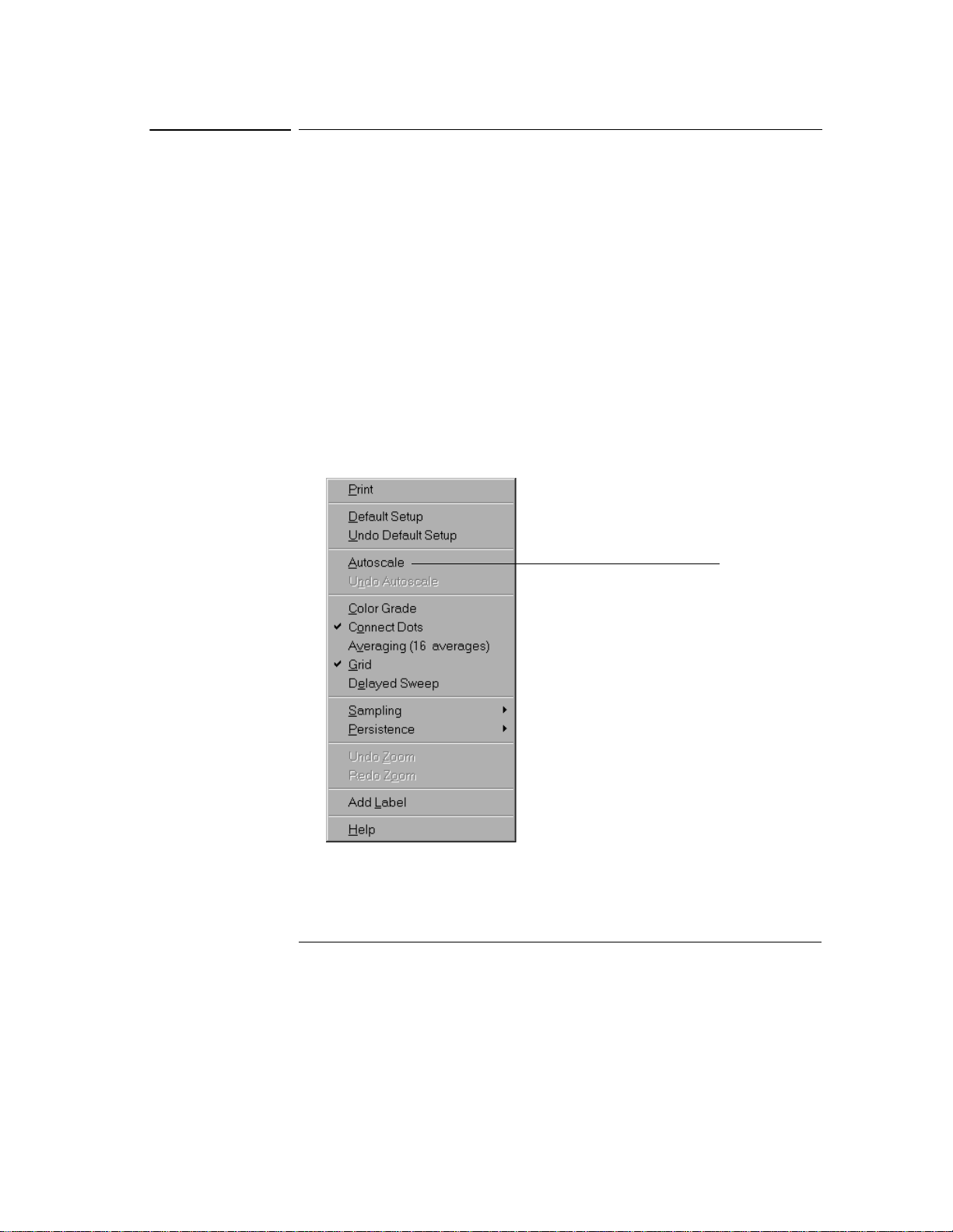
Figure 3-22
Using the Oscilloscope
To select a command from a context-sensitive menu
To select a command from a context-sensitive menu
1 Move the mouse pointer to a particular area of the display in which you
want to change the oscilloscope configuration.
Context-sensitive menus provide quick access to commands and configuration
items that relate only to the context of the particular graphical interface item
in which they are found. They are available in the following display areas:
memory bar, measurement toolbar, waveform display area, and horizontal
settings and controls.
2 Click the right mouse button.
3 Move the pointer to the desired menu item.
4 Click the mouse button.
If you continue to hold the mouse button after step 2, release the button in
step 4 to execute the command.
Right-click the mouse in the
waveform display area, then
select Autoscale from the menu
to force the oscilloscope to
autoscale the current
waveform(s)
Selecting a Command from a Context-Sensitive Menu
3-34
Page 75
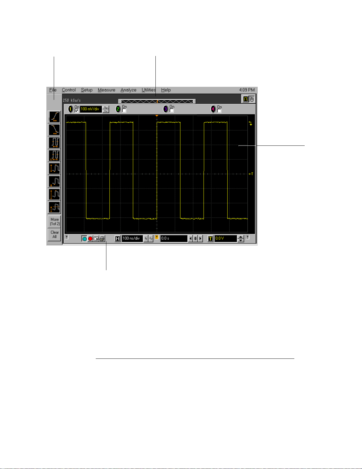
Figure 3-23
Right-clic k in this region
to see the Measurement
Setup context-sensitive
menu
Using the Oscilloscope
To select a command from a context-sensitive menu
Right-click in this region
to see the Acquisition
Setup context-sensitive
menu
Right-click in the
waveform display
area to see the
waveform contextsensitive menu
Right-click in this region to see
the horizontal, trigger, and run
controls context-sensitive menu
Location of Context-Sensitive Menus
3-35
Page 76

Figure 3-24
Using the Oscilloscope
To change the mouse settings
To change the mouse settings
1 Select Utilities, then Preferences, then select Mouse.
You will see the dialog in figure 3-24.
• To swap the functions of the mouse buttons, click the Swap Buttons check
box until a check mark appears.
• To change the time for a double-click, use the spin box controls.
2 Click Close.
If you are left-handed, or simply find it more comfortable to use the mouse or
other pointing device on the left side of the oscilloscope, swapping the functions
of the mouse buttons can make the mouse easier to use. Changing the doubleclick time primarily affects double-clicks in the Open and Save Waveform and
Open and Save Setup dialog boxes. See the built-in information system
(described in chapter 4) for details.
Check this box to swap
the mouse buttons for
left-handed operation
Adjust the double-click
speed using this spin box
Changing the Mouse Settings
3-36
Page 77
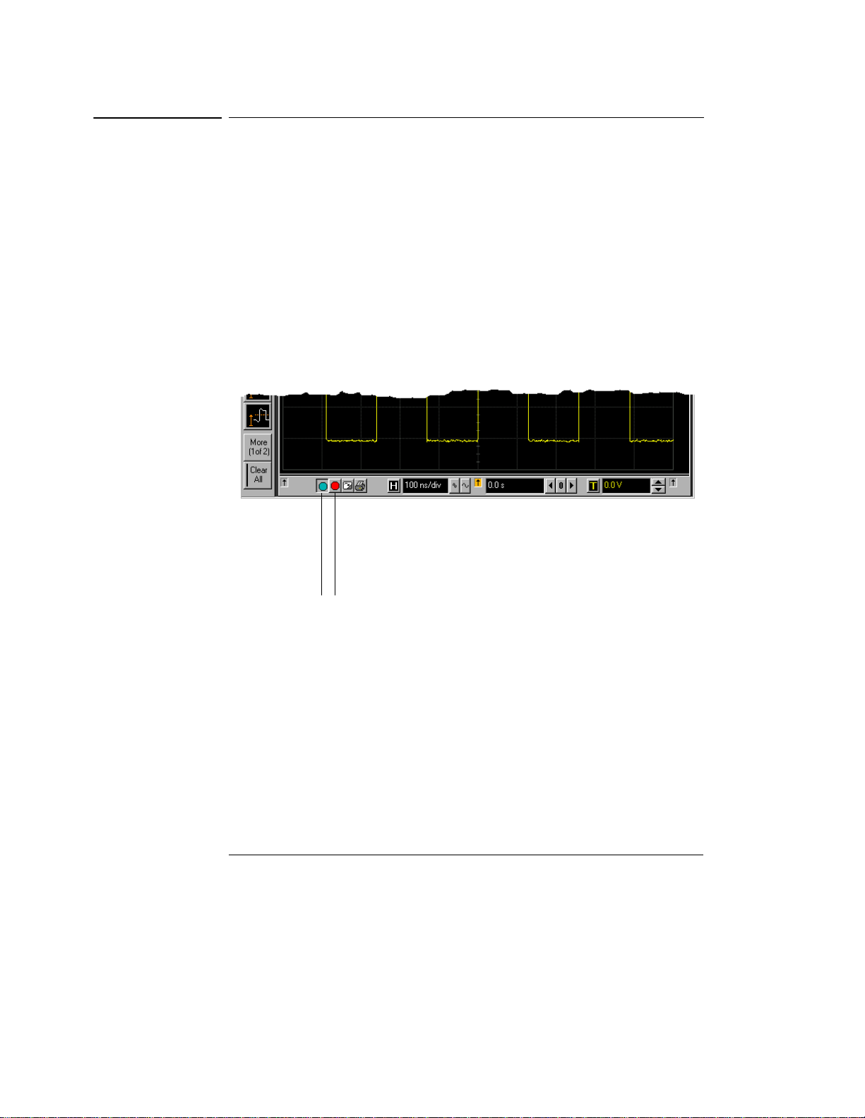
Figure 3-25
Using the Oscilloscope
To start and stop waveform acquisition
To start and stop waveform acquisition
• To start waveform acquisition, click the start button at the bottom of
the waveform display area.
• To stop waveform acquisition, click the stop button at the bottom of
the waveform display area.
See figure 3-25.
You can still use the Run and Stop keys on the front panel while the graphical
interface is enabled. However, if you are performing many graphical interface
operations, it is easier to start and stop the oscilloscope using the buttons in the
interface, so you do not have to remove your hand from the mouse.
Click this button
to st art wave form
acquisition
Start and Stop Icons
Click this button
to stop waveform
acquisition
3-37
Page 78

Figure 3-26
Using the Oscilloscope
To clear the waveform display
To clear the waveform display
• Click the clear display button at the bottom of the waveform display.
See figure 3-26.
You can still use the Clear Display key on the front panel while the graphical
interface is enabled.
Clearing the display removes all displayed waveform data in preparation for
another acquisition. It also resets all automatic measurements and
measurement statistics.
Clearing the Display
3-38
Click this button to
clear the wa vefor m
displa y
Page 79

Figure 3-27
Using the Oscilloscope
To print the screen
To print the screen
• Click the print button at the bottom of the waveform display.
See figure 3-27.
Infiniium prints the screen to the default printer according to the configuration
that you have selected in the Printer Setup dialog box.
Click this button to
print the screen
Printing the Screen
3-39
Page 80

Figure 3-28
Using the Oscilloscope
To turn a channel on or off
To turn a channel on or off
• To turn a channel on, click the check box next to the channel number
so that a check mark appears in the box. To turn a channel off, click
the check box again to clear it.
See figure 3-28.
If you are not using a channel, you can turn it off. This simplifies the waveform
display and also increases the display update rate. When you turn off a channel,
the current vertical scaling factor and vertical scale buttons for that channel
disappear. They re-appear when you turn the channel on.
You can also turn a channel on or off by using the Channel Setup dialog box, or
by using the front panel key for that channel.
Turn a channel on by
clicking in the On
check box until a
check mark appears
Turn a channel off
by clicking in the
On check box until
the box is cleared
Turning a Channel On or Off
3-40
Page 81

Using the Oscilloscope
To adjust the vertical offset
To adjust the vertical offset
• Click and hold the left mouse button on the waveform you want to
move, then drag the mouse up or down to move the waveform to the
desired offset. Release the mouse button when finished.
or
• Click and hold the left mouse button on the ground reference indicator
for the waveform you want to move, then drag the mouse to move the
waveform to the desired offset. Release the mouse button when
finished.
or
• Click the channel button in the vertical toolbar, then set the vertical
offset using the spin box control in the Channel Setup dialog box.
If you leave the mouse pointer on the waveform (without clicking the mouse),
the pointer changes into crossed arrows as a visual indicator that you can drag
the waveform when you click and hold the mouse button. If you move the mouse
up or down, the interface constrains the movement vertically and adjusts
vertical offset only. If you initially move the mouse left or right, the interface
constrains the movement horizontally and changes the horizontal position
setting only.
You can also adjust the vertical offset through the Channel Setup dialog box.
See “To access the channel setup” on page 3-44.
3-41
Page 82

Figure 3-29
Using the Oscilloscope
To adjust the vertical offset
Click to access the
Channel Setup dialog,
then set vertical offset
using the spin box or
numeric keypad...
...or click on the
ground
reference
indicator and
drag it up or
down to change
Adjusting Vertical Offset
...or click on the
waveform and
drag it up or down
to do the same
thing.
3-42
Page 83

Figure 3-30
Using the Oscilloscope
To adjust vertical scaling
To adjust vertical scaling
• To make the waveform bigger, click on the larger waveform button next
to the channel number near the top of the display. To make the
waveform smaller, click on the smaller waveform button.
See figure 3-30. The number of volts per division decreases.
The number of volts per division increases. The current setting in volts per
division is shown next to the waveform buttons for the channel. Notice that the
setting is color-coded to match the waveform color for easy recognition.
You can also adjust the vertical scaling by clicking on the current setting, which
is shown next to the waveform buttons for the channel. This displays a pop-up
numeric keypad that allows you to set an exact value for the scaling. Or, you
can adjust the vertical scaling through the Channel Setup dialog box. See “To
access the channel setup” on page 3-44.
Click to display a pop-up
numeri c keypad that le ts you
specify a particular vertical
scaling value
Click to make the
waveform bigger
(fewer volts per
division)
Adjusting Vertical Scaling
Click to make the
waveform smaller
(more volts per
division)
3-43
Page 84

Figure 3-31
Using the Oscilloscope
To access the channel setup
To access the channel setup
• Click the channel number button at the top of the waveform display.
or
• Select the desired channel from the Setup menu.
With the channel setup dialog, you can set the vertical scaling, offset, input
coupling, and input impedance. It also lets you specify the characteristics of
the probe, using the Probes button. You can set attenuation ratio, attenuation
units, and measurement units for the probe, or perform a probe calibration. For
Agilent Technologies probes that are compatible with the AutoProbe Interface,
the oscilloscope will automatically set these characteristics (except for skew)
after identifying the probe when it is connected to the channel input.
Click one of the
channel buttons at
the top of the
waveform display...
Accessing the Channel Setup
3-44
...or select a
channel from
the Setup
menu...
...to access the channel
setup dialog box.
Page 85

Figure 3-32
Using the Oscilloscope
To set the horizontal reference point
To set the horizontal reference point
• Click on one of the arrows at the bottom of the waveform display.
The selected horizontal reference is highlighted.
The vertical arrows at the bottom of the display correspond to the left, center,
and right horizontal reference points. This is the position of the trigger if the
horizontal position is set to zero delay. A non-zero horizontal position value is
the time relative to the trigger event at the selected horizontal reference point.
Click to set the
horizontal reference
to the left side of the
display
Horizontal Reference Points
Click to set the
horizontal reference
to the center of the
display
Click to set the
horizontal reference
to the right side of the
display
3-45
Page 86

Figure 3-33
Using the Oscilloscope
To adjust sweep speed
To adjust sweep speed
• To stretch the waveform horizontally, click the larger waveform button
next to the horizontal sweep speed setting at the bottom of the
waveform display. To shrink the waveform horizontally, click the
smaller waveform button.
See figure 3-33. The oscilloscope decreases or increases the number of seconds
per division based on your selection.
You can also adjust the sweep speed by clicking on the current setting. This
displays a pop-up numeric keypad that allows you to set an exact value for the
sweep speed. Or, you can adjust the sweep speed through the Horizontal Setup
dialog box. See “To access the horizontal setup” on page 3-48.
Click here to
display the
horizontal
setup dialog
box
Click here to set
the sweep
speed directly
through a popup numeric
keypad
Adjusting Sweep Speed
3-46
Click t o shrink
the waveform
(more
seconds per
division)
Click to stretch the
waveform (fewer
seconds per
division)
Page 87

Figure 3-34
Using the Oscilloscope
To adjust horizontal position
To adjust horizontal position
The horizontal position is the time relative to the trigger at the highlighted
horizontal reference point.
• To zero the horizontal position, click the 0 button next to the position
value at the bottom of the waveform display.
This will position the trigger event at the highlighted horizontal reference point.
• To move the waveform to the right or left, click the right or left arrow
next to the position value at the bottom of the waveform display. Or,
click and hold the mouse button on the desired waveform and drag the
waveform to the right or left. Release the mouse button when the
waveform is in the desired position.
When you click and drag a waveform, this changes the horizontal position for
all channels and functions on the display, but not that of waveform memories.
You can also adjust the horizontal position through the horizontal setup dialog.
Adjusting Horizontal Position
Click to set the
horizontal position
through a pop-up
numeric keypad
Move the
waveform
to the left
Reset the
horizontal
position to
zero
Move the
wave form to
the right
3-47
Page 88

Figure 3-35
Using the Oscilloscope
To access the horizontal setup
To access the horizontal setup
• Click the horizontal setup button at the bottom of the waveform display.
or
• Select Horizontal from the Setup menu.
See figure 3-35.
Using the Horizontal Setup menu, you can set sweep speed, position, and the
horizontal reference. You can also set up the delayed time base window, which
uses software expansion to present a magnified view of an area of the waveform.
See the built-in information system (described in chapter 4) for details.
Click this
button...
...or select this
menu item...
Accessing the Horizontal Setup
...to access the horizontal
setup dialog box.
3-48
Page 89

Using the Oscilloscope
To zoom on a section of the waveform
To zoom on a section of the waveform
1 Click and hold the left mouse button in a blank space within the
waveform display area, then drag the mouse to draw a rectangle around
the areas of interest on the waveform(s). Release the mouse button.
2 Click the mouse once anywhere inside the rectangle drawn in step 1.
How the zoom takes place depends on whether acquisition is running or
stopped. If running, the oscilloscope adjusts vertical scale, vertical offset, sweep
speed, and horizontal position as necessary to best rescale the area you defined
in step 1. If stopped, the oscilloscope does a software magnification of the
waveform.
In either case, a small dialog box appears in the corner of the screen, with a
single “Undo” button; by clicking this button, you will undo the zoom and return
the oscilloscope to its previous settings.
Avoid Overdriving the Vertical Input Amplifiers
When the oscilloscope is running, the input waveform can overdrive the vertical
input amplifiers if you expand the vertical excessively. The result is distortion of
the waveform. Ensure that you select a region that will keep all of the waveform
on the screen vertically.
3-49
Page 90

Figure 3-36
Using the Oscilloscope
To zoom on a section of the waveform
Click and hold the
mouse button, drag
to create a selection
rectangle, then click
inside the rectangle
to zoom the display
on the waveforms
inside the rectangle
Zooming on a Section of the Waveform
3-50
Page 91
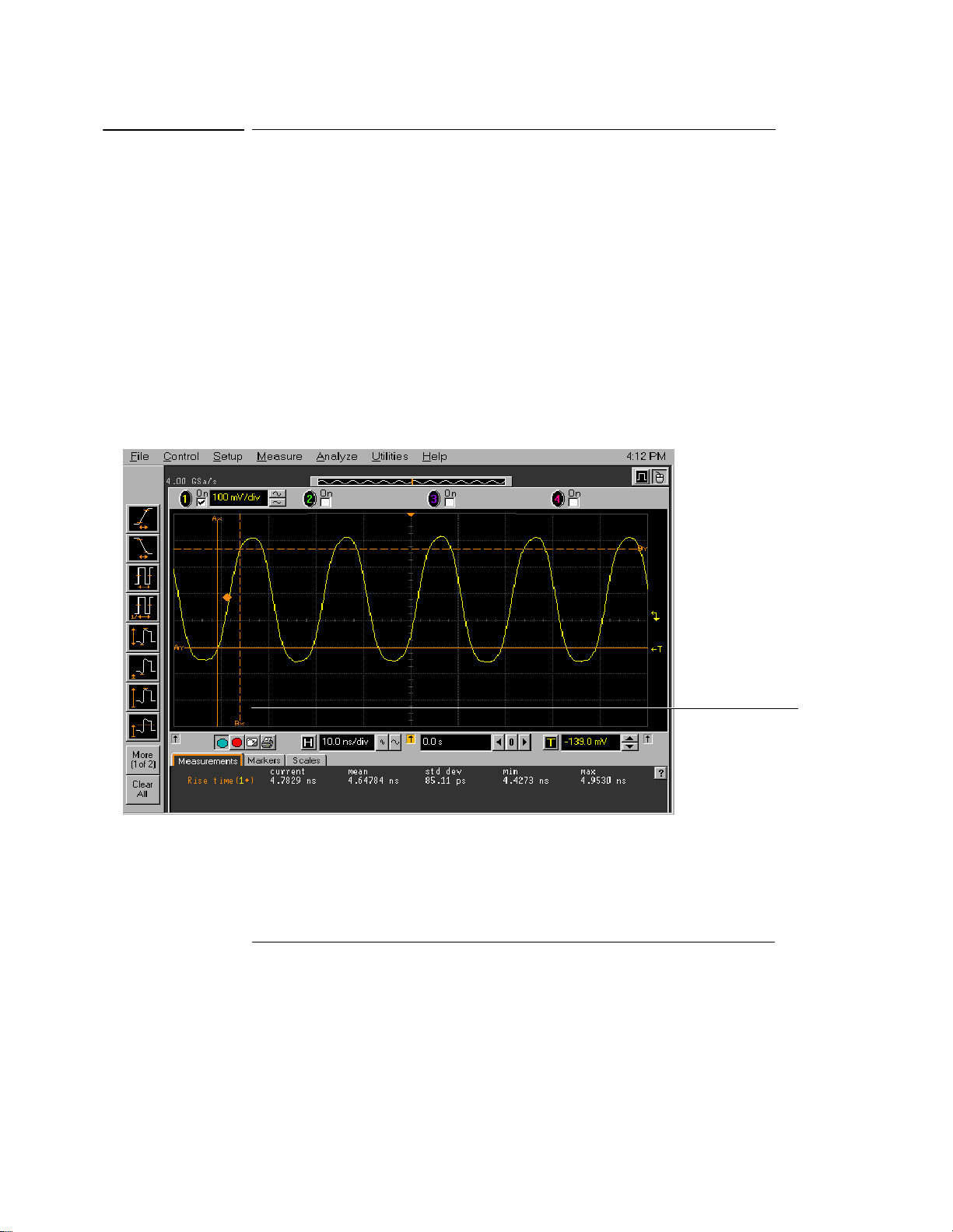
Figure 3-37
Using the Oscilloscope
To move the markers using the graphical interface
To move the markers using the graphical interface
1 Turn on the markers.
You can use the Marker A and Marker B keys on the front panel, or select Markers
from the Measure menu.
2 Click and hold the left mouse button while the mouse pointer is on one
of the markers, then drag the marker to the position you want on the
waveform. Release the mouse button.
Clicking and dragging a marker makes it easy to quickly move the marker to the
desired waveform event. You can use the front-panel arrow keys for fine
adjustment. Or, you can select the Markers command from the Measure menu
and set the marker position precisely. See the built-in information system for
details.
Moving the Markers
To move a marker,
click the mouse with
the pointer on the
marker, drag the
marker to the new
position, then
release the mouse
button
3-51
Page 92

Using the Oscilloscope
To make a measurement on a waveform
To make a measurement on a waveform
• Click and hold the mouse button on a measurement icon, then drag the
icon to the waveform event you want to measure. Release the mouse
button.
or
• Click on a measurement icon, then specify which source you want to
measure in the dialog box that is displayed.
For measurements on waveform features, such as those that involve waveform
edges, if you click the measurement icon and specify a source, the measurement
defaults to using the first feature it encounters, starting at the left side of the
display. When you make the measurement using drag-and-drop, the
measurement uses the waveform feature closest to the point where you drop
the icon.
The Measurement toolbar is normally displayed at the left side of the screen
when the graphical interface is enabled. You can turn off the toolbar, thereby
increasing the waveform display area, by selecting Measure, then Customize,
then Display Layout.
Only the most commonly used measurements are available on the toolbar.
Others are available by selecting them from the Measure menu. A few
specialized measurements are available only through the GPIB programming
command set to the oscilloscope. See the Programmer’s Reference.
When you drag and drop a measurement icon on a waveform, notice that the
icon outline changes color to match the color of each waveform it touches. This
enables you to easily see which waveform will be measured when you release
the mouse button. Also, the measurement results are also displayed in color to
make it easy to see which waveform source is being measured.
For edge-sensitive measurements, when you drop the measurement icon on a
waveform, a geometric icon appears in the waveform marker color. This icon
shows exactly where the measurement is being made. The icon is also displayed
next to the measurement results readout to associate the readout with the
waveform and feature being measured. See figure 3-38. This feature helps you
distinguish measurement results from each other when you make multiple
measurements on the same waveform, but at different waveform features. For
example, a series of rise time measurements on several different edges of the
same waveform all have unique geometric icons to show each measurement’s
location.
The markers default to tracking the last measurement started. The marker
position readout defaults to off to reduce clutter, but can be turned on in the
Measure menu if desired.
3-52
Page 93

Figure 3-38
Channel
numbers
associate the
measurement
results with
the channel
waveform
Using the Oscilloscope
To make a measurement on a waveform
Waveform Measurements
In some cases,
geomet ric icons
are also
displayed to
associate the
3-53
Page 94

Figure 3-39
Using the Oscilloscope
To access the trigger setup
To access the trigger setup
• Click the trigger setup button at the bottom of the waveform display.
or
• Select Trigger from the Setup menu.
The trigger setup dialog allows you to select any of the different modes of
triggering supported by the oscilloscope—Edge, Glitch, or Advanced, with
choices under Advanced of Pattern, State, Delay by Time, Delay by Events,
Violation, or Video. You can set the parameters and conditions for each of those
trigger modes.
Click this button...
...or select this menu
item...
Accessing the Trigger Setup
...to access the trigger setup dialog.
3-54
Page 95

Figure 3-40
Select Edge mode
Using the Oscilloscope
To set an edge trigger
To set an edge trigger
1 Click on the trigger setup button at the bottom of the waveform display.
This brings up the trigger configuration dialog. See “To access the trigger
setup.”
2 Click on Edge.
3 Click on the source you want to use for the trigger signal.
4 Click to select either the rising or falling edge of the trigger source.
5 Set the trigger level using the spin box.
You can also click on the trigger level setting to display a pop-up numeric
keypad, where you can enter the trigger level directly.
Select Triggered
sweep (or Single for
single-shot
acquisition)
Select the trigger
source
Select rising or
falling edge
Set the trigger level
using the spin box
controls
Setting an Edge Trigger
3-55
Page 96

Using the Oscilloscope
To enable 8.0 GSa/s sampling mode on the 54845A
To enable 8.0 GSa/s sampling mode on the 54845A
1 Select Acquisition from the Setup menu.
2 Click the radio button labeled “8 GSa/s, 64k pts (Channels 1, 3)” under
Configuration in the Acquisition Setup dialog box.
3 Click Close.
The 54845A achieves the maximum 8.0 GSa/s sampling rate by combining
acquisition hardware from two channels on a single channel. Thus, in this mode,
only channels 1 and 3 are available for input. Because the memory from two
channels is combined, the acquisition memory depth is doubled. This can be
useful in some measurement situations, even when you do not need the
maximum sampling rate of 8.0 GSa/s.
All sampling rates up to and including 8.0 GSa/s are available in this mode. You
can select the actual sampling rate used by selecting Manual under Sampling
Rate in this dialog box. You can also set the actual memory depth by selecting
Manual under Memory Depth in this dialog box.
Return to four-channel operation by clicking the radio button labeled “4 GSa/s,
32k pts (Channels 1, 2, 3, 4).” The maximum sampling rate is then 4.0 GSa/s.
Figure 3-41
Enables 8 GSa/s
sampling (two
channels are
available for input)
Enables 4 GSa/s
sampling (four
channels are
available for input)
Acquisition Setup for 8.0 GSa/s Sampling on the 54845A
3-56
Page 97

Using the Oscilloscope
To enable 4.0 GSa/s sampling mode on the 54835A
To enable 4.0 GSa/s sampling mode on the 54835A
1 Select Acquisition from the Setup menu.
2 Click the radio button labeled “4 GSa/s, 64k pts (Channels 1, 3)” under
Configuration in the Acquisition Setup dialog box.
3 Click Close.
The 54835A achieves the maximum 4.0 GSa/s sampling rate by combining
acquisition hardware from two channels on a single channel. Thus, in this mode,
only channels 1 and 3 are available for input. Because the memory from two
channels is combined, the acquisition memory depth is doubled. This can be
useful in some measurement situations, even when you do not need the
maximum sampling rate of 4.0 GSa/s.
All sampling rates up to and including 4.0 GSa/s are available in this mode. You
can select the actual sampling rate used by selecting Manual under Sampling
Rate in this dialog box. You can also set the actual memory depth by selecting
Manual under Memory Depth in this dialog box.
Return to four-channel operation by clicking the radio button labeled “2 GSa/s,
32k pts (Channels 1, 2, 3, 4).” The maximum sampling rate is then 2.0 GSa/s.
Figure 3-42
Enables 4 GSa/s
sampling (two
channels are
available for input)
Enables 2 GSa/s
sampling (four
channels are
available for input)
Acquisition Setup for 4.0 GSa/s Sampling on the 54835A
3-57
Page 98

Using the Oscilloscope
To set dialog box preferences
To set dialog box preferences
• To change the background for the dialog boxes used by the
oscilloscope, select Utilities, then User Preferences. Then select
Opaque, Translucent, or Transparent in the User Preferences dialog
box.
The oscilloscope displays a dialog box when it needs information from you to
set up a particular aspect of an operation or measurement. You can choose
opaque, translucent, or transparent backgrounds for the dialog boxes. Opaque
and translucent settings are easier for most users to read and interact with
because the dialog box is clearly defined against the oscilloscope display.
Translucent and transparent settings make it easier to see the waveform while
you are changing the oscilloscope configuration; this allows you to see the
results of your changes immediately without closing the dialog box.
Windows and Dialog Boxes are Opaque
Windows and dialog boxes for file operations, error messages, and the built-in
information system are always opaque.
• To allow multiple dialog boxes on the screen at a time, select Utilities,
then User Preferences. Then select Allow Multiple Active Dialogs in
the User Preferences dialog box.
Normally, the oscilloscope displays only one dialog box at a time, and you must
close that dialog box before opening another. With Allow Multiple Active
Dialogs, you can change several different aspects of the oscilloscope
configuration simultaneously. This option is usually easier to use if you select
Translucent or Transparent dialogs, because it will be easier to see the effects
of your changes.
Remove Clutter from the Waveform Display
Having too many dialog boxes on the screen can make it difficult to see the
waveform. Close dialog boxes you are not using to remove clutter from the
waveform display.
3-58
Page 99

Figure 3-43
Using the Oscilloscope
To set dialog box preferences
Select one of these
commands to change how
dialog boxes look on the
screen
Select this command to
allow many dialog boxes to
be present on the screen at
one time
Setting Dialog Box Options
3-59
Page 100
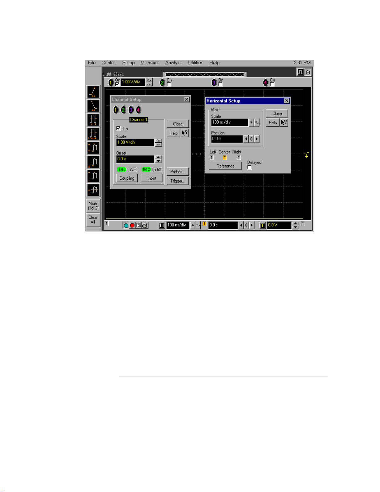
Figure 3-44
Using the Oscilloscope
To set dialog box preferences
Multiple Active Dialogs (Opaque)
3-60
 Loading...