

Page 1

H
HP Infinium Demo Upgrade Kit
Upgrade Instructions
Since the introduction of the HP Infinium Oscilloscope family in
September 1997, HP has incorporated several improvements in the
oscilloscopes. These improvements are included in this upgrade.
This upgrade kit (P/N 54810-68710) provides hardware and software you
need to upgrade your HP Infinium Demo Unit or Loaner Unit to a more
durable HP Infinium Oscilloscope. All of the improvements in this
upgrade are automatically built into all HP Infinium scopes
manufactured starting April 1998.
Hewlett-Packard understands that oscilloscopes that are used as sales
demonstration units and loaner units are subjected to mechanical stress
that is higher than normal. This means that the HP demonstration units
and loaner units require these upgrades without a doubt, based on their
high usage and high visibility.
HP Infinium scopes manufactured before March 1998 did not include
the Local Area Network (LAN) capability as a standard feature. If you
have an HP demonstration unit or loaner unit that does not have a LAN
card installed, you should use this opportunity to add the LAN capability.
The HP E2650A LAN Upgrade Kit contains the hardware, software, and
installation instructions for adding the LAN capability to all HP Infinium
Oscilloscopes. See Service Note 54810A-04 for additional information.
Models Affected
These are the HP Infinium Oscilloscope models that may require this
upgrade:
• HP 54810A
• HP 54815A
• HP 54820A
• HP 54825A
• HP 54845A
Page 2

Upgrade Instructions
This upgrade is required if the oscilloscope serial number prefix is lower
than 3813. For example:
Serial # US 3473nnnn — An upgrade is required.
Serial # US 3813nnnn — An upgrade is not required.
Tools Required
• T-15 Torque Wrench (>30 in-lb)
• HP Infinium Service Manual (See Upgrade Note 1 in
“Notes in Upgrade Procedures” at the end of this document.)
Use HP Service Manual 54810-99003 for these oscilloscope models:
• HP 54810A
• HP 54815A
• HP 54820A
• HP 54825A
Use HP Service Manual 54845-99002 for these oscilloscope models:
• HP 54845A
Follow ESD Precautions
When performing the procedures in this upgrade, you must use proper
ESD precautions. As a minimum, you must place the instrument on a
properly grounded ESD mat and wear a properly grounded ESD wrist
strap.
CAUTION Failure to implement proper antistatic measures may result in damage to the
HP Infinium Oscilloscope.
CAUTION Do not remove or replace any circuit board assemblies in the oscilloscope
while power is applied. The assemblies contain components that may be
damaged if you remove or replace the assembly while power is connected to
the oscilloscope.
2
Page 3

Upgrade Instructions
WARNING SHOCK HAZARD! To avoid electrical shock, adhere closely to the following
procedures. Also, after disconnecting the power cable, wait at least three
minutes for the capacitors on the power supply and sweep boards to discharge
before servicing the oscilloscope. Hazardous voltages exist on the inverter for
the display monitor.
Parts Required
The parts listed here are contained in this Demo Upgrade Kit, and are
necessary in upgrading the scope. The LAN Upgrade Kit part number
is also shown.
Contents of HP Infinium Demo Upgrade Kit (P/N 54810-68710)
Quantity Part Number Description
1 54810-66503
or
54810-66523 w/cable
3 0515-1038 Stand-off screws
3 0380-1407 Stand-off
3 1401-0202 Insulators
1 5090-4370 Upgrade label
2 5021-4302 Handle screws (black)
1 54810-42201 Front panel cover
1 54810-68708 Software pouch
1 1400-0249 Cable tie
1 54810-92002 Upgrade Instructions
Scope Interface Board
(See Upgrade Note 4.)
Optional Part (Order separately if LAN is to be added.)
Quantity Part Number Description
1 E2650-68701 LAN Upgrade Kit (See Upgrade Note 2.)
3
Page 4

Upgrade Instructions
Tasks You Will Perform
In the upgrade procedures that follow, you will perform these tasks:
Step 1. Run Self-Tests
Step 2. Determine the Software Version Number
Step 3. Install Software (if necessary)
Step 4. Prepare HP Infinium for Hardware Changes
Step 5. Install the LAN Card (if necessary)
Step 6. Exchange the Scope Interface Card
Step 7. Secure All Internal Connections
Step 8. Finish HP Infinium Hardware Changes
Step 9. Install the Mouse and Keyboard
Step 10. Run the LAN Setup Procedure (if necessary)
Step 11. Run Self-Tests Again
Step 12. Attach the Upgrade Label
Step 13. Return the Old Scope Interface Card to HP
Notes that you’ll see in the upgrade procedures are described in
“Notes in Upgrade Procedures” at the end of this document.
4
Page 5

Upgrade Instructions
Step 1. Run Self-Tests
Step 1. Run Self-Tests
1 Enable the graphical interface.
With the mouse pointer on
the right hand button, click
the mouse to enable the
graphical interface.
2 Select Self Test from the Utilities menu.
3 Select Scope Self Test from the Self Test drop down list box.
4 Click the Start Test button and follow the instructions that appear
on the screen.
5 Verify that all of the tests pass.
If the self-tests fail, you must correct the problem(s) before continuing. If
necessary, refer to the appropriate HP Service Manual for more information.
Step 2. Determine the Software Version Number
1 Enable the graphical interface.
2 Select About Infinium... from the Help menu.
3 Make a note of the software version number.
Step 3. Install Software (if necessary)
1 If you determined the Infinium software version number to be less than
A.02.00, you must install the software supplied in the Demo Upgrade
Kit, P/N 54810-68710.
2 Refer to the installation instructions printed on Disk 1, and install all of
the software supplied.
5
Page 6

Upgrade Instructions
Step 4. Prepare HP Infinium for Hardware Changes
Step 4. Prepare HP Infinium for Hardware Changes
1 Install the front panel cover onto the Infinium Oscilloscope. This will
allow you to place the instrument face down so that you can easily
remove and replace the cabinet sleeve.
2 Remove the oscilloscope’s side handle, the rear screws, and feet using
a Torx-15 driver. Then remove the oscilloscope’s cabinet sleeve
(MP52).
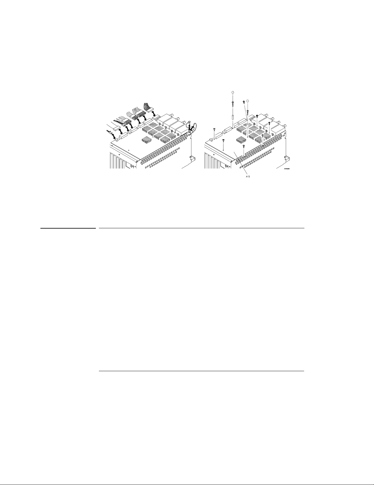
3 Remove the screws from the acquisition assembly as shown, and
connect the stand-offs using stand-off screws.
a. For HP 54845A:
On the bottom side of the scope, locate the acquisition board assembly
(A13). Remove the two mounting screws directly in front of and
behind the Channel 1 A/D heatsink. Then remove the mounting screw
directly in front of the Channel 3 A/D heatsink.
6
Page 7
Upgrade Instructions
Step 5. Install the LAN Card (if necessary)
b. For all other HP Infinium Models:
On the bottom side of the scope, locate the acquisition board assembly
(A13). Remove the mounting screw directly behind the Channel 1 A/
D heatsink. Then remove the mounting screw directly behind the
Channel 3 A/D heatsink.
4 Install the 25-mm spacers using the 35-mm screws in place of the screws
you removed in the previous step.
5 Install the protector caps on top of the spacers to prevent intermittent
electrical contact with the bottom of the cabinet sleeve.
Step 5. Install the LAN Card (if necessary)
1 Determine whether you need to install the LAN card. See Upgrade
Note 3.
2 If you will be installing the LAN card, follow the instructions in the
HP E2650A Ethernet Adapter Installation Guide supplied in the LAN
Upgrade Kit.
3 If you will not be installing the LAN card, go to the next step.
7
Page 8

Upgrade Instructions
Step 6. Exchange the Scope Interface Card
Step 6. Exchange the Scope Interface Card
1 Refer to the appropriate HP Service Manual for your oscilloscope
model. See the section “To remove and replace the scope interface card
and SVGA display card” for information you may need.
2 Remove the old Scope Interface card — P/N 54810-66502.
3 Install the new Scope Interface card — P/N 54810-66503 or
P/N 54810-66523 with cable.
Step 7. Secure All Internal Connections
1 Verify that all cards are seated properly in their respective motherboard
sockets.
2 Verify that all cable connectors are seated properly and that their locks
are fully engaged. Pay close attention to both connectors of:
• W8 — display-to-floppy disk drive cable
• W11 — acquisition signal cable
• W12 — probe power and control cable
• W13 — probe interface cable
3 Secure the front panel keyboard cable (W16) to the scope interface card
(A6) with the cable tie that is provided.
4 Replace any cable that could become disconnected during rough
shipping and handling.
8
Page 9

Upgrade Instructions
Step 8. Finish HP Infinium Hardware Changes
Step 8. Finish HP Infinium Hardware Changes
1 Re-install the oscilloscope’s cabinet sleeve, sleeve screws, and rear feet.
Tighten all screws to the HP specification of 2.4 Nm (21 in-lbs) of torque.
2 Inspect the side-handle screws. The old screws are silver-colored.
Replace the old screws with the new black-oxide colored looseningresistant screws.
3 If the screws are of the old type, remove them using a pair of long-nose
pliers or the Torx-15 driver.
4 Using either the shaft of the pliers or the Torx driver, pry off the handle
end caps. Then place the handle assembly on a flat surface with the
screws pointing upward. Place the pliers or Torx driver between the
end caps and the handle plastic, and pry off the end caps.
5 Re-assemble the handle using the new black handle screws. Make sure
that when the two-dimple side of the handle faces up, the screws are
mounted into the bushing with the screw threads pointed down. Press
the end caps firmly back onto the handle assembly.
6 Re-attach the black-screw-equipped side handle, and tighten both
handle screws to the HP specification of 2.4 Nm (21 in-lbs) of torque.
9
Page 10
Upgrade Instructions
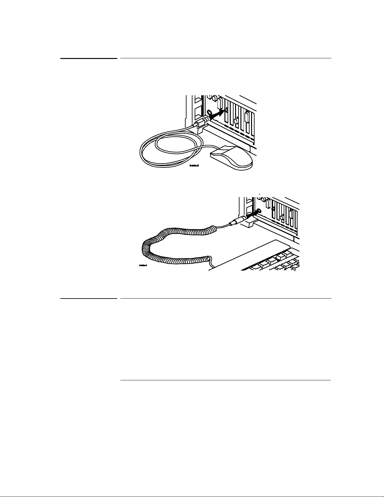
Step 9. Install the Mouse and Keyboard
Step 9. Install the Mouse and Keyboard
1 Connect the mouse as shown.
2 Connect the keyboard as shown.
Step 10. Run the LAN Setup Procedure
1 Refer to the HP E2650A Ethernet Adapter Installation Guide supplied
in the LAN Upgrade Kit and locate the LAN setup procedure.
2 Follow instructions to run the LAN setup procedure. See Upgrade
Note 3.
10
Page 11
Upgrade Instructions
Step 11. Run Self-Tests Again
Step 11. Run Self-Tests Again
1 Enable the graphical interface.
2 Select Self Test from the Utilities menu.
3 Select Scope Self Test from the Self Test drop down list box.
4 Click the Start Test button and follow the instructions that appear
on the screen.
5 Verify that all of the tests pass.
If the self-tests fail, you must correct the problem(s) before continuing. If
necessary, refer to the appropriate HP Service Manual for more information.
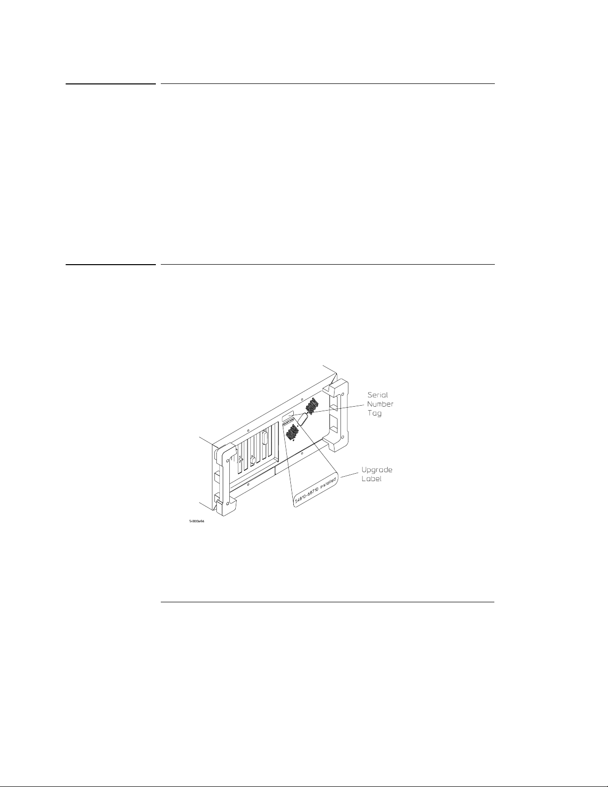
Step 12. Attach the Upgrade Label
1 Write "54810-68710 Installed" on the label.
2 Locate the space below the serial number on the scope rear panel.
3 Attach the supplied upgrade label to this space.
4 Return the Infinium with the front panel cover installed.
11
Page 12

Upgrade Instructions
Step 13. Return the Old Scope Interface Card to HP
Step 13. Return the Old Scope Interface Card to HP
1 Return the old scope interface card (P/N 54810-66502) to HP Electronic
Measurements Division.
The old Scope Interface Card will be upgraded to 54810-66503.
Don’t Delay in Returning the Old Scope Interface Card
It is important that you return the old Scope Interface Cards directly to the
HP factory in a timely manner. The remaining instructions tell you how.
2 Package the card(s) properly to prevent ESD and mechanical damage.
3 Express ship the old Scope Interface card(s) to:
Hewlett-Packard Company
Factory Repair Center
1900 Garden of the Gods Road
Colorado Springs, CO 80907
Attention: Mark Rowley
4 Bill HP Electronic Measurement Division for all parts required, and for
2 hours of labor.
What to do Next
The HP Infinium Demo upgrade is complete. This upgrade has added the key
improvements which increase the reliability of this family of oscilloscopes. This
upgrade will enable this Infinium to better withstand the high stress of the
demonstration and loaner activity.
12
Page 13

Upgrade Instructions
Notes in Upgrade Procedures
Notes in Upgrade Procedures
These notes are referenced in the upgrade procedures in this document.
Upgrade Notes Description
Note 1 Copies of HP Infinium manuals are available over the world wide web at
http://www.hp.com/info/infinium_support.
Note 2 Include the cost of the LAN upgrade kit in the billing to HP Electronic
Note 3 Adding LAN capability to an HP Demonstration Unit or HP Loaner Unit is
Note 4 The 54810-66523 will replace the 54810-66503 in Summer 1998. This
Measurements Division (HP EMD).
not included as part of this HP Infinium Demo Upgrade Kit. For information
about installing a LAN card, see the HP E2650A Ethernet Adapter
Installation Guide (E2650-92001).
Many HP Demonstration and HP Loaner units have already been upgraded
with LAN capability. For units that have not been upgraded, HP EMD will
accept the cost of adding LAN capability during this upgrade.
assembly will add a more durable connector.
13
Page 14

*54810-92002*
*54810-92002*
HP Part Number 54810-92002
Printed June 1998
14
 Loading...