


Agilent Technologies
5000 and 6000 Series Oscilloscope
Probes and Accessories
Selection Guide Data Sheet
Table of Contents
Probe Compatibility Table . . . . . . . . . . . 2
Passive Probes . . . . . . . . . . . . . . . . . . . . . 3
High-voltage Passive Probes . . . . . . . . 4
Active Differential Probes . . . . . . . . . . . 5
Active Single-ended Probes . . . . . . . . . 8
Mixed Signal Oscilloscope
Logic Probes . . . . . . . . . . . . . . . . . . . . . . 10
Current Probes . . . . . . . . . . . . . . . . . . . . 12
Wedge Probe Adapters . . . . . . . . . . . . 14
PC Connectivity . . . . . . . . . . . . . . . . . . . 15
Agilent IntuiLink Software . . . . . . . . . . . 15
Miscellaneous Accessories . . . . . . . . 16
Testmobile . . . . . . . . . . . . . . . . . . . . . . . . . 16
Carrying Cases . . . . . . . . . . . . . . . . . . . . . 16
Rackmount Kit . . . . . . . . . . . . . . . . . . . . . . 16
Sales and Service . . . . . . . . . . . . . . . . . 17
To get the most out of your scope, you need the right
probes and accessories for your particular application. That’s why Agilent Technologies offers a complete family of innovative probes and accessories for
the 5000 and 6000 Series scopes. For the most up-todate and complete information about Agilent’s accessories, please visit our web site at
www.agilent.com/find/scope_probes

2
Probe Compatibility Table
For ordering information when
replacing your probe or probe
accessory: Refer directly to the
page number listed in the table of
contents for your probe model.
To assist you in selecting
the proper probe for your
application: Use our probe
compatibility table below to find
DSO5000A DSO5000A MSO/DSO6000A
[5]
MSO/DSO6000A
[4]
Probe Type Probe Model 100 MHz 300 - 500 MHz 100 MHz 300 MHz - 1 GHz
Passive Probes N2863A 10:1 300 MHz Recommended Compatible Compatible Compatible
Page 3 (included in 5000 Series 100/300 MHz)
10070C 1:1 20 MHz Recommended Recommended Recommended Recommended
10073C 10:1 500 MHz Compatible Recommended Compatible Recommended
(included in 6000 Series 300 MHz 1 GHz and 5000 Series 500 MHz)
10074C 10:1 150 MHz Recommended Compatible Recommended Compatible
(included in 6000 Series 100 MHz)
High-voltage Passive Probes 10076A 4 kV Recommended Recommended Recommended Recommended
Page 4
N2771A 30 kV Recommended Recommended Recommended Recommended
Active Differential Probes 1130A 1.5 GHz
[1]
Incompatible Recommended Incompatible Recommended
Page 5
N2772A 20 MHz (use with N2773A) Recommended Recommended Recommended Recommended
1141A 200 MHz (use with 1142A) Compatible Recommended Compatible Recommended
Active Single-ended Probes 1156A 1.5 GHz
[2]
Compatible Recommended Incompatible Recommended
Page 8
1144A 800 MHz (use with 1142A) Incompatible Recommended Incompatible Recommended
1145A 750 MHz 2-ch (use with 1142A) Incompatible Recommended Incompatible Recommended
Mixed Signal Oscilloscope 10085-68701 2x8-channel Recommended Recommended Recommended Recommended
Logic Probes
[3]
Page 10 54620-68701 16-channel Incompatible Incompatible Recommended Recommended
(included in MSO6000A)
Current Probes 1146A 100 kHz Recommended Recommended Recommended Recommended
Page 11
N2780A 2 MHz (use with N2779A) Recommended Recommended Recommended Recommended
N2781A 10 MHz (use with N2779A) Recommended Recommended Recommended Recommended
N2782A 50 MHz (use with N2779A) Recommended Recommended Recommended Recommended
N2783A 100 MHz (use with N2779A) Recommended Recommended Recommended Recommended
1147A 50 MHz Recommended Recommended Incompatible Recommended
[1] The 1130A probe amplifier supports both single- and differential-ended measurements. Higher bandwidth InfiniiMax probe model 1131A, 1132A, and 1134A are also
supported by 5000 and 6000 Series 300 MHz - 1 GHz models.
[2] The 1157A and 1158A are also supported by all 5000 and 6000 Series 300 MHz - 1 GHz models.
[3] Recommended for MSO6000A MSOs only.
[4] These Infiniium active probes are not supported by 5000 and 6000 Series – 1152A, 1153A, 1154A, 1155A, 1159A, 1168A, and 1169A.
[5] MSO/DSO6000A 100 MHz models do not support any Agilent Infiniium active single-ended or differential probes.
the probes that are recommended
for use with your 5000 and 6000
Series oscilloscope.

3
• Designed for optimal performance
with your Agilent 5000 and 6000
Series scope
• 1:1 and 10:1 attenuation
• 20 MHz to 500 MHz
Rugged, high-quality probes
at a reasonable price
Agilent 10070-family passive
probes are a great choice if you’re
looking for high quality at a very
reasonable price. These generalpurpose probes are designed
specifically to give you optimal
performance with your 5000
and 6000 Series oscilloscopes.
Ruggedized for general-purpose
measurements, they feature a
durable cable and a solid stainless
steel probe body encased with a
hard, fracture-resistant plastic.
They’re designed and tested to
ensure the probes operate in
the toughest of conditions The
N2863A low-cost passive probe
provides a 10:1 attenuation and
features a high input resistance
of 10 MΩ.
Probes come with the following
accessories:
• General-purpose retractable
hook tip hooks onto wires and
test points for hands-free
probing
• Ground bayonet provides
short, flexible ground lead for
high-frequency measurements
• General-purpose alligator clip
ground lead for versatile
grounding
• Color tags (2 orange, 2 white,
2 blue and 2 green) to place at
both ends of probe cable to
help you quickly identify probes
Accessories available for
passive probes
5081-7705 Probe-tip-to-BNC (m) adapter
8710-2063 Dual-lead adapter provides easy
connection from probe signal and
ground to fine-pitch probing
accessories.
10072A Fine-pitch probing kit includes
10 SMT clips and 2 dual-lead
adapters.
10075A 0.5 mm IC probing kit.
contains four 0.5 mm IC clips and
2 dual-lead adapters.
Passive Probes
Ordering information for Agilent
passive probes
All 10070-family passive probes
include one retractable hook tip,
one ground bayonet, one IC probing tip, one alligator ground lead
and a compensation screwdriver.
N2863A 10:1 300 MHz passive
probe
10070C 1:1 20 MHz passive probe
10073C 10:1 500 MHz passive
probe
10074C 10:1 150 MHz passive
probe
10072A Fine-pitch probing kit
10075A 0.5 mm IC probing kit
5081-7705 Probe-tip-to-BNC (m)
adapter
8710-2063 Dual-lead adapter
Specifications for Agilent 10070 Family Passive Probes
10070C 10073C 10074C N2863A
Bandwidth 20 MHz 500 MHz 150 MHz 300 MHz
Risetime (Calculated) < 17.5 ns < 700 ps < 2.33 ns < 1.16 ns
Attenuation Ratio 1:1 10:1 10:1 10:1
Input Resistance 1 MΩ 2.2 MΩ 10 MΩ 10 MΩ
(when terminated into 1 MΩ)
Input Capacitance Approx 70 pF Approx 12 pF Approx 15 pF Approx 12 pF
Maximum Input (dc + peak ac) 500 V CAT I 500 V CAT I 500 V CAT I 300 Vrms
400 V CAT II 400 V CAT II 400 V CAT II
Compensation Range None 6 - 15 pF 9 - 17 pF 5 - 30 pF
Probe Readout Yes Yes Yes Yes
Cable Length 1.5 m 1.5 m 1.5 m 1.2 m
10074C passive probe

4
High-voltage Passive Probes
• Ideal for measuring up to 30 kV
• Up to 250 MHz bandwidth
• 100:1 or 1000:1 attenuation
10076A high-voltage probe
The Agilent 10076A 4 kV 100:1
passive probe gives you the voltage and bandwidth you need for
making high-voltage measurements. Its compact design makes
it easier to probe today’s small
power electronics components
and its rugged construction
means it can withstand rough
handling without breaking.
Specifications for 10076A
Bandwidth 250 MHz (–3dB)
Risetime < 1.4 ns
(Calculated)
Attenuation Ratio 100:1
Input Resistance 66.7 MΩ (when
terminated into 1 MΩ)
Input Capacitance Approx 3 pF
Maximum Input 4000 Vpk
Compensation 6-20 pF
Range
Probe Readout Yes
Cable Length 1.8 m
10076A passive probe
N2771A high-voltage probe
10076A derating curve
N2771A derating curve
Ordering information for Agilent
high-voltage probe
10076A High-voltage probe
includes one retractable
hook tip, one ground
bayonet, one IC probing
tip, one alligator ground
lead and a compensation
screwdriver
N2771A High-voltage probe
includes alligator ground
lead, 1 sharp probe tip
10077A Accessory kit for 10076A
includes one retractable
pincher tip, one ground
lead, one insulation cap,
two measuring pins and
two colored tags
N2771A high-voltage probe
The N2771A is a 1000:1 divider
probe for the measurement of
fast high voltage signals. Up to
30 kV dc + peak ac, 10 kV rms.
The probe’s large size and rugged
construction provides superior
protection. The ground lead is fed
through the body of the probe
and protrudes behind the safety
barrier, keeping the ground connection away from the high voltage. Typical applications include
PMT’s, motor drives, high voltage
switches, magnatrons and modern projection systems.
Specifications for N2771A
Bandwidth 50 MHz (–3dB)
Risetime <7 ns
Attenuation Ratio 1000:1
Input Resistance 100 MΩ (when
terminated into 1 MΩ)
Input Capacitance 1 pF
Compensation Range 7-25 pF
Max. Voltage 15 kV dc, 10 kV rms,
30 kV dc + peak ac
Operating 0°C to +50°C, 80% RH
Temperature
Storage Temperature –20°C to +70°C, 90% RH
Dimensions 2 cm (max width of probe
stem after handle) x 33 cm
7.5 cm (max probe width
at probe handle) x 33 cm
4000 V
1000 V
100 V
Volts dc + peak ac
10 V
1 MHz
100 kHz
100000 V
10000 V
1000 V
U (VDC)
100 V
10 V
1 V
10 MHz
Frequency
100 MHz
250 MHz
100 kHz
16.614 k
Frequency
500 kHz
1 MHz
10 MHz
50 MHz

5
High Frequency Active Differential Probe
Agilent 1130A InfiniiMax High-Performance Active Probe System
• 1.5 GHz InfiniiMax probe system
• InfiniiMax probe amplifier supports
both differential- and single-ended
measurements for a more
cost-effective solution
• Unrivaled InfiniiMax probing
accessories support browsing,
solder-in, and socketed use models
at the maximum performance
available
• Compatible with 5000 and 6000
Series oscilloscopes (300 MHz 1 GHz only)
The 1.5 GHz 1130A InfiniiMax
probe amplifier is a perfect complement to the 6000 Series 1 GHz
models. Its 1.5 GHz bandwidth,
extremely low input capacitance
(0.32 pF), high common mode
rejection and the patented resistor probe tip technology provide
ultra low loading of the DUT and
superior signal fidelity. Agilent’s
innovative InfiniiMax 1130A
differential probe is the easiestto-use, and highest performance
probing system available for highspeed digital design, and represent a new industry standard for
accuracy, flexibility and reliability.
Designers can achieve 1 GHz system bandwidth in conjunction
with 1 GHz 6000 Series oscilloscopes even when manually
browsing with the probe or making hands-off measurements.
Optional solder-in probe heads
and solder-in sockets as well as
browser configuration provide
full bandwidth at the probe tip.
Specifications
Operating Characteristics
Probe Bandwidth (–3dB) > 1.5 GHz
Rise and Fall Time (10% to 90%) 233 psec
System Bandwidth (–3dB) 1130A with MSO/DSO610xA: 1 GHz
Input Capacitance Cm = 0.1 pF Cm is between tips
Cg = 0.34 pF Cg is ground for each tip
Cdiff = 0.27 pF Differential mode capacitance = Cm + Cg/2
Cse = 0.44 pF Single-ended mode capacitance = Cm + Cg
Input Resistance Differential mode resistance = 50 kΩ ±1%
Single-ended mode resistance = 25 kΩ ±1%
Input Dynamic Range ±2.5 V
Input Common Mode Range ±6.75 V dc to 100 Hz; ±1.25 V > 100 Hz
Maximum Signal Slew Rate 18 V/ns when probing a single-ended signal
30 V/ns when probing a differential signal
DC Attenuation 10:1 ± 3% before calibration on oscilloscope
10:1 ± 1% after calibration on oscilloscope
Offset Range ± 12.0 V when probing single-ended
Maximum Input Voltage 30 Vpeak, CAT I
ESD Tolerance >8 kV from 100 pF, 300 Ω HBM
Maximum Number of Probes 2
Supported by 5000/6000 Series
Agilent 1130A InfiniiMax probe offers you the highest performance available for
measuring differential and single-ended signals.

6
High Frequency Active Differential Probe (continued)
Agilent 1130A InfiniiMax High-Performance Active Probe System
Ordering Information for Agilent InfiniiMax 1130A probe and accessories
Probe Amplifier
1130A 1.5 GHz InfiniiMax probe amplifier (order one or more probe heads or connectivity kits per amplifier)
Connectivity Kits
E2669A InfiniiMax connectivity kit for differential/single-ended measurements.
E2668A InfiniiMax connectivity kit for single-ended measurements.
Individual Probe Heads
E2675A InfiniiMax differential browser probe head and accessories
E2676A InfiniiMax single-ended browser probe head and accessories
E2677A InfiniiMax differential solder-in probe head and accessories
E2678A InfiniiMax single-ended/differential socketed probe head and accessories
E2679A InfiniiMax single-ended socketed probe head and accessories
E2695A Differential SMA probe head
For more comprehensive
information about 1130A
InfiniiMax probe amplifier and
its accessories, refer to the
Agilent Infiniium 54800 Series
Osclloscope Probes, Accessories,
and Options data sheet with
Agilent literature number
5968-7141EN.
7
Active Differential Probes
• 20 MHz to 1.5 GHz bandwidth
• Switchable attenuation
• Measure up to 600 V CAT III and
1000 V CAT II
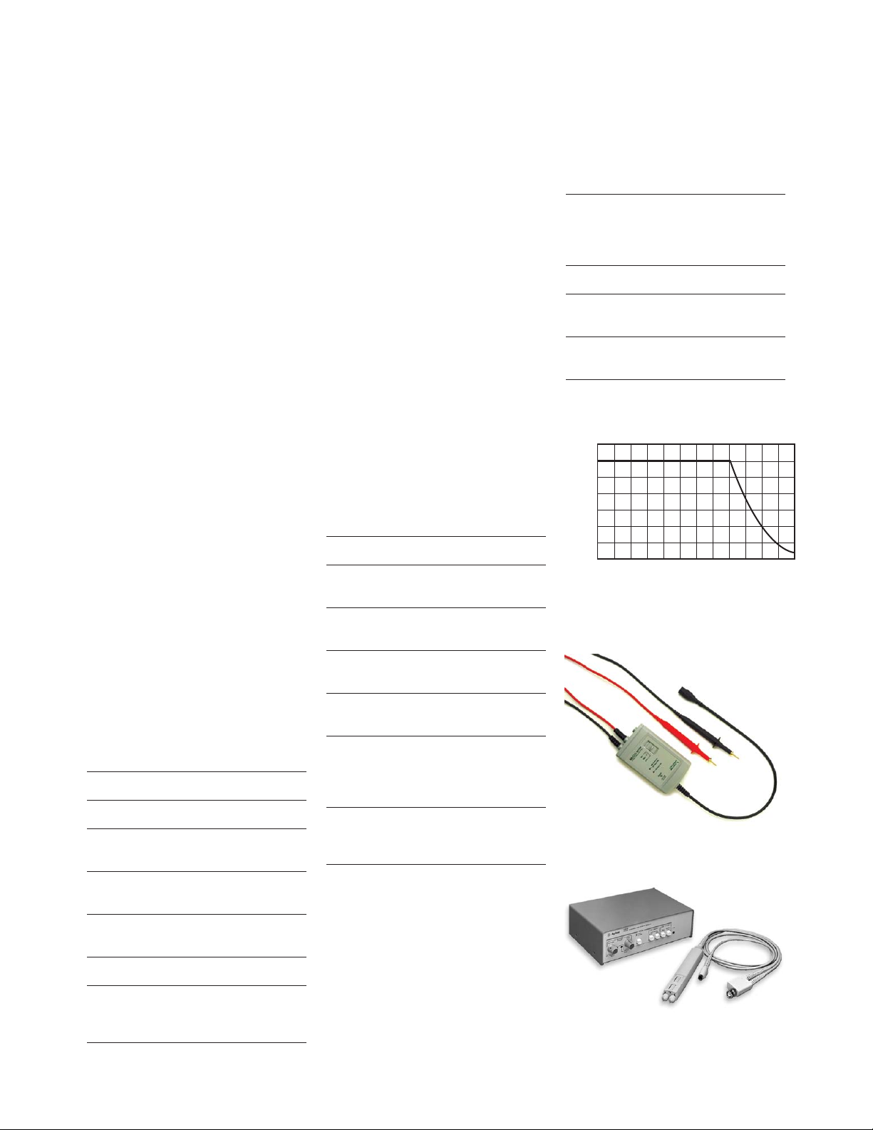
N2772A 20 MHz differential probe
Use the Agilent N2772A
differential probe with any of the
5000 or 6000 Series oscilloscopes
to safely measure floating circuits
with the oscilloscope grounded.
With 20 MHz bandwidth and
switchable attenuation of 20:1
and 200:1, it provides the versatility for a broad range of applications including high-voltage
circuits, motor speed controls,
power supply design, and electronic high-power converters.
Each probe comes with 2 sharp
probe tips for use on small
components and in tight places,
2 retractable probe hooks for
connecting to smaller wires and
through-hole components, and
2 alligator clips for use with
larger cables.
This probe requires a 9 V battery
or Agilent N2773A power supply.
Specifications for N2772A
differential probe
Bandwidth 20 MHz
Risetime 17.5 ns
Attenuation Ratio 20:1 and 200:1 selectable
via switch on probe
High CMRR 80 dB @ 60 Hz,
50 dB @ 1 MHz
Input Impedance Between inputs:
10 MΩ, 5 pF
Measure up to 600 V CAT III
Maximum Number 4
of Probes Supported
by 5000/6000 Series
1141A 200 MHz differential probe
The 1141A is a 1x FET differential probe with 200 MHz bandwidth and a 3000:1 CMRR. The
probe has a high-input resistance
and low input capacitance of 7 pF
to minimize circuit loading. The
1141A must be used with 1142A
probe control and power module,
which controls input coupling
modes dc, dc with variable offset,
and dc reject. Two attenuators,
10x and 100x are provided to
expand the linear differential
input range to ±30V. This probe
works with any 50 Ω input
oscilloscope including 5000 and
6000 Series.
Specifications for 1141A
differential probe
Bandwidth 200 MHz
Risetime 1.75 ns
(Calculated)
Attenuation Ratio 10:1 and 100:1
with attenuater
High CMRR 3000:1 at 1 MHz
10:1 at 100 MHz
Input Impedance Between inputs:
1 MΩ, 7 pF
Maximum Input 200 Vdc + peak ac
Voltage (probe alone)
500 Vdc + peak ac
(with attenuator)
Maximum Number 4
of Probes Supported
by 5000/6000 Series
Ordering information for Agilent
differential probes and power supply
N2772A 20 MHz differential
probe, supplied with a
retractable hook, sharp
probe tips and alligator clips
N2773A Power supply for N2772A
1141A 200 MHz differential
probe
1142A Probe control and .
power module for 1141A
Derating of each input for the N2772A
N2772 20 MHz differential probe
1141A 200 MHz differential probe
700
600
500
400
Vrms
300
200
100
0
0.01 0.02 0.05 0.1 0.2 0.5 1 2 5 10 20 50 100
MHz

8
High-Frequency Active Single-ended Probe
Agilent 1156A High-bandwidth Active Single-ended Voltage
• 1.5 GHz probe bandwidth;
< 233 ps rise/fall time
• 100 kΩ, 0.8 pF non-resonant
input impedance
• Small size for easier probing
• Compatible with 5000 and 6000
Series 300 MHz - 1 GHz only
The Agilent 1156A is a 1.5 GHz
active probe for use with Agilent
6000 Series or Infiniium oscilloscopes. Its high bandwidth
(1.5 GHz), low input capacitance
(< 0.8 pF) and high input resistance (100 kΩ) input minimizes
ultra low loading of the DUT,
making it ideal for the companion
for the 5000 or 6000 Series oscilloscopes. When used with the
5000 or 6000 Series, the 1156A
offers you a full bandwidth of the
scope to the probe tip, giving you
the accurate insight into your hispeed device.
Incorporating the most advanced
mechanical and electrical design
technologies, the 1156A provide
smaller, lighter and more rugged
probe tip that enable direct and
easy access to fine pitch ICs and
components. With the 1156A
probe, a damping resistor is
placed as close as possible to the
point being probed, which keeps
the input impedance from resonating low, and it also allows a
flat frequency resonance across
the entire bandwidth of the
probe. The 1156A is designed to
withstand 40 V peak AC input
and > 5 kV of ESD, so it will function reliably in adverse condition.
Key Specifications – Operating Characteristics
Probe Bandwidth (–3dB) > 1.5 GHz
Rise and Fall Time (10% to 90%) 233 psec
Calculated from tr=0.35/bandwidth
System Bandwidth (–3dB) 1156A with MSO/DSO610xA: 1 GHz
Input Capacitance 0.8 pF
Input Resistance 100 kΩ ±1%
Input Dynamic Range ±2.5 V
DC Attenuation 10:1 ± 3% before calibration
10:1 ± 1% after calibration
Offset Range ±15.0 V
Offset Accuracy < 3% of setting before calibration
1% of setting after calibration
Maximum Input Voltage 40 Vpeak, CAT I
ESD Tolerance > 5 kV from 100 pF, 300 Ω HBM
Maximum Number of Probes 4
Supported by 6000 Series
Ordering information for Agilent 1156A active probe
1156A 1.5 GHz single-ended active probe
Accessories
E2637A Precision measurement kit (includes 2 solderable ground sockets
with 2 green resistive signal pins)
E2638A Solderable-tip 5 cm resistive signal leads (10) with ground leads (3)
For more comprehensive information about 1156A active probe,
refer to the Agilent 1156/57/58A
Active Probes Product Overview
with Agilent literature number
5988-3361EN.
Agilent 1156A active probe with
accessories

9
Active Single-ended Probes
• Up to 800 MHz bandwidth
• 10:1 attenuation
• Compatible with 5000 and 6000
Series 300 MHz - 1 GHz
oscilloscopes
Agilent 1144A active probe
The 1144A features 800 MHz
bandwidth, 1 MΩ input resistance, 2 pF input capacitance, 10:1
attenuation and ±40 Vdc + peak
ac maximum input voltage. An
FET at the input allows a high
input resistance and low input
capacitance which minimizes the
loading of the circuit under test.
The output impedance of the
probe is 50 Ω which allows the
probe cable to be extended with
a 50 Ω coaxial cable. To use this
probe with 5000 or 6000 Series
oscilloscope, the 1142A power
supply is required. The
01144-61604 adapter can be used
with the power supply to provide
power for two channels of
active probing.
Specifications for 1144A active probe
Bandwidth 800 MHz
Risetime 440 ps
(Calculated)
Attenuation Ratio 10:1, ±2%
Input Resistance 1 MΩ, ±5%
Maximum Input ±40 Vdc + peak ac
Voltage
Input Capacitance* 2 pF (typical)
Input Dynamic 0 to ±7.0 V
Range*
Maximum Number 4
of Probes Supported
by 5000/6000 Series
* Operating characteristics
Agilent 1145A 2-channel active probe
The two-channel 1145A low-mass
active probe has a probe tip that
weighs less than 1 gram making
it ideal for attaching to find pitch
ICs and probing surface mount
components. The probe combines
high bandwidth (750 MHz), low
input capacitance (2 pF) and high
input resistance (1 MΩ). A versatile set of accessories are provided
and when used in conjunction
with the Wedge adapter, the
1145A provides a hands-free
solution for probing 0.5 mm and
0.65 mm IC packages. To use this
probe with 5000 or 6000 Series or
oscilloscope, the 1142A power
supply is required.
Specifications for 1145A active probe
Bandwidth 750 MHz
Risetime 470 ps
(Calculated)
Attenuation Ratio 10:1, ±3%
Input Resistance 1 MΩ, ±2%
Maximum Input ±40 Vdc + peak ac
Voltage
Input Capacitance* 2 pF (typical)
Input Dynamic 0 to ±6.0 V
Range*
Maximum Number 2
of Probes Supported
by 5000/6000 Series
* Operating characteristics
Ordering information for Agilent
active probes
1144A 800 MHz active probe
1145A 2-channel 750 MHz
active probe
1142A Power supply for
1144A and 1145A
01144-61604 Splitter cable assy
1144A active probe
1145A active probe

10
Mixed Signal Oscilloscope Logic Probes
• Compatible with all 40-pin logic
probe
• Flying leads offer flexibility
and convenience
MSO probes offer great value and
performance
These probes for the MSO6000A,
5462xD, and 5464xD Mixed Signal
Oscilloscopes (MSOs) are the
same ones used with Agilent
industry-leading high-performance
logic analyzers. This means we
can offer the best performance,
great value and access to the
industry’s broadest range of logic
probing accessories.
The 54620-68701 2 x 8-signal
logic probe is divided into two
sets of eight channels so you can
probe pins that are far apart and
work conveniently with only one
set if that’s all you require. For
optimal signal fidelity, connect
ground at each logic probe, in
addition to taking a common
ground to all eight signals via a
separate ground connector on the
probe pod. This probe is included
with MSO6000A MSOs.
Specifications for Agilent
54620-68701 logic probe
Input Impedance 100 kΩ
Input Capacitance 8 pF
The 10085-68701 16-channel logic
probe and termination adapter is
designed to make it easy to connect to industry-standard, 20-pin
board connectors. This probe
consists of a 2 m logic analyzer
probe cable and a 01650-63203
termination adapter that provides the proper RC networks
in a very convenient package.
Three 20-pin, low-profile, straight
board connectors are included.
Additional board connectors can
be ordered from Agilent or 3M.
Specifications for Agilent
10085-68701 logic probe and
termination adapter
Input Impedance 100 kΩ
Input Capacitance 12 pF
Ordering information for Agilent
logic probes
54620-68701 Logic probe with
2 x 8 flying leads.
Includes 20 IC clips
and 5 ground leads
10085-68701 Logic probe and
termination adapter
Board connectors
1251-8106 (3M part #2520-6002)
20-Pin, low profile
(straight)
1251-8473 (3M part #2520-5002)
20-Pin, low profile
(right angle)
54620-68701 Logic Probe
10085-68701 Logic Probe
Termination adapter included
in the 10085-68701

11
Mixed Signal Oscilloscope Logic Probes (continued)
6000 Series digital channels were
architected to be compatible with
a wide variety of probing accessories developed over 20 years for
logic analyzers. There’s a good
chance that the logic analyzer
accessories you already own work
with your MSO. With the addition
of an optional 40-pin cable,
01650-61607, the MSO accepts
numerous logic analyzer accessories:
• E5346A 34-channel Mictor
connector probe
• E5385A 34-channel Samtec
connector
• E5383A 16-channel flying lead
set
• 01650-63203 16-channel termination adaptor (also available
as a bundle of both the termination adapter and the 40-pin
cable with PN 10085-68701)
• E5404A 34-channel soft touch
pro connectorless probe
• E5394A 34-channel soft touch
connectorless probe
• E5396A 16-channel soft touch
connectorless probe
• Any other accessory that
connects to a logic analyzer
via a 40-pin cable
For logic accessories of greater
channel width than MSO digital
channels (> 16 channels), there
are 2 use models.
• Route up to sixteen signals to
the probe and don’t use the
additional probe channels.
• Route up to 32 signals to the
probe and measure 1⁄2 of them
at a time. Simply plug the
40-pin cable to the other side
of the probe to see the other
1⁄2 of the signals.
E5346A 34-channel Mictor connector
probe
E5385A 34-channel Samtec connector
probe
E5396A 16-channel soft touch
connectorless probe
12
Current Probes
• Up to 100 MHz bandwidth and
500 Arms current
• Hybrid technology to measure
ac and dc
• Compatible with any 1 MΩ
scope input
Accurate current measurements
without breaking the circuit
Compatible with any scope or
voltage measuring instruments
with BNC input, the 1146A and
N2780A Series current probes
offer accurate and reliable solutions for measuring dc and ac
currents. The probes use a hybrid
technology that includes a Hall
effect sensor, which senses the dc
current and a current transformer, which senses the ac current, making it unnecessary to
make an electrical connection to
the circuit.
1146A 100 kHz current probe
The 1146A ac/dc current probe
provides accurate display and
measurement of currents from
100 mA to 100 Arms, dc to
100 kHz, without breaking into
the circuit. A battery level indicator and overload indicator help
ensure proper readings. It connects directly to the scope
through a 2 m coaxial cable with
an insulated BNC.
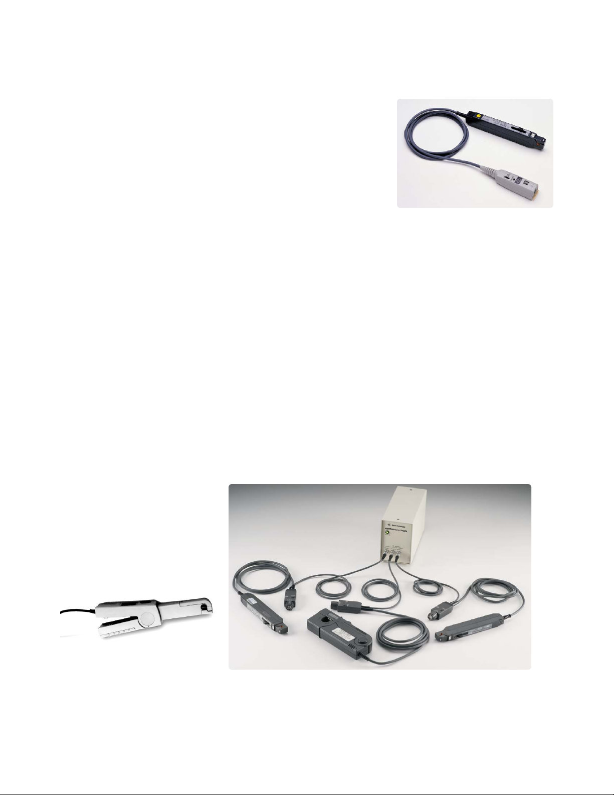
N2780A Series current probes with N2779A power supply
1147A 50 MHz Current Probe with
AutoProbe Interface
The 1147A is a wide bandwidth,
dc to 50 MHz current probe. The
probe offers flat frequency
response across the entire dc to
50 MHz bandwidth, low noise
(< 2.5 mArms) and low circuit
insertion loss. The 1147A probe
is compatible with the AutoProbe
interface, which completely
configures the oscilloscope for
the probe when used with the
5000 Series and 300 MHz - 1 GHz
6000 Series scope. Probe power is
provided by the scope, so there is
no need for an external power
supply.
N2780A/81A/82A/83A
2 MHz/10 MHz/50 MHz/100 MHz
current probe
The N2780A Series current
probes are high bandwidth,
active current probes, featuring
flat bandwidth, low noise
(< 2.5 mArms) and low circuit
insertion loss. In conjunction
with the power supply (model
N2779A), this probe can be used
with any oscilloscope having a
high-impedance BNC input. The
companion power supply N2779A
(3x 12 Vdc output) lets you connect three N2779As to a single
power supply.
1146A 100 kHz current probe
1147A 50 MHz current probe with
AutoProbe interface

13
Characteristics of the 1146A
current probe
Bandwidth* dc to 100 kHz (–3 dB)
Current Range* 100 mV/A:100 mA to
10 A peak
10 mV/A:1 to 100 A peak
Output Signal 1000 mV peak max
AC Current Accuracy*
Range: 100 mV/A (50 mA to
10 A peak)
Accuracy: 3% of reading ±50 mA
Range: 10 mV/A (500 mA to
40 A peak)
Accuracy: 4% of reading ±50 mA
Range: 10 mV/A (40 A to
100 A peak)
Accuracy: 15% max at 100 A
Noise Range 10 mV/A: 480 µV
Range 100 mV/A: 3 mV
Insertion Impedance (50/60 Hz) 0.01 Ω
Maximum 600 Vrms max.
Working Voltage
Maximum Common 600 Vrms max.
Mode Voltage
Influence of < 0.2 mA/A AC
Adjacent Conductor
Influence of 0.5% of reading at
Conductor Position 1 kHz in jaw
Battery 9 V alkaline (NEDA 1604A,
IEC 6LR61)
Low Battery Green LED when > 6.5 V
Battery Life 55 hours typical
* Characteristics marked with asterisks are specified
performance. Others are typical characteristics.
Note: Reference conditions 23°C ± 5°C, 20 to 75% relative humidity, dc to 1 kHz, probe zeroed, 1-minute
warmup, batteries at 9 V + 0.1 V, external magnetic field
<40 A/m, no dc component, no external current carrying
conductor, 1 MΩ/ 100 pF load, conductor centered in jaw.
Characteristics of the 1147A
current probe
Bandwidth (–3 dB) dc to 50 MHz
Risetime 7 ns or less
Maximum Current 15 A peak (ac+dc
(Continuous) components) RMS
Maximum Peak 30 A peak;
Current Non-continuous
50 A peak;
at pulse width of
10 µs or less
Output Voltage Rate 0.1 V/A
Amplitude ±1% rdg, ±1 mV (dc and
Accuracy 45 to 66 Hz, rated current)
Noise Equivalent to 2.5 mArms or
less (for 20 MHz bandwidth
measuring instrument)
Temperature ±2% or less (within a
Coefficient range of 0 °C to 40 °C or
for Sensitivity 32 °F to 104 °F)
Effect of External Equivalent to a maximum
Magnetic Fields of 20 mA (in a dc to 60 Hz,
400 A/m magnetic field)
Maximum 3 VA (with rated current)
Rated Power
Rated Supply Voltage dc ±12 V ±1 V
Diameter of 5 mm dia. (0.2” dia.)
Measurable
Conductors
Probe Interface BNC (N2774A)
AutoProbe interface
(1147A)
Cable Lengths Sensor cable:
Appox. 1.5 m (59.0”)
Power supply cable:
Appox. 1 m (39.4”)
Maximum Number 2 (1147A)
of Probes Supported
Note: The above specifications are guaranteed at
23 °C ± 3 °C (or 73 °F ± 5 °F)
Current Probes (continued)
Characteristics of N2780A Series
current probes
Bandwidth (–3dB) dc to 2 MHz (N2780A)
dc to 10 MHz (N2781A)
dc to 50 MHz (N2782A)
dc to 100 MHz (N2783A)
Maximum Current 500 A (N2780A)
(Continuous) 150 A (N2781A)
30 A (N2782A/N2783A)
Maximum Peak 700 A peak (N2780A)
Current 300 A peak (N2781A)
(Non-continuous) 50 A peak
(N2782A/N2783A)
Output Voltage 0.01 V/A (N2780A/N2781A)
Rate 0.1 V/A (N2782A/N2783A)
Amplitude ±1.0 % rdg ±500 mA
Accuracy (N2780A)
±1.0 % rdg ±100 mA
(N2781A)
±1.0 % rdg ±10 mA
(N2782A)
±1.0 % rdg ±10 mA
(N2783A)
Ordering information for Agilent
current probes
1146A 100 kHz current probe
1147A 50 MHz current probe
with AutoProbe interface
N2780A 2 MHz current probe
N2781A 10 MHz current probe
N2782A 50 MHz current probe
N2783A 100 MHz current probe .
N2779A 3-channel power supply .
for N2780A/81A/82A/83A
For more information about the
N2780A Series current probes,
refer to the Agilent N2780A
Series current probe data sheet,
Agilent literature number
5989-6432EN.

14
Wedge Probe Adapters
• Easy connection to surface
mount ICs
• Safe, with no chance of shorting
• Mechanically non-invasive contact
• 3-, 8-, and 16-signal versions
• Supports 0.5 mm and 0.65 mm
TQFP and PQFP packages
Problem-free probing
The Agilent Wedge Probe Adapter
eliminates many of the frustrations associated with probing
surface mount components. If
you’ve ever accidentally shorted
IC pins together, experienced
electrical and/or mechanical
problems with soldering small
wires onto leads, or gotten frustrated juggling multiple probes
while you’re trying to operate
your scope, the Wedge was
designed with you in mind.
Make the inaccessible accessible
When you use the Wedge, you
don’t have to worry about shorting IC pins together on a delicate
component — or worse yet on an
irreplaceable prototype. The
Wedge is easy to insert and it
stays put. There’s no need to
solder small wires onto leads.
The Wedge is mechanically noninvasive, so you won’t damage the
legs of the IC. Instead, you’ll have
easy access to hard-to-reach
components.
Electrical reliability
The Wedge makes two contact
points with each leg of the IC.
This redundant physical connection increases the electrical
reliability of the connection. And
the Wedge’s low capacitance and
inductance provides superior
performance to many other
alternatives.
IC clip kits
An inexpensive solution for probing fine-pitch ICs, the 10072A
SMT Kit includes ten IC clips and
two dual-lead adapters that connect the clips directly to 10070family probes.
The 10075A 0.5 mm IC clip kit is
ideal for connecting to IC’s as fine
as 0.5 mm. The clip body allows
many clips to be mounted sideby-side. The kit includes four
0.5 mm IC clips and two dual-lead
adapters that connect the IC clips
directly to 10070-family probes.
Agilent Wedge electrical
characteristics
Operating Voltage < 40 V dc + peak ac
Operating Current 0.5 A maximum
Capacitance 2 pF typical (all except
Between Contacts Agilent E2643A/44A)
4.33 pF typical at 1 MHz
(Agilent E2643A/44A)
Self-Inductance 15 nH typical (all except
Agilent E2643A/44A)
37 nH typical at 1 MHz
(Agilent E2642A/44A)
Cross Coupling –31 dB typical at 100 MHz
(Agilent E2643A/44A)
Contact Resistance < 0.1 Ω
Ordering information
E2613A 0.5 mm Wedge probe
adapter 3-signal, qty 1
E2613B 0.5 mm Wedge probe
adapter, 3-signal, qty 2
E2614A 0.5 mm Wedge probe
adapter, 8-signal, qty 1
E2643A 0.5 mm Wedge probe
adapter, 16-signal, qty 1
E2615A 0.65 mm Wedge probe
adapter, 3-signal, qty 1
E2615B 0.65 mm Wedge probe
adapter, 3-signal, qty 2
E2616A 0.65 mm Wedge probe
adapter, 8-signal, qty 1
E2644A 0.65 mm Wedge probe
adapter, 16-signal, qty 1
10072A SMT kit for 10070 probe
family
10075A 0.5 mm IC clip kit

15
PC Connectivity
Get scope data into your PC with
Agilent IntuiLink without programming
• Ideal for documentation
and archiving
• Works in familiar Microsoft®Excel
and Word environments
• Leverage the power of Excel for
data analysis and advanced
graphing
• ActiveX controls provided for more
flexible scope programming
• Compatible with 5000 and
6000 Series
To simplify the task of transferring images and waveform data
to your PC, Agilent IntuiLink
software is offered free for all
5000 and 6000 Series scopes.
IntuiLink Toolbar provides easy
access to the scope data and
images from within your standard
PC applications. You work in a
familiar environment at all times,
using PC applications such as
Microsoft Excel or Word to analyze, interpret, display, print, and
document the data you get from
the scope. The IntuiLink toolbar
makes it easy, providing a simple
way to download data and
screenshots into a spreadsheet or
document. You can also save the
scope settings and retrieve them
later to reproduce difficult setups
like glitch capture and complex
triggering.
Simple transfer of images and data with IntuiLink Toolbar
Minimum Operating System
requirements:
• Windows 95/98, or Me
• Windows NT 4.0 (with Service
Pack 4 or greater, obtain at
www.microsoft.com)
• Windows 2000
• Windows XP
Minimum MS Office application
requirements:
• Microsoft Office 2000 (Word or
Excel) or
• Microsoft Office XP
• Microsoft Office 2003
IntuiLink Data Capture software
for transferring megabytes of data
to PC
The IntuiLink Data Capture is a
standalone software for downloading waveform data and
screen image from 5000 or 6000
Oscilloscopes to the PC via USB,
LAN or GPIB interface. It provides the capability to transfer
full deep memory data out of the
scope. The IntuiLink Toolbar
application limits the size of
acquisition data available to a
maximum of 50,000 points
regardless of actual number of
acquisition points on the screen.
With the IntuiLink Data Capture,
the amount of points transferred
will be the actual number of
acquisition points currently
displayed or you may select the
number of points to download.
Unlike the IntuiLink Toolbar, it is
not based on Microsoft Excel or
Words. However you may still
copy and paste the data on to the
Microsoft applications for manipulating or charting the data.
For more information or free
download of the software, visit

16
Miscellaneous Accessories
Testmobile
The sturdy Agilent 1180CZ
Testmobile for use with 6000
Series oscilloscope makes sharing
your scope easy. Its large wheels
make it easy to roll from place to
place. For use with the Agilent
6000 Series scope, the 1180CZ
testmobile scope cart with the
N2919A bracket provides convenient mobility and secure mounting of your scope.
Specifications for the Agilent
Testmobiles
1180CZ
Total Load Capacity 59 kg (130 lbs)
Tilt Tray 45.7 cm wide x
45.7 cm deep
Carrying Cases
The Agilent N2760A soft carrying
case and N2917B hard carrying
case make transporting and shipping your 5000 and 6000 Series
oscilloscope safe and simple. A
scope and other accessories fit
neatly inside the padded shell for
shipment.
Specifications for the Agilent
carrying cases
N2917B for 5000 and 6000 Series
Dimensions 45 cm x 42 cm x 31 cm
(W x H x D)
Material Tough ABS Plastic
N2760A for 5000 Series only
Dimensions 39 cm x 27 cm x 22 cm
(W x H x D)
Material 600 Denier Polyfoam with
Tricot Foam laminate with
interior pack cloth
Rackmount Kit
The Agilent N2916B Rackmount
Kit positions your 5000 and 6000
Series scope in the center of the
rack. Each kit includes a custom
shelf with rails, 6 BNC passthroughs and all necessary
screws.
Ordering information
1180CZ Testmobile (6000 Series)
N2919A Bracket for 1180CZ
testmobile and 6000
Series scope
N2917B Hard carrying case
(5000 and 6000 Series)
N2760A Soft carrying case
(5000 Series)
N2916B Rackmount Kit $
(5000 and 6000 Series)
N2760A Soft carrying case for the 5000 series
N2916B Rackmount kit for 5000/6000 Series

Microsoft is a U.S. registered trademark of Microsoft
Corporation.
www.agilent.com/find/open
Agilent Open simplifies the process of
connecting and programming test systems
to help engineers design, validate and
manufacture electronic products. Agilent
offers open connectivity for a broad range
of system-ready instruments, open industry
software, PC-standard I/O and global
support, which are combined to more
easily integrate test system development.
www.agilent.com
For more information on Agilent
Technologies’ products, applications or
services, please contact your local Agilent
office. The complete list is available at:
www.agilent.com/find/contactus
Phone
Americas
Canada (877) 894-4414
Latin America 305 269 7500
United States (800) 829-4444
Asia Pacific
Australia 1 800 629 485
China 800 810 0189
Hong Kong 800 938 693
India 1 800 112 929
Japan 81 426 56 7832
Korea 080 769 0800
Malaysia 1 800 888 848
Singapore 1 800 375 8100
Taiwan 0800 047 866
Thailand 1 800 226 008
Europe
Austria 0820 87 44 11
Belgium 32 (0) 2 404 93 40
Denmark 45 70 13 15 15
Finland 358 (0) 10 855 2100
France 0825 010 700
Germany 01805 24 6333*
*0.14€/minute
Ireland 1890 924 204
Italy 39 02 92 60 8484
Netherlands 31 (0) 20 547 2111
Spain 34 (91) 631 3300
Sweden 0200-88 22 55
Switzerland (French)
44 (21) 8113811 (Opt 2)
Switzerland (German)
0800 80 53 53 (Opt 1)
United Kingdom 44 (0) 7004 666666
Other European countries:
www.agilent.com/find/contactus
Revised: March 23, 2007
Product specifications and descriptions
in this document subject to change
without notice.
© Agilent Technologies, Inc. 2005, 2007
Printed in USA, April 30, 2007
5968-8153EN
www.agilent.com/find/emailupdates
Get the latest information on the products
and applications you select.
www.agilent.com/find/agilentdirect
Quickly choose and use your test
equipment solutions with confidence.
Agilent Email Updates
Remove all doubt
Our repair and calibration services
will get your equipment back to you,
performing like new, when promised.
You will get full value out of your Agilent
equipment throughout its lifetime.
Your equipment will be serviced by
Agilent-trained technicians using the
latest factory calibration procedures,
automated repair diagnostics and
genuine parts. You will always
have the utmost confidence in your
measurements.
Agilent offers a wide range of additional
expert test and measurement services
for your equipment, including initial
start-up assistance onsite education
and training, as well as design, system
integration, and project management.
For more information on repair and
calibration services, go to
www.agilent.com/find/removealldoubt
www.lxistandard.org
LXI is the LAN-based successor to GPIB,
providing faster, more efficient connectivity.
Agilent is a founding member of the LXI
consortium.
Agilent Direct
Agilent
Open
 Loading...