

Page 1

User’s Guide
Publication Number 54622-97002
March 2000
For Safety Information, Warranties, and Regulatory information,
see the pages behind the Index.
© Copyright Agilent Technologies 2000
All Rights Reserved
Agilent 54621A/22A/24A
Oscilloscopes and
Agilent 54621D/22D
Mixed-Signal Oscilloscopes
Page 2

The Oscilloscopes at a Glance
Display shows current input signals
• All analog and digital (54621D/22D)
channels displayed in main and
delayed mode
• Indicators for channel, time base,
digital (54621D/22D) channel activity,
trigger and acquisition status
• Softkey labels
• Measurement results
Digital channel controls select, position,
and label inputs (54621D/22D)
• Turn channels on or off individually or
in groups of 8
• Rearrange order of channels to group
related signals
• Create and display labels to identify
channels
General controls measure, save and
restore results, and configure the
oscilloscope
• Waveform math including FFT,
subtract, multiply, integrate, and
differentiate
• Use Quick meas to make automatic
measurements
• Use cursors to make manual
measurements
• Save or recall measurement
configurations or previous results
• Autoscale performs simple onebutton setup of the oscilloscope
Run control keys begin and end data
acquisition
• Run/Stop starts and stops continuous
acquisitions
• Single performs one acquisition
• Infinite persistence accumulates and
displays the results of multiple
acquisitions
Trigger keys define what data the
oscilloscope will trigger on
• Source key allows conventional
oscilloscope triggering
• Modes include Edge, Pulse Width,
Pattern, TV, Sequence, I
Duration triggering.
Softkeys extend the functionality of
command keys
Select measurement types, operating
modes, trigger specifications, label data,
and more
Channel inputs through a flexible
probing system (54621D/22D)
• Sixteen channels through a dual 8channel cable with micro-clips
• Set logic levels as TTL, CMOS, ECL, or
to a user-definable voltage
Utilities
• Dedicated parallel printer port,
controller operation, floppy disk
storage
2
C, and
Horizontal Controls select sweep speed
and delay parameters
• Sweep speeds from 5 ns to 50 s/div
• Delay control moves waveform
display to point of interest
• Delayed mode and delay allow
zooming in to show a portion of
waveform in detail (split screen)
ii
Built in Quick Help system
• Press and hold any key front-panel key
or softkey to get help in 9 languages.
Page 3

In This Book
This manual will guide you in using the oscilloscopes. This manual is organized
in the following chapters:
Chapter 1 Getting Started—inspecting, cleaning, and setting up your
oscilloscope, using Quick Help.
Chapter 2 Front-panel Overview—A quick start guide to get you familiarize
you with the front-panel operation.
Chapter 3 Triggering the Oscilloscope—how to trigger the oscilloscope using
all the various modes.
Chapter 4 MegaZoom Concepts and Oscilloscope Operation—acquiring
waveforms, horizontal and vertical operation, using digital channels.
Chapter 5 Making Measurements—capturing data, using math function,
making measurement with cursors and automatic measurements.
Chapter 6 Utilities—configuring the I/O, print settings, Quick Help, floppy
disk operations, user cal and self cal, setting the clock and screen saver.
Chapter 7 Performance Characteristics
iii
Page 4

iv
Page 5

Contents
1 Getting Started
Setting up the Oscilloscope 1-4
To inspect package contents 1-5
To inspect options and accessories 1-7
To clean the oscilloscope 1-10
To adjust the handle 1-11
To power-on the oscilloscope 1-12
To adjust the display intensity 1-13
To connect the oscilloscope probes 1-14
To use the digital probes (mixed-signal oscilloscope only) 1-15
To connect a printer 1-19
To connect an RS-232 cable 1-19
To verify basic oscilloscope operation 1-20
Getting started using the oscilloscope interface 1-21
Using Quick Help 1-23
Selecting a language for Quick Help when the oscilloscope starts up 1-23
Selecting a language for Quick Help after you have been operating the
oscilloscope 1-24
Loading a language from floppy disk 1-25
2 Front-Panel Overview
Important Oscilloscope Considerations 2-3
54600-series Oscilloscope1 Front Panels 2-7
Front-Panel Operation 2-10
Interpreting the display 2-11
To use analog channels to view a signal 2-12
To use digital channels to view a signal 2-13
To display signals automatically using Autoscale 2-14
To apply the default factory configuration 2-15
To adjust analog channel vertical scaling and position 2-16
To set the vertical expand reference for the analog signal 2-17
Contents-1
Page 6

Contents
To set analog channel probe attenuation factor 2-17
To display and rearrange the digital channels 2-18
To operate the time base controls 2-19
To start and stop an acquisition 2-20
To make a single acquisition 2-20
To use delayed sweep 2-21
To make cursor measurements 2-22
To make automatic measurements 2-23
To modify the display grid 2-24
To print the display 2-24
3 Triggering the Oscilloscope
Selecting Trigger Modes and Conditions 3-3
To select the Mode and Coupling menu 3-3
To select a trigger mode: Auto Level, Auto, Normal 3-4
To select trigger Coupling 3-6
To select Noise Reject and HF Reject 3-6
To set holdoff 3-7
Trigger Types 3-9
To use edge triggering 3-10
To use pulse width triggering 3-12
To use pattern triggering 3-15
To use duration triggering 3-17
To use I2C triggering 3-20
To use sequence triggering 3-23
To use TV triggering 3-29
The Trig Out connector 3-39
Contents-2
Page 7

4 MegaZoom Concepts and Oscilloscope Operation
MegaZoom Concepts 4-3
Deep Memory 4-4
Oscilloscope Responsiveness 4-5
Display Update Rate 4-6
To setup the Analog channels 4-7
To setup the Horizontal time base 4-10
Acquisition Modes 4-16
Display modes 4-20
Pan and Zoom 4-22
To pan and zoom a waveform 4-23
Run/Stop/Single/Infinite Persistence Operation 4-24
Acquiring Data 4-25
Memory Depth/Record Length 4-26
To run and stop an acquisition 4-27
To take a single trace 4-27
To capture a single event 4-28
To use infinite persistence 4-29
To use infinite persistence to store multiple repetitive events 4-29
To clear the waveform display 4-30
Contents
Configuring the Mixed-Signal Oscilloscope 4-31
To display digital channels using Autoscale 4-31
Interpreting the digital waveform display 4-32
To display and rearrange the digital channels 4-33
To turn individual channels on and off 4-34
To force all channels on or all channels off 4-35
To change the display size of the digital channels 4-35
To change the logic threshold for digital channels 4-36
Using Digital Channels to Probe Circuits 4-37
Contents-3
Page 8

Contents
Using Labels on the Mixed-Signal Oscilloscope 4-41
To turn the label display on or off 4-42
To assign a predefined label to a channel 4-43
To define a new label 4-44
To reset the label library to the factory default 4-46
Saving and Recalling Traces and Setups 4-47
To Autosave traces and setups 4-48
To save traces and setups to internal memory or to overwrite an existing
floppy disk file 4-49
To save traces and setups to a new file on the floppy disk 4-50
To recall traces and setups 4-51
Saving (printing) screen images to floppy disk 4-52
Recalling the factory default setup 4-53
5 Making Measurements
Capturing Data 5-3
To use delayed sweep 5-4
To reduce the random noise on a signal 5-6
To capture glitches or narrow pulses with peak detect and infinite
persistence 5-10
To use the Roll horizontal mode 5-11
To use the XY horizontal mode 5-12
Math Functions 5-16
Multiply 5-17
Subtract 5-18
Differentiate 5-19
Integrate 5-21
FFT Measurement 5-23
Contents-4
Page 9

Cursor Measurements 5-29
To make cursor measurements 5-30
Automatic Measurements 5-35
Making automatic measurements 5-36
Making time measurements automatically 5-37
Making voltage measurements automatically 5-40
Making overshoot and preshoot measurements 5-43
6 Utilities
To configure Quick Help languages 6-3
To configure a printer 6-5
To use the floppy disk 6-7
To set up the I/O port to use a controller 6-8
To set the clock 6-10
To set up the screen saver 6-11
To perform service functions 6-12
To set other options 6-14
7 Performance Characteristics
Contents
Performance Characteristics 7-3
Index
Contents-5
Page 10

Contents-6
Page 11

1
Getting Started
Page 12

Getting Started
When you use the oscilloscopes to help test and troubleshoot your
systems, you may do the following:
• Prepare the oscilloscope by connecting it to power and setting up the
handle and screen intensity as desired.
• Define the measurement problem by understanding the parameters
of the system you wish to test, and the expected system behavior.
• Set up channel inputs by connecting the probes to the appropriate
signal and ground nodes in the circuit under test.
• Define the trigger to reference the waveform data at a specific event
of interest.
• Use the oscilloscope to acquire data, either in continuous or singleshot fashion.
• Examine the data and make measurements on it using various
features.
• Save the measurement or configuration for later re-use or comparison
with other measurements.
Repeat the process as necessary until you verify correct operation or
find the source of the problem.
MegaZoom Technology Operates with Untriggered Data
With the MegaZoom technology built into the oscilloscope, you can
operate the oscilloscope with untriggered data. All you do is press
Single while in Auto trigger mode, then examine the data to set up a
or
trigger.
1-2
Run
Page 13

Getting Started
The oscilloscope’s high-speed display can be used to isolate infrequently
changing signals. You can then use the characteristics of these signals
to help refine the trigger specification. For more information on
triggering, data acquisition, data examination and measurement, and
configuration, see the later chapters.
Using the Oscilloscope, and Refining the Trigger Specification
1-3
Page 14

Setting up the Oscilloscope
To prepare your oscilloscope for use, you need to do the following tasks.
After you have completed them, you will be ready to use the oscilloscope.
In the following topics you will:
• inspect package contents
• inspect options and accessories
• learn how to clean the oscilloscope
• adjust the handle
• power-on the oscilloscope
• adjust the display intensity
• connect the oscilloscope probes
• connect the digital probes (with 54621D and 54622D)
• connect a printer
• connect a RS-232 cable
• verify basic oscilloscope operation
• get started using the oscilloscope interface
• learn how to use Quick Help
1-4
Page 15

Getting Started
To inspect package contents
To inspect package contents
❏ Inspect the shipping container for damage.
If your shipping container appears to be damaged, keep the shipping container
or cushioning material until you have inspected the contents of the shipment
for completeness and have checked the oscilloscope mechanically and
electrically.
❏ Verify that you received the following items and any optional accessories in
the oscilloscope packaging (see figure following).
• 54600-Series Oscilloscope (54621A, 21D, 22A, 22D, or 24A)
• 10074C 10:1 passive probes:
(2) for 54621A, 21D, 22A, or 22D oscilloscopes
(4) for 54624A oscilloscope
• 54620-68701 digital probe kit (for 54621D or 22D)
• Accessory pouch and front-panel cover (standard for 54622A, 22D, and 24A)
(optional on 54621A and 21D; order N2726A)
• Power cord (see table 1-3)
• BenchLinkXL 54600 software and RS-232 cable (for 54622A, 22D, or 24A)
BenchLink XL 54600 software is available free on the web at:
www.agilent.com/go/megazoom
RS-232 cable may be ordered separately, part number 34398A
If anything is missing, contact your nearest Agilent Sales Office. If the shipment
was damaged, contact the carrier, then contact the nearest Agilent Sales Office.
❏ Inspect the oscilloscope
• If there is mechanical damage or a defect, or if the oscilloscope does not
operate properly or does not pass the performance tests listed in the Service
Guide, notify your Agilent Sales Office.
• If the shipping container is damaged, or the cushioning materials show signs
of stress, notify the carrier and your Agilent Sales Office. Keep the shipping
materials for the carrier’s inspection. The Agilent Sales Office will arrange
for repair or replacement at Agilent’s option, without waiting for claim
settlement.
1-5
Page 16

Getting Started
To inspect package contents
54600-Series Oscilloscope
Accessories pouch and
front-panel cover**
Power cord
54620-68701 digital probe kit*
54620-61801 16-channel cable
BenchlinkXL 54600 software
and serial cable**
5959-9334 2” Ground
lead (qty 5)
5090-4356 Clip
(qty 20)
10074C Probes
54621D /22D only
* 54622A/22D/24A only
Package contents for 54600-Series Oscilloscopes
1-6
s
sa
Page 17

Getting Started
To inspect options and accessories
To inspect options and accessories
❏ Verify that you received the options and accessories you ordered and that none
were damaged.
If anything is missing, contact your nearest Agilent Sales Office. If the shipment
was damaged, or the cushioning materials show signs of stress, notify the carrier
and your Agilent Sales Office.
Some of the options and accessories available for the 54600-Series Oscilloscopes
are listed in tables 1-1 and 1-2. Contact your Agilent Sales Office for a complete
list of options and accessories.
Table 1-1
Options available
Option Description
003 Shielding Option for use in severe environments or with sensitive devices under
test–shields both ways (in and out):
RS-03 magnetic interface shielding added to CRT, and
RE-02 display shield added to CRT to reduce radiated interference.
0B0 Delete manuals
A6J ANSII Z540 compliant calibration with test data
W32 3-year, customer-return calibration service
W34 3-year, customer-return standard compliance calibration service
W50 Additional 2-year warranty (5 years total)
W52 5-year, customer-return calibration service
W54 5-year customer-return standard compliance calibration service
See table 1-3 for power cord options
1-7
Page 18

Getting Started
To inspect options and accessories
Table 1-2
Accessories available
Model Description
1146A Current probe, ac/dc
1183A Testmobile scope cart
1185A Carrying Case
1186A Rackmount Kit
10070C 1:1 Passive Probe with ID
10072A Fine-pitch probe kit
10073B 10:1 500 MHz probe with ID
10075A 0.5 mm IC clip kit
10076A 100:1, 4 kV 250 MHz probe with ID
10085A 16:16 logic cable and terminator (for use with 54621D/22D)
10089A 16:2 x 8 logic input probe assembly (shipped standard with 54621D/22D)
10100C 50
10833A GPIB cable, 1 m long
34398A RS-232 cable (standard with 100 MHz models)
E2613B 0.5 mm Wedge probe adapter, 3-signal, qty 2
E2614A 0.5 mm Wedge probe adapter, 8-signal, qty 1
E2615B 0.65 mm Wedge probe adapter, 3-signal, qty 2
E2616A 0.65 mm Wedge probe adapter, 8-signal, qty 1
E2643A 0.5 mm Wedge probe adapter, 16-signal, qty 1
E2644A 0.65 mm Wedge probe adapter, 16-signal, qty 1
N2726A Accessory pouch and front-panel cover (standard with 100 MHz models)
N2727A Thermal printer and pouch
N2728A 10 rolls of thermal printer paper
N2757A GPIB Interface Module
N2772A 20 MHz differential probe
N2773A Differential probe power supply
Ω Termination
1-8
Page 19

Getting Started
To inspect options and accessories
Table 1-3
Power Cords
Plug Type Cable Part No. Plug Description Length in/cm Color
Opt 903 (U.S.A.)
124V **
8120-1378 Straight (NEMA5-15P*) 90/228 Jade Gray
Opt 900 (U.K.)
250V
Opt 901 (Australia)
250V
Opt 902 (Europe)
250V
Opt 906 (Switzerland)
250V
Opt 912 (Denmark)
220V
Opt 917 (Africa
)250V
Opt 918 (Japan)
100V
8120-1351 Straight (BS136A*) 90/228 Gray
8120-1369 Straight (NZSS198/ASC*) 79/200 Gray
8120-1689
8120-2857
8120-2104 Straight (SEV1011*) 79/200 Mint Gray
8120-2957 Straight (DHCK107*) 79/200 Mint Gray
8120-4600 Straight (SABS164) 79/200 Jade Gray
8120-4753 Straight Miti 90/230 Dark Gray
Straight (CEE7-Y11*)
Straight (Shielded)
79/20079/200 Mint Gray
Coco Brown
* Part number shown for plug is industry identifier for plug only.
Cable part number shown is Agilent part number for complete cable including plug.
** These cords are included in the CSA certification approval for the equipment.
1-9
Page 20

Getting Started
To clean the oscilloscope
To clean the oscilloscope
1 Disconnect power from the instrument.
CAUTION Do not use too much liquid in cleaning the oscilloscope. Water can enter the
front-panel keyboard, control knobs, or floppy disk damaging sensitive
electronic components.
2 Cl ean t he os cillos cope w ith a s of t cloth damp ened w ith a mild so ap and
water solution.
3 Make sure that the instrument is completely dry before reconnecting to
a power source.
1-10
Page 21

Getting Started
To adjust the handle
To adjust the handle
1 Grasp the handle pivot points on each side of the instrument and pull
the pivot out until it stops.
54622D
Agilent
s
MIXED SIGNAL OSCILLOSCOPE
CHANNEL
Select
Time/Div
150
5 ns1 s
INPUTS
2 Without releasing the pivots, swivel the handle to the desired position.
Then release the pivots. Continue pivoting the handle until it clicks into
a set position.
1-11
Page 22

Getting Started
To power-on the oscilloscope
To power-on the oscilloscope
1 Connect the power cord to the rear of the oscilloscope, then to a
suitable ac voltage source.
The oscilloscope power supply automatically adjusts for input line voltages in
the range 100 to 240 VAC. Therefore, you do not need to adjust the input line
voltage setting. The line cord provided is matched to the country of origin.
Ensure that you have the correct line cord. See table 1-3
2 Press the power switch.
Tr i gg er ou t
~5V
Some front panel key light will come on and the oscilloscope will be operational
in about 5 seconds.
1-12
Page 23

Figure 1-1
Getting Started
To adjust the display intensity
To adjust the display intensity
The Intensity control is at the lower left corner of the front panel.
• To decrease display intensity, rotate the Intensity control counterclockwise.
• To increase display intensity, rotate the Intensity control clockwise.
BrightDim
Intensity control
The grid or graticule intensity on the display can be adjusted by pressing the
Display key, then turn the Entry knob (labeled on the front panel) to adjust
the Grid control.
1-13
Page 24

Getting Started
To connect the oscilloscope probes
To connect the oscilloscope probes
1 Connect the 10074C 1.5-meter, 10:1 oscilloscope probe to the analog
channel 1 or 2 BNC connector input on the oscilloscope, or channel 1
through channel 4 on the 54624A.
Maximum input voltage for analog inputs:
CAT I 300 Vrms, 400 Vpk
CAT II 100 Vrms, 400 Vpk
with 10074C 10:1 probe: CAT I 500 Vpk, CAT II 400 Vpk
2 Connect the retractable hook tip on the probe tip to the circuit point of
interest. Be sure to connect the probe ground lead to a ground point on
the circuit.
The probe ground lead is connected to the oscilloscope chassis and the ground
wire in the power cord. If you need to connect the ground lead to a point in the
circuit that cannot be grounded to power ground, consider using a differential
probe.
1-14
Page 25

Getting Started
To use the digital probes (mixed-signal oscilloscope only)
To use the digital probes (mixed-signal oscilloscope
only)
1 If you feel it’s necessary, turn off the power supply to the circuit under
test.
Off
Turning off power to the circuit under test would only prevent damage that
might occur if you accidentally short two lines together while connecting
probes. You can leave the oscilloscope powered on because no voltage appears
at the probes.
2 Connect the digital probe cable to D15 - D0 connector on the front panel
of the mixed-signal oscilloscope. The digital probe cable is indexed so
you can connect it only one way. You do not need to power-off the
oscilloscope.
Use only the Agilent part number 54620-68701 digital probe kit supplied with
the mixed-signal oscilloscope. Additional probe kits may be ordered by
specifying Agilent part number 10089A.
1-15
Page 26

Getting Started
To use the digital probes (mixed-signal oscilloscope only)
3 Connect a clip to one of the probe leads. Be sure to connect the ground
lead. (Other probe leads are omitted from the figure for clarity.)
Clip
4 Connect the clip to a node in the circuit you want to test.
1-16
Page 27

Getting Started
To use the digital probes (mixed-signal oscilloscope only)
5 For high-speed signals, connect a ground lead to the probe lead, connect
a clip to the ground lead, and attach the clip to ground in the circuit
under test.
Signal Lead
Ground Lead
Clip
6 Connect the ground lead on each set of channels, using a probe clip.
The ground lead improves signal fidelity to the instrument, ensuring
accurate measurements.
Channel
Pod Ground
Circuit
Ground
1-17
Page 28

Getting Started
To use the digital probes (mixed-signal oscilloscope only)
7 Repeat steps 3 through 6 until you have connected all points of interest.
Signals
Ground
8 If you need to remove a probe lead from the cable, insert a paper clip
or other small pointed object into the side of the cable assembly, and
push to release the latch while pulling out the probe lead.
Replacement parts are available. See the Replaceable Parts chapter in the
Service Guide for details.
1-18
Page 29

Getting Started
To connect a printer
To connect a printer
The oscilloscope connects to a parallel printer through the Parallel output
connector on the rear of the oscilloscope. You will need a parallel printer cable
to connect to the printer.
1 Attach the 25-pin small “D” connector to the Parallel output connector
on the rear of the oscilloscope. Tighten the thumbscrews on the cable
connector to secure the cable.
2 Attach the larger 36-pin “D” connector to the printer.
3 Set up the printer configuration on the oscilloscope.
aPress the Utility key, then press the Print Confg softkey.
bPress the Print to: softkey and set the interface to Parallel.
cPress the Format softkey and select your printer format from the list.
For more information on printer configuration, refer to the “Utilities” chapter.
To connect an RS-232 cable
The oscilloscope can be connected to a controller or a pc through the RS-232
connector on the rear of the oscilloscope. An RS-232 cable is shipped with each
54622A/22D/24A oscilloscope and may be purchased for the 54621A/21D
oscilloscopes.
1 Attach the 9-pin “D” connector on the RS-232 cable to the RS-232
connector on the rear of the oscilloscope. Tighten the thumbscrews on
the cable connector to secure the cable
2 Attach the other end of the cable to your controller or pc.
3 Set up the RS-232 configuration on the oscilloscope.
aPress the Utility key, then press the I/O softkey.
bPress the Controller softkey and select RS-232.
cPress the Baud softkey and set the baud rate to match your controller or pc.
dPress the XON DTR softkey and set the handshake to match your controller
or pc.
For more information on RS-232 configuration, refer to the “Utilities” chapter.
1-19
Page 30

Getting Started
To verify basic oscilloscope operation
To verify basic oscilloscope operation
1 Connect an oscilloscope probe to channel 1.
2 Attach the probe to the Probe Comp output on the lower-right side of
the front panel of the oscilloscope.
Use a probe retractable hook tip so you do not need to hold the probe.
3Press the Save/Recall key on the front panel, then press the Default Setup
softkey under the display.
The oscilloscope is now configured to its default settings.
4Press the Autoscale key on the front panel.
You should then see a square wave with peak-to-peak amplitude of about 5
divisions and a period of about 4 divisions as shown below. If you do not see
the waveform, ensure your power source is adequate, the oscilloscope is
properly powered-on, and the probe is connected securely to the front-panel
channel input BNC and to the Probe Comp calibration output.
Verifying Basic Oscilloscope Operation
1-20
Page 31

Getting started using the oscilloscope interface
When the oscilloscope is first turned on, it performs a self-test, then
momentarily shows a startup screen as shown below.
This menu is only accessible when the oscilloscope first starts up.
1-21
Page 32

Getting Started
To verify basic oscilloscope operation
•Press the Getting Started softkey to view the symbols used in the
oscilloscope softkey menus.
Use the Entry knob labeled to adjust the parameter.
Press the softkey to display a pop up with a list of choices. Repeatedly
press the softkey until your choice is selected.
Use the Entry knob labeled or press the softkey to adjust the
parameter.
✓ Option is selected and operational.
Feature is on. Press the softkey again to turn the feature off.
Feature is off. Press the softkey again to turn the feature on.
Press the softkey to view the menu.
Press the softkey to return to the previous menu.
1-22
Press the softkey to view additional selections.
Links you to another menu.
Page 33
Using Quick Help
The oscilloscope has a Quick Help system that provides user help for
each front-panel key and softkey on the oscilloscope. To view Quick Help
information:
1Press
2 Release the key after reading the message. Releasing the key returns
and hold down the key for which you would like to view help.
the oscilloscope to the previous state.
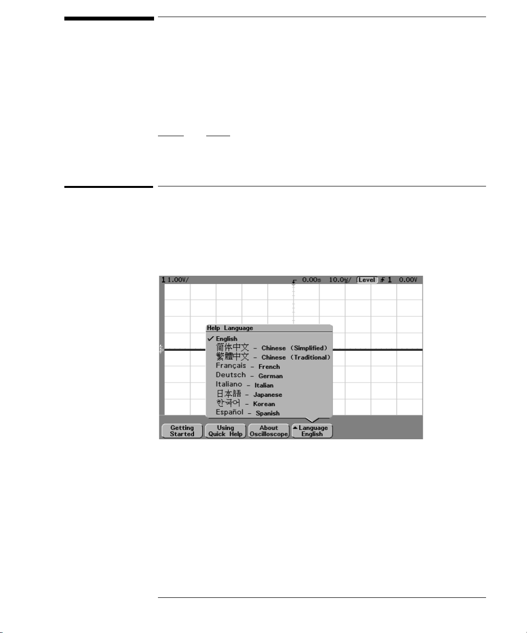
Selecting a language for Quick Help when the oscilloscope starts up
When the oscilloscope first powers up, you can press the Language softkey to
select a language for viewing Quick Help. Successive press the Language sof tk ey
until the desired language in the list selected.
You can also select and load a language later from the Utility Language menu.
1-23
Page 34

Getting Started
Selecting a language for Quick Help after you have been operating the oscilloscope
Selecting a language for Quick Help after you have been
operating the oscilloscope
1Press the Utility key, then press the Language softkey to display the
Language menu.
2Press the
Language softkey until the desired language in the list selected.
If the language you want to load is grayed-out in the list, you will need to load
the language from floppy disk. The language file can be downloaded from
www.agilent.com/find/5462xsw
disk for your instrument
1-24
or call an Agilent center and request a language
Page 35

Getting Started
Loading a language from floppy disk
Loading a language from floppy disk
Language files can be downloaded from www.agilent.com/find/5462xsw or call
an Agilent center and request a language disk for your instrument.
1 Insert the floppy disk with a language file into the floppy disk drive on
the oscilloscope.
2Press the
Language menu.
3Press the
4Press the
oscilloscope.
For more information about loading and deleting languages, refer to the
“Utilities” chapter.
Utility key, then press the Language softkey to display the
Load/Del softkey to select the language to be loaded.
Load Language softkey to load the selected language into the
1-25
Page 36

1-26
Page 37

2
Front-Panel Overview
Page 38

Front-Panel Overview
Before you make measurements using the Agilent 54600-series
Oscilloscopes, you must first set up the instrument using front-panel
controls. Then, make the measurement and read the display results.
These oscilloscopes operate much like an analog scope, but it can do
much more. Spending a few minutes to learn some of this capability will
take you a long way toward more productive troubleshooting. The
“MegaZoom Concepts and Oscilloscope Operation” chapter has more
detail on the things to consider while operating your oscilloscope.
The keys on the front panel bring up softkey menus on the display that
allow access to oscilloscope features. Many softkeys use the Entry
knob to select values.
Throughout this book, the front-panel keys and softkeys are denoted by
a change in the text type. For example, the
panel and the
directly above its corresponding key. Other softkey graphic conventions
used on the oscilloscope and throughout this guide are shown in the
“Getting started using the oscilloscope interface” topic in chapter 1.
Normal softkey is appears at the bottom of the display
Cursors key is on the front
2-2
Page 39

Front-Panel Overview
Important Oscilloscope Considerations
Important Oscilloscope Considerations
Using Single versus Run/Stop
The oscilloscopes have a Single key and a Run/Stop key. When you press Run
(key is illuminated in green), the trigger processing and screen update rate are
optimized over the memory depth. Single acquisitions always use the maximum
memory available—at least twice as much memory as acquisitions captured in
Run mode—and the scope stores at least twice as many samples. At slow sweep
speeds, the oscilloscope operates at a higher sample rate when Single is used
to capture an acquisition, as opposed to running, due to the increased memory
available.
Viewing signal detail with acquire mode
R e m em b e r ho w yo u ha d t o c o ns t a nt l y a d ju s t t he b r i g ht n es s o n o ld a n a lo g s c o pe s
to see a desired level of detail in a signal, or to see the signal at all? With the
Agilent 54600-series oscilloscopes, this is not necessary. The Intensity knob
operates much like the brightness knob on your computer screen, so you should
set it to a level that makes for comfortable viewing, given the room lighting, and
leave it there. Then you can control the detail by selecting an Acquire mode:
Normal, Peak Detect, Average, or Realtime as described in the following
paragraphs.
Normal acquire mode Normal mode is the acquisition mode that you will
probably use for acquiring samples most of the time. It compresses up to 2
million acquisition points per channel into a 1,000-point display record.
The scope’s 200 MSa/s sampling speed specification means that samples are
taken every 5 ns. At the faster sweep speeds, the running display is built from
many individual triggers. If you press the Stop key, and pan and zoom through
the waveform by using the Horizontal and Vertical knobs, only the last trigger’s
acquisition will be displayed.
Whether the oscilloscope is stopped or running, you see more detail as you zoom
in, and l ess a s you zo om out. To keep from l osing detai l as yo u zoom o ut, s witch
to the Peak Detect acquisition mode. Zoom means you expand the waveform
using either the main or delayed sweep window. Panning the waveform means
you use the Horizontal Delay time knob( )to move it horizontally.
2-3
Page 40

Front-Panel Overview
Important Oscilloscope Considerations
Peak Detect acquire mode In Peak Detect acquisition mode, any noise,
peak, or signal wider than 5 ns will be displayed, regardless of sweep speed. In
Normal acquisition mode, at sweep speeds faster than 2 µs/div, you would see
a 5-ns peak, so peak detect has no effect at sweep speeds faster than 2 µs/div.
Using Peak Detect and infinite persistence together is a powerful way to find
spurious signals and glitches.
Average acquire mode Averaging is a way to pull a repetitive signal out of
noise. Averaging works better than either a bandwidth limit or a brightness
control because the bandwidth is not reduced.
The simplest averaging is smoothing (number of averages = 1). For example,
the sample rate at a Time/Div setting of 2 ms/div allows the extra 5-ns samples
to be smoothed together, smoothing the data into one sample, which is then
displayed. As with Peak Detect, smoothing has no effect at less than 2 µs/div.
Smoothing works on a single acquisition (even untriggered and single-shot).
Averaging (number of averages > 1) needs a stable trigger, because in this mode
multiple acquisitions are averaged together. See the “MegaZoom Concepts and
Oscilloscope Operation” chapter for more information about smoothing.
Realtime acquire mode
In Realtime mode, the oscilloscope acquires all of the waveform samples during
one trigger event. To accurately reproduce a sampled waveform, the sample
rate (200 MSa/s for single channel or 100 MSa/s with channel pairs 1 and 2, 3
and 4, or pod 1 and pod 2 running) should be at least four times the highest
frequency component of the waveform. If not, it is possible for the
reconstructed waveform to be distorted or aliased. Aliasing is most commonly
seen as jitter on fast digital edges.
Use Realtime to capture infrequent triggers, unstable triggers, or complex
changing waveforms, such as eye diagrams. Realtime mode is only necessary
at sweep speeds of 200 ns/div and faster.
2-4
Page 41

Front-Panel Overview
Important Oscilloscope Considerations
Auto-Single mode
In Normal trigger mode, the oscilloscope will not trigger or display a waveform
unless a trigger signal is present and trigger conditions are met. In this trigger
mode, each time Single is pressed, the oscilloscope will wait for a valid trigger.
In Auto or Auto Lvl trigger mode, the oscilloscope will generate a trigger for you
if one is not found in the predetermined time from when the trigger system is
armed. To take a single-shot acquisition, if you are not particularly interested
in triggering the acquisition (for example, if you are probing a known signal),
use this auto-trigger mode (auto-signal mode). If a trigger exists, it will be used;
if a trigger does not exist, an untriggered or auto-triggered acquisition will be
taken for later analysis.
Using Vectors (Display menu)
One of the most fundamental choices you must make about your display is
whether to draw vectors (connect the dots) between the samples, or simply let
the samples fill in the waveform. To some degree, this is a matter of personal
preference, but it also depends on the waveform.
• You will probably operate the oscilloscope most often with vectors on. Having
vectors on slows the display of the oscilloscope, thus works better for slower
sweep speeds, peak detect, or average displays, and signals with stable
triggers.
• Having vectors off works better for fast sweep speeds, normal displays, or
unstable triggers. Complex analog signals like video and eye diagrams show
more intensity information with vectors off. Turn vectors off when the
maximum display rate is required, or when highly complex or multi-valued
waveforms are displayed.
Delayed Sweep
Delayed sweep is a simultaneous display of the waveform at two different sweep
speeds. Because of the deep memory in the MegaZoom technology, it is possible
to capture the main display at 1 ms/div, and redisplay the same trigger in the
delayed display at any desired faster time base.
There is no limit imposed on the zoom ratio between the main and delayed
displays. There is, however, a useful limit when the samples are spaced so far
apart that they are of little value. See the “MegaZoom Concepts and
Os ci ll oscop e O per at io n” cha pt er fo r m or e i nf orm at io n abo ut de laye d s wee p a nd
time reference.
2-5
Page 42

Front-Panel Overview
Important Oscilloscope Considerations
Post Acquisition Processing
In addition to changing display parameters after the acquisition, you can do all
of the measurements and math functions after the acquisition. Measurements
and math functions will be recalculated as you pan and zoom and turn channels
on and off. As you zoom in and out on a signal using the horizontal sweep speed
knob and vertical volts/division knob, you affect the resolution of the display.
Because measurements and math functions are performed on displayed data,
you affect the resolution of functions and measurements.
2-6
Page 43

Figure 2-1
Front-Panel Overview
54600-series Oscilloscope1 Front Panels
54600-series Oscilloscope1 Front Panels
Intensity
control
Display
Softkeys
Floppy
disk
Measure
keys
Entry
knob
Autoscale
key
Power
switch
Horizontal
controls
Vertical
inputs/
controls
Waveform
keys
File
keys
Run
controls
Trigger
controls
Utility
key
Probe
comp
output
External
Trigger
input
54621A and 54622A 2-Channel Oscilloscopes Front Panel
2-7
Page 44

Figure 2-2
Front-Panel Overview
54600-series Oscilloscope1 Front Panels
Intensity
control
Display
Softkeys
Floppy
disk
Measure
keys
Entry
knob
Autoscale
key
Power
switch
Horizontal
controls
Vertical
inputs/
controls
Waveform
keys
File
keys
Run
controls
Trigger
controls
Utility
key
Probe
comp
output
54624A 4-Channel Oscilloscope Front Panel
2-8
Page 45

Figure 2-3
Front-Panel Overview
54600-series Oscilloscope1 Front Panels
Intensity
control
Display
Softkeys
Floppy
disk
Measure
keys
Entry
knob
Autoscale
key
Power
switch
Horizontal
controls
Analog Channel
inputs/ controls
Waveform
keys
File
keys
Run
controls
Trigger
controls
Utility
key
Probe
Comp
output
Digital Channel
inputs/ controls
54621D and 54622D Mixed-Signal Oscilloscopes Front Panel
2-9
Page 46

Front-Panel Operation
Thi s ch ap te r p ro vi de s a b ri ef ov er vi ew of in te rpr et in g i nf or ma ti on on th e
display and an introduction to operating the front-panel controls.
Detailed oscilloscope operating instructions are provided in later
chapters.
54621D and 54622D digital channels
Because all of the oscilloscopes in the 54600-series have analog channels, the
analog channel topics in this chapter apply to all instruments. Whenever a topic
discusses the digital channels, that information applies only to the 54621D or 54622D
Mixed-Signal Oscilloscopes.
2-10
Page 47

Front-Panel Overview
Interpreting the display
Interpreting the display
The oscilloscope display contains channel acquisitions, setup information,
measurement results, and softkeys for setting up parameters.
Analog
channels
sensitivity
Analog
channels and
ground levels
Digital
channels
Measurement
line
Softkeys
Digital
channel
activity
Interpreting the display
Trigger point,
time reference
Delay
time
Sweep
speed
Trigger
mode
Trigger
type
Trigger
source
Trigger level
or digital
threshold
Cursor
markers
defining
measurement
Status line The top line of the display contains vertical, horizontal, and trigger
setup information.
Display area The display area contains the waveform acquisitions, channel
identifiers, and analog trigger and ground level indicators.
Measurement line This line normally contains automatic measurement and
cursor results, but can also display advanced trigger setup data and menu
information.
Softkeys The softkeys allow you to set up additional parameters for
front-panel keys.
2-11
Page 48

Front-Panel Overview
To use analog channels to view a signal
To use analog channels to view a signal
• To configure the oscilloscope quickly, press the Autoscale key to display
the connect signal.
• To undo the effects of Autoscale, press the
pressing any other key.
• To set the instrument to the factory-default configuration, press the
Save/Recall key, then press the Default Setup softkey.
Example Connect the oscilloscope probes for channels 1 and 2 to the Probe Comp output
on the front panel of the instrument. Set the instrument to the factory default
configuration by pressing the Save/Recall key, then the Default Setup softkey.
Then press the Autoscale key. You should see a display similar to the following.
Undo Autoscale softkey before
Autoscale with analog channels
2-12
Page 49

Front-Panel Overview
To use digital channels to view a signal
To use digital channels to view a signal
• To configure the instrument quickly, press the Autoscale key.
• To undo the effects of Autoscale, press the
pressing any other key.
• To set the instrument to the factory-default configuration, press the
Save/Recall key, then press the Default Setup softkey.
Example Install probe clips on channels 0 and 1 on the digital probe cable. Connect the
probes for digital channels 0 and 1 to the Probe Comp output on the front panel
of the instrument. Be sure to connect the ground lead. Set the instrument to
the factory default configuration by pressing the Save/Recall key, then the
Default Setup softkey. Then press the Autoscale key. You should see a display
similar to the following.
Undo Autoscale softkey before
Autoscale with digital channels (54621D and 54622D)
2-13
Page 50

Front-Panel Overview
To display signals automatically using Autoscale
To display signals automatically using Autoscale
• To configure the instrument quickly, press the Autoscale key.
Autoscale displays all connected signals that have activity.
To undo the effects of Autoscale, press the Undo Autoscale softkey before
pressing any other key.
How Autoscale Works
Autoscale automatically configures the oscilloscope to best display the input
signal by analyzing any waveforms connected to the external trigger and
channel inputs. Autoscale finds, turns on, and scales any channel with a
repetitive waveform with a frequency of at least 50 Hz, a duty cycle greater than
0.5%, and an amplitude of at least 10 mV peak-to-peak. Any channels that do
not meet these requirements are turned off.
The trigger source is selected by looking for the first valid waveform starting
with external trigger, then continuing with the highest number analog channel
down to the lowest number analog channel, and finally (if applicable) the
highest number digital channel.
During Autoscale, the delay is set to 0.0 seconds, the sweep speed setting is a
function of the input signal (about 2 periods of the triggered signal on the
screen), and the triggering mode is set to edge. Vectors remain in the state they
were before the Autoscale.
Undo Autoscale
Press the Undo Autoscale softkey to return the oscilloscope to the settings that
existed before you pressed the Autoscale key.
This is useful if you have unintentionally pressed the Autoscale key or do not
like the settings Autoscale has selected and want to return to your previous
settings.
2-14
Page 51

Front-Panel Overview
To apply the default factory configuration
To apply the default factory configuration
• To set the instrument to the factory-default configuration, press the
Save/Recall key, then press the Default Setup softkey.
The default configuration returns the oscilloscope to its default settings. This
places the oscilloscope in a known operating condition. The major default
settings are:
Horizontal main mode, 100 us/div scale, 0 s delay, center time reference
Vertical (Analog) Channel 1 on, 5 V/div scale, dc coupling, 0 V position, probe
factor to 1.0 if an AutoProbe probe is not connected to the channel
Trigger Edge trigger, Auto level sweep mode, 0 V level, channel 1 source, dc
coupling, rising edge slope, 60 ns holdoff time
Display Vectors on, 20% grid intensity, infinite persistence off
Other Acquire mode normal, Run/Stop to Run, cursor measurements off
2-15
Page 52

Front-Panel Overview
To adjust analog channel vertical scaling and position
To adjust analog channel vertical scaling and position
This exercise guides you through the vertical keys, knobs, and status line.
1 Center the signal on the display using the position knob.
The position knob ( ) moves the signal vertically; the signal is calibrated.
Notice that as you turn the position knob, a voltage value is displayed for a short
time, indicating how far the ground reference ( )is located from the center
of the screen. Also notice that the ground reference symbol at the left edge of
the display moves with the position knob.
Measurement Hints
If the channel is DC coupled, you can quickly measure the DC component of the
signal by simply noting its distance from the ground symbol.
If the channel is AC coupled, the DC component of the signal is removed, allowing
you to use greater sensitivity to display the AC component of the signal.
2 Change the vertical setup and notice that each change affects the status
line differently. You can quickly determine the vertical setup from the
status line in the display.
• Change the vertical sensitivity with the large volts/division knob in the
Vertical (Analog) section of the front panel and notice that it causes the
status line to change.
• Press the 1 key.
If channel 1 was not turned on, a softkey menu appears on the display, and
the channel turns on (the 1 key will be illuminated).
If channel 1 was already turned on, but another menu was being displayed,
the softkeys will now display the channel 1 menu.
When Vernier is turned off, the volts/div knob can change the channel sensitivity
in a 1-2-5 step sequence. When Vernier is selected, you can change the channel
sensitivity in smaller increments with the volts/division knob. The channel
sensitivity remains fully calibrated when Vernier is on. The sensitivity value is
displayed in the status line at the top of the display.
• To turn the channel off, press the channel 1 key until the key is not
illuminated.
2-16
Page 53

Front-Panel Overview
To set the vertical expand reference for the analog signal
To set the vertical expand reference for the analog signal
When changing the volts/division for analog channels, you can have the signal
expand (or compress) about the signal ground point or about the center
graticule on the display. This works well with two signals displayed, because
you can position and see them both on the screen while you change the
amplitude.
• To expand the signal about the center graticule of the display, press the Utility
key, press the Options softkey, then press the Expand softkey and select
Expand About Center.
With Expand About Center selected, when you turn the volts/division, the
waveform with expand or contract about the center graticule of the display.
• To expand the signal about the position of the channel’s ground, press the
Utility key, press the Options softkey. Then press the Expand softkey and
select Expand About Ground.
With Expand About Ground selected, when you turn the volts/division knob,
the ground level of the waveform remains at the same point on the display,
while the non-ground portions of the waveform expand or contract.
To set analog channel probe attenuation factor
If you have an AutoProbe self-sensing probe (such as the 10074C) connected
to the analog channel, the oscilloscope will automatically configure your probe
to the correct attenuation factor. In the previous figure, the oscilloscope has
sensed an AutoProbe 10:1 probe.
If you do not have an AutoProbe probe connected, you can turn the Entry knob
to set the attenuation factor for the connected probe. The attenuation
factor can be set from 0.1:1 to 1000:1 in a 1-2-5 sequence.
The probe correction factor must be set properly for measurements to be made
correctly.
2-17
Page 54

Front-Panel Overview
To display and rearrange the digital channels
To display and rearrange the digital channels
1Press the D15 Thru D8 key or D7 Thru D0 key to turn the display of the digital
channels on or off.
The digital channels are displayed when these keys are illuminated.
2 Turn the Digital Channel Select knob to select a single digital channel.
The selected channel number is highlighted on the left side of the display.
3 Turn the Digital position knob ( ) to reposition the selected channel
on the display.
If two or more ch annels are disp layed a t the sa me pos iti on, a po p up will appear
showing the overlaid channels. Continue turning the Channel Select knob until
the desired channel within the pop up is selected.
2-18
Page 55

Front-Panel Overview
To operate the time base controls
To operate the time base controls
The following exercise guides you through the time base keys, knobs, and status
line.
• Turn the Horizontal sweep speed (time/division) knob and notice the
change it makes to the status line.
The sweep speed knob changes the sweep speed from 5 ns/div to 50 s/div in a
1-2-5 step sequence, and the value of the sweep speed is displayed in the status
line at the top of the display.
•Press the Main/Delayed, then press the Vernier softkey.
The Vernier softkey allows you to change the sweep speed in smaller increments
with the time/div knob. These smaller increments are calibrated, which result
in accurate measurements, even with the vernier turned on.
• Turn the delay time knob ( ) and notice that its value is displayed in
the status line.
The delay knob moves the main sweep horizontally, and it pauses at 0.00 s,
mimicking a mechanical detent. At the top of the graticule is a solid triangle
(
▼) symbol and an open triangle (∇) s y mb o l. T h e ▼ symbol indicates the trigger
point and it moves with the Delay time knob. The ∇ symbol indicates the time
reference point. If the Ti me Re f so f t k e y i s s e t t o Left, the ∇ i s lo c a t ed o ne g r a t ic u l e
in from the left side of the display. If the Time Ref softkey is set to Center, the
is located at the center of the display. If the Time Ref softkey is set to Right, the
∇ i s l ocate d o ne g ra ti cule in fr om th e r igh t s id e o f t he di spl ay. The de la y nu mb er
tells you how far the time reference point ∇ is located from the trigger point
All events displayed left of the trigger point
occurred, and these events are called pre-trigger information. You will find this
feature very useful because you can now see the events that led up to the trigger
point. Everything to the right of the trigger point
information. The amount of delay range (pre-trigger and post-trigger
information) available depends on the sweep speed selected.
▼ happened before the trigger
▼ is called post-trigger
∇
▼.
2-19
Page 56

Front-Panel Overview
To start and stop an acquisition
To start and stop an acquisition
•When the Run/Stop key is illuminated in green, the oscilloscope is in
continuous running mode.
You are viewing multiple acquisitions of the same signal similar to the way an
analog oscilloscope displays waveforms.
•When the Run/Stop key is illuminated in red, the oscilloscope is stopped.
“Stop” is displayed in the trigger mode position in status line at the top of the
display. You may now pan and zoom the stored waveform by turning the
Horizontal and Vertical knobs.
The stopped display may contain several triggers worth of information, but only
the last trigger acquisition is available for pan and zoom. To ensure the display
does not change, use the Single key to be sure you have acquired only one
trigger.
To make a single acquisition
The Single run control key lets you view single-shot events without subsequent
waveform data overwriting the display. Use Single when you want maximum
memory depth for pan and zoom.
1 First set trigger Mode/Coupling Mode softkey to Normal.
This keeps the oscilloscope from autotriggering immediately.
2 If you are using the analog channels to capture the event, turn the
Trigger Level knob to the trigger threshold where you think the trigger
should work.
3 To begin a single acquisition, press the
When you press Single, the display is cleared, the trigger circuitry is armed, the
Single key is illuminated, and the oscilloscope will wait until a trigger condition
occurs before it displays a waveform.
When the oscilloscope triggers, the single acquisition is displayed and the
oscilloscope is stopped (Run/Stop key is illuminated in red). Press Single again
to acquire another waveform.
Single key.
2-20
Page 57

Front-Panel Overview
To use delayed sweep
To use delayed sweep
Delayed sweep is an expanded version of main sweep. When Delayed mode is
selected, the display divides in half and the delayed sweep icon displays in
the middle of the line at the top of the display. The top half displays the main
sweep and the bottom half displays the delayed sweep.
The following steps show you how to use delayed sweep. Notice that the steps
are very similar to operating the delayed sweep in analog oscilloscopes.
1 Connect a signal to the oscilloscope and obtain a stable display.
2Press
3Press the
Main/Delayed.
Delayed softkey.
To change the sweep speed for the delayed sweep window, turn the sweep speed
knob. As you turn the knob, the sweep speed is highlighted in the status line
above the waveform display area.
The area of the main display that is expanded is intensified and marked on each
en d w it h a v er ti cal ma rker. The se mark er s show wh at po rt io n o f t he m ai n s we ep
is e xp ande d i n t he lo we r h alf . T he Ho ri zo nt al k no bs co ntro l t he s ize an d p osi ti on
of the delayed sweep. The delay value is momentarily displayed in the
upper-right portion of the display when the delay time ( ) knob is turned.
Delayed sweep is a magnified portion of the main sweep. You can use delayed
sweep to locate and horizontally expand part of the main sweep for a more
detailed (higher-resolution) analysis of signals.
The point about which the delayed sweep window is expanded is referenced to
the delay time and is dependent on the time reference setting:
• When Time Ref is set to Left, the delayed sweep expands to the right starting
from the delay time setting (one graticule from the left side of the display
when delay time = 0).
• When Time Ref is set to Center, the delayed sweep expands equally left and
right) from the delay time setting (center of the display when delay time = 0).
• When Time Ref is set to Right, the delayed sweep expands to the left starting
from the delay time setting (one graticule from the right side of the display
when delay time = 0).
To ch ange th e sw eep spe ed for the main s weep wi ndow, pr ess the Main softkey,
then turn the sweep speed knob.
2-21
Page 58

Front-Panel Overview
To make cursor measurements
To make cursor measurements
You can use the cursors to make custom voltage or time measurements on scope
signals, and timing measurements on digital channels.
1 Connect a signal to the oscilloscope and obtain a stable display.
2Press the
Mode Set the cursors results to measure voltage and time (Normal), or display
the binary or hexadecimal logic value of the displayed waveforms.
Source selects a channel or math function for the cursor measurements.
X Y Select either the X cursors or the Y cursors for adjustment with the Entry
knob.
X1 and X2 adjust horizontally and normally measure time.
Y1 and Y2 adjust vertically and normally measure voltage.
X1 X2 and Y1 Y2 move the cursors together when turning the Entry knob.
For more information about using cursors for measurements, refer to the
“Making Measurements” chapter.
Cursors key. View the cursor functions in the softkey menu:
2-22
Page 59

Front-Panel Overview
To make automatic measurements
To make automatic measurements
You can use automatic measurements on any channel source or any running
math function. Cursors are turned on to focus on the most recently selected
measurement (right-most on the measurement line above the softkeys on the
display).
1Press the Quick Meas key to display the automatic measurement menu.
2Press the
on which the quick measurements will be made.
Only channels or math functions that are displayed are available for
measurements. If a portion of the waveform required for a measurement is not
displayed or does not display enough resolution to make the measurement, the
result will be displayed with a message such as greater than a value, less than
a value, not enough edges, not enough amplitude, incomplete, or waveform is
clipped to indicate that the measurement may not be reliable.
3Press the Clear Meas softkey to stop making measurements and to erase
the measurement results from the measurement line above the
softkeys.
When Quick Meas is pressed again, the default measurements on an analog
channel will be will be Frequency and Peak-Peak.
4 Choose what measurements you want on that source by pressing the
softkey.
Source softkey to select the channel or running math function
5To turn off
Quick Meas, press the Quick Meas key again until it is not
illuminated.
For detailed information about making automatic measurements, refer to the
“Making Measurements” chapter.
2-23
Page 60

Front-Panel Overview
To modify the display grid
To modify the display grid
1Press the Display key.
2 Turn the Entry knob to change the intensity of the displayed grid. The
intensity level is shown in the
Grid softkey and is adjustable from 0 to
100%.
Each major division in the grid (also know as graticule) corresponds to the
sweep speed time shown in the status line on the top of the display.
• To change waveform intensity, turn the INTENSITY knob on the
lower-left corner of the front panel.
To print the display
You can print the complete display, including the status line and softkeys, to a
parallel printer or to the floppy disk by pressing the Quick Print key. You can
stop printing by pressing the Cancel Print softkey.
To set up your printer, press the Utility key, then press the Print Confg softkey.
For more information on printing and floppy disk operation, refer to the
“Utilities” chapter.
2-24
Page 61

3
Triggering the Oscilloscope
Page 62

Triggering the Oscilloscope
The Agilent 54600-series Oscilloscopes provide a full set of features to
help automate your measurement tasks, including MegaZoom
technology to help you capture and examine the stored waveforms of
interest, even untriggered waveforms. With these oscilloscopes you can:
• modify the way the oscilloscope acquires data.
• set up simple or complex trigger conditions, as needed, to capture
only the sequence of events you want to examine.
The oscilloscopes all have common triggering functionality:
• Trigger modes (Auto Level, Auto, Normal)
• Trigger types (slope/edge, pulse width, pattern, duration, sequence,
2
C, and TV triggering)
I
• Mode/Coupling (including high frequency and noise rejection)
• Holdoff and Trigger Level
3-2
Page 63

Selecting Trigger Modes and Conditions
The trigger mode affects the way in which the oscilloscope searches for
the trigger. The figure below shows the conceptual representation of
acquisition memory. Think of the trigger event as dividing acquisition
memory into a pre-trigger and post-trigger buffer. The position of the
trigger event in acquisition memory is defined by the time reference
point and the delay setting.
Trigger Event
Pre-Trigger Buffer
Acquisition Memory
Acquisition Memory
Post-Trigger Buffer
To select the Mode and Coupling menu
•Press the Mode/Coupling key in the Trigger section of the front panel.
3-3
Page 64

Triggering the Oscilloscope
To select a trigger mode: Auto Level, Auto, Normal
To select a trigger mode: Auto Level, Auto, Normal
1Press the Mode/Coupling key.
2Press the
• Normal mode displays a waveform the trigger conditions are met, otherwise
the oscilloscope does not trigger and the display is not updated.
• Auto mode is the same as Normal mode, except it forces the oscilloscope to
trigger if the trigger conditions are not met.
• Auto Level mode works only when edge triggering on analog channels or
external trigger. The oscilloscope first tries to Normal trigger. If no trigger
is found, it searches for a signal at least 10% of full scale on the trigger source
and sets the trigger level to the 50% amplitude point. If there is still no signal
present, the oscilloscope auto triggers. This mode is useful when moving a
probe from point to point on a circuit board.
Auto Level and Auto modes
Us e t he au to tr igge r m od es fo r sig na ls ot he r t han lo w- rep et iti ve -r at e sig na ls . To
display a dc signal, you must use one of these two auto trigger modes since there
are no edges on which to trigger.
Auto Level mode is the same as Auto mode with an automatic trigger level
adjustment. The oscilloscope looks at the level on the signals, and if the trigger
level is out-of-range with respect to the signal, the scope adjusts the trigger
level back to the middle of the signal.
When you select Run, the oscilloscope operates by first filling the pre-trigger
buffer. It continues to flow data through this buffer while it searches for the
trigger. While searching for the trigger, the oscilloscope overflows the
pre-trigger buffer; the first data put into the buffer is the first pushed out
(FIFO). When a trigger is found, the pre-trigger buffer will contain the events
that occurred just before the trigger. If no trigger is found, the oscilloscope
generates a trigger and displays the data as though a trigger had occurred.
When you select Single, the oscilloscope will fill pre-trigger buffer memory, and
continue flowing data through the pre-trigger buffer until the auto trigger
overrides the searching and commands a trigger. At the end of the trace, the
scope will stop and display the results.
Mode softkey, then select Auto Level, Auto, or Normal trigger.
3-4
Page 65

Triggering the Oscilloscope
To select a trigger mode: Auto Level, Auto, Normal
Normal mode
Use Normal trigger mode for low repetitive-rate signals. In this mode, the
oscilloscope has the same behavior whether the acquisition was initiated by
pressing Run/Stop or Single.
When the trigger event is found, the oscilloscope will fill the post-trigger buffer
and display the acquisition memory. If the acquisition was initiated by Run/Stop,
the process repeats. The waveform data will be scrolled onto the display as it
is being acquired.
In Normal mode the oscilloscope must fill the pre-trigger buffer with data before
it will begin searching for a trigger event. The trigger mode indicator on the
status line flashes to indicate the oscilloscope is filling the pre-trigger buffer.
While searching for the trigger, the oscilloscope overflows the pre-trigger buffer;
the first data put into the buffer is the first pushed out (FIFO).
In either Auto or Normal mode, the trigger may be missed completely under
certain conditions. This is because the oscilloscope will not recognize a trigger
event until the pre-trigger buffer is full. Suppose you set the Time/Div knob to
a slow sweep speed, such as 500 ms/div. If the trigger condition occurs before
the oscilloscope has filled the pre-trigger buffer, the trigger will not be found.
If you use Normal mode and wait for the trigger condition indicator to flash
before causing the action in the circuit, the oscilloscope will always find the
trigger condition correctly.
Some measurements you want to make will require you to take some action in
the circuit under test to cause the trigger event. Usually, these are single-shot
acquisitions, where you will use the Single key.
3-5
Page 66

Triggering the Oscilloscope
To select trigger Coupling
To select trigger Coupling
1Press the Mode/Coupling key.
2Press the
• DC coupling allows dc and ac signals into the trigger path.
• AC coupling places a 3.5 Hz high-pass filter in the trigger path removing any
DC offset voltage from the trigger waveform. Use AC coupling to get a stable
edge trigger when your waveform has a large DC offset.
• LF (low frequency) Reject coupling places a 50-kHz high-pass filter in series
with the trigger waveform. Low frequency reject removes any unwanted low
frequency components from a trigger waveform, such as power line
frequencies, that can interfere with proper triggering. Use this coupling to
get a stable edge trigger when your waveform has low frequency noise.
• TV coupling is normally grayed-out, but is automatically selected when TV
trigger is enabled in the Trigger More menu.
Coupling softkey, then select DC, AC, or LF Reject coupling.
To select Noise Reject and HF Reject
1Press the Mode/Coupling key.
2Press the
softkey to select high frequency reject.
• Noise Rej adds additional hysteresis to the trigger circuitry. When noise reject
is on, the trigger circuitry is less sensitive to noise but may require a greater
amplitude waveform to trigger the oscilloscope.
• HF Reject adds a 50 kHz low-pass filter in the trigger path to remove high
frequency components from the trigger waveform. You can use HF Reject to
remove high-frequency noise, such as AM or FM broadcast stations, from the
trigger path.
3-6
Noise Rej softkey to select noise reject or press the HF Reject
Page 67

Triggering the Oscilloscope
To set holdoff
To set holdoff
1Press the Mode/Coupling key.
2 Turn the Entry knob to increase or decrease the trigger holdoff
time shown in the
Ho ld of f set s t he a mo un t o f t im e th at th e o sc il lo sc op e w ai ts be fore r e- arm in g t he
trigger circuitry. Use Holdoff to stabilize the display of complex waveforms.
To get a stable trigger on the pulse burst shown below, set the holdoff time to
be >200 ns but <600 ns.
Holdoff softkey.
+ROGRII
QV QV
By setting the Holdoff, you can synchronize triggers. The oscilloscope will
trigger on one edge of the waveform, and ignore further edges until the holdoff
time expires. The oscilloscope will then re-arm the trigger circuit to search for
the next edge trigger. This allows the oscilloscope to trigger on a repeating
pattern in a waveform.
6FRSHWULJJHUVKHUH
3-7
Page 68

Triggering the Oscilloscope
To set holdoff
Holdoff Operating Hints
Holdoff keeps a trigger from occurring until after a certain amount of time has passed
since the last trigger. This feature is valuable when a waveform crosses the trigger
level multiple times during one period of the waveform.
Without holdoff, the scope could trigger on each of the crossings, producing a
confusing waveform. With holdoff set correctly, the scope always triggers on the
same crossing. The correct holdoff setting is typically slightly less than one period.
Set the holdoff to this time to generate a unique trigger point. This action works even
though many waveform periods pass between triggers, because the holdoff circuit
operates on the input signal continuously.
Changing the time base settings does not affect the holdoff number. In contrast, the
holdoff in analog oscilloscopes is a function of the time base setting, making it
necessary to re-adjust the holdoff each time you change the time base setting.
With Agilent’s MegaZoom technology, you can press Stop, then pan and zoom
through the data to find where it repeats. Measure this time using the cursors, then
set holdoff to this number.
3-8
Page 69

Trigger Types
The oscilloscope allows you to synchronize the display to the actions of
the circuit under test by defining a trigger condition. The triggering
modes include Auto Level, Auto, and Normal. Triggering types include
edge, pulse width, pattern, duration, sequence, I
can use any input channel, line, or the Ext Trigger BNC for the source.
MegaZoom Technology Simplifies Triggering
With the built-in MegaZoom technology, you can simply Autoscale the waveforms,
then stop the scope to capture a waveform. You can then pan and zoom through the
data using the Horizontal and Vertical knobs to find a stable trigger point. Autoscale
often produces a triggered display.
These trigger types are available:
• Edge trigger
• Pulse Width trigger
• Pattern trigger
• Duration trigger
2
•I
C (Inter-IC bus) trigger
• Sequence trigger
2
C, and TV trigger. You
Changes to the trigger specification are applied when you make them. If the
oscilloscope is stopped when you change a trigger specification, the scope will
use the new specification when you press Run/Stop or Single. If the oscilloscope
is running when you change a triggering specification, it uses the new trigger
definition when it starts the next acquisition. You select the trigger type by
pressing the key associated with the desired trigger type.
3-9
Page 70

Triggering the Oscilloscope
To use edge triggering
To use edge triggering
The Edge trigger type identifies a trigger by looking for a specified slope and
voltage level on a waveform. You can define the trigger source and rising or
falling edge in this menu. The trigger type, source, and level is displayed in the
upper-right corner of the display.
1Press the Edge key in the Trigger section of the front panel to display
the edge trigger menu.
Slope
Trigger
source
Trigger level
or threshold
Slope
Analog channel
source
Digital channel
source
External or Line
source
2 Press the slope softkey ( ) and select either rising edge or falling
edge. This determines whether the trigger will occur on the rising edge
or the falling edge of the input signal.
Slope Selects rising edge ( ) or falling edge ( ) for the selected trigger
source. The selected slope is displayed in the upper-right corner of the display.
3 Select 1, 2, Ext, or Line as the trigger source.
The trigger source can also be set to channel 3 and 4 on the 4-channel
oscilloscope, or can be set to digital channels D15 through D0 on the
mixed-signal oscilloscope. You can choose a channel that is turned off as the
source for the edge trigger. The selected trigger source is displayed in the
upper-right corner of the display:
1 through 4 = analog channels
D15 through D0 = digital channels
E = External trigger
L = Line trigger
3-10
Page 71

Triggering the Oscilloscope
To use edge triggering
Analog source Press the analog channel source softkey to select an analog
source. Adjust the trigger level for the selected analog channel by turning the
Trigger Level knob. The position of the trigger level for the analog channel is
indicated by the trigger level icon (if the analog channel is on) at the far left
T
side of the display when DC coupling is selected. The value of the analog
channel trigger level is displayed in the upper-right corner of the display.
Digital source (mixed-signal oscilloscope) Press the digital source
softkey or turn the Entry knob to select a digital channel (D15-D0) as the trigger
source. Select Threshold in the D7 Thru D0 or D15 Thru D8 menu to set the
threshold level (TTL, CMOS, ECL, or user defined) for the selected digital
channel group. The threshold value is displayed in the upper-right corner of the
display.
External/Line source Ext (external trigger) and Line (triggers off the power
line frequency) trigger share the same softkey on the display. Toggle the softkey
to select the source you want.
The external trigger input is on the front panel of the 2-channel oscilloscope
and on the rear-panel of 4-channel and mixed-signal oscilloscope. You can
connect the trigger output of other instruments to this external trigger input,
or use an oscilloscope probe, such as the 10074C.
Adjust the external trigger level for the selected analog channel by turning the
Trigger Level knob. The trigger level for Line is not adjustable.
3-11
Page 72

Triggering the Oscilloscope
To use pulse width triggering
To use pulse width triggering
Pulse Width triggering sets the oscilloscope to trigger on a positive pulse or a
negative pulse of a specified width. If you want to trigger on a specific timeout
value, use Duration trigger in the trigger More menu.
1Press the Pulse Width key in the Trigger section of the front panel to
display the pulse width trigger menu.
Trigger level
or threshold
Source
2Press the
Trigger
source
Pulse
polarity
Polarity
Qualifier Qualifier time set
Source softkey (or rotate the Entry knob on mixed-signal
oscilloscopes) to select a channel source for the trigger.
The source can be any analog or digital channel available on your oscilloscope.
External trigger may also be specified as a source when using the 2-channel and
4-channel oscilloscopes.
Adjust the trigger level for the selected analog channel source by turning the
Trigger Level knob. The position of the trigger level for the analog channel is
indicated by the trigger level icon (if the analog channel is on) at the far left
side of the display when DC coupling is selected. Set the threshold for the
selected digital channel group using the D7 Thru D0 or D15 Thru D8 Threshold
softkey. The value of the trigger level or digital threshold is displayed in the
upper-right corner of the display.
T
3-12
Page 73

Triggering the Oscilloscope
To use pulse width triggering
3 Press the pulse polarity softkey to select positive ( )or negative ( )
polarity for the pulse width you want to capture.
The selected pulse polarity is displayed in the upper-right corner of the display.
A positive pulse is higher than the current trigger level or threshold and a
negative pulse is lower than the current trigger level or threshold.
When triggering on a positive pulse, the trigger will occur on the high to low
transition of the pulse if the qualifying condition is true. When triggering on a
negative pulse, the trigger will occur on the low to high transition of the pulse
if the qualifying condition is true.
4 Press the qualifier softkey (< > ><) to select the time qualifier.
The Qualifier softkey can set the oscilloscope to trigger on a pulse width that is:
• less than a time value (<).
For example, for a positive pulse, if you set t<10 ns:
10 ns
• greater than a time value (>).
For example, for a positive pulse, if you set t>10 ns:
10 ns
Trigger
10 ns10 ns
• within a range of time values (><).
For example, for a positive pulse, if you set t>10 ns and t<15 ns:
10 ns
15 ns
12 ns
Trigger
Trigger
3-13
Page 74

Triggering the Oscilloscope
To use pulse width triggering
5 Select the qualifier time set softkey (< or >), then rotate the Entry knob
to set the pulse width qualifier time.
The qualifiers can be set from 10 ns to 10 s.
< qualifier time set softkey
• When the less than (<) qualifier is selected, the Entry knob sets the
oscilloscope to trigger on a pulse width less than the time value displayed
on the softkey.
• When the time range (><) qualifier is selected, the Entry knob sets the
upper time range value.
> qualifier time set softkey
• When the greater than (>) qualifier is selected, the Entry knob sets the
oscilloscope to trigger on a pulse width greater than the time value
displayed on the softkey.
• When the time range (><) qualifier is selected, the Entry knob sets the
lower time range value.
3-14
Page 75

Triggering the Oscilloscope
To use pattern triggering
To use pattern triggering
The Pattern trigger identifies a trigger condition by looking for a specified
pattern. This pattern is a logical AND combination of the channels. Each
channel can have a value of high (H), low (L), don’t care (X), or a rising or falling
edge.
1Press the Pattern key in the Trigger section of the front panel to display
the pattern trigger menu.
Pattern
trigger
Selected
channel
Trigger level
or threshold
Channel
select
Logic Low
Logic High Don’t care Rising or
falling edge
2 For each analog or digital channel you want to include in the desired
pattern, press the
This is the channel source for the H, L, X, or edge condition. As you press the
Channel softkey (or rotate the Entry knob on mixed-signal oscilloscopes), the
channel you select is highlighted in the Pattern = line directly above the
softkeys and in the upper-right corner of the display next to "Pat". External
trigger may also be specified as a channel in the pattern when using the
2-channel and 4-channel oscilloscopes.
Adjust the trigger level for the selected analog channel by turning the Trigger
Level knob. The position of the trigger level for the analog channel is indicated
by the trigger level icon at the far left side of the display when DC coupling
is selected. Set the threshold for the selected digital channel group using the
D7 Thru D0 or D15 Thru D8 Threshold softkey. The value of the trigger level or
digital threshold is displayed in the upper-right corner of the display.
Channel softkey to select the channel.
T
3-15
Page 76

Triggering the Oscilloscope
To use pattern triggering
3 For each channel you select, press one of the condition softkeys to set
the condition for that channel in the pattern.
• H sets the pattern to high on the selected channel. A high is a voltage level
that is greater than the channel's trigger level or threshold level.
• L sets the pattern to low on the selected channel. A low is a voltage level that
is less than the channel's trigger level or threshold level.
• X sets the pattern to don't care on the selected channel. Any channel set to
don't care is ignored and is not used as part of the pattern. If all channels in
the pattern are set to don't care, the oscilloscope will not trigger.
• The rising edge ( ) or falling edge ( ) falling edge softkey sets the pattern
to an edge on the selected channel. Only one rising or falling edge can be
specified in the pattern. When an edge is specified, the oscilloscope will
trigger at the edge specified if the pattern set for the other channels is true.
If no edge is specified, the oscilloscope will trigger on the last edge that makes
the pattern true.
Specifying an Edge in a Pattern
You are allowed to specify only one rising or falling edge term in the pattern. If
you define an edge term, then select a different channel in the pattern and define
another edge term, the previous edge definition is changed to a don’t care.
3-16
Page 77

Triggering the Oscilloscope
To use duration triggering
To use duration triggering
Duration trigger lets you define a pattern, then trigger on a specified time
duration of this logical AND combination of the channels.
1Press the More key in the Trigger section of the front panel, press the
Duration softkey, then press the Settings softkey to display the duration
trigger menu.
Trigger level
or threshold
Return to
previous menu
Channel
select
Logic level
Qualifier
Duration
trigger
Qualifier time set
Selected
channel
2 For each analog or digital channel you want to include in the desired
pattern, press the
Thi s is th e channel source for the H, L, or X condi tio n. As you press the Channel
softkey (or rotate the Entry knob on mixed-signal oscilloscopes), the channel
you select is highlighted in the Pattern = line d irec tly abo ve t he softkeys and
in the upper-right corner of the display next to "Dur". External trigger may also
be specified as a channel in the pattern when using the 2-channel and 4-channel
oscilloscopes.
Adjust the trigger level for the selected analog channel by turning the Trigger
Level knob. The position of the trigger level for the analog channel is indicated
by the trigger level icon at the far left side of the display when DC coupling
is selected. Set the threshold for the selected digital channel group using the
D7 Thru D0 or D15 Thru D8 Threshold softkey. The value of the trigger level or
digital threshold is displayed in the upper-right corner of the display.
Channel softkey to select the channel.
T
3-17
Page 78

Triggering the Oscilloscope
To use duration triggering
3 For each channel you select, press the logic level softkey to set the
condition for that channel in the pattern.
• H sets the pattern to high on the selected channel. A high is a voltage level
that is greater than the channel's trigger level or threshold level.
• L sets the pattern to low on the selected channel. A low is a voltage level that
is less than the channel's trigger level or threshold level.
• X sets the pattern to don't care on the selected channel. Any channel set to
don't care is ignored and is not used as part of the pattern. If all channels in
the pattern are set to don't care, the oscilloscope will not trigger.
4Press the Qualifier softkey to set the time duration qualifier for the
pattern.
The time qualifier can set the oscilloscope to trigger on a channel pattern whose
time duration is:
• less than a time value (<)
• greater than a time value (>)
• greater than a time value, but with timeout (Timeout). A trigger will be forced
at the timeout value.
• within a range of time values (><)
• outside a range of time values (<>)
The time values for the selected qualifier are set using the qualifier time set
softkeys (< and >) and the Entry knob.
3-18
Page 79

Triggering the Oscilloscope
To use duration triggering
5 Select a qualifier time set softkey (< or >), then rotate the Entry knob to
set the duration qualifier time.
< qualifier time set softkey
• When the less than (<) qualifier is selected, the Entry knob sets the
oscilloscope to trigger on a pattern duration less than the time value
displayed on the softkey.
• When the within time range (><) qualifier is selected, the Entry knob sets
the upper time range value.
• When the out of time range (<>) qualifier is selected, the Entry knob sets
the lower time range value.
> qualifier time set softkey
• When the greater than (>) qualifier is selected, the Entry knob sets the
oscilloscope to trigger on a pattern duration greater than the time value
displayed on the softkey.
• When the within time range (><) qualifier is selected, the Entry knob sets
the lower time range value.
• When the out of time range (<>) qualifier is selected, the Entry knob sets
the upper time range value.
• When Timeout qualifier is selected, the Entry knob sets the timeout value.
When the duration trigger occurs
The timer starts on the last edge that makes the pattern (logical AND) true. The
trigger will occur on the first edge that makes the pattern false if the time qualifier
criteria of the pattern has been met or when the timeout value is reached.
3-19
Page 80

Triggering the Oscilloscope
To use I2C triggering
To use I2C triggering
An I2C (Inter-IC bus) trigger setup consists of connecting the oscilloscope to
the serial data (SDA) line and the serial clock (SCL) line, then triggering on a
stop/start condition or triggering on a read/write frame with a specific device
address and data value.
1Press the More key in the Trigger section of the front panel, press the I
softkey, then press the Settings softkey to display the I2C trigger menu.
2
C
Clock
channel
Data
channel
Trigger on:
condition
Currently selected Clock
I2C trigger
Address
or Data channel
Data
value
Trigger level
or threshold
Return to
previous menu
2 Connect an oscilloscope channel to the serial clock (SCL) line in the
circuit under test, then set the
As you press the Clock softkey (or rotate the Entry knob on mixed-signal
oscilloscopes), the channel you select is shown in the upper-right corner of the
display next to "I
and fast-mode (400 kbit/s) systems.
Adjust the trigger level for the selected analog channel by turning the Trigger
Level knob. For the mixed-signal oscilloscope, select Threshold in the D7 Thru
D0 or D15 Thru D8 menu to set the level f or di gita l chan nels a ssign ed to the clock
and data lines. The value of the trigger level or digital threshold is displayed in
the upper-right corner of the display.
2
C". The clock rate is compatible with standard (100 kbit/s)
Clock channel softkey to that channel.
3-20
Page 81

Triggering the Oscilloscope
To use I2C triggering
3 Connect an oscilloscope channel to the serial data (SDA) line in the
circuit under test, then set the
As you press the Data softkey (or rotate the Entry knob on mixed-signal
oscilloscopes), the channel you select is shown in the upper-right corner of the
display next to "I
Adjust the trigger level for the selected analog channel by turning the Trigger
Level knob. For the mixed-signal oscilloscope, select Threshold in the D7 Thru
D0 or D15 Thru D8 menu to set the level f or di gita l chan nels a ssign ed to the clock
and data lines. The value of the trigger level or digital threshold is displayed in
the upper-right corner of the display.
Data needs to be stable during the whole high clock cycle or it will be interpreted
as a start or stop condition (data transitioning while the clock is high).
2
C".
Data channel softkey to that channel.
4Press the Tr i gge r : softkey to select one of the following I2C trigger
conditions:
Start Condition: the oscilloscope triggers when data (SDA) transitions from high
to low while the clock (SCL) is high. For triggering purposes (including frame
triggers), a restart is treated as a start condition.
Stop Condition: the oscilloscope triggers when data (SDA) transitions from low
to high while the clock (SCL) is high.
SDA
SCL
Start
Condition
Address
R/W
ACK
DATA
Trigger
point
ACK
Stop
Condition
Frame (Start: Addr: Read: Ack: Data) or
Frame (Start: Addr: Write: Ack: Data): the oscilloscope triggers on a read or write
frame on the 17th clock edge if all bits in the pattern match.
Frame (Start: ~[Addr: Read: Ack: Data]) or
Frame (Start: ~[Addr: Write: Ack: Data]): same as the read or write frame above,
except the oscilloscope triggers on the 17th clock edge if any bits in the pattern
do not match.
3-21
Page 82

Triggering the Oscilloscope
To use I2C triggering
5 If you have set the oscilloscope to trigger on a read or write frame
condition, press the
Address softkey and turn the Entry knob to select
the 7-bit device address.
You can select from an address range of 0x00 to 0x7F (hexadecimal).
When triggering on a read/write frame, the oscilloscope will trigger after the
start, address, read/write, acknowledge, and data events occur.
If don’t care (0xXX) is selected for the address, the address will be ignored. The
trigger will always occur on the 17th clock regardless of whether or not don’t
care has been selected.
6 If you have set the oscilloscope to trigger on a read or write frame
condition, press the
Data value softkey and turn the Entry knob to select
the 8-bit data pattern on which to trigger.
You can select a data value in the range of 0x00 to 0xFF (hexadecimal).
The oscilloscope will trigger after the start, address, read/write, acknowledge,
and data events occur.
If don’t care (0xXX) is selected for data, the data will be ignored. The trigger
will always occur on the 17th clock regardless of whether or not don’t care has
been selected.
3-22
Page 83

Triggering the Oscilloscope
To use sequence triggering
To use sequence triggering
Sequence trigger allows you to trigger the oscilloscope after finding a sequence
of events. Defining a sequence trigger requires three steps:
a Define an event to find before you trigger on the next event.
The “find” event can be a pattern, an edge from a single channel, or the
combination of a pattern and a channel edge.
b Define the trigger event.
The “trigger on” event can be a pattern, an edge from a single channel, the
combination of a pattern and a channel edge, or the nth occurrence of an
edge from a single channel.
c Set an optional reset event.
If you choose to define a “reset” event, the event can be a pattern, an edge
from a single channel, the combination of a pattern and a channel edge, or a
timeout value. If no reset is defined, it will reset on the Find condition.
Start
Find:?
No
Sequence Trigger Flowchart
Yes
No
Trigger on:?
No
Reset on:?
Yes
Yes
•Press the More key in the Trigger section of the front panel, press the
Sequence softkey, then press the Settings softkey to display the Sequence
trigger menu.
Scope
triggers
Trigger
holdoff
3-23
Page 84

Triggering the Oscilloscope
To use sequence triggering
Sequence stage
definitions
Term definitions
Channel
select
Stage
select
Find, Trigger on,
or Reset condition
Sequence
trigger
Select
term
Selected
channel
Define
term
Trigger level
or threshold
Return to
previous menu
As you set stage, term, and channel definitions for the sequence trigger, these
settings will be shown in the waveform area of the display.
3-24
Page 85

Triggering the Oscilloscope
To use sequence triggering
Define the Find: stage
1Press the Stage softkey and select Find:.
Find: is the first stage in the trigger sequence. When you select the Stage Find
softkey, the next softkey to the right will display Find: and give you a list of the
terms you can define for the Find stage. The Find stage can be set to one of the
following conditions:
Pattern 1 Entered – A pattern is entered on the last edge that makes the
pattern true (logical AND).
Pattern 1 Exited – A pattern is exited on the first edge that makes the pattern
false (logical NAND).
Edge 1
Pattern 1 and Edge 1
2Press the Find: softkey and select the Find stage condition.
3 To define the term(s) used in the Find stage, press the
select the pattern and/or edge term displayed in the
4 If you select a pattern term, each channel in the pattern must be set to
H (high), L (low), or X (don’t care).
a
aPress the Channel softkey (or rotate the Entry knob on mixed-signal
oscilloscopes) to select the channel.
As you select a channel, the channel is highlighted in the selected pattern
list shown in the waveform area and is also shown in the upper-right corner
of the display next to "Seq"
bPress the L H X softkey to set a level for the channel.
• H sets the pattern to high on the selected channel. A high is a voltage level
that is greater than the channel's trigger level or threshold level.
• L sets the pattern to low on the selected channel. A low is a voltage level
that is less than the channel's trigger level or threshold level.
• X sets the pattern to don't care on the selected channel. Any channel set
to don't care is ignored and is not used as part of the pattern. If all channels
in the pattern are set to don't care, the oscilloscope will not trigger.
Adjust the trigger level for the selected analog channel by turning the
Trigger Level knob. Select Threshold in the D7 Thru D0 or D15 Thru D8 menu
to set the level for the digital channel group. The value of the trigger level
or digital threshold is displayed in the upper-right corner of the display.
c Repeat for all channels in the pattern.
Term softkey and
Find: softkey.
3-25
Page 86

Triggering the Oscilloscope
To use sequence triggering
5 If you select an edge term, one channel must be set to a rising edge or
a falling edge. All other channels will be set to don’t care (X).
aPress the Channel softkey (or rotate the Entry knob on mixed-signal
oscilloscopes) to select the channel.
As you select a channel, the channel is highlighted in the selected pattern
list shown in the waveform area.
b Then press
the X softkey to select rising edge or falling edge. All
other channels will be defaulted to don’t care (X).
If you want to reassign an edge to a different channel, repeat the above step.
The value of the original channel will be defaulted to X (don’t care).
Define the Trigger on: stage
1Press the Stage softkey and select Trigger on:.
Trigger on: is the next stage in the trigger sequence. When you select the Stage
Trigger on: softk ey, the next s oftk ey to th e right will di splay Tr i g ge r : and give you
a list of the terms you can define for the Trigger on: stage. The Trigger on: stage
can be set to one of the following conditions:
Pattern 2 Entered – A pattern is entered on the last edge that makes the
pattern true (logical AND).
Pattern 2 Exited – A pattern is exited on the first edge that makes the pattern
false (logical NAND).
Edge 2
Pattern 2 and Edge 2
Nth Edge 2
2Press the Tr i gge r : softkey and select a stage to trigger on.
3 To define the term(s) used in the Trigger on: stage, press the
softkey and select the pattern or edge term displayed in the
softkey.
4 If you select a pattern term, each channel in the pattern must be set to
H (high), L (low), or X (don’t care).
a
aPress the Channel softkey (or rotate the Entry knob on mixed-signal
oscilloscopes) to select the channel.
bPress the L H X softkey to set a level for the channel.
c Repeat for all channels in the pattern.
Term
Tr ig g er :
3-26
Page 87

Triggering the Oscilloscope
To use sequence triggering
5 If you select an edge term, one channel must be set to a rising edge or
a falling edge. All other channels will be set to don’t care (X).
aPress the Channel softkey (or rotate the Entry knob on mixed-signal
oscilloscopes) to select the channel.
b Then press
the X softkey to select rising edge or falling edge. All
other channels will be defaulted to don’t care.
6 When you set a Trigger on: condition to trigger on Edge 2, you can also
select which occurrence of Edge 2 to trigger on.
a Make sure Nth Edge 2 is selected in the Trigger: softkey
bPress the Term softkey and select Count (N).
cPress the N softkey, then turn the Entry knob to set the number of edges to
wait before triggering.
If the Find event occurs again before the Count (N) event is satisfied,
Count (N) will be reset to zero. N can be set from 1 to 10,000.
Define the optional Reset on: stage
1Press the Stage softkey and select Reset on:.
Reset on: is the last stage in the trigger sequence. When you select the Stage
Reset on: softkey, the next softkey to the right will display Reset: and give you a
list of the terms you can define for the Reset on: stage. The Reset on: stage can
be set to one of the following conditions:
No Reset - Resets on the find condition.
Pattern 1 (or 2) Entered – A pattern is entered on the last edge that makes
the pattern true (logical AND).
Pattern 1 (or 2) Exited – A pattern is exited on the first edge that makes the
pattern false (logic NAND).
Edge 1 (or 2)
Pattern 1 and Edge 1
Timeout
Terms that are grayed-out are not valid in the reset stage.
3-27
Page 88

Triggering the Oscilloscope
To use sequence triggering
2Press the Reset: softkey and select a term to reset on.
3Press the
displayed in the
4 If you select
Te rm softkey and select the pattern, edge, or timeout term
Reset: softkey.
No Reset, no reset stage will be defined.
5 If you select a pattern term, each channel in the pattern must be set to
H (high), L (low), or X (don’t care).
a
aPress the Channel softkey (or rotate the Entry knob on mixed-signal
oscilloscopes) to select the channel.
bPress the L H X softkey to set a level for the channel.
c Repeat for all channels in the pattern.
6 If you select an edge term, one channel must be set to a rising edge or
a falling edge. All other channels will be set to don’t care (X).
aPress the Channel softkey (or rotate the Entry knob on mixed-signal
oscilloscopes) to select the channel.
b Then press
the X softkey to select rising edge or falling edge. All
other channels will be defaulted to don’t care.
7 If you select the
aPress the Ter m softkey and select Timeout.
bPress the Timeout softkey, then turn the Entry knob to set the timeout value.
Timeout can be set from 100 ns to 10 seconds. The timer starts when the
Find condition has been met. If the time is running and another Find
condition occurs, the time will restart from time zero.
Adjust the trigger level for the selected analog channel by turning the Trigger
Level knob. Select Threshold in the D7 Thru D0 or D15 Thru D8 menu to set the
level for the digital channel group. The value of the trigger level or digital
threshold is displayed in the upper-right corner of the display.
Timeout term, you will need to set a timeout value.
3-28
Page 89

Triggering the Oscilloscope
To use TV triggering
To use TV triggering
TV triggering is used to capture the complicated waveforms of television (TV)
equipment. The trigger circuitry detects the vertical and horizontal interval of
the waveform and produces triggers based on the TV trigger settings you have
selected.
The oscilloscope’s MegaZoom technology gives you bright, easily viewed
displays of any part of the video waveform. Analysis of video waveforms is
simplified by the oscilloscope’s ability to trigger on any selected line of the video
signal
1Press the More key in the Trigger section of the front panel, press the TV
softkey, then press the Settings softkey to display the TV trigger menu.
Selected
channel
Line #
TV Mode
Return to
previous menu
Source
channel
2Press the
TV
trigger
Sync
polarity
TV Standard
TV mode
Source softkey and select any analog channel as the TV trigger
source.
The selected trigger source is displayed in the upper-right corner of the display.
Turning the Trigger Level knob does not change the trigger level because the
trigger level is automatically set to the sync pulse. Trigger coupling is
automatically set to TV in the Trigger Mode/Coupling menu.
3-29
Page 90

Triggering the Oscilloscope
To use TV triggering
Provide Correct Matching
Many TV signals are produced from 75 Ω sources. To provide correct matching to
these sources, a 75 Ω terminator (such as an Agilent 11094B) should be connected
to the oscilloscope input.
3 Press the sync polarity softkey to set the TV trigger to either positive
( ) or negative ( ) sync polarity.
4Press the
The oscilloscope supports triggering on NTSC, PAL, PAL-M, SECAM, and
Generic television (TV) and video standards. NTSC, PAL, PAL-M, and SECAM
are broadcast standards used throughout the world. Generic allows you to
trigger on progressive scan and other non-broadcast video signals.
Standard softkey to set the TV standard.
5Press the Mode softkey to select the TV triggering mode
The TV trigger modes available are:
Field1 and Field2 - trigger on the rising edge of the first serration pulse of field
1 or field 2.
All Fields - trigger on the rising edge of the first serration pulse of both field 1
and field 2 (not available in Generic mode).
All Lines - trigger on the first line found.
Line: Field1 and Line:Field2 - trigger on the selected line # in field 1 or field 2.
Line: Alternate - alternately trigger on the selected line # in field 1 and field 2
(not available in Generic mode).
Vertical - trigger on the rising edge of the first serration pulse or ~70 us after
the start of vertical sync, whichever occurs first (only available in Generic
mode).
Count: Vertical - counts falling edges of sync pulses; triggers on the selected
count # (only available in Generic mode).
3-30
Page 91

Triggering the Oscilloscope
To use TV triggering
6 If you select a line mode when using standards NTSC, PAL, PAL-M, or
SECAM, press the
Line # softkey, then rotate the Entry knob to select
the line number on which you want to trigger.
7 If you select a line mode when using the Generic standard, press the
Count # softkey, then rotate the Entry knob to select the desired count
number.
Listed below are the line (or count) numbers per field for each TV standard.
Line (or count for Generic) numbers per field for each TV standard
TV standard Field 1 Field 2 Alt Field
NTSC 1 to 263 1 to 262 1 to 262
PAL 1 to 313 314 to 625 1 to 312
PAL-M 1 to 263 264 to 525 1 to 262
SECAM 1 to 313 314 to 625 1 to 312
Generic 1 to 1024 1 to 1024 1 to 1024 (vertical)
3-31
Page 92

Triggering the Oscilloscope
To use TV triggering
Example exercises The following are exercises to familiarize you with TV triggering.
To trigger on a specific line of video
TV triggering requires greater than 1/2 division of sync amplitude with any
analog channel as the trigger source. Turning the trigger Level knob in TV trigger
does not change the trigger level because the trigger level is automatically set
to the sync pulse tips.
One example of triggering on a specific line of video is looking at the vertical
interval test signals (VITS), which are typically in line 18. Another example is
closed captioning, which is typically in line 21.
1 Press the Trigger More key, then press the TV softkey.
2Press the
appropriate TV standard.
3Press the
trigger on. You can choose
4Press the
examine.
Settings softkey, then press the Standard softkey to select the
Mode softkey and select the TV field of the line you want to
Line:Field1, Line:Field2, or Line:Alternate.
Line # softkey and select the number of the line you want to
Alternate Triggering
If Line:Alternate is selected, the oscilloscope will alternately trigger on the selected
line number in Field 1 and Field 2. This is a quick way to compare the Field 1 VITS
and Field 2 VITS or to check for the correct insertion of the half line at the end of
Field 1.
When using Generic as the TV standard, you can select a line number to trigger
on when Mode is set to Line:Field1, Line:Field2 and Count:Vertical.
3-32
Page 93

Triggering on Line 71
Triggering the Oscilloscope
To use TV triggering
Line Numbers per Field for Each TV Standard
TV Standard Field 1 Field 2 Alt Fld
NTSC 1 to 263 1 to 262 1 to 262
PAL 1 to 313 314 to 625 1 to 313
PAL-M 1 to 263 264 to 525 1 to 263
SECAM 1 to 313 314 to 625 1 to 313
GENERIC 1 to 1024 1 to 1024 1 to 1024 (Vertical)
Line Number Represents Count
In Generic mode, the line number represents the number of a count instead of a real
line number. This is reflected in the label in the softkey changing from Line to Count.
In the Mode softkey selections, Line:Field 1, Line:Field 2 and Count:Vertical are used
to indicate where the counting starts. For an interlaced TV system, the counting
starts from the rising edge of the first vertical serration pulse of Field 1 and/or Field 2.
For a non-interlaced TV system, the counting starts after the rising edge of the
vertical sync pulse.
3-33
Page 94

Triggering the Oscilloscope
To use TV triggering
To trigger on all TV line sync pulses
To quickly find maximum video levels, you could trigger on all TV line sync
pulses. When All Lines is selected as the TV trigger mode, the oscilloscope will
trigger on the first line that it finds when the acquisition starts.
1 Press the Trigger More key, then press the TV softkey.
2Press the
appropriate TV standard.
3Press the
Settings softkey, then press the Standard softkey to select the
Mode softkey and select All Lines.
Triggering on All Lines
3-34
Page 95

Triggering the Oscilloscope
To use TV triggering
To trigger on a specific field of the video signal
To examine the components of a video signal, trigger on either Field 1 or Field
2. When a specific field is selected, the oscilloscope triggers on the rising edge
of the first serration pulse in the vertical sync interval in the specified field (1
or 2).
1 Press the Trigger More key, then press the TV softkey.
2Press the
appropriate TV standard.
3Press the
Settings softkey, then press the Standard softkey to select the
Mode softkey and select Field1 or Field2.
Triggering on Field 1
3-35
Page 96

Triggering the Oscilloscope
To use TV triggering
To trigger on all fields of the video signal
To quickly and easily view transitions between fields, or to find the amplitude
differences between the fields, use the All Fields trigger mode. The oscilloscope
will trigger on the first field it finds at the start of acquisition.
1 Press the Trigger More key, then press the TV softkey.
2Press the
appropriate TV standard.
3Press the
Settings softkey, then press the Standard softkey to select the
Mode softkey and select All Fields.
Triggering on All Fields
3-36
Page 97

Triggering the Oscilloscope
To use TV triggering
To trigger on odd or even fields
To c he ck th e e nv el op e o f y ou r v ide o s ig nals, or to me asu re wo rst c as e d is tort io n,
trigger on the odd or even fields. When Field 1 is selected, the oscilloscope
triggers on color fields 1 or 3. When Field 2 is selected, the oscilloscope triggers
on color fields 2 or 4.
1 Press the Trigger More key, then press the TV softkey.
2Press the
appropriate TV standard.
3Press the
T h e t r i g ge r ci r cu i t s lo o k f or t h e p os i t i o n o f t h e st a r t of Ve r ti c al S y n c t o de te r mi n e
the field. But this definition of field does not take into consideration the phase
of the reference subcarrier. When Field 1 is selected, the trigger system will find
any field where the vertical sync starts on Line 4. In the case of NTSC video,
the oscilloscope will trigger on color field 1 alternating with color field 3 (see
the following figure). This setup can be used to measure the envelope of the
reference burst.
Settings softkey, then press the Standard softkey to select the
Mode softkey and select Field1 or Field2.
Triggering on Color Field 1 Alternating with Color Field 3
3-37
Page 98

Triggering the Oscilloscope
To use TV triggering
If a more detailed analysis is required, then only one color field should be
selected to be the trigger. You can do this by using the trigger Holdoff softkey
in the trigger Mode/Coupling menu. Using the holdoff settings shown in the
following table, the oscilloscope will now trigger on color field 1 OR color field
3 when Field 1 is selected. This is known as odd field selection. Even fields will
be selected with Field 2.
Holdoff Settings
Video Standard Fields/Picture Holdoff Range
NTSC 4 33.5 ms to 50.0 ms
PAL 8 80.7 ms to 120 ms
SECAM 4 40.4 ms to 60 ms
PAL-M 8 80.4 ms to 120 ms
Triggering on Color Field 1 using Holdoff (single-shot)
3-38
Page 99

The Trig Out connector
The oscilloscope sends a pulse to the Trigger Out BNC connector on the
rear panel of the oscilloscope when a trigger event occurs. This pulse is
typically used to trigger other test equipment. The Trig Out is a 0 to 5 V
signal designed to drive a 50
trigger point and is delayed ~55 ns from the oscilloscope trigger point.
Ω load. The rising edge of the pulse is the
3-39
Page 100

3-40
 Loading...