

Page 1
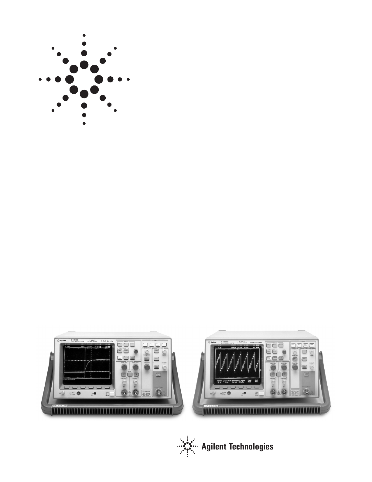
Agilent 54610B, 54615B and
54616B 500 MHz Oscilloscopes
Product Overview
The 54610B, 54615B and 54616B
oscilloscopes continue in the
tradition of Agilent Technologies’
popular 54600 series of digitizing
scopes by delivering the comfortable
feel of an analog oscilloscope with the
power of a digital architecture. In
addition, these oscilloscopes offer an
incredibly high level of digitizing
performance to give you confidence
in your critical measurements at a
fraction of the price that you
might expect.
The Feel of Analog
When you’re troubleshooting, you
want to stay focused on two things:
your circuit and the scope’s display.
You don’t want to waste time
pressing buttons or waiting for the
scope to update. That’s why the
straightforward front panel and
real-time display make analog scopes
such vital pieces of equipment for
troubleshooting.
You’ll feel right at home with these
three digitizing oscilloscopes because
they preserve the easy usability of
analog. Front-panel controls look
and function like the controls on your
old analog scope. You don’t have to
change the way you work, which
means you won’t lose time getting
used to a new style of test equipment.
In addition to front-panel controls,
display quality is also a critical factor
in selecting an oscilloscope. The multiprocessor architecture used in these
scopes has been designed for incredibly fast display updates, producing
the interactive display responsiveness
you require. When you make front
panel setup changes, or if your input
signal changes dynamically, you see
the results instantly.
Another important aspect of analog
oscilloscopes is variable display
intensity as a function of waveform
dynamics. Agilent’s proprietary display system emulates this characteristic. Slowly changing portions of
waveforms appear brighter on the
display, while rapidly changing portions appear dimmer. No other digital scopes produce waveforms that
provide this much visual information
or look this similar to analog.
• 500 MHz bandwidth
• 20 MSa/s, 1 GSa/s and 2 GSa/s
sample rates
• 1 ns peak detect (54615B/16B
only)
• Analog feel and digital power for
precise, accurate troubleshooting
The high speed answer for low-speed budgets!
• The industry’s lowest-cost 500 MHz
digital scope. (54610B)
• Single-shot bandwidths as high as
500 MHZ and sample rates up to 2 GSa/s
• 1 ns peak detect at all sweep speeds.
(54615B/16B)
Page 2

2
The Power of Digital
The power of digital opens up entirely new possibilities, such as pretriggering. Pretriggering lets you look
back in time to see what was going on
before the trigger event occurred.
This can be valuable for example, in
finding the cause of a system crash.
Precise, dependable results are yet
another benefit of the digital architecture. With the timebase ranging
from 5 s/div all the way down to 1
ns/div, you’ll get more insight into
waveform details. Plus, a horizontal
accuracy delivers more dependable
results allowing you to measure critical timing specs more accurately than
is possible with analog scopes.
Why put up with faint traces or flickering displays? These digital displays
are bright and stable, so there’s no
squinting, no need for a viewing
hood, no more headaches. You’ll see
what you need to see, across a wide
range of sweep speeds and input frequencies.
The power of the digital architecture
also allows many automated features
not possible in the analog domain.
These productivity enhancing features
help you get your job done easier and
faster:
• Autoscale frees you from manually
rescaling the scope every time you.
move the probe from test point
to test point. Simply press the
Autoscale key, and the scope will
automatically set voltage, time,
and trigger parameters for you.
• With Autostore, the waveform
displays at full brightness while
all previously-acquired waveforms
remain on the scope’s screen at
half brightness. This allows you to
see a history of waveform activity
while simultaneously viewing the
current waveform. This is a great
tool for analyzing worst-case jitter
and noise, or for permanently
capturing infrequent waveform
anomalies.
• Automatic measurements of voltage, frequency, and time, plus
user-defined cursor measurements
make waveform characterization
fast and easy.
• Save and recall traces and setups
for quick and easy testing and
waveform comparisons.
• With one of the optional modules,
a hardcopy of the screen is as easy
as connecting a printer and pressing the PRINT key.
• All setups and measurements can
be remotely controlled for test
automation and analysis using one
of the optional GPIB or RS-232/
parallel modules.
• Even when operating at slow
sweep speeds, the 54615B and
54616B’s 1 ns peak detect mode
will ensure capture of fast transient events that you might otherwise miss.
Measurement Confidence
The analog-like feel and automated
digital features will surely make the
art of troubleshooting fast and easy.
But do these scopes have the level of
performance to confidently capture
your high-speed single-shot and
repetitive signals? No other
oscilloscope, analog or digital, has
the combined level of performance of
the Agilent 54610B, 54615B and
54616B at this price. With these
scopes, you can have confidence in
your measurements. You won’t have
to worry about possibly missing
high-speed information, such as
narrow glitches.
Even though the 54610B is the least
expensive 500 MHz oscilloscope on
the market, it has analog performance that is similar to higher cost
oscilloscope. The 54610B is ideal for
production line test applications.
The 54615B and 54616B combine
500 MHz bandwidth, 1 GSa/s and
2 GSa/s sampling, and 1 ns digital
peak detect on both channels simul-
taneously to ensure high-fidelity
capture of single-shot or repetitive
waveforms. In fact, when using the
scopes’ 1 ns digital peak detect, they
effectively maintain a 1 GSa/s sample
rate on all timebase ranges. You now
have the ability to always capture
glitches as narrow as 1 ns regardless
of the scopes’ sweep rate.
Because of finite amounts of highspeed acquisition memory, digitizing
scopes ordinarily reduce real time
sampling rates in order to capture
longer spans of time on the slower
sweep ranges. When this happens,
waveform anamolies such as narrow
glitches can be missed if they occur
between the actual samples. This is a
common worry and concern among
many digitizing scope users. The
54615B samples and stores all information at a maximum rate of 1 GSa/s
on all sweep speeds faster than 1
microsecond per division. The
54616B can sample at 2 GSa/s at
all sweep speeds faster than
500 nanoseconds per division. On
the slower sweep speeds, these
scopes do indeed, reduce realtime
sample rate, thereby increasing the
uncertainty of capturing narrow
events. However, by engaging the
1 ns peak detect mode, the 54615B
and 54616B effectively maintain a
1 GSa/s sample rate even on the
slowest sweep speeds. This means
that single-shot, 1 ns events won’t be
missed, even when set up to view
extremely slow waveform activity.
Optional Enhancement Modules
Adding enhanced capabilities to your
Agilent 54615B and 54616B scope is
now as easy as snapping on a module.
It’s easy to add direct hard copy, PC
connectivity, remote control, and
advanced measurement capabilities,
such as Fast Fourier Transform (FFT)
and waveform template testing.
You’ll solve problems and boost
productivity in ways that just aren’t
possible with ordinary scopes.
Page 3
3
Agilent 54600-Series Scope Modules
54650A GPIB Interface
Module
54652B RS-232/Parallel
Interface Module
54657A Measurement/
Storage Module
with GPIB Interface
54659B Measurement/
Storage Module
with RS-232 and
Parallel Interfaces
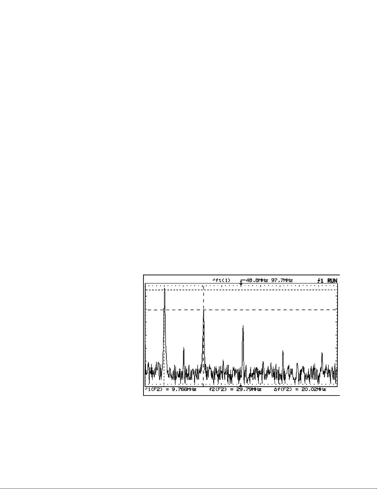
The 54657A and 54659B Measurement/Storage modules allow you to
add flexible, high-performance tools
such as FFT to view signals in the frequency domain. Having both time
and frequency perspectives gives you
an entirely new level of power for
locating and understanding circuit
failures. Common problems such as
harmonic distortion, which is difficult or impossible to see in the time
domain, become much easier to see
when you use the FFT to look at the
frequency domain.
This module also adds time-domain
features that make catching intermittent failures easy. Unattended signal
monitoring and failure detection features allow you to simply set up the
scope and walk away. It will monitor
the signal by comparison to a waveform mask template. When the failure mode appears, the scope will capture the signal and follow your
instructions for time stamping, printing, or storing the signal for later
analysis. The measurement/storage
module provides other features to
make your work easier, including
measurements of channel-to-channel
delay and phase, user-definable voltage levels for timing measurements,
and extended math functions and
cursor readout.
PC Connectivity Made Easy
Receive Agilent IntuiLink
software FREE with the purchase of
any module. Use it to retrieve
waveform images, waveform data,
and automatic measurements into
Microsoft Excel and Word with no
programming. Or, for customers
already using the BenchLink Scope,
use the optional, standalone application to transfer screen images or data
from the 54610B, 54615B or 54616B
oscilloscopes to the PC. From there,
the Windows Clipboard makes it a
snap to create polished reports by
moving scope results into your
Windows applications. And for
archiving, just store the images on
disk in either PCX or TIF formats,
with time and date stamps, too.
IntuiLink for the 54600-series scope
lets you transfer the waveform data
(stored as time/ voltage pairs) for
analysis in your favorite analysis/statistical package. You can also use
scope waveforms as input for
arbitrary waveform generation
by teaming up the Agilent 33120A
Arbitrary Waveform Generator
and the Agilent IntuiLink software
for Arb .
Enhanced TV/Video Trigger for
Precision Video Measurements
With the addition of Option 005, your
54610B, 54615B or 54616B
oscilloscope has the ability to trigger
and perform highly detailed
measurements on the video
components of your system. You
will gain the following features:
• IRE Graticule
• Video Autoscale: Scales the
display to the IRE graticule
• Cursor readout in IRE units
• NTSC, PAL, PAL-M, SECAM,
and generic video formats
• Triggering on any specified line
of video
• Trigger modes of:
Selected line number
All lines
Field 1
Field 2
All Fields
• Full bandwidth vertical output
• TV trigger output
FFT measurement with the 54657A or 54659B Measurement Storage module
Page 4

4
Vertical System
Channels 2
Bandwidth (-3dB)
[1]
dc to 500 MHz
AC Coupled
[1]
10 Hz to 500 MHz
Max sample rate: 54610B 20 MS/s
54615B 1 GS/s
54616B 2 GS/s
Sensitivity 2mV/div to 5 V/div
Accuracy
[2]
±2%
Vernier Accuracy
[2]
±2%
Rise Time 700 ps (calculated)
Coupling dc, ac, and ground
Input R 1 MΩ or 50 Ω
Input C ~ 9 pF
Bandwidth Limit approximately 30 MHz
Inversion CH 1 and CH 2
CMRR
≥
20 dB at 50 MHz
Dynamic Range ± 12 div from center
screen
Maximum Input 250 V (dc + peak ac) for
5 Vms in 50 Ω mode
50 Ω Protection Protects 50 Ω load from
excessive voltage
Probe Sense Automatic readout of 1X,
10X, 20X, and 100X probes
Voltage Measurement Accuracy
Single Cursor
[3]
Vertical Accuracy ± 1.2%
of full scale ± 0.5% of
position value
Dual Cursor
[3]
Vertical Accuracy ± 0.4%
of full scale
Math Functions CH1 + or - CH2
Horizontal System
Main and Delayed
Main Sweep Range 5 s/div to 1 ns/div
Delayed Sweep Range Up to 200X main sweep,
as fast as 1 ns/div
Accuracy 54610B ± 0.01%
54615B/16B ±0.005%
Resolution 54610B 25 ps
54615B/16B 20 ps
Delay Jitter 54610B 10 ppm
54615B/16B ≤ 1 ppm
Pretrigger Delay (negative time)
54610B ≥ 10 divison
54615B The greater of 30 µs or
60 div, not to exceed 100s
54616B The greater of 15 µs or
60 div, not to exceed 100s
Posttrigger Delay The greater of 10 ms
(Trigger to start
20,000 div, not to exceed
of sweep) 100 s
Time Skew Adjustable over a range of
± 25 ns to remove effects
of cabling and probe
delays
Roll Mode
At sweep speeds of 200
ms/div
or slower, waveform data moves across
the display from right to
left with no dead time.
Display can be free
running (non triggered)
or triggered to stop on
a trigger event.
Time Measurement Accuracy
Cursor accuracy ± 0.005% of reading.
∆t & 1/∆t ± 0.2% of full scale,
± 100 ps
Trigger System
Internal Triggering
Sensitivity (Ch 1 and 2)
dc to 100 MHz: 0.5 div or 5 mV
100 MHz to
500 MHz: 1 div or 10 mV
Coupling ac, dc, HF reject, LF reject,
and noise reject (LF & HF
reject -3dB at approx.
50 kHz)
Modes Auto, Autolevel, Normal,
Single, & TV
External Triggering
Range ± 2V
Sensitivity
dc to 100 MHz: < 75mV
100 MHz to
500 MHz: < 150mV
Coupling dc, ac
Input R&C 1 MΩ, ~12 pF or 50 Ω
selectable
Maximum Input 250 V (dc + peak ac) or
5 Vrms in 50 Ω mode
50 Ω Protection Protects 50 Ω load from
excessive voltage
Probe Sense Automatic readout of 1X,
10X, 20X, and 100X probes
TV Triggering TV line and field. 0.5 div of
composite sync for stable
display (Ch 1 and Ch 2)
Line Counting Delay time calibrated in
NTSC and PAL line numbers
All Field Trigger Oscilloscope triggers on
the vertical sync pulse in
both fields, allowing use
with noninterlaced video
Holdoff Adjustable from 300 ns to
approximately 13 ns
X-Y Operation
Bandwidth X and Y same as vertical
system
Phase Difference ± 3° at 100 kHz (54610B)
± 3° at 10 MHz
(54615B/16B)
Display System
Display 7-in raster CRT
Resolution 255 vertical by 500 hori-
zontal points
Controls Front-panel intensity
control
Graticule 8x10 grid or frame
Autostore Saves previous sweeps in
half bright display and the
most recent sweep in full
bright
Acquisition System
Max Sample Rate 20 MSa/s (54610B)
(single shot) 1 GSa/s (54615B)
2 GSa/s (54616B)
Resolution 8 bits
Simultaneous
Channels 2
Record Length ≤ 4,000 (54610B)
≤ 5,000 (54615B/16B)
Usable Single-Shot 2 MHz (54610B)
Bandwidth 250 MHz (54615B)
500 MHz (54616B)
Peak Detect 50 ns glitch capture
(54610B)
1 ns glitch capture
(54615B/16B)
Average Number of averages
selectable at 8, 64, 256
Advanced Functions
Automatic
Measurements are contin-
Measurements
uously updated
Voltage V
avg
, V
rms
, V
p-p
, V
top
,
V
base
, V
min
, and V
max
Time Frequency, Period,
+Width,
-Width, Duty Cycle, Rise
Time, and Fall Time
Cursors Manually or automatically
placed
Setup Functions
Autoscale Sets the vertical and hori-
zontal deflection and the
trigger level. Requires a
signal with > 0.5% duty
cycle, > 49 Hz frequency,
and > 20 mV
p-p
Trace Memory Two volatile pixel memo-
ries
[1] Upper bandwidth reduced 2 MHz per degree Celsius
above 35°C.
[2] Temperature ± 10°C from calibration.
[3] Magnification is used below 7 mV/div range. Below
7 mV/div dull scale is defined as 56 mV full scale.
Agilent 54610B, 54615B and 54616B Performance Specifications and Characteristics
Page 5

5
General
Power Line Requirements
Line Voltage Range 100 Vac to 240 Vac
Line Voltage Selection Automatic
Line Frequency 45 Hz to 440 Hz
Max Power 220 VA (54610B)
Consumption
300 VA (54615B/16B)
Environmental Characteristics
The instruction meets
the requirements to
MIL-T-28800E for Type III,
Class 3, Style D equipment
as described below.
Ambient Temperature
Operation -10°C to +55°C
Nonoperation -51°C to +71°C
Humidity
[1]
Operating 95% RH at 40°C for 24 Hrs
Nonoperating 90% RH at 65°C for 24 Hrs
Altitude
Operating to 4,500 m (15,000 ft.)
Nonoperating to 15,000 m (50,000 ft.)
EMI (commercial) CISPR11 Group 1 Class A
EMI (MIL-T-28800E) EMI meets the require-
ments in accordance with
MIL-T-28800E (prior to
Interim Amendment 1)
and MIL-STD 461C as
described below.
CE01 Part 2 narrow band
requirements up to 15 kHz
CE03 Part 2
CS01 Part 2
CS02 Part 2 limited to 100 MHz
CS06 Part 5 limited to 400 V
RE01 Part 5 measured at 6 inch-
es, exceptioned from
19 kHz to 50 kHz.
RE02 Part 2 (limited to 1 GHz)
full limits of Class A1c and
A1f, with Option 002
installed. Without Option
002 installed 10 dB relax-
ation, 14 kHz to 100 kHz.
RS03 Part 2, limited to 1V/meter
from 14 kHz to 1 GHz.
Slight trace susceptibility
from 450 MHz to 600 MHz
and at 950 MHz.
Vibration
Operating 15 minutes along each of
the 3 major axes; 0.025
inch p-p displacement, 10
Hz to 55 Hz in one minute
cycles. Held for 10 minutes at 55 Hz (4 g at 55Hz).
Nonoperating Survival random vibration,
5 Hz to 500 Hz at 2.41 g
rms
Shock Operating: 30 g, 1/2 sine,
11 ms duration, 3 shocks
per axis along major axis,
total of 18 shocks.
Size (excluding handle)
Height 172 mm (6.8 in)
Width 322 mm (12.7 in)
Depth 317 mm (12.5 in)
Weight 6.6 kg (145 lbs)
Safety CSA Certification, IEC -----
1010
Warranty 3 years (additional 2 years
with option W50)
54650A GPIB Interface Module
Provides full remote control and hard copy to
GPIB printers and plotters. Programming is in
accordance with IEEE 488.2. With the addition of
this module, the scope’s two pixel memories
become nonvolatile. An operating and programming manual and a programming examples disk
are supplied.
Specifications The interface capabilities
of the 54600-series oscilloscope with this module
installed are as defined by
IEEE 488.1 as SH1, AH1,
T5, L4, SR1, RL1, PP1,
DC1, DT1, CO, and E2
Printer/Plotter All HP GPIB printers and
Supported HP-GL compatible plot-
ters.
54652B RS-232/Parallel Interface Module
Provides full remote control via RS-232 and printing via parallel in one module. The RS-232 can
also be configured for printing when not being
used for remote control.
Specifications
Connector Type 9 pin (M) DTE port, works
RS-232 with 34398A RS-232 cable
Protocols Xon/Xoff, hardware
Databits 8
Parity None
Baud Rates 1200, 2400, 9600, or 19200
Printer/Plotter All HP RS-232 printers and
HP-GL compatible plotters
Connector Type 25 pin (F) connector,
works with C2950A parallel printer cable
Supported Printers All HP parallel printers and
Epson FX-80 or HP PCL
compatible printers.
54657A and 54659B Measurement/
Storage Modules
With the addition of these modules, the 54600series oscilloscope will provide all of the following
features.
19 Automatic Measurements consisting of:
Voltage V
amp
, V
avg
, V
rms
, V
p-p
,
V
pre
, V
ovr
, V
top
, V
base
,
V
min
, and V
max
Time Delay, Duty Cycle,
Frequency, Period, Phase
Angle, Rise Time, Fall
time, + Width, and - Width
Thresholds User selectable among
10%-90%, 20%-80%, or
absolute voltage levels.
Cursor Readout Voltage or percentage;
Modes Time or phase angle
Waveform Math Functions
Function 1 Addition, subtraction, and
multiplication
Function 2 Differentiation, integra-
tion, and FFT
FFT
Windows Exponential, flat top,
Hanning and rectangular
Samples 1024 points
Trace Memory Up to 100 nonvolatile
memories
Memories 1–3 High-speed storage with-
out compression
Memories 4–100 Storage with compres-
sion. Storage time is
approximately 7 seconds.
Number of traces that can
be stored is a function of
complexity, with the minimum being 4 highly complex traces and the maximum being 96.
Memory Labeling An on-screen text editor is
provided for creating
labels up to 20 characters.
Each label contains the
date and time it was
saved.
Real Time Clock 24-hour format with bat-
tery backup. Can be set
from front panel.
Unattended Waveform Monitoring
Testing Method Comparison to waveform
mask
Number of Masks 2
Page 6

6
Mask Generation Automask, controlled
from the front panel, gen-
erates a mask from a dis-
played waveform with
selectable tolerance.
Mask editor function
allows pixel-by-pixel edit-
ing and line drawing.
Smoothing function per-
forms a running average
of 3 pixels.
Test Region Pixel-by-pixel selectable
Fail Region Inside: signal fails if it
falls inside the region
bounded by the mask
template
Outside: signal fails if it
falls outside the region
bounded by the mask
Action on Failure Save failed trace to mem-
ory with date and time of
the failure
Print failed trace with
date and time of the fail-
ure
Count the failure and
maintain pass/fail statis-
tics while continuing the
test
Hard Copy and Programmability Interface
54657A: GPIB
54659B: RS-232 and
Parallel
Opt. 005 Enhanced TV/Video Triggering
Video Autoscale Scales the display to the
NTSC IRE Graticules
Video Formats NTSC, PAL, PAL-M,
SECAM, and Generic
Trigger Modes Line (number) of Field 1,
2, or alternate fields
All Lines
Field 1 (defined as that
field with 3 lines of verti-
cal sync starting at line 4)
is actually color field 1
or 3
Field 2 (defined as that
field with 3 lines of verti-
cal sync starting at the
midpoint of line 3) is actu-
ally color field 2 or 4
All Fields
Trigger Sources Video trigger from either
CH1 or CH2
Trigger Sensitivity Video trigger requires
>0.5 divisions of composite sync
Vertical Out Rear panel BNC (f)
Source impedance: 50 Ω
Signal source selected by
internal trigger source
Amplitude: Approx. 90
mVp-p into 50 Ω for a full
scale display
TV Trigger Out Rear-panel BNC (f)
Amplitude: TTL
Delay from input:
Approximately 40 ns
IntuiLink Software Operating Characteristics
Agilent IntuiLink Software for the
54600-series scopes
PC Connectivity Made Easy
Receive IntuiLink software for the 54600 FREE
with the purchase of any module listed above.
Use it to retrieve waveform images, waveform
data—even automatic measurements—directly
into Microsoft Excel and Word without programming. Additionally, an ActiveX control simplifies
programming in Visual Basic, VBA, Visual C++,
Agilent VEE, and National Instruments LabVIEW.
For more comprehensive information on
IntuiLink, please see the IntuiLink datasheet
with Agilent publication number 5980-3115EUS
or visit the URL:
www.agilent.com/find/intuilink
34810B BenchLink Scope
Standalone Option
Screen Image Capture
Oscilloscope screen images (pixel-based representation of scope screen) can be shown on a
computer’s display and copied to the Clipboard
or saved in PCX or TIF formats. Time and date of
capture, as well as the scope used, can be saved
as part of the image.
Waveform Data Capture
Waveform data (arranged in time-voltage pairs)
can be shown on a computer’s display. Data can
be copied to the Clipboard or saved in commaseparated (*.csv) or tab-separated (.prn) ASCII
format. Paste from the Clipboard using timevoltage data. You can define number of points
transferred per waveform, as well as the color of
the waveform on the computer screen.
Instrument Setup
Instrument front-panel setups can be saved to a
file for later recall.
s
Agilent 54610B, 54615B and 54616B Performance Specifications and Characteristics (continued)
IntuiLink screenshot for 54600.xls
A
Time (Sec
1
-0.00249 2.3125 10010000
2
-0.00247 2.1875 10010000
3
4
-0.00245 2.1875 10010000
5
-0.00243 2.25 10010000
-0.00241 2.1875 00010000
6
7
-0.00239 2.1875 00010000
8
-0.00237 200010000
9
-0.00235 2.0625 00010000
10
-0.00233 1.875 00010000
11
-0.00231 1.875 00010000
-0.00229 1.875 11110000
12
-0.00227 1.75 11100000
13
-0.00225 1.875 11100000
14
15
-0.00223 1.6875 11100000
16
-0.00221 1.6875 11100000
17
-0.00219 1.6875 01100000
18
-0.00217 1.5625 01100000
-0.00215 1.5625 01100000
19
-0.00213 1.5 01100000
20
21
-0.00211 1.5 01100000
22
-0.00209 1.4375 10100000
23
-0.00207 1.375 10100000
-0.00205 1.25 10100000
24
25
-0.00203 1.25 10100000
26
-0.00201 1.1875 10100000
27
-0.00199 1.1875 00100000
28
-0.00197 1.125 00100000
29
-0.00195 1.0625 00100000
BCDEFGHI J
CHAN1 Dig0 Dig1 Dig2 Dig3 Dig4 Dig5 Dig6 Dig7-15
Page 7

7
Ordering Information
54610B Two-channel,
500 MHz, 20 MSa/s oscilloscope
(includes two 10073B 10:1 passive
probes and user’s guides)
54615B Two-channel, 500 MHz, 1
GSa/s Oscilloscope
(Includes two 10073B 10:1
passive probes and user’s guides)
54616B Two-channel, 500 MHz, 2
GSa/s Oscilloscope
(Includes two 10073B 10:1
passive probes and user’s guides)
Options
Opt. 001 RS-03 Magnetic interface
shielding added to CRT
Opt. 002 RE-02 Display Shield added
to CRT (to reduce radiated interface)
Opt. 0B0 Delete Manual
Opt. W50 Additional 2-year warranty
starting at
Opt. 1BP Mil Std 45662A cal with test data
Opt. 005 Enhanced TV/Video
measurements and triggering
Opt. 090 Delete probes
Opt. 101 10098A Accessory pouch
& front panel cover
Opt. 103 54654A Operator’s training kit
Opt. 104 1185A Carrying case
Opt. 1CM 5062-7345 Rack mount kit
Opt. 106 34810B BenchLink
scope (v1.4 or greater) for Windows
Interface, Measurement and Storage Modules
(all modules ship with free IntuiLink
scope software for easy transfer of images
and data to Microsoft Excel and Word)
54650A GPIB Interface module
54652B RS-232/Parallel interface
module
54657A GPIB Measurement/
storage module
54659B RS-232/Parallel measurement/
storage module
E2657A Measurement connectivity
kit for GPIB, Includes
54657A GPIB measurement/storage module,
34810B BenchLink Scope software and
10833A GPIB cable.
E2659A Measurement connectivity
kit for RS-232, Includes
54659A RS-232/parallel measurement/
storage module, 34810B BenchLink Scope
software and 34398A RS-232 cable kit.
Accessories
1183A Testmobile
10098A Front panel cover and pouch
(also orderable as Option 101)
10072A SMT probe tips for 1007X
probes (supplied with 8 grabbers)
10070C 1:1 Passive probe
10073C 10:1 500 MHz passive probe
10076A 4 kV 250 MHz high voltage
probe
10077A Accessory kit for 10076A
high voltage probe
1144A 800MHz Active probe
1141A 200MHz Differential probe
1142A Probe control and
power module for 1141A
N2774A 50 MHz current probe
N2775A power supply for N2774A
Page 8

Agilent Technologies’ Test and Measurement
Support,
Services, and Assistance
Agilent Technologies aims to maximize the value
you receive, while minimizing your risk and problems. We strive to ensure that you get the test
and measurement capabilities you paid for and
obtain the support you need. Our extensive support resources and services can help you choose
the right Agilent products for your applications
and apply them successfully. Every instrument
and system we sell has a global warranty.
Support is available for at least five years beyond
the production life of the product. Two concepts
underlie Agilent's overall support policy: "Our
Promise" and "Your Advantage."
Our Promise
Our Promise means your Agilent test and measurement equipment will meet its advertised performance and functionality. When you are choosing new equipment, we will help you with product information, including realistic performance
specifications and practical recommendations
from experienced test engineers. When you use
Agilent equipment, we can verify that it works
properly, help with product operation, and provide basic measurement assistance for the use of
specified capabilities, at no extra cost upon
request. Many self-help tools are available.
Your Advantage
Your Advantage means that Agilent offers a wide
range of additional expert test and measurement
services, which you can purchase according to
your unique technical and business needs. Solve
problems efficiently and gain a competitive edge
by contracting with us for calibration, extra-cost
upgrades, out-of-warranty repairs, and on-site
education and training, as well as design, system
integration, project management, and other professional engineering services. Experienced
Agilent engineers and technicians worldwide can
help you maximize your productivity, optimize the
return on investment of your Agilent instruments
and systems, and obtain dependable measurement accuracy for the life of those products.
By internet, phone, or fax, get assistance with all
your test & measurement needs
Online assistance:
www.agilent.com/find/assist
Phone or Fax
United States:
(tel) 1 800 452 4844
Canada:
(tel) 1 877 894 4414
(fax) (905) 282-6495
Europe:
(tel) (31 20) 547 2323
(fax) (31 20) 547 2390
Japan:
(tel) (81) 426 56 7832
(fax) (81) 426 56 7840
Latin America:
(tel) (305) 269 7500
(fax) (305) 269 7599
Australia:
(tel) 1 800 629 485
(fax) (61 3) 9210 5947
New Zealand:
(tel) 0 800 738 378
(fax) 64 4 495 8950
Asia Pacific:
(tel) (852) 3197 7777
(fax) (852) 2506 9284
Product specifications and descriptions in this
document subject to change without notice.
Copyright
©
2001 Agilent Technologies
Printed in USA May 15, 2001
5968-7292EN
Agilent Technologies Warranty and Related Literature
Agilent hardware products are warranted against
defects in materials and workmanship for a period of one year from date of shipment. Some
newly manufactured Agilent products may contain remanufactured parts, which are equivalent
to new in performance. If you send us a notice of
such defects during the warranty period, we will
either repair or replace hardware products that
prove to be defective.
Agilent software and firmware products that are
designated by Agilent for use with a hardware
product are warranted for a period of one year
from date of shipment to execute their programming instructions when properly installed. If you
send us notice of defects in materials or workmanship during the warranty period, we will
repair or replace these products, so long as the
defect does not result from buyer supplied hardware or interfacing. The warranty period is controlled by the warranty statement included with
the product and begins on the date of shipment.
 Loading...