

Page 1
• 225 MHz bandwidth
(optional 1.5, 3, 5,
or 12.4 GHz)
• 10- or 12-digit resolution
with 1 s gate time
• GPIB interface and
IntuiLink connectivity
software standard
• Data transfer rate of up
to 200 fully formatted
measurements/second
A family of universal and
RF counters to meet your needs
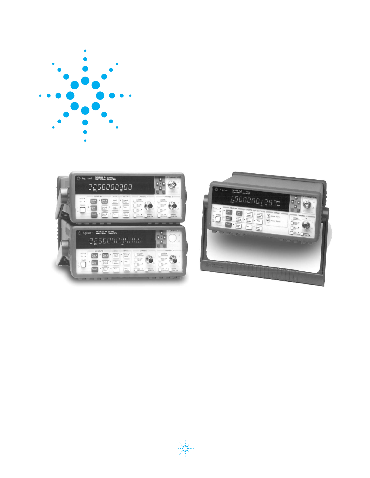
Agilent Technologies 53131A/
132A/181A high-performance
counters give you fast, precise
frequency measurements at
an affordable price. These
counters feature an intuitive
user interface
and one-button
access to frequently
used functions so you can make accurate
measurements quickly and easily.
Agilent 53131A/132A/181A Counters
High-performance, low-cost counters simplify and
speed systems and bench frequency measurements
Data Sheet
Agilent Technologies
Page 2

2
Real-time digital signal processing
technology is used to analyze data
while simultaneously taking new
readings, speeding measurement
throughput. The technology,
developed for Agilent’s high-end
line of modulation domain
analyzers, allows the counters
to gather more data for each
measurement, so you get higherresolution measurements in
a fraction of the time it takes
other counters.
The 53131A/132A/181A counters
offer built-in statistics and math
functions so you can scale measurements and simultaneously
measure and track average,
min/max and standard deviation.
Automated limit testing lets you
set upper and lower limits for
any measurement. An analog
display mode lets you see at a
glance whether a measurement
is within pass/fail limits. The
counters flag out-of-limit conditions and can generate an output
signal to trigger external devices
when a limit is exceeded. For
quick access to frequently used
tests, a single keystroke recalls
up to 20 different stored frontpanel set-ups.
For computer-controlled systems
applications, each counter includes
a standard GPIB interface with
full SCPI-compatible programmability and a data transfer rate
of up to 200 fully formatted
measurements per second. The
standard RS-232 talk-only interface provides printer support
or data transfer to a computer
through a terminal-emulation
program.
Agilent 53131A Universal Counter
The two-channel 53131A counter
offers 10 digits per second of
frequency/period resolution and
a bandwidth of 225 MHz. Time
interval resolution is specified
at 500 ps. An optional third
channel provides frequency
measurements up to 3 GHz, 5 GHz,
or 12.4 GHz. Standard measurements include frequency, period,
ratio, time interval, pulse width,
rise/fall time, phase angle, duty
cycle, totalize, and peak voltage.
Agilent 53132A Universal Counter
For applications requiring higher
resolution, the 53132A offers the
same features and functions as
the 53131A, with up to 12 digits/
sec frequency/period resolution
and 150 ps time interval resolution. In addition, the 53132A
offers advanced arming modes
for time interval measurements.
Agilent 53181A RF Counter
Optimized for RF applications,
the single-channel 10 digit/s
53181A measures frequency,
period and peak voltage. A digitblanking function lets you easily
eliminate unnecessary digits when
you want to read measurements
quickly. For higher-frequency
measurements, choose an optional
second channel that provides
measurements up to 1.5 GHz,
3 GHz, 5 GHz, or 12.4 GHz. A
self-guided shallow menu makes
this counter exceptionally
easy to use.
Page 3

3
Agilent IntuiLink provides easy access
to the counter’s data from your PC
The Agilent 53131A/132A/181A
counters, capture precise frequency
and time measurements.
IntuiLink software allows that
data to be put to work easily. You
work in a familiar environment
at all times, using PC applications
such as Microsoft Excel® or Word®
to analyze, interpret, display,
print, and document the data
you get from the counter.
It gives you the flexibility to
configure and run tests from
your PC making data gathering
more convenient.
Agilent IntuiLink lets you:
• configure tests, including
measurement type, number
of readings, measurement
speed, and more.
• choose display modes
from real-time strip chart,
histogram, readout, and
table mode.
• scale measurements data.
• copy captured data to
other programs.
Optional timebases offer
increased stability
Optional timebases are available
for 53131A/132A/181A counters
to increase measurement accuracy.
Option 010 provides a high stability oven timebase with aging
of less than 5 x 10
-10
per day.
1-year warranty
Each counter comes with operating, programming and service
manuals, IntuiLink software,
a power cord and a full 1-year
warranty.
Time Base
Internal Time Base Stability (see graph 3 for timebase contribution of measurement error)
Standard Medium Oven High Oven Ultra High Oven
(0° to 50°C) (Option 001) (Option 010) (Option 012 for 53132A only)
Temperature Stability (referenced to 25°C) < 5 x 10
-6
< 2 x 10
-7
< 2.5 x 10
-9
< 2.5 x 10
-9
Aging Rate Per Day: < 4 x 10
-8
< 5 x 10
-10
< 1 x 10
-10
(after 30 days) Per Month: < 3 x 10
-7
< 2 x 10
-7
< 1.5 x 10
-8
< 3 x 10
-9
Per Year: < 2 x 10
-8
Turn-on stability vs. time
(in 30 minutes) < 2 x 10
-7
< 5 x 10
-9
< 5 x 10
-9
referenced to 2 h referenced to 24 h referenced to 24 h
Calibration Manual Adjust Electronic Electronic Electronic
Note that power to the time base is maintained when the counter is placed in standby via the front panel switch. The internal fan will continue to operate
when in standby to maintain long-term measurement reliability.
Page 4

Input Specifications
Channel 1 & 2 (53131A, 53132A)
1
Channel 1 (53181A)
Frequency Range
dc Coupled dc to 225 MHz
ac Coupled 1 MHz to 225 MHz (50 Ω)
30 Hz to 225 MHz (1 MΩ)
FM Tolerance 25%
Voltage Range and Sensitivity (Sinusoid)
2
dc to 100 MHz 20 mVrms to ±5 V ac + dc
100 MHz 30 mVrms to ±5 V ac + dc
to 200 MHz
200 MHz 40 mVrms to ±5 V ac + dc
to 225 MHz (all specified at 75 mVrms
with opt. rear connectors)
3
Voltage Range and Sensitivity
(Single-Shot Pulse)
2
4.5 ns to 10 ns 100 mVpp to 10 Vpp
Pulse Width (150 mVpp with optional
rear connectors)
3
>10 ns 50 mVpp to 10 Vpp
Pulse Width (100 mVpp with optional
rear connectors)
3
Trigger Level
2
Range ± 5.125 V
Accuracy ± (15 mV + 1% of trigger level)
Resolution 5 mV
Damage Level
50 Ω 5 Vrms
0 to 3.5 kHz, 350 Vdc + ac pk
1 MΩ
3.5 kHz to 350 Vdc + ac pk linearly
100 kHz, 1 MΩ
derated to 5 Vrms
>100 kHz, 5 Vrms
1 MΩ
Input Characteristics
Channel 1 & 2 (53131A, 53132A)
1
Channel 1 (53181A)
Impedance 1 MΩ or 50 Ω
1 MΩ 30 pF
Capacitance
Coupling ac or dc
Low-Pass Filter
100 kHz, switchable
-20 dB at > 1 MHz
Input Selectable between Low,
Sensitivity Medium, or High (default).
Low is approximately 2x
High Sensitivity.
Trigger Slope Positive or Negative
Auto Trigger Level
Range 0 to 100% in 10% steps
Frequency > 100 Hz
Input Amplitude
> 100 mVpp
(No amplitude modulation)
Attenuator
Voltage Range x10
Trigger Range x10
Input Specifications
4
Channel 3 (53131A, 53132A)
Channel 2 (53181A)
Frequency Range
Option 015 100 MHz to 1.5 GHz
(for 53181A (see Opt. 030 for
only) additional specs)
Option 030 100 MHz to 3 GHz
Option 050 200 MHz to 5 GHz
Option 124 200 MHz to 12.4 GHz
Power Range and Sensitivity (Sinusoid)
Option 030 100 MHz to 2.7 GHz:
-27 dBm to +19 dBm
2.7 GHz to 3 GHz:
-21 dBm to +13 dBm
Option 050 200 MHz to 5 GHz:
-23 dBm to +13 dBm
Option 124 200 MHz to 12.4 GHz
-23 dBm to +13 dBm
Damage Level
Option 030 5 Vrms
Option 050 +25 dBm
Option 124 +25 dBm
Characteristics
Impedance 50 Ω
Coupling AC
VSWR <2.5:1
External Arm Input Specifications
5
Signal Input Range
TTL Compatible
Timing Restrictions
Pulse Width > 50 ns
Transition Time < 250 ns
Start-to-Stop Time
> 50 ns
Damage Level 10 Vrms
External Arm Input Characteristics
5
Impedance 1 kΩ
Input Capacitance
17 pF
Start/Stop Slope Positive or Negative
External Time Base Input Specifications
Voltage Range 200 mVrms to 10 Vrms
Damage Level 10 Vrms
Frequency 1 MHz, 5 MHz, and 10 MHz
(53132A 10 MHz only)
Time Base Output Specifications
Output Frequency
10 MHz
Voltage > 1 Vpp into 50 Ω
(centered around 0 V)
1. Specifications and Characteristics for Channels
1 and 2 are identical for both common and
separate configurations.
2. Values shown are for X1 attenuator setting.
Multiply all values by 10 (nominal) when using
the X10 attenuator setting.
3. When the 53131A or 53132A are ordered with
the optional rear terminals (Opt. 060), the channel
1 and 2 inputs are active on both front and rear
of the counter. When the 53181A is ordered with
the optional rear terminal, the channel 1 input is
active on both front and rear of the counter. For
this condition, specifications indicated for the rear
connections also apply to the front connections.
4. When optional additional channels are ordered
with Opt. 060, refer to configuration table for
Opt. 060 under ordering info on page 8. There is
no degradation in specifications for this input,
as applicable.
5. Available for all measurements except Peak Volts.
External Arm is referred to as External Gate for
some measurements.
4
Instrument Inputs
Page 5

5
For Time or Digits Arming:
For Automatic or External Arming:
(and signals < 100 Hz using Timed Arming)
LSD Displayed:
RMS Resolution:
typical
see graphs for worst case resolution performance
For Automatic Arming:
Systematic Uncertainty:
typical
worst case
Trigger: Default setting is Auto Trigger at 50%
LSD Displayed:
RMS Resolution
(see graph 2):
typical
see graphs for worst case resolution performance
Frequency
2 Trigger Error
Gate Time
53132A t
res
200 ps
Gate Time =
or
Period
Frequency
2
兲
53181A t
650 ps
N
53131A t
650 ps
t
res
Gate Time
2
t
res
res
where N = 1 for standard channel Frequency < 1 MHz
4 for standard channel Frequency > 1 MHz
128 for optional channel
±
Gate Time
53181A t
t
acc
350 ps
1.25 ns
53131A t
350 ps
1.25 ns
±
Time Base Error
53132A t
acc
100 ps
500 ps
2 2 t
acc
res
Gate Time Number of Samples
2
4 t
(2 Trigger Error2)
res
Gate Time Number of Samples
53131A/181A 53132A
t
res
500 ps
t
jitter
50 ps
t
res
225 ps
t
3 ps
Frequency
or
Period
res
acc
t
Gate Time
Gate Time
jitter
Frequency
jitter
t
jitter
or
Period
Frequency
or
Period
Frequency
Period
or
Number of Samples = Gate Time x Frequency (Frequency < 200 kHz)
Systematic Uncertainty:
typical
worst case
Gate Time x 200,000
± Time Base Error ±
53131A/181A
t
acc
100 ps
300 ps
(Frequency > 200 kHz)
t
acc
Gate Time
53132A
t
acc
10 ps
100 ps
Frequency
Period
Trigger: Default setting is Auto Trigger at 50%
or
Page 6

Frequency (53131A, 53132A, 53181A)
Channel 1 and 2 (53131A, 53132A)
Channel 1 (53181A)
Range 0.1 Hz to 225 MHz
Channel 3 (53131A, 53132A)
Channel 2 (53181A)
Option 015 100 MHz to 1.5 GHz
(53181A only)
Option 030 100 MHz to 3 GHz
Option 050 200 MHz to 5 GHz
Option 124 200 MHz to 12.4 GHz
(Period 2 or 3 selectable via GPIB only)
Period (53131A, 53132A, 53181A)
Channel 1 and 2 (53131A, 53132A)
Channel 1 (53181A)
Range 4.44 ns to 10 s
Channel 3 (53131A, 53132A)
Channel 2 (53181A)
Option 015 0.66 ns to 10 ns
(53181A only)
Option 030 0.33 ns to 10 ns
Option 050 0.2 ns to 5 ns
Option 124 80 ps to 5 ns
Frequency Ratio (53131A, 53132A, 53181A)
Measurement is specified over the full signal
range of each input.
Results Range 10
-10
to 10
11
“Auto” Gate Time
100 ms
Time Interval (53131A, 53132A)
Measurement is specified over the full signal
ranges6of Channels 1 and 2.
Results Range -1 ns to 105s
LSD 500 ps (53131A)/150 ps (53132A)
Phase (53131A, 53132A)
Measurement is specified over the
full signal range of Channels 1 and 2.
Results Range -180° to +360°
Duty Cycle (53131A, 53132A)
Measurement is specified over the full
signal range of Channel 1. However, both the
positive and negative pulse widths must be
greater than 4 ns.
Results Range 0 to 1 (e.g. 50% duty cycle
would be displayed as .5)
Rise/Fall Time (53131A, 53132A)
Measurement is specified over the full signal
ranges of Channel 1. The interval between the
end of one edge and start of a similar edge
must be greater than 4 ns.
Edge Selection Positive or Negative
Trigger Default setting is Auto Trigger
at 10% and 90%
Results Range 5 ns to 105s
LSD 500 ps (53131A)/150 ps (53132A)
Pulse Width (53131A, 53132A)
Measurement is specified over the full signal
range of Channel 1. The width of the opposing
pulse must be greater than 4 ns.
Pulse Selection
Positive or Negative
Trigger Default setting is Auto Trigger
at 50%
Results Range 5 ns to 105s
LSD 500 ps (53131A)/150 ps (53132A)
Totalize (53131A, 53132A)
Measurement is specified over the
full signal range of Channel 1.
Results Range 0 to 10
15
Resolution ± 1 count
Peak Volts (53131A, 53132A, 53181A)
Measurement is specified on Channels 1 and 2
for dc signals; or for ac signals of frequencies
between 100 Hz and 30 MHz with peak-to-peak
amplitude greater than 100 mV.
Results Range -5.1 V to +5.1 V
Resolution 10 mV
Peak Volts Systematic Uncertainty
for ac signals: 25 mV + 10% of V
for dc signals: 25 mV + 2% of V
Use of the input attenuator multiplies all
voltage specifications (input range, results
range, resolution and systematic uncertainty)
by a nominal factor of 10.
Gate Time
Auto Mode, or 1 ms to 1000 s
Measurement Throughput
GPIB ASCII 200 measurements/s (maximum)
Measurement Arming
Start Free Run, Manual, or External
Measurement
Stop Continuous, Single, External,
Measurement
or Timed
Time Interval 100 µs to 10 s (53131A)
Delayed 100 ns to 10 s (53132A)
Arming
Arming Modes
(Note that not all arming modes are available for
every measurement function.)
5. Available for all measurements except Peak Volts.
External Arm is referred to as External Gate for some
measurements.
6. See Specifications for Pulse Width and Rise/Fall
Time measurements for additional restrictions on
signal timing characteristics
6
Measurement Specifications
Page 7

7
Auto Arming: Measurements are initiated
immediately and acquired as fast as possible,
using a minimum number of signal edges.
Timed Arming: The duration of the measurement
is internally timed to a user-specified value
(also known as the “gate time”).
Digits Arming: Measurements are performed
to the requested resolution (number of digits)
through automatic selection of the acquisition
time.
External Arming: An edge on the External Arm
Input enables the start of each measurement.
Auto Arming, Timed arming modes or another
edge on the External Arm Input may be used to
complete the measurement.
Time Interval Delayed Arming: For Time Interval
measurements, the Stop Trigger condition is
inhibited for a user-specified time following the
Start Trigger. The 53132A offers advanced time
interval arming capabilities including use of user
specified time or Channel 2 events to delay both
Start and Stop Triggers.
Measurement Limits
Limit Checking: The measurement value is
checked against user-specified limits at the
end of each measurement.
Display Modes: The measurement result may
be displayed as either the traditional numeric
value or graphically as an asterisk moving
between two vertical bars.
Out-of-Limits Indications:
• The limits annunciator will light on the front
panel display.
• The instrument will generate an SRQ if
enabled via GPIB.
• The limits hardware signal provided via the
RS-232 connector will go low for the duration
of the out-of-limit condition.
• If the Analog Display mode is enabled, the
asterisk appears outside the vertical bars,
which define the upper and lower limits.
2
e
Time Interval, Pulse Width, Rise/Fall Time (53131A and 53132A only):
)
For measurements using Ch3,
substitute Ch3 for Ch2 in these
equations. To minimize relative
phase measurement error,
connect the higher frequency
signal to channel 1.
RMS Resolution:
(t
) 2 Star t Trigger Error 2 Stop Tr igger Error
res
2
Systematic Uncertainty:
± (Time Base Error Measur ement) ± Trigger Level Timing Error ± 1.5 ns Differential Channel Error (53131A)
± (Time Base Error Measur ement) ± Trigger Level Timing Error ± 900 ps Differential Channel Error (53132A
where t
= 750 ps for the 53131A, 300 ps for the 53132A
res
Frequency Ratio:
LSD: Ratio :
Ch1
Ch2
1
2
Ch2 Freq Gate Time
RMS Resolution:
Systematic Uncertainty:
Ch1
,
Ch3
Ratio :
Ratio :
Ch2
Ch3
,
,
(53131A and 53132A) (53181A)
Ch1
Ch1
1
2 1 (Ch1 Freq Ch2 Tr igger Error)
1
2
2 Ch2 Freq 1 (Ch1 Freq Ch2 Trigger Error)
Ch2 Freq
2
1
± 2x resolution
2
Ratio :
1
Ch2 Freq Gate Time
(Ch1 Freq) 2 Gate Time
Ch1 Freq)
Ch1
Ch2
,
Ch2
Ch1
Ch2 Freq
(Ch1 Freq) 2 Gate Time
2
Ch1 Freq
Ch2 Trigger Error)
Gate Tim
2
Phase (53131A and 53132A)
2
RMS Resolution:
2
共
兲
共
t
2 Trigger Error
共
res
2
兲
兲
Phase
1
360 °
Frequency 360
Systematic Uncertainty:
( ±Trigger Level Timing Error ±1.5 ns Differential Channel Error ) Frequency 360 (53131A)
( ±Trigger Level Timing Error ±900 ps Differential Channel Error ) Frequency 360 (53132A)
°
°
Duty Cycle (53131A and 53132A)
RMS Resolution:
53131A
t
res
750 ps
(
53132A
300 ps
(2 x Trigger Error ( 1
(T
) 2 (2 x Trigger Error 2)) x (1 + Duty Cycle 2) Frequency
res
Duty Cycle
Frequency
°
Page 8

8
Fractional Time Base Error (see graph 3)
Time base error is the maximum fractional frequency variation of the time base due to aging or
fluctuations in ambient temperature or line voltage:
∆f ∆f ∆f
Time Base Error
= (-------
aging rate
+ -------
temperature
+ ------
line voltage
)
ff f
Multiply this quantity by the measurement result to yield the absolute error for that measurement.
Averaging measurements will not reduce (fractional) time base error. The counters exhibit negligible
sensitivity to line voltage; consequently the line voltage term may be ignored.
Trigger Error
External source and input amplifier noise may advance or delay the trigger points that define the
beginning and end of a measurement. The resulting timing uncertainty is a function of the slew rate
of the signal and the amplitude of spurious noise spikes (relative to the input hysteresis band).
The (rms) trigger error associated with a single trigger point is:
where
E
input
= RMS noise of the input amplifier: 1 mVrms (350 µVrms Typical). Note that the internal
measurement algorithms significantly reduce the contribution of this term.
E
signal
= RMS noise of the input signal over a 225 MHz bandwidth (100 kHz bandwidth when the
low-pass filter is enabled). Note that the filter may substantially degrade the signal’s slew rate at
the input of the trigger comparator.
For two-trigger-point measurements (e.g. Rise Time, Pulse Width), the Trigger Errors will be referred
to independently as Start Trigger Error and Stop Trigger Error.
Trigger Level Timing Error (see graph 6)
Trigger level timing error results from a deviation of the actual trigger level from the specified level.
The magnitude of this error depends on resolution and accuracy of the trigger level circuit, input
amplifier fidelity, input signal slew rate, and width of the input hysteresis band.
The following equations should be summed together to obtain the overall Trigger Level Timing Error.
At the "High" sensitivity input setting, the hysteresis band can be assumed to be the sensitivity of
the counter input (see page 2). Reduction of input sensitivity or use of the attenuator will increase the size of this band.
Input Hysteresis Error: –
Trigger Level Setting Error: ± ±
Differential Channel Error
The differential channel error term stated in several Systematic Uncertainty equations accounts for
channel-to-channel mismatch and internal noise. This error can be substantially reduced by performing
a TI calibration (accessible via the Utility Menu) in the temperature environment in which future
measurements will be made.
0.5 x Hysteresis Band
Input Signal Slew Rate at Start Trigger Point
15 mV±(1% x Start Trigger Level Setting)
Input Signal Slew Rate at Start Trigger Point
15 mV±(1% x Stop Trigger Level Setting)
Input Signal Slew Rate at Stop Trigger Point
0.5 x Hysteresis Band
Input Signal Slew Rate at Stop Trigger Point
共
E
兲2共
rigger Error
Input Signal Slew Rate at Trigger Point
input
2
E
兲
signal
共in seconds兲
Page 9

9
1E + 02
1E + 00
1E – 02
1E – 04
1E – 06
1E – 08
1E – 10
10 100 1000 10000 1E + 05 1E + 06 1E + 07 1E + 08 1E + 09 1E + 10
Input Frequency (Hz)
10 100 1000 10000 1E + 05 1E + 06 1E + 07 1E + 08 1E + 09 1E + 10
Input Frequency (Hz)
Graph 1:
Agilent 53131A/181A–Worst Case
RMS Resolution
7
(Automatic or External Arming)
The graphs may also be used to compute errors
for Period Measurements. To find the Period error
(DP), calculate the frequency of the input signal
(F = 1/P) and find the frequency error (DF) from
the chart.
Then calculate the period error as:
Graph 2:
Agilent 53131A/181A–Worst Case
RMS Resolution
7
(Time or Digits Arming)
Graph 3:
Timebase Error
Frequency Error (Hz)
Auto Armed
1 ms
10 ms
Gate
Time
100 ms
1 s
10 s
Time or Digit Arming
Gate Time Number of Samples
4
2
Trigger Error
Frequency
or
Period
Automatic or External Arming
Gate Time
2
Trigger Error
Frequency
or
Period
∆
∆
F
P
P
F
=
7. Graphs 1, 2, 4 and 5 do not reflect the effects of
trigger error. To place an upper bound on the added
effect of this error term, determine the frequency
error from the appropriate graph and add a trigger
error term as follows:
E + 02
1E + 00
1E – 02
1E – 04
1E – 06
1E – 08
1E – 10
Frequency Error (Hz)
1 ms
10 ms
100 ms
1 s
10 s
1 Hz 10 Hz 100 Hz 1 kHz 10 kHz 100 kHz 1 MHz 10 MHz 100 MHz 1 GHz
1 ns 10 ns 100 ns 1 µs 10 µs 100 µs 1 ms 10 ms 100 ms 1 sec
Input Signal Frequency or Time
10 kHz
1 kHz
100 Hz
10 Hz
1 Hz
100 mHz
10 mHz
1 mHz
100 µHz
10 µHz
1 µHz
100 nHz
10 nHz
10 µs
1 µs
100 ns
10 ns
1 ns
100 ps
10 ps
1 ps
100 fs
10 fs
1 fs
100 as
10 as
Frequency Error
Time Error
Gate
Time
Standard T.B.
1 year after cal
Medium T.B.
1 year after cal
High Stability T.B.
10 years after cal
High Stability T.B.
1 year after cal
Ultra Stability T.B.
1 year after cal
High Stability T.B.
1 month after cal
Standard T.B.
1 month after cal
Medium T.B.
1 month after cal
Page 10

10
10 100 1000 10000 1E + 05 1E + 06 1E + 07 1E + 08 1E + 09 1E + 10
Input Frequency (Hz)
1E + 02
1E + 00
1E – 02
1E – 04
1E – 06
1E – 08
1E – 10
E + 02
1E + 00
1E – 02
1E – 04
1E – 06
1E – 08
1E – 10
Graph 4:
Agilent 53132A–Worst Case
RMS Resolution
7
(Automatic or External Arming)
Graph 5:
Agilent 53132A–Worst Case
RMS Resolution
7
(Time or Digits Arming)
Auto Armed
1 ms
10 ms
100 ms
1 s
10 s
Frequency Error (Hz)
Frequency Error (Hz)
1 V/ms 10 mV/µs 100 mV/µs 1 V/µs 10 mV/ns 100 mV/ns 1 V/ns 10 mV/ps
Input Signal Slew Rate at Trigger Point
100 µs
10 µs
1 µs
100 ns
10 ns
1 ns
100 ps
10 ps
Graph 6:
Trigger Level Timing Error
(Level Setting Error and
Input Hysteresis)
1 ms
10 ms
100 ms
1 s
10 s
200 to 225 MHz Rep. Rate
100 to 200 MHz Rep. Rate
dc to 100 MHz Rep. Rate
Pulse and T.I. at 5 V trigger point
Pulse and T.I. at 2.5 V trigger point
Pulse and T.I. at 0 V trigger point
Gate
Time
Gate
Time
10 100 1000 10000 1E + 05 1E + 06 1E + 07 1E + 08 1E + 09 1E + 10
Input Frequency (Hz)
Time or Digit Arming
Gate Time Number of Samples
4
2
Trigger Error
Frequency
or
Period
Automatic or External Arming
Gate Time
2
Trigger Error
Frequency
or
Period
7. Graphs 1, 2, 4 and 5 do not reflect the effects of
trigger error. To place an upper bound on the added
effect of this error term, determine the frequency
error from the appropriate graph and add a trigger
error term as follows:
Trigger Error per Trigger Point
Page 11

11
Available Statistics
Mean, Minimum, Maximum, Standard Deviation
Number of Measurements 2 to 1,000,000.
Statistics may be collected on all measurements
or on only those which are between the limit
bands. When the Limits function is used in
conjunction with Statistics, N (number of
measurements) refers to the number of in-limit
measurements. In general, measurement
resolution will improve in proportion to N,
up to the numerical processing limits of
the instrument.
Measurements
Statistics may be collected for all measurements
except Peak Volts and Totalize.
Save and Recall
Up to 20 complete instrument setups may
be saved and recalled later. These setups
are retained when power is removed from
the counter.
Rack Dimensions (HxWxD)
88.5 mm x 212.6 mm x 348.3 mm
Weight
3.5 kg maximum
Warranty
1 year
Power Supply
100 to 120 VAC ± 10% -50, 60 or
400 Hz ± 10% 220 to 240 VAC
± 10% -50 or 60 Hz ± 10%
ac Line Selection
Automatic
Power Requirements
170 VA maximum (30 W typical)
Environment
0°C to 55°C operating
–40°C to 71°C storage
Remote Interface
GPIB (IEEE 488.1-1987,
IEEE 488.2-1987)
Remote Programming Language
SCPI-1992.0 (Standard Commands
for Programmable Instruments)
Safety
Designed in compliance with IEC-1010,
UL-3111-1 (draft), CAN/CSA 1010.1
EMC
CISPR-11, EN50082-1,
IEC 801-2, -3, -4
Radiated Immunity Testing
When the product is operated at maximum
sensitivity (20 mVrms) and tested at 3 V/m
according to IEC 801-3, external 100 to 200 MHz
electric fields may cause frequency miscounts.
Measurement
Statistics
General
Information
Page 12

53131A
10 digit/s, 500 ps Universal Counter
53132A
12 digit/s, 150 ps Universal Counter
53181A
10-digit/s RF Counter
Accessories Included
Each counter comes with IntuiLink software,
standard timebase, power cord, operating,
programming and service manuals.
Manual Options
(please specify one when ordering)
ABA US English
ABD German
ABE Spanish
ABF French
ABJ Japanese
ABZ Italian
ABO Taiwan Chinese
AB1 Korean
AB2 Chinese
Other Options
Opt. 001 Medium-stability timebase
Opt. 010 High-stability timebase
Opt. 012 Ultra-high stability timebase
(53132A only)
Opt. 015 1.5 GHz RF input Ch 2
for 53181A only
Opt. 030 3 GHz RF input Ch 3
(Ch 2 on 53181A )
Opt. 050 5 GHz RF input
with type N connector
Ch 3 (Ch 2 on 53181A)
Opt. 124 12.4 GHz RF input
with type N connector
Ch 3 (Ch 2 on 53181A)
Opt. 060 Rear-panel connectors*
Opt. 0B0 Delete manual set
Opt. A6J ANSI Z540 compliant calibration
Opt. 1CM Rack mount kit (P/N 5063-9240)**
*Opt 060 Configuration Table
53131A/132A
Ch1 & Ch2 front & rear (in parallel)
Ch3 Opt. 030 rear only, front plugged
Ch3 Opt. 050/124 front only
Ch2 Opt. 050/124 front only
53181
Ch1 front & rear (in parallel)
Ch2 Opt. 015/030 rear only, front plugged
Ch2 Opt. 050/124 front only
** For racking two side-by-side, order both Lock-link Kit
(P/N 5061-9694) and Flange Kit (P/N 5063-9212)
Accessories
34131A Hard carrying case
34161A Accessory pouch
Ordering
Information
254.4 mm
103.6 mm
374.0 mm
212.6 mm
88.5 mm
348.3 mm
Page 13

Remove all doubt
Our repair and calibration services will get
your equipment back to you, performing
like new, when promised. You will get
full value out of your Agilent equipment
throughout its lifetime. Your equipment
will be serviced by Agilent-trained technicians using the latest factory calibration
procedures, automated repair diagnostics
and genuine parts. You will always have the
utmost confidence in your measurements.
Agilent offers a wide range of additional
expert test and measurement services for
your equipment, including initial start-up
assistance onsite education and training,
as well as design, system integration, and
project management.
For more information on repair and
calibration services, go to
www.agilent.com/find/removealldoubt
www.agilent.com
For more information on Agilent
Technologies’ products, applications
or services, please contact your local
Agilent office. The complete list is
available at:
www.agilent.com/find/contactus
Phone or Fax
United States:
(tel) 800 829 4444
(fax) 800 829 4433
Canada:
(tel) 877 894 4414
(fax) 800 746 4866
China:
(tel) 800 810 0189
(fax) 800 820 2816
Europe:
(tel) 31 20 547 2111
Japan:
(tel) (81) 426 56 7832
(fax) (81) 426 56 7840
Korea:
(tel) (080) 769 0800
(fax) (080) 769 0900
Latin America:
(tel) (305) 269 7500
Taiwan:
(tel) 0800 047 866
(fax) 0800 286 331
Other Asia Pacific Countries:
(tel) (65) 6375 8100
(fax) (65) 6755 0042
Email: [email protected]
Revised: 09/14/06
Product specifications and descriptions in this
document subject to change without notice.
Microsoft®is a U.S. registered trademark
of Microsoft Corporation
© Agilent Technologies, Inc. 2006
Printed in USA, November 27, 2006
5967-6039EN
www.agilent.com/find/emailupdates
Get the latest information on the products
and applications you select.
www.agilent.com/find/quick
Quickly choose and use your test
equipment solutions with confidence.
www.agilent.com/find/open
Agilent Open simplifies the process of
connecting and programming test systems
to help engineers design, validate and
manufacture electronic products. Agilent
offers open connectivity for a broad range
of system-ready instruments, open industry
software, PC-standard I/O and global support, which are combined to more easily
integrate test system development.
is the US registered trademark of
the LXI Consortium.
Agilent Email Updates
Agilent Technologies
Agilent Direct
Agilent
Open
 Loading...