

Page 1

User’s and Service Guide
Agilen t Technologies 11644A
R, Q, U, V, and W
Waveguide Calibration Kits
This manual applies to 11644A series calibration kits with
serial number prefix 3032A.
Agilent Part Number: 11644-90369
Printed in USA
Print Date: January 2002
Supersedes: April 1997
© Copyright 1994, 1997, 2002 Agilent Technologies, Inc. All rights reserve d.
Page 2

Warranty
This product is warrante d against de fects in mater ial a nd workmanshi p for a period of one year from date
of shipment. During the warranty peri od, Agilent Technologi es will , at its option, eith er repair or replac e
products which prove to be defective.
For warranty service or repair, this product must be returned to a service facility designated by Agilent.
Buyer shall prepay shipping c harges to Agilent and Agilent shall pay shipp ing charges to return the
product to Buyer. However, Buyer sha ll pay all shipping charges, duties, and taxes for products returned
to Agilent from another country.
Agilent Technologies warrants that its software and firmware designated by Agilent for use with an
instrument will e xecute it s progr amming instruc tions when properly i nstalle d on th at instrum ent. Agil ent
T echnologies does not warrant tha t the operation of the instrument, or software, or firmware will be
uninterrupted or error-free.
Limitation of Warranty
The foregoing warranty shall not app ly to defects resulti ng from improper or inade quate maintenanc e by
Buyer, Buyer-supplied software or interfacing, unauthorized modification or misuse, operation outside
of the environmental specifications for the product, or improper site preparation or maintenance.
NO OTHER WARRANTY IS EXPRESSED OR IMPLIED. AGILENT TECHNOLOGIES
SPECIFICALLY DISCLAIMS THE IMPLIED WARRANTIES OF MERCHANTABILITY AND
FITNESS FOR A PARTICULAR PURPOSE.
Exclusive Remedies
THE REMEDIES PROVIDED HEREIN ARE BUYER’S SOLE AND EXCLUSIVE REMEDIES.
AGILENT TECHNOLOGIES SHALL NOT BE LIABLE FOR ANY DIRECT, INDIRECT, SPECIAL,
INCIDENTAL, OR CONSEQUENTIAL DAMAGES, WHETHER BASED ON CONTRACT, TORT,
OR ANY OTHER LEGAL THEORY.
Assistance
Product maintenance agre eme nts and other customer assistance agreements are available for Agilent
products.
For any assistance, contact Agilent Technologies. Refer to page 6-4 for a list of Agilent contacts.
ii
Page 3

Contents
1. General Information
Calibration Kit Overview . . . . . . . . . . . . . . . . . . . . . . . . . . . . . . . . . . . . . . . . . . . . . . . . . . . . . .1-2
Kit Contents . . . . . . . . . . . . . . . . . . . . . . . . . . . . . . . . . . . . . . . . . . . . . . . . . . . . . . . . . . . . . .1-2
Compatible Network Analyzers . . . . . . . . . . . . . . . . . . . . . . . . . . . . . . . . . . . . . . . . . . . . . .1-2
Equipment Required but Not Supplied . . . . . . . . . . . . . . . . . . . . . . . . . . . . . . . . . . . . . . . . .1-3
Calibration Kit History . . . . . . . . . . . . . . . . . . . . . . . . . . . . . . . . . . . . . . . . . . . . . . . . . . . . . . .1-3
11644A Series Kits with Serial Prefix 3012A . . . . . . . . . . . . . . . . . . . . . . . . . . . . . . . . . . . .1-3
Incoming Inspection. . . . . . . . . . . . . . . . . . . . . . . . . . . . . . . . . . . . . . . . . . . . . . . . . . . . . . . . . .1-3
Recording the Device Serial Numbers . . . . . . . . . . . . . . . . . . . . . . . . . . . . . . . . . . . . . . . . . . .1-4
Preventive Maintenance . . . . . . . . . . . . . . . . . . . . . . . . . . . . . . . . . . . . . . . . . . . . . . . . . . . . . .1-5
2. Specific atio ns
Environmental Requirements. . . . . . . . . . . . . . . . . . . . . . . . . . . . . . . . . . . . . . . . . . . . . . . . . .2-2
Temperature—What to Wa tch Out For . . . . . . . . . . . . . . . . . . . . . . . . . . . . . . . . . . . . . . . . .2-2
Mechanical Characteristics . . . . . . . . . . . . . . . . . . . . . . . . . . . . . . . . . . . . . . . . . . . . . . . . . . . .2-3
Electrical Characteristics and Specifications. . . . . . . . . . . . . . . . . . . . . . . . . . . . . . . . . . . . . .2-3
Residual Errors after Calibration . . . . . . . . . . . . . . . . . . . . . . . . . . . . . . . . . . . . . . . . . . . . .2-3
Certification. . . . . . . . . . . . . . . . . . . . . . . . . . . . . . . . . . . . . . . . . . . . . . . . . . . . . . . . . . . . . . .2-3
3. User Information
Calibration Devices and Their Use. . . . . . . . . . . . . . . . . . . . . . . . . . . . . . . . . . . . . . . . . . . . . .3-2
Short . . . . . . . . . . . . . . . . . . . . . . . . . . . . . . . . . . . . . . . . . . . . . . . . . . . . . . . . . . . . . . . . . . . .3-2
Standard Section. . . . . . . . . . . . . . . . . . . . . . . . . . . . . . . . . . . . . . . . . . . . . . . . . . . . . . . . . . .3-2
Termination. . . . . . . . . . . . . . . . . . . . . . . . . . . . . . . . . . . . . . . . . . . . . . . . . . . . . . . . . . . . . . .3-2
¼ Wavelength Shim . . . . . . . . . . . . . . . . . . . . . . . . . . . . . . . . . . . . . . . . . . . . . . . . . . . . . . . .3-2
Waveguide Straight Section (verification device) . . . . . . . . . . . . . . . . . . . . . . . . . . . . . . . . .3-2
Waveguide Straight Section (port 1 and 2) . . . . . . . . . . . . . . . . . . . . . . . . . . . . . . . . . . . . . .3-2
Measurement Applications . . . . . . . . . . . . . . . . . . . . . . . . . . . . . . . . . . . . . . . . . . . . . . . . . . . .3-3
Isolation. . . . . . . . . . . . . . . . . . . . . . . . . . . . . . . . . . . . . . . . . . . . . . . . . . . . . . . . . . . . . . . . . .3- 3
Line . . . . . . . . . . . . . . . . . . . . . . . . . . . . . . . . . . . . . . . . . . . . . . . . . . . . . . . . . . . . . . . . . . . . .3-3
Load . . . . . . . . . . . . . . . . . . . . . . . . . . . . . . . . . . . . . . . . . . . . . . . . . . . . . . . . . . . . . . . . . . . .3-4
Offset Load . . . . . . . . . . . . . . . . . . . . . . . . . . . . . . . . . . . . . . . . . . . . . . . . . . . . . . . . . . . . . . .3-4
Offset Short . . . . . . . . . . . . . . . . . . . . . . . . . . . . . . . . . . . . . . . . . . . . . . . . . . . . . . . . . . . . . .3-5
Reflect . . . . . . . . . . . . . . . . . . . . . . . . . . . . . . . . . . . . . . . . . . . . . . . . . . . . . . . . . . . . . . . . . . .3-5
Short . . . . . . . . . . . . . . . . . . . . . . . . . . . . . . . . . . . . . . . . . . . . . . . . . . . . . . . . . . . . . . . . . . . .3-5
Thru. . . . . . . . . . . . . . . . . . . . . . . . . . . . . . . . . . . . . . . . . . . . . . . . . . . . . . . . . . . . . . . . . . . . .3-6
¼ Wavelength Load. . . . . . . . . . . . . . . . . . . . . . . . . . . . . . . . . . . . . . . . . . . . . . . . . . . . . . . . .3-6
¼ Wavelength Short . . . . . . . . . . . . . . . . . . . . . . . . . . . . . . . . . . . . . . . . . . . . . . . . . . . . . . . .3-6
Changing the ¼ Wavelength Shim Calibration Definition . . . . . . . . . . . . . . . . . . . . . . . . . . .3-7
4. Use, Maintenance, and Care of the Devices
Electrostatic Discharge . . . . . . . . . . . . . . . . . . . . . . . . . . . . . . . . . . . . . . . . . . . . . . . . . . . . . . .4-2
Visual Inspection . . . . . . . . . . . . . . . . . . . . . . . . . . . . . . . . . . . . . . . . . . . . . . . . . . . . . . . . . . . .4-2
Cleaning the Mating Plane Surfaces. . . . . . . . . . . . . . . . . . . . . . . . . . . . . . . . . . . . . . . . . . . . .4-3
Connections. . . . . . . . . . . . . . . . . . . . . . . . . . . . . . . . . . . . . . . . . . . . . . . . . . . . . . . . . . . . . . . . .4- 4
Waveguide Devices . . . . . . . . . . . . . . . . . . . . . . . . . . . . . . . . . . . . . . . . . . . . . . . . . . . . . . . . .4-4
Precision Flanges . . . . . . . . . . . . . . . . . . . . . . . . . . . . . . . . . . . . . . . . . . . . . . . . . . . . . . . . . .4-4
Aligning Two Precision Flanges. . . . . . . . . . . . . . . . . . . . . . . . . . . . . . . . . . . . . . . . . . . . . . .4-5
R, Q, U, V, and W11644A iii
Page 4

Contents
Aligning a Precision and a Non-Precision Flange . . . . . . . . . . . . . . . . . . . . . . . . . . . . . . . . 4-6
Tightening a Flange Connection . . . . . . . . . . . . . . . . . . . . . . . . . . . . . . . . . . . . . . . . . . . . . . 4-7
Inspecting a Flange Connection . . . . . . . . . . . . . . . . . . . . . . . . . . . . . . . . . . . . . . . . . . . . . .4-7
Handling and Storage . . . . . . . . . . . . . . . . . . . . . . . . . . . . . . . . . . . . . . . . . . . . . . . . . . . . . . . . 4-8
5. Performance Verification
Introduction. . . . . . . . . . . . . . . . . . . . . . . . . . . . . . . . . . . . . . . . . . . . . . . . . . . . . . . . . . . . . . . . 5-2
How Agilent Verifies the Devices in Your Kit . . . . . . . . . . . . . . . . . . . . . . . . . . . . . . . . . . . . . 5-2
Recertification . . . . . . . . . . . . . . . . . . . . . . . . . . . . . . . . . . . . . . . . . . . . . . . . . . . . . . . . . . . . . . 5-3
How Often to Recertify. . . . . . . . . . . . . . . . . . . . . . . . . . . . . . . . . . . . . . . . . . . . . . . . . . . . . .5-3
Where to Send a Kit for Recertification . . . . . . . . . . . . . . . . . . . . . . . . . . . . . . . . . . . . . . . .5-3
Performance Test. . . . . . . . . . . . . . . . . . . . . . . . . . . . . . . . . . . . . . . . . . . . . . . . . . . . . . . . . . . . 5- 4
Termination Return Loss Measurement. . . . . . . . . . . . . . . . . . . . . . . . . . . . . . . . . . . . . . . .5-4
In Case of Failure. . . . . . . . . . . . . . . . . . . . . . . . . . . . . . . . . . . . . . . . . . . . . . . . . . . . . . . . . . 5 - 5
6. Troubleshooting
Troubleshooting Process . . . . . . . . . . . . . . . . . . . . . . . . . . . . . . . . . . . . . . . . . . . . . . . . . . . . . . 6 - 2
Returning a Kit or Device to Agilent . . . . . . . . . . . . . . . . . . . . . . . . . . . . . . . . . . . . . . . . . . . . 6-4
Where to Look for More Information . . . . . . . . . . . . . . . . . . . . . . . . . . . . . . . . . . . . . . . . . .6-4
Contacting Agilent. . . . . . . . . . . . . . . . . . . . . . . . . . . . . . . . . . . . . . . . . . . . . . . . . . . . . . . . . . .6-4
7. Replaceable Parts
Introduction. . . . . . . . . . . . . . . . . . . . . . . . . . . . . . . . . . . . . . . . . . . . . . . . . . . . . . . . . . . . . . . . 7-3
A. Standard Definitions
Standard Class Assignments . . . . . . . . . . . . . . . . . . . . . . . . . . . . . . . . . . . . . . . . . . . . . . . . . .A-2
Blank Forms . . . . . . . . . . . . . . . . . . . . . . . . . . . . . . . . . . . . . . . . . . . . . . . . . . . . . . . . . . . . . .A - 5
Nominal Standard Definitions . . . . . . . . . . . . . . . . . . . . . . . . . . . . . . . . . . . . . . . . . . . . . . . . .A-7
Setting the System Impedance . . . . . . . . . . . . . . . . . . . . . . . . . . . . . . . . . . . . . . . . . . . . . . .A-7
Version Changes. . . . . . . . . . . . . . . . . . . . . . . . . . . . . . . . . . . . . . . . . . . . . . . . . . . . . . . . . . .A - 7
Blank Forms . . . . . . . . . . . . . . . . . . . . . . . . . . . . . . . . . . . . . . . . . . . . . . . . . . . . . . . . . . . . .A - 1 8
iv R, Q, U, V, and W11644A
Page 5

1 General Information
R, Q, U, V, and W11644A 1-1
Page 6

General Information
Calibration Kit Overview
Calibration Kit Overview
This waveguide calibration kit is used to calibrate network analyzer systems (such as the
Agilent 8510 or 872x series). With the calibration data properly loaded in the network
analyzer and a measurement calibration completed, systematic errors are minimized.
NOTE TRL (thru-reflect-line) calibrations require Agilent 8510 operating system
firmware revision B.05.12 or greater.
Kit Contents
Refer to Chapter 7, “Replaceable Parts,” for a complete list of kit contents and their
associat ed p art n u mbers.
The basic 11644A calibration kit includes the following items:
• user’s and service guide
• short, shim, termination, waveguide straight, and standard sections
• data disks that contain the calibration definitions of the devices in the calibration kit
The stand ards in this ca libration kit allow you to pe rfo rm simple 1- o r 2-Port and TRM
(thru-reflect- matc h) calib rati ons.
For your convenience, two different lengths of screws are provided in this kit. While you
can use the long screws for any connection, the shorter screws provide a faster connection
for two-flange connections.
NOTE A backup copy of each data disk should be made immediately upon receipt of
the waveguide calibration kit. Refer to your analyzer user’s guide for
instructions o n du pli ca tin g a di sk.
Compatible Network Analyzers
The 11644A calibration kits are intended to be used with the following Agilent network
analyzers:
• 8510 series
•872x series
• PNA microwave series
If this calibration kit is used with other network analyzers, the calibration definitions
must be manually entered into the network analyzer. Refer to your network analyzer
user’s guide for instructions or embedded help for instructions.
1-2 R, Q, U, V, and W11644A
Page 7

General Information
Calibration Kit History
Equipment Required but Not Supplied
Cleaning supplies and various electrostatic discharge (ESD) protection devices are not
supplied with the calibration kit but are r equire d to ensur e succes sful operation of the kit.
Refer to Table 7-6 on page 7-14 for their associated part nu mbers.
Calibration Kit History
This manual applies to any Agilent 11644A series (R, Q, U, V, or W) waveguide calibration
kits whose serial number prefix is listed on the title page. If your calibration kit has a
different serial number prefix, refer to the next secti on for informati on on how this manual
applies.
11644A Series Kits with Serial Prefix 3012A
These calibration kits did not have the calibration definitions disk to support the Agilent
8510C network analyzer. The part numbers provided i n this manual are the recommended
replacement parts for these kits. The devices in these kits should meet the specifications
published in this manual.
Incoming Inspection
Refer to “Kit Contents” on page 1-2 to verify a complete shipment. Use Table 1-1 in this
chapter to record the serial numbers of all serialized devices in your kit.
Verify that the case and its contents are not damaged. The foam-lined storage case
provides protection during shipping. If the case or any device appears damaged, or if the
shipment is incomplete, refer to “Contacting Agilent” on page 6-4. Agilent will arrange for
repair or replacement of incomplete or damaged shipments without waiting for a
settlement from the transportation company. Refer to “Returning a Kit or Device to
Agilent” on page 6-4.
R, Q, U, V, and W11644A 1-3
Page 8
General Information
Recording the Device Serial Numbers
Recording the Device Serial Numbers
In addition to the kit ser ial number, the devices in the kit are i ndividually s erialized (ser ial
numbers are labeled onto the body of each device). Record these serial numbers in the
appropriate table. Recording the serial numbers will prevent confusing the devices in this
kit with similar devices from other kits.
Table 1-1 V and W Band Serial Number Record
Device Serial Number
Frequency band __________________________
Calibration kit __________________________
Fixed load __________________________
Straight section (5 cm) __________________________
Straight section (5 cm) __________________________
Straight section (5 cm) __________________________
Shim __________________________
Short __________________________
Table 1-2 R, Q, and U Band Serial Number Record
Device Serial Number
Frequency band __________________________
Calibration kit __________________________
Straight section (5 cm) __________________________
Straight section (5 cm) __________________________
Standard section (10 cm) __________________________
Waveguide straight __________________________
Shim __________________________
Short __________________________
1-4 R, Q, U, V, and W11644A
Page 9

General Information
Preventive Maintenance
Preventive Maintenance
The best techniques for maintaining the integrity of the devices in the kit include:
• routine visual inspection
• routine cleaning
•proper gaging
• proper connection techniques
All of these are described in Chapter 4. Failure to detect and remove dirt or metallic
particle s o n a mating plane su rface can degrade repea t ability and accu racy and can
damage any device mated to it. Improper connections resulting from poor connection
techniques, can also damage these devices.
R, Q, U, V, and W11644A 1-5
Page 10

General Information
Preventive Maintenance
1-6 R, Q, U, V, and W11644A
Page 11

2 Specifications
R, Q, U, V, and W11644A 2-1
Page 12

Specifications
Environmenta l Requirements
Environmental Requirements
Table 2-1 Environmental Requirements
Parameter Limits
Temperature
Operating
Storage −40 °C to +75 °C
Error-corr e cted range
Altitude
Operating < 4,500 meters (≈15,000 feet)
Storage < 15,000 meters (≈50,000 feet)
Relative hum id ity Always non-co nde nsing
Operating 0 to 80% (26 °C maximum dry bulb)
Storage 0 to 90%
a. The temperature range over which the calibration standard s maintain performance to
their specifications.
b. The allowable network analyzer ambient temperature drift during measurement
calibrati on and during measurements when the network analyz er error correct ion is
turned on. Also, the range over whi ch the network analyz er m aintains its specified
performance while correction is turned on.
a
b
+20 °C to +26 °C
±1 °C of measurement calibration temperature
Temperature—What to Watch Out For
Changes in temperature can affect electrical characteristics. Therefore, the operating
temperature is a critical factor in performance. During a measurement calibration, the
temperature of the calibration devices must be stable and within the range shown in
Table 2-1.
IMPORTANT Avoid unnecessary handling of the devices during calibration because your
fingers act as a heat source and may increase the temperature of the device.
2-2 R, Q, U, V, and W11644A
Page 13

Specifications
Mechanical Characteristics
Mechanical Characteristics
For the mechanical characteristics and applicable specifications, please refer to the
“Microwave Test Accessories Cata lo g.”
Electrical Characteristics and Specifications
Table 2-2 Electrical Characteristics and Specifications
Device Frequency Specification Equivalent
SWR
V11644A WR-15 50 to 75 GHz Return loss ≥ 38.2 dB ±1. 025
W11644A WR-10 75 to 110 GHz Return loss ≥ 36.6 dB ±1.03
U11644A WR-19 40 to 60 GHz
Q11644A WR-22 33 to 50 GHz
R11644A WR-28 26.5 to 40 GHz
a. Effective return loss accounts for line section, connector, and load stability as used in a network
analyzer to de fi ne directivity after cal ib ration.
Effective return loss ≥ 46 dB
Effective return loss ≥ 46 dB
Effective return loss ≥ 46 dB
a
a
a
Residual Errors after Calibration
The Agilent 8510 specifications and performance verification software can be used to
obtain a printout of the residual error s after a calibration ha s been perfor med. Refer to the
“Specifications and P er f or mance Verification” section of the Agilent 8510C On-Site Se rv ice
Manual for information on how to use the software.
Certification
Agilent Technologies cer tifies that this pr oduct met its published specific a tio ns at the time
of shipment from the factory. Agilent further certifies that its calibration measurements
are traceable to the United States National Institute of Standards and Technology (NIST)
to the extent allowed by the institute’s calibration facility, and to the calibration facilities
of other International Standards Organization members. See “How Agilent Verifies the
Devices in Your Kit” on page 5-2 for more information .
R, Q, U, V, and W11644A 2-3
Page 14

Specifications
Mechanical Characteristics
2-4 R, Q, U, V, and W11644A
Page 15

3 User Information
R, Q, U, V, and W11644A 3-1
Page 16

User Information
Calibration Devices and Their Use
Calibration Devices and Their Use
The R, Q, U, V, and W11644 waveguide calibration kits may contain some or all of the
following: short, standard section, termination loads, wavelength shim, and waveguide
straights.
The following briefly describes the design and construction of all the calibration kit
devices.
Short
A short is also called a flush short. It is connected directly to the test port, or used as an
offset short when combined with the ¼ wavelength shim.
Standard Section
A standard section is used to check system operation after you complete a calibration.
Termination
A termination is also called a load. It is connected directly to the test port, or used as an
offset load when combined with the ¼ wavelength shim.
¼ Wavelength Shim
A ¼ wavelength shim is also called an offset, or ¼ wavelength section. The shim is
terminated by the short, fixed load, or the second test port of the analyzer.
Waveguide Straight Section (verification device)
A waveguide straight is included as a system verification device. Be sure to keep it
protected from wear and damage. When using it, always connect the same side, in the
same orientation, for consistent and accurate mating.
Waveguide Straight Section (port 1 and 2)
Two waveguide straights, provided in this kit, are used as port 1 and port 2 measurement
planes when properly connected to the directional couplers. Because these straight
sections are used as port 1 and port 2 for device connections, they reduce wear that would
otherwise occur to the coupler flanges. These particular straights should be replaced or
renewed whenever the calibration devices are replaced or renewed.
3-2 R, Q, U, V, and W11644A
Page 17

User Information
Measurement Applications
Measurement Applications
NOTE For your conve nienc e, two different lengths of screws are prov ided in thi s kit.
While you can use the long screws for any connection, the shorter screws
provide a faster connection for two-flange connections.
Isolation
In most cases, select the OMIT ISOLATION softkey on your network analyzer. You may also use
the termination and the short as the port terminations by connecting one load to port 1
and the other load to port 2. See Figure 3-1.
Figure 3-1 Termination and Short
Line
Connect the shim between port 1 and port 2, as shown in Figure 3-2.
Figure 3-2 Connecting the Shim
R, Q, U, V, and W11644A 3-3
Page 18
User Information
Measurement Applications
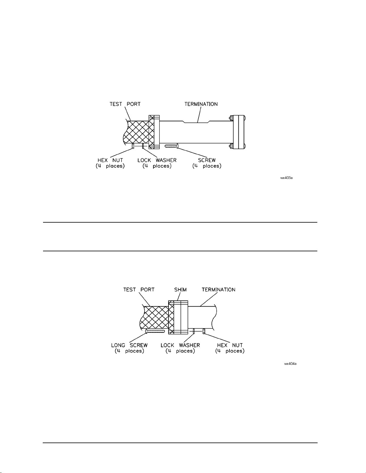
Load
Connect the termination to the appropriate test port, as shown in Figu re 3-3.
Figure 3-3 Test Port and Termination
Offset Load
Connect the shim and the termination to the appropriate test port, as shown in Figure 3-4
NOTE For offset load calib rat ion with the R 11644A WR -2 8, Q11644A WR-22, and
U11644A WR-19, the moving load must be in a locked position. For more
information refer to your network analyzer user’s guide.
Figure 3-4 Connect the Shim and the Termination to the Test Port
3-4 R, Q, U, V, and W11644A
Page 19
User Information
Measurement Applications
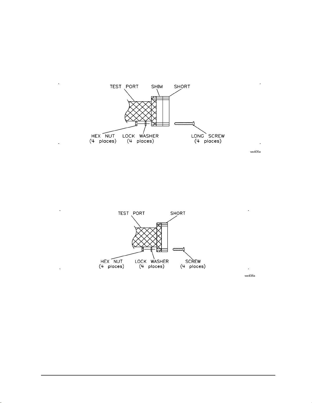
Offset Short
Connect the shim and the short to the appropriate test port, as shown in Figure 3- 5.
Figure 3-5 Connect th e Shim and the Short to the Test Port
Reflect
Connect the short to the appropriate test port, as shown in Figure 3-6.
Figure 3-6 Connect th e Short to the Test Port
Short
See “Reflect.”
R, Q, U, V, and W11644A 3-5
Page 20
User Information
Measurement Applications
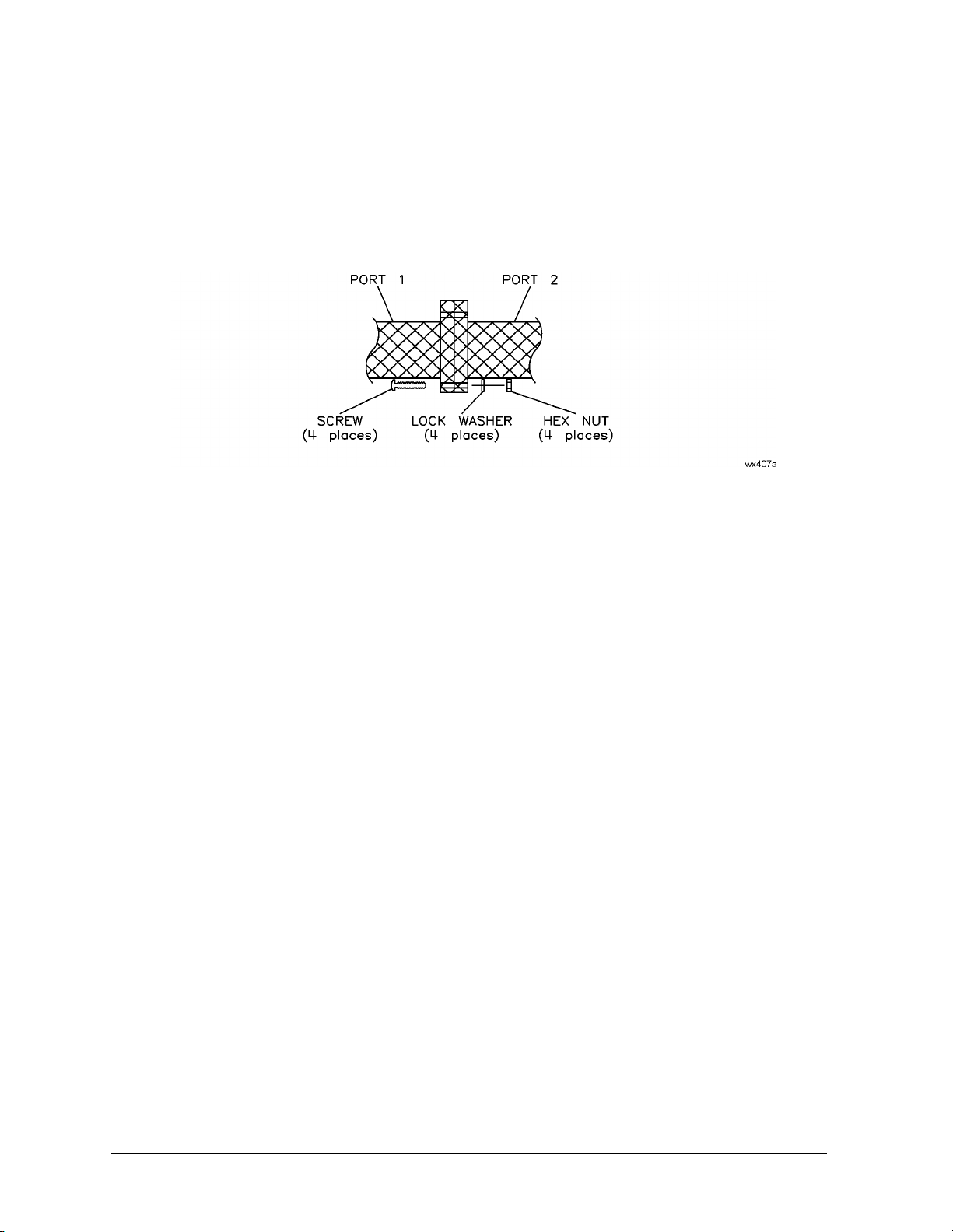
Thru
No device is required for this. Connect port 1 to port 2, as shown in Figure 3-7.
Figure 3-7 Co nnect Port 1 to Port 2
¼ Wavelength Load
See “Offset Load.”
¼ Wavelength Short
See “Offset Short.”
3-6 R, Q, U, V, and W11644A
Page 21

User Information
Changing the ¼ Wavelength Shim Calibration Definition
Changing the ¼ Wavelength Shim Calibration Definition
The calibration kit definition data provided with this kit has a nominal value for the ¼
wavelength shim offset delay. You may use the nominal value provided, or measure the
exact thickness of the shim and use that value to calculate its exact offset delay. Use the
following procedure to change the nomina l val ue of the ¼ wav eleng th s him dela y to ref lec t
the specific device in your kit.
1. Load the calibration kit data into Cal Kit 1.
2. Using the formula below, calculate the offset delay:
length of
----------------------------------------------------------------------------------------------------- offset delay (ns)=
299.6953
NOTE The value of the propagation velocity in air is corrected for a temperature of
23 °C, 50% relative humidity, and 760 mm Hg of pressure.
1
-- -wavelengh section (mm)
4
mm
-------- -(propagation velocity in air)
ns
R, Q, U, V, and W11644A 3-7
Page 22

User Information
Changing the ¼ Wavelength Shim Calibration Definition
3-8 R, Q, U, V, and W11644A
Page 23

4 Use, Maintenance, and Care of the
Devices
R, Q, U, V, and W11644A 4-1
Page 24
Use, Maintenance, and Care of the Devices
Electrostatic Discharge
Electrostatic Discharge
Protection against electrostatic discharge (ESD) is essential while connecting, inspecting,
or cleaning connectors attached to a static-sensitive circuit (such as those found in test
sets).
Static electricity can build up on your body and can easily damage sensitive internal
circuit elements when discharged. Static discharges too small to be felt can cause
permanent damage. Devices such as calibration c omponents and devices under test (DUT),
can also carry an electrostatic charge. To prevent damage to the test set, components, and
devices:
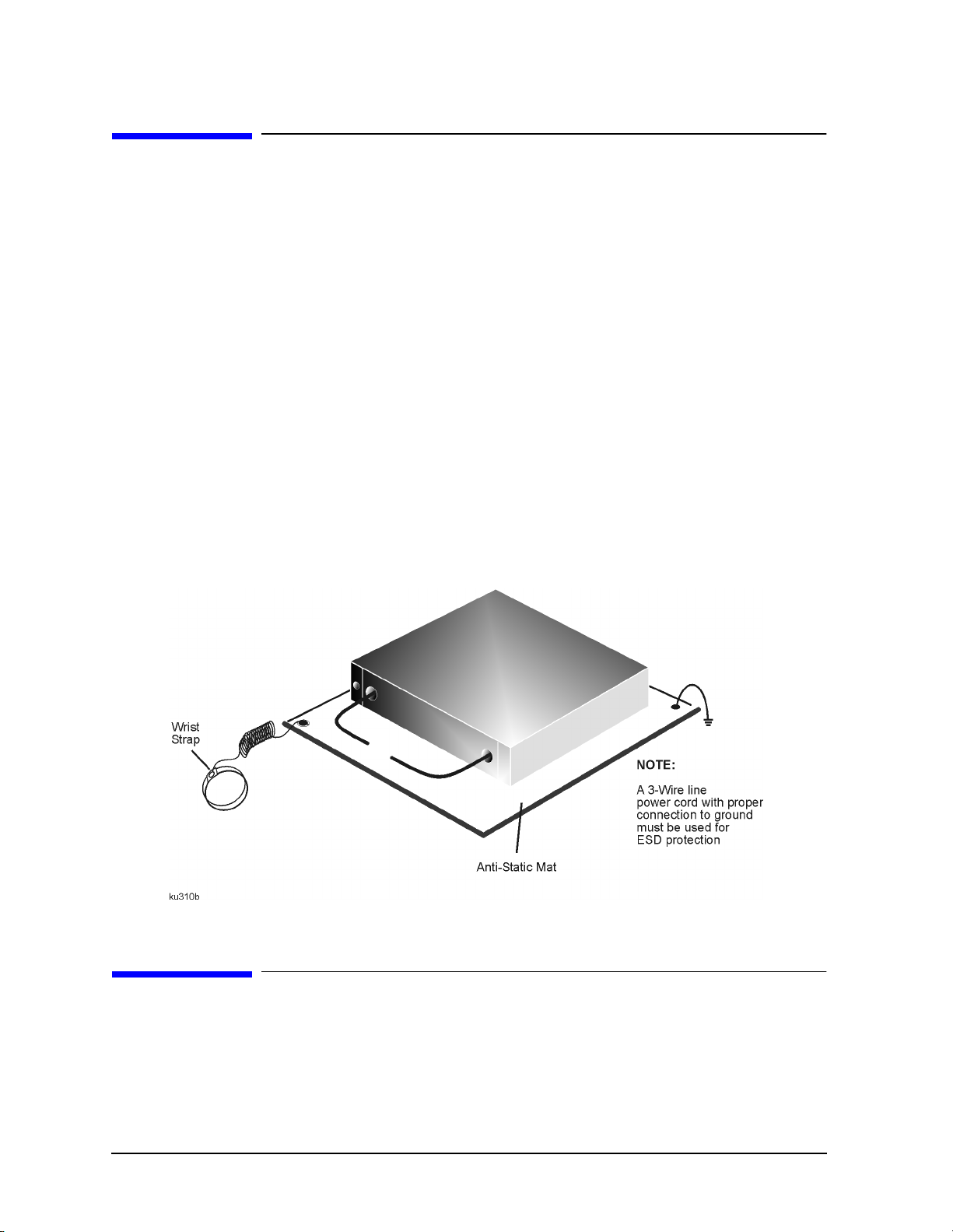
• Always wear a grounded wrist strap havi ng a 1 MΩ resistor in series with it when
handling components and devices or when making connections to the test set.
• Always use a grounded antistatic mat in front of your test equipment.
• Always wear a heel strap when working in an area with a conductive floor. If you are
uncertain about the conductivity of your floor, wear a heel strap.
Figure 4-1 shows a typical ESD protection setup using a grounded mat and wrist strap.
Refer to Table 7-6 o n page 7-14 for information on ordering supplies for ESD protection.
Figure 4-1 ESD Protection Setup
Visual Inspection
Visual inspection and, if necessary, cleaning should be done every time a connection is
made. Inspect mating surfaces for dirt, dust, foreign particles, or scratches, which can
degrade dev ice performance. A damaged mat ing surface ca n damage any go o d su rface
connected to it. If necessary, clean all mating surfaces.
4-2 R, Q, U, V, and W11644A
Page 25

Use, Maintenance, and Care of the Devices
Cleaning the Mating Plane Surfaces
Cleaning the Mating Plane Surfaces
1. Use Compressed Air or Nitrogen
WARNING Always use protective eyewear when using compressed air or
nitrogen.
Use compressed air (or nitrogen) to loose n particles on the mating plane su rfaces. Cl ean
air cannot damage a device or leave particles or residues behind.
You can use any source of clean, dry, low-pressure compressed air or nitrogen that has
an effective oil-vapor filter and liquid condensation trap placed just before the outlet
hose.
Ground the hose nozzle to prevent electrostatic discharge, and set the air pressure to
less than 414 kP a (6 0 psi) to c ontrol the v elocity of the air stream. High-veloci ty streams
of compressed air can cause electrostatic effects when directed into a device. These
electrostatic effects can damage the device. Refer to “Electro stati c Disc harge ” earlier in
this chapter for additional information.
WARNING Keep isopropyl alcohol away from heat, sparks, and flame. Store in a
tightly closed container. It is extremely flammable. In case of fire, use
alcohol foam, dry chemical, or carbon dioxide; water may be
ineffective.
Use isopropyl alcohol with adequate ventilation and avoid contact
with eyes, skin, and clothing. It causes skin irritation, may cause eye
damage, and is harmful if swallowed or inhaled. It may be harmful if
absorbed through the skin. Wash thoroughly after handling.
In case of spill, soak up with sand or earth. Flush spill area with
water.
Dispose of isopropyl alcohol in accordance with all applicable
federal, state, and local environmental regulations.
2. Clean the Mat ing Plane Surfaces
a. Apply a small amount of isopropyl alcohol to a lint-free cleaning swab.
b. Clean the mating plane surfaces.
c. Let the alcohol evaporate, then blow the mating plane surface dry with a gentle
stream of clean, low-pressure compressed air or nitrogen. Always completely dry a
device before you reassemble or use it.
3. Inspect
a. Inspect the mating plane surface to make sure that no particles or residue remain.
“Visual Inspection” on page 4-2.
R, Q, U, V, and W11644A 4-3
Page 26
Use, Maintenance, and Care of the Devices
Connections
Connections
Good connections requir e a skill ed op er ator. Slight errors i n oper ator technique can have a
significant effect on measurements and measurement uncertainties. The most common
cause of measurement error is poor connections.
The following procedures illustrate how to make good connections.
Waveguide Devices
IMPORTANT Unlike threaded devices, the WR-28, WR-22, WR-19, WR-15, and WR-10
waveguide mati ng planes ar e flanges (of ten precisi on) that you must carefull y
screw together. Always connect waveguide in the same flange orie ntation. F or
example, use the label as a reference and always connect a device with the
label facing the same direction.
Precision Flanges
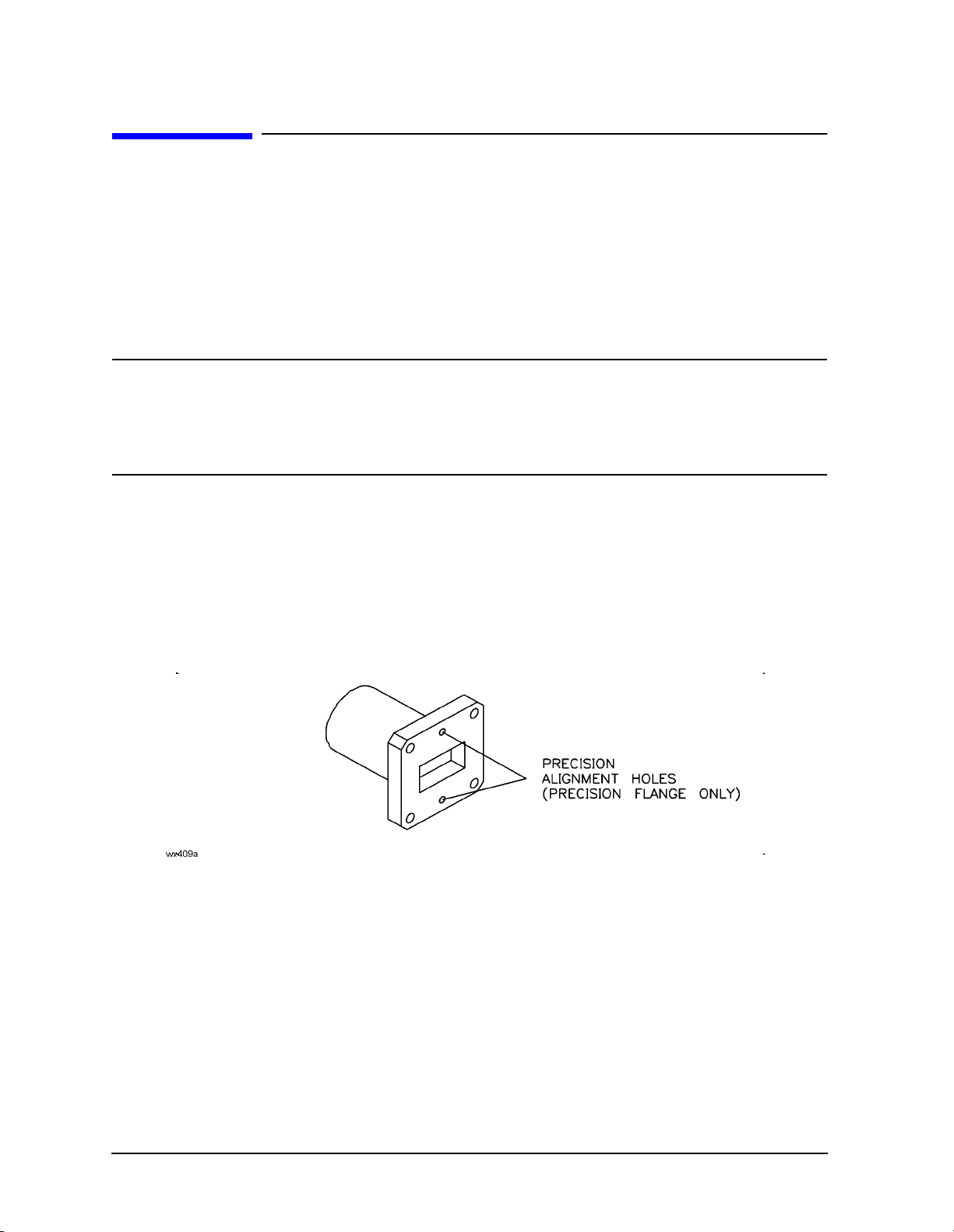
A precision flange has four corner screw holes and two precisi on alignment hole s, as s hown
in Figure 4- 2. A non-precision flange has only four corner screw holes.
Figure 4-2 Precis ion Alignment Holes
4-4 R, Q, U, V, and W11644A
Page 27
Use, Maintenance, and Care of the Devices
Connections
Aligning Two Precision Flanges
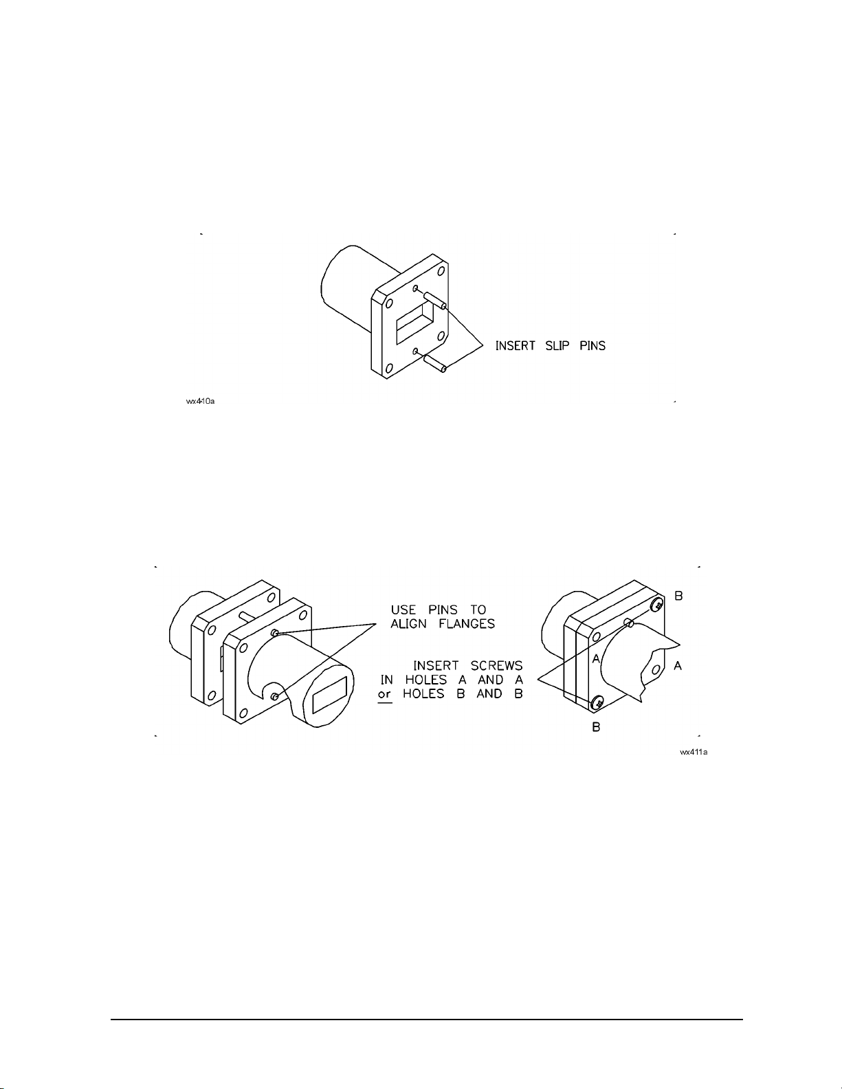
1. Place the slip pins in the top and bottom holes of one flange, as shown in Figure 4-3.
Figure 4-3 Inserting Slip Pins
2. Using the pins as guides, carefully align the flanges and insert two screws in the
diagonal corner holes, as shown in Figure 4-4.
Figure 4-4 Aligning Flanges
3. Place a lock washer and nut on each screw, and finger tighten.
4. Insert the remaining two screws.
5. Place a lock washer and nut on each screw, and finger tighten.
6. Remove the slip pins.
7. Go to “Tightening a Flange Connection” on page 4-7.
R, Q, U, V, and W11644A 4-5
Page 28
Use, Maintenance, and Care of the Devices
Connections
Aligning a Precision and a Non-Precision Flange
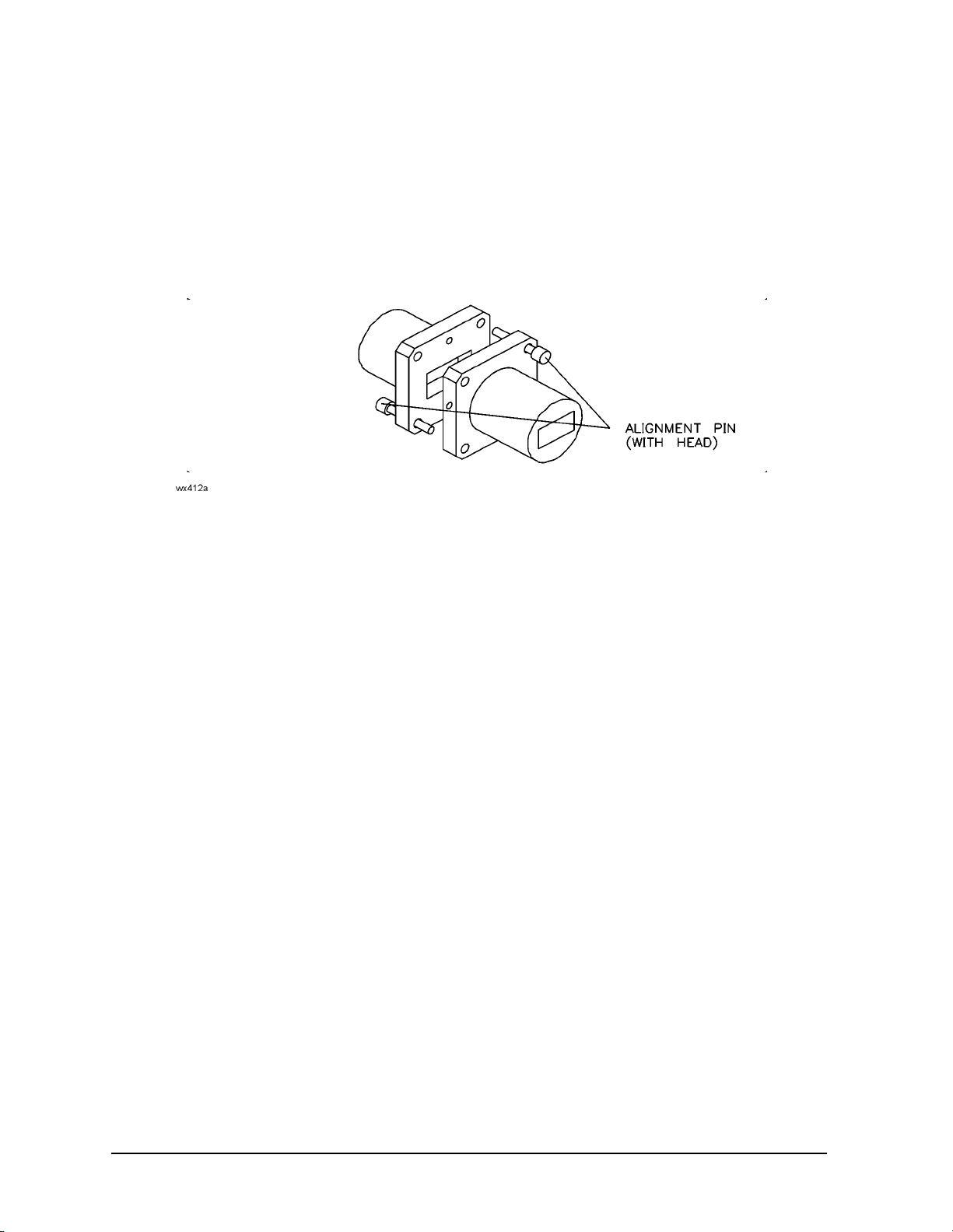
1. Place an alignment pin (with head) in the corner hole of one flange. Place a second
alignment pin in the diagonal corner hole of the second flange. See Figure 4-5 .
Figure 4-5 Aligning Pins
2. Using the pins as guides, carefully align the flanges and insert screws in the diagonal
corner holes.
3. Place a lock washer and nut on each screw, and finger tighten.
4. Remove the alignment pins and insert the remaining two screws.
5. Place a lock washer and nut on each screws, and finger tighten.
6. Go to “Tightening a Flange Connection” on page 4-7.
4-6 R, Q, U, V, and W11644A
Page 29
Use, Maintenance, and Care of the Devices
Connections
Tightening a Flange Connection
NOTE The best connection has symmetrical pressure applied as you gradually
tighten the screws.
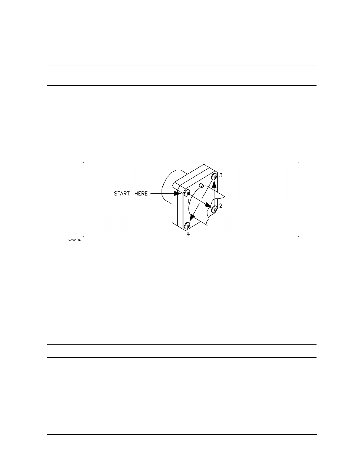
1. In an “X” pattern ( for equal compr ession), ti ghten all four screws using a hex ball drive r.
Do not over-tighten. See Figure 4-6 .
2. Visually inspect the connection. Refer to the following section “Inspecting a Flange
Connection.”
Figure 4-6 “X” Screw Pattern
Inspecting a Flange Connection
Inspect the flange connection as follows:
1. Place an electric light or white paper behind the connection.
2. Check the flange matings for any gap. A good connection has no gaps between the
connected waveguide flanges, and the waveguide walls are flush. There is no step or
offset.
3. Ensure that all four screws are equally tight.
NOTE The most common cause of measurement error is a poor connection.
R, Q, U, V, and W11644A 4-7
Page 30

Use, Maintenance, and Care of the Devices
Handling and Storage
Handling and Storage
• Install the protective end caps and store the calibration devices in the foam-lined
storage case when not in use.
• Never sto re de vices loose in a bo x, o r in a de sk or bench drawer. This is the most
common cause of device damage during storage.
• Keep devices clean.
• Do not touch mating plane surfaces. Natural skin oils and microscopic particles of dirt
are easily transferred to a device and are very difficult to remove.
• Do not set devices contact-end down on a hard surface. The plating and the mating
plane surfaces can be damaged if the interface comes in contact with any hard surface.
4-8 R, Q, U, V, and W11644A
Page 31

5 Performance Verification
R, Q, U, V, and W11644A 5-1
Page 32

Performance Verification
Introduction
Introduction
The performance of your calibra tion kit can only be verified by retur ning the kit to Agilent
Technologies for recertification. The equipment and calibration standards required to
verify the specifications of the limits of the devices in the kit have been specially
manufactured and are not commercially available. However, you may check the
performance of the terminations in this kit by following the procedure “Termination
Return Loss Measurement” on page 5-4.
To confirm that your calibration kit is performing accurate calibrations, use the
appropriate Agilent 11645A verification kit with the “Specificatio ns & Per formanc e
Verification” disk included in this kit.
How Agilent Verifies the Devices in Your Kit
Agilent verifies the specifications of these devices as follows:
1. The residual microwave error terms of the test system are verified with precision
airlines and shorts that are directly traced to the National Institute of Standards and
Tec hnology (NIST). The airline and short characteristics are developed from mechanical
measurements. The mechanical measurements and material properties are carefully
modeled to give very accurate electrical representa tion. The mechanical measurements
are then traced to NIST through various plug and ring gages and other mechanical
measurements.
2. Each calibration device is electrically tested on this system. For the initial (before sale)
testing of the ca li brat ion de vi ces , Agilent includes the test measurement uncer tainty a s
a guardband to guarantee each device meets the published specification. For
recertifications (after sale), no guardband is used and the measured data is compared
directly with the specification to determine the pass or fail status. The measurement
uncertainty for each device is, however, recorded in the calibration report that
accompanies recertified kits.
These two steps establish a traceable link to NIST for Agilent to the extent allowed by the
institute’s calibration facility. The specifications data provided for the devices in the kit is
traceable to NIST through Agilent Technologies.
5-2 R, Q, U, V, and W11644A
Page 33

Performance Verification
Recertification
Recertific at ion
The following will be provided with a recertified kit:
• a new calibration sticker affixed to the case
• a certificate of calibration
• a calibration report for each device in the kit listing measured values, specifications,
and uncertainties
NOTE A list of NIST traceable numbers may be purchased upon request to be
included in the calibration report.
Agilent Technologies offers a Standard calibration for the recertification of the kit. For
more information, contact Agilent Technologies. Refer to “Contacting Agilent” on page 6-4
for a lis t o f o ffices.
How Often to Recertify
The suggested initial inter val fo r recertifi cation i s 12 months or sooner. The actual need for
recertification depends on the use of the kit. After reviewing the results of the initial
recertification, you may establi sh a different recertif ication inter val that reflects the usage
and wear of the kit.
NOTE The recertification interva l should begin on the date the kit is first used after
the recertification date.
Where to Send a Kit for Recertification
Contact Agilent Technologies for information on where to send your kit for recertification.
Contact information is listed on page 6-4. Refer to “Returning a Kit or Device to Agilent”
on page 6-4 for details on sending your kit.
R, Q, U, V, and W11644A 5-3
Page 34
Performance Verification
Performance Test
Performance Test
Termination Return Loss Measurement
Use this test to check the performance of the terminations in this kit.
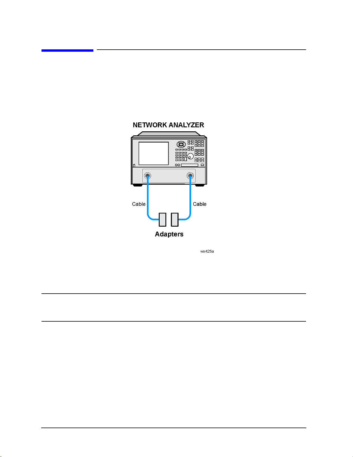
Figure 5-1 Return Loss Test Se tup
1. Connect the equipment as shown in Figure 5-1. Turn on and preset the network
analyzer. Let the equipment warm up for at least one hour.
NOTE The calibration kit definitions must already be loaded in the analyzer. Refer
to your analyzer user’s guide for information on how to load the calibration
kit definitions.
2. Set the appropriate start frequency to:
• 26.5 GHz (R-band)
• 33 GH z (Q-band)
• 40 GHz (U-band)
• 50 GH z (V-band)
• 75 GHz (W-band)
5-4 R, Q, U, V, and W11644A
Page 35
3. Set the appropriate stop frequency to:
• 40 GH z (R -band)
• 50 GH z (Q-band)
• 60 GHz (U-band)
• 75 GH z (V-band)
• 110 GHz (W-band)
4. Set the averaging factor to 512.
5. At the adapter test port, perform a 2–port TRL calibration.
6. Turn on the calibration.
7. Connect the termination you wish to test to port 1.
Performance Verification
Performance Test
8. Measure the return loss (S
) of the load.
11
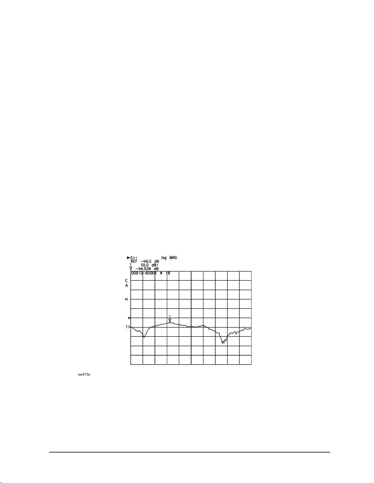
9. After one complete measurement sweep, the displayed trace should look similar to that
shown in Figure 5-2.
10.If necessary, update the trace.
11.Use a marker to determine the maximum value on the trace. This marker determines
worst -case re turn los s.
Figure 5-2 Typical Termination Return Loss
In Case of Failu re
If a termination fails this test, clean all flanges and caref ully reconnect the devices . Repeat
the test. If the termination fails again, replace it. Refer to Table 2-2, “Electrical
Characteristics and Specifications,” on page 2-3.
R, Q, U, V, and W11644A 5-5
Page 36

Performance Verification
Performance Test
5-6 R, Q, U, V, and W11644A
Page 37

6 Troubleshooting
R, Q, U, V, and W11644A 6-1
Page 38

Troubleshooting
Troubleshooting Process
Troubleshooting Process
This manual contains limited information about network analyzer system operation. For
complete information, refer to the instrument documentation.
If you suspect a bad calibration, or if your network analyzer does not pass performance
verification, follow the steps in Figure 6-1.
6-2 R, Q, U, V, and W11644A
Page 39
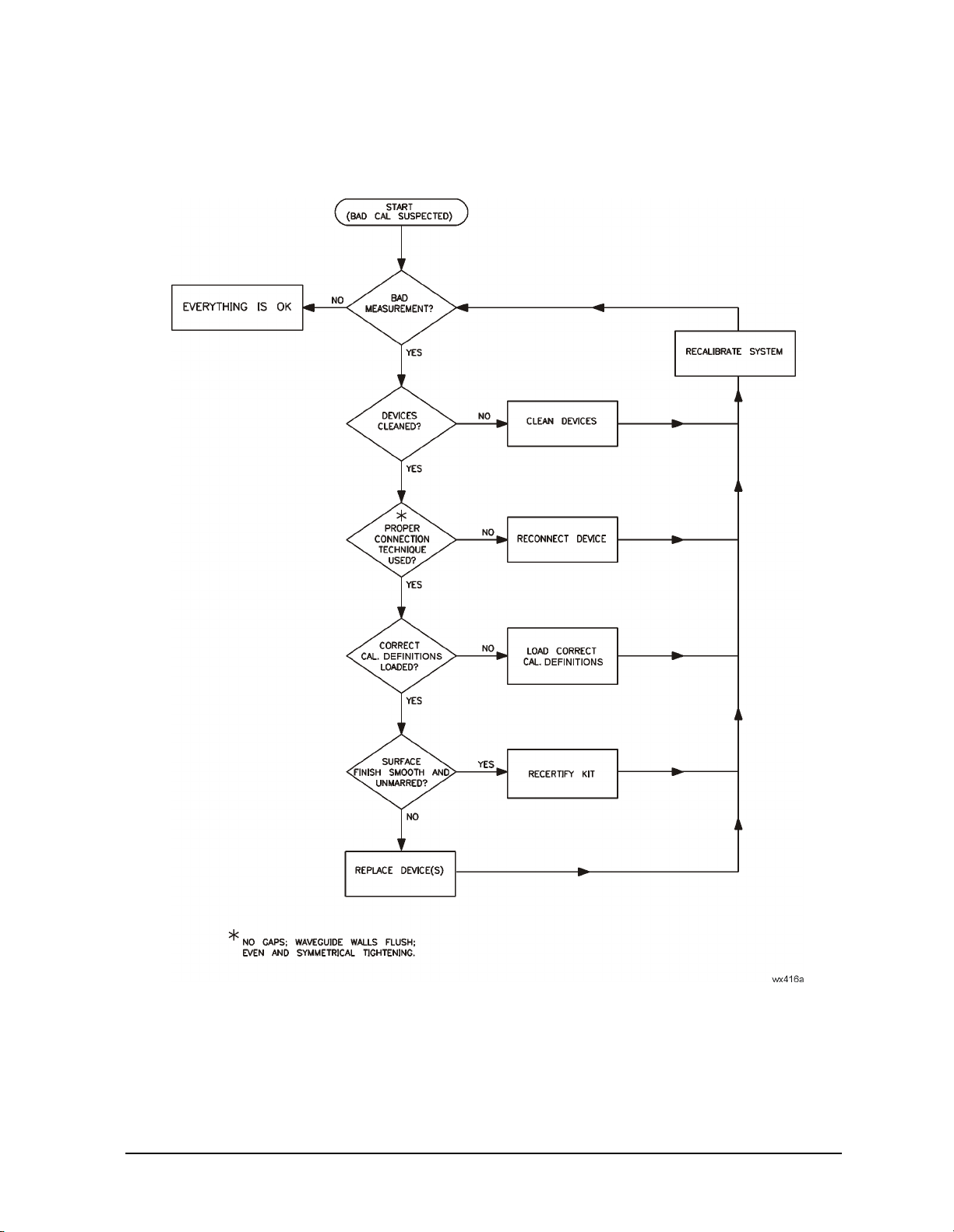
Figure 6-1 Troubleshooting Flowchart
Troubleshooting
Troubleshooting Process
R, Q, U, V, and W11644A 6-3
Page 40
Troubleshooting
Returning a Kit or Device to Agilent
Returning a Kit or Device to Agilent
If your kit or device requires service, contact Agilent Technologies for information on
where to send it. See Table 6-1 for contact information. Include a service tag (located near
the end of this manual) on which you provide the following information:
• your company name and address
• a technical contact person within your company, and the person's complete telephone
number
• the model number and serial number of the kit
• the part number and serial number of each device
• the type of service required
•a detailed description of the problem and how the device was being used when the
problem occurred (such as calibration or measurement)
Where to Look for More Information
This manual contains limited information about network analyzer system operation. For
complete information, refer to the instrument documentation. If you need additional
information, contact Agilent Technologies.
Contacting Agilent
Table 6-1 Contacting Ag ilent
Online assistance: www.agilent.com/find/assist
United States
(tel) 1 800 452 4844
New Zealand
(tel) 0 800 738 378
(fax) (+64) 4 495 8950
Malaysia
(tel) 1 800 828 848
(fax) 1 800 801 664
Latin America
(tel) (305) 269 7500
(fax) (305) 269 7599
Japan
(tel) (+81) 426 56 7832
(fax) (+81) 426 56 7840
Philippines
(tel) (632) 8426802
(tel) (
PLDT subscriber only):
1 800 16510170
(fax) (632) 8426809
(fax) (
PLDT subscriber only):
1 800 16510288
Canada
(tel) 1 877 894 4414
(fax) (905) 282-6495
Australia
(tel) 1 800 629 485
(fax) (+61) 3 9210 5947
Thailand
(tel) outside Bangko k:
(088) 226 008
(tel) with in Bangkok :
(662) 661 3999
(fax) (66) 1 661 3714
Europe
(tel) (+31) 20 547 2323
(fax) (+31) 20 547 2390
Singapore
(tel) 1 800 375 8100
(fax) (65) 836 0252
Hong Kong
(tel) 800 930 871
(fax) (852) 2506 9233
Taiwan
(tel) 0800-047-866
(fax) (886) 2
25456723
Pe opl e’s Republic of
China
(tel) (preferred):
800-810-0189
(tel) (alternate):
10800-650-0021
(fax) 10800-650-0121
India
(tel) 1-600-11-2929
(fax) 000-800-650-1101
6-4 R, Q, U, V, and W11644A
Page 41

7 Replaceable Parts
R, Q, U, V, and W11644A 7-1
Page 42

Replaceable Parts
This page is intent ionally left blan k .
7-2 R, Q, U, V, and W1 1644A
Page 43

Replaceable Parts
Introduction
Introduction
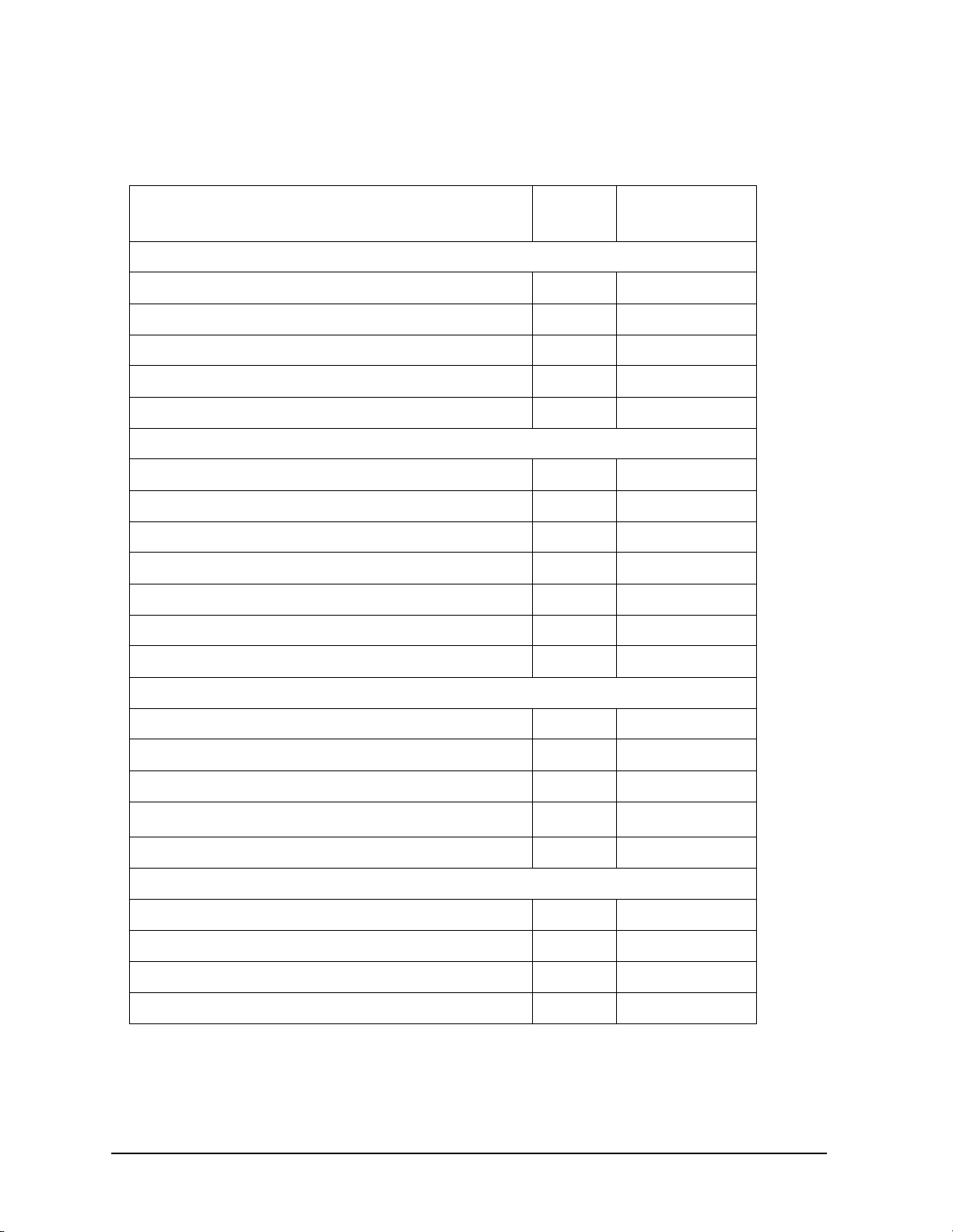
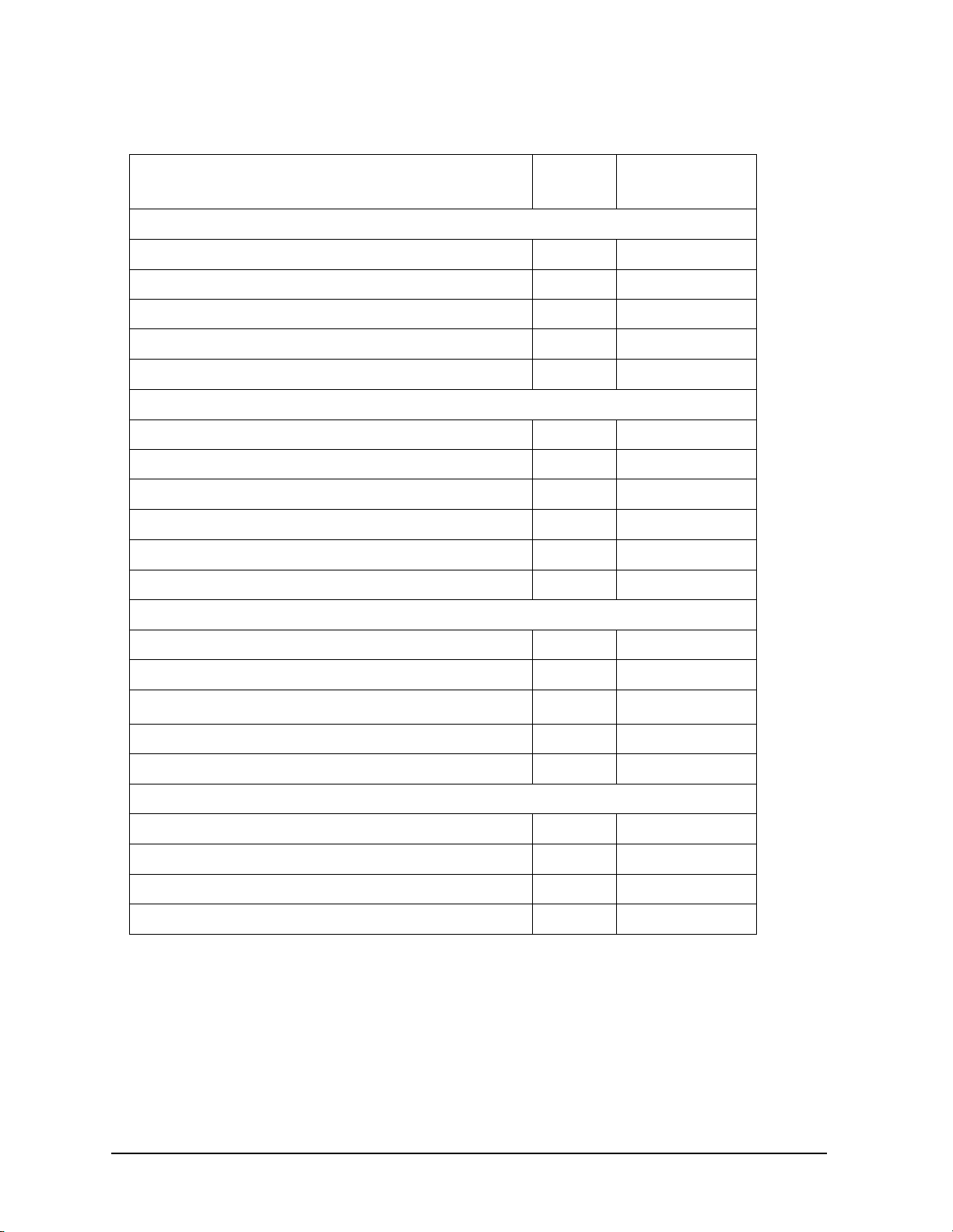
The following tables list the replacement part numbers for the Agilent R, Q, U, V, and
W116 44A wav eg u ide calibrat io n kits. Table 7-6 lists the replacement part numbers for
items not included in the calibration kit that are either required or recommended for
successful operation of this kit.
To order a listed part, note the description, part number, and the quantity desired.
Telephone or send your order to Agilent Technologies. Refer to “Contacting Agilent” on
page 6-4 for furt h er informa ti o n .
R, Q, U, V, and W11644A 7-3
Page 44
Replaceable Parts
Introduction
Table 7-1 Replacea ble Parts for the R1164 4A WR-28
Description Qty
Per Kit
Agilent
Part Number
Calibration Devices
Straight section (5 cm) 2 11644-60016
Standard section (10 cm) 1 11644-60001
Waveguide load 1 11644-60004
Short 1 11644-20005
Shim 1 11644-20003
Hardware
Alignment pin 6 11644-20009
Slip pin (2.367 mm diameter) 6 11644-20006
4-40 Hex nut (0.094 inch) 12 2260-0002
4-40 SKT HD screw (0.750 inch) 12 3030-0721
Lock washer (0.115 inch) 12 2190-0030
Open end wrench 1 8720-0013
Hex ball driver 1 8710-0523
Miscellaneous Items
User’s and service guide 1 11644-90369
Calibration definitions disk (R) 1 11644-10012
Calibration definitions disk (PNA) 1 11644-10020
Specificati on s and perf orman ce veri fi cat i on disk
a
1 08510-10033
Connector care quick-reference card 1 08510-90360
Calibr ation Kit Storage Case
Storage case 1 5181-5517
Box 2 1540-0034
Foam pad (set) 1 11644-80040
Disk holder 1 5180-8491
a. See the 8510C On-Site Service Manual for instructions on using this disk.
7-4 R, Q, U, V, and W1 1644A
Page 45
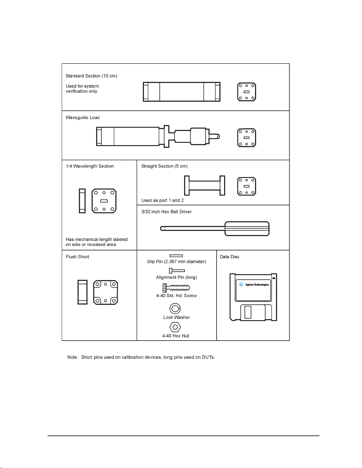
Figure 7-1 R-Band Component Identification Sheet
Replaceable Parts
Introduction
R, Q, U, V, and W11644A 7-5
Page 46
Replaceable Parts
Introduction
Table 7-2 Replaceable Parts for the Q11644A WR-22
Description Qty
Per Kit
Agilent Part
Number
Calibration Devices
Straight section (5 cm) 2 11644-60017
Standard section (10 cm) 1 11644-60002
Waveguide load 1 11644-60005
Shim 1 11644-20001
Short 1 11644-20004
Hardware
Slip pin (1.645 mm diameter) 6 11644-20008
Slip pin (2.367 mm diameter) 6 11644-20006
4-40 captive screw (0.31 inches long) 24 1390-0671
4-40 captive screw (0.43 inches long) 12 1390-0764
4-40 SKT HD screw (0.50 inches long) 12 3030-0203
Hex ball driver 1 8710-0523
Miscellaneous Items
Calibration definitions disk (Q-band) 1 11644-10013
Calibration definitions disk (PNA) 1 11644-10019
Specificati on s and perf orman ce veri fi cat i on disk
a
1 08510-10033
User’s and service guide 1 11644-90369
Connector care-quick reference card 1 08510-90360
Calibr ation Kit Storage Case
Storage case 1 5181-5517
Box 2 1540-0034
Foam pad (set) 1 11644-80041
Disk holder 1 5180-8491
a. See the 8510C On-Site Service Manual for instructions on using this disk.
7-6 R, Q, U, V, and W1 1644A
Page 47
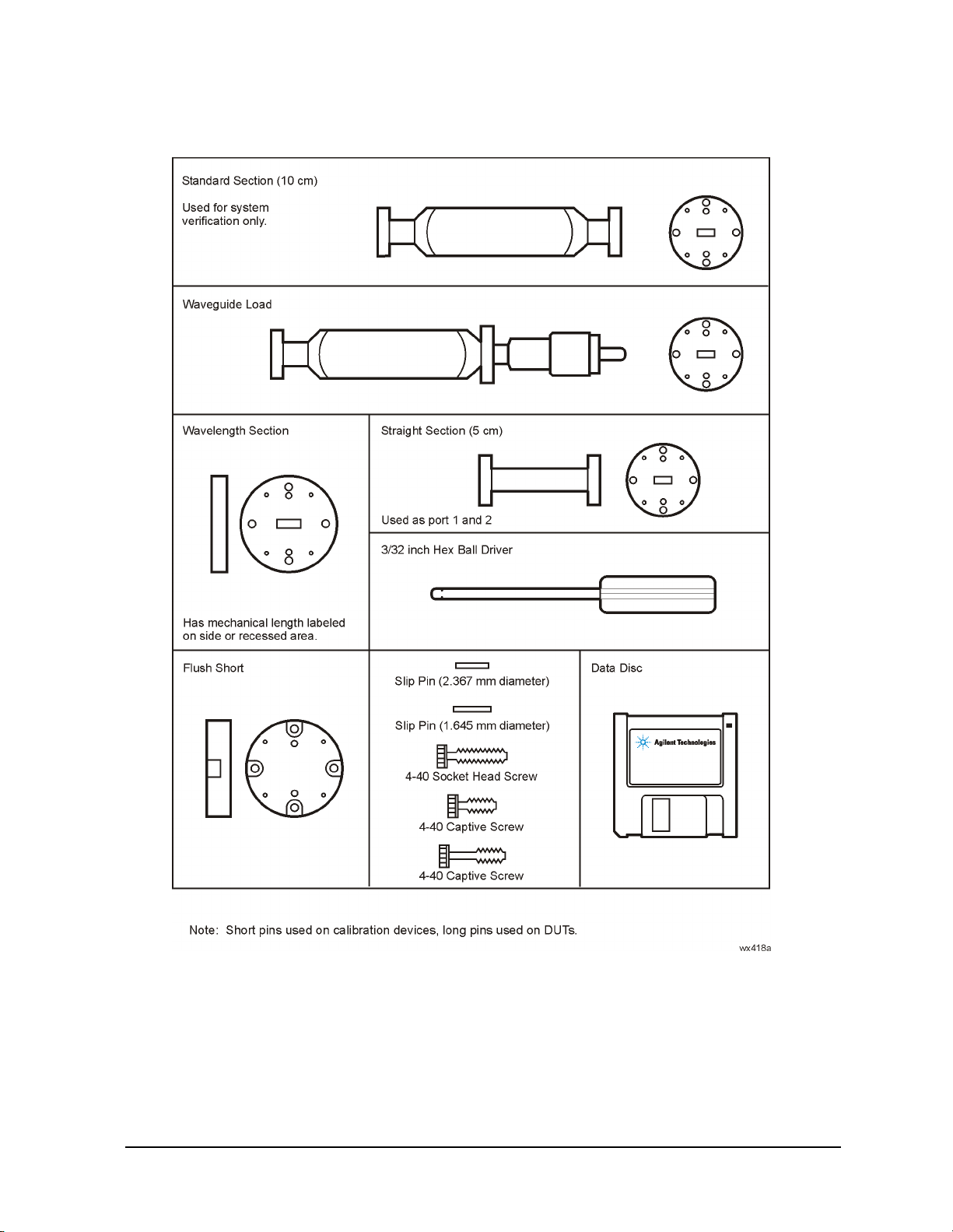
Figure 7-2 Q-Band Component Id entification Sheet
Replaceable Parts
Introduction
R, Q, U, V, and W11644A 7-7
Page 48
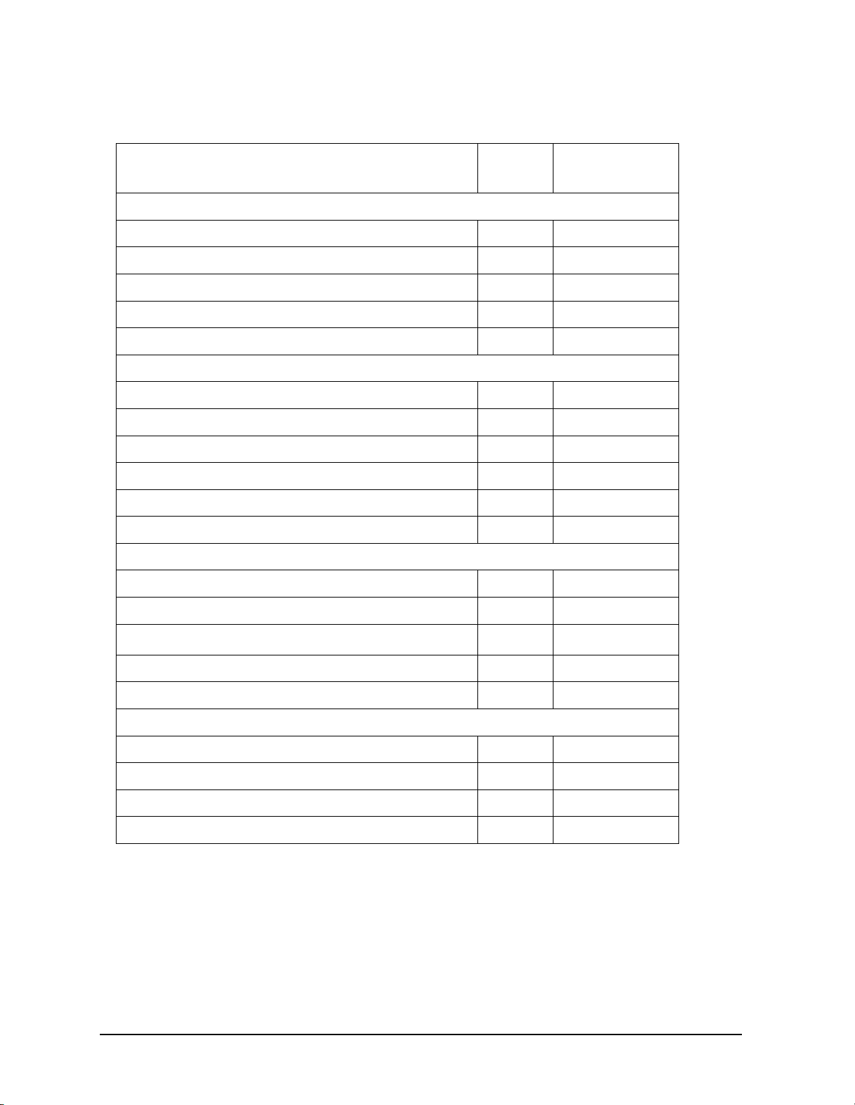
Replaceable Parts
Introduction
Table 7-3 Replaceable Parts for the U11644A WR-19
Description Qty
Per Kit
Agilent Part
Number
Calibration Devices
Straight section (5 cm) 2 11644-60018
Standard section (10 cm) 1 11644-60003
Waveguide load 1 11644-60006
Shim 1 11644-20002
Short 1 11644-20004
Hardware
Slip pin (1.645 mm diameter) 6 11644-20008
Slip pin (2.367 mm diameter) 6 11644-20006
4-40 captive screw (0.31 inches long) 24 1390-0671
4-40 captive screw (0.43 inches long) 12 1390-0764
4-40 SKT HD screw (0.50 inches long) 12 3030-0203
Hex ball driver 1 8710-0523
Miscellaneous Items
Calibration definitions disk (U-band) 1 11644-10014
Calibration definitions disk (PNA) 1 11644-10019
Specificati on s and perf orman ce veri fi cat i on disk
a
1 08510-10033
User’s and service guide 1 11644-90369
Connector care-quick reference card 1 08510-90360
Calibr ation Kit Storage Case
Storage case 1 5181-5517
Box 2 1540-0034
Foam pad (set) 1 11644-80041
Disk holder 1 5180-8491
a. See the 8510C On-Site Service Manual for instructions on using this disk.
7-8 R, Q, U, V, and W1 1644A
Page 49
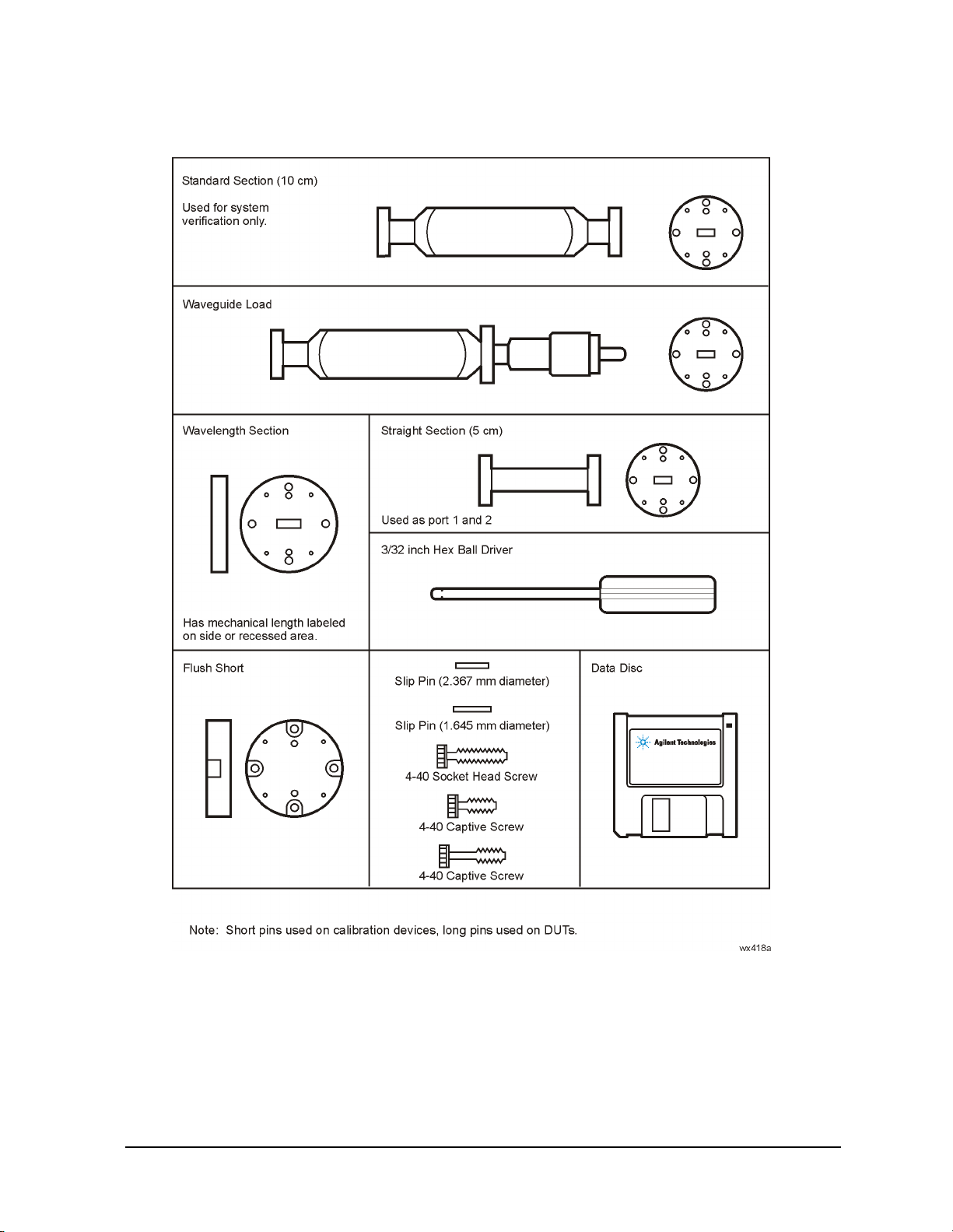
Figure 7-3 U-Band Component Id entification Sheet
Replaceable Parts
Introduction
R, Q, U, V, and W11644A 7-9
Page 50
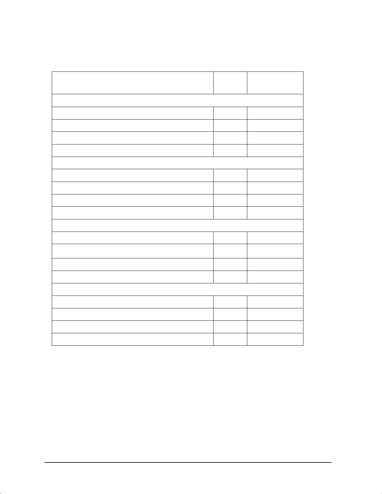
Replaceable Parts
Introduction
Table 7-4 Replacea ble Parts for the V11644A WR-15
Description Qty
Per Kit
Agilent
Part Number
Calibration Devices
Fixed load 1 11644-60025
Standard section (5 cm) 3 11644-60012
Shim 1 11644-20013
Short 1 11644-20015
Hardware
Slip pin (1.567 mm diameter) 6 11644-20007
4-40 captive screw (0.41 inch) 12 1390-0765
4-40 captive screw (0.31 inch) 24 1390-0671
Hex ball driver 1 8710-0523
Miscellaneous Items
Calibration definitions disk (V-band) 1 11644 -10015
Specificati on s and perf orman ce veri fi cat i on disk
a
1 08510-10033
User’s and service guide 1 11644-90369
Connector care-quick reference card 1 08510-90360
Calibr ation Kit Storage Case
Storage case 1 5181-5517
Box 2 1540-0034
Foam pad (set) 1 11644-80042
Disk holder 1 5180-8491
a. See the 8510C On-Site Service Manual for instructions on using this disk.
7-10 R, Q, U, V, and W11644A
Page 51
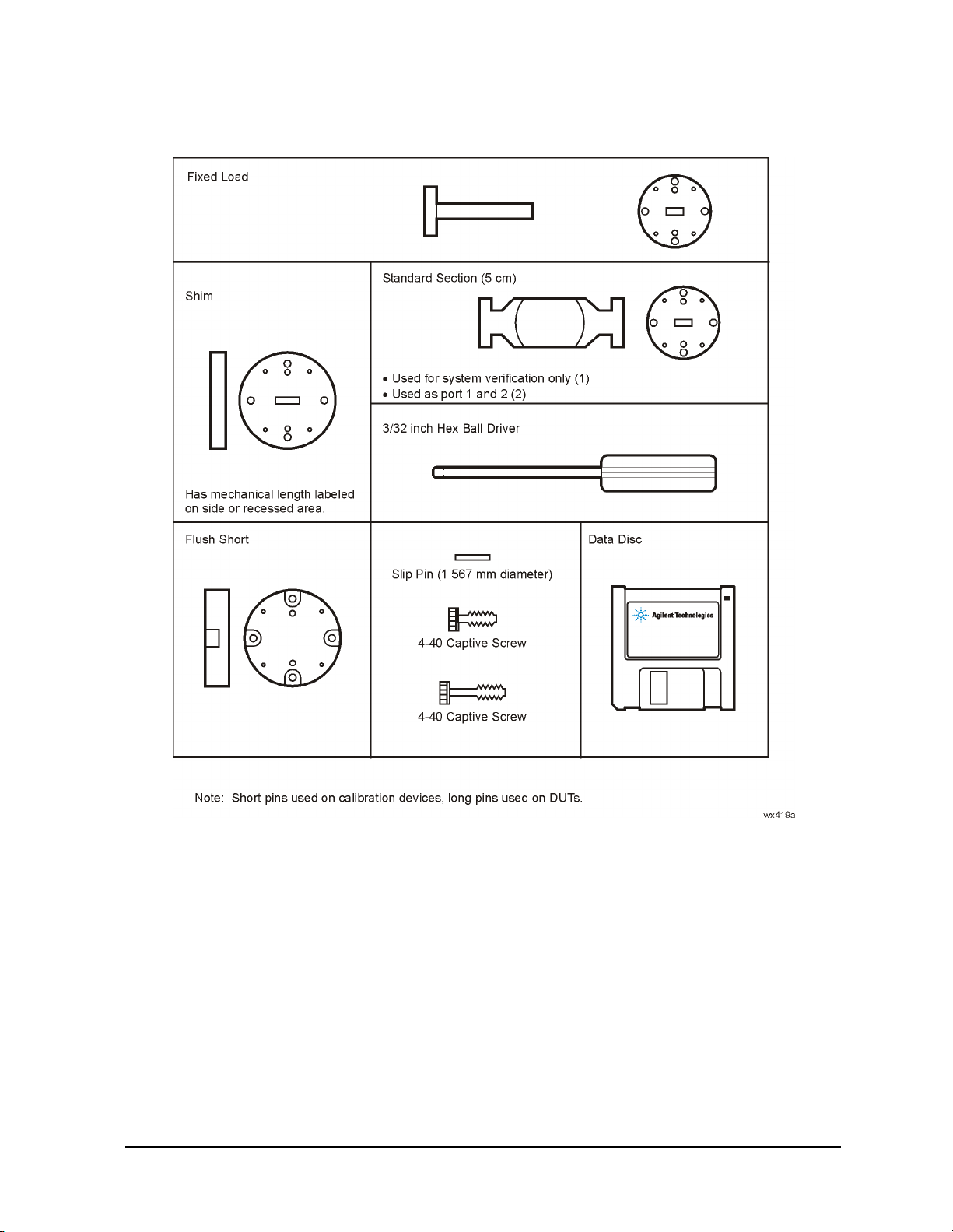
Figure 7-4 V-Band Component Identification Sheet
Replaceable Parts
Introduction
R, Q, U, V, and W11644A 7-11
Page 52
Replaceable Parts
Introduction
Table 7-5 Replaceable Parts for the W11644A WR-10
Description Qty
Per Kit
Agilent
Part Number
Calibration Devices
Fixed load 1 11643-60026
Standard section 3 11644-60013
Shim 1 11644-20014
Short 1 11644-20015
Hardware
Slip pin (1.567 mm diameter) 6 11644-20007
4-40 captive screw (0.41 inch) 12 1390-0765
4-40 captive screw (0.31 inch) 24 1390-0671
Hex ball driver 1 8710-0523
Miscellaneous Items
Calibration definitions disk (W-band) 1 11644-10016
Specificati on s and perf orman ce veri fi cat i on disk
a
1 08510-10033
User’s and service guide 1 11644-90369
Connector care-quick reference card 1 08510-90360
Calibr ation Kit Storage Case
Storage case 1 5181-5517
Box 2 1540-0034
Foam pad (set) 1 11644-80042
Disk holder 1 5180-8491
a. See the 8510C On-Site Service Manual for instructions on using this disk.
7-12 R, Q, U, V, and W11644A
Page 53

Figure 7-5 W-Band Component Identification Sheet
Replaceable Parts
Introduction
R, Q, U, V, and W11644A 7-13
Page 54
Replaceable Parts
Introduction
Table 7-6 Items Not Included in the Calibration Kit
Description Qty Agilent
Part Number
ESD Protection Devices
Grounding wrist str ap 1 9300-1367
5 ft grounding cord for wrist strap 1 9300-0980
2 ft by 4 ft conductive table mat with 15 ft ground in g
wire
ESD heel strap 1 9300-1308
Cleaning Supplies
Isopropyl alcohol 30 ml 8500-5344
Foam-tipped cleaning swabs 100 9301-1243
1 9300-0797
7-14 R, Q, U, V, and W11644A
Page 55

A Standard Definitions
R, Q, U, V, and W11644A A-1
Page 56
Standard Definitions
Standard Class Assignments
Standard C l ass Assignment s
Class assignment organizes calibration standards into a format compatible with the error
models used in the measu rement c alibration. A class or g rou p of c las se s corr es po nds t o the
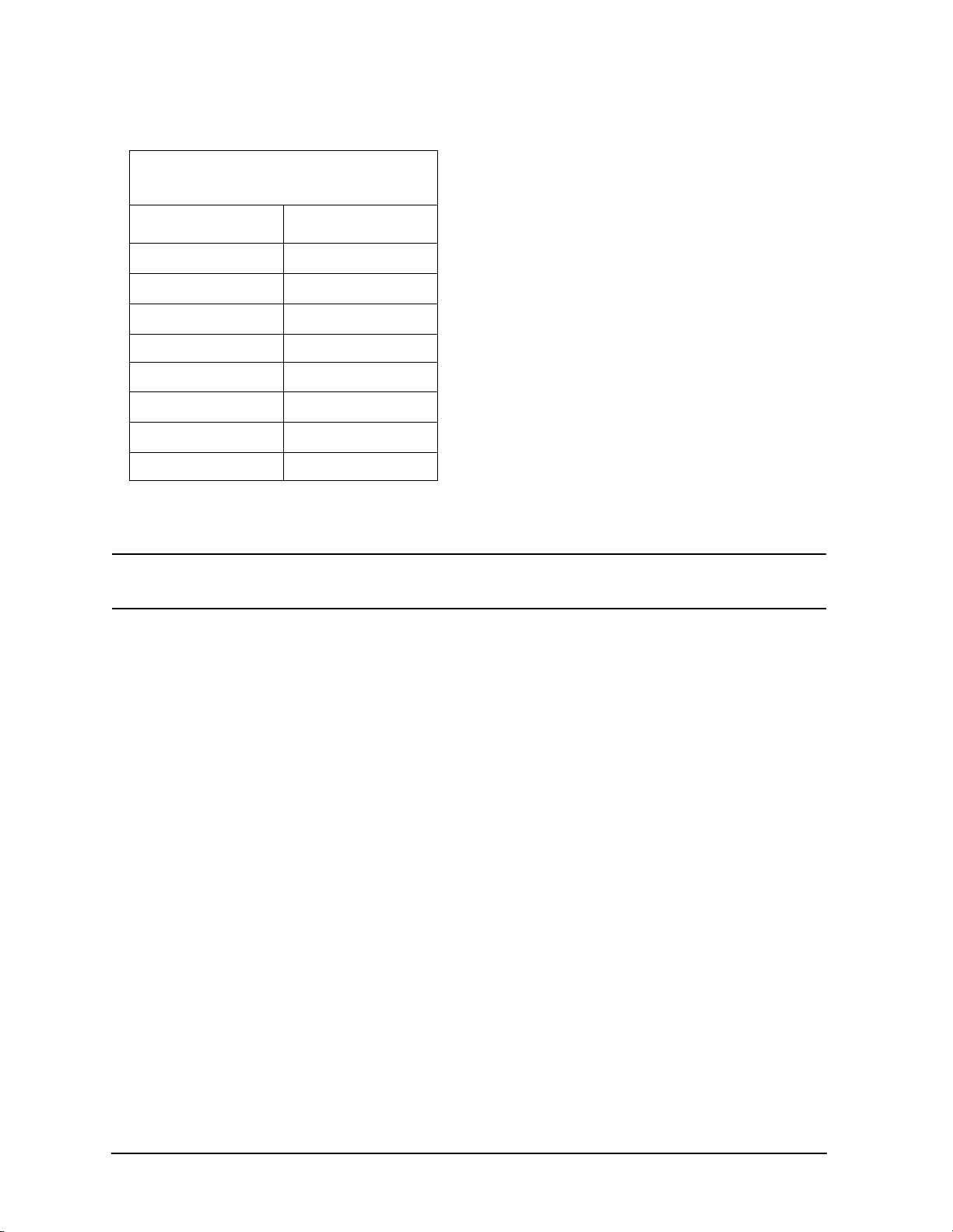
systematic errors to be removed from the measured network analyzer response. T ables A-1
through A-3 list the classes of the devices in the kit for the 8510 and PNA series
respectively. This information resides on the calibration definitions disks included in the
kit. Some network analyzers have the information stored in memory.
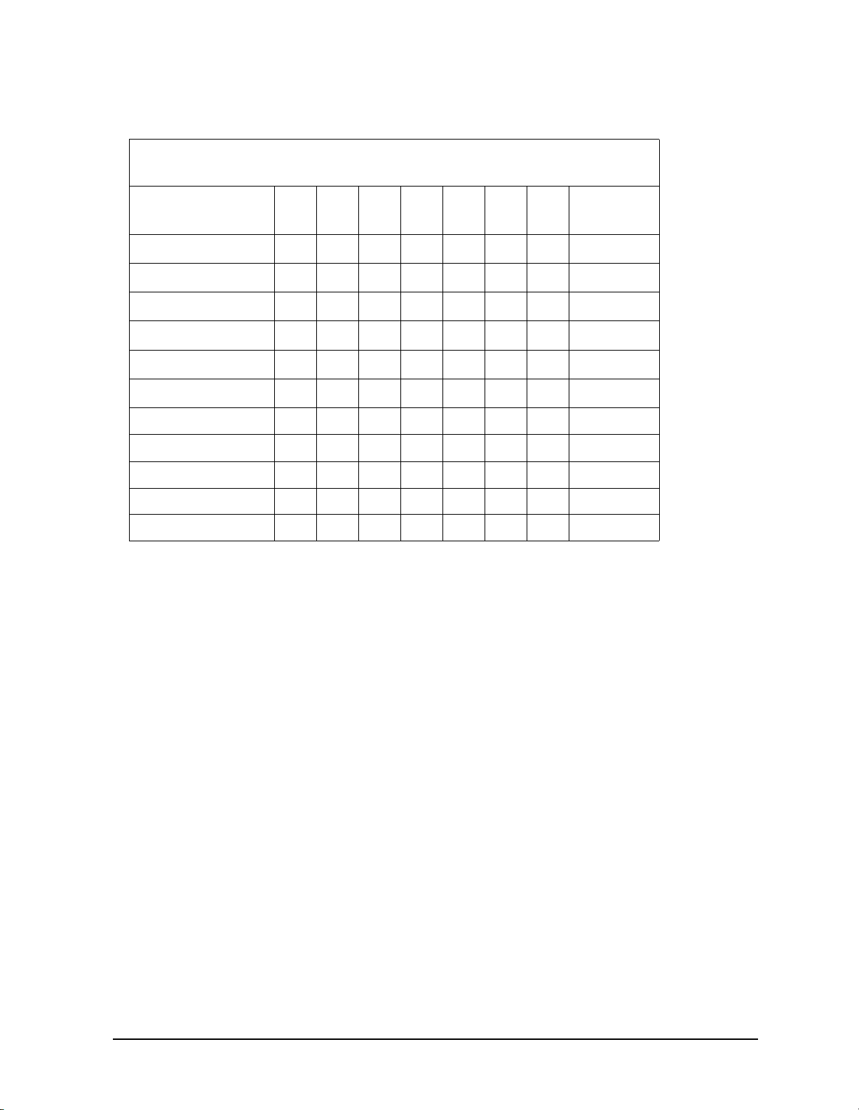
Table A-1 Standard Class Assignments for the 8510 (WR-19, WR-22,
and WR- 28)
Disk File Name: CK_WR-28 , or CK_WR-22,
or CK_WR-19
Class A B C D E F G Standard
S
A1 Short
11
S
B3 Offset
11
S
C 9 10 20 Loads
11
S
A1 Short
22
S
B3 Offset
22
S
C 9 10 20 Loads
22
Forward transmission 11 Thru
Reverse transmission 11 Thru
For ward ma tch 11 T hr u
Reverse match 11 Thru
Frequency res ponse 1 11 Response
Calibration Kit Label: WR- 28 A.2,
or WR-22 A.2, or WR-19 A.2
Class Label
A-2 R, Q, U, V, and W11644A
Page 57
Standard Definitions
Standard Class Assignments
Table A-2 Standard Class Assignments for the 8510 (WR-10 and WR-15)
Disk File Name: CK_WR-15, or CK_WR-10 Calibration Kit Label: WR-15 A.2,
or WR-10 A.2
Class A B C D E F G Standard
Class Label
S
A1 Short
11
S
B3 Offset
11
S
C 9 20 Loads
11
S
A1 Short
22
S
B3 Offset
22
S
C 9 20 Loads
22
For w ard transmissio n 11 Thru
Reve rse transmission 11 Thru
Forward match 11 Thru
Reverse match 11 Thru
Frequency response 1 11 Response
R, Q, U, V, and W11644A A-3
Page 58
Standard Definitions
Standard Class Assignments
Table A-3 Standard Class Assignments for the PNA Series Network Analyzer
Calibration Kit Label:
PNA Series
Class
S11A1
S
B2
11
S
C 3, 4, 5
11
Fo rward transmission 6, 7, 8
S
A1
22
S
B2
22
S
C 3, 4, 5
22
Isolation 3, 4, 5
a. For additional ports, make sure values
match the correct sex of the port.
A
a
IMPORTANT The following calibrations are only supported by certain PNA analyzers. See
your PNA network analyzer embedded help system.
Notes:
1. If you are performing a TRL calibration:
•S
•S
•S
T and S12T must be def ine d as thru standards .
21
A and S22A must be defined as reflection standards.
11
B, S11C, S22B, and S22C must be defined as line standards.
11
2. If you are performing a TRM calibration:
•S
•S
•S
T and S12T must be def ine d as thru standards .
21
A and S22A must be defined as reflection standards.
11
B, S11C, S22B, and S22C must be defined as match standar d s.
11
3. If you are performing an LRM calibration:
•S
•S
•S
4. S
5. S
T and S12T must be def ine d as line standard s.
21
A and S22A must be defined as reflection standards.
11
B, S11C, S22B, and S22C must be defined as match standar d s.
11
B and S11C must be defined as the same standard.
11
B and S22C must be defined as the same standard.
22
A-4 R, Q, U, V, and W11644A
Page 59
Standard Definitions
Standard Class Assignments
Blank Forms
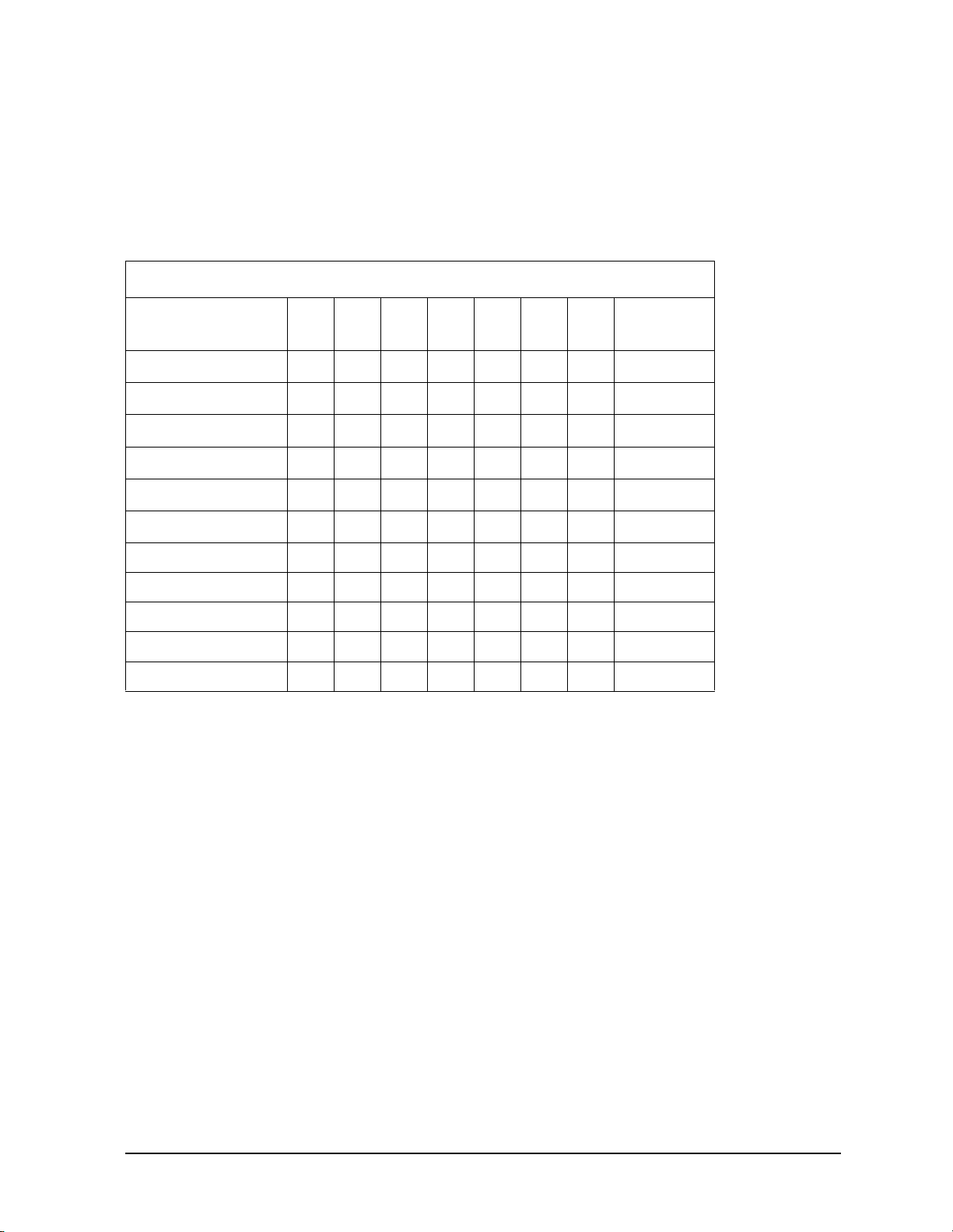
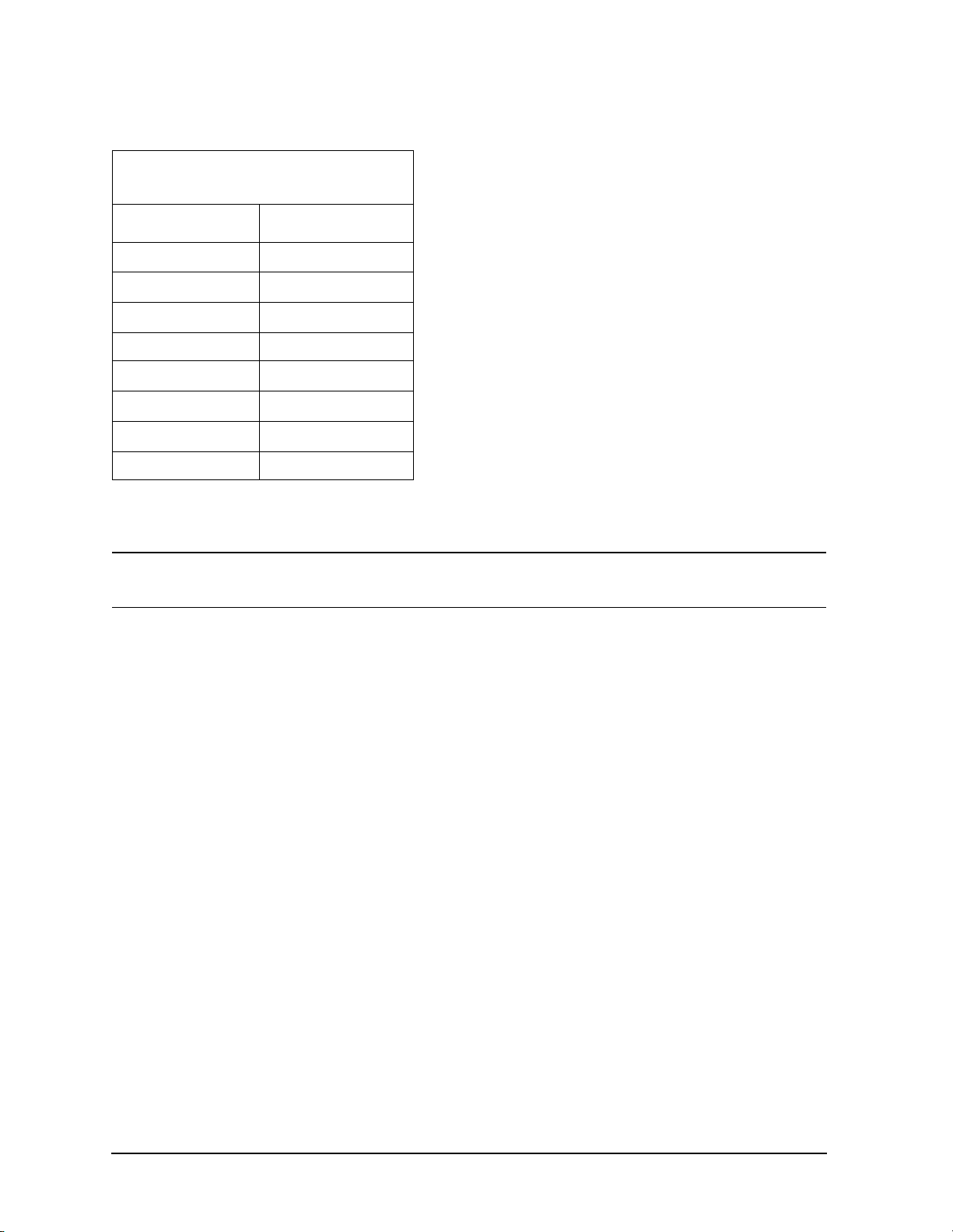
The standard class assignments may be changed to meet your specific requirements. The
following two tables are provided to record the modified standard class assignments.
Table A-4 Blank Form for the 8510 Netw ork Analyzer
Disk File Name: ______________ Calibration Kit Label: ____________
Class A B C D E F G Standard
Class Label
S
A
11
S
B
11
S
C
11
S
A
22
S
B
22
S
C
22
Forward transmission
Reverse transmission
Forward match
Reverse match
Frequency response
R, Q, U, V, and W11644A A-5
Page 60
Standard Definitions
Standard Class Assignments
Table A-5 Blank Form for the PNA Series Network Analyzers
Calibration Kit Label:
________________________________
Class
S11A
S
B
11
S
C
11
Fo rward transmission
S
A
22
B
S
22
S
C
22
Isolation
a. For additional ports, make sure values
match the correct sex of the port.
A
a
IMPORTANT The following calibrations are only supported by certain PNA analyzers. See
your PNA network analyzer embedded help system.
Notes:
1. If you are performing a TRL calibration:
•S
•S
•S
T and S12T must be def ine d as thru standards .
21
A and S22A must be defined as reflection standards.
11
B, S11C, S22B, and S22C must be defined as line standards.
11
2. If you are performing a TRM calibration:
•S
•S
•S
T and S12T must be def ine d as thru standards .
21
A and S22A must be defined as reflection standards.
11
B, S11C, S22B, and S22C must be defined as match standar d s.
11
3. If you are performing an LRM calibration:
•S
•S
•S
4. S
5. S
T and S12T must be def ine d as line standard s.
21
A and S22A must be defined as reflection standards.
11
B, S11C, S22B, and S22C must be defined as match standar d s.
11
B and S11C must be defined as the same standard.
11
B and S22C must be defined as the same standard.
22
A-6 R, Q, U, V, and W11644A
Page 61

Standard Definitions
Nominal Standard Defini ti ons
Nominal Standard Definitions
Standard definitions provide the constants needed to mathematically model the electrical
characteristics (delay, attenuation, and impedance) of each calibration standard. The
nominal values of these constants are theoretically derived from the physical dimensions
and material of each calibr ation standard, o r from actual measured re sponse. T hese values
are used to determine the measurement uncertainties of the network analyzer. The
standard definitions in Tabl es A-6 through A-15 list typical calibration kit parameters
used by the 8510, 872x, and PNA series to specify the mathematical model of each device.
This information must be loaded into the network analyzer to perform valid calibrations.
Refer to your network analyzers user’s guide for instructions on loading calibration
definitions.
NOTE The values in the standard definitions table are valid only over the specified
operating temperature range.
Setting the System Impedance
This kit contains only 50 ohm devices. Ensure the system impedance (Z0) is set t o 5 0 ohms .
Refer to your network analyzer user’s guide for instructions on setting system impedance.
Version Changes
Class assi gn ments and stan dard defini tio n s may change as mo re accurate mo de l and
calibration methods are developed . The disk shipped with the kit for use with the 8510 wil l
contain the most recent version. The default version that comes with the 872x network
analyz e r firmware may be outdated.
R, Q, U, V, and W11644A A-7
Page 62
Standard Definitions
Nominal Standard Defini ti ons
Table A-6 Standar d Definitions for the 8510 with R-band (WR-28)
System Z
a
= 50.0 Ω
0
Calibration Kit Label: WR-28 A.3
Disk File Name: CK_WR-28
2
Standard
Number
1
Type
Short
F
b
−15
10
×
C0
H
−12
10
×
L0
e
F/Hz
−27
10
×
C1
H/Hz
−24
10
×
L1
F/Hz
−36
10
×
C2
2
H/Hz
−33
10
×
L2
2
Short
e
3
4
5
6
7
8
9 Load Fixed 0 50 0 21.071 42.142 WG Fixed
10 Load Sliding 0 50 0 21.071 42.142 WG Sliding
11 Delay/
thru
12
13 Undefined
14 Delay/
thru
15 Delay/
thru
16
17
18
19
20 Load Offset 10.0702 50 0 21.071 42.142 WGλ/4 Offset
21
3
/s
Ω
Loss in G
Frequency
in GHz
Min
Max
d
Coax or Waveguide
Standard Label
F/Hz
−45
10
×
C3
3
c
Offset
H/Hz
−42
10
×
L3
Delay in ps
Fixed, Sliding, or Offset
Ω
0
Z
0 50 0 21.071 42.142 WG Short
10.0702 50 0 21.071 42.142 WGλ/4 Offset
0 50 0 21.071 42.142 WG Thru
0 50 0 21.069 42.138 WG Thru
10.0702 50 0 21.069 42.138 WGλ/4 Delay
a. Ens ur e syst e m Z
of network analyzer is set to this value.
0
b. Open, short, load, delay/thru, or arbitrary impedance.
c. L o ad or ar bi t ra r y impe d ance only.
d. For waveguide, the lower f requency is the same as F
CO.
e. Typical values only. Disk values may be different.
A-8 R, Q, U, V, and W11644A
Page 63
Nominal Standard Defini ti ons
Table A-7 Standard Definitions for the 8510 with Q-band (WR-22)
Standard Definitions
System Z
a
= 50.0 Ω
0
Calibration Kit Label: WR- 22 A.3
Disk File Name: CK_WR-22
2
Standard
Number
1
Type
Short
F
b
−15
10
×
C0
H
−12
10
×
L0
e
−27
−24
F/Hz
10
×
C1
H/Hz
10
×
L1
F/Hz
−36
10
×
C2
2
H/Hz
−33
10
×
L2
2
Short
e
3
4
5
6
7
8
9 Load Fixed 0 50 0 26.338 52.676 WG Fixed
10 Load Sliding 0 50 0 26.338 52.676 WG Sliding
11 Delay/
thru
12
13 Undefined
14 Delay/
thru
15 Delay/
thru
16
17
18
19
20 Load Offset 8.082 50 0 26.338 52.676 WGλ/4 Offset
21
3
/s
Ω
Loss in G
Frequency
in GHz
Min
Max
d
Coax or Waveguide
Standard Label
F/Hz
−45
10
×
C3
3
c
Offset
H/Hz
−42
10
×
L3
Delay in ps
Fixed, Sliding, or Offset
Ω
0
Z
0 50 0 26.338 52.676 WG Short
8.082 50 0 26.338 52.676 WGλ/4 Offset
0 50 0 26.338 52.676 WG Thru
0 50 0 26.338 52.676 WG Thru
8.084 50 0 26.338 52.676 WGλ/4 Delay
a. Ensure system Z
of network analyzer is set to this value.
0
b. Open, short, load, delay/thru, or arbitrary impedance.
c. Load or arbitrary impe dance only.
d. For waveguide, the lower frequency is the same as F
CO.
e. Typical values only. Disk values may be different.
R, Q, U, V, and W11644A A-9
Page 64
Standard Definitions
Nominal Standard Defini ti ons
Table A-8 Standard Definitions for the 8510 with U-band (WR-19)
System Z
a
= 50.0 Ω
0
Calibration Kit Label: WR-19 A.3
Disk File Name: CK_WR-19
2
Standa rd
Number
1
Type
Short
F
b
−15
10
×
C0
H
−12
10
×
L0
e
−27
−24
F/Hz
10
×
C1
H/Hz
10
×
L1
F/Hz
−36
10
×
C2
2
H/Hz
−33
10
×
L2
2
Short
e
3
4
5
6
7
8
9 Load Fixed 0 50 0 31.386 62.772 WG Fixed
10 Load Sliding 0 50 0 31.386 62.772 WG Sliding
11 Delay/
thru
12
13 Undefined
14 Delay/
thru
15 Delay/
thru
16
17
18
19
20 Load Offset 6.643 50 0 31.386 62.772 WGλ/4 Offset
21
3
/s
Ω
Loss in G
Frequency
in GHz
Min
Max
d
Coax or Waveguide
Standard Label
F/Hz
−45
10
×
C3
3
c
Offset
H/Hz
−42
10
×
L3
Delay in ps
Fixed, Sliding, or Offset
Ω
0
Z
0 50 0 31.386 62.772 WG Short
6.643 50 0 31.386 62.772 WGλ/4 Offset
0 50 0 31.386 62.772 WG Thru
0 50 0 31.386 62.772 WG Thru
6.646 50 0 31.386 62.772 WGλ/4 Delay
a. Ens ur e syst e m Z
of network analyzer is set to this value.
0
b. Open, short, load, delay/thru, or arbitrary impedance.
c. L o ad or ar bi t ra r y impe d ance only.
d. For waveguide, the lower f requency is the same as F
CO.
e. Typical values only. Disk values may be different.
A-10 R, Q, U, V, and W11644A
Page 65
Nominal Standard Defini ti ons
Table A-9 Standar d Definitions for the 8510 with V-band (WR-15)
Standard Definitions
System Z
a
= 50.0 Ω
0
Calibration Kit Label: WR- 15 A.3
Disk File Name: CK_WR-15
2
Standard
Number
1
Type
Short
F
b
−15
10
×
C0
H
−12
10
×
L0
e
−27
−24
F/Hz
10
×
C1
H/Hz
10
×
L1
F/Hz
−36
10
×
C2
2
H/Hz
−33
10
×
L2
2
Short
e
3
4
5
6
7
8
9 Load Fixed 0 50 0 39.873 79.745 WG Fixed
10 Load Sliding 0 50 0 39.873 79.745 WG Sliding
11 Delay/
thru
12
13 Undefined
14 Delay/
thru
15 Delay/
thru
16
17
18
19
20 Load Offset 5.376 50 0 39.873 79.745 WGλ/4 Offset
21
3
/s
Ω
Loss in G
Frequency
in GHz
Min
Max
d
Coax or Waveguide
Standard Label
F/Hz
−45
10
×
C3
3
c
Offset
H/Hz
−42
10
×
L3
Delay in ps
Fixed, Sliding, or Offset
Ω
0
Z
0 50 0 39.873 79.745 WG Short
5.376 50 0 39.873 79.745 WGλ/4 Offset
0 50 0 39.873 79.745 WG Thru
0 50 0 39.873 79.745 WG Thru
5.378 50 0 39.873 79.745 WGλ/4 Delay
a. Ensure system Z
of network analyzer is set to this value.
0
b. Open, short, load, delay/thru, or arbitrary impedance.
c. Load or arbitrary impe dance only.
d. For waveguide, the lower frequency is the same as F
CO.
e. Typical values only. Disk values may be different.
R, Q, U, V, and W11644A A-11
Page 66
Standard Definitions
Nominal Standard Defini ti ons
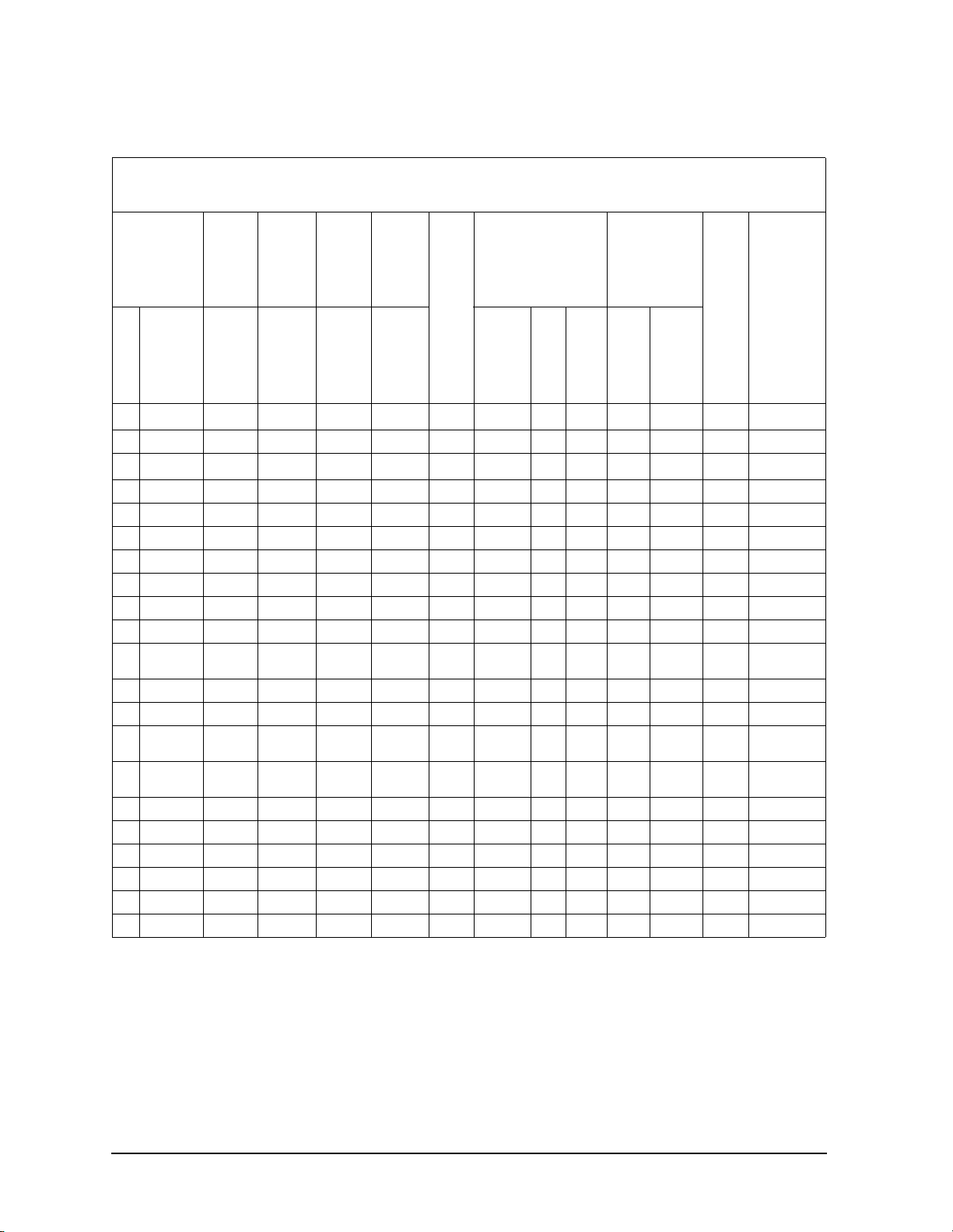
Table A-10 Standard Definitions fo r the 8510 with W-band (WR- 10)
System Z
a
= 50.0 Ω
0
Calibration Kit Label: WR-10 A.3
Disk File Name: CK_WR-10
2
Standa rd
Number
1
Type
Short
F
b
−15
10
×
C0
H
−12
10
×
L0
e
−27
−24
F/Hz
10
×
C1
H/Hz
10
×
L1
F/Hz
−36
10
×
C2
2
H/Hz
−33
10
×
L2
2
Short
e
3
4
5
6
7
8
9 Load Fixed 0 50 0 59.024 118.05 WG Fixed
10 Load Sliding 0 50 0 59.024 118.05 WG Sliding
11 Delay/
thru
12
13 Undefined
14 Delay/
thru
15 Delay/
thru
16
17
18
19
20 Load Offset 3.620 50 0 59.024 118.05 WGλ/4 Offset
21
3
/s
Ω
Loss in G
Frequency
in GHz
Min
Max
d
Coax or Waveguide
Standard Label
F/Hz
−45
10
×
C3
3
c
Offset
H/Hz
−42
10
×
L3
Delay in ps
Fixed, Sliding, or Offset
Ω
0
Z
0 50 0 59.024 118.05 WG Short
3.620 50 0 59.024 118.05 WGλ/4 Offset
0 50 0 59.024 118.05 WG Thru
0 50 0 59.024 118.05 WG Thru
3.620 50 0 59.024 118.05 WGλ/4 Delay
a. Ens ur e syst e m Z
of network analyzer is set to this value.
0
b. Open, short, load, delay/thru, or arbitrary impedance.
c. L o ad or ar bi t ra r y impe d ance only.
d. For waveguide, the lower f requency is the same as F
CO.
e. Typical values only. Disk values may be different.
A-12 R, Q, U, V, and W11644A
Page 67
Standard Definitions
Nominal Standard Defini ti ons
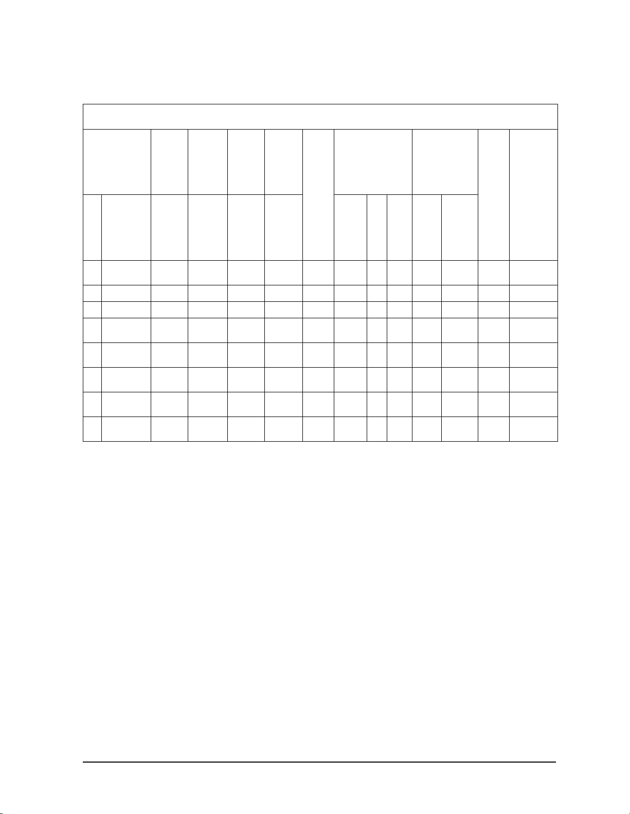
Table A-11 Standard Definitions for the PNA Series with R-band (WR-28)
Standa rd
Number
Type
a
= 50.0 Ω
0
b
System Z
1Short/
offset
2
F
−18
10
×
C0
H
−12
10
×
L0
−30
−24
F/Hz
10
×
C1
H/Hz
10
×
L1
F/Hz
−39
10
×
C2
2
H/Hz
−33
10
×
L2
3
F/Hz
−48
10
×
C3
3
H/Hz
−45
10
×
L3
0 0 0 0 10.07 1 0 21.071 42.142 WGλ/4 Offset/
Calib ra t io n K it La b el : R-band
Offset
/s
Ω
Ω
Fixed or sliding
Delay in ps
0
Z
Loss in G
Frequenc y
in GHz
Min
Max
c
Coax or Waveguide
Standard Label
short
2 Short 0 0 0 0 0 1 0 21.071 42.142 WG Short
3 Load Fixed 0 50 0 21.071 42.142 WG Load
4 Sliding load Sliding 0 50 0 21.071 42.142 WG Sliding/
5 Offset lo ad Fixed 10.07 1 0 21.071 42.142 WGλ/4 Offset
6Delay/
thru
7Delay/
thru
8Delay/
thru
0 1 0 21.071 42.142 WG Thru
0 1 0 21.071 42.142 WG Thru
10.07 50 0 21.071 42.142 WGλ/4 Delay
Load
load
a. Ensure system Z0 of network analyzer is set to this value.
b. Open, short, load, d elay/thru, or arbitrary impedance.
c. For waveguide, the lower frequency is the same as F
CO.
R, Q, U, V, and W11644A A-13
Page 68
Standard Definitions
Nominal Standard Defini ti ons
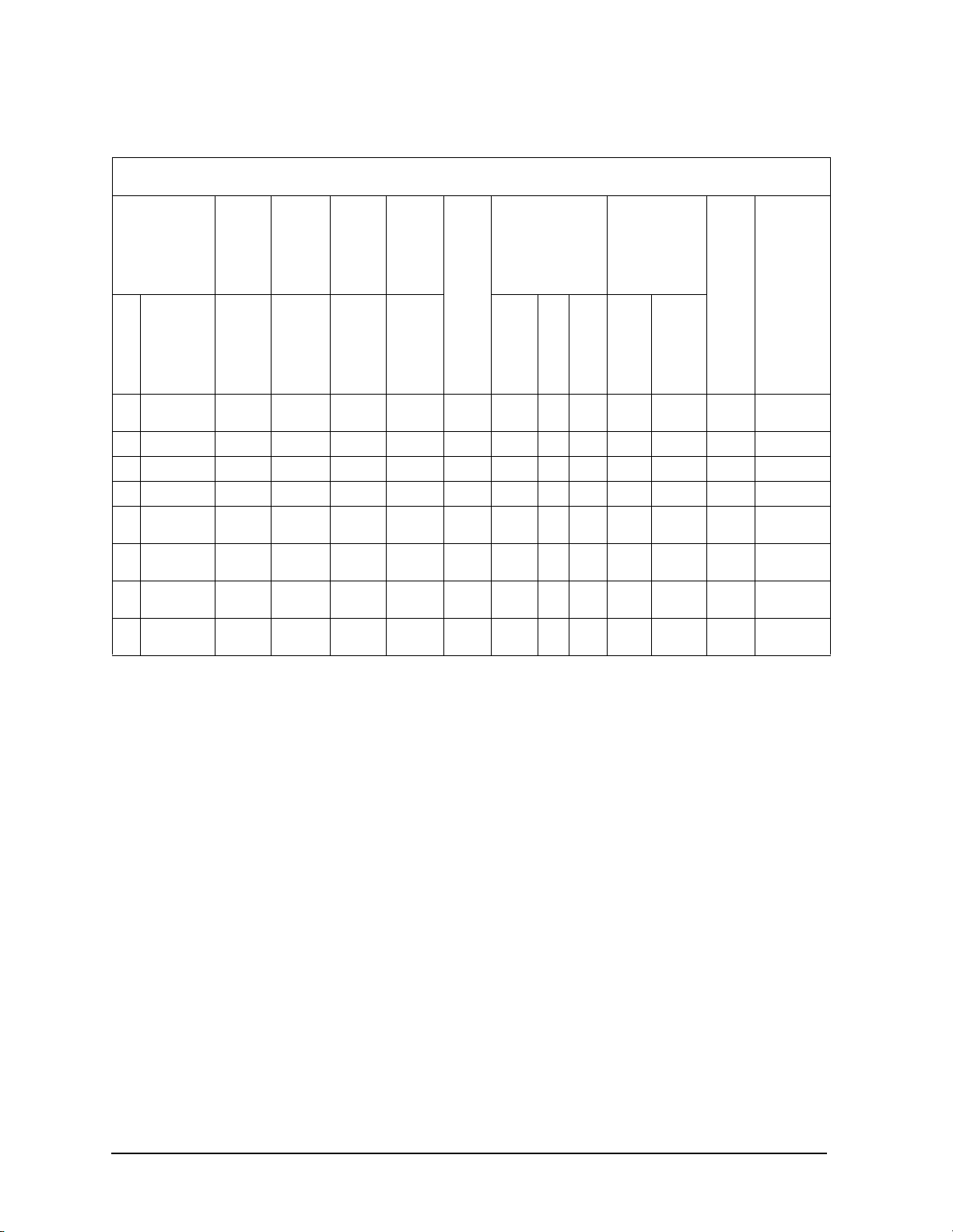
Table A-12 Standard Definitions for the PNA Series with Q-band (WR-22)
System Z
Number
0
Standard
Type
a
= 50.0 Ω
b
1Short/
offset
2
F
−18
10
×
C0
H
−12
10
×
L0
−30
−24
F/Hz
10
×
C1
H/Hz
10
×
L1
F/Hz
−39
10
×
C2
2
H/Hz
−33
10
×
L2
3
F/Hz
−48
10
×
C3
3
H/Hz
−45
10
×
L3
0 0 0 0 8.082 1 0 26.338 52.676 WGλ/4 Offset/
Calibration Kit Label: Q-band
Offset
/s
Ω
Ω
Fixed or sliding
Delay in ps
0
Z
Loss in G
Frequency
in GHz
Min
Max
c
Coax or Waveguide
Standard Label
short
2 Short 0 0 0 0 0 1 0 26.338 52.676 WG Short
3 Load Fixed 0 50 0 26.338 52.676 WG Load
4 Sliding load Sliding 0 50 0 26.338 52.676 WG Sliding load
5 Of fset load Fixed 8.0 82 1 0 26.338 52.676 WGλ/4 Offset/
load
6Delay/
0 1 0 26.338 52.676 WG Thru
thru
7Delay/
0 1 0 26.338 52.676 WG Thru
thru
8Delay/
8.082 50 0 26.338 52.676 WGλ/4 Delay
thru
a. Ensu r e syst e m Z0 of network analyzer is set to this value .
b. Open, short, load, delay/thru, or arbitrary imped ance.
c. For waveguide, the lower frequency i s the same as F
CO.
A-14 R, Q, U, V, and W11644A
Page 69
Standard Definitions
Nominal Standard Defini ti ons
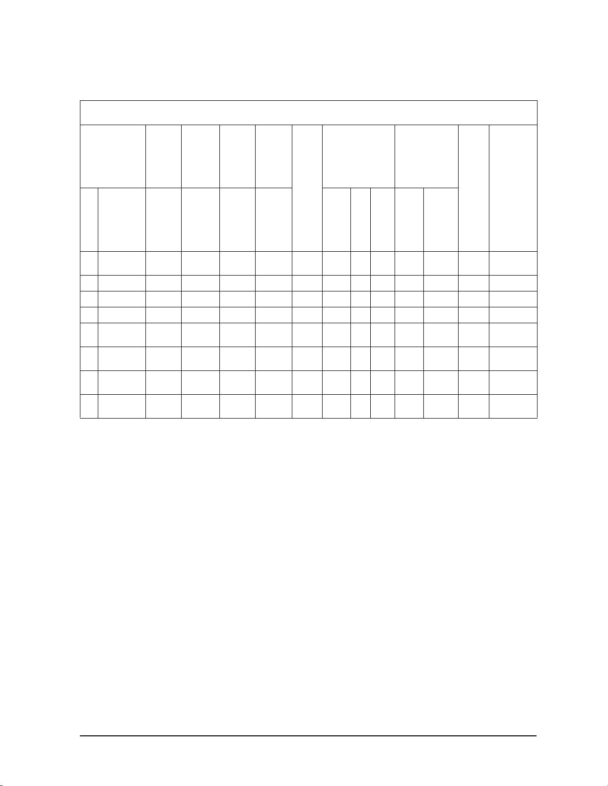
Table A-13 Standard Definitions for the PNA Series with U-band (WR-19)
Standa rd
Number
Type
a
= 50.0 Ω
0
b
System Z
1Short/
offset
2
F
−18
10
×
C0
H
−12
10
×
L0
−30
−24
F/Hz
10
×
C1
H/Hz
10
×
L1
F/Hz
−39
10
×
C2
2
H/Hz
−33
10
×
L2
3
F/Hz
−48
10
×
C3
3
H/Hz
−45
10
×
L3
0 0 0 0 6.643 1 0 31.386 62.772 WGλ/4 Offset/
Calib ra t io n K it La b el : U-band
Offset
/s
Ω
Ω
Fixed or sliding
Delay in ps
0
Z
Loss in G
Frequency
in GHz
Min
Max
c
Coax or Waveguide
Standard Label
short
2 Short 0 0 0 0 0 1 0 31.386 62.772 WG Short
3 Load Fixed 0 50 0 31.386 62.772 WG Load
4 Sliding load Sliding 0 50 0 31.386 62.772 WG Sliding load
5 Offset load Fixed 6.643 1 0 31.386 62.772 WGλ/4 Offset/
load
6Delay/
0 1 0 31.386 62.772 WG Thru
thru
7Delay/
0 1 0 31.386 62.772 WG Thru
thru
8Delay/
6.643 50 0 31.386 62.772 WGλ/4 Delay
thru
a. Ensure system Z0 of network analyzer is set to this value.
b. Open, short, load, d elay/thru, or arbitrary impedance.
c. For waveguide, the lower frequency is the same as F
CO.
R, Q, U, V, and W11644A A-15
Page 70
Standard Definitions
Nominal Standard Defini ti ons
Table A-14 Standard Definitions for the PNA Series with V-band (WR-15)
System Z
Number
0
Standard
Type
a
= 50.0 Ω
b
1Short/
offset
2
F
−18
10
×
C0
H
−12
10
×
L0
−30
−24
F/Hz
10
×
C1
H/Hz
10
×
L1
F/Hz
−39
10
×
C2
2
H/Hz
−33
10
×
L2
3
F/Hz
−48
10
×
C3
3
H/Hz
−45
10
×
L3
0 0 0 0 5.376 1 0 39.873 79.745 WGλ/4 Offset/
Calibration Kit Label: V-band
Offset
/s
Ω
Ω
Fixed or sliding
Delay in ps
0
Z
Loss in G
Frequency
in GHz
Min
Max
c
Coax or Waveguide
Standard Label
short
2 Short 0 0 0 0 0 1 0 39.873 79.745 WG Short
3 Load Fixed 0 50 0 39.873 79.745 WG Load
4 Sliding load Sliding 0 50 0 39.873 79.745 WG Sliding load
5 Offset load Fixed 5.376 1 0 39.873 79.745 WGλ/4 Offset/
load
6Delay/
0 1 0 39.873 79.745 WG Thru
thru
7Delay/
0 1 0 39.873 79.745 WG Thru
thru
8Delay/
5.376 50 0 39.873 79.745 WGλ/4 Delay
thru
a. Ensu r e syst e m Z0 of network analyzer is set to this value .
b. Open, short, load, delay/thru, or arbitrary imped ance.
c. For waveguide, the lower frequency i s the same as F
CO.
A-16 R, Q, U, V, and W11644A
Page 71
Standard Definitions
Nominal Standard Defini ti ons
Table A-15 Standard Definitions for the PNA Series with W-band (WR-10)
Standard
Number
Type
a
= 50.0 Ω
0
b
System Z
1Short/
offset
2
F
−18
10
×
C0
H
−12
10
×
L0
−30
−24
F/Hz
10
×
C1
H/Hz
10
×
L1
F/Hz
−39
10
×
C2
2
H/Hz
−33
10
×
L2
3
F/Hz
−48
10
×
C3
3
H/Hz
−45
10
×
L3
0 0 0 0 3.62 1 0 59.024 118.05 WGλ/4 Offset/
Calibration Kit Label: W-band
Offset
/s
Ω
Ω
Fixed or sliding
Delay in ps
0
Z
Loss in G
Frequency
in GHz
Min
c
Max
Coax or Waveguide
Standard Label
short
2 Short 0 0 0 0 0 1 0 59.024 118.05 WG Short
3 Load Fixed 0 50 0 59.024 118.05 WG Load
4 Sliding load Sliding 0 50 0 59.024 118.05 WG Sliding load
5 Offset lo ad Fixed 3.62 1 0 59.024 118.05 WGλ/4 Offset/
load
6Delay/
0 1 0 59.024 118.05 WG Thru
thru
7Delay/
0 1 0 59.024 118.05 WG Thru
thru
8Delay/
3.62 50 0 59.024 118.05 WGλ/4 Delay
thru
a. Ensure system Z0 of network analyzer is set to this value.
b. Open, short, load, d elay/thru, or arbitrary impedance.
c. For waveguide, the lower frequency is the same as F
CO.
R, Q, U, V, and W11644A A-17
Page 72
Standard Definitions
Nominal Standard Defini ti ons
Blank Forms
The standard definitions may be changed to meet your specific requirements. The
following two tables are provided to record the modified standard definitions.
Table A-16 Blank Form for the 8510 Network Analyzer
System Z
a
= ____________
0
Disk File Name: ______________________ _____
Standard
Number
1
2
3
4
5
6
7
8
9
10
11
12
13
14
15
16
17
18
19
20
21
2
F
b
−15
10
×
C0
H
−12
10
×
Type
L0
−27
−24
F/Hz
10
×
C1
H/Hz
10
×
L1
F/Hz
−36
10
×
C2
2
H/Hz
−33
10
×
L2
3
F/Hz
−45
10
×
C3
3
H/Hz
−42
10
×
L3
Calibration Kit Label: ______________________________
c
Fixed, Sliding, or Offset
Offset
/s
Ω
Ω
Delay in ps
0
Z
Loss in G
Frequency
in GHz
Min
d
Max
Coax or Waveguide
Standard Label
a. Ens ur e syst e m Z0 of network analyzer is set to this value.
b. Open, short, load, delay/thru, or arbitrary impedance.
c. L o ad or ar bi t ra r y impe d ance only.
d. For waveguide, the lower f requency is the same as F
CO.
A-18 R, Q, U, V, and W11644A
Page 73
Table A-17 Blank Form for the PNA Series Network Analyzer
Standard Definitions
Nominal Standard Defini ti ons
Standard
Number
Type
a
= _______________ Calibration Kit Label: ___________________________
0
2
b
F
−18
10
×
C0
H
−12
10
×
L0
−30
−24
F/Hz
10
×
C1
H/Hz
10
×
L1
F/Hz
−39
10
×
C2
2
H/Hz
−33
10
×
L2
3
F/Hz
−48
10
×
C3
3
H/Hz
−45
10
×
L3
Fixed or sliding
System Z
1
2
3
4
5
6
7
8
a. Ensure system Z0 of network analyzer is set to this value.
b. Open, short, load, d elay/thru, or arbitrary impedance.
c. For waveguide, the lower frequency is the same as F
Delay in ps
CO.
Offset
Frequency
c
in GHz
/s
Ω
Ω
0
Z
Loss in G
Min
Max
Coax or Waveguide
Standard Label
R, Q, U, V, and W11644A A-19
Page 74

Standard Definitions
Nominal Standard Defini ti ons
A-20 R, Q, U, V, and W11644A
Page 75

Index
A
Agilent Technologies
flanges
, 6-2
7-10
, 3-2
, 5-3
, 5-3
, 3-4
, 3-3
, 3-4
, 3-5
, 3-5
, 3-6
, 6-4
, ii
, 7-14
, 4-6
, 4-5
, 2-2
, 1-2
, 6-4
, A-18
, 7-4, 7-6, 7-8,
, 1-2
, ii
, 1-2
, 5-2
, 5-3
, A-7
, 7-6, 7-8,
, 7-12
, 1-3
, 2-3
, 5-2
, 2-2
, 3-3
, 3-5
, 3-3
, 3-4
, 3-5
contacting
warranty
alcohol
isopropyl
part num ber
precautions for use of
aligning
non-precision and precision
precision flanges
altitude, s pecifications
analyzers , compatible
assistance
contacting agilent
B
blank forms
standard cla ss assi gnme nts
standard definitions
box, part number
7-10, 7-12
C
cal kit
contents
misuse of
overview
verifying
calibration
bad
certificate of
constants
definitions
disk, part number
part num ber
devices
kits, intended use
report
residual err ors
standards
sticker
temperature
calibration applications
1/4 load
1/4 short
isolation
line
load
offset load
offset short
reflect
short
thru
, 4-3
, A-5
calibration defin ition, wavelengt h
shim
, 3-7
calibration kit
contents
misuse of
overview
parts not incl uded
performance
warranty
case , stora ge
certificate of calibration
certification, device specifications
characte ristics
mechanical
class assignm e nts
blank forms
class assignments, standard
cleaning
connectors
mating plane surfaces
supplies
compatible analyzers
component identifica tion sheets
Q and U-band
R-band
V and W-band
comp r essed ai r
for cleaning
cond uc tive tab l e m at, part
connectin g
flange s
for ESD protec tion
waveguides
connections
connector
cleaning
mating plane surfaces
constants
part numbers
contacting Agilent Technologies
contents
calibration kit
drawing o f
incomplete
D
damage
, 1-2
drawin g of
, 7-5, 7-7, 7-9, 7-11,
7-13
, ii
, 1-2
, 7-14
how Agilent verifies
, ii
, 7-4, 7-6, 7-8, 7-10,
7-12
2-3
, 2-3
, A-5
A-3, A-5
, 4-3
, 1-3
part number
, 7-14
, 1-2
, 7-7, 7-9
, 7-5
, 7-11, 7-13
, 4-3
number
, 7-14
, 4-4, 4-7
, 4-2, 7-14
, 4-4
, 4-4
, 4-3
, A-7
, 7-4, 7-8, 7-12
6-4
, 1-2
, 7-5, 7-7, 7-9, 7-11,
7-13
, 1-3
, 5-2
, 5-3
, A-2,
, 4-3
, 4-3
,
caused by electrostatic
discharge
data, recertification
definitions
calibration
standard
A-11, A-12, A-13, A-14,
A-15, A-16, A-17
deviation from nominal phase
device
calibration
cleaning
com patib le anal y zers
connecting
handling
maintenance
,
performance, verifying
specifications
certificat ion of
electrical
traceability
storage
temperature
visual inspection
disk
calibration definition s
part num ber
7-10, 7-12
specifications and performance
part num ber
7-10, 7-12
document ed kits
E
electrical
characteristics
effec ts of temp er ature
specifications
electrostatic discharge, See ESD
environmental
regulations
requirements
specifications
equipment requir ed
ESD
, 4-2
protection
supplies, par t num ber
F
flange, connect
flowchart , troubl e s h o oting
frequency specification
G
general information
, 4-2
, 3-7
, A-7, A-8, A-9, A-10,
, 3-2
, 4-3
, 4-4
, 4-8
, 1-5
, 2-3
, 2-3
, 5-2, 5-3
, 4-8
, 2-2
, 4-2
, 7-4, 7-6, 7-8,
, 7-4, 7-6, 7-8,
, 1-3
, 2-3
, 4-3
, 2-2
, 2-2
, 4-2
, 4-7
, 5-3
, 2-3
, 1-2
, 5-2
, 2-2
, 1-3
, 7-14
, 6-2
, 2-3
, 1-1
R, Q, U, V, and W11644A Index-1
Page 76

Index
grounding cord, part number,
7-14
H
handling
heel strap , par t num ber
history, serial numbers
humidity specifications
I
impedance, system
incoming inspection
information, tr oubleshooting
inspection
flange connection
incoming
visual
isolation
isopropyl alcohol
part number
precauti ons for use of
K
kit
contents
overview
performance
warranty
L
line
load
load, part numbers
M
maintenance
of devices
preventive
manual
part number
mat
conductive
for ESD protection
mating plane surfaces
cleaning
connector
mechanical characteristics
MIL-STD 45662
calibration
, 4-8
, 1-3
, 4-2
, 3-3
, 1-2, 7-4, 7-8, 7-12
drawin g of
, 7-5, 7-7, 7-9, 7-11,
7-13
, 1-2
failure
, 6-2
verification
, ii
, 3-3
, 3-4
, 1-5
, 1-5
part number
, 4-3
, 4-3
, 5-3
, 7-14
, 1-3
, 2-2
, A-7
, 1-3
, 4-7
, 7-14
, 4-3
, 5-2
, 7-4
, 7-4, 7-8, 7-12
, 7-14
, 4-2
, 2-3
, 6-4
N
National Institute of Standards
and Technology (NIST)
5-2
network analyzers, compatible
1-2
nitrogen, for cleaning
nominal standard d efinitions
non-precision flanges, aligning
4-6
numbers
replaceable parts
7-12, 7-14
serial
, 1-4
O
offset load
offset short
ordering, parts
oxygen
P
part numbers
included in kit
not included in kit
of items not in kit
performance
and specificat ions dis k
verifica tion
perf orman c e te s t
port 1 and 2
precision flanges
preventive maintenance
procedures
aligning flanges
cleaning
tightening flanges
R
recertification
how often
services included
record serial number
reflect
regulations
environmental
replaceable parts
drawin g of
Q11644A WR-22
R11644A WR-28
U11644A WR-19
V11644A WR-15
report, calibration
required equipment
, 3-4
, 3-5
, 4-3
7-10, 7-12
, 4-3
, 5-3
, 3-5
7-13
, 7-3, 7-4, 7-8,
, 7-3, 7-14
, 7-3
, 7-4, 7-12
, 7-14
, 5-2, 6-2
, 5-4, 5-5
, 3-2
, 4-4, 4-5, 4-6
, 4-5
, 4-7
, 5-3
, 2-2, 4-3
, 7-3, 7-14
, 7-5, 7-7, 7-9, 7-11,
, 7-8
, 7-4
, 7-8
, 7-12
, 5-3
, 1-3
, 2-3,
, 4-3
, A-7
, 7-8
, 7-6, 7-8,
, 1-5
, 1-4
requirements, environmental
residual errors
return kit or device to A gilent
1-3, 6-4
,
,
return loss sp e ci f ic ation
S
serial numbers
devices
history
recording
service
, 6-4
service tag
shim
, 3-2
short
, 3-5
part numbers
7-10, 7-12
specifications
altitude
operating
storage
and perfo rmance dis k
part number
7-12
certification of
characte ristics
deviation from nominal phase
2-3
device
electrical
environmental
frequency
operating
return loss
storage
temperature
traceability
standard cl ass ass ig nm ents
8510
, A-2, A-3, A-5
blank forms
standard definitions
blank forms
nominal
PNA series
A-16, A-17
Q-band (WR-22)
R-band (WR-28)
A-14
U-band (WR-19)
A-16, A-17
V-band (WR-15)
A-17
W-band (WR-10)
standard section
standards
international
, 2-3
, 1-4
, 1-4
, 1-3
, 1-4
, 5-3, 6-4
, 7-4, 7-6, 7-8,
, 2-2
, 2-2
, 2-2
, 7-6, 7-8, 7-10,
, 2-3
, 2-3
, 2-3
, 2-3
, 2-2
, 2-3
, 2-2
, 2-3
, 2-2
, 2-2
, 5-2, 5-3
, A-5
, A-7, A-18
, A-18
, A-7
, A-13, A-14, A-15,
, A-9, A-14
, A-8, A-13,
, A-10, A-15,
, A-11, A-16,
, A-12, A-17
, 3-2
, 2-3
, 2-2
,
, 2-3
,
, A-2
Index-2 R, Q, U, V, and W11644A
Page 77

Index
Nati o nal Institut e of Standards
and Tec hnology (NIST)
5-2
static electricity
storage
storage case, part number
strap
supplies
system impedan ce
T
table mat
tag, service
temperature
termination
test data
test, performance
thru
traceability
troubleshooting, flow chart
, 4-8
7-6, 7-8, 7-10, 7-12
heel an d wri st , pa r t n u mb er
7-14
cleaning
part num ber
for ESD protection
part number
affect on el ectrical p erforman ce
2-2
cautions about
environmental requirements
2-2
error-corrected
measurement
specifications
verification and measurement
2-2
, 3-6
of device specifications
, 4-2
, 1-3
, 7-14
, A-7
, 4-2
, 7-14
, 5-3, 6-4
, 2-2
, 2-2
, 2-2
, 2-2
, 3-2
, 5-3
, 5-4, 5-5
, 2-3,
, 7-4,
, 5-2, 5-3
, 6-2
port 1 and 2
verification device
waveguide, connecting
wave length shim
wavelength shim, calibration
definition
wrist strap
for ESD protec tion
,
part number
, 3-2
, 3-2
, 4-4
, 3-2
, 3-7
, 4-2
, 7-14
,
,
,
U
user’s and service guide
part number
7-12
V
verification
device
performance
temperature
version changes, system
impedance
visual inspection
W
warranty
waveguide straight
R, Q, U, V, and W11644A Index-3
, 7-6, 7-8, 7-10,
, 5-2
, 5-3
, 2-2
, A-7
, 4-2
, ii
 Loading...