

Page 1

User’s Guide
Publication number 54753-97015
Third edition, May 2000
For Safety information, Warranties, and Regulatory information, see pages
behind the index
© Copyright Agilent Technologies 2000
All Rights Reserved
Agilent 54753A and 54754A
TDR Plug-in Modules
Page 2

Agilent 54753A and 54754A Plug-in Modules
The Agilent 54753A and 54754A TDR plug-in modules provide you with
TDR and TDT measurement features. In addition to the TDR and TDT
measurement features, the TDR plug-ins provide two accurate
oscilloscope measurement channels with user selectable bandwidths of
12.4 or 18 GHz. The lower bandwidth mode provides excellent
oscilloscope noise performance for accurate measurement of small
signals. The high bandwidth mode provides high-fidelity display and
measurement of very high-speed waveforms.
The Agilent 54753A TDR plug-in module provides:
• Automatic and manual single-ended TDR and TDT measurement
capability
• Automatic and manual waveform, histogram, FFT, waveform math,
eye pattern measurements, statistical measurements, and limit
testing capabilities.
• User selectable 12.4 or 18 GHz bandwidth (Channel 1).
• User selectable 12.4 or 20 GHz bandwidth (Channel 2).
• 2.5 GHz bandwidth trigger channel.
• 3.5 mm (m) connectors.
The Agilent 54754A TDR plug-in module provides:
• Automatic and manual single-ended and differential TDR and TDT
measurement capability.
• Automatic and manual waveform, histogram, FFT, waveform math,
eye pattern measurements, statistical measurements, and limit
testing capabilities.
• User selectable 12.4 or 18 GHz bandwidth.
• 2.5 GHz bandwidth trigger channel.
• 3.5 mm (m) connectors.
ii
Page 3

Accessories Supplied
The following accessories are supplied with the TDR plug-in modules:
One 50 ohm SMA (m) terminator, Agilent part number 1250-2153
Two SMA shorts (m), Agilent part number 0960-0055
TDR Demo Board, Agilent part number 54754-66503
One User’s Guide
One Programmer’s Guide
One Service Guide
Accessories Available
The following accessories are available for use with the TDR plug-in
modules.
Options
Option 0B1 Additional set of user documentation
Option 001 Agilent 83480A mainframe operating system upgrade
Option 002 Agilent 54750A mainframe operating system upgrade
Option 003 Delete demo board
Agilent 54755A TDR option for Agilent 83480A mainframe operating system
upgrade
Optional Accessories
Agilent 10086A ECL terminator
Agilent 54006A 6 GHz divider probe
Agilent 54007A accessory kit
Agilent 54008A 22 ns delay line
Agilent 54118A 500 MHz to 18 GHz trigger
Agilent 54701A 2.5 GHz Active Probe with Option 001
Connection Devices
SMA (f-f) adapter, Agilent part number 1250-1158
APC 3.5 (f-f) adapter, Agilent part number 1250-1749
iii
Page 4

In This Book
This book is the operating manual for the Agilent 54753A and 54754A TDR plugin modules, and contains 13 chapters.
General Information Chapter 1 contains overview information, menu
and front panel key information, and trigger information. Chapter 2
contains important information on the care of the TDR plug-in connectors.
TDR Front Panel and Menu Keys Chapter 3, 4, 5 and 6 describe the
front panel keys and all the menu keys.
Task Oriented Examples Chapter 7 contains example single-ended
TDR measurements using a demo board included with each TDR plug-in
module. Chapter 8 contains example differential TDR measurements.
TDR Theory Chapters 9, 10, and 11 contain in-depth theory of TDR
transmission lines and how to use TDR in designing systems.
Specifications and Characteristics Chapter 12 contains the
specifications and characteristic for the TDR plug-in modules.
Problems and Error Messages Chapter 13 contains troubleshooting
information and error messages.
iv
Page 5

Contents
The Instrument at a Glance 1-1
Menu and Key Conventions 1-3
The Agilent 54753A, 54754A TDR Plug-In Modules 1-4
Plug-in Module Purpose 1-4
Front Panel of the Plug-in Module 1-4
Getting the Best Performance 1-5
Installing a Plug-in Module 1-6
Trigger 1-6
Care and Handling of Precision Connectors 2-1
3.5 mm Connector Care 2-3
Connector Wear 2-3
Operator Skill 2-3
Device Specifications 2-3
Accuracy Considerations 2-6
Visual Inspection 2-8
Mechanical Inspection 2-8
Connecting the Devices 2-16
Setup Channel Menu 3-1
Displaying the Setup Channel menu 3-4
Display 3-4
Scale 3-4
Offset 3-5
Bandwidth. . . 3-6
Alternate scale. . . 3-6
Calibrate . . . 3-8
Contents-1
Page 6

Contents
Calibration Procedures 3-11
Performing a Plug-in Module Vertical Calibration 3-12
Calibrating Voltage Probes 3-12
Agilent 54753A TDR/TDT Setup Menu 4-1
Displaying the TDR/TDT Setup Menu 4-4
Stimulus 4-4
TDT 1 dest 4-4
TDR 1 dest 4-5
Normalize response . . . 4-5
TDR rate automatic . . . (250 kHz) 4-8
Preset TDR/TDT 4-8
Agilent 54754A TDR/TDT Setup Menu 5-1
Displaying the TDR/TDT Setup Menu 5-7
Stimulus 5-7
TDT 1 dest 5-8
Normalize response . . . 5-8
TDR rate automatic . . . (250 kHz) 5-11
Preset TDR/TDT 5-12
TDT 2 dest 5-13
Normalize response . . . 5-13
TDR rate automatic . . . (250 kHz) 5-16
Preset TDR/TDT 5-17
TDT 1 dest 5-18
TDT 2 dest 5-18
Normalize 1 response . . .
Normalize 2 response . . . 5-19
Contents-2
Page 7

TDR rate automatic . . . (250 kHz) 5-21
Preset TDR/TDT 5-22
TDR/TDT 5-23
TDR response 1 5-23
TDR response 2 5-24
TDT response 1 5-25
TDT response 2 5-25
Establish ref plane 5-26
TDR rate automatic . . . (250 kHz) 5-27
Preset TDR/TDT 5-28
TDT 1 dest 5-30
TDR 1 dest 5-30
Normalize response . . . 5-31
TDR rate automatic . . . (250 kHz) 5-34
Preset TDR/TDT 5-34
Contents
Measure and Other TDR Specific Menus 6-1
TDR/TDT Measure Menu 6-4
Marker Menu 6-9
Reference 6-9
Marker units . . . 6-9
Response Menu Items 6-10
Single-ended TDR Measurements 7-1
Single-ended TDR Features 7-3
Establishing the Reference Plane and Normalizing 7-8
Measuring Transmission Line Impedance 7-19
Measuring Transmission Line Percent Reflection 7-25
Contents-3
Page 8

Contents
Measuring Excess L/C 7-32
Measuring the Distance to a Discontinuity 7-37
Differential TDR Measurements 8-1
Differential TDR Features 8-3
Measuring Differential and Common Mode Impedance 8-5
Making Differential TDT Measurements 8-15
TDR Fundamentals 9-1
Propagation on a Transmission Line 9-4
Step Reflection Testing 9-6
Instrument Configuration 9-23
Improving Time Domain Network Measurements 10-1
Sources of Measurement Error 10-3
Removing Measurement Errors 10-6
Transmission Line Theory Applied to Digital Systems 11-1
Transmission Line Design 11-2
Signal Propagation Delay for Microstrip and Strip Lines with Distributed or Lumped
Loads 11-15
Microstrip Transmission Line Techniques Evaluated Using TDR Measurements 11-21
References 11-38
Contents-4
Page 9

Specifications and Characteristics 12-1
Specifications 12-3
Vertical Specifications 12-4
Environmental Specifications 12-5
Power Requirements 12-7
Weight 12-7
Characteristics 12-7
Trigger Input Characteristics 12-7
Product Regulations 12-8
In Case of Difficulty 13-1
Contents
If You Have Problems 13-3
If the Mainframe Does Not Operate 13-3
If the Plug-in Does Not Operate 13-4
Error Messages 13-5
Contents-5
Page 10

Contents
Contents-6
Page 11

1
The Instrument at a Glance
Page 12

Operating the Instrument
What you’ll find in this chapter
This chapter describes:
• the key conventions used in this manual
• the front panel, rear panel and keys that do not display menus on the screen
Understanding the information in this chapter will help you successfully operate
the instrument.
CAUTION
The input circuits can be damaged by electrostatic discharge (ESD). Therefore,
avoid applying static discharges to the front-panel input connectors. Before
connecting any coaxial cable to the connectors, momentarily short the center
and outer conductors of the cable together. Avoid touching the front-panel
input connectors without first touching the frame of the instrument. Be sure
the instrument is properly earth-grounded to prevent buildup of static charge.
1-2
Page 13

The Instrument at a Glance
Menu and Key Conventions
Menu and Key Conventions
The keys labeled Trigger, Disk, and Run are all examples of front-panel keys.
Pressing some front-panel keys accesses menus of functions that are displayed
along the right side of the display screen. These menus are called softkey
menus.
Softkey menus list functions other than those accessed directly by the frontpanel keys. To activate a function on the softkey menu, press the unlabeled key
immediately next to the annotation on the screen. The unlabeled keys next to
the annotation on the display are called softkeys.
Additional functions are listed in blue type above and below some of the frontpanel keys. These functions are called shifted functions. To activate a shifted
function, press the blue front-panel Shift key and the front-panel key next to
the desired function.
Throughout this manual front-panel keys are indicated by bold lettering of the
key label, for example, Time base. Softkeys are indicated by italic lettering of
the key label, for example, Scale. The softkeys displayed depend on the front-
panel key pressed and which menu is selected. Shifted functions are indicated
by the front-panel Shift key followed by the shaded shifted function, for example
the Local function (above the Stop/Single front-panel key) will be shown as Shift,
Local.
A softkey with On and Off in its label can be used to turn the softkey’s function
on or off. To turn the function on, press the softkey so On is highlighted. To
turn the function off, press the softkey so Off is highlighted. An On or Off softkey
function will be indicated throughout this manual as: Te st On
A softkey such as Sweep Triggered Freerun offers you a choice of functions. In
this case you could choose Triggered by pressing the softkey until Triggered is
highlighted, or choose Freerun by pressing the softkey until Freerun is
highlighted. Softkey choices will be indicated throughout this manual as: Sweep
Triggered Freerun Triggered
When some softkeys, such as Calibrate Probe, are pressed the first time, a
calibration will be made. Some softkeys, such as Offset require the entry of a
numeric value. To enter or change the value, use the general purpose knob
located below the front-panel Measure section.
.
.
1-3
Page 14

The Instrument at a Glance
The Agilent 54753A, 54754A TDR Plug-In Modules
The Agilent 54753A, 54754A TDR Plug-In Modules
The TDR plug-in modules are two of several plug-in modules available for the
Agilent 83480A and Agilent 54750A mainframes.
Plug-in Module Purpose
The purpose of the plug-in module is to provide measurement channels,
including sampling, for the mainframe. The plug-in module scales the input
signal, sets the bandwidth of the system, and allows the offset to be adjusted so
the signal can be viewed. The output of the plug-in module is an analog signal
that is applied to the ADCs on the acquisition boards inside the mainframe. The
plug-in module also provides a trigger signal input to the time base/trigger board
inside the mainframe.
Front Panel of the Plug-in Module
The plug-in module takes up two, of the four, mainframe slots. The front panel
of the plug-in module has two channel inputs and an external trigger input. The
front panel also has two probe power connectors for Agilent 54700-series
probes, an auxiliary power connector for general purpose use, and a key for
each channel that displays the softkey menu. The softkey menu allows you to
access the channel setup features of the plug-in module for the selected input.
1-4
Page 15
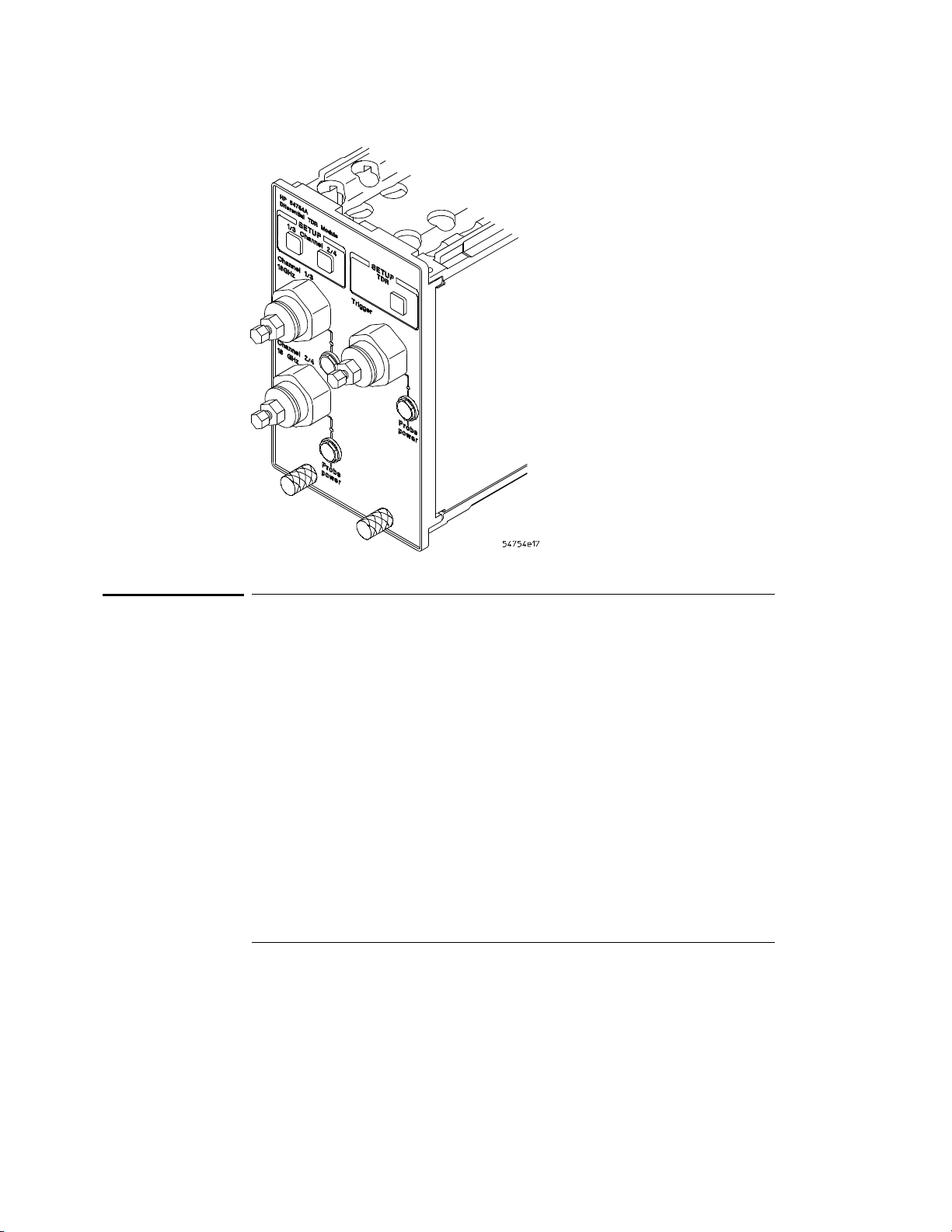
Figure 1-1
The Instrument at a Glance
Getting the Best Performance
Front panel of the plug-in module.
Getting the Best Performance
To ensure you obtain the specified accuracy, you must perform a plug-in module
vertical calibration. The calibration must also be performed when you move a
plug-in module from one slot to another or to a different mainframe. Refer to
“Performing a Plug-in Module Vertical Calibration” on page 3-12 for information
on performing a plug-in module vertical calibration.
1-5
Page 16

The Instrument at a Glance
Installing a Plug-in Module
Installing a Plug-in Module
You do not need to turn off the mainframe to install or remove a plug-in module.
The plug-in module can be installed in slots 1 and 2 or 3 and 4 on the
Agilent 83480A, 54750A mainframe. The plug-in module will not function if it
is installed in slots 2 and 3.
To make sure the instrument meets all of the published specifications, there
must be a good ground connection from the plug-in module to the mainframe.
The RF connectors on the rear of the plug-in module are spring loaded, so fingertighten the knurled screw on the front panel of the plug-in module to make sure
the plug-in is securely seated in the mainframe.
CAUTION
CAUTION
CAUTION
Do not use extender cables to operate the plug-in module outside of the
mainframe. The plug-in module and/or mainframe can be damaged by
improper grounding when using extender cables.
Trigger
The external trigger level range for this plug-in module is ±1 V. The trigger
source selection follows the slots the plug-in module is installed in. For example,
if the plug-in module is installed in slots 1 and 2, then the trigger source is listed
as trigger 2. If it is installed in slots 3 and 4, then the trigger source is listed as
trigger 4.
The maximum safe input voltage is ±2 V + peak ac (+16 dBm). Therefore, to
!
avoid damaging the trigger input circuitry, do not apply any voltage outside
this range.
The input circuits can be damaged by electrostatic discharge (ESD).
Therefore, avoid app lying static discharges to the front-panel i nput connectors.
Before connecting any coaxial cable to the connectors, momentarily short the
center and outer conductors of the cable together. Avoid touching the frontpanel input connectors without first touching the frame of the instrument. Be
sure the instrument is properly earth-grounded to prevent buildup of static
charge.
1-6
Page 17

2
Care and Handling of Precision Connectors
Page 18

The Care and Handling of Precision
Connectors
What you’ll find in this chapter
This chapter describes:
• 3.5 mm connector care
• connector wear
• device specifications
• accuracy considerations
• visual inspection
• mechanical inspection
• connecting devices
Understanding the information in this chapter will help you successfully operate
the instrument.
CAUTION
The input circuits can be damaged by electrostatic discharge (ESD). Therefore,
avoid applying static discharges to the front-panel input connectors. Before
connecting any coaxial cable to the connectors, momentarily short the center
and outer conductors of the cable together. Avoid touching the front-panel
input connectors without first touching the frame of the instrument. Be sure
the instrument is properly earth-grounded to prevent buildup of static charge.
2-2
Page 19

Care and Handling of Precision Connectors
3.5 mm Connector Care
3.5 mm Connector Care
This chapter shows you how to take care of 3.5 mm connectors so that you can
maintain high levels of accuracy, repeatability, and system performance. Taking
appropriate care of your connectors will also extend their service life. Most of
the information can also be applied to 2.4 mm connectors. For additional
information on 2.4 mm connectors, refer to operating note "2.4 mm Adapters
and Calibration Accessories" Agilent part number 11900-90903.
Connector Wear
Connector wear will eventually degrade performance. The calibration devices,
which are typically used only a few times each day, should have a very long life.
However, because the connectors often undergo many connections a day, they
wear rapidly. Therefore, it is essential that all connectors on the Agilent 54753A
or 54754A TDR plug-in modules be inspected regularly, both visually (with a
magnifying glass) and mechanically (with a connector gage), and replaced as
necessary. Procedures for visual and mechanical inspection are given in the next
section of this manual. It is easier and cheaper to replace a worn adapter than
a worn channel connector.
Operator Skill
Operator skill in making good connections is essential. The mechanical
tolerances of the precision 3.5 mm connectors used in the Agilent 54007A kit
are two or three times better than the tolerances in regular 3.5 mm connectors.
Slight errors in operator technique that would go unnoticed with regular
connectors often appear with precision connectors in the calibration kit.
Incorrect operator technique can often result in lack of repeatability. Carefully
study and practice the connection procedures that are explained later in this
manual until your calibration measurements are consistently repeatable.
Device Specifications
Electrical specifications depend upon several mechanical conditions. A 3.5 mm
connector is a precision connector dedicated to very specific tolerances. SMA
connectors are not precision mechanical devices. They are not designed for
repeated connections and disconnections and are very susceptible to
2-3
Page 20

Care and Handling of Precision Connectors
Device Specifications
mechanical wear. They are often found, upon assembly, to be out of
specification. This makes them potentially destructive to any precision 3.5 mm
connectors to which they might be mated.
Use extreme caution when mating SMA connectors with 3.5 mm precision
connectors. Prevent accidental damage due to worn or out-of-specification
SMA connectors. Such connectors can destroy a precision 3.5 mm connector,
even on the first connection.
Agilent Technologies recommends that you keep three points clearly in mind
when you mate SMA and precision 3.5 mm connectors: SMA inspection,
alignment, and mechanical mismatch.
SMA Inspection
Before mating an SMA connector (even a new one) with a precision 3.5 mm
connector, carefully inspect the SMA connector, both visually and mechanically
with a precision connector gauge designed to measure SMA connectors. A male
SMA connector pin that is too long can smash or break the delicate fingers on
the precision 3.5 mm female connector. Gauging SMA connectors is the most
important step you can take to prevent damaging your equipment.
Alignment
Be careful when aligning the connectors. Push the two connectors together with
the male contact pin precisely concentric with the female. Do not overtighten
or rotate either center conductor. Turn only the outer nut of the male connector
and use a torque wrench (5 lb.in., 60 N-cm) for the final connection. Note that
this torque is less than that when mating precision 3.5 mm connectors with each
other. A torque wrench suitable for SMA connectors preset to 5 lb.in. is available
(Agilent part number 8710-1582, CD 0).
The TDR plug-in modules come with adaptors already installed to prevent
damage to the channel connectors. Then, if accidental damage does occur, the
adapter is all that needs to be replaced. It is easier and cheaper to replace a
damaged adapter than a channel connector. SMA connectors can then be mated
with precision 3.5 mm connectors without difficulty or fear of expensive and
time-consuming repairs.
Mechanical Mismatch
Significant structural and dimensional differences exist between these two
types of connectors. Precision 3.5 mm connectors, also known as APC-3.5
connectors, are air-dielectric devices. Only air exists between the center and
outer conductors. The male or female center conductor is supported by a plastic
"bead" within the connector. In SMA connectors, a plastic dielectric supports
2-4
Page 21
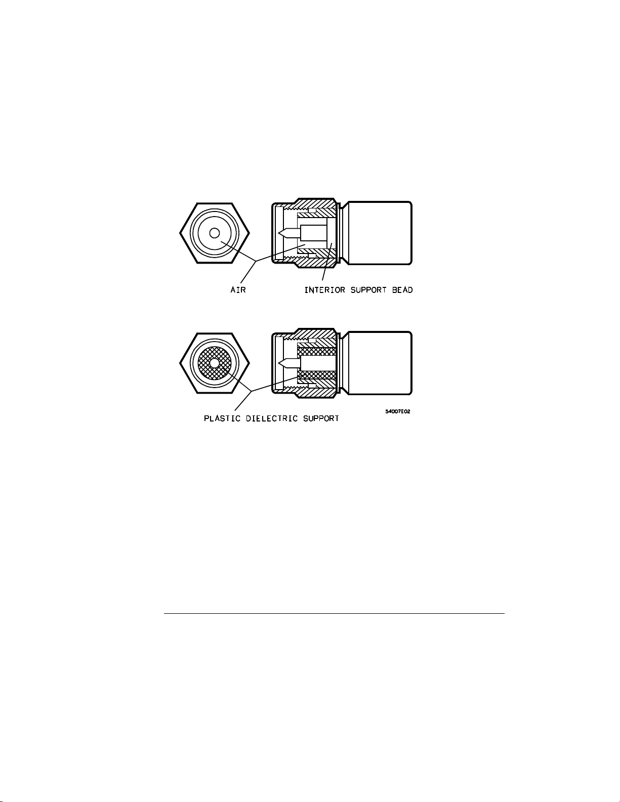
Figure 2-1
Care and Handling of Precision Connectors
Device Specifications
the entire length of the center conductor. In addition, the diameter of both the
center and outer conductors of an SMA connectors differ from that of a precision
3.5 mm connector.
If these precautions and recommendations are followed, SMA connectors can
be mated with 3.5 mm precision connectors without fear of expensive and time
consuming repairs.
SMA and a Precision 3.5 mm Connectors
When an SMA connector is mated with a precision 3.5 mm connector, the
connection exhibits a continuity mismatch (SWR), typically about 1.10 at
20 GHz. This mismatch is less than when precision 3.5 mm connectors are
mated. Keep this fact in mind when making measurements on SMA and
precision 3.5 mm coupled junctions.
2-5
Page 22
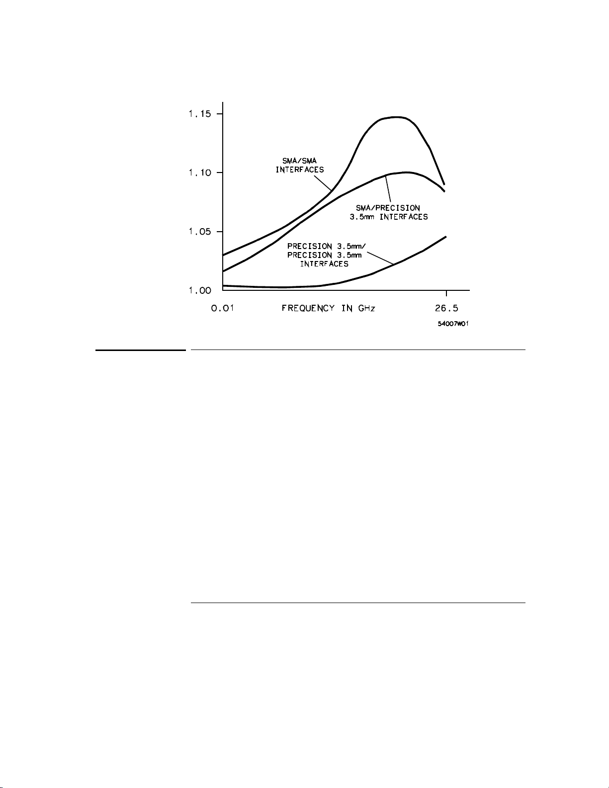
Figure 2-2
Care and Handling of Precision Connectors
Accuracy Considerations
Typical SWR of SMA and Precision 3.5 mm Connectors
Accuracy Considerations
Accuracy requires that 3.5 mm precision connectors be used. However, SMA
connectors can be used if special care is taken when mating the two, and all
connectors are undamaged and clean. Before each use, the mechanical
dimensions of all connectors must be checked with a connector gauge to make
sure that the center conductors are positioned correctly. All connections must
be made for consistent and repeatable mechanical (and therefore electrical)
contact between the connector mating surfaces.
Carefully study and practice all procedures in this chapter until you can
successfully perform them repeatedly. Accuracy and repeatability are critical
for good high frequency measurements. Note that the device connection
procedures differ in several important ways from traditional procedures used
in the industry. Agilent Technologies procedures have been developed through
careful experimentation.
2-6
Page 23

Care and Handling of Precision Connectors
Accuracy Considerations
Handling Precision 3.5 mm Connectors
• Precision 3.5 mm connectors must be handled carefully if accurate
calibrations and measurements are to be obtained.
• Store the devices in the foam-lined storage case when not in use.
• Avoid bumping or scratching any part of the mating surfaces.
• Be careful to align the center connectors.
• Check the alignment carefully before tightening the connector nuts.
• Use a torque wrench for all final connections in order to avoid
overtightening.
• Support the devices being used in order to avoid vertical or lateral force on
any connectors. This precaution is critical when using the airline, 6 cm "L",
or cables.
When Disconnecting Devices:
• Do not rock or bend any connections.
• Pull the connector straight out without unscrewing or twisting.
• Before storage, screw the connector nut all the way out to help protect the
surfaces, and use the plastic caps provided. These plastic caps can be taken
off easily by unscrewing, rather than pulling.
CAUTION Do not use a damaged or defective connector. It will damage any good
connector to which it is attached. Throw the connector away or have it
repaired.
A connector is bad if it fails either the visual or mechanical examinations or
when an experienced operator cannot make repeatable connections. The time
and expense involved in replacing channel connectors warrants considerable
caution when any connector might be less than perfect.
If any doubts exist about a connector, call your Agilent Technologies
representative. Agilent Technologies field offices offer limited professional
advice and have access to the factory for information.
2-7
Page 24

Care and Handling of Precision Connectors
Visual Inspection
Visual Inspection
Always begin a calibration with a careful visual inspection of the connectors,
including the test set connectors to make sure they are and undamaged.
CAUTION
Make sure that you and your equipment are grounded before touching any
center conductor so you won't cause static electricity and create a potential
for electrostatic discharge. When using or cleaning connectors, be aware that
you are touching exposed center connectors that are connected directly to the
internal circuits of the oscilloscope. Touching the center conductor, especially
with a wiping or brushing motion, can cause an electrostatic discharge (ESD)
and severely damage these sensitive circuits.
Use an illuminated, 4-power magnifying glass for visual inspection.
1
Before you begin, make sure you and any equipment you are using are
grounded to prevent electrostatic discharge.
2
Examine the connectors first for obvious problems, such as deformed
threads, contamination, or corrosion.
3
Next concentrate on the mating surfaces of each connector. Look for
scratches, rounded shoulders, misalignment, or any other signs of wear
or damage.
4
Make sure that the surfaces are clean, free of dust and solvent residues.
Dirt or damage visible with a 4-power magnifying glass can cause
degraded electrical performance and possible connector damage. All
connectors should be repaired or discarded immediately.
Mechanical Inspection
Mechanical inspection of the connectors is the next step. This inspection
consists of using the appropriate male or female precision 3.5 mm connector
gauge to check the mechanical dimensions of all connectors, including those on
the test set. The purpose of doing this is to make sure that perfect mating will
occur between the connector surfaces. Perfect mating assures a good electrical
match and is very important mechanically to avoid damaging the connectors
themselves, especially on the oscilloscope.
2-8
Page 25

Care and Handling of Precision Connectors
Mechanical Inspection
Center Conductor
The critical dimension to be measured is the recession of the center conductor.
This dimension is shown as MP and FP in Figure 2-3 and Figure 2-4. No
protrusion of the center conductor's shoulder is allowable on any connector.
The maximum allowable recession of the center conductor shoulder is 0.003 in.
(0.08 mm) on all connectors, except those on the channel connectors.
On the channel connectors, not only is no protrusion allowable, the shoulder of
the center conductor must be recessed at least 0.0002 in. (0.005 mm). The
maximum allowable recession of the center conductor shoulder on the channel
connectors is 0.0021 in. (0.056 mm).
2-9
Page 26
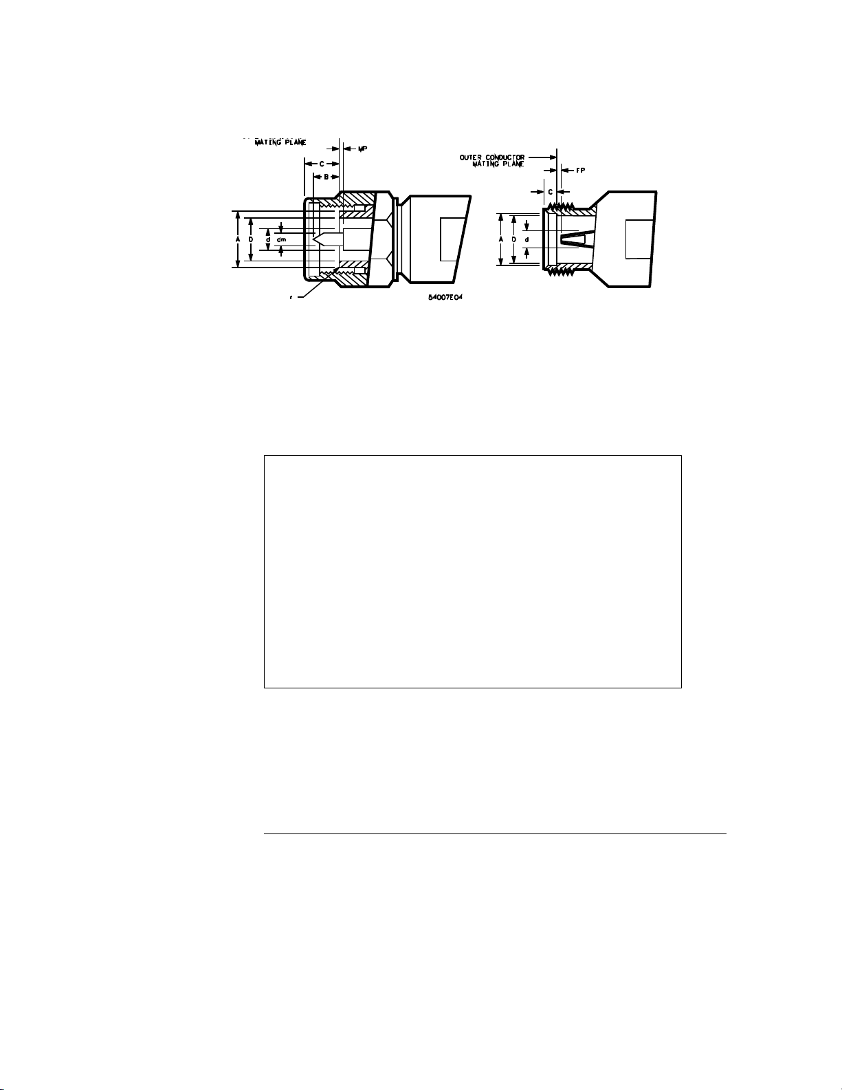
Figure 2-3
Care and Handling of Precision Connectors
Mechanical Inspection
D = inside diameter of the outer conductor
d = diameter of male/female center connector
A = outside diameter of outer conductor at the mating plane
r = corner relief for male connector
B = protrusion of the male contact pin tip beyond the outer conductor mating plane
C = recession of the outer conductor mating plane behind outer face of connector
MP = recession of male contact pin shoulder behind outer conductor mating plane
Male Connectors Female Connectors
inches millimeters inches millimeters
D = 0.1378 ± 0.0005 3.500 ± 0.013 D = 0.1378 ± 0.0005 3.500 ± 0.013
d = 0.0598 ± 0.0003 1.519 ± 0.008 d = 0.0598 ± 0.0003 1.519 ± 0.008
A = 0.1803 + 0.000
- 0.002
r = 0.003 0.08 r = 0.003 0.08
B = 0.085 +0.005
- 0.015
C = 0.120 ± 0.015 3.05 ± 0.38 C = 0.176 ± 0.002 1.93 ± 0.05
Mp = 0.00 + 0.003
- 0.000
dm = 0.037 + 0.000
- 0.001
Mechanical Dimensions of Connector Faces
4.580 + 0.00
- 0.05
2.16 + 0.13
- 0.38
0.000 + 0.08
- 0.00
0.94 + 0.00
- 0.03
A = 0.1807 + 0.002
- 0.000
N/A
Fp = 0.000 + 0.003
- 0.00
N/A
4.590 + 0.05
- 0.00
0.000 + 0.08
- 0.00
2-10
Page 27
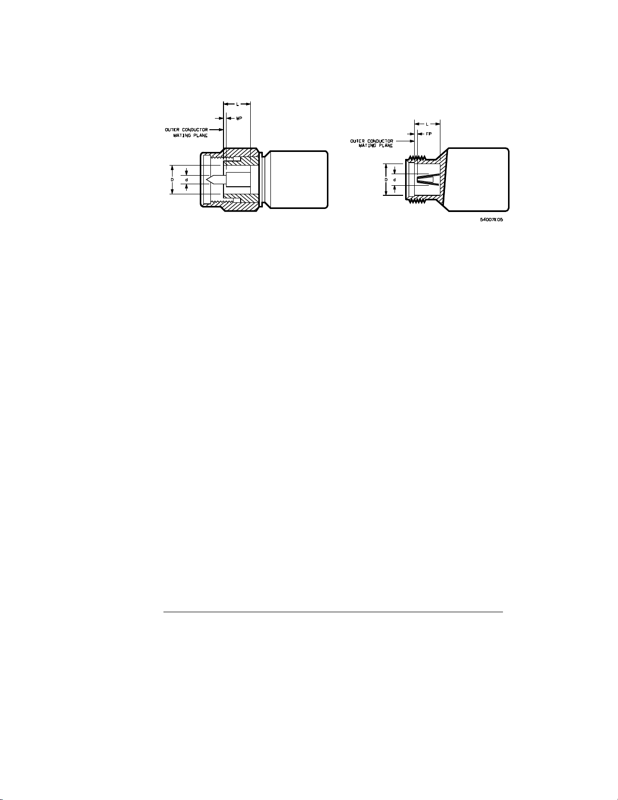
Figure 2-4
Care and Handling of Precision Connectors
Mechanical Inspection
Mechanical Dimensions of the Short Circuit
Outer Conductor
If any contact protrudes beyond the outer conductor mating plane, the contact
is out of tolerance and must be replaced. If the center conductor is not recessed
at least 0.0002 in. (0.005 mm), it is out of tolerance and must be replaced. In
both cases the out-of-tolerance connector will permanently damage any
connector attached to it. Destructive electrical interference will also result due
to buckling of the female contact fingers. This is often noticeable as a power
hole several dB deep occurring at about 22 GHz.
If any contact is recessed too far behind the outer conductor mating plane
(0.0021 in. 0.056 mm, except in test sets), poor electrical contact will result,
causing high electrical reflections. Careful gauging of all connectors will help
prevent this condition.
Before using the connector gauge to measure the connectors, visually inspect
the end of the gauge and the calibration block in the same way that you
inspected the connectors. Dirty or damaged gauge facings can cause dirty or
damaged connectors. Two connector gauges are available from Agilent
Technologies, one for each connector type, male and female. Refer to
Figure 2-5. A single gauge calibration block is used to zero both gauges; one end
protrudes for zeroing the male connector gauge. The part number for both
gauges, as well as the calibration block is 85052-80010.
Figure 2-5 to Figure 2-8 show how to use the connector gauges. Zero the gauge
with the calibration block. Refer to Figure 2-5. It is recommended that you zero
both gauges first, then measure each of the terminations and/or adapters that
will be used. Then, as the last step, measure the channel connectors.
Figure 2-7 and Figure 2-8 show how to measure precision 3.5 mm connectors.
Note that a plus (+) reading on the gauge indicates recession of the center
conductor and a minus (-) reading indicates protrusion. Since no protrusion of
either connector is allowable, readings for connectors within the allowable
2-11
Page 28
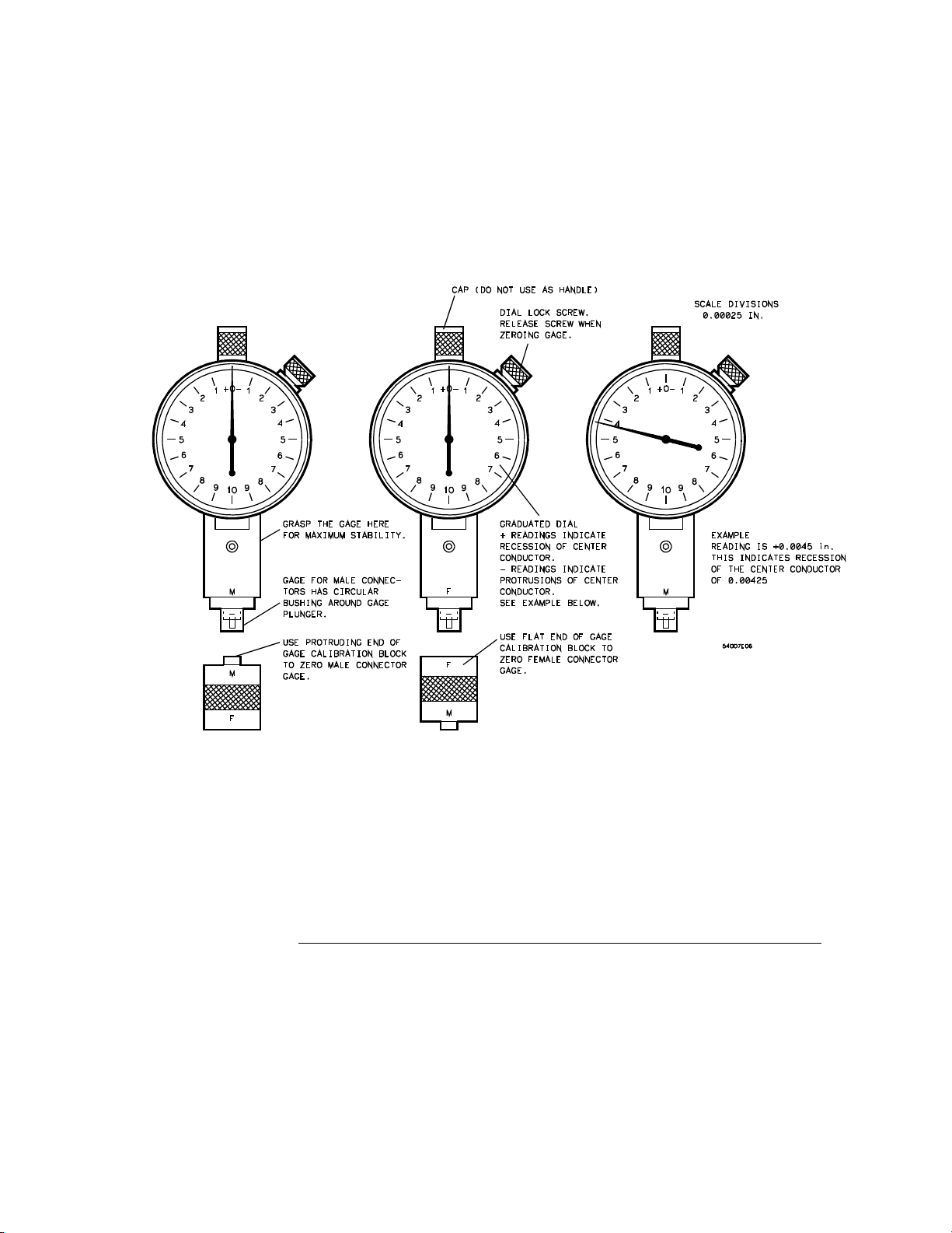
Figure 2-5
Care and Handling of Precision Connectors
Mechanical Inspection
range will be on the plus (+) scale of the gauge. Also note that the allowable
tolerance range for the test set connectors is different from the range for other
connectors. Both ranges are shown in Figure 2-7 and Figure 2-8. Before
measuring test set connectors, be sure that the power to the test set is off and
that you and your equipment are grounded to prevent electrostatic discharge.
Precision 3.5 mm Connector Gauges
2-12
Page 29
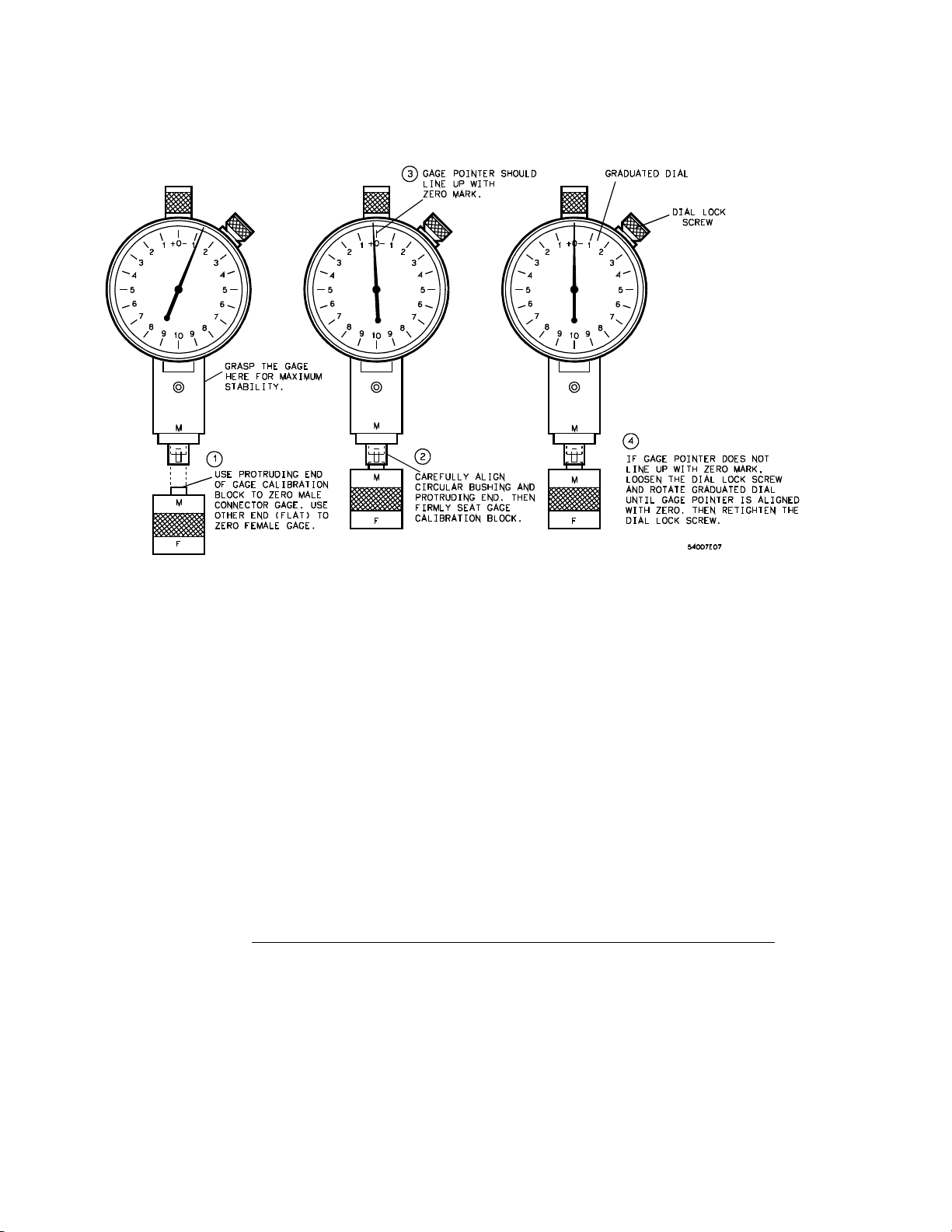
Figure 2-6
Care and Handling of Precision Connectors
Mechanical Inspection
Zeroing Precision 3.5 mm Connector Gauge
2-13
Page 30
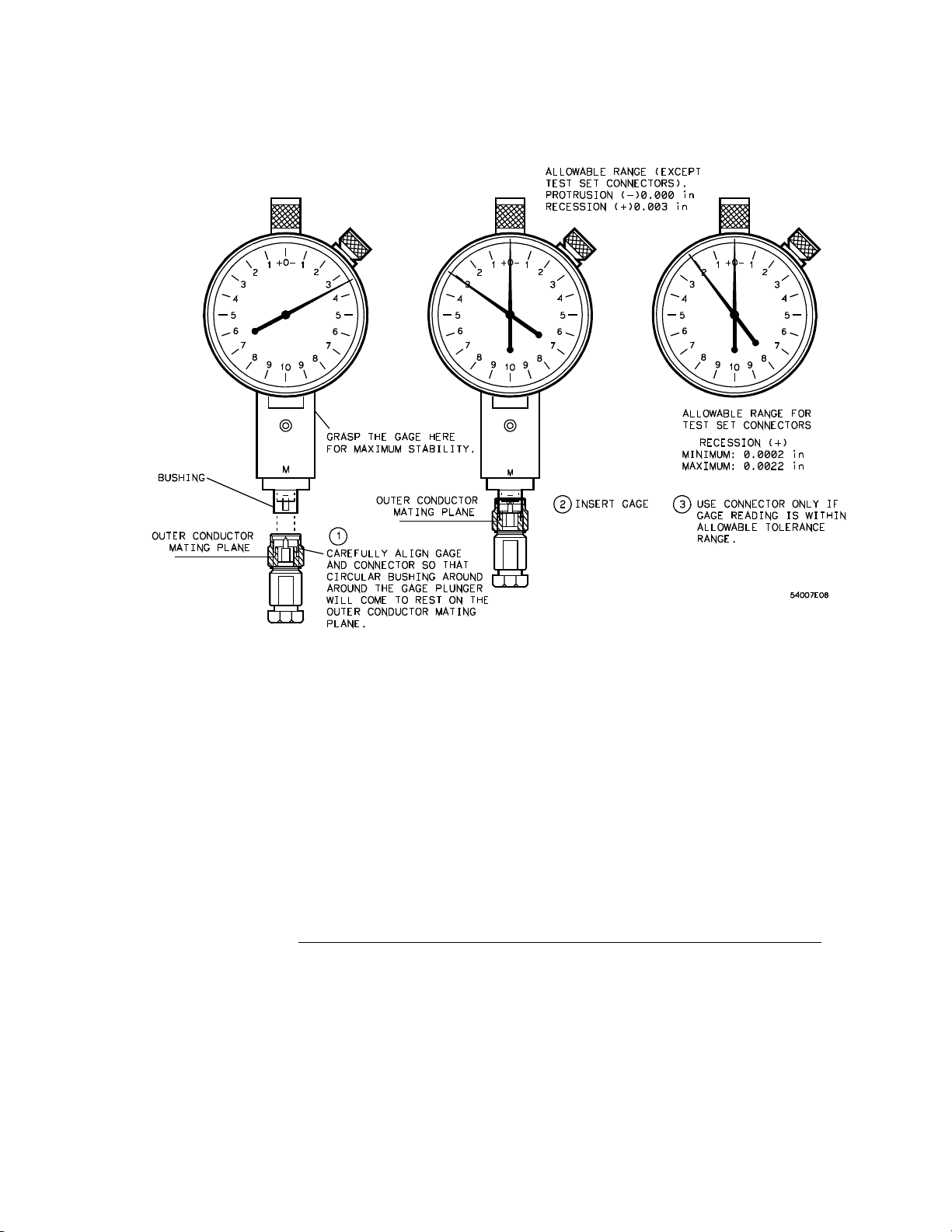
Figure 2-7
Care and Handling of Precision Connectors
Mechanical Inspection
Measuring Precision 3.5 mm Male Connectors
2-14
Page 31
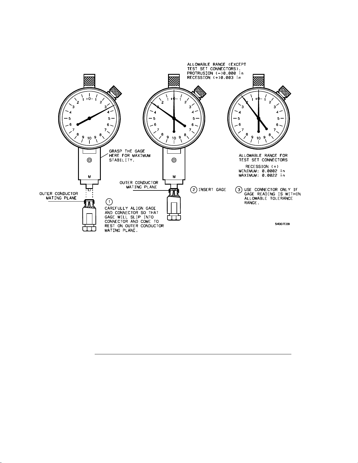
Figure 2-8
Care and Handling of Precision Connectors
Mechanical Inspection
Measuring Precision 3.5 mm Female Connectors
2-15
Page 32

Care and Handling of Precision Connectors
Connecting the Devices
Connecting the Devices
Figure 2-9 and Figure 2-10 illustrate Agilent Technologies’ recommended
procedures for making connections with the calibration devices. Notice that
these recommended procedures differ from traditional procedures used in the
microwave industry, especially the counter-rotation technique and procedure
for connecting the airline.
The counter-rotation technique, recommended here, involves a slight rotation
of the termination or adapter just before the final tightening of the connector
nut. This eliminates the very small air wedge between the outer conductors that
frequently occurs when the body is held stationary during tightening, as it is in
the traditional procedure. The Agilent 54753A or Agilent 54754A plug-in
modules will detect the reflections caused by such small wedges.
The counter-rotation technique does not harm the connectors. The gold plating
on the outer conductor surface will become burnished in time. This is normal,
and as long as the surface remains smooth, the connector is still good. After
much use the gold plating may eventually wear through and expose the
beryllium-copper substratum. This too is normal, and if it is smooth the
connector is still good, although the beryllium-copper surface may oxidize if the
connector is used infrequently.
If the burnished surface is rough, scratched, rippled, or has other irregularities,
too much tightening force is being used. If the roughness is severe, the
connector is ruined and should not be used.
CAUTION
Damage can result if SMA connectors are overtightened to precision 3.5 mm
connectors. Use a torque wrench designed for SMA connectors, set to a 5 in lb
(60 N/cm). A torque wrench suitable for SMA connectors is available, Agilent
part number 8710-1582.
2-16
Page 33
Care and Handling of Precision Connectors
Connecting the Devices
Counter-Rotation Technique
The recommended Agilent Technologies counter-rotation technique is for
precision 3.5 mm connectors. Before making any connections to the channel
connectors, ground yourself with a grounded wrist strap. Also, it is good practice
to grasp the outer shell of the test port before you make any connections to the
channel connectors in order to discharge any static electricity on your body.
This is the most effective single safeguard to prevent ESD damage to your
instruments.
If the device has a retractable connector nut, fully retract the nut before
1
mating the connectors. Carefully align the male and female contact pins
and slide the connectors straight together until the center and the two
outer conductors meet. Be careful not to twist or bend the contact pins.
You should feel a slight resistance as the connectors mate.
Make the preliminary connection by attaching the connector nut of the
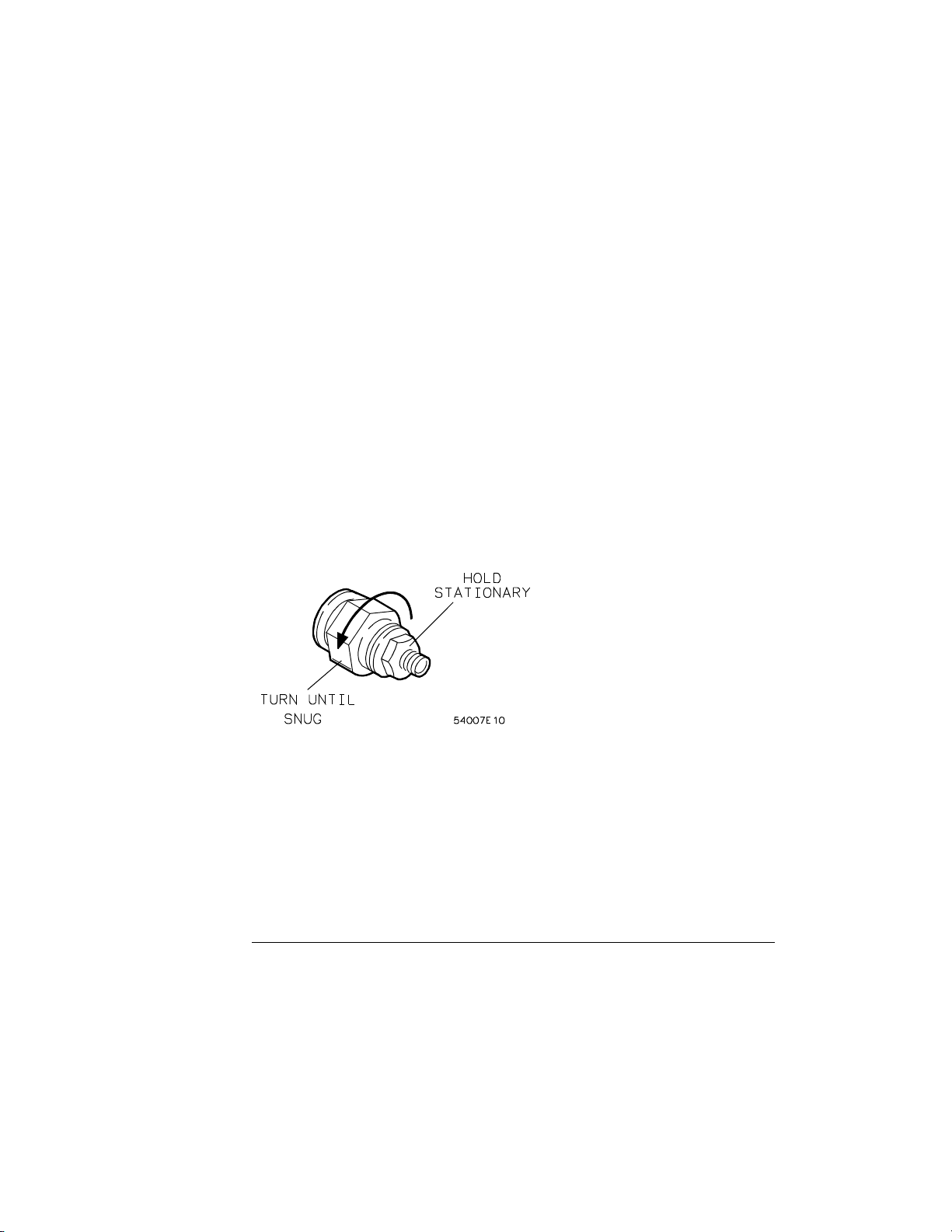
2
male connector to the female. The male connector is held stationary as
the female connector is tightened and draws the male pin into the
female connector. Refer to
Figure 2-9
. Any other method used may cause
the male pin to damage the female connector. Support the body of the
device and turn the connector nut until the mating surfaces make light
contact. Do not overtighten. All you want is a connection of the outer
conductors with gentle contact at all points of both mating surfaces.
Figure 2-9
Connecting 3.5 mm Devices
2-17
Page 34
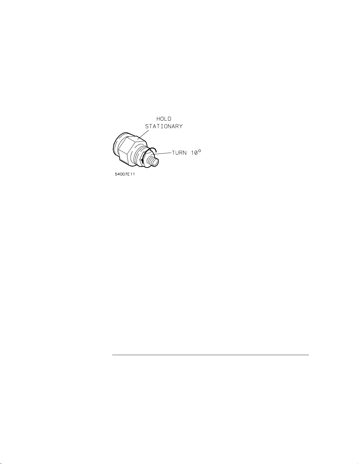
Figure 2-10
Care and Handling of Precision Connectors
Connecting the Devices
3 When you are satisfied with this preliminary connection, use the
following counter-rotation technique to eliminate air wedges between
the mating planes. Refer to
Figure 2-10
. If the calibration device is male,
hold the connector nut firmly. Very slowly rotate the body of the device
about 10-20 ° counterclockwise. Note that this slight rotation or
backwiping is sufficient. Greater rotation does not improve electrical
performance and increases wear on the connector surfaces.
Counter-rotation Technique
If the calibration device is female (the connector nut is on the TDR plug-in
module), very slowly rotate both the connector nut and the body of the device
clockwise 10-20 ° (counterclockwise rotation will loosen the connection).
Light, smooth frictional resistance felt during the counter-rotation indicates you
have made the preliminary connection correctly and that the counter-rotation
technique has been successful. Roughness felt during counter-rotation
indicates either that the connectors are damaged or that there is roughness in
the connector nut/thread contact. Inspect both connectors again before
proceeding, to make sure that the roughness is due to roughness in the
connector nut interface rather than on the connector mating planes.
4 Tighten the connector nut finger tight, allowing the device to turn with
the nut if it tends to do so. A small rotation of the body of the device at
this point is acceptable and tends to occur naturally.
5 Use a torque wrench to make the final connection. Use of the torque
wrench assures the final connection will be tight enough for optimum
electrical performance, but not so tight as to distort or damage the
connectors.
2-18
Page 35

Care and Handling of Precision Connectors
Connecting the Devices
To disconnect, follow this procedure:
1 Loosen the connector nut on the male connector with the torque
wrench. Leave the connection finger tight.
2 While supporting the calibration device, gently unfasten the connectors
and pull the calibration device straight out of the channel connector.
Do not twist either the center conductor or the outer conductor housing
or exert lateral or vertical (bending) force on the connection.
Some precision 3.5 mm female connector fingers are very tight and can pull the
center pin of their mates out past specifications as they are disconnected. If such
a male pin is inserted into a female connector, it can cause considerable damage
by pushing the female center conductor back too far. Be aware of this possibility
and check all connectors before mating them again.
2-19
Page 36

2-20
Page 37

3
Setup Channel Menu
Page 38

Setup Channel Menu
What you’ll find in this chapter
This chapter describes the Setup Channel menu. A key tree and description of the
available functions are included.
CAUTION
The input circuits can be damaged by electrostatic discharge (ESD). Therefore,
avoid applying static discharges to the front-panel input connectors. Before
connecting any coaxial cable to the connectors, momentarily short the center
and outer conductors of the cable together. Avoid touching the front-panel
input connectors without first touching the frame of the instrument. Be sure
the instrument is properly earth-grounded to prevent buildup of static charge.
The top left keys of the plug-in module are the Channel keys. These keys give
you access to the Setup Channel menu for each input. The Setup Channel menu
is displayed on the right side of the screen when the Channel key is pressed.
There are several types of softkeys available. A description of the different
softkeys and their functions is provided in the Agilent 83480A, 54750A User’s
Quick Start Guide supplied with the mainframe.
3-2
Page 39
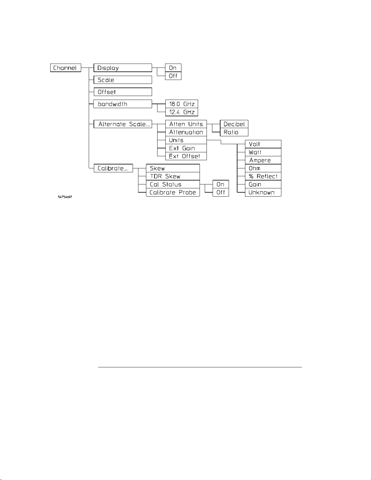
Figure 3-1
Setup Channel Menu
Electrical Setup Channel menu.
3-3
Page 40

Setup Channel Menu
Displaying the Setup Channel menu
Displaying the Setup Channel menu
To display the Setup Channel menu, press the Channel key.
Display
The Display softkey turns the channel display off and on. When the channel
display is on, a waveform is displayed for that channel, unless the offset is
adjusted so the waveform is clipped off of the display or the instrument is not
triggering.
The channel number, vertical scaling, and offset are displayed at the bottom left
of the waveform area. They remain on the display until the channel is turned
off, or an automatic measurement is performed. The automatic measurement
results share the same area of the display as the channel setups.
When the channel display is off, the waveform display for that channel is turned
off, pulse parameter measurements are stopped and acquisition on that channel
is stopped, unless it is needed as an operand for waveform math functions or
TDR/TDT responses.
Even though the channel display is off, you can still use the plug-in as a function
source in the Math menu or as a source for four normalize, differential, or
common mode responses. However, the instrument will not trigger unless one
or more of the other channel displays are turned on, or unless a math function
or TDR/TDT response is using one of the channels.
Key Path Channel Display
Scale
The Scale softkey controls the vertical scaling of the waveform. If the fine mode
is off, then the knob and arrow keys change the vertical scaling in a 1-2-5
sequence. When fine mode is on, the knob and arrow keys change the vertical
scaling in 1 mV increments. You can also use the keypad to enter values in 1 mV
increments, independent of the fine mode selection.
The units the scale is displayed in depend on the unit of measure selected with
the Units softkey. The choices for units are volts, watts, amperes, ohms, %
reflect, gain, or unknown.
3-4
Page 41

When the ohm, % reflect, or gain units are selected, the control changes to
Magnify scale. In this mode of operation, the TDR plug-in’s hardware scale
behaves as it would when the units mode is selected for all stimulus except for
differential or common mode.
If the TDR/TDT stimulus is set to differential or common mode, the control also
changes to Magnify scale. However, the hardware scale is set so that the
displayed waveform is never clipped. The Magnify scale control is a software
scaling control.
Key Path Channel Scale
Offset
The Offset softkey moves the waveform vertically. It is similar to the position
control on analog oscilloscopes. The advantage of digital offset is that it is
calibrated. The offset voltage is the voltage at the center of the graticule area,
and the range of offset is 500 mV. You can use the knob, arrow keys, or keypad
to change the offset setting. The fine mode also works with offset.
When an Agilent 54700-series active probe is used with the plug-in module and
is connected to the probe power connector adjacent to the channel input, the
offset control adjusts the external scale factor and offset of the hybrid inside
the active probe. A probe connected to the auxiliary power connector adjacent
to the trigger input will function, but the channel scale factor will not be adjusted
automatically.
The units the offset is displayed in depend on the unit of measure selected with
the Units softkey. The choices for units are volts, watts, amperes, ohms, %
reflect, gain, or unknown.
When the ohm, % reflect or gain units are selected, the control changes to
Magnify offset. In this mode of operation, the TDR plug-in’s hardware offset
behaves as it would when the units mode is selected for all stimulus except for
differential or common mode.
If the TDR/TDT stimulus is set to differential or common mode, the control also
changes to Magnify offset, however, the harrower scale is set so that the
displayed waveform is never clipped. The Magnify offset control is a software
offset control.
Setup Channel Menu
Offset
Key Path Channel Offset
3-5
Page 42

Setup Channel Menu
Bandwidth. . .
Bandwidth. . .
You can use the Bandwidth function to select either 12.4 GHz or 18 GHz
bandwidth. For the Agilent 54753A TDR plug-in module, channel 2 can be either
12.4 GHz or 20 GHz bandwidth.
Key Path Channel Bandwidth. . .
Alternate scale. . .
The Alternate Scale function allows you to change the units used to label the
vertical scale of the display. It also allows you to select the attenuation units
and the attenuation factor.
Key Path Channel Alternate scale . . .
Atten units
The Atten Units function lets you select how you want the probe attenuation
factor represented. The choices are either decibel or ratio. The formula for
calculating decibels is:
20
V
out
----------
V
or 10
in
P
out
----------loglog
P
in
The Atten Units function is not available when the units are set to ohm, % reflect,
or gain.
Attenuation
The Attenuation function lets you select an attenuation that matches the device
connected to the instrument. When the attenuation is set correctly, the
instrument maintains the current scale factors, if possible. All marker values
and voltage or wattage measurements will reflect the actual signal at the input
to the external device.
3-6
Page 43

The attenuation range is from 0.0001:1 to 1,000,000:1. When you connect a
compatible active probe to the probe power connector, adjacent to the
corresponding channel input, the instrument automatically sets the
attenuation. For all other devices, set the probe attenuation with the knob,
arrow keys, or keypad.
Refer to “Calibrating Voltage Probes” on page 3-12 for information on calibrating
to the tip of the probe.
The Attenuation function is not available when ohm, % reflect, or gain units are
selected.
Key Path Channel Alternate scale . . . Attenuation
Units
The Units function lets you select the unit of measure appended to the channel
scale, offset, trigger level, and vertical measurement values. For the plug-in
module, the units are volts, watts, amperes, ohms, % reflect, gain, or unknown.
Use volt for voltage probes, ampere for current probes, watt for optical-toelectrical (O/E) converters, and unknown when there is no unit of measure or
when the unit of measure is not one of the available choices. The gain selection
is only available when the channel has been chosen as a TDT destination.
The two additional choices, ohms and % reflect are selectable once a TDR/TDT
normalization and reference plane have been established (see the 54753A Setup
Menu or 54754A Setup Menu chapter under Establish normalization & ref plane
for more information). Use Ohms when TDR/TDT vertical scale units of ohms/
div are required for making measurements. Use % reflect when TDR/TDT
percentage of reflection units are required.
Setup Channel Menu
Alternate scale. . .
Key Path Channel Alternate scale . . . Units
Ext gain and Ext offset
When you select ampere, watt, or unknown, two additional functions become
available: External Gain and External Offset. These two additional functions
allow you to compensate for the actual characteristics of the probe rather than
its ideal characteristics. For example, you might have an amplified lightwave
converter with ideal characteristics of 300 V/W with 0 V offset. But, its actual
characteristics are 324 V/W with 1 mV of output offset. Therefore, set the
External Gain to 324 V/W and the External Offset to 1 mV.
3-7
Page 44

Setup Channel Menu
Calibrate . . .
Key Path Channel External scale . . . Units Volt Ext gain or Ext Offset
Channel External scale . . . Units Watt Ext gain or Ext Offset
Channel External scale . . . Units Unknown Ext gain or Ext Offset
Calibrate . . .
The calibrate menu allows you to null out any skew between probes or cables
and to check the present calibration status of the instrument.
Key Path Channel Calibrate . . .
Skew
The Skew function changes the horizontal position of a waveform on the display.
The Skew function has a range of approximately 100 µs. You can use skew to
compensate for differences in cable or probe lengths. It also allows you to place
the triggered edge at the center of the display when you are using a power
splitter connected between the channel and trigger inputs. Another use for
skew is when you are comparing two waveforms that have a timing difference
between them. If you are more interested in comparing the shapes of two
waveforms rather than the actual timing difference between them, you can use
Skew to overlay one waveform on top of the other waveform.
To adjust the skew on two channels
1. Turn both channels on and overlay the signals vertically.
2. Expand the time base, so the rising edges are about a 45 degree angle.
3. Adjust the skew on one of channels, so that the rising edges overlap at the
50 percent points.
Key Path Channel Calibrate . . . Skew
3-8
Page 45

Setup Channel Menu
Calibrate . . .
TDR Skew
The TDR Skew function changes the position of the TDR step. The TDR Skew
function has a range of ≅ ±400 pS. The units of the function are shown in % of
the maximum range, or ±100%. The Skew function and the TDR Skew function
differ in that Skew moves the acquired waveform with respect to the trigger,
while the TDR Skew function moves the TDR step with respect to the trigger.
TDR Skew can be used to align the TDR steps of the two TDR channels for more
accurate differential TDR measurements when cable or probe lengths are
different.
To deskew the two TDR channels
1. Turn on both channels and overlay the signals vertically with no cables attached.
2. Expand the time base so the rising edges are about a 45 degree angle.
3. Adjust the TDR skew on one of the channels, so that the rising edges overlap at
the 50 percent points.
4. Attach the cables. If the cables differ in length, then the waveforms will not
overlay each other.
5. Using the ∆Time auto measurement or manual markers, measure the ∆time (the
skew) between the TDR channels.
6. Adjust the channel Skew for the channel whose waveform is to the right of the
other channels waveform until the skew is ½ of the measured ∆time.
7. Adjust the TDR Skew for the right most waveform until the remaining skew is ≅ 0.
Key Path Channel Calibrate . . . TDR Skew
3-9
Page 46
Setup Channel Menu
Calibrate . . .
Cal status
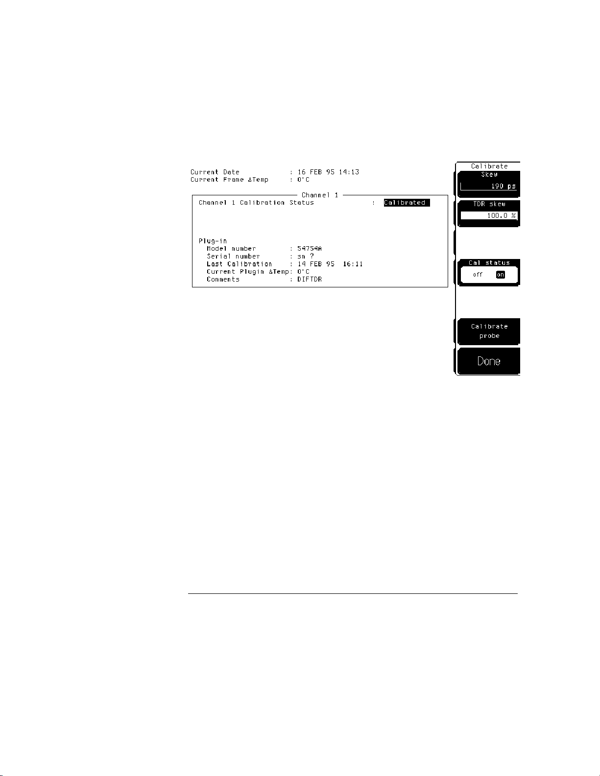
The Cal Status function displays a screen similar to Figure 3-8.
Key Path Channel Calibrate Cal Status
Figure 3-8
A typical Cal Status display.
Current Date This is the current date and time. You can compare this to
the last plug-in module calibration time. That way you will know how long
it has been since the last plug-in module calibration was performed.
Current Frame ∆Temp This is the temperature change on the inside of
the instrument since the last mainframe calibration was performed. A
positive number indicates how many degrees warmer the mainframe is
currently as compared to the temperature of the mainframe at the last
mainframe calibration.
3-10
Page 47

Channel 1 Calibration Status The instrument displays Calibrated
when the plug-in module has been calibrated in the current mainframe slot
otherwise the instrument displays Uncalibrated. Once a plug-in is
calibrated, the temperature difference (∆Temp) between when the plug-in
was calibrate and the current temperature is displayed. The plug-in module
will met dc accuracy specifications as long as the ∆Temp is within the range
of -5 °C to +5 °C. Also displayed, is a list of the plug-in module’s model
number, serial number, date of last calibration, and time of last calibration.
Calibrate probe
Connect a voltage probe to the plug-in and then press:
Calibrate probe
Continue
The instrument calibrates to the tip of the probe by setting the probe
attenuation to the actual attenuation ratio of the probe. The instrument also
automatically compensates for any offset that the probe may introduce.
Key Path Channel Calibrate Calibrate probe Continue
Setup Channel Menu
Calibration Procedures
Calibration Procedures
What you’ll find in this section
This sections contains procedures for performing:
• a plug-in module vertical calibration
• calibration of voltage probes
• calibration of other devices
3-11
Page 48

Setup Channel Menu
Performing a Plug-in Module Vertical Calibration
Performing a Plug-in Module Vertical Calibration
1
To perform a plug-in module vertical calibration, press:
Utility
Calibrate . . .
Calibrate plug-in. . .
2
Select the plug-in module to be calibrated by pressing:
1 and 2 or 3 and 4
3
Start the calibration procedure by pressing:
Start cal
4
Follow the on screen instructions.
Calibrating Voltage Probes
Because the mainframe’s CAL signal is a voltage source, you can let the
instrument compensate for the actual characteristics of your probe by letting
the instrument calibrate to the tip of the probe.
Performing the Calibration
To calibrate a voltage probe to the probe tip, set the instrument as follows:
Atten units ratio
Units Voltage
Calibrate Probe
The instrument automatically calibrates to the tip of the probe, sets the probe
attenuation and compensates for any probe offset.
Calibrating Other Devices
Because the mainframe’s CAL signal is a voltage source, it cannot be used to
calibrate to the probe tip when the units are set to ampere, watt, or unknown.
Instead, set the external gain and external offset to compensate for the actual
characteristics of the probe or device. If you do not know the actual
characteristics, you can refer to the typical specifications that came with the
probe or device.
3-12
Page 49

Setup Channel Menu
Calibrating Voltage Probes
Performing the Calibration
To compensate for the actual characteristics of the probe or device, set the
instrument as follows:
Atten units ratio
Attenuation 1:1
Units Ampere
Ext gain actual gain characteristics of the probe or device.
Ext offset offset introduced by the probe or device.
(Watt or unknown)
3-13
Page 50

3-14
Page 51

4
Agilent 54753A TDR/TDT Setup Menu
Page 52

Agilent 54753A TDR/TDT Setup Menu
What you’ll find in this chapter
This chapter describes the TDR/TDT Setup menu. A key tree and description of the
available functions is included.
CAUTION
The input circuits can be damaged by electrostatic discharge (ESD).
Therefore, avoid applying static discharges to the front-panel input connectors.
Before connecting any coaxial cable to the connectors, momentarily short the
center and outer conductors of the cable together. Avoid touching the frontpanel input connectors without first touching the frame of the instrument. Be
sure the instrument is properly earth-grounded to prevent buildup of static
charge.
The top right key of the plug-in module is the TDR/TDT Setup key. This key gives
you access to the TDR/TDT Setup menu. The TDR/TDT Setup menu is displayed
on the right side of the screen when the TDR/TDT Setup key is pressed. There
are several types of softkeys available.
4-2
Page 53
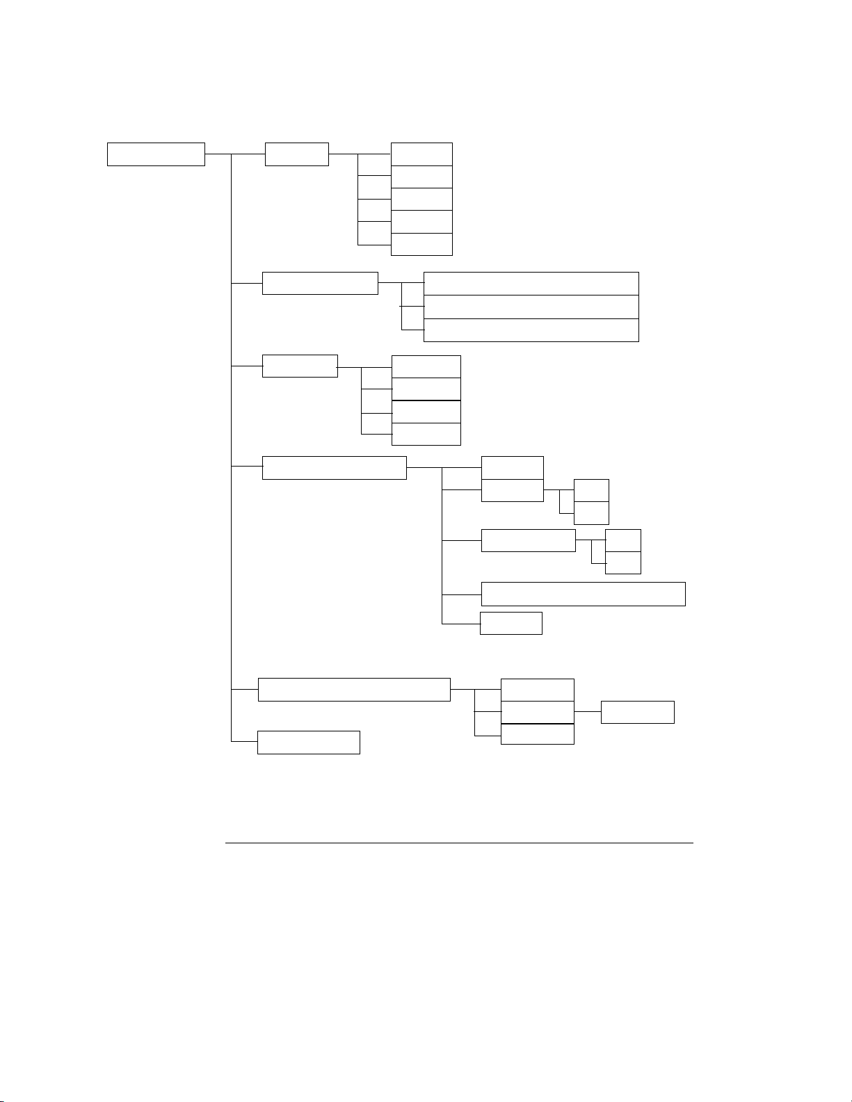
Figure 4-1
Agilent 54753A TDR/TDT Setup Menu
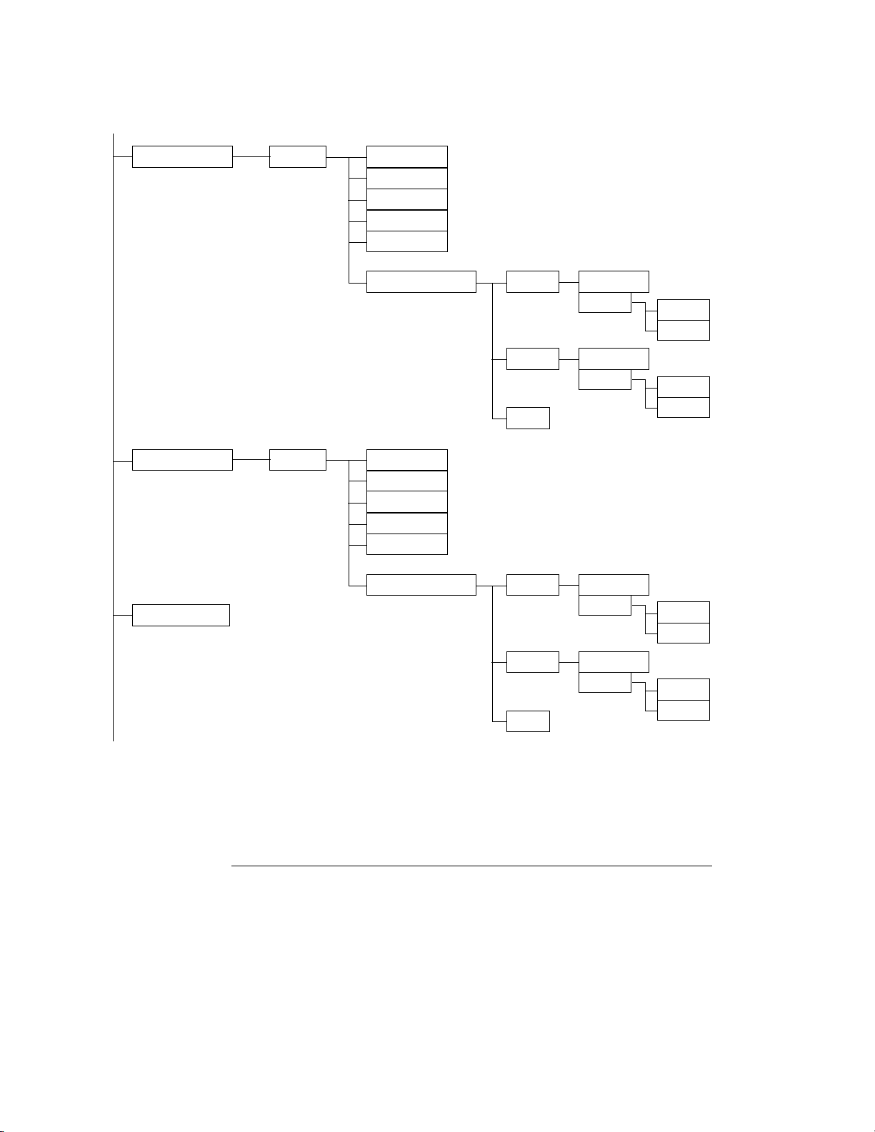
TDR/TDT Setup Stimulus
TDR/TDT help . . .
TDT 1 dest
Normalize response . . .
Off
On
External
Cancel
Enter
Single ended TDR/TDT
Differential common mode TDR/TDT
Done
channel 2
none
Cancel
Enter
Risetime
TDR/TDT
TDR normalize
TDR
TDT
off
on
TDR/TDT Setup Menus
TDR rate automatic . . . (250 kHz)
Preset TDR/TDT
Establish normalization & ref plane
Done
automatic
manual TDR rate
Done
4-3
Page 54

Table 4-1
Agilent 54753A TDR/TDT Setup Menu
Displaying the TDR/TDT Setup Menu
Displaying the TDR/TDT Setup Menu
To display the TDR/TDT Setup menu, press the TDR/TDT Setup key on the TDR
plug-in module.
Stimulus
Pressing the Stimulus softkey produces a pull-down menu used to turn on or
turn off the TDR step. The Agilent 54753A is a single-ended TDR plug-in and
has one TDR stimulus channel. The following table contains a list of the available
stimulus menu choices and their descriptions.
Stimulus Menu Choices
Stimulus Description
off Turns the TDR step off and disables the TDR measurement system.
on Turns the TDR step on and enables the TDR measurement system.
external This setup provides control for and requires an external step
Key Path TDR/TDT Setup Stimulus
generator before measurements can be made.
TDT 1 dest
The TDT 1 dest softkey only appears when the Stimulus is set to on or external.
Pressing the TDT 1 dest softkey produces a pull-down menu used to select the
channel used as the destination channel for TDT measurements. The choices
available for this pull-down menu depend on the other TDR or electrical plugin, if any, in the mainframe.
Any electrical channel is a valid TDT destination channel. If external stimulus
is selected, the TDT destination may not be set to the currently defined TDR
destination channel.
4-4
Page 55

If no other valid TDT destination channels are available, then "none" is the only
choice. If a TDT destination other than none is selected, then the Preset
TDR/TDT control will turn on and preset the TDT destination channel.
Key Path TDR/TDT Setup TDT 1 dest
TDR 1 dest
The TDR 1 dest softkey only appears when the stimulus is set to external.
Pressing the TDR 1 dest softkey produces a pull-down menu used to select the
channel used as the destination channel for TDR measurements. Any electrical
channel is a valid TDR destination channel. The TDR destination may not be
set to the currently defined TDT destination.
Key Path TDR/TDT Setup TDR 1 dest
Normalize response . . .
Agilent 54753A TDR/TDT Setup Menu
TDR 1 dest
The Normalize response function allows you to change the risetime of the
normalized step, to select TDR and TDT normalization, to turn on or off the
display of the normalized TDR or TDT trace, to change the scaling of the
normalized trace, and to establish the normalization filter values and reference
plane.
Risetime
The Risetime function allows you to change the normalized step’s risetime from
a minimum of
10 ps
or
time per division (s/div) 10 divisions×
min 8 points
whichever is greater, to a maximum of
max 5 time per division (s/div)×=
------------ ------------- ------------- ---------- ------------- ------------- ------------- ------
×=
record length
4-5
Page 56

Agilent 54753A TDR/TDT Setup Menu
Normalize response . . .
While the TDR step’s risetime applied to the system under test is fixed, the
measured response has a set of mathematical operations applied to it. These
mathematical operations effectively change the displayed response to the
system just as if a different TDR step risetime had actually been applied. This
allows you to select a risetime for TDR/TDT measurements that is close to the
actual risetime used in your system. This risetime value applies to both TDR
and TDT normalized channels. For more information on normalization, see the
chapter titled Improving Time Domain Network Measurements.
Key Path TDR/TDT Setup Normalize response . . . Risetime
TDR/TDT
The TDR/TDT function is used to select between TDR and TDT for normalization.
Both TDR and TDT channels can be normalized. This control selects which
normalized trace is referred to for the following controls. Before TDT
normalization can be done, you must select a TDT destination (TDT 1 dest).
Key Path TDR/TDT Setup Normalize response . . . TDR/TDT
TDR or TDT normalize
The TDR normalize function is available if the TDR mode is selected by using the
previous control; otherwise, the TDT normalize function is available. In either
case, this function turns on or off the display of the normalized trace. The TDR
and TDT normalization functions can be on at the same time.
Key Path TDR/TDT Setup Normalize response . . . TDR normalize
Normalize scaling . . .
The Normalize scaling function is used when vertical and horizontal scaling of
the normalized response is required that is independent from that of the source
channel. This function only appears when TDR or TDT normalize is set to on.
Key Path TDR/TDT Setup Normalize response . . . Normalize scaling . . .
Vertical There are two choices for vertical mode: track source and manual.
The track source mode sets the control of the vertical scaling for the
normalized trace to that of the source channel. When manual mode is
selected, the Y Scale and Y Offset menus appear allowing you to
independently change the vertical scale and offset of the normalized trace.
Key Path TDR/TDT Setup Normalize response . . .Normalize scaling . . . Vertical
4-6
Page 57

Agilent 54753A TDR/TDT Setup Menu
Normalize response . . .
Horizontal There are two choices for horizontal mode: track source and
manual. The track source mode sets the control of the horizontal scaling
for the normalized trace to that of the source channel. When manual mode
is selected, the Y Scale and Y Position menus appear allowing you to
independently change the horizontal scale and position for the normalized
trace.
Key Path TDR/TDT Setup Normalize response . . .Normalize scaling . . . Horizontal
Establish normalization & ref plane
The Establish normalization & ref plane function establishes the filter values used
to normalize a channel and to set the reference plane for TDR and TDT
measurements. This function must be performed separately for TDR and TDT
modes. The normalization and reference plane must be re-established when
power is lost or when the instrument is turned off. However, the values used for
normalization and reference plane calculations can be stored to and re-loaded
from disk. (See the Disk Menu chapter in the Agilent 83480A, Agilent 54750
User’s Guide for more information.)
The normalization filter values and reference plane become invalidated when the
timebase scale, record length or channel bandwidth is changed. Also, the
normalization process will not be able to remove small synchronous noise in the
channels baseline if the timebase position is changed. For most measurements
this error is very small.
The reference plane must be established before ohm, % reflect or gain units are
selectable for the channel. Also, the Reference ref plane
available in the Marker menu.
The function steps you through the normalization and reference plane
procedure for the selected measurement type. The procedure steps are
displayed at the top of the screen. The items required for calibration are shown
in Tabl e 4-2 .
function is not
4-7
Page 58

Agilent 54753A TDR/TDT Setup Menu
TDR rate automatic . . . (250 kHz)
Table 4-2
Establish normalization & ref plane Hardware Requirements
Measurement Requirements
TDR 50 ohm 3.5 mm SMA terminator
3.5 mm SMA short
TDT 1 or 2 each 3.5 mm SMA cables
3.5 mm barrel connector
Key Path TDR/TDT Setup Normalize response . . . Establish normalization & ref plane . . .
TDR rate automatic . . . (250 kHz)
The TDR rate automatic . . . (250 kHz) function allows you to manually or
automatically select the repetition rate of the TDR step. The range of values
for manual mode selection are from 50 Hz to 250 kHz repetition rate using a
1-2-5 sequence. When this function is set to automatic, the TDR step repetition
rate varies automatically as the Time base Scale is changed to keep multiple
steps off screen. As the TDR rate decreases, TDR measurements can be made
on longer transmission lines.
Key Path TDR/TDT Setup TDR rate automatic
Key Path TDR/TDT Setup TDR rate manual
Preset TDR/TDT
The Preset TDR/TDT function prepares the oscilloscope for making TDR/TDT
measurements by automatically setting several menu fields. The TDR preset
feature appears in the TDR/TDT Setup menu once a stimulus has been selected.
The menus that are affect by this feature are shown in Table 4-3.
4-8
Page 59

Table 4-3
Agilent 54753A TDR/TDT Setup Menu
Preset TDR/TDT
Preset TDR/TDT Configuration
Menu Menu Item Set To
Acquisition Averaging on
Best Flatness
Time Base Scale 500.0 ps/div
Position Set to a value which places the
incident edge on screen.
Channel 1 Setup Display on
Scale 100 mV/div
Offset 200.0 mV (for Stimulus on)
0.0 mV (form Stimulus external)
Bandwidth 12.4 GHz (for Stimulus on)
18.0 GHz (for Stimulus external)
Attenuation units ratio
Attenuation 1.000 : 1
Key Path TDR/TDT Setup Preset TDR/TDT
4-9
Page 60

4-10
Page 61

5
Agilent 54754A TDR/TDT Setup Menu
Page 62

Agilent 54754A TDR/TDT Setup Menu
What you’ll find in this chapter
This chapter describes the Agilent 54754A TDR/TDT Setup menu. A key tree and
description of the available functions is included.
CAUTION
The input circuits can be damaged by electrostatic discharge (ESD).
Therefore, avoid applying static discharges to the front-panel input connectors.
Before connecting any coaxial cable to the connectors, momentarily short the
center and outer conductors of the cable together. Avoid touching the frontpanel input connectors without first touching the frame of the instrument. Be
sure the instrument is properly earth-grounded to prevent buildup of static
charge.
The top right key of the plug-in module is the TDR/TDT Setup key. This key gives
you access to the TDR/TDT Setup menu. The TDR/TDT Setup menu is
displayed on the right side of the screen when the TDR/TDT Setup key is pressed.
There are several types of softkeys available.
5-2
Page 63
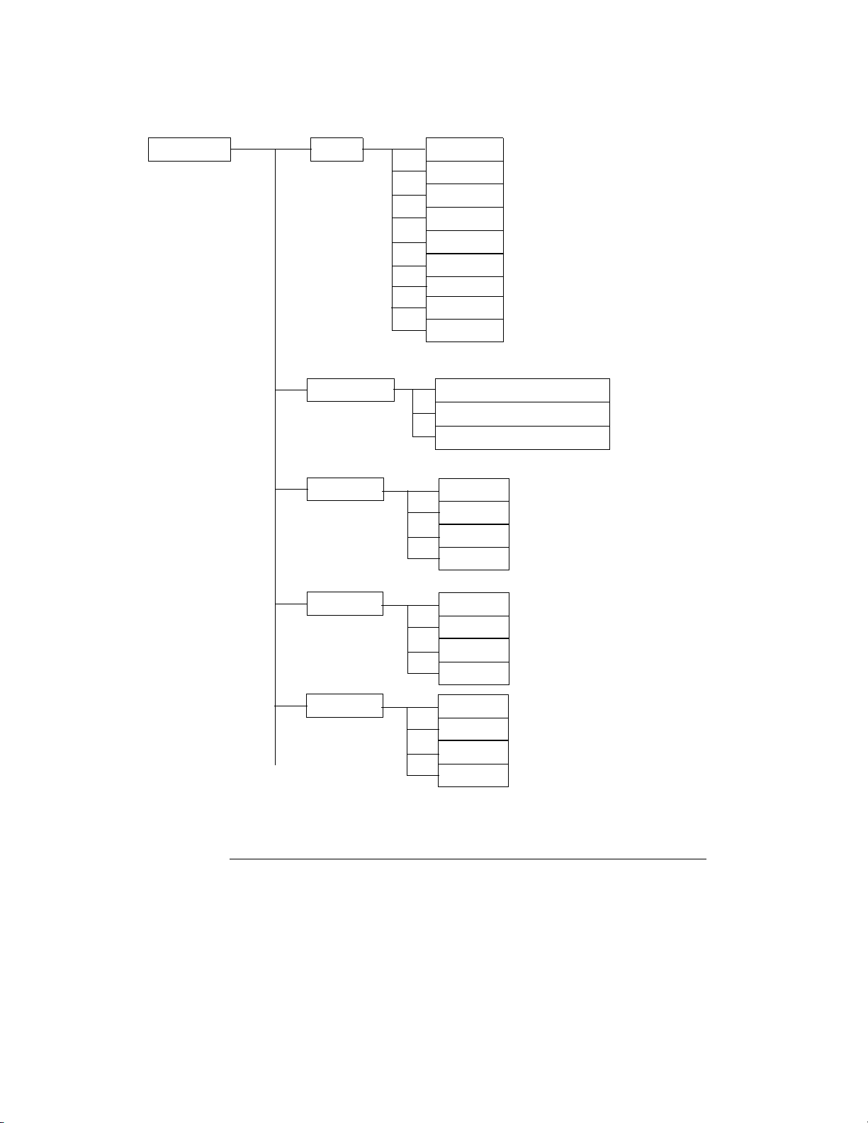
Figure 5-1
Agilent 54754A TDR/TDT Setup Menu
TDR/TDT Setup Stimulus
TDR/TDT help . . .
TDT 1 dest
Off
1 only
2 only
1 and 2
differential
common mode
external
Cancel
Enter
Single ended TDR/TDT
Differential common mode TDR/TDT
Done
channel 2
none
Cancel
Enter
TDT 2 dest
TDR 1 dest
channel 1
none
Cancel
Enter
channel 2
none
Cancel
Enter
5-3
Page 64
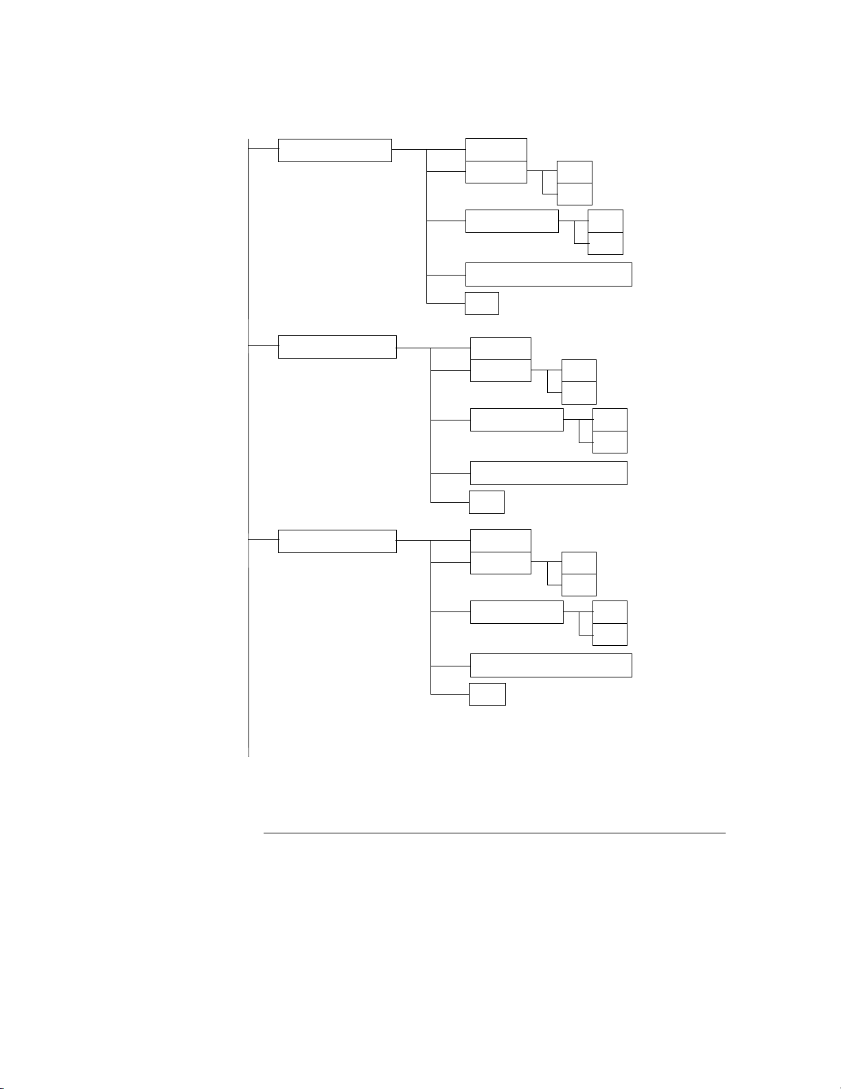
Agilent 54754A TDR/TDT Setup Menu
Normalize response . . .
Normalize 1 response . . .
Normalize 2 response . . .
Risetime
TDR/TDT
TDR normalize
Establish normalization & ref plane
Done
Risetime
TDR/TDT
TDR normalize
Establish normalization & ref plane
Done
Risetime
TDR/TDT
TDR
TDT
off
on
TDR
TDT
off
on
TDR
TDT
5-4
TDR normalize
Establish normalization & ref plane
Done
off
on
Page 65
TDR response 1 . . . Response off
differential
common mode
Cancel
Enter
Agilent 54754A TDR/TDT Setup Menu
Response scaling . . . Vertical
TDR response 2 . . . Response off
differential
common mode
Cancel
Enter
Response scaling . . . Vertical
Establish ref plane
Horizontal
Done
Horizontal
Done
track source
manual
track source
manual
track source
manual
track source
manual
Y Scale
Y Offset
X Scale
X Position
Y Scale
Y Offset
X Scale
X Position
5-5
Page 66

Agilent 54754A TDR/TDT Setup Menu
TDR rate automatic . . . (250 kHz)
Preset TDR/TDT
TDR/TDT Setup Menu.
automatic
manual
Done
TDR rate
5-6
Page 67

Table 5-1
Agilent 54754A TDR/TDT Setup Menu
Displaying the TDR/TDT Setup Menu
Displaying the TDR/TDT Setup Menu
To display the TDR/TDT Setup menu, press the TDR/TDT Setup key on the TDR
plug-in module.
Stimulus
Pressing the Stimulus softkey produces a pull-down menu used to turn on or
turn off the TDR step. The differential TDR plug-in has two TDR channels. The
following table contains a list of the available stimulus menu choices and their
descriptions.
Stimulus Menu Choices
Stimulus Description
off Turns the TDR steps off for both TDR channels and the TDR
measurement system off.
1 only Turns the TDR step on for channel 1 only and enables the TDR
measurement system.
2 only Turns the TDR step on for channel 2 only and enables the TDR
measurement system.
1 and 2 Turns the TDR steps on for both channels. This mode is used to
make two independent single-ended TDR measurements.
differential Turns the differential TDR steps on for both channels . The step for
channel 1 is a positive going step while the step for channel 2 is
effectively a negative going step. This mode is used to make
differential TDR measurements
common mode Turns the common mode TDR steps on for both channels. Both
steps are positive going steps. Unlike the 1 and 2 mode, this mode
is used to make common mode measurements.
external This setup provides control for and requires an external step
generator before measurements can be made.
Key Path TDR/TDT Setup Stimulus
5-7
Page 68

Agilent 54754A TDR/TDT Setup Menu
TDT 1 dest
1 Only Stimulus Menus
This section describes the menus that are available when the stimulus is set to
1 only
TDT 1 dest
Pressing the TDT 1 dest softkey produces a pull-down menu used to select the
channel used as the destination channel for TDT measurements. The choices
available for this pull-down menu depend on the other TDR or electrical plugin, if any, in the mainframe.
Any electrical channel is potentially a valid TDT destination channel. The TDT
destination may not be assigned to a channel already assigned as a TDT
destination.
If no other valid TDT destination channels are available, then "none" is the only
choice. If a TDT destination other than none is selected, then the Preset
TDR/TDT control will turn on and preset the TDT destination channel.
.
Key Path TDR/TDT Setup TDT 1 dest
Normalize response . . .
The Normalize response function is available for all the Stimulus types except
differential and common mode. The Normalize response function allows you to
change the risetime of the normalized step, to select TDR and TDT
normalization, to turn on or off the display of the normalized TDR or TDT trace,
to change the scaling of the normalized trace, and to establish the normalization
filter values and reference plane.
Risetime
The Risetime function allows you to change the normalized step’s risetime from
a minimum of
10 ps
or
time per division (s/div) 10 divisions×
min 8 points
5-8
------------ ------------- ------------- ---------- ------------- ------------- ------------- ------
×=
record length
Page 69

which ever is greater, to a maximum of
max 5 time per division (s/div)×=
While the TDR step’s risetime applied to the system under test is fixed, the
measured response has a set of mathematical operations applied to it. These
mathematical operations effectively change the displayed response to the
system just as if a different TDR step risetime had actually been applied. This
allows you to select a risetime for TDR/TDT measurements that is close to the
actual risetime used in your system. This risetime value applies to both TDR
and TDT normalized channels. For more information on normalization, see
Chapter 10, ”Improving Time Domain Network Measurements”.
Key Path TDR/TDT Setup Normalize response . . . Risetime
TDR/TDT
The TDR/TDT function is used to select between TDR and TDT for normalization.
Both TDR and TDT channels can be normalized. This control selects which
normalized trace is referred to for the following controls. Before TDT
normalization can be done, you must select a TDT destination (TDT 1 dest).
Agilent 54754A TDR/TDT Setup Menu
Normalize response . . .
Key Path TDR/TDT Setup Normalize response . . . TDR/TDT
TDR or TDT normalize
The TDR normalize function is available if the TDR mode is selected by using
the previous menu otherwise the TDT normalize function is available. In either
case, this function turns on or off the display of the normalized trace. The TDR
and TDT normalization functions can be on at the same time.
Key Path TDR/TDT Setup Normalize response . . . TDR normalize
Normalize scaling . . .
The Normalize scaling function is used when vertical and horizontal scaling of
the normalized response is required that is independent from that of the source
channel. This function only appears when TDR or TDT normalize is set to on.
Key Path TDR/TDT Setup Normalize response . . . Normalize scaling . . .
5-9
Page 70

Agilent 54754A TDR/TDT Setup Menu
Normalize response . . .
Vertical There are two choices for vertical mode: track source and manual.
The track source mode sets the control of the vertical scaling for the
normalized trace to that of the source channel. When manual mode is
selected, the Y Scale and Y Offset menus appear allowing you to
independently change the vertical scale and offset of the normalized trace.
Key Path TDR/TDT Setup Normalize response . . .Normalize scaling . . . Vertical
Horizontal There are two choices for horizontal mode: track source and
manual. The track source mode sets the control of the horizontal scaling
for the normalized trace to that of the source channel. When manual mode
is selected, the Y Scale and Y Position menus appear allowing you to
independently change the horizontal scale and position for the normalized
trace.
Key Path TDR/TDT Setup Normalize response . . .Normalize scaling . . . Horizontal
Establish normalization & ref plane
The Establish normalization & ref plane function establishes the filter values used
to normalize a channel and to set the reference plane for TDR and TDT
measurements. This function must be performed separately for TDR and TDT
modes. The normalization and reference plane must be re-established when
power is lost or when the instrument is turned off. However, the values used for
normalization and reference plane calculations can be stored to and re-loaded
from disk. (See the Disk Menu chapter in the Agilent 83480A, Agilent 54750
User’s Guide for more information.)
The normalization filter values and reference plane are invalidated when the
timebase scale, record length or channel bandwidth is changed. Also, the
normalization process will not be able to remove small synchronous noise in the
channels baseline if the timebase position is changed. For most measurements
this error is very small.
The reference plane must be established before ohm, % reflect or gain units are
selectable for the channel. Also, the Reference ref plane
available in the Marker menu.
The function steps you through the normalization and reference plane
procedure for the selected measurement type. The procedure steps are
displayed at the top of the screen. The items required for calibration are shown
in Table 5-2 on page 5-11.
5-10
function is not
Page 71

Agilent 54754A TDR/TDT Setup Menu
TDR rate automatic . . . (250 kHz)
Table 5-2
Establish normalization & ref plane Hardware Requirements
Measurement Requirements
TDR 50 ohm 3.5 mm SMA terminator
3.5 mm SMA short
TDT 1 or 2 each 3.5 mm SMA cables
3.5 mm barrel connector
Key Path TDR/TDT Setup Normalize response . . . Establish normalization & ref plane . . .
TDR rate automatic . . . (250 kHz)
The TDR rate automatic . . . (250 kHz) function allows you to manually or
automatically select the repetition rate of the TDR step. The range of values
for manual mode selection are from 50 Hz to 250 kHz repetition rate using a
1-2-5 sequence. When this function is set to automatic, the TDR step repetition
rate varies automatically as the Time base Scale is changed to keep multiple
steps off screen. As the TDR rate decreases, TDR measurements can be made
on longer transmission lines.
Key Path TDR/TDT Setup TDR rate automatic
Key Path TDR/TDT Setup TDR rate manual
5-11
Page 72

Table 5-3
Agilent 54754A TDR/TDT Setup Menu
Preset TDR/TDT
Preset TDR/TDT
The Preset TDR/TDT function prepares the oscilloscope for making TDR/TDT
measurements by automatically setting several menu fields. The TDR preset
feature appears in the TDR/TDT Setup menu once a stimulus has been selected.
The menus that are affect by this feature are shown in Table 5-3.
Preset TDR/TDT Configuration
Menu Menu Item Set To
Acquisition Averaging on
Best Flatness
Time Base Scale 500.0 ps/div
Position Set to a value which places the
incident edge on screen.
Channel 1 Setup Display on
Scale 100 mV/div
Offset 200.0 mV
Bandwidth 12.4 GHz
Attenuation units ratio
Attenuation 1.000 : 1
Key Path TDR/TDT Setup Preset TDR/TDT
5-12
Page 73

2 Only Stimulus Menus
This section describes the menus that are available when the stimulus is set to
2 only
TDT 2 dest
Pressing the TDT 2 dest softkey produces a pull-down menu used to select the
channel used as the destination channel for TDT measurements. The choices
available for this pull-down menu depend on the other TDR or electrical plugin, if any, in the mainframe.
Any electrical channel is potentially a valid TDT destination channel. The TDT
destination may not be assigned to a channel already assigned as a TDT
destination.
If no other valid TDT destination channels are available then "none" is the only
choice. If a TDT destination other than none is selected then the preset TDR/
TDT control will turn on and preset the TDT destination channel.
Key Path TDR/TDT Setup TDT 2 dest
Normalize response . . .
.
The Normalize response function is available for all the Stimulus types except
differential and common mode. The Normalize response function allows you to
change the risetime of the normalized step, to select TDR and TDT
normalization, to turn on or off the display of the normalized TDR or TDT trace,
to change the scaling of the normalized trace, and to establish the normalization
filter values and reference plane.
Risetime
The Risetime function allows you to change the normalized step’s risetime from
a minimum of
10 ps
or
time per division (s/div) 10 divisions×
min 8 points
which ever is greater, to a maximum of
max 5 time per division (s/div)×=
While the TDR step’s risetime applied to the system under test is fixed, the
measured response has a set of mathematical operations applied to it. These
mathematical operations effectively change the displayed response to the
------------ ------------- ------------- ---------- ------------- ------------- ------------- ------
×=
record length
5-13
Page 74

Agilent 54754A TDR/TDT Setup Menu
Normalize response . . .
system just as if a different TDR step risetime had actually been applied. This
allows you to select a risetime for TDR/TDT measurements that is close to the
actual risetime used in your system. This risetime value applies to both TDR
and TDT normalized channels. For more information on normalization, see
Chapter 10, ”Improving Time Domain Network Measurements”.
Key Path TDR/TDT Setup Normalize response . . . Risetime
TDR/TDT
The TDR/TDT function is used to select between TDR and TDT for normalization.
Both TDR and TDT channels can be normalized. This control selects which
normalized trace is referred to for the following controls. Before TDT
normalization can be done, you must select a TDT destination (TDT 2 dest).
Key Path TDR/TDT Setup Normalize response . . . TDR/TDT
TDR or TDT normalize
The TDR normalize function is available if the TDR mode is selected by using
the previous menu otherwise the TDT normalize function is available. In either
case, this function turns on or off the display of the normalized trace. The TDR
and TDT normalization functions can be on at the same time.
Key Path TDR/TDT Setup Normalize response . . . TDR normalize
Normalize scaling . . .
The Normalize scaling function is used when vertical and horizontal scaling of
the normalized response is required that is independent from that of the source
channel. This function only appears when TDR or TDT normalize is set to on.
Key Path TDR/TDT Setup Normalize response . . . Normalize scaling . . .
Vertical There are two choices for vertical mode: track source and manual.
The track source mode sets the control of the vertical scaling for the
normalized trace to that of the source channel. When manual mode is
selected, the Scale and Offset menus appear allowing you to independently
change the vertical scale and offset of the normalized trace.
Key Path TDR/TDT Setup Normalize response . . .Normalize scaling . . . Vertical
Horizontal There are two choices for horizontal mode: track source and
manual. The track source mode sets the control of the horizontal scaling
for the normalized trace to that of the source channel. When manual mode
is selected, the Scale and Position menus appear allowing you to
5-14
Page 75

Agilent 54754A TDR/TDT Setup Menu
Normalize response . . .
independently change the horizontal scale and position for the normalized
trace.
Key Path TDR/TDT Setup Normalize response . . .Normalize scaling . . . Horizontal
Establish normalization & ref plane
The Establish normalization & ref plane function establishes the filter values used
to normalize a channel and to set the reference plane for TDR and TDT
measurements. This function must be performed separately for TDR and TDT
modes. The normalization and reference plane must be re-established when
power is lost or when the instrument is turned off. However, the values used for
normalization and reference plane calculations can be stored to and re-loaded
from disk. (See the Disk Menu chapter in the Agilent 83480A, Agilent 54750
User’s Guide for more information.)
The normalization filter values and reference plane are invalidate when the
timebase scale, record length or channel bandwidth is changed. Also, the
normalization process will not be able to remove small synchronous noise in the
channels baseline if the timebase position is changed. For most measurements
this error is very small.
The reference plane must be established before ohm, % reflect or gain units are
selectable for the channel. Also, the Reference ref plane
available in the Marker menu.
function is not
5-15
Page 76

Agilent 54754A TDR/TDT Setup Menu
TDR rate automatic . . . (250 kHz)
The function steps you through the normalization and reference plane
procedure for the selected measurement type. The procedure steps are
displayed at the top of the screen. The items required for calibration are shown
in Tabl e 5-4 .
Table 5-4
Establish normalization & ref plane Hardware Requirements
Measurement Requirements
TDR 50 ohm 3.5 mm SMA terminator
3.5 mm SMA short
TDT 1 or 2 each 3.5 mm SMA cables
3.5 mm barrel connector
Key Path TDR/TDT Setup Normalize response . . . Establish normalization & ref plane . . .
TDR rate automatic . . . (250 kHz)
The TDR rate automatic . . . (250 kHz) function allows you to manually or
automatically select the repetition rate of the TDR step. The range of values
for manual mode selection are from 50 Hz to 250 kHz repetition rate using a
1-2-5 sequence. When this function is set to automatic, the TDR step repetition
rate varies automatically as the Time base Scale is changed to keep multiple
steps off screen. As the TDR rate decreases, TDR measurements can be made
on longer transmission lines.
Key Path TDR/TDT Setup TDR rate automatic
Key Path TDR/TDT Setup TDR rate manual
5-16
Page 77

Table 5-5
Agilent 54754A TDR/TDT Setup Menu
Preset TDR/TDT
Preset TDR/TDT
The Preset TDR/TDT function prepares the oscilloscope for making TDR/TDT
measurements by automatically setting several menu fields. The TDR preset
feature appears in the TDR/TDT Setup menu once a stimulus has been selected.
The menus that are affect by this feature are shown in Table 5 -5.
Preset TDR/TDT Configuration
Menu Menu Item Set To
Acquisition Averaging on
Best Flatness
Time Base Scale 500.0 ps/div
Position Set to a value which places the
incident edge on screen.
Channel 2 Setup Display on
Scale 100 mV/div
Offset 200.0 mV
Bandwidth 12.4 GHz
Attenuation units ratio
Attenuation 1.000 : 1
Key Path TDR/TDT Setup Preset TDR/TDT
5-17
Page 78

1 and 2 Stimulus Menus
This section describes the menus that are available when the stimulus is set to
1 and 2
TDT 1 dest
Pressing the TDT 1 dest softkey produces a pull-down menu used to select the
channel used as the destination channel for channel 1 TDT measurements. The
choices available for this pull-down menu depend on the other TDR or electrical
plug-in, if any, in the mainframe.
Any electrical channel is potentially a valid TDT destination channel. The TDT
destination may not be assigned to a channel already assigned as a TDT
destination.
If no other valid TDT destination channels are available then "none" is the only
choice. If a TDT destination other than none is selected then the preset TDR/
TDT control will turn on and preset the TDT destination channel.
Key Path TDR/TDT Setup TDT 1 dest
TDT 2 dest
.
Pressing the TDT 2 dest softkey produces a pull-down menu used to select the
channel used as the destination channel for channel 2 TDT measurements. The
choices available for this pull-down menu depend on the other TDR or electrical
plug-in, if any, in the mainframe.
Any electrical channel is potentially a valid TDT destination channel. The TDT
destination may not be assigned to a channel already assigned as a TDT
destination.
If no other valid TDT destination channels are available then "none" is the only
choice. If a TDT destination other than none is selected then the preset TDR/
TDT control will turn on and preset the TDT destination channel.
Key Path TDR/TDT Setup TDT 2 dest
5-18
Page 79

Agilent 54754A TDR/TDT Setup Menu
Normalize 1 response . . . Normalize 2 response . . .
Normalize 1 response . . .
Normalize 2 response . . .
When the Stimulus is 1 and 2, there are two menus, Normalize 1 response and
Normalize 2 response, which are used to normalize the two independent TDR
channels separately. The functions allow you to change the risetime of the
normalized step, to select TDR and TDT normalization, to turn on or off the
display of the normalized TDR or TDT trace, to change the scaling of the
normalized trace, and to establish the normalization filter values and reference
plane.
Risetime
The Risetime function allows you to change the normalized step’s risetime from
a minimum of
10 ps
or
time per division (s/div) 10 divisions×
min 8 points
which ever is greater, to a maximum of
max 5 time per division (s/div)×=
------------ ------------- ------------- ---------- ------------- ------------- ------------- ------
×=
record length
While the TDR step’s risetime applied to the system under test is fixed, the
measured response has a set of mathematical operations applied to it. These
mathematical operations effectively change the displayed response to the
system just as if a different TDR step risetime had actually been applied. This
allows you to select a risetime for TDR/TDT measurements that is close to the
actual risetime used in your system. This risetime value applies to both TDR
and TDT normalized channels. For more information on normalization, see
Chapter 10, ”Improving Time Domain Network Measurements”.
Key Path TDR/TDT Setup Normalize response . . . Risetime
TDR/TDT
The TDR/TDT function is used to select between TDR and TDT for normalization.
Both TDR and TDT channels can be normalized. This control selects which
normalized trace is referred to for the following controls. Before TDT
normalization can be done, you must select a TDT destination (TDT 1 dest).
Key Path TDR/TDT Setup Normalize response . . . TDR/TDT
5-19
Page 80

Agilent 54754A TDR/TDT Setup Menu
Normalize 1 response . . . Normalize 2 response . . .
TDR or TDT normalize
The TDR normalize function is available if the TDR mode is selected by using
the previous menu otherwise the TDT normalize function is available. In either
case, this function turns on or off the display of the normalized trace. The TDR
and TDT normalization functions can be on at the same time.
Key Path TDR/TDT Setup Normalize response . . . TDR normalize
Normalize scaling . . .
The Normalize scaling function is used when vertical and horizontal scaling of
the normalized response is required that is independent from that of the source
channel. This function only appears when TDR or TDT normalize is set to on.
Key Path TDR/TDT Setup Normalize response . . . Normalize scaling . . .
Vertical There are two choices for vertical mode: track source and manual.
The track source mode sets the control of the vertical scaling for the
normalized trace to that of the source channel. When manual mode is
selected, the Scale and Offset menus appear allowing you to independently
change the vertical scale and offset of the normalized trace.
Key Path TDR/TDT Setup Normalize response . . .Normalize scaling . . . Vertical
Horizontal There are two choices for horizontal mode: track source and
manual. The track source mode sets the control of the horizontal scaling
for the normalized trace to that of the source channel. When manual mode
is selected, the Scale and Position menus appear allowing you to
independently change the horizontal scale and position for the normalized
trace.
Key Path TDR/TDT Setup Normalize response . . .Normalize scaling . . . Horizontal
Establish normalization & ref plane
The Establish normalization & ref plane function establishes the filter values used
to normalize a channel and to set the reference plane for TDR and TDT
measurements. This function must be performed separately for TDR and TDT
modes. The normalization and reference plane must be re-established when
power is lost or when the instrument is turned off. However, the values used for
5-20
Page 81

Agilent 54754A TDR/TDT Setup Menu
TDR rate automatic . . . (250 kHz)
normalization and reference plane calculations can be stored to and re-loaded
from disk. (See the Disk Menu chapter in the Agilent 83480A, Agilent 54750
User’s Guide for more information.)
The normalization filter values and reference plane are invalidate when the
timebase scale, record length or channel bandwidth is changed. Also, the
normalization process will not be able to remove small synchronous noise in the
channels baseline if the timebase position is changed. For most measurements
this error is very small..
The reference plane must be established before ohm, % reflect or gain units are
selectable for the channel. Also, the Reference ref plane
function is not
available in the Marker menu.
The function steps you through the normalization and reference plane
procedure for the selected measurement type. The procedure steps are
displayed at the top of the screen. The items required for calibration are shown
in Tabl e 5-6 .
Table 5-6
Establish normalization & ref plane Hardware Requirements
Measurement Requirements
TDR 50 ohm 3.5 mm SMA terminator
3.5 mm SMA short
TDT 1 or 2 each 3.5 mm SMA cables
3.5 mm barrel connector
Key Path TDR/TDT Setup Normalize response . . . Establish normalization & ref plane . . .
TDR rate automatic . . . (250 kHz)
The TDR rate automatic . . . (250 kHz) function allows you to manually or
automatically select the repetition rate of the TDR step. The range of values
for manual mode selection are from 50 Hz to 250 kHz repetition rate using a
1-2-5 sequence. When this function is set to automatic, the TDR step repetition
5-21
Page 82

Agilent 54754A TDR/TDT Setup Menu
Preset TDR/TDT
rate varies automatically as the Time base Scale is changed to keep multiple
steps off screen. As the TDR rate decreases, TDR measurements can be made
on longer transmission lines.
Key Path TDR/TDT Setup TDR rate automatic
Key Path TDR/TDT Setup TDR rate manual
Preset TDR/TDT
The Preset TDR/TDT function prepares the oscilloscope for making TDR/TDT
measurements by automatically setting several menu fields. The TDR preset
feature appears in the TDR/TDT Setup menu once a stimulus has been selected.
The menus that are affect by this feature are shown in Table 5-7.
Table 5-7
Preset TDR/TDT Configuration
Menu Menu Item Set To
Acquisition Averaging on
Best Flatness
Time Base Scale 500.0 ps/div
Position Set to a value which places the
Channel 1 Setup and Display on
Channel 2 Setup Scale 100 mV/div
Offset 200.0 mV
Bandwidth 12.4 GHz
Attenuation units ratio
Attenuation 1.000 : 1
incident edge on screen.
Key Path TDR/TDT Setup Preset TDR/TDT
5-22
Page 83

Differential and Common Mode Stimulus
Menus
This section describes the menus that are available when the stimulus is set to
differential
TDR/TDT
This TDR/TDT function allows you to select either TDR measurements or TDT
measurements. The TDT measurement capability requires that an additional
TDR or electrical plug-in module be installed in the mainframe.
Key Path TDR/TDT Setup TDR/TDT
TDR response 1
The TDR response 1 function is used to enable or disable the display of the
differential or common mode TDR response 1. The choices available are off,
differential, or common mode.
Key Path TDR/TDT Setup TDR response 1
or common mode.
Response scaling . . .
The Response scaling function is used when vertical and horizontal scaling of
the normalized response is required that is independent from that of the source
channel. This function only appears when TDR response 1 is set to differential
or common mode.
Key Path TDR/TDT Setup TDR response 1 Response scaling . . .
Vertical There are two choices for vertical mode: track source and manual.
The track source mode sets the control of the vertical scaling for the
normalized trace to that of the source channel. When manual mode is
selected, the Scale and Offset menus appear allowing you to independently
change the vertical scale and offset of the normalized trace.
Key Path TDR/TDT Setup TDR response 1 . . .Response scaling . . . Vertical
5-23
Page 84

Agilent 54754A TDR/TDT Setup Menu
TDR response 2
Horizontal There are two choices for horizontal mode: track source and
manual. The track source mode sets the control of the horizontal scaling
for the normalized trace to that of the source channel. When manual mode
is selected, the Scale and Position menus appear allowing you to
independently change the horizontal scale and position for the normalized
trace.
Key Path TDR/TDT Setup TDR response 1 . . .Response scaling . . . Horizontal
TDR response 2
The TDR response 2 function is used to enable or disable the display of the
differential or common mode TDT response 2. The choices available are off,
differential, or common mode.
Key Path TDR/TDT Setup TDR response 2
Response scaling . . .
The Response scaling function is used when vertical and horizontal scaling of
the normalized response is required that is independent from that of the source
channel. This function only appears when TDR response 2 is set to differential
or common mode.
Key Path TDR/TDT Setup TDR response 2 Response scaling . . .
Vertical There are two choices for vertical mode: track source and manual.
The track source mode sets the control of the vertical scaling for the
normalized trace to that of the source channel. When manual mode is
selected, the Scale and Offset menus appear allowing you to independently
change the vertical scale and offset of the normalized trace.
Key Path TDR/TDT Setup TDR response 2 . . .Response scaling . . . Vertical
Horizontal There are two choices for horizontal mode: track source and
manual. The track source mode sets the control of the horizontal scaling
for the normalized trace to that of the source channel. When manual mode
is selected, the Scale and Position menus appear allowing you to
independently change the horizontal scale and position for the normalized
trace.
Key Path TDR/TDT Setup TDR response 2 . . .Response scaling . . . Horizontal
5-24
Page 85

Agilent 54754A TDR/TDT Setup Menu
TDT response 1
The TDT response 1 function is used to enable or disable the display of the
differential or common mode response 1. The choices available are off,
differential, or common mode.
Key Path TDR/TDT Setup TDT response 1
Response scaling . . .
The Response scaling function is used when vertical and horizontal scaling of
the normalized response is required that is independent from that of the source
channel. This function only appears when TDT response 1 is set to differential
or common mode.
Key Path TDR/TDT Setup TDT response 1 Response scaling . . .
Vertical There are two choices for vertical mode: track source and manual.
The track source mode sets the control of the vertical scaling for the
normalized trace to that of the source channel. When manual mode is
selected, the Scale and Offset menus appear allowing you to independently
change the vertical scale and offset of the normalized trace.
TDT response 1
Key Path TDR/TDT Setup TDT response 1 . . .Response scaling . . . Vertical
Horizontal There are two choices for horizontal mode: track source and
manual. The track source mode sets the control of the horizontal scaling
for the normalized trace to that of the source channel. When manual mode
is selected, the Scale and Position menus appear allowing you to
independently change the horizontal scale and position for the normalized
trace.
Key Path TDR/TDT Setup TDT response 1 . . .Response scaling . . . Horizontal
TDT response 2
The TDT response 2 function is used to enable or disable the display of the
differential or common mode response 2. The choices available are off,
differential, or common mode.
Key Path TDR/TDT Setup TDT response 2
5-25
Page 86

Agilent 54754A TDR/TDT Setup Menu
Establish ref plane
Response scaling . . .
The Response scaling function is used when vertical and horizontal scaling of
the normalized response is required that is independent from that of the source
channel. This function only appears when TDT response 2 is set to differential
or common mode.
Key Path TDR/TDT Setup TDT response 2 Response scaling . . .
Vertical There are two choices for vertical mode: track source and manual.
The track source mode sets the control of the vertical scaling for the
normalized trace to that of the source channel. When manual mode is
selected, the Scale and Offset menus appear allowing you to independently
change the vertical scale and offset of the normalized trace.
Key Path TDR/TDT Setup TDT response 2 . . .Response scaling . . . Vertical
Horizontal There are two choices for horizontal mode: track source and
manual. The track source mode sets the control of the horizontal scaling
for the normalized trace to that of the source channel. When manual mode
is selected, the Scale and Position menus appear allowing you to
independently change the horizontal scale and position for the normalized
trace.
Key Path TDR/TDT Setup TDT response 2 . . .Response scaling . . . Horizontal
Establish ref plane
The Establish ref plane function is used to set the reference plane for TDR and
TDT measurements for differential or common mode stimulus. The function
steps you through the calibration procedure for the selected measurement type.
The steps are displayed at the top of the screen. The items required for
calibration are shown in Table 5-8 on page 5-27.
5-26
Page 87

Table 5-8
Agilent 54754A TDR/TDT Setup Menu
TDR rate automatic . . . (250 kHz)
Establish ref plane Hardware Requirements
Measurement Requirements
TDR 50 ohm 3.5 mm SMA terminator
3.5 mm SMA short
TDT 1 or 2 each 3.5 mm SMA cables
3.5 mm barrel connector
The reference plane is invalidated when the timebase scale, record length or
channel bandwidth is changed.
Before establishing a reference plane for common mode and differential TDR,
the test setup must be deskewed. See Chapter 8, ”Differential TDR
Measurements” for information on how to deskew a test setup.
The reference plane must be established before ohm, % reflect or gain units are
selectable for the channel. Also, the Reference ref plane
available in the Marker menu.
Key Path TDR/TDT Setup Normalize response . . . Establish ref plane . . .
TDR rate automatic . . . (250 kHz)
The TDR rate automatic . . . (250 kHz) function allows you to manually or
automatically select the repetition rate of the TDR step. The range of values
for manual mode selection are from 50 Hz to 250 kHz repetition rate using a
1-2-5 sequence. When this function is set to automatic, the TDR step repetition
rate varies automatically as the Time base Scale is changed to keep multiple
steps off screen. As the TDR rate decreases, TDR measurements can be made
on longer transmission lines.
Key Path TDR/TDT Setup TDR rate automatic
Key Path TDR/TDT Setup TDR rate manual
function is not
5-27
Page 88

Table 5-9
Agilent 54754A TDR/TDT Setup Menu
Preset TDR/TDT
Preset TDR/TDT
The Preset TDR/TDT function prepares the oscilloscope for making TDR/TDT
measurements by automatically setting several menu fields. The TDR preset
feature appears in the TDR/TDT Setup menu once a stimulus has been selected.
The menus that are affect by this feature are shown in Table 5-9 and Table 5-10.
Differential Stimulus Preset TDR/TDT Configuration
Menu Menu Item Set To
Acquisition Averaging on
Best Flatness
Time Base Scale 500.0 ps/div
Position Set to a value which places the
incident edge on screen.
Channel 1 Setup Display on
Scale 100 mV/div
Offset 200.0 mV
Bandwidth 12.4 GHz
Attenuation units ratio
Attenuation 1.000 : 1
Channel 2 Setup Scale 100 mV/div
Offset -200 mV
5-28
Page 89

Table 5-10
Agilent 54754A TDR/TDT Setup Menu
Preset TDR/TDT
Common Mode Stimulus Preset TDR/TDT Configuration
Menu Menu Item Set To
Acquisition Averaging on
Best Flatness
Time Base Scale 500.0 ps/div
Position Set to a value which places the
incident edge on screen.
Channel 1 Setup Display on
Scale 100 mV/div
Offset 200.0 mV
Bandwidth 12.4 GHz (for Stimulus on)
18.0 GHz (for Stimulus external)
Attenuation units ratio
Attenuation 1.000 : 1
Channel 2 Setup Scale 100 mV/div
Offset 200.0 mV
Key Path TDR/TDT Setup Preset TDR/TDT
5-29
Page 90

External Stimulus Menus
This section describes the menus that are available when the stimulus is set to
external
TDT 1 dest
Pressing the TDT 1 dest softkey produces a pull-down menu used to select the
channel used as the destination channel for TDT measurements. The choices
available for this pull-down menu depend on the other TDR or electrical plugin, if any, in the mainframe.
Any electrical channel is potentially a valid TDT destination channel. The TDT
destination may not be assigned to a channel already assigned as a TDT
destination. The TDT destination may not be set to the currently defined TDR
destination channel.
If no other valid TDT destination channels are available then "none" is the only
choice. If a TDT destination other than none is selected then the preset TDR/
TDT control will turn on and preset the TDT destination channel.
Key Path TDR/TDT Setup TDT 1 dest
TDR 1 dest
.
Pressing the TDR 1 dest softkey produces a pull-down menu used to select the
channel used as the destination channel for TDR measurements. Any electrical
channel is a valid TDR destination channel. The TDR destination may not be
set to the currently defined TDT destination.
Key Path TDR/TDT Setup TDR 1 dest
5-30
Page 91

Agilent 54754A TDR/TDT Setup Menu
Normalize response . . .
Normalize response . . .
The Normalize response function allows you to change the risetime of the
normalized step, to select TDR and TDT normalization, to turn on or off the
display of the normalized TDR or TDT trace, to change the scaling of the
normalized trace, and to establish the normalization filter values and reference
plane.
Risetime
The Risetime function allows you to change the normalized step’s risetime from
a minimum of
10 ps
or
time per division (s/div) 10 divisions×
min 8 points
which ever is greater, to a maximum of
max 5 time per division (s/div)×=
------------ ------------- ------------- ---------- ------------- ------------- ------------- ------
×=
record length
While the TDR step’s risetime applied to the system under test is fixed, the
measured response has a set of mathematical operations applied to it that
effectively displays the response to the system as if a different TDR step risetime
had actually been applied. This allows you to select a risetime for TDR/TDT
measurements that is close to the actual risetime used in your system. This
risetime value applies to both TDR and TDT normalized channels. For more
information on normalization, see Chapter 10, ”Improving Time Domain
Network Measurements”.
Key Path TDR/TDT Setup Normalize response . . . Risetime
TDR/TDT
The TDR/TDT function is used to select between TDR and TDT for normalization.
Both TDR and TDT channels can be normalized. This control selects which
normalized trace is referred to for the following controls. Before TDT
normalization can be done, you must select a TDT destination (TDT 1 dest).
Key Path TDR/TDT Setup Normalize response . . . TDR/TDT
5-31
Page 92

Agilent 54754A TDR/TDT Setup Menu
Normalize response . . .
TDR or TDT normalize
The TDR normalize function is available if the TDR mode is selected by using
the previous menu otherwise the TDT normalize function is available. In either
case, this function turns on or off the display of the normalized trace. The TDR
and TDT normalization functions can be on at the same time.
Key Path TDR/TDT Setup Normalize response . . . TDR normalize
Normalize scaling . . .
The Normalize scaling function is used when vertical and horizontal scaling of
the normalized response is required that is independent from that of the source
channel. This function only appears when TDR or TDT normalize is set to on.
Key Path TDR/TDT Setup Normalize response . . . Normalize scaling . . .
Vertical There are two choices for vertical mode: track source and manual.
The track source mode sets the control of the vertical scaling for the
normalized trace to that of the source channel. When manual mode is
selected, the Scale and Offset menus appear allowing you to independently
change the vertical scale and offset of the normalized trace.
Key Path TDR/TDT Setup Normalize response . . .Normalize scaling . . . Vertical
Horizontal There are two choices for horizontal mode: track source and
manual. The track source mode sets the control of the horizontal scaling
for the normalized trace to that of the source channel. When manual mode
is selected, the Scale and Position menus appear allowing you to
independently change the horizontal scale and position for the normalized
trace.
Key Path TDR/TDT Setup Normalize response . . .Normalize scaling . . . Horizontal
Establish normalization & ref plane
The Establish normalization & ref plane function establishes the filter values used
to normalize a channel and to set the reference plane for TDR and TDT
measurements. This function must be performed separately for TDR and TDT
modes. The normalization and reference plane must be re-established when
power is lost or when the instrument is turned off. However, the values used for
5-32
Page 93

Agilent 54754A TDR/TDT Setup Menu
Normalize response . . .
normalization and reference plane calculations can be stored to and re-loaded
from disk. (See the Disk Menu chapter in the Agilent 83480A, Agilent 54750
User’s Guide for more information.)
The normalization filter values and reference plane are invalidate when the
timebase scale, record length or channel bandwidth is changed. Also, the
normalization process will not be able to fully remove step non-flatness if the
timebase position is changed since the filter values have been established.
The reference plane must be established before ohm, % reflect or gain units are
selectable for the channel. Also, the Reference ref plane
function is not
available in the Marker menu.
The function steps you through the normalization and reference plane
procedure for the selected measurement type. The procedure steps are
displayed at the top of the screen. The items required for calibration are shown
in Table 5-11.
Table 5-11
Establish normalization & ref plane Hardware Requirements
Measurement Requirements
TDR 50 ohm 3.5 mm SMA terminator
3.5 mm SMA short
TDT 1 or 2 each 3.5 mm SMA cables
3.5 mm barrel connector
Key Path TDR/TDT Setup Normalize response . . . Establish normalization & ref plane . . .
5-33
Page 94

Agilent 54754A TDR/TDT Setup Menu
TDR rate automatic . . . (250 kHz)
TDR rate automatic . . . (250 kHz)
The TDR rate automatic . . . (250 kHz) function allows you to manually or
automatically select the repetition rate of the TDR step. The range of values
for manual mode selection are from 50 Hz to 250 kHz repetition rate using a
1-2-5 sequence. When this function is set to automatic, the TDR step repetition
rate varies automatically as the Time base Scale is changed to keep multiple
steps off screen. As the TDR rate decreases, TDR measurements can be made
on longer transmission lines.
Key Path TDR/TDT Setup TDR rate automatic
Key Path TDR/TDT Setup TDR rate manual
Preset TDR/TDT
The Preset TDR/TDT function prepares the oscilloscope for making TDR/TDT
measurements by automatically setting several menu fields. The TDR preset
feature appears in the TDR/TDT Setup menu once a stimulus has been selected.
The menus that are affect by this feature are shown in Table 5-12.
Table 5-12
Preset TDR/TDT Configuration
Menu Menu Item Set To
Acquisition Averaging on
Best Flatness
Time Base Scale 500.0 ps/div
Position Set to a value which places the incident
Channel 1 Setup Display on
Scale 100 mV/div
Offset 0.0 mV
Bandwidth 18.0 GHz
Attenuation units ratio
Attenuation 1.000 : 1
edge on screen.
Key Path TDR/TDT Setup Preset TDR/TDT
5-34
Page 95

6
Measure and Other TDR Specific Menus
Page 96

Measure and Other TDR Specific Menus
What you’ll find in this chapter
This chapter describes the Measure menu and the mainframe menu changes that
occur when a TDR plug-in module is in the mainframe.
CAUTION
The input circuits can be damaged by electrostatic discharge (ESD).
Therefore, avoid appl ying static discharges to the front-pane l input connectors.
Before connecting any coaxial cable to the connectors, momentarily short the
center and outer conductors of the cable together. Avoid touching the frontpanel input connectors without first touching the frame of the instrument. Be
sure the instrument is properly earth-grounded to prevent buildup of static
charge.
There are several mainframe menus which change when a TDR plug-in module
is inserted into the mainframe menus. This chapter will cover only the changes
that occur to the mainframe menus and will not discuss the menu functions
which are already documented in the Agilent 83480A, 54750A User’s Guide.
6-2
Page 97
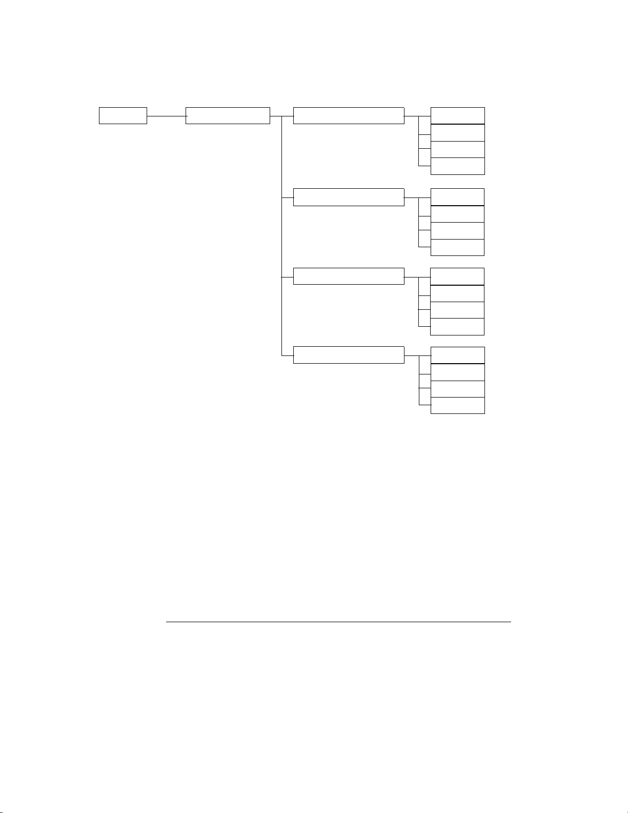
Figure 6-1
Measure and Other TDR Specific Menus
Blue Key TDR/TDT Measure TDR minimum reflection
TDR maximum reflection
TDT propagation delay
TDT gain
channel #
response #
Cancel
Enter
channel #
response #
Cancel
Enter
channel #
response #
Cancel
Enter
channel #
response #
Cancel
Enter
TDR Setup menu.
6-3
Page 98

Measure and Other TDR Specific Menus
TDR/TDT Measure Menu
TDR/TDT Measure Menu
To display the Measure menu, press the blue key immediately followed by the
TDR/TDT Measure key on the TDR plug-in module. There are four automated
measurements which may be selected: TDR minimum reflection, TDR maximum
reflection, TDT propagation delay, and TDT gain.
TDR Minimum Reflection
Pressing the TDR minimum reflection softkey display the automatically calculated
minimum percent reflection value at the bottom of the display under the
waveform graticule.
The TDR plug-in module must be calibrated and a reference plane established
before this measurement can be selected.
The calculation of the value is dependant on the type of response and stimulus
that are selected.
For differential response to differential stimulus and common mode response
to common mode stimulus, the following formula is used:
Minimum reflection 100
where:
V
= the minimum voltage value along the waveform
min
V
1ref50Ω
V
= the channel 1 reference plane voltage into a short
1ref0Ω
V
2ref50Ω
V
= the channel 2 reference plane voltage into a short
2ref0Ω
6-4
=
V
()
1
50
ref
V
------------- ------------- ------------- ---------- ------------- ------------- ------------- ------------ ---------
V
–
()
1
ref
V
1
0
Ω
ref
Ω
min
–
V
+
50
2
Ω
+
()
50
Ω
ref
V
2
ref
V
–
50
2
ref
0
Ω
Ω
= the channel 1 reference plane voltage into a 50 ohm load
= the channel 2 reference plane voltage into a 50 ohm load
Page 99

Measure and Other TDR Specific Menus
TDR/TDT Measure Menu
For differential response to common mode stimulus and common mode
response to differential stimulus, the following formula is used.
Minimum reflection 100
=
V
----------- ------------- ------------- ---------- ------------- -----------
------------ ------------- ------------- ---------- ------------- ------------- ------------- ------------ ----------
V
()
1
50
ref
------------- ------------- ------------- ---------- ------------- ------------- ------------- ------------ ---------
V
–
()
1
50
min
ref
2
V
–
Ω
+
1
0
Ω
ref
2
where:
V
= the minimum voltage value along the waveform
min
V
V
V
V
= the channel 1 reference plane voltage into a 50 ohm load
1ref50Ω
= the channel 1 reference plane voltage into a short
1ref0Ω
= the channel 2 reference plane voltage into a 50 ohm load
2ref50Ω
= the channel 2 reference plane voltage into a short
2ref0Ω
For all other stimulus, the following formula is used.
V
–
50
Minimum reflection 100
=
minVref
------------ ------------- ------------ ----
V
50
ref
Ω
V
–
0
Ω
ref
Ω
where:
V
= the minimum voltage value along the waveform
min
V
= the reference plane voltage into a 50 ohm load
ref50 Ω
V
= the reference plane voltage into a short
ref0Ω
Key Path blue key TDR/TDT Measure TDR minimum reflection
V
+
2
Ω
()
50
Ω
ref
V
2
ref
V
–
50
2
ref
0
Ω
Ω
6-5
Page 100

Measure and Other TDR Specific Menus
TDR/TDT Measure Menu
TDR Maximum Reflection
Pressing the TDR maximum reflection softkey display the automatically calculated
maximum percent reflection value at the bottom of the display under the
waveform graticule.
The TDR plug-in module must be calibrated and a reference plane established
before this measurement can be selected.
The calculated value is dependant on the type of response and stimulus that
are selected.
For differential response to differential stimulus and common mode response
to common mode stimulus, the following formula is used:
Maximum reflection 100
=
V
------------- ------------ ------------- ----------- ------------- ------------ ------------- ------------- ---------
V
()
1
50
ref
V
–
()
1
ref
V
1
0
Ω
ref
Ω
max
–
V
+
50
2
Ω
+
()
50
Ω
ref
V
2
ref
V
–
50
2
ref
0
Ω
Ω
where:
= the maximum voltage value along the waveform
V
max
V
V
V
V
= the channel 1 reference plane voltage into a 50 ohm load
1ref50Ω
= the channel 1 reference plane voltage into a short
1ref0Ω
= the channel 2 reference plane voltage into a 50 ohm load
2ref50Ω
= the channel 2 reference plane voltage into a short
2ref0Ω
For differential response to common mode stimulus and common mode
response to differential stimulus, the following formula is used.
Maximum reflection 100
=
V
------------- ------------ ------------- ----------- ------------ -----------
------------ ------------ ------------- ----------- ------------- ------------ ------------- ------------- ----------
V
()
1
50
ref
------------- ------------ ------------- ----------- ------------- ------------ ------------- ------------- ---------
V
–
()
1
max
ref
V
+
50
2
ref
50
Ω
Ω
2
V
–
1
Ω
ref
V
+
()
0
2
Ω
ref
V
–
50
2
ref
0
Ω
Ω
2
where:
V
= the maximum voltage value along the waveform
max
V
V
V
V
= the channel 1 reference plane voltage into a 50 ohm load
1ref50Ω
= the channel 1 reference plane voltage into a short
1ref0Ω
= the channel 2 reference plane voltage into a 50 ohm load
2ref50Ω
= the channel 2 reference plane voltage into a short
2ref0Ω
6-6
 Loading...