


HP 37717C
Communications
Performance Analyzer
User’s Guide
Dsn/Sonet
Operation

Copyright HewlettPackard Ltd.1998
All rights reserved.
Reproduction,
adaption, or
translation without
prior written
permission is
prohibited, except as
allowed under the
copyright laws.
HP Part No.
37717-90403
First edition, 03/98
Printed in U.K.
Warranty
The information
contained in this
document is subject to
change without notice.
Hewlett-Packard makes
no warranty of any
kind with regard to this
material, including,
but not limited to, the
implied warranties or
merchantability and
fitness for a particular
purpose.
Hewlett-Packard shall
not be liable for errors
contained herein or for
incidental or
consequential
damages in connection
with the furnishing,
performance, or use of
this material.
WARNING
Warning Symbols
Used on the Product
!
The product is marked
with this symbol when
the user should refer to
the instruction
manual in order to
protect the apparatus
against damage.
The product is
marked with this
symbol to indicate that
hazardous voltages are
present
The product is marked
with this symbol to
indicate that a laser is
fitted. The user should
refer to the laser safety
information in the
Calibration Manual.
Hewlett-Packard Limited
Telecommunications Networks Test Division
South Queensferry
West Lothian, Scotland EH30 9TG

User’s Guide:DSn/Sonet Operation
HP 37717C Communications
Performance Analyzer

About This Book
This book tells you how to select the features that you want to use for your test.
The selections available are presented in the following groups:
• Transmit and receive interfaces
• Test features, for example, the addition of errors and alarms to the test signal
• Measurements including test timing
• Storing, logging and printing results with general printer information
• Using instrument and disk storage
• Using the “Other” features.
The selections available will depend on the options fitted to your
instrument. The examples given in this book cover all options and
therefore may include selections which are not available on your
instrument.
NOTE If you intend using the instrument for SDH operation please
refer to User’s Guide (part number 37717-90402). The
contents are similar to this manual but with SDH
terminology used in place of SONET terminology.
iv

Contents
1 Setting the Interfaces
Setting PDH Transmit Interface 2
Setting PDH Transmit Binary Interface 4
Setting SONET Transmit Interface 6
Setting Jitter Transmit Interface 9
Setting Wander Transmit Interface 10
Selecting the Physical Transmit Interface for ATM Payloads 12
Setting SONET THRU Mode 14
Using Autosetup 16
Setting PDH Receive Interface 18
Setting PDH Receive Binary Interface 20
Setting SONET Receive Interface 21
Setting Jitter Receive Interface 23
Selecting the Physical Receive Interface for ATM payloads 25
2 Selecting Test Features
Using Transmit Overhead Setup 28
Using Receive Overhead Monitor 30
Setting Overhead Trace Messages 32
Generating Overhead Sequences 33
Using Receive Overhead Capture 35
Adding Frequency Offset to SONET Signal 37
Adding Frequency Offset to the PDH Signal 39
Setting up Signaling Bits 40
Setting Transmit Structured Payload/Test Signal (Options UKJ or
110) 43
Setting Receive Structured Payload/Test Signal 45
Connecting A Telephone Handset 47
v

Contents
Setting Transmit N X 64 kb/s
(N X 56 kb/s) Structured Payload/Test Signal 48
Setting Receive N X 64 kb/s (N X 56 kb/s) Structured Payload/Test
Signal 50
Inserting an External PDH Payload/Test Signal 52
Dropping an External Payload/Test Signal 54
Selecting ATM Cell Stream Payload 56
Selecting ATM Cell Stream Timing Distribution 57
Selecting ATM Cell Stream Headers and Interface 58
Adding Errors & Alarms at the SONET Interface 59
Adding Errors & Alarms to the PDH Interface/PDH Payload 60
Using FEAC Codes in the HP 37717C 62
Adding ATM Errors and Alarms 65
Setting PDH Spare Bits 66
Adding Pointer Adjustments 67
T1.105/GR-253 Pointer Sequences Explained 69
Using Pointer Graph Test Function 75
Stressing Optical Clock Recovery Circuits 77
Generating Automatic Protection Switch Messages 78
Inserting & Dropping Data Communications Channel 79
3 Making Measurements
Using Overhead BER Test Function 82
Test Timing 83
Making SONET Analysis Measurements 84
Making PDH Analysis Measurements 85
Measuring Jitter 87
Measuring Wander 89
Measuring Frequency 91
vi

Contents
Measuring Optical Power 92
Measuring Round Trip Delay 93
Monitoring Signaling Bits 95
Measuring Service Disruption Time 97
Performing an SONET Tributary Scan 99
Performing a SONET Alarm Scan 101
Performing a PDH Alarm Scan 103
Selecting the ATM Measurement Parameters 104
Making ATM Measurements 106
Measuring Cell Transfer Delay and Cell Delay Variation 107
Measuring ATM Non-Conforming cells and one-point Cell Delay
Variation. 109
Monitoring ATM Alarms 110
4 Storing, Logging and Printing
Saving Graphics Results to Instrument Store 112
Recalling Stored Graph Results 113
Viewing the Bar Graph Display 115
Viewing the Graphics Error and Alarm Summaries 117
Logging Graph Displays 119
Logging Results 120
Logging Results to Parallel (Centronics) Printer 123
Logging Results to HP-IB Printer 124
Logging Results to Internal Printer 125
Logging Results to RS-232-C Printer 126
Printing Results from Disk 127
Connecting an HP DeskJet Printer to a Parallel Port 128
Changing Internal Printer Paper 129
Cleaning Internal Printer Print Head 132
vii

Contents
5 Using Instrument and Disk Storage
Storing Configurations in Instrument Store 134
Storing Current Configurations on Disk 135
Setting up a Title for Configurations in Instrument Store 136
Recalling Configurations from Instrument Store 137
Formatting a Disk 138
Labeling a Disk 139
Managing Files and Directories on Disk 140
Adding Descriptors to Disk Files 144
Saving Graphics Results to Disk 145
Saving Data Logging to Disk 147
Recalling Configuration from Disk 148
Recalling Graphics Results from Disk 149
Copying Configuration from Instrument Store to Disk 150
Copying Configuration from Disk to Instrument Store 151
Copying Graphics Results from Instrument Store to Disk 152
Deleting a File on Disk 154
Deleting a Directory on Disk 155
Renaming a File on Disk 156
Creating a Directory on Disk 157
6 Selecting and Using "Other" Features
Coupling Transmit and Receive Settings 160
Suspending Test on Signal Loss 161
Setting Time & Date 162
Enabling Keyboard Lock 163
Enabling Beep on Received Error 164
Enabling Analysis Control 165
viii

Contents
Setting Error Threshold Indication 166
Dumping Display to Disk 167
Setting Screen Brightness and Color 169
Running Self Test 170
7 STS-1 SPE Background Patterns
8 ETSI/ANSI Terminology
ETSI/ANSI Conversion and Equivalent Terms 178
Index
ix

Contents
x

1
1 Setting the Interfaces
This chapter tells you how to set the
instrument interfaces to match the network
being tested.

Setting the Interfaces
Setting PDH Transmit Interface
Description PDH transmit interface settings should match network equipment
settings of Rate, Termination and Line Code and determine the Payload
to be tested.
TIP: To set the Transmitter and Receiver to the same interface settings
choose .
OTHER
SETTINGS CONTROL COUPLED
Option
Differences
If Option 110 is fitted the following SIGNAL rates and TERMINATION
choices apply:
2 Mb/s - Termination 75 Ω UNBAL or 120Ω BAL
34 Mb/s - fixed 75Ω UNBAL
DS1 - 100 Ω BAL; select LINE CODE from AMI or B8ZS, and OUTPUT
LEVEL from DSX-1 or DS1-LO.
DS3 - 75Ω UNBAL; LINE CODE fixed B3ZS; select OUTPUT LEVEL
from DS3-HI, DSX-3 or DS3-900’.
2

Setting the Interfaces
Setting PDH Transmit Interface
HOW TO: 1 Choose the required PDH SIGNAL rate.
If Option 110 is fitted, rates of 34Mb/s, 2Mb/s, DS1 and DS3 are
available. If Option UKJ is fitted rates of 2, 8, 34 and 140 Mb/s are
available.
2 If Option UH3, Binary Interfaces is fitted, choose the INTERFACE
required. See "Setting PDH Transmit Binary Interface " page 4.
3 Choose the required clock synchronization source (CLOCK SYNC).
If Option UH3, Binary Interfaces is fitted, the clock can be derived
from an external binary input.
If Option A3K, Jitter and Wander Generator, is fitted and 2 Mb/s
Signal rate is chosen the clock can be derived from an external 2 Mb/s
signal connected to the 2M REF IN port of the Jitter Generator
module.
4 If you have chosen 2 Mb/s as the PDH signal rate, choose the required
impedance (TERMINATION). At all other rates the impedance is
fixed. See Option Differences on previous page.
5 If you have chosen 2 Mb/s, DS1 or 8 Mb/s as the PDH signal rate,
choose the required coding (Line Code). At 34 Mb/s and 140 Mb/s
coding is fixed.
See Option Differences.
6 If required choose the FREQUENCY OFFSET value.
See “Adding Frequency Offset to SONET Signal” page 37
7 Choose the required Payload Type.
If Structured is chosen the PDH test signal must be set up. See
“Setting Transmit Structured Payload/Test Signal (Options UKJ or
110)” page 43.
If you have chosen 2 Mb/s as the PDH signal rate, the Framed choice
is expanded to provide a menu of 2 Mb/s framing types.
8 Choose the PATTERN type and PRBS POLARITY.
3

Setting the Interfaces
Setting PDH Transmit Binary Interface
Setting PDH Transmit Binary Interface
Description Option UH3, Binary Interfaces, provides binary NRZ interface for PDH
measurements. The interfaces can operate at any of the standard rates
±100 ppm.
PDH transmit binary interface settings should match the network
equipment thresholds and polarity requirements for the binary
interfaces
Variable Rate Binary Interface
If your instrument also includes Option UKK, variable rate binary
interface is available. This allows you to select fixed rates that are
different from standard telecom rates, and also to vary frequency over a
wide range. Applications include component test, testing satellite and
cable networks and testing PDH digital radios. A Product Note is
available (part number 5965-4885E) which explains the use of a variable
rate binary interface in the testing of PDH digital radios.
.
4

Setting the Interfaces
Setting PDH Transmit Binary Interface
HOW TO: 1 Set up the PDH transmit Interface as required. See "Setting PDH
Transmit Interface " page 2.
If INTERFACE [BINARY] is chosen on the
PDH MAIN SETTINGS
display, threshold and polarity choices are available for Data and
Clock.
If INTERFACE [CODED] is chosen on the
PDH MAIN SETTINGS
display, threshold and polarity choices are available for Clock only.
2 Choose the required thresholds.
EXT CLOCK polarity and threshold choices are only available if
CLOCK SYNC [EXT BIN] is chosen on the
PDH MAIN SETTINGS
display.
5

Setting the Interfaces
Setting SONET Transmit Interface
Setting SONET Transmit Interface
Description SONET transmit interface settings should match the network
equipment settings of Rate, Wavelength and Mapping, determine the
payload to be tested and set background conditions to prevent alarms
while testing.
TIP: If you wish to set the HP 37717C transmitter and receiver to the same
interface settings choose .
OTHER
SETTINGS CONTROL COUPLED
HOW TO: 1 Make your choice of SIGNAL rate.
If an optical rate is chosen, choose the required wavelength [1550] or
[1310].
If a BINARY rate is chosen, choose the required clock and data
polarity.
If STS-1 is chosen, choose the required interface level.
Choose INTERNAL unless THRU MODE is required.
2 Make your choice of CLOCK synchronization source. The RECEIVE
clock sync choice depends on the SONET Receive Interface choice.
3 If required choose the CLOCK (FREQUENCY) OFFSET value.
4 Choose FOREGROUND , BACKGROUND
6
F/G MAPPING

Setting the Interfaces
Setting SONET Transmit Interface
B/G MAPPING
MAPPING and type of payload. DS1 and DS3 are valid
payload type choices if Option UKJ, Structured PDH or Option 110
DSn SPDH, is fitted.
Mapping may be selected from a pictorial display by moving the cursor to
MAPPING and pressing .
OC-n/STS-n
x3/12
OC-1/STS-1
x1
SET
SONET ROCKET DIAGRAM
STS-12c SPE
x1
x1/4
STS-3c SPE
STS-1 SPE
x7
VTg
Bulk Filled
Bulk Filled
E4 Async
E3 Async
DS3
Bulk Filled
x1
VT6
x3
VT2
x4
VT1.5
Bulk Filled
E1 Async
E1 Float
Bulk Filled
DS1 Async
Use and to move between STS Layer Selection, VT Layer
Selection and Payload Layer Selection. Use and to set the
mapping and to set your selection.
SET
5 If VT-6 mapping is chosen, VT CONCATENATION selection is
enabled, choose OFF or the tributary at which the concatenation
begins, VT6-2C through VT6-6C.
The BACKGROUND, PATTERN IN OTHER VT2’s is fixed at
NUMBERED, that is, each VT-6 contains a unique number to allow
identification in case of routing problems.
6 If VT-2, or VT1.5 mapping is chosen, choose the test tributary
CHANNEL. Including the STS-3 for an STS-12 signal.
7 Choose the payload framing under PAYLOAD TYPE or VT PA YLOAD .
STRUCTURED and INSERT are available if Option UKJ , Structured
PDH or Option 110 DSn SPDH is fitted.
7

Setting the Interfaces
Setting SONET Transmit Interface
If STRUCTURED is chosen, the Payload test signal must be set-up.
See “Setting Transmit Structured Payload/Test Signal (Options UKJ
or 110)” page 43.
If INSERT is chosen, see “Inserting an External PDH Payload/Test
Signal” page 52.
8 Choose the PATTERN type and PRBS polarity.
NOTE If interfacing at STS-1 with a user word pattern chosen then a false frame
synchronization may occur. This is due to the effect of the standard ITU-T G.707
scrambling used at STS-1 when applied to a fixed payload.
The scrambler may produce a false (F628) frame synchronization from the fixed
payload. At STS-1 only a single F628 pattern is available for frame synchronization.
If the false pattern is detected by the receiver this will result in frame synchronization
being indicated but multiple alarms will occur . If this condition is suspected, change
the PATTERN choice to PRBS and check that the multiple alarms are cleared when
proper frame synchronization is achieved.
9 If required, choose 2M/DS3/34M/140M OFFSET value.
10 If 2 Mb/s framing PCM30 or PCM30CRC is chosen, set the CAS ABCD
bit value.
11 Choose the mapping required in the background (non-test) SPE’s.
Refer to Appendix A "STS-1 SPE Background P atterns " page 176 for
a table of background patterns for STS-1 SPE.
12 If VT-2 mapping is chosen for the test SPE, choose the PATTERN IN
OTHER VT-2s.
8

Setting the Interfaces
Setting Jitter Transmit Interface
Setting Jitter Transmit Interface
Description: You can add jitter to the transmitted PDH or SONET signal at all ANSI
rates. You can source the jitter modulation internally or from an external
source.
HOW TO: 1 If you are adding jitter to the PDH signal, set up the PDH transmit
interface. See "Setting PDH Transmit Interface " page 2.
If you are adding jitter to the SONET signal, set up the SONET
transmit interface. See "Setting SONET Transmit Interface " page 6.
2 Choose JITTER/WANDER [JITTER].
If you wish to add wander to the PDH or SONET signal, see "Setting
Wander Transmit Interface " page 10.
3 Choose JITTER [ON].
4 Choose the modulation source.
If EXTERNAL is chosen, connect the external source to the MOD IN
port of the JITTER TX module. Up to 10 UI of external jitter
modulation can be added at the MOD IN port.
5 Choose the jitter range, jitter modulating frequency and jitter
amplitude.
9

Setting the Interfaces
Setting Wander Transmit Interface
Setting Wander Transmit Interface
Description: You can add Wander to the 2 Mb/s PDH signal and the STS-3 and
STS-12 SONET signal. An external 2 Mb/s clock must be connected to
the 2M REF IN port of the Jitter TX module.
HOW TO: 1 Connect an external 2 Mb/s clock to the 2M REF port of the Jitter TX
module.
2 If you are adding jitter to the 2 Mb/s PDH signal set up the PDH
transmit interface and choose CLOCK SOURCE [EXT JITTER]. See
"Setting PDH Transmit Interface " page 2.
If you are adding jitter to the STS-3 or STS-12 SONET signal set up
the SONET transmit interface and choose an external CLOCK
SOURCE. See "Setting SONET Transmit Interface " page 6.
3 Choose JITTER/WANDER [WANDER].
If you wish to add jitter to the PDH or SONET signal, see "Setting
Jitter Transmit Interface " page 9.
4 Choose WANDER [ON].
10

Setting the Interfaces
Setting Wander Transmit Interface
5 Choose the modulation source.
If EXTERNAL is chosen, connect the external source to the MOD IN
port of the JITTER TX module.
Up to 10 UI of external wander modulation can be added at the MOD
IN port.
6 Choose the wander range, modulating frequency and amplitude.
11

Setting the Interfaces
Selecting the Physical Transmit Interface for ATM Payloads
Selecting the Physical Transmit Interface for
ATM Payloads
Description ATM transmit physical layer settings should match the network
equipment settings in the same way as the SDH and PDH transmit
interfaces. The Interface selections available are determined by the
PDH/DSn and SDH modules fitted to your instrument.
Your selections are automatically transferred to the other TRANSMIT
displays. Selection of STM-4 OPTICAL signal at the ATM PHYSICAL
LAYER will cause the transmitter output SDH to change to STM-4
OPTICAL.
TIP: If you wish to set the HP 37717C transmitter and receiver to the same
interface settings choose .
OTHER
SETTINGS CONTROL COUPLED
HOW TO: 1 Make your choice of SIGNAL rate.
If an optical rate is chosen, choose the required wavelength.
Choose INTERNAL unless THRU MODE is required. Jitter may be
introduced into an STM-1, 140Mb/s, 32Mb/s or 2Mb/s signal with ATM
payload if THRU MODE is chosen.
2 Make your choice of CLOCK synchronization source. At SDH rates,
the RECEIVE clock sync choice is dependent upon the SDH Receive
12

Setting the Interfaces
Selecting the Physical Transmit Interface for ATM Payloads
Interface choice.
3 If the 2Mb/s rate is selected, select CRC-4 MULTIFRAME or
.
OFF
ON
4 If the 140Mb/s or 34Mb/s rate is selected, select the TRAIL TRACE
message type:
For the standard trail trace message”HP37717C” set TRAIL TRACE
to .
TEST
For a unique 15 character message, set TRAIL TRACE to
TIP: If is selected, use for a pop-up menu to select the message
USER
SET
USER
characters.
13

Setting the Interfaces
Setting SONET THRU Mode
Setting SONET THRU Mode
Description THRU mode is used to non-intrusively monitor SONET lines where no
protected monitor points are available.
STS-1, STS-3
You can substitute a new payload, Transport Overhead (TOH) and Path
Overhead (POH) in the received STS-1/3 signal for testing.
14

Setting the Interfaces
Setting SONET THRU Mode
STS-12
With Option 130 or 131, the overhead and payload may be overwritten
for STS-3C. TOH overwrite is available for STS-12C.
The Transmitter and receiver settings are automatically coupled in
THRU MODE. To select STS-3C or STS-12C select and setup
RECEIVE
the receiver mapping as required.
HOW TO:
1 Make the PAYLOAD OVERWRITE choice required.
If STS-1, VT-6, VT-2 or VT1.5 is chosen, the B1, B2 and B3 BIPs are
recalculated before transmission and the Mapping, Selected VT, VT Payload,
Pattern, Tributary Offset and Pattern in other VT’s settings are displayed. To
choose the settings in these, see "Setting SONET Transmit Interface " page 6,
steps 4 through 10.
2 Make the TOH+POH OVERWRITE choice required.
Y ou can only modify those overhead bytes available under
SONET TEST FUNCTION SONET
: Errors & Alarms, Sequences,
TRANSMIT
Overhead BER, APS Messages, DCC Insert and Stress Test.
The B1, B2 and B3 BIPs are recalculated before transmission.
15

Setting the Interfaces
Using Autosetup
Using Autosetup
Description The Autosetup function allows you to speed up the configuration of the
instrument when making PDH, SDH or SONET measurements.
Autosetup will search the interface chosen on the display
and attempt to configure the instrument to match the received signal.
Autosetup will detect ATM or any of the PRBS patterns the transmitter
can generate. ATM is considered to be a payload of PDH or SDH.
Both MONITOR and TERMINATE modes are tried in the search for a
received signal.
HOW TO: 1 Connect the HP 37717C to the network and select the required
RECEIVE
2 Press .
The display will show an Autosetup HELP page.
interface on the HP 37717C.
AUTO SETUP
OTHER
RECEIVE
PDH Input
In PDH there are three framing possibilities for 140 Mb/s, 34 Mb/s, 8 Mb/
s and 2 Mb/s, (34Mb/s, DS3, 2M and DS1 for Option 110) namely
Unframed Framed and Structured.
16

Setting the Interfaces
Using Autosetup
NOTE Structured is not covered by Autosetup because searching through a
PDH framing structure would take an unacceptable amount of time.
All line rates are searched for a signal. If a signal is found, a search for
framing pattern is made. All possible framing structures are searched
except for Structured.
If a framing pattern is found, a search for PRBS pattern is made.
SONET Input
If an STS-12 interface is chosen, the search will start on the STS-3
selected for test. All SONET line rates are searched for an electrical,
optical or binary signal.
If a signal is found, a search of payloads will start.
The payload search starts with STS-12c SPE in STS-12 and continues
with ATM, STS-1 SPE, VT-6, STS-3C, VT-2 and VT1.5.
For each pa yload a search is made to find a framing pattern. If a framing
pattern is found, a search for PRBS patterns is made.
TIP: If it is known that the signal of interest is in a particular STS-3 e.g.
number 3, then the Autosetup search can be speeded up by setting the
RECEIVE
for a signal will then start in STS-3 number 3.
display MAPPING [FOREGROUND] to STS-3 [3]. The search
17

Setting the Interfaces
Setting PDH Receive Interface
Setting PDH Receive Interface
Description PDH Receive interface settings should match the network equipment
settings of Rate, Termination and Line Code and determine the Payload
to be tested.
TIP: If you wish to set the HP 37717C transmitter and receiver to the same
interface settings choose .
OTHER
SETTINGS CONTROL COUPLED
HOW TO: 1 Choose the required SIGNAL source.
2 If Binary Interfaces, Option UH3, is fitted, choose the INTERFACE
required. See "Setting PDH Receive Binary Interface " page 20.
3 If you have chosen 2 Mb/s as the PDH signal rate, choose the required
impedance (TERMINATION). At all other rates the impedance is
fixed.
4 If you have chosen 2 Mb/s, 8 Mb/s or DS1 (Option 110) as the PDH
signal rate, choose the required LINE CODE. At 140 Mb/s, 34 Mb/s
and DS3 coding is fixed.
5 If you are measuring at the network equipment monitor point set the
LEVEL field to MONITOR.
18

Setting the Interfaces
Setting PDH Receive Interface
6 The received signal will be 20 to 26 dB below the normal level. To
return the received signal to normal, choose the required GAIN level.
The received signal may also require EQUALIZATION to compensate
for cable losses.
7 Choose the required Payload Type.
If Structured is chosen, the PDH test signal must be set up. See
“Setting Transmit Structured Payload/Test Signal (Options UKJ or
110)” page 43.
If you choose 2 Mb/s as the PDH signal rate, the Framed choice is
expanded to provide a menu of 2 Mb/s framing types.
8 Choose the required PATTERN.
9 Choose the required PRBS POLARITY.
If your PRBS Polarity choice matches ITU-T Recommendation O .150,
ITU is displayed alongside your choice.
19

Setting the Interfaces
Setting PDH Receive Binary Interface
Setting PDH Receive Binary Interface
Description PDH Receive binary interface settings should match the network
equipment threshold and polarity requirements for the binary interfaces.
HOW TO: 1 Set up the PDH receive interface required. See "Setting PDH Receive
Interface " page 18.
If INTERFACE [CODED] is chosen, binary interfaces are not
available.
2 If INTERFACE [BINARY] is chosen, then choose the required
THRESHOLDS and POLARITY for Clock and Data.
20

Setting the Interfaces
Setting SONET Receive Interface
Setting SONET Receive Interface
Description SONET Receive interface settings should match the network equipment
settings of Rate and Mapping, and determine the payload to be tested.
TIP: If you wish to set the HP 37717C transmitter and receiver to the same
interface settings, choose .
OTHER
SETTINGS CONTROL COUPLED
HOW TO: 1 Choose the required SIGNAL source.
If a BINARY rate is chosen, choose the required clock and data
polarity.
Choose mapping and type of payload.
Note: If Option UKJ is fitted then DS1 and DS3 payloads are
unstructured. Option 110 offers fully structured DS1 and DS3
payloads.
2 If VT -6 mapping is chosen, and CONC ATENATION is enabled, choose
the tributary at which the concatenation begins, VT6-2C through VT66C.
If VT-6, VT-2 or VT-1.5 mapping is chosen, choose the test tributary
under CHANNEL.
3 Choose the payload framing under PAYLOAD TYPE or VT PA YLOAD .
STRUCTURED and DROP are only available if Option UKJ,
21

Setting the Interfaces
Setting SONET Receive Interface
Structured PDH or Option 110 DSn SPDH is fitted.
If STRUCTURED is chosen the Payload test signal must be set up . See
“Setting Receive Structured Payload/Test Signal” page 45.
If DROP is chosen, see “Dropping an External Payload/Test Signal”
page 54.
4 Choose the PATTERN type and PRBS polarity.
NOTE If interfacing at STS-1 with a user word pattern chosen, then a false
frame synchronization may occur. This is due to the effect of the standard
ITU-T G.707 scrambling used at STS-1 when applied to a fixed payload.
The scrambler may produce a false (F628) frame synchronization from the
fixed payload. At STS-1 only a single F628 pattern is available for frame
synchronization.
If the false pattern is detected by the receiver this will result in frame
synchronization being indicated but multiple alarms will occur. If this
condition is suspected, change the PATTERN choice to PRBS and check
that the multiple alarms are cleared when proper frame synchronization
is achieved.
22

Setting the Interfaces
Setting Jitter Receive Interface
Setting Jitter Receive Interface
Description: PDH Jitter and PDH error measurements are made simultaneously
when a PDH jitter measurement Option is fitted. The measurements are
made on the normal input to the PDH receiver and the interface
selections are the normal PDH Receiver selections. The jitter receive
interface is selected with JITTER.
SDH/SONET Jitter and SDH/SONET error measurements are isolated
individual measurements. The SDH/SONET jitter measurement is made
on an SDH/SONET input to the Jitter module and there is a specific
receive interface displayed with .
The choices made on the jitter receive interface determine the jitter
measurement range, the threshold level for determining a jitter hit and
which filters are used in the jitter measurement.
RECEIVE
PDH
RECEIVE
SDH /SONET JIT
HOW TO: 1 Choose the RECEIVER RANGE - the jitter measurement range.
2 Choose the HIT THRESHOLD level - if the received jitter exceeds the
value chosen a jitter hit is recorded.
3 Choose the FIL TER you wish to inc lude in the peak to peak and RMS
jitter measurement.
23

Setting the Interfaces
Setting Jitter Receive Interface
4 If Option A3L, A3V or A3N, Jitter Receiver, is fitted, an ADDITIONAL
RMS FILTER choice is provided. You may possibly require different
filters to be connected for peak to peak and RMS measurements. The
additional RMS filter choice allows you the choice of a 12 kHz (high
pass) HP filter for RMS measurement only. If 12 kHz HP is chosen
under FILTER, the additional RMS filter choice is not available.
24

Setting the Interfaces
Selecting the Physical Receive Interface for ATM payloads
Selecting the Physical Receive Interface for
ATM payloads
Description ATM receive physical layer settings should match the network
equipment settings in the same way as the SDH and PDH receive
interfaces. The Interface selections available are determined by the
PDH/DSn and SDH modules fitted to your instrument.
Your selections are automatically transferred to the other RECEIVE
displays. For example selection of STM-4 OPTICAL signal at the ATM
PHYSICAL LAYER will cause the receiver output SDH to change to
STM-4 OPTICAL.
TIP: If you wish to set the HP 37717C transmitter and receiver to the same
interface settings choose .
OTHER
SETTINGS CONTROL COUPLED
HOW TO: 1 Choose the required SIGNAL source.
2 For a 2Mb/s rate, select the TERMINATION and LINE CODE.
3 For a 2, 34 or 140Mb/s rate, select the TERMINATION.
4 For a 2Mb/s rate, select the CRC-4 MULTIFRAME.
5 For an STM-4 rate select the STM-1 UNDER TEST.
25

Setting the Interfaces
Selecting the Physical Receive Interface for ATM payloads
26

2
2 Selecting Test Features

Selecting Test Features
Using Transmit Overhead Setup
Description You can set an overhead byte to a known static state to aid in
troubleshooting, for example, to quickly check for "stuck bits" in path
overhead bytes. Transport Overhead, Path Overhead and Trace
Messages can be set using this feature.
HOW TO: 1 Set up the SONET transmit interface and payload required.
2 Choose the type of overhead to SETUP.
If STS-12 is chosen as the SONET interface, choose the STS-3#, STS1# TOH you wish to set up. If STS-3 is chosen as the interface select
the STS-1# TOH.
If TRACE MESSAGES is chosen, see "Setting Overhead Trace
Messages " page 32.
DEFAULT - Use to set all overhead bytes to the standard values
defined by ITU-T. If a test function is active then the overhead byte
value is determined by the choices made in the Test Function. For
example if APS Messages is chosen, the K1K2 value is determined by
28

Selecting Test Features
Using Transmit Overhead Setup
the APS Messages setup.
3 If TOH (Transport Overhead) is chosen, choose the format to be
displayed from the STS-1# field.
If STS-1#1,2,3 is chosen, the hexadecimal value of all 81 bytes of the
STS-1 transport overhead selected are displayed
The values of the bytes can be set using
INCREASE DIGIT
If BYTE NAMES is chosen, the labels for the STS-1#1,2,3 overhead
bytes are displayed.
4 If POH (Path Overhead) is chosen, choose the TYPE of overhead
within the STS-1 under test to be setup.
J1 and J2 bytes can be set under Path Overhead or Trace Messages.
H4 byte has a choice of sequences for VT-6, VT-2 and VT-1.5
(OptionOption 110) mapping:
Full Sequence - 48 byte binary sequence.
Reduced Sequence - Binary count sequence of 0 to 3 i.e. 111111(00
to 11).
COC1 Sequence - Binary count sequence of 0 to 3 i.e. 110000(00 to
11).
H4 byte is transmitted as all zeros for 34Mb/s and DS3 (Option 110).
.
DECREASE DIGIT
NOTE Any bit of an overhead byte which is displayed as x or s cannot be set at
any time. All other bits can be set to 0 or 1.
TIP: You can set all overhead bytes to the default state by selecting SETUP
DEFAULT
You can set all overhead bytes and test functions to the default state by
recalling Stored Settings [0] on the display.
.
OTHER
29

Selecting Test Features
Using Receive Overhead Monitor
Using Receive Overhead Monitor
Description When first connecting to a SONET network, a start up confidence check
can be made by viewing the behavior of all the overhead bytes. If the
SONET network shows alarm indications, some diagnosis of the problem
may be gained from viewing all the overhead bytes.The OVERHEAD
MONITOR display is updated once per second (once per 8000 frames)
approximately.
HOW TO: 1 Set up the receive SONET interface and payload as required.
2 Choose the type of overhead to MONITOR.
If TRACE MESSAGES is chosen, you can monitor a data message to
verify portions of the network.
If the 16 byte CRC7 message structure is detected, the 15 characters
within the message are displayed.
If the CRC7 structure is not detected in J1, the 64 byte message
format is assumed and displayed. If the CRC7 structure is not detected
for J0 or J2, all 16 bytes are displayed.
3 If TOH (Transport Overhead) is chosen, choose the format to be
displayed from the STS-1# field.
Bytes shown unlabeled have not yet been defined.
30

Selecting Test Features
Using Receive Overhead Monitor
If STS-1#1,2,3 is chosen, the hexadecimal value of all 81 bytes of
transport overhead is displayed and can be set using
DECREASE DIGIT INCREASE DIGIT
.
If BYTE NAMES is chosen, the labels for the STS-1#1,2,3 overhead
bytes is displayed.
4 If POH (Path Overhead) is chosen, choose the source of the overhead
SPE or VTSPE.
J1 and J2 bytes can be monitored under Path Overhead or Trace
Messages
5 If APS MESSAGES is chosen, choose the TOPOLOGY,
(G.253) or (G.1230). The K1 and K2 bits are monitored.
RING
LINEAR
6 If LABELS is chosen, the S1 sync status and STS path label (C2) are
monitored.
TIP: If any abnormal behavior is observed on a particular path or section
overhead byte, or an associated group of bytes (3xA1,3xA2; D1 - D3), the
RECEIVE
TEST FUNCTION
display of can be
OVERHEAD CAPTURE
used to "Zoom" in on the suspect byte or bytes on a frame by frame basis.
See "Using Receive Overhead Capture " page 35.
31

Selecting Test Features
Setting Overhead Trace Messages
Setting Overhead Trace Messages
Description You can insert a data message to verify portions of the network:
J0 verifies the section overhead.
J1 verifies the STS-1 SPE or STS-3c SPE path connection.
J2 verifies the VT- SPE path connection.
32

Selecting Test Features
Generating Overhead Sequences
Generating Overhead Sequences
Description You may insert a pattern into a functional group of overhead bytes for
testing or troubleshooting purposes.
HOW TO: 1 Set up the SONET transmit interface and payload required.
2 Choose the type of sequence required.
SINGLE RUN - runs the sequence once and then stops.
REPEAT RUN - runs the sequence repeatedly until STOPPED is
chosen.
3 Choose the overhead type as required.
SOH- Section Overhead
LOH- Line Overhead
POH - Path Overhead
4 Choose the byte or bytes of overhead required.
5 Set up the required number of data patterns and the number of
frames in which each data pattern should appear.
Y our sequence is derived from up to 5 blocks of hexadecimal data. Each
block can be transmitted in up to 64,000 frames.
The data and the number of frames are set using
DECREASE DIGIT
33

Selecting Test Features
Generating Overhead Sequences
INCREASE DIGIT
6 Start the sequence by choosing [STARTED].
.
34

Selecting Test Features
Using Receive Overhead Capture
Using Receive Overhead Capture
Description Section, Line and Path overhead provide network support functions,
responding dynamically to network conditions and needs. It is therefore
useful to capture overhead activity on a frame by frame basis.
HOW TO: 1 Set up the receive SONET interface and payload as required.
2 Choose the overhead type as required.
SOH- Section Overhead
LOH- Line Overhead
POH- Path Overhead
3 Choose the Byte or bytes of overhead to be captured.
Choose the TRIGGER to determine the start point of the capture. -
starts immediately the capture is initiated. Can be used to provide a
frame by frame monitor of the chosen byte or bytes.
-captures activity after your specified overhead state has occurred.
ON
Can be used for transient detection from a specified expected state.
ON NOT
your specified overhead state. Can be used for transient detection from a
specified expected state.
4 Up to 16 records of overhead state are provided. Each record will
represent between 1 and 64,000 frames. A capture is started by
- captures activity after the first occurrence of a deviation from
OFF
35

Selecting Test Features
Using Receive Overhead Capture
pressing CAPTURE and terminates when up to 16 records
ST ARTED
have been captured. The capture can be terminated earlier by pressing
CAPTURE .
STOPPED
36

Selecting Test Features
Adding Frequency Offset to SONET Signal
Adding Frequency Offset to SONET
Signal
Description Frequency offset can be added to the SONET interface rate signal and to
the payload signal.
HOW TO: SONET Line Rate Offset
Choose the amount of frequency offset required.
You can set the Frequency Offset in the range -999 ppm to +999 ppm in 1
ppm steps using and .
The amount of applied Frequency Offset can be varied while
measurements are taking place.
If the value of the SONET line rate offset chosen is sufficient to cause the
maximum stuff rate to be exceeded, the asynchronous payload is offset to
prevent bit errors occurring and the maximum stuff rate is maintained.
When Floating Byte 2 Mb/s is chosen, in conjunction with SONET line
rate offset, the chosen tributary will be offset as the line rate is offset.
(No pointer movements).
DECREASE DIGIT INCREASE DIGIT
37

Selecting Test Features
Adding Frequency Offset to SONET Signal
Tributary Offset ±100 ppm
Choose the amount of tributary offset required.
You can set the Offset in the range -100 ppm to +100 ppm in 1 ppm steps
using and .
DECREASE DIGIT INCREASE DIGIT
The amount of applied Frequency Offset can be varied while
measurements are taking place.
Tributary offset affects the stuff rate but does not cause pointer
movements and can be used to test mapping jitter. If the combined value
of SONET line rate offset and tributary offset chosen is sufficient to
cause the maximum stuff rate to be exceeded the payload is offset to
prevent bit errors occurring and the maximum stuff rate is maintained.
38

Selecting Test Features
Adding Frequency Offset to the PDH Signal
Adding Frequency Offset to the PDH
Signal
Description You can add Frequency Offset to the interface PDH signal at all rates.
Frequency Offset can be added at preset ITU values or as User defined
values in the range ±100 ppm.
The preset value changes according to the PDH signal rate chosen.:
2 Mb/s - ±50 ppm
8 Mb/s - ±30 ppm
34 Mb/s - ±20 ppm
140 Mb/s - ±15 ppm
For Option 110 instruments 34 Mb/s , 2Mb/s and DS1 32 ppm and DS3 20
ppm are available.
HOW TO: Choose the amount of frequency offset required.
If USER OFFSET is chosen you can set the Frequency Offset in the
range -100 ppm to +100 ppm in 1 ppm steps using
INCREASE DIGIT
The amount of applied Frequency Offset can be varied while
measurements are taking place.
and .
DECREASE DIGIT
39

Selecting Test Features
Setting up Signaling Bits
Setting up Signaling Bits
Description The HP 37717C receiver can be used to monitor the state of signaling
bits in received 2 Mb/s signals with timeslot-16 CAS (PCM30 or
PCM30CRC) multiframing, structured or unstructured, and also in DS1
framed and structured signals (Option 110 instruments).
The HP 37717C transmitter can be configured to generate these signals
and the state of the signaling bits defined by the user, as follows:
2.048 Mb/s Signal When transmitting 2.048 Mb/s signals with timeslot-16 CAS (PCM30 or
PCM30CRC) multiframing the state of A,B,C ,D signaling bits can be set.
The signaling bits of all timeslots are set to the user-defined 4 bit value.
DS1 Signal
(Option 110)
HOW TO Transmit a 2 Mb/s signal with user-defined signaling
When transmitting a DS1 framed, structured signal the values of the
A,B signaling bits for D4 and SLC-96 payloads, and A,B,C,D signaling
bits for ESF payloads can be defined. signaling is not offered for a
64 kb/s or Nx64 kb/s Test Signal.
bits
PDH Operation
When transmitting a 2.048 Mb/s signal, (or a 2.048 Mb/s signal as part of
a higher rate structured signal, i.e. 140 Mb/s, 34 Mb/s or 8 Mb/s) the
A,B,C,D signaling bits can be set.
1 On the HP 37717C press and select a PDH interface.
2 On the MAIN SETTINGS page select a 2 Mb/s SIGNAL and set the
PAYLOAD TYPE to PCM30 or PCM30CRC (structured or
unstructured).
3 Set the 2M CAS ABCD bits as required. If you select an unstructured
payload the signaling bits are set up on the MAIN SETTINGS page; if
structured is selected they are set up on the STRUCT’D SETTINGS
page.
TRANSMIT
4 Press and set up the HP 37717C receiver interface to match
the signal being output from the HP 37717C transmitter.
40
RECEIVE

Selecting Test Features
Setting up Signaling Bits
SONET Operation
1 On the HP 37717C press and select an SONET interface.
TRANSMIT
2 On the MAIN SETTINGS page set MAPPING to ASYNC 2 Mb/s or FL
BYTE 2 Mb/s and set the VT PAYLOAD to PCM30 or PCM30CRC
(structured or unstructured).
3 Set the CAS ABCD bits as required. If you select an unstructured
payload the signaling bits are set up on the MAIN SETTINGS page; if
structured is selected they are set up on the STRUCT’D PAYLOAD
page.
4 Press and setup the HP 37717C receiver interface to match
RECEIVE
the signal being output from the HP 37717C transmitter.
HOW TO Transmit a DS1 signal with user-defined signaling bits
(Option 110 instruments)
PDH Operation
When transmitting a DS1 framed, structured signal or a DS3 signal
structured down to DS1, the values of A,B signaling bits for D4 and SLC96 payloads, and the A,B,C,D signaling bits for ESF payloads can be set.
1 On the HP 37717C press and select a PDH interface.
2 On the MAIN SETTINGS page select a DS1 SIGNAL and set the
PAYLOAD TYPE to D4, ESF or SLC-96 and STRUCTURED.
3 On the STRUCT’D SETTINGS page set the TEST SIGNAL to 56 kb/s
or Nx56 kb/s
4 Set the A,B bits (for D4 and SLC-96) and A,B,C,D bits (for ESF) as
required. Press and set up the HP 37717C receiver
RECEIVE
interface to match the signal being output from the HP 37717C
transmitter.
SONET Operation
1 On the HP 37717C press and select an SONET interface.
TRANSMIT
TRANSMIT
2 On the MAIN SETTINGS page set MAPPING to ASYNC DS1 and set
the VT PAYLOAD to D4, ESF or SLC-96 and STRUCTURED.
41

Selecting Test Features
Setting up Signaling Bits
3 On the STRUCT’D PAYLOAD page set the TEST SIGNAL to 56 kb/s
or Nx56 kb/s
4 Set the A,B bits (for D4 and SLC-96) and A,B,C,D bits (for ESF) as
required. Press and set up the HP 37717C receiver
RECEIVE
interface to match the signal being output from the HP 37717C
transmitter.
42

Selecting Test Features
Setting Transmit Structured Payload/Test Signal (Options UKJ or 110)
Setting Transmit Structured Payload/
Test Signal (Options UKJ or 110)
Description Structured PDH Payload/Test Signal settings determine the SONET
payload or the PDH test signal to be tested and set any background (non
test) conditions to prevent alarms while testing. Fully structured DS1 or
DS3 payloads are only available if Option 110 is fitted.
TIP: If you wish to set the HP 37717C transmitter and receiver to the same
Payload settings, choose .
OTHER
SETTINGS CONTROL
OUPLED
HOW TO: 1 Choose the required Test Signal rate. If N X 64 kb/s (or N x 56 kb/s
Option 110) is chosen, see "Setting Transmit N X 64 kb/s (N X 56 kb/
s) Structured Payload/Test Signal " page 48.
2 Choose the Framing pattern of the PAYLOAD.
If 2 Mb/s (or DS1 Option 110 instruments) TEST SIGNAL is chosen,
INSERT 2 Mb/s (or INSERT DS1) is added to the menu. See
"Inserting an External PDH Payload/Test Signal " page 52
3 Choose the test tributary within the structured payload under 34Mb,
8Mb, 2Mb, 64 kb ( (DS2, DS1, 56kb/s for Option 110 instruments).
43

Selecting Test Features
Setting Transmit Structured Payload/Test Signal (Options UKJ or 110)
4 If 64 kb/s TEST SIGNAL is chosen, HANDSET is available (this is
only available for Option UKJ;, and is not present in Option 110
instruments). See "Connecting A Telephone Handset " page 47.
5 Choose the PATTERN type and PRBS polarity.
If your choice matches ITU-T Recommendation O.150, ITU is
displayed alongside your choice.
6 Choose the mapping required in the background (non-test) tributaries.
If 64 kb/s or N X 64 kb/s (or 56 kb/s or Nx 56 kb/s for Option 110
instruments) TEST SIGNAL is chosen, the B/G PA TTERN in the non
test timeslots is fixed as NUMBERED, that is, eac h timeslot contains
a unique number to allow identification in case of routing problems.
Signaling
7 If a 2 Mb/s PAYLOAD is transmitted with timeslot-16 CAS
multiframing (PCM30 or PCM30CRC selected), set the CAS ABCD bit
value. If a DS1 P AYLOAD is transmitted, signaling is only offered with
56 kb/s or nx56 kb/s Test Signals.
Select the values of AB signaling for SF and SLC-96 formats and
ABCD signaling for ESF. In SLC-96 mode choices are 0,1 or
alternating. In D4 mode AB choices are 0,1. See "Setting up Signaling
Bits " page 40.
44

Selecting Test Features
Setting Receive Structured Payload/Test Signal
Setting Receive Structured Payload/
Test Signal
Description Structured PDH Payload/Test Signal settings determine the SONET
payload or the PDH test signal to be tested. Structured payloads are only
available if Option UKJ structured PDH or Option 110, DS1, DS3, E1,
E3 structured PDH is fitted.
TIP: If you wish to set the HP 37717C transmitter and receiver to the same
Payload settings, choose .
OTHER
STORED SETTINGS COUPLED
Option
Differences
If Option 110 is fitted a 2M or DS1 PAYLOAD is available depending on
the SIGNAL selection on the Receiver MAIN SETTINGS page.
1 Choose the required Test Signal rate. If N X 64 kb/s (or Nx56 kb/s
Option 110) is chosen, see "Setting Receive N X 64 kb/s (N X 56 kb/s)
Structured Payload/Test Signal " page 50.
2 Choose the Framing pattern of the PAYLOAD.
If 2 Mb/s TEST SIGNAL is chosen, DROP 2 Mb/s is added to the menu.
If DS1 TEST SIGNAL (Option 110) is chosen, DROP DS1 is added to
the menu.
See "Dropping an External Payload/Test Signal " page 54.
3 Choose the test tributary within the structured payload under 34Mb,
8Mb, 2Mb, 64 kb/s (DS2, DS1, 56 kb/s for Option 110 instruments).
45

Selecting Test Features
Setting Receive Structured Payload/Test Signal
4 If 64 kb/s TEST SIGNAL is chosen, the HANDSET facility is available
(Option UKJ only). See "Connecting A Telephone Handset " page 47.
5 Choose the PATTERN type and PRBS polarity.
If your choice matches ITU-T Recommendation O.150, ITU is
displayed beside your choice.
46

Selecting Test Features
Connecting A Telephone Handset
Connecting A Telephone Handset
Description: You can connect a telephone handset to a 64 kb/s voice channel for
communication (TALK & LISTEN) or testing (LISTEN ONLY) purposes.
You can only connect a telephone handset if Option UKJ, Structured
PDH, is fitted.
HOW TO: 1 Connect the telephone handset to the HANDSET port of the
Structured PDH module, Option UKJ.
2 Choose the voice channel (timeslot) under 34Mb, 8Mb, 2Mb, 64kb
or 8Mb, 2Mb, 64kb
or 2M, 64kb.
3 Choose the HANDSET mode required.
TALK & LISTEN allows you to communicate with a handset at the
other end of the network.
LISTEN ONLY allows you to listen to the traffic on the voice channel.
4 For B/G PATTERN and CAS ABCD BITS, see "Setting Transmit
Structured Payload/Test Signal (Options UKJ or 110) " page 43.
47

Selecting Test Features
Setting Transmit N X 64 kb/s (N X 56 kb/s) Structured Payload/Test
Signal
Setting Transmit N X 64 kb/s
(N X 56 kb/s) Structured Payload/Test
Signal
Description Wideband services such as high speed data links and LAN
interconnection require a bandwidth greater than 64 kb/s but less than 2
Mb/s for example 128 kb/s or 384 kb/s. These wideband signals are sent
in a 2 Mb/s frame by sharing the signal between multiple timeslots.
N X 64kb/s structured payload allows a test pattern to be inserted across
a number of Timeslots even if the chosen Timeslots are non-contiguous.
Structured payloads are only available if Option UKJ, Structured PDH,
or Option 110, DS1, DS3, E1, E3 structured PDH is fitted.
Option
Differences
HOW TO: 1 Choose the required Test Signal rate.
Option 110 provides a choice of Nx64 kb/s or Nx56 kb/s Test Signals with
a DS1 payload. The Nx56 kb/s selection is similar to Nx64 kb/s except
that the last bit in each timeslot is set to 1.
2 Choose the Framing pattern of the 2M or DS1 (Option 110) PA YLOAD .
3 Choose the test timeslots within the structured payload using
DESELECT ALL DESELECT SELECT
timeslot is chosen a * marks the chosen timeslot. In the example
and softkeys. As each
48

Selecting Test Features
Setting Transmit N X 64 kb/s (N X 56 kb/s) Structured Payload/Test
Signal
shown Timeslots 3, 5, 9, 25, 26, 27 are chosen for test.
4 Choose the PATTERN type and PRBS polarity.
If your choice matches ITU-T Recommendation O.150, ITU is
displayed alongside your choice.
5 The B/G PA TTERN in the non-test timeslots is fixed as NUMBERED ,
that is, each timeslot contains a unique number to allow identification
in case of routing problems.
6 If 2 Mb/s framing PCM30 or PCM30CRC is chosen, set the CAS ABCD
bit value.
Signaling with a DS1 Payload Selected
7 If a DS1 PAYLOAD is transmitted signaling is only offered when a
56kb/s or Nx56kb/s TEST SIGNAL is selected.
Select the values of DS1 D4 or DS1 SLC-96 AB BITS or DS1 ESF
ABCD BITS as required. See "Setting up Signaling Bits " page 40.
49

Selecting Test Features
Setting Receive N X 64 kb/s (N X 56 kb/s) Structured Payload/Test
Signal
Setting Receive N X 64 kb/s (N X 56 kb/s)
Structured Payload/Test Signal
Description Wideband services such as high speed data links and LAN
interconnection require a bandwidth greater than 64 kb/s but less than 2
Mb/s e.g. 128 kb/s or 384 kb/s. These wideband signals are sent in a 2
Mb/s frame by sharing the signal between multiple timeslots.
N X 64kb/s structured payload/test signal allows the test Timeslots to be
chosen for error measurement even when the Timeslots are non
contiguous.
Structured payloads are only available if Option UKJ, Structured PDH,
or Option 110 DS1, DS3, E1, E3 structured PDH is fitted.
Option
Differences
HOW TO: 1 Choose the required Test Signal rate.
Option 110 provides a choice of Nx64 kb/s or Nx56 kb/s Test Signals with
a DS1 payload. The Nx56 kb/s selection is similar to Nx64 kb/s except
that the last bit in each timeslot is set to 1.
2 Choose the Framing pattern of the 2M P AYLOAD or (DS1 PAYLOAD
Option 110).
50

Selecting Test Features
Setting Receive N X 64 kb/s (N X 56 kb/s) Structured Payload/Test
Signal
3 Choose the test timeslots within the structured payload using
DESELECT ALL DESELECT SELECT
and softkeys. As each
timeslot is chosen a * marks the chosen timeslot. In the example
shown Timeslots 3, 5, 9, 25, 26, 27 are chosen for test.
4 Choose the PA TTERN type and PRBS polarity. If your choice matches
ITU-T Rec. O.150, ITU is displayed alongside your choice.
51

Selecting Test Features
Inserting an External PDH Payload/Test Signal
Inserting an External PDH Payload/
Test Signal
Description You can insert a PDH signal from external equipment into the SDH/
SONET signal as the test payload or insert 2 Mb/s or DS1 (Option110)
into the structured PDH signal.
You can only insert an external payload if Option UKJ, Structured PDH,
or Option 110 DSn SPDH is fitted.
140 Mb/s or 34 Mb/s (for Option UKJ) and DS3 or 34 Mb/s (for Option
110) can only be inserted if SDH/SONET is chosen as the interface level
and the payload is not structured.
2 Mb/s or DS1 can be inserted into a non-structured or structured SDH/
SONET payload and into a structured PDH signal
Option
Differenc
How To: Insert 34 Mb/s, DS3 & 140 Mb/s (SDH/SONET Only)
es
Option UKJ you can insert 140 Mb/s, 34 Mb/s and 2 Mb/s payloads.
Options 110 you can insert 34 Mb/s DS3, 2 Mb/s and DS1 payloads
1 Connect the external payload to the 75Ω IN port of the PDH module.
2 Set up the required transmit SONET interface, and choose INSERT
52

Selecting Test Features
Inserting an External PDH Payload/Test Signal
34 Mb/s, 140 Mb/s or DS3 as required on the
MAIN SETTINGS
display.
SONET
Insert 2 Mb/s/DS1 (Unstructured SDH/SONET
Payload)
1 Connect the external payload to the MUX port of the PDH Tx module.
2 Set up the required transmit SONET interface, and choose INSERT
2Mb/s or INSERT DS1 (Option 110) on the
display. On Option 110 instruments also select a LINE CODE .
SONET MAIN SETTINGS
Insert 2 Mb/s /DS1 (Structured SDH/SONET P ayload or
Structured PDH)
1 Connect the external payload to the MUX port of the PDH Tx module.
2 If you chose a structured SONET Payload, set up the required
transmit SONET interface, and structured payload and then choose
INSERT 2 Mb/s or INSERT DS1 (Option 110) on the
STRUCT’D PAYLOAD
On Option 110 instruments select the LINE CODE.
If you chose a Structured PDH set up, select the required transmit
PDH interface, set up the required PDH Test Signal interface and
choose INSERT 2 Mb/s or INSERT DS1 (Option 110) on the
STRUCTURED SETTINGS
display.
display.
SONET
PDH
53

Selecting Test Features
Dropping an External Payload/Test Signal
Dropping an External Payload/Test
Signal
Description You can Drop a PDH signal from the received payload or drop 2 Mb/s or
DS1 (Option 110) from the structured PDH signal to external equipment
for testing purposes.
You can only Drop an external payload if Option UKJ, Structured PDH,
or Option 110 DSn SPDH is fitted.
140 Mb/s and 34 Mb/s (for Option UKJ) and DS3 or 34 Mb/s (for Option
110) can only be dropped if SDH/SONET is chosen as the receive
interface and the payload is not structured.
2 Mb/s or DS1 can be dropped from a structured or non-structured SDH/
SONET payload and from a structured PDH signal.
HOW TO: Drop 34 Mb/s, DS3 & 140 Mb/s
1 Connect the 75Ω OUT port of the Tx PDH module to the external
equipment.
2 Set up the receive SONET interface, and choose DROP 34 Mb/s, DS3
or 140 Mb/s as required on the display. If
you select DROP DS3, also select the output level from DS3-HI, DSX3 or DS3-900’.
54
SONET MAIN SETTINGS

Selecting Test Features
Dropping an External Payload/Test Signal
Drop 2 Mb/s /DS1 (Unstructured SDH/SONET P ayload)
1 Connect the DEMUX port of the PDH module to the external
equipment.
2 Set up the required transmit SONET interface, and choose DROP
2Mb/s or DS1 (Options 110/120) on the
display.
SONET MAIN SETTINGS
Drop 2 Mb/s/DS1 (Structured SDH/SONET Payload or
Structured PDH
1 Connect the DEMUX port of the PDH module to the external
equipment.
2 If you chose a structured SONET payload, set up the required receive
SONET interface, and structured payload and choose DROP 2 Mb/s or
DROP DS1 (Option 110) on the display.
If you chose a structured PDH, set up the required receive PDH
interface, set up the required receive Structured Pa yload/T est Signal and
choose DROP 2 Mb/s or DROP DS1 (Option 110) on the
STRUCTURED SETTINGS
display.
SONET
STRUCT’D PAYLOAD
PDH
55

Selecting Test Features
Selecting ATM Cell Stream Payload
Selecting ATM Cell Stream Payload
Description The test stream comprises: 1 Foreground (F/G) Channel, 3 Background
(B/G) Channels and the remaining cell opportunities which are filled
with unassigned or idle cells.
HOW TO: 1 Select the payload which will be the subject of the test, the foreground
payload, in F/G PAYLOAD
For Delay measurements and Cell Misinsertion and Loss measurements
you need to select .
The PRBS runs continuously from cell to cell. With the
CROSS CELL
TEST CELL
cross cell PRBS, cell misinsertion or cell loss will cause pattern sync loss.
With PRBS, the PRBS is restarted in every cell. Cell loss
SINGLE CELL
will NOT cause pattern sync loss but, of course, payload errors will be
counted.
The selection allows you to select your own fixed byte in the
USER BYTE
foreground.
2 Select a background stream B/G STREAM 1,2 or 3
3 Select the byte to be used as a payload in the selected background
(B/G PAYLOAD).
4 Repeat the procedure for the other B/G STREAMS.
5 Select the remaining content of the cell stream FILL CELLS or
UNASSIGNED
.
IDLE
56

Selecting Test Features
Selecting ATM Cell Stream Timing Distribution
Selecting ATM Cell Stream Timing
Distribution
Description The foreground and background bandwidths and timing distribution are
selected to represent the service that you want to simulate.
HOW TO: 1 Select the foreground F/G bandwidth.
2 Select the background B/G #1, #2 and #3 bandwidths.
3 Select the foreground F/G DISTRIBUTION. This will depend on the
type of service to be simulated. For simulation of a Constant Bit Rate
service, choose , for simulation of data transfer type
services choose .
4 If F/G DISTRIBUTION is selected, an additional burst of
up to 2047 cells may be added by setting the ADD SINGLE BURST OF
to the number of cells required and toggling to .
The selection for the remaining bandwidth, IDLE or UNASSIGNED,
made on the CELL STREAM display is shown here.
PERIODIC
BURST
PERIODIC
CONTENTS
OFF ADD BURST
57

Selecting Test Features
Selecting ATM Cell Stream Headers and Interface
Selecting ATM Cell Stream Headers and
Interface
Description The components of the ATM cell stream headers and the interface UNI
or NNI are selectable. User Network Interface (UNI) is used between a
LAN and a switch in the public network, Network Node Interface (NNI)
is used between switches in the public network.
HOW TO: 1 Select the INTERFACE, UNI or NNI.
2 Set up the header for the cell which is the subject of the test F/G
HEADER:
Generic Flow Control (GFC) - Applies to (UNI) only.
Virtual Path Indicator(VPI),
Virtual Channel Indicator(VCI),
Payload Type Indicator (PTI) Congestion not experienced= 000, Congestion experienced= 010
Cell Loss Priority (CLP) - 0=High Priority - 1=Low Priority
3 Select a background stream B/G STREAM 1,2 or3.
4 Select the header for the selected background (B/G HEADER).
5 Repeat the procedure for the other B/G STREAMS.
6 Select the content of the fill cells which will make up the remainder of
the cell stream. by selecting FILL CELLS - or .
58
IDLE UNASSIGNED

Selecting Test Features
Adding Errors & Alarms at the SONET Interface
Adding Errors & Alarms at the SONET
Interface
Description Errors and alarms can be added to the SONET interface signal during
testing.
HOW TO: 1 Set up the SONET transmit interface and payload required.
2 Choose the ERROR ADD TYPE and RATE required. If CV -L B2 errors
are added the RATE field offers ERROR ALL, selectable rates and
MSP THRESHOLD. When MSP THRESHOLD is selected the number
of errors and time period are selectable.
3 Choose the ALARM TYPE.
Errors and Alarms can be added at the same time.
59

Selecting Test Features
Adding Errors & Alarms to the PDH Interface/PDH Payload
Adding Errors & Alarms to the PDH
Interface/PDH Payload
Description Errors and alarms can be added to the PDH payload signal during
testing.
HOW TO: 1 If SONET interface is chosen, set up the SONET transmit interface
and payload required. See “Description” page 6.
If PDH interface is chosen, set up the PDH interface and payload
required. See “Setting PDH Transmit Interface” page 2.
2 Choose the ERROR ADD TYPE and RATE required. The RATE can be
selected from a fixed value or is user programmable. If you select
USER PROGRAM you can select the error rate before enabling the
errors. This feature is useful when doing error threshold testing.
3 Choose the ALARM TYPE.
Errors and Alarms can be added at the same time.
DS1 & DS3 Alarm Generation (Option 110 instruments)
The following alarms are generated when a PDH Payload is selected on
the Transmitter TEST FUNCTION page for DS1 and DS3 signals.
60

Selecting Test Features
Adding Errors & Alarms to the PDH Interface/PDH Payload
DS1 Signal LOS: The output signal is turned off (not available when mapped into
SONET/SDH).
DS1 OOF:- The selected framing is turned off
DS1 AIS: - Unfamed all ones is transmitted
DS1 RAI/YELLOW:
ESF: The 4 kHz data link carries a repetitive 8-zeros/8 ones pattern as
defined in Bellcore TA 194.
D4(SF), SLC-96: Bit 2 of every timeslot is set to ‘0’.
DS3 LOS: - The output signal is turned off (not available when mapped into
SONET/SDH
DS3 OOF: - The F framing bits are set to 0
DS3 AIS: - Generates a 1010....sequence.
DS3 IDLE: - 1100 repeating pattern.
DS3 RAI/X-BIT:- The X1, X2 bits are set to 00. Also known as a Remote
Defect Indicator (RDI)
FEAC Codes: - With CBIT Payload Type selected on the Transmitter
MAIN SETTINGS page the HP 37717C can transmit DS3 FEAC codes.
Refer to the following page for an explanation of FEAC codes and how to
use them with the HP 37717C.
61

Selecting Test Features
Using FEAC Codes in the HP 37717C
Using FEAC Codes in the HP 37717C
Description The third C-Bit in subframe 1 is used as a FEAC channel, where alarm
or status information from the far-end terminal can be sent back to the
near-end terminal. The channel is also used to initiate DS3 and DS1 line
loopbacks at the far-end terminal from the near-end terminal.
The codes are six digits long and are embedded in a 16 bit code word; the
format is 0XXXXXX011111111
To transmit an FEAC code (Option 110 instruments)
1 Select a DS3 Signal and C-BIT framing on the Transmitter MAIN
SETTINGS page.
2 Select the TEST FUNCTION page and set the ALARM TYPE to DS3
FEAC. The following Figure gives an example of the HP 37717C
display configured to generate a FEAC message.
When an FEAC code is not being transmitted the all ones pattern is
transmitted.
3 Choose the FEAC CODE TYPE (LOOPBACK or ALARM STATUS). If
you chose LOOPBACK proceed to step 4; if not proceed to step 7.
62

Selecting Test Features
Using FEAC Codes in the HP 37717C
4 Choose the MESSAGE from the choices displayed. If you chose a DS1
message an additional field to the right of the DS1 MESSAGE is
displayed. Position the cursor on this field and select ALL or SINGLE
CHANNEL. If you choose SINGLE CHANNEL use the EDIT keys to
select a channel from 1 to 28. Press when finished.
END EDIT
5 Set the REPEAT (TIMES) fields LOOP and MESS, as required, both
can be set in the range 1 to 15.
6 Select TRANSMIT NEW CODE and press the key to transmit
BURST
the selected FEAC message.
7 Continue here if you selected ALM/STATUS, FEAC CODE TYPE.
Select a MESSAGE from the choices displayed; use the key to
access more selections. Select if you wish to define an
USER CODE
MORE
FEAC message. The FEAC message comprises a repeating 16 bit
codeword consisting of 0xxxxxx011111111 (where x is user-definable,
0 or 1). Use the EDIT keys to define the FEAC codeword.
8 Set the BURST LENGTH (TIMES) to CONTINUOUS or BURST. If
you select BURST use the EDIT keys to select the BURST LENGTH
(selectable from 1 to 15). Press the END EDIT key when finished.
9 Position the cursor on TRANSMIT NEW CODE and select ON or
BURST (choice depends upon selection in BURST LENGTH field).
63

Selecting Test Features
Using FEAC Codes in the HP 37717C
To View FEAC Messages Transmitted
The FEAC message you transmit can be viewed on the PDH RESULTS
display if the Receiver settings match those of the Transmitter (i.e. select
DS3 and CBIT Payload on Receiver). The following figure gives an
example of a FEAC Message on the Results page.
64

Selecting Test Features
Adding ATM Errors and Alarms
Adding ATM Errors and Alarms
Description ATM errors and alarms may be introduced into the cell stream.
HOW TO: 1 Select TEST FUNCTION
2 Select the ERROR ADD TYPE.
To check header error correction capability, choose to
introduce single Header Error Control errors
To check the detection and discard operation of devices, choose
DOUBLE HEC
to introduce double Header Error Control errors.
To introduces bit errors into the atm payload, choose .
3 For and errors, select the STREAM,
SINGLE HEC DOUBLE HEC
foreground or foreground and background .
When is selected, a burst may be added and used to check
F/G CELLS ALL CELLS
ALL CELLS
the header alignment algorithm.
4 Select the error add RATE.
5 Select OAM ALARM TYPE.
ATM PAYLOAD
SINGLE HEC
BIT
65

Selecting Test Features
Setting PDH Spare Bits
Setting PDH Spare Bits
Description Certain Spare Bits will cause the occurrence of a minor alarm when
received as a logical "0".:
140 Mb/s - FAS Bit 14
34 Mb/s - FAS Bit 12
8 Mb.s - FAS Bit 12
2 Mb/s - NFAS Timeslot (timeslot 0 of NFAS frame) Bit 0
HOW TO: 1 If SONET interface is chosen, set up the SONET transmit interface
and payload required. See “Description” page 6.
If PDH interface is chosen, set up the PDH transmit interface and
payload required. See “Setting PDH Transmit Interface” page 2.
2 Set the value of the spare bits required for testing.
If a BIT SEQUENCE is required, choose SEND SEQUENCE [ON] to
transmit the sequence.
66

Selecting Test Features
Adding Pointer Adjustments
Adding Pointer Adjustments
Description The transmitted SPE or VT pointer value can be adjusted for testing
purposes.
HOW TO: 1 Set up the SONET transmit interface and payload required. See
“Description” page 6.
2 Choose the POINTER TYPE.
3 Choose the ADJUSTMENT TYPE required.
BURST - You determine the size of the burst by the number of
PLACES chosen. If, for example, you choose 5 PLACES the pointer
value will be stepped 5 times in unit steps e.g. 0 (start value), 1, 2, 3,
4, 5 (final value). The interval between steps is as follows:
The SPE pointer minimum spacing between adjustments is 500 us.
For VT pointers the minimum spacing between adjustments is 2 ms.
Choose ADJUST POINTER [ON] to add the chosen burst.
NEW POINTER - Y ou can choose a pointer value in the range 0 to 782
with or without a New Data Flag.
The current pointer value is displayed for information purposes.
Choose ADJUST POINTER [ON] to transmit the new pointer value.
67

Selecting Test Features
Adding Pointer Adjustments
OFFSET - You can frequency offset the line rate or the SPE/VT rate,
relative to each other , thus producing pointer movements . If you offset
the SPE pointer , an 87:3 sequence of pointer movements is generated.
The available configurations are listed in the following table.
If you are currently adding Frequency Offset to the SONET interface
or payload, pointer OFFSET is not available.
Pointer Type Line Rate SPE Rate VT Rate
SPE Constant Offset Tracks SPE Payload
SPE Offset Constant Constant
VT Constant Constant Offset
VT Offset Tracks Line Rate Constant
T1.105/GR-253 - Provides pointer movements according to T1.105 and
GR-253:
If you are familiar withT1.105/GR-253 pointer sequences proceed to
steps 4 and 5; if not refer to the text given in the following pages for
explanations of the pointer sequences offered, and the mapping
selections required to enable particular pointer sequences.
4 Select the T1.105/GR-253 ADJUSTMENT TYPE from the choices
given, then select the POLARITY, INTERVAL and PA TTERN (where
applicable) for the selected sequence.
5 Choose POINTER SEQUENCES [START INIT] to generate the
selected T1.105/GR-253 sequence and [STOP INIT] to stop the pointer
sequence.
68
Selecting Test Features
T1.105/GR-253 Pointer Sequences Explained
T1.105/GR-253 Pointer Sequences
Explained
In addition to the BURST, NEW POINTER and OFFSET pointer
movements described, the HP 37717C can also generate pointer
sequences (pointer movements) according to T1.105.03 and GR-253.
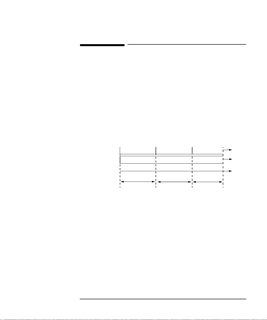
Before running a pointer sequence you can elect to run an initialization
sequence, followed by a cool down period, and then run the chosen
sequence. This is selected using the START INIT softkey shown in the
display on the previous page. Initialized pointer sequences are made up
of three periods: the Initialization Period, the Cool Down P eriod, and the
Sequence (Measurement) Period, an example is given in the following
figure:
Non Periodic Sequence
Periodic Sequence
Initialization Sequence
Initialization
No Pointer Activity
Continuous Sequence
Cool Down
Sequence
Time
Measurement
Period
Note: SINGLE (A1), BURST (A2) and PHASE TRANSIENT(A3) are Non
Periodic Sequences.
Initialization Period
For SINGLE A1, BURST A2 and PHASE TRANSIENT A3 sequences the
initialization sequence consists of 60 seconds of pointer adjustments
applied at a rate of 2 adjustments per second and in the same direction
as the specified pointer sequence.
Cool Down Period
A period following the initialization period which for SINGLE e), BURST
f) and PHASE TRANSIENT sequences is 30 seconds long when no
pointer activity is present.
69

Selecting Test Features
T1.105 A4 and A5, 87-3 Pattern
T1.105/GR-253 Pointer Sequences Explained
Sequence (Measurement) Period
The period following the Cool Down period where the specified pointer
sequence runs continuously.
Periodic Test Sequences
For periodic test sequences (for example “PERIODIC ADD ”) both the 60
second initialization and 30 second cool down periods consist of the same
sequence as used for the subsequent measurement sequence. If the
product of the period T and the selected Optional background pattern
(87+3 or 26+1) exceeds 60 seconds then the longer period is used for the
initialization. For example, if T is set for 10 seconds then the
initialization period may be extended to 900 seconds.
The HP 37717C displays a message indicating which phase
(initialization, cool down or measurement) the transmitter is currently
generating.
NOTE The following conditions apply for pointer sequence generation:
The sequences can only be applied to the SPE pointer when the SPE does
not contain a VT structure, otherwise it is applied to the VT pointer.
Pointer sequence generation is not available when a frequency offset is
being applied to the Line Rate.
The following figure gives an example of a T1.105/GR-253, 87-3 Pointer
Sequence.
Pointer Adjustment
70
No Pointer
Adjustment
87
An Example of a Pointer Sequence
Start of Next
87-3 Pattern
3

Selecting Test Features
T1.105/GR-253 Pointer Sequences Explained
Pointer Sequence Description
T1.105 A1 SINGLE
GR-253 5-29
T1.105 A2 BURST OF 3
GR-253 5-30
T1.105 A3 PHASE
TRANSIENT
GR-253 5031
T1.105 A4 PERIODIC
NORMAL (87-3 Pattern)
GR-253 5-33(b)
T1.105 A4 PERIODIC
NORMAL (Continuous
Pattern) GR-253 5-34(b)
GR-253 5-32(b)
PERIODIC NORMAL (26-1
Pattern)
Periodic Single adjustments, all of the same polarity which is
selectable. Separation between pointer adjustments is fixed at
approximately 30 seconds.
Periodic bursts of 3 adjustments, all of the same polarity which is
selectable. The interval between bursts is fixed at approximately 30
seconds. The interval between adjustments within a burst is set to
the minimum (see Note 2 page 73).
Phase transient pointer adjustment burst test sequence. All
adjustments are of the same polarity, which is selectable. The
interval between bursts is fixed at 30 seconds. Each burst consists
of 7 pointer movement. The first 3 in each burst are 0.25 s apart,
and the interval between the 3 and 4 movement, and each
remaining movement 0.5 seconds.
An 87-3 pattern is selected. The sequence pattern is 87 pointer
movements followed by 3 missing pointer movements. Pointer
polarity is selectable and the time interval between pointer
adjustments settable (see Note 1 page 73).
Provides a continuous sequence of pointer adjustments. The
polarity of the adjustments is selectable, and the time interval
between adjustments can be set (see Note 1).
This selection is only available if you have selected VT1.5 mapping.
The sequence pattern is 26 pointer movements followed by 1
missing pointer movement. Pointer polarity is selectable and the
time interval between pointer adjustments programmable to 200
ms, 500 ms, 1 s, 2 s, 5 s or 10 seconds.
T1.105 A5 PERIODIC ADD
(87-3 Pattern)
GR-253 5-33(c)
An 87-3 pattern is selected. The sequence pattern is 87 pointer
movements followed by 3 missing pointer movements with an added
pointer movement after the 43rd pointer. The spacing between the
added adjustment and the previous adjustment is set to the
minimum, (see Note 2 page 73). Pointer polarity is selectable. The
time interval between pointer adjustments can be set (see Note 1).
Added adjustments occur every 30 seconds or every repeat of the 873 pattern, whichever is longer.
71

Selecting Test Features
T1.105/GR-253 Pointer Sequences Explained
Pointer Sequence Description
T1.105 A5 PERIODIC ADD
(Continuous Pattern)
GR-253 5-34(c)
GR-253 5-32(c)
PERIODIC ADD (26-1
Pattern)
T1.105 A5 PERIODIC
CANCEL (87-3 pattern)
GR-253 5-33(d)
T1.105 A5 PERIODIC
CANCEL (Continuous
Pattern)
GR-253 5-34(d)
Periodic Single adjustments, with selectable polarity and added
adjustment (1 extra). The spacing between the added adjustment
and the previous adjustment is set to the minimum, (see Note 2).
The time interval between pointer adjustments can be set (see Note
1). Added adjustments occur every 30 seconds or every repeat of the
87-3 pattern, whichever is longer.
This selection is only available if you have selected VT1.5 mapping.
The sequence pattern is 26 pointer movements followed by 1
missing pointer movement. The added adjustment occurs 2 ms after
the 13th pointer adjustment. Pointer polarity is selectable and the
time interval between pointer adjustments programmable to 200
ms, 500 ms, 1 s, 2 s, 5 s or 10 s. Added adjustments occur every 30
seconds or every repeat of the 26-1 pattern, whichever is longer.
An 87-3 pattern is selected. The sequence pattern is 87 pointer
movements followed by 3 missing pointer movements with a
cancelled pointer movement at the 87th pointer. Pointer polarity is
selectable, and the time interval between pointer adjustments can
be set (see Note 1). Cancelled adjustments occur every 30 seconds or
every repeat of the 87-3 pattern, whichever is longer.
Periodic Single adjustments, with selectable polarity and cancelled
adjustment (1 less). The time interval between pointer adjustments
can be set (see Note 1). Cancelled adjustments occur every 30
seconds or every repeat of the 87-3 pattern, whichever is longer.
GR-253 5-32(d)
PERIODIC CANCEL (26-1
pattern)
This selection is only available if you have selected VT1.5 mapping.
The sequence pattern is 26 pointer movements followed by 1
missing pointer movement. The cancelled adjustment is the 26th
pointer adjustment, that is the one before the regular gap of 1.
Pointer polarity is selectable and the time interval between pointer
adjustments programmable to 200 ms, 500 ms, 1 s, 2 s, 5 s or 10s.
Cancelled adjustments occur every 30 seconds or every repeat of the
26-1 pattern, whichever is longer.
72

Selecting Test Features
T1.105/GR-253 Pointer Sequences Explained
Pointer Sequence Notes
Note 1: For SPE pointers the sequence interval is selectable from:
7.5 ms, 10, 20, 30, 34 ms
40 to 100 ms in 10 ms steps, 100 to 1000 ms in 100 ms steps
1, 2, 5, 10 seconds.
For VT pointers the sequence interval is selectable from:
200 ms, 500 ms, 1, 2, 5 and 10 seconds.
Note 2: For SPE pointers the minimum spacing between adjustments is 500 us.
For VT pointers the minimum spacing between adjustments is 2 ms.
73

Selecting Test Features
T1.105/GR-253 Pointer Sequences Explained
Table 1 Pointer Sequences Available with Selected Mapping
MAPPING
POINTER SEQUENCE
A1 SINGLE
A2 BURST OF 3
A3 PHASE TRANSIENT
A4 PERIODIC NORMAL(87-3)
A4 PERIODIC NORMAL (Continuous)
PERIODIC NORMAL (26-1)
A5 PERIODIC ADD (87-3)
A5 PERIODIC ADD (Continuous)
PERIODIC ADD (26-1)
A5 PERIODIC CANCEL (g) 87-3
A5 PERIODIC CANCEL (Continuous)
PERIODIC CANCEL 26-1
SPE VT6, VT2 VT1.5
✓✓✓
✓✓✓
✓✓✓
✓
✓✓✓
✓
✓
✓✓✓
✓
✓
✓✓✓
✓
74

Selecting Test Features
Using Pointer Graph Test Function
Using Pointer Graph Test Function
Pointer Graph shows the relative offset during the measurement period.
This allows the time relationship of SPE or VT pointer movements to be
observed. Up to 4 days of storage allows long term effects such as W ander
to be observed. If an alarm occurs during the measurement period, a new
graph starts at the centre of the display (offset zero) after recovery from
the alarm.
TIP: The graph can also be viewed on the display.
HOW TO: 1 Set up the receive SDH interface and payload as required. See “Setting
SONET Receive Interface” page 21.
2 Choose the CAPTURE INTERVAL required.
The capture interval determines the time between captures. Low
values of capture interval should be chosen when a high degree of
pointer movements is expected.
High values of capture interval should be chosen when a low degree of
pointer movements is expected, for example W ander over 1 day, use 5
MINS and Wander over 4 days, use 20 MINS.
If, during a long term measurement (4 days), an event occurs at a
particular time each day, a short term measurement can be made at
RESULTS
SONET RESULTS
75

Selecting Test Features
Using Pointer Graph Test Function
the identified time to gain more detail of the event.
HOW TO: 3 Choose the POINTER UNDER TEST type SPE or VT.
4 Press to start the measurement.
RUN/STOP
TIP: If the event occurs outside normal working hours, a Timed Start
measurement can be made.
1 SEC - display window of approximately 5 minutes.
5 SECS - display window of approximately 25 minutes.
20 SECS - display window of approximately 1 hour 40 minutes.
1 MIN - display window of approximately 5 hours.
5 MIN - display window of approximately 1 day.
20 MIN - display window of approximately 4 days.
76

Selecting Test Features
Stressing Optical Clock Recovery Circuits
Stressing Optical Clock Recovery
Circuits
Description Ideally clock recovery circuits in the network equipment optical
interfaces should recover the clock even in the presence of long strings of
0s. You can check the performance of your optical clock recovery circuits
using the STRESS TEST test function.
The stress test is available at STS-12 and OC-12 if Option 130 or 131 is
fitted. If Options 110/120 are also fitted then the stress test is also
available at STS-12BIN and OC-12.
HOW TO: 1 Set up the SONET transmit interface and payload required.
Choose the required STRESSING PATTERN.
The G.958 test pattern consists of 4 consecutive blocks of data as
follows:
ALL ONES, a PRBS, ALL ZEROS and the first row of section
overhead bytes.
2 If you choose ALL ONES or ALL ZEROS as the stressing pattern,
choose the number of bytes in the BLOCK LENGTH.
77

Selecting Test Features
Generating Automatic Protection Switch Messages
Generating Automatic Protection
Switch Messages
Description You can program the K1 and K2 bytes to exercise the APS functions for
Both LINEAR (GR-253) and RING (GR-1230) topologies.
HOW TO: 1 Set up the SONET transmit interface and payload required. See
“Description” page 6.
2 Choose the TOPOLOGY required.
3 Choose the message to be transmitted.
If LINEAR topology is chosen, choose the CHANNEL, the BRIDGED
CHANNEL NO., the ARCHITECTURE and the RESERVED bits you
require.
If RING topology is chosen, choose the DESTINATION NODE ID, the
SOURCE NODE ID, the type of PATH and the status code (K2 Bits 6>8)
The current TX and RX, K1 and K2, values are displayed for reference
only.
4 Choose DOWNLOAD to transmit the new K1/K2 values.
78

Selecting Test Features
Inserting & Dropping Data Communications Channel
Inserting & Dropping Data
Communications Channel
Description The Data Communications Channel (DCC) of the section and line
overhead can be verified by protocol testing. The Insert and Drop
capability provides access to the DCC via the RS-449 connector on the
front panel of the SDH/SONET module.
DCC INSERT is available on the , ,
display.
DCC DROP is available on the ,
display.
HOW TO: 1 Connect the Protocol Analyzer to the RS449 port on the SDH/SONET
Transmit module.
TRANSMIT
RECEIVE
SONET TEST FUNCTION
SONET TEST FUNCTION
2 Choose the required DCC.
If you choose DCC BYTE POLARITY [NORMAL], the first bit received
in each byte is the first bit dropped (i.e. the most significant).
Choice of NORMAL or REVERSED on the DCC INSERT or DCC
DROP display will take effect on both.
79

Selecting Test Features
Inserting & Dropping Data Communications Channel
80

3
3 Making Measurements

Making Measurements
Using Overhead BER Test Function
Using Overhead BER Test Function
Description You can perform a Bit Error Rate test on chosen bytes of the section, line
and path overhead bytes.
You can access the transmit Overhead BER on the
TEST FUNCTION
display.
TRANSMIT
HOW TO: 1 Set up the SONET transmit interface and payload required.
2 Set up the SONET receive interface and payload required.
3 Choose the overhead byte to be tested on the
TEST FUNCTION
display.
RECEIVE
SONET
SONET
4 Choose the overhead byte to be tested on the
TEST FUNCTION
5 Press to start the test.
RUN/STOP
display.
6 The PRBS pattern can be errored by pressing .
TRANSMIT
SINGLE
82
SONET

Making Measurements
Test Timing
Test Timing
Description There are two aspects to test timing:
Error results may be displayed as short term or cumulative over the
measurement period.If short term error measurements are required, the
short term period may be selected.
The period of the test may be defined or controlled manually.
HOW TO: 1 Select the display.
2 Set the SHORT TERM PERIOD to the timing required for short term
results.
3 Select the type of TEST TIMING required:
For manual control with select [MANUAL].
For a single timed measurement period started with ,
select [SINGLE] and select the test duration.
For a timed period starting at a specified time, select TIMED, select
the test duration and the test START date and time.
RESULTS
TIMING CONTROL
RUN/STOP
RUN/STOP
83

Making Measurements
Making SONET Analysis Measurements
Making SONET Analysis Measurements
Description G.826 analysis results are provided for all relevant SDH/SONET error
sources.
In addition the following results are provided:
Cumulative error count and error ratio
Short Term error count and error ratio
Alarm Seconds
Pointer Values
Frequency
HOW TO: 1 Set up the SONET transmit interface and payload required.
2 Set up the SONET receive interface and payload as required.
3 Press to start the measurement.
4 Y ou can view the analysis results on the
display .
TIP: The measurement will not be affected if you switch between the different
results provided.
84
RUN/STOP
RESULTS
SONET ANALYSIS

Making Measurements
Making PDH Analysis Measurements
Making PDH Analysis Measurements
Description G.821, G.826, M.2100, M.2110 and M.2120 analysis results are provided
for all relevant PDH and PDH Payload error sources.
In addition the following results are provided:
Cumulative error count and error ratio
Short Term error count and error ratio
Alarm Seconds
SIG/BIT Monitor refer to "Monitoring Signaling Bits " page 95
NOTE G.826, M.2100, M.2110 and M.2120 are only available if Option UKJ,
Structured PDH is fitted.
HOW TO: 1 If SDH or SONET (option 120) is chosen as the interface, set up the
Transmit Interface and Payload, and also the Receive Interface and
Payload required.
2 If PDH is chosen as the interface, set up the PDH transmit interface,
and the PDH receive interface required.
3 Press to start the measurement.
RUN/STOP
85

Making Measurements
Making PDH Analysis Measurements
4 If SDH is chosen as the interface, you can view the analysis results on
the display .
RESULTS
PDH PAYLOAD
ERROR ANALYSIS
If PDH is chosen as the interface, you can view the analysis results on
the display.
RESULTS
PDH ERROR ANALYSIS
TIP: The measurement will not be affected if you switch between the different
results provided.
86

Making Measurements
Measuring Jitter
Measuring Jitter
Description: PDH Jitter and PDH error measurements are made simultaneously
when a PDH jitter measurement option is fitted. The measurements are
made on the normal input to the PDH receiver and the interface
selections are the normal PDH Receiver selections.
SDH/SONET Jitter and SDH/SONET error measurements are isolated
individual measurements. The jitter measurement is made on an SDH/
SONET input to the Jitter module.
Cumulative and Short Term results of Jitter Amplitude and Jitter Hits
are provided on the display.
Graph and Text results for Jitter Transfer and Jitter Tolerance are also
provided.
RESULTS
JITTER
HOW TO: 1 If measuring Jitter on a PDH signal, set up the receive PDH interface
for the error measurements. See “Setting PDH Receive Interface”
page 18 and the receive Jitter interface for jitter range threshold and
filters, see“Setting Jitter Receive Interface” page 23.
2 If measuring Jitter on an SDH/SONET signal, set up the receive Jitter
interface. See “Setting Jitter Receive Interface” page 23.
87

Making Measurements
Measuring Jitter
NOTE For Jitter measurements on an SDH/SONET signal you need to set the
Receive interface to SDH/SONET Jitter.
3 Press to start the measurement.
RUN/STOP
4 You can view the Jitter hits and Amplitude results on the
JITTER
display.
RESULTS
88
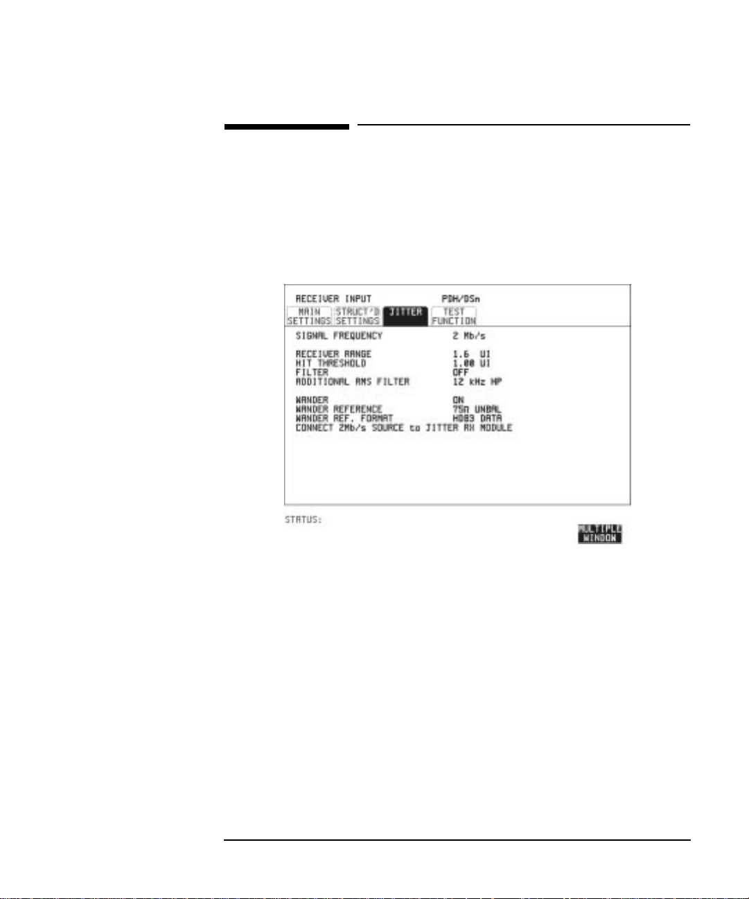
Making Measurements
Measuring Wander
Measuring Wander
Description: Wander measurements are possible when the received PDH interface
signal is 2 Mb/s. The Wander results are displayed in bits and
microseconds. Estimated Bit and Frame slips are also calculated. In
addition a Bar Graph shows the cumulative Wander over the
measurement period.
HOW TO: Make the Measurement
1 Connect a 2 Mb/s REFERENCE (CLOCK or DATA) to the 2M REF IN
port of the Jitter Receiver module.
2 Set up a 2 Mb/s PDH receive interface. See “Setting PDH Receive
Interface” page 18.
3 Choose WANDER [ON].
4 Choose the WANDER REFERENCE impedance.
If the 2 Mb/s Reference is connected to the 2M REF IN 75Ω port,
choose 75Ω UNBAL. If connected to the 120Ω port, choose 120Ω BAL.
5 Choose the WANDER REF FORMAT.
If the 2Mb/s Reference connected to the 2M REF IN port is a data
signal, choose HDB3 DATA.
89
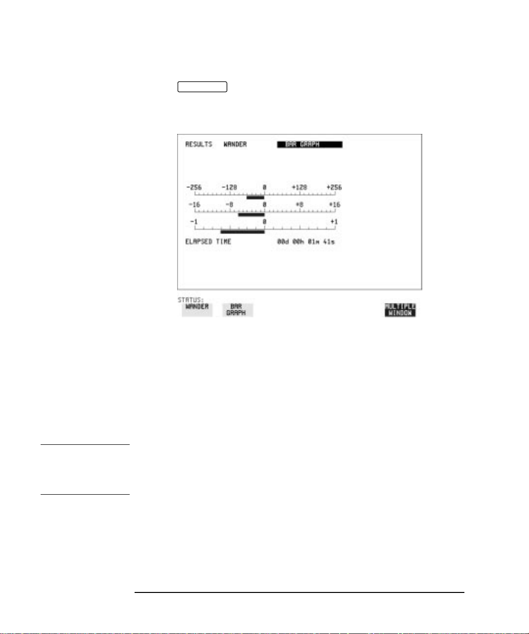
Making Measurements
Measuring Wander
6 Press to start the measurement.
RUN/STOP
HOW TO: View the Results
1 Choose the results type, WANDER or BAR GRAPH.
If Bar Graph is chosen the cumulative wander results are displayed in
graphical form. The Bar Graphs are additive and in the example
shown above the Wander is -70.625 BITS.
2 If WANDER is chosen, choose the units in which the results are
displayed.
TIME displays the wander results in microseconds.
BITS displays the wander results in bits.
NOTE Estimated Bit Slips signify the slippage from the start of the
measurement.
One Estimated Frame Slip corresponds to 256 Bit Slips.
Implied Frequency Offset is calculated from the Wander results.
90
 Loading...