

Page 1

HP 37717C
Communications
Performance Analyzer
Jitter Concept
Guide
Page 2
Copyright HewlettPackard Ltd.1997
All rights reserved.
Reproduction, adaption,
or translation without prior
written permission is
prohibited, except as
allowed under the
copyright laws.
Information in this
document may apply to
modules which use the
VxWORKS TM software.
The VxWORKS TM
software was developed by
Wind River Systems, Inc.,
which has copyright to it.
HP Part No. 37717-90258
First edition, July 97
Printed in U.K.
Warranty
The information contained
in this document is subject
to change without notice.
Hewlett-Packard mak es no
warranty of any kind with
regard to this material,
including, but not limited
to, the implied warranties
or merchanability and
fitness for a particular
purpose.
Hewlett-Packard shall not
be liable for errors
contained herein or for
incidental or
consequential damages in
connection with the
furnishing, performance,
or use of this material.
WARNING
Warning Symbols Used
on the Product
!
The product is marked
with this symbol when the
user should refer to the
instruction manual in order
to protect the apparatus
against damage.
The product is marked
with this symbol to
indicate that hazardous
voltages are present
The product is marked
with this symbol to
indicate that a laser is
fitted. The user should
refer to the laser safety
information in the
Calibration Manual.
Hewlett-Packard Limited
Communications Measurements Division
South Queensferry
West Lothian, Scotland EH30 9TG
Page 3

Jitter Concept Guide
HP 37717C
Communications
Performance Analyzer
Page 4

About This Book
The information on Jitter testing in this book covers the following subjects::
• An Introduction to Jitter, the Jitter modules and their features.
• Measurement examples.
• Measurement result definitions
• Logging messages
• Self test error codes
For some operations and measurements, information from one of the associated
books listed at the rear of this guide may be required.
iv
Page 5

Contents
1 Introduction to Jitter Testing
Introduction to Jitter 2
Option A3L [A3M] PDH & STM-1 Electrical Jitter Measurements 3
Option A3V [A3W] PDH & STM-1 Optical & Electrical Jitter Measurements 4
Option A3N [A3P] PDH, STM-1 Electrical & Optical & STM-4 Optical Jitter Measurements 5
Option A3K [A3Q] Jitter & Wander Generator 6
2 Jitter Testing
Multiplexer Jitter Tolerance 8
Wander and Slips 13
Desynchroniser Stress 18
SDH Jitter Tolerance 21
In Service SDH Jitter 24
Tributary Mapping Jitter 26
Selective Jitter Transfer Measurement 29
In Service ATM Jitter 36
3 Result Definitions
Jitter Results 40
v
Page 6

Contents
4 Jitter Logging Messages
Logging Devices 42
Results Logging 42
5 Jitter Self Test Error Codes
vi
Page 7

1
“Introduction to Jitter” page 2
“Option A3L [A3M] PDH & STM-1 Electrical Jitter Measurements” page 3
“Option A3V [A3W] PDH & STM-1 Optical & Electrical Jitter Measurements” page 4
“Option A3N [A3P] PDH, STM-1 Electrical & Optical & STM-4 Optical Jitter Measurements” page 5
“Option A3K [A3Q] Jitter & Wander Generator” page 6
1 Introduction to Jitter Testing
.
Page 8

Introduction to Jitter Testing
Introduction to Jitter
Introduction to Jitter
Errors will occur in a digital signal if jitter at the input of Network Equipment
exceeds a threshold value. It is important to check that the maximum input jitter , that
can be tolerated by that equipment, meets the ITU-T standards for maximum
tolerable input jitter.
Excessive jitter not only causes errors, alarms and loss of synchronization but
directly affects quality of service within the network.
During the transition from a PDH network to mixed PDH/SDH networks, tight
control of jitter levels is essential, especially as new sources of jitter emerge, caused
by the mapping process and network synchronization problems resulting in pointer
movements. The pointer movements cause trib utary jitter at the PDH output ports of
the network element.
Cascading SDH regenerators on long distance links makes a build up of jitter
unavoidable. It is vital to keep the jitter accumulation at the line side of the network
element to a minimum as the SDH line rate is increasingly being used for
synchronization purposes within SDH networks. Excessive line jitter may cause
timing problems between network elements resulting in errors and pointer
movements.
ATM network elements such as switches, routers, multiplexers and cross connects
are also susceptible to jitter and it is therefore important to minimize jitter in ATM
networks.
Wander is an extremely slow variation in the timing of the pulse stream. Excessive
amounts of wander in a network will cause timing problems resulting in pointer
movements. Wander measurements are made at 2 Mb/s, using an external 2 Mb/s
MTS (ITU-T G.811) as a reference. Estimated frame and bit slips are also indicative
of wander effects.
The HP 37717C provides comprehensive Jitter testing at all PDH and SDH rates
from 2 Mb/s to 622.08 Mb/s (STM-4).
PDH Jitter Measurement
Jitter may be measured on the normal PDH Input and results displayed using
RESULTS; JITTER.
SDH Jitter Measurement
Jitter may be measured on the signal at the SDH JITTER INPUT and results
displayed on the RESULTS; SDH JITTER and RESULTS; AUTO TOLER displays.
2
Page 9
Introduction to Jitter Testing
Option A3L [A3M] PDH & STM-1 Electrical Jitter Measurements
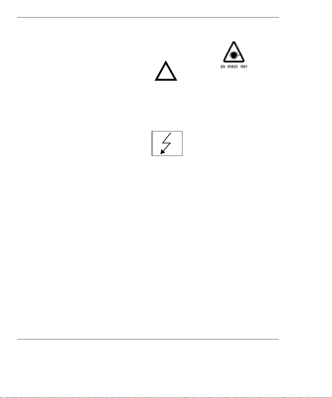
Option A3L [A3M] PDH & STM-1 Electrical
Jitter Measurements
Option A3L provides Jitter measurement at STM-1 Electrical rate and PDH
rates of 2 Mb/s, 8 Mb/s, 34 Mb/s and 140 Mb/s. Compliance to ITU-T O.171
and testing to ITU-T G.825/G.958 is provided.
To measure jitter connect the PDH signal to the PDH IN port of the PDH
module (Options UKK, UKJ and UKN) or the STM-1 Electrical signal to the
STM-1E IN of the A3L module.
Jitter measurements are available at all PDH rates and STM-1 Electrical
rate:
Jitter Hit Count
Jitter Hit Seconds
Jitter Hit Free Seconds
Peak Jitter (Positive and Negative)
Peak to Peak Jitter
Peak rms Jitter
Option A3L [A3M]
Automatic Jitter Transfer with narrowband selective filtering, in
conjunction with Option UHK or A3K, Jitter Generation.
The user can control the number of frequency points at which Jitter is
generated, up to 55.
Fixed input masks, ITU-T G.823 for PDH and ITU-T G.958 for SDH, are
provided. A user defined mask is also available.
Jitter Transfer results are displayed in tabular form and in Graphical form.
The ITU-T pass mask is also displayed on the graph.
Wander measurements are only available at 2.048 Mb/s:
Peak Wander (Positive and Negative)
Peak to Peak Wander
Estimated Bit Slips
Estimated Frame Slips
Implied Frequency Offset
A graphical display of Wander is also provided.
DEMOD OUT connector provides a Demodulated Jitter output.
3
Page 10
Introduction to Jitter Testing
Option A3V [A3W] PDH & STM-1 Optical & Electrical Jitter
Measurements
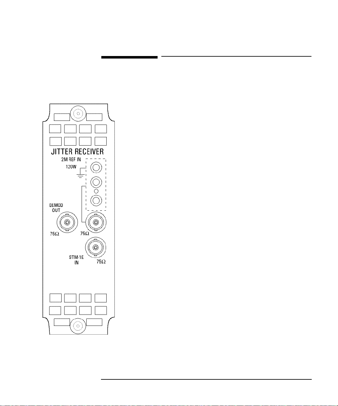
Option A3V [A3W] PDH & STM-1 Optical &
Electrical Jitter Measurements
Option A3V provides Jitter measurement at STM-1 Optical and electrical rate
and PDH rates of 2 Mb/s, 8 Mb/s, 34 Mb/s and 140 Mb/s. Compliance to ITUT O.171 and testing to ITU-T G.825/G.958 is provided.
To measure jitter connect the PDH signal to the PDH IN port of the PDH
module (Options UKK, UKJ and UKN) or the STM-1 Electrical signal to the
STM-1E IN of the A3V module or the STM-1 Optical signal to STM-1/STM4 IN of the A3V module.
Jitter measurements are available at all PDH rates and STM-1:
Jitter Hit Count
Jitter Hit Seconds
Jitter Hit Free Seconds
Peak Jitter (Positive and Negative)
Peak to Peak Jitter
Peak rms Jitter
Option A3V [A3W]
Automatic Jitter Transfer with narrowband selective filtering, in
conjunction with Option A3K or UHK, Jitter Generation.
The user can control the number of frequency points at which Jitter is
generated, up to 55.
Fixed input masks, ITU-T G.823 for PDH and ITU-T G.958 for SDH, are
provided. A user defined mask is also available.
Jitter Transfer results are displayed in tabular form and in Graphical form.
The ITU-T pass mask is also displayed on the graph.
Wander measurements are only available at 2.048 Mb/s:
Peak Wander (Positive and Negative)
Peak to Peak Wander
Estimated Bit Slips
Estimated Frame Slips
Implied Frequency Offset
A graphical display of Wander is also provided.
DEMOD OUT connector provides a Demodulated Jitter output.
4
Page 11

Introduction to Jitter Testing
Option A3N [A3P] PDH, STM-1 Electrical & Optical & STM-4 Optical
Jitter Measurements
Option A3N [A3P] PDH, STM-1 Electrical &
Optical & STM-4 Optical Jitter Measurements
Option A3N provides Jitter measurement at STM-1 Optical and electrical
rate, STM-4 Optical rate and PDH rates of 2 Mb/s, 8 Mb/s, 34 Mb/s and 140
Mb/s. Compliance to ITU-T O.171 and testing to ITU-T G.825/G.958 is
provided.
To measure jitter connect the PDH signal to the PDH IN port of the PDH
module (Options UKK, UKJ and UKN) or the STM-1 Electrical signal to the
STM-1E IN of the A3N module or the STM-1/STM-4 Optical signal to
STM-1/STM-4 IN of the A3N module.
Jitter measurements are available at all PDH rates, STM-1 Optical and
electrical rate and STM-4 Optical rate:
Jitter Hit Count
Jitter Hit Seconds
Jitter Hit Free Seconds
Peak Jitter (Positive and Negative)
Peak to Peak Jitter
Peak rms Jitter
Option A3N [A3P]
Automatic Jitter Transfer with narrowband selective filtering, in
conjunction with Option A3K or UHK, Jitter Generation.
The user can control the number of frequency points at which Jitter is
generated, up to 55.
Fixed input masks, ITU-T G.823 for PDH and ITU-T G.958 for SDH, are
provided. A user defined mask is also available.
Jitter Transfer results are displayed in tabular form and in Graphical form.
The ITU-T pass mask is also displayed on the graph.
Wander measurements are only available at 2.048 Mb/s:
Peak Wander (Positive and Negative)
Peak to Peak Wander
Estimated Bit Slips
Estimated Frame Slips
Implied Frequency Offset
A graphical display of Wander is also provided.
DEMOD OUT connector provides a Demodulated Jitter output.
5
Page 12
Introduction to Jitter Testing
Option A3K [A3Q] Jitter & Wander Generator
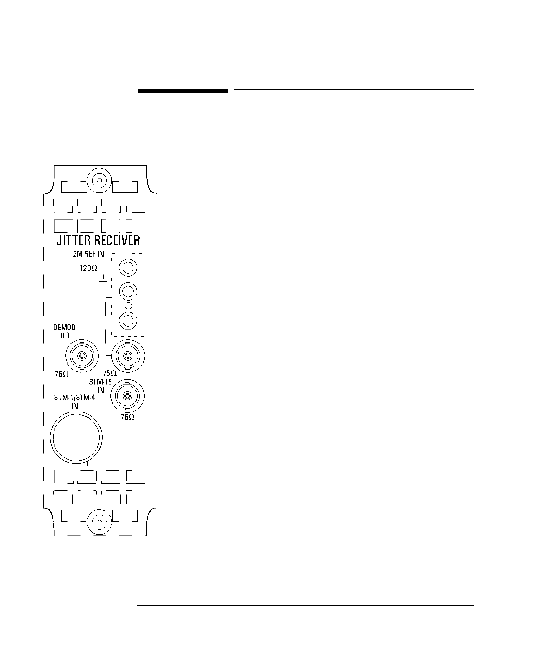
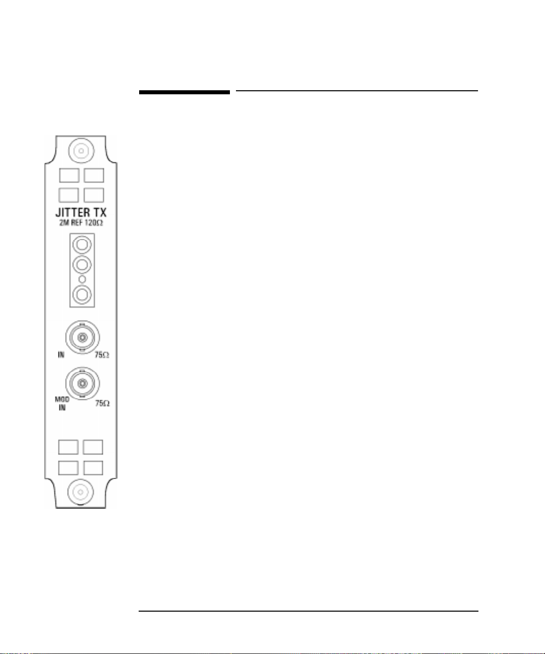
Option A3K [A3Q] Jitter & W ander Generator
Option A3K provides Jitter Generation at all ETSI rates, 2 Mb/s, 8 Mb/s, 34 Mb/s, 140
Mb/s, STM-1 and STM-4 depending on which PDH and SDH options are fitted.
Allows the generation of User Definable Jitter as follows:
Spot frequency Jitter within the ITU-T mask.
Swept frequency Jitter within the ITU-T mask.
Automatic Jitter Tolerance testing of PDH and SDH networks covering high and low
Q systems using fixed jitter tolerance masks. Peak to Peak Jitter and Modulating
frequencies as per ITU-T G.823 (PDH) and ITU-T G.958 (SDH).
The Automatic Jitter Tolerance results are plotted in graphical form relative to the ITUT mask.
The User can control:
the number of frequency points at which Jitter is generated, up to 55.
the Dwell time - time taken at each frequency point.
the Delay time - delay at each frequency point before jitter is generated.
the Bit error threshold - determines the threshold for the Jitter Tolerance
PASS/FAIL decision.
High or Low Q Factor selection (2 Mb/s and 8 Mb/s only)
the type of mask A or B (SDH only)
the Test Pattern
ption A3K
[A3Q]
The jitter modulation can be sourced internally or from an External source. The
external modulation is connected to the MOD IN port.
Allows testing to ITU-T G.825.
Full ITU-T O.171 generation capability from 10 µΗz to 5 MHz
Provides stimulus for Jitter Transfer measurements.
Peak to Peak Jitter and Modulating frequencies as per ITU-T G.823 (PDH) and ITU-T
G.958 (SDH).
Provides Wander Generation at 2 Mb/s, STM-1 and STM-4 depending on which
PDH and SDH options are fitted. An external clock must be connected to the 2M REF
input.
The 2M REF input can be used as an external clock for 2.048 Mb/s PDH transmission.
The wander modulation can be sourced internally or from an external source. The
external modulation is connected to the MOD IN port.
Allows the generation of User Definable Spot frequency Wander within the ITU-T
mask
6
Page 13

2
“Multiplexer Jitter Tolerance” page 8
“Wander and Slips” page 13
“Desynchroniser Stress” page 18
“SDH Jitter Tolerance” page 21
“In Service SDH Jitter” page 24
“Tributary Mapping Jitter” page 26
“Selective Jitter Transfer Measurement” page 29
“In Service ATM Jitter” page 36
2 Jitter Testing
This Chapter gives examples of the instrument
operation in typical Jitter test applications.
NOTE that actual instrument displays may vary
depending on instrument option.
Page 14

Jitter Testing
Multiplexer Jitter Tolerance
Multiplexer Jitter Tolerance
Application
It is important that network equipment can operate correctly in the presence of
certain amounts of jitter. ITU-T has specified tolerance masks of jitter amplitude
against jitter frequency which all network equipment must be able to withstand and
provide error free operation.
Jitter is applied at the ITU-T specified jitter frequencies and the amplitude increased
beyond the ITU-T mask limits until errors occur or the maximum possible jitter
amplitude is reached. The resulting amplitude levels are plotted relativ e to the mask
to determine the network elements jitter tolerance.
Default (Known State) Settings
It can be advisable to set the HP 37717C to a known state prior to setting up to make
a measurement. This clears all previous settings and provides a clearly defined
instrument state. The default settings are set by selecting
STORED SETTINGS
STORED SETTING NUMBER 0 and pressing .
OTHER
RECALL
Test Setup Procedure (Jitter Tolerance Test)
The following Option must be fitted to the HP 37717C to perform this test :
• A3K [A3Q] - Jitter Generation A3L[A3M], A3V[A3W] or A3N[A3P] Jitter
Measurement
• UKJ or UKK - PDH Module
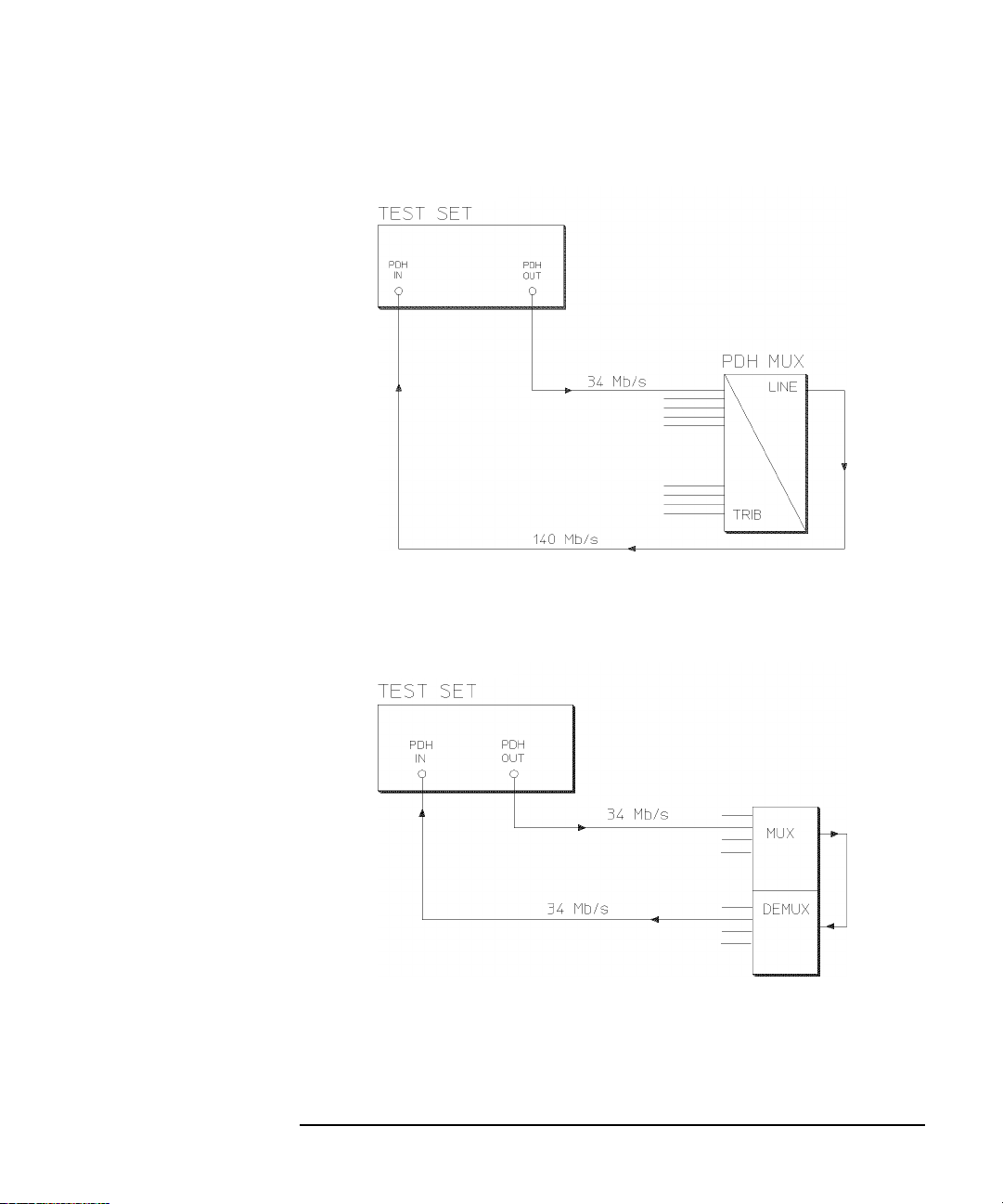
This setup procedure is based on 34 Mb/s CMI, PRBS test data with jitter
terminated in 75 Ω. The HP 37717C Automatic jitter tolerance feature is used and
the results plotted on the ITU-T mask.
8
Page 15
Jitter Testing
Multiplexer Jitter Tolerance
Structured PDH Jitter Tolerance Test
This test can be performed using the Unstructured PDH Option UKK but the
network equipment must be looped back at the higher rate.
Unstructured PDH Jitter Tolerance Test
9
Page 16
Jitter Testing
Multiplexer Jitter Tolerance
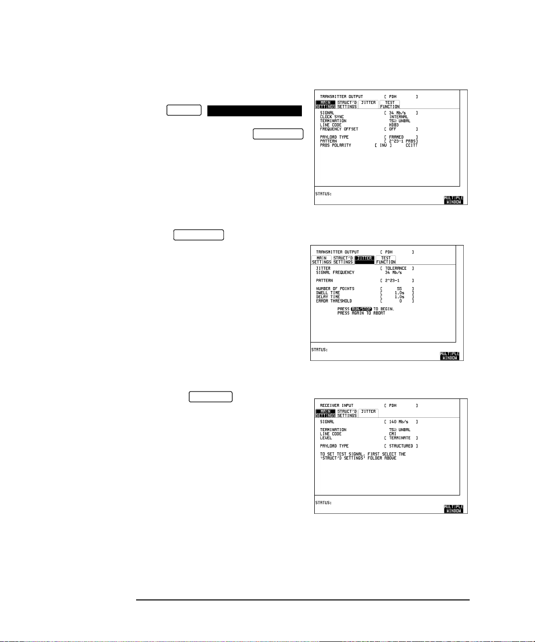
1. Connect the HP 37717C to the network
equipment.
Set the
OTHER
SETTINGS CONTROL
TRANSMITTER AND RECEIVER to
INDEPENDENT and set the
TRANSMIT
display MAIN SETTINGS as shown
opposite.
PAYLOAD TYPE, PATTERN and PRBS
POLARITY selections should match the
reqirement of the network equipment.
2. Select JITTER and set
TRANSMIT
up the display as shown opposite.
The Jitter Tolerance example shown will
take approximately 10 minutes to
complete.
3. Set up the display MAIN
RECEIVE
SETTINGS as shown opposite.
10
Page 17
Jitter Testing
Multiplexer Jitter Tolerance
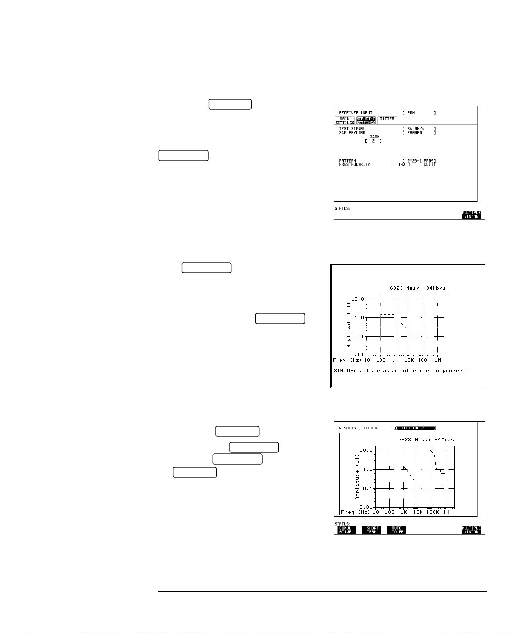
4. Set up the STR UCTURED
RECEIVE
SETTINGS display as shown opposite.
34M PAYLOAD selection should match
the PAYLOAD TYPE selection on the
TRANSMIT
MAIN SETTINGS display.
Run the Test (Jitter Tolerance)
Press to start the
RUN/STOP
measurement.
The measurement takes approximately
ten minutes to complete and its progress
can be monitored on the
TRANSMIT
display.
At the end of the test the results can be
viewed on the display.
The results on the display are
cleared when is pressed but
the display remains available
RESULTS
RESULTS
TRANSMIT
TRANSMIT
until the next Jitter T olerance measurement
is made.
11
Page 18

Jitter Testing
Multiplexer Jitter Tolerance
If Option A3B or Option A3D Remote Control is fitted the Jitter Tolerance Mask
results can be logged to an External printer .
To Log the Auto Tolerance plot and the results which make up the Jitter Auto
Tolerance plot:
On the display, LOGGING SETUP , select the
OTHER
LOGGING DEVICE
required logging device under LOGGING PORT .
On the CONTROL display, select LOGGING [ON] .
On the display:
for PDH Jitter select RESULTS ; and press
for SDH Jitter, select RESULTS; and press .
OTHER
RESULTS
PRINT NOW
LOGGING
.
JITTER
AUTO TOLER
AUTO TOLER
PRINT NOW
12
Page 19

Jitter Testing
Wander and Slips
Wander and Slips
Application
The ITU-T specify the frequency limits within which network equipment clocks
should operate. However when network equipment from different manufacturers is
connected together errors in transmission may occur due to timing differences.
To avoid this problem Master Timing sources are typically used as a reference
timing source for all network equipment. The timing reference is distributed
throughout the network as a 2 Mb/s signal.
Problems may arise due to wrongly configured equipment running on internal
clocks or at the junction of different operators network equipment.
Because the timing sources may operate at slightly different frequencies and exhibit
long term frequency drift then phase difference (Wander) may occur, between the
incoming data and the network equipment. This causes "Bit Slips" in the network
equipment buffers and results in frames being repeated or deleted thus reducing the
efficiency of data transfer.
Default (Known State) Settings
It is advisable to set the HP 37717C to a known state before setting up a
measurement. This clears all previous settings and provides a clearly defined
instrument state. The default settings are set by selecting
STORED SETTINGS
Wander and Slips Test Setup Procedure
The following Options must be fitted to the HP 37717C to perform this test :
• A3L or A3V or A3N - Jitter + Wander Measurement and Estimated Slips
• UKJ or UKK - PDH Module
This measurement is made on live traffic and is interfaced at the line terminal
equipment monitor point. The HP 37717C is used in a receive only mode to measure
the Wander and Estimated Bit Slips.
A SINGLE test period of 24 HOURS is used and use of a printer for the recording of
results and alarms is included. A graphical record of the results can be viewed on the
HP 37717C display at the end of the test period.
GRAPH
STORED SETTING NUMBER 0 and pressing .
OTHER
RECALL
13
Page 20

Jitter Testing
Wander and Slips
Wander and Slips Test
1. Select and set up the display
RECEIVE
as shown opposite.
Selections of TERMINATION, LINE
CODE and PAYLOAD TYPE should
match those of the network equipment.
2. Select the printer and set up the
OTHER
LOGGING
display as shown
opposite.
LOGGING PERIOD and LOG ERROR
SECONDS selections can be modified
according to the users requirements.
14
Page 21

Jitter Testing
Wander and Slips
3. Set up the
TIMING CONTROL
RESULTS
display as shown
opposite.
The STORAGE selection enables the
graphics. To disable graphics select
STORAGE [OFF].
Graphics can be stored to the instrument
store - INTERNAL or to DISK.
4. Select .
WANDER
BAR GRAPH
RESULTS
is selected but or
WANDER
BIT SLIPS
may be selected without
affecting the measurement.
Run the Test (Wander and Slips)
1. Press until the Monitor
SIGNAL IN
indicator, above the key, is lit.
2. Connect the PDH IN port to the line terminal equipment monitor point.
3. Connect the network master timing source to the HP 37717C 2 Mb/s
REFERENCE input.
If no reference signal is connected to the HP 37717C then the status message "NO
REF" is displayed.
4. Press to start the measurement.
RUN/STOP
15
Page 22

Jitter Testing
Wander and Slips
If is selected the current
BAR GRAPH
wander measurements are displayed in
graphical form. Three positive and
negative sliding bar graphs, of ± 1 UI,
± 16 UI and ± 256 UI, are displayed.
The Bar Graph displays are additive - in
this example -1.125 UI.
• The measurement results and alarms are available on the display
RESULTS
during the test period.
• The test can be halted at any time by pressing .
RUN/STOP
At the End of the Test (Wander and Slips)
• The Date and Time the test started and the instrument setup are logged on the
printer.
• Any alarms which occur during the test period will be logged on the printer.
• At the end of the test period a complete set of results are logged on the printer.
• A graphical record of the results during the test period can be viewed on the
GRAPH
display. If Remote Control option 1A8 (HP-IB) or 1CW (RS-232-C),
or A3B or A3D is fitted the graph results can be logged to an external printer, at
a later date. See Graphics and External HP 550C DeskJet Printer in the
Masinframe Operating Manual.
• Results and Alarm summaries can be viewed on the display.
GRAPH
The total graphics store capacity is normally 20,000 events. An event is the
occurrence of an error or an alarmThe resolution, determined by the selection made
under STORAGE on the display, affects the ZOOM capability when
RESULTS
viewing the bar graphs. If 1 SECOND is selected all resolutions are available under
ZOOM.
If 1 MIN is selected only 1 MIN/BAR, 15 MINS/BAR and 60 MINS/BAR are
available.If 15 MINS is selected only 15 MINS/BAR and 60 MINS/BAR are
available. If 1 HOUR is selected only 60 MINS/BAR is available.
Up to 10 sets of graphical results can be stored. If an attempt is made to store more
than 10 sets of results, then a first in first out policy is operated and the oldest set of
16
Page 23

Jitter Testing
Wander and Slips
results will be lost. If graphics are enabled and a test is run which exceeds the
remaining storage capacity, then some previously stored graphical results will be
lost.
T o prev ent accidental overwriting of pre viously stored results the graphics capability
should be disabled, when graphical results are not required, by selecting STORAGE
[OFF] on the display.
RESULTS
17
Page 24

Jitter Testing
Desynchroniser Stress
Desynchroniser Stress
Application
At the boundary of the SDH network the 2 Mb/s or 140 Mb/s payload is demapped
from the SDH signal. Pointer adjustments in the SDH signal may cause high levels
of tributary jitter in the output payload. Excessive amounts of tributary jitter will
result in errors.
The desynchronizing phase lock loop of the network element should minimize the
level of tributary jitter in the payload but correct operation under stress conditions
must be verified.
The desynchronizing phase lock loop can be stressed by adding pointer movement
sequences (defined in ITU-T standard G.783) to the SDH signal such that the test
VC-4 or TU moves with respect to the SDH frame.
A jitter measurement is made to verify that the desynchroniser output jitter is within
the required specification.
Default (Known State) Settings
It is advisable to set the HP 37717C to a known state before setting up a
measurement. This clears all previous settings and provides a clearly defined
instrument state. The default settings are set by selecting
STORED SETTINGS
Desynchroniser Stress Test Setup Procedure
The following options must be fitted to the HP 37717C to perform this test:
• UKK or UKJ - PDH module
• A3L or A3V or A3N - Jitter measurement module
• A3R - SDH module
• UH1 STM-1 or 130 or 131 - STM-0/1/4 Optical interface
The HP 37717C PDH/SDH test set transmits an STM-4 optical signal carrying 2
Mb/s payload. Pointer movement sequences are added in a controlled manner.
The desynchroniser output is returned to the HP 37717C and a jitter measurement is
performed on the demapped 2 Mb/s signal.
18
STORED SETTING NUMBER 0 and pressing .
OTHER
RECALL
Page 25

Jitter Testing
Desynchroniser Stress
Desynchroniser Stress
1. Connect the HP 37717C to the network
equipment.
Set the
OTHER
SETTINGS CONTROL
TRANSMITTER AND RECEIVER to
INDEPENDENT and set the
TRANSMIT
SDH display as shown opposite.
The CLOCK SYNC selection determines
the synchronization source for the
TRANSMIT clock. If
EXTERNAL MTS
is selected a 2 Mb/s reference must be
connected to the 2M REF IN port.
The format can be CLOCK or DATA.
2. Set up the TEST
TRANSMIT
FUNCTION display as shown opposite.
Pointer adjustments are made every 10 ms
with an extra ADDED adjustment as
defined in ITU-T standard G.783.
Pointer sequences are started by selecting
POINTER SEQUENCES .
STARTED
19
Page 26

Jitter Testing
Desynchroniser Stress
3. Set up the JITTER
RECEIVE
PDH
display as shown opposite.
If Jitter filtering is required select from the
softkey menu.
4. Set up the TIMING
RESULTS
CONTROL display as shown opposite.
Start the Desynchroniser Stress Test
1. Press to start the Jitter
RUN/STOP
measurement. .
Jitter Hits can be viewed without affecting
the measurement.
20
Page 27

Jitter Testing
SDH Jitter Tolerance
SDH Jitter Tolerance
Application
It is important that network equipment can operate correctly in the presence of
certain amounts of jitter. ITU-T has specified tolerance masks of jitter amplitude
against jitter frequency which all network equipment must be able to withstand and
provide error free operation.
Jitter is applied at the ITU-T specified jitter frequencies and the amplitude increased
until errors occur or the mask limit is reached. These amplitude levels are plotted on
the mask to determine the network elements jitter tolerance.
Default (Known State) Settings
It can be advisable to set the HP 37717C to a known state prior to setting up to make
a measurement. This clears all previous settings and provides a clearly defined
instrument state. The default settings are set by selecting
STORED SETTINGS
STORED SETTING NUMBER 0 and pressing .
OTHER
RECALL
Test Setup Procedure (Jitter Tolerance Test)
The following Option must be fitted to the HP 37717C to perform this test :
• UHK - Jitter Generation
• UKJ or UKK - PDH Module
• A3R - SDH Module
• UH1, 130 or 131 - Optical Interface Module
This setup procedure is based on STM-4 optical test signal with jitter terminated in
75 Ω. The HP 37717C Automatic jitter tolerance feature is used and the results
plotted on the ITU-T mask.
21
Page 28

Jitter Testing
SDH Jitter Tolerance
TEST SET
PDH IN
STM-1/STM-4
OUT
STM-4 OPT
2 Mb/s
1. Connect the HP 37717C to the network
equipment.
Set the
OTHER
SETTINGS CONTROL
TRANSMITTER AND RECEIVER to
INDEPENDENT and set the
TRANSMIT
SDH display as shown opposite.
CLOCK SYNC, STM-1 UNDER TEST
and PAYLOAD selections can be
modified according to the users
requirements.
ADD
DROP
MUX
Select JITTER and set
TRANSMIT
SDH
up the display as shown opposite.
This Auto Tolerance example will take
approximately nine minutes to complete.
22
Page 29

Jitter Testing
SDH Jitter Tolerance
Set up the MAIN
RECEIVE
PDH
SETTINGS display as shown opposite.
Run the Test (SDH Jitter Tolerance)
Press to start the
RUN/STOP
measurement.
The measurement takes approximately
nine minutes to complete and its
progress can be monitored on the
TRANSMIT
display.
At the end of the test the results can be
viewed on the display.
The results on the display
are cleared when is pressed
but the display remains
RESULTS
TRANSMIT
TRANSMIT
RESULTS
available until the next Jitter Tolerance
measurement is made.
To Log the Auto Tolerance plot : Select
the required logging device on the
OTHER
LOGGING
LOGGING [ON]. Select
JITTER AUTO TOLER
PRINT NOW
.
display..Select
RESULTS
and press
23
Page 30
Jitter Testing
In Service SDH Jitter
In Service SDH Jitter
Application
It can be useful at the installation or field trial stage of SDH rings or linear networks
to verify the networks tolerance to jitter under simulated Live Traffic conditions and
monitor its effects on the network equipment i.e Alarms particularly OOF and LOF.
Default (Known State) Settings
It can be advisable to set the HP 37717C to a known state prior to setting up to make
a measurement. This clears all previous settings and provides a clearly defined
instrument state. The default settings are set by selecting
STORED SETTINGS
STORED SETTING NUMBER 0 and pressing .
Test Setup Procedure (In Service SDH Jitter)
The following Option must be fitted to the HP 37717C to perform this test :
• A3K - Jitter Generation
OTHER
RECALL
ADD
DROP
MUX
• UKJ or UKK - PDH Module
• A3R - SDH Module
• UH1, 130 or 131 - Optical Interface Module
In this set up the received SDH signal has Jitter added and is retransmitted via SDH
THRU mode. The Swept Mask feature is used and the HP 37717C "sweeps" through
the jitter mask, adjusting the jitter amplitude according to the jitter frequency. The
network equipment alarms are monitored particularly OOF and LOF.
TEST SET
STM-1 IN
STM-1 OPT
STM-1 OUT
STM-1 OPT
ADD
DROP
MUX
24
Page 31

Jitter Testing
In Service SDH Jitter
Select and set up the
RECEIVE
SDH
display as shown opposite.
PAYLOAD and PAYLOAD TYPE
selections can be modified according to the
users requirementst.
Select and set up the
TRANSMIT
SDH
display as shown opposite.
Run the Test (In Service SDH Jitter)
Select JITTER and set
TRANSMIT
SDH
up the display as shown opposite.
When JITTER MASK [SWEPT] is
selected the HP 37717C will "sweep"
through the jitter mask adjusting amplitude
according to the Jitter frequency.
Monitor the network alarms, particularly
Out Of Frame and Loss Of Frame.
25
Page 32

Jitter Testing
Tributary Mapping Jitter
Tributary Mapping Jitter
Application
Tributary Mapping jitter occurs during the mapping and demapping process inside
SDH network equipment as the PDH signal is mapped into its Virtual Container.
The method used for mapping an asynchronous 2 Mb/s into a VC-12 provides a
number of opportunities to justify the 2 Mb/s data. The justification process allows
for variations between the 2.048 Mb/s clock and the clock timing the synchronous
network. This process however introduces jitter into the tributary signal when it is
demapped from the VC-12.
Tributary Mapping jitter has four basic characteristics:
1 It is low in amplitude (ITU-T G.783 specifications listed below)
TU-T G.783 Mapping Jitter Specifications.
Payload Offset (ppm) Measurement Bandwidth Maximum Jitter (UI pk-pk)
2 Mb/s
34 Mb/s
139 Mb/s
± 50
± 20
± 15
18 - 100 kHz 0.08
10 - 800 kHz 0.08
10 - 3500 kHz 0.08
2 It is relatively high frequenc y (and can therefore be suppressed by the SDH NE’ s
de-synchronizer).
3 It varies in amplitude as the PDH tributary frequenc y is offset relative to the VC-
n. This is due to changes in the mappings "bit-stuff justification" ratio to
compensate for such offsets.
4 The peak mapping jitter occurs at a small offset from 0 ppm (PDH tributary
relative to VC-n).
26
Page 33

Jitter Testing
Tributary Mapping Jitter
Default (Known State) Settings
It can be advisable to set the HP 37717C to a known state prior to setting up to make
a measurement. This clears all previous settings and provides a clearly defined
instrument state. The default settings are set by selecting
STORED SETTINGS
STORED SETTING NUMBER 0 and pressing .
OTHER
RECALL
Test Setup Procedure (Tributary Mapping Jitter)
The following Option must be fitted to the HP 37717C to perform this test :
• A3L or A3V or A3N - Jitter Receiver
• UKJ or UKK - PDH Module
• A3R - SDH Module
• UH1, 130 or 131 - Optical Interface Module
In this set up Frequency Offset is added to a TU12 tributary within an STM-4 SDH
signal. A Jitter measurement is performed on the received TU12 tributary.
TEST SET
PDH IN
STM-4
OUT
ADM
STM-4
2 MHz MTS
Clock
2 Mb/s
Tributary Mapping Jitter Test
27
Page 34

Jitter Testing
Tributary Mapping Jitter
Connect the HP 37717C to the network
equipment.
Set the
OTHER
SETTINGS CONTROL
TRANSMITTER AND RECEIVER to
INDEPENDENT and set the
TRANSMIT
SDH display as shown opposite.
The 2M OFFSET can be varied during the
test.
Select and set up the
RECEIVE
PDH
display as shown opposite.
TERMINATION and LINE CODE
selections should matc that of the network
equipment.
STM-1 UNDER TEST, TU PAYLOAD,
PATTERN, PRBS POLARITY and
PATTERN IN OTHER TU’S selections
can be modifed according to the users
requirements.
Select JITTER and set
RECEIVE
PDH
up the display as shown opposite.
Any filter can be selected from the softkey
menu.
Run the Test (Tributary Mapping Jitter)
Press to start the Jitter measurement.
RUN/STOP
The Jitter Amplitude and Jitter Hits results can be viewed on the display.
RESULTS
28
Page 35

Jitter Testing
Selective Jitter Transfer Measurement
Selective Jitter Transfer Measurement
The problem with many SDH jitter analyzers is the fact that their receivers are
wideband receivers and are not able to measure within a sufficiently narrow
bandwidth. The reason is that these instruments are designed to measure peak to
peak jitter in the transmission network for troubleshooting purposes and are not
designed to make selective jitter measurements. The jitter analyzer just measures the
peak-peak value of the incoming jitter over a wide frequency range. The problem
occurs when testing the jitter transfer of real network equipment i.e. SDH
regenerators.
The regenerator produces intrinsic jitter and this disturbs the measurement as the
jitter receiver cannot determine whether it is measuring the jitter produced by the
jitter analyzers transmitter or the intrinsic jitter which is generated, at a different
frequency , by the re generator . The problem is greatest at the higher jitter modulating
frequencies when the amount of jitter generated, as per ITU-T G.958, is much
smaller. The measurement is corrupted by the higher amplitude intrinsic jitter
generated by the regenerator at lower frequencies and incorrectly measured by the
analyzer.
The accurate method for measuring jitter transfer requires a selective measurement.
The HP 37717C uses narrow band filtering in the jitter receiver which allows
selection and measurement of the relevant jitter components. This provides the
capability to measure jitter selectively and provide accurate and repeatable results.
Jitter Transfer is performed to ITU-T G.823/G.958 with Graphical and Tabular
results. The input jitter can conform to ITU-T G.823/G.958 or be user defined.
Default (Known State) Settings
It can be advisable to set the HP 37717C to a known state prior to setting up to make
a measurement. This clears all previous settings and provides a clearly defined
instrument state. The default settings are set by selecting
SETTINGS RECALL
Test Setup Procedure (Jitter Transfer Test)
The following Options must be fitted to the HP 37717C to perform this test:
• A3K [A3Q] - Jitter Generation
• A3L or A3V or A3N - Jitter Measurement
• A3R - SDH Module
• UH1 or 130 or 131 - Optical Interface
STORED SETTING NUMBER 0 and pressing .
OTHER
STORED
29
Page 36

Jitter Testing
Selective Jitter Transfer Measurement
This setup procedure is based on 155.52 Mb/s (STM-1), 140 Mb/s payload, PRBS
test data with jitter. The jitter generation and jitter measurement are pro vided by the
HP 37717C. The HP 37717C is calibrated in a back to back mode, to remove any
inaccuracies before the automatic Jitter Transfer measurement is made.
NOTE To achieve the required accuracy:
1.The HP 37717C must be connected back to back in order to perform a calibration
cycle before making a Jitter Transfer measurement.
2. The HP 37717C must have been switched on for 1 hour before starting a calibration
cycle.
3. The climatic conditions must remain stable from switch-on to end of measurement.
4. The Jitter Transfer measurement must be started within 10 minutes of completion
of the Calibration.
5. If maximum Delay time, maximum Dwell time and maximum number of Points is
selected the accuracy specification cannot be guaranteed as the time from start of
calibration to end of measurement (test period) will be approximately two hours.
It is recommended that the maximum test period does not exceed 90 minutes.
Test Period = Delay Time + Dwell Time + 5 Seconds X Number of Points X 2
(Calibration + Measurement).
Calibrate the HP 37717C
Before making Automatic Jitter transfer measurements the HP 37717C must be
calibrated to remove any uncertainties. The calibration is carried out by connecting
the HP 37717C back to back.
For this test connect STM-1/STM-4 OUT of the Optical module to STM-1/STM-4
IN of the Jitter Measurement module Option A3V [A3W] or A3N [A3P].
NOTE If 1550 nm STM-1/4 SDH Jitter Transfer is required a 10 dB attennuator must be
connected between STM-1/4 OUT of the Optical module and STM-1/STM-4 IN of
the Jitter Measurement module Option A3V [A3W] or A3N [A3P].
If PDH Jitter Transfer is required connect PDH IN to PDH OUT.
If STM-1 Electrical Jitter Transfer is required connect STM-1E OUT of the SDH
Module to STM-1E IN of the Jitter Measurement module Option A3L [A3M] or A3V
[A3W] or A3N [A3P].
30
Page 37

Jitter Testing
Selective Jitter Transfer Measurement
1. Set up the OTHER SETTINGS
CONTROL display as shown opposite.
Any SDH settings change made on the
TRANSMIT
or displays will
RECEIVE
automatically occur on the other.
2. Select SDH and
TRANSMIT
SDH
set up the display as shown opposite.
If 1550 nm STM-1/4 SDH Jitter Transfer
is required a 10 dB attennuator must be
connected between STM-1/4 OUT of the
Optical module and STM-1/STM-4 IN of
the Jitter Measurement module Option
A3V [A3W] or A3N [A3P].
3. Setup the
RECEIVE
SDH JITTER
display as shown opposite.
For CALIBRATION, HP 37717C
connected back to back, select LEVEL
[TERMINATE].
If the measurement is to be made at a
network equipment monitor point select
MONITOR after the CALIBRATION is
completed before making the jitter
transfer measurement.
The RECEIVER RANGE, HIT THRESHOLD, FILTER and ADDITIONAL RMS
FILTER selections not valid for Jitter Transfer measurements.
31
Page 38

Jitter Testing
Selective Jitter Transfer Measurement
4. Select MODE [CALIB] on the
TRANSMIT
JITTER display.
Select the NUMBER OF POINTS at
which jitter transfer measurements are to
be made.
Select the DELAY TIME in the range 5.0
to 30.0 seconds. This determines the time
the jitter is generated at each jitter
frequency.
DWELL TIME is selectable in the range
5.0 seconds to 30.0 seconds and determines the time delay between the jitter
frequency/amplitude being applied and the test being performed. The greater the
DWELL time the more accutate the measurement due to increased averaging. This
is of particular benifit when measuring in a critical area with only a few POINTS
selected.
The NUMBER OF POINTS, DWELL TIME and DELAY TIME determine the time
the calibration and eventually the measurement will take to complete.
Select the INPUT MASK as G.958A or G.958B to correspond to the type of
regenerator being tested. The PASS MASK will adopt the same selection.
5. Press to start the calibration.
RUN/STOP
The Jitter Transfer display is replaced by an information display for the duration of
the Calibration.
A bar graph showing the progress of the
calibration will appear on the display.
When the Calibration is complete the
display will revert to the
TRANSMIT
JITTER display.
The Jitter Transfer measurement must be
started within 10 minutes of the
completion of Calibration.
32
Page 39

Jitter Testing
Selective Jitter Transfer Measurement
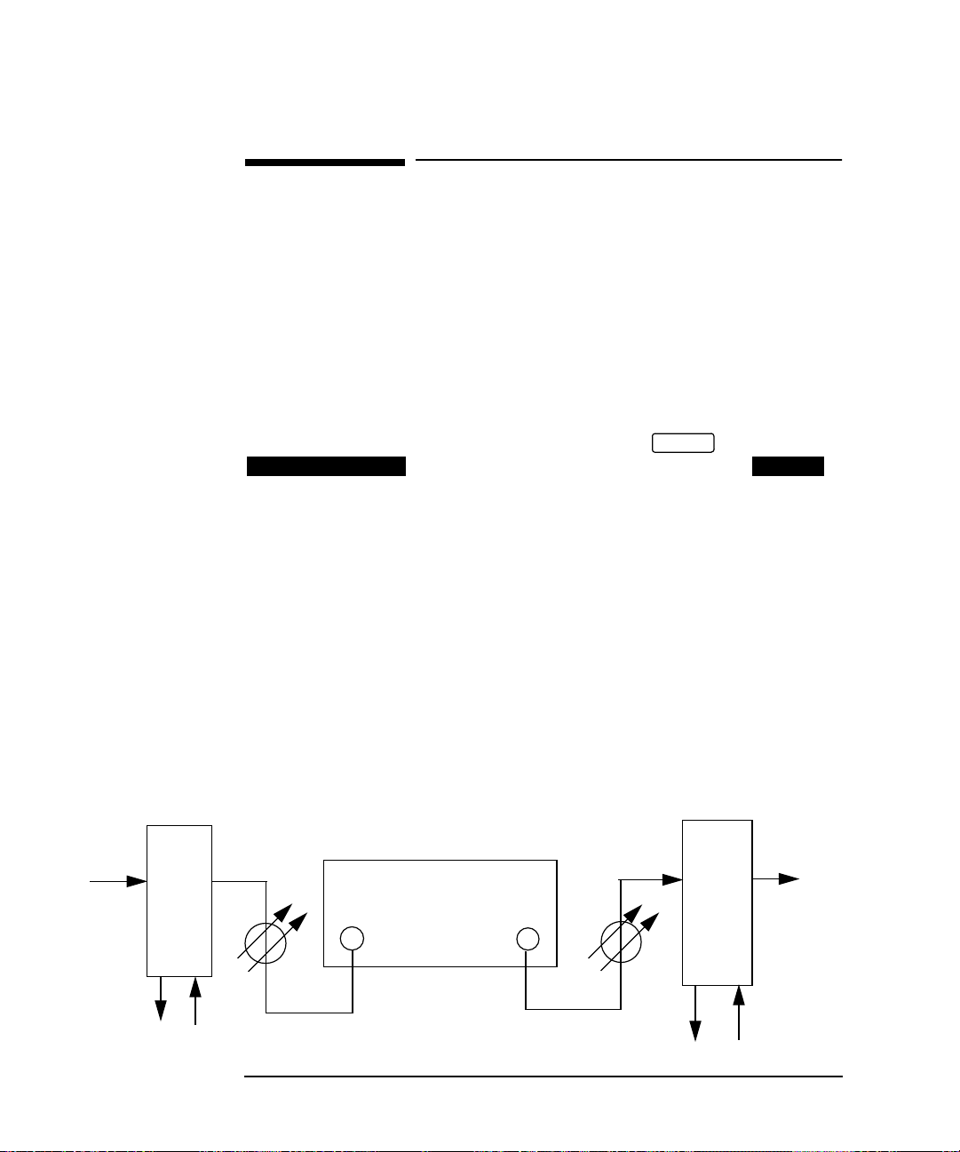
TEST SET
STM1/STM4 STM1/STM4
IN OUT
REGENERATOR
Jitter Transfer Test
Automatic Jitter Transfer Measurement
1. Remove the back to back connection and connect the HP 37717C to the network
equipment as shown above.
NOTE If the measurement is to be made at a network equipment monitor point select
LEVEL [MONITOR] on the display before making the
RECEIVE
SDH JITTER
jitter transfer measurement.
2. Select JITTER,
select MODE and press
RUN/STOP
TRANSMIT
MEASURE
to start the measurement.
SDH
The Jitter Transfer results are plotted in
Graph form and the graph’s progress can
be monitored on the display.
TRANSMIT
33
Page 40

Jitter Testing
Selective Jitter Transfer Measurement
NOTE Changing the HP 37717C configuration or any Jitter Transfer parameter will
invalidate the CALIBRATION. If this occurs the CALIBRATION must be repeated
before a Jitter Transfer measurement is made.
3. The Jitter Transfer results can also be
viewed in TEXT form on the
RESULTS
display.
The following information is displayed for
each result:
Point Number
Jitter Frequency
Mask value
Result
Pass / Fail Indication.
Results 13 to 55 can be viewed on pages 2
through 5.
4. At the end of the measurement the
Graph results and the ITU-T pass mask
can be viewed on the
JITTER
display.
RESULTS
SCALE [WIDE] provides a vertical axis
range of +5 dB to -60 dB and is
recommended for viewing the high
frequency portion of the graph as this
allows a clearer view of the difference
between the actual result and the ITU-T
pass mask.
SCALE [NARROW] provides a vertical axis range of +3 dB to -3 dB and is
recommended for viewing the low frequency portion of the graph as this allows a
clearer view of the difference between the actual result and the ITU-T pass mask.
The graph on the display is cleared when is pressed but
the display remains available.
RESULTS
TRANSMIT TRANSMIT
If the jitter transfer measurement is close to or exceeding the ITU-T pass mask in a
particular area it may be desirable to Zoom in on the area of interest.
This is possible by viewing the TEXT results on the
TRANSFER FUNCTION
display or by using the USER mask capability of the HP
RESULTS
JITTER
37717C.
34
Page 41

Jitter Testing
Selective Jitter Transfer Measurement
To use the USER mask capability select
TRANSMIT
SDH
JITTER and set up
the display as shown opposite.
The user can enter F1, F2, F3, and F4 jitter
frequency points and A1 and A2 jitter
amplitude values.
In this example the jitter transfer will be
measured at 55 points between 50 kHz and
75 kHz, at amplitudes of 0.35 UI, 50 kHz
to 65 kHz and 0.15 UI, 65 kHz to 75 kHz.
NOTE Before the measurement can be made the HP 37717C must be connected back to back
and a calibration performed. Press to start the Calibration.
RUN/STOP
1. Connect the HP 37717C to the network
equipment.
2. Select JITTER,
select MODE and press
RUN/STOP
TRANSMIT
MEASURE
.
SDH
The TEXT and GRAPH results can be
viewed on the
RESULTS
JITTER
display.
SCALE [NARROW] provides a vertical
axis range of +3 dB to -3 dB and is
recommended for viewing the low
frequency portion of the graph as this
allows a clearer view of the difference
between the actual result and the ITU-T
pass mask.
The TEXT results can also be viewed.
35
Page 42

Jitter Testing
In Service ATM Jitter
In Service ATM Jitter
Options required:
• A3K [A3Q] - Jitter Generation
• PDH Module UKJ
• ATM Module UKN
Application
Receiver set to Live Traffic, Jitter added in ATM THRU mode. Swept Mask used
and network equipment checked for Alarms particularly OOF LOF.
Default (Known State) Settings
It can be advisable to set the HP 37717C to a known state prior to setting up to make
a measurement. This clears all previous settings and provides a clearly defined
instrument state. The default settings are set by selecting
SETTINGS RECALL
STORED SETTING NUMBER 0 and pressing .
OTHER
STORED
Test Setup Procedure (In Service SDH Jitter)
In this set up the received ATM signal has Jitter added and is retransmitted via ATM
THRU mode. The Swept Mask feature is used and the HP 37717C "sweeps" through
the jitter mask, adjusting the jitter amplitude according to the jitter frequency. The
network equipment alarms are monitored particularly OOF and LOF.
36
Page 43

Jitter Testing
In Service ATM Jitter
Select PHYSICAL
RECEIVE
ATM
LAYER and set up the display as shown
opposite.
TERMINATION and LINE CODE
selections should match those of the
network equipment.
Select PHYSICAL
TRANSMIT
ATM
LAYER and set up the display as shown
opposite.
Run the Test (In Service ATM Jitter)
Select JITTER and set up
TRANSMIT
the display as shown opposite.
When JITTER MASK [SWEPT] is
selected the HP 37717C will "sweep"
through the jitter mask adjusting
amplitude according to the Jitter
frequency.
Monitor the network alarms
37
Page 44

Jitter Testing
In Service ATM Jitter
38
Page 45

3
3 Result Definitions
.
Page 46

Result Definitions
Jitter Results
Jitter Results
The following Jitter Hits and Jitter Amplitude results are provided. In addition
Wander results are provided at 2 Mb/s.
Table 3-1 Jitter Results
Result Description
+ve PEAK Highest value of positive Jitter during measurement period.
-ve PEAK Highest value of negative Jitter during measurement period.
PEAK-PEAK Highest value of pk_pk Jitter during measurement period.
HIT COUNT Number of times received jitter exceeds a user defined threshold.
HIT SECONDS Number of seconds which contain at least 1 jitter hit.
Table 3-2 Wander Results
Result Description
+ve PEAK Cumulative amount of positive Wander during measurement period.
-ve PEAK Cumulative amount of negative Wander during measurement
PEAK-PEAK Cumulative amount of pk_pk Wander during measurement period.
PEAK-PEAK (15 MIN) Cumulative amount of pk_pk Wander during 15 Minute period.
PEAK-PEAK (24 HOURS) Cumulative amount of pk_pk Wander during 24 Hour period.
TIME INTERVAL ERROR Cumulative
ESTIMATED BIT SLIPS Cumulative count of Bit Slips during measurement Period.
ESTIMATED FRAME SLIPS Cumulative count of Frame Slips during measurement Period.
40
period.
Page 47

4
4 Jitter Logging Messages
.
Page 48

Jitter Logging Messages
Logging Devices
Logging Devices
Results may be logged to the Disc Drive. A bit map of graphics results can be
recorded on the disk drive by using the screen dump feature.
If Remote Control Option A3X is fitted, results may be logged to the Intrenal
Printer.
If Remote Control Option A3B or A3D, is fitted the following types of External
printer can be used for results logging:
• HP-IB HP 550C DeskJet printer
• RS-232-C HP 550C DeskJet printer
• An alternative suppliers RS-232-C printer
The alternative suppliers RS-232-C printer can be 40 column width or 80 column
width. If a 40 column width printer is used Graphics results cannot be logged.
• A Centronics parallel printer
Results Logging
Header and results are logged to the selected device when:
PRINT NOW
• is pressed.
• If LOGGING [ON] is selected on the display and a
measurement is started by pressing
|==============================================================================|
| Hewlett Packard HP37717C |
| Instrument Configuration |
|------------------------------------------------------------------------------|
| RECEIVER |
| Receive Signal : 34 Mb/s Termination : 75 Ohm UNBAL |
| Linecode : HDB3 Payload : FRAMED |
| Payload Type : UNFRAMED |
| Pattern : 2^23-1 Polarity : INVERTED |
| Hit Threshold : 0.70 Filter : OFF |
| Range : 1.6 UI RMS Filter : 12 kHZ HP |
| |
| MEASUREMENT STARTED 23 Jul 97 13:42:49 Print Period 10 Minutes |
|------------------------------------------------------------------------------|
Logging Header
42
OTHER
RUN/STOP
LOGGING
Page 49

Jitter Logging Messages
Results Logging
If is pressed the cumulative results are logged. If a measurement is in
PRINT NOW
progress the current results are logged. If a measurement is not in progress the
cumulative results for the last measurement are logged.
During the Measurement Period
If LOG ERROR SECOND [ON] is selected on the LOGGING display all
occurrences of an Error Second will be logged:
• Bit
• Code (PDH)
• Frame (PDH)
• CRC (PDH)
• REBE (PDH)
• DS3 Frame (SDH)
• DS3 P-Bit (SDH)
• DS3 C-Bit (SDH)
• DS3 FEBE (SDH)
• DS1 Frame (SDH)
• DS1 CRC6 (SDH)
• A1A2 FRAME (SDH)
• RS B1 BIP/B1 BIP (SDH)
• MS B2 BIP/B2 BIP (SDH)
• MS FEBE/RS REI (SDH)
OTHER
• Path B3 BIP/B3 BIP (SDH)
• Path FEBE/HP REI (SDH)
• Path IEC/HP IEC (SDH)
• TU Path BIP (SDH)
• TU Path FEBE/LP REI (SDH)
• Hit Count (Jitter)
• Hit seconds (Jitter)
• Positive Peak Amplitude (Jitter)
43
Page 50

Jitter Logging Messages
Results Logging
• Negative Peak Amplitude (Jitter)
• Peak to Peak Amplitude (Jitter)
• RMS Amplitude (Jitter)
• Positive Peak (2Mb/s Wander)
• Negative Peak (2Mb/s Wander)
• Peak to Peak (2Mb/s Wander)
• Peak to Peak (15 min) (2Mb/s Wander)
• Peak to Peak (24 hours) (2Mb/s Wander)
• Time Interval Error (2Mb/s Wander)
• Estimated Bit Slips (2Mb/s Wander)
• Estimated Frame Slips (2Mb/s Wander)
• EM BIP (ATM)
• FEBE/REI (ATM)
• Corrected HEC (ATM)
• Non Corrected HEC (ATM)
• Cell Loss (ATM)
• Errored Cells (ATM)
• Misinserted Cells (ATM)
All Alarm occurrences will be logged both when set and cleared:
• Signal Loss
• AIS (PDH & ATM)
• Pattern Sync Loss (PDH & ATM)
• Loss Of Frame (SDH, PDH & ATM)
• Out Of Frame (SDH)
• Multiframe (PDH)
• Remote Loss (PDH)
44
Page 51

Jitter Logging Messages
Results Logging
• Remote Multiframe Loss (PDH)
• Loss of Pointer (SDH)
• MS AIS (SDH)
• Path AIS/AU AIS (SDH)
• Pattern Loss (SDH)
• Clock Loss (SDH)
• MS FERF/MS RDI (SDH)
• Path FERF/HP RDI (SDH)
• K1K2 Change (SDH)
• H4 Multiframe Loss (SDH)
• TU Loss of Pointer (SDH)
• TU AIS (SDH)
• TU Path FERF/LP RDI (SDH)
• DS3 Frame Loss (SDH)
• DS3 AIS (SDH)
• DS3 FERF (SDH)
• DS1 Frame Loss (SDH)
• DS1 AIS (SDH)
• DS1 FERF (SDH)
• Jitter Lock Loss (Option UHN[US9])
• Excess Jitter (Option UHN[US9])
• Excess Wander (Option UHN[US9])
• Wander Ref Loss (Option UHN[US9])
• Wander Signal Loss (Option UHN[US9])
• FERF/RDI (ATM)
• Loss of Cell Sync (ATM)
• Selected Cell Not Received (ATM)
• Congestion Experienced (ATM)
45
Page 52

Jitter Logging Messages
Results Logging
• Test Cell Loss (ATM)
• VP AIS (ATM)
• VP FERF/VP RDI (ATM)
• VC AIS (ATM)
• VC FERF/VC RDI (ATM)
In addition the following events are logged:
• All Alarms Clear
• Power Failure
• Power Restored
• New Day
• Squelched - Printing stopped to conserve paper during period of Unavailability
• Unsquelched - Printing restarted after period of Unavailability
• Print Demanded - if is pressed.
• Print Period - if selected on display.
PRINT NOW
OTHER
LOGGING
• Printing Enabled - if Printer enabled during a measurement.
• Measurement Complete
46
Page 53

Jitter Logging Messages
Results Logging
| 10:27:32 LOS SET |
| 10:27:32 LOF SET |
| 10:27:32 OOF SET |
| 10:27:32 AU-LOP SET |
| 10:27:32 Pattern Loss SET |
| 10:27:35 LOS CLEAR |
| 10:27:35 LOF CLEAR |
| 10:27:35 OOF CLEAR |
| 10:27:35 AU-LOP CLEAR |
| 10:27:35 Pattern Loss CLEAR |
| 10:27:35 OOF SET |
| 10:27:35 OOF CLEAR |
| 10:27:35 ALL ALARMS CLEAR |
| 10:27:36 Pattern Loss SET |
| 10:27:36 Pattern Loss CLEAR |
| 10:27:37 ALL ALARMS CLEAR |
| 10:27:41 OOF SET |
| 10:27:41 OOF CLEAR |
| 10:27:42 Pattern Loss SET |
| 10:27:42 Pattern Loss CLEAR |
| 10:27:42 ALL ALARMS CLEAR |
| 10:27:44 OOF SET |
| 10:27:44 OOF CLEAR |
| 10:27:45 Pattern Loss SET |
| 10:27:45 Pattern Loss CLEAR |
| 10:27:46 ALL ALARMS CLEAR |
| 10:28:42 LOS SET |
| 10:28:42 LOF SET |
| 10:28:42 OOF SET |
| 10:28:42 AU-LOP SET |
| 10:28:42 Pattern Loss SET |
| 10:28:44 LOS CLEAR |
| 10:28:44 LOF CLEAR |
| 10:28:44 OOF CLEAR |
| 10:28:44 AU-LOP CLEAR |
| 10:28:44 Pattern Loss CLEAR |
| 10:28:44 OOF SET |
| 10:28:44 OOF CLEAR |
| 10:28:44 ALL ALARMS CLEAR |
| 10:28:45 Pattern Loss SET |
| 10:28:45 Pattern Loss CLEAR |
| 10:28:46 ALL ALARMS CLEAR |
Logging During Measurement Example
47
Page 54

Jitter Logging Messages
Results Logging
At the End of the Measurement Period
A complete set of measurement results are logged.
|==============================================================================|
| MEASUREMENT COMPLETE 23 Jul 97 13:45:17 Elapsed Time 00d 00h 02m 27s|
|==============================================================================|
| Cumulative Results |
| |
| Error Results : |
| FAS 140M FAS 34M FAS 8M FAS 2M |
| Error Count N/A 0 N/A N/A |
| Error Ratio N/A 0 N/A N/A |
| |
| BIT (test) CODE CRC REBE |
| Error Count 0 0 N/A N/A |
| Error Ratio 0 0 N/A N/A |
| |
| JITTER |
| Hit Count 147285 |
| Hit Seconds 56 |
| Hit Free Seconds 91 |
| Positive Peak 0.736 |
| Negative Peak 0.746 |
| Peak-to-Peak 1.482 |
| RMS 0.040 |
| |
| Analysis Results : |
| G.821 ANALYSIS |
| BIT (test) FAS 140M FAS 34M FAS 8M FAS 2M |
| Errored Sec 0 N/A 0 N/A N/A |
| %Errored Sec 0.00000 N/A 0.00000 N/A N/A |
| %ES (Annex D) 0.00000 N/A N/A N/A N/A |
| Error Free Sec 147 N/A 147 N/A N/A |
| %Error Free Sec 100 N/A 100 N/A N/A |
| Severely Err Sec 0 N/A 0 N/A N/A |
| %Severely Err Sec 0.00000 N/A 0.00000 N/A N/A |
| Degraded Minutes 0 N/A 0 N/A N/A |
| %Degraded Minutes 0.00000 N/A 0.00000 N/A N/A |
| Unavailable Sec 0 N/A 0 N/A N/A |
| %Unavailable Sec 0.00000 N/A 0.00000 N/A N/A |
| |
| CODE CRC4 REBE |
| Errored Sec 0 N/A N/A |
| %Errored Sec N/A N/A N/A |
| Error Free Sec N/A N/A N/A |
| %Error Free Sec N/A N/A N/A |
| Severely Err Sec N/A N/A N/A |
| %Severely Err Sec N/A N/A N/A |
| Degraded Minutes N/A N/A N/A |
| %Degraded Minutes N/A N/A N/A |
| Unavailable Sec N/A N/A N/A |
| %Unavailable Sec N/A N/A N/A |
| |
| G.826 ANALYSIS |
| Near 140Mb/s Far Near 34Mb/s Far |
| Errored Seconds N/A N/A 0 0 |
| Severely Errored Seconds N/A N/A 0 0 |
| Unavailable Seconds N/A N/A 0 0 |
| Path Unavailable Seconds N/A N/A 0 0 |
| Errored Second Ratio N/A N/A 0 0 |
| Severely Errored Sec Ratio N/A N/A 0 0 |
| |
48
Page 55

Jitter Logging Messages
Results Logging
| M.2100 ANALYSIS |
| Rx 140Mb/s Tx Rx 34Mb/s Tx |
| Errored Seconds N/A N/A 0 0 |
| Severely Errored Seconds N/A N/A 0 0 |
| Unavailable Seconds N/A N/A 0 0 |
| |
| M.2110 ANALYSIS |
| 2-hr 24-hr 7-day |
| BIS Results WAIT WAIT WAIT |
| |
| M.2120 ANALYSIS |
| TR1 Rx TR1 Tx TR2 Rx TR2 Tx |
| Threshold Reports 0 0 0 0 |
| |
| |
| Frequency : 34368011 Hz Offset : 11 Hz Offset : +0.3 ppm |
|==============================================================================|
Logging At End of Measurement Example
Bar Graph Logging
To log the Bar Graphs:
On the display, LOGGING SETUP , select the
required logging device under LOGGING PORT .
On the CONTROL display, select LOGGING [ON] .
Display the Bar Graphs required on the Bar Graph display and press .
Select .
The Error Summary, the Alarm Summary, the selected Bar Graphs and the Alarms
Graph are logged.
OTHER
OTHER
LOGGING DEVICE
LOGGING
THIS SCREEN
PRINT
49
Page 56

Jitter Logging Messages
Results Logging
Bar Graph Logging Example
Graphics Text Results Logging
To log the Alarm Summaries:
Select the required logging device under LOGGING PORT on the
LOGGING
Select LOGGING [ON] on the display.
display.
OTHER
LOGGING
Display the results required on the Text Results display and press .
The Error Summary and Alarm Summary are logged.
50
OTHER
PRINT
Page 57

Jitter Logging Messages
Results Logging
Results Snapshot Logging
To log the Results Snapshot:
Select the required External logging device under LOGGING PORT on the
OTHER
LOGGING
Select LOGGING [ON] on the display.
display.
OTHER
LOGGING
Select LOG ON DEMAND [RESULTS] on the display
and press .
|==============================================================================|
| Hewlett Packard HP37717C |
| Instrument Configuration |
|------------------------------------------------------------------------------|
| RECEIVER |
| Receive Signal : 34 Mb/s Termination : 75 Ohm UNBAL |
| Linecode : HDB3 Payload : FRAMED |
| Payload Type : UNFRAMED |
| Pattern : 2^23-1 Polarity : INVERTED |
| Hit Threshold : 0.70 Filter : OFF |
| Range : 1.6 UI RMS Filter : 12 kHZ HP |
| |
| MEASUREMENT STARTED 23 Jul 97 13:50:21 Print Period 10 Minutes |
|------------------------------------------------------------------------------|
|==============================================================================|
| 13:52:58 PRINT DEMANDED- RESULTS SNAPSHOT Elapsed Time 00d 00h 02m 36s|
|==============================================================================|
| Cumulative Results |
| |
| Error Results : |
| FAS 140M FAS 34M FAS 8M FAS 2M |
| Error Count N/A 0 N/A N/A |
| Error Ratio N/A 0 N/A N/A |
| |
| BIT (test) CODE CRC REBE |
| Error Count 0 0 N/A N/A |
| Error Ratio 0 0 N/A N/A |
| |
| JITTER |
| Hit Count 32966 |
| Hit Seconds 102 |
| Hit Free Seconds 54 |
| Positive Peak 0.740 |
| Negative Peak 0.746 |
| Peak-to-Peak 1.486 |
| RMS 0.004 |
| |
| Analysis Results : |
| G.821 ANALYSIS |
| BIT (test) FAS 140M FAS 34M FAS 8M FAS 2M |
| Errored Sec 0 N/A 0 N/A N/A |
| %Errored Sec 0.00000 N/A 0.00000 N/A N/A |
| %ES (Annex D) 0.00000 N/A N/A N/A N/A |
| Error Free Sec 156 N/A 156 N/A N/A |
| %Error Free Sec 100 N/A 100 N/A N/A |
| Severely Err Sec 0 N/A 0 N/A N/A |
| %Severely Err Sec 0.00000 N/A 0.00000 N/A N/A |
| Degraded Minutes 0 N/A 0 N/A N/A |
| %Degraded Minutes 0.00000 N/A 0.00000 N/A N/A |
PRINT NOW
OTHER
LOGGING
51
Page 58

Jitter Logging Messages
Results Logging
| Unavailable Sec 0 N/A 0 N/A N/A |
| %Unavailable Sec 0.00000 N/A 0.00000 N/A N/A |
| |
| CODE CRC4 REBE |
| Errored Sec 0 N/A N/A |
| %Errored Sec N/A N/A N/A |
| Error Free Sec N/A N/A N/A |
| %Error Free Sec N/A N/A N/A |
| Severely Err Sec N/A N/A N/A |
| %Severely Err Sec N/A N/A N/A |
| Degraded Minutes N/A N/A N/A |
| %Degraded Minutes N/A N/A N/A |
| Unavailable Sec N/A N/A N/A |
| %Unavailable Sec N/A N/A N/A |
| |
| G.826 ANALYSIS |
| Near 140Mb/s Far Near 34Mb/s Far |
| Errored Seconds N/A N/A 0 0 |
| Severely Errored Seconds N/A N/A 0 0 |
| Unavailable Seconds N/A N/A 0 0 |
| Path Unavailable Seconds N/A N/A 0 0 |
| Errored Second Ratio N/A N/A 0 0 |
| Severely Errored Sec Ratio N/A N/A 0 0 |
| |
| M.2100 ANALYSIS |
| Rx 140Mb/s Tx Rx 34Mb/s Tx |
| Errored Seconds N/A N/A 0 0 |
| Severely Errored Seconds N/A N/A 0 0 |
| Unavailable Seconds N/A N/A 0 0 |
| |
| M.2110 ANALYSIS |
| 2-hr 24-hr 7-day |
| BIS Results WAIT WAIT WAIT |
| |
| M.2120 ANALYSIS |
| TR1 Rx TR1 Tx TR2 Rx TR2 Tx |
| Threshold Reports 0 0 0 0 |
| |
| |
| Frequency : 34368013 Hz Offset : 13 Hz Offset : +0.3 ppm |
|==============================================================================|
Results Snapshot Logging Example
52
Page 59

Jitter Logging Messages
Results Logging
Jitter Auto Tolerance Results Logging
To log the Jitter Auto tolerance plot and results from which the Auto Tolerance plot
is constructed.
On the display, select LOGGING SETUP and
OTHER
LOGGING DEVICE
select the required logging device under LOGGING PORT .
On the display, select LOGGING SETUP and
OTHER
LOGGING CONTROL
set LOGGING [ON] .
On the display:
RESULTS
for PDH Jitter:
select RESULTS ; , select or as
required, and press .
JITTER
PRINT NOW
AUTO TOLER
TEXT GRAPH
for SDH Jitter:
select RESULTS ; , select or as required,
and press .
SDH
PRINT NOW
AUTO TOLER
TEXT GRAPH
53
Page 60

Jitter Logging Messages
Results Logging
Jitter Transfer Logging
To log the Jitter Transfer plot and results from which the Jitter Transfer plot is
constructed.
On the display, select LOGGING SETUP and
OTHER
LOGGING DEVICE
select the required logging device under LOGGING PORT .
On the display, select LOGGING SETUP and
OTHER
LOGGING CONTROL
set LOGGING [ON] .
select RESULTS ; , select or
JITTER
as required, and press .
TRANSFER FUNCTION
PRINT NOW
TEXT GRAPH
54
Page 61

5
5 Jitter Self Test Error Codes
.
Page 62

Jitter Self Test Error Codes
When self test is run fail numbers may be displayed. The fail numbers and a
description are listed below.
Table 5-1 Processor Self Test
No. Description No. Description
1020 SRAM Error 1021 SRAM Error
1022 SRAM Error 1023 SRAM Error
1024 SRAM Adress Error 1040 RS232 DCD
1041 RS232 R1 1042 RS232 DSR
1043 RS232 CTS 1044 RS232 Rx too many bytes
1045 RS232 Tx time out 1046 RS232 Rx too few bytes
1047 RS232 Tx/Rx Data t 1052 HP-IB Driver Chip
1060 Real Time Clock Set Incorrectly 1061 Real Time Clock Not Ticking correctly
1070 Parallel Port No Send Data 1080 Internal Printer
1081 Keyboard Processor Internal RAM 1082 Keyboard Processor External RAM
1083 Keyboard Processor ROM 1084 Front Panel No Response
1085 Front Panel Bad Command 1086 Front Panel Invalid Error Returned
1087 Front Panel CPU or UART 1088 Cannot Detect Front Panel Printer
1090 VRAM Data Error 1100 No Disk in Drive
1101 Disk Full 1102 Disk Write Fail
1103 Disk Read Fail 1104 Disk Verify Read/Write Fail
1110 LAN Failed Power-On Test 1111 LAN Returned Invalid Error Number
1112 LAN Hardware Not Found 1113 Lan Fitted No Test Result
1120 Front Panel No Response 1121 Front Panel Bad Command
1122 Front Panel Returned Invalid Error Number 1123 Dual Port SRAM Data Error
1124 Dual Port SRAM Address Error 1130 Front Panel No Response
1131 Front Panel Bad Command 1132 Front Panel Returned Invalid Error Number
1133 Front Panel FEPROM Sum-check Error 1140 Front Panel No Response
1141 Front Panel Bad Command 1142 Front Panel Returned Invalid Error Number
1143 Front Panel SRAM Data Error 1144 Front Panel SRAM Address Error
1145 Front Panel Address Range Invalid 1150 Front Panel No Response
1151 Front Panel Bad Command 1152 Front Panel Returned Invalid Error Number
1153 Front Panel VRAM Data Error 1154 Front Panel Stored Fonts Corrupted
56
Page 63

Jitter Self Test Error Codes
Table 5-1 Processor Self Test
No. Description No. Description
1155 Front Panel Address Range Invalid 1156 Front Panel VGA Controller Error
1160 Front Panel No Response 1161 Front Panel Bad Command
1162 Front Panel Returned Invalid Error Number 1163 Front Panel UART Tx/Rx Error Internal
1164 Front Panel Internal Loopback not Reset 1166 Front Panel UART Tx/Rx Error External
Table 5-2 JITTER Generator Tests
No. Description No. Description
1411 140 Mb/s PDH, 2 kHz - Errors 1419 140 Mb/s PDH, 2 kHz - VCO not Settling
1421 140 Mb/s PDH, 5 kHz - Errors 1431 34 Mb/s PDH, 2 kHz - Errors
1439 34 Mb/s PDH, 2 kHz - VCO not Settling 1441 34 Mb/s PDH, 5 kHz - Errors
1452 34 Mb/s PDH, 100 kHz - No Errors 1461 8 Mb/s PDH, 2 kHz - Errors
1469 8 Mb/s PDH, 2 kHz - VCO not Settling 1471 8 Mb/s PDH, 5 kHz - Errors
1482 8 Mb/s PDH, 50 kHz - No Errors 1491 2 Mb/s PDH, 2 kHz - Errors
1499 2 Mb/s PDH, 2 kHz - VCO not Settling 14102 2 Mb/s PDH, 5 kHz - No Errors
14111 140 Mb/s SDH, 2 kHz - Errors 14121 140 Mb/s SDH, 5 kHz - Errors
Table 5-3 JITTER Receiver Tests
No. Description No. Description
14133 Intrinsic Jitter 140 Mb/s, PRBS - Result Low 14134 Intrinsic Jitter140 Mb/s, PRBS - Result High
14138 Intrinsic Jitter 140 Mb/s, PRBS - Jitter Unlock 14139 Intrinsic Jitter140 Mb/s - VCO not Settling
14143 Intrinsic Jitter 140 Mb/s, All 0’s - Result Low 14144 Intrinsic Jitter140 Mb/s, All 0’s - Result High
14148 Intrinsic Jitter 140 Mb/s, All 0’s - Jitter Unlock 14153 Intrinsic Jitter140 Mb/s, 1000 - Result Low
14154 Intrinsic Jitter 140 Mb/s, 1000 - Result High 14158 Intrinsic Jitter140 Mb/s, 1000 - Jitter Unlock
14163 Intrinsic Jitter 140 Mb/s, All 1’s - Result Low 14164 Intrinsic Jitter140 Mb/s, All 1’s - Result High
57
Page 64

Jitter Self Test Error Codes
Table 5-3 JITTER Receiver Tests
No. Description No. Description
14168 Intrinsic Jitter 140 Mb/s, All 1’s - Jitter Unlock 14173 Intrinsic Jitter34 Mb/s, PRBS - Result Low
14174 Intrinsic Jitter 34 Mb/s, PRBS - Result High 14178 Intrinsic Jitter 140 Mb/s,PRBS - Jitter Unlock
14179 Intrinsic Jitter 34 Mb/s - VCO not Settling 14183 Intrinsic Jitter 34 Mb/s, All 0’s - Result Low
14184 Intrinsic Jitter 34 Mb/s, All 0’s - Result High 14188 Intrinsic Jitter 34 Mb/s,All 0’s - Jitter Unlock
14193 Intrinsic Jitter 34 Mb/s, 1000 - Result Low 14194 Intrinsic Jitter34 Mb/s, 1000 - Result High
14198 Intrinsic Jitter 34 Mb/s, 1000 - Jitter Unlock 14203 Intrinsic Jitter 34 Mb/s,All 1’s - Result Low
14204 Intrinsic Jitter 34 Mb/s, All 1’s - Result High 14208 Intrinsic Jitter 34 Mb/s,All 1’s - Jitter Unlock
14213 Intrinsic Jitter 8 Mb/s, PRBS - Result Low 14214 Intrinsic Jitter8 Mb/s, PRBS - Result High
14218 Intrinsic Jitter 8 Mb/s, PRBS - Jitter Unlock 14219 Intrinsic Jitter8 Mb/s - VCO not Settling
14223 Intrinsic Jitter 8 Mb/s, All 0’s - Result Low 14224 Intrinsic Jitter8 Mb/s, All 0’s - Result High
14228 Intrinsic Jitter 8 Mb/s, All 0’s - Jitter Unlock 14233 Intrinsic Jitter 8 Mb/s,0001 - Result Low
14234 Intrinsic Jitter 8 Mb/s, 1000 - Result High 14238 Intrinsic Jitter 8 Mb/s,1000 - Jitter Unlock
14243 Intrinsic Jitter 8 Mb/s, All 1’s - Result Low 14244 Intrinsic Jitter8 Mb/s, All 1’s - Result High
14248 Intrinsic Jitter 8 Mb/s, All 1’s - Jitter Unlock 14253 Intrinsic Jitter 2 Mb/s,PRBS - Result Low
14254 Intrinsic Jitter 2 Mb/s, PRBS - Result High 14258 Intrinsic Jitter 2 Mb/s,PRBS - Jitter Unlock
14259 Intrinsic Jitter 8 Mb/s, - VCO not Settling 14263 Intrinsic Jitter 2 Mb/s,All 0’s - Result Low
14264 Intrinsic Jitter 2 Mb/s, All 0’s - Result High 14268 Intrinsic Jitter 2 Mb/s,All 0’s - Jitter Unlock
14273 Intrinsic Jitter 2 Mb/s, 1000 - Result Low 14274 Intrinsic Jitter2 Mb/s, 1000 - Result High
14278 Intrinsic Jitter 2 Mb/s, 1000 - Jitter Unlock 14283 Intrinsic Jitter 2 Mb/s,All 1’s - Result Low
14284 Intrinsic Jitter 2 Mb/s, All 1’s - Result High 14288 Intrinsic Jitter 2 Mb/s,All 1’s - Jitter Unlock
Table 5-4 JITTER Back to Back Tests
No. Description No. Description
14293 140 Mb/s, 0 UI, 10 Hz - Result Low 14294 140 Mb/s, 0 UI, 10 Hz - Result High
14298 140 Mb/s, 0 UI, 10 Hz - Jitter Unlock 14299 140 Mb/s - VCO not Settling
14303 140 Mb/s, 10 UI, 100 Hz - Result Low 14304 140 Mb/s, 10 UI, 100 Hz - Result High
14308 140 Mb/s, 10 UI, 100 Hz - Jitter Unlock 14313 140 Mb/s, 1 UI, 10 kHz - Result Low
14314 140 Mb/s, 1 UI, 10 kHz - Result High 14318 140 Mb/s, 1 UI, 10 kHz - Jitter Unlock
14323 140 Mb/s, 0.6 UI, 3 MHz - Result Low 14324 140 Mb/s, 0.6 UI, 3 MHz - Result High
58
Page 65

Jitter Self Test Error Codes
Table 5-4 JITTER Back to Back Tests
No. Description No. Description
14328 140 Mb/s, 0.6 UI, 3 MHz - Jitter Unlock 14333 34 Mb/s, 0 UI, 10 Hz - Result Low
14334 34 Mb/s, 0 UI, 10 Hz - Result High 14338 34 Mb/s, 0 UI, 10 Hz - Jitter Unlock
14339 34 Mb/s - VCO not Settling 14343 34 Mb/s, 10 UI, 100 Hz - Result Low
14344 34 Mb/s, 10 UI, 100 Hz - Result High 14348 34 Mb/s, 10 UI, 100 Hz - Jitter Unlock
14353 34 Mb/s, 1 UI, 200 kHz - Result Low 14354 34 Mb/s, 1 UI, 200 kHz - Result High
14358 34 Mb/s, 1 UI, 200 kHz - Jitter Unlock 14363 34 Mb/s, 0.6 UI, 500 kHz - Result Low
14364 34 Mb/s, 0.6 UI, 500 kHz - Result High 14368 34 Mb/s, 0.6 UI, 500 kHz - Jitter Unlock
14373 8 Mb/s, 0 UI, 10 Hz - Result Low 14374 8 Mb/s, 0 UI, 10 Hz - Result High
14378 8 Mb/s, 0 UI, 10 Hz - Jitter Unlock 14379 8 Mb/s - VCO not Settling
14383 8 Mb/s, 10 UI, 100 Hz - Result Low 14384 8 Mb/s, 10 UI, 100 Hz - Result High
14388 8 Mb/s, 10 UI, 100 Hz - Jitter Unlock 14393 8 Mb/s, 1 UI, 100 kHz - Result Low
14394 8 Mb/s, 1 UI, 100 kHz - Result High 14398 8 Mb/s, 1 UI, 100 kHz - Jitter Unlock
14403 8 Mb/s, 0.6 UI, 300 kHz - Result Low 14404 8 Mb/s, 0.6 UI, 300 kHz - Result High
14408 8 Mb/s, 0.6 UI, 300 kHz - Jitter Unlock 14413 2 Mb/s, 0 UI, 10 Hz - Result Low
14414 2 Mb/s, 0 UI, 10 Hz - Result High 14418 2 Mb/s, 0 UI, 10 Hz - Jitter Unlock
14419 2 Mb/s - VCO not Settling 14423 2 Mb/s, 10 UI, 100 Hz - Result Low
14424 2 Mb/s, 10 UI, 100 Hz - Result High 14428 2 Mb/s, 10 UI, 100 Hz - Jitter Unlock
14433 2 Mb/s, 1 UI, 25 kHz - Result Low 14434 2 Mb/s, 1 UI, 25 kHz - Result High
14438 2 Mb/s, 1 UI, 25 kHz - Jitter Unlock 14443 2 Mb/s, 0.6 UI, 80 kHz - Result Low
14444 2 Mb/s, 0.6 UI, 80 kHz - Result High 14448 2 Mb/s, 0.6 UI, 80 kHz - Jitter Unlock
Table 5-5 STM-1 Electrical JITTER Receiver Tests
No. Description No. Description
14493 Intrinsic Jitter, Range 1_6, PRBS - Result Low 14494 Intrinsic Jitter,Range 1_6, PRBS - Result High
14496 Intrinsic Jitter Range 1_6, PRBS - Loss of Signal 14498 Intrinsic Jitter Range 1_6, PRBS - Jitter Unlock
14499 Intrinsic Jitter Range 1_6, PRBS - VCO not
Settling
14504 Intrinsic Jitter, Range 1_6, All 0’s - Result High 14506 Intrinsic Jitter, Range 1_6, All 0’s - Loss of Signal
14508 Intrinsic Jitter, Range 1_6, All 0’s - Jitter Unlock 14513 Intrinsic Jitter Range 1_6, All 1’s - Result Low
14503 Intrinsic Jitter Range 1_6, All 0’s - Result Low
59
Page 66

Jitter Self Test Error Codes
Table 5-5 STM-1 Electrical JITTER Receiver Tests
No. Description No. Description
14514 Intrinsic Jitter, Range 1_6, All 1’s - Result High 14516 Intrinsic Jitter, Range 1_6, All 1’s - Loss of Signal
14518 Intrinsic Jitter, Range 1_6, All 1’s - Jitter Unlock 14523 Intrinsic Jitter Range 16, PRBS - Result Low
14524 Intrinsic Jitter, Range 16, PRBS - Result High 14526 Intrinsic Jitter,Range 16, PRBS - Loss of Signal
14528 Intrinsic Jitter, Range 16, PRBS - Jitter Unlock 14533 Intrinsic Jitter Range 16, All 0’s - Result Low
14534 Intrinsic Jitter, Range 16, All 0’s - Result High 14536 Intrinsic Jitter,Range 16, All 0’s - Loss of Signal
14538 Intrinsic Jitter, Range 16, All 0’s - Jitter Unlock 14543 Intrinsic Jitter Range 16, All 1’s - Result Low
14544 Intrinsic Jitter, Range 16, All 1’s - Result High 14546 Intrinsic Jitter, Range 16, All 1’s - Loss of Signal
14548 Intrinsic Jitter, Range 16, All 1’s - Jitter Unlock 14553 Jitter Off - Result Low
14554 Jitter Off - Result High 14556 Jitter Off - Loss of Signal
14558 Jitter Off - Jitter Unlock 14563 Jitter 5 UI, 100 Hz - Result Low
14564 Jitter 5 UI, 100 Hz - Result High 14566 Jitter 5 UI, 100 Hz - Loss of Signal
14568 Jitter 5 UI, 100 Hz - Jitter Unlock 14573 Jitter 5 UI, 1 kHz - Result Low
14574 Jitter 5 UI, 1 kHz - Result High 14576 Jitter 5 UI, 1 kHz - Loss of Signal
14578 Jitter 5 UI, 1 kHz - Jitter Unlock 14583 Jitter 1 UI, 10 kHz - Result Low
14584 Jitter 1 UI, 10 kHz - Result High 14586 Jitter 1 UI, 10 kHz - Loss of Signal
14588 Jitter 1 UI, 10 kHz - Jitter Unlock 14593 Jitter 1 UI, 100 kHz - Result Low
14594 Jitter 1 UI, 100 kHz - Result High 14596 Jitter 1 UI, 100 kHz - Loss of Signal
14598 Jitter 1 UI, 100 kHz - Jitter Unlock 14603 Jitter 0.5 UI, 1 MHz - Result Low
14604 Jitter 0.5 UI, 1 MHz - Result High 14606 Jitter 0.5 UI, 1 MHz - Loss of Signal
14608 Jitter 0.5 UI, 1 MHz - Jitter Unlock 14613 Jitter Hits 1 UI - Result Low
14614 Jitter Hits 1 UI - Result High 14616 Jitter Hits 1 UI - Loss of Signal
14618 Jitter Hits 1 UI - Jitter Unlock
60
Page 67

Jitter Self Test Error Codes
Table 5-6 STM-4 Optical JITTER Receiver Tests
No. Description No. Description
14753 Intrinsic Jitter, Range 1_6, PRBS - Result Low 14754 Intrinsic Jitter,Range 1_6, PRBS - Result High
14757 Intrinsic Jitter Range 1_6, PRBS - Loss of Light 14758 Intrinsic Jitter Range 1_6, PRBS - Jitter Unlock
14763 Intrinsic Jitter Range 1_6, All 0’s - Result Low 14764 Intrinsic Jitter Range 1_6, All 0’s - Result High
14767 Intrinsic Jitter, Range 1_6, All 0’s - Loss of Light 14768 Intrinsic Jitter, Range 1_6, All 0’s - Jitter Unlock
14773 Intrinsic Jitter Range 1_6, All 1’s - Result Low 14774 Intrinsic Jitter, Range 1_6, All 1’s - Result High
14777 Intrinsic Jitter, Range 1_6, All 1’s - Loss of Light 14778 Intrinsic Jitter, Range 1_6, All 1’s - Jitter Unlock
14783 Intrinsic Jitter Range 16, PRBS - Result Low 14784 Intrinsic Jitter, Range 16, PRBS - Result High
14787 Intrinsic Jitter,Range 16, PRBS - Loss of Light 14788 Intrinsic Jitter, Range 16, PRBS - Jitter Unlock
14793 Intrinsic Jitter Range 16, All 0’s - Result Low 14794 Intrinsic Jitter, Range 16, All 0’s - Result High
14797 Intrinsic Jitter,Range 16, All 0’s - Loss of Light 14798 Intrinsic Jitter, Range 16, All 0’s - Jitter Unlock
14803 Intrinsic Jitter Range 16, All 1’s - Result Low 14804 Intrinsic Jitter, Range 16, All 1’s - Result High
14807 Intrinsic Jitter, Range 16, All 1’s - Loss of Light 14808 Intrinsic Jitter, Range 16, All 1’s - Jitter Unlock
14813 Jitter Off - Result Low 14814 Jitter Off - Result High
14817 Jitter Off - Loss of Light 14818 Jitter Off - Jitter Unlock
14823 Jitter 5 UI, 100 Hz - Result Low 14824 Jitter 5 UI, 100 Hz - Result High
14827 Jitter 5 UI, 100 Hz - Loss of Light 14828 Jitter 5 UI, 100 Hz - Jitter Unlock
14833 Jitter 5 UI, 1 kHz - Result Low 14834 Jitter 5 UI, 1 kHz - Result High
14837 Jitter 5 UI, 1 kHz - Loss of Light 14838 Jitter 5 UI, 1 kHz - Jitter Unlock
14843 Jitter 1 UI, 10 kHz - Result Low 14844 Jitter 1 UI, 10 kHz - Result High
14847 Jitter 1 UI, 10 kHz - Loss of Light 14848 Jitter 1 UI, 10 kHz - Jitter Unlock
14853 Jitter 1 UI, 100 kHz - Result Low 14854 Jitter 1 UI, 100 kHz - Result High
14857 Jitter 1 UI, 100 kHz - Loss of Light 14858 Jitter 1 UI, 100 kHz - Jitter Unlock
14863 Jitter 0.5 UI, 1 MHz - Result Low 14864 Jitter 0.5 UI, 1 MHz - Result High
14867 Jitter 0.5 UI, 1 MHz - Loss of Light 14868 Jitter 0.5 UI, 1 MHz - Jitter Unlock
14873 Jitter Hits 1 UI - Result Low 14874 Jitter Hits 1 UI - Result High
14877 Jitter Hits 1 UI - Loss of Light 14878 Jitter Hits 1 UI - Jitter Unlock
61
Page 68

Jitter Self Test Error Codes
Table 5-7 STM-1 Optical JITTER Receiver Tests
No. Description No. Description
14753 Intrinsic Jitter, Range 1_6, PRBS - Result Low 14754 Intrinsic Jitter,Range 1_6, PRBS - Result High
14757 Intrinsic Jitter Range 1_6, PRBS - Loss of Light 14758 Intrinsic Jitter Range 1_6, PRBS - Jitter Unlock
14763 Intrinsic Jitter Range 1_6, All 0’s - Result Low 14764 Intrinsic Jitter Range 1_6, All 0’s - Result High
14767 Intrinsic Jitter, Range 1_6, All 0’s - Loss of Light 14768 Intrinsic Jitter, Range 1_6, All 0’s - Jitter Unlock
14773 Intrinsic Jitter Range 1_6, All 1’s - Result Low 14774 Intrinsic Jitter, Range 1_6, All 1’s - Result High
14777 Intrinsic Jitter, Range 1_6, All 1’s - Loss of Light 14778 Intrinsic Jitter, Range 1_6, All 1’s - Jitter Unlock
14783 Intrinsic Jitter Range 16, PRBS - Result Low 14784 Intrinsic Jitter, Range 16, PRBS - Result High
14787 Intrinsic Jitter,Range 16, PRBS - Loss of Light 14788 Intrinsic Jitter, Range 16, PRBS - Jitter Unlock
14793 Intrinsic Jitter Range 16, All 0’s - Result Low 14794 Intrinsic Jitter, Range 16, All 0’s - Result High
14797 Intrinsic Jitter,Range 16, All 0’s - Loss of Light 14798 Intrinsic Jitter, Range 16, All 0’s - Jitter Unlock
14803 Intrinsic Jitter Range 16, All 1’s - Result Low 14804 Intrinsic Jitter, Range 16, All 1’s - Result High
14807 Intrinsic Jitter, Range 16, All 1’s - Loss of Light 14808 Intrinsic Jitter, Range 16, All 1’s - Jitter Unlock
14813 Jitter Off - Result Low 14814 Jitter Off - Result High
14817 Jitter Off - Loss of Light 14818 Jitter Off - Jitter Unlock
14823 Jitter 5 UI, 100 Hz - Result Low 14824 Jitter 5 UI, 100 Hz - Result High
14827 Jitter 5 UI, 100 Hz - Loss of Light 14828 Jitter 5 UI, 100 Hz - Jitter Unlock
14833 Jitter 5 UI, 1 kHz - Result Low 14834 Jitter 5 UI, 1 kHz - Result High
14837 Jitter 5 UI, 1 kHz - Loss of Light 14838 Jitter 5 UI, 1 kHz - Jitter Unlock
14843 Jitter 1 UI, 10 kHz - Result Low 14844 Jitter 1 UI, 10 kHz - Result High
14847 Jitter 1 UI, 10 kHz - Loss of Light 14848 Jitter 1 UI, 10 kHz - Jitter Unlock
14853 Jitter 1 UI, 100 kHz - Result Low 14854 Jitter 1 UI, 100 kHz - Result High
14857 Jitter 1 UI, 100 kHz - Loss of Light 14858 Jitter 1 UI, 100 kHz - Jitter Unlock
14863 Jitter 0.5 UI, 1 MHz - Result Low 14864 Jitter 0.5 UI, 1 MHz - Result High
14867 Jitter 0.5 UI, 1 MHz - Loss of Light 14868 Jitter 0.5 UI, 1 MHz - Jitter Unlock
14873 Jitter Hits 1 UI - Result Low 14874 Jitter Hits 1 UI - Result High
14877 Jitter Hits 1 UI - Loss of Light 14878 Jitter Hits 1 UI - Jitter Unlock
62
Page 69

Jitter Self Test Error Codes
Table 5-8 RMS JitterTests (Options A3L, A3V, A3N)
No. Description No. Description
14145 140 Mb/s, All 0’s - Result Low 14146 140 Mb/s, All 0’s - Result High
14185 34 Mb/s, All 1’s - Result Low 14186 34 Mb/s, All 1’s - Result High
14225 8 Mb/s, All 1’s - Result Low 14226 8 Mb/s, All 1’s - Result High
14265 2 Mb/s, All 1’s - Result Low 14266 2 Mb/s, All 1’s - Result High
14315 140 Mb/s, 1 UI, 10 kHz - Result Low 14316 140 Mb/s, 1 UI, 10 kHz - Result High
14355 34 Mb/s, 1 UI, 200 kHz - Result Low 14356 34 Mb/s, 1 UI, 200 kHz - Result High
14395 8 Mb/s, 1 UI, 100 kHz - Result Low 14396 8 Mb/s, 1 UI, 100 kHz - Result High
14435 2 Mb/s, 1 UI, 25 kHz - Result Low 14436 2 Mb/s, 1 UI, 25 kHz - Result High
14495 STM-1 E, PRBS23 - Result Low 14496 STM-1 E, PRBS23 - Result High
14595 STM-1 E, 1 UI, 10 kHz - Result Low 14596 STM-1 E, 1 UI, 10 kHz - Result High
14625 STM-1 Opt, All 1’s - Result Low 14626 STM-1 Opt, All 1’s - Result High
14725 STM-1 Opt, 1 UI, 10 kHz - Result Low 14726 STM-1 Opt, 1 UI, 10 kHz - Result High
14755 STM-4, All 0’s - Result Low 14756 STM-4, All 0’s - Result High
14855 STM-4,1 UI, 10 kHz - Result Low 14856 STM-4,1 UI, 10 kHz - Result High
63
Page 70

Jitter Self Test Error Codes
Table 5-9 JITTER Back to Back Tests (Opt A3K)
No. Description No. Description
14881 2 Mb/s, 80 UI, 100 Hz - Errors 14889 2 Mb/s, 80 UI, 100 Hz - VCXO not Settling
14893 2 Mb/s, 13 UI, 100 Hz - Result Low 14894 2 Mb/s, 13 UI, 100 Hz - Result High
14898 2 Mb/s, 13 UI, 100 Hz - Jitter Unlock 14899 2 Mb/s, 13 UI, 100 Hz - VCXO not Settling
14902 2 Mb/s, 20 UI, 100 Hz - Overrange not Detected 14908 2 Mb/s, 20 UI, 100 Hz - Jitter Unlock
14909 2 Mb/s, 20 UI, 100 Hz - VCXO not Settling 14911 140 Mb/s, 50 UI, 100 Hz - Errors
14923 STM-1E, 13 UI, 100 Hz - Result Low 14924 STM-1E, 13 UI, 100 Hz - Result High
14928 STM-1E, 13 UI, 100 Hz - Jitter Unlock 14929 STM-1E, 13 UI, 100 Hz - VCXO not Settling
14933 STM-1O, 13 UI, 100 Hz - Result Low 14934 STM-1O, 13 UI, 100 Hz - Result High
14938 STM-1O, 13 UI, 100 Hz - Jitter Unlock 14939 STM-1O, 13 UI, 100 Hz - VCXO not Settling
14943 STM-4, 12 UI, 100 Hz - Result Low 14944 STM-4, 12 UI, 100 Hz - Result High
14948 STM-4, 12 UI, 100 Hz - Jitter Unlock 14949 STM-4, 12 UI, 100 Hz - VCXO not Settling
64
Page 71

Index
A
Automatic Jitter Transfer, 5
B
Bar Graph Logging, 49
Bit error threshold, 6
D
Delay Time, 32
Delay time, 6
Desynchroniser Stress, 18
Dwell Time, 6
G
Graphics
Bar Graph Logging, 50
Logging Bar Graphs, 49
I
In Service ATM Jitter, 36
In Service SDH Jitter, 24
J
Jitter & Wander Generator, 6
Jitter and Wander Generation, 6
Jitter Auto Tolerance Logging, 53
Jitter Introduction, 2
Jitter Measurement
PDH & STM-1, 4
PDH & STM-1E, 3
PDH, STM-1 & STM-4, 5
Jitter Tolerance Test
SPDH, 9
Unstructured PDH, 9
Jitter Transfer Logging, 54
Jitter Transfer Measurement, 29
L
Logging At End of Measuremen, 49
Logging Bar Graphs, 50
Logging Devices, 42
Logging During Measurement, 47
Logging Header, 42
Logging Messages, ??–12, ??–12, ??–53,
??–53, ??–54
Logging Results
At end of Measurement, 48
Bar Graphs, 48
During Measurement, 43
Error & Alarm Summaries, 50
Graphics Text, 50
Jitter Auto Tolerance, 53
Jitter Autotolerance, 53
Jitter Transfer, 54
Logging Header, 42
Result Snapshot, 51
M
Multiplexer Jitter Tolerance, 8
O
Option A3K, 6
P
PDH, 3
PDH Tests, Option UKK (75W Unbal
Back to Back), 56
Q
Q Factor, 6
R
Results Definitions
Jitter, 40
Wander, 40
Results Snapshot Logging Example, 52
S
SDH Jitter Tolerance, 21
Selective Jitter Transfer Measurement, 29
Slips and Wander, 13
Stored Text Results Logging, 51
T
Text Results Logging, 51
Tributary Mapping Jitter, 26
Tributary Mapping Jitter Test, 27
W
Wander and Slips, 13
Wander and Slips Test, 14
Wander Generator, 6
Wander modulation, 6
Wander Results, 40
65
Page 72

Index
66
Page 73

Hewlett-Packard Sales and Service Offices
Hewlett-Packard Sales and Service Offices
United States:
Hewlett-Packard Company
2101 Gaither Road
Rockville
MD 20850
(301) 258-2000
Hewlett-Packard Company
5201 Tollview Drive
Rolling Meadows
IL 60008
(708) 255-9800
Hewlett-Packard Company
1421 S. Manhattan Avenue
Fullerton
CA 92631
(714) 999-6700
Hewlett-Packard Company
2000 South Park Place
Atlanta
GA 30339
(404) 955-1500
Japan:
Yokogawa-Hewlett-Packard Ltd.
Measurement Assistance Center
9-1, Takakura-Cho
Hachioji-Shi
Tokyo 192
Japan
(81) 426 48 0722
Latin America:
Hewlett-Packard
Latin America Region Headquarters
5200 Blue Lagoon Drive
9th Floor
Miami
Florida 33126
USA
(305) 267 4245/4220
Australia/New Zealand:
Canada:
Hewlett-Packard Canada Ltd.
5150 Spectrum Way
Mississauga
Ontario
L4W 5G1
(416) 206-4725
Europe:
Hewlett-Packard
European Marketing Centre
PO Box 999
1180 AZ Amstelveen
The Netherlands
Hewlett-Packard Australia Ltd.
31-41 Joseph Street
Blackburn
Victoria 3130
Australia
Melbourne Caller 272 2555
(008) 13 1347
Far East:
Hewlett-Packard Pacific Ltd.
22-30/F Peregrine Tower
Lippo Centre
89 Queensway
Central
Hong Kong
(852) 848 7070
Page 74

Learning Products Map
:All of the learning products which apply to the HP 37717C Communications Performance Analyzerare shown
below:
Quick Start Guide - 37717-90255
The Quick Start Guide demonmstrates the basic methods of instrument operation. This guide tells you how to
select the displays that you want and how to use them to modify the instrument functions. This guide also tells
you about the front panel key functions, the indicators and the connectors.
Users Manual - 37717-90256
The Users Manual tells you how to make the selections you want to set up the instrument.
Concept Guides
The concept guides provide descriptions of the instrument features, default settings, application ideas, result
definitions, logging messages and self test fail codes.
The concept guides supplied are:
PDH Concept Guide- 37717-90257
SDH Concept Guide - 37717-90252
Jitter Concept Guide - 37717-90258
ATM Concept Guide - 37717-90259
Remote Control Manual - 37717-90290:
Provides remote control information for instruments fitted with the RS232 and HP-IB remote control option
modules.
Calibration Manual - 37717-90289:
Provides specifications and methods of testing that the instrument meets its specifications.
Page 75

About This Edition
This is the 1st edition of
the 37717-90258 manual.
It documents the product
as of July 1997. Edition
dates are as follows:
1st Edition, July 1997
Copyright Hewlett-
Packard Ltd. 1997.
All rights reserved.
Reproduction, adaption,
or translation without prior
written permission is
prohibited, except as
allowed under the
copyright laws.
Page 76

In This Book
This book provides information on HP 37717C
modules with Jitter capability. It also provides
applications associated with these modules.
The individual applications contain techniques
which may be of value for purposes other than
those shown
Printed in U.K. 07/97
37717-90258
Page 77

Double-click here to define book introduction head
drawings/a1m.tif @ 150 dpi 3
drawings/a1pa.tif @ 150 dpi 4
drawings/a1pa.tif @ 150 dpi 5
drawings/a3k.tif @ 300 dpi 6
drawings/sjittol.tif @ 300 dpi 9
drawings/jittol.tif @ 300 dpi 9
drawings/p17mm14a.tif @ 300 dpi 10
drawings/jitt24.tif @ 300 dpi 10
drawings/p17mm11a.tif @ 300 dpi 10
drawings/p17mm15a.tif @ 300 dpi 11
drawings/p14mm67.tif @ 150 dpi 11
drawings/p14mm68.tif @ 300 dpi 11
drawings/p14mm68po.tif @ 150 dpi 11
drawings/wander.tif @ 300 dpi 14
drawings/jit80.tif @ 300 dpi 14
drawings/p14mm57a.tif @ 300 dpi 14
drawings/jit81.tif @ 300 dpi 15
drawings/wan1.tif @ 300 dpi 15
drawings/p14mm61.tif @ 300 dpi 16
drawings/p14mm61po.tif @ 150 dpi 16
drawings/desync.tif @ 300 dpi 19
drawings/p17mm66.tif @ 300 dpi 19
drawings/p17mm67.tif @ 300 dpi 19
drawings/p17mm68.tif @ 300 dpi 20
drawings/jitt28.tif @ 300 dpi 20
drawings/p17mm69.tif @ 300 dpi 20
drawings/jitt11.tif @ 300 dpi 22
drawings/jitt12.tif @ 300 dpi 22
drawings/jitt13a.tif @ 300 dpi 23
drawings/jitt21.tif @ 150 dpi 23
drawings/jitt22.tif @ 300 dpi 23
drawings/jitt22po.tif 23
DRAFT 71
Page 78

Double-click here to define book introduction head
drawings/jitt14.tif @ 300 dpi 25
drawings/jitt15.tif @ 300 dpi 25
drawings/jitt16.tif @ 300 dpi 25
drawings/jitt81.tif @ 300 dpi 26
drawings/jitt17.tif @ 300 dpi 28
drawings/jitt18.tif @ 300 dpi 28
drawings/jitt19.tif @ 300 dpi 28
drawings/sdh50.tif @ 300 dpi 31
drawings/jit71.tif @ 300 dpi 31
../../../hpsqfch/37717b/frame/JITTMOD/jitt72.tif @ 150 dpi 31
drawings/jit73.tif @ 300 dpi 31
drawings/jit61.tif @ 300 dpi 32
drawings/jitt76.tif @ 150 dpi 32
drawings/jit65.tif 33
drawings/jit68po.xwd 33
drawings/calmeas.xwd 33
drawings/jit70.tif @ 300 dpi 34
drawings/jit70po.xwd @ 300 dpi 34
drawings/jit69.tif @ 300 dpi 34
drawings/jit69po.xwd 34
drawings/jit77.tif @ 300 dpi 35
drawings/jit78.tif @ 300 dpi 35
drawings/jit78po.xwd 35
drawings/calmeas.xwd 35
drawings/jit79.tif @ 300 dpi 35
drawings/jit79po.xwd @ 300 dpi 35
drawings/jitt20.tif @ 300 dpi 37
drawings/jitt23.tif @ 300 dpi 37
drawings/jitt25.tif @ 300 dpi 37
drawings/gen41.tif @ 150 dpi 50
drawings/bc90258.tif @ 132 dpi 70
72 DRAFT
 Loading...