

Page 1

HP
OmniBER 717
Communications Performance Analyzer
New dual
SONET/SDH
and DS1/DS3
capability
Product specifications
and characteristics
specification
SONET (STS-1, STS-3, OC-1, OC-3, OC-12)
SDH (STM-0, STM-1, STM-4, STM-4c)
PDH (704 kb/s, 2/8/34/140 Mb/s)
DSn (DS1, DS3)
ATM (1.5/2/34/45/140 Mb/s, STM-1, OC-3)
Jitter (2/8/34/140/155/622 Mb/s)
Binary (700 kb/s to 170 Mb/s)
Page 2

About this documentAbout this document
About this document
About this documentAbout this document
This technical specification provides
contents
detailed product specifications and
characteristics appropriate to and covering
the HP OmniBER 717 and its options.
Options quick reference
Contents
Introduction ............................................................................................... 3
Features ...................................................................................................... 5
Capability summary ............................................................................... 12
Specifications ......................................................................................... 14
PDH and DS1/DS3 options .................................................................... 14
PDH ................................................................................................... 14
DS1/DS3/E1/E3 structured test and interfacing............................ 18
UKK ........................ Page 14
UKJ ................................... 14
UKN.............................14, 53
110 ....................................18
A3R ................................... 22
UH1 .............................29, 67
130 ....................................30
131 ....................................30
120 ....................................34
A3K ................................... 40
140 ....................................40
UHN .................................. 45
A3L .................................... 45
A3V ................................... 45
A3N ................................... 45
UKZ ................................... 56
0YK ................................... 60
USL ................................... 60
A1T ................................... 63
USN................................... 68
UKT ................................... 68
0YH ................................... 72
UH3 ...................................73
UHC ................................... 76
SDH test and interfacing options ........................................................ 22
STM-0/STM-1e test and interfacing .............................................. 22
STM-1 optical interfacing ............................................................... 29
STM-4c, STM-4, STM-1 and STM-0 test
and optical interfacing .................................................................... 30
Dual standard SONET/SDH test and
interfacing options................................................................................. 34
Dual standard SONET/SDH test and interfacing ........................... 34
Jitter generation and measurement options .................................... 40
Jitter generation .............................................................................. 40
Jitter measurement ......................................................................... 45
ATM test and interfacing ...................................................................... 53
ATM cell test options (ETSI only) .................................................... 53
ATM cell test options (ITU-T/ANSI) ................................................ 56
ATM services test options............................................................... 61
STM-1e ATM test and interfacing .................................................. 63
STM-1 optical interfacing ............................................................... 67
STM-4 and STM-1 test and optical interfacing ............................. 68
Binary interfacing and multiple output options .............................. 72
STM-4, STM-1 and STM-0 binary interfaces ................................. 72
PDH binary interfaces ...................................................................... 73
Multiple PDH outputs ...................................................................... 76
General specifications.......................................................................... 77
Disk drive .......................................................................................... 77
Graphics/logging ............................................................................. 77
Printers ............................................................................................. 78
Remote control/printer interface options ...................................... 78
Distributed/remote testing ............................................................. 78
General ............................................................................................. 79
Accessories ...................................................................................... 79
Distributed network analyzer (DNA) .................................................. 80
2
Page 3
Introduction
introduction
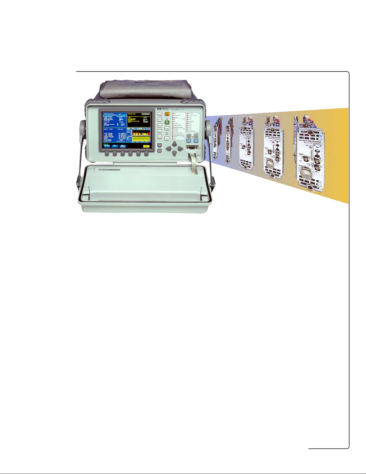
The HP OmniBER 717 is a
modular, portable analyzer
that supports optical and
electrical interfaces for TCarrier, PDH, SONET, SDH,
ATM, jitter and LAN
applications from 704 kb/s to
622 Mb/s (OC-12/STM-4).
The HP OmniBER 717 has an
easy-to-read color display. It
offers an extensive range of
T-carrier, PDH, SONET, SDH,
ATM, jitter and LAN
measurements.
Each analyzer provides
dedicated slots for an optical
interface and the printer/
remote-control module, plus
up to eight slots for other
interface and measurement
modules. This provides the
analyzer with the flexibility to
offer dedicated modules for
T-Carrier, PDH, SONET/SDH,
SDH only, ATM, and jitter
which can be combined
together in the one mainframe
enabling a range of test
requirements to be covered.
The test and interface modules
offer a range of measurements
including detailed overhead,
parity and alarm testing as well
as frequency offset tolerance
tests, frequency measurement
and optical power
measurement. The analyzers
also offer enhanced test
features like pointer sequence
generation, overhead access
and manipulation, overhead
sequence generation and
capture, service disruption
measurement, plus thru mode
capability. The structured
T-carrier and PDH modules
also offer ITU-T M.2100/
M.2101/M.2110/M.2120 testing
with comprehensive ITU-T
G.821 and G.826 in-service and
out-of-service analysis.
Dedicated test hardware
provides all results and
analysis simultaneously, so all
relevant measurements are
made in one test run saving
time and hence money.
For transmit and receive
testing of short-, intermediateand long-reach optical circuits,
there is a choice of 1310 and/
or 1550 nm OC-1/STM-0, OC-3/
STM-1 and OC-12/STM-4
optical modules. Electrical
interfaces at STS-1/STM-0 and
STS-3/STM-1 are also
available, as are jitter
generation and measurement
interfacing options.
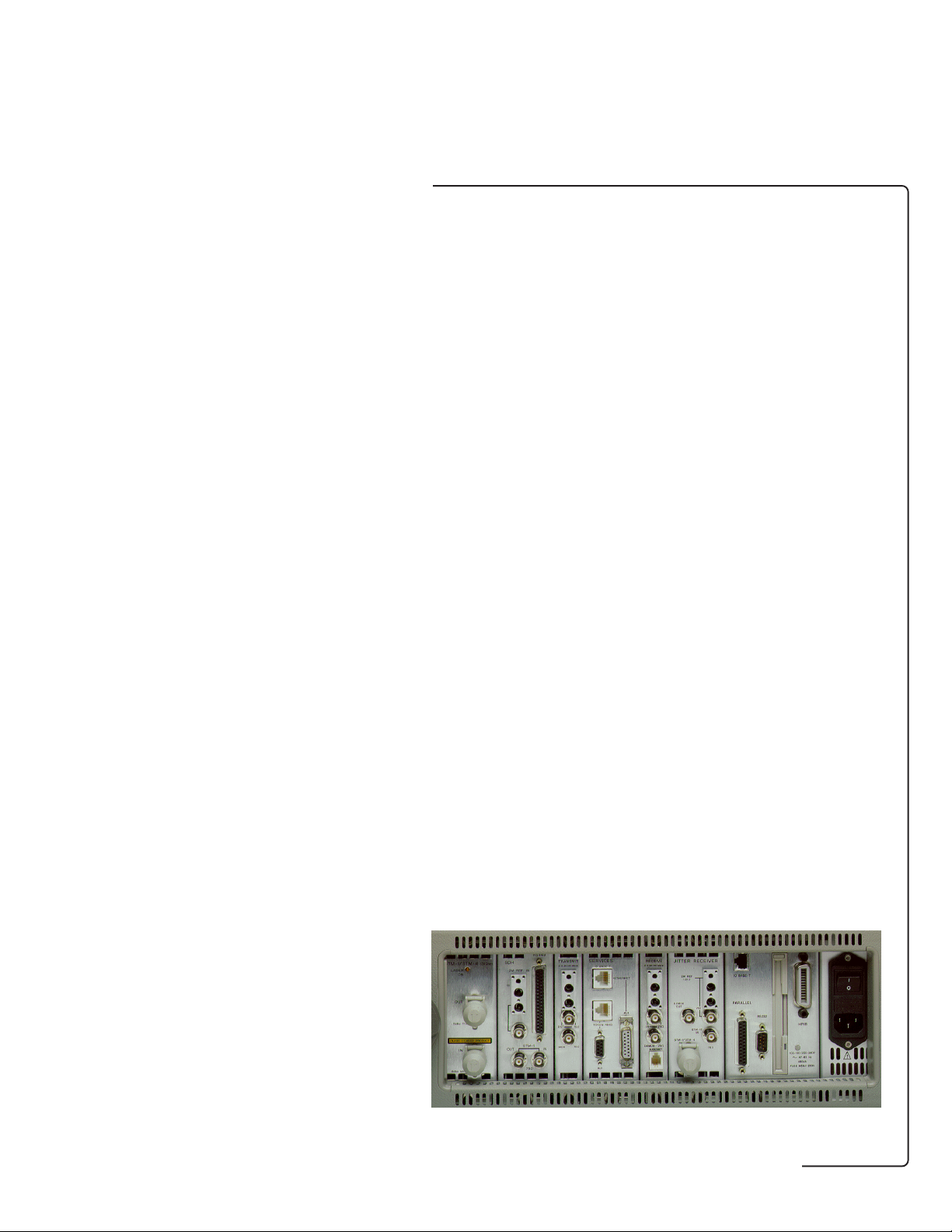
Side view of the HP OmniBER 717
communications performance analyzer
3
Page 4
features
introduction
HP OmniBER 717 analyzer with
color display and optional in-lid
graphics printer
Test/interface/periheral modules supported include:
● STS-1, STS-3/STS-3c, OC-1, OC-3/OC-3c, OC-12/OC-12c
measurements
● OC-1, OC-3/OC-3c, OC-12/OC-12c optical (1310/1550 nm) and
NRZ interfaces
● STM-0, STM-1, STM-4/STM-4c measurements
● STM-0, STM-1, STM-4/STM-4c optical (1310/1550 nm) and
NRZ interfaces
● Structured PDH interfaces at 2/8/34/140 Mb/s
● Structured T-carrier/ETSI interfaces at DS1/DS3/E1/E3
● ATM services layer testing with/without native LAN
connectivity
● ATM cell layer generation and measurement for ANSI/ETSI
standards(DS1/DS3/E1/E3/OC-3c/STM-1)
● External printer/remote-control interfaces
● In-lid 80 column graphics printer (including screen dump
facility).
4
Page 5

Features
The HP OmniBER 717 offers
features
powerful, dedicated features
that simplify the assessment of
networks.
This section covers features as
follows:
● General
● Optional PDH
● Optional DS1/DS3
● Optional SDH
● Optional SONET
● Optional ATM cell layer
● Optional ATM services
● Optional jitter
General
Status indicators
HP OmniBER 717:
Stored measurement
graphics
View results graphically.
Event-based time and date
stamped measurement results
are stored by the instrument
with a 1 second resolution. A
text summary of the results is
also available. Graphics
displays may be logged to a
printer.
Parametric testing
Optical power measurement
(requires optical interface
options 130/131 or USN/UKT)
Screen dump
Full-width printing of
instrument screen to
HP OmniBER 717 analyzer's
graphics printer at press of a
key.
‘Trouble Scan’ mode
Use ‘Trouble Scan’ mode to
scan for alarms and to display
non-zero error counts in extra
large characters.
Avoid the need to carry
additional optical power
meters!
5
Page 6
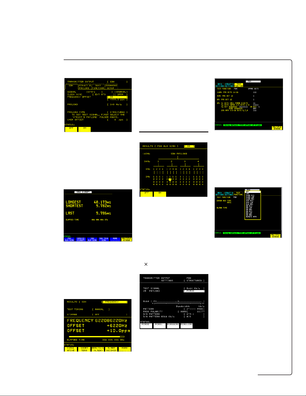
Frequency offset
features
Measure the clock frequency
and the amount of offset from
the Bellcore/ITU-T standard
rate. Out-of-service or inservice frequency measurement can be made at all the
interface rates.
PDH/DSn features
Spare bits access
Test the capability of network
equipment to reliably recover
the clock by varying the clock
rate of the generated data and
checking for the occurrence of
transmission errors.
Protection switch times
Test protection switching
mechanisms to ITU-T G.783,
G.841 or Bellcore GR-253
limits using the service
disruption test.
‘Alarm Scan’ mode
Automatically scan the PDH/
DSn network hierarchy carried
within an SDH/SONET signal
structure for alarms with the
press of a key. ‘Alarm Scan’
mode shows the alarm state of
all alarms in a structured
signal.
N ´ 64 kb/s
Modify the spare bits at 2,
8, 34 and 140 Mb/s interface
rates. Modify and access the
ABCD signaling bits. (CAS
multiframe mode).
Alarm generation
Check your PDH/DSn network
elements and tributary insert
ports using the PDH/DSn alarm
generation facility.
Frequency measurement
Readily check 64 kb/s or
N × 64 kb/s digital paths (to
ITU-T G.704: 1 to 31
contiguous and non-contiguous
timeslots).
6
Page 7
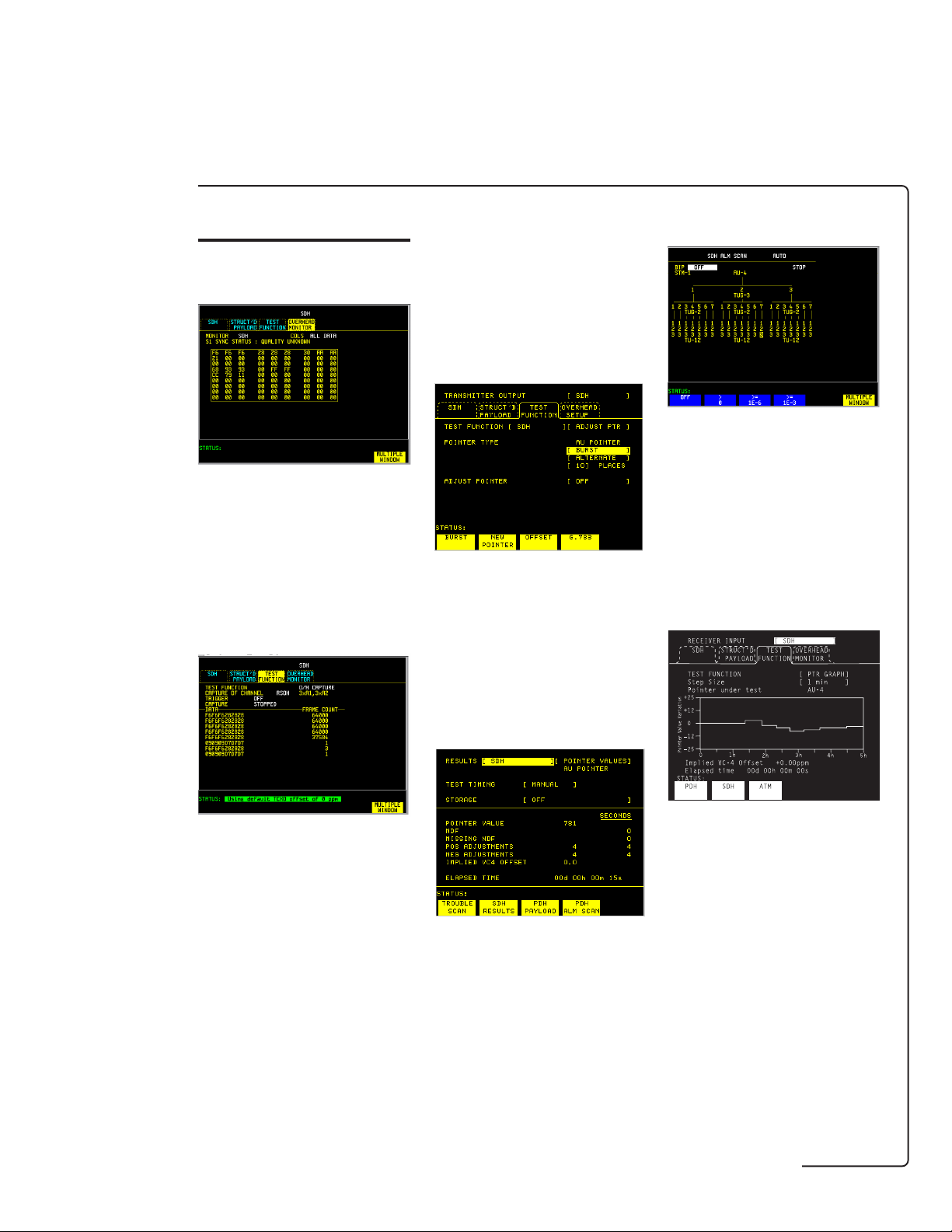
SDH features
features
Overhead access
View the section and path
overhead bytes of a received
SDH signal. Bit by bit access of
transmitted section and path
overhead bytes. Display in hex
or binary.
Overhead sequences
DCC drop and insert
Drop or insert RSOH and
MSOH DCC channels via the
SDH module's RS-449
connector.
Pointer adjustments and
analysis
Make positive and negative
adjustments with added and
canceled pointers as per
ITU-T G.783 plus 87:3 pointer
test sequence, then view the
AU and TU pointer value and
AU and TU positive and
negative adjustments.
SDH alarm scan
In-service SDH alarm and BIP
scan automatically scans all
TU-n tributaries within a
received STM-n signal allowing
fast sectionalization of faults.
Auto scan facilities
automatically determines the
received signal structure.
Pointer location graph
Overwrite static values in a
single overhead channel with a
single or repeated sequence of
user-defined values. Detect
intermittents by capturing
selected section and path
overhead channels.
Overhead BER
measurement
Perform a BER measurement
on a selected section or path
channel. Error count, error
ratio, error free seconds and %
error free seconds are
displayed.
Determine the synchronization
status of your network by
monitoring the received AU/TU
pointer value over time. Check
for wander problems or
excessive pointer movements.
PDH drop and insert
Drop/insert of 34/140/2 Mb/s to
or from an STM-1/STM-4
signal.
Thru mode
Use the STM-0/STM-1/STM-4
thru mode for in-service
monitoring where no protected
monitor points are available.
7
Page 8

Mixed payloads
features
Generate mixed TU-3 and TU12 signal structures in order to
test network elements,
configured to carry mixed 2
Mb/s and 34 Mb/s traffic.
SDH tributary scan
Automatic verification of VC-n
paths within an ADM etc, using
the out-of-service tributary
scan for faster installation
testing.
SONET features
Overhead access
View the transport and path
overhead bytes of a received
SONET signal. Bit by bit access
of transmitted section and path
overhead bytes. Display in hex
or binary.
Overhead sequences
Overwrite static values in a
single overhead channel with a
single or repeated sequence of
user-defined values. Detect
intermittents by capturing
selected section and path
overhead channels.
Overhead BER
measurement
Perform a BER measurement
on a selected section, line or
path channel. Error count,
error ratio, error free seconds
and % error free seconds are
displayed.
DCC drop and insert
Drop or insert TOH and TOH
DCC channels via the SONET/
SDH module's RS-449
connector.
Pointer adjustments and
analysis
Make positive and negative
adjustments with added and
canceled pointers as per
ANSI T1.105.03 plus 87:3
pointer test sequence, then
view the SPE and VT pointer
value and SPE and VT positive
and negative adjustments.
SONET alarm scan
In-service SONET alarm and
BIP scan automatically scans
all VTn tributaries within a
received OC-n/STS-n signal
allowing fast sectionalization of
faults. Auto scan facilities
automatically determines the
received signal structure.
8
Page 9

Pointer location graph
features
Determine the synchronization
status of your network by
monitoring the received SPE/
VT pointer value over time.
Check for wander problems or
excessive pointer movements.
DSn/PDH drop and insert
Drop/insert of DS1/DS3/2M to
or from an OC-3/OC-12 signal.
ATM features
Change cell stream bandwidth
to obtain quickly quality-ofservice data for the ATM
network.
A single ATM virtual channel
(VC) is set up as the
foreground test signal. The
remaining bandwidth is then
filled with background VCs and
idle or unassigned cells.
Cell delay
Thru mode
Use the OC-1/OC-3/OC/12 thru
mode for in-service monitoring
where no protected monitor
points are available.
Mixed payloads
Generate mixed STS-1 signal
structures within STS-3/OC-3
signal structures in order to
test network elements.
SONET tributary scan
Set cell content to ITU-T O.191
test cells for cell performance
measurements (eg, cell loss,
delay, misinsertion or errors),
PRBS or user defined pattern.
Channel View
Find and identify the VPI/VCI
of up to 1023 channels,
showing cell rates or
percentage for all found VCs;
VPI display filter, AAL type and
ATM alarms displayed against
each VC.
Graphical display for 1-point
and 2-point cell delay variation
(ITU-T I.356) and nonconforming cell count.
AAL monitoring
(AAL-1, AAL-3/4, AAL-5)
SAR-PDU counts/rate, CRC
errors, sequence errors, lost
cell count, aborted PDUs and
length errors.
Automatic verification of VTn
paths within an ADM etc, using
the out-of-service tributary
scan for faster installation
testing.
9
Page 10

VC rate history
features
Graphical display of maximum,
mean and minimum cell rate on
a chosen VC for short or
extended periods (up to a
month).
Native LAN
Ethernet LAN interfaces; 'ping'
tests for lost packet counts;
round trip delay under
different load conditions.
Verification of file transfer and
transfer time.
Jitter features
Jitter tolerance
Use the automatic jitter
tolerance test to verify
network equipment's
performance margins relative
to ITU-T G.823 (PDH) and
G.958 (SDH) jitter masks.
Jitter transfer
Wander measurement
View current measurements in
graphical or text format on the
results display. Three +ve and
−ve sliding graphs, each
showing ± 1 UI, ± 16 UI and ±
256 UI are provided.
After installing a native LAN
over WAN service and before
handing over to the customer,
you'll want to be certain that
the service performs properly.
Using the provided IP protocol,
you can readily check latency
(delay) and connectivity in
such installations.
Jitter sweep
Automatic jitter transfer test
(with narrow bandwidth
selective filtering) tests jitter
accumulation in regenerative
repeators etc.
Sweep the ITU-T G.823 (PDH)
and G.958 (SDH) jitter masks
to quickly check for jitter
tolerance problems. View the
progress of the jitter sweep on
the analyzer's display.
10
Page 11
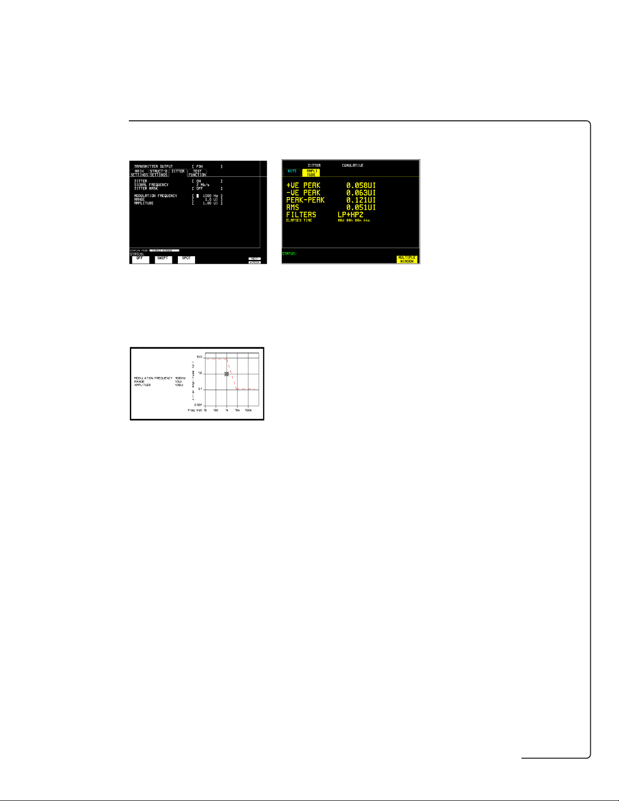
Spot frequency
features
Output jitter
Alternatively, reproduce and
further investigate those jitter
problems by generating a
specified amplitude of jitter at
a spot frequency.
The analyzer's display shows
the generated value of jitter
relative to the ITU.T mask.
Perform PDH and SDH ouput
jitter measurements to ITU-T
G.783, G.825 with ITU-T O.171
LP, HP1 and HP2 filters. RMS
jitter measurements to ITU-T
G.958 are also available with
additional 12 kHz HP filter.
11
Page 12

Capability summary
SDH and DSn/PDH supported configurations
PDH/ATM cell test
and PDH interfaces
capability
Option UKK Page 14
Unstructured PDH: 0.7, 2, 8,
34 and 140 Mb/s.
Option UKJ Page 14
Structured PDH generation
and measurement: 2, 8, 34 and
140 Mb/s.
Option UKN Page 14, 53
ATM cell generation and
analysis: 2, 34 and 140 Mb/s
(includes all capability of
option UKJ structured PDH).
Option UH3 Page 73
Binary (NRZ) clock and data
Tx/Rx interfaces plus external
clock input. Must also order
option UKK, UKJ, UKN or 110.
Option UHC Page 76
Three additional 2, 8, 34 and
140 Mb/s outputs. Must also
order option UKK, UKJ or
UKN.
Option 110 Page 18
Structured: DS1, DS3,
E1, E3.
STM-0, STM-1e test
and interfaces
Option A3R Page 22
STM-0e (52 Mb/s) and
STM-1e (155 Mb/s) electrical
interface: STM-0/STM-1
overhead access, thru mode
and pointer sequence
generation and full ITU-T
G.707 mappings.
STM-1 and STM-4
interfaces
Option UH1 Page 29, 67
STM-1 (1310 nm).
Option 130 Page 30
Combined STM-0, STM-1 and
STM-4 (1310 and 1550 nm),
STM-0, STM-1 and STM-4
overhead access, optical
power measurement.
Option 131 Page 30
Combined STM-0, STM-1 and
STM-4 (1310 nm), STM-0,
STM-1 and STM-4 overhead
access, optical power
measurement.
Option 0YH Page 72
STM-0, STM-1 and STM-4
NRZ interfaces. Must also
order option 130 or 131.
(See Note 1)
Jitter, wander
and slips testing
Option A3K Page 40
PDH and SDH jitter and
wander generation.
Option 140 Page 40
PDH and SDH jitter
generation.
Option UHN Page 45
PDH jitter measurement:
2, 8, 34 and 140 Mb/s.
Option A3L Page 45
STM-1e line and PDH jitter
measurement: 2, 8, 34, 140
and 155 Mb/s.
Option A3V Page 45
STM-1o, STM-1e line and
PDH jitter measurement: 2, 8,
34, 140 Mb/s electrical and
155 Mb/s electrical and
optical.
Option A3N Page 45
STM-4o, STM-1o, STM-1e
line and PDH jitter
measurement: 2, 8, 34, 140
Mb/s electrical, 155 Mb/s
electrical and optical and
622 Mb/s optical.
Note 1: All optical interface modules require the STM-0e/STM-1e test and interface module (option A3R).
Dual standard SONET/SDH and DSn/PDH supported configurations
PDH/DSn interfaces
Option 110 Page 18
Structured: DS1, DS3, E1, E3.
Option UKK Page 14
Unstructured PDH: 0.7, 2, 8,
34 and 140 Mb/s.
Option UKJ Page 14
Structured PDH: 2, 8, 34 and
140 Mb/s.
Option UKN Page 14, 53
ATM cell: 2, 34 and 140 Mb/s
(includes all capability of option
UKJ).
Option UH3 Page 73
Binary (NRZ) clock and data
plus external clock input. Must
also order option UKK, UKJ,
UKN or 110.
Note 1: All optical interface modules require the SONET/SDH test and interface module
(option 120).
* Jitter capability does not include DS1/DS3. Synchronous line rate measurements are to
ITU-T specifications.
SONET/SDH
test and interfaces
Option 120 Page 34
STS-1/STM-0e (52 Mb/s) and
STS-3/STM-1e (155 Mb/s)
electrical interface: Overhead
access, thru mode and pointer
sequences. Full ITU-T G.707
and Bellcore G-253 mappings.
Optical
interfaces
Option UH1 Page 29, 67
155 Mb/s (1310 nm).
Option 130 Page 30
622/155/52 Mb/s optical
interface (1310 and
1550 nm), optical power
measurement.
Option 131 Page 30
622/155/52 Mb/s optical
interface (1310 nm), optical
power measurement.
Option 0YH Page 72
622/155/52 Mb/s binary (NRZ)
interfaces. Must also order
option 130 or 131.
(See Note 1)
Option A3K Page 40
PDH, 155 Mb/s, 622 Mb/s jitter
and wander generation.
Option 140 Page 40
As option A3K, but without
wander generation.
Option UHN Page 45
PDH jitter measurement.
Option A3L Page 45
155 Mb/s electrical and PDH jitter
measurement.
Option A3V Page 45
155 Mb/s optical, electrical and
PDH jitter measurement.
Option A3N Page 45
622 and 155 Mb/s optical,
electrical and PDH jitter
measurement.
Jitter, wander and slips
testing – generation*
Jitter, wander and slips
testing – measurement*
12
Page 13

Broadband test plug-in modules
ATM cell test
and PDH interfaces
capability
Option UKN1Page 14, 53
ATM cell generation and
analysis: 2, 34 and 140 Mb/s
(includes all capability of
option UKJ structured PDH).
Option UKZ
Generation and measurement
of ATM payloads: 1.544
(DS1), 44.736 (DS3), 2.048
(E1) and 34.368 (E3) Mb/s.
1
ITU-T
2
ANSI/ITU-T
Option 0YK Page 60
Adds Channel View, graphical
display of CDV, AAL analysis,
rate history, benchmark
traffic generation. Must also
order option UKN or UKZ.
Option USL Page 60
Adds Ethernet LAN
connectivity testing plus all
features of option 0YK. Must
also order option UKN or
UKZ.
2
ATM services
layer test
Page 56
STM-1e test
and interfaces
Option A1T Page 63
STM-1e (155 Mb/s) electrical
interface from ATM testing.
Optical
interfaces
Option UH1 Page 29, 67
155 Mb/s (1310 nm).
Option USN Page 68
Combined STM-1 and STM-4
(1310 and 1550 nm) STM-1
and STM-4 overhead access,
optical power measurement.
Option UKT Page 68
Combined STM-1 and STM-4
(1310 nm), STM-1 and STM-4
overhead access, optical
power measurement.
Option UH3 Page 73
Binary (NRZ) clock and data
Tx/Rx interfaces plus
external clock input. Must
also order option UKK, UKJ
or UKN.
Jitter, wander
and slips testing
Option A3K Page 40
PDH and SDH jitter and
wander generation.
Option 140 Page 40
PDH and SDH jitter
generation.
Option UHN Page 45
PDH jitter measurement:
2, 8, 34 and 140 Mb/s.
Option A3L Page 45
STM-1e line and PDH jitter
measurement: 2, 8, 34, 140
and 155 Mb/s.
Option A3V Page 45
STM-1o, STM-1e line and
PDH jitter measurement: 2, 8,
34, 140 Mb/s electrical and
155 Mb/s electrical and
optical.
Option A3N Page 45
STM-4o, STM-1o, STM-1e
line and PDH jitter
measurement: 2, 8, 34, 140
Mb/s electrical, 155 Mb/s
electrical and optical and 622
Mb/s optical.
13
Page 14

PDH
TRANSMIT
2 8 34 140 Mb/s
RECEIVE
2 8 34 140 Mb/s
Option UKK
Unstructured PDH: 0.7, 2, 8,
34 and 140 Mb/s.
Key to all tables
● = compliance
– = non-compliance
Option UKJ*
Pair of modules providing
structured PDH generation
and measurement: 2, 8, 34
OUT
PDH & DS1/DS3
MUX
IN
75Ω
DEMUX
HANDSET
75Ω
and 140 Mb/s.
Option UKN
Pair of modules providing
ATM cell generation and
analysis: 2, 34 and 140 Mb/s
(includes all capability of
option UKJ structured
Option
UKK
Option
UKJ
Option
UKN
PDH).
PDH test options Unstructured Structured
PDH PDH
UKK UKJ* , UKN
OUT and IN ports (used for transmit and receive)
Type Electrical: To ITU-T G.703. ●●
Connectors BNC, 75 ohm, unbalanced and Siemens 3-pin, ●●
Rate PDH: 704 kb/s. ● –
120 ohm balanced.
(Small Siemens 75 ohm unbalanced option available.)
PDH: 2.048, 8.448, 34.368 and 139.264 Mb/s. ●●
ATM: 2.048, 34.368, 139.264 and 155.52 Mb/s‡. – ●
‡ For ATM you require option UKN and for 155.52 Mb/s you
also require an STM-1 test option (option A3R or A1T).
PDH transmitter
Clock timing Internal: All rates. ●●
Frequency offset generation Up to ± 100 ppm in 1 ppm steps. ●●
Test pattern PRBS (to ITU-T O.151): 2
Output 704 kb/s: HDB3 or AMI balanced/unbalanced. ● –
Bit error add 1 in 103. ●●
Recovered (loop timed): From 704 kb/s input. ● –
Recovered (loop timed): From 2.048 Mb/s input. ●●
Recovered (loop timed): From 8.448, 34.368 and 139.264 Mb/s input. – ●
15
PRBS: 29 − 1, 211 − 1 and 220 − 1. – ●
Word: User-defined 16-bit word, all ones, all zeros, 1010, 1000. ●●
2.048 Mb/s: HDB3 or AMI balanced/unbalanced. ●●
8.448 Mb/s: HDB3 or AMI unbalanced. ●●
34.368 Mb/s: HDB3 unbalanced. ●●
139.264 Mb/s: CMI unbalanced. ●●
1 in 104, 1 in 105, 1 in 106 and 1 in 107. – ●
Single error. ●●
− 1 and 223 − 1. ●●
*Adding ATM (option UKN) capability to structured PDH (option UKJ) can be accomplished via a firmware upgrade.
14
Page 15

PDH test options (continued) Unstructured Structured
PDH PDH
UKK UKJ, UKN
Frame error add 1 in 103, 1 in 104, 1 in 105, 1 in 106, 1 in 10
Code error add 2.048, 8.448, 34.368 Mb/s: 1 in 103, 1 in 104, 1 in 105, – ●
CRC4 error add 1 in 103, 1 in 104, 1 in 105, 1 in 106, 1 in 107 and single error. – ●
REBE error add 1 in 103, 1 in 104, 1 in 105, 1 in 106, 1 in 107 and single error. – ●
Alarm generation LOS, AIS, LOF, RAI, RMFAI, CASMFL. – ●
PDH & DS1/DS3
Spare bits generation The following spare bits may be modified: – ●
CAS signaling bits Modify the ABCD signaling bits (timeslot 16 CAS multiframe only). – ●
generation
Tx frame formats All rates: Unframed only. ● –
Test signal at any level N × 64 kb/s, 64 kb/s, 2.048, 8.448, 34.368 – ●
within signal structure and 139.264 Mb/s.
Test signal at interface 704 kb/s, 2.048, 8.448, 34.368 and 139.264 Mb/s. ● –
rate only
Background patterns Unframed 29 − 1 PRBS, AIS or same pattern as – ●
Ext 2 Mb/s mux input To ITU-T G.703, unbalanced HDB3 signal. – ●
and error one to four consecutive frames.
1 in 106, 1 in 107 and single error.
140 Mb/s: FAS bits 14 to 16.
34 Mb/s: FAS bit 12
8 Mb/s: FAS bit 12.
2 Mb/s Si bits (international bits): Timeslot 0 bit 1 in both FAS
and NFAS frames.
2 Mb/s E bits: CRC4 frames 13 and 15; timeslot 0 bit 1.
2 Mb/s Sa bit (national bits): NFAS timeslot bits 4 to 8 .
2 Mb/s Sa bit sequences: An 8 bit sequence may be transmitted
in any selected NFAS Sa bit when CRC4 framing has been
selected. The sequence appears in odd-numbered CRC4 frames,
starting at frame 1.
2 Mb/s CAS multiframe: MFAS timeslot bits 5, 7 and 8.
All rates: Unframed, framed and structured. – ●
2.048 Mb/s: To ITU-T G.706 and G.732 – ●
(No MFM, CAS, CRC4 MFM, CAS + CRC4 MFM).
2.048 Mb/s: N × 64 kb/s to ITU-T G.704. – ●
8.448 Mb/s: To ITU-T G.742. – ●
34.368, 139.264 Mb/s: To ITU-T G.751. – ●
foreground test signal.
7
– ●
PDH receiver
Jitter tolerance To ITU-T O.171. ●●
Equalization at f/2 To ITU-T G.703. ●●
Monitor point compensation 704 kb/s. 26 to 30 dB –
Frame formats All rates: Unframed and framed. ●●
704 kb/s. 6 dB –
2.048, 8.448 Mb/s. 6 dB 6 dB
34.368, 139.264 Mb/s. 12 dB 12 dB
2.048, 8.448 Mb/s. 26 to 30 dB 20, 26 or 30 dB
34.368, 139.264 Mb/s. 26 dB 20 or 26 dB
All rates: Structured. – ●
2.048 Mb/s: To ITU-T G.706 and G.732 ●●
(No MFM, CAS, CRC4 MFM, CAS + CRC4 MFM).
2.048 Mb/s: N × 64 kb/s to ITU-T G.704. – ●
8.448 Mb/s: To ITU-T G.742. ●●
34.368, 139.264 Mb/s: To ITU-T G.751. ●●
15
Page 16

PDH test options (continued) Unstructured Structured
PDH PDH
UKK UKJ, UKN
Frequency measurement Frequency displayed in Hz, 1 Hz resolution. ●●
Ext. 2 Mb/s demux output Nominally to ITU-T G.703, unbalanced HDB3 signal only. – ●
Autosetup Bit rate, code, framing and level of incoming signal. ●●
Errors (out-of-service ) Error count and ratio: Bit, code. ● –
Errors (ISM only†) Error count and ratio: Code, frame. ● –
PDH & DS1/DS3
Errors Error count and ratio: Bit, code, frame. – ●
Alarm indication AIS, LOS, pattern sync loss, errors present. ●●
(out-of-service)
Alarm seconds As for alarm indication above, plus power loss. ●●
(out-of-service)
Alarm indication All rates: AIS, frame loss, LOS, pattern sync loss, ● –
(ISM only†) remote alarm, errors present;
Alarm seconds As for alarm indication above, plus power loss. ● –
(ISM only†)
Alarm indication All rates: AIS, frame loss, LOS, pattern sync loss, – ●
Alarm seconds As for alarm indication above, plus power loss. – ●
G.821 analysis (Bit): EC, SES, %SES, ES, %ES, EFS, %EFS, ● –
(out-of-service) unavailability, %unavailability, degraded minutes,
G.821 analysis (Frame, CRC, REBE): EC, SES, %SES, ES, %ES, EFS, ● –
(ISM only†) %EFS, unavailability, %unavailability, degraded minutes,
G.821 analysis (Bit, frame, CRC, REBE): EC, SES, %SES, ES, %ES, – ●
G.826 analysis Errored blocks (EB), errored seconds (ES), severely errored – ●
(CRC, REBE) seconds (SES), unavailable second count (UAS),
M.2100 error analysis Same as G.821 (bit errors only). ● –
(out-of-service)
M.2100 error analysis (Frame, CRC, REBE): Tx ES, Tx SES, Rx ES, Rx SES, ● –
(ISM only†) unavailability.
M.2100 error (Bit frame, CRC, REBE): Tx ES, Tx SES, Tx UNAV, Rx ES, – ●
analysis Rx SES, Rx UNAV.
M.2110 bringing into 2 hour, 24 hour and 7 day PASS/–?–/FAIL indication. – ●
service test Run a 24 hour out-of-service test using a PRBS. After
Offset displayed in ppm and Hz.
Test pattern for unframed and framed signals.
CRC4 (2.048 Mb/s only),
REBE (2.048 Mb/s only).
2 Mb/s: CAS/CRC multiframe loss, remote multiframe alarm.
remote alarm, minor alarm, errors present;
2 Mb/s: CAS/CRC multiframe loss,
remote multiframe alarm.
%degraded minutes, code error seconds, elapsed time
(including Annex D).
%degraded minutes, code error seconds,
elapsed time.
EFS, %EFS, unavailability, %unavailability,
degraded minutes, %degraded minutes, code error seconds,
elapsed time (including Annex D for bit errors).
path unavailable second count (PUAS), background block
error count (BBE), errored second ratio (ESR), severely
errored second ratio (SESR), background block error
ratio (BBER).
24 hours the instrument compares ES, SES and UAS results
against the S1 and S2 thresholds derived from the path
allocation and flags either PASS/–?–/FAIL. The 7 day
test is then performed on uncertain paths (–?–) during
the 24 hour test, ie, run contiguously for a further 6 days.
† ISM = In-service measurement mode on framed signals (unstructured PDH option UKK).
16
Page 17

PDH test options (continued) Unstructured Structured
PDH PDH
UKK UKJ, UKN
M.2120 in-service test Contiguous 15 minute (T1) and 24 hour (T2) periods – ●
for maintenance with TR1 and TR2 threshold reports. Based on the user
entered path allocation and maintenance factors, the
T1-ES, T1-SES, T2-ES and T2-SES thresholds are
calculated. A single threshold report (TR1 for 15 minute,
TR2 for 24 hour) is generated when any of the relevant
thresholds are exceeded within each 15 minute or
24 hour period.
PDH & DS1/DS3
Spare bit display At all rates. NFAS (2 Mb/s), multiframe sync (2.048 Mb/s CAS), ● –
(ISM only†) FAS (8.448, 34.368 to 139.264 Mb/s).
Error output One pulse per bit error or code error. ● –
Round trip delay Up to 2 seconds delay between transmit and receive. – ●
Alarm scan Automatically scans the PDH network hierarchy – ●
CAS signaling Displays the ABCD signaling status of all 30 timeslots – ●
bit monitor (timeslot 15 CAS multiframe only).
N ´ 64 kb/s To ITU-T G.704; 1 to 31 contiguous and – ●
Telephone handset Provides full talk/listen capability – RJ11 connector – ●
connection (Telephone handset accessory available – HP 15722A).
† ISM = In-service measurement mode on framed signals (unstructured PDH option UKK).
Nominal ECL, 75 ohm −2 V BNC.
for alarms (frame loss, AIS and remote alarms).
non-contiguous timeslots.
17
Page 18

DS1/DS3/E1/E3 structured test interfacing
Option 110
Pair of modules providing structured
DSn and PDH generation and
measurement at DS1 (1.5 Mb/s),
DS3 (45 Mb/s) and E1 (2 Mb/s),
E3 (34 Mb/s ).
PDH & DS1/DS3
Option 110
DS1/DS3/E1/E3 structured test interfaces Structured
DSn/PDH
110
OUT and IN ports (used for transmit and receive)
Type Electrical: To ANSI T1.102-1993; ITU-T O.171, G.703. ●
Connectors DS1 (1.554 Mb/s): WECO bantam, 100 ohm balanced. ●
Rate 1.544, 2.048, 34.368, 44.736 Mb/s. ●
DSn/PDH transmitter
Clock timing Internal: All rates; ●
Frequency offset generation Up to ± 100 ppm in 1 ppm steps. ●
Clock output Selected transmitter clock (internal or looped receiver clock) used ●
Line coding DS1: B8ZS, AMI. ●
Output level DS1: DSX-1, DS1-LO. ●
DS3 (44.736 Mb/s): BNC, 75 ohm, unbalanced.
E1 (2.048 Mb/s): BNC, 75 ohm, unbalanced and WECO bantam,
120 ohm balanced.
E3 (34.368 Mb/s): BNC, 75 ohm, unbalanced.
Recovered by the receiver.
to generated DS1/DS3/E1/E3 test output signal.
(BNC connector, externally terminated 50 ohm to ground).
DS3: B3ZS.
E1: AMI, HDB3.
E3: HDB3.
DS3: DS3-HI, DSX-3, DS3-900'
18
Page 19

DS1/DS3/E1/E3 structured test interfaces (continued) Structured
DSn/PDH
110
Framing All rates: Unframed, framed and structured. ●
PDH & DS1/DS3
Test pattern PRBS: 29 – 1, 2
Error add DS1: Bit, FAS (Frame Alignment Signal), BPV/code, CRC-6, EXZ (excess zeros). ●
Error insertion rate Single. ●
Alarm generation DS1: Loss of signal (LOS); Out of frame (OOF); alarm indication signal (AIS); ●
FEAC code generation With C-Bit parity framing loopback and alarm/status codes as per ●
Spare bits generation The following spare bits can be modified; ●
Signaling bits generation DS1: User selectable Signaling ON or OFF. When ON user selectable ●
DS1: SF (D4), SLC-96.
DS1: ESF to ANSI T1.403-1989, Bellcore TR-TSY-000499 and ITU-T G.704;
the ESF data link (DL) defaults to repetition of idle code (01111110).
DS3: M13 to ANSI T1.107-1995.
DS3: C-bit parity to ANSI T1.107a-1990.
E1: To ITU-T G.706/G.732.
E3: To ITU-T G.751.
N × 64 kb/s structured to ITU-T G.704 for E1, E3
N × 64 kb/s and N x 56 kb/s structured for DS1 and DS3.
11
15
20
– 1, 2
QRSS (DS1 only).
3-in-24 stress pattern (DS1 only).
Word: 1010, 1000, 16 bit user word, all ones, all zeros.
The PRBS polarity of patterns is user selectable.
DS3: Bit, FAS, MFAS (MultiFrame Alignment Signal), BPV/code, parity(P bits),
CP (path parity), FEBE, EXZ (excess zeros).
E1: Bit, FAS, BPV/code, CRC-4, REBE.
E3: Bit, FAS, BPV/code.
1.0E – 3.
1.1E – 3.
1.0E – 4 to 9.9E-9. Mantissa step size 0.1, exponent step size 1.
remote alarm indication (RAI).
DS3: LOS; LOF; AIS; RAI; far end alarm and control (FEAC): As per T1.107-1995.
E1: LOS, LOF, AIS, RAI.
E3: LOS, LOF, AIS, RAI.
ANSI T1.107-1995 can be generated.
Loopback codes: A single burst of N loopback codes and M messages
where N and M are in the range 1 through 15.
Alarm/status codes: Any ANSI T1.107-1995 message or any
0xxxxxx011111111, message where x is selectable, may be transmitted
either in a single burst of 1 to 15 times or continuously.
34 Mb/s: FAS bit 12
2 Mb/s Si bits (international bits): Timeslot 0 bit 1 in both FAS
and NFAS frames.
2 Mb/s E bits: CRC4 frames 13 and 15; timeslot 0 bit 1.
2 Mb/s Sa bit (national bits): NFAS timeslot bits 4 to 8 .
2 Mb/s Sa bit sequences: An 8 bit sequence may be transmitted
in any selected NFAS Sa bit when CRC4 framing has been
selected. The sequence appears in odd-numbered CRC4 frames, starting at frame 1.
2 Mb/s CAS multiframe: MFAS timeslot bits 5, 7 and 8.
AB bits for SF, ABCD for ESF and AB bits for SLC-96 framing.
– 1, 2
23
– 1, 2
– 1 . ●
Background patterns Unframed 29 – 1 PRBS, AIS or same as test pattern as foreground ●
test signal.
Ext DS1 mux input Weco bantam connector, AMI or B8ZS. ●
Ext 2 Mb/s mux input BNC to ITU-T G.703, AMI or B8ZS. ●
19
Page 20

DS1/DS3/E1/E3 structured test interfaces (continued) Structured
DSn/PDH receiver
Type, connectors, rates, As for DSn/PDH transmitter. ●
line code and framing
Jitter tolerance To Bellcore TR-TSY-000009 (DS1/DS3) and ITU-T O.171. ●
Operating level (terminate) User selectable as follows: ●
PDH & DS1/DS3
Monitor point DS1 (balanced), E1 (balanced and unbalanced): 20, 26 or 30 dB gain relative ●
compensation to terminate mode. E1 (balanced) is restricted to half cable length with
Framing All rates: Unframed , framed and structured. ●
Frequency measurement Frequency displayed in Hz, 1 Hz resolution. ●
Error results DS1 (counts & ratios): Bit, B8ZS/AMI code violations, frame errors, CRC6 errors. ●
Alarm indication DS1:LOS, pattern loss, AIS, OOF, Multiframe Loss, RAI, EXZ, Idle ●
FEAC code indication With C-Bit parity framing loopback and alarm/status codes are decoded
G.826 analysis Errored blocks (EB), errored seconds (ES), severely errored ●
G.821 analysis EC, SES, %SES, ES, %ES, EFS, %EFS, unavailability, %unavailability, ●
M.2100 analysis Tx ES, Tx SES, Rx ES, Rx SES, unavailability ●
M.2110 bringing into 2 hour, 24 hour and 7 day PASS/–?–/FAIL indication. ●
service test Run a 24 hour out-of-service test using a PRBS. After
DS1 (balanced): DSX-1 to DS1-LO levels.
DS3 (unbalanced): DS3-HI, DSX-3 and DS3-900 levels.
E1 (balanced): 3.0 V ± 20% for cable lengths as per ITU-T G.703.
E1 (unbalanced): 2.37 V ± 20% for cable lengths as per ITU-T G.703.
E3 (unbalanced): 1.0 V ± 20% with automatic equalization for cable lengths
as per ITU-T G.703.
respect to ITU-T G.703 for 26 and 30 dB gains.
DS3 and E3: 20 or 26 dB gain relative to terminate mode.
DS1: SF (D4), SLC-96.
DS1: ESF to ANSI T1.403-1989, Bellcore TR-TSY-000499 and ITU-T G.704.
DS3: M13 to ANSI T1.107-1995.
DS3: C-bit parity to ANSI T1.107a-1990.
E1: To ITU-T G.706/G.732
E3: To ITU-T G.751
N × 64 kb/s structured to ITU-T G.704 for E1, E3
N × 64 kb/s and N x 56 kb/s structured for DS1 and DS3.
Offset displayed in ppm and Hz.
DS3 (counts & ratios): Bit, B3ZS code violations, frame errors, P-parity,
CP-parity, FEBE.
E1 (counts & ratios): Bit, HDB3/AMI code violations, frame errors,
CRC4, REBE.
E3 (counts & ratios): Bit, HDB3 code violations, frame error.
DS3:LOS, Pattern loss, AIS, OOF, Multiframe Loss, RAI, EXZ, Idle
E1: LOS, Pattern loss, AIS, LOF, RAI, RMFAI, CASMFL
E3: LOS, Pattern loss, AIS, LOF, RAI
and displayed. Displays shows current and last active FEAC message. ●
seconds (SES), unavailability seconds (UAS), error second ratio (ESR),
severely errored second ratio (SESR), background block error ratio (BBER),
path unavailable seconds (PUAS).
degraded minutes, (%) degraded minutes, code error seconds,
elapsed (including Annex D for bit errors)
24 hours the instrument compares ES, SES and UAS results
against the S1 and S2 thresholds derived from the path
allocation and flags either PASS/–?–/FAIL. The 7 day
test is then performed on uncertain paths (–?–) during
the 24 hour test, ie, run contiguously for a further 6 days.
DSn/PDH
110
20
Page 21

DS1/DS3/E1/E3 structured test interfaces (continued) Structured
M.2120 in-service test Contiguous 15 minute (T1) and 24 hour (T2) periods ●
for maintenance with TR1 and TR2 threshold reports. Based on the user
PDH & DS1/DS3
Signaling monitor DS1: Signaling bit state is displayed. ABCD format for ESF and ●
Alarm scan Alarms at the Interface Rate and at all lower levels in the hierarchy ●
entered path allocation and maintenance factors, the
T1-ES, T1-SES, T2-ES and T2-SES thresholds are
calculated. A single threshold report (TR1 for 15 minute,
TR2 for 24 hour) is generated when any of the relevant
thresholds are exceeded within each 15 minute or
24 hour period.
AB for SF/SLC-96. SLC-96 can display one of three states;
0,1 or alternating.
E1: Graphical display, simultaneously showing the ABCD
signalling status of all 30 channels is available.
are scanned continuously. A graphical picture of the hierarchy is shown
which displays the alarm state for all streams.
DSn/PDH
110
21
Page 22

STM-0/STM-1e test and interfacing
SDH
Option A3R
STM-0e (52 Mb/s) and STM-1e (155 Mb/s)
electrical interface: STM-0/STM-1 overhead
access, thru mode and pointer sequence
generation. Full ITU-T G.707 mappings plus
frequency offset generation, alarm and error
generation/detection plus an error output, SDH
alarm and BIP scan, tributary scan and protection
switch times.
Option A3R
SDH ITU-T G.707 mapping structure
22
Page 23

SDH
STM-0/STM-1e test and interfacing options (continued) STM-0/STM-1e
testing
A3R
OUT and IN ports (used for transmit)
Type Electrical: To ITU-T G.703. ●
Connectors BNC, 75 ohm, unbalanced. ●
Rate 155.52 Mb/s. ●
Line code 155.52 Mb/s: CMI. ●
Output level 155.52 Mb/s: ± 0.5 V ± 10%. ●
Error output B3 error output pulse on receipt of STM-0 and STM-1 signals. ●
Simultaneous STM-1e/ When used in conjunction with the appropriate optical interfaces, ●
STM-1e and STM-1o transmit STM-1 electrical output signal simultaneously with
Transmitter
Clock timing Internal: All rates. ●
Frequency offset Up to ± 999 ppm in 0.1 ppm steps. ●
generation
Error addition ●
(Small Siemens 75 ohm unbalanced option available.)
51.84 Mb/s. ●
51.84 Mb/s: B3ZS. ●
51.84 Mb/s: ●
Output level is user configurable.
STM-0 X CON: 1.1 V peak nominal (0 ft).
STM-0 HI: 530 mV peak nominal (450 ft).
STM-0 LOW: 350m V peak nominal (900 ft).
TTL pulse termination 75 ohm or 10 kohm.
STM-1 optical output signal.
Recovered: From SDH input (CMI or NRZ electrical or optical). ●
Ext MTS: 64 kb/s conforming to ITU-T G.703, 2 Mb/s conforming to ITUT-G.811. ●
BNC, 75 ohm, unbalanced or Siemens (3-pin), 120 ohm, balanced. ●
(Siemens (3-pin) connector is present on option A3R.
Option 120 replaces this connector with a Bantam connector).
Error type Single Rate 10
Frame A1A2 ● N in four
B1 ● 4 to 9
B2† ● 3 to 9
MS REI ● 3 to 9
AU-4 path BIP-8 (B3) ● 4 to 9
AU-4 path REI ● 4 to 9
AU-4 path IEC ● 4 to 9
AU-3 path BIP-8 (B3) ● 4 to 9
AU-3 path REI ● 4 to 9
AU-3 path IEC ● 4 to 9
TU-3 path BIP-8 (B3) ● 3 to 9
TU-3 path REI ● 3 to 9
TU-2 path BIP (V5) ● 4 to 9
TU-2 path REI ● 5 to 9
TU-12 path BIP (V5) ● 3 to 9
TU-12 path REI ● 4 to 9
TU-11 path BIP ● 3 to 9
TU-11 path REI ● 4 to 9
Bit error* ● 3 to 9
-N
Comments
frame words
† MSP threshold N errors in T ms
where 0 ≤ N ≤ 1920 (STM-1) and
10 ms ≤ T ≤ 10000 s, in decade
steps.
* For SDH stand-alone operation,
bulk-filled payloads and DS1, DS3
mapped payloads only. For bit
error rates supported with other
payloads refer to the PDH test
option for details.
23
Page 24

SDH
STM-0/STM-1e test and interfacing options (continued) STM-0/STM-1e
testing
A3R
Alarm generation LOS, LOF, OOF, MS AIS, MS RDI, ●
Payload capability
STM-0/STM-1/STM-4 139.264 Mb/s into a VC-4 and VC-4 bulk-filled mappings. ●
payload mappings 34.368 Mb/s into VC-3 and VC-3 bulk-filled mappings.
(to ITU-T G.707) 2.048 Mb/s (async and fl. byte sync) into VC-12 and VC-12 bulk-filled mappings.
Payload data The following unframed patterns can be generated:
Payload framing 139.264, 34.368 and 2.048 Mb/s: Unframed. ●
Drop/insert 139.264Mb/s: Drop/insert via Tx/Rx on options UKJ/UKN. ●
AU-4 path AIS, AU-4 path RDI, AU-4 LOP, AU-4 path unequipped,
AU-3 path AIS, AU-3 path RDI, AU-3 LOP, AU-3 path unequipped,
TU-3 path AIS, TU-3 path RDI, TU-3 LOP, TU-3 path unequipped,
TU-2 path AIS, TU-2 path RDI, TU-2 LOP, TU-2 path unequipped,
TU-2 H4 LOM (loss of multiframe),
TU-12 path AIS, TU-12 path RDI, TU-12 LOP, TU-12 path unequipped,
TU-12 H4 LOM (loss of multiframe),
TU-11 path AIS, TU-11 path RDI, TU-11 LOP, TU-11 path unequipped,
TU-11 H4 LOM (los of multiframe).
DS3 (44.736 Mb/s) into VC-3 and VC-3 bulk-filled mappings†
DS1 (1.544 Mb/s) async into VC-11†.
VC-3 - TU-3 - TUG-3 - VC-4 - AU-4;
VC-3 - AU-3.*
VC-2 bulk filled mapping and TU-2-Nc (for N = 2 to 6):
VC-2 - TU-2 - TUG-2 - TUG-3 - VC-4 - AU-4.
VC-2 - TU-2 - TUG-2 - VC-3 - AU-3.*
VC-12 - TU-12 - TUG-2 - TUG-3 - VC-4 - AU-4.
VC-12 - TU-12 - TUG-2 - TUG-3 - VC-3 - AU-3.*
VC-11 - TU-11 - TUG-2 - TUG-3 - VC-4 - AU-4.†
VC-11 - TU-11 - TUG-2 - VC-3 - AU-3.*†
† DS1 and DS3 mappings require PDH options UKJ, UKN or 110 to be fitted.
* AU-3 mappings require HP OmniBER 717 analyzer mainframe.
(Framed and structured signals are available in conjunction
with the PDH/DSn option UKJ/UKN/110).
PRBS: 29 − 1 (O.150), 2
23
and 2
− 1 (O.151)
20
QRSS (2
Word: User-defined 16-bit word, all ones, all zeros, 1010, 1000.
All PRBS patterns can be set to inverted or non-inverted.
† Applicable to DS1 mappings only.
139.264, 34.368 and 2.048 Mb/s: Framed and structured†.
DS3 payloads: Unframed, C-Bit parity (to ANSI T1.107a-1990)†
M13 (to ANSI T1.107-1988).
TU-2: Unframed.
DS1 payloads: Unframed, SF (D4), ESF (to ANSI T1.403-1989,
TR-TSY-000499 and ITU-T G.704), SLC-96†.
† Only available in conjunction with the PDH/DSn option UKJ/UKN/110.
44.736 (DS3): Drop/insert via Tx/Rx on option 110.
34.368 Mb/s: Drop/insert via Tx/Rx on options UKJ/UKN/110.
2.048 Mb/s: Drop/insert via drop/insert ports on options UKJ/UKN/110.
1.544 Mb/s: Drop/insert via drop/insert ports on option 110.
− 1, 14 zero limited)†
11
− 1 (O.152), 2
15
− 1 (O.151) ●
24
Page 25

SDH
STM-0/STM-1e test and interfacing options (continued) STM-0/STM-1e
testing
A3R
Pointer adjustment generation
Increment/decrement/ Provides a burst, selectable between 1 and 10 pointer ●
alternating adjustments (between 1 and 5 for TU-12 or TU-11 pointer).
New pointer value The AU-4, AU-3, TU-3, TU-2, TU-12 or TU-11 moves to a selectable new ●
Frequency offset Pointer sequences are generated by offsetting the ●
(and 87:3) frequencies of the AU-4, AU-3 (in these modes the 87:3 sequence is
ITU-T G.783 sequences Bursts of periodic single adjustments with added or canceled ●
Transmit overhead
Overhead Default selection: Standard overhead values to ITU-T G.707. ●
SOH user-settable SOH can be set in binary or HEX. ●
bytes RSOH: A1, A2, J0, E1, F1, D1 to D3.
Overhead sequence A single or multi-byte overhead channel is overwritten with ●
generation a single or repeated sequence of programmed values.
location in a single jump, with or without an accompanying
new data flag (NDF).
generated to ITU-T G.783) or TU-3, TU-2, TU-12, TU-11 and the line
rate relative to each other.
Range: ± 100 ppm in 0.1 ppm steps.
adjustments. Polarity is selectable.
Bursts of periodic double adjustments with pairs alternating
in polarity. In all cases the interval between adjustments or
pairs of adjustments is programmable.
On starting to run any of the pointer
sequences an initialisation sequence followed by a cool down
period may be run prior to the chosen sequence.
J0 path trace: User-defined/predefined 16-byte
ITU-T E.164 sequence.
MSOH: K1, K2, D4 to D12, S1, M1, Z1†, Z2†, E2 (and access to
bytes reserved for national use plus all bytes reserved
for future international standardization).
VC-4 and VC-3 POH: J1, C2, G1, F2, H4, F3, K3, N1. ●
J1 path trace: User-defined/predefined 16-byte
ITU-T E.164 sequence or 64-byte sequence.
VC-2, VC-12, VC-11 POH: V5, J2, N2, K4. ●
J2 path trace: User defined/predefined 16-byte
ITU-T E.164 sequence.
† Z1 and Z2 are not present in STM-0 mode.
The sequence can contain up to five different values each
being transmitted for up to 64,000 frames.
RSOH:
6-byte channel A1A2
3-byte channel D1 to D3
Single byte channels: C1, E1, F1.
MSOH:
9-byte channel D4 to D12
2-byte channel K1K2.
Single byte channels: S1, M1, Z1†, Z2†, E2.
† Z1 and Z2 are not present in STM-0 mode.
High order POH:
Single byte channels: J1, C2, G1, F2, H4, F3, K3, N1.
25
Page 26

SDH
STM-0/STM-1e test and interfacing options (continued) STM-0/STM-1e
testing
A3R
Overhead BER test Any RSOH, MSOH or POH (except A1, A2, H1, H2, Z1, Z2) ●
MSP message Messages are displayed in text form as per ITU-T G.783 ●
generation for linear architecture and to ITU-T G.841 for ring
DCC drop/insert The data supplied to the DCC port can be inserted into either ●
Optical interface 2 to 259 bytes of the payload are overwritten with a block ●
stress test of zeros or ones after scrambling.
Tributary scan Automatically test BER on each SDH tributary for error ●
Mixed payloads Backgrounds can be individually configured to have TU-11, TU-12 ●
Keep alive signals PDH: Transmit last configured SDH signal while transmitting ●
channel is selected and a BER measurement is performed
using a 29 − 1 PRBS inserted into a 64 kb/s channel.
Single errors can be added to the test pattern.
architectures (MSP-ring).
User programmed sequences (K1K2). ●
the regenerator section or multiplexer section data
communications channel. Similarly, data can be dropped
from either channel. The data may be dropped/inserted
MSB or LSB first. The data rate for access is: 192 kb/s
(RSOH DCC), 576 kb/s (MSOH DCC).
Alternatively the ITU-T G.958 CID (consecutive identical digits)
test can be selected.
free operation.
Rx setup is used to determine tributary structure and test pattern.
Alarms: Pattern loss.
Test time: Fully user selectable.
User selectable bit error threshold: Off, > 0, ≥ 10−3, ≥ 10−6.
or TU-3 independently of foreground testing channel.
a PDH signal.
SDH: With structured PDH options transmit unframed fixed
word PDH signal while transmitting an SDH signal.
SDH: Using unstructured PDH option transmit last
configured PDH signal while transmitting an SDH signal.
Thru mode
Transparent The signal is passed through the instrument without being ●
thru mode altered for monitoring purposes where no protected monitor
point is available.
Overhead overwrite In addition to the above, the test features associated with the ●
thru mode SOH and POH can be enabled to control one single- or
multi-byte overhead channel (ie, errors and alarms, optical
stress test, overhead sequences, MSP messages, DCC insert,
overhead BER. Full Rx functionality also available).
AU-4/AU-3 overwrite In addition to both of the above, overwrite the complete AU-4/AU3 ●
thru mode with the internally generated payload. This enables the SOH
to be looped through while a new payload is inserted.
All of the test features which affect the VC-4/VC-3 and/or the
POH are enabled (ie, errors and alarms, adjust pointer,
overhead sequences, MSP messages, overhead BER. Full Rx
functionality also available).
Tributary overwrite When the payload passing through the instrument contains ●
thru mode a TU structure, thru mode it will be possible to choose a single
TU to be overwritten, as opposed to the complete payload.
All of the test features which affect the TU and/or the POH
are enabled (ie, errors and alarms, adjust pointer.
Full Rx functionality also available).
26
Page 27

SDH
STM-0/STM-1e test and interfacing options (continued) STM-0/STM-1e
testing
A3R
STM-1e and STM-0/STM-1e receiver functions
STM-1 receive input
Equalization Automatic for cable loss up to 12 dB at half the bit rate. ●
Monitor point Monitor mode conforms to ITU-T G.772. ●
compensation Monitor gain. 20 to 26 dB
STM-0 receive input
Operating level Receiver mode is user selectable. ●
STM-0 HI: 1.1 V peak nominal, equalization up to 450 ft
STM-0 LOW: 1.1 V peak nominal, equalization from 450 to 900 ft
Monitor point Monitor mode conforms to ITU-T G.772. ●
compensation Monitor gain. 20 to 26 dB
Results
Error results Frame (A1A2), B1, B2, MS REI, ●
AU-4 path BIP (B3), AU-4 path REI, AU-4 path IEC,
AU-3 path BIP (B3), AU-3 path REI, AU-3 path IEC,
TU-3 path BIP (B3), TU-3 path REI,
TU-2 path BIP (V5), TU-2 path REI,
TU-12 path BIP (V5),TU-12 path REI,
TU-11 path BIP (V5), TU-11 path REI,
bit errors (bulk filled, PDH payload).
AU-3 path BIP (B3), AU-3 path REI, AU-3 path IEC . ●
DS1/DS3 error results Frame error, CRC6 error (DS1 ESF), P-bit parity (DS3), ●
C-bit Parity (DS3 CBP framing), REI (DS3 CBP framing).
Bit errors (DS1 and DS3).
Error analysis To ITU-T G.826 in-service and out-of-service ●
(G.821 and M.2100/2101/2110/2120 for PDH payload).
Alarm indication LOS, LOF, OOF, MS AIS, MS RDI, K1K2 change ●
AU-3 path AIS, AU-3 path RDI, AU-3 LOP, AU-3 pointer adj
AU-4 path AIS, AU-4 path RDI, AU-4 LOP, AU-4 pointer adj
TU-3 path AIS, TU-3 path RDI, TU-3 LOP, TU-3 pointer adj
TU-2 path AIS, TU-2 path RDI, TU-2 LOP, TU-2 pointer adj
TU-12 path AIS, TU-12 path RDI, TU-12 LOP, TU-12 pointer adj
TU-11 path AIS, TU-11 path RDI, TU-11 LOP, TU-11 pointer adj
H4 multiframe sync loss, pattern sync loss, clock loss,
power loss and errors (any type).
DS1/DS3 alarm indication: AIS, frame loss, RDI. ●
Alarm seconds As for alarm indication, plus NDF, missing NDF and clock loss. ●
AlarmScan plus Automatically scans the SDH network hierarchy for alarms ●
alarm and BIP scan and BIP errors or alarms only with a graphical display of the
network hierarchy’s status including the indication of
unequipped channels.
Alarms: LOP, path AIS, path RDI, H4 LOM†, TU LOP*,
TU path AIS*, TU path RDI.*
† For TU-11, TU-12 and TU-2 structures.
* If applicable.
BIP errors:
AU-4 payloads: VC-4 B3.
AU-3 payloads: VC-3 B3.
TU-3 payloads: VC-4 B3 and VC-3 B3.
TU-2/TU-12/TU-11 payloads: VC-4/VC-3 B3 and V5 BIP-2.
User selectable BIP error threshold: Off, > 0, > 10−3, > 10−6.
27
Page 28

SDH
STM-0/STM-1e test and interfacing options (continued) STM-0/STM-1e
testing
A3R
Protection switch times Service disruption test measures error burst length for ●
Pointer results AU pointer value, AU NDF seconds, AU missing NDF seconds, ●
Frequency Frequency displayed in Hz, 1 Hz resolution. ●
measurement Offset displayed in ppm and Hz.
Received overhead SOH can be set in binary or HEX. ●
snapshot SOH and POH of a received STM-1 signal. ●
Overhead sequence Any one overhead channel is selected. After a manual ●
capture or programmed trigger, the captured byte values are displayed
Pointer A graphical display that shows the variation with time of the ●
location graph AU-n and TU-n pointer location. Up to four days of pointer
Overhead BER Any RSOH, MSOH or POH (except A1, A2, H1, H2, Z1, Z2) ●
measurement channel is selected and a BER measurement is performed
measurement of protection switch times†.
Accuracy: < 50 µs.
Results: Longest burst length, shortest burst length,
last burst length.
Resolution: 1 µs.
† Service disruption test requires PDH/DSn option UKJ,
UKN or 110 to be fitted.
AU +ve adjustment count/seconds, AU −ve adjustment
count/seconds, TU pointer value, TU NDF seconds,
TU missing NDF seconds, TU +ve adjustment count/seconds,
TU −ve adjustment count/seconds, implied VC-4, VC-3, VC-2,
VC-12, VC-11 offset.
SOH and POH of a received STM-0 signal. ●
Text message displayed for signal label (C2 and V5) and
sync status (S1) decoded.
together with the number of consecutive frames containing
the value.
location activity can be monitored.
Implied VC offset: The total positive and negative pointer
movements since the start of the measurement period are
summed and the implied mean VC offset calculated from
this total.
using a 29 − 1 PRBS inserted into a 64 kb/s channel. Single
errors can be added to the test pattern. Error count,
error ratio, error free seconds, % error free seconds and
pattern loss seconds are measured.
28
Page 29

STM-1 optical interfacing
SDH
Option UH1
STM-1 (1310 nm) optical
interfacing. Also provides
STM-1
LASER
ON
OUT
CLASS 1 LASER PRODUCT
IN
Option UH1
OC-3 optical interfacing when
used in conjunction with dual
standard SONET/SDH
option 120.
STM-1 optical interfacing options STM-1
Requires option A1T, A3R or 120 to be fitted.
OUT and IN ports (used for transmit and receive)
Type Optical. ●
Connectors Customer exchangeable optical adaptors allow a range of interfaces to be attached.
Rate STM-1 (155.52 Mb/s). ●
Line code NRZ. ●
Transmitter
Wavelength 1280 to 1330 nm. ●
Spectral width (3 dB) 2.5 nm rms. ●
Optical power output Nominal. −9 dBm
Source type SLM (single mode). ●
Tx classification to STM-1 (parameters Table 2 G.957):
ITU-T G.957 S-1.1 (1310 nm). ●
Safety classification Class 1 (EN 60825-1): 1994. ●
Class I (21 CFR CH1 1040.10 (1996). ●
Receiver
Wavelength 1270 to 1600 nm. ●
Minimum sensitivity Using 1300 nm wavelength, 100% modulation depth and BER of 10
and PRBS of 2
Maximum input power For BER of 10
Detector type MLM (multi mode).* ●
Rx classification to STM-1 (parameters Table 2 G.957):
ITU-T G.957 S-1.1 (1310 nm); ●
S-1.2 (1550 nm). ●
Alarms detected Loss of optical signal. ●
23
− 1.
−10
. −8 dBm
−10
(1310 nm)
UH1
−28 dBm
* MLM receivers work with both MLM (multi mode) and SLM (single mode) transmitters.
29
Page 30

STM-4c, STM-4, STM-1 and STM-0 test and optical interfacing
SDH
Option 130
STM-4c/STM-4/STM-1 and STM-0
overhead access, thru mode. Dual
1310 and 1550 nm optical
interfaces and optical power
measurement.
Option 131
STM-4c/STM-4/STM-1 and STM-0
overhead access, thru mode.
1310 nm optical interfaces and
optical power measurement.
Both modules also provide
OC-12c/OC-12/OC-3c/OC-3
and OC-1 overhead access
and thru mode when used in
Option 130
Option 131
conjunction with option 120.
STM-4c, STM-4, STM-1 and STM-0 test 130 131 and interfacing options
Requires option A3R or 120 to be fitted.
OUT and IN ports (used for transmit and receive)
Type Optical. ●●
Electrical monitor point. ●●
Connectors Customer exchangeable optical adaptors allow a range of interfaces ●●
to be attached.
Electrical monitor port: SMA (50 ohm ECL). ●●
Rate STM-0 (51.84 Mb/s). ●●
STM-1 (155.52 Mb/s). ●●
STM-4 (622.08 Mb/s). ●●
Line code NRZ. ●●
Transmitter
Wavelength 1280 to 1330 nm at STM-0, STM-1, STM-4. ●●
1520 to 1565 nm at STM-1, STM-4. ● –
Spectral width (3dB) 2.5 nm rms. ●●
Extinction ratio > 8.2 dB nominal 1310 nm. ●●
> 10 dB nominal 1550 nm. ● –
Optical power output 1310 nm nominal. −10 dBm −10 dBm
1550 nm nominal. −1 dBm –
Source type SLM (single mode). ●●
Tx classification to STM-1 (parameters Table 2 G.957):
ITU-T G.957 S-1.1 (1310 nm); ●●
L-1.2 (1550 nm). ● –
STM-4 (parameters Table 3 G.957):
S-4.1 (1310 nm); ●●
L-4.2 (1550 nm). ● –
Safety classification Class I (FCC 21 CFR CH.1 1040.10 (1994)). ●●
Class 3A (EN 60825-1:1994). ●●
(1310 and (1310 nm)
1550 nm)
30
Page 31

SDH
STM-4c, STM-4, STM-1 and STM-0 test 130 131
and interfacing options (continued)
Receiver
Wavelength 1200 to 1600 nm. ●●
Minimum sensitivity Using 1300 nm wavelength, 100% modulation depth and BER of 10
and PRBS of 2
52 , 155 Mb/s. −34 dBm −34 dBm
622 Mb/s. −28 dBm −28 dBm
Maximum input power For BER of 10
Detector type MLM (multi mode)*. ●●
Rx classification to STM-1 (parameters Table 2 G.957):
ITU-T G.957 S-1.1, L-1.1 (1310 nm); ●●
S-1.2, L-1.2 (1550 nm). ●●
STM-4 (parameters Table 3 G.957):
S-4.1, L-4.1 (1310 nm); ●●
S-4.2, L-4.2 (1550 nm). ●●
Protected monitor 150 mV to 1000 mVp-p (nominal): ac coupled, nominal 50 ohm. ●●
point input level
Optical power measurement Accuracy: ± 1 dB . ●●
Range: −8 to −30 dBm.
23
− 1. To ITU-T G.957.
−10
. −8 dBm −8 dBm
Transmitter functions
Clock timing Internal. ●●
Frequency offset generation Up to ± 999 ppm in 0.1 ppm steps. ●●
STM-4 error addition
Recovered:
From received STM-0, STM-1 or STM-4 optical signal. ●●
From received STM-0, STM-1 electrical signal. ●●
Ext. MTS: Data or clock format (as ITU-T G.811). ●●
-
Error type Single Rate 10
N
Comments ●●
−10
(1310 and (1310 nm)
1550 nm)
Frame A1A2 ● N in four frame words
B1 ● N = 4 to 9
B2 % ● N = 3 to 9
MS REI ● N = 3 to 9
% MSP threshold, N in T where 0 ≤ N ≤ 1920 and 10 ms ≤ T ≤ 10000 s,
in decade steps.
STM-1 One STM-1 is selected for test. STM-1 error add capability ●●
error addition is provided for the STM-1 under test. Refer to STM-0/STM-1
STM-4 alarm generation LOS, LOF, OOF, MS AIS, MS RDI. ●●
STM-1 alarm generation One STM-1 is selected for test. For STM-1 alarm generation ●●
Payload capability One STM-1 is selected for test. The payload data capability of the ●●
Background payload Background STM-1 contains 00000000 in all bytes or VC-4 payload
VC-4-4c error add
* MLM receivers work with both MLM (multi mode) and SLM (single mode) transmitters.
test option A3R for details.
capability of the STM-1 under test, refer to STM-0/STM-1 test
option A3R for details.
STM-1 under test is defined by the STM-0/STM-1 test option.
Refer to STM-0/STM-1 test option A3R for details.
data is loaded into all four VC-4s of the STM-4.
-
Error type Single Rate 10
B3 ● N = 4 to 9
HP REI ● N = 4 to 9
HP IEC ● N = 4 to 9
Bit ● N = 3 to 7
N
●●
31
Page 32

SDH
STM-4c, STM-4, STM-1 and STM-0 test 130 131
and interfacing options (continued)
VC-4-4c alarm generation AU-AIS, HP-RDI, AU-LOP, path unequipped. ●●
Pointer adjustment One STM-1 is selected for test. The pointer adjustment generation ●●
generation capability of the STM-1 under test is defined by the STM-0/STM-1 test option.
Refer to STM-0/STM-1 test option A3R for details.
Transmit overhead
Overhead Standard overhead values to ITU-T G.707. ●●
STM-4 RSOH:.A1, A2, J0, Z0, E1, F1, D1 to D3. ●●
user-programmable MSOH: SS bits, K1, K2, D4 to D12, S1, Z1, Z2, M1.
bytes J0 path trace: user-defined/predefined 16-byte ITU-T E.164 sequence.
STM-0/STM-1 The user-programmable STM-0/STM-1 overhead capability is defined by the ●●
user-programmable STM-0/STM-1 test option. Refer to STM-0/STM-1 test option A3R for details.
bytes
Path overhead The user-programmable path overhead capability is defined by the ●●
user-programmable bytes STM-0/STM-1 test option. Refer to STM-0/STM-1 test option A3R for details.
Overhead sequence A single- or multi-byte overhead channel is over-written with a single or ●●
generation repeated sequence of programmed values. The sequence can contain up to
five different values each being transmitted for up to 64,000 frames.
RSOH: D1 to D3 (3-byte channel); J0, E1, F1; Z0 for STM-1 under test.
MSOH: D4 to D12 (9-byte channel); K1 to K2 (2-byte channel); S1, E2;
Z1, Z2; M1.
High order POH: J1, C2, G1, F2, H4, F3, K3, N1.
Overhead BER test Any overhead channel detailed above, for overhead sequences ●●
(except Z1 and Z2) can have a 29 − 1 PRBS inserted into a 64 kb/s channel.
Single errors can be added to the test pattern and a BER measurement
performed.
MSP message Messages are displayed in text form as per ITU-T G.783 for linear ●●
generation architecture and to ITU-T G.841 for ring architectures (MSP-ring).
User programmed sequences (K1K2). ●●
DCC drop/insert The DCC drop/insert capability is defined by the STM-0/STM-1 test option. ●●
Refer to STM-0/STM-1 test option A3R for details.
STM-4 thru mode The signal is passed through the instrument without being altered for ●●
monitoring purposes where no protected monitor point is available.
Overhead overwrite The test features assocuated with the section overhead can be enabled ●●
STM-4 mode in order to control one single- or multi-byte overhead channel. The B1
and B2 bytes are recalculated.
Overhead overwrite The test features assocuated with the section overhead and path overhead ●●
STM-4-4c mode can be enabled in order to control one single- or multi-byte overhead channel.
The B1, B2 and B3 bytes are recalculated.
AU-4 overwrite mode Overwrite the complete AU-4 with the internally generated payload. This ●●
enables the SOH and the three background AU-4s to be looped through
while a new payload is inserted into the STM-1 under test. All of the test
features which affect the VC-4 and/or the POH are enabled. The B1, B2 and
B3 bytes are recalculated. The AU-4 under test is delayed by a greater
amount than the three background AU-4s.
Tributary overwrite If the payload contains a TU structure a single TU can be overwritten. ●●
All of the test features which affect the tributary and/or the POH are
enabled. The B1, B2, B3 and TU BIP bytes are recalculated.
(1310 and (1310 nm)
1550 nm)
32
Page 33

SDH
STM-4c, STM-4, STM-1 and STM-0 test 130 131
and interfacing options (continued)
Receiver functions
STM-4 error results Frame A1A2, B1, B2, MS REI. ●●
STM-0/STM-1 error results One STM-1 is selected for test. The errors detected in the payload of the ●●
STM-1 under test are defined by the STM-0/STM-1 test option.
Refer to STM-0/STM-1 test options A3R for details.
VC-4-4c error results B3, HP REI, HP IEC, bit. ●●
Error analysis Refer to STM-0/STM-1 test options A3R for details. ●●
Pointer results Refer to STM-0/STM-1 test options A3R for details. ●●
Alarm indication LOS, LOF, OOF, LOP (refer to STM-1 test option A1T or A3R for details), ●●
MS AIS, MS FERF, K1/K2 change, clock loss.
One STM-1 is selected for test. The alarm detection capability in the ●●
payload of the STM-1 under test are defined by the STM-1 test option.
Refer to STM-1 test options A1T or A3R for details.
VC-4-4c alarms detected As above plus LOP, path AIS, AU AIS, HP RDI, pattern sync loss. ●●
Alarm seconds As for alarm indication, plus power loss, NDF and missing NDF, ●●
and except clock loss.
Received overhead snapshot SOH and POH from STM-1 number 1, or from STM-1 under test can be displayed. ●●
Refer to STM-1 test options A1T or A3R for details.
Overhead sequence capture A single- or multi-byte overhead channel can be selected to be monitored. ●●
After a manual or programmed trigger, the captured byte values are
displayed together with the number of consecutive frames containing
the value.
RSOH: D1 to D3 (3-byte channel); J0, E1, F1; Z0 for STM-1 under test.
MSOH: D4 to D12 (9-byte channel); K1 to K2 (2-byte channel); S1, E2;
Z1, Z2; M1.
High order POH: J1, C2, G1, F2, H4, F3, K3, N1.
Pointer location graph A graphical display that shows the variation with time of the AU-n ●●
and TU-n pointer location. Refer to STM-0/STM-1 test option A3R for details.
Overhead BER measurement Any RSOH, MSOH or POH channel detailed above (for overhead sequences ●●
capture) can be selected and a BER measurement performed using a
29 − 1 PRBS inserted into a 64 kb/s channel. Single errors can be added to the test
pattern. Error count, error ratio, error free seconds and % error free seconds,
pattern loss seconds are measured.
(1310 and (1310 nm)
1550 nm)
33
Page 34
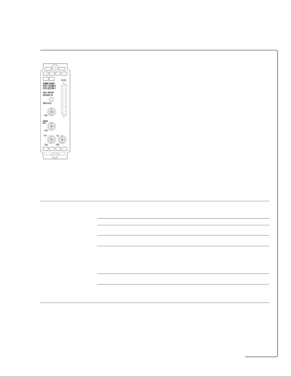
Dual standard SONET/SDH test and interfacing
Option 120
Dual standard SONET/SDH module.
Provides electrical outputs at STS-3/STS-1
and STM-1/STM-0. SONET/SDH optical
interfaces provided when used in
conjunction with option UH1 (page 29)
and options 130/131 (page 30).
SONET specifications detailed below.
Please see option A3R for SDH
specification (page 22).
Option 120
STS-3/STS-1 and STM-1e/STM-0e test and interfacing Dual standard
dual standard SONET/SDH
(for SDH specifications see option A3R) testing
OUT and IN ports (used for transmit)
Type Electrical: To ITU-T G.703. ●
Connectors BNC, 75 ohm, unbalanced. ●
Rate 155.52 Mb/s. ●
Line code 155.52 Mb/s: CMI. ●
Output level 155.52 Mb/s: ± 0.5 V ± 10%. ●
Error output B3 error output pulse on receipt of STS-1 and STS-3 signals. ●
Simultaneous STS-1 When used in conjunction with the appropriate optical interfaces, ●
and OC-1 transmit STS-1 electrical output signal
Transmitter
Clock timing Internal: All rates. ●
51.84 Mb/s. ●
51.84 Mb/s: B3ZS. ●
51.84 Mb/s: ●
Output level is user configurable.
STS-1 X CON: 1.1 V peak nominal (0 ft).
STS-1 HI: 530 mV peak nominal (450 ft).
STS-1 LOW: 350m V peak nominal (900 ft).
TTL pulse termination 75 ohm or 10 k ohm.
simultaneously with OC-1 optical output signal.
Recovered: From SONET input (CMI or NRZ electrical or optical)
Bits: 1.544Mb/s DS1 timing reference as per TA-TSY-000378 Bantam,
100 ohm nominal, unbalanced
Ext MTS: 64kb/s conforming to ITU-T G.703 , Bantam, 120 ohm, balanced
2 Mb/s conforming to ITU-T G.811, BNC 75 ohm unbalanced,
Bantam 120 ohm balanced.
SONET/SDH
120
34
Page 35

STS-3/STS-1 and STM-1e/STM-0e test and interfacing (continued) Dual standard
(for SDH specifications see option A3R) testing
Frequency offset Up to ± 999 ppm in 0.1 ppm steps. ●
generation
Error addition ●
Error type Single Rate 10
Frame A1A2 ● N in four
CV-S (B1) ● 4 to 9
CV-L (B2)† ● 3 to 9
REI-L ● 3 to 9
STS SPE CV-P (B3) ● 4 to 9
STS SPE REI-P ● 4 to 9
STSc SPE IEC-P ● 4 to 9
VT6 CV-V (V5) ● 4 to 9
VT6 REI-V ● 5 to 9
VT2 CV-V (V5) ● 3 to 9
VT2 REI-V ● 4 to 9
VT1.5 CV-V ● 3 to 9
VT1.5 REI-V ● 4 to 9
Bit error* ● 3 to 9
-N
Comments
frame words
SONET/SDH
120
dual standard SONET/SDH
Alarm generation LOS, LOF, SEF, AIS-L, RDI-L. ●
† APS threshold N errors in T ms where 0 ≤ N ≤ 1920 (STM-3) and 10 ms ≤ T ≤ 10000 s,
in decade steps.
*For SONET stand-alone operation, bulk-filled payloads and DS1, DS3 mapped payloads only.
For bit error rates supported with other payloads refer to the DSn/PDH test option for details.
STS SPE AIS-P, STS SPE RDI-P, STS SPE LOP, STS SPE path unequipped.
VT6 path AIS, VT6 RDI-V, VT6 LOP, VT6 path unequipped, VT6 H4 LOM (loss of multiframe).
VT2 path AIS, VT2 RDI-V, VT2 LOP, VT2 path unequipped, VT2 H4 LOM (loss of multiframe).
VT1.5 path AIS, VT1.5 RDI-V, VT1.5 LOP, VT1.5 path unequipped, VT1.5 H4 LOM (loss of multiframe).
Payload capability
Payload mappings (to Bellcore GR-253-CORE)
OC-12/OC-12c/OC-3/OC-3c/OC-1 capability when optical module fitted.
DS3(44.736 Mb/s) into STS-1 SPE† and STS-1 SPE bulk filled mappings: ●
DS1(1.544Mb/s) async into VT1.5†.
139.264 Mb/s into a STS-3c SPE and STS-3c SPE bulk-filled mappings.
2.048 Mb/s (async and fl. byte sync) into VT2 SPE and VT2 SPE bulk filled mappings:
34.368 Mb/s, into STS-1 SPE and STS-1 SPE bulk filled mappings:
VT6 SPE bulk filled mapping and VT6 -Nc (for N = 2 to 6):
† DS1, DS3 mappings require DSn/PDH option UKJ, UKN or 110 to be fitted.
35
Page 36

STS-3/STS-1 and STM-1e/STM-0e test and interfacing (continued) Dual standard
(for SDH specifications see option A3R) testing
SONET/SDH
120
Payload data The following unframed patterns can be generated:
Payload framing 139.264, 34.368 and 2.048 Mb/s: Unframed. ●
Drop/insert 139.264Mb/s: Drop/insert via Tx/Rx on options UKJ/UKN. ●
(Framed and structured signals are available in conjunction
with the PDH/DSn options UKJ/UKN/110).
PRBS: 29 − 1 (O.150), 2
20
QRSS (2
Word: User-defined 16-bit word, all ones, all zeros, 1010, 1000.
All PRBS patterns can be set to be inverted or non-inverted.
† Applicable to DS1 mappings only.
139.264, 34.368 and 2.048 Mb/s: Framed and structured signals†
DS3 payloads: Unframed, C-Bit parity (to ANSI T1.107a-1990)
M13 (to ANSI T1.107-1988)†.
VT6 : Unframed.
DS1 payloads: Unframed, SF (D4), ESF (to ANSI T1.403-1989,
TR-TSY-000499 and ITU-T G.704), SLC-96†.
† Only available in conjunction with the PDH/DSn option UKJ/UKN/110.
44.736 (DS3): Drop/insert via Tx/Rx on option 110.
34.368 Mb/s: Drop/insert via Tx/Rx on options UKJ/UKN/110.
2.048 Mb/s: Drop/insert via drop/insert ports on options UKJ/UKN/110.
1.544 Mb/s (DS1): Drop/insert via drop/insert ports on option 110.
− 1, 14 zero limited)†
11
− 1 (O.152), 2
15
− 1 (O.151) and 2
23
− 1 (O.151) ●
dual standard SONET/SDH
Pointer adjustment generation
Increment/decrement/ Provides a burst, selectable between 1 and 10 pointer ●
alternating adjustments (between 1 and 5 for VT6, VT2 and VT1.5 pointer).
New pointer value The STS SPE, VT6, VT2 or VT1.5 moves to a selectable new ●
Frequency offset Pointer sequences are generated by offsetting the frequencies ●
(and 87:3) of the SPE, (in this mode the 87:3 sequence is generated to
Bellcore GR-253-CORE Bursts of periodic single adjustments with added or canceled ●
and ANSI T1.105.03 adjustments. Polarity is selectable.
location in a single jump, with or without an accompanying
new data flag (NDF).
Bellcore GR-253-CORE/ANSI T1.105.03) or VT6, VT2, VT1.5
and the line rate relative to each other.
Range: ± 100 ppm in 0.1 ppm steps.
Bursts of periodic double adjustments with pairs alternating in polarity.
In all cases the interval between adjustments or pairs of adjustments
is programmable.
On starting to run any of the pointer sequences an initialisation
sequenced followed by a cool down period may be run prior to running
the chosen sequence.
Transmit overhead
Overhead Default selection: Standard overhead values to Bellcore GR-253-CORE . ●
and ANSI T1.05
STS-3/STS-1 TOH can be set in binary or HEX. ●
user-settable bytes SOH: A1, A2, J0, E1, F1, D1 to D3.
J0 path trace: User-defined/predefined 16-byte ITU-T E.164 sequence.
LOH: K1, K2, D4 to D12, S1, M1, E2 (and access to bytes reserved
for national use plus all unmarked bytes reserved for future
international standardization).
STS SPE POH: J1, C2, G1, F2, H4, Z3, Z4 ,N1. ●
J1 path trace: User-defined/predefined 16-byte ITU-T E.164 sequence
or 64-byte sequence.
VT6 SPE , VT2 SPE, VT1.5 SPE POH: V5, J2, Z6, Z7. ●
J2 path trace: User defined/predefined 16-byte ITU-T E.164 sequence.
36
Page 37

STS-3/STS-1 and STM-1e/STM-0e test and interfacing (continued) Dual standard
(for SDH specifications see option A3R) testing
Overhead sequence A single or multi-byte overhead channel is overwritten with ●
generation a single or repeated sequence of programmed values.
Overhead BER test Any SOH, LOH or POH (except A1, A2, H1, H2, Z1, Z2) ●
APS message Messages are displayed in text form as per Bellcore GR-253-CORE for linear ●
generation architecture and to Bellcore GR-1230-CORE for ring architectures (BLSR).
dual standard SONET/SDH
DCC drop/insert The data supplied to the DCC port can be inserted into either ●
Optical interface 2 to 259 bytes of the payload are overwritten with a block ●
stress test of zeros or ones after scrambling.
Tributary scan Automatically test BER on each SONET tributary for error free operation. ●
Mixed payloads Mixed payloads: Each STS-1 SPE within an STS-3 can be independently configured ●
Keep alive signals DSn/PDH:Transmit last configured SONET signal while transmitting ●
The sequence can contain up to five different values each
being transmitted for up to 64,000 frames.
SOH:
6-byte channel A1A2
3-byte channel D1 to D3
Single byte channels: C1, E1, F1.
LOH:
9-byte channel D4 to D12
2-byte channel K1K2
Single byte channels: S1, M1, Z1†, Z2†, E2.
† Z1 and Z2 are not present in STS-1 mode.
High order POH:
Single byte channels: J1, C2, G1, F2, H4, Z3, Z4, N1.
channel is selected and a BER measurement is performed
using a 29 − 1 PRBS inserted into a 64 kb/s channel.
Single errors can be added to the test pattern.
User programmed sequences (K1/K2).
the regenerator section or multiplexer section data
communications channel. Similarly, data can be dropped
from either channel. The data may be dropped/inserted
MSB or LSB first. The data rate for access is: 192 kb/s (SOH DCC),
576 kb/s (LOH DCC).
Alternatively the ITU-T G.958 CID (consecutive identical digits)
test can be selected.
Rx setup is used to determine tributary structure and test pattern.
Alarms: Pattern loss.
Test time: Fully user selectable.
User selectable bit error threshold: Off, > 0, ≥ 10−3, ≥ 10−6.
to contain a STS-1 SPE user word, VT2 or VT1.5 structure.
a DSn/PDH signal.
SONET/SDH
120
Thru mode
Transparent The signal is passed through the instrument without being altered for ●
thru mode monitoring purposes where no protected monitor point is available.
Overhead overwrite In addition to the above, the test features associated with the ●
thru mode TOH and POH can be enabled to control one single- or
multi-byte overhead channel (ie, errors and alarms, optical
stress test, overhead sequences, APS messages, DCC insert,
overhead BER. Full Rx functionality also available).
37
Page 38

STS-3/STS-1 and STM-1e/STM-0e test and interfacing (continued) Dual standard
(for SDH specifications see option A3R) testing
STS-3c/STS-1 SPE In addition to both of the above, overwrite the complete SPE ●
overwrite thru mode with the internally generated payload. This enables the TOH
Tributary overwrite When the payload passing through the instrument contains ●
thru mode a VT structure, thru mode it will be possible to choose a single
to be looped through while a new payload is inserted.
All of the test features which affect the SPE and/or the
POH are enabled (ie, errors and alarms, adjust pointer,
overhead sequences, APS messages, overhead BER. Full Rx
functionality also available).
VT to be overwritten, as opposed to the complete payload.
All of the test features which affect the VT and/or the POH
are enabled (ie, errors and alarms, adjust pointer.
Full Rx functionality also available).
STS-3 and STS-1 receiver functions
STS-3 receive input
Equalization Automatic for cable loss up to 12 dB at half the bit rate. ●
Monitor point Monitor mode conforms to ITU-T G.772. ●
compensation Monitor gain. 20 to 26 dB
dual standard SONET/SDH
STS-1 receive input
Operating level Receiver mode is user selectable. ●
Monitor point Monitor mode conforms to ITU-T G.772. ●
compensation Monitor gain. 20 to 26 dB
STS-1 HI: 1.1 V peak nominal, equalization up to 450 ft
STS-1 LOW: 1.1 V peak nominal, equalization from 450 to 900 ft
SONET/SDH
120
Results
Error results Frame (A1A2), B1, B2, REI-L, ●
DS1/DS3 error results Frame error, CRC6 error (DS1 ESF), P-bit parity (DS3), ●
Error analysis To ITU-T G.826 (G.821 and M.2100/2110/2120 for PDH payload). ●
Alarm indication LOS, LOF, SEF, AIS-L, RDI-L, K1/K2 change ●
Alarm seconds As for alarm indication, plus NDF, missing NDF and except clock loss. ●
STS-3c SPE CV-P (B3), STS SPE REI-L, STS SPE IEC-P.
VT6 CV-V (V5), VT6 REI-V, VT2 CV-V (V5),VT2 REI-V,
VT1.5 CV-V (V5),VT1.5 REI-V, bit errors (bulk filled, DSn/PDH payload).
C-bit parity (DS3 CBP framing), FEBE (DS3 CBP framing).
Bit errors (DS1 and DS3).
STS-1 SPE path AIS, STS-1 SPE RDI-P, STS-1 SPE LOP, STS-1 SPE pointer adj
VT6 path AIS, VT6 RDI-V, VT6 LOP, VT6 pointer adj
VT2 path AIS, VT2 RDI-V, VT2 LOP, VT2 pointer adj
VT1.5 path AIS, VT1.5 RDI-V, VT1.5 LOP, VT1.5 pointer adj
H4 multiframe sync loss, pattern sync loss, clock loss, power loss
and errors (any type).
DS1/DS3 alarm indication: AIS, frame loss, RDI. ●
38
Page 39

STS-3/STS-1 and STM-1e/STM-0e test and interfacing (continued) Dual standard
(for SDH specifications see option A3R) testing
AlarmScan plus Automatically scans the SONET network hierarchy for alarms ●
alarm and BIP scan and BIP errors or alarms only with a graphical display of the network
Protection switch times Service disruption test measures error burst length for ●
Pointer results STS Path pointer value, NDF-P seconds, STS Path missing pointer, NDF seconds, ●
dual standard SONET/SDH
Frequency Frequency displayed in Hz, 1 Hz resolution. ●
measurement Offset displayed in ppm and Hz.
Received overhead TOH can be set in binary or HEX. ●
snapshot TOH and POH of a received STS-3 signal.
Overhead sequence Any one overhead channel is selected. After a manual or programmed ●
capture trigger, the captured byte values are displayed together with the
Pointer A graphical display that shows the variation with time of the ●
location graph STS Path and VT pointer location. Up to four days of pointer location
Overhead BER Any SOH, LOH or POH (except A1, A2, H1, H2, Z1, Z2) ●
measurement channel is selected and a BER measurement is performed
hierarchy’s status including the indication of unequipped channels.
Alarms: LOP, path AIS, RDI-P, H4 LOM†, VT LOP*, AIS-V*, RDI-V.*
† For VT6 , VT2 AND VT1.5 structures.
* If applicable.
BIP errors:
STS SPE payloads: STS SPE CV-P (B3).
VT6 /VT2 /VT1.5 payloads: STS-3c SPE/STS-1 SPE B3 and CV-V (V5).
User selectable BIP error threshold: Off, > 0, > 10−3, > 10−6.
measurement of protection switch times†.
Accuracy: < 50 µs.
Results: Longest burst length, shortest burst length, last burst length.
Resolution: 1 µs.
† Service disruption test requires PDH/DSn option UKJ, UKN or 110 to be fitted.
STS Path +ve adjustment count/seconds, STS Path −ve adjustment count/seconds,
VT pointer value, NDF-V seconds, VT pointer missing NDF -V seconds,
VT+ve adjustment count/seconds, VT−ve adjustment count/seconds,
implied STS-3c SPE, STS-1 SPE, VT6 SPE , VT2 SPE offset.
TOH and POH of a received STS-1 signal.
Text message displayed for signal label (C2 and V5) and sync status
(S1) decoded.
number of consecutive frames containing the value.
activity can be monitored.
Implied SPE offset: The total positive and negative pointer
movements since the start of the measurement period are summed
and the implied mean SPE offset calculated from this total.
using a 29 − 1 PRBS inserted into a 64 kb/s channel. Single errors can
be added to the test pattern. Error count, error ratio, error free seconds,
% error free seconds and pattern loss seconds are measured.
SONET/SDH
120
39
Page 40

Jitter generation
Option 140
PDH jitter generation: 2, 8, 34 and
140 Mb/s up to 80 UI (2 Mb/s).
SDH jitter generation: STM-1
(155 Mb/s) and STM-4 (622 Mb/s)
up to 200 UI (STM-4).
Option A3K
All the capability of option 140 plus
wander generation: 2 Mb/s, STM-1
(155 Mb/s) and STM-4 (622 Mb/s)
up to 14400 UI (STM-4).
Option A3K
Option 140
Jitter generation option† SDH and PDH
PDH jitter generation requires a PDH test option (UKK, UKJ or UKN) to be fitted.
SDH jitter generation requires an STM-1 test option (A3R, 120 or A1T) to be fitted. A3K 140
OUT and IN ports (used for transmit and receive)
Connectors PDH jitter generation uses the Tx ports on the PDH option ● ●
jitter generation and measurement
Rate 2.048, 8.448, 34.368 and 139.264 Mb/s if appropriate PDH option fitted. ●●
Other ports External jitter modulation input (75 ohm, unbalanced). ●●
(UKK, UKJ, UKN or UH3).
SDH jitter generation uses the electrical Tx ports on the STM-1 test option (A1T, 120 or A3R)
or the Tx ports on the optical interfacing STM-1/STM-4 (UH1, USN, UKT, 130, 131 or 0YH).
155.52 Mb/s (STM-1) and 622.08 Mb/s (STM-4) if appropriate SDH and optical
interface options fitted.
Ext MTS: Data or clock format (as ITU-T G.811). ●●
Jitter modulation
Frequency 0.1 Hz to 5 MHz. ●●
Frequency accuracy ± 1% above 3 Hz, ± 3% below 3 Hz. ●●
Frequency resolution 1 Hz for 1 and 10 UI ranges steps. ●●
† NB: Jitter generation can be used simultaneously with frequency offset.
0.1 Hz for 50, 80 and 200 UI ranges.
jitter generation
40
Page 41
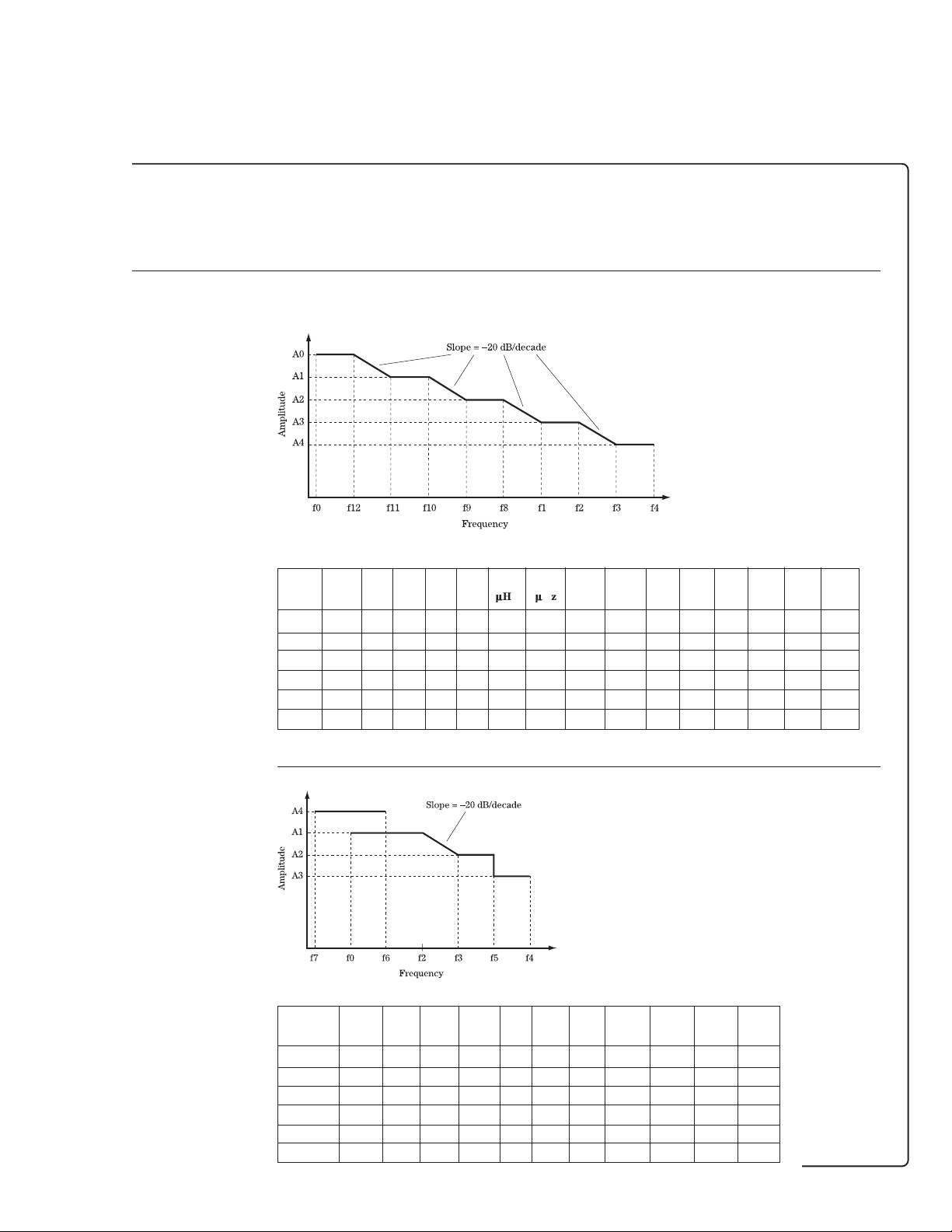
Jitter generation option (continued) SDH and PDH
jitter generation
A3K 140
ITU-T 0.171 Meets and exceeds the requirements of ITU-T G.825, G.958 and G.823. ●●
specification
Meets the following ITU-T O.171 jitter amplitude versus modulation frequency specification.
Bit rate A0 A1 A2 A3 A4 F0 F12 F11 F10 F9 F8 F1 F2 F3 F4
(kb/s) (UI) (UI) (UI) (UI) (UI) (mHz) (mHz) (mHz) (mHz) (Hz) (Hz) (Hz) (Hz) (Hz) (Hz)
2,048 40 - 20 10 0.5 12 - - - - 5 10 900 18k 100k
8,448 - - - 10 0.5 - - - - - 10 20 400 8.5k 400k
34,368 - - - 10 0.5 - - - - - 50 100 1.0k 20k 800k
139,264 - - - 10 0.5 - - - - - 50 100 500 10k 3.5M
155,520 3,600 400 50 2 0.2 12 178 1.6 15.6 0.125 100 500 6.5k 65k 1.3M
622,080 14,400 1,600 200 2 0.2 12 178 1.6 15.6 0.125 9.65 1k 25k 250k 5.0M
The actual corner frequencies of the jitter generator will be beyond those in the ITU-T mask.
jitter generation and measurement
Jitter amplitude ● ●
versus modulation
Bit rate A4 A1 A2 A3 F7 F0 F6 F2 F3 F5 F4
(kb/s) (UI) (UI) (UI) (UI) (Hz) (Hz) (Hz) (kHz) (kHz) (kHz) (kHz)
2,048 80 10 1 0.6 0.1 2 100 13 25 50 102
8,448 10 1 0.6 - 2 - 50 100 200 430
34,368 10 1 0.6 - 2 - 100 200 400 840
139,264 10 1 0.6 - 2 - 5 10 2,000 4,000
155,520 50 5 1 0.6 0.1 2 500 5 50 1,000 4,000
622,080 200 5 2 1.2 0.1 2 500 5 50 1,000 5,000
41
Page 42

Jitter generation option (continued) SDH and PDH
jitter generation
A3K 140
Amplitude To ITU-T O.171. ●●
Jitter amplitude range ●●
Range Min. UI Max. UI Step size
1 0. 01 1. 00 0.01
10 0.1 10. 0 0.1
80 0.5 80. 0 0.5
50 0.5 50. 0 0.5
200 0.5 200. 0 0. 5
Jitter amplitude ± 5% ± X ± Y (± Z at STM-1e only), ● ●
accuracy where X is the amplitude accuracy given in the table below:
Amplitude accuracy
Range X (UI)
1 0.01
10 0.1
80 1
50 0.5
200 2
where Y is the Generator intrinsic jitter given in the table below:
Generator intrinsic jitter
Bit rate
(kb/s) Y (UI)
jitter generation and measurement
2,048 0.02
8,448 0.02
34,368 0.03
139,264 <10 kHz 0.04
>10 kHz 0.02
155,520 <10 kHz 0.04
>10 kHz 0.03
622,280 0. 10
(UI)
where Z is the additional STM-1e high frequency accuracy1 shown in the table below:
Interface Selected jitter Z (UI)
STM-1e > 1.3 MHz and 10%
STM-1e > 1.3 MHz and 20%
All other rates All 0
and interfaces
1
The high frequency accuracy factor only applies outwith the ITU-T O.171
specified modulation frequency range.
Values are peak-to-peak jitter in UI measured with HP1 filter present
frequency and nominal
amplitude
< 0.2 UI
> 0.2 UI
42
Page 43

Jitter generation option (continued) SDH and PDH
jitter generation
A3K 140
Tolerance masks Four fixed jitter tolerance masks with peak-to-peak jitter amplitudes and ● ●
Automatic jitter The mask is swept in frequency increments and at each frequency the jitter ● ●
tolerance amplitude is increased until errors (of any type) are detected.
Number of 3 to 55 in steps of 1. Step sizes calculated as follows ● ●
frequency points
Dwell time 0.1 to 99.9 seconds in 0.1 second steps. ●●
Delay time 0.1 to 99.9 seconds in 0.1 second steps. ●●
Bit error threshold Any error or 1 to 106 bit errors in steps of 1. ●●
Jitter tolerance Rate Pass masks Type ●●
results masks
jitter generation and measurement
modulating frequencies to ITU-T G.823 Table 2 covering low and high Q systems.
The masks can be used to measure tolerance to jitter amplitude at spot jitter
frequencies or can be swept in 20% frequency increments.
When generating an SDH signal, the masks available are those specified in
ITU-T G.958. A choice of type A or B masks is available at STM-1 and STM-4.
log (f
) – log (f
log (m) =
n = Number of frequency steps
m = Multiplier applied to the frequency to determine the next frequency value.
For 55 steps, the multiplier is +20%. For 10 steps, the multiplier is +200%.
Time spent at each amplitude point/frequency point waiting for error events.
Time spent at each amplitude/frequency point waiting for the system under
test to settle before performing the measurement.
Any error allows jitter tolerance testing using the “Onset of Errors Technique”
The bit error threshold allows the instrument to record a pass at a particular point when
the bit error count is non-zero and allows the instrument to make measurements using the
“1 dB Power Penalty Technique”
2 Mb/s ITU-T G.823 Low Q and high Q
8 Mb/s ITU-T G.823 Low Q and high Q
34 Mb/s ITU-T G.823
140 Mb/s ITU-T G.823
STM-1 ITU-T G.958 Type A and type B
STM-4 ITU-T G.958 Type A and type B
max
(n – 1)
)
min
43
Page 44

Jitter generation option (continued) SDH and PDH
jitter generation
A3K 140
Wander modulation
External MTS Data or clock format (as ITU-T G.811). ●
clock input BNC, 75 ohm, unbalanced or Siemens (3-pin) 120 ohm balanced. –
Frequency 10 µHz to 0.125 Hz. ● –
Frequency accuracy ± 1%. ● –
Frequency resolution 1 µHz. ● –
Wander amplitude Generated wander amplitude versus modulation frequency ● –
versus modulation
frequency’ Bit rate A0 A1 F0 F11 F9
(kb/s) (UI) (UI) (µHz) (mHz) (Hz)
2,048 80 80 10 - 0.125
155,520 3,600 400 10 1.6 0.125
622,080 14,400 1,600 10 1.6 0.125
Meets or exceeds the ITU-T O.171 specification.
Wander amplitude ● –
jitter generation and measurement
range Bit rate Minimum Maximum Step size
Wander amplitude ± 5% ± X ± Y. ● –
accuracy
Fixed wander A pre-programmed wander tolerance mask to ITU-T G.823 Table 2 and ITU-T G.958 ● –
tolerance mask can be selected to automatically control the wander amplitude. The analyzer will
(kb/s) (UI) (UI) (UI)
2,048 0.5 80 0.5
155,520 0.5 3,600 0.5
622,080 0.5 14,400 0.5
Bit rate X Y
(kb/s) (UI) (UI)
2,048 1 0.1
155,520 0.5 0.1
622,080 0.5 0.1
automatically select the appropriate amplitude for the selected frequency.
Bit rate A0 A1 A2 F0 F12 F11 F10 F9
(kb/s) (UI) (UI) (UI) (µHz) (mHz) (mHz) (Hz) (Hz)
2,048 36.9 18 1.5 12 4.88 m 10 m 0.125 -
155,520 2,800 311 39 12 178 µ 1.6 m 15.6 m 0.125
622,080 11,200 1,244 156 12 178 µ 1.6 m 15.6 m 0.125
44
Page 45

Jitter measurement
JITTER RECEIVER
2M REF IN
120Ω
DEMOD
OUT
75Ω
75Ω
STM-1E
75Ω
IN
Option A3L
JITTER RECEIVER
2M REF IN
120Ω
DEMOD
OUT
75Ω
75Ω
STM-1E
IN
STM-1
IN
75Ω
Option A3V
JITTER RECEIVER
2M REF IN
120Ω
DEMOD
OUT
75Ω
75Ω
STM-1E
IN
STM-1/STM-4
IN
Option A3NOption UHN
Option UHN
PDH jitter measurement: 2, 8, 34
and 140 Mb/s electrical interface.
Option A3L
STM-1e line and PDH jitter
measurement: 2, 8, 34, 140 and
155 Mb/s.
Option A3V
STM-1o, STM-1e line and PDH
75Ω
jitter measurement: 2, 8, 34,
140 Mb/s electrical and 155 Mb/s
electrical and optical.
Option A3N
STM-4o, STM-1o, STM-1e line and
PDH jitter measurement: 2, 8, 34,
140 Mb/s electrical, 155 Mb/s
electrical and optical and
622 Mb/s optical.
Jitter measurement test options PDH jitter STM-1e STM-1o, STM-4o,
and STM-1e STM-1o,
PDH jitter and STM-1e
Requires a PDH test option (UKK, UKJ or UKN)
for PDH jitter measurement. UHN A3L A3V A3N
OUT and IN ports (used for transmit and receive)
Type Electrical SDH: To ITU-T G.703. – ●●●
Connectors Uses the Rx ports on the PDH option (UKK, UKJ or UKN) ●●●●
jitter generation and measurement
Other ports External MTS clock input (75 ohm unbalanced, ●●●●
Optical. – – ●●
or the Rx clock port on the PDH binary option UH3 for
PDH jitter measurement.
STM-1e jitter measurement uses BNC, 75 ohm, unbalanced. – ●●●
(Small Siemens 75 ohm unbalanced option available.)
STM-1o, STM-4o customer exchangeable optical adaptors – – ●●
allow a range of interfaces to be attached.
120 ohm balanced).
Demodulated jitter output (75 ohm, unbalanced). ●●●●
Receiver
Rate 2.048, 8.448, 34.368 and 139.264 Mb/s. ●‡ ● ‡ ● ‡ ● ‡
PDH input Refer to PDH test option UKK, UKJ, UKN or UKZ. ●●●●
Detector type MLM (multi mode).* – ●●●
STM-1e input Line code: CMI. – ●●●
STM-1e (155 Mb/s electrical). – ●●●
STM-1o (155 Mb/s optical). – – ●●
STM-4o (622 Mb/s optical). – – – ●
‡ PDH jitter measurement uses Rx ports on PDH module.
Impedance: 75 ohm.
Equalization: Automatic for cable loss up to 12 dB
at half the bit rate.
Monitor: 20 to 26 dB of flat gain.
PDH jitter and
PDH jitter
* MLM receivers work with both MLM (multi mode) and SLM (single mode) transmitters.
45
Page 46

Jitter measurement test options (continued) PDH jitter STM-1e STM-1o, STM-4o,
and STM-1e STM-1o,
PDH jitter and STM-1e
UHN A3L A3V A3N
PDH jitter and
PDH jitter
STM-1o input Line code: NRZ. – – ●●
STM-4o input Line code: NRZ. – – – ●
Wavelength: 1200 to 1600 nm.
Sensitivity: −28 dBm minimum.
Using 1300 nm wavelength, 100% modulation depth
and BER of 10
Dynamic range: 20 dB minimum.
Maximum input power: −8 dBm.
Wavelength: 1200 to 1600 nm.
Sensitivity: −26 dBm minimum.
Using 1300 nm wavelength, 100% modulation depth
and BER of 10
Dynamic range: 18 dB minimum.
Maximum input power: −8 dBm.
−10
and PRBS of 223 − 1.
−10
and PRBS of 223 − 1.
SDH-PDH jitter transfer
Automatic jitter Automatic jitter transfer test at 2, 8, 34, 139 Mb/s, STM-1e, STM-1o– ●●●
transfer or STM-4o. Narrow band selective filtering is performed in
Number of 1 to 55 in steps of 1. – ●●●
frequency NB When a single point is selected, no graph is available.
points Only text results will be displayed.
jitter generation and measurement
Delay time 5 to 30 seconds in 1 second steps. – ●●●
Dwell time 5 to 30 seconds in 1 second steps. – ●●●
Jitter transfer Select between ITU-T defined fixed mask or user selectable – ●●●
input mask input mask.
the receiver. Jitter transfer results are plotted graphically
alongside the relevant ITU-T mask.
Step sizes calculated as follows
log (f
) – log (f
log (m) = ___________________
n = Number of frequency steps
m = Multiplier applied to the frequency to determine the next
frequency value.
For 55 steps, the multiplier is +20%.
For 10 steps, the multiplier is +200%.
Time spent at each amplitude point/frequency point waiting for
the system under test to settle before performing the measurement.
During calibration, the delay time used is fixed at 5 sec.
Test period time spent at each amplitude/frequency point.
The result recorded is the maximum peak-to-peak jitter amplitude
detected during the dwell time test period.
max
(n – 1)
min
)
46
Page 47

Jitter measurement test options (continued) PDH jitter STM-1e STM-1o, STM-4o,
and STM-1e STM-1o,
PDH jitter and STM-1e
UHN A3L A3V A3N
Fixed jitter
transfer input Bit – ●●●
masks rate Mask F1 F2 F3 F4 A1 A2
(Mb/s) (Hz) (Hz) (Hz) (Hz) (UI) (UI)
2 Mb/s G.823, High Q 20 2.4 k 18 k 100 k 1.5 0.2
8 Mb/s G.823, High Q 20 400 3 k 400 k 1.5 0.2
34 Mb/s G.823 100 1 k 10 k 800 k 1.5 0.15
140 Mb/s G.823 200 500 10 k 3500 k 1.5 0.08
STM-1 G.958, Type A
STM-4 G.958, Type A
G.823, Low Q 20 93 700 100 k 1.5 0.2
G.823, Low Q 20 10.7 k 80 k 400 k 1.5 0.2
G.958, Type B 500 16 .5 k 65 k 1300 k21.5 0.15
G.958, Type B 1 k125 k 250 k 5000 k
2,3
1.5 0.15
User selectable F1 < F2 < F3 < F4 – ●●●
jitter transfer F1
input mask A1
= 15 Hz, F4
min
= max value that can be generated at F2.
max
A2
= max value that can be generated at F4.
max
Note: The maximum value that can be generated is as defined by
= F4 in ITU-T O.171 Table 3.
max
ITU-T O.171 Table 3 (shown in jitter and wander generation section
except for 8 Mb/s where F2
is enabled, the ITU-T pass mask can also be displayed along
= 10.7 kHz. When user selectable
max
with the results.
Jitter transfer 10 Hz. – ●●●
measurement
bandwidth
Jitter transfer +5 dB to −40 dB. – ●●●
dynamic range
Jitter transfer 0.02 dB. – ●●●
stability Measurements must be completed within 10 mins of the
completion of the calibration cycle.
Jitter transfer 0.01 dB. – ●●●
jitter generation and measurement
calibration
Jitter transfer Figures quoted below include stability and calibration factors. – ●●●
accuracy
Rx jitter amplitude Accuracy
(UI) (dB)
PDH jitter and
PDH jitter
3 to 0.3 0.04
0.3 to 0.03 0.25
0.03 to 0.01 0.5
0.01 to 0.003 1
0.003 to 0.001 3
The accuracy figures were verified using the following patterns,
PDH: Unframed 1000, unframed default PRBS (refer to UKJ specification).
STM-1, STM-4: VC-4 containing unframed 140 Mb/s at 223 − 1.
47
Page 48
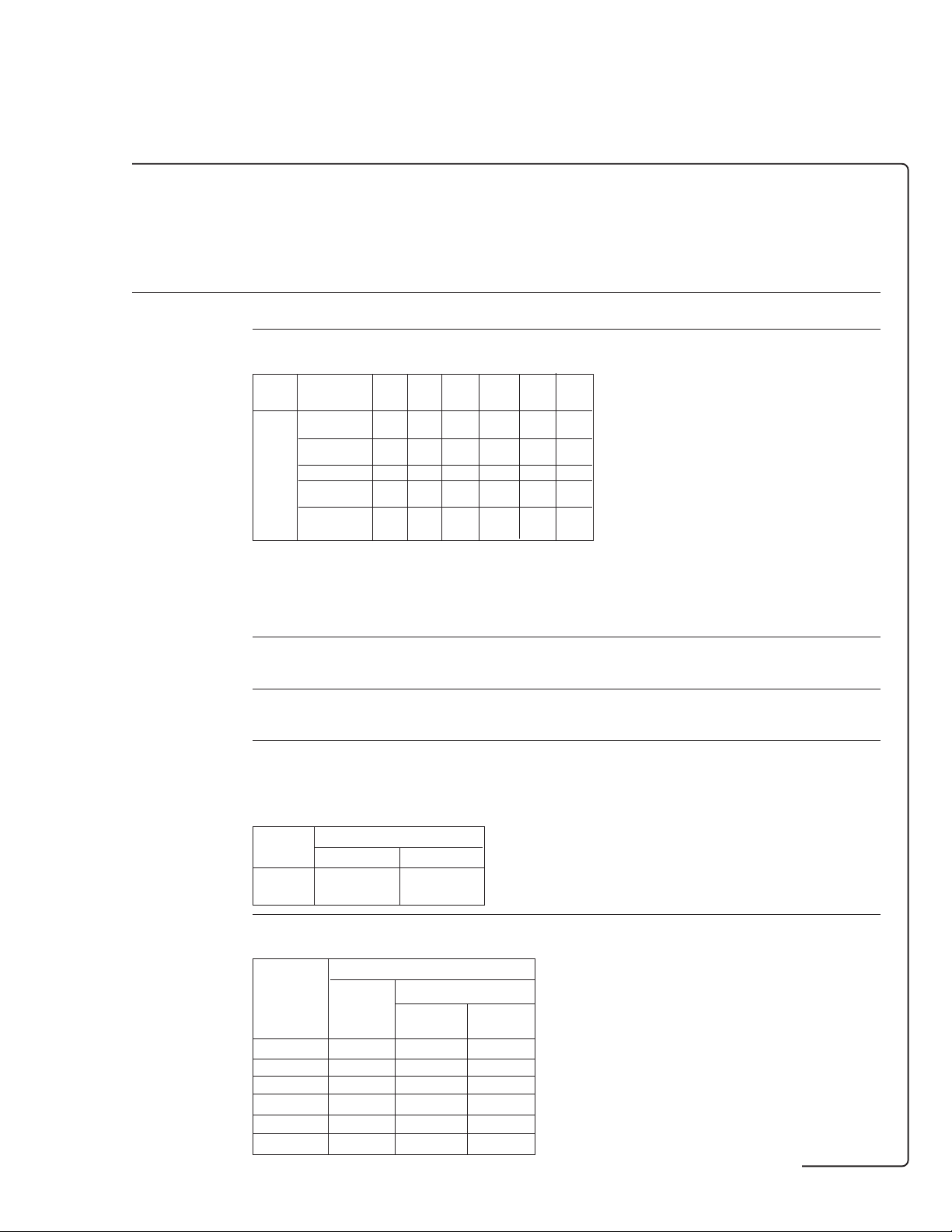
Jitter measurement test options (continued) PDH jitter STM-1e STM-1o, STM-4o,
and STM-1e STM-1o,
PDH jitter and STM-1e
UHN A3L A3V A3N
PDH jitter and
PDH jitter
Jitter transfer Tabular or graphical form – ●●●
Jitter transfer Results will be compared to ITU-T pass mask
pass mask specified in the appropriate standard.
Jitter transfer The result is plotted alongside the pass mask on a graph of – ●●●
graphical results gain versus frequency. The y-axis range is selectable as
Jitter transfer The result will be displayed in a table, with the following – ●●●
tabular results information displayed for each result: Point number, frequency,
results
Bit
rate Mask F1 F2 F3 F4 A1 A2 – ●●●
(Mb/s) (Hz) (Hz) (Hz) (Hz) (UI) (UI)
2 Mb/s G.8231 High Q 20 40 400 100 k 0.5 −19.5
G.8231 Low Q 20 70 700 100 k 0.5 −19.5
8 Mb/s G.8232 High Q 20 100 1 k 400 k 0.5 −19.5
G.8232 Low Q 20 8 k 80 k 400 k 0.5 −19.5
34 Mb/s G.823
STM-1 G.958, Type A 130 k Note b – 0.1 –
STM-4 G.958, Type A 1 k 500 k Note b – 0.1 –
1
Actual values from ITU-T G.742.
2
Actual values from ITU-T G.751.
Note
(a) No mask is defined in the ITU-T standards for 139 Mb/s.
In this case, the display will show the result without the pass threshold being indicated.
(b) The mask shows threshold falling off by 20 dB per decade after F2.
+5 dB to −60 dB or +3 dB to −3 dB.
mask value, result, pass fail indication.
2
100 300 3 k 800 k 0.5 −19.5
G.958, Type B 500 30 k – 0.1 –
G.958, Type B 1 k 30 k – 0.1 –
Peak-peak jitter measurement
jitter generation and measurement
Jitter These ranges cope with the measurements required in ●●●●
measurement ITU-T O.171 Table 3.
ranges
Range Lower UI Upper UI
1.6 0 1.6
16 0 16
Peak-to-peak To ITU-T O.171 Table 4. ●●●●
jitter
measurement
bandwidth Receiver bandwidth
Bit rate Min Max
(kb/s)
2,048 2 Hz 100 kHz 50 kHz
8,448 2 Hz 400 kHz 100 kHz
34,368 2 Hz 800 kHz 400 kHz
139,264 2 Hz 3.5 MHz 800 kHz
155,520 2 Hz 1.3 MHz 800 kHz
622,080 2 Hz 5.0 MHz 800 kHz
Receiver range
Range Range
1.6 UI 16 UI
48
Page 49

Jitter measurement test options (continued) PDH jitter STM-1e STM-1o, STM-4o,
and STM-1e STM-1o,
PDH jitter and STM-1e
UHN A3L A3V A3N
Peak ●●●●
measurement To ITU-T O.171
accuracy
Range Accuracy Accuracy
(UI) (peak) (peak-to-peak)
1.6 ± 5% ± X ± Y ± 5% ± 2X ± Y
16 ± 5% ± X ± Y ± 5% ± 2X ± Y
Where X is 0.01 UI for 1.6 UI range, 0.03 UI for 16 UI range,
Y is receiver intrinsic jitter detailed below.
Receiver ●●●●
intrinsic jitter
(all rates) 1.6 UI range 16 UI range
PDH jitter and
PDH jitter
jitter generation and measurement
Bit rate Intrinsic
(kb/s) jitter Clock PRBS
YYY
2,048 0.02 0.07 0.1
8,448 0.02 0.07 0.1
34,368 0.02 0.07 0.1
139,264 0.02 0.07 0.1
155,520
(electrical) 0.02 n/a 0.1
155,520
(optical) 0.03 n/a 0.1
622,080
(optical) 0.04 n/a 0.2
1
Typically 0.05 UI after calibration
The following additional intrinsics may apply:
0.01 UI (typical) when using monitor gain.
0.01 UI (typical) when using equalization.
0.01 UI (typical) at STM-1 optical with light levels < −22 dBm.
0.01 UI (typical) at STM-4 with light levels < −16 dBm.
0.02 UI (typical) at STM-4 with light levels < −22 dBm.
0.01 UI (typical) at temperatures outwith ambient.
Values are peak-to-peak jitter in UI measured with HP1 and LP filter present.
Intrinsic jitter (UI)
(all ones)
1
1
1
1
49
Page 50
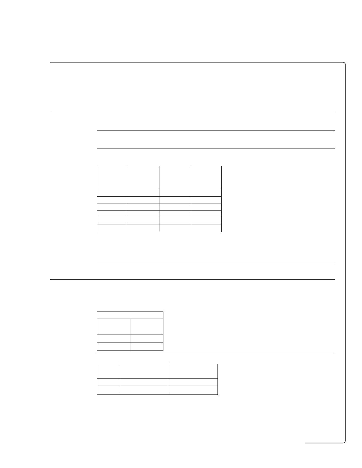
Jitter measurement test options (continued) PDH jitter STM-1e STM-1o, STM-4o,
and STM-1e STM-1o,
PDH jitter and STM-1e
UHN A3L A3V A3N
Jitter peak 1.6 UI range: 0.001 UI; ●●●●
results 16 UI range: 0.01 UI.
resolution
Jitter hit Steps of 0.01 UI (range 1.6); steps of 0.10 UI (range 16). ●●●●
threshold
resolution
Internal filters To ITU-T O.171. ●●●●
Internal filters: Nominal 3 dB corner frequencies.
Filter HP1 HP2 LP
(kb/s) (high pass) (high pass) (low pass)
(Hz) (kHz) (kHz)
2,048 20 18 100
8,448 20 80 400
34,368 100 10 800
139,264 200 10 3,500
155,520 500 65 1,300
622,080 1,000 250 5,000
HP filters: Slope below 3 dB point is 20 dB per decade;
LP filters: Slope above 3 dB point is 60 dB per decade.
Combinations of filters available: Off (no filters), LP only,
HP1 only, HP2 only, LP and HP1, LP and HP2,
12 kHz HP (can be enabled in addition to all of the above or by itself).
Demodulated 1.0 V per UI (range 1.6); 0.1 V per UI (range 16). ●●●●
jitter output
PDH jitter and
PDH jitter
RMS jitter measurement
jitter generation and measurement
RMS jitter The RMS ranges are linked to the selection for peak. – ●●●
measurement No separate selection will exist.
ranges
RMS – ●●●
measurement
accuracy Range Accuracy Additional factor
1.0n 5 UI range: Z (high frequency accuracy) is only applicable at 2 Mb/s rate.
Where V is display resolution: 0.002 UI for 0.5 UI Range, 0.02 UI for 5 UI range.
W is rms receiver intrinsic jitter detailed below.
Z is rms high frequency accuracy detailed below.
Receiver range
Peak range rms range
(UI) (UI)
1.6 0.5
16 5.0
(UI) 20 Hz to 3 MHz > 3 MHz
0.5 ± 5% ± V ± W ± Z ± 5%
5 ± 5% ± V ± W ± Z
1
± 5%
50
Page 51

Jitter measurement test options (continued) PDH jitter STM-1e STM-1o, STM-4o,
and STM-1e STM-1o,
PDH jitter and STM-1e
UHN A3L A3V A3N
RMS receiver – ●●●
intrinsic jitter
(all rates) 0.5 UI range 5 UI range
PDH jitter and
PDH jitter
Bit rate jitter Clock PRBS
(kb/s) (UI) (all ones)
2,048 0.004 0.03 0.04
8,448 0.003 0.03 0.04
34,368 0.02 0.04 0.05
139,264 0.01 0.03 0.04
155520
(electrical) 0.006 n/a 0.04
155520
(optical) 0.015 n/a 0.04
622,080 0.02 n/a 0.08
RMS high – ●●●
frequency
accuracy Bit rate Selected Z
jitter generation and measurement
(kb/s) frequency (UI)
SDH rates all 0
2,048 > 30 kHz (f–30)/70 × 6%
8,448 > 150 kHz (f–150)/250 × 6%
34368
139264
1
Where f is the modulation frequency in kHz.
Intrinsic
WWW
Intrinsic jitter (UI)
1
1
all 0
The following additional intrinsics may apply:
0.004 UI
0.004 UI
0.004 UI
0.004 UI
0.008 UI
0.005 UI
Values are rms jitter in UI
RMS results 0.5 UI range: 0.001 UI rms. – ●●●
resolution 5 UI range: 0.01 UI rms.
(typical) when using monitor gain.
rms
(typical) when using equalization.
rms
(typical) at STM-1o with light levels < −22 dBm.
rms
(typical) at STM-4o with light levels < −16 dBm.
rms
(typical) at STM-4o with light levels < −22 dBm.
rms
(typical) at temperatures outwith ambient.
rms
measured with 12 kHz HP filter present.
rms
51
Page 52

Jitter measurement test options (continued) PDH jitter STM-1e STM-1o, STM-4o,
and STM-1e STM-1o,
PDH jitter and STM-1e
UHN A3L A3V A3N
Jitter results
PDH jitter and
PDH jitter
Results Hits: Jitter hit count, jitter hit seconds, jitter hit-free seconds, ●●●●
Jitter transfer Display results from last auto-jitter transfer measurement. – ●●●
Alarms Loss of signal, jitter unlock and jitter out of range. ●●●●
Graphical results Jitter hit count result plus jitter unlock, jitter out-of-range ●●●●
Amplitude: +ve peak amplitude, -ve peak amplitude,
peak-to-peak amplitude.
Amplitude: rms amplitude. – ●●●
and loss of signal alarms are stored/displayed in SMG
(stored measurement graphics).
Wander measurement
Timing reference Ext. MTS: Data or clock format (as ITU-T G.811). ●●●●
input BNC, 75 ohm, unbalanced or Siemens (3-pin), 120 ohm, balanced.
Wander results +ve peak amplitude, -ve peak amplitude, peak-to-peak ●●●●
Wander alarms No reference and excess wander. If wander > 5 UI in any ●●●●
Bandwidth Low pass response −3 dB at 10 Hz (nominal). ●●●●
jitter generation and measurement
jitter generation and measurement
Resolution 0.125 UI. ●●●●
Range ± 99999 UI. ●●●●
Accuracy ± 0.125 UI ± 0.5% of reading (up to 1 Hz wander frequency). ●●●●
Estimate frame 0 to 9 999 999 frames. ●●●●
slips
Estimate bit 0 to 9 999 999 bits. ●●●●
slips
Implied frequency TIE expressed as a ppm offset to nominal (0 .. 999.99 ppm). ●●●●
offset
Graphical wander Wander measurement presented in graphical form.
amplitude, peak-to-peak amplitude (15 minutes)
peak-to-peak amplitude (24 hours), time interval error, implied
frequency offset, estimated frame slips, estimated bit slips.
All results can be displayed in bits (0..99 999 999.999 bits)
or µs (0..99 999 999.999 µs) except:
Estimated frame slips: 0..9 999 999 frames,
Estimated bit slips: 0..9 999 999 bits,
Implied frequency offset: 0..999.99 ppm.
15 minute period or > 28 UI in any 24 hour period then the
status message “excess wander” is displayed.
Three positive and negative sliding bar graphs each of ± 1 UI,
± 16 UI, ± 256 UI are provided. Bit slips and estimated frame
slip results plus wander reference unlock and excessive wander
alarms are stored/displayed in SMG (stored measurement graphics).
Definitions
Time interval error: Current offset with respect to the position at start of gating displayed with a resolution of 0.125 UI.
Estimated frame slips: Each time a complete UI of wander (+ or –) is accumulated the bit slips count is incremented..
Estimated bit slips: Each time the accumulated movement equals +/– 256 UI (ie, the 2 Mb frame size), the frame slips
count is incremented.
52
Page 53

ATM cell test options
ATM
Option UKN (ETSI only)
Pair of modules providing ATM cell layer
generation and measurement: 2, 34 and
140 Mb/s (includes structured PDH generation
and measurement: 2, 8, 34 and
140 Mb/s – refer to page 12 and 13).
Option UKN
ATM cell test options – ETSI only ATM cell
ATM transmitter
Physical layer
Type Electrical: To ITU-T G.703. ●
Connectors BNC, 75 ohm, unbalanced and Siemens 3-pin, 120 ohm balanced. ●
jitter generation and measurement
Rates 2.048, 34.368, 139.264 and 155.52 Mb/s‡. ●
Frequency offset generation‡ 2.048, 34.368 and 139.264 Mb/s: Up to ± 100 ppm in 1 ppm steps. ●
Clock timing‡ Internal: All rates. ●
Framing 2.048 Mb/s (E1): As per ITU-T G.804/G.704; ●
Transmission convergence 2.048 Mb/s: To ITU-T G.804/G.704 (CRC4 on/off); ●
Error add Single HEC or double HEC; 1 in 103 or single error; HEC error sequences. ●
(Small Siemens 75 ohm unbalanced option available.)
34.368 Mb/s (E3) and 139.264 Mb/s: As per ITU-T G.832;
Error monitoring (EM) contains correct BIP-8;
Trail trace (TR) is user-definable (ITU-T E.164 format);
Maintenance adaptation (MA) is set to 011 (hexadecimal);
Network operator (NR) and general communications (GC) are set to all zeros;
155.520 Mb/s: As per ITU-T G.707‡.
34.368 Mb/s and 139.264 Mb/s: To ITU-T G.804/G.832;
155.52 Mb/s: To ITU-T G.707‡.
generation
and analysis
UKN
‡ For 155.52 Mb/s you also require an STM-1 test option (option A1T or A3R).
53
Page 54

ATM
ATM cell test options – ETSI only (continued) ATM cell
generation
and analysis
UKN
ATM layer
ATM layer interfaces UNI, NNI. ●
Number of foreground 1. ●
virtual channels (VCs)
Foreground VC bandwidth 2.048 Mb/s: 100 to 4,528 cells per second in steps of 1 cell/s; ●
Foreground VC distribution Constant: Single cell is transmitted at regular intervals determined by the cell rate ●
Foreground VC payload Cross cell PRBS (215 − 1, 223 − 1 to ITU-T O.151); ●
Error add (foreground VC) Payload bit errors; 1 in 103 or single error. ●
Number of background VCs Up to 3. ●
Background VC density Individually set from 0 to maximum in 1% steps after foreground allocation. ●
Background VC distribution Constant (for constant bit rate service). ●
Background VC payload User-defined byte repeated to fill cell payload (individually set per background VC). ●
VC priority Foreground VC has top priortity; background VCs have approximately equal priority. ●
Fill cells Idle or unassigned. All bytes of the payload are set to 6AH. ●
34.368 Mb/s: 100 to 80,000 cells per second in steps of 1 cell/s;
139.264 Mb/s: 100 to 326,037 cells per second in steps of 1 cell/s;
155.52 Mb/s:‡ 100 to 353,207 cells per second in steps of 1 cell/s‡.
(cells/s = 100 to max). Also allows a single burst of consecutive cells from
1 to 2048 in steps of 1 cell.
Burst: User-specified burst of up to 2047 consecutive cells added.
Single cell PRBS (29 − 1);
User-defined byte repeated to fill cell payload (48 bytes);
Test cell (to draft ITU-T O.191).
OAM F4 and F5 flows
Fault management Alarm generation: VP-FERF/VP-RDI, VP-AIS, VC-FERF/VC-RDI, VC-AIS. ●
Continuity check: VP-CC, VC-CC.
ATM receiver
Physical layer
Type, connectors, rates As for ATM transmitter. ●
Jitter tolerance‡ To ITU-T O.171. ●
Equalization at f/2‡ To ITU-T G.703; ●
Monitor point compensation‡ 2.048 Mb/s: 20, 26 or 30 dB. ●
Framing, convergence As for transmitter. ●
PDH physical layer results EM BIP-8, FEBE (ITU-T G.832), trail trace: (34 or 140 Mb/s only); ●
SDH physical layer results See STM-1 test options for details (option A3R or A1T). ●
G.826 analysis Errored blocks (EB), errored seconds (ES), severely errored seconds (SES), ●
PDH physical layer LOS, LOF, FERF/RDI, remote alarm, AIS, multiframe loss, ●
alarm indication‡ remote multiframe alarm.
PDH physical layer As for PDH physical alarm indication above, plus power loss. ●
alarm seconds‡
2.048 Mb/s: 6 dB;
34.368, 139.264 Mb/s: 12 dB.
34.368, 139.264 Mb/s: 20 or 26 dB.
CRC4, REBE: 2 Mb/s only, CRC on only.
unavailability seconds (UAS), error second ratio (ESR), severely errored second
ratio (SESR), background block error ratio (BBE) for EM BIP-8 and FEBE (PDH)‡.
‡ For 155.52 Mb/s you require an STM-1 test option (option A1T or A3R).
54
Page 55

ATM
ATM cell test options – ETSI only (continued) ATM cell
generation
and analysis
UKN
ATM layer
ATM layer interfaces UNI, NNI. ●
Cell stream selected for All user cells, by VP, by VC, idle, unassigned, ●
test (cell filter) expert mode (all bits selectable).
Measurement modes In-service and out-of-service. ●
Payload Cross cell PRBS, single cell PRBS, user byte, test cell (to draft ITU-T O.191). ●
Test cell synchronization Synchronization loss when seven consecutive errored cells are received; ●
ATM layer results Received cells, corrected HEC, non-corrected HEC, cell loss, ●
ATM layer alarms Loss of cell sync, selected cell not received, congestion experienced, ●
OAM F4 and F5 flows
Performance management Analysis of PM-OAM cells for end-to-end and segment flows; ●
Fault management Alarm indication: VP-AIS, VP-FERF/VP-RDI, VP-LOC, ●
Synchronization gain when six consecutive error-free cells are received.
cell misinsertion, cell errors, bit errors, gated mean cell transfer delay,
min cell transfer delay, peak-to-peak 2-point CDV, max 1-point CDV
(to ITU-T I.356). Non-conforming cell count.
test cell loss, payload pattern loss; see below for OAM alarms.
results for cell loss, cell misinsertion and BEDC BIP-16 errors.
VC-AIS, VC-FERF/VC-RDI, VC-LOC (all to ITU-T I.610), PM-OAM loss.
Alarm seconds: As for alarm indication above. ●
Thru mode
Thru mode is provided to allow ATM measurements of live traffic when ●
no protected monitor point is available. This mode is available at all rates.
55
Page 56

ATM
HP OmniBER 717 analyzer only
Option UKZ (ITU-T/ANSI)
Pair of modules providing ATM cell generation
and analysis at interface rates of 1.544 (DS1),
44.736 (DS3), 2.048 (E1) and 34.368 (E3) Mb/
s.
Option UKZ
ATM cell test options – ITU-T/ANSI ATM cell
generation
and analysis
UKZ
ATM transmitter
Physical layer
Type Electrical: To ANSI T1.102-1993; ITU-T O.171, G.703. ●
Connectors DS1 (1.554 Mb/s): WECO bantam, 100 ohm balanced. ●
Rate 1.544, 2.048, 34.368, 44.736 and 155.52 Mb/s‡. ●
Frequency offset generation‡ 1.544, 2.048, 34.368 and 44.736 Mb/s: up to ± 100 ppm in 1 ppm steps. ●
Clock timing‡ Internal: All rates; recovered by the receiver. ●
Clock output Selected transmitter clock (internal or looped receiver clock) ●
Line coding DS1: B8ZS. ●
Output level DS1: DSX-1, DS1-LO. ●
Framing DS1: ESF to ANSI T1.403-1989, Bellcore TR-TSY-000499 and ITU-T G.704; ●
DS3 (44.736 Mb/s): BNC, 75 ohm, unbalanced.
E1 (2.048 Mb/s): BNC, 75 ohm, unbalanced and WECO bantam, 120 ohm balanced.
E3 (34.368 Mb/s): BNC, 75 ohm, unbalanced.
(BNC connector, externally terminated to 50 ohm to ground).
DS3: B3ZS.
E1: AMI, HDB3.
E3: HDB3.
DS3: DS3-HI, DSX-3.
the ESF data link (DL) defaults to repetition of idle code (01111110);
DS3: C-bit parity to ANSI T1.107a-1990.
E1: To ITU-T G.804/G.704.
E3: To ITU-T G.832; error monitoring (EM) contains correct BIP-8;
trail trace (TR) is user-definable (ITU-T E.164 format); maintenance
adaptation (MA) is set to 011 (hexadecimal); network operator (NR) and
general communications (GC) are set to all zeros.
OC-3c to ANSI T1.105-1991 and TR-TSY-000253‡.
STM-1 to ITU-T G.707‡.
‡ For 155.52 Mb/s you require test option A1T.
56
Page 57

ATM
ATM cell test options – ITU-T/ANSI (continued) ATM cell
generation
and analysis
UKZ
Transmission convergence DS1: To ANSI T1E1.2/95-003 and ITU-T G.804; cell scrambling selectable. ●
Error add DS1: FAS, BPV/code (rates: single or 103 to 107); CRC-6 (rates: single or 104 to 107); ●
Alarm generation DS1: Loss of signal (LOS); loss of frame (LOF); alarm indication signal (AIS); ●
DS3 (direct): To ANSI T1E1.2/95-003 and ITU-T G.804; cell scrambling selectable.
DS3 (PLCP): To ANSI T1E1.2/95-003 (Annex A) and ITU-T G.804; cell scrambling
is selectable; growth bytes Z1 to Z6 default to 0 but are user alterable; link signal
status (LSS) defaults to '000' but is alterable; F1, M1 and M2 are set to '11111111';
cycle/stuff counter (C1) can be set to three fixed patterns:
13 14 13 13 14 13 (minimum rate adaption);
13 14 13 13 14 14 (nominal rate adaption);
13 14 14 13 14 14 (maximum rate adaption);
E1: To ITU-T G.804/G.704 (CRC4 on/off); cell scrambling is selectable.
E3: To ITU-T G.804/G.832; cell scrambling is selectable.
STS-3c‡: To Bellcore TR-TSY-000253 and ITU-T G.708/709; cell scrambling is selectable.
STM-1‡: To ITU-T G.708/709; cell scrambling is selectable.
also, single burst of 1 to 6 consecutive FAS errors; EXZ (excess zeros): single burst
of 3 to 16 uncoded zeros sent.
DS3: BPV/code, FAS, MFAS, (rates: single or 103 to 107); parity (P bits), CP (path parity),
FEBE (rates: single or 104 to 107); also, single burst of 1 to 4 consecutive
FAS or MFAS errors; EXZ (excess zeros): single burst of 3 to 16 uncoded zeros sent.
DS3 PLCP: B1 (error mask; rates: single or 103 to 107), FEBE (values: 1 to 15 sent in first
4 bits of G1 byte; rates: single or 103 to 107),
C1 (error mask and frame phase selection, single error); frame (1 to 6 pairs of
A1A2 bytes can be errored with 16-bit mask).
E1: FAS, BPV/code (rates: single or 103 through 107); CRC-4, REBE (rates: single
or 104 through 107); single burst of 1 to 4 FAS errors.
E3: BPV/code (rates: single or 103 to 107); BIP (rates: single or 104 to 107);
OC-3c and STM-1: As per test option A1T‡.
Single HEC or double HEC; 1 in 103 or single error; HEC error sequences.
remote alarm indication (RAI).
DS3: LOS; LOF; AIS; RAI; far end alarm and control (FEAC): As per T1.107-1995.
DS3 PLCP: RAI.
E1: LOF, AIS, RAI.
E3: LOF, AIS, far end receive failure (FERF).
OC-3c/STM-1: As per test option A1T‡.
ATM layer
ATM layer interfaces UNI, NNI. ●
Number of foreground 1. ●
virtual channels (VCs)
Foreground VC bandwidth DS1: 100 to 3623 cells/s in steps of 1 cell/s. ●
DS3 (direct): 100 to 104,268 cells/s in steps of 1 cell/s.
DS3 (PLCP): 100 to 96,000 cells/s in steps of 1 cell/s.
E1: 100 to 4,528 cells/s in steps of 1 cell/s.
E3: 100 to 80,000 cells/s in steps of 1 cell/s.
OC-3c/STM-1: 100 to 353,207 cells/s in steps of 1 cell/s‡.
Foreground VC distribution Constant: Single cell is transmitted at regular intervals determined ●
by the cell rate (cells/s = 100 to max). Also allows a single burst of
consecutive cells from 1 to 2047 in steps of 1 cell.
Burst: User-specified burst of up to 2047 consecutive cells added.
Foreground VC payload Cross cell PRBS (215 − 1, 223 − 1 to ITU-T O.151); ●
Single cell PRBS (29 − 1);
User-defined byte repeated to fill cell payload (48 bytes);
Test cell (to draft ITU-T O.191).
‡ For 155.52 Mb/s you require test option A1T.
57
Page 58

ATM
ATM cell test options – ITU-T/ANSI (continued) ATM cell
generation
and analysis
UKZ
Number of background VCs Up to 3 (see option 0YK). ●
Background VC density Individually set from 0 to maximum in 1% steps after foreground allocation. ●
Background VC distribution Constant (for constant bit rate service). ●
Background VC payload User-defined byte repeated to fill cell payload (individually set per background VC). ●
Error add Payload bit errors; 1 in 103 or single error. ●
VC priority Foreground VC has top priortity; background VCs have approximately equal priority. ●
Fill cells Idle or unassigned. All bytes of the payload are set to 6AH. ●
ATM alarm generation VP-FERF/VP-RDI, VP-AIS, VC-FERF/VC-RDI, VC-AIS (all end-to-end). ●
Continuity check VP-CC, VC-CC. ●
ATM receiver
Physical layer
Type, connectors, rates, As for ATM transmitter. ●
line code and framing
Jitter tolerance To Bellcore TR-TSY-000009 (DS1/DS3) and ITU-T O.171. ●
Operating level (terminate) User selectable as follows: ●
DS1 (balanced): DSX-1 to DS1-LO levels.
DS3 (unbalanced): Automatic equalization for 0 to 900 ft
encompassing DS3-HI, DSX-3 and DS3-900 levels.
E1 (balanced): 3.0 V ± 20% for cable lengths as per ITU-T G.703.
E1 (unbalanced): 2.37 V ± 20% for cable lengths as per ITU-T G.703.
E3 (unbalanced): 1.0 V ± 20% with automatic equalization for cable lengths
as per ITU-T G.703.
OC-3c/STM-1: As per test option A1T‡.
Monitor point compensation DS1 (balanced), E1 (balanced and unbalanced): 20, 26 or 30 dB gain relative ●
to terminate mode. E1 (balanced) is restricted to half cable length with respect
to ITU-T G.703 for 26 and 30 dB gains.
DS3 and E3: 20 or 26 dB gain relative to terminate mode.
OC-3c/STS-3c/STM-1: As per test option A1T‡.
Transmission convergence As for transmitter. ●
PDH physical layer results DS1 (counts & ratios): B8ZS code violations, frame errors (FAS), CRC6 errors. ●
DS3 (counts & ratios): B3ZS code violations, frame errors, P-parity, CP-parity, FEBE.
DS3 PLCP (counts & ratios): BIP-8 (B1), FEBE (G1); (count): trailer mismatches (C1).
E1 (counts & ratios): CRC4 (when enabled), REBE (when enabled).
E3 (counts & ratios): EM BIP-8, FEBE (ITU-T G.832), trail trace.
OC-3c/STM-1: As per test option A1T‡.
G.826 analysis Errored blocks (EB), errored seconds (ES), severely errored ●
seconds (SES), unavailability seconds (UAS), error second ratio (ESR),
severely errored second ratio (SESR), background block error ratio (BBER),
path unavailable seconds (PUAS).
DS1: CRC6.
DS3: C-bit and FEBE.
E1: CRC4 and REBE.
E3: EM BIP-8 and FEBE.
OC-3c/STM-1: As per test option A1T‡.
PDH physical layer DS1: LOS, LOF, AIS, FERF/RDI, excess zeros. ●
alarm indication DS3: LOS, LOF, AIS, FERF/RDI, loss of multiframe.
DS3 PLCP: Loss of PLCP frame, RAI (yellow).
E1: LOS, LOF, AIS, FERF/RDI, loss of CRC multiframe.
E3: LOS, LOF, AIS, FERF/RDI.
OC-3c/STM-1: As per test option A1T‡.
PDH physical layer As for PDH physical alarm indication above, plus power loss, except for FEAC ●
alarm seconds‡ and link signal status (LSS), which are treated as messages, as is trail trace for E3.
‡ For 155.52 Mb/s you require test option A1T.
58
Page 59

ATM
ATM cell test options – ITU-T/ANSI (continued) ATM cell
generation
and analysis
UKZ
ATM layer
ATM layer interfaces UNI, NNI. ●
Cell stream selected for All user cells, by VP, by VC, idle, unassigned, ●
test (cell filter) expert mode (all bits selectable).
Measurement modes In-service and out-of-service. ●
Payload Cross cell PRBS, single cell PRBS, user byte, test cell (to draft ITU-T O.191). ●
Test cell synchronization Synchronization loss when seven consecutive errored cells are received; ●
ATM layer results Received cells, corrected HEC, non-corrected HEC, cell loss, ●
ATM layer alarms Loss of cell sync, selected cell not received, congestion experienced, ●
OAM F4 and F5 flows
Performance management Analysis of PM-OAM cells for end-to-end and segment flows. ●
Fault management Alarm indication: VP-AIS, VP-FERF/VP-RDI, VP-LOC , ●
Synchronization gain when six consecutive error-free cells are received.
cell misinsertion, cell errors, bit errors, gated mean cell transfer delay,
min cell transfer delay, peak-to-peak 2-point CDV, max 1-point CDV (to ITU-T I.356),
non-conforming cell count.
test cell loss, payload pattern loss; see below for OAM alarms.
Results for cell loss, cell misinsertion and BEDC BIP-16 errors.
VC-AIS, VC-FERF/VC-RDI, VC-LOC (all to ITU-T I.610), PM-OAM loss.
Alarm seconds: As for alarm indication above.
Thru mode This mode is provided to facilitate testing where protected monitoring points ●
are not available. A DS1, DS3, E1 or E3 signal received in the companion
receiver module can be retransmitted unchanged from the transmitter module.
The digital content of the signal at all levels is maintained. There is a fixed delay
from receiver input to transmitter output.
59
Page 60

ATM services test options
ATM
Option 0YK
Adds Channel View, graphical display of CDV,
AAL analysis, rate history, benchmark traffic
generation.
Option USL
Adds Ethernet LAN connectivity testing plus all
features of option 0YK.
Option 0YK
Option USL
ATM services test options 0YK USL
Requires an ATM cell layer option (UKN or UKZ) to be fitted.
Transmitter Note: When this option is fitted, the foreground and background traffic
Physical layer Refer to ATM cell layer option for details. ●●
Benchmark traffic ●●
Number of foreground 1. ●●
virtual channels (VCs)
Bandwidth As for ATM cell layer option. ●●
Foreground VC distribution Constant: Cells are transmitted at regular intervals determined ●●
Foreground VC payload Cross cell PRBS (215 − 1, 223 − 1 to ITU-T O.151); ●●
Number of background VCs Up to 9. ●●
Background VC density Individually set from 0 to maximum in 1 cell/s steps after foreground allocation. ●●
Background VC distribution Constant, burst, random, as for the foreground channel. ●●
Backgound VC payload User-defined byte repeated to fill cell payloads (individually set per background). ●●
VC priority Foreground VC has top priortity; background VCs have approximately equal priority. ●●
generation capability of the ATM cell layer modules (options UKN or UKZ)
is replaced by that described here. Other features of the ATM cell layer modules
apply except where otherwise stated.
Sets 1 foreground and up to 9 background virtual channels independently.
by the cell rate (cells/s = 1 to max).
Burst: User-specified burst of cells, from 1 to 4096 in steps of 1 cell;
cell rate during burst can be varied (cells/s = 1 to max).
Burst intervals are determined by the cell rate.
Random: Poisson distribution of cells (mean cell rate: cells/s = 1 to max).
Single cell PRBS (29 − 1);
User-defined byte repeated to fill cell payload (48 bytes);
Test cell (to draft ITU-T O.191);
Stored cell streams: One of five pre-defined cell streams, provided
for training purposes.
Cell contention buffering: Up to 2048 background cells awaiting a cell slot.
60
Page 61

ATM
ATM services test options (continued) 0YK USL
Receiver
Physical layer Refer to ATM cell layer option (UKN or UKZ) for details. ●●
Channel View ●●
Finds and displays up to 1023 VCs on a link; specialized hardware
is used to detect even single cell events. Calculates and graphically displays mean
cell traffic load of each VPI or VPI/VCI. User-defined VPI mask. Easy user selection
from link activity graph of the path/channel for detailed analysis. Found channels
are scanned sequentially to identify the payload and ATM alarm condition (if any).
Cell stream identification Cell stream types: All VPs, all VCs. ●●
Display Display modes: Cell count, cells/sec, % of possible max traffic. ●●
ATM payloads identified AAL-1, AAL-3/4, AAL-5, test cell, unknown, VP-CC, VC-CC, no cells; ●●
ATM alarms identified VC-AIS, VC-FERF/VC-RDI, VC-LOC, VP-AIS, VP-FERF/VP-RDI, VP-LOC, ●●
VCs identifiable: 1023 maximum.
Capture range: Entire VPI/VCI range, include user-specified VP
exclude user-specified VP
exclude single user-specified VP.
Display type: Histogram showing traffic level.
Maximum number of VP/VCs displayed: 27 simultaneously (page up/down for others).
Display sorting: Hierarchically by VPI/VCI or by order of occurence.
Resolution of cell rate: 1 cell/s.
Resolution of cell count: Displayed as 8 digit integer then x.xx E+xx.
Resolution of % possible max traffic: xxx.xx%.
where cells are found in VCI < 32, the payload is described by the
expected content, as specified in ITU-T I.610.
congestion experienced.
min
to VP
, include single user- specified VP,
max
min
to VP
max
,
VP/VC rate history ●●
Displays the variation of maximum, mean and minimum cell rates of the cell
stream selected for test. Results are displayed graphically against real time.
Measurement period 1 second to 1 hour (represented by one histogram bin). ●●
Number of periods 1000 maximum. ●●
Cell delay variation ●●
Graphical display of the 1-point CDV and 2-point CDV measurements described
in the ATM cell layer specification. Refer to ATM cell layer option. Provides a
multi-point bar graph of the delay distribution. Numerical values of CDV are also
available (see ATM cell layer option specification).
Measurement details Refer to ATM cell layer option. ●●
Cell time-deviation units Microseconds. ●●
Delay display range Autoranged, linear. ●●
No of distribution 32 maximum. ●●
points displayed
Permanently displayed NCC (non-conforming cell) count/ratio. ●●
numerically
61
Page 62

ATM
ATM services test options (continued) 0YK USL
In-service AAL For services using standard AALs, error analysis of AAL structures is provided. ●●
monitoring
AAL types selectable AAL-1, AAL-3/4, AAL-5, auto search for type. ●●
AAL-1 SAR sublayer Non-corrected sequence number errors: Count and ratio. ●●
error monitoring Corrected sequence number protection errors: Count and ratio.
AAL-3/4 SAR sublayer Maximum number of simultaneous MIDs: 1024. ●●
error monitoring SAR-PDU CRC-10 errors: Count and ratio.
AAL-5 CPCS sublayer CPCS-PDU CRC-32 errors: Count/ratio. ●●
error monitoring CPCS-PDU length errors: Count.
AAL loss alarm AAL loss criterion: 7 consecutive PDUs. ●●
Auto search for AAL User initiated automatic search for AAL type. ●●
LAN over WAN
Lost cells (based on sequence number): Count.
SAR-PDU: Count.
Lost cells (based on sequence number): Count.
Segment type errors: Count.
SAR-PDUs received: Count.
CPCS-PDUs received: Count.
Aborted SAR-PDUs received: Count.
CPCS-PDUs received: Count.
CPCS-PDU length over-run: Count.
Aborted CPCS-PDUs: Count.
AAL regain criterion: Receipt of the first PDU without error.
Ethernet Ethernet MAC standard: IEEE Std 802.3; Ethernet “DIX” standard. – ●
Networking protocols IP. – ●
LAN measurement Ping origination: Single ping packet manually initiated. – ●
and generation Continuous ping rate: Off, 1 to 10 per second.
LAN measurement analysis Verification of ping received: Response time for ping, ping packet return count, – ●
Ping history Displays the variation of maximum, mean and minimum ping response delays – ●
Physical network address: 48 bit address.
Physical connectors: Standard Ethernet AUI (15-pin D-submin) for
attachment of multistation access unit (MAU) (not supplied) allowing access to
10Base-5 (ThickLAN), 10Base-2 (ThinLAN) etc.
RJ-45 for direct connection of Ethernet 10Base-T unshielded twisted
pair (EtherTwist).
End-to-end packet load:
Packet load length mix: All packets min length; all packets max length;
20% min/80% max length packets; 80% min/20% max length packets.
Packet load level: Rate variable from 1 to 5000 (where appropriate) packets/sec.
File transfer simulation (bulk transfer): Approx length 1 Mbyte.
ping packet loss count.
Verification of file transfer.
over extended time. Results are displayed graphically against real time.
Measurement period: 1 second to 1 hour (represented by one histogram bin).
Number of measurement periods: 1000 maximum.
62
Page 63

STM-1e ATM test and interfacing
ATM
Option A1T – HP OmniBER 717 only
STM-1e (155 Mb/s) electrical interface:
STM-1 overhead access, thru mode and pointer
sequence generation, TU-12, TU-2 and VC-4
mappings plus frequency offset generation, alarm
and error generation/detection. Only for use with
options 0YK/USL/UKZ
Option A1T
STM-1e ATM test and interfacing options STM-1 overhead
This module can work alone. Also work with STM-1 optical module (option UH1)
and STM-1 and STM-4 optical modules (eg, options UH2, URU, USN, UKT). A1T
OUT and IN ports (used for transmit and receive)
Type Electrical: To ITU-T G.703. ●
Connectors BNC, 75 ohm, unbalanced. ●
Rate 155.52 Mb/s. ●
Line code CMI. ●
(Small Siemens 75 ohm unbalanced option available.)
Transmitter
Clock timing Internal: All rates. ●
Frequency offset Up to ± 999 ppm in 0.1 ppm steps. ●
generation
Error addition ●
Recovered: From SDH input. ●
Ext MTS: Data or clock format (as ITU-T G.811). ●
-
Error type Single Rate 10
Frame A1A2 ● N in four frame words
B1 ● 4 to 9
B2† ● 3 to 9
AU-4 path BIP-8 (B3) ● 4 to 9
AU-4 path FEBE ● 4 to 9
TU-3 path BIP-8 (B3) ● 3 to 9
TU-3 path FEBE ● 3 to 9
TU-12 path BIP (V5) ● 3 to 9
TU-12 path FEBE ● 4 to 9
Bit error ● 3 to 9
N
Comments
and stress testing
† MSP threshold N in T where 0 ≤ N ≤ 1920 (STM-1) and 10 ms ≤ T ≤ 10000 s, in decade steps.
-
Error type Single Rate 10
MS FEBE ● 3 to 9
AU-4 path IEC ● 4 to 9
TU-2 path BIP (V5) ● 4 to 9
TU-2 path FEBE ● 5 to 9
N
Comments ●
63
Page 64

ATM
STM-1e ATM test and interfacing options (continued) STM-1 overhead
and stress testing
A1T
Payload capability
Payload mappings 139.264 Mb/s: Mapped into VC-4 to ITU-T G.707. ●
Payload data The following unframed patterns can be generated:
Payload framing 139.264, 34.368 and 2.048 Mb/s: Unframed. ●
Drop/insert 139.264 and 34.368 Mb/s: Data may be inserted and dropped via ●
Pointer adjustment generation
Increment/decrement/ Provides a burst, selectable between 1 and 10 pointer ●
alternating adjustments (between 1 and 5 for TU-12 and TU-2 pointer).
New pointer value The AU-4, TU-3, TU-12 or TU-2 moves to a selectable new ●
Frequency offset Pointer sequences are generated by offsetting the ●
ITU-T G.783 sequences Bursts of periodic single adjustments with added or canceled ●
34.368 Mb/s: Mapped into VC-3 to ITU-T G.707. ●
2.048 Mb/s (asynchronous): Mapped into VC-12 to ITU-T G.707. ●
2.048 Mb/s (floating byte synchronous): Mapped into VC-12 ●
to ITU-T G.707.
VC-2: Bulk loaded and mapped into TU-2 and TU-2-Nc ●
(for N = 2 to 6) to ITU-T G.707.
(Framed and structured signals are available in
conjunction with the PDH option UKJ/UKN).
PRBS (to ITU-T O.151): 215 − 1 and 223 − 1. ●
Word: User-defined 16-bit word, all ones, all zeros, ●
1010, 1000.
PRBS (to ITU-T O.151): 29 − 1 and 211 − 1. ●
139.264, 34.368 and 2.048 Mb/s: Framed and structured signals ●
are available in conjunction with the PDH option UKJ/UKN.
TU-2: Unframed. ●
the Tx/Rx ports on the structured PDH option UKJ/UKN.
2.048 Mb/s: Data may be inserted and dropped via the 2 Mb/s ●
drop/insert ports on the structured PDH option UKJ/UKN.
location in a single jump, with or without an accompanying
new data flag (NDF).
frequencies of the AU-4 (in this mode the 87:3 sequence is
generated to ITU-T G.783) or TU-3, TU-12, TU-2 and the line
rate relative to each other.
Range: ± 100 ppm in 0.1 ppm steps.
adjustments. Polarity is selectable.
Bursts of periodic double adjustments with pairs alternating
in polarity.
In all cases the interval between adjustments or pairs of
adjustments is programmable.
Transmit overhead
Overhead Standard overhead values to ITU-T G.707. ●
User-programmable RSOH: A1, A2, C1, E1, F1, D1 to D3. ●
bytes
MSOH: K1, K2, D4 to D12, S1, M1, Z1, Z2, E2 ●
(and access to bytes reserved for national use plus all unmarked
bytes reserved for future international standardization).
VC-4 and VC-3 POH: J1, C2, G1, F2, H4, Z3 to Z5. ●
J1 path trace: User-defined/preprogrammed 64 byte. ●
J1 path trace: 16 byte ITU-T E.164 sequence. ●
VC-2, VC-12 POH: J2, V5 signal label. ●
J2 path trace: 16 byte ITU-T E.164 sequence user defined/ ●
preprogrammed.
64
Page 65

ATM
STM-1e ATM test and interfacing options (continued) STM-1 overhead
and stress testing
A1T
Alarm generation LOF, MS AIS, MS FERF, AU-4 LOP, AU-4 path AIS, ●
Overhead sequence A single or multi-byte overhead channel is overwritten with ●
generation a single or repeated sequence of programmed values.
Overhead BER test Any RSOH, MSOH or POH (except A1, A2, H1, H2, Z1, Z2) ●
MSP message Messages are displayed in text form as per ITU-T G.783. ●
generation User programmed sequences (K1K2). ●
DCC drop/insert The data supplied to the DCC port can be inserted into either ●
Optical interface 2 to 259 bytes of the payload are overwritten with a block ●
stress test of zeros or ones after scrambling.
AU-4 path FERF, TU-3 LOP, TU-3 path AIS, TU-3 path FERF,
TU-12 LOP, TU-12 path AIS, TU-12 path FERF.
LOS, OOF, AU-4 path unequipped, TU-3 path unequipped, ●
TU-2 path AIS, TU-2 path FERF, TU-2 LOP,
TU-2 path unequipped, TU-12 path unequipped.
The sequence can contain up to five different values each
being transmitted for up to 64,000 frames.
channel is selected and a BER measurement is performed
using a 29 − 1 PRBS inserted into a 64 kb/s channel.
Single errors can be added to the test pattern.
the regenerator section or multiplexer section data
communications channel. Similarly, data can be dropped
from either channel. The data may be dropped/inserted
MSB or LSB first. The data rate for access is: 192 kb/s (RSOH DCC),
156 kb/s (MSOH DCC).
Alternatively the ITU-T G.958 CID (consecutive identical digits)
test can be selected.
STM-1 thru mode
Transparent The signal is passed through the instrument without being ●
thru mode altered for monitoring purposes where no protected
Overhead overwrite In addition to the above, the test features associated with the ●
thru mode SOH and POH can be enabled to control one single- or
AU-4 overwrite In addition to both of the above, overwrite the complete AU-4 ●
thru mode with the internally generated payload. This enables the SOH
monitor point is available.
multi-byte overhead channel (ie, errors and alarms, optical
stress test, overhead sequences, MSP messages, DCC insert,
overhead BER. Full Rx functionality also available).
to be looped through while a new payload is inserted.
All of the test features which affect the VC-4 and/or the
POH are enabled (ie, errors and alarms, adjust pointer,
overhead sequences, MSP messages, overhead BER.
Full Rx functionality also available).
STM-1 receiver functions
Equalization Automatic for cable loss up to 12 dB at half the bit rate. ●
Monitor point Monitor mode conforms to ITU-T G.772. ●
compensation Monitor gain. 20 or 26 dB
Error results B1, B2, AU-4 path BIP-8 (B3), AU-4 path FEBE, ●
Error analysis To ITU-T G.826 (G.821 and M.2100/2110/2120 for PDH payload). ●
TU-3 path BIP-8 (B3), TU-3 path FEBE, TU-12 path FEBE,
TU-12 path BIP (V5), bit errors (PDH payload).
Frame (A1A2), MS FEBE, AU-4 path IEC, TU-2 path FEBE, ●
TU-2 path BIP (V5).
65
Page 66

ATM
STM-1e ATM test and interfacing options (continued) STM-1 overhead
and stress testing
A1T
Pointer results AU pointer value, AU NDF seconds, AU missing NDF seconds, ●
Alarm indication LOS, LOF, OOF, LOP (AU-4, TU-3, TU-12), MS AIS, MS FERF, ●
Alarm seconds As for alarm indication, plus power loss, NDF and missing NDF, ●
Frequency Frequency displayed in Hz, 1 Hz resolution. ●
measurement Offset displayed in ppm and Hz.
Received overhead SOH and POH of a received STM-1 signal. ●
snapshot Text message displayed for signal label (C2 and V5) and sync
Overhead sequence Any one overhead channel is selected. After a manual or programmed ●
capture trigger, the captured byte values are displayed together with the
AU-4 pointer A graphical display that shows the variation with time of the ●
location graph pointer location. Up to four days of pointer location
Overhead BER Any RSOH, MSOH or POH (except A1, A2, H1, H2, Z1, Z2) ●
measurement channel is selected and a BER measurement is performed
AU +ve adjustment count seconds, AU −ve adjustment
count/seconds, implied VC-4 offset, TU pointer value,
TU NDF seconds, TU missing NDF seconds, TU +ve adjustment
count/seconds, TU −ve adjustment count/seconds.
path AIS (AU-4), path FERF (AU-4), TU path AIS (TU-3, TU-12),
TU path FERF (TU-3, TU-12), pattern sync loss, clock loss
and errors (any type).
LOP (TU-2), K1/K2 change, H4 multiframe sync, ●
TU path AIS (TU-2), TU path FERF (TU-2).
and except clock loss.
status (S1) decoded.
number of consecutive frames containing the value.
activity can be monitored.
Implied VC offset: The total positive and negative pointer
movements since the start of the measurement period are summed
and the implied mean VC offset calculated from this total.
using a 29 − 1 PRBS inserted into a 64 kb/s channel. Single errors can
be added to the test pattern. Error count, error ratio, error free seconds,
% error free seconds and pattern loss seconds are measured.
66
Page 67
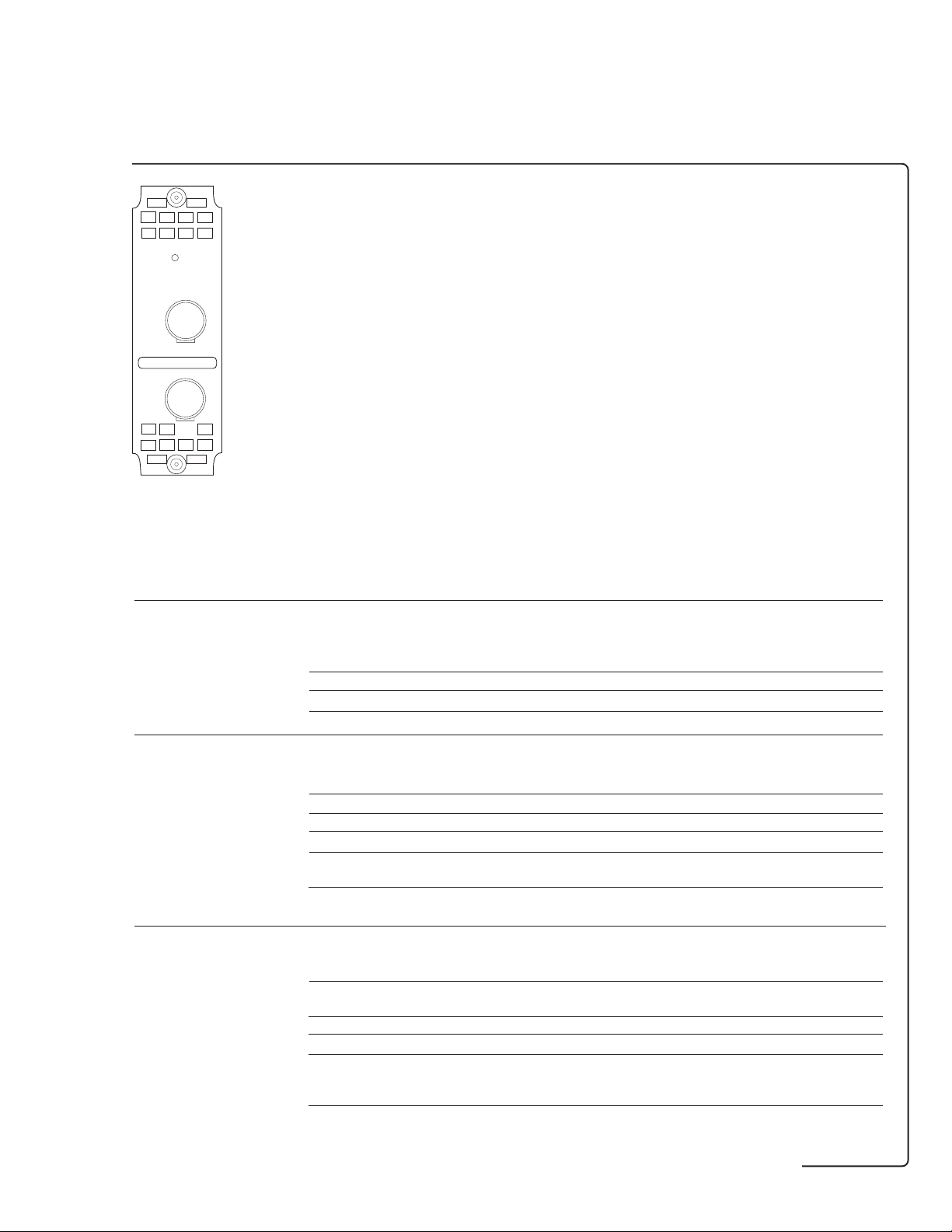
STM-1 optical interfacing
ATM
Option UH1
STM-1 (1310 nm) optical
interfacing. Also provides
STM-1
LASER
ON
OUT
CLASS 1 LASER PRODUCT
IN
Option UH1
OC-3 optical interfacing when
used in conjunction with dual
standard SONET/SDH
option 120.
STM-1 optical interfacing options STM-1
Requires option A1T, A3R or 120 to be fitted.
OUT and IN ports (used for transmit and receive)
Type Optical. ●
Connectors Customer exchangeable optical adaptors allow a range of interfaces to be attached.
Rate STM-1 (155.52 Mb/s). ●
Line code NRZ. ●
Transmitter
Wavelength 1280 to 1330 nm. ●
Spectral width (3 dB) 2.5 nm rms. ●
Optical power output Nominal. −9 dBm
Source type SLM (single mode). ●
Tx classification to STM-1 (parameters Table 2 G.957):
ITU-T G.957 S-1.1 (1310 nm). ●
Safety classification Class 1 (EN 60825-1): 1994. ●
Class I (21 CFR CH1 1040.10 (1996). ●
Receiver
Wavelength 1270 to 1600 nm. ●
Minimum sensitivity Using 1300 nm wavelength, 100% modulation depth and BER of 10
and PRBS of 2
Maximum input power For BER of 10
Detector type MLM (multi mode).* ●
Rx classification to STM-1 (parameters Table 2 G.957):
ITU-T G.957 S-1.1 (1310 nm); ●
S-1.2 (1550 nm). ●
Alarms detected Loss of optical signal. ●
23
− 1.
−10
. −8 dBm
−10
(1310 nm)
UH1
−28 dBm
* MLM receivers work with both MLM (multi mode) and SLM (single mode) transmitters.
67
Page 68

STM-4 and STM-1 test and optical interfacing
ATM
Option USN
STM-4 and STM-1 overhead
access, thru mode. Dual 1310 and
1550 nm optical interfaces and
optical power measurement.
Option UKT
STM-4 and STM-1 overhead
access, thru mode. 1310 nm
optical interfaces and optical
power measurement.
Option USN Option UKT
STM-4 and STM-1 test and interfacing options USN UKT
Requires an STM-1 test option (A1T) to be fitted. 1550 nm)
OUT and IN ports (used for transmit and receive)
Type Optical. ●●
Electrical monitor point. ●●
Connectors Customer exchangeable optical adaptors allow a range of interfaces ●●
to be attached.
Electrical monitor port: SMA (50 ohm ECL). ●●
Rate STM-1 (155.52 Mb/s). ●●
STM-4 (622.08 Mb/s). ●●
Line code NRZ. ●●
Transmitter
Wavelength 1280 to 1330 nm. ●●
1520 to 1565 nm. ● –
Spectral width (3dB) 2.5 nm rms. ●●
Extinction ratio > 8.2 dB nominal 1310 nm. ●●
> 10 dB nominal 1550 nm. ● –
Optical power output 1310 nm nominal. −10 dBm −10 dBm
1550 nm nominal. −1 dBm –
Source type SLM (single mode). ●●
Tx classification to STM-1 (parameters Table 2 G.957):
ITU-T G.957 S-1.1 (1310 nm); ●●
L-1.2 (1550 nm). ● –
STM-4 (parameters Table 3 G.957):
S-4.1 (1310 nm); ●●
L-4.2 (1550 nm). ● –
Safety classification Class I (FCC 21 CFR CH.1 1040.10 (1994)). ●●
Class 3A (EN 60825-1:1994). ●●
(1310 and (1310 nm)
68
Page 69

ATM
STM-4 and STM-1 test and interfacing options (continued) USN UKT
(1310 and (1310 nm)
1550 nm)
Receiver
Wavelength 1200 to 1600 nm. ●●
Minimum sensitivity Using 1300 nm wavelength, 100% modulation depth and BER of 10
and PRBS of 2
155 Mb/s . −34 dBm −34 dBm
622 Mb/s . −28 dBm −28 dBm
Maximum input power For BER of 10
Detector type MLM (multi mode)*. ●●
Rx classification to STM-1 (parameters Table 2 G.957):
ITU-T G.957 S-1.1, L-1.1 (1310 nm); ●●
S-1.2, L-1.2 (1550 nm). ●●
STM-4 (parameters Table 3 G.957):
S-4.1, L-4.1 (1310 nm); ●●
S-4.2, L-4.2 (1550 nm). ●●
Protected monitor 150 mV to 1000 mVp-p (nominal): ac coupled, nominal 50 ohm. ●●
point input level
Optical power measurement Accuracy: ± 1 dB . ●●
Range: −8 to −30 dBm.
23
− 1. To ITU-T G.957.
−10
. −8 dBm −8 dBm
Transmitter functions
Clock timing Internal. ●●
Frequency offset generation Up to ± 999 ppm in 0.1 ppm steps. ●●
STM-4 error addition
Recovered:
From received STM-1 or STM-4 optical signal. ●●
From received STM-1 electrical signal. ●●
Ext MTS: Data or clock format (as ITU-T G.811). ●●
-
Error type Single Rate 10
N
Comments ●●
−10
.
Frame A1A2 ● N in four frame words
B2 % ● N = 4 to 9 ●●
% MSP threshold, N in T where 0 ≤ N ≤ 1920 and 10 ms ≤ T ≤ 10000 s, in decade steps.
Note: STM-4 error addition capability is only available with STM-1 test
options A1T or A3R.
STM-1 error addition One STM-1 is selected for test. STM-1 error add capability is provided ●●
STM-4 alarm generation LOS, LOF, MS AIS, MS FERF. ●●
STM-1 alarm generation One STM-1 is selected for test. For STM-1 alarm generation capability ●●
Payload capability One STM-1 is selected for test. The payload data capability of the STM-1 ●●
Pointer adjustment One STM-1 is selected for test. The pointer adjustment generation ●●
generation capability of the STM-1 under test is defined by the STM-1 test option.
* MLM receivers work with both MLM (multi mode) and SLM (single mode) transmitters.
for the STM-1 under test. Refer to STM-1 test options A1T or A3R for details.
of the STM-1 under test, refer to STM-1 test options A1T or A3R for details.
under test is defined by the STM-1 test option. Refer to STM-1 test options
A1T or A3R for details. Background STM-1 contains 00010001 in all
payload bytes.
Refer to STM-1 test options A1T or A3R for details.
69
Page 70

ATM
STM-4 and STM-1 test and interfacing options (continued) USN UKT
(1310 and (1310 nm)
1550 nm)
Transmit overhead
Overhead Standard overhead values to ITU-T G.707. ●●
STM-4 RSOH: A1, A2, C1, E1, F1, D1 to D3. ●●
user-programmable MSOH: SS bits, K1, K2, D4 to D12, S1, Z2 (column 4);
bytes Z1, Z2 for STM-1 under test;
STM-1 The user-programmable STM-1 overhead capability is defined by the ●●
user-programmable STM-1 test option. Refer to STM-1 test options A1T or A3R for details.
bytes
Path overhead The user-programmable path overhead capability is defined by the ●●
user-programmable bytes STM-1 test option. Refer to STM-1 test options A1T or A3R for details.
Overhead sequence A single- or multi-byte overhead channel is over-written with a single or ●●
generation repeated sequence of programmed values. The sequence can contain up to
Overhead BER test Any overhead channel detailed above, for overhead sequences (except Z1 and Z2) ●●
MSP message Messages are displayed in text form as per ITU-T G.783 for linear ●●
generation architecture and to ITU-T G.841 for ring architectures (MSP-ring).
DCC drop/insert The DCC drop/insert capability is defined by the STM-1 test option. ●●
STM-4 thru mode The signal is passed through the instrument without being altered for ●●
M1 when STM-1 number 3 selected for test.
STM-4 user-programmable bytes are only available with STM-1 test
options A1T or A3R.
five different values each being transmitted for up to 64,000 frames.
RSOH: D1 to D3 (3-byte channel); E1, F1; C1 for STM-1 under test.
MSOH: D4 to D12 (9-byte channel); K1 to K2 (2-byte channel); S1, E2;
Z1, Z2 for STM-1 under test; M1 for STM-1 number 3 under test.
High order POH: J1, C2, G1, F2, H4, Z3, Z4, Z5.
can have a 29 − 1 PRBS inserted into a 64 kb/s channel. Single errors can be added
to the test pattern and a BER measurement performed.
User programmed sequences (K1K2). ●●
Refer to STM-1 test options A1T or A3R for details.
monitoring purposes where no protected monitor point is available.
Receiver functions
STM-4 error results B1, B2. ●●
STM-1 error results One STM-1 is selected for test. The errors detected in the payload of the ●●
STM-1 under test are defined by the STM-1 test option. Refer to STM-1
test options A1T or A3R for details.
Error analysis Refer to STM-1 test options A1T or A3R for details. ●●
Pointer results Refer to STM-1 test options A1T or A3R for details. ●●
Alarm indication LOS, LOF, OOF, LOP (refer to STM-1 test option A1T or A3R for details), ●●
MS AIS, MS FERF, K1/K2 change, clock loss.
One STM-1 is selected for test. The alarm detection capability in the ●●
payload of the STM-1 under test are defined by the STM-1 test option.
Refer to STM-1 test options A1T or A3R for details.
Alarm seconds As for alarm indication, plus power loss, NDF and missing NDF, ●●
and except clock loss.
70
Page 71

ATM
STM-4 and STM-1 test and interfacing options (continued) USN UKT
(1310 and (1310 nm)
1550 nm)
Received overhead snapshot SOH and POH from STM-1 number 1, or from STM-1 under test can be displayed. ●●
Overhead sequence capture A single- or multi-byte overhead channel can be selected to be monitored. ●●
Pointer location graph A graphical display that shows the variation with time of the AU-n ●●
Overhead BER measurement Any RSOH, MSOH or POH channel detailed above (for overhead sequences ●●
Refer to STM-1 test options A1T or A3R for details.
After a manual or programmed trigger, the captured byte values are
displayed together with the number of consecutive frames containing
the value.
RSOH: A1, A2 (6-byte channel) for STM-1 under test;
E1, F1;
C1 for STM-1 under test;
D1 to D3 (3-byte channel);
MSOH: H1 to H2 (2-byte channel) for STM-1 under test;
K1 to K2 (2-byte channel);
D4 to D12 (9-byte channel);
S1, E2, Z1, Z2 for STM-1 under test;
M1 for STM-1 number 3 under test;
High order POH: J1, C2, G1, F2, H4, Z3, Z4, Z5.
and TU-n pointer location. Refer to STM-1 test options A1T or A3R for details.
capture) can be selected and a BER measurement performed using a
29 − 1 PRBS inserted into a 64 kb/s channel. Single errors can be added to the test
pattern. Error count, error ratio, error free seconds and % error free seconds,
pattern loss seconds are measured.
71
Page 72

STM-4, STM-1 and STM-0 binary interfaces
Option 0YH
STM-4, STM-1 and STM-0 binary
interfaces provide all capability of
options 130/131.
NB: Must be ordered with option
130/131.
Option 0YH
STM-4, STM-1 and STM-4 binary interfaces SDH binary
Requires an STM-4, STM-1 and STM-0 test and interfacing option (130 or 131) to be fitted. 0YH
Out and in ports (used for transmit and receive)#
Type Electrical. ●
Connectors SMA, Tx clock and data, Rx clock and data. ●
Level ECL: 50 ohm to −2 V. ●
Rates STM-0, STM-1, STM-4. ●
Binary transmitter
Clock rate 51.84, 155.52, 622.08 MHz. ●
Clock polarity Positive or inverted. ●
Clock waveform Nominal squarewave. ●
Clock duty cycle 50% nominal. ●
Data rate 51.84, 155.52, 622.08 Mb/s. ●
Data polarity Positive or inverted. ●
binary interfacing and multiple outputs
Clock to data timing STM-0, STM-1 clock edge nominally 800 ps prior to center of data output. ●
STM-4 clock edge nominally centered on data output. ●
Binary receiver
Clock rate 51.84, 155.52, 622.08 MHz. ●
Clock polarity Positive or inverted. ●
Clock waveform Nominal squarewave. ●
Clock duty cycle 50% ± 10% nominal. ●
Data rate 51.84 Mb/s nominal, 155.52 Mb/s nominal, 622.08 Mb/s nominal. ●
Data polarity Positive or inverted. ●
Date setup and 600 ps min. ●
hold time
* STM-0, STM-1 and STM-4 thru mode is not available when using the binary interfaces to transmit or receive an
STM-0, STM-1 or STM-4 binary signal.
# Jitter generation is available on SDH NRZ interfaces when used in conjunction with jitter generation modules A3K/140.
Jitter measurement is not available on SDH NRZ interfaces.
72
Page 73

PDH binary interfaces
Option UH3
Single module providing binary interfaces
and external clock input for the PDH test
options UKK, UKJ, UKN and 110.
Option UH3
PDH binary interfaces PDH binary interfaces
Requires a PDH test option UKK, UKJ, UKN or 110 to be fitted. UH3
Transmitter
Binary data output
Data rates 700 kb/s to 50 Mb/s (TTL); ●
Format NRZ. ●
Connector BNC. ●
Source impedance Selectable, nominal TTL into 75 ohm to ground, or nominal ECL into 75 ohm to −2 V. ●
Polarity Selectable, normal or inverted. ●
Return loss > 15 dB, 500 kHz to 100 MHz (TTL), typical. ●
Protection ± 5 V maximum input voltage. ●
700 kb/s to 170 Mb/s (ECL).
PDH test option dependent. See "Related information" on page 75.
binary interfacing and multiple outputs
Binary clock output
Clock rates 700 kb/s to 50 Mb/s (TTL); ●
Format Nominal squarewave, 60/40 to 40/60 duty cycle. ●
Connector BNC. ●
Source impedance Selectable, nominal TTL into 75 ohm to ground or nominal ECL into 75 ohms to −2 V. ●
Polarity Selectable, normal or inverted. ●
Return loss > 10 dB, 500 kHz to 100 MHz (TTL), typical. ●
Protection ± 5 V maximum input voltage. ●
700 kb/s to 170 Mb/s (ECL).
PDH test option dependent. See "Related information" on page 75.
73
Page 74

PDH binary interfaces PDH binary interfaces
UH3
External binary
clock input
Clock rates 700 kb/s to 50 Mb/s (TTL); ●
Logic threshold 1.5 V (TTL), −1.3 V (ECL), ground (0 V), signal mean level. ●
Termination Selectable, nominal TTL into 75 ohm to ground, or nominal ECL into 75 ohm to −2 V. ●
Format Nominal squarewave, 60/40 to 40/60 duty cycle. ●
Connector BNC. ●
Polarity Selectable, normal or inverted. ●
Return loss > 15 dB, 500 kHz to 200 MHz (TTL), typical. ●
Protection ± 5 V maximum input voltage. ●
700 kb/s to 170 Mb/s (ECL).
Clocks the transmitter instead of internal clock source.
Coded interfaces can be clocked at the fixed telecom rates.
See "related information" on page 75.
Receiver
Binary data input
Data rates 700 kb/s to 50 Mb/s (TTL); ●
Logic threshold 1.5 V (TTL), −1.3 V (ECL), ground (0 V). ●
Termination Selectable, nominal TTL into 75 ohm to ground, or nominal ECL into 75 ohm to −2 V. ●
Format NRZ. ●
Connector BNC. ●
Polarity Selectable, normal or inverted. ●
Return loss > 15 dB, 500 kHz to 200 MHz (TTL), typical. ●
Protection ± 5 V maximum input voltage. ●
700 kb/s to 170 Mb/s (ECL).
PDH test option dependent. See "Related information" on page 75.
Binary clock input
Clock rates 700 kb/s to 50 Mb/s (TTL); ●
binary interfacing and multiple outputs
Logic threshold 1.5 V (TTL), −1.3 V (ECL), ground (0 V), signal mean level. ●
Termination Selectable, nominal TTL into 75 ohm to ground, or nominal ECL into 75 ohm to −2 V. ●
Format Nominal squarewave, 60/40 to 40/60 duty cycle. ●
Connector BNC. ●
Polarity Selectable, normal or inverted. ●
Return loss > 15 dB, 500 kHz to 200 MHz (TTL), typical. ●
Protection ± 5 V maximum input voltage. ●
700 kb/s to 170 Mb/s (ECL).
PDH test option dependent. See "Related information" on page 75.
74
Page 75

PDH binary interfaces PDH binary interface
UH3
Related information
Interworking between Binary outputs Internal clock* External clock† ●
option UH3 and the
PDH test options Module
combination:
UKK + UH3 704 kb/s, 2, 8, 34, 140 Mb/s 0.7 to 170 Mb/s
UKJ/UKN + UH3 2, 8, 34, 140 Mb/s 2, 8, 34, 140 Mb/s with
110 + UH3 2, 34 Mb/s, DS1, DS3 2, 34 Mb/s DS1, DS3 with
Coded outputs Internal clock* External clock†
Module
combination:
UKK + UH3 704 kb/s, 2, 8, 34, 140 Mb/s 0.7 to 50 Mb/s
UKJ/UKN + UH3 2, 8, 34, 140 Mb/s 2, 8, 34, 140 Mb/s with
110 + UH3 2, 34 Mb/s, DS1, DS3 2, 34 Mb/s DS1, DS3 with
* Uses instruments own internal clock
† Uses external clock supplied to instruments clock input port
Output amplitudes consistent with ITU-T G.703.
Selected bit rate determines coding scheme.
Additional measurement – Frequency measurement on external clock and receive clock input. ●
capability
– Jitter generation simultaneously of the binary clock and data outputs
(needs jitter generation option A3K/140: 2.048, 8.448, 34.368, 139.264 Mb/s).
– Jitter measurement on the binary receive clock input ●
(needs jitter measurement option UHN/A3L/A3V/A3N:
2.048, 8.448, 34.368, 139.264 Mb/s ± 100 ppm).
ability to vary rate ± 10%
ability to vary rate ± 10%
ability to vary rate ± 10%
ability to vary rate ± 10%
binary interfacing and multiple outputs
75
Page 76

Multiple PDH outputs
Option UHC
Three additional 2, 8, 34 and 140 Mb/s outputs.
MULTIPLE
OUTPUTS
75Ω
OUT
1
2
3
Option UHC
Multiple PDH outputs option Multiple PDH outputs
Must be ordered with a PDH test option (UKK, UKJ
or UKN).
Requires a PDH test option (UKK, UKJ or UKN) to be fitted. UHC
OUT ports (used for transmit)
Type Electrical: To ITU-T G.703. ●
Connectors Provides three additional output signals: BNC, 75 ohm, unbalanced. ●
Rate 704 kb/s (requires option UKK). ●
Bit delay Output 2, 4 bits; output 3, 8 bits; output 4, 12 bits; ●
(relative to main output) 139.264 Mb/s: No bit delay.
(Small Siemens 75 ohm unbalanced option available).
2.048, 8.448, 34.368 and 139.264 Mb/s. ●
binary interfacing and multiple outputs
76
Page 77

General specifications
Disk drive Standard
Configurations Save/recall of instrument configurations to/from floppy disk drive ●
general
Graphics Save/recall of stored measurements graphics to/from floppy disk drive. ●
Logging Direction of logging output to floppy disk drive. ●
PC results format Save SMG stored results in a CSV (comma separated variable) PC compatible ●
Disk management Instrument provides the following disk drive features: ●
Firmware upgrades Allows the upgrading of instrument firmware from the floppy disk drive. ●
Graphics/logging Standard
(in addition to the 5 internal stored settings).
Extends internal event based storage from 10,000 events to 310,000 events.
format for importing to PC spreadsheets etc.
Copying of instrument measurement graphics files to/from internal instrument
storage to/from floppy disk drive.
Copying of stored measurement graphics files from internal instrument
storage to floppy disk drive.
Deleting files or directories from floppy disk drive.
Renaming of files.
Labeling of floppy disks.
Formatting of floppy disks.
Max test result stores 5 internal SMG stores (stored graphics and data) ●
Graphic display Bar chart (results versus time periods with up to 1 second resolution) ●
or printout for current or stored measurement period.
Storage capacity 10,000 events (increases to 310,000 events with floppy disk drive). ●
Bar resolution 1 second or 1, 15, 60 minutes. ●
Unstructured PDH Bit error count, code error count, frame error count, CRC error count, ●
bar graphs REBE error count and PDH alarms.
(option UKK)
Structured PDH Bit error count, code error count, frame error count, CRC error count, ●
bar graphs REBE error count and PDH alarms.
(option UKJ)
ATM bar graphs Received cells, corrected HEC, non-corrected HEC, cell loss, errored cells, ●
(option UKN) misinserted cells, BEDC BIP-16, bit errors, mean cell transfer delay, min cell
binary interfacing and multiple outputs
SDH bar graphs Frame errors (A1A2), B1, B2, MS FEBE, B3, HP FEBE, HP IEC, ●
(options A1T/A3R) LP BIP, LP FEBE bit errors.
Jitter bar graphs Jitter hit count, plus jitter loss and jitter out-of-range alarms. ●
(options UHN/A3L/
A3V/A3N)
Wander bar graphs Frame slip count and bit slip count, plus no reference and excess ●
(options UHN/A3L/ wander alarms.
A3V/A3N)
Printing/logging Results, time, date and instrument control settings to internal/external ●
Print/logging period 10 minutes, 1 hour, 24 hours, user-defined (10 to 99 minutes, or 1 to 99 hours). ●
(increases with floppy disk drive – number of stores limited
only by free disk space).
transfer delay, peak-to-peak 2-point CDV, max 1-point CDV (to ITU-T I.356).
Non-conforming cell count and PDH physical layer alarms and ATM
cell layer alarms.
DS1/DS3: CRC6, P.bit parity, C-bit parity, DSn frame, FEBE.
printer or floppy disk drive.
77
Page 78

Printers HP OmniBER 717 External
Option UKX Printer
general
Internal 24-column thermal printer. – –
In-lid 80-column full-width graphics printer. ● –
Results logging Logging of instrument results to printer. ●●
Graphics logging Logging of instrument graphics results to printer. ●●
Screen dump Full-width printing of instrument screen to ● –
Environmental Printer operating temperature. 5 to 35° C–
printer at press of a key.
Printer storage temperature. −15 to +50°C–
Remote control/printer interface options A3B A3D
Capability RS-232-C printer/remote-control interface. ●●
HP-IB printer/remote-control interface. ●●
Parallel printer interface. ●●
LAN remote control interface. ● –
Distributed/remote testing
HP E4540A PC/laptop/MS Windows® software (Windows 3.1, Windows NT or Windows 95) which allows
distributed network control of HP 377xx PDH/SDH/ATM family of analyzers via a virtual instrument display.
analyzer (DNA) software Allows remote user to store and recall instrument configurations, create and run test sequences,
transfer test results to other Windows-based applications and provide quality-of-service
information for managers and customers.
Option 0A9: License to use up to 10 copies.
Option UAT: License to use unlimited copies.
For full details of centralized testing using the HP OMNIBER 717 analyzer and other telecom
testers from HP, please ask your local HP representative for brochure 5964-2240E
(distributed network analyzer software).
At remote site HP OMNIBER 717
Option USS
Instrument firmware Allows instrument to be controlled by HP E4540A distributed ●
network analyzer software. Also order an RS-232-C interface.
78
Page 79

General Standard
Preset facility Complete instrument configurations can be saved in non-volatile memory. ●
general
Supply 180 to 264, and 90 to 132 Vac; ●
Dimensions (mm) 190 (H) × 340 (W) × 470 (D) (× 510 (D) with lid fitted). ●
Weight 8 kg (unladen); 10 kg (typical). ●
Internal clock Accuracy: ± 0.5 ppm. ●
Environmental Operating temperature. 0 to +45 °C
CE mark ESD/Electrical fast transients/radiated susceptibility: Meets EN50082-1 (1992). ●
Product safety EN 61010-1 (1993); ●
EMC compatibility Immunity: EN 50082-1 (1992); ●
Regulatory standards 21 CFR CH.1 1040; ●
Four independent configurations plus one factory default can be saved.
Each store has a user-programmable name (disk drive increases storage –
number of stores only limited by free disk space).
47 to 63 Hz, 450 VA nominal.
Stability: ± 3 ppm.
Ageing: ± 1 ppm.
Storage temperature. − 20 to +70 °C
Radiation emissions/conducted emissions: Meets EN55011 (1991).
IEC 1010-1 (1990) +A1 (1992);
CSA C-22.2 No 1010.1-92.
Emmissions: EN 55011 (1991).
EN 60825-1 (1994);
Group 1, Class A;
EN 55011 (1991);
EN 50082-1 (1992).
Accessories
Optical connector-pair If you order an SDH optical interface module or SDH optical jitter
adaptor and optical measurement module, specify the connector adaptor(s) to suit your
coupler particular equipment.
Option UH4: FC/PC.
Option UH5: DIN47526.
Option UH6: ST.
Option UH7: Biconic.
Option UH8: NEC D4.
Option UKP: SC.
Option UKQ: HMS-10/HP.
HP15744A: Optical coupler.*
*Order the appropriate option. For full details of the HP 15744A optical coupler,
please ask your local HP representative for publication 5963-7498E.
HP 15722A: Telephone handset for options UKJ or UKN.
Carrying cases HP 15910B: Soft, vinyl carrying case.
Rack mount kit HP 15770A: Rack mount kit.
Warranty 3-year warranty as standard.
Manuals Option AVA: Calibration manual
Calibration certificate Option UK6: Commercial calibration certificate with test data.
HP 15772B: Hard, robust transit case.
Option OB3: Service manual.
Option OB2: One additional operating manual.
Option OBF: One additional manual for remote operation.
79
Page 80

Distributed network analyzer (DNA) features
Use HP E4540A DNA software to pin-point elusive
network faults and identify links with low
performance. The DNA software's long-term testing
and automatic results logging capability let you
easily monitor the PDH, SDH and ATM quality of
service you provide to key customers.
Monitor the network to identify performance and
signal degradation. Interactively control analyzers
for faster problem resolution.
Create and run your own customized test
sequences effectively.
Transfer results to other Windows®-based
applications and provide detailed quality-of-service
information for managers and customers.
MS Windows and Windows are US trademarks of Microsoft Corporation.
HP manufactures the HP OmniBER 717 analyzer under a quality
system approved to the international standard ISO 9001 plus TickIT
(BSI Registration Certificate No FM 10987).
Class 3a laser product
EN60825-1: 1994
Class 1 laser product
FDA 23 CER CH.1 1040.10 (1994)
For more information about Hewlett-Packard
test and measurement products, applications,
services, and for a current sales office listing,
visit our web site: http://www.hp.com/go/
tmdir. You can also contact one of the
following centers and ask for a test and
measurement sales representative.
United States:
Hewlett-Packard Company
Test and Measurement Call Center
P.O. Box 4026
Englewood, CO 80155-4026
Tel: 1 800 452 4844
Canada:
Hewlett-Packard (Canada) Ltd.
5150 Spectrum Way
Mississauga, Ontario
L4W 5G1
Tel: 1 877 894 4414
Europe:
Hewlett-Packard
European Marketing Centre
P. O. Box 999
1180 AZ Amstelveen
The Netherlands
Tel: (31 20) 547 9999
Japan:
Hewlett-Packard Japan Ltd.
Measurement Assistance Center
9-1, Takakura-Cho, Hachioji-Shi
Tokyo 192-8510, Japan
Tel: (81) 426 56-7832
Fax: (81) 426 56-7840
Latin America:
Hewlett-Packard Company
Latin American Region Headquarters
5200 Blue Lagoon Drive
9th Floor
Miami, Florida 33126
USA
Tel: (305) 267 4245/4220
Fax: (305) 267-4288
Australia/New Zealand:
Hewlett-Packard Australia Ltd.
31-41 Joseph Street
Blackburn, Victoria 3130
Australia
Tel: 1 800 629 485 (Australia)
Tel: 0 800 738 378 (New Zealand)
Fax: (61 3) 9210 5489
Asia Pacific:
Hewlett-Packard Asia Pacific Ltd.
17-21/F Shell Tower, Times Square
1 Matheson Street, Causeway Bay
Hong Kong, SAR
Tel: (852) 2599 7777
Fax: (852) 2506 9285
Technical data is subject to change
© Copyright Hewlett-Packard Ltd 1999.
Printed in the USA
5968-3132E 07/99
 Loading...