

Page 1

TM 11-6625-3087-12
TECHNICAL MANUAL
OPERATOR’S AND ORGANIZATIONAL
MAINTENANCE MANUAL
FOR
FREQUENCY SELECTIVE LEVEL METER
AN/USM-490
(NSN 6625-01-138-3351) (EIC: N/A)
DISTRIBUTION STATEMENT A – Approved for Public Release; Distribution is
Unlimited.
HEADQUARTERS, DEPARTMENT OF THE ARMY
1 JANUARY 1987
Page 2

Page 3
TM 11-6625-3087-12
SAFETY STEPS TO FOLLOW IF SOMEONE IS THE
VICTIM OF ELECTRICAL SHOCK
DO NOT TRY TO PULL OR GRAB THE INDIVIDUAL
IF POSSIBLE, TURN OFF THE ELECTRICAL POWER
IF YOU CANNOT TURN OFF THE ELECTRICAL POWER,
PULL, PUSH, OR LIFT THE PERSON TO SAFETY
USING A WOODEN POLE OR A ROPE OR SOME
OTHER INSULATING MATERIAL
SEND FOR HELP AS SOON AS POSSIBLE
AFTER THE INJURED PERSON IS FREE OF CONTACT
WITH THE SOURCE OF ELECTRICAL SHOCK, MOVE
THE PERSON A SHORT DISTANCE AWAY AND
IMMEDIATELY START ARTIFICIAL RESUSCITATION
A
Page 4
TM 11-6625-3087-12
WARNING
HIGH VOLTAGE
is used in the operation of this equipment
DEATH ON
may result if personnel fail to
Never work on electronic equipment unless there is another person nearby who is familiar with the operation
and hazards of the equipment and who is competent in administering first aid. When the technician is aided by
operators, he must warn them about dangerous areas.
Be careful not to contact high-voltage connections of 115-volt ac input when installing or operating this
equipment.
Whenever the nature of the operation permits, keep one hand away from the equipment to reduce the hazard
of current flowing through vital organs of the body.
Do not be misled by the term “LOW VOLTAGE” Potentials as low as 50 volts may
cause death under adverse conditions.
CONTACT
observe safety precautions
B
Page 5

TM 11-6625-3087-12
C1
CHANGE ) Headquarters
) Department of the Army
No. 1 ) Washington, D.C., 25 August 2005
TECHNICAL MANUAL
OPERATOR’S AND ORGANIZATIONAL
MAINTENANCE MANUAL
FOR
FREQUENCY SELECTIVE LEVEL METER
AN/USM-490
(NSN 6625-01-138-3351) ( EIC: N/A)
DISTRIBUTION STATEMENT A – Approved for Public Release; Distribution is
Unlimited.
TM 11-6625-3087-12, dated 1 January 1987, is changed as follows:
1. Remove old pages and insert new pages as indicated below. New or changed material is
indicated by a vertical bar in the outer margin of the page. Illustration changes are indicated
by a pointing hand. New or changed part numbers are indicated by an asterisk (*).
Completely revised sections or chapters are indicated by a vertical bar adjacent to the title
only.
Remove Pages Insert Pages
None C/(D blank)
i, ii i, ii
B-1 through B-10 B-1 through B-7/(B-8 blank)
DA Forms 2028-2 DA Forms 2028
COVER COVER
2. File this change sheet in front of the publication for reference purposes.
Page 6

TM 11-6625-3087-12
C1
By Order of the Secretary of the Army:
Official:
SANDRA R. RILEY
Administrative Assistant to the
Secretar
y of the Army
0519207
PETER J. SCHOOMAKER
General, United States Army
Chief of Staff
DISTRIBUTION:
To be distributed in accordance with initial distribution number (IDN) 511719, requirements for
TM 11-6625-3087-12.
Page 7

TM 11-6625-3087-12
INSERT LATEST CHANGED PAGES. DESTROY SUPERSEDED PAGES.
LIST OF EFFECTIVE PAGES
NOTE
ON A CHANGED PAGE, THE PORTION OF THE TEXT AFFECTED BY THE LATEST CHANGE IS INDICATED BY A
VERTICAL LINE OR OTHER CHANGE SYMBOL IN THE OUTER MARGIN OF THE PAGE.
Date of issue for original and changed pages are:
Original.. 0 .. 1 Jan 1987
Change 1 25 Aug 2005
Total number of pages in this publication is 106 consisting of the following:
Page * Change
No. No.
Cover......................................... 1
C/(D blank)................................. 1
i.................................................. 1
ii, iii............................................. 0
1-0 through 3-14 ....................... 0
A-1/(A-2 blank) .......................... 0
B-1 through B-7/(B-8 blank)....... 1
C-1 through C-2......................... 0
D-1/(D-2 blank).......................... 0
E-1/(E-2 blank) .......................... 0
INDEX........................................0
* Zero in this column indicates an original page.
Change 1 C/(D blank)
Page 8

Page 9

TM 11-6625-3087-12
TECHNICAL MANUAL } HEADQUARTERS
NO. 11-6625-3087-12 } DEPARTMENT OF THE ARMY
WASHINGTON, D.C., 1 January 1987
OPERATOR’S AND ORGANIZATIONAL MAINTENANC E MANUAL
FOR
FREQUENCY SELECTIVE LEVEL METER AN/USM-490
(NSN 6625-01-138-3351) (EIC: N/A)
REPORTING ERRORS AND RECOMMENDING IMPROVEME NTS
You can help improve this manual. If you find any mistakes or if you know of a way to improve the procedures, please let
us know. Mail your letter or DA Form 2028 (Recommended Changes to Publications and Blank Forms) directly to:
Commander, U. S. Army Aviation and Missile Command, AMSAM-MMC-MA-NP, Redstone Arsenal, AL 35898-5000.
A reply will be furnished to you. You may also provide DA Form 2028 information to AMCOM via email, fax or the
World Wide Web. Our fax number is: DSN 788-6546 or Commercial 256-842-6546. Our email address is:
[email protected]. Instructions for sending an electronic 2028 may be found at the back of this manual immediately
preceding the hardcopy 2028. For the World Wi de We b u s e: https://amcom2028.redstone.army.mil.
DISTRIBUTION STATEMENT A – Approved for Public Release; Distribution is Unlimited.
TABLE OF CONTENTS
Page
HOW TO USE THIS MANUAL……………………………………………… iii
CHAPTER 1
INTRODUCTION………………………………………………………………
1-1
Section I General information……………………………………………………………. 1-1
II Equipment Description…………………………………………………………. 1-2
III Technical Principles of Operation……………………………………………… 1-5
CHAPTER 2
OPERATING INSTRUCTIONS……………………………………………….
2-1
Section I Description and Use of Operators Controls, Indicators, and Connectors……… 2-1
II Operator Preventive Maintenance Checks and Services (PMCS)……………... 2-17
III Operation Under Usual Conditions…………………………………………….. 2-18
IV Operation Under Unusual Conditions………………………………………….. 2-41
CHAPTER 3
ORGANIZATIONAL MAINTENANCE………………………………………
3-1
Section I Repair Parts, Special Tools, TMDE, and Support Equipment…………………. 3-1
II Service Upon Receipt…………………………………………………………... 3-1
III Troubleshooting………………………………………………………………… 3-2
IV Maintenance Procedures………………………………………………………... 3-5
V Preparation for Storage of Shipment…………………………………………… 3-15
CONTENTS – Continued
Change 1 i
Page 10

TM 11-6625-3087-12
CONTENTS—Continued
APPENDIX A REFERENCE . . . . . . . . . . . . . . . . . . . . . . . . . . A-1
B MAINTENANCE ALLOCATION . . . . . . . . . . . . . . . . . . . . . . . . .. . . . . . . . . . . .
C COMPONENTS OF END ITEM AND BASIC ISSUE ITEMS LIST . . . . C-1
D ADDITIONAL AUTHORIZATION LIST . . . . . . . . . . . . . . . . . . . . . . . . . . . . . . . . . . . . . . . .
B-1
D-1
E EXPENDABLE SUPPLIES AND MATERIALS LIST . . . . . . . . . . . . . . . . . . . . . . . . . . . . . . . . . .
SUBJECT INDEX
. . . . . . . . . . . . . . . . . . . . . . . . . . . . . . . . . . . . . . . . . . . .
E-1
INDEX-1
ii
Page 11

TM 11-6625-3087-12
HOW TO USE THIS MANUAL
This manual tells you about your Frequency Selective Level Meter AN/USM490 and contains instructions about how to use it during maintenance on other
electronic equipment.
The technical manual for the electronic equipment you are maintaining will tell
you where to make certain connections and when to use various accessories
which are part of the AN/USM-490.
When you first receive your AN/USM-490, start at the front of the manual and
go all the way through to the back. Become familiar with every part of the manual
and the AN/USM-490.
This manual has an edge index which will help you find specific information in a
hurry. Simply spread the pages on the right edge of the manual until the printed
blocks can be seen. Open the manual where the block on the edge of the page
lines up with your selected topic printed on the front cover block.
iii
Page 12
TM 11-6625-3087-12
1-0
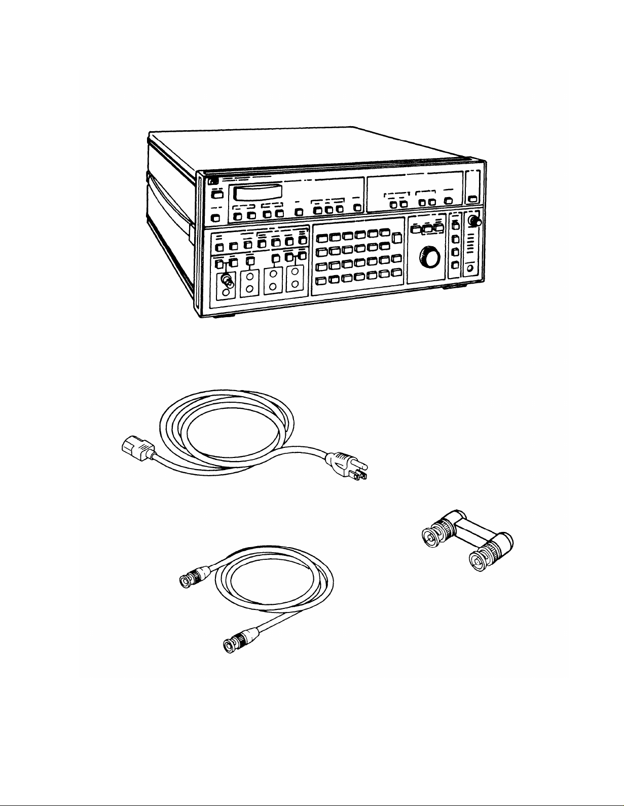
Figure 1-1. Frequency Selective Level Meter AN/USM-490.
Page 13

TM 11-6625-3087-12
CHAPTER 1
INTRODUCTION
Section I. GENERAL INFORMATION
1-1. SCOPE.
a. Type of Manual: Operator’s and Organizational Maintenance Manual.
b. Equipment Name and Model Number: Frequency Selective Level Meter AN/USM-490.
Purpose of Equipment: The Level Meter is designed for use in installation and maintenance of Frequency Domain
c.
Multiplexing (FDM) Systems, wave analysis, frequency synthesis, carrier frequency, and voice channel measurements.
1-2. CONSOLIDATED INDEX OF ARMY PUBLICATIONS AND BLANK FORMS.
Refer to the latest issue of DA Pam 310-1 to determine whether there are new editions, changes, or additional publications
pertaining to the equipment.
1-3. MAINTENANCE FORMS, RECORDS, AND REPORTS.
a Report of Maintenance and Unsatisfactory Equipment.
equipment maintenance will be those prescribed by DA PAM 738-750 as contained in Maintenance Management Update.
b. Report of Packaging and Handling Deficiencies. Fill out and forward SF 364 (Report of Discrepancy) as prescribed in
AR 735-1102/DLAR 4140.55/NAVMATINST 4355.73B/AFR 400-54/MCO 4430.3H.
c. Discrepancy in Shipment Report (DISREP) (SF 361). Fill out and forward Discrepancy in Shipment Report (SF
361) as prescribed in AR 55-38/ NAVSUPINST 4610.33C/ AFR 75-18/ MCO P4610.19D/DLAR 4500.15.
1-4. ADMINISTRATIVE STORAGE.
Refer to TM 740-90-1 for administrative storage procedures.
1-5. DESTRUCTION OF ARMY ELECTRONICS MATERIEL.
Destruction of Army electronics materiel to prevent enemy use shall be in accordance with TM 750-244-2.
1-6. REPORTING EQUIPMENT IMPROVEMENT RECOMMENDATIONS (EIR)
If your equipment needs improvement, let us know. Send us an EIR. You, the user, are the only one who can tell us
what you don’t like the design. Put it on an SF 368 (Quality Deficiency Report). Mail it to Commander, US Army
Communications-Electronics Command and Fort Monmouth, ATTN:
Jersey 07703-5000. We’ll send you a reply.
1-7. WARRANTY INFORMATION.
The AN/USM-490 is warranted by Hewlett-Packard Company for one year. Warranty starts on the date of shipment to the
original buyer. Report all defects in material or workmanship to your supervisor who will take appropriate action.
1-8. NOMENCLATURE CROSS-REFERENCE LIST.
Department of the Army forms and procedures used for
AMSEL-PA-MA-D, Fort Monmouth, New
Common names will be used when major components of the Frequency Selective Level Meter are mentioned in this manual.
NOTE
Official nomenclature must be used when filling out report forms or looking up Technical
Manuals.
Common Name
Level Meter
AIWUSM-490
Official Nomenclature
Frequency Selective Level Meter AN/USM-490
Frequency Selective Level Meter AN/USM-490
1-1
Page 14

TM 11-6625-3087-12
1-9. LIST OF ABBREVIATIONS.
This list identifies abbreviations and descriptions that are used in this manual.
AUTO
AVE
CAL
CARR
CNTR
CONT
DEMOD
DIST Distortion
FDM
LSB
MEAS
MIN
MIP
OVLD
para
pW Picawatt
STBY
SSB
T
THSHLD
USB
1-10. EQUIPMENT CHARACTERISTICS, CAPABILITIES, AND FEATURES.
Automatic
Average
Calibration
Carrier
Counter
Continue
Demodulation
Frequency Domain Multiplexing
Lower side band
Measure
Minutes
Maximum input power
Overload
Paragraph
Standby
Single side band
Time
Threshold
Upper side band
Weighted
Section Il.
EQUIPMENT DESCRIPTION
a CHARACTERISTICS.
Provides means for maintenance of Frequency Division Multiplex (FDM) systems.
Allows for:
Testing message channels (voice and carrier).
Troubleshooting voice channel malfunctions.
Message channel voice traffic simulation.
RMS wideband power measurements.
Harmonic level and distortion analysis.
Testing of high frequency radio systems.
Meets North American (Bell) Standards.
Designed for bench top use.
b. CAPABILITIES AND FEATURES.
Push button control allows for easy operation of equipment.
Annunciator lights on front panel for constant equipment status.
Nine digit LED for frequency display.
Four digit LED for amplitude display.
Self-test function for operational verification.
Programmed interface for remote operation.
1-2
Page 15

TM 11-6625-3087-12
1-11. EQUIPMENT DATA.
WEIGHTS AND DIMENSIONS
Frequency selective level meter:
Weight . . . . . . . . . . . . . . . . . . . . . . . . . . . . . . . . . . . . . . . . . . . . . . . . . . . . . . . . . . . . . . . . . . . . . . . . . . . . . . . . . . . . . . . . . . . . . . . . . . . . . . . . . . . . . . . . .50LB (23Kg)
Length
Width
Height
. . . . . . . . . . . . . . . . . . . . . . . . . . . . . . . . . . . . . . . . . . . . . . . . . . . . . . . . . . . . . . . . . . . . . . . . . . . . . . . . . . . . . . . . . . . . . . . . . . . . . . . . . . . . . . . . . .
. . . . . . . . . . . . . . . . . . . . . . . . . . . . . . . . . . . . . . . . . . . . . . . . . . . . . . . . . . . . . . . . . . . . . . . . . . . . . . . . . . . . . . . . . . . . . . . . . . . . . . . . . . . . . . . . . . .
. . . . . . . . . . . . . . . . . . . . . . . . . . . . . . . . . . . . . . . . . . . . . . . . . . . . . . . . . . . . . . . . . . . . . . . . . . . . . . . . . . . . . . . . . . . . . . . . . . . . . . . . . . . . . . . . . . . . . . . . . . .
18.38 IN. (466.7
16.75 IN. (425.5
7 IN. (177
MM)
MM)
MM)
BNC to BNC adapter:
Contact centers
. . . . . . . . . . . . . . . . . . . . . . . . . . . . . . . . . . . . . . . . . . . . . . . . . . . . . . . . . . . . . . . . . . . . . . . . . . . . . . . . . . . . . . . . . . . . . . . . . . . . . . . . .
1.750 IN. (44.5
MM)
POWER REQUIREMENTS
Voltage
. . . . . . . . . . . . . . . . . . . . . . . . . . . . . . . . . . . . . . . . . . . . . . . . . . . . . . . . . . . . . . . . . . . . . . . . . . . . . . . . . . . . . . . . . . . . . . . . . . . . . . . . ..
100 to 240Vac (+5, -10%)
Frequency . . . . . . . . . . . . . . . .. . . . . . . . . . . . . . . . . . . . . . . . . . . . . . . . . . . . . . . . . . . . . . . . . . . . . . . . ...... 48 to 66Hz
Power
Fuse . . . . . . . . . . . . . . . . . . . . . . . . . . . . . . . . . . . . . . . . . . . . . . . . . . . . . . . . . . . . . . . . . . . . . .
Fuse . . . . . . . . . . . . . . . . . . . . . . . . . . . . . . . . . . . . . . . . . . . . . . . .
. . . . . . . . . . . . . . . . . . . . . . . . . . . . . . . . . . . . . . . . . . . . . . . . . . . . . . . . . . . . . . . . . . . . . . . . . . . . . . . . . . . . . . . . . . . . . . . . . . . . . . . . . . . . . . . . . . . . . . . . . . . . . . . . . . . . ...
2.0 Amp 115Vac operation
1.0 Amp 240Vac operation
150V/A
ENVIRONMENTAL
Operating temperature range . . . . . . . . . . . . . . . . . . . . . . . . . . . . . . . . . . . . . . . . . . . . . . . . . . . . . . . . . 0 to +55° C
Storage temperature range
Storage temperature range
Relative humidity
Operating altitude
. . . . . . . . . . . . . . . . . . . . . . . . . . . . . . . . . . . . . . . . . . . . . . . . . . . . . . . . . . . . . . . . . . . . . . . . . . . . . . . . . . . . . . . . . . . . . . . . . . . . . . . . . . . . .
. . . . . . . . . . . . . . . . . . . . . . . . . . . . . . . . . . . . . . . . . . . . . . . . . . . . . . . . . . . . . . . . . . . . . . . . . . . . . . . . . . . . . . . . . . . . . . . . . . . . . . . . . . . . . .
. . . . . . . . . . . . . . . . . . . . . . . . . . . . . . . . . . . . . . . . . . . . . . . . . . . . . . . . . . . . . . . . . . . . . . . . . . . . . . . . . . . . . . . . . . . . . . . . . . . .
. . . . . . . . . . . . . . . . . . . . . . . . . . . . . . . . . . . . . . . . . . . . . . . . . . . . . . . . . . . . . . . . . . . . . . . . . . . . . . . . . . . . . . . . . . . . . . . . . . . .
-40 to +75° c
40 to +75° c
95% maximum
15,000 feet
Storage altitude . . . . . . . . . . . . . . . . . . . . . . . . . . . . . . . . . . . . . . . . . . . . . . . . . . . . . . . . . . . . . . . . . . . . . . . . . . . . . . . . 50,000 feet
PERFORMANCE
Frequency range:
75 and unbalanced
124 balanced
135 balanced
600 bridged
Frequency resolution
. . . . . . . . . . . . . . . . . . . . . . . . . . . . . . . . . . . . . . . . . . . . . . . . . . . . . . . . . . . . . . . . . . . . . . . . . . . . . . . . . . . . . . . . . . . . . . . . . . . . . . . . . . . . . . . .
. . . . . . . . . . . . . . . . . . . . . . . . . . . . . . . . . . . . . . . . . . . . . . . . . . . . . . . . . . . . . . . . . . . . . . . . . . . . . . . . . . . . . . . . . . . . . . . . . . . . . . . . . . . . . . . . .
. . . . . . . . . . . . . . . . . . . . . . . . . . . . . . . . . . . . . . . . . . . . . . . . . . . . . . . . . . . . . . . . . . . . . . . . . . . . . . . . . . . . . . . . . . . . . . . . . . . . . . . . . . . . . . .
. . . . . . . . . . . . . . . . . . . . . . . . . . . . . . . . . . . . . . . . . . . . . . . . . . . . . . . . . . . . . . . . . . . . . . . . . . . . . . . . . . . . . . . . . . . . . . . . . . . . . . . . .
. . . . . . . . . . . . . . . . . . . . . . . . . . . . . . . . . . . . . . . . . . . . . . . . . . . . . . . . . . . . . . . . . . . . . . . . . . . . . . . . . . . . . . . . . . . . . . . . . . . . . . .
50Hz to 32.5 MHz
4KHz to 10 MHz
4KHz to 1MHz
100Hz to 108 KHz
0.1HZ
Tuned frequency accuracy . . . . . . . . . . . . . . . . . . . . . . . . . . . . . . . . . . . . . . . . . . . . . . . . . . . . . . . . . . . . . . . . ±2 times 10-
Counter accuracy. . . . . . . . . . . . . . . . . . . . . . . . . . . . . . . . . . . . . . . . . . . . . . . . . . . . . . . . . . . . . . . . . . . . . . .
±1.0Hz
Input connector type:
75
. . . . . . . . . . . . . . . . . . . . . . . . . . . . . . . . . . . . . . . . . . . . . . . . . . . . . . . . . . . . . . . . . . . . . . . . . . . . . . . . . . . . . . . . . . . . . . . . . . . . . . . . . . . . . . . . . . . . . . . . . . . . . . . . . . .
124
. . . . . . . . . . . . . . . . . . . . . . . . . . . . . . . . . . . . . . . . . . . . . . . . . . . . . . . . . . . . . . . . . . . . . . . . . . . . . . . . . . . . . . . . . . . . . . . . . . . . . . . . . . . . . . . . . . . . . . . . . . . . . . . . . .
135
. . . . . . . . . . . . . . . . . . . . . . . . . . . . . . . . . . . . . . . . . . . . . . . . . . . . . . . . . . . . . . . . . . . . . . . . . . . . . . . . . . . . . . . . . . . . . . . . . . . . . . . . . . . . . . . . . . . . . . . . . . . . . . . .
600
. . . . . . . . . . . . . . . . . . . . . . . . . . . . . . . . . . . . . . . . . . . . . . . . . . . . . . . . . . . . . . . . . . . . . . . . . . . . . . . . . . . . . . . . . . . . . . . . . . . . . . . . . . . . . . . . . . . . . . . . . . . . . . . . . .
BNC female
WECO 372
WECO 241A
WECO 310
Return loss:
75 , 50Hz to 32.5 MHz
124 ,
10 KHz to 10MHz . . . . . . . . . . . . . . . . . . . . . . . . . . . . . . . . . . . . . . . . . . . . . . . . . . . . . . . . . . .
10 KHz to 1MHz
135 ,
600 ,
50Hz to 108 KHz
. . . . . . . . . . . . . . . . . . . . . . . . . . . . . . . .
. . . . . . . . . . . . . . . . . . . . . . . . . . . . . . . . . . . . . . . . . . . . . . . . . . . . . . . . . . . . . . . . . . . . . . . . . . . . . . . . . . . . . . . .
. . . . . . . . . . . . . . . . . . . . . . . . . . . . . . . . . . . . . . . . . . . . . . . . . . . . . . . . . . . . . . . . . . . . . . . . . . . . . . . . . . . . . . . . . . . . . . . . . . . . . . . . . . . . . . . . . . .
30dB
30dB
30dB
25dB
Balance:
124
10KHz to 10MHz . . . . . . . . . . . . . . . . . . . . . . . . . . . . . . . . . . . . . .. . . . . . . . . . . . . . . . . . . . . . . . . . . . . . . . . .
135 ,
10 KHz to 1MHz
600 ,
50Hz to 108 KHz
. . . . . . . . . . . . . . . . . . . . . . . . . . . . . . . . . . . . . . . . . . . . . . . . . . . . . . . . . . . . . . . . . . . . . . . . . . . . . . . . . . . . . . . . . . . . . . . . . . . . . . . . . . . . . . . . . . .
. . . . . . . . . . . . . . . . . . . . . . . . . . . . . . . . . . . . . . . . . . . . . . . . . . . . . . . . . . . . . . . . . . . . . .. . . . . . . . . . . . . . . . . . .
30dB
30dB
25dB
7
1-3
Page 16

TM 11-6625-3087-12
Bandwidth selectivity
Carrier rejection:
20Hz
. . . . . . . . . . . . . . . . . . . . . . . . . . . . . . . . . . . . . . . . . . . . . . . . . . . . . . . . . . . . . . . . . . . . . . . . . . . . . . . . . . . . . . . . . . . . . . . . . . . . . . . . . . . . . .
400Hz . . . . . . . . . . . . . . . . . . . . . . . . . . . . . . . . . . . . . . . . . . . . . . . . . . . . . . . . . . . . 60dB,±1100Hz
3100HZ
Adjacent charnel rejection, ±2850Hz, 3100Hz BW
Passband flatness:
20Hz
400Hz
3100HZ
Amplitude measurement range . . . . . . . . . . . . . . . . . . . . . . . . . . . . . . . . . . . . . . . . . . . . . . . . . . . . . +25dBm to–120dBm
Amplitude resolution
Amplitude accuracy (–100dBm to +20dBm):
75 . . . . . . . . . . . . . . . . . . . . . . . . . . . . . . . . . . . . . . . . . . . . . . . . . . . . . . . . . . . . . . . . . . . . ...... ±0.95dB
124
135 . . . . . . . . . . . . . . . . . . . . . . . . . . . . . . . . . . . . . . . . . . . . . . . . . . . . . . . . . . . . . . . . . . ....... ±1dB
600
Spurious responses:
Image rejection (100 to 132MHz) . . . . . . . . . . . . . . . . . . . . . . . . . . . . . . . . . . . . . . . . . . . . . . . . -80dBc
IF rejection (15625Hz)
Non–harmonic spurious signals (> 1600Hz offset)
Residual (>349Hz) . . . . . . . . . . . . . . . . . . . . . . . . . . . . . . . . . . . . . . . . . . . . . . . . . . . . . . . . . . . . . -115dBc
. . . . . . . . . . . . . . . . . . . . . . . . . . . . . . . . . . . . . . . . . . . . . . . . . . . . . . . . . . . . . . . . . . . . . . . . . . . . . . . . . . . . . . . . . . . . . . . . . . . . . . . . . . . . . . . . . . . . . . . . . .
. . . . . . . . . . . . . . . . . . . . . . . . . . . . . . . . . . . . . . . . . . . . . . . . . . . . . . . . . . . . . . . . . . . . . . . . . . . . . . . . . . . . . . . . . . . . . . . . . . . . . . . . . . . . . . . . . . . . . . . . . . . . .
. . . . . . . . . . . . . . . . . . . . . . . . . . . . . . . . . . . . . . . . . . . . . . . . . . . . . . . . . . . . . . . . . . . . . . . . . . . . . . . . . . . . . . . . . . . . . . . . . . . . . . . . . . . . . . . . . . . . . . . . . .
. . . . . . . . . . . . . . . . . . . . . . . . . . . . . . . . . . . . . . . . . . . . . . . . . . . . . . . . . . . . . . . . . . . . .
. . . . . . . . . . . . . . . . . . . . . . . . . . . . . . . . . . . . . . . . . . . . . . . . . . . . . . . . . . . . . . . . . . . . . . . . . . . . . . . . . . .......
. . . . . . . . . . . . . . . . . . . . . . . . . . . . . . . . . . . . . . . . . . . . . . . . . . . . . . . . . . . . . . . . . ....
. .. . . . . . . . . . . . . . . . . . . . . . . . . . . . . . . . . . . . . . . . . . . .
. . . . . . . . . . . . . . . . . . . . . . . . . . . . . . . . . . . . . . . . . . . . . . . . . . . . . . . . . . . . . . . . . . . . .
. . . . . . . . . . . . . . . . . . . . . . . . . . . . . . . . . . . . . . . . . . . . . . . . . . . . . . . . . . . . . . . . .
. . . . . . . . . . . . . . . . . . . . . . . . . . . . . . . . . . . . . . . . . . . . . . . . . . . . . . . . . . . . . . . . . . . . . . . . . . . . . . . . . . . . . . . . . . . . . . . . . . . . . . . . . . . . . . . . . .
. . . . . . . . . . . . . . . . . . . . . . . . . . . . . . . . . . . . . . . . . . . . . . . . . . . . . . . . . . . . . . . . . . . . . . . . . . . . . .
20Hz, 400Hz, and 3100HZ
30dB, ±45Hz, 60dB, ±90Hz
60dB, ±1850Hz
75dB minimum
±0.3dB at ±3Hz
±0.3dB at ±50Hz
±0.3dB at 11000Hz
±0.1dB
±1dB
±0.75dB
-80dBc
-80dBc
Distortion:
Harmonic (>4KHz) . . . . . . . . . . . . . . . . . . . . . . . . . . . . 70dB below full scale
Intermodulation (>10MHz) . . . . . . .. . . . . . . . . . . . . . . . . . . . . . . . . . . . . . . . . 70dB below full scale
Wideband power accuracy
Noise floor:
75 , 100KHz to 32.5MHz, 3100HZ . . . . . . . . . . . . . . . . . . . . . . . . . . . . . . . . . . . . . . . . . . . . . . . . . . . . . . . . -116dBm
75 , 100KHz to 32.5MHz, 20Hz and 400Hz
75 and 600 2 KHz to 100KHz . . . . . . . .. . . . . . . . . . . . . . . . . . . . . . . . . . . . . . . . . . . . . . . . . -105dBm
124 , 100KHz to 10MHz, 3100HZ . . . . . . . . . . . . . . . . . . . . . . . . . . . . . . . . . . . . . . . . . . . . . . . . . . . . 116dBm
124 , 100KHz to 10MHz,20Hzand 400Hz . . . . . . . . . . . . . . . . . . . . . . . . . . . . . . . . . . . . . -120dBm
135 , 100KHz to 1MHz, 3100HZ . . . . . . . . . . . . . . . . . . . . . . . . . . . . . . . . . . . . . . . . . . . . . . . . 116dBm
135 , 100KHz to 1MHz,20Hz and 400Hz . . . . . . . . . . . . . . . . . . . . . . . . . . . . . . . . . . . . . . . . . . -120dBm
All input impedance, 10KHz to 100 KHz
Demodulated audio output amplitude . . . . . . . . . . . . . . . . . . . . . . . . . . . . . . 0dBm into 600
Tracking output:
Amplitude
Flatness (200Hz to 32.5MHz) . . . . . . . . . . . . . . . . . . . . . . . . . . . . . . . . . . . . . . . . . ±0.5dB
Phase jitter:
Demodulated tone frequency . . . . . . . . . . . . . . . . . . . . . . . . . . . . . . . . . . . 960Hz to 1060Hz
Accuracy . . . . . . . . . . . . . . . . . . . . . . . . . . . . . . . . . . . . . . . . . . . . . . . . . . . . . . . . . . . . . . . . . . . ±(10% +0.5° p-p)
Input signal level
Residual phase jitter (50KHz to 32.5MHz)
Frequency response . . . . .. . . . . . . . . . . . . . . . . . . . . . . . . . . . . . . . . . . . . . . 20Hz to 300Hz
. . . . . . . . . . . . . . . . . . . . . . . . . . . . . . . . . . . . . . . . . . . . . . . . . . . . . . . . . . . . . . . . . . . . . . . . . . . . . . . . . . . . . . . . . . . . .
. . . . . . . . . . . . .. . . . . . . . . . . . . . . . . . . . . . . . . . . . . . . . . . . . . . . . . . . . . . . . . . . . . . .
. . . . . . . . . . . . . . . . . . . . . . . . . . . . . . . . . . . . . . . . . . . . . . . . . . . . . . . . . . . . . . . . . . . . . . . . . . . . . . . . .
. . . . . . . . . . . . . . . . . . . . . . . . . . . . . . . . . . . . . . . . . . . . . . . . . . . . . . . . . . . . . . . . . . . . . . . . . . . . . . . . . . . . . . .
0dBm into 75 at 10KHz, ±0.5dB
. . . . . . . . . . . . . . . . . . . . . . . . . . . . . . . . . . . . . . . . . . . . . . . . . . . . . . . . . . . . . . . . . . . . . . . .
. . . . . . . . . . . . . . . . . . . . . . . . . . . . . . . . . . . . . . . . . . . . . . . . . . . . . . . . . . . . . . . . . . . . . . . . . . . . . . . . . . . .
<30dB below full scale, –65dBm minimum
±2dB
-120dBm
-105dBm
<0.5° p-p
1-4
Page 17

TM 11-6625-3087-12
Weighted noise filter:
C-message
Accuracy
Impulse noise counting rate
Threshold accuracy
Notch filter rejection (995 to 1025Hz)
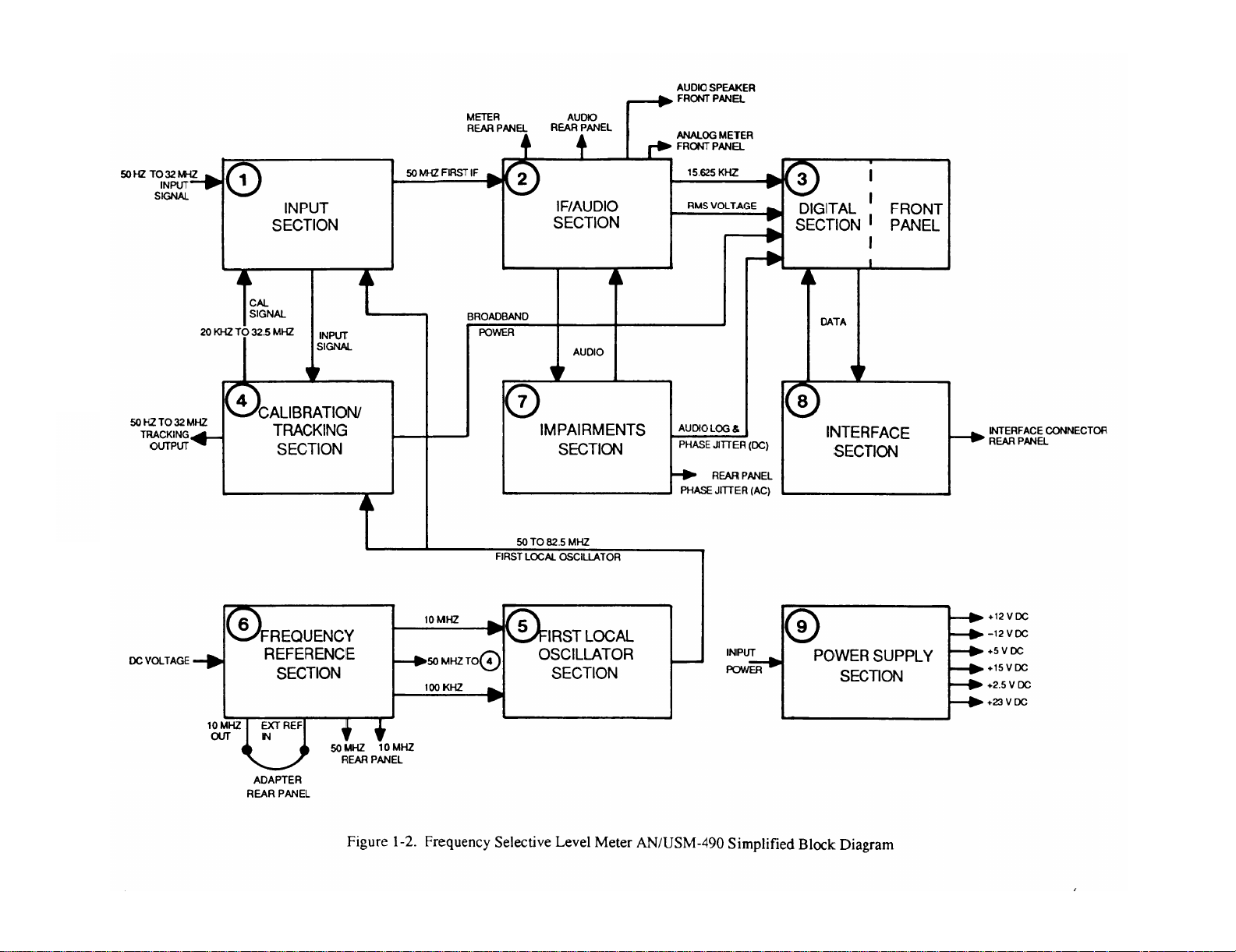
1-12. GENERAL FUNCTIONAL DESCRIPTION.
(Fig. 1-2). Frequency Selective Level Meter AN/USM-490 accepts signals from 50Hz to 32.5MHz and, dependent on the
measurement mode selected, displays the desired results on the front panel.
impedance ranges and can be balanced, unbalanced or bridged.
The desired value is displayed as amplitude in the MEASUREMENT/ENTRY display/analog meter and frequency in the
FREQUENCY/ENTRY display. Demodulated audio can be listened to using the front panel speaker or headphone jack.
. . . . . . . . . . . . . . . . . . . . . . . . . . . . . . . . . . . . . . . . . . . . . . . . . . . . . . . . . . . . . . . . . .
. . . . . . . . . . . . . . . . . . . . . . . . . . . . . . . . . . . . . . . . . . . . . . . . . . . . . . .
. . . . . . . . . . . . . . . . . . . . . . . . . . . . . . . . . . . . . . . . . . . . . . . . . . . . . . . . . . . . . . . . . . . . . . . . . . . . . . . . . . . . . . . . . . . . . .
.. . . . . . . . . . . . . . . . . . . . . . . . . . . . . . . . . . . . . . . . . . . . . . . . . . . . . . . . . . . . . . .
. . . . . . . . . . . . . . . . . . . . . . . . . . . . . . . . . . . . . . . . . . . . . . . . . . . . . . . . . . . . . . . . . . . . . . . . . . . . . . . . . . . . .
Section Ill. TECHNICAL PRINCIPLES OF OPERATION
Signals are applied using one of the five
The input signal connected to the front panel is measured, then amplified or attenuated to a usable level. This
50Hz to 32.5MHz signal is then mixed with the first local oscillator frequency of from 50MHz to 82.5MHz.
This mixing produces the first intermediate frequency of 50MHz.
143 ins/count ±5%
±1dB at 1700Hz
50dB minimum
1004Hz
±.5dB
A low pass filter keeps input frequencies greater than 32.5 MHz from being processed. This 50MHz intermediate
frequency is amplified and passed to the IF/audio section.
When CAL is on and a calibration cycle occurs, the input signal is disconnected and a precise calibration signal
from the calibration tracking section is mixed with the first local oscillator. This is then used to automatically
check and adjust the Level Meter for operation within specified limits. Once the calibration cycle is completed,
the input signal is reconnected and normal operation is resumed.
The 50MHz intermediate frequency from the input section is passed to the IF/audio section where it goes
through a 50MHz filter to bandpass to 10KHz. This 50MHz signal with 10 KHz wide bandpass is mixed with
the second local oscillator frequency of 49.984375MHz to produce a second intermediate frequency of
15.625KHz. This 15.625 KHz signal with a 10KHz wide bandpass is amplified and split into two separate
signals. One signal goes through a 400Hz filter. The result is one 15.625KHz, 400Hz wide bandpass signal
and one 15.625KHz, 10KHz wide bandpass signal,
Depending on the front panel bandwidth selection, one of the 15.625KHz signals is passed or filtered, and then
amplified. The desired selected bandwidth of 20Hz, 400Hz, or 3100Hz is then obtained.
The 15.625KHz signal with the desired 20Hz,400Hz or 3100Hz bandwidth is amplified and split three ways.
The first path is to the digital section where the frequency of the input signal is determined.
The second path is computed to an RMS voltage and passed to the digital section where the amplitude of
the input signal is determined.
The third path is to the impairments section for demodulating single sideband audio.
A voltage is developed for the front panel analog meter and to the rear panel METER output connector.
Audio from the impairments section is amplified and passed to the speaker. Detected audio also goes to the rear
panel AUDIO connector.
The digital section monitors most functions in the Level Meter. This includes processing data, front panel
display changes, monitors circuit card operation, handles all front panel operator entries, performs calibration,
and diagnostic tests.
operation.
It also contains all the front panel displays, annunciators and switches necessary for
1-5
Page 18
1-6
TM 11-6625-3087-12
Figure 1-2
Page 19

TM 11-6625-3087-12
One of the outputs from the IF/audio section is compared to the first local oscillator frequency and the input
frequency is calculated. The other is a RMS voltage that is processed and the amplitude of the input signal is
calculated. These values are then sent to the front panel and shown as frequency and amplitude in the appropriate
display.
The front panel keyboard and frequency fine tune knob entries are processed in the digital section and passed to
the appropriate assembly for processing. The status of the assemblies is returned to the digital section for
corrective action or operator notification. This notification is in the form of error codes and annunciator lights
on the front panel.
The digital section contains the stored software necessary to execute the diagnostic tests and calibration cycle. A
memory is also available for store/recall of nine different front panel configurations.
The first local oscillator frequency of from 50 to 8.25 MHz is mixed with 50MHz from the frequency reference
section to produce a 0 to 32.5 MHz signal. This signal matches the tuned frequency on the front panel display.
The 0 to 32.5MHz signal is amplified and split two ways.
The first path is to the rear panel BNC connector marked Fo.
The second path is used to generate the calibration output signal of from 20KHz to 32.5MHz. When
calibration is activated, this signal goes to the input section.
When wideband mode is selected, the average broadband power present on the input signal is measured, and goes
to the digital section for display on the front panel.
The input signal is monitored for correct amplitude and if incorrect, sends an overload or underload message to
the digital section.
The first local oscillator generates a frequency of from 50MHz to 82.5MHz. This frequency is exactly 50MHz
higher than the tuned frequency displayed on the front panel. The input to the first local oscillator is a precise
10MHz and 100KHz signal from the frequency reference section.
The first part of the frequency reference section uses DC voltage to generate a stable, accurate 10MHz signal.
This signal is either:
Coupled to internal circuits using a rear panel adapter.
Not used. If not used, a stable external source of 5MHz, 3.333333MHz, 2.5MHz, 2MHz or 1MHz must be
used.
The second part of the frequency reference section generates a 5MHz signal. This 50 MHz is divided and
amplified to generate the required operating frequencies of 50MHz, 10MHZ, 2MHz, 1MHz and 100KHz. These
signals are then used in various internal operations of the Level Meter.
The impairments uses the single sideband demodulated output from the IF/audio section. A DC phase jitter
output is generated and passed to the digital section for display on the front panel. An AC phase jitter output is
provided on the rear panel.
When C-message 3100Hz is selected, the single sideband demodulated audio is applied to a weighted filter to
measure noise.
When NOISE/TONE is selected, the single sideband demodulated audio is applied to a notch filter to remove the
1004Hz tone.
When all other modes, except impulse, are selected, the single sideband demodulated audio bypasses the filters.
When IMPULSE is selected, the single sideband demodulated audio is passed to the weighted filter, if selected
and then to the notch filter. The noise is then compared to the threshold level set by the operator. Any impulse
noise spike that exceeds the threshold level is counted and passed to the digital section for display on the front
panel.
1-7
Page 20

TM 11-6625-3087-12
The interface section accepts data or instructions from the rear panel connector and sends it to the digital section
for processing. It also accepts data from the digital section and sends it to the rear panel connector for use by
other instruments.
The power supply uses the 100 to 240VAC input power, and supplies all operating voltages to the internal
circuitry of the Level Meter. These include + 12VDC, –12VDC, +5VDC, +15VDC, +2.5VDC, and +23VDC.
1-8
Page 21
CHAPTER 2
OPERATING INSTRUCTIONS
TM 11-6625-3087-12
Section I.
2-1. INTRODUCTION.
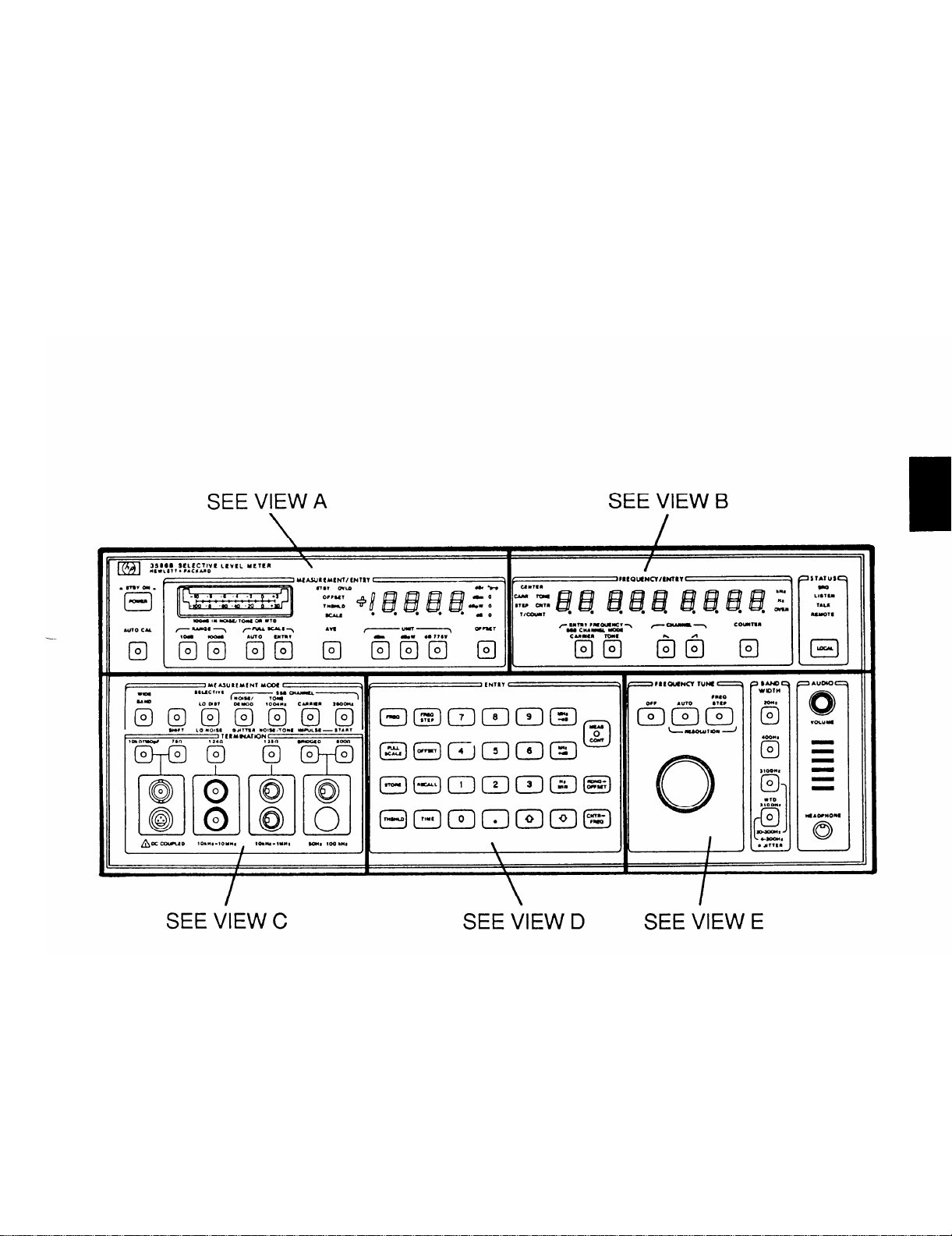
This section describes all of the operator controls and indicators for the Level Meter. Due to the large number of controls and
indicators on the front panel, it is necessary to separate the panel into five different portions. Figure 2-1 (views A thru E)
shows each portion of the front panel. The rear panel is shown in figure 2-2.
DESCRIPTION AND USE OF OPERATOR’S CONTROLS, INDICATORS,
AND CONNECTORS
Figure 2-1. Operator’s Controls, Indicators, and Connectors, front view.
2-1
Page 22
TM 11-6625-3087-12
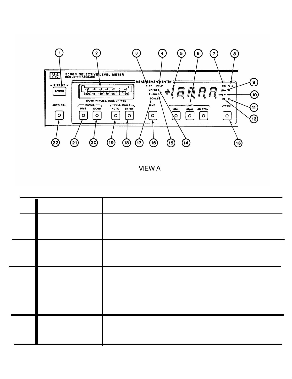
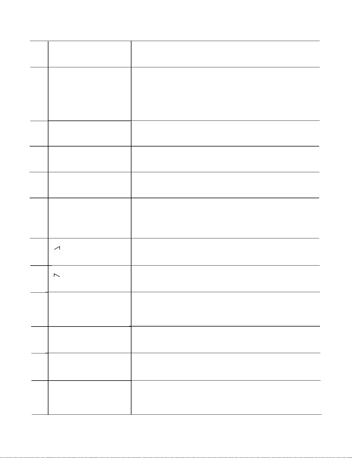
KEY
1
2
3
4
5
CONTROL, INDICATOR,
OR CONNECTOR
POWER switch
Analog meter
STBY indicator
OVLD indicator
MEASUREMENT/ENTRY
FUNCTION
Changes Level Meter from standby to on. Push in for on and push in again for
standby.
Indicates strength of signal
scale setting. Meter scale is
and bottom scale is –100dB.
Indicates Level Meter is in standby mode when on.
Flashes if input signal power level is too high. When flashing, Level Meter is
overloaded and will not measure input signal. In entry full scale, full scale level
must be increased. In auto, full scale is automatically adjusted and indicator will
flash briefly during autoranging.
Displays power level of input signal being measured. Also displays entry levels
for offset, full scale, and threshold along with error messages; calibration
messages; and underload or overload conditions.
being measured.
determined by range selection. Top scale is 10dB
Sensitivity is controlled by full
2-2
Page 23
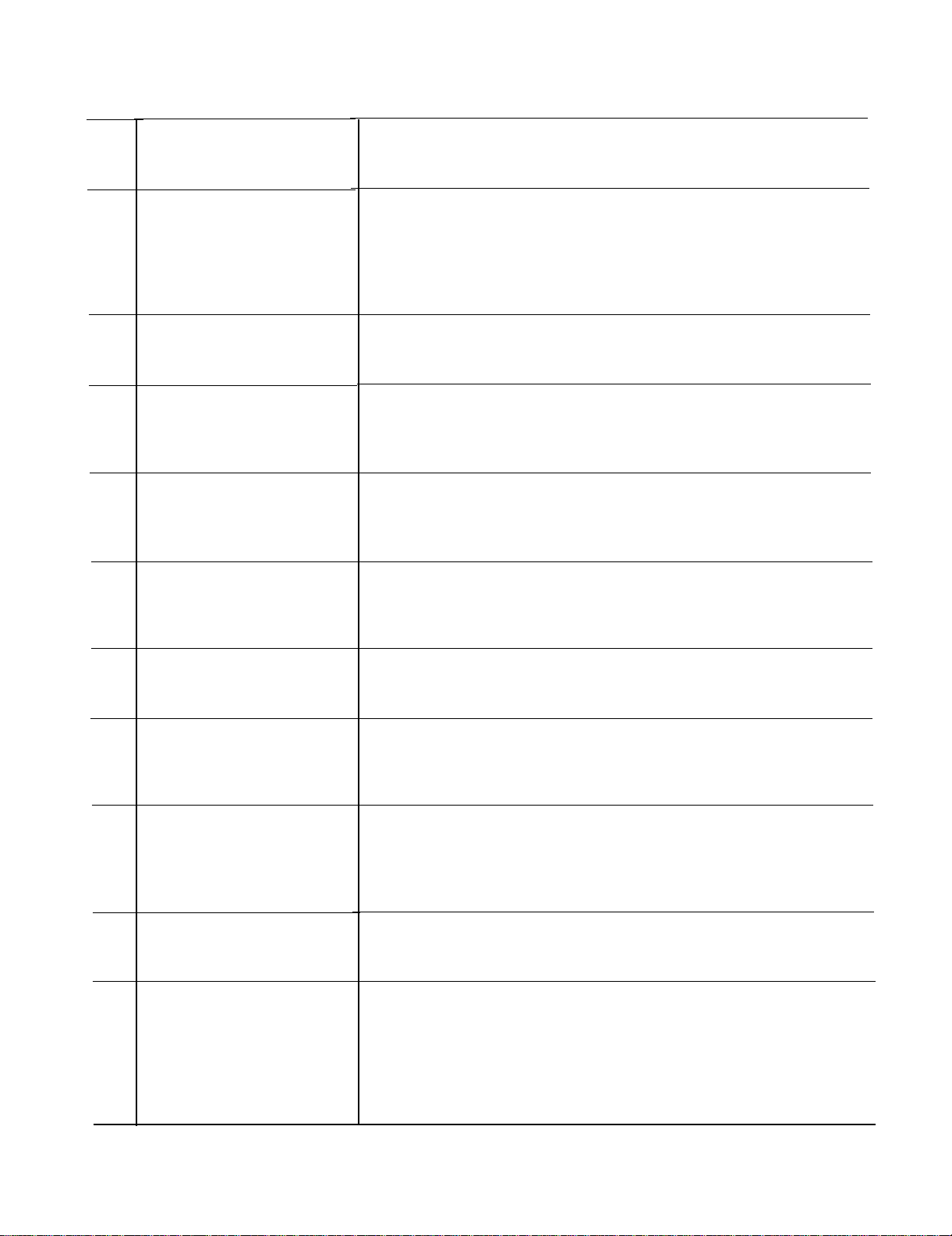
KEY
CONTROL, INDICATOR,
OR CONNECTOR
TM 11-6625-3087-12
FUNCTION
6
7
8
9
10
UNIT push buttons
dBr indicator
o
p-p indicator
dBm indicator
dBpW indicator
Selects unit of measurement for input signal. Selections are limited to dBm,
dBpw, and dB.775V. OdBm reference level is one miliwatt dissipated at the
input impedance selected. OdBpw reference level is one picowatt dissipated at
the input impedance selected. OdB.775V reference level is 0.775 volts. Lights
in push buttons indicate selection in use.
Unit of measurement for offset. When on, indicates MEASUREMENT/ENTRY
is displaying offset.
Unit of measurement for phase jitter.
When on, indicates
MEASUREMENT/ENTRY is displaying phase jitter in degrees peak to peak.
For use with phase jitter measurements only.
Unit of measurement for all modes.
When on, indicates
MEASUREMENT/ENTRY is displaying in dBm. Works with dBm push
button.
Unit of measurement for all modes.
When on,
indicates
MEASUREMENT/ENTRY is displaying in dBpW. Works with dBpW push
button.
11
12
13
14
15
O indicator
dB indicator
OFFSET push button
OFFSET indicator
THSHLD indicator
Indicates value in MEASUREMENT/ENTRY display is offset. Works with
OFFSET push button.
Unit of measurement for all modes.
When on,
indicates
MEASUREMENT/ENTRY is displaying in dB. Works with dB.775V push
button.
Subtracts stored offset from input signal power level. Zero is subtracted if no
value is stored in offset. MEASUREMENT/ENTRY displays result. When in
use, O indicator opposite unit of measure indicator lights and push button lights.
Push for on and push again for off.
Indicates Level Meter is ready to store an offset
value.
MEASUREMENT/ENTRY displays value. Lights when offset is used.
Indicates Level Meter is ready to store a threshold
value.
MEASUREMENT/ENTRY displays value. Lights when threshold is used.
2-3
Page 24

TM 11-6625-3087-12
CONTROL, INDICATOR,
KEY
OR CONNECTOR
FUNCTION
16
17
18
19
20
AVE push button
SCALE indicator
ENTRY push button
AUTO push button
100dB push button
Five level measurements of the input signal power level are taken and then
averaged. Analog meter or MEASUREMENT/ENTRY then displays new value.
Used when readings in the measurement display and analog meter are erratic.
When in use, push button lights. Push for on and push again for off.
Indicates Level Meter is ready to store a full scale value.
MEASUREMENT/ENTRY displays value. Lights when full scale is used.
Used to manually enter full scale value. Value entered must be higher than the
input signal level or an overload will exist. When in use, push button lights,
Push for on.
Tells Level Meter to automatically select full scale value for best signal to noise
ratio without overloading. When required, Level Meter will autorange to find
new full scale value. When in use, push button lights. Push for on.
Selects entire Level Meter operating range (80dB) for use in input signal
detection. Any signal level between full scale and 80dB below full scale can be
measured.
MEASUREMENT/ENTRY resolution is 0.1dB. When in use, push button
lights. Push for on.
Use 100dB scale on analog meter when selected.
21
22
10dB push button
AUTO CAL push button
Selects most linear 10dB region of Level Meter operating range (80dB) for use in
detection of input signals. Any signal level between full scale and 10dB below
full scale can be measured. Use 10dB scale on analog meter when selected.
MEASUREMENT/ENTRY resolution is 0.01dB. This selection cannot be used
in wideband and impulse measurement modes. When in use, push button lights.
Push for on.
Tells Level Meter to automatically calibrate all ranges and bandwidths of the
internal circuitry. When off, the data stored during the last calibration is used to
correct the signal being measured.
measurement modes. When in use, push button lights. Push for on and push -
again for off.
Inoperable in phase jitter and impulse
2-4
Page 25
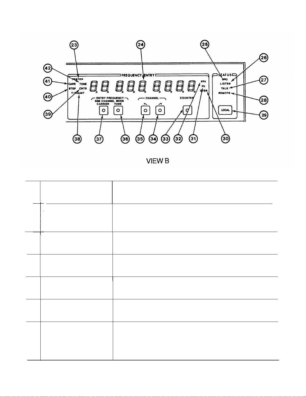
TM 11-6625-3087-12
KEY
23
24
25
26
27
28
CONTROL, INDICATOR,
OR CONNECTOR
CENTER indicator
FREQUENCY/ENTRY Displays frequency of input signal being measured. Also displays frequency,
SRQ indicator Used only when external device is connected to Level Meter. When on, one or
LISTEN indicator
TALK indicator
REMOTE indicator Used only when external device is connected to Level Meter. When on, Level
FUNCTION
—
Indicates Level Meter is in selective measurement
FREQUENCY/ENTRY display shows center frequency of Level Meter
bandwidth. Works with LO DIST or LO NOISE push buttons.
frequency steps, time and counts along with operator messages.
more external devices connected to Level Meter are requesting attention.
Used only when external device is connected to Level Meter. When on, the
Level Meter can receive data.
Used only when external device is connected to Level Meter. When on, Level
Meter can send data.
Meter can be controlled from a remote location.
mode.
2-5
Page 26
TM 11-6625-3087-12
CONTROL, INDICATOR,
KEY
OR CONNECTOR
FUNCTION
29
30
31
32
33
LOCAL push button
OVEN indicator
Hz indicator
kHz indicator
COUNTER push button
Used only when external device is connected to Level Meter. When used, Level
Meter is switched to remote operation and REMOTE indicator will come on.
All front panel controls except volume, power and local are disabled. Push for
on and push again for off. If local is pressed and Level Meter not set up for
remote operation,
“addr=XX”.
Indicates frequency reference oven is cold and its output is disabled. Comes on
when oven is cold and goes out when oven reaches operating temperature.
Unit of measurement for all modes.
displaying in hertz.
Unit of measurement for all modes.
displaying in kilohertz.
Used to display strongest single frequency signal within Level Meter bandpass.
Appropriate Hz or KHz indicator lights. Display fills with dashes if input signal
level is too low to count. When in use, push button lights. Push for on and
push again for off.
FREQUENCY/ENTRY will display digital address
When on, FREQUENCY/ENTRY is
When on, FREQUENCY/ENTRY is
34
35
36
37
38
39
push button
push button
TONE push button
CARRIER push button
T/COUNT indicator
CNTR indicator
Used only when measuring telecommunication signals. Allows Level Meter to
receive upper sideband signals. When in use, push button lights. Push for on.
Used only when measuring telecommunication signals. Allows Level Meter to
receive lower sideband signals. When in use, push button lights. Push for on.
Used to fine tune Level Meter to telecommunication signals. RF frequency of a
1004Hz test tone is entered and shown. When in use, push button lights. Push
for on.
Used to fine tune Level Meter to telecommunication signals. RF frequency of
carrier is entered and shown. When in use, push button lights, Push for on.
Indicates Level Meter will accept a time in minutes and seconds for impulse
duration. Works with TIME push button.
Indicates FREQUENCY/ENTRY is displaying measured input signal frequency.
2-6
Page 27

KEY
CONTROL, INDICATOR,
OR CONNECTOR
TM 11-6625-3087-12
FUNCTION
40
41
42
STEP indicator
CARR indicator
TONE indicator
I Indicates Level Meter is readyto store frequency step interval value. Works with
FREQ STEP push button.
Indicates Level Meter single sideband channel mode entry frequency is set to
carrier. Works with CARRIER push button.
Indicates Level Meter single sideband channel mode entry frequency is set to
tone. Works with TONE push button.
2-7
Page 28
TM 11-6625-3087-12
CONTROL, INDICATOR,
KEY OR CONNECTOR
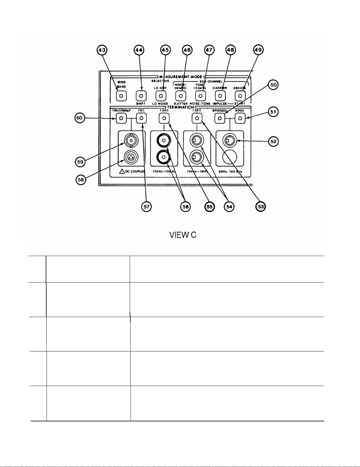
43
44
45A
45B
WIDEBAND push button
SHIFT push button
LO DIST push button
LO NOISE push button
FUNCTION
Used to measure total input signal power level. When selected, all frequency
related controls are inoperative.
See paragraph 2-12 for additional information.
Selects MEASUREMENT MODE group push button functions. When in use,
push button lights and LO NOISE,
START push buttons can be used. Push for on and push again for off.
Used for selective level measurement of non-telecommunication signals. When
in use, push button lights.
information.
Used for selective level measurement of signals spread across bandwidth. When
in use, SHIFT push button is on and LO NOISE push button lights. Push for
cm. See paragraph 2-11 for additional information.
When in use, push button lights. Push for on.
Ø
JITTER, NOISE/TONE, IMPULSE, and
Push for on. See paragraph 2-10 for additional
2-8
Page 29
KEY
CONTROL, INDICATOR,
OR CONNECTOR
TM 11-6625-3087-12
FUNCTION
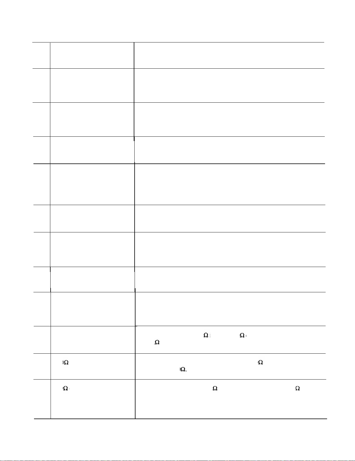
46A
46B
47A
47B
48A
48B
NOISE/DEMOD push button Used for monitoring telecommunication signals or measuring noise levels on
telecommunication signal message channels. When in use, push button lights.
Push for on. See paragraph 2-13 for additional information.
Ø JITTER push button
TONE 1004Hz push button
NOISE/TONE push button
CARRIER push button Used to measure telecommunication carrier leak signals. When in use, push
IMPULSE push button
Used to measure phase jitter of 1004HZ test tone on telecommunication signal
Ø
message channels. When in use, SHIFT push button is on and
button lights. Push for on. See paragraph 2-14 for additional information.
Used to measure test tone level of telecommunication signals. When in use,
push button lights. Push for on. See paragraph 2-15 for additional information.
Used to measure noise levels in presence of 1004Hz test tone on
telecommunication signal message channels. When in use, SHIFT push button
is on and NOISE/TONE push button lights. Push for on. See paragraph 2-16
for additional information.
button lights. Push for on. See paragraph 2-17 for additional information.
Used to count telecommunication signal message channel noise spikes. When
in use, SHIFT push button is on and IMPULSE push button lights. Push for
on. See paragraph 2-18 for additional information.
JITTER push
49A 2600Hz push button Used to measure telecommunication signaling tones. When in use, push button
lights. Push for on. See paragraph 2-15 for additional information.
49B
50
51
52 600 connectors
START push button
BRIDGED push button
600 push button Used to select balanced floating input for 600 connector. Termination
Used with impulse to start counting noise spikes. When in use, SHIFT and
IMPULSE push buttons are on but START push button does not light when
pushed. Push for on.
Used to select balanced 600 input for 600 connector. Termination impedance
is 10K shunted by 50pF. When in use, push button lights. Push for on.
impedance is 600 . When in use, push button lights. Push for on.
Used to connect bridged or 600 source to Level Meter when 600 termination
impedance is required. Connector mates with WECO type 310 plug.
2-9
Page 30
TM 11-6625-3087-12
CONTROL, INDICATOR,
KEY OR CONNECTOR
FUNCTION
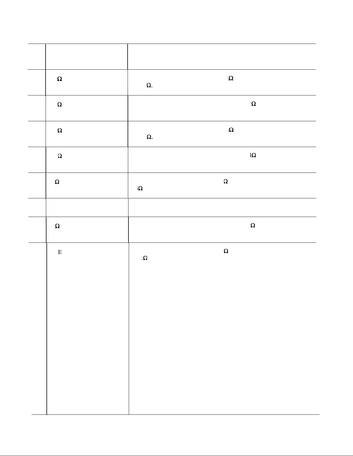
53
54
55
56
57
58
59
135 push button
I
135 connectors
124 push button
124 connectors
75 push button
Probe Power connector
75 connector Used to connect source to Level Meter when 75 termination impedance is
Used to select balanced input for both 135 connectors. Termination impedance
is 135 . When in use, push button lights. Push for on.
Used to connect source to Level Meter when 135 termination impedance is
required. Connector mates with WECO type 241 A plug.
Used to select balanced input for both 124 connectors. Termination impedance
is 124 When in use, push button lights. Push for on.
Used to connect source to Level Meter when 124 termination impedance is
required. Connector mates with WECO type 372A plug.
Used to seIect unbalanced input for 75 connector. Termination impedance is
75 . When in use, push button lights. Push for on.
Used to supply power for active probes. Mates with probe plug.
required. Mates with BNC plug. Frequency from 50Hz to 32.5MHz.
60
10k 50pF push button
Used to select unbalanced input for 75 connector. Termination impedance is
10K shunted by 50pF. When in use, push button lights. Push for on.
2-10
Page 31
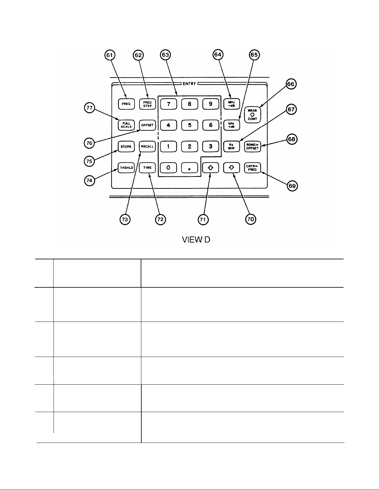
TM 11-6625-3087-12
KEY
61
62
63
64
65
CONTROL, INDICATOR,
OR CONNECTOR
FREQ push button Used to store, raise, lower, or display Level Meter tuned frequency. Push to
FREQ STEP push button
Numeric keys
MHz -dB push button Used to terminate entries from numeric keys. Frequency and frequency step are
KHz +dB push button
I
FUNCTION
display present value, and if desired, enter new value from 50Hz to 32.5MHz
using numeric keys and appropriate Hz, KHz or MHz key.
Used to store, raise, lower, or display Level Meter step value. Push to display
present value, and if desired, enter new value from 50Hz to 32.5 MHz using
numeric keys and appropriate Hz, KHz or MHz key.
Used to enter numeric value with decimal point for frequency, frequency step,
full scale, offset, threshold and time. Push desired key.
assigned MHz. Full scale, offset, and threshold are assigned -dB. Push for on.
Used to terminate entries from numeric keys. Frequency and frequency step are
assigned KHz. Full scale, offset, and threshold are assigned +dB. Push for on.
2-11
Page 32
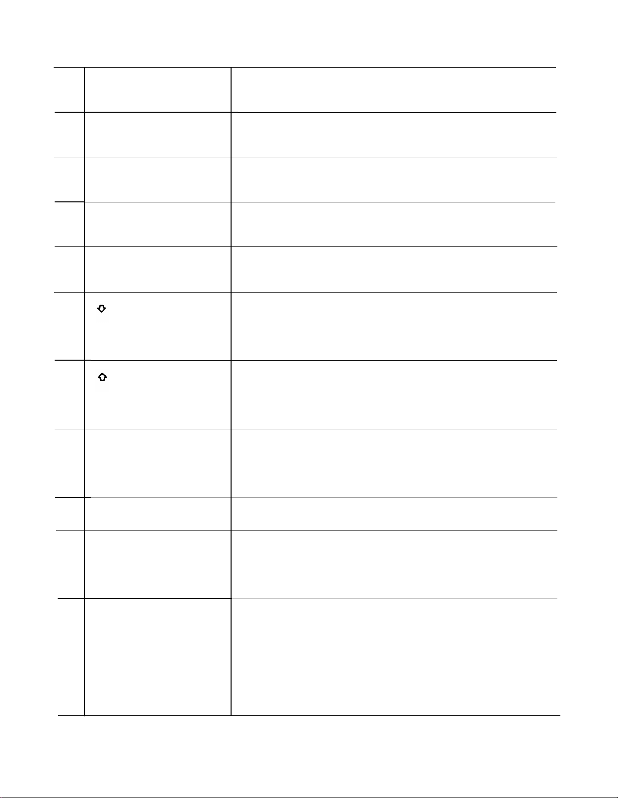
TM 11-6625-3087-12
CONTROL, INDICATOR,
KEY
OR CONNECTOR
FUNCTION
66
67
68
69
70
71
MEAS CONT push button
Hz MIN push button
RDNG-> OFFSET push
CNTR-> FREQ push button
push button
push button
Used to control measurement sequence.
displayed, push button flashes until pushed.
Used to terminate entries from numeric keys. Frequency and frequency step are
assigned Hz. Time is assigned minutes. Push for on.
Used to store value shown in MEASUREMENT/ENTRY display as new offset
in Level Meter. Push for on,
Used to fine tune Level Meter to value shown in FREQUENCY/ENTRY
display. Used only when counter is on. Push for on.
Used to lower values each time push button is pushed. Frequency step,
threshold, and time are lowered by one; full scale is lowered by five; frequency
step is lowered by power of two; and frequency is lowered by frequency step
value stored in Level Meter. Push for on.
Used to raise values each time push button is pushed. Frequency step, threshold,
and time are raised by one; full scale is raised by five; frequency step is raised by
power of two; and frequency is raised by frequency step value stored in Level
Meter. Push for on.
After value has been entered and
72
73
74
75
TIME push button
RECALL push button
THSHLD push button
STORE push button
Used to enter, raise, lower, or display duration of an impulse noise measurement.
Press to display present value, and if desired, enter a new value from O to 99
minutes 59 seconds using the numeric keys and MIN. Format is minutes,
decimal point seconds.
Used to recall Level Meter front panel measurement setup. Push for on.
Used to enter, raise, lower, or display the minimum level of noise spikes used
for impulse noise measurement.
counted, Press to display present value, and if desired, enter a new value from
–116dBm to +28dBm using the numeric keys and -dB or +dB.
Used to store Level Meter front panel measurement setup. Push for on.
Spikes present below this level will not be
2-12
Page 33

KEY
CONTROL, INDICATOR,
OR CONNECTOR
TM 11-6625-3087-12
FUNCTION
76
77
OFFSET push button
FULL SCALE push button
Used to enter, raise, lower, or display offset value stored in Level Meter. Press
to display present value, and if desired, enter anew value from -199.99dB to
+ 199.99dB using the numeric keys and -dB or +dB. New value can be stored
with offset on or off.
Used to enter, raise, lower, or display full scale value stored in Level Meter.
Press to display present value, and if desired, enter a new value using the
numeric keys and -dB or +dB. New value can be from -45dB to +25dB in 5dB
steps for 100dB range and from –120dB to +25dB in 5dB steps for 10dB range.
2-13
Page 34
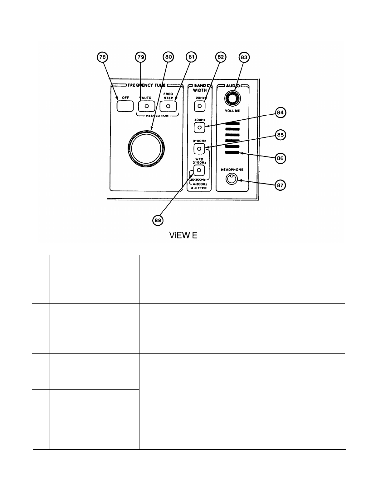
TM 11-6625-3087-12
78
79
80
81
82
CONTROL, INDICATOR,
OR CONNECTORKEY
OFF push button
AUTO push button
FREQUENCY TUNE knob
FREQ STEP push button
20Hz push button
FUNCTION
Used to disable frequency tune knob. Push for off.
Used to vary frequency tune resolution based on bandwidth selection. Frequency
steps are 100Hz for 3100Hz bandwidth, 20Hz for 400Hz bandwidth, and 1Hz for
20Hz bandwidth for 100dB range.
bandwidth, 4Hz for 400Hz bandwidth, and .2Hz for 20Hz bandwidth for 10dB
range. When in use, push button lights. Push for on.
Used to vary frequency shown in FREQUENCY/ENTRY display. Clockwise
rotation raises frequent y and counterclockwise rotation lowers frequency. Step
size determined by value stored in FREQ STEP or bandwidth selected in AUTO.
Used to vary frequency tune resolution based on frequency step value stored in
Level Meter. When in use, push button lights. Push for on.
Used to measure 20Hz section of input signal. When in use, push button lights.
Push for on.
Frequency steps are 20Hz for 3 100Hz
2-14
Page 35
KEY
CONTROL, INDICATOR,
OR CONNECTOR
TM 11-6625-3087-12
FUNCTION
83
84
85
86
87
88
VOLUME knob
400Hz push button
3100Hz push button
Loudspeaker
Headphone connector
WTD 3100Hz push button
Used to vary audio level to speaker and headphone jack. Clockwise rotation
raises volume and counterclockwise rotation lowers volume.
Used to measure 400Hz section of input signal. When in use, push button
lights. Push for on.
Used to measure 3100Hz section of input signal. When Ø Jitter on, measures
20Hz to 300Hz. When in use, push button lights. Push for on.
Used for audio monitoring of input signals or impairment measurements.
Used to audio monitoring of input signals or impairment measurements through
headphones. Output impedance is 600 and output power is 0dBm. Connector
mates with 1/4” phone plug.
Used to measure noise in 3100Hz section of input signal on telephone message
channels. When making phase jitter measurements, bandwidth is 4Hz to 300Hz.
When in use, push button lights. Push for on.
2-15
Page 36
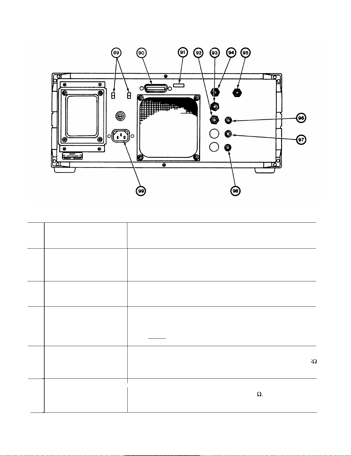
TM 11-6625-3087-12
KEY
89
90
91
92
Figure 2-2. Operator’s Controls, Indicators, and Connectors, rear view.
CONTROL, INDICATOR,
OR CONNECTOR
Line voltage switch
Interface connector
Interface control switch
Fo (0-32MHz) connector
FUNCTION
Used to select 100, 120, 220, or 240 volt operation. Two two-position
switches. Up-up for 100Vac operation, up-down for 120Vac operation, down-up
for 220Vac operation, and down-down for 240Vac operation.
Input and output connector for all external devices. Connector has 24 pins with
metric posts.
Used to select tracking generator operating mode and address of AN/USM-490.
Seven-position DIP switch.
Position one is interface troubleshooting test.
Position two sets tracking generator operating mode. Positions three thru seven
are for address settings.
Used for network analysis. Output frequency is 0 to 32.5 MHz and tracks the
front panel displayed frequency. Output power is 0dBm and impedance is 75 .
Leave open for normal use. Connector mates with BNC plug.
93
2-16
10MHZ connector
1
Used for a signal reference to synchronize external devices to Level Meter
frequency reference. Output power is +8dBm at 50 Leave open for normal
operation. Connector mates with BNC plug.
Page 37
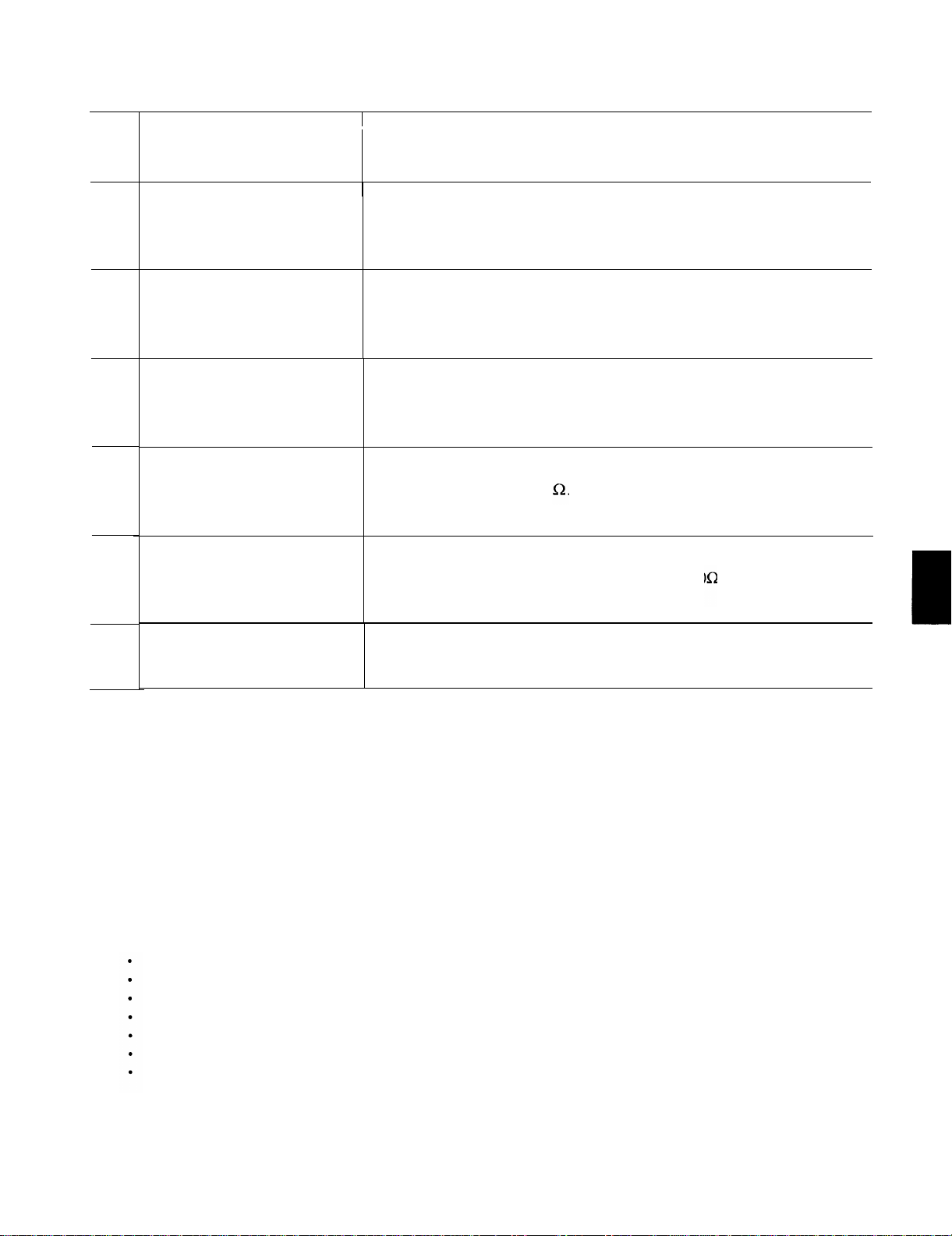
KEY
CONTROL, INDICATOR,
OR CONNECTOR
TM 11-6625-3087-12
FUNCTION
94
95
96
97
98
99
10 MHz oven connector
EXT REF 10MHz+N connector
Meter connector
Audio connector
Phase jitter connector
Power input connector
Provides a long-term, high stability frequency reference for Level Meter.
Connect to EXT REF 10MHz+N connector with BNC to BNC adapter
(supplied) for normal operation. Connector makes with BNC plug.
Used to connect 10MHz external reference to Level Meter. Input power can be
no less than - 10dBm. Connect to 10MHz oven connector with BNC to BNC
adapter (supplied) for normal operation. Connector mates with BNC plug.
Connection providing MEASUREMENT/ENTRY display reading in DC
voltage. Sensitivity is 100mv/dB on the 10dB range and 10mv/dB on the 100dB
range. Leave open for normal use. Connector mates with BNC plug.
Used for impairment measurements.
Output impedance is 1,000 . Leave open for normal operation. Connector
mates with BNC plug.
Used for additional analysis of phase jitter signal. Sensitivity is 166mv per
degree of phase jitter. Output impedance is 10,000 . Leave open for normal
operation. Connector mates with BNC plug.
I
Connector for line voltage power cable (supplied). Connector mates with CEE
22 plug.
Output level is nominally 750mV p-p.
Section Il.
2-2. GENERAL.
To be sure that your equipment is always ready for your mission, you must do scheduled preventive maintenance checks and
services (PMCS). When you are doing any PMCS or routine checks, keep in mind the WARNINGS and CAUTIONS about
electrical shock and bodily harm.
2-3. PMCS PROCEDURES.
Tools, Materials, and Equipment Required for Preventive Maintenance.
a.
operator preventive maintenance. Cleaning materials required are listed in Appendix E, items 1 and 2.
b. PMCS for Level Meter is limited to routine checks such as shown below.
cleaning,
dusting,
wiping,
checking for frayed cables,
storing items not in use,
covering unused receptacles,
checking for loose nuts, bolts, and screws.
Perform these routine checks anytime you see they must be done.
c.
OPERATOR PREVENTIVE MAINTENANCE CHECKS AND SERVICES
No tools or equipment are required for
2-17
Page 38
TM 11-6625-3087-12
Section Ill. OPERATION UNDER USUAL CONDITIONS
2-4. GENERAL.
Operation is broken down into ten individual operating procedures. Before measurement of a specific signal can be made, the
operator must determine which of the ten operation modes will perform the desired measurement. Table 2-3 is a crossreference of the Level Meter measurement mode to the type of signal to be measured. Error messages encountered during
operation will be displayed in the measurement/entry area. Table 2-2 lists all operator errors and the probable cause.
2-5. PREPARATION FOR USE.
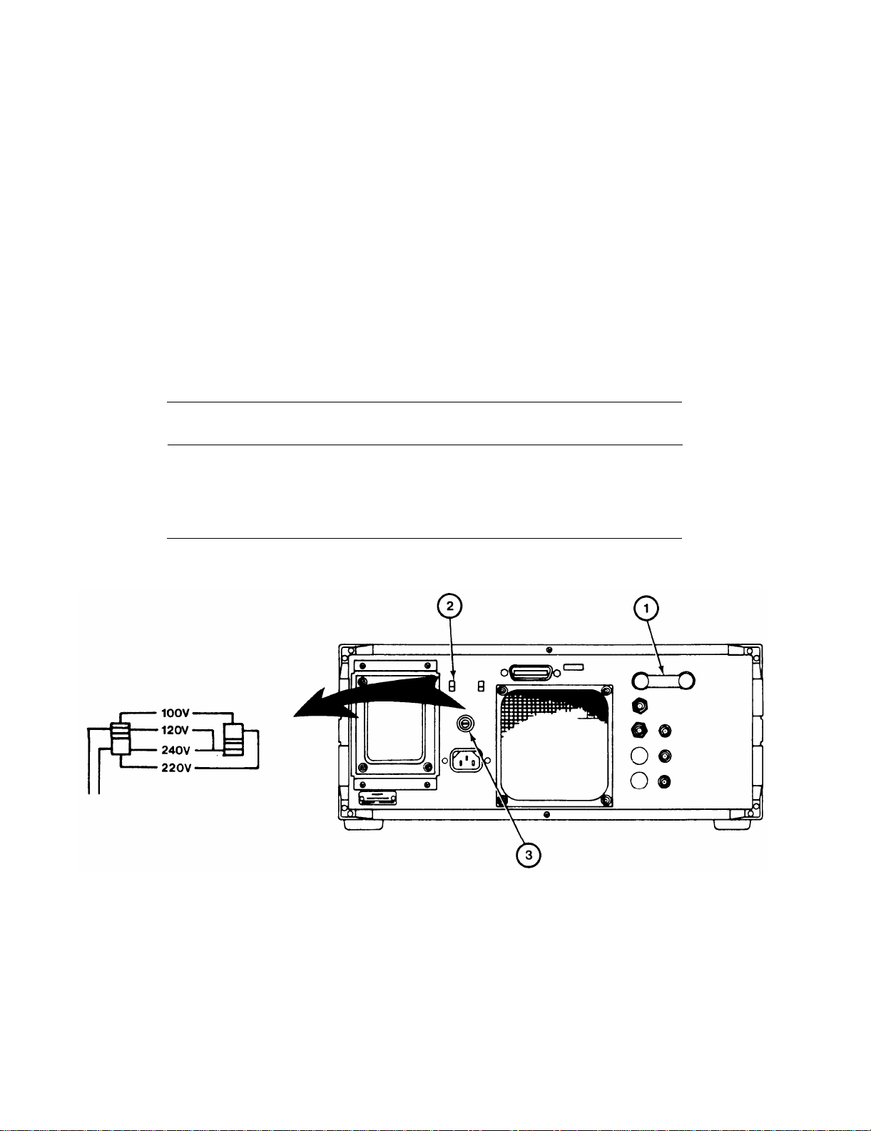
a. Connect the BNC adapter (1) to the 10MHz OVEN output and EXT REF 10MHZ input connectors on the rear panel.
b. Locate line voltage switch (2) on rear panel of Level Meter. Verify line voltage switch and fuse size are correct for
your power source (table 2-1 ).
Table 2-1. Line Voltage Switch Settings and Fuse Size.
Input Voltage
90 to 105
108 to 126
198 to 231
216t0252
c. Check fuse (3) to see if it is missing, broken, or appears to be blown. If fuse is missing, broken, or appears to be
blown, contact organizational maintenance.
Switch Position
UP UP 2 amp
UP
DOWN UP
DOWN DOWN
DOWN
Fuse
2 amp
1 amp
1 amp
2-6. TURN-ON PROCEDURES.
With the power cable connected to the rear panel power input connector, verify that the STBY light is illuminated.
a.
b. Push the POWER BUTTON (1) in and release. Verify that the button remains in and that all front panel controls and
indicators illuminate for approximately two seconds and then go blank. Verify that the fan on the rear panel is operating.
Verify that the FREQUENCY/ENTRY (2) displays “3586 b OP”. The MEASUREMENT ENTRY (3) display will
c.
cycle an AUTO CALIBRATION. It will display “CAL”.
present in the MEASUREMENT/ENTRY display, If an error is displayed, “CE”, “E” or “Err” followed by a number, see
table 2-2 for probable cause.
2-18
Verify that after the calibration cycle completes, no errors are
Page 39
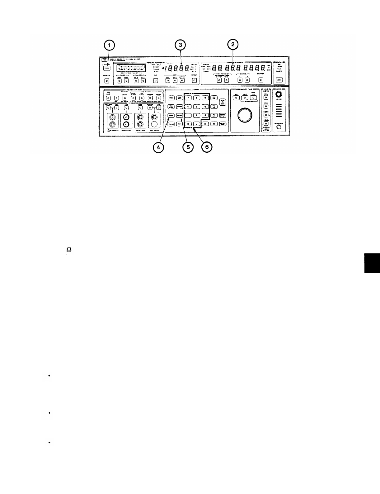
Verify the following condition exists on the Level Meter front panel:
d.
TM 11-6625-3087-12
MEASUREMENT/ENTRY display
FREQUENCY/ENTRY display
CENTER indicator
KHz indicator
AUTO CAL push button
10dB push button
AUTO push button
dBm push button
CARRIER push button
HIGHER push button
LO DIST push button
10k shunted by 50pF push button
3100Hz push button
All other controls and indicators
If the above condition is obtained and no errors are displayed, the Level Meter is ready for use in one of the ten
e.
measurement modes (table 2-3).
If the power cable has been disconnected for a period of time, the OVEN indicator will be
illuminated for approximately 20 minutes.
OVEN indicator on. The measurements obtained will not be within specification.
2-7. STORE/RECALL PROCEDURES.
ON
ON
ON
ON
ON
ON
ON
ON
ON
ON
ON
ON
ON
OFF
NOTE
Do NOT operate the Level Meter with the
Up to nine front panel control settings and entry parameters can be stored for recall at a later date as follows:
1. To store a set-up:
Press the STORE (4) push button and the desired number from 1 to 9 using the numeric key board (6). The number
selected will flash in the MEASUREMENT/ENTRY display. If a set-up was previously stored at the location
selected (1-9), it will be erased and the new set-up will be stored.
2. To recall a set-up:
Press the RECALL (5) push button and the desired number from 1 to 9 using the numeric key board (6). The set-up
previously stored at that location will display.
3. To reset the Level Meter to the turn-on condition:
Press RECALL (5), and then O (6).
2-19
Page 40

TM 11-6625-3087-12
2-8. ERROR MESSAGES.
Some operator actions and Level Meter failures cause error messages to appear in the MEASUREMENT/ENTRY display.
See table 2-2 for a list of error messages and probable cause.
NOTE
If an error appears that is not listed in table 2-2, notify next higher level of maintenance.
Table 2-2. Error Messages.
ERROR
Err 1
E 1.2
E 2.2
E 2.3
E 2.9
Err 3
E4.1
E 4.2
Err 5
PROBABLE CAUSE
The FULL SCALE level cannot be changed by the operator while
the Level Meter is in AUTOMATIC FULL SCALE.
The 10dB range cannot be used when the Level Meter is set
up in the WIDEBAND or IMPULSE measurement modes.
Ø Jitter cannot be measured because the signal level is 40dB or more
below full scale in entry.
Ø
Jitter cannot be measured because the 1 KHz test tone is not
present due to improper test setup.
0 Jitter is out of range.
Level Meter failure.
Level Meter failure.
Level Meter failure.
The Level Meter is in REMOTE operation and will not respond
to front panel controls.
CORRECTIVE ACTION
Press MEAS CONT, then ENTRY
push buttons.
Press MEAS CONT push button.
Select AUTO then 10dB RANGE.
Correct test setup.
Verify test setup. If correct, notify
next higher level of maintenance.
Notify next higher level of
maintenance.
Notify next higher level of
maintenance.
Notify next higher level of
maintenance.
Verify test setup. If correct, notify
next higher level of maintenance.
E 6.1
E 6.2
Err 7
CE-1 to 9
2-20
Accurate impulse measurements are unlikely because the THSHLD
level is 56dB or more below full scale.
The THSHLD level is more than 3dB above full scale.
Level Meter failure.
Level Meter failure.
Press MEAS CONT push button.
Increase THSHLD level or decrease
Full Scale.
Press MEAS CONT push button.
Decrease THSHLD level or increase
Full Scale.
Notify next higher level of
maintenance.
Notify next higher level of
maintenance.
Page 41

TM 11-6625-3087-12
2-9. OPERATING PROCEDURES.
The operating procedures for the Level Meter are broken down into ten individual measurement modes. See table 2-3 for the
measurement mode required to perform the desired signal measurement.
NOTE
If a signal has been measured in any one operational mode listed, the Level Meter can be
switched to another measurement mode without having to coarse or fine tune to the input
signal.
Table 2-3. Level Meter Measurement Mode Index.
TYPE OF SIGNAL MEASUREMENT
Non-telecommunication signals. Provides the best overall performance
for measuring signals other than telecommunication.
Non-telecommunication signals. Provides best performance for
measuring low level components of high level signals.
Any input signal from 50Hz to 32.5MHz. Measures only total power
of an input signal.
Telecommunication signals. Measures idle message channel noise or
translates message channel signals to voice frequencies for monitoring
or for audio output.
Telecommunication signals. Measures incidental phase modulation of
1lKHz tones on message channels.
Telecommunication signals. Measures the 1004Hz signal on a message
channel. Can be used with NOISE/TONE for signal to noise ratio on a
message channel.
Telecommunication signals. Measures noise on a message channel.
Removes 1004Hz signal component from message channel. Can be
used with TONE 1004Hz for signal to noise ratio on a message channel.
Telecommunication signals. Measures carrier leak signals or pilot tones.
LEVEL METER MEASUREMENT MODE
LO DISTORTION (para 2-10).
LO NOISE (para 2-11).
WIDEBAND (para 2-12).
NOISE/DEMODULATION (para 2-13).
PHASE JITTER (para 2-14).
TONE 1004Hz (para 2-15).
NOISE/TONE (para 2-16).
CARRIER (para 2-17).
Telecommunication signals. Measures noise spikes on message channels.
Telecommunication signals. Measures the 2600Hz signal on a message
channel. The 2600Hz tone indicates an idle message channel.
Measures the insertion loss of cables and other connection devices used
in any given testing hook-up.
IMPULSE (para 2-18).
2600Hz (para 2-15).
NETWORK ANALYSIS (para 2-19).
2-21
Page 42
TM 11-6625-3087-12
2-10. LOW DISTORTION MEASUREMENT.
NOTE
To insure optimum performance, keep cable lengths as short as possible. Try to use the
same power source for the Level Meter and the unit under test.
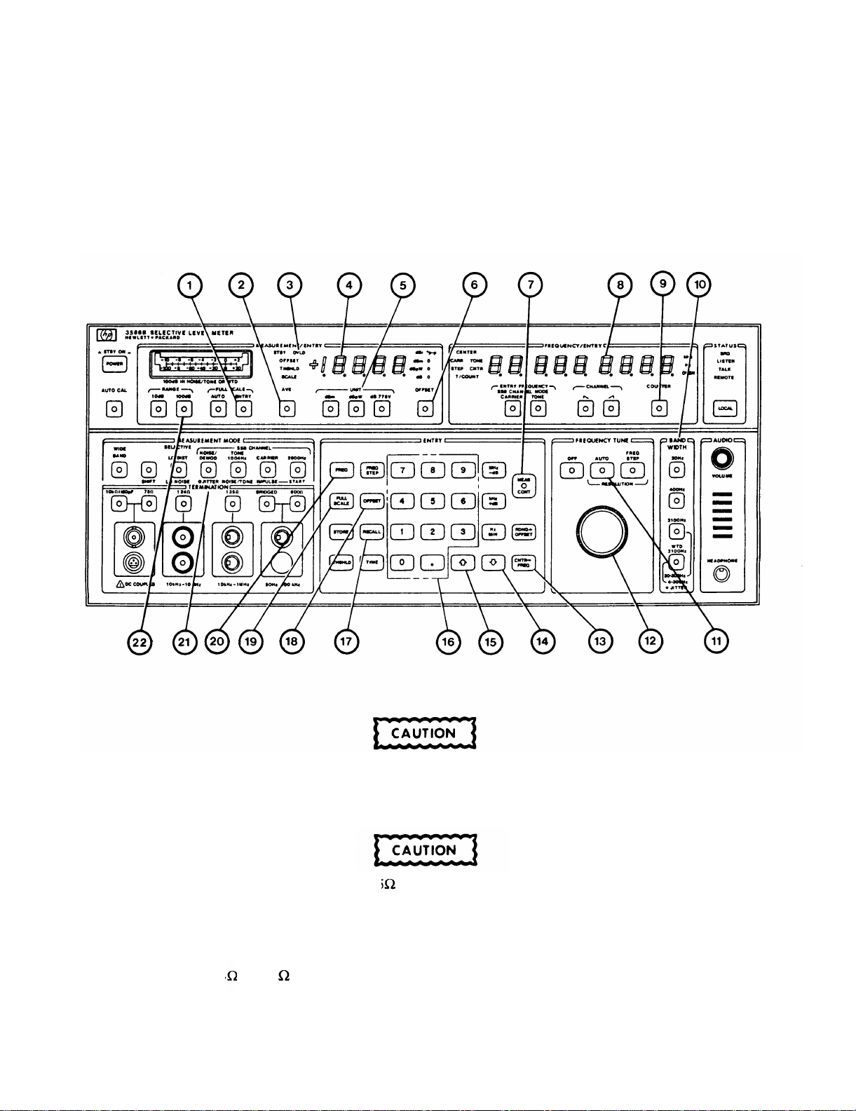
1. On Level Meter, press RECALL ( 17) then number 0 ( 16) push buttons.
The maximum input power must not exceed +27dBm or damage to internal circuitry may
result.
2. On Level Meter, select desired TERMINATION (21).
When using BNC input, use only 75 BNC plugs. Use of other impedance plugs may
damage Level Meter.
NOTE
Only 124 or 135 input may be used at one time.
3. On Level Meter, select desired UNIT of measurement (5).
2-22
Page 43

4. If an OFFSET is required,
Press OFFSET (18).
Enter offset value ( 16).
Press MEAS CONT (7).
Do not change the units after offset has been entered.
5. On Level Meter,
Press FREQ (20) and enter approximate frequency of input signal.
Press AUTO (11 ) and adjust FREQ TUNE KNOB (12) for stable indication in MEASUREMENT/ENTRY display
(3).
Press COUNTER (9).
Press CNTR->FREQ (13).
Verify FREQUENCY/ENTRY and MEASUREMENT/ENTRY indications are stable.
TM 11-6625-3087-12
NOTE
NOTE
Input signal modulation (AM or FM) may cause instability in either display.
If indications are unstable, proceed with step 8.
6. If an offset was entered in step 4, press OFFSET (6).
7. MEASUREMENT/ENTRY display (3) indicates input signal power level. FREQUENCY/ENTRY display (8) indicates
input signal frequency.
8. If MEASUREMENT/ENTRY display is unstable,
Press AVE (2). If display still unstable, turn AVE off.
Press ENTRY (1),
Press FULL SCALE (19), UP ARROW (15) or DOWN ARROW (14) then MEAS CONT (7) push buttons until
display is stable. Verify OVLD indicator (3) remains off.
Select 100dB RANGE (22).
Select 400Hz BW (10).
Select 20Hz BW (10).
2-23
Page 44
TM 11-6625-3087-12
2-11. LOW NOISE MEASUREMENT.
NOTE
To insure optimum performance, keep cable lengths as short as possible. Try to use the
same power source for the Level Meter and the unit under test.
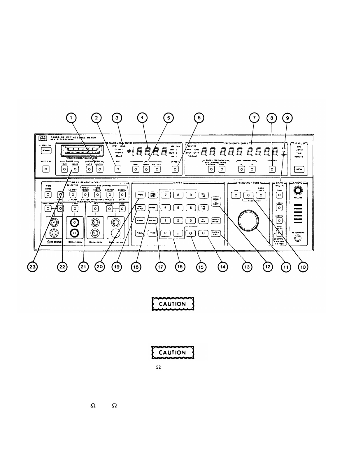
1. On Level Meter, press RECALL (17), number 0 (16), then SHIFT (22) push buttons.
The maximum input power must not exceed +27dBm or damage to internal circuitry may
result.
2. On Level Meter, select desired TERMINATION (21).
When using BNC input, use only 75 BNC plugs. Use of other impedance plugs may
damage Level Meter.
NOTE
Only 124 or 135 input may be used at one time.
3. On Level Meter, select desired UNIT of measurement (5).
2-24
Page 45

TM 11-6625-3087-12
4. If an OFFSET is required,
Press OFFSET (18).
Enter offset value (16).
Press MEAS CONT (12).
NOTE
Do not change the units after offset has been entered.
5. On Level Meter,
Press FREQ (20) and enter approximate frequency of input signal.
Press AUTO (10) and adjust FREQ TUNE KNOB (11) for stable indication in MEASUREMENT/ENTRY display
(4).
Press COUNTER (8).
Press CNTR->FREQ (13).
Verify FREQUENCYLENTRY and MEASUREMENT/ENTRY indications are stable.
NOTE
Input signal modulation (AM or FM) may cause instability in either display.
If indications are unstable, proceed with step 9.
6. If an offset was entered in step 4, press OFFSET (6).
7. MEASUREMENT/ENTRY display (4) indicates input signal power level. FREQUENCY/ENTRY display (7) indicates
input signal frequency.
8. On Level Meter, record MEASUREMENT/ENTRY indication. Press SHIFT (22) push button. Compare recorded value
to present indication. The desired mode is the one with lowest MEASUREMENT/ENTRY indication.
9. If MEASUREMENT/ENTRY display is unstable,
Press AVE (2). If display still unstable, turn AVE off.
Press ENTRY (1).
Press FULL SCALE (19), UP ARROW (15) or DOWN ARROW (14) then MEAS CONT (12) push buttons until
display is stable. Verify OVLD indicator (3) remains off.
Select 100dB RANGE (23).
Select 400Hz BW (9).
Select 20Hz BW (9).
2-25
Page 46
TM 11-6625-3087-12
2-12. WIDEBAND MEASUREMENT.
NOTE
To insure optimum performance, keep cable lengths as short as possible. Try to use the
same power source for the Level Meter and the unit under test.
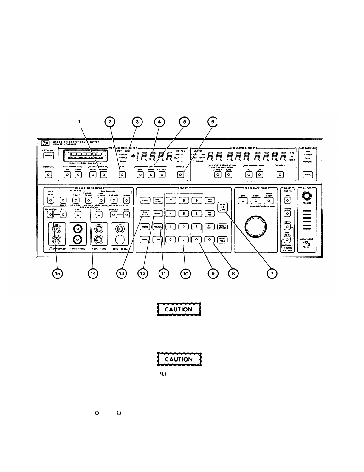
1. On Level Meter, press RECALL (11), number 0 (10), then WIDEBAND (15) push buttons.
The maximum input power must not exceed +27dBm or damage to internal circuitry may
result.
2. On Level Meter, select desired TERMNATION (14).
When using BNC input, use only 75 BNC plugs. Use of other impedance plugs may
damage Level Meter.
NOTE
Only 124 or 135 input may be used at one time.
3. On Level Meter, select desired UNIT of measurement (5).
2-26
Page 47

4. If an OFFSET is required,
Press OFFSET (12).
Enter offset value ( 10).
Press MEAS CONT (7).
Press OFFSET (6).
NOTE
Do not change the units after offset has been entered.
5. MEASUREMENT/ENTRY display (4) indicates input signal power level.
NOTE
Input signal modulation (AM or FM) may cause instability in MEASUREMENT/ENTRY display.
6. If MEASUREMENT/ENTRY display is unstable or constantly resets full scale level,
Press AVE (2). If display still unstable, turn AVE off.
TM 11-6625-3087-12
Press ENTRY (1).
Press FULL SCALE (13), UP ARROW (9) or DOWN ARROW (8) then MEAS CONT (7) push buttons until
display is stable. Verify OVLD indicator (3) remains off.
NOTE
If OVLD indicator is on or “OL” appears in MEASUREMENT/ENTRY display, increase
full scale level. If “UL” appears in MEASUREMENT/ENTRY display, decrease full
scale level.
2-27
Page 48
TM 11-6625-3087-12
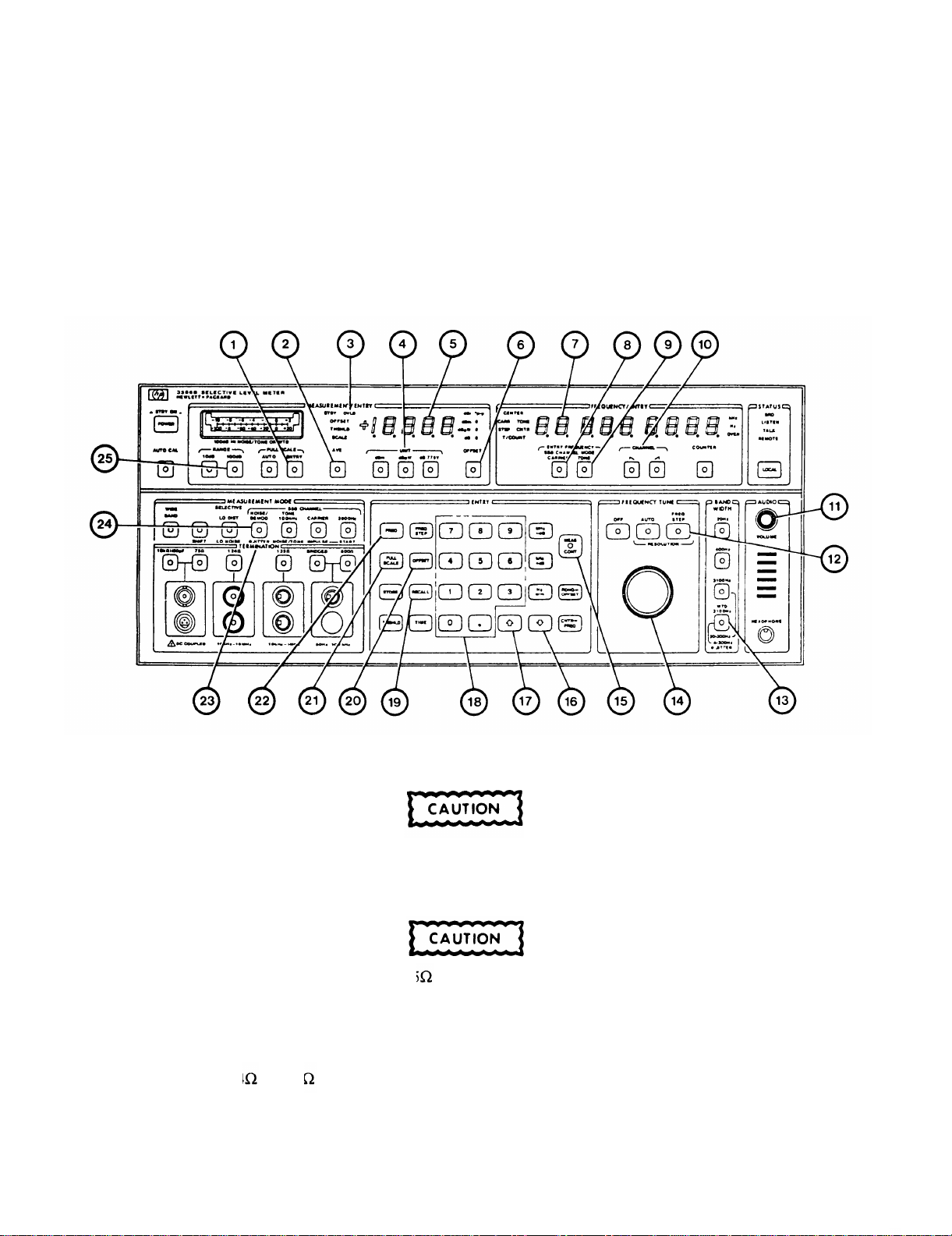
2-13. NOlSE/DEMODULAT10N MEASUREMENT.
NOTE
To insure optimum performance, keep cable lengths as short as possible. Try to use the
same power source for the Level Meter and the unit under test.
1. On Level Meter, press RECALL (19), number O (18), NOISE DEMOD (24), then WTD 3100HZ (13) push buttons.
The maximum input power must not exceed +27dBm or damage to internal circuitry may
result.
2. On Level Meter, select desired TERMINATION (23),
When using BNC input, use only 75 BNC plugs. Use of other impedance plugs may
darnage Level Meter.
NOTE
Only 124 or 135 input may be used at one time.
3. On Level Meter, select desired UNIT of measurement (4).
2-28
Page 49

TM 11-6625-3087-12
4. If an OFFSET is required,
Press OFFSET (20).
Enter offset value (18).
Press MEAS CONT (15),
NOTE
Do not change the units after offset has been entered.
5. On Level Meter, select desired sideband CHANNEL (10).
6. Tune the Level Meter to the input signal frequency as follows:
If the carrier frequency is to be used to tune the Level Meter to a message channel, press CARRIER (8), FREQ (22),
and enter the carrier frequency.
If the tone frequency is to be used to tune the Level Meter to a message channel, press TONE (9), FREQ (22), and
enter the tone frequency.
7. If an offset was entered in step 4, press OFFSET (6).
8. Verify FREQUENCY/ENTRY and MEASUREMENT/ENTRY indications are stable.
NOTE
Input signal modulation (AM or FM) may cause instability in either display.
If indications are unstable, proceed with step 11.
9. MEASUREMENT/ENTRY display (5) indicates input signal power level. FREQUENCY/ENTRY display (7) indicates
tuned carrier or tone frequency.
10. Tune the Level Meter to voice signals as follows:
Enter FREQ STEP of 1Hz.
Press MEAS CONT (15).
Increase AUDIO VOLUME (11).
Press FREQ STEP (12).
Using the FREQUENCY TUNE knob (14), slowly adjust for natural sound.
11. If MEASUREMENT/ENTRY display is unstable or constantly resets full scale level,
Press AVE (2). If display still unstable, turn AVE off.
Press ENTRY (1).
Press FULL SCALE (21), UP ARROW (17) or DOWN ARROW (16) then MEAS CONT (15) push buttons until
display is stable. Verify OVLD indicator (3) remains off.
NOTE
If OVLD indicator is on or “OL” appears in MEASUREMENT/ENTRY display, increase
full scale level. If “UL” appears in MEASUREMENT/ENTRY display, decrease full
scale level and/or select 100dB RANGE (25).
2-29
Page 50
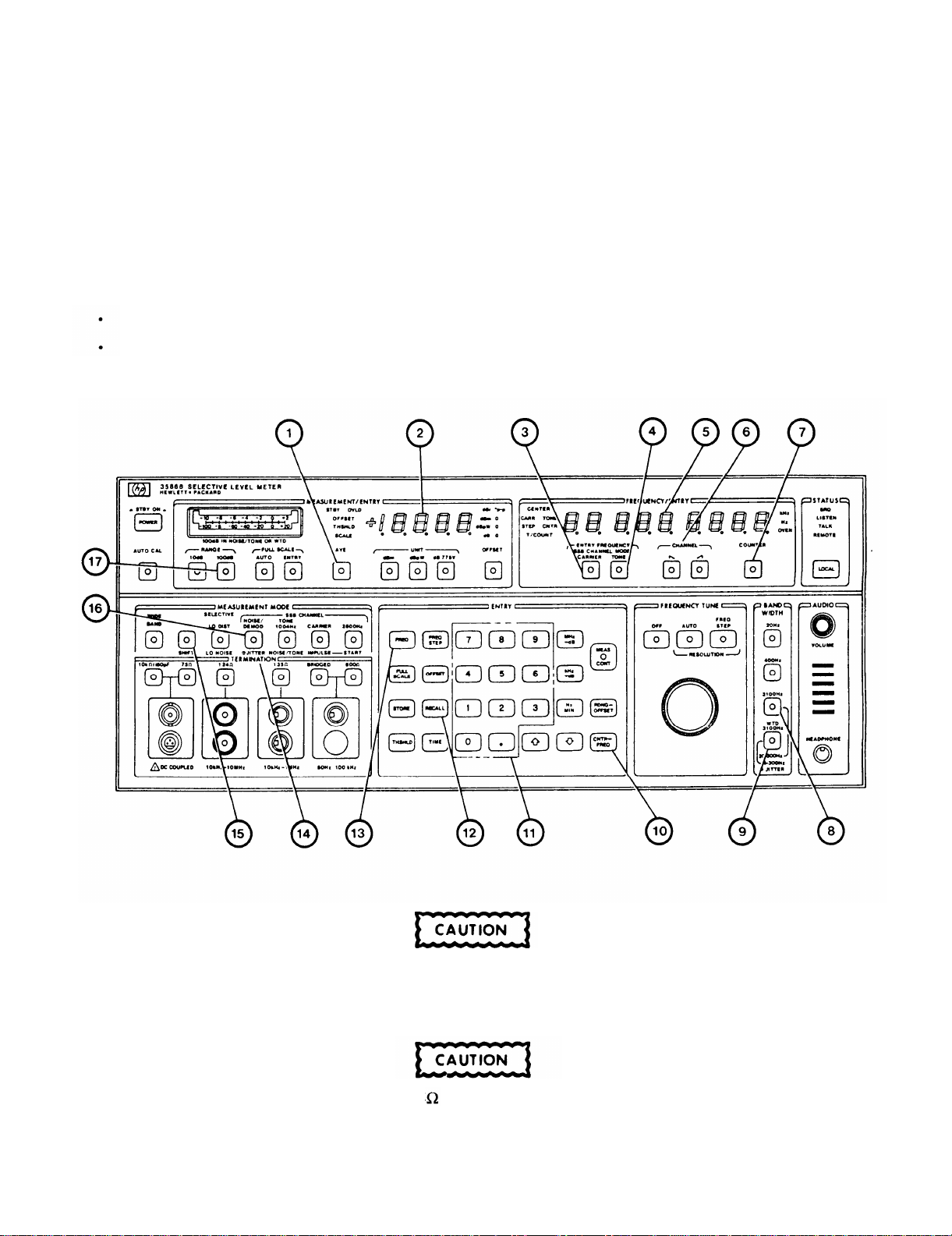
TM 11-6625-3087-12
2-14. PHASE JITTER MEASUREMENT.
NOTE
To insure optimum performance, keep cable lengths as short as possible. Try to use the
same power source for the Level Meter and the unit under test.
1. On Level Meter, press RECALL (12), number 0 (11), SHIFT (15), then Ø JITTER (16) push buttons.
2. On Level Meter,
If 20-300Hz band is desired, press 3100Hz (8) push button.
If 4-300Hz band is desired pressWTD3100Hz (9) push button.
The maximum input power must not exceed +27dBm or damage to internal circuitry may
result.
3. On Level Meter, select desired TERMINATION (14).
When using BNC input, use only 75 BNC plugs. Use of other impedance plugs may
damage Level Meter.
2-30
Page 51

TM 11-6625-3087-12
NOTE
Only 124 or 135 input may be used at one time.
4. On Level Meter, select desired sideband CHANNEL (6).
5. Tune the Level Meter to the input signal frequency as follows:
l If the carrier frequency is to be used to tune the Level Meter to a message channel, press CARRIER (3), FREQ (13),
and enter the carrier frequency.
If the tone frequency is to be used to tune the Level Meter to a message channel, press TONE (4), FREQ (13), and
enter the tone frequency.
6. Fine tune the Level Meter to the input signal frequency as follows:
Press COUNTER (7).
Press CNTR->FREQ (10).
7. MEASUREMENT/ENTRY display (2) indicates input signal phase jitter. FREQUENCY/ENTRY display (5) indicates
input signal frequency.
NOTE
Input signal modulation (AM or FM) may cause instability in either display.
8. If MEASUREMENT/ENTRY display is unstable or constantly resets full scale level,
Press AVE (1). If display still unstable, turn AVE off.
NOTE
Use AVE only when necessary because it will decrease the accuracy of this measurement.
Select 100dB RANGE (17).
2-31
Page 52
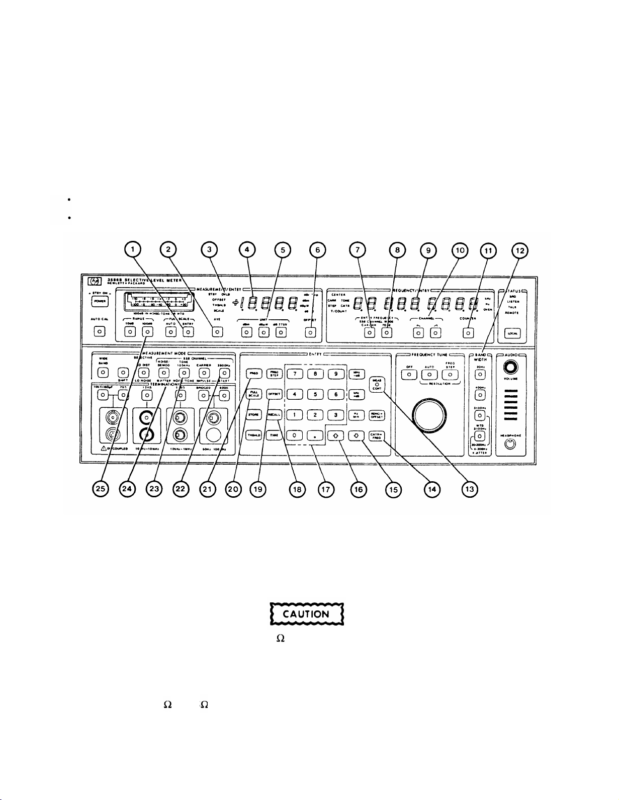
TM 11-6625-3087-12
2-15. TONE 1004Hz AND 2600Hz MEASUREMENT.
NOTE
To insure optimum performance, keep cable lengths as short as possible. Try to use the
same power source for the Level Meter and the unit under test.
1. On Level Meter, press RECALL (18) then number 0 (17) push buttons.
2. On Level Meter,
If 1004Hz measurement is desired press 1004Hz (23).
If 2600Hz measurement is desired press 2600Hz (22).
The maximum input power must not exceed +27dBm or damage to internal circuitry may
result.
3. On Level Meter, select desired TERMINATION (24).
When using BNC input, use only 75 BNC plugs. Use of other
damage Level Meter.
NOTE
Only 124 or 135 input may be used at one time.
4. On Level Meter, select desired UNIT of measurement (5).
2-32
impedance
plugs may
Page 53

5. If an OFFSET is required,
Press OFFSET (19).
Enter offset value (17).
Press MEAS CONT (13).
NOTE
Do not change the units after offset has been entered.
6. On Level Meter, select desired sideband CHANNEL (10).
7. Tune the Level Meter to the input signal frequency as follows:
If the carrier frequency is to be used to tune the Level Meter to a message channel, press CARRIER (7), FREQ (21 ),
and enter the carrier frequency.
If the tone frequency is to be used to tune the Level Meter to a message channel, press TONE (8), FREQ (21), and
enter the tone frequency.
8. Fine tune the Level Meter to the input signal frequency as follows:
Press 3100HZ (12).
TM 11-6625-3087-12
Press COUNTER (11).
Press CNTR->FREQ (14).
Press 400Hz (12).
9. If an offset was entered in step 5, press OFFSET (6).
10. MEASUREMENT/ENTRY display (4) indicates input signal power level.
input signal frequency.
FREQUENCY/ENTRY display (9) indicates
NOTE
Input signal modulation (AM or FM) may cause instability in either display.
11. If MEASUREMENT/ENTRY display is unstable or constantly resets full scale level,
Press AVE (2), If display still unstable, turn AVE off.
NOTE
Use AVE only when necessary because it will decrease the accuracy of this measurement.
Press ENTRY (1).
Press FULL SCALE (20), UP ARROW (16) or DOWN ARROW (15) then MEAS CONT (13) push buttons until
display is stable. Verify OVLD indicator (3) remains off.
If OVLD indicator is on or “OL” appears in MEASUREMENT/ENTRY display, increase
full scale level. If “UL” appears in MEASUREMENT/ENTRY display, decrease full
scale level and./or select 100dB RANGE (25).
Repeat step 8.
NOTE
2-33
Page 54
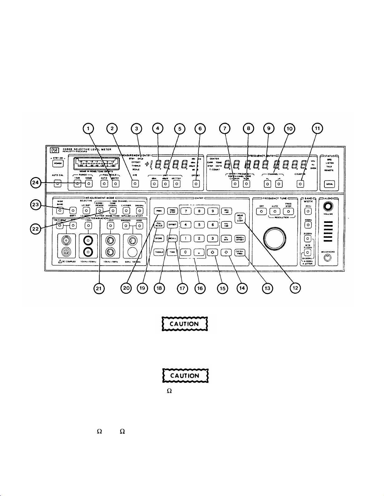
TM 11-6625-3087-12
2-16. NOlSE/TONE MEASUREMENT.
NOTE
To insure optimum performance, keep cable lengths as short as possible. Try to use the
same power source for the Level Meter and the unit under test.
1. On Level Meter, press RECALL (17), number 0 (16), SHIFT (23), then NOISE/TONE (22) push buttons.
The maximum input power must not exceed +27dBm or damage to internal circuitry may
result.
2. On Level Meter, select desired TERMINATION (21).
When using BNC input, use only 75 BNC plugs. Use of other impedance plugs may
damage Level Meter.
NOTE
Only 124 or 135 input may be used at one time.
3. On Level Meter, select desired UNIT of measurement (5).
2-34
Page 55

TM 11-6625-3087-12
4. If an OFFSET is required
Press OFFSET (18).
Enter offset value (16).
Press MEAS CONT (12).
NOTE
Do not change the units after offset has been entered.
5. On Level Meter, select desired sideband CHANNEL (10).
6.Tune the Level Meter to the input signal frequency as follows:
If the carrier frequency is to be used to tune the Level Meter to a message channel, press CARRIER (7), FREQ (20),
and enter the carrier frequency.
If the tone frequency is to be used to tune the Level Meter to a message channel, press TONE (8), FREQ (20), and
enter the tone frequency.
7. Fine tune the Level Meter to the input signal frequency as follows:
Press SHIFT (23).
Press COUNTER (11).
Press CNTR->FREQ (13).
Press SHIFT (23).
8. f an offset was entered in step 4, press OFFSET (6).
9. MEASUREMENT/ENTRY display (4) indicates input signal power level. FREQUENCY/ENTRY display (9) indicates
input signal frequency.
NOTE
Input signal modulation (AM or FM) may cause instability in either display.
10. If MEASUREMENT/ENTRY display is unstable or constantly resets full scale level,
Press AVE (2). If display still unstable, turn AVE off.
NOTE
Use AVE only when necessary because it will decrease the accuracy of this measurement.
Press ENTRY (1).
Press FULL SCALE (19), UP ARROW (15) or DOWN ARROW (14) then MEAS CONT (12) push buttons until
display is stable. Verify OVLD indicator (3) remains off.
If OVLD indicator is on or “OL” appears in MEASUREMENT/ENTRY display, increase
full scale level. If “UL” appears in MEASUREMENT/ENTRY display, decrease full
scale level and/or select 100dB RANGE (24).
Repeat step 7.
NOTE
2-35
Page 56
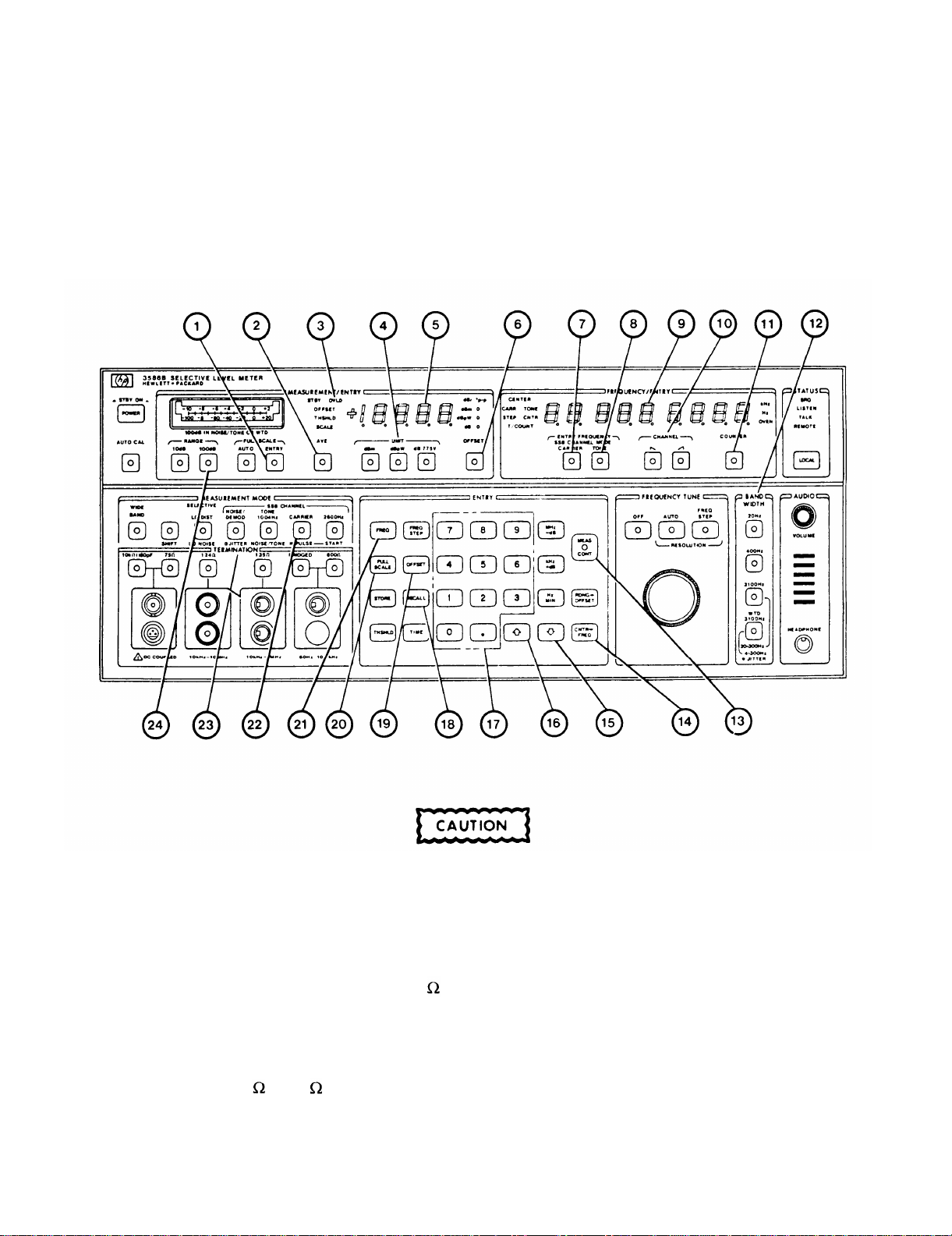
TM 11-6625-3087-12
2-17. CARRIER MEASUREMENT.
NOTE
To insure optimum performance, keep cable lengths as short as possible. Try to use the
same power source for the Level Meter and the unit under test.
1. On Level Meter, press RECALL (18), number 0 (17), then CARRIER (22) push buttons.
The maximum input power must not exceed +27dBm or damage to internal circuitry may
result.
2. On Level Meter, select desired TERMINATION (23).
When using BNC input, use only 75 BNC plugs. Use of other impedance plugs may
damage Level Meter.
NOTE
Only 124 or 135 i nput may be used at one time.
3. On Level Meter, select desired UNIT of measurement (4).
2-36
Page 57

TM 11-6625-3087-12
4. If an OFFSET is required,
Press OFFSET (19).
Enter offset value (17).
Press MEAS CONT (13).
NOTE
Do not change the units after offset has been entered.
5. On Level Meter, select desired sideband CHANNEL (10).
6. Tune the Level Meter to the input signal frequency as follows:
If the carrier frequency is to be used to tune the Level Meter to a message channel, press CARRIER (7), FREQ (21 ),
and enter the carrier frequency.
If the tone frequency is to be used to tune the Level Meter to a message channel, press TONE (8), FREQ (21), and
enter the tone frequency.
7. Fine tune the Level Meter to the input signal frequency as follows:
Press 3100HZ (12).
Press COUNTER (1 1).
Press CNTR->FREQ (14).
Press 20Hz (12).
8. If an offset was entered in step 4, press OFFSET (6).
9. MEASUREMENTLENTRY display (5) indicates input signal power level. FREQUENCY/ENTRY display (9) indicates
input signal frequency.
NOTE
Input signal modulation (AM or FM) may cause instability in either display.
10. If MEASUREMENT/ENTRY display is unstable or constantly resets full scale level,
Press AVE (2). If display still unstable, turn AVE off.
NOTE
Use AVE only when necessary because it will decrease the accuracy of this measurement.
Press ENTRY (1).
Press FULL SCALE (20), UP ARROW (16) or DOWN ARROW (15) then MEAS CONT (13) push buttons until
display is stable. Verify OVLD indicator (3) remains off.
NOTE
If OVLD indicator is on or “OL” appears in MEASUREMENT/ENTRY display, increase
full scale level. If “UL” appears in MEASUREMENT/ENTRY display, decrease full
scale level and/or select 100dB RANGE (24).
Repeat step 7.
2-37
Page 58
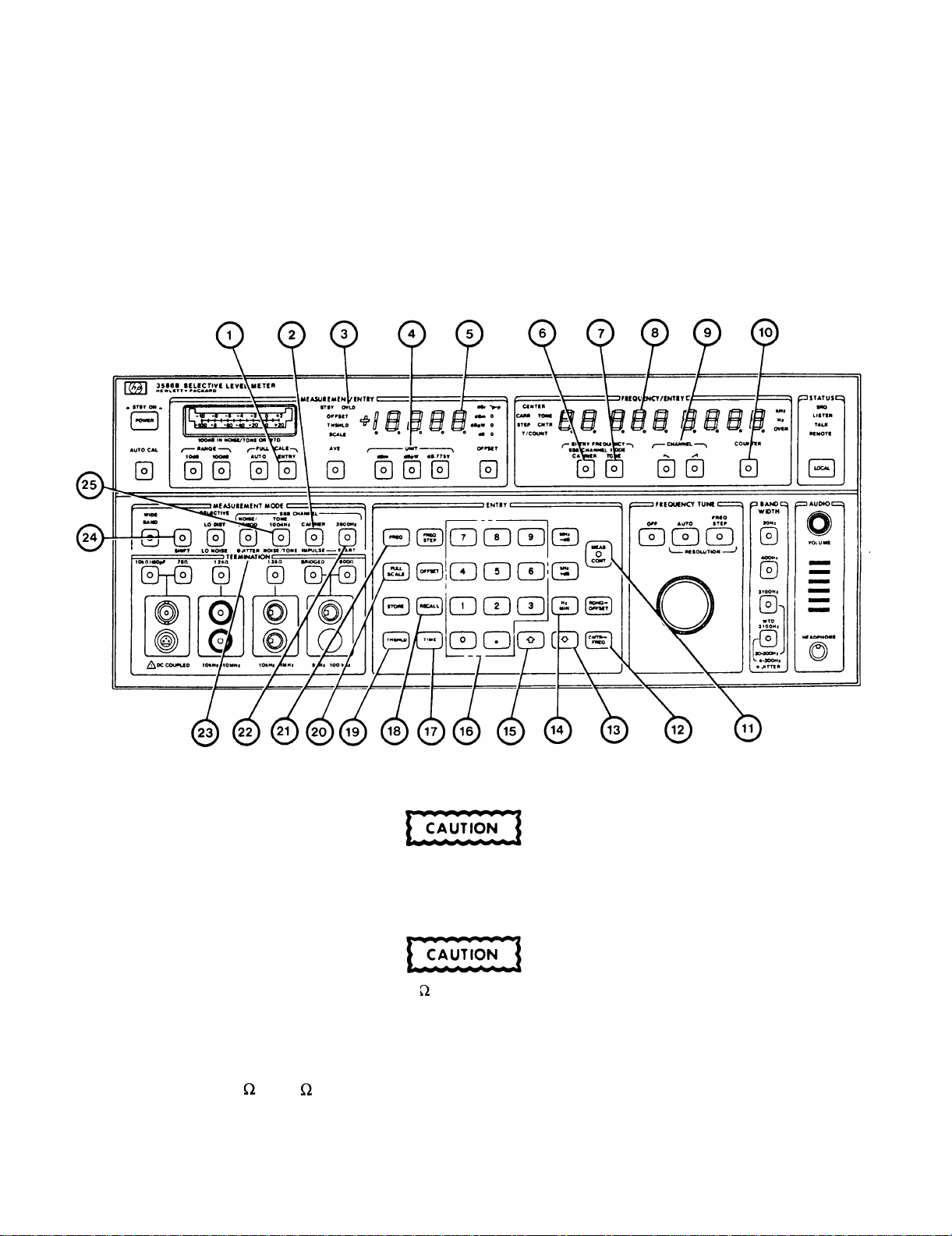
TM 11-6625-3087-12
2-18. IMPULSE MEASUREMENT.
NOTE
To insure optimum performance, keep cable lengths as short as possible. Try to use the
same power source for the Level Meter and the unit under test
1. On Level Meter, press RECALL (18), number 0 (16), SHIFT (24), then IMPULSE (2) push buttons.
The maximum input power must not exceed +27dBm or damage to internal circuitry may
result.
2. On Level Meter, select desired TERMINATION (23).
When using BNC input, use only 75 BNC plugs. Use of other impedance plugs may
damage Level Meter.
NOTE
Only 124 or 135 input may be used at one time.
3. On Level Meter, select desired UNIT of measurement (4).
2-38
Page 59

TM 11-6625-3087-12
4. On Level Meter, enter minimum number of noise spikes to be counted as follows:
Press THSHLD (19).
Enter threshold level ( 16).
Press MEAS CONT(11).
NOTE
Do not change the units after threshold has been entered.
5. On Level Meter, select desired sideband CHANNEL (9).
6. Tune the Level Meter to the input signal frequency as follows:
If the carrier frequency is to be used to tune the Level Meter to a message channel, press CARRIER (6), FREQ (21),
and enter the carrier frequency.
If the tone frequency is to be used to tune the Level Meter to a message channel, press TONE (7), FREQ (21), and
enter the tone frequency.
7. If 1004Hz test tone is on message channel, fine tune Level Meter as follows:
Press NOISE/TONE (25).
Press COUNTER (10).
Press CNTR->FREQ (12).
Press IMPULSE (2).
8. On Level Meter, enter duration as follows:
If counting for a specific time limit, press TIME (17) and enter time in minutes, decimal point, and seconds. Press
MEAS CONT (11).
If counting is to be continuous, press TIME (17) and enter 1000000. Press MIN (14). Verify “CON” appears in
FREQUENCY/ENTRY display (8). Press MEAS CONT (11).
9. Press START (22).
10. MEASUREMENT/ENTRY display (5) indicates input signal power level. FREQUENCY/ENTRY display (8) indicates
time duration (left side) and number of impulse spikes (right side).
NOTE
Input signal modulation (AM or FM) may cause instability in either display.
11. If MEASUREMENT/ENTRY display is unstable or constantly resets full scale level,
Press ENTRY (1),
Press FULL SCALE (20), UP ARROW (15) or DOWN ARROW (13) then MEAS CONT (11) push buttons until
display is stable. Verify OVLD indicator (3) remains off.
NOTE
If OVLD indicator is on or “OL” appears in MEASUREMENT/ENTRY display, increase
full scale level. If “UL” appears in MEASUREMENT/ENTRY display, decrease full
scale level.
2-39
Page 60
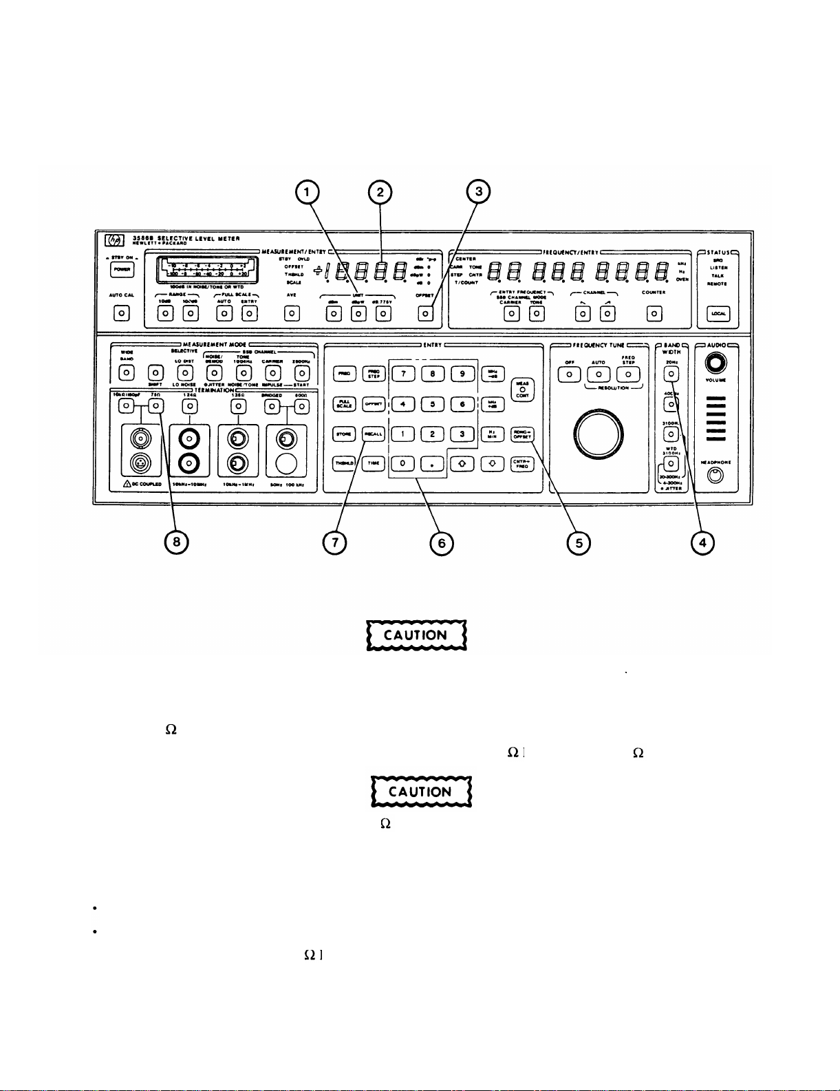
TM 11-6625-3087-12
2-19. NETWORK ANALYSIS MEASUREMENT.
1. On Level Meter, press RECALL (7) then number 0 (6) push buttons.
The maximum input must not exceed ±27dBm or damage to internal circuitry may
result
2. On Level Meter,
Select 75 input (8).
Connect rear panel Fo (0-32 .5MHz) output connector to front panel 75 BNC input using 75 cable supplied.
When using BNC input, use only 75 BNC plugs. Use of other impedance plugs may
damage Level Meter.
3. On Level Meter, select desired UNIT of measurement (1).
4. On Level Meter,
Press 20Hz (4).
Press RDNG—>OFFSET (5).
5. Disconnect cable from front panel 75 BNC input.
6. On Level Meter, press OFFSET (3).
2-40
Page 61

TM 11-6625-3087-12
8. MEASUREMENT/ENTRY display (2) indicates insertion loss of the device connected to BNC input plus output level
shifts due to unequal source and termination impedance.
NOTE
If device impedance is not 75 impedance matching devices must be used between device
to be measured and Level Meter.
Section IV. OPERATION UNDER UNUSUAL CONDITIONS
2-20. OPERATION IN EXTREME HEAT AND EXTREME COLD.
a. Operate the Level Meter only in a temperature range of 0 to +55° C (32 to 131° F).
b. Make sure the filter is clean and at least one inch of open space exists from the rear and side panels.
2-21. OPERATION IN WET WEATHER.
a. The Level Meter will operate normally in 95% relative humidity at +40° C.
b. If the Level Meter has gotten wet, allow it to dry completely before using.
2-22. OPERATION IN SANDY OR DUSTY AREAS.
a. Do not operate the Level Meter in sandy or dusty areas.
2-23. EMERGENCY PROCEDURES.
a. Reduction of power. The Level Meter will operate with power reduced from 90 to 105Vac, 108 to 126Vac, 198 to
231Vac or from 216 to 252Vac. The Level Meter will not operate with any further reduction of power.
2-41/(2-42 Blank)
Page 62

Page 63

CHAPTER 3
ORGANIZATION MAINTENANCE
TM 11-6625-3087-12
Section I.
3-1. COMMON TOOLS AND EQUIPMENT.
Common tools and equipment required for organizational maintenance of Frequency Selective Level Meter AN/USM-490 are
listed in the Maintenance Allocation Chart (MAC) (Appendix B).
3-2. SPECIAL TOOLS, TMDE, AND SUPPORT EQUIPMENT.
There are no special tools, TMDE, or support equipment required.
3-3. REPAIR PARTS.
Repair parts are listed and illustrated in the repair parts and special tools list, TM 11-6625-3087-24P.
3-4. SERVICE UPON RECEIPT OF MATERIAL.
a. Unpacking. Special design reusable packing material inside this shipping carton provides maximum protection for
Level Meter. Avoid damaging carton and packing material during equipment unpacking. Use the following steps for
unpacking Level Meter
Cut and remove paper sealing tape on carton top and open carton.
Grasp Level Meter firmly while restraining shipping carton and lift equipment and packing material vertically.
Place Level Meter and end cap packing material on a suitable flat clean and dry surface.
REPAIR PARTS, SPECIAL TOOLS, TMDE, AND SUPPORT EQUIPMENT
Section Il. SERVICE UPON RECEIPT
Remove end cap packing material while firmly supporting Level Meter.
Remove protective plastic bag from Level Meter. Place desiccant bags back inside protective plastic bag.
Place protective plastic bag and end cap packing material inside shipping carton.
Return shipping carton to supply system.
b. Checking Unpacked Equipment.
Inspect the equipment for damage incurred during shipment. If the equipment has been damaged report the damage
on SF-364, Report of Discrepancy (ROD).
Check the equipment against the packing slip to see if the shipment is complete. Report all discrepancies in
accordance with the instructions of DA Pam 738-750.
Check to see whether the equipment has been modified.
3-5. PRELIMINARY SERVICING AND ADJUSTMENT OF EQUIPMENT.
Perform all items under preparation for use (para 2-5).
a.
b. Perform the turn-on procedures (para 2-6).
c.
Perform operational test (para 3-7).
3-1
Page 64

TM 11-6625-3087-12
Section Ill.
TROUBLESHOOTING
SYMPTOM INDEX
Level Meter
Symptom
1. LEVEL METER WILL NOT TURN-ON
. . . . . . . . . . . . . . . . . . . . . . . . . . . . . . . . . . . . . . . . . . . . . .
2. LEVEL METER QUITS DURING OPERATION . . . . . . . . . . . . . . . . . . . . . . . . . . . . . . . . . . . .
3. FREQUENCY/ENTRY DISPLAY BLANK
4. ERROR MESSAGE PRESENT IN MEASUREMENT/ENTRY DISPLAY
5. FREQUENCY TUNE KNOB WILL NOT CHANGE FREQUENCY
. . . . . . . . . . . . . . . . . . . . . . . . . . . . . . . . . . . . . . . . . . . . . . . . . . . . .
. . . . . . . . . . . . . . . . . .
. . . . . .. . . . . . . . . . . . .
6. AUDIO NONOPERATIVE . . . . . . . . . . . . . . . . . . . . . . . . . . . . .. . . . . . . . . . . . . . . . . . . . . . . . .
7. LEVEL METER WILL NOT MEASURE INPUT SIGNAL
8. OVLD INDICATOR FLASHING
9. OL/UL IN MEASUREMENT/ENTRY DISPLAY
. . . . . . . . . . . . . . . . . . . . . . . . . . .
. . . . . . .. . . . . . . . . . . . . . . .
. . . . . . . . . . . . . . . . . . . . . . . .
3-6. TROUBLESHOOTING TABLE.
Page
3-2
3-3
3-3
3-3
3-3
3-4
3-4
3-4
3-4
Table 3-1 lists common malfunctions which you may find during operation or maintenance of the Level Meter or its
components. You should perform the tests/inspections and corrective actions in the order listed.
This manual cannot list all malfunctions that may occur, nor all tests or inspections and corrective actions. If a malfunction
is not listed or is not corrected by listed corrective actions, notify your supervisor.
Table 3-1. Troubleshooting.
MALFUNCTION
TEST OR INSPECTION
CORRECTIVE ACTION
1. LEVEL METER WILL NOT TURN-ON.
Step 1. Check the fuse and fuseholder cap.
Replace faulty component.
Step 2. Check to see if the power is available at the power receptacle.
Move to a working receptacle.
Step 3. Check power cable.
—
3-2
Replace faulty component.
Notify next higher level of maintenance.
Page 65

Table 3-1. Troubleshooting--Continued.
MALFUNCTION
TEST OR INSPECTION
CORRECTIVE ACTION
2. LEVEL METER QUITS DURING OPERATION
Step 1. Perform malfunction No. 1.
Step 2. Allow the Level Meter to cool and then try operating.
If Level Meter operates normally, check air filter. Clean as required.
If Level Meter does not operate, notify next higher level of maintenance.
3. FREQUENCY/ENTRY DISPLAY BLANK.
Step 1. Check to see if the Level Meter is in WIDEBAND mode.
Select another mode.
TM 11-6625-3087-12
Step 2. Check to see if an ERROR message is present in the MEASUREMENT/ENTRY display.
If error is present, go to malfunction No. 4.
If error is not present, proceed with step 3.
Step 3. Press AUTO CAL push button.
If no calibration error is displayed, recheck operating instructions (para 2-9).
If calibration error is displayed, notify next higher level of maintenance.
4. ERROR MESSAGE PRESENT IN MEASUREMENT/ENTRY DISPLAY.
Step 1. Check to see if error is listed in table 2-2.
Perform required action as listed.
Step 2. Press MEAS CONT push button.
If error disappears, resume normal operation.
If error remains, notify next higher level of maintenance.
5. FREQUENCY TUNE KNOB WILL NOT CHANGE FREQUENCY.
Step 1. Check to see if AUTO or FREQ STEP push buttons are on.
Select proper push button.
Notify next higher level of maintenance.
3-3
Page 66

TM 11-6625-3087-12
Table 3-1. Troubleshooting-Continued.
MALFUNCTION
TEST OR INSPECTION
CORRECTIVE ACTION
6. AUDIO NOT OPERATIVE.
Step 1. Verify in LO DIST, LO NOISE, or NOISE/DEMOD measurement modes.
Make proper selection.
Step 2. Check to see if the audio volume knob is fully CCW.
Increase volume (CW).
3.
Step
7. LEVEL METER WILL NOT MEASURE INPUT SIGNAL.
Perform operational test (para 3-7).
If audio present at end of test, recheck operating instructions.
If audio is missing or weak, notify next higher level of maintenance.
Step 1.
Step
Step 3.
8. OVLD INDICATOR FLASHING.
Step 1. Check full scale setting on Level Meter.
Step 2. Check amplitude of input signal.
9. OL/UL IN MEASUREMENT/ENTRY DISPLAY.
Check to see if the unit under test is on.
Apply power.
2.
Press AUTO CAL push button.
If calibration error is displayed, notify next higher level of maintenance.
If no calibration error is displayed, proceed with step 3.
Perform operational test (para 3-7).
If test passes, recheck operating instructions (para 2-9).
If test fails, notify next higher level of maintenance.
Select AUTO or increase full scale setting.
Decrease amplitude until indicator goes out.
Notify next higher level of maintenance.
3-4
Step 1. Check amplitude of input signal.
Adjust amplitude until indicator goes out.
Step 2. Press AUTO CAL push button.
If no calibration error is displayed, recheck operating instructions.
If calibration error is displayed, notify next higher level of maintenance.
Page 67
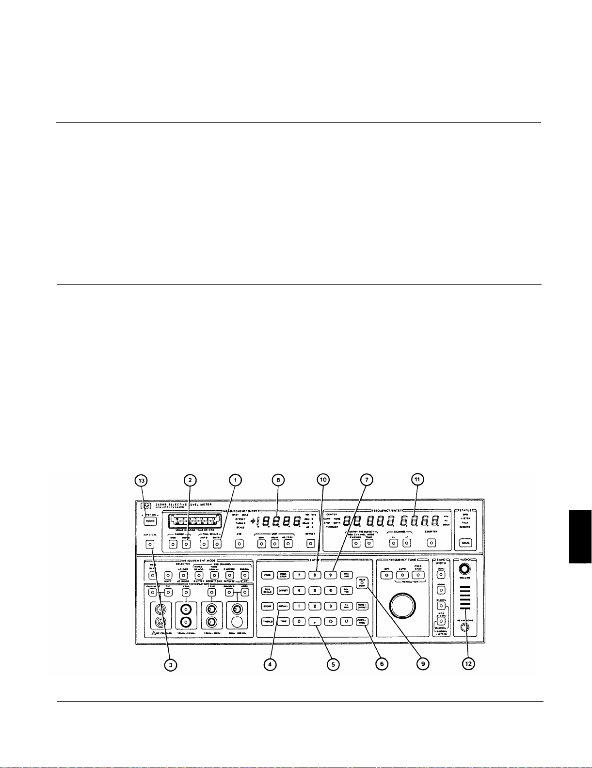
TM 11-6625-3087-12
Section IV.
3-7. OPERATIONAL TEST.
DESCRIPTION
This procedure covers: Test.
INITIAL SETUP
MAINTENANCE PROCEDURES
NOTE
PRELIMINARY PROCEDURES:
Perform turn on procedures (para 2-6).
TEST
1. Press ENTRY (1),100dB (2). Turn AUTO CAL (3) to off. Set full scale to –35dBm.
2. Press RECALL (4), . (decimal point) (5), CNTR—> FREQ (6), and number 9 (7) push buttons.
3. Verify that PASS is shown on the MEASUREMENT/ENTRY display (8)
4. Press MEAS CONT (9),
5. Press RECALL (4), . (decima
6. Verify that PASS is shown on
speaker (12).
7. Press POWER SWITCH (13).
point) (5), CNTR->FREQ (6), and number 8 (10) push buttons.
the FREQUENCY/ENTRY display (11 ) for four tests, and musical tones are heard at the
END OF TASK
3-5
Page 68
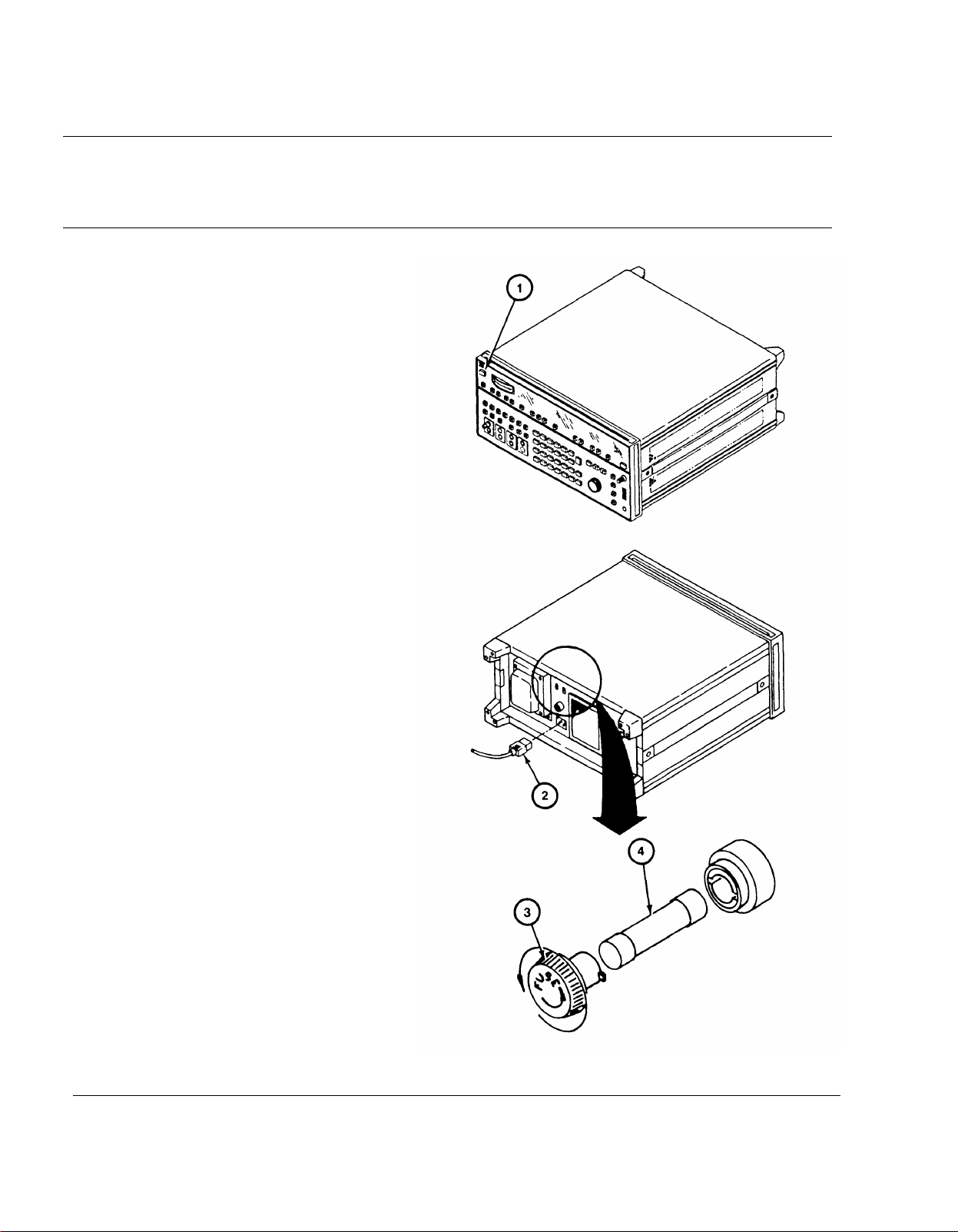
TM 11-6625-3087-12
3-8. REPLACE FUSE.
DESCRIPTION
This procedure covers: Remove. Install.
REMOVE
Working at the front panel, set
1.
POWER switch (1) to STBY.
Working from rear, unplug power cable
2.
(2).
Rotate the fuseholder cap (3)
3.
counterclockwise until it stops.
4.
Pull fuse (4) out of fuseholder cap (3).
INSTALL
Working from rear, insert the fuse (4)
1.
into the fuseholder cap (3) and place it into
the fuseholder body.
2.
Push in and rotate the fuseholder cap
(3) clockwise until it locks.
Replace power cable (2).
3.
Working from front, set POWER
4.
switch (1) to ON.
3-6
END OF TASK
Page 69
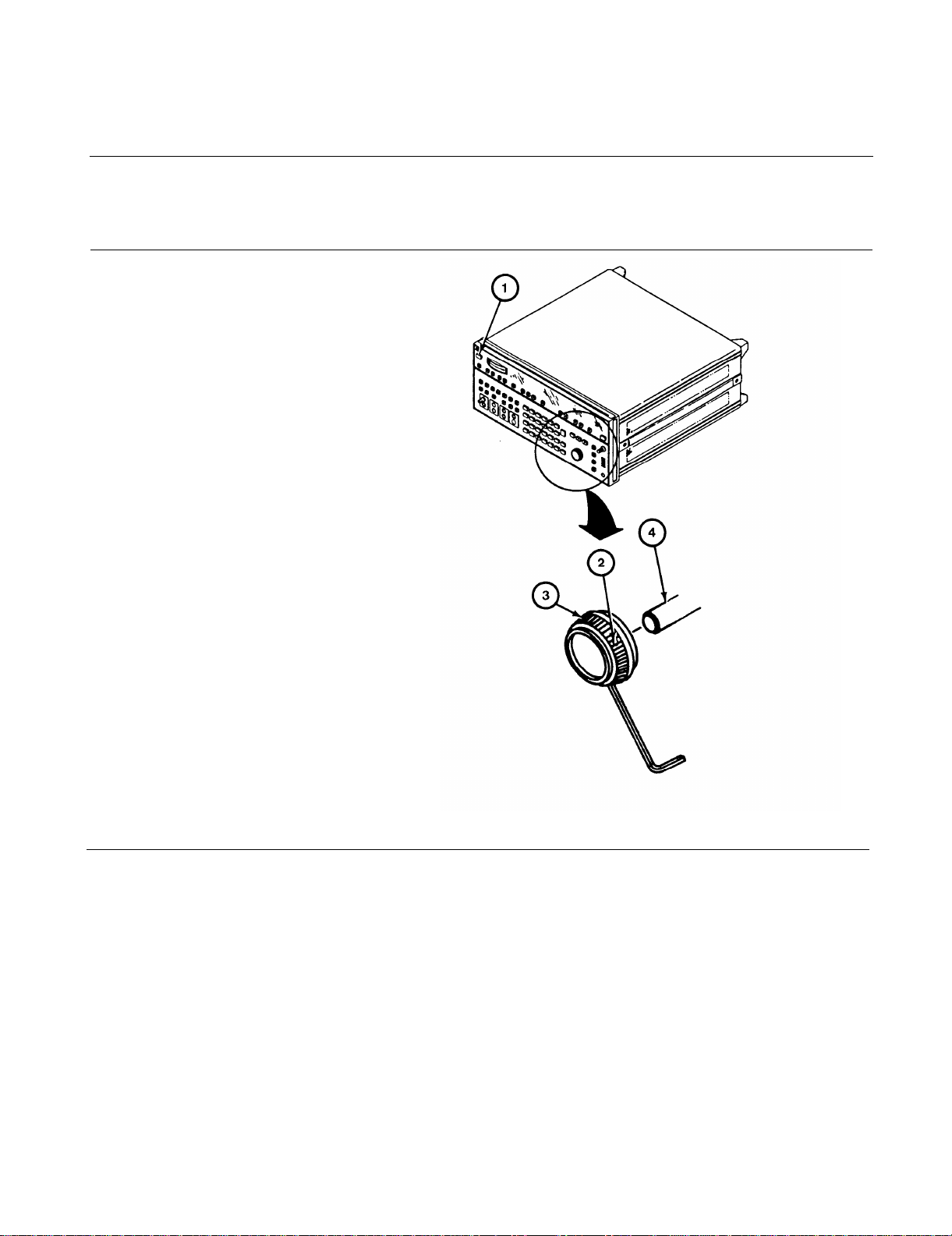
3-9. REPLACE FRONT PANEL CONTROL KNOBS.
DESCRIPTION
This rocedure covers:Remove. Install,
REMOVE
1. Set POWER switch (1) to STBY.
2. Loosen two setscrews (2).
3. Pull knob (3) off shaft (4).
INSTALL
1. Push knob (3) onto shaft (4).
2. Tighten two setscrews (2).
3. Set POWER switch (1) to ON.
TM 11-6625-3087-12
END OF TASK
3-7
Page 70
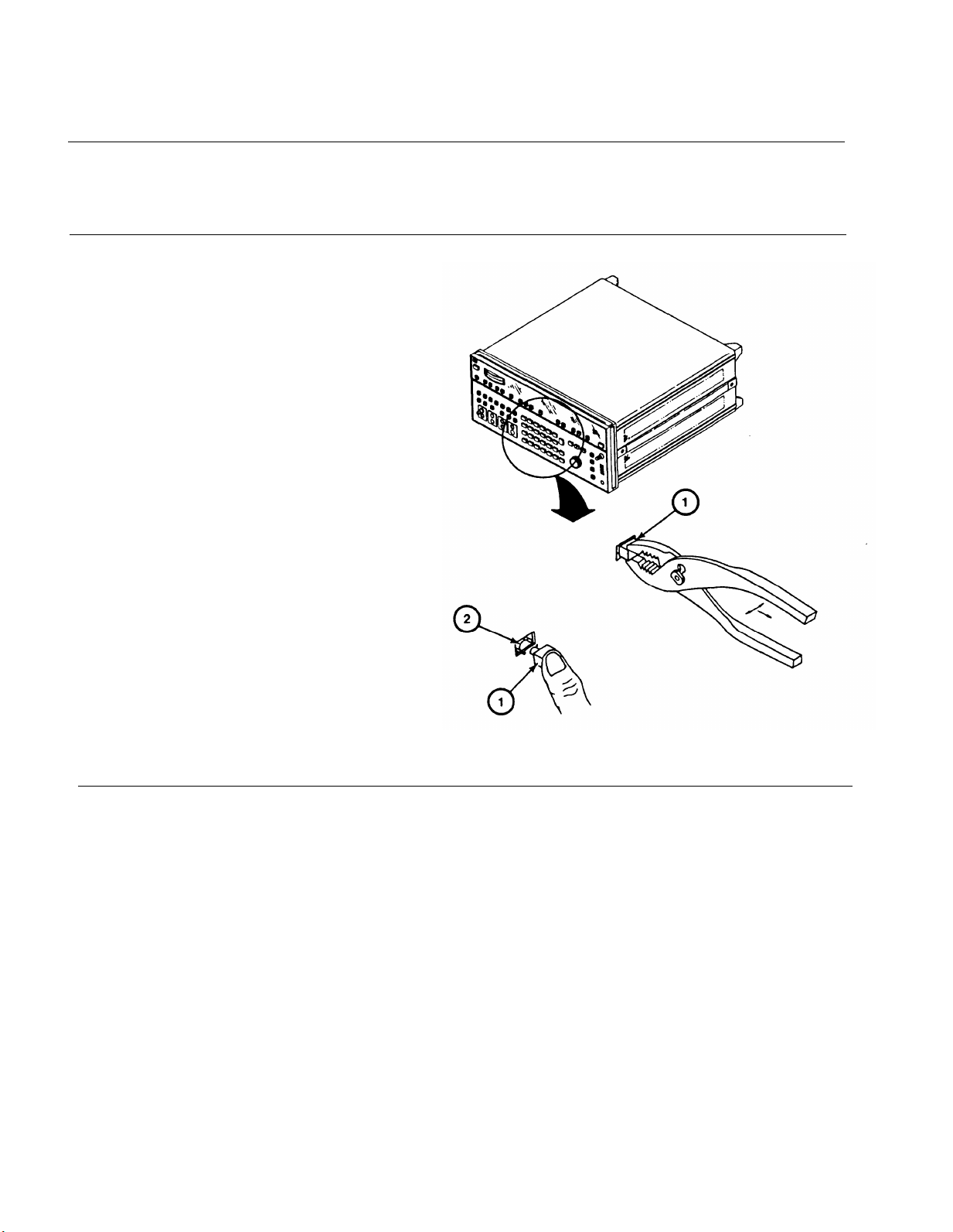
TM 11-6625-3087-12
3-10. REPLACE FRONT PANEL PUSH BUTTONS.
DESCRIPTION
This procedure covers: Remove. Install.
REMOVE
1. CAREFULLY pull push button (1) off
actuator (2) using a small pliers.
INSTALL
1. Align the push button (1) on the switch
actuator (2).
2. Press the new push button (1) until it
seats fully on the switch actuator (2).
3. Check the push button for free
movement and proper operation.
3-8
END OF TASK
Page 71
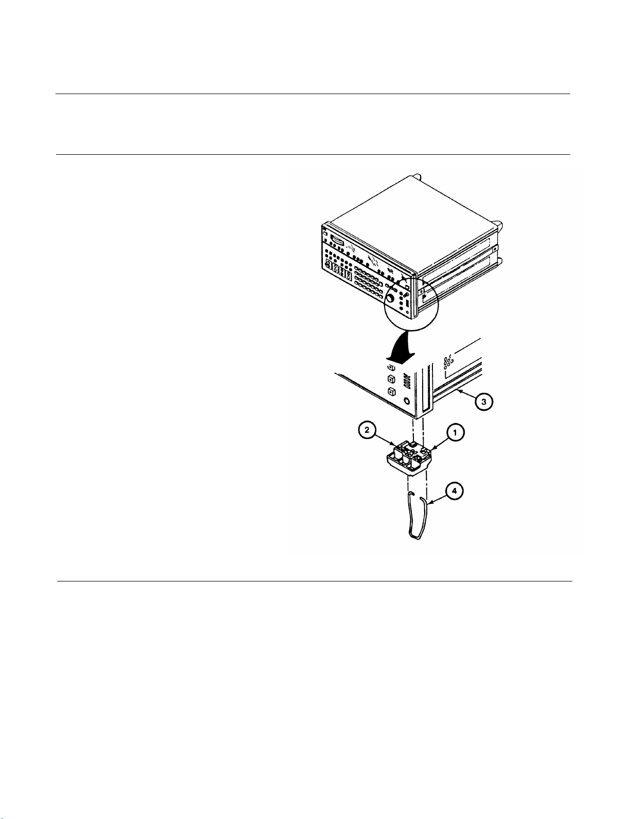
3-11. REPLACE BOTTOM BUMPERS AND TILT STANDS.
DESCRIPTION
This procedure covers: Remove. Install.
REMOVE
1. Place equipment on side.
2. Lift tab (1) and slide bumper (2) inward.
3. Pull bumper (2) out of bottom cover
(3).
4. Remove stand (4) from bumper (2).
INSTALL
1. Replace stand (4) with bend facing away
from bottom cover into bumper (2).
TM 11-6625-3087-12
2. Align three studs on bumper (2) with
three holes on bottom cover (3).
3. Slide bumper (2) outward until it locks.
END OF TASK
3-9
Page 72
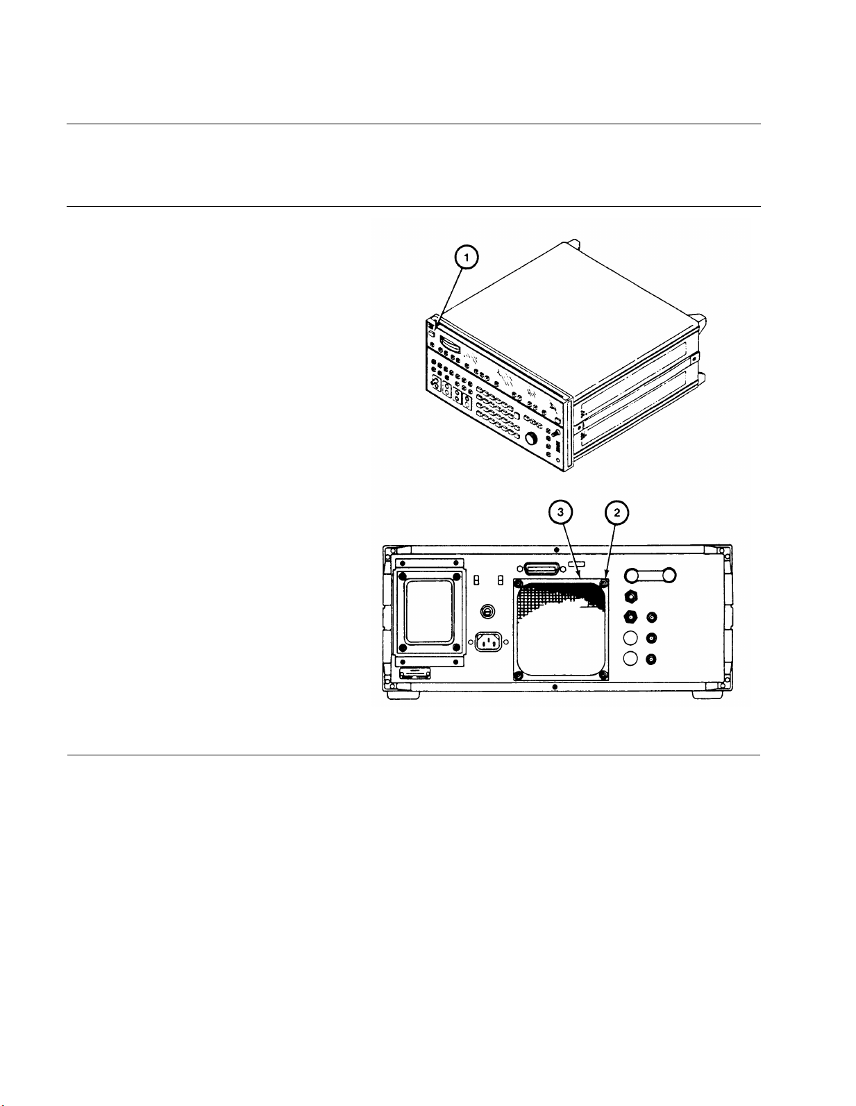
TM 11-6625-3087-12
3-12. REPLACE AIR FILTER.
DESCRIPTION
This procedure covers: Remove. Install.
REMOVE
1. Set POWER switch
2. Working from rear,
nuts (2).
3. Pull off air filter (3).
INSTALL
1. Position air filter (3) on four screws (4).
2. Install four thumb nuts (2).
3. Set POWER switch (1) to ON.
(1) to STBY.
remove four thumb
3-10
END OF TASK
Page 73
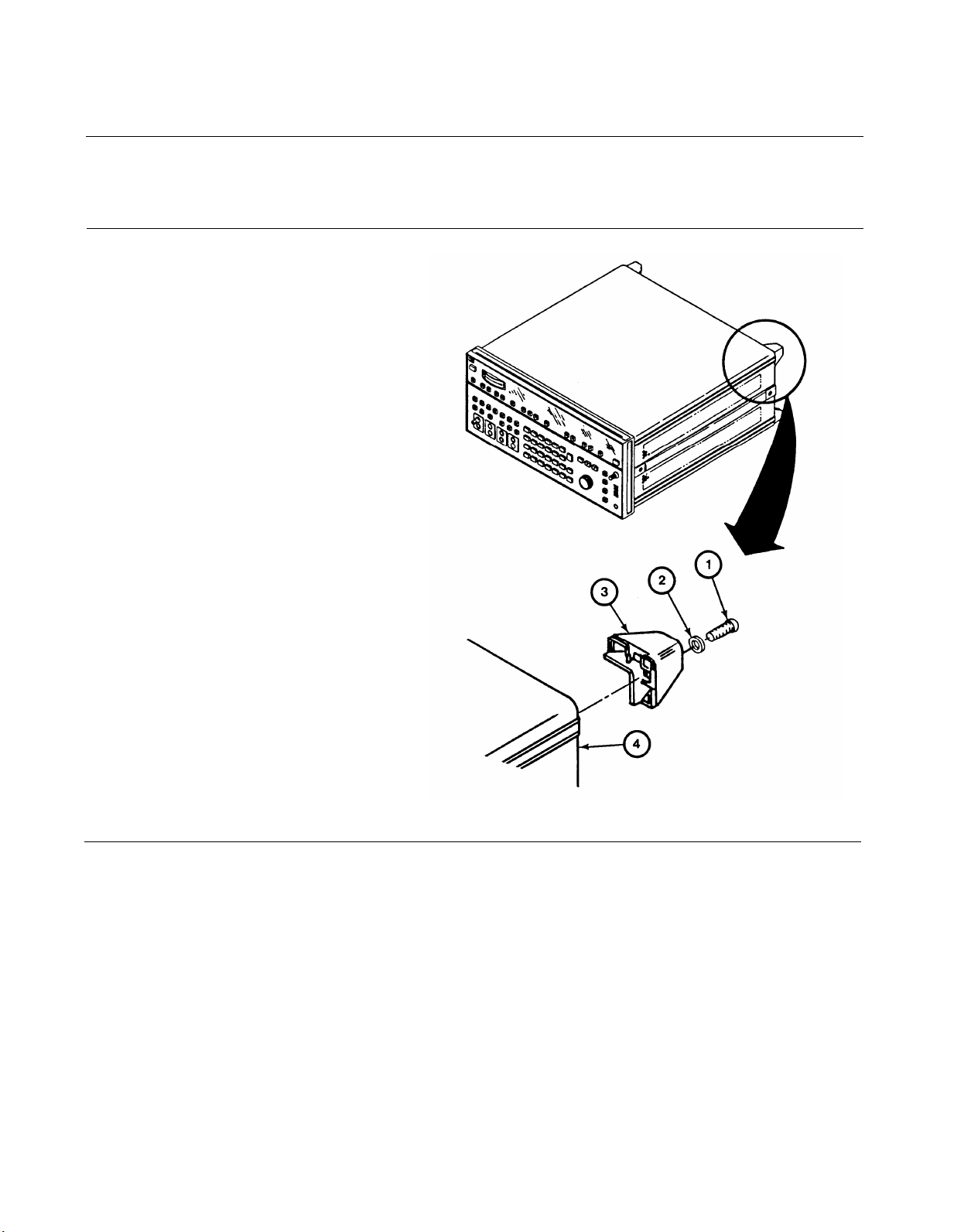
3-13. REPLACE REAR BUMPERS.
DESCRIPTION
This procedure covers: Remove. Install.
REMOVE
1. Working from rear, remove screw (1)
and lock washer (2).
2. Pull bumper (3) from rear frame (4).
INSTALL
1. Working from rear, position bumper (3)
on rear frame (4).
2. Install screw (1) and lock washer (2).
TM 11-6625-3087-12
END OF TASK
3-11
Page 74
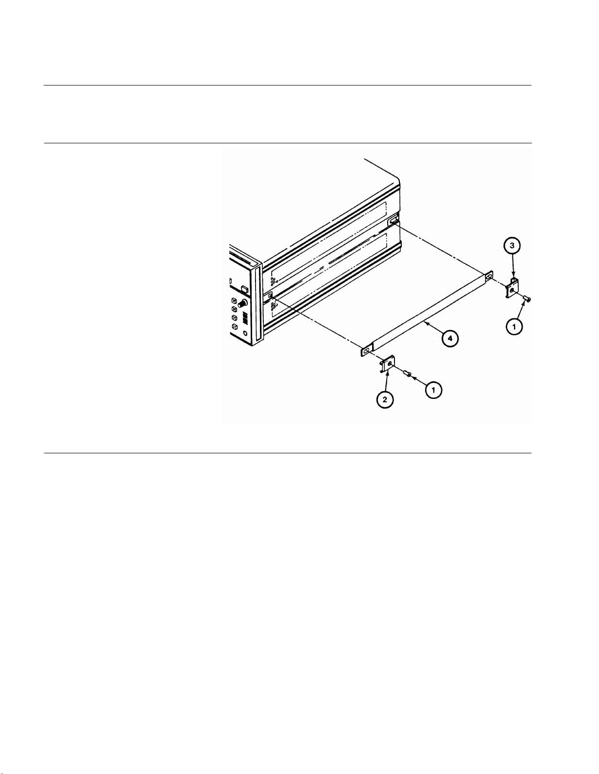
TM 11-6625-3087-12
3-14. REPLACE SIDE HANDLES.
DESCRIPTION
This procedure covers: Remove. Install.
REMOVE
Working from side, remove screws (1).
1.
Remove front (2) and rear (3) retainers.
2.
Remove
3.
INSTALL
Working from side, position side
1.
handle (4), front (2) and rear (3) retainers.
Install screws (1).
2.
side handle (4).
END OF TASK
3-12
Page 75
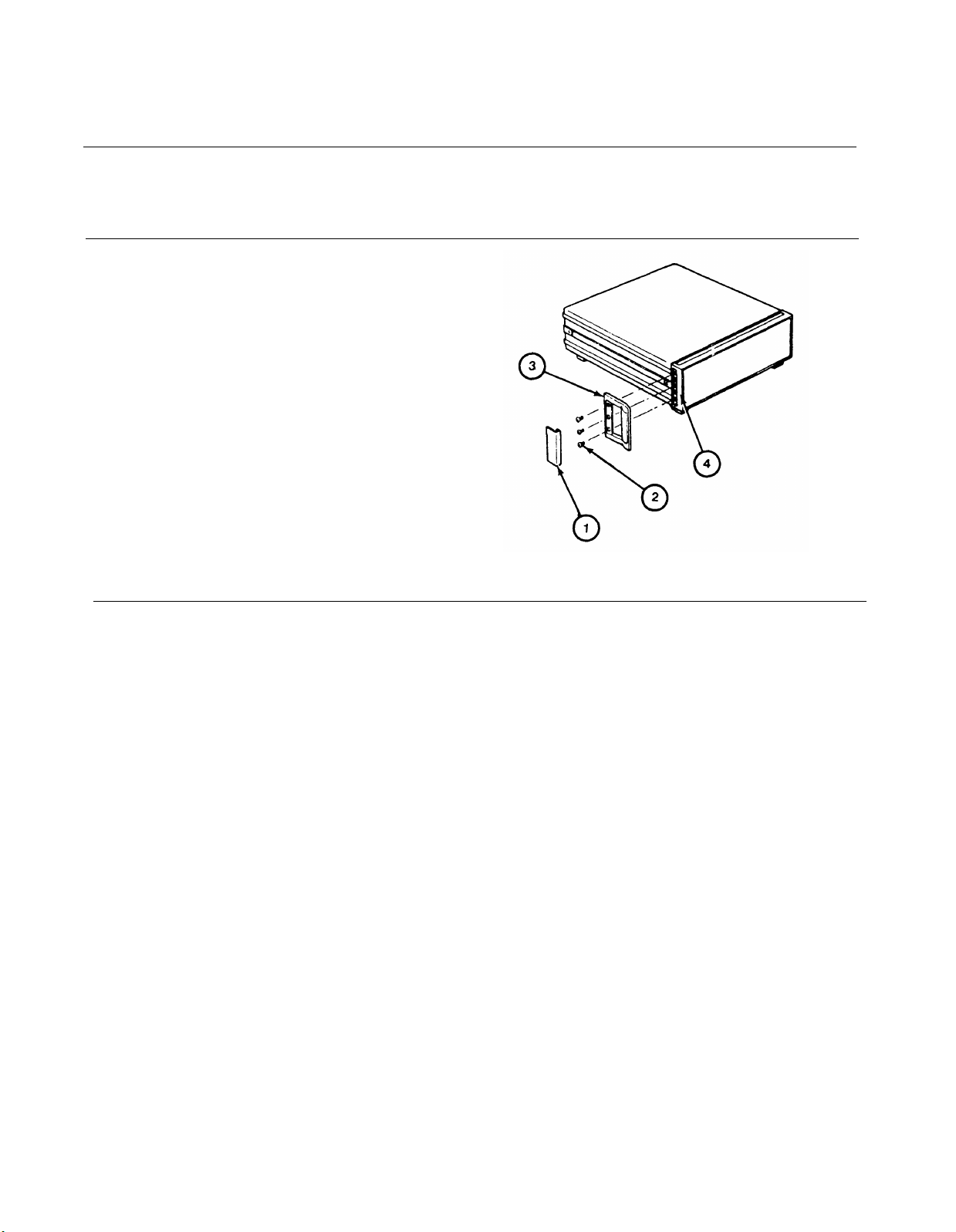
3-15. REPLACE FRONT HANDLES.
DESCRIPTION
This procedure covers: Remove. Install.
REMOVE
TM 11-6625-3087-12
1. Working
2. Remove screws (2).
3. Remove front handle
INSTALL
1. Working from side, position side handle
(3) on front frame (4).
2
Install screws (2).
3. Install trim (1).
from side, remove trim (1).
(3).
END OF TASK
3-13
Page 76

TM 11-6625-3087-12
Sect
on V.
3-16. PACKAGING.
Package level meter in original shipping container. Refer to SB 38-100 for preservation, packaging, packing and marking
materials
3-17. ADMINISTRATWE STORAGE.
Refer to TM 740-90-1 for administrative storage procedures.
3-18. ENVIRONMENT.
The level meter should be stored in aclean, dry environment. In high humidity environments, protect the level meter from
temperature variations that could cause internal condensation.
shipping and storage:
Temperature . . . . . . . . . . . . . . . . . .
Relative Humidity
Altitude . . . . . . . . . . . . . . . . . . . . . . . . . . . . . . .
. . . . . . . . . . . . . . . . . . . . . . . . . . . . . . . . . . . . . . . . . . . . . . . . . . . . . . . . . . . . . . . . . . . . . . . . . . . . . . . . . . . . . . . . . . . . . . . . .
PREPARATION FOR STORAGE OR SHIPMENT
The following environmental conditions apply to both
-40° C to +75° C (-40” F to +158° F)
less than 95%
less than 15,300 meters (50,000 feet)
3-14
Page 77

TM 11-6625-3087-12
APPENDIX A
REFERENCES
A-1. SCOPE.
This appendix lists all forms, field manuals, technical manuals, and miscellaneous publications referenced in this manual.
A-2. FORMS.
Recommended Changes to Publications and Blank Forms
Recommended Changes to Equipment Technical Manuals
Discrepancy in Shipment Report (DISREP)
Report of Discrepancy (ROD)
Quality deficiency report
A-3. TECHNICAL MANUALS.
The Army Maintenance Management System (TAMMS)
Procedures for Destruction of Electronics Materiel to prevent Enemy Use (Electronics Command) . . . . TM 750-244-2
Organizational, Direct Support, and General Support Repair Parts and Special Tools List,
for Frequency Selective Level Meter AN/USM-490
Administrative storage procedures
A-4. MISCELLANEOUS.
Consolidated Index of Army Publications and Blank Forms
First Aid for Soldiers
Safety Precautions for Maintenance of Electrical/Electronic Equipment
Abbreviations for Use on Drawings, Specifications, Standards and in Technical Documents . . . . . . . . . . . . . . . . . . . . MIL-STD- 12
Preservation, Packaging, Packing, and Marking Materials, Supplies and Equipment Used by the Army . . . . . . . . . . . . . SB 38-100
. . . . . . . . . . . . . . . . . . . . . . . . . . . . . . . . . . . . . . . . . . . . . . . . . . . . . . . . . . . . . . . . . . . . . . . . . . . . . . . . . . . . . . . . . . . . . . . . . . . . . . . . . . . . . . . . . . . . . . . . . .
. . . . . . . . . . . . . . . . . . . . . . . . . . . . . . . . . . . . . . . . . . . . . . . . . . . . . . . . . . . . . . . . . . . . . . . . . . . . . . . . . . . . . . . . . . . . . . . . .. . . . . . . .
. . . . . . . . . . . . . . . . . . . . . . . . . . . . . . . . . . . . . . . . . . . . . . . . . . . . . . . . . . . ... . . . . . . . . . . . . . . . . . . . . . . . . . . . . . . . . . . . . . . . . . . . . . . . . . . .
.. . . . . . . . . . . . . . . . . . . . . . . . . . . . . . . . . . . . . . . . . . . . . . . . TM740-90-1
. . . . . . . . . . . . . . . . . . . . . . . . . . . . . . . . . . . . . . . . . . . . . . . . . . . . . . . . . . . . . . . . . . . . . . . . . . . . . . . . . . . . . . .
. . . . . . . . . . . . . . . . . . . . . . . . . . . . . . . . . . . . . . . . . . . . . . . . . . . . . . . . . . . . . . . . . . .
. . . . . . . . . . . . . . . . . . . . . . . . . . . . . . . . . . . . . . . . . . . . . . . . . . . . . . . . . . . . . . . . .
. . . . . . . . . . . . . . . . . . . . . . . . . . . . . . . . . . . . . . . . . . . . . . . . . . . . . . . . . . . . . . . . .
. . . . . . . . . . . . . . . . . . . . . . . . . . . . . . . . . . . . . . . . . . . . . . . . . . . . . . . . . . . . .
. . . . . . . . . . . . . . . . . . . . . . . . . . . . . . . . . . . . . . . . . . . . . . . . . . . . . . . . . . . . . . . . .
. . . . . . . . . . . . . . . . . . . . . . . . . . . . . . . . . . . . . . . . . . . . . . . . . . . . . . . . . .
TM 11-6625-3087-24P
DA Form 2028
DA Form 2028-2
Form SF 361
Form SF 364
Form SF 368
DA Pam 738-750
DA Pam 310-1
FM 21-11
TB 385-4
A-1/(A-2 Blank)
Page 78

Page 79

TM 11-6625-3087-12
APPENDIX B
MAINTENANCE ALLOCATION CHART (MAC)
INTRODUCTION
The Army Maintenance System MAC
This introduction provides a general explanation of all maintenance and repair function authorized at the two
maintenance levels under the Two-Level Maintenance System concept.
This MAC (immediately following the introduction) designates overall authority and responsibility for the
performance of maintenance functions on the identified end item or component. The application of the
maintenance functions to the end item or component levels, which are shown on the MAC in column (4) as:
Field – includes two columns, Unit maintenance and Direct Support maintenance. The Unit maintenance
column is divided again into two more subcolumns, C for Operator or Crew and O for Unit maintenance.
Sustainment – includes two subcolumns, general support (H) and depot (D).
The tools and test equipment requirements (immediately following the MAC) list the tools and test equipment
(both special tools and common tool sets) required for each maintenance function as referenced from the MAC.
The remarks (immediately following the tools and test equipment requirements) contain supplemental instructions
and explanatory notes for a particular maintenance function.
Maintenance Functions
Maintenance functions are limited to and defined as follows:
1. Inspect. To determine the serviceability of an item by comparing its physical, mechanical, and/or
electrical characteristics with established standards through examination (e.g. by sight, sound, or
feel). This includes scheduled inspection and gagings and evaluation of cannon tubes.
2. Test. To verify serviceability by measuring the mechanical, pneumatic, hydraulic, or electrical
characteristics of an item and comparing those characteristics with prescribed standards on a
scheduled basis, i.e., load testing of lift devices and hydrostatic testing of pressure hoses.
3. Service. Operations required periodically to keep an item in proper operating condition; e.g., to clean
(includes decontaminate, when required), to preserve, to drain, to paint, or to replenish fuel,
lubricants, chemical fluids, or gases. This includes scheduled exercising and purging of recoil
mechanisms. The following are examples of service functions:
a. Unpack. To remove from packing box for service or when required for the performance
of maintenance operations.
b. Repack. To return item to packing box after service and other maintenance operations.
c. Clean. To rid the item of contamination.
d. Touch up. To spot paint scratched or blistered surfaces.
e. Mark. To restore obliterated identification.
4. Adjust. To maintain or regulate, within prescribed limits, by bringing into proper position, or
by setting the operating characteristics to specified parameters.
5. Align. To adjust specified variable elements of an item to bring about optimum or desired
performance.
Change 1 B-1
Page 80

TM 11-6625-3087-12
APPENDIX B
MAINTENANCE ALLOCATION CHART (MAC)
6. Calibrate. To determine and cause corrections to be made or to be adjusted on instruments of
test, measuring, and diagnostic equipment used in precision measurement. Consists of comparisons
of two instruments, one of which is a certified standard of known accuracy, to detect and adjust any
discrepancy in the accuracy of the instrument being compared.
7. Remove/install. To remove and install the same item when required to perform service or
other maintenance functions. Install may be the act of emplacing, seating, or fixing into
position a spare, repair part, or module (component or assembly) in a manner to allow the
proper functioning of an equipment or system.
8. Paint. To prepare and spray color coats of paint so that the ammunition can be identified
and protected. The color indicating primary use is applied, preferably, to the entire exterior surface
as the background color of the item. Other markings are to be repainted as original so as to retain
proper ammunition identification.
9. Replace. To remove an unserviceable item and install a serviceable counterpart in its place
“Repair” is authorized by the MAC and assigned maintenance level is shown as the third position
code of the Source, Maintenance and Recoverability (SMR) code.
10. Repair. The application of maintenance services, including fault location/troubleshooting,
removal/installation, disassembly/assembly procedures and maintenance actions to identify troubles
and restore serviceability to an item by correcting specific damage, fault, malfunction, or failure in a
part, subassembly, module (component or assembly), end item or system.
NOTE
The following definitions are applicable to the “repair” maintenance function:
Services. Inspect, test, service, adjust, align, calibrate, and/or replace.
Fault location/troubleshooting. The process of investigating and detecting the case of equipment
malfunctioning; the act of isolating a fault within a system or Unit Under Test (UUT).
Disassembly/assembly. The step-by-step breakdown (taking apart) of a spare/functional group coded
item to the level of its least component, that is assigned an SMR code for the level of maintenance
under consideration (i.e., identified as maintenance significant).
Actions. Welding, grinding, riveting, straightening, facing, machining, and/or resurfacing.
11. Overhaul. That maintenance effort (service/action) prescribed to restore an item to a
completely serviceable/operational condition as required by maintenance standards in appropriate
technical publications. Overhaul is normally the highest degree of maintenance performed by the
Army. Overhaul does not normally return an item to like new condition.
12. Rebuild. Consists of those services/actions necessary for the restoration of unserviceable
equipment to a like new condition in accordance with original manufacturing standards. Rebuild is
the highest degree of material maintenance applied to Army equipment. The rebuild operation
includes the act of returning to zero those age measurements (e.g., hours/miles) considered in
classifying Army equipment/components.
B-2 Change 1
Page 81

TM 11-6625-3087-12
APPENDIX B
MAINTENANCE ALLOCATION CHART (MAC)
Explanation of Columns in the MAC
Column (1) Group Number, Column (1) lists FGC numbers, the purpose of which is to identify maintenance
significant components, assemblies, subassemblies, and modules with the Next Higher Assembly (NHA).
Column (2) Component/Assembly. Column (2) contains the item names of components, assemblies,
subassemblies, and modules for which maintenance is authorized.
Column (3) Maintenance Function. Column (3) lists the functions to be performed on the item listed in column
(2). (For a detailed explanation of these functions, refer to “Maintenance Functions” outlined above).
Column (4) Maintenance Level. Column (4) specifies each level of maintenance authorized to perform each
function listed in column (3), by indicating work time required (expressed as manhours in whole hours or
decimals) in the appropriate subcolumn. The work time figure represents the active time required to perform that
maintenance function at the indicated level of maintenance. If the number or complexity of the tasks within the
listed maintenance function varies at different maintenance levels, appropriate work time figures are to be shown
for each level. The work time figure represents the average time required to restore an item (assembly,
subassembly, component, module, end item or system) to a serviceable condition under typical field operating
conditions. This time includes preparation time (including any necessary disassembly/assembly time),
troubleshooting/fault location time, and quality assurance time in addition to the time required to perform the
specific tasks identified for the maintenance functions authorized in the MAC. The symbol designations for the
various maintenance levels are as follows:
C Operator or Crew maintenance
O Unit maintenance
F Direct Support maintenance
L Specialized Repair Activity
H General Support maintenance
D Depot maintenance
The “L” maintenance level is not included in column (4) of the MAC. Functions
to this level of maintenance are identified by work time figure in the “H” column
of column (4), and an associated reference code is used in the REMARKS column (6).
This code is keyed to the remarks and the SRA complete repair application is explained
there.
Column (5) Tools and Equipment Reference Code. Column (5) specifies, by code, those common tool sets (not
individual tools), common Test, Measurement and Diagnostic Equipment (TMDE), and special tools, special
TMDE and special support equipment required to perform the designated function. Codes are keyed to the entries
in the tools and test equipment table.
Column (6) Remarks Code. When applicable, this column contains a letter code, in alphabetical order, which is
keyed to the remarks table entries.
Field:
Sustainment:
NOTE
Change 1 B-3
Page 82
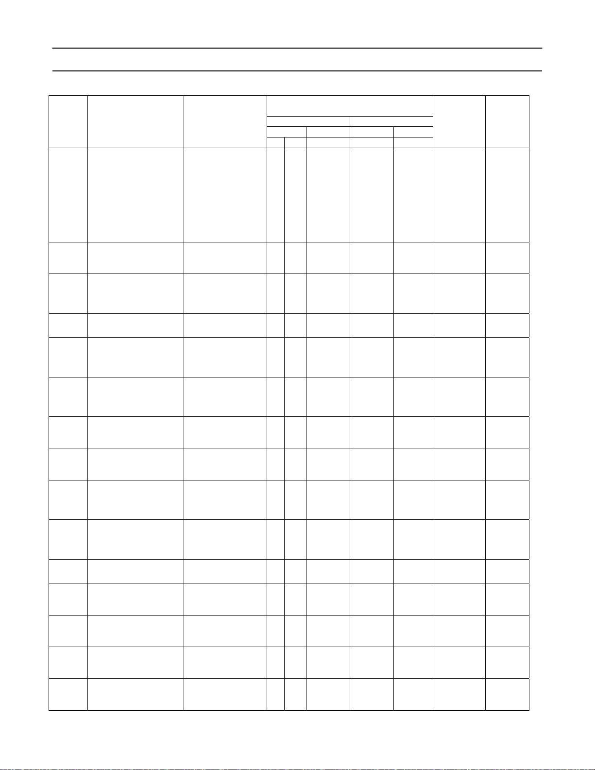
TM 11-6625-3087-12
APPENDIX B
MAINTENANCE ALLOCATION CHART (MAC)
(1)
GROUP
NUMBER
00 Frequency Selective Level
01 Circuit Card Assembly A1
02 Circuit Card Assembly A2
03 Circuit Card Assembly A4
04 Circuit Card Assembly A5
05 Circuit Card Assembly A10
06 Circuit Card Assembly A11
07 Circuit Card Assembly A15
08 Circuit Card Assembly A16
09 Circuit Card Assembly A20
10 Circuit Card Assembly A21
11 Circuit Card Assembly A22
12 Circuit Card Assembly A40
13 Circuit Card Assembly A50
14 Circuit Card Assembly A60
COMPONENT/ASSEMBLY
Meter, AN/USM-490
(Input Multiplexer)
(Input Amp)
(Broadband Pwr/Cal/Overld)
(Input Mixer)
(Second Mixer)
(Second LO)
(Tracking Output)
(10MHz Freq Ref)
(IF Gain/Det)
(Analog-Digital Conv)
(Frequency Reference)
(Step Loop)
(Controller)
Table 1. MAC for Frequency Selective Level Meter, AN/USM-490
(2)
(IF Filter)
(3)
MAINTENANCE
FUNCTION
INSPECT
TEST
SERVICE
INSPECT
TEST
ADJUST
CALIBRATE
REPAIR
REPAIR
REPAIR
INSPECT
TEST
REPAIR
INSPECT
TEST
REPAIR
INSPECT
TEST
REPAIR
INSPECT
TEST
REPAIR
INSPECT
TEST
REPAIR
INSPECT
TEST
REPAIR
INSPECT
TEST
REPAIR
INSPECT
TEST
REPAIR
INSPECT
TEST
REPAIR
INSPECT
TEST
REPAIR
INSPECT
TEST
REPAIR
INSPECT
TEST
REPAIR
INSPECT
TEST
REPAIR
INSPECT
TEST
REPAIR
UNIT DS GS DEPOT
C O F H D
0.5
0.5
0.5
1.0
0.2
0.2
0.2
0.2
0.2
0.1
0.2
0.2
0.1
0.2
0.2
0.2
0.2
0.2
(4)
MAINTENANCE LEVEL
FIELD SUSTAINMENT
1.0
1.0
1.0
1.0
8.2
0.5
1.0
0.5
0.5
0.5
1.0
0.5
1.0
0.5
1.0
0.5
1.0
0.5
1.0
0.5
1.0
0.5
1.0
0.5
1.0
0.5
1.0
0.5
1.0
0.5
1.0
10.0
2
2
2
2
2
2
2
2
2
2
2
2
2
2
TOOLS AND
EQUIPMENT
2, 5, 6, 7-43
2-14,1618,25,40-42
2,5-7,14,16-
18,25-42
2,4,6,8,12,17,
21,25
2,3,18,21
2,4-8,13,17-
18,21,25
2,3,57,12,18,21,25
2,4-6,8-12,17
2,3,5,6,12
2,4-6,810,12,17,18,25
2,3,5,6,10,12,1
2,4,5,8,11,12,1
4,18,18,25
2,3,5,6,11,12,1
4,17,25,33
2,4,5,6,8,10,
12,16,17
2,3,5,12
2,4,5,8,12,16,
2,3,5,12
6,8,10,12,16,
2,3,5,12
2,4,5,8,11,12,
14,16,17
2,3,5,6,11,12,1
4.16,33
2,4,5,6,8,12,17
2,3,5,6,12
2,4-6,8,
12-16,17
2,3,5,12-17
2,4-6,8-10,
12-16,17
2,3,5,12-16
2,4,5,8,10,12,1
4,16,17
2,3,5,12,14,16
2,4,5,8,12,16,
2,3,5,12
(5)
1
1
1
2
2-43
1
2-43
8,25
17
2,4-
17
16
(6)
REMARKS
1
2
3
4
5
6
7
8
9
5
5
5
5
5
5
5
5
5
5
5
5
5
5
B-4 Change 1
Page 83
TM 11-6625-3087-12
APPENDIX B
MAINTENANCE ALLOCATION CHART (MAC)
(1)
GROUP
NUMBER
15 Circuit Card Assembly A70
16 Circuit Card Assembly A98
17 Circuit Card Assembly A99
COMPONENT/ASSEMBLY
(2)
(Impairments B)
(Switch/Didplay)
(Motherboard)
(3)
MAINTENANCE
FUNCTION
INSPECT
TEST
REPAIR
REPAIR
INSPECT
TEST
REPAIR
INSPECT
TEST
REPAIR
UNIT DS GS DEPOT
C O F H D
0.2
0.2
0.2
Table 2. Tools and Test Equipment for Frequency Selective Level Meter, AN/USM-490
(1)
TOOLS OR
TEST
EQUIPMENT
(2)
MAINTENANCE
LEVEL
NOMENCLATURE
(3)
REF CODE
1 O Tool Kit 5180-00-064-5178 TK-101/G
2 F,D Tool Kit 5180-01-195-0855 JTK-17
3 F,D Printed Circuit Repair
kit or equiv for use on
non-multi-layer CCA
4 F,D Transistor Test Set 6625-00-159-2263 TS-1836C/U
5 F,D Circuit Card Extender
Kit
6 F,D Synthesizer/Level
Generator
7 F,D Frequency Synthesizer 6625-01-107-8152 3325A (TMDE
8 F,D Oscilloscope 6625-01-034-3269 5440 (AN/GSM-286)
9 F,D Plug-In Unit 4931-01-008-1478 5S14N
10 F,D Spectrum Analyzer 6625-01-079-9495 AN/USM-489(V)/1
11 F,D Signal Generaror 6625-01-233-8615 SG-1207/U
12 F,D Digital Multimeter 6625-01-042-7415 3455A (TMDE
13 F,D Power Meter 6625-01-191-7679 AN/USM-491
14 F,D Thermistor Mount 5985-01-257-9470 478A (AN/GSM-
15 F,D Tester, Digital Circuit 6625-01-068-8641 TS-3791/U
16 F,D Counter, Frequency 6625-00-531-4752 5345A
17 F,D Voltage, DC Source 332 (AN/GSM-286)
18 F,D Attenuator 5985-00-957-1860 355D
(4)
MAINTENANCE LEVEL
FIELD SUSTAINMENT
2
0.5
1.0
0.5
1.0
2
0.5
1.0
TOOLS AND
EQUIPMENT
2,4-
6,8,9,12,15,16
2,3,5,6,12
2,8,12
2,3,12
(4)
NATIONAL
STOCK
TOOL NUMBER
NUMBER
5999-00-757-7042 MK-772/U
6625-01-132-1715 03586-84401(28480)
6625-01-151-8424 3335A-001
(AN/GSM-286)
A041022) (May use
(AN/GSM-286)
(AN/GSM-286)
(With CAL sheet)
(5)
REMARKS
(5)
D040015)
HP 3478A)
286)
(6)
5
5
Change 1 B-5
Page 84
TM 11-6625-3087-12
APPENDIX B
MAINTENANCE ALLOCATION CHART (MAC)
19 F,D 100 KHz Low Pass
Filter
20 F,D 10 MHz Low Pass
Filter
21 F,D 75 Ohm Directional
Bridge
22 F,D 124 Ohm Return Loss
Coupler
23 F,D 75 Ohm 0.5V Thermal
Converter
24 F,D Frequency Doubler G-3 (15542)
25 F,D 50/75 Ohm Minimum
Loss Pad (2 each)
26 F,D BNC “T”, 2 each 5935-00-103-7571 31-2208-1020
27 F,D Adapter, 2 each 5935-01-183-3404 29PP110-1 (24931)
28 F,D Adapter, 2 each 29JJ124-1 (24931)
29 F,D WECO 310 Plug to (f)
BNC Adapter (5each)
30 F,D (m) BNC to single
banana jack adapter (2
each)
31 F,D 600 OHM Feed Thru 6695-01-209-3205 7916916
32 F,D Large WECO to (f)
BNC adapter (3each)
33 F,D 600 Ohm Balance
Testing Apparatus
34 F,D 75 ohm to balanced
124 ohm matching pad
35 F,D 75 ohm to balanced
135 ohm matching pad
36 F,D 75 ohm to balanced
600 ohm matching pad
37 F,D 135 ohm balance
testing apparatus
38 F,D Power combiner 6695-01-209-1655 7916899
39 F,D 124 ohm balance
testing apparatus
40 F,D Attenuator 5985-00-763-7326 7910807
41 F,D High Impedance Probe 7420-00-623-3211 1120A
42 F,D Low Frequency
Spectrum Analyzer
43 F,D RF Amplifier 5996-01-208-8517 QB-188-2 (55027)
5915-01-212-4457 F2172 (19615)
5915-01-212-4456 F2171 (19615)
6625-01-132-7197 8721A/008
(28480)
5061-1137
(28480)
6625-01-213-0421 11051A/003 (28840)
(With CAL sheet)
6625-01-127-0094 11852A (28480)
(02660)
6625-00-107-8287 2798 (05276)
5935-00-665-6544 UG1090U
WECO 372 (14949)
6695-01-209-1651 7916897
6695-01-209-1652 7916895
6695-01-209-1653 7916896
6695-01-209-1654 7916898
6695-01-209-3206 7916894
6695-01-209-3207 7916893
6625-01-118-9963 3585A (or
equivalent)
(or equivalent)
B-6 Change 1
Page 85

TM 11-6625-3087-12
APPENDIX B
MAINTENANCE ALLOCATION CHART (MAC)
Table 3. Remarks for Frequency Selective Level Meter, AN/USM-490
REMARKS
CODE
1 Visual inspection of all external surfaces only.
2 Normal operational test.
3 Replacement of fuses, knobs, and any other maintenance on the external surface of the
AN/USM-490.
4 Visual inspection of all internal and external areas.
5 Fault isolate to piece parts. Circuit cards tested as part of end item.
6 All mechanical and/or electrical adjustments need to return the AN/USM-490 to
operational status.
7 Governed by TM-43-180 and the associated TB.
8 The following are repaired by replacement circuit card assemblies: A31, A32, A51,
A52, A53, A61, A62, A80, and cable assemblies W1, W3-W15, W17 and W18.
REMARKS
9 To be returned to the depot only in the event that TSG is unable to repair the AN/USM-
490 either due to a lack of parts or time factor.
10 Some procedures require the use of 75 ohm coaxial cables.
11 Tool number 5, circuit card extender kit, consists of the following:
A. 44 pin extender board (2 each) PN 03586-66590
B. 30 pin extender board (2 each) PN 03586-66591
Change 1 B-7(B-8 Blank)
Page 86

TM 11-6625-3087-12
APPENDIX C
COMPONENTS OF END ITEM AND BASIC ISSUE ITEMS LIST
Section I.
C-1. SCOPE.
This appendix lists components of the end item and basic issue items for the AN/USM-490 to help you inventory items
required for safe and efficient operation.
C-2. GENERAL.
The components of End Item and Basic Issue Items List (BII) are divided into the following sections:
a Section II-Components of End Item.
requisition replacements. These are part of the end item, but are removed and/or separately packaged for transportation or
shipment. As part of the end item, these items must be with the end item whenever it is issued or transferred between
property accounts. Illustrations are furnished to assist you in identifying the items.
b. Section III—Basic Issue I/ems. These are the minimum essential items required to place the AN/USM-490 in
operation, to operate it, and to perform emergency repairs. Although shipped separately packaged, BII must be with the
AN/USM-490 during operation and whenever it is transferred between property accounts. This manual is your authority to
request,requisition replacement BII, based on TOE/MTOE authorization of the end item.
C-3. EXPLANATION OF COLUMNS.
a Column (1)-lllusfration Number (1/lus Number). This column indicates the number of the illustration in which the
item is shown.
b. Column (2)--National Stock Number. This column indicates the national stock number assigned to the item and
will be used for requisitioning purposes.
c. Column (3)-Description. This column indicates the federal item name and, if required, a minimum description to
‘ identify and locate the item. The last line for each item indicates the FSCM (in parentheses) followed by the part number.
This listing is for information purposes only and is not authority to
INTRODUCTION
d Column (4)-Unit of Measure (UIM).
operation/maintenance function. This measure is expressed by a two-character alphabetical abbreviation (e.g., ea, in, pr).
e. Column (5)-Quantity Required (Qty Rqr). This column indicates the quantity of the item authorized to be used
with/on the equipment.
This column indicates the measure used in performing the actual
C-1
Page 87
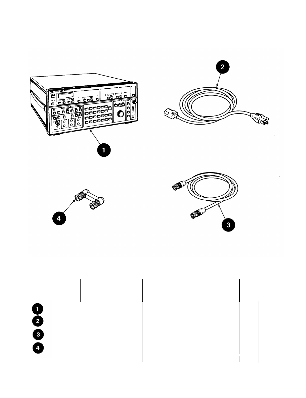
TM 11-6625-3087-12
Section Il. COMPONENTS OF END ITEM
C-2
(1)
Illus
Number
(2)
National Stock
Number
6150-00-041-5038 CABLE ASSEMBLY, POWER
5935-01-149-2471
Description
FSCM and Part Number
SELECTIVE LEVEL METER
(28480) 3586B/001/001/003/004/907
(70903) KH7147
CABLE ASSEMBLY, BNC
(28480) 8120-0688
ADAPTER, ELECTRICAL CONN
(94375) RF03152M
(3)
(4)
U/M
EA
EA
EA
EA
(5)
Qty
Rqr
1
1
1
1
Page 88

APPENDIX D
ADDITIONAL AUTHORIZATION LIST
TM 11-6625-3087-12
Section I.
D-1. SCOPE.
This appendix lists additional items you are
D-2. GENERAL.
This list identifies items that do not have to
items are all authorized to you by CTA, MTOE, TDA, or JTA.
D-3. EXPLANATION OF LISTING.
National stock numbers, descriptions, and quantities are provided to help you identify and request the additional items you
require to support this equipment. The items are listed in alphabetical sequence by item name under the type document (i.e.,
CTA,
MTOE,
TD, or JTA) which authorized
Section Il.
(1)
NATIONAL
STOCK
NUMBER
FSCM and PART NUMBER
authorized for the support of the AN/USM-490.
accompany the AN/USM-490 and that do not have to be turned in with it. These
the item(s) to you.
ADDITIONAL
INTRODUCTION
AUTHORIZATION LIST
(2)
DESCRIPTION
USABLE ON CODE
(3)
U/M
(4)
QTY
AUTH
5920-00-280-4960
FUSE, CARTRIDGE
(81349) F02A250B1A
FUSE, CARTRIDGE
(81 349) F02A250V2A
I
EA
EA
1
1
D-1/(D-2 Blank)
Page 89

Page 90

APPENDIX E
EXPENDABLE SUPPLIES AND MATERIALS LIST
TM 11-6625-3087-12
Section I.
E-1. SCOPE.
This appendix lists expendable supplies you will need for general support maintenance on frequency selective level meter
AN/USM-490. These items are authorized to you by CTA 50-970, Expendable items (Except Medical, Class V, Repair
Parts, and Heraldic Items).
E-2. EXPLANATION OF COLUMNS.
a Column (1)---Item Number. This number is assigned to the entry in the listing and is referenced in the narrative
instructions to identify the material (e.g.,
b. Column (2)----Level. This column identifies the lowest level of maintenance that requires the listed item.
0- Organizational Maintenance.
c. Column (3)--National Stock Number. This column indicates the national stock number assigned to the item and
will be used for requisitioning purposes.
d Column (4)--Description.
identify the item. The last line for each item indicates the FSCM (in parentheses) followed by the part number.
e.
Column (5)-Unit of Measure (U/M). This column indicates the measure used in performing the actual maintenance
function. This measure is expressed by a two-character alphabetical abbreviation (e.g., EA, IN, PR). If the unit of measure
differs from the unit of issue, requisition the lowest unit of issue that will satisfy your requirements.
Section Il. EXPENDABLE SUPPLIES AND MATERIALS LIST
“Use cleaning compound, item 5, App. D“).
This column indicates the federal item name and if required, a minimum description to
INTRODUCTION
(1)
ITEM
NUMBER
1
2
(2)
LEVEL
0
0
(3)
NATIONAL
STOCK
NUMBER
8305-00-267-3015
6810-00-753-4993
(4)
DESCRIPTION
Cloth, Cheesecloth, Cotton,
Lintless, CCC-C-440, Type II,
Class 2 (81349)
Alcohol, Isopropyl, 8oz Can,
MlL-A-10428, Grade A (81349)
(5)
U/M
YD
CN
E-1/(E-2 Blank)
Page 91

Page 92

INDEX
TM 11-6625-3087-12
Paragraph
Figure, Table,
Number
A
Abbreviations . . . . . . . . . . . . . . . . . . . . . . . . . . . . . . . . . . . . . . . . . . . . . . . . . . . .
Administrative Storage
Air Filter Replacement . . . . . . . . . . . . . . . . . . . . . . . . . . . . . . . . . . . . .
Bumper Replacement . . . . . . . . . . . . . . . . . . . . . . . . . . . . . . . . . . . .. . . . . . . . . .
Calibration/Tracking Section . . . . . . . . . . . . . . . . . . . . . . . . . . . . .
Capabilities and Features . . . . . . . . . . . . . . . . . . . . . . .
Characteristics, Performance . . . . . . . . . . . . . . . . . . . . . . . .
Characteristics . . . . . . . . . . . . . . . . . . . . . . . . . . . . . . . . . . . . .
Checking Unpacked Equipment . . . . . . . . . . . . . . . . . . . . . . . .
Cleaning . . . . . . . . . . . . . . . . . . . . . . . . . . . . . . . . . . . . . . . . . . . . . . . . . .
Common Names . . . . . . . . . . . . . . . . . . . . . . . . . . . . . . . . . . . . . . .
Common Tools and Equipment . . . . . . . . . . . . . . . . . . . . . . .
Components of End Item . . . . . . . . . . . . . . . . . . . . . . . . . . . . . .
Conditions, Operating
Unusual . . . . . . .. . . . . . . . . . . . . . . . . . . . . . . . . . . . . . . .
Usual . . . . . . . . . . . . . . . . . . . . . . . . . . . . . . . . . . . . . . . . . . . . . . . . . . . . . . . . . . . . .
Controls, Indicators, and Connectors . . . . . . . . . . . . . . . . . . . . . . . . . . . . . . .
Consolidated Index of Army Publications and Blank Forms . . . . . . . . . . . . .
Cross-Reference List . . . . . . . . . . . . . . . . . . . . . . . .. . . . . . . . . . . . . . . . . . . .
. . . . . . . . . . . . . . . . . . . . . . . . . . . . . . . . . . . . . . . . . . . . . . . . . . .. . . . . . . .
B
C
D
1-9
1-4
3-12
3-11,3-13
1-12, F1-2
1-10
1-11
1-10
3-4
2-3
1-8
Appendix B
Appendix C
2-20
2-9
2-1
1-2
1-8
Data, Equipment
Destruction of Army Materiel . . . . . . . . . . . . . . . . . . . . . . . . . . . . . . . .
Digital Section . . . . . . . . . . . . . . . . . . . . . . . . . . . . . . . . . . . . . . . . .
Dimensions . . . . . . . . . . . . . . . . . . . . . . . . . . . . . .
Environmental . . . . . . . . . . .. . . . . . . . . . . . . . . . . . . . . . . . . . . . . . . . . . . . . .
Equipment, Common Tools . . . . . . . . . .. . . . . . . . . . . . . . . . . . . . . .
Equipment Data . . . . . . . . . . . . . . . . . . . . . . . . . . . . . . . . . . . .
Equipment Improvement Recommendation . . . . . . . . . . . .
Equipment Purpose
Equipment, Special Tools, TMDE, and Support . . . . . . . . . . . .
Error Messages . . . . . . . . . . . . . . . . . . . . . . . . . . . . . . . .
. . . . . . . . . . . . . . . . . . . . . . . . . . . . . . . . . .
E
. . . . . . . . . . . . . . . . . . . . . . . . . . . . . . . . . . . . . . . . . . . . .
1-11
1-5
1-12,F1-2
1-11
1-11,3-19
3-1
1-11
1-6
1-1
3-2
2-8,T2-2
INDEX-1
Page 93

TM 11-6625-3087-12
F
Features . . . . . . . . . . . . . . . . . . . . . . . . . . . . . . . . . . . .
First Local Oscillator Section . . . . . . . . . . . . . . . . . . . . . . . .
Frequency Reference Section
Front Handle Replacement . . . . . . . . . . . . . . . . . . . . . . . . . . .
Functional Description . . . . . . . . . .. . . . . . . . . . . . . . . . . . .
Fuse Replacement
lF/Audio Section
Impairments Section . . . . . . . .. . . . . . . . . . . . .
Indicators . . . . . . . . . . . . . . . . . . . . . . . . . . . . . . . . . . . . . . . . . . . . . . . . . . . . . . . . . . . . . . . . .
Input Power Requirements . . . . . . . . . . . . . .
Input Sect ion
Inspections . . . . . . . . . . . . . . . . . . . . . . . .
Interface Section
Knob Replacement . . . . . . . . . . . . . . . . . . . .
Level Meter, AN/USM-490 . . . . . . .
List of Abbreviations . . . . . . . . . . . . . . . . . . . .
List of Capabilities
List of Characteristics . . . . . . . . . . . . . . . . .
List of Common Names . . . . . . . . . . . . . .
List of Control initial Setup positions . . . . . . . . . .
List of Equipment Data
List of Expendable Supplies and Materials . .. . . . . . . . . . . . . .
List of Operator Troubleshooting . . . . . . . . . . . . . . . . . . . . . . . . . .
List of PMCS Procedures . . . . . . . . . . . . . . . . . . . . . . . . . . . .
List of References
List of Voltage Selection Switch Positions and Fuses . . . .. . . . . . . . . . . . . . . . . . . . . . . . . . . . . . .
. . . . . . . . . . . . . . . . . . . . . . . . . . . . . . . . . . . . . . . . . . . . . . . . . . .
. . . . . . . . . . . . . . . . . . . . . . . . . . . . . . . . . . . . . . . . . . . . . . . . . . . . . . .
. . . . . . . . . . . . . . . . . . . . . . . . . . . . . . . . . . . . . . . . . . . . . . . . . . . . . . . .
. . . . . . . . . . . . . . . . .
. . . . . . . . . . . . . . . . . . . . . . . . . . .
. . . . . . . . . . . . . . . . . . . . . . . . . . . . . . .
. . . . . . . . . . . . . . . . . . .. . . . . . . . . . . . . . . . . .
. . . . . . . . . . . . . . . . . . . . . . . . . . . . . . . . . . . . . . . . . . . . .
I
K
L
Appendix E
Appendix A
1-10
1-12, F1-2
1-12, F1-2
3-15
1-12
1-12, F1-2
1-12, F1-2
1-12,F1-2
1-12, F1-2
1-8,F1-1
3-6,T3-1
2-5,T2-1
3-8
2-1
1-11
2-3
3-9
1-9
1-10
1-10
1-8
2-6
1-11
2-3
M
Maintenance Allocation Chart (MAC)
Maintenance Forms and Records, and Reports . . . . . . . . . . . . . . . . . .
Maintenance, Operator Preventive
Maintenance Procedures . . . . . . . . . . . . .
Nomenclature Cross-Reference List . . . . . . . . . .
INDEX-2
. . . . . . . . . . . . . . . . . . . . . . . .
. . . . . . . . . . . . . . . . . .
N
Appendix B
1-3
2-3
3-7
1-8
Page 94

O
Operational Modes
2600Hz . . . . . . . . . . . . . . . . . . . . . . . . . . . . . . . . . . .
Carrier . . . . . . . . . . . . . . . . . . . . . . . . . . . . . . . . . . . . . . . . . . . . . . . . . .
Impulse . . . . . . . . . . . . . . . . . . . . . . . . . . . . . . . . . .
LO Noise . . . . . . . . . . . . . . . . . . . . . . . . . . . . . . . . . . . . . . . .
Network Analysis . . . . .. . . . . . . . . . . . . . . . . . . . . . . . . . .
Noise/Demodulation . . . . . . . . . . . . . . . . . .
Noise/Tone . . . . . . . . . . . . . . . . . . . . . . . . . . . . . . . . . . .
Phase Jitter . . . . . . . . . . . . . . . . . . . . . . . . . . . . . . . . . . . . .
Tone 1004Hz . . . . . . . . . . .. . . . . . . . . . . . . . . . . . . .
Wideband . . . . . . . . . . . . . . . . . . . . . . . . . . . . . . . . . . . .
Operating Principles
Operating Procedure . . . . . . . . . . . . . . . . . . . . . . . . . . . . . . . . .
Operation Requirements . . . . . . . . . .. . . . . . . . . . . . . . . . . . . . . . . . . . . . . . .
Operational Test
Operator’s Controls, Indicators, and Connectors . . . . . . . . . . . . . . .
. . . . . . . . .. . . . . . . . . . . . . . . . . . . .
. . . . . . . . . . . . . . . . . . . . . . . . . . . . . . . .
P
TM 11-6625-3087-12
2-15,T2-3
2-17,T2-3
2-18,T2-3
2-11,T2-3
2-19,T2-3
2-13,T2-3
2-16,T2-3
2-14,T2-3
2-15,T2-3
2-12,T2-3
1-12
2-1
1-11
3-7
2-1
Packing
Parts, Repair
Performance Characteristics
Power Requirement
Power Supply Section . . . . . . . . . . . . . . . . . . . . . . . . . . . .
Preparation for Storage and Shipment . . . . . . . . . . . . . . . . . . . . . . . . . .
Preparation for Use . . . . . . . .. . . . . . . . . . . . . . . . . . . . . . . . . . . . . . . . . . . .
Preventive Maintenance . . . . . . . . . . . . . . . . . . . . . . . . . . . . . . . . . .
Principles of Operation . . . . . . . . . . .. . . . . . . . . . . . . . . . . . . . . . .
Procedures, Operating . . . . . . . . . . . . . . . . . . . . . . . . . . . . . .
Procedures, Store/Recall . . . . . . .. . . . . . . . . . . . . . . . . . . . . . .
Procedures, Turn-On . . . . . . . . . . . .. . . . . . . . . . . . . . . . . . . . . . . .
Push Button Replacement . . . . . . . . . . . . . . . . . . . . . .
Records, Maintenance . . . . . . . . . . . . . . . . . . . . . . . . . . . . . . . . . . . .
References . . . . . . . . . . . . . . . . . . . . . . . . . . . . . . . . . . . . .
Repair Parts . . . . . . . . . . . . . . . . . . . . . .. . . . . . . . . . . . . . . . . . . .
Replacement, Air Filter
Replacement, Bumper . . . . . . . . . .. . . . . . . . . . . . . . . . . . .
Replacement, Fuse . . . . . . . . . . . . . . . . . . . . . . . .
Replacement, Knob . . . . . . . . . . . . . . . . . . . . . .
Replacement, Push Button
Replacement, Front Handle . . . . . . . . . .
Replacement, Side Handle . . . . . . .. . . . . . . . . . . .
Reports, Maintenance . . . . . . . . . . . . . . . . . . . . . . . .
. . . . . . . . . . . . . . . . . . . . . . . . . . . . . . . . . . . . . . . . . . . . . . . . . . . . . . . . . . . . . . . . . . . . . . . . . . . . . . . . . . . . . . . . . . . . . . . . . . . . . . . . . . .
. . . . . . . . . . . . . . . . . . . . . . . . . . . . . . . . . . . . . . . . . . . . . . . . . . . . . . . . . . . . . . . . . . . . . . . . . . . . . . . . . . . . . . . . . . . . . . . . . . . .
. . . . . . . . . . . . . . . . . . . . . . . . . . . . . . . . . . . . . . . . . . . . . . . . . . . . . . . . . . . . . . . . . . . . . . . . . . . . .
. . . . . . . . . . . . . . . . . . . . . . . . . . . . . . . . . . . . . . . . . . . . . . . . . . . . . . . . . . . . . . . . . . . . . . . . . . . . . . . . . . . . . . . . .
R
. . . . . . . . . . . . . . . . . . . . . . . . . . . .
. . . . . . . . . . . . . . . . . . . . . . . . . . . . . . . .
3-16
3-3
1-11
1-11
1-12,F1-2
3-16
2-5
2-3
1-12
2-9
2-7
2-6
3-10
1-3
Appendix A
3-3
3-12
3-11,3-13
3-8
3-9
3-10
3-15
3-14
1-3
S
Service Upon Receipt . . . . . . . . . . . . . . . . . . . . . . . . . . . . . . .
Setup, Control Initial . . . . . . . . . . . . . . . . . . . . . . . . . . . . . . . . . . . . .
Shipment . . . . . . . . . . . . . . . . . . . . . . . . . . . . . . . . . . . . . .
Side Handle Replacement
Special Tools and Test Equipment . . . . .. . . . . . . . . . .
Storage . . . . . . . . . . . . . . . . . . . . . . . . . . .
. .. . .
3-4
2-6
3-16
3-14
3-2
3-17
INDEX-3
Page 95

TM 11-6625-3087-12
T
Test Equipment . . . . . . . . . . . . . . . . . . . . . . . . . . . . . . . . .
Tools, Common
Tools, Special
Troubleshooting
Unpacking . . . . . . . . . . . . . . . . . . . . . . . . . . . . . . . . . . . . .
Unusual Conditions
Warranty . . . . . . .. . . . . . . . . . . . . . . . . . . . . . . . . . . . . .
Weight . . . . . . . . . . . . . . . . . . .
. . . . . . . . . . . . . . . . . . . . . . . . . . . .. . . . . . . . . . . . . . . . . . . . . . . . . . . . . . . .
. . . . . . . . . . . . . . . . . . . . . . . . . . . . . . . . . . . . . . . . . . . . . . . . . . . . . . . . . . . .
. . . . . . . . . . . . . . . . . . . . . . . . . . . . . . . . . . . . . . . . . . . . . . . . . . .
U
. . . . . . . . . . . . . . . . . . . . . . . . . . . . . . . . . . . . . . . . .
W
Appendix B
3-1
3-2
3-6,T3-1
3-4
2-20
1-7
1-11
INDEX-4
Page 96

By Order of the Secretary of the Army:
Official:
R.L. DILWORTH
Brigadier General, United States Army
The Adjutant General
DISTRIBUTION:
To be districted in accordance with DA Form 12-51 literature
requirements for AN/USM490.
JOHN A, WICKHAM, JR.
General, United States Army
Chief of Staff
Page 97

Page 98

These are the instructions for sending an electronic 2028
The following formatmust be used if submittingan electronic 2028. The subjectline must be
exactly the same and all fields must be included; however only the following fields are
mandatory: 1, 3, 4, 5, 6, 7, 8, 9, 10, 13, 15, 16, 17, and 27.
Subject: DA Form 2028
1. From: Joe Smith
2. Unit: home
3. Address: 4300 Park
4. City: Hometown
5. St: MO
6. Zip: 77777
7. Date Sent: 19--OCT--93
8. Pub no: 55--2840--229--23
9. Pub Title: TM
10. Publication Date: 04--JUL--85
11. Change Number: 7
12. Submitter Rank: MSG
13. Submitter FName: Joe
14. Submitter MName: T
15. Submitter LName: Smith
16. Submitter Phone: 123--123--1234
17. Problem: 1
18. Page: 2
19. Paragraph: 3
20. Line: 4
21. NSN: 5
22. Reference: 6
23. Figure: 7
24. Table: 8
25. Item: 9
26. Total: 123
27. Text:
This is the text for the problem below line 27.
Page 99

Page 100
RECOMMENDED CHANGES TO PUBLICATIONS AND
BLANK FORMS
For use of this form, see AR 25--30; the proponent agency is O DISC4.
UsePartII(reverse) for Repair Parts and Spe-
cial Tool Lists (RPSTL) and Supply Catalogs/
Supply Manuals (SC/SM)
DATE
8/30/02
TO: (Forward to proponent of publication or form)(Include ZIP Code)
Commander, U.S. Army Aviation and Missile Command
ATTN: AMSAM--MMC--MA--NP
R eds t one A r s enal, AL 35898
PART1 -- ALL PUBLICATIONS (EXCEPT RPSTL AND SC/SM) AND BLANK FORMS
PUBLICATION/FORM NUMBER
TM 9--1005--433--24
ITEM
NO.
PAGE
NO.
1 WP0005
PG 3
PARA--
GRAPH
LINE
NO. *
2 Test or Corrective Action column should identify a different WP number.
FIGURE
NO.
TABLE
NO.
FROM: (Activity and location)(Include ZIP Code)
MSG, Jane Q. Doe
1234 Any Street
Nowhere Town, AL 34565
DATE
16 Sep 2002
TITLE Organizational, Direct Support, And General
Support Maintenance Manual for Machine Gun, .50
Caliber M3P and M3P Machine Gun Electrical Test Set
Used On Avenger Air Defense Weapon System
RECOMMENDED CHANGES AND REASON
* Reference to line numbers within the paragraph or subparagraph.
TYPED NAME, GRADE OR TITLE
MSG, Jane Q. Doe, SFC
DA FORM 2028, FEB 74 REPLACES DA FORM 2028, 1 DEC 68, WHICH WILL BE USED. USAPA V3.01
TELEPHONE EXCHANGE/
AUTOVON, PLUS EXTENSION
788--1234
SIGNATURE
 Loading...