

Page 1

Page 2

Page 3

Note: Unless ot h erwise ind i cated, this manual applies t o all Serial Nu m b e rs.
The Agilent Technologies 34401A is a 6
1
⁄
-digit, high-performance
2
digital multimeter. Its co m bination o f b e nch- to p and system f e atur e s
makes this multimeter a versatile solution for y our m easurement n eeds
now and in the future.
Convenient Bench-Top Features
• Highly visible vacuum-fluorescent displ a y
• Built-in math operations
• Continuity and diode test functions
• Hands-free, Reading Hold feature
• Portable, ruggedized case with non-skid feet
Flexible System Features
• GPIB (IEEE-488) interface and RS-232 interface
• Standard programming languages: SCPI, Agilent 3478A, and
Fluke 8840
• Reading rates up to 1000 readings per second
• Storage for up to 512 readings
• Limit testing with pass/fail signals
• Optional 34812A BenchLink/Meter Software for Microsoft
Windows
TM
Agilent 34401A
Multimeter
®
Page 4

The Front Panel at a Glance
1 Measurement Function keys
2 Math Operation keys
3 Single Trigger / Autotrigger / Reading Hold key
4 Shift / Local key
2
5 Front / Rear Input Terminal Switch
6 Range / Number of Digits Displayed keys
7 Menu Operation keys
Page 5

The Front-Panel Menu at a Glance
The menu is organized in a top-down tree structure with three levels.
A: MEASurement MENU
1: AC FILTER > 2: CONTINUITY > 3: INPUT R > 4: RATIO FUNC > 5: RESOLUTION
B: MATH MENU
1: MIN-MAX > 2: NULL VALUE > 3: dB REL > 4: dBm REF R > 5: LIMIT TEST > 6: HIGH LIMIT > 7: LOW LIMIT
C: TRIGger ME N U
1: READ HOLD > 2: TRIG DELAY > 3: N SAMPLES
D: SYStem MENU
1: RDGS STORE > 2: SAVED RDGS > 3: ERROR > 4: TEST > 5: DISPLAY > 6: BEEP > 7: COMMA > 8: REVISION
E: Input / Output MENU
1: HP-IB ADDR > 2: INTERFACE > 3: BAUD RATE > 4: PARITY > 5: LANGUAGE
F: CALibration MENU
1: SECURED > [ 1: UNSECURED ] > [ 2: CALIBRATE ] > 3: CAL COUNT > 4: MESSAGE
The commands enclosed in square brackets ( [ ] ) are “hidden” unless the multimeter
*
is UNSECURED for calibration.
*
3
Page 6

Display Annunciators
∗
Adrs
Rmt
Man
Trig
Hold
Mem
Ratio
Math
ERROR
Rear
Shift
4W
Turns on during a measurement.
Multimeter is addressed to listen or talk over the GPIB interface.
Multimeter is in remote mode (remote interface).
Multimeter is using manual ranging (autorange is disabled).
Multimeter is waiting for a single trigger or external trigger.
Reading Hold is enabled.
Turns on when reading memo ry is enabled.
Multimeter is in dcv:dcv ratio function.
A math operation is enabled (null, min-max, dB, dBm, or limit test).
Hardware or remote interface command errors are detected.
Rear input terminals are selected.
“Shift” key has been pressed.
Multimeter is in 4-wire ohms function.
Multimeter is in continuity test function.
Multimeter is in diode test function.
Press “Shift” again to turn off.
To review the display annunciators, hold down the Shift key as you
turn on the multimeter.
4
Page 7

The Rear Panel at a Glance
1 Chassis Ground
2 Power-Line Fuse-Holder Assembly
3 Power-Line Voltage Setting
4 Front and Rear Current Inpu t Fuse
5 Voltmeter Complete Output Terminal
6 External Trigger Input Terminal
7 GPIB (IEEE-488) Interface connector
8 RS-232 interface connector
Use the front-panel Input / Output Menu to:
• Select the GPIB or RS-232 interface (see chapter 4).
• Set the GPIB bus address (see chapter 4).
• Set the RS-232 baud rate and parity (see chapter 4).
5
Page 8

In This Book
Quick Start Chapter 1 prepares the multimeter for use and helps you
get familiar with a few of its front-panel features.
Front-Panel Menu Operation Chapter 2 introduces you to the
front-panel menu and describes some of t he mu ltimeter’s menu fea tur es.
Features and Functions Chapter 3 gives a detailed description of the
multimeter’s capabilities and operation. You will find this chapter
useful whether you are operating the multimeter from the front panel or
over the remote in t er fac e.
Remote Interface Reference Chapter 4 contains reference
information to help you program th e m ultimeter over t he rem ote interface.
Error Messages Chapter 5 lists the error messages that may appear
as you are working with the multimeter. Each listing contains enough
information to help you diagnose and solve the problem.
Application Programs Chapter 6 contains several remote interface
application programs to help you develop programs for your
measurement application.
Measurement Tutorial Chapt er 7 discusses measure m e nt
considera ti ons an d te chn iq u es to hel p you obt ai n the bes t acc u rac ies
and reduce sources of measurement error.
Specifications Chapter 8 lists the multimeter’s specifications and
describes how to interpret these specifications.
If you have questions relating to the operation of the Agilent 34401A,
call 1-800-452-4844 in the United States, or contact your nearest
Agilent Sal es Of fic e .
If your 34401A fails within three years of purchase, Agilent will repair
or replace i t free of c harge. Call 1-877-444-7278 (“Agilent Express”) in
the United State s, or con tact your n ear est A gile nt Sales Office.
6
Page 9

Contents
Chapter 1 Quick Start
To Prepare th e Multimeter for Us e 13
If the Multi meter Does Not T urn On 14
To Adjust the Carrying Handle 16
To Measure Volt ag e 17
To Measure Resis tan ce 17
To Measur e C urr en t 18
To Measure Frequency (or Period) 18
To Test Continuity 19
To Check Di ode s 19
To Select a Range 20
To Set th e R e s olu t io n 21
Front-Panel Display Formats 22
To Rack Mount th e Multimeter 23
Chapter 2 Front-Panel Menu Operation
Front-Panel Menu Reference 27
A Front-Panel Menu Tutorial 29
To Turn Off the Comma Separator 37
To Make Null (Relative) Measur em en t s 38
To Store Mi nim u m an d Max i mum Reading s 39
To Make dB M eas urements 40
To Make dBm Measurements 41
To Trigger the Multimeter 42
To Use Reading Hold 43
To Make dcv:dcv Ratio Measurements 44
To Use Reading Memory 46
Chapter 3 Features and Functions
Measurement Configuration
AC Signal Filter 51
Continuity Threshold Resistance 52
DC Input Resistance 53
Resolution 54
Integration Time 57
Front / Rear Input Terminal Switching 58
Autozero 59
Ranging 60
Contents
7
Page 10

Contents
Contents
Chapter 3 Features and Functions (continued)
Math Operations
Min-Max Operation 64
Null (Relative) Operation 65
dB Measurements 67
dBm Measurements 68
Limit Testing 69
Triggering
Trigger Source Choices 73
The Wait-for-Trigger State 76
Halting a Measurement in Progress 76
Number of S amples 77
Number of Tr ig g er s 78
Trigger Delay 79
Automatic Trigger Delays 81
Reading Hold 82
Voltmeter Complete Terminal 83
External Trigger Terminal 83
System-Related Operations
Reading Memory 84
Error Conditions 85
Self-Test 86
Display Control 87
Beeper Control 88
Comma Separators 89
Firmware Revision Query 89
SCPI Language Version Query 90
Remote Interface Conf iguration
GPIB Address 91
Remo te I n terface Selection 92
Baud Rate Se lection (RS-232) 93
Parity Selection (RS-232) 93
Programming Language Selection 94
Calibration
Calibration Security 95
Calibration Count 98
Calibration Message 99
Operator Maintenance
To Replace the Power-Line Fuse 100
To Replace the Current Input Fu s es 100
Power-On and Reset State 101
8
Page 11

Contents
Chapter 4 Remote I nterface Reference
Command Su mmary 105
Simplified P rog r amming Overview 112
The MEASure? and CONFigure Commands 117
Measurement Configuration Commands 121
Math Operation Commands 124
Triggering 127
Triggering Commands 130
System-Rel ate d Commands 132
The SCPI Status Model 134
Status Reporting Commands 144
Calibration C om ma n ds 146
RS-232 Interface Configuration 148
RS-232 Interface Commands 153
An Introd uct ion to the SCPI L an gu age 154
Output Data Formats 159
Using Device Clear to Halt Measurements 160
TALK ONLY for Printers 160
To Set the GPIB Address 161
To Select the R em ote Interface 162
To Set th e B au d Rate 163
To Set th e P arity 164
To Select the Programming Language 165
Alternate Programming Language Compatibility 166
SCPI Complianc e I nfo rmation 168
IEEE-488 Compliance Information 169
Contents
Chapter 5 Error Messages
Execution Errors 173
Self-Test E r rors 179
Calibration E rr ors 180
Chapter 6 Application Programs
Using MEASure? for a Single Measur ement 185
Using CONFigure with a Math Operation 186
Using the Status Registers 188
RS-232 Operation Using QuickBASIC 192
RS-232 Operation Using Turbo C 193
9
Page 12

Contents
Contents
Chapte r 7 Measurement Tutorial
Thermal EMF Errors 199
Loading Errors (dc volts) 199
Leakage Current Errors 199
Rejecting Power-Line Noise Voltages 200
Common Mode Rejection (CMR) 201
Noise Caused by Magnetic Loops 201
Noise Caused by Ground Loops 202
Resistan ce Measurem ents 203
4-Wire Ohms Meas ur em ent s 203
Removing Test Lead Resistance Errors 204
Power Dissipat ion Effects 204
Settling T im e E f fec ts 204
Errors in High Resistance Mea surements 20 5
DC Current Measurement Errors 205
True RMS AC Measurements 206
Crest Fa ct or Errors 207
Loadi ng Errors (a c v olts) 209
Measurem ents Below Full S cal e 210
High-Voltage Self-Heating Errors 210
Temperature Coefficien t and O v erload Errors 210
Low-Level Measurement Errors 211
Common Mode Errors 212
AC Current Measurement Errors 212
Frequency and Peri od M easurement Errors 213
Making H ig h- Speed DC and Res is tance Measurements 213
Making High - Sp eed AC Measurement s 214
Chapter 8 Specifications
DC Character is tic s 216
AC Character is tic s 218
Frequency and Peri od Ch a rac teristics 220
General Information 222
Product Dimensions 223
To Calcula te Tot a l M eas urement Err or 224
Interpreting Multimeter Specifications 226
Configur in g f or H ig h est Accura cy Measurem ents 229
Index 231
Declaration of Conformity 237
10
Page 13

1
1
Quick Start
Page 14

Quick Start
One of the first things you will want to do with your multimeter is to
become acquainted with its front panel. We have written the exercises
in this chapter to prepare the multimeter for use and help you get
familiar with some of its front-panel operations.
The front panel has two rows of keys to select various functions and
operations. Most ke ys have a shifted function printed in bl ue above
the key. To perform a shifted function, press
annunciator will turn on). Then, press the key that has the desired
label above it. For example, to select the dc current function,
Shift DC V .
press
Shift (the Shift
If you accident a l ly press
Shift annunciato r.
The rear cover of this bo ok is a fold -out Qu ick Re feren ce Gu ide. On t his
cover you will find a quick summary of va rious multimeter features.
Shift , just press it again to turn off the
12
Page 15

Chapter 1 Quick Start
To Prepare the Multimeter for Use
To Prepare the Multimeter for Use
The following steps help you verify that the multimeter is ready for use.
1 Check the list of suppl ied items.
Verify that you have received the following items with your multimeter.
If anyt hi ng i s mi s si ng , c o nt a ct y o ur nearest A g ile n t Sales Offi ce.
One test lead kit.
One power cord.
This User’s Guide.
One Service Guide.
One folded Quick Reference card.
Certificate of Calibration.
2 Connect the power cord and turn on the multimeter.
1
The front-panel display will light up while the multimeter performs its
power-on self-test. The
multimeter powers up in the dc voltage function with autorang ing enab led.
To review the power-on display with all annunciators turned on,
hold down
3Perform a complete self-test.
The complete self-test perfor ms a more ex ten siv e ser i es of tests tha n
those performed at power-on. Hold down
Power switch to turn on the multimeter; hold down the key for more
than 5 seconds. The self-test will begin when you release the key.
If the self-test is successful, “
not successful, “
See the Service Guide for instructions on returning the multimeter to
Agilent for service.
Shift as you tur n on th e mu lti met e r.
FAIL” is displayed and the ERROR annunciator turns on.
GPIB bus address is displayed. Notice that the
Shift as you pres s the
PASS” is displayed. If the self-test is
13
Page 16
Chapter 1 Quick Start
If the Multimeter Does Not Turn On
If the Multimeter Does Not Turn On
Use the following steps to help solve problems you might encounter
when turning on the multimeter. If you need more help, see the
Service Gui de for instructions on returning the multimeter to Agilent for
service.
1 Verify that there is ac power to the multi meter.
First, verify that the multimeter’s Power switch is in the “On” position.
Also, make sure that the power cord is firmly plugged into the power
module on the rear panel. You should also make sure that the power
source you plugged the multimeter into is energized.
2 Verify the power-line voltage setting.
The line voltage i s set to the pr oper valu e for yo ur co un tr y when the
multimeter is shipped from the factor y . Chang e t he voltag e se tt ing i f
it is not correct. The settings are: 100, 120, 220, or 240 Vac (for 230 Vac
operation, use the 220 Vac setting).
1
See the next page if you need to change the li ne-voltage setting.
3 Verify that the power-line fuse is good.
The multimeter is shipped from the factory with a 250 mA fuse
installed. This is the correct fuse for all line voltages.
See the next page if you need to replace the power-line fuse.
To replace the 250 mAT fuse, order Agilent part number 2110-0817.
14
Page 17

Chapter 1 Quick Start
If the Multimeter Does Not Turn On
1
1 Remov e th e powe r co rd. Remove the
fuse-holder assembly from the rea r pan el.
3 Rotate the line-voltage selector until the
correct voltage appears in the window.
2 Remove the line-voltage selector from
the assembly.
See rear panel for proper fuse rating.
Agilent Part Number: 2110-0817 (250 mAT)
2110-0894 (125 mAT)
4 Replace the fuse-h ol der assemb ly in
the rear panel.
100, 120, 220 (230) or 240 Vac
Verify that the correct line voltage is selected and the power-line fuse is good.
15
Page 18

Chapter 1 Quick Start
To Adjust the Carrying Handle
To Adjust the Carrying Handle
To adjust the position, grasp the handle by the sides and pull outwar d.
Then, rotate the handle to the desired position.
Bench-top viewing positions Carrying position
16
Page 19

Chapter 1 Quick Start
To Measure Voltage
To Measure Voltage
Ranges: 100 mV, 1 V, 10 V, 100 V, 1000 V (750 Vac)
Maximum resolution: 100 nV (on 100 mV range)
AC technique: true
RMS, ac-coupled
1
To Measure Resistance
Ranges: 100 Ω, 1 kΩ, 10 kΩ, 100 kΩ, 1 MΩ, 10 MΩ, 100 MΩ
Maximum resolution: 100 µΩ (on 100 ohm range)
17
Page 20

Chapter 1 Quick Start
To Measure Current
To Measure Current
Ranges: 10 mA (dc only), 100 mA (dc only), 1 A , 3 A
Maximum resolution: 10 nA (on 10 mA range)
AC technique: true
RMS, ac-coupled
To Measure Frequency (or Period)
Measurement band: 3 Hz to 300 kHz (0.33 sec to 3.3 µsec)
Input signal range: 100 mVac to 750 Vac
Techniqu e: reciprocal count i ng
18
Page 21

Chapter 1 Quick Start
To Test Continuity
To Test Continuity
Test current source: 1 mA
Maximum resolution: 0.1
Beeper threshold: 1
Ω (range i s fi xed at 1 ko hm )
Ω to 1000 Ω (beeps below adjustable threshold)
1
To Check Diodes
Test current source: 1 mA
Maximum resolution: 100
Beeper threshold: 0.3 volts
µV (range i s fi xed at 1 Vd c)
≤ V
measured
≤ 0.8 volts (no t adjustable)
19
Page 22

Chapter 1 Quick Start
To Select a Range
To Select a Range
You can let the multimeter automatically select the range using
autoranging or you can select a fi xed range using manual ra nging.
Selects a lower range and
disables autoranging.
Selects a higher range and
disables autoranging.
Toggles betwee n aut or anging
and manual ranging.
• Autoranging is sel e ct ed a t p ower-on a nd a ft e r a re m ot e i nt erf a ce reset.
• Autorange t h re sholds:
Man annu nci ator is on when
manual range is enabl ed.
Down range at <10% of range
Up range at >120% of range
• If the input signal is greater than the present range can measure,
the multimeter will give an overload indication (“
• For frequency and period measurements from the front panel,
OVLD”).
ranging applies to the signal’s input voltage, not its frequency.
• The range is fixed for conti n u ity (1 kΩ range) and diode (1 Vdc ran g e).
Ranging is local to the selected function. This means that you can select
the ranging method (auto or manual) for each function independently.
When manually ranging, the selected range is local t o th e fu nction ;
the multimeter remembers the range when you switch between functions.
20
Page 23

Chapter 1 Quick Start
To Set the Resolution
1
To Set the Resolution
You can set the display resolution to 4
1
1
⁄
, 5
2
⁄
, or 6
2
1
⁄
digits either to
2
optimize measur emen t speed or nois e reje ction. In this book, the most
1
⁄
significant digit (leftmost on the display) is referred to as the “
” digit,
2
since it can only be a “0” or “1.”
Press the Shift key.
1
Selects 4
⁄2 digits.
Selects 5
1
⁄2 digits.
Sele cts 61⁄2 digits (most noise reject i on ).
• The resolution is set to 5
1
⁄
digits at power-on and after a remote
2
interface reset.
• The resolution is fixed at 5
• You can also vary the number of digits displayed using the arrow keys
1
⁄
digits for continuity and diode tests.
2
(however, the integration time is not changed).
Fewer More
Digits Digits
Resolutio n is local to t he selected func tion. This means t hat you can
select the r esolutio n for each fun ction inde pendently. T he multime ter
remembers the resolution when you switch between functions.
21
Page 24

5 digits
Chapter 1 Quick Start
Front-Panel Display Formats
Front-Pan el Display Formats
– Negative sign or blank (positive)
1
H “
-H.DDD,DDD EFFF
Front-pa ne l display forma t.
10.216,5 VDC
D Numeric digits
E Exponent ( m, k, M )
F Measurement units ( VDC, OHM, HZ, dB )
⁄2 ” digit (0 or 1)
“1⁄2” digit
“1⁄2” digit
This is the 10 Vdc range, 5
1
⁄
digits are displayed.
2
-045.23 mVDC
This is the 100 mVdc range, 4
1
⁄
digits are displayed.
2
113.325,6 OHM
This is the 100 ohm range, 6
1
⁄
digits are displayed.
2
OVL.D mVDC
This is an overload indication on the 100 mVdc range.
22
Page 25

Chapter 1 Quick Start
To Rack Mount the Multimeter
To Rack Mount the Multimeter
You can mount the multi m eter in a standard 19 -inch rack cabinet using
one of three optional kits available. In struc tions and m ountin g hardw are
are included with each r ack-mou nting kit . Any
instrument of the same size can be rack-mounted beside the 34401A.
Remove the carrying handle, and the front and rear rubber bumpers,
before rack- m ounting the multim eter.
Agilent System II
1
To remove the handle, rotate it to the vertical position and pull the ends outward.
Fron t
To remove the rubber bumper, stretch a corner and then slide it off.
Rear (bottom view)
23
Page 26
Chapter 1 Quick Start
To Rack Mount the Multimeter
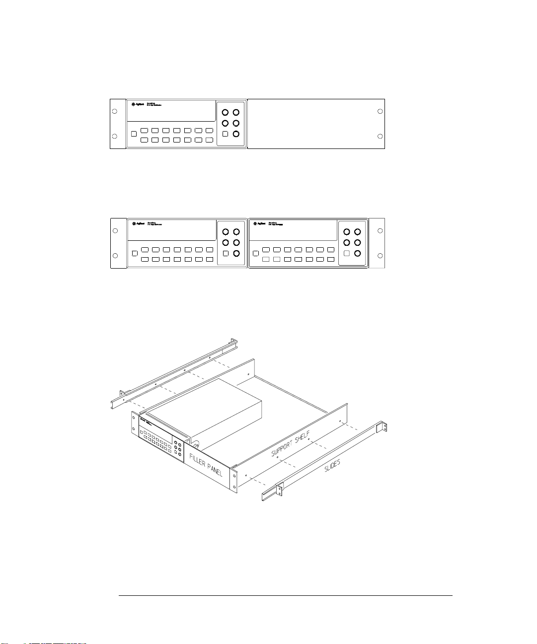
To rack mount a single instrument, order adapter kit 5063-9240.
To rack mount two instruments side-by-side, order lock-link kit 5061-9694 and
flange kit 5063-9212.
To install one or two instruments in a sliding support shelf, order shelf 5063-9255,
and slide kit 1494-0015 (for a single instrument, also order filler panel 5002-3999).
24
Page 27

2
2
Front-Panel
Menu Operation
Page 28

Front-Panel Menu Operation
By now you should be familiar with the FUNCTION and RANGE / DIGITS
groups of fro nt -panel keys. You should also understand how to make
front-panel connections for the various types of measurements. If you
are not familiar with this information, we recommend that you read
chapter 1, “Quick Start,” starting on page 11.
This chapter introduces you to three new groups of front-panel keys:
MENU, MATH, and TRIG. You will also learn how to use the comma
separator and store readings in memory. This chapter does not give a
detailed description of every front-panel ke y or menu operation. It does,
however, give you a good ov er vie w of th e fro nt- pan el menu a nd many
front-panel operations. See chap t er 3 “ F eat u re s and Fun c tion s ,” starting
on page 49, for a complete discussion of the multimeter’s capabilities
and operation.
26
Page 29

Chapter 2 Front-Panel Menu Operation
Front-Panel Menu Reference
Front-Panel Menu Reference
A: MEASurement MENU
1: AC FILTER > 2: CONTINUITY > 3: INPUT R > 4: RATIO FUNC > 5: RESOLUTION
1: AC FILTER
2: CONTINUITY
3: INPUT R
4: RATIO FUNC
5: RESOLUTION
Selects the slow, medium, or fast ac filter.
Sets the continuity beeper threshold (1 Ω to 1000 Ω).
Sets the input r esistance for dc voltage measurements.
Enables the dcv:dcv ratio function.
Selects the measuremen t resolution.
B: MATH MENU
1: MIN-MAX > 2: NULL VALUE > 3: dB REL > 4: dBm RE F R > 5: LIMIT TES T > 6: HIGH LIMI T > 7: LOW LIMIT
1: MIN- MAX
2: NULL VALUE
3: dB REL
4: dBm REF R
5: LIMIT TEST
6: HIGH LIMIT
7: LOW LIMIT
Recalls the stored minimum, maximum, average, and reading count.
Recalls or sets the null value stored in the null re gister.
Recalls or sets the dBm value stor ed in the d B relati ve register.
Selects the dBm reference resistance value.
Enables or disables limit testing.
Sets the upper limit for limit testing.
Sets the low er limit for limit testing.
C: TRIGger MENU
1: READ HOLD > 2: TRIG DELAY > 3: N SAMPLES
2
1: READ HOLD
2: TRIG DELAY
3: N SAMPLES
Sets the readin g ho ld se ns itiv ity ban d.
Specifies a time inte rval which is inserted before a mea s uremen t.
Sets the nu mb er of sa mp le s p er tr ig ge r .
27
Page 30

Chapter 2 Front-Panel Menu Operation
Front-Panel Menu Reference
D: SYStem MENU
1: RDGS STORE > 2: SAVED RDGS > 3: ERROR > 4: TEST > 5: DISPLAY > 6: BEEP > 7: COMMA > 8: REVISION
1: RDGS STORE
2: SAVED RDGS
3: ERROR
4: TEST
5: DISPLAY
6: BEEP
7: COMMA
8: REVISION
Enables or disables reading memory.
Recalls readings sto red in memory (up to 512 readings).
Retrieves errors from the error queue (up to 20 errors).
Performs a complete self-test.
Enables or disables th e front-panel display.
Enables or disables the beeper function.
Enables or disables a co mma separator between digi ts on the display.
Displays the multimeter’s fir mware revision codes.
E: Input / Output MENU
1: HP-IB ADDR > 2: INTERFACE > 3: BAUD RATE > 4: PARITY > 5: LANGUAGE
1: HP-IB ADDR
2: INTERFACE
3: BAUD RATE
4: PARITY
5: LANGUAGE
F: CALibra tion MENU
1: SECURED > [ 1: UNSECURED ] > [ 2: CALIBRATE ] > 3: CAL COUNT > 4: MESSAGE
*
1: SECURED
1: UNSECURED
2: CALIBRATE
3: CAL COUNT
4: MESSAGE
Sets the GPIB bus address (0 to 31).
Selects the GPIB or RS-232 interface.
Selects the baud rate for RS-232 operation.
Selects even, odd, or no parity for RS-232 operation.
Selects the interface language: SCPI, Agilent 3478, or Fluke
8840/ 42.
The multimeter is secur ed against calibration; enter c ode to unse cure.
The multimeter is unsecured for calibration; enter code to secure.
Performs complete calibration of present function; must be UNSECURED.
Reads the total number of times the multimeter has been calibrated.
Reads the calibration string (up to 12 characters) entered from remote.
The commands enclosed in square brackets ( [ ] ) are “hidden” unless the multimeter is UNSECURED for calibration.
*
28
Page 31
Chapter 2 Front-Panel Menu Operation
A Front-Panel Menu Tutorial
A Front-Pan el Menu Tutorial
This section is a step-by-step tutorial which shows how to use the
front-panel menu. We recommend that you spend a few minutes with this
tutorial to get comfortable with the structure and operation of the menu.
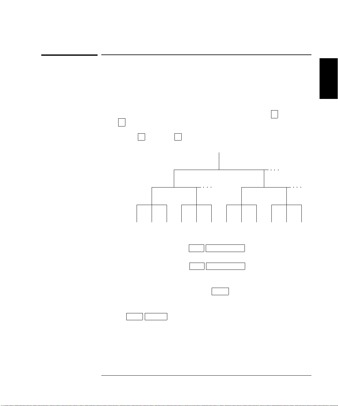
The menu is organized in a top-down tree structure with three
levels (menus, commands, and parameters). You move down
or up
∧ the menu tree to get from one level to the next. Each of the
three levels has several horizontal choices which you can v i ew by
moving left
< or right > .
Menus
Commands
∨
2
Parameters
• To turn on the menu, press Shift Menu On/Off .
• To turn off the men u , pres s Shift Menu On/Off , or press any of
the function or math keys on the top row of front-panel keys.
• To execute a menu command, press Enter .
• To recall the last menu command that was executed,
Shift Recall .
press
29
Page 32
Chapter 2 Front-Panel Menu Operation
A Front-Panel Menu Tutorial
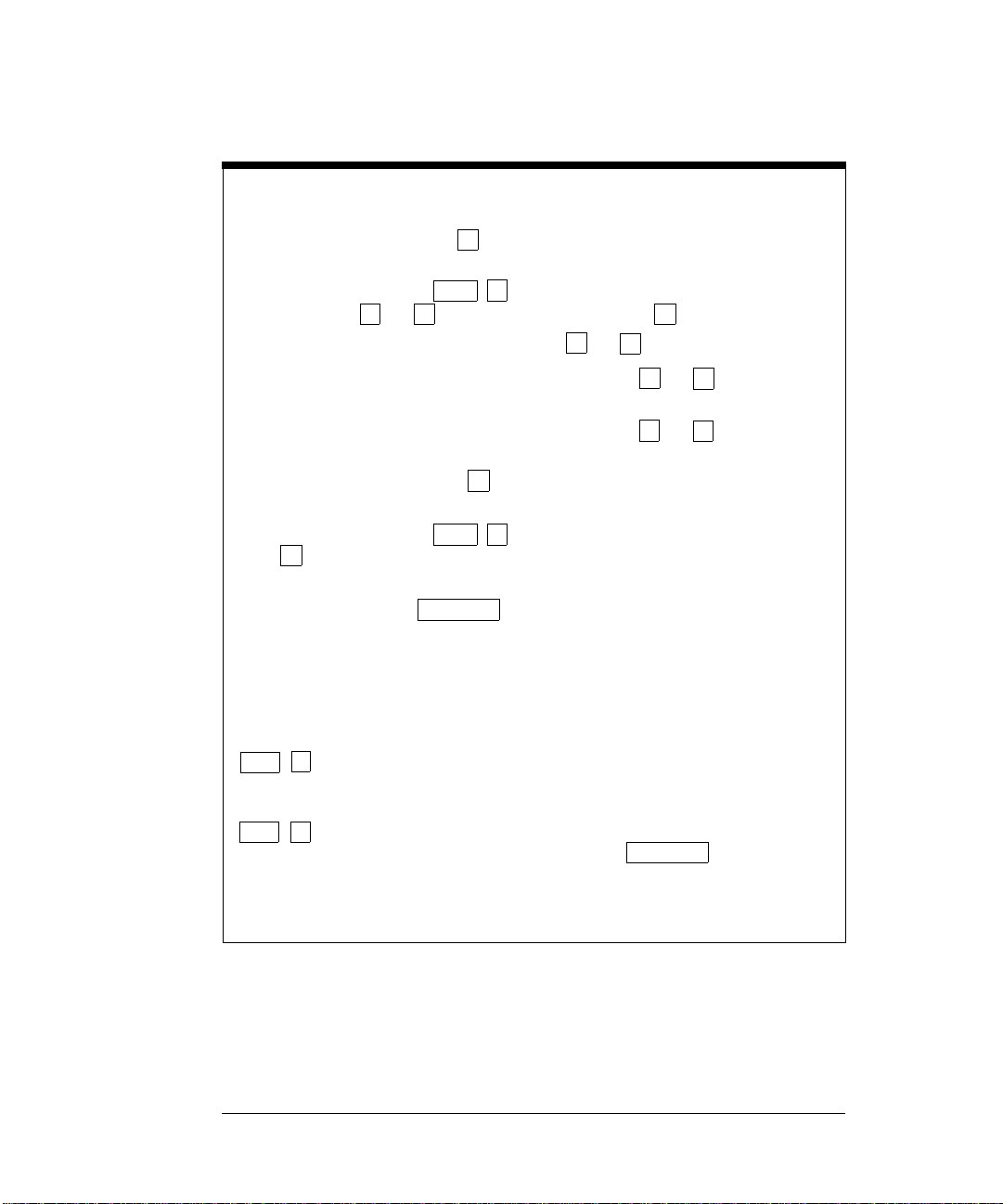
MESSAGES DISPLAYED DURING MENU USE
TOP OF MENU You pressed while on the “menus” level; this is the top level of
the menu and you cannot go any higher.
To turn off the menu, press (Menu On/Off). To move across the choices
on a level, press or . To move down a level, press .
MENUS You are on the “menus” level. Press or to view the choices.
COMMANDS You are on the “commands” level. Press or to view the
command c hoices within the selected menu group.
PARA METER You are on the “parameter” level. Press or to view and edit
the parameter for the selected comm and.
MENU BOTTOM You pressed while on the “parameter” level; this is the bottom
level of the menu and you cannot go any l ower.
To turn off the menu, press (Menu On/Off). To move up a level,
press .
∧
CHANGE SAVED The change made on the “parameter” level is saved. This is
displayed after you press (Menu Enter) to execute the command.
MIN VALUE The value you s pecifie d on the “parameter” level is too small for the
selected command. The minimum value allowed is displayed for you to edit.
MAX VALUE The value you specified on the “parameter” level is too large for the
selected command. The maximu m value allowed is displayed for you to edit.
EXITING MENU You will see this message if you turn off the menu by pressing
(Menu On/Off) or a front-panel function/math key. You did not edit any values
Shift
<
on the “para meter” level and changes were NO T saved.
< >
∧
Shift <
∨
Shift
Auto/Man
<
<
>
<
<
∨
>
>
NOT ENTERED You will see this message if you turn off the menu by pressing
(Menu On/Off) or a front-panel function/math key. You did some editing of
<
Shift
parameters but the changes were NOT saved. Press (Menu Enter)
to save changes made on the “parameter” level.
NOT RELEVANT The selected math operation is NOT valid for the function in use.
Auto/Man
30
Page 33
Chapter 2 Front-Panel Menu Operation
A Front-Panel Menu Tutorial
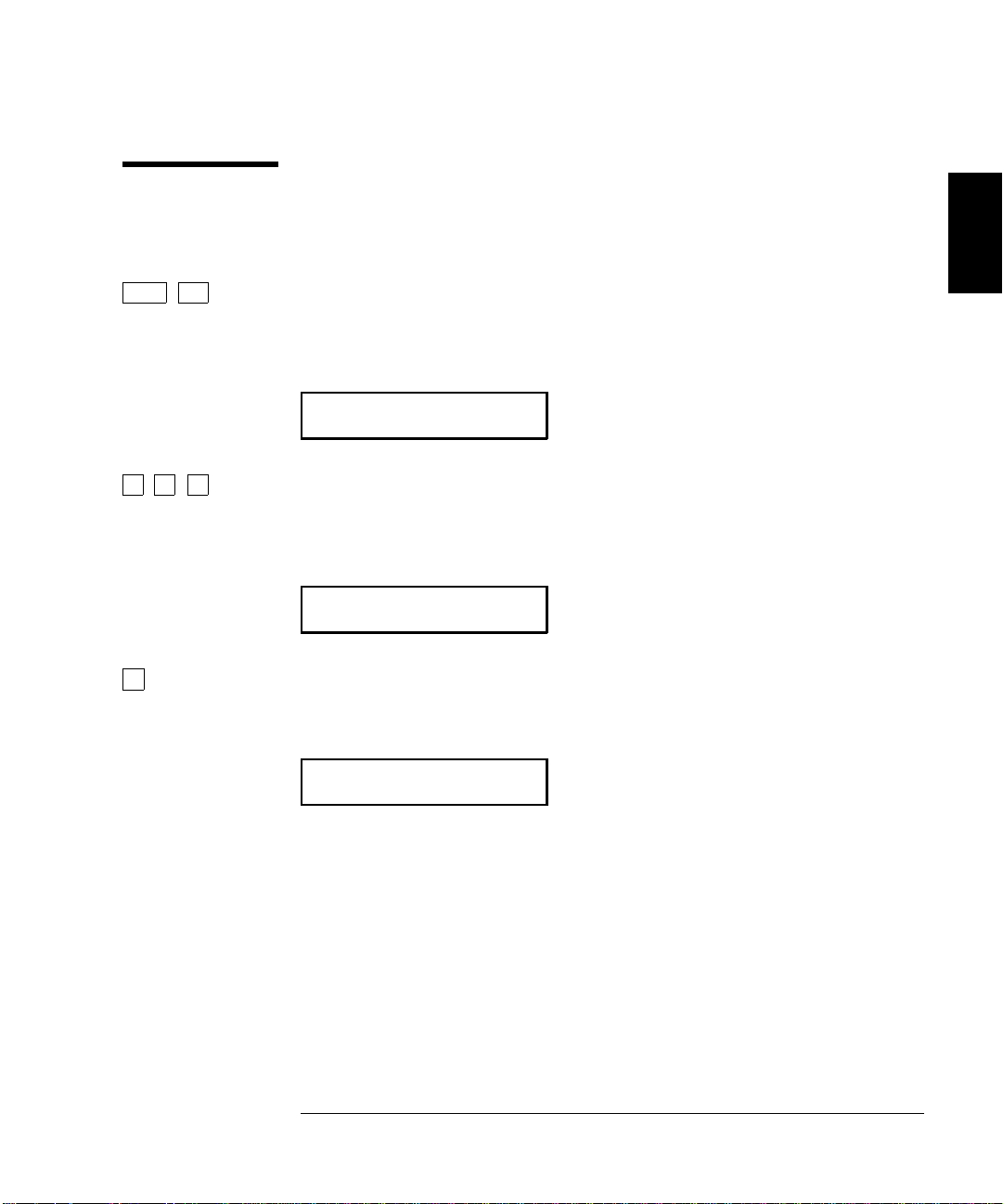
Menu Example 1 The following steps show yo u h ow to turn on the men u, mo ve up or
down between levels, move across the choices on each level, and turn off
the menu. In this example, you will turn off the front-panel beeper.
On/Off
Shift <
> >
∨
>
1 Turn on the menu.
You enter the menu on the “menus” level. The
MEAS MENU is your first
choice on this level.
A: MEAS MENU
2 Move across to the SYS MENU choice on this level.
There are six menu grou p choi c es a vaila ble on the “men u s” level. Each
choice has a letter prefix for eas y ident ifica tion (
A: , B: , etc.).
D: SYS MENU
3 Move down to the “commands” level within the SYS MENU.
RDGS STORE command is your first choice on this level.
The
1: RDGS STORE
2
31
Page 34
Chapter 2 Front-Panel Menu Operation
A Front-Panel Menu Tutorial
> > >
> >
∨
>
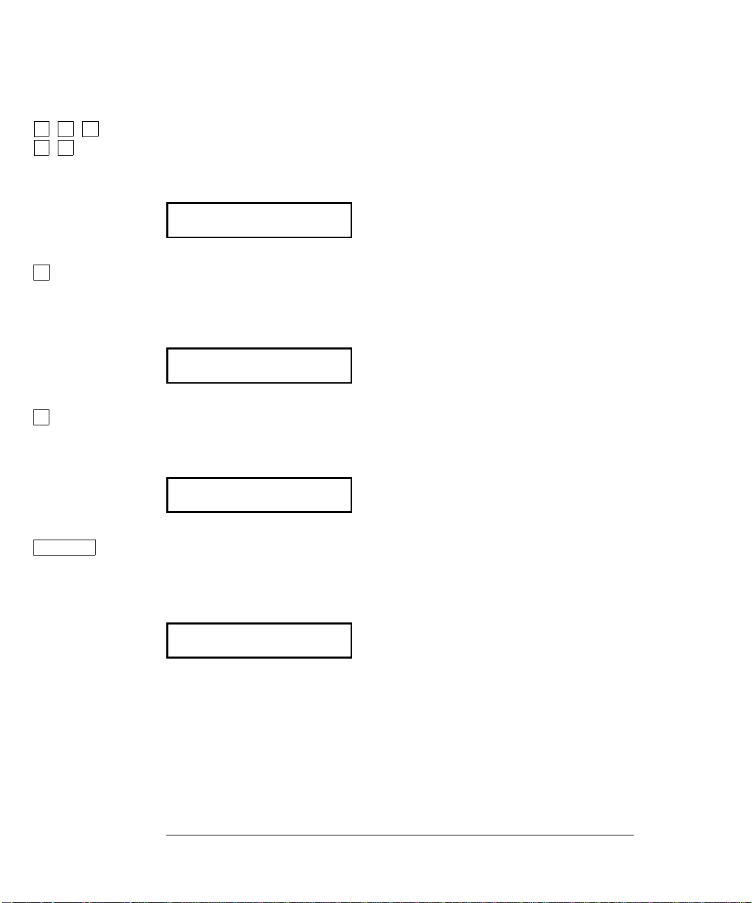
4 Move across to the BEEP command on the “commands” level.
There are eight command choices available in the
choice on this level has a n umber prefi x for ea sy identifi cation (
SYS MENU. Each
1: , 2: , etc.).
6: BEEP
5 Move down a level to the BEEP parameter choices.
The first parameter choice is “
setting is stored in non-volatile memory and “
ON” for the BEEP command (the beeper
ON” is the factory setting).
ON
6 Move across to the “OFF” choice.
There are two parameter choices for
BEEP.
OFF
Auto/Man
ENTER
7 Save the change and turn off the menu.
The multimeter beeps and displays a message to show that the change
is now in effect. You are then exited from the menu.
CHANGE SAVED
32
Page 35
Chapter 2 Front-Panel Menu Operation
A Front-Panel Menu Tutorial
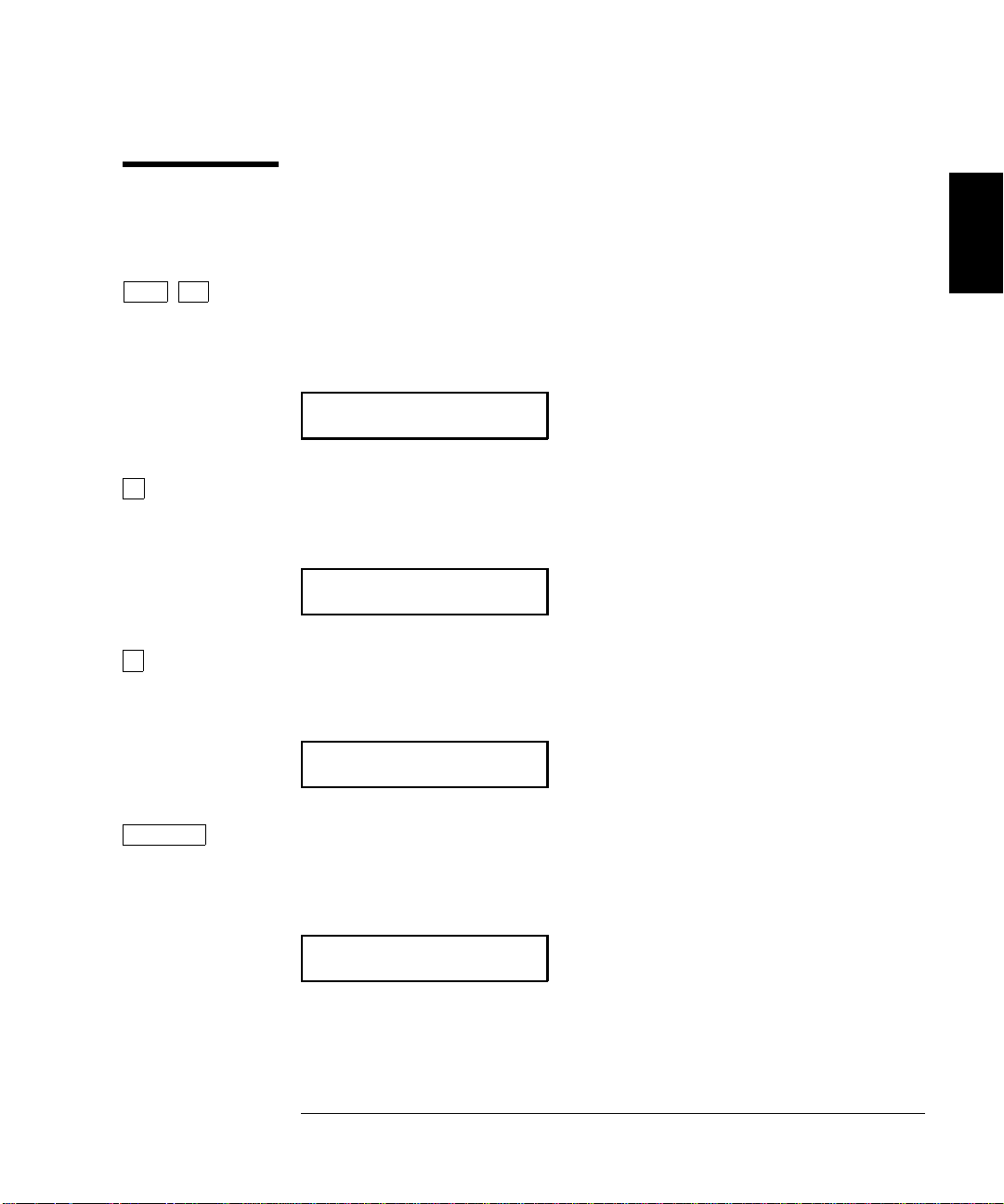
Menu Example 2 The following exercise dem onstrates how to use the menu recall feature
as a shortcut to set the
BEEP command back to its original setting.
You must perform the steps in Exam ple 1 before you start this example.
Shift
∨
>
Recall
>
1 Use menu recall to return to the
This returns you to the
BEEP command, which was the last command
BEEP command.
used before you exi ted t he me nu i n the Exa mple 1.
6: BEEP
2 Move down to the BEEP parameter choices.
The first parameter choice is “
OFF” (the current sett i ng from Example 1).
OFF
3 Move across to the “ON” choice.
Set the parameter back to its original value.
ON
2
Auto/Man
ENTER
4 Save the change and turn off the menu.
The multimeter beeps and displays a message to show that the change
is now in effect. You are then exited from the menu.
CHANGE SAVED
33
Page 36
Chapter 2 Front-Panel Menu Operation
A Front-Panel Menu Tutorial
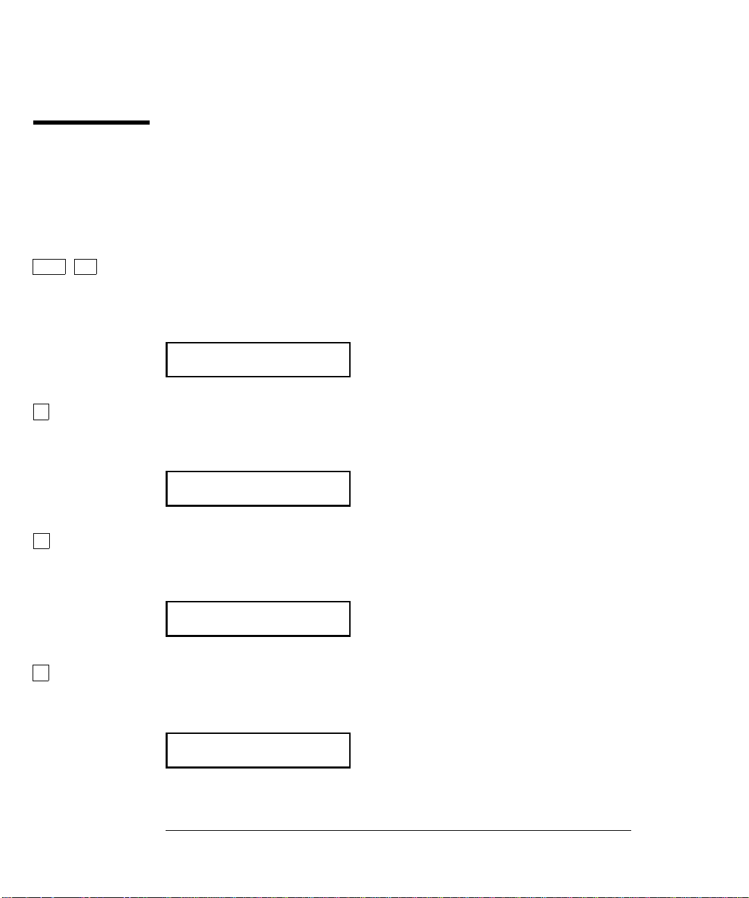
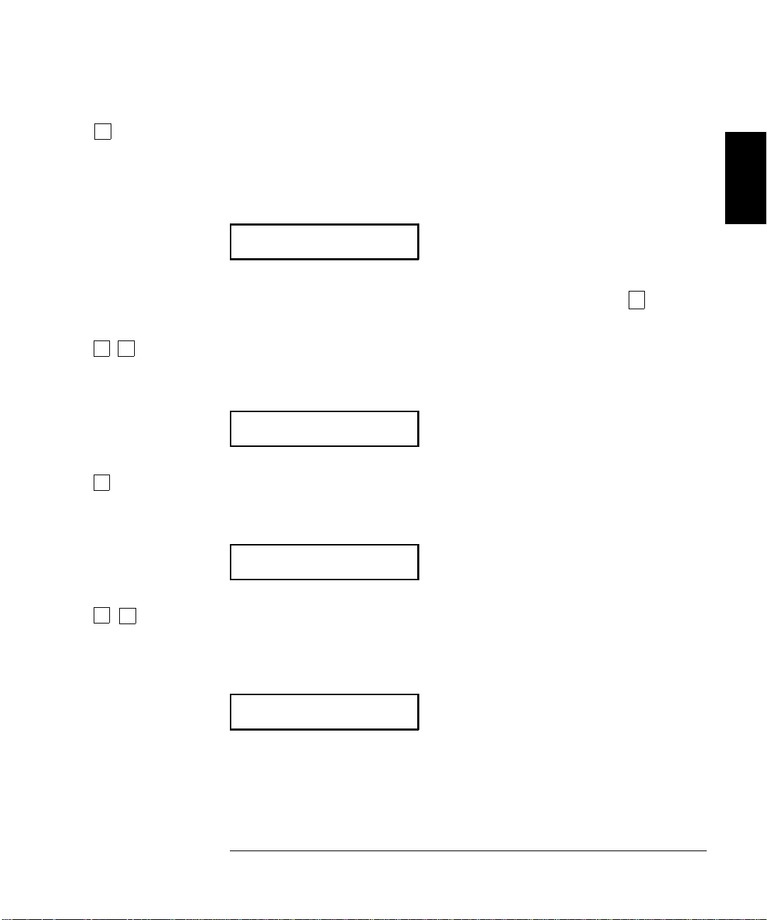
Menu Example 3 Some commands in the menu require that you enter a numeric
parameter value. The following steps show you how to enter a number
in the menu. For this example, you will set the null value to –2.0 volts.
Make sure the mul timeter is in the dc vo ltage function with 5
1
resolution displayed. Disconnect all inputs to the multimeter.
On/Off
Shift <
1 Turn on the menu.
⁄
digits of
2
>
∨
>
You enter the menu on the “menus” level. The
MEAS MENU is your first
choice on this level.
A: MEAS MENU
2 Move across to the MATH MEN U choice on this level.
There are six menu grou p choi c es a vaila ble on this level.
B: MATH MENU
3 Move down to the “commands” level within the MATH MENU.
The
MIN–MAX command is your first choice on this level.
1: MIN-MAX
4 Move across to the NULL VALUE command on this level.
There are seven command choices available within the
2: NULL VALUE
34
MATH ME NU.
Page 37
Chapter 2 Front-Panel Menu Operation
A Front-Panel Menu Tutorial
∨
∨ ∨
>
5 Move down to edit the NULL VALUE parameter.
The null value should be 0.0 Vdc when you come to this point in the
menu for the first time. For this example, you will set the null value
to –2.0 volts.
∧000.000 mVDC
When you see the flashing “∧” on the left side of the display, you can
abort the edit and return to the “commands” level by pressing
6 Make the number negative.
The leftmost character on the display toggles between + and – .
-000.000 mVDC
7 Move the flashing cursor over to edit the first digit.
Notice that the leftmost digit is flashing.
∧ .
2
∧
∧
-000.000 mVDC
8 Increment the first digit until “ 2 ” is displayed.
You decrement or increment each digit independently. Neighboring
digits are not affected.
-200.000 mVDC
35
Page 38

Chapter 2 Front-Panel Menu Operation
A Front-Panel Menu Tutorial
< <
∧
Auto/Man
ENTER
9 Move the flashing cursor over to the “units” location.
Notice that the units are flashing on the right side of the display.
-200.000 mVDC
10 Increase the displayed number by a factor of 10.
Notice that the position of the decimal point changes and the displayed
number increases by a factor of 10.
-2.000,00 VDC
11 Save the change and turn off the menu.
The multimeter beeps and displays a message to show that the change
is now in effect. You are then exited from the menu.
CHANGE SAVED
Keep in mind that math null is turned on and –2.0 volts i s u sed a s
the null va lu e for m ea su r e men ts. To clear the nu ll value, pres s
Null .
This is the end of the front-panel menu tutorial. The remainder of the
chapter discusses several of the most common front-panel operations.
36
Page 39
Chapter 2 Front-Panel Menu Operation
To Turn Off the Comma Separator
To Turn Off the Comma Separator
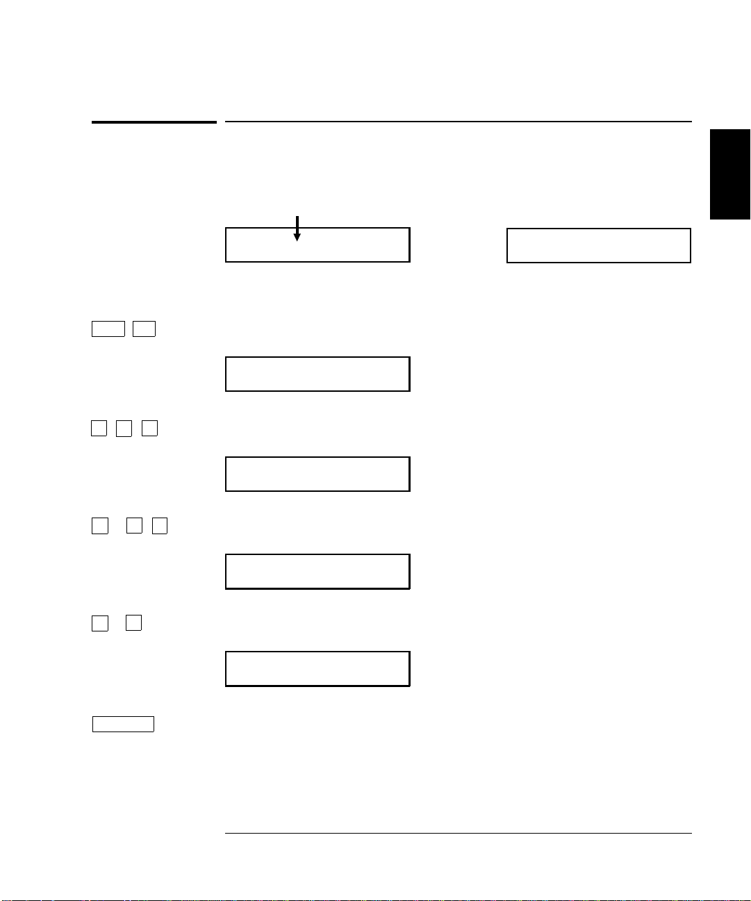
The multimet er can display re adi n gs on the fr on t panel w it h or with ou t
a comma separator. The following steps show how to disable the comma.
2
On/Off
Shift <
>
>
<
∨
>
∨
>
<
08.241,53 VDC
With comma separator
(factory setting) Without comma separator
08.24153 VDC
1 Turn on the menu.
A: MEAS MENU
2 Move across to the SYS MENU choice on the “menus” level.
D: SYS MENU
3 Move down a level and then across to the COMMA command.
7: COMMA
4 Move down a level and then move across to the “OFF” choice.
Auto/Man
ENTER
OFF
5 Save the change and turn off the menu.
The comma separator setting is stored in non-volatile memory, and
does not ch ange when pow er has been off or a fter a r em ote interface reset.
37
Page 40
Chapter 2 Front-Panel Menu Operation
To Make Null (Relative) Measurements
To Make Null (Relative) Measurements
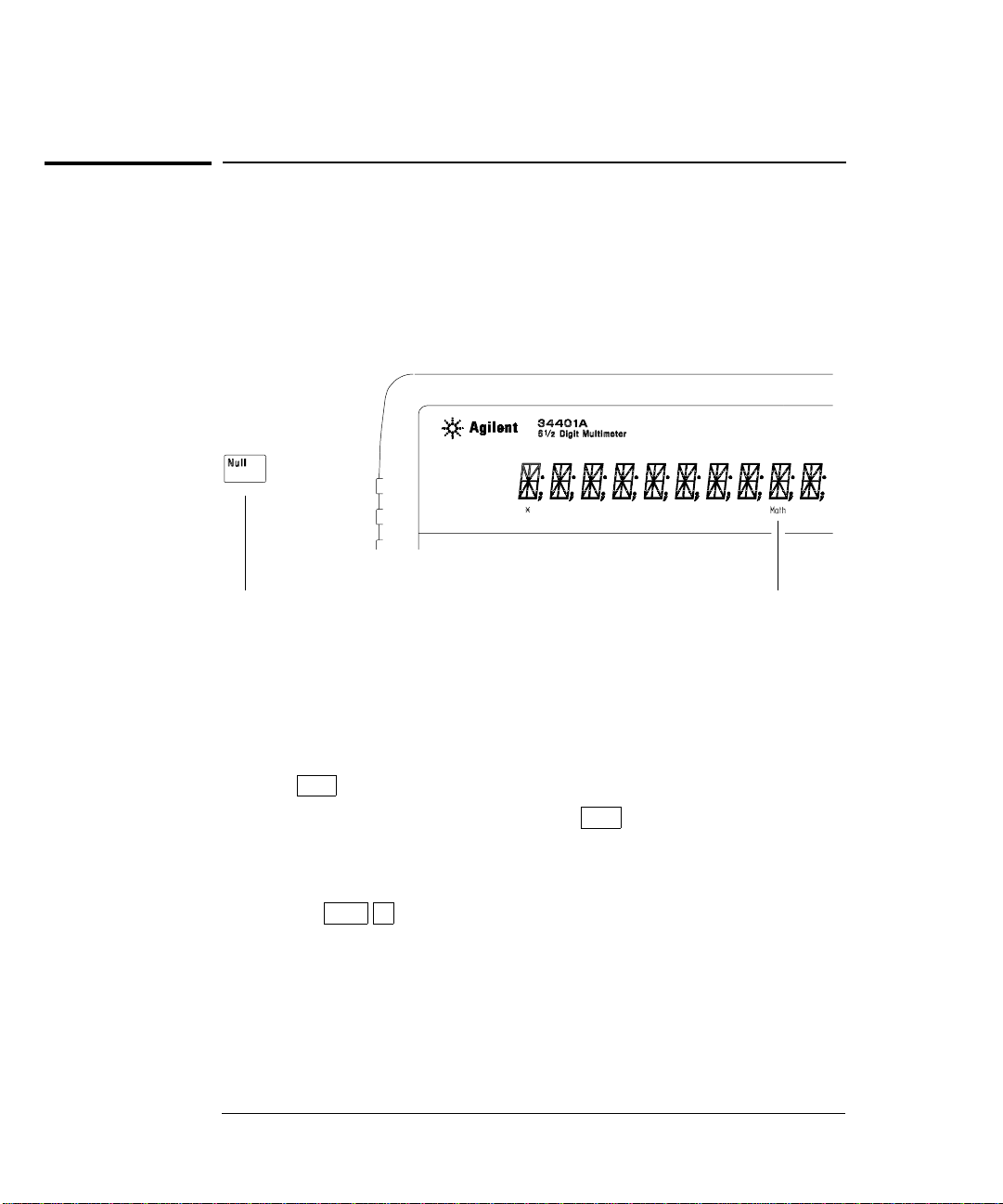
Each null measurement, also called relative, is the difference between a
stored null value a nd the i n put signal.
Result = reading – null value
To read / edit the null value, use the MATH menu.
Enables null ope rati on;
Press again to di sable.
• You can make null m easurements wi t h any function except
Math annunciator is on when
null operation is enabl ed.
continuity, diode, or ratio. The null operation is local to the selected
function ; when yo u chan g e fu nct ion s , null is disab led.
• To null the test lead resistance for more accurate two-wire ohms
measurements, short the ends of the test leads together and then
Null .
press
• The first reading taken after you press Null is stored as the null
value in the Null Register. Any previously stored value is
replaced with the new value.
• After enabling null, you can edit the stored null value by
pressing
NULL VAL UE ” command in the MATH MENU (only if null is
“
Shift > (Menu Recall). This takes you to the
enabled). Go down to the “parameter” level, and then edit the
displayed value.
• The null register is c lear ed wh en yo u chan g e fu nct ion s, tu rn nul l off,
turn off the power, or perform a remote interface reset.
38
Page 41
Chapter 2 Front-Panel Menu Operation
To Store Minimum and Maximum Readings
To Store Minimum and Maximum Readings
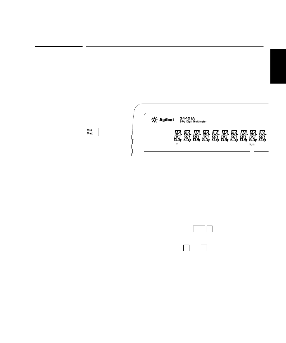
You can store the minimum and maximum readings during a series
of measuremen t s. The follow i ng dis cus s ion show s how to rea d the
minimum, maximum, average, and reading count.
To read the minimum, ma ximu m, average, and count,
use the MATH menu.
2
Enables min-max operation;
Press again to dis able.
• You can use min-max with any fu nction ex cept c ontinuity or diode test.
Math annunciator is on when
min-max operation is enabled.
The min-max operation is local to the selected function; when you
change functions, min-max is disabled.
•• After enabling min-max, you can read the stored minimum,
maximum, average, and count by pressing
This takes you to the “
MIN–MAX” command in the MATH MENU
Shift > (Menu Recall).
(only if min-max is ena bled). Go down to the “parameter” level,
and then read the values by pressing
• The stored valu es are c l ear ed when yo u tu rn min- m ax off , turn off t he
< or > .
power, or perform a remote interface reset.
• The average is of all re a din gs t aken sin c e min- m ax w as ena bl ed (n ot
just the average of the stored minimum and maximum). The count is
the total number of readings taken since min-max was enabled.
39
Page 42
Chapter 2 Front-Panel Menu Operation
To Make dB Measurements
To Make dB Measurements
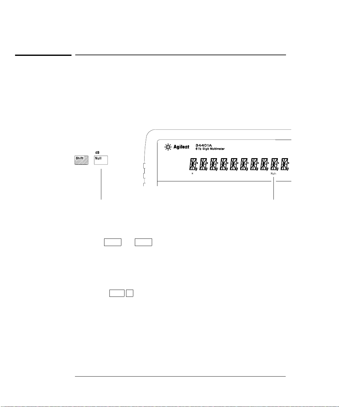
Each dB measurement is the difference between the input signal and a
stored relative value, with both values converted to dBm.
dB = reading in dBm – relative value in dBm
To read / edit the dB relativ e value, use the MATH menu .
Enables dB operat ion;
Press again to disa bl e.
• Select DC V or AC V .
• The first reading taken after you enable dB measurements is
Math annunciator is on when
dB operation is enabl ed.
converted to dBm and is stored as the relative value in the
dB Relative Register. Any previously stored value is replaced
with the new value.
• After enabling dB operations, you can edit the relative value by
pressing
command in the
Shift > (Menu Recall). This takes you to the “dB REL”
MATH MENU (only if dB is enabled) . Go down to
the “p a rame t er ” level, and then edit th e valu e dis pla yed.
• The register is cl ear ed when yo u c hang e fu nc tion s , tu rn dB off,
turn off the power, or perform a remote interface reset.
40
Page 43
Chapter 2 Front-Panel Menu Operation
To Make dBm Measurements
To Make dBm Measurements
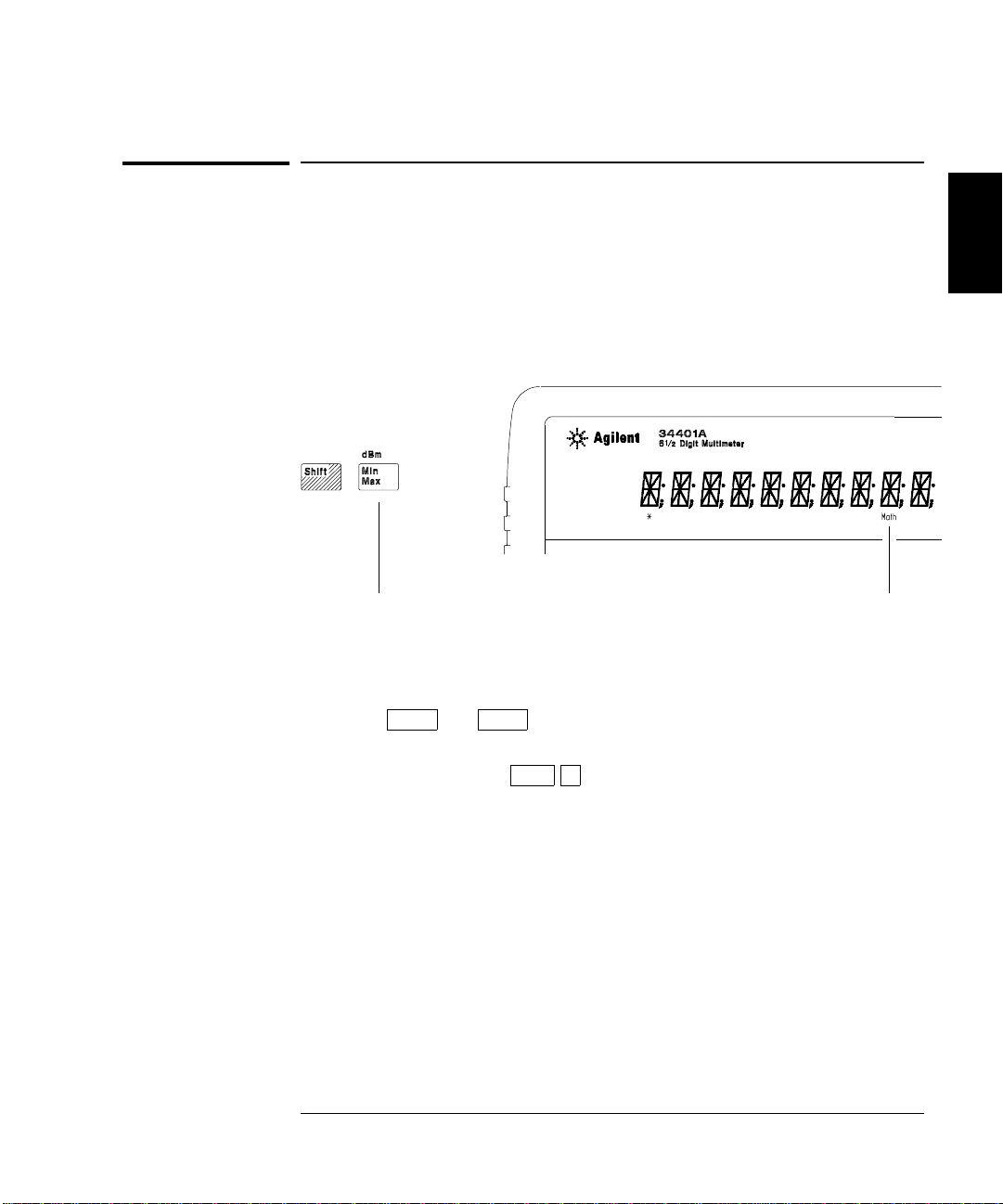
The dBm operation calculates the power delivered to a resistance
referenced to 1 milliwatt.
dBm = 10
× Log
( reading
10
2
/ reference resistance / 1 mW )
To read / edit the dBm refer enc e res is tance,
use the MATH menu.
2
Enables dBm oper at ion;
Press again to dis able.
• Select DC V or AC V .
• The factory setting for the reference resistance is 600 Ω. To select a
different value, press
operations. This takes you to the “
MATH MENU (only if dBm is enabled).
Shift > (Menu Recall) after enabling dBm
dBm REF R” command in the
Math annunciator is on when
dBm operation is enabled.
Go down to the “ p ar am eter” lev el, an d then selec t a value: 50, 75,
93, 110, 124, 125, 135, 150, 250, 300, 500, 600, 800, 900, 1000,
1200, or 8000 ohms.
• The reference resistance is stored in non-volatile memory, and does no t
change when power has been off or after a remote interface reset.
41
Page 44
Chapter 2 Front-Panel Menu Operation
To Trigger the Multimeter
To Trigger the Multimeter
You can trigger the multimeter from the front panel using single trigger
or auto trigger.
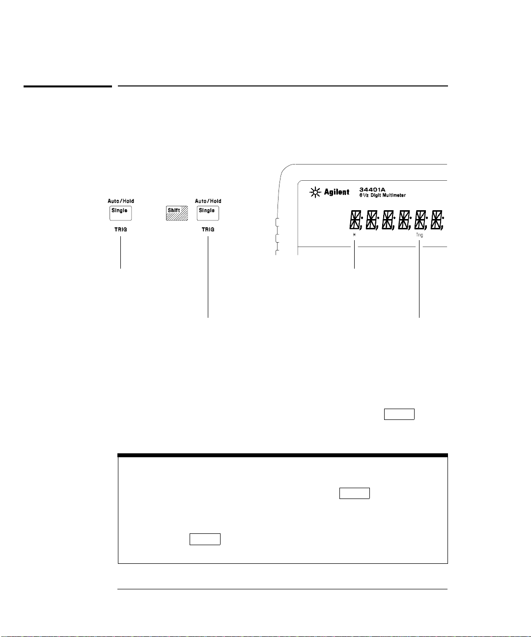
Enables single trigger
and triggers the multimeter.
Toggles betwe en aut o trigger
and reading hold.
• Auto trigger ing is ena bled w he n y ou tur n on the mu l ti met er. Not ic e
that the
• Single triggering takes one reading each time you press Single
∗ (sample) annunciator turns on during each measurement.
and then waits for the next trigger. Continue pressing this key to
trigger the multimeter.
Using an External Trigger
The external trigger mode is also enabled by pressi ng . It is like
the single trigger mode except that you apply a tri gger pulse t o t he re ar-panel
Ext Trig terminal. The mult imet er is trigger ed on t he negative edge of a
TTL pulse.
The front-panel key is disabled when in remote.
Single
(sample) annunciator is on
∗
during each measur ement .
Trig annunciator is on when the
multimeter is waiting f or singl e
trigger (auto trigge r disabled).
Single
42
Page 45
Chapter 2 Front-Panel Menu Operation
To Use Reading Hold
To Use Reading Hold
The reading hold feature allows you to capture and hold a stable
reading on the display. When a stable reading is detected, the
multimeter emits a beep and holds the value on the display.
To adjust the rea di ng hold sensitivity band,
use the TRIG men u.
2
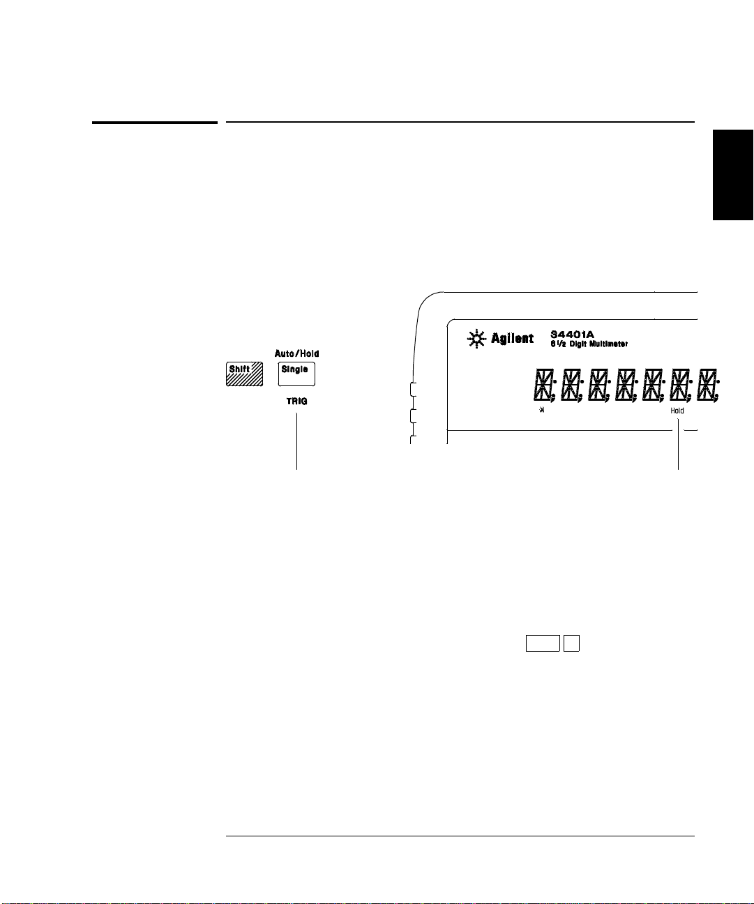
Toggles between aut o trigger
and reading hold.
• Reading hold has an adjustable sen s iti vit y b an d to allow you to
Hold annunciator is on when
reading hold is enabled.
select which readings are considered stable enough to be displayed.
The band is expres sed as a perc en t of re ad in g on the s elec ted r ang e.
The multimeter will capture and display a new value only after three
consecutiv e r ea din g s are wit h in the b and .
• The default band is 0.10% of reading. After enabling reading hold,
you can choose a different band by pressing
Shift >
(Menu Recall). This takes you to the “READ HOLD” c ommand in
TRIG MENU (only if read ing hol d is enable d ).
the
Go down to the “ p ar am eter” lev el, an d then selec t a value:
0.01%, 0.10%, 1.00%, or 10.00% of reading.
• The sensitivity band is stored in volatile memory; the multimeter
sets the band to 0.10% of reading when power has been off or after a
remote interface reset.
43
Page 46
Chapter 2 Front-Panel Menu Operation
To Make dcv:dcv Ratio Measurements
To Make dcv:dcv Ratio Measurements
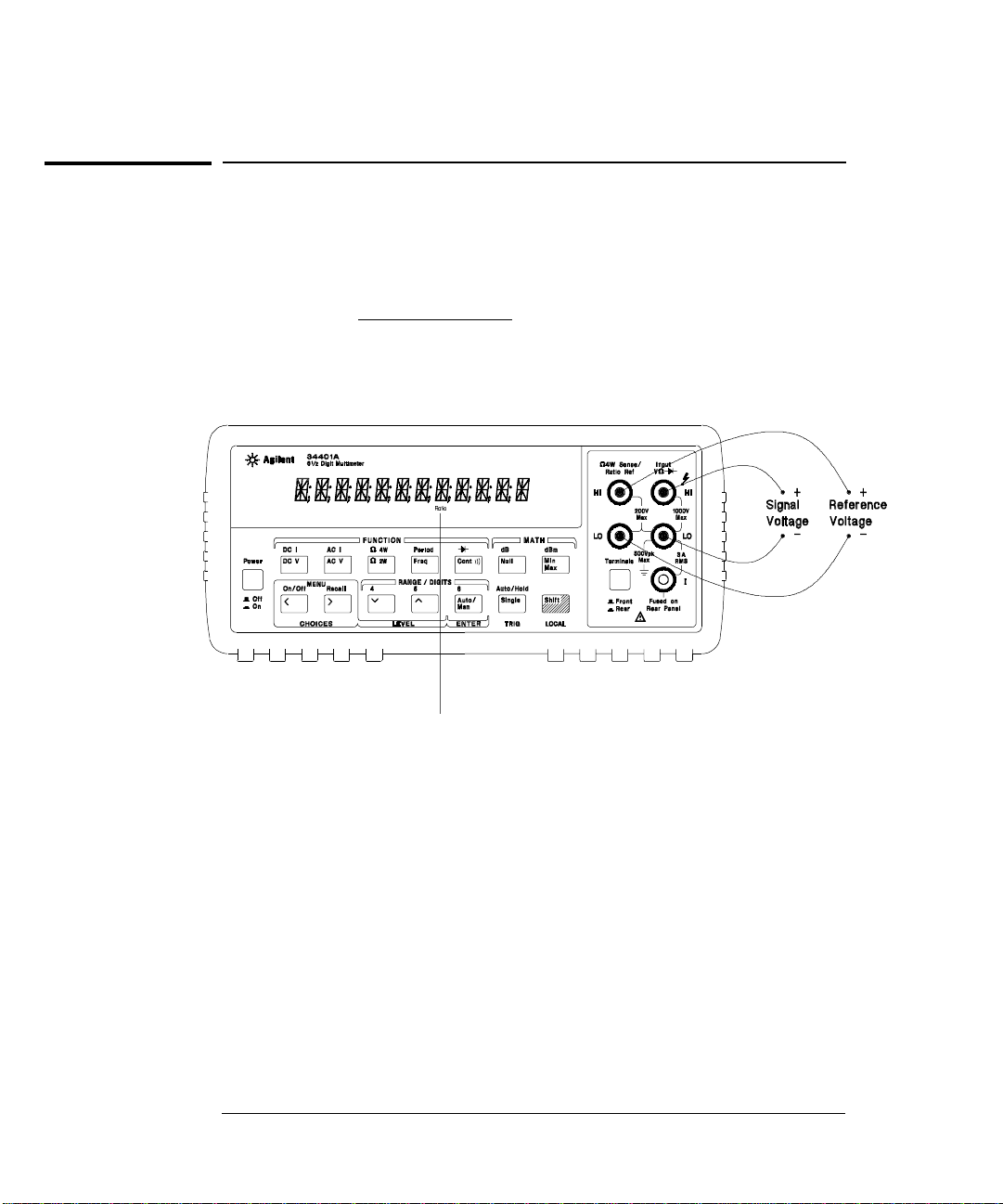
To calculate a ratio, the multimeter measures a dc reference voltage
applied to the
terminals.
To enable ratio me asurem ent s, use the MEAS menu.
Sens e terminals and the voltage applied to the Input
Ratio =
dc signal voltage
dc reference voltage
Ratio annunciator is on when
• At the Sense terminals, the reference voltage measurement function
ratio measurem ents ar e enabled.
is always dc voltage and has a maximum measurable input of
±12 Vdc. Autoranging is automatically selected for reference voltage
measurements on the
• The Input LO and Sense LO terminals must have a common reference
and cannot hav e a volta ge di ff er en ce great er than
• The specified measurement range applies only to the signal connected
Input terminals. The signal on the Input ter minals can be any
to the
Sens e terminals.
±2 volts.
dc voltage up to 1000 volts.
44
Page 47
On/Off
Shift <
<
∨
<
Chapter 2 Front-Panel Menu Operation
To Make dcv:dcv Ratio Measurements
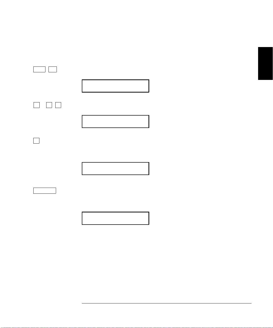
The following steps show yo u h ow to selec t the ratio function using the
front-panel menu.
1 Turn on the menu.
A: MEAS MENU
2 Move down a level and then across to the RATIO FUNC command.
4: RATIO FUNC
2
∨
Auto/Man
ENTER
3 Move down to the “parameter” level.
For this command, there is only one choice on this level.
DCV:DCV
4 Select the ratio function and turn off the menu.
Notice that the
Ratio annunciator turns on.
CHANGE SAVED
To disabl e rat io measurement s, select a different measurement function
by pressing any front-panel function key.
45
Page 48
Chapter 2 Front-Panel Menu Operation
To Use Reading Memory
To Use Reading Memory
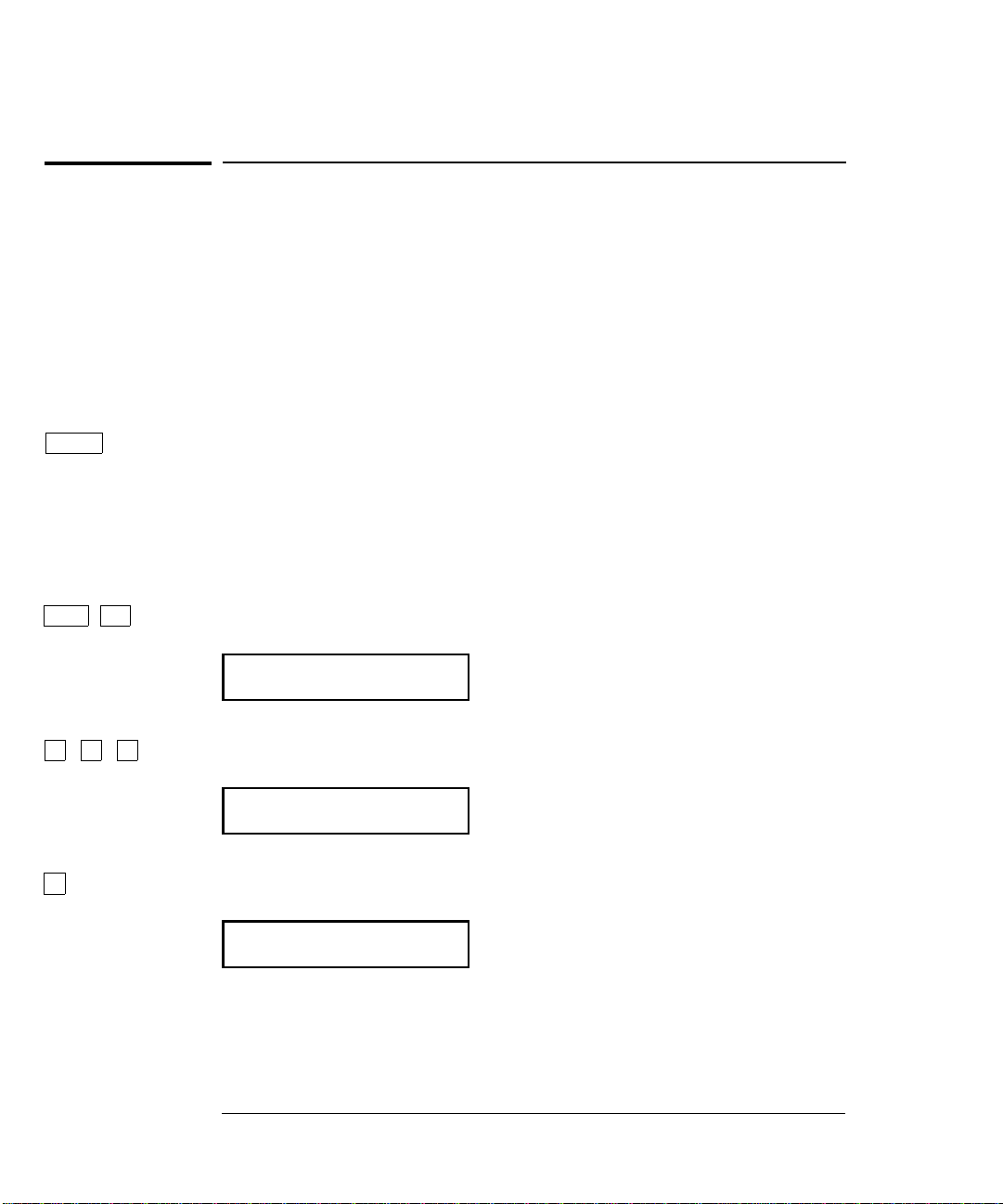
The multimeter can store up to 512 readings in internal memory.
The following steps demonstrate how to store readings and retrieve them.
1 Select the func tio n.
Select any measurement functi on. You can also sele ct Nu ll, Min–Max,
dB, dBm, or limit test. You can change the function at any time during
reading memory.
Single
On/Off
Shift <
> > >
∨
2 Select the single trigger mode.
Notice that the
Tri g annunc iator turns on. When reading memory is
enabled, read i ngs are s tor ed wh en yo u tr igger the mul tim eter .
For this example, single triggering is used to store readings. You can also
use auto triggering or reading hold.
3 Turn on the menu.
A: MEAS MENU
4 Move across to the SYS MENU choice on this level.
D: SYS MENU
5 Move down to a level to the RDGS STORE command.
1: RDGS STORE
46
Page 49
Chapter 2 Front-Panel Menu Operation
To Use Reading Memory
Auto/Man
ENTER
Single
Single
Single
Recall
Shift >
> ∨
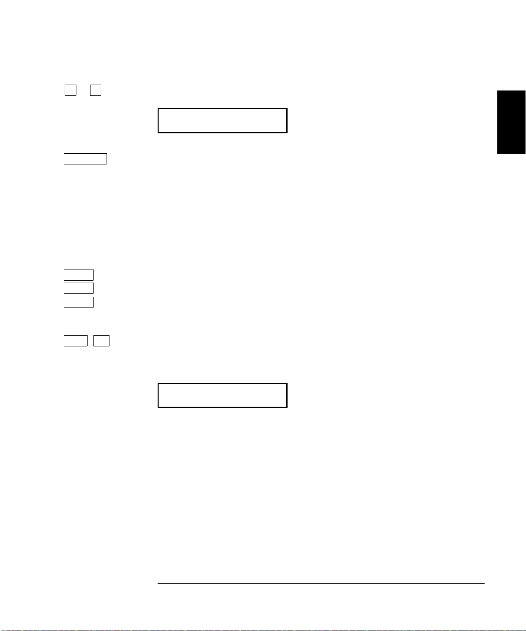
6 Move down a level and then across to the “ON” choice.
ON
2
7 Save the change and exit the menu.
Notice that the
multimeter is ready to store readings. Up to 512 readings can be stored
in fir st-i n-f irs t-ou t (
will turn off.
Readings are preserved until you re-enable reading memory at another
time, tur n of f the power, or perform a remote interface reset.
8 Trigger the multimeter three times.
This stores three readings in memory.
9 Use menu recall to retrieve the stored readings.
This takes you to the “
Mem (memory) annun ci a t or turns on to indicat e that the
FIFO) order. When memory is full, the Mem annunciator
SAVED RDGS” command in the SYS ME NU.
2: SAVED RDGS
47
Page 50

Chapter 2 Front-Panel Menu Operation
To Use Reading Memory
∨
>
>
On/Off
Shift <
10 Move down a level to view the first stored reading.
Reading memory is automatically turned off when you go to the
“parameter” level in the menu.
The first readi ng displayed is the first reading that was stored (FIFO).
If no readings are s tor ed in mem or y, “
readings are displayed with their units (
EMPTY” is displayed. The stored
µ, m, k, etc.) when appropriate.
For example:
Reading number
10.31607K: 1
Exponent
11 Move across to view the two remaining stored readings.
The readings a re stor ed horizontally on the “paramet er ” level.
If you press
< when you get to the “parameter” level, you will see the
last reading and you will know how many readings were stored.
12 Turn off the menu.
EXITING MENU
48
Page 51

3
3
Features and
Functions
Page 52

Features and Functions
You will find that this chapter makes it easy to look up all the details
about a particular feature of the multimeter. Whether you are operating
the multimeter from the front panel or from the remote interface, this
chapter will be useful. This chapter is divided into the following sections:
• Measurement Configuration, starting on page 51
• Math Operations, starting on page 63
• Triggering, starting on page 71
• System-Rela ted O per a tion s , star ti ng on page 84
• Remote Interface Configuration, starting on page 91
• Calibration Overview, starting on page 95
• Operator Maintenance, starting on page 1 00
• Power-On and Reset State, o n page 101
Some knowledge of the front-panel menu will be helpful before you read
this chapter. If you have not already read chapter 2, “Front-Panel Menu
Operation,” starting on page 25, you may want to read it now. Chapter 4 ,
“Remote Interface Reference,” starting on page 103, lists the syntax for
SCPI commands available to program the multimeter.
the
Throughout this manual, the following conventions are used for
SCPI command syntax for remote interface programming.
• Square brackets ( [ ] ) indicate optional keywords or parameters.
• Braces ( { } ) enclose parameters within a command string.
• Triangle brackets ( < > ) indicate that you must substitute a value
for the enclosed parameter.
• A vertical bar (
|
) separates multiple parameter choices.
50
Page 53

Chapter 3 Features and Functions
Measurement Configuration
Measurement Configuration
This secti on contains information to hel p you configure the multimeter
for making measurements. You may never have to change any of the
measurement parameters discussed here, but they are provided to give
you the flexibility you might need.
AC Signal Filter
The multimet er uses thr ee diffe re nt a c filte rs whi c h enable y ou to eith er
optimize low frequency accuracy or achieve faster ac settling times.
The multimeter selects the slow, medium, or fast filter based on the
input freque ncy t ha t you specify.
Applies to ac vo ltage and ac current m easurements only.
3
Input Frequency
3 Hz to 300 kHz
20 Hz to 300 kHz
200 Hz to 300 kHz
• The ac filter selection is stored in volatile memory; the multimeter
AC Filter Selected
Slow f ilter
Mediu m filt er (d ef au lt )
Fast filter
Settling Time
7 seconds / reading
1 reading / second
10 readings / second
selects the medium filter (20 Hz) when pow er has been off or aft er a
remote interface reset.
• Front-Panel Operation: Select from the menu the slow filt er (3 Hz),
medium filter (20 Hz), or fast filter (200 Hz). The default is the
medium filter.
1: AC FILTER (MEAS MENU)
• Remote Interface Operation: Specify the lowest frequ en cy ex pec ted in
the input signal. The multimeter selects the appropriate filter based
on the frequency you specify (see table above). The
CONFigure and
MEASure? commands select the 20 Hz filter.
DETector:BANDwidth {3|20|200|MINimum|MAXimum}
51
Page 54

Chapter 3 Features and Functions
Measurement Configuration
Continuity Threshold R esistance
When measuring continuity, the multimeter emits a continuous tone if
the measured resistance is less than the threshold resistance. You can
set the threshold to any value between 1
The threshold resistance is adjustable only from the front panel .
• The threshold resistance is stored in non-v olatile mem or y, an d does not
change when power has been off or after a remote interface reset.
• The factory setting for the threshold resistance is 10 Ω.
• After enabling the continuity function, you can select a different
threshold resistance by pressi ng
Ω and 1000 Ω.
Shift > (Menu Recall).
2: CONTINUITY (MEAS MENU)
See also “To Test Conti nuity,” on page 19.
∧0010 OHM
52
Page 55
Chapter 3 Features and Functions
Measurement Configuration
DC Input Resistance
Normally, the multimeter’s input resistance is fixed at 10 MΩ for all
dc voltage ranges to mini mize n oi se pi cku p. To r edu c e the eff ec ts of
measurement loading errors, you can set the input resistance to greater
than 10 G
Applies to dc voltage meas ureme nts an d is d isab led for all oth er fu nctions .
Fixed Resistance ON (default)
Fixed Resistance OFF
• The input resi stan c e set ting is stor ed in volatile memory; the
multimeter selects 1 0 M
has been off or after a remote interface reset.
Ω for the 100 mVdc, 1 Vdc, and 10 Vdc ranges.
Input Resistance Input Resistance
100mV, 1V, 10V ranges 100V, 1000V ranges
10 MΩ 10 MΩ
> 10 GΩ 10 MΩ
Ω (for all dc voltage ranges) wh en pow er
3
• Front-Panel Operation: Select from the menu the 10 MΩ mode (fixed
resistance fo r all d c volt a ge ranges) or the >10 G
is 10 M
• Remote Interface Operation: You can enable or disable the automatic
input resistance mode. With
is fixed at 10 M
is set to >10 G
Ω.
3: INPUT R (MEAS MENU)
AUTO OFF (default), the input resistance
Ω for all ranges. With AUTO ON, the input resistance
Ω for the three lowest dc voltage ranges. Th e CONFigure
Ω mode. The default
and MEASure? commands automatically turn AUTO OFF.
INPut:IMPedance:AUTO {OFF|ON}
53
Page 56

Chapter 3 Features and Functions
Measurement Configuration
Resolution
Resolution is expr es sed in t erm s of number of digits the multimeter can
measure or display. You can set the resolution to 4, 5, or 6 full digits,
plus a “
accuracy and improve noise rejection, select 6
measurement speed, select 4
Applies to all measurement functions. The resolution for the math
operations (null, min-max, dB, dBm, limit test) is the same as the
resolution for the measu rem ent function i n use.
The correspondence between the number of digits selected and the
resulting integration time (in power line cycles) is shown below.
The autozero mode is set indirectly when you set the resolution.
See also “Autozero,” on page 59.
1
⁄
” digit which can only be a “0” or “1”. To increase measurement
2
1
⁄
digits.
2
1
⁄
digits. To increase
2
Resolution Choices
Fast 4 Digit
* Slow 4 Digit
Fast 5 Digit
* Slow 5 Digit (default)
* Fast 6 Digit
Slow 6 Digit
* These settings configure the multimeter just as if you had pressed
the corresponding “DIGITS” keys from the front panel.
Integration Time
0.02 PLC
1 P LC
0.2 PLC
10 PLC
10 PLC
100 PLC
Resolutio n is local to t he selected func tion. This means t hat you can
select the r esolutio n for each fun ction inde pendently. T he multime ter
remembers the resolution when you switch between functions.
54
Page 57
5 digits
Chapter 3 Features and Functions
Measurement Configuration
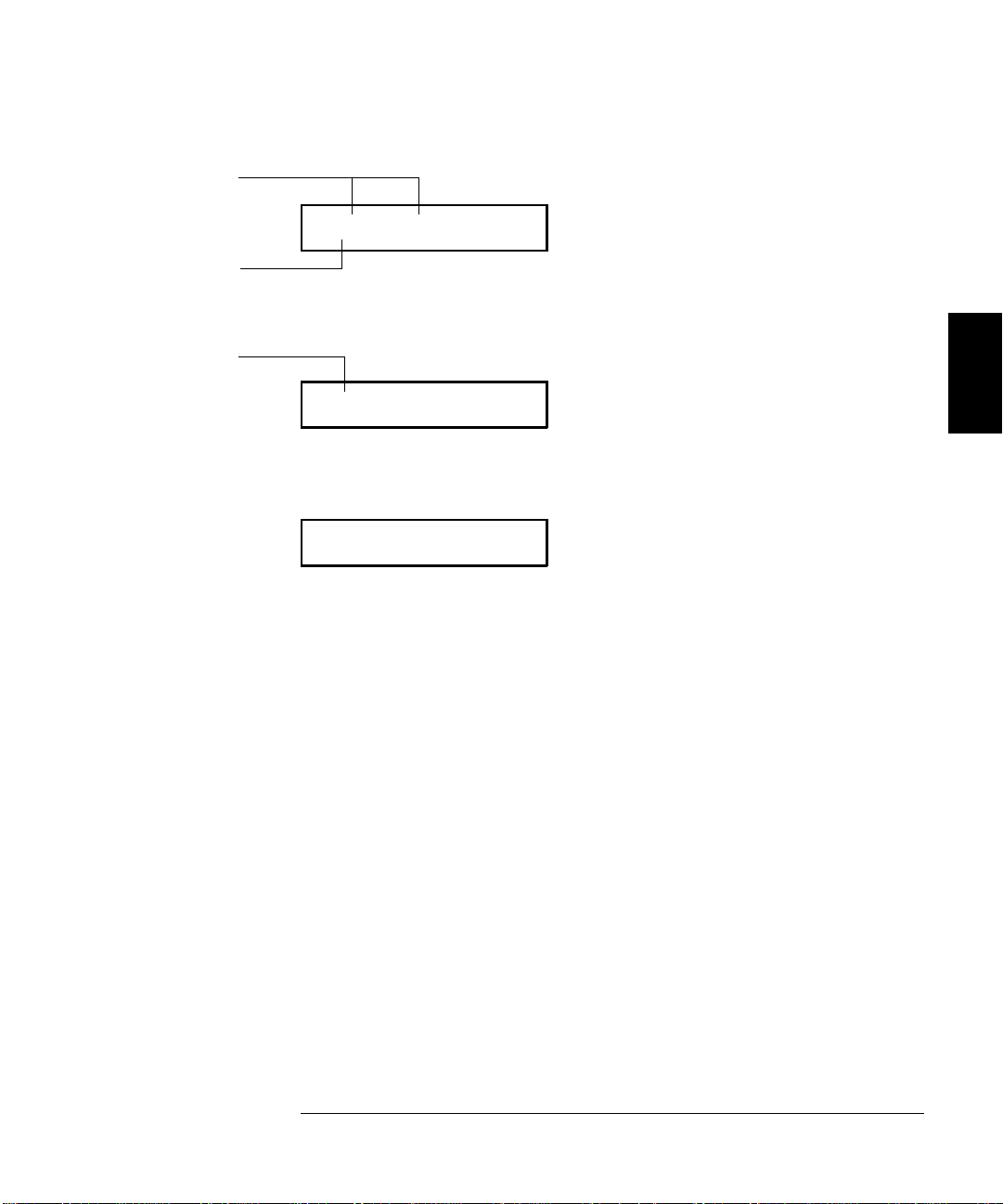
10.216,5 VDC
“1⁄2” digit
“1⁄2” digit
1
⁄
This is the 10 Vdc range, 5
digits are displayed.
2
-045.23 mVDC
This is the 100 mVdc range, 4
1
⁄
digits are displayed.
2
113.325,6 OHM
This is the 100 ohm range, 6
1
⁄
digits are displayed.
2
• The resolutio n is stor ed in volatile memory; the multimeter sets the
resolution to 5
1
⁄
digits (for all functio ns ) w hen pow er has b een off or
2
after a remote interface reset.
• The resolution is fixed at 5
• For dc and resistance measurements, changing the number of digits
1
⁄
digits for continuity and diode tests.
2
does more than just change the resolution of the multimeter. It also
changes the integration time, which is the period the multimeter’s
analog-to-digital (A/D) converter samples the input signal for a
measurement. See also “Integration Time,” on page 57.
• For ac measurements, the resolution is actually fixed at 6
If you select 4
1
⁄
digits or 5
2
1
⁄
digits, the multimeter “masks” one or
2
1
⁄
digits.
2
two digits. The only way to c ontrol th e reading rate for ac measur ements
is by setting a trigger delay (see page 79).
3
• For ratio measurements, the specified resolution applies to the signal
connected to the
Input terminals.
55
Page 58

Chapter 3 Features and Functions
Measurement Configuration
Resolution
(continued)
• Front-Panel Operation: Select either the slow or fast mode for eac h
resolution setting. The default m ode is 5 digits slow.
5: RESOLUTION (MEAS MENU)
See also “To Set the Resolution,” on page 21.
• Remote Interface Operation: You can set the resolution using the
foll owing co m m a nds.
CONFigure:<function> {<range>|MIN|MAX|DEF},{<resolution>|MIN|MAX|DEF}
MEASure:<
<
function>:RESolution {<resolution>|MIN|MAX}
function>? {<range>|MIN|MAX|DEF},{<resolution>|MIN|MAX|DEF}
Specify the resolution in the same units as the measurement
function, not in nu m b er of digi ts. For example, for dc volts , specify the
resolution in volts. For frequency, specify the resolution in hertz.
CONF:VOLT:DC 10,0.001 4
MEAS:CURR:AC? 1,1E-6 6
1
⁄
digits on the 10 Vdc range
2
1
⁄
digits o n th e 1 A ra n g e
2
CONF:FREQ 1 KHZ,0.1 Hz 1000 Hz input, 0.1 Hz resolution
VOLT:AC:RES 0.05 50 mV resolution on the ac fun ction
56
Page 59

Chapter 3 Features and Functions
Measurement Configuration
Integration Time
Integration time is the period during which the multimeter’s analog-todigital (A/D) converter samples the input signal for a measurement.
Integration time affects the measurement resolution (for better resolution,
use a longer integration time), and measurement speed (for faster
measurements, use a shorter integration time).
Applies to all measurement functions except ac voltage, ac current,
frequency, and period. The integration time for the math operations
(null, min-max, dB, dBm, limit test) is the same as the integration time
for the measurement function in use.
• Integration time is specified in number of power line cycles (NPLCs).
The choices are 0.02, 0.2, 1, 10, or 100 power line cycles. The default
is 10 PLCs.
• The integration time is stored in volatile memory; the multimeter
selects 10 PLCs when power has been off or after a remote
interface reset.
3
• Only the integral number of power line cycles (1, 10, or 100 PLCs)
provide normal mode (line frequency noise) rejection.
• The only way to contr ol th e reading rate for ac measu r em en ts is by
setting a trigger delay (see page 79).
• The following table shows the relationship between integration time
and measurement resolution.
Integration Time
0.02 NPLC
0.2 NPLC
1 NPLC
10 NPLC
100 NPLC
Resolution
0.0001 x Full-Scale
0.0000 1 x Full-Scale
0.000003 x Full-Scale
0.000001 x Full-Scale
0.0000 00 3 x F ull -S ca le
57
Page 60

Chapter 3 Features and Functions
Measurement Configuration
Integration Time
(continued)
• Front-Panel Operation: Integration time is set indirectly when you
select the numbe r o f d i gi t s. See the table for resolution on page 54.
• Remote Interface Operation:
<function>:NPLCycles {0.02|0.2|1|10|100|MINimum|MAXimum}
For frequen cy an d per iod m eas urem e nts , aperture time (or gate time)
1
⁄
is analogous to integration time. Specify 10 ms (4
(default; 5
1
⁄
digits), or 1 second (6
2
1
⁄
digits).
2
digits), 100 ms
2
FREQuency:APERture {0.01|0.1|1|MINimum|MAXimum}
PERiod:APERture {0.01|0.1|1|MINimum|MAXimum}
Front / Rear Input Terminal Switching
Any measurement made using the front terminals can also be made
using the input terminals on the rear panel. See “The Front Panel at
a Glance,” on page 2, for the locati on of the front / rear switch.
The input terminals can only b e configured fro m the front panel.
You cannot select the terminals from the remote interface, but you
can query the present setting.
• The Rear annunciator turns on when you select the rear terminals.
• Remote Interface Operation: You can query the multimeter to
determine whether the front or rear input terminals are selected.
ROUTe:TERMinals? returns “FRON” or “REAR”
58
Page 61

Chapter 3 Features and Functions
Measurement Configuration
Autozero
When autozero is enabled (default), the multimeter internally
disconnects the input signal following each measurement, and takes a
zero reading. It then subtract s the zer o re a din g from the preceding
reading. This prevents offset voltages present on the multimeter’s input
circuitry from affecting measurement accuracy.
When autozero is disabled, the multimeter takes one zero re ad in g an d
subtracts it from all subsequent measurements. It takes a new zero
reading each time you change the function, range, or integration time.
Applies to dc voltage, dc current, and 2-wire ohms measurements only.
Autozero i s e na b led when you select 4-wire ohms or ratio me asurements.
• The autozero mode i s stor ed in volatile memory; the multimeter
automatically enables autozero when power has been off or after a
remote interface reset.
• Front-Panel Operation: The autozero mode is set indirectly when you
set the resolution.
Resolution Choices
Fast 4 Digit
* Slow 4 Digit
Fast 5 Digit
* Slow 5 Digit (default)
*
Fast 6 Digit
Slow 6 Digit
* These settings configure the multimeter just as if you had
pressed the corresponding “DIGITS” keys from the front panel.
• Remote Interface Operation: The OFF and ONCE parameters have a
similar effe ct . Autozero
Autozero
ONCE issues an immediate zero measurement.
Integration Time
0.02 PLC
1 PLC
0.2 PLC
10 PLC
10 PLC
100 PLC
Autozero
Off
On
Off
On
On
On
OFF does not issue a new zero measurement.
3
ZERO:AUTO {OFF|ONCE|ON}
59
Page 62

Chapter 3 Features and Functions
Measurement Configuration
Autozero
(continued)
The following table shows the relationship between integration time and
autozero settings from the remote interface and the corresponding
front-panel settings.
From 34401A Specifications:
Remote Configuration
NPLC: 100
Autozero: On
Digits Displayed: 6
1
⁄
2
NPLC: 100
Autozero: Off
Digits Displayed: 6
1
⁄
2
NPLC: 10
Autozero: On
Digits Displayed: 6
1
⁄
2
NPLC: 10
Autozero: Off
Digits Displayed: 6
1
⁄
2
NPLC: 1
Autozero: On
Digits Displayed: 5
1
⁄
2
NPLC: 1
Autozero: Off
Digits Displayed: 5
1
⁄
2
NPLC: 0.2
Autozero: On
Digits Displayed: 5
1
⁄
2
NPLC: 0.2
Autozero: Off
Digits Displayed: 5
1
⁄
2
NPLC: 0.02
Autozero: On
Digits Displayed: 4
1
⁄
2
NPLC: 0.02
Autozero: Off
Digits Displayed: 4
1
⁄
2
Front-Panel Equivalent
Slow 6 digits
N/A
Fast 6 digits
Slow 5 digits
N/A
Slow 4 digits
N/A
N/A
Fast 5 digits
N/A
Fast 4 digits
Digits Displayed
N/A
1
⁄
6
2
N/A
1
⁄
6
2
N/A
1
⁄
5
2
N/A
1
⁄
5
2
N/A
1
⁄
4
2
Readings/Sec
N/A
0.6
N/A
6
N/A
60
N/A
300
N/A
1000
1
1
See the Agilent 34401A specifications listed on page 217.
60
Page 63
Chapter 3 Features and Functions
Measurement Configuration
Ranging
You can let the multimeter automatically select the range using
autoranging or you can select a fi xed range using manual ra nging.
Autoranging is convenient because the multimeter automatically selects
the appropriate range for each measurement. However, you can use
manual ranging for faster measurements since the multimeter does not
have to determine which range to use for each measurement.
• The selected mode (a u to or manu a l ran ge ) is store d in volatile
memory; the multimeter returns to autoranging when power has
been off or after a remote interface reset.
• Autorange t h re sholds:
Down range at <10% of range
Up range at >120% of range
• If the input signal is greater than the present range can measure, the
multimeter gives a n overload indication: “
or “9.90000000E+37” from the remote interface.
• For frequen cy and period measuremen t s, th e mult im eter uses one
“range” for all inputs between 3 Hz and 300 kHz. The multimeter
determines an internal resolution based on a 3 Hz signal. If you
query the range, the multimeter will respond with “3 Hz”. With no
input signal applied, frequency and period measurements return “0”.
OVLD” from the front panel
3
• The range is fixed for continuity tests (1 kΩ range) and diode tests
(1 Vdc range with 1 mA current source output).
• For ratio measurements, the specified range applies to the signal
connected to the
selected for reference voltage measurements on the
Input terminals. Autoranging is automatically
Sens e terminals.
Ranging is local to the selected function. This means that you can select
the ranging method (auto or manual) for each function independently.
When manually ranging, the selected range is local to the function; the
multimeter rem em b ers the range when you switch between functions.
61
Page 64

Chapter 3 Features and Functions
Measurement Configuration
Ranging
(continued)
• Front-Panel Operation: Use the front-panel RANGE keys to select
autoranging or manual ranging. For frequency and period
measurements from the front panel, ranging applies to the signal’s
input voltage, not its frequency.
See also “To Select a Range,” on page 20.
• Remote Interface Operation: You can se t the range using any of the
foll owing co m m a nds.
CONFigure:<
MEASure:<
<
function>:RANGe {<range>|MINimum|MAXimum}
<
function>:RANGe:AUTO {OFF|ON}
function> {<range>|MIN|MAX|DEF},{<resolution>|MIN|MAX|DEF}
function>? {<range>|MIN|MAX|DEF},{<resolution>|MIN|MAX|DEF}
62
Page 65
Chapter 3 Features and Functions
Math Operations
Math Operations
There are five mat h oper a tion s av ai la ble, on ly one of w hich can be
enabled at a time. Each math operation performs a mathematical
operation on ea ch re a din g or stor es dat a on a series of re adi n gs.
The selected math operation remains in effect until you disable it,
change functions, turn off the power, or perform a remote interface
reset. The math ope rat ions use one or more inter nal reg i ste rs. You can
preset the values in some of the registers, while others hold the results
of the math operat ion .
Null
Min -Max
dB
dBm
Limit
The following table shows the math/measurement function combinations
allowed. Each “
X” indicates an allowable combination. If you choose a
math operation that is not allowed with the present measurement
function, math is turned off. If you select a valid math operation and
then change to one that is invalid, a “Settings conflict” error is generated
from the remote interface.
DC V
X
X
X
X
X
AC V
X
X
X
X
X
DC I
X
X
X
AC I
X
X
X
Ω
X
X
X
2W
Ω
X
X
X
4W
Freq
X
X
X
Per
Con t Dio d e Ratio
X
X
X
From the front pan el , you enabl e a math oper at ion by pr ess ing t he
appropriate key. The exception is Limit Test which you enable using the
LIMIT TEST command in the MATH MENU.
From the remote interface, the math operations and registers are
controlled using commands within the
CALCulate command
subsystem. First, select the math operation you want to use (the default
function is null):
CALCulate:FUNCtion {NULL|DB|DBM|AVERage|LIMit}
3
X
X
Then, enable the selected math function by turning the math state on:
CALCulate:STATe ON
63
Page 66

Chapter 3 Features and Functions
Math Operations
Min–Max Operation
The min-max operation stores the minimum and maximum readings
during a series of measurements. The multimeter then calculates the
average of all readings and records the number of readings taken since
min-max was enabled.
Applies to all measurement functions, except continuity and diode.
• After you enable min-max, the first reading that the multimeter
takes is stored as both the minimum and maximum value.
The minimum is replaced with any subsequent value that is less.
The maximum is replaced with any subsequent value that is greater.
• The multimeter displays “MIN” or “MAX” and beeps (if the front-pan el
beeper is enabled) whenever a new minimum or maximum is found.
It is possible that the multimeter will beep even if the displayed
reading does not change; this is because the multimeter’s internal
resolution may be greater than the displayed resolution. See also
“Beeper Control,” on page 88.
• The minimum, maximum, average, and count are stored in volatile
memory; the multimeter clears the valu es when m in-ma x is t urned on,
when power has been off, or after a remote interface reset.
• Front-Panel Operation: After enabling min-max, you can read the
stored minimum, maximum, average, and count by pressing
Shift > (Menu Recall). Turning on the menu does not disa b l e
the min-max operation; the multimeter will resume taking
measurements when you turn off the menu.
1: MIN-MAX (MATH MENU)
See also “To Store Minim um and Maximum Reading s,” on page 39.
64
Page 67

Chapter 3 Features and Functions
Math Operations
• Remote Interface Operation: You can use the following commands to
make min-max measurements.
CALCulate:FUNCtion AVERage
CALCulate:STATe {OFF|ON}
CALCulate:AVERage:MINimum?
CALCulate:AVERage:MAXimum? read the maximum value
CALCulate:AVERage:AVERage? read the average of all readings
CALCulate:AVERage:COUNt? read the count
read the minimum value
A new command is available starting with firmware Revision 2 which
allows you to take readings using
internal memory. This command may be useful with the min-max
operation since it all ows you to deter mine the averag e of a series of
readings wit hout storing the individual values.
DATA:FEED RDG_STORE, "" do not store readings
DATA:FEED RDG_STORE, "CALCulate" store readings (default)
See page 126 for more information on using the
INITiate without storing them in
DATA:FEED command.
Null (Relative) Operation
When making null measurements, also called relative, each reading
is the difference b etw een a stor ed n ull va lue and the inpu t sig n al.
One possible application is in making more accurate two-wire ohms
measurements by nulling the test lead resistance.
Result = reading – null value
Applies to al l measurement fun ctions, excep t co ntinuity, di ode, and ratio.
• The null value is adjustable and you can set it to any value between
0 and
±120% of the highest range, for the present function.
3
• The null value is stored in volatile memory; the value is cleared
when power has been off, after a remote interface reset, or after a
function change.
65
Page 68

Chapter 3 Features and Functions
Math Operations
Null (Relative)
(continued)
• The null value is stored in the m ultim e t er ’s Nu ll Regis ter . Ther e a re
two ways you can specify the null value. First, you can enter a
specific num ber into the register from the fr on t-pa n el m en u or fr om
the remote interface. Any previously stored value is replaced with the
new value. If you are operating the multimeter from the front panel,
entering a nul l va lue also turns on the null functio n.
The second way to enter the null value is to let the multimeter store
the first reading in the register. After you enable null, the first
reading displayed will be zero (if you have not changed the value
stored in the register). If you entered a number into the register, as
described in the paragraph above, the first reading does not overwrite
the stored valu e.
• Front-Panel Operation: After enabling null, you can edit the stored
null value by pressing
Shift > (Menu Recall). Any previously
stored value is replaced with the new value. Turning on the menu
does not disable the null operation; the multimeter will resume
taking measurements when you turn off the menu.
2: NULL VALUE (MATH MENU)
See also “To Make Null (Rel ative) Measurements,” on page 38.
• Remote Interface Operation: You can use the following commands to
make null measurements. Math must be enabled before you can store
a value in the Nu ll Re g is ter .
CALCulate:FUNCtion NULL
CALCulate:STATe {OFF|ON}
CALCulate:NULL:OFFSet {<
value>|MINimum|MAXimum}
The following pro gra m se gme nt sho ws t he prop er orde r tha t you
should execute the commands to enable null and set an offset value.
CALC:FUNC NULL
CALC:STAT ON
CALC:NULL:OFFS -2.0
66
Page 69

Chapter 3 Features and Functions
Math Operations
dB Measurements
Each dB measurement is the difference between the input signal and a
stored relative value, with both values converted to dBm.
dB = readi ng in dBm – relative value in dBm
Applies to dc volta ge an d ac voltag e meas u reme n ts onl y.
• The relative value is adjustable and you can set it to any value
between 0 dBm and
±200.00 dBm.
• The relative value is stored in volatile memory; the value is cleared
when power has been off, after a remote interface reset, or after a
function change.
• The relative value is stored in the multimeter’s dB Relative Register.
There are two w ays yo u ca n spec i fy the r el at iv e valu e. First , you can
enter a specific nu mb er into the re gis ter fr om the fr on t -pan el men u or
from the remote interface. Any previously stored value is replaced
with the new value. If you are operating the multimeter from the front
panel, entering a relative va lue also turns on the dB function.
The second way to enter the relative value is to let the multimeter
take the first reading, convert it to dBm, and store that value in the
register. Changing the dBm reference resistance (see page 68) does
not change the s t ored re l at ive valu e. Aft er you ena b le dB, the first
readin g ta k en will be 0 dB (if you have not chan g ed th e valu e sto re d in
the register). If you entered a number into the register, as described in the
paragraph above, the first reading does not overwrite t he store d va lu e.
• Front-Panel Operation: After enabling dB, you can edit the stored
rela tive valu e b y pressing
Shift > (Menu Recall). Any prev iously
stored value is replaced with the new value. Turning on the menu
does not disable the dB operation; the multimeter will resume
taking measurements when you turn off the menu.
3: dB REL (MATH MENU)
3
See also “To Make dB Measurements,” on page 40.
67
Page 70

Chapter 3 Features and Functions
Math Operations
• Remote Interface Operation: You can use the following commands to
make dB measurements. Math must be enabled b efore you can store a
value to the Relative Register.
CALCulate:FUNCtion DB
CALCulate:STATe {OFF|ON}
CALCulate:DB:REFerence {<
value>|MINimum|MAXimum}
dBm Measurements
The dBm operation calculates the power delivered to a resistance
referenced to 1 milliwatt.
dBm = 10
× Log
( reading2 / reference resistance / 1 mW )
10
Applies to dc volta ge an d ac voltag e meas u reme n ts onl y.
• You can choose from 17 different reference resistance values.
The factory setting for the referenc e resi st a nce is 600
Ω.
The choice s are: 50, 75, 93, 110, 124, 125, 135, 150, 250, 300, 500,
600, 800, 900, 1000, 1200, or 8000 ohms.
• The reference resistance is stored in non-volatile memory, and does not
change when power has been off or after a remote interface reset.
• Front-Panel Operation: After enabling dBm, you can select a new
reference resistance by pressing
Shift > (Menu Recall). Turning
on the menu does not disable the dBm operation; the multimeter
will resume taking measurements when you turn off the menu.
4: dBm REF R (MATH MENU)
See also “To Make dBm Measurem ents,” on page 41.
• Remote Interface Operation: You can use the following commands to
make dBm measurements.
CALCulate:FUNCtion DBM
CALCulate:STATe {OFF|ON}
CALCulate:DBM:REFerence {<
value>|MINimum|MAXimum}
68
Page 71

Chapter 3 Features and Functions
Math Operations
Limit Testing
The limit test operation enables you to perform pass/fail testing to
upper and lower limits that you specify.
Applies to all measurement functions, except continuity and diode tests.
• You can set the upper and lower limits to any value between 0 and
±120% of the highest range, for the present function. The upper limit
selected should always be a more positive number than the lower
limit. The default upp er and lower limits are both “0”.
• The upper and lower limits are stored in volatile memory; the
multimeter sets both limits to “0” when power has been off, after a
remote interface reset, or after a function change.
• You can configure the multimeter to generate a service request (SRQ)
on the first occurrence of a failed reading. See “The SCPI Status
Model,” starting on page 134 for more information.
• Front-Panel Operation: The multimeter displays “OK” for each
reading that is within the specified limits. It displays “
HI” or “ LO” for
each reading that exceeds the upper or lower limit. The multimeter
beeps once (if the front-panel beeper is enabled) on the first
occurrence of a failed reading after a good reading. See also “Beeper
Control,” on page 88.
5: LIMIT TEST (MATH MENU) enable or disab le limit test
6: HIGH LIMIT (MATH MENU) set the upper limit
7: LOW LIMIT (MATH MENU) set the lower limit
You can also turn off limit test by selecting a diffe rent math operatio n
from the front pane l (only one m ath oper ation can b e enab led at a tim e ).
3
69
Page 72
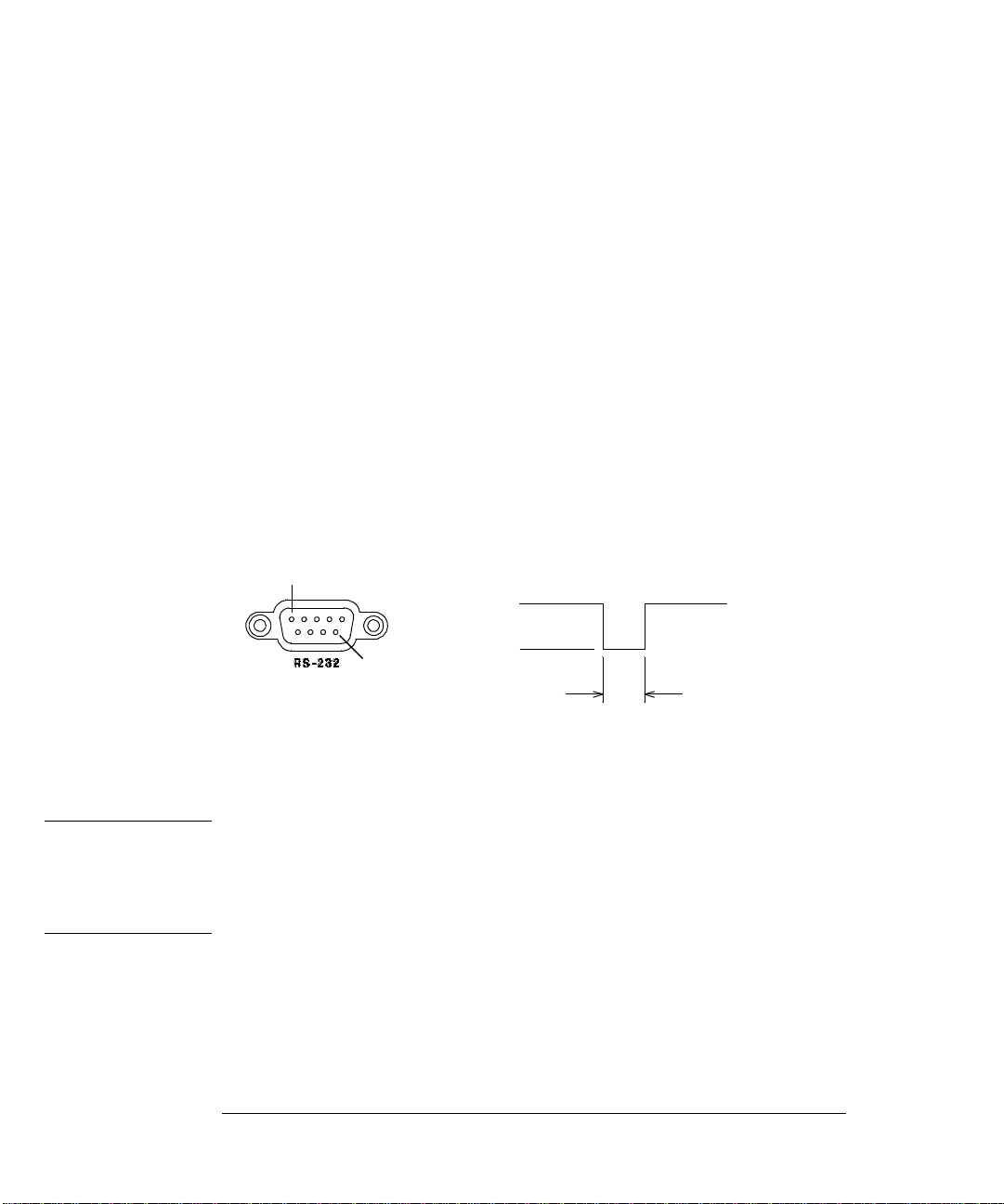
Chapter 3 Features and Functions
Math Operations
Limit Testing
(continued)
• Remote Interface Operation: You can use th e f oll owing comman ds for
limit testing.
CALCulate:FUNCtion LIMit
CALCulate:STATe {OFF|ON}
CALCulate:LIMit:LOWer {<
CALCulate:LIMit:UPPer {<
• There are two unu s ed pin s on the RS-232 interface co nnec t or whi c h
value>|MINimum|MAXimum}
value>|MINimum|MAXimum}
are available to indicate the pass/fail status of readings taken with
limit testing. To configure these pins for limit testing, you must
install two jumpers inside the multimeter. See the Service Guide for
more informa tion.
A low-going pulse is output to pin 1 for each reading that is within
the specified limits. A low-going pulse is output to pin 9 for each
reading that exceeds the upper or lower limit.
1
5 V
9
0 V
Pin 1: Pass Output
Pin 9: Fail Output
2 ms
minimum
Caution Do not use the RS-232 interface if you have configured the multimeter to
output pass/fail signals on pins 1 and 9. Internal components on the
RS-232 interface circuitry may be damaged.
70
Page 73

Chapter 3 Features and Functions
Triggering
Triggering
The multimeter’s triggering system allows you to generate triggers
either manually or automatically, take multiple readings per trigger,
and insert a delay before each reading. Normally, the multimeter will
take one reading each time it receives a trigger, but you can specify
multiple readings (up to 50,000) per trigger.
You can trigger the multimeter from the front panel using a single
trigger, an external trigger, or auto triggering. Single triggering
takes one reading each time you press the
triggering is like single triggering, but the multimeter waits for a
pulse on the rear-panel Ext Trig (external trigger) terminal before
taking a readi ng. Auto triggeri ng t a ke s continuous readi ngs at the
fastest rate possible for the present configu ration. Se e also “To Trigger
the Multimeter,” on page 42.
Triggering the multimeter from the remote interface is a multi-step
process that offers triggering flexibility.
Single key. External
3
• First, you must configure the multimeter for the measurement by
selecting the function, range, resolution, etc.
• Then, you must specify the source from which the multimeter will
accept the trigger. The multimeter will accept a software (bus) trigger
from the remote interface, a hardware trigger from the Ext Trig
terminal, or an immediate internal trigger.
• Then, you must make sure that the multimeter is ready to accept a
trigger from the specified trigger source (this is called the
wait-for-trigger st ate) .
The diagram on the next page shows the multimeter’s triggering system.
71
Page 74
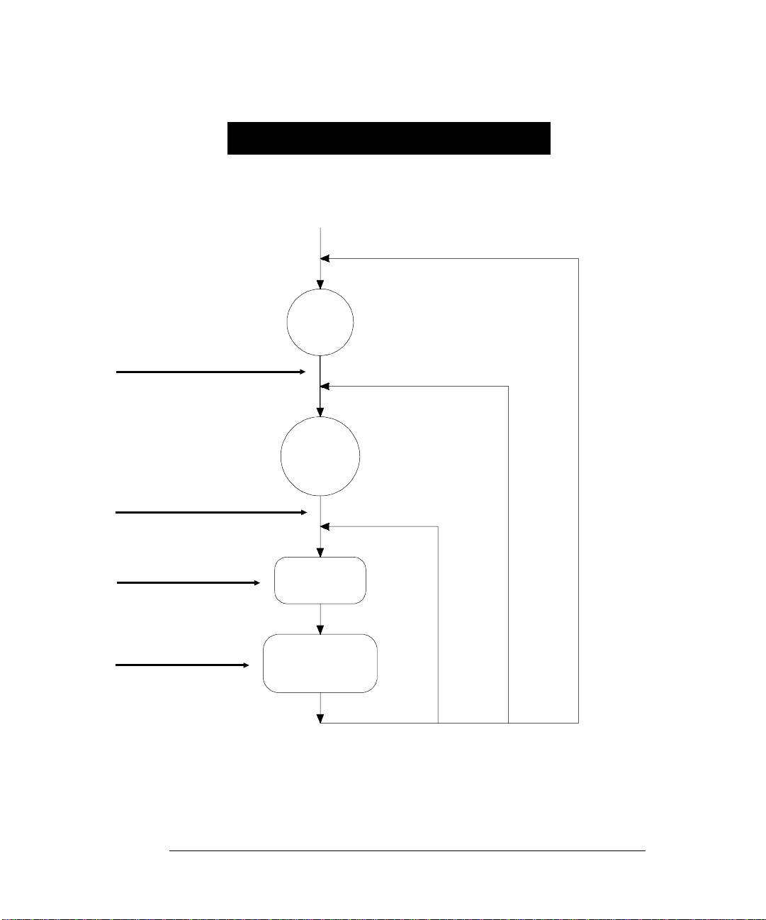
Chapter 3 Features and Functions
Triggering
Agilent 34401A Trigg ering System
Initiate Triggering
MEASure?
READ?
INITiate
Trigger Source
TRIGger:SOURce IMMediate
TRIGger:SOURce EXTernal
TRIGger:SOURce BUS
Front-panel “Single” key
Idle
State
Wait-for Trigger
State
Trigger Delay
TRIGger:DELay
Sample ( ∗ )
Annunciator
72
Delay
Measurement
Sample
Sample
Count
≠ 1
Trigger
Count ≠ 1
Page 75

Chapter 3 Features and Functions
Triggering
Trigger Source Choices
You must specify the source from which the multimeter will accept a
trigger. From the front panel, the multimeter will accept a single
trigger, a ha rd wa re trigger from the Ext Trig terminal, or continuously
take readings using auto trigger. At power-on, auto triggering is used.
From the remote interface, the multimeter will accept a software (bus)
trigger, a ha rd wa re trigger from the Ext Trig terminal, or an immediate
internal trigger. The
measurement.
Q (sample) annunciator turns on during each
• The trigger so urce is stored in volatile memory; the source is set to
auto trigger (front panel) or immediate (remote interface) when
power has been off or after a remote interface reset.
• To select the trigger source from the remote interface, use the
foll owing co m m a nd. The
automatically set the trigger source to
TRIGger:SOURce {BUS|IMMediate|EXTernal}
Auto Triggering In the auto trigger mode (front panel only), the
multimeter continuously takes readings at the fastest rate possible
for the present configuration. This is the power-on trigger source for
front-panel operation.
Single Triggering In the single trigger mode (front panel only),
you can manually trigger the multimeter by pressing
The multimet er tak es one r eadi n g, or the spec i fied n umber of
readings (sam ple c ou nt) , eac h tim e yo u pres s the key . The
annunciator turns on when the multimeter is waiting for a trigger.
The front-panel
Single key is disabled when in remote.
CONFigure and MEASure? commands
IMMediate.
Single .
Tri g
3
73
Page 76

Chapter 3 Features and Functions
Triggering
External Triggering In the external trigger mode, the multimeter
will accept a hardware trigger applied to the Ext Trig terminal.
The multimet er tak es one r eadi n g, or the spec i fied n umber of readings
(sample count), each time Ext Trig receives a low-true pulse.
See also “External Tri gger Terminal,” on page 83.
• The multimeter buffers one external trigger. This means that if the
multimeter is taking a reading and another external trigger occurs,
that trigger is a ccepted (a “Trigger ignored ” error is not reported).
After the reading in progress is complete, the stored trigger satisfies
the trigger source and then the trigger is issued.
• Front-Panel Operation: The external trigger mode is like the single
trigger mode except that you apply the trigger to the Ext Trig
terminal. Pressing
enables the external trigger mode. The
Single to enable the single trigger mode also
Tri g annunciator turns on
when the multimeter is waiting for an external trigger.
The front-p an el
• Remote Interface Operation:
Single key is disabled when in remote.
TRIGger:SOURce EXTernal
74
Page 77

Chapter 3 Features and Functions
Triggering
Internal Tr igg ering In the internal trigger mode (r em ote interface only),
the trigger signal is always present. When you place the multimeter in
the wait-for-trigger state, the trigger is issued immediately. This is the
power-on trigger source for remote interface operation.
To select the internal trigger source, send the following command.
CONFigure and MEASure? commands automatically set the
The
trigger source to
IMMediate.
TRIGger:SOURce IMMediate
Software (Bus) Triggering The bus trigger mode is available only
from the remote interface. This mode is similar to the single trigger
mode from the front panel, but you trigger the multimeter by sending
a bus trigger command.
• To select the bus trigger source, send the following command.
TRIGger:SOURce BUS
• To trigger the multimeter from the r emote in terface (GPIB or RS-232),
send the
*TRG (trigger) com ma n d. The *TRG command will not be
accepted unless the multimeter is in the wait-for-trigger state.
• You can also trigger the multimeter from the GPIB interface by
sending the
IEEE-488 Group Execute Trigger (GET) message.
The multimeter must be in the wait-for-trigger state. The following
statement shows how to sen d a
GET using BASIC.
TRIGGER 722 Group Execute Trigger
3
75
Page 78
Chapter 3 Features and Functions
Triggering
The Wait-for-Trigger State
After you have configured the multimeter and selected a trigger source,
you must place the multimeter in the wait-for-trigger state. A trigger
will not be accepted until the multimeter is in this state. If a trigger
signal is present, and if multimeter is in the “wait-for-trigger” state,
the measurement sequence begins and readings are taken.
The “wait-for-t rigger” state is a term used prima rily for remote interface
operation. From the front panel, the multimeter is always in the
“wa it-for- trigger ” state and will accep t trig g er s at an y time , u nl ess a
measurement is already in progress.
You can place the multimeter in the “wait-for-trigger” state by executing
any of the following commands from the remote interface.
MEASure?
READ?
INITiate
The multim eter re qui res approximately 20 ms of set-up time after you
send a comm a nd to change to the “wait-for-trigger” state. Any triggers
that occur during this set-up time are ignored.
Halting a Measurement in Progress
You can send a device clear at any time to halt a measurement in
progress and place the multimeter in the “idle state.” The following
statement shows how to send a device clear over the
using BASIC.
CLEAR 722 IEEE-488 Device Clear
A device clear does not affect the configuration of the triggering system.
The trigger source, sample count, trigger delay, and number of triggers
are not changed.
76
GPIB interface
Page 79

Chapter 3 Features and Functions
Triggering
Number of Samples
Normally, the multimeter takes one reading (or sample) each time it
receives a tr i gger from the selected trigger source (if t he multimeter is
in the wait-for-trigger state). You can, however, instruct the multimeter
to take multiple readings for each trigger received.
• Number of samples: 1 to 50,000. The default is 1 sample p er tr ig g er .
• The selected num ber of samples is stored in volatile memory; the
multimeter sets the sample count to 1 when power has been off or
after a remote interface reset. The
commands automatically set the sample count to 1.
• Front-Panel Operation:
3: N SAMPLES (TRIG MENU)
• Remote Interface Operation:
SAMPle:COUNt {<value>|MINimum|MAXimum}
CONFigure and MEASure?
3
77
Page 80

Chapter 3 Features and Functions
Triggering
Number of Triggers
Normally, the multimeter will accept only one trigger before returning
to the “idle” trigger state. You can, however, instruct the multimeter to
accept multiple triggers.
This feature is available only from the remote interface. If you set the
trigger c ou nt and th e n go to loc al (fr on t panel), the mult ime te r ign or e s
the trigg er count setting; when you return to remote, the trigger count
returns to the va lue you selected.
• Number of triggers: 1 to 50,000. The defa ul t is 1 tr ig g er.
• The selected num ber of t rigg er s is stored in volatile memory; the
multimeter sets the trigger count to 1 when power has been off or
after a remote interface reset. The
commands automatically set the trigger count to 1.
• Remote Interface Operation:
TRIGger:COUNt {<value>|MINimum|MAXimum|INFinite}
CONFigure and MEASure?
78
Page 81

Chapter 3 Features and Functions
Triggering
Trigger Delay
You can insert a delay between the trigger signal and each sample that
follows. This may be useful in applications where you want to allow the
input to settle before taking a reading, or for pacing a burst of readings.
If you do not specify a trigger delay, the multimeter automatically
selects a delay for you.
• Delay range: 0 to 3600 seconds. The default trigger delay is
automatic; the d elay is det er mined b y fu nc tion, ran ge , inte gr ation time,
and ac filter setting (see also “Automatic Trigger Delays,” on page 81).
• The trigger delay is stored in volatile memory; the multimeter selects
an automatic trigger delay when power has been off or after a remote
interface reset. The
CONFigure and MEASure? commands
automatically set the trigger delay to automatic.
• If you specify a delay other than automatic, that same delay is used
for all functions and ranges.
• If you have configured the multimeter to take more than one reading
per trigger (sample count > 1), the specified trigger delay is inserted
between the trigger and each reading.
• Front-Panel Operation: You can use an automatic trigger delay or
you can specify a delay in seconds.
2: TRIG DELAY (TRIG MENU)
If an automatic trigger delay is enabled, “AUTO” is displayed
momentarily before the actual number of seconds is displayed.
--- AUTO ---
3
79
Page 82

Chapter 3 Features and Functions
Triggering
Trigger Dela y
(continued)
• Front-Panel Operation (continued)
To set the delay to 0 seconds, select the “parameter” level of the
DELAY
the right side of the display. Press
command. Move the flashing cursor to the “units” location on
∨ until ZERO DELAY is reached,
then press Menu Enter.
ZERO DELAY
To select the automatic trigger delay, select the “parameter” level
of the
TRIG DELAY command. Move the flashing cursor to the
“units” location on the right side of the display. Press
AUTO DELAY is reached, th en press Menu Enter.
∨ until
AUTO DELAY
• Remote Interface Operation:
You can use the following command to set the trigger delay.
TRIGger:DELay {<seconds>|MINimum|MAXimum}
You can use the following command to set an automatic trigger delay.
TRIG
TRIGger:DELay:AUTO {OFF|ON}
80
Page 83

Chapter 3 Features and Functions
Triggering
Automatic Trigger Delays
If you do not specify a trigger delay, the multimeter selects an
automatic delay for you. The delay is determined by function, range,
integration time, and ac filter setting.
• DC Voltage and DC Cu rrent (for all ranges ):
Integration Time
NPLC ≥ 1
NPLC < 1
• Resistance (2-wire and 4-wire):
Rang e
100 Ω
1 kΩ
10 kΩ
100 kΩ
1 MΩ
10 MΩ
100 MΩ
• AC Voltage and AC Cu rrent (for all ranges) :
Remote or single/external trigger
AC F ilter
Slow
Medium
Fast
Trigger Delay
1.5 ms
1.0 ms
Trigger Delay
(For NPLC ≥ 1)
1.5 ms
1.5 ms
1.5 ms
1.5 ms
15 ms
100 ms
100 ms
Trigger Delay
7.0 sec
1.0 sec
600 ms
Range
100 Ω
1 kΩ
10 kΩ
100 kΩ
1 MΩ
10 MΩ
100 MΩ
Front panel with auto tr igger ON
AC Filter
Slow
Medium
Fast
3
Trigger Delay
(For NPLC < 1)
1.0 ms
1.0 ms
1.0 ms
1.0 ms
10 ms
100 ms
100 ms
Trigger Delay
1.5 sec
200 ms
100 ms
• Frequenc y and Pe ri od :
Remote or single/external trigger
Trigger Delay
1.0 sec
Front panel with auto trigger ON
Trigger Delay
0 sec
81
Page 84

Chapter 3 Features and Functions
Triggering
Reading Hold
The reading hold feature allows you to capture and hold a stable
reading on the front-panel display. This is especially useful in situations
where you want to take a reading, remove the test probes, and have the
reading remain on the display. When a stable reading is detected, the
multimeter emits a beep (if the front-panel beeper is enabled) and holds
the reading on the display. See also “Beeper Control,” on page 88.
The reading hold feature is available only from the front panel. If you go
to remote when reading hold is enabled, the multimeter ignores it; when
you return to loc al (fr on t panel), reading hold is enable d aga in .
• Reading hold has an adjustable sen s iti vit y b an d (adj u st ab le only fr om
the front panel) to allow you to select which readings are considered
stable enough to be displa yed. The band is expressed as a perc en t of
reading, on the selected range. The multimeter will capture and display
a new value only after three consecutive readings are within t he band.
Select one of these values: 0. 01%, 0.10% (default), 1.00%, or 10.00%
of reading. For example, assume that the 1.00% band is selected and
a 5 volt signal is applied to the multimeter. If three consecutive
readings are between 4.975 volts and 5.025 volts, the display will show
a new reading.
• The sensitivity band is stored in volatile memory; the multimeter sets
the band to 0.10% when power has been off or after an interface reset.
• If the multimeter is in autorange when you enable reading hold,
it will autorange to the correct range. If the multimeter is in the
manual r a ng e m o de , th e s am e f ixed range w i ll b e u se d for rea din g hold.
• When reading hold is enabled, the input resistance is automatically
set to 10 M
Ω (AUTO OFF) for all dc voltage ranges. This helps to
minimize noise pickup when the test leads are open-circuit.
• For certain applications, it may be useful to use reading hold with
reading memory. See also “Reading Memory,” on page 84.
• Front-Panel Operation: After enabling reading hold, you can select a
different sensitivity band by pressing
Shift > (Menu Recall).
1: READ HOLD (TRIG MENU)
See also “To Use Reading Hold,” on page 43.
82
Page 85
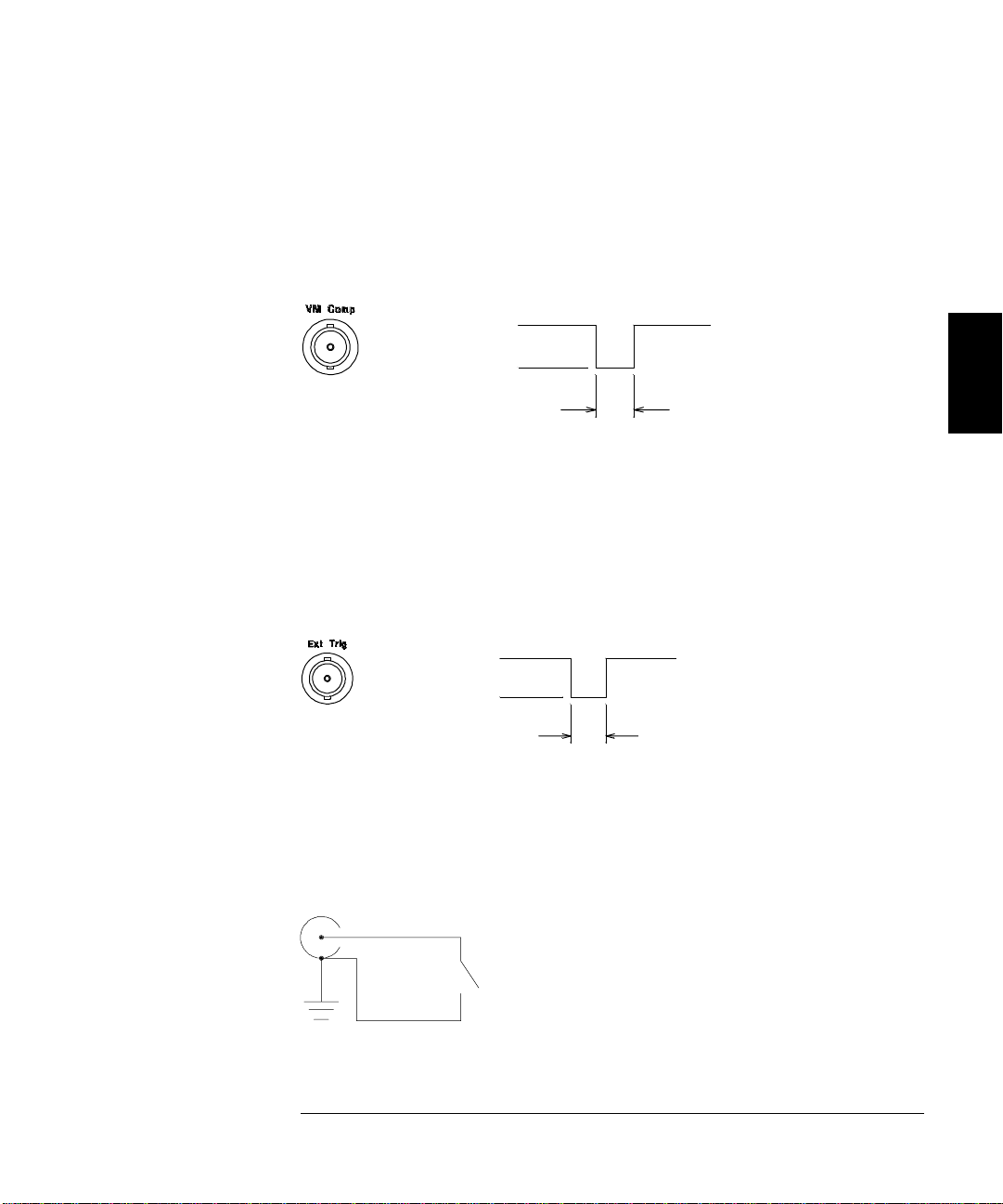
Chapter 3 Features and Functions
Triggering
Voltmeter Complete Terminal
The rear-pan el VM Comp (voltmeter complete) terminal provides a
low-true pulse after the completion of each measurement. Voltmeter
complete and external trigger (see below) implement a standard hardware
handshake sequence between measur ement and s witching devices.
5 V
0 V
Output
Approximately
2 µs
External Trigger Terminal
You can trigger the multimeter by applying a low-true pulse to the
rear-panel Ext Trig (external trigger) terminal. To use this terminal
from the remote interface, you must select the external trigger source
TRIGger:SOURce EXTernal).
(
5 V
0 V
You can use a simple switch to generate an external trigger using the
Ext Trig input as shown below.
Input
>1 µs
3
Ext Trig
83
Page 86

Chapter 3 Features and Functions
System-Related Operations
System-Related Operations
This sectio n gi ve s information on topics such as reading memo ry, errors,
self-test, and front-panel display control. This information is not directly
related to making measurements but is an important part of operating
the multimeter.
Reading Memory
The multimeter can store up to 512 readings in internal memory.
Readings are stored in first-in-first-out (
returned is the first reading stored. The reading memory feature is
available only from the front panel.
• You can use reading memory with all functions, math operations, and
also reading hold. After you have enabled reading memory, you can
change the function. Be aware, however, that the function labels
VDC, OHM, etc. ) are not stored with the reading.
(
FIFO) order. The first reading
• Readings taken while reading memory is enabled are stored in
volatile memory; the multimeter clears the stored readings when
reading memory is turned on again, when power has been off, after a
self-test, or after a remote interface reset.
• You can use reading memory with auto trigger, single trigger,
external trigger, and reading hold. If you configure the multimeter for
multiple readings per trigger, the specified number of readings are
stored in memory each time a trigger is received.
• Front-Panel Operation:
1: RDGS STORE (SYS MENU) store readings in memory
2: SAVED RDGS (SYS MENU) read the stored rea dings
Reading memory is automatically turned off when you go to the
“parameter” level in the menu to recall the readings. See also “To Use
Reading Memory,” on page 46.
• Remote Interface Operation: The INITiate command uses reading
memory to store readings prior to a
FETCh? command. You ca n q uery
the number of stored readings in memory by sending the
DATA:POINts? command from the remote interface.
84
Page 87

Chapter 3 Features and Functions
System-Related Operations
Error Conditions
When the front-panel ERROR annunciator turns on, one or more
command syntax or hardware erro rs ha ve been detected . A reco rd of up
to 20 errors is stored in the multimeter’s error queue. See chapter 5,
“Error Messages,” for a complet e li sting of the errors.
• Errors are retrieved in first-in-first-out (FIFO) order. The first
error returned is the first error that was stored. Wh en you have
read al l error s from th e queue, the
The multimeter beeps once each time an error is generated.
ERROR annunciator turns off.
• If more than 20 errors have occurred, the last error stored in the
queue (the most recent error) is replaced w ith -350, “Too many errors”.
No additional e rrors are stored until you remove errors from the
queue. If no errors have occurred when you read the error queue,
the multime ter respon ds with +0, “No error ”.
• The error queue is cleared when power has been off or after a *CLS
(clear statu s) co m ma nd has been exec u t ed. The *RST (reset)
command does not clear the error queue.
• Front-Panel Operation:
3: ERROR (SYS MENU)
If the ERROR annunciat or is on, press Shift < (Recall Menu) to
read the error s stored in the queue. The erro rs are listed
horizontally on the “parameter” level. All errors are cleared when
you go to the “parameter” level and then turn off the menu.
ERR 1: -113
First error in queue
• Remote Interface Operation:
Error code
SYSTem:ERRor?
Reads one error from the error queue
3
Errors have the following format (the error string may contain
up to 80 characters):
-113,"Undefined header"
85
Page 88

Chapter 3 Features and Functions
System-Related Operations
Self-Test
A power-on self-test occurs automatically when you turn on the
multimeter. This limited test assures you that the multimeter is
operational. This sel f-tes t does no t perf or m the ex t en sive set of anal og
tests that are included as part of the complete self-test described below.
A complete self-test run s a series of tes ts an d tak es ap pr ox ima tel y
15 seconds to execute. If all test s p a s s, you can have a high confid ence
that the multimeter is operational.
• The results of the complete self-test are stored in internal reading
memory (see page 84). Memory is cleared a s the self -t est stores this
informati on. Other than clea ri ng memory, the co m plete self-test
does not alter the state of the multim eter .
• If the complete self-test is successful, “PASS” is displa yed on the fr on t
panel. If the self-test fails, “
annunciator turns on. See the Service Guide for instructions o n
returning the multimeter to Agilent for service.
FAIL” is displayed and the ERROR
• Front-Panel Operation: You can perform some of the tests (complete
self-test) individually or you can perform all tests together at once.
4: TEST (SYS MENU)
Another way to perform the complete front-panel self-test is as follows:
Hold down
Shift as you press the Power switch to turn on the
multimeter; hold down the key for more than 5 seconds. The selftest will begin when you release the key.
• Remote Interface Operation:
*TST?
Returns “0” if the self-test is successful, or “1” if it fails.
86
Page 89

Chapter 3 Features and Functions
System-Related Operations
Display Control
To speed up your measurement rate, or for security reasons, you may
want to turn off the front-panel display. From the remote interface, you
can also display a 12-character message on the front panel.
• When the display is turned off, readings are not sent to the display
and all display annunciators except
Front-panel operation is otherwise una ffected by turning off the display.
• The display state i s stor ed in volatile memory; the display is enabled
when power has been off or after a remote interface reset.
• You can display a message on the front panel by sending a
command from the remote interface. The multimeter can display up
to 12 characters of the message on the front panel; any additional
characters are truncated. Commas, periods, and semicolons share a
display space with the preceding character, and are not considered
individual characters. When a message is displayed, readings are not
sent to the display.
• Sending a message to the display from the remote interface overrides
the display state; this means that you can display a message even if
the display is turned off.
ERROR and Shif t are disabled.
3
• Front-Panel Operation:
5: DISPLAY (SYS MENU)
The display always turns on for menu operation; this means that
even when the display is turned off, you can still operate the menu.
• Remote Interface Operation:
DISPlay {OFF|ON} disable/enable the display
DISPlay:TEXT <quoted string> display the string enclosed in quotes
DISPlay:TEXT:CLEar clear the displayed message
The following command string shows how to display a message on the
front panel.
"DISP:TEXT ’HELLO’"
87
Page 90

Chapter 3 Features and Functions
System-Related Operations
Beeper Control
Normally, the multimeter will emit a tone whenever certain conditions
are met from the front panel. For example, the multimeter will beep
when a stable reading is captured in reading hold. You may want to
disable the front-panel beeper for certain applications.
• When you disable the beeper, the multimeter will not em it a t one when:
1) a new minimum or maximum is found in a min–max test.
2) a stable reading is captured in reading hold.
3) a limit is exceeded in a limit test.
4) a forward-biased diode is measured in the diode test function.
• Disabling the beeper has no effect on the tone generated when:
1) an error is generated.
2) the continuity thr es hol d is exc eede d.
3) you turn off the front-panel menu.
Turn ing off th e b eeper does not disable the key click ge nerated when
you press a front-panel key.
• The beeper stat e is store d in non-volatile memory, and does not
change when power has been off or after a remote interface reset.
The beeper is enabled when the m ultimeter is shipped fr om t he factory.
• Front-Panel Operation:
6: BEEP (SYS MENU)
• Remote Interface Operation:
SYSTem:BEEPer issue a single b eep imm ediately
SYSTem:BEEPer:STATe {OFF|ON} disable/enable beeper state
88
Page 91
Chapter 3 Features and Functions
System-Related Operations
Comma Separato rs
The multimet er can display re adi n gs on the fr on t panel w it h or with ou t
a comma separator. This featu r e is ava ilable only from the front pa nel.
08.241,53 VDC
With comma separator
• The display format is stored in non-volatile memory, and does not
(factory setting) Without comma separator
08.24153 VDC
change when power has been off or after a remote interface reset.
The comma separator is enabled when the multimeter is shipped
from the facto ry .
• Front-Panel Operation:
7: COMMA (SYS MENU)
See also “ T o Tu rn Of f the Comm a Se par at or ,” on page 37.
Firmware Revision Query
The multimeter has three micropr ocessors for control of various internal
systems. You can query the multimeter to determine which revision of
firmware is installed for each microprocessor.
• The multim ete r returns three numbe rs. The first numbe r i s th e
firmware revi sion number for the measurement processo r; the second
is for the input/output processor; and the third is for the front-panel
processor.
3
• Front-Panel Operation:
8: REVISION (SYS MENU)
• Remote Interface Operation:
REV XX-XX-XX
*IDN? returns “HEWLETT-PACKARD,34401A,0,XX-XX-X X”
Be sure to dimens io n a string variabl e with at least 35 charact ers.
89
Page 92

Chapter 3 Features and Functions
System-Related Operations
SCPI Language Version Query
The multimet er complies with the rules and reg ulat io ns of the presen t
version of
You can determine the
compliance by sending a command from the remote interface.
SCPI (Standard Commands for Programmable Instruments).
SCPI version with which the multimeter is in
You cannot query the
• The following command returns the SCPI version.
SCPI version from the front panel.
SYSTem:VERSion?
Returns a string in the form “YYYY.V” where the “Y’s” represent the
year of the version, and the “V” represents a version number for that
year (for example, 1991.0).
90
Page 93

Chapter 3 Features and Functions
Remote Interface Configuration
Remote Interface C onfigur ation
This section gives information on configuring the remote interface.
For additional inf or ma tion , see ch apt er 4, “ R e m ote In t er fac e Refer en c e,”
starting on page 103.
GPIB Address
Each device on the GPIB (IEEE-488) interface must have a unique
address. You can set the multimeter’s address to any value between
0 and 31. The address is set to “22” when the multimeter is shipped
from the factor y . The
The GPIB address can be set only from the front-panel.
• The address is stored in non-volatile memory, and does not change
when power has been off or after a remote interface reset.
• You can set the address to “31” which is the talk only mode. In this
mode, the multimeter can output readings directly to a printer
without being addressed by a bus controller (over either
RS-232). For proper operation, make sure your printer is configured in
the listen always mode. Address 31 is not a valid address if you are
operating the multimeter from the
GPIB address is displayed at power-on.
GPIB or
GPIB interface with a bus controller.
3
If you select the
RS-232 interface and then set the GPIB address to the
talk only address (31), the multimeter will send readings over the
RS-232 interface when in the local mode.
• If you select the RS-232 interface and then set the GPIB address to the
talk only address (31), the multimeter will send readings over the
RS-232 interface when in the local mode.
• Your GPIB bus controll er has its own address. Be sure to avoid using
the b us controller’ s addres s f or any instrument on the interface bus.
Agilent controllers generally use address “21”.
• Front-Panel Operation:
1: HP-IB ADDR (I/O MENU)
See also “To Set the GPIB Address,” on page 161.
91
Page 94

Chapter 3 Features and Functions
Remote Interface Configuration
Remote Interface Selection
The multimeter is shipped with both an GPIB (IEEE-488) interface
and an
The
the factory.
The remote interface can be set only from the front- panel.
• The interface selection is stored in non-volatile memory, and does not
• If you select the GPIB interface, you must select a unique address for
• If you select the RS-232 interface, you must set the baud rate and
• If you select the RS-232 interface and then set the GPIB address to the
RS-232 interface. Only one interface can be enabled at a time.
GPIB interface is selected when the multimeter is shipped from
change when power has been off or after a remote interface reset.
the multime ter . Th e
GPIB address is displayed when you tu rn on the
multimeter.
parity for the multimeter. “
RS-232” is display ed when yo u tu rn on the
multimeter.
talk only address (31), the multimeter will send readings over the
RS-232 interface when in the local mode.
• There are certain restrictions to be aware of when you are selecting
the remote interface (see also “Programming Language Selection,” on
page 94). The only programming language supported on
SCPI Language
3478A Language
Fluk e 8840A Language
• Front-Panel Operation:
GPIB / 488
X
X
X
RS-232
X
Not allowed
Not allowed
RS-232 is SCPI.
2: INTERFACE (I/O MENU)
See also “To Select the Remote Interface,” on page 162.
92
Page 95

Chapter 3 Features and Functions
Remote Interface Configuration
Baud Rate Selection (RS-232)
You can select one of six baud rates for RS-232 operation. The rate is set
to 9600 baud when the multimeter is shipped from the factory.
The baud rate ca n be se t only from the front-panel.
• Select one of the following: 300, 600, 1200, 2400, 4800, or 9600 baud
(factory setting).
• The baud rate selection is stored in non-volatile memory, and does not
change when power has been off or after a remote interface reset.
• Front-Panel Operation:
3: BAUD RATE (I/O MENU)
See also “To Set the Baud Rate,” on page 163.
Parity Selection (RS-232)
3
You can select the p a ri t y fo r RS-232 operation. The multimeter is
configured for even parity with 7 data bits w hen shi pped from th e fa ctory.
The parity ca n b e set only from the fr ont-panel.
• Select one of the following: None (8 data bits), Even (7 data bits), or
Odd (7 data bits). When you set the parity, you are indirectly setting
the number of data bits.
• The parity selection is stored in non-volatile memory, and does not
change when power has been off or after a remote interface reset.
• Front-Panel Operation:
4: PARITY (I/O MENU)
See also “To Set the Parity,” on page 164.
93
Page 96

Chapter 3 Features and Functions
Remote Interface Configuration
Programming Language Selection
You can select one of three languages to program the multimeter from
the selected remote interface. The languag e is
shipped from the factor y.
• Select one of the following: SCPI, Agilent 3478A, or Fluke 8840A.
• The la n gu age se lec tio n is st ore d in non-volatile memory, and does not
change when power has been off or after a remote interface reset.
• There are certain restrictions to be aware of when you are selecting
the interface language (see also “Remote Interface Selection,” on
page 92). The Agilent 3478A and Fluke 8840A/8842A languages
are not sup ported on the
RS-232 interface.
SCPI when the multimeter is
SCPI Language
3478A Language
Fluk e 8840A Language
• Front-Panel Operation:
GPIB / 488
X
X
X
RS-232
X
Not allowed
Not allowed
5: LANGUAGE (I/O MENU)
See also “To Select the Programming Language,” on page 165.
• Remote Interface Operation:
L1 select SCPI langu ag e
L2 select Agilent 3478A language
L3 select Fluke 8840A language
94
Page 97

Chapter 3 Features and Functions
Calibration Overview
Calibration Overview
This section gives a brief introduction to the calibration features of the
multimeter. For a more detailed discussion of th e calibra tion procedur es,
see cha p t er 4 in the Service Guide.
Calibration Secur i ty
This feature allows you to enter a security code to prevent accidental or
unauthori zed c al ibrat ions of the multimeter . When yo u firs t rec eiv e
your multimeter, it is secured. Before you can calibrate the multimeter,
you must unsecure it by entering the correct security code.
• The security code is set to “HP034401” w hen the multimeter is shipped
from the factory. The security code is stored in non-volatile memory,
and does not change when power has been off or after a remote
interface reset.
• To secure the multimeter from the remote interface, the security code
may contain up to 12 alphanumeric characters as shown below.
The first character must be a letter, but the remaining characters can
be letters or numbers. You do not have to use all 12 characters but
the first character must always be a letter.
3
A _ _ _ _ _ _ _ _ _ _ _ (12 charact ers)
• To secure the multimeter from the remote interface so that it can be
unsecured fr om the fron t pa nel , use the eig ht- ch ar a c ter format s hown
below. The first two characters must be “HP” and the remaining
characters must be numbers. Only the last six characters are
recognized from the front panel, but all eight characters are required.
(To unsecure t h e mult imet e r fr om t he front pan el , omit t he “HP” a n d
enter the remaining numbers as shown on the following pages.)
H P _ _ _ _ _ _ (8 charact ers)
If you for get your security code, you can disable the security feature by
adding a jumper inside the mul timeter, and then entering a new co de.
See the Service Guide for more informa tion.
95
Page 98

Chapter 3 Features and Functions
Calibration Overview
Calibration
Security
(continued)
To Unsecure for Calibration You can unsecure the multimeter
for calibration either from the front panel or remote interface.
The multimet er is secur ed wh en sh ipped from the factor y, and the
security co de i s s et to “
• Front-Panel Operation:
HP034401”.
1: SECURED (CAL MENU)
If the multimeter is secured, you will see the above command when
you go into the
in the menu, you will notice that the “
CAL MENU. (If you move across the “commands” level
2: CALIBRATE” command is
“hidden” if the multimeter is secured.) To unsecure the multimeter,
select the “parameter” level of the
SECURED command, enter the
security code, then press Menu Enter.
∧000000 CODE
When you go to the “commands” level in the
CAL MENU again,
you will notice that the multimeter is unsecured. Notice also that the
2: CALIBRATE” command is no longer hidden and you can perform
“
a calibration.
1: UNSECURED
• Remote Interface Operation:
CALibration:SECure:STATe {OFF|ON},<code>
To unsecure the multimeter, send the above command with the same
code used to secure. For example,
"CAL:SEC:STAT OFF,HP034401"
96
Page 99
Chapter 3 Features and Functions
Calibration Overview
To Secure Against Calibration You can secure the multimeter
against calibration either from the front panel or remote interface.
The multimet er is secur ed wh en sh ipped from the factor y, and the
security co de i s s et to “
HP034401”.
Make sure you have read the security code rules on page 95 before
attempti ng to secure the multimeter.
• Front-Panel Operation:
1: UNSECURED (CAL MENU)
If the multimeter is unsecured, you will see the above command when
you go into the
“parameter” level of the
CAL MENU. To secure the multimeter, select the
UNSECURED command, enter the security
code, then press Menu Enter .
∧000000 CODE
3
When you go to the “commands” level in the
CAL MENU again,
you will notice that the multimeter is secured. Notice also that the
2: CALIBRATE” command is now hidde n a nd you cannot perform
“
a calibration.
1: SECURED
• Remote Interface Operation:
CALibration:SECure:STATe {OFF|ON},< code>
To secure the multimeter, send the above command with the same
code as used to unsecure. For example,
"CAL:SEC:STAT ON,HP034401"
97
Page 100

Chapter 3 Features and Functions
Calibration Overview
Calibration
Security
(continued)
To Change the Security Code To change the security code, you must
first unsecure the multimeter, and then enter a new code. Make sure
you have read the security code rules on page 95 before attempting to
secure the mult im eter.
• Front-Panel Operation: To change the security code, first make sure
that the mul tim eter is uns ec u re d. Selec t the “parameter” level of t h e
UNSECURED command, enter the new security code, then press
Menu Enter. Changing the code from the front panel also changes the
code as seen from the remote interface.
• Remote Interface Operation:
CALibration:SECure:CODE <new code>
To change the security code, first unsecure the multimeter using the
old security code. Then, enter the new code. For example,
CAL:SEC:STAT OFF, HP034401 unsecure with ol d code
CAL:SEC:CODE ZZ010443 enter new code
Calibration Count
You can determine the number of times that your multimeter has been
calibrated. Your multimeter was calibrated before it left the factory.
When you receive your multimeter, read the count to determine its
initial value.
• The calibrati on co unt i s stor ed in non-volatile memory, and does not
change when power has been off or after a remote interface reset.
• The calibration count increments up to a maximum of 32,767 after
which it wra ps -ar ou nd to 0. Sinc e th e val ue i ncr em en ts by on e for
each calibrat ion point, a comp lete calibrati on increases the v a l ue by
several counts.
• Front-Panel Operation:
3: CAL COUNT (CAL MENU)
• Remote Interface Operation:
CALibration:COUNt?
98
 Loading...