


㽣
Copyright 1991-2005
Agilent Technologies, Inc.
All Rights Reserved.
Printing His tory
Edition 1, November 1991
Edition 2, March 1992
Edition 3, June 1992
Edition 4, February 1996
Edition 5, March 2003
Edition 6, October 2005
New editions are complete
revisions of the manual.
Update packages, which are
issued between editions,
may contain additional
information and replacement pages which you
merge into the manual.
The dates on this page
change only when a new
edition is published.
Certification
Agilent Technologies cer tifiesthat this product met
its published specifications
at the time of shipment.
Agilent Technologies further certifies that its
calibration measurements
are traceable to the United
States National Institute
of Standards and Technology (formerly National
Bureau of Standards), to
the extent allowed by that
organization’s calibration
facility, and to the calibration facilities of other
International Standards
Organization members.
Warranty
This Agilent Technologies
product is warranted
against defects in materials and workmanship for
a period of one year from
date of shipment.
Duration and conditions o f
warranty for this product
may be superceded when
the product is integrated
into (becomes a part of)
other Agilent products.
During the warr a nty period, Agilent will, at its
option, either repair or replace products which prove
to be defective.
Warranty Service
For warranty service or
repair, this product must
be returned to a service
facility designated by
Agilent Technologies.
For products returned to
Agilent for warranty service, the Buyer shall prepay
shipping charges to
Agilent and Agilent shall
pay shipping charges to return theproduct to the
Buyer. However , th e
Buyer shall pay all shipping charges, duties, and
taxes for products returned to Agilent from
another country.
Limitation of Warranty
The foregoing warranty
shall not apply to defects
resulting from improper or
inadequate maintenance
by the Buyer, Buyersupplied products or
interfacing, unauthorized
modification or misuse,
operation outside of the
environmental specifications for the product, or
improper site preparation
or maintenance.
The design and implementation of any circuit on this
product is the sole responsibility of the Buyer.
Agilent does not warrant
the Buyer’s cir cu itry or
malfunctions of Agilent
products that result from
the Buyer’s cir cu itry.
In addition, Agilent does
not warrant any damage
that occurs as a result of
the Buyer’s cir cu i t o r any
defects that result from
Buyer-supplied products.
No other warranty is
expressed or implied.
Agilent Tec hnologies specifically disclaims the
implied warranties of merchantability and
fitness for a particular purpose.
Exclusive Remedies
The remedies provided
herein are the Buyer’s sole
and exclusive remedies.
Agilent Technologies sh all
not be liable for any direct,
indirect, special, incidental, or consequential
damages, whether based
on contract , to rt, or any
other legal theory.
Notice
The information contained
in this document is subject
to change without notice.
Agilent makes no warrant y
of any kind with regard to
this material , including, but
not limited to, the implied
warranties of merchantability and fitness for a
particular pur po se.
Agilent shall not be liable
for errors containe d he r e in
or for incidental or consequential damages in
connection with the furnishing, performance, or
use of this material. No
part of this document may
be photocopied, reproduced, or translated to
another language without
the prior written consen t
of Agilent.
Restricted Rights
The Software and Documentation have been developed
entirely at private expense.
They are delivered and
licensed as “commercial
computer software” as
defined in DFARS 252.2277013 (Oct 1988), DFARS
252.211-7015 (May 1991),
or DFARS 252.227-7014
(Jun 1995), as a “commercial
item” as defined in FAR
2.101(a), or as “restricted
computer software” as
defined in FAR 52.227-19
(Jun 1987) (or any equivalent agency regulation or
contract clause), whichever
is applicable. You have
only those rights provided
for such Software and
Documentation by the
applicable FAR or DFARS
clause or the Agilent standard software agreement for
the product involved.
Trademark Information
Microsoft
®
and Windows
TM
are trademarks of
Microsoft Corporation.
Safety
Do not install substitute
parts or perform any
unauthorized modification
to the product. Return the
product to an Agilent Sales
and Service Office for
service and repair to
ensure that safety featu res
are maintained.
Safety Symbols
Warning
Calls attention to a procedure, practice, or condition, that could possibly
cause bodily injury or
death.
Caution
Calls attention to a procedure, practice, or condition
that could possibly cause
damage to equipment or
permanent loss of data.
Earth ground symbol.
Chassis ground symbol.
Refer to the manua l for
specific Warning or Caution
information to avoid
personal injury or damage
to the product.
Indicates hazardous
voltages may be present.
Manual Part Number: 34401-90013
Printed: October 2005, Edition 6
Printed in Malaysia

Note: Unless otherwise indicated, this manual applies to all serial numbers.
The Agilent Technologies 34401A is a 6
1
⁄
-digit, high-performance
2
digital multimeter. Its co m bina t io n of benc h-top and sy stem f e a ture s
makes t his multime ter a versatile solu ti on for you r mea su re m en t need s
now and in the future.
Convenient Bench-Top Features
• Highly visible vacuum-fluorescen t displ a y
• Built-in math operations
• Continuity and diode test functions
• Hands-free, Reading Hold feature
• Portable, ruggedized case with non-skid feet
Flexible System Features
• GPIB (IEEE-488) interface and RS-232 interface
• Standard programming languages: SCPI, Agilent 3478A, and
Fluke 8840
• Reading rates up to 1000 readings per second
• Storage for up to 512 readings
Warning
• Limit testing with pass/fail signals
• Optional 34812A IntuiLink/Meter Software
®
for Microsoft
Windows
TM
The procedures in this manual are intended for use by qualified,
service-trained personnel only.
Agilent 34401A
Multimeter

The Front Panel at a Glance
1 Measurement Function keys
2 Math Operation keys
3 Single Trigger / Autotrigger / Reading Hold key
4 Shift / Local key
2
5 Front / Rear Input Terminal Switch
6 Range / Number of Digits Displayed keys
7 Menu Operation k eys

The Front-Panel Menu a t a Glance
The menu is organized in a top-down tree structure with three levels.
A: MEASurement MENU
1: AC FILTER > 2: CONTINUITY > 3: INPUT R > 4: RATIO FUNC > 5: RESOLUTION
B: MATH MENU
1: MIN-MAX > 2: NULL VALUE > 3: dB REL > 4: dBm REF R > 5: LIMIT TEST > 6: HIGH LIMIT > 7: LOW LIMIT
C: TRIGger ME N U
1: READ HOLD > 2: TRIG DELAY > 3: N SAMPLES
D: SYStem MENU
1: RDGS STORE > 2: SAVED RDGS > 3: ERROR > 4: TEST > 5: DISPLAY > 6 : BEEP > 7: COMMA > 8 : REVISION
E: Input / Output MENU
1: HP-IB ADDR > 2: INTERFACE > 3: BAUD RATE > 4: PARITY > 5: LANGUAGE
F: CALibration MENU
1: SECURED > [ 1: UNSECURED ] > [ 2: CALIBRATE ] > 3: CAL COUNT > 4: MESSAGE
The commands enclosed in square brackets ( [ ] ) are “hidden” unless the multimeter
*
is UNSECURED for calibration.
*
3
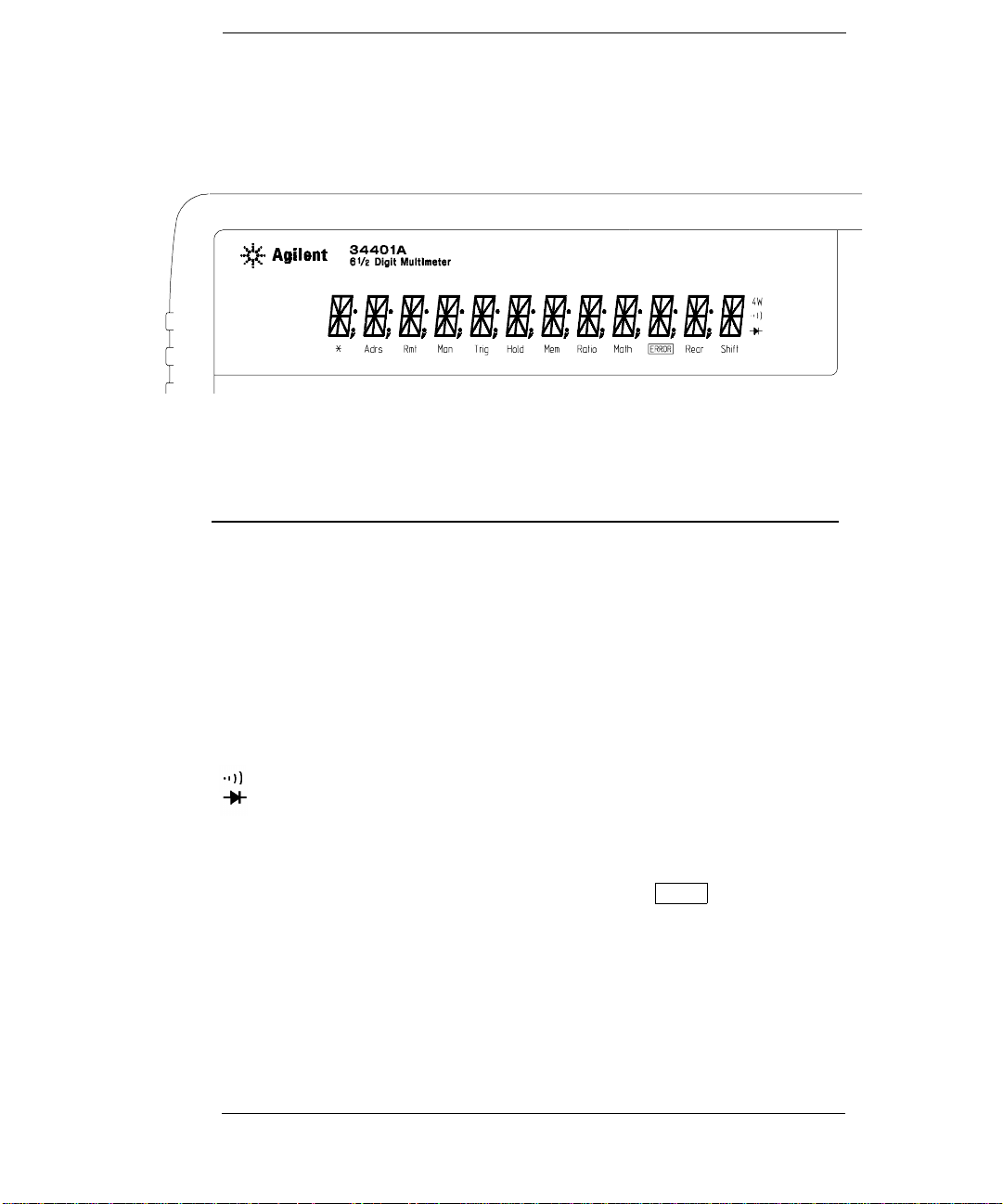
Display Annunciators
∗
Adrs
Rmt
Man
Trig
Hold
Mem
Ratio
Math
ERROR
Rear
Shift
4W
Turns on during a measurement.
Multimeter is addressed to listen or talk over the GPIB interface.
Multimeter is in remote mode (remote interface).
Multimeter is using manual ranging (autorange is disabled).
Multimeter is waiting for a single trigger or external trigger.
Reading Hold is enabled.
Turns on when re ading memory is enabled.
Multimeter is in dcv:dcv ratio function.
A math operation is enabled (null, min-max, dB, dBm, or limit test).
Hardware or remote interface command errors are detected.
Rear input terminals are selected.
“Shift” key has been pressed.
Multimeter is in 4-wire ohms function.
Multimeter is in continuity test function.
Multimeter is in diode test function.
Press “Shif t” ag ain to turn off.
To review the display annunciators, hold down the Shift key as you
turn on the multimeter.
4

The Rear Panel at a Glance
1 Chassis Ground
2 Power-Line Fuse-Holder Assembly
3 Power-Line Voltage Setting
4 Front and Rear Current Input Fuse
5 Voltmeter Complete Output Terminal
6 External Trigger Input Terminal
7 GPIB (IEEE-488) Interface connector
8 RS-232 interface connector
Use the front-panel Input / Output Menu to:
• Select the GPIB or RS-232 interface (see chapter 4 in the “User’s Guide”).
• Set the GPI B bus addr ess (see chapter 4 in the “User’s Guide”).
• Set the RS-232 baud rate and parity (see chapter 4 in the “User’s Guide”).
5

In This Book
Specifications Chapter 1 lists the multimeter’s specifications and
describes how to interpret these specifications.
Quick Start Chapter 2 prepares the multimeter for use and helps you
get familiar with a few of its front-panel features.
Menu Tutorial Chapte r 3 introduces you to the front-panel menu and
steps you through several si mple menu example s.
Calibration Procedures Chapter 4 provides a detailed des c ri ption of
the multimeter’s calibrations and adjustments.
Theory of Operation Chapter 5 describes each functional block in the
multimeter.
Service Chapter 6 provides guidelines for returning your multimeter
to Agilent for servicing, or for servicing it yourself.
Replaceable Parts Chapter 7 contains a detailed parts list of the
multimeter.
Backdating Chapter 8 describes the procedures involved with back
issues of this manu al .
Schematics Chapter 9 provides the multimeter’s schematics.
If you have questions relating to the operation of the Agilent 34401A,
call 1-800-452-4844 in the United States, or contact your nearest
Agilent Sal es Of fic e .
If your 34401A fails within three years of purchase, Agilent will repair
or replace i t free of charge. Call 1-877-444-7278 (“Agilent Express”) in
the United State s, or con tact your n ear est A gile nt Sales Office.
6

Contents
Chapter 1 Specifications
DC Characteristics 12
AC Characteristics 14
Frequency and Period Characteristics 16
General Information 18
Product Dim ensions 19
To Calculate Tota l Me asur em en t Err or 20
Interpreting Multimeter Specifications 22
Configur ing for Highest A ccuracy Measurements 25
Chapter 2 Quick Start
To Prepare the Multimeter for Use 29
If th e M u ltimeter Does Not Turn On 30
To Adjust the Carrying Handle 32
To Measure Voltage 33
To Measure Resistance 33
To Measure Curr en t 34
To Measure Frequ en c y (or Per i od) 34
To Test Continui ty 35
To Check Diod es 35
To Select a Range 36
To Set the Resolution 37
To Make Null (Relative) Measurements 38
To Store Minimum and Maximum Readings 39
To Make dB Measur emen t s 40
To Make dBm Measur em en ts 41
To Trigger the Multimeter 42
To Make dcv:dcv Ratio M eas urem e nts 43
Front-Panel Displ ay For ma ts 44
To Rack Mount the Mu lti met er 45
Contents
Chapter 3 Menu Tutorial
Front-Panel Me nu Refer en c e 49
A Front-Panel Me n u Tutor ial 51
Menu Examples 53
7

Contents
Contents
Chapter 4 Calibration Procedures
Agilent Calibration Services 61
Calibration Interval 61
Time Required for Calibration 61
Automating Cal ibration Pr ocedures 62
Recommended Test Equipment 63
Test Considerations 64
Performance Verification Tests 65
Zero Offs et Verificati on 67
Gain Verification 69
Optional AC Performance Verification Tests 72
Calibration Security Code 73
Calibration Count 75
Calibration Message 75
Calibratio n Proc edu r es 76
Aborting a Calibration in Progress 76
Zero Adjust m ent 77
Gain Adjustment 79
Optional Gain Calibration Procedures 82
Understanding the AC Signal Filter 85
Understanding Resolution 86
Erro r M e s sa g e s 89
Chapter 5 Theory of Operation
Block Diagram 93
Front/Rear Selection 94
Function Switching 95
DC Amplifier 96
Ohms Current Source 98
AC Circuit 99
A-to-D Converter 101
Floating Logic 103
Earth-Referenced Logic 105
Power Supplies 106
Front Panel 107
8

Contents
Chapter 6 Service
Operating Checklist 111
Types of Service Available 112
Repackaging for Shipment 113
Electrostatic Discharge (ESD) Precautions 114
Surface Mount Repair 114
To Replace the Powe r- Lin e Fuse 114
To Replace The Current Input Fuses 115
To Connect Pass/Fai l O utpu t Sign al s 115
Troublesh ooti n g Hint s 117
Self-Test Procedu r es 120
Chapter 7 Replaceable Parts
To Order Replaceable Parts 126
Backdating and Part Changes 126
Replaceable Parts: 34401-66501 (Main Assembly) 127
Replaceable Parts: 34401-66512 (Display Assembly) 133
Replaceable Parts: Agilent 34401A Mainframe 134
Manufacturer’s List 135
Chapter 8 Backdating 137
Chapter 9 Schematics
Mechanical Disassembly 9-3
Component Locator Diagram – Main Board (34401-66501) 9-5
Component Locator Diagram – Front Panel (34401-66512) 9-6
Agilent 34401A Block Diagram 9-7
Front/Rear Selection Schematic 9-8
Function Switching Schematic 9-9
DC Amplifier and Ohms Schematic 9-10
AC Circuit Schematic 9-11
A/D Converter Schematic 9-12
Floating Logic Schematic 9-13
Earth-Referenced Logic Schematic 9-14
Power Supplies Schematic 9-15
Front-Panel Display Schematic 9-16
Contents
9

Contents
10

1
1
Specifications

Chapter 1 Specific ations
DC Characteristics
DC Characteristics
Function
DC Voltage 100.000 0 mV
Range [ 3 ]
1.000000 V
10.00000 V
100.000 0 V
1000.00 0 V
Test Current or
Burden Voltage
Accuracy Specifications ± ( % of reading + % of range ) [ 1 ]
24 Hour [ 2 ]
23°C
± 1°C
0.0030 + 0.0030
0.0020 + 0.0006
0.0015 + 0.0004
0.0020 + 0.0006
0.0020 + 0.0006
90 Day
23°C
± 5°C
0.0040 + 0.0035
0.0030 + 0.0007
0.0020 + 0.0005
0.0035 + 0.0006
0.0035 + 0.0010
1 Year
23°C ± 5°C
0.0050 + 0.0035
0.0040 + 0.0007
0.0035 + 0.0005
0.0045 + 0.0006
0.0045 + 0.0010
Temperature
Coefficient /°C
0°C – 18°C
28°C – 55°C
0.0005 + 0.0005
0.0005 + 0.0001
0.0005 + 0.0001
0.0005 + 0.0001
0.0005 + 0.0001
Resistance
[ 4 ]
DC Current 10.00000 mA
Continuity 1000.0
Diode Test
[12]
DC:DC Ratio 100 mV
Transfer Accuracy ( typical )
100.0000
1.000000 kΩ
10.00000 kΩ
100.000 0 kΩ
1.000000 MΩ
10.00000 MΩ
100.000 0 MΩ
100.000 0 mA
1.000000 A
3.000000 A
1.00 00 V 1 mA 0.002 + 0.010 0.008 + 0.020 0.010 + 0.020 0.001 + 0.002
to
1000 V
( 24 hour %
Ω
Ω 1 mA 0.002 + 0.010 0.008 + 0.020 0.010 + 0.020 0.001 + 0.002
of range error )
1 mA
1 mA
100
10
µA
5
µA
500 nA
500 nA || 10 M
< 0.1 V
< 0.6 V
< 1 V
< 2 V
2
µA
0.0030 + 0.0030
0.0020 + 0.0005
0.0020 + 0.0005
0.0020 + 0.0005
0.002 + 0.001
0.015 + 0.001
0.300 + 0.010
Ω
0.005 + 0.010
0.01 + 0.004
0.05 + 0.006
0.10 + 0.020
( Input Accuracy ) + ( Reference Accuracy )
Input Accuracy = accuracy specification for the HI-LO input signal.
Reference Accuracy = accuracy specification for the HI-LO reference input signal.
Conditions:
Within 10 minutes and ± 0.5°C.
Within
Following a 2-hour warm-up.
Fixed range between 10% and 100% of fu ll scale.
Using 6
Measurements are made using accepted metrology practices.
0.008 + 0.004
0.008 + 0.001
0.008 + 0.001
0.008 + 0.001
0.008 + 0.001
0.020 + 0.001
0.800 + 0.010
0.030 + 0.020
0.030 + 0.005
0.080 + 0.010
0.120 + 0.020
±10% of initial value.
1
⁄
digit slow resoluti on ( 100 PLC ).
2
0.010 + 0.004
0.010 + 0.001
0.010 + 0.001
0.010 + 0.001
0.010 + 0.001
0.040 + 0.001
0.800 + 0.010
0.050 + 0.020
0.050 + 0.005
0.100 + 0.010
0.120 + 0.020
0.0006 + 0.0005
0.0006 + 0.0001
0.0006 + 0.0001
0.0006 + 0.0001
0.0010 + 0.0002
0.0030 + 0.0004
0.1500 + 0.0002
0.002 + 0.0020
0.002 + 0.0005
0.005 + 0.0010
0.005 + 0.0020
12

Chapter 1 Specific ations
DC Characteristics
1
Measuring Characteristics
DC Voltage
Measurement Method:
A/D Linearity:
Input Resistance:
0.1 V, 1 V, 10 V ranges
100 V, 1000 V ranges
Input Bias Current:
Inpu t Terminals:
Input Protection:
Resistance
Measurement Method:
Max. Lead Resistance:
(4-wire ohms)
Input Protection:
DC Current
Shunt Resistor:
Input Protection:
Continuity / Diode Test
Response Time:
Continuity Threshold:
DC:DC Ratio
Measurement Method:
Input HI-LO
Reference HI -I np ut LO
Input to Refe ren ce
Measurement Noise Rejection
60 Hz ( 50 Hz ) [ 5 ]
DC CMRR
Integration Time
100 PLC / 1.67s (2s)
10 PLC / 167 ms (200 ms)
1 PLC / 16.7 ms (20 ms)
0.2 PLC / 3 ms (3 ms)
0.02 PLC / 400
µs (400 µs)
[12] Accuracy specificat ions are for the voltage measur ed at
the input terminals only. 1mA test current is typical. Variation
in the current source will create some variation in the voltage
drop ac ross a diode junction.
Continuously integrating, multi-slope III
A/D conv ert e r.
0.0002% of reading + 0.0001% of range
Selectable 10 M
Ω or >10 GΩ [11]
10 MΩ ±1%
< 30 pA at 25°C
Copper alloy
1000 V on all ranges
Selectable 4-wire or 2-wire ohms.
Current source referenced to LO input.
10% of range per lead for 100
ranges. 1 k
Ω per lead on all other ranges.
Ω, 1 kΩ
1000 V on all ranges
Ω for 1A, 3A. 5Ω for 10 mA, 100 mA
0.1
Externally accessible 3A, 250 V fuse
Internal 7A, 250 V fuse
300 samples/sec with audible tone
Adjustable from 1
Ω to 1000 Ω
Input HI-LO / Reference HI-LO
100 mV to 1000 V ranges
100 mV to 10 V ranges (autoranged)
Reference LO to Input LO voltage < 2 V
Reference HI to Input LO voltage < 12V
140 dB
Normal Mode Rejection [ 6 ]
60 dB [ 7 ]
60 dB [ 7 ]
60 dB [ 7 ]
0 dB
0 dB
Teflon is a registered trademark of E.I. duPont deNemours and Co.
Operating Characteristics [ 8 ]
Additional
Function
DCV, DCI, and
Resistance
System Speeds
Digits
6
6
5
5
4
[ 9 ]
1
⁄
2
1
⁄
2
1
⁄
2
1
⁄
2
1
⁄
2
Readings/s
0.6 (0.5)
6 (5)
60 (50)
300
1000
Funct ion Change
Range C ha ng e
Autorange Time
ASCII readings to RS-232
ASCII readings to GPIB
Max. Internal Trigger Rate
Max. External Trigger Rate to Memory
Max. External Trigger Rate to GPIB
Autozero OFF Operation
Follow ing in st ru men t warm- u p at ca l ib rat i on temp er atu re ±1°C
and <10 minutes, add 0.0002% range additional error + 5 µV.
Settling Considerations
Reading settling times are affected by source impedance,
cable dielectric characteristics, and input signal changes.
Measurement Considerations
Agilent recommends the use of Teflon
low-dielectric absorption wire insulation for these measurements.
[ 1 ] Specifications are for 1-hour warm-up at 6
[ 2 ] Relat ive to calibr ation standar ds.
[ 3 ] 20% overrange on all ranges, except 1000 Vdc, 3 A range.
[ 4 ] Specifications are for 4-wire ohms func tion, or 2-wir e
ohms using Math Null. Without Math Null, add 0.2
additional error in 2-wire ohms function.
[ 5 ] For 1 kΩ unbala nc e in LO lead .
[ 6 ] For power-line frequency ± 0.1%.
[ 7 ] For power-line frequency ± 1%, subtract 20 dB.
For
[ 8 ] Readings speeds for 60 Hz and ( 50 Hz ) operation,
Autozero Off.
[ 9 ] Speeds are for 4
and Display OFF. Includes measurement and data
transfer over GPIB.
[ 10 ] Add 20 µV for dc volts, 4 µA for dc current, or
20 m
[ 11 ] For these ranges, inputs beyond ±17V are
clamped through 100 k
± 3%, subtract 30 dB.
1
⁄
digits, Dela y 0, A uto ze r o OF F,
2
Ω for resistance.
Ω (typical).
Noise Error
0% of range
0% of range
0.001% of range
0.001% of range
0.01% of range
26/sec
50/sec
<30 ms
55/sec
1000/sec
1000/sec
1000/sec
900/sec
â
or other high-impedance,
1
⁄
digits.
2
[10]
[10]
Ω
13

Chapter 1 Specific ations
AC Characteristics
AC Characteristics
Accuracy Spe cificati ons ± ( % of reading + % of range ) [ 1 ]
Function Range [ 3 ] Frequency
True RMS
AC Voltage
[ 4 ]
True RMS
AC Current
[ 4 ]
Additional Low Frequency Errors ( % of reading )
100.000 0 mV
1.00 0000 V
to
750.000 V
1.000000 A
3.00 000 A
Frequency
10 Hz – 20 Hz
20 Hz – 40 Hz
40 Hz – 100 Hz
100 Hz – 200 Hz
200 Hz – 1 kHz
> 1 kHz
3 Hz – 5 Hz
5 Hz – 10 Hz
10 Hz – 20 kHz
20 kHz – 50 kHz
50 kHz – 100 kHz
100 kHz – 300 kHz
3 Hz – 5 Hz
5 Hz – 10 Hz
10 Hz – 20 kHz
20 kHz – 50 kHz
50 kHz – 100 kHz
100 kHz – 300 kHz [6]
3 Hz – 5 Hz
5 Hz – 10 Hz
10 Hz – 5 kHz
3 Hz – 5 Hz
5 Hz – 10 Hz
10 Hz – 5 kHz
AC Filter
Slow Medium Fast
0 0.74 ––
0 0.22 ––
0 0.06 0.73
0 0.01 0.22
0 0 0.18
0 0 0
[6]
[5]
24 Hour [ 2 ]
± 1°C
23°C
1.00 + 0.03
0.35 + 0.03
0.04 + 0.03
0.10 + 0.05
0.55 + 0.08
4.00 + 0.50
1.00 + 0.02
0.35 + 0.02
0.04 + 0.02
0.10 + 0.04
0.55 + 0.08
4.00 + 0.50
1.00 + 0.04
0.30 + 0.04
0.10 + 0.04
1.10 + 0.06
0.35 + 0.06
0.15 + 0.06
Additional Crest Factor Errors ( non-sinewave ) [ 7 ]
90 Day
23°C
± 5°C
1.00 + 0.04
0.35 + 0.04
0.05 + 0.04
0.11 + 0.05
0.60 + 0.08
4.00 + 0.50
1.00 + 0.03
0.35 + 0.03
0.05 + 0.03
0.11 + 0.05
0.60 + 0.08
4.00 + 0.50
1.00 + 0.04
0.30 + 0.04
0.10 + 0.04
1.10 + 0.06
0.35 + 0.06
0.15 + 0.06
Crest Factor
1 – 2
2 – 3
3 – 4
4 – 5
1 Year
23°C ± 5°C
1.00 + 0.04
0.35 + 0.04
0.06 + 0.04
0.12 + 0.05
0.60 + 0.08
4.00 + 0.50
1.00 + 0.03
0.35 + 0.03
0.06 + 0.03
0.12 + 0.05
0.60 + 0.08
4.00 + 0.50
1.00 + 0.04
0.30 + 0.04
0.10 + 0.04
1.10 + 0.06
0.35 + 0.06
0.15 + 0.06
Erro r ( % of r eadi ng )
0.05%
0.15%
0.30%
0.40%
Temperature
Coefficient/°C
0°C – 18°C
28°C – 55°C
0.10 0 + 0.004
0.03 5 + 0.004
0.00 5 + 0.004
0.01 1 + 0.005
0.06 0 + 0.008
0.20 + 0.02
0.10 0 + 0.003
0.03 5 + 0.003
0.00 5 + 0.003
0.01 1 + 0.005
0.06 0 + 0.008
0.20 + 0.02
0.10 0 + 0.006
0.03 5 + 0.006
0.01 5 + 0.006
0.10 0 + 0.006
0.03 5 + 0.006
0.01 5 + 0.006
Sinewave Transfer Accuracy ( typical )
Frequency
10 Hz – 50 kHz
50 kHz – 300 kHz
Error ( % of r ange )
0.002%
0.005%
14
Conditions:
Sinewave input.
Within 10 minutes and ± 0.5°C.
Within ±10% of initia l volt ag e and ±1% of initial frequency.
Following a 2-hour warm-up.
Fixed range between 10% and 100% of full scale ( and <120 V ).
Using 6
Measur ements are made using accepted metrology practices.
1
⁄
digit resolution.
2

Chapter 1 Specific ations
AC Characteristics
1
Measuring Characteristics
Measurement Noise Rejection
AC CMRR
True RMS AC Voltage
Measurement Method:
Crest Factor:
AC Fil ter Bandwidth:
Slow
Medium
Fast
Input Impedance:
Input Protection:
True RM S AC Curr ent
Measurement Method:
Shunt Resistor:
Burden Voltage:
Input Protection:
Settling Conside ration s
Applying >300 V rms (or >1 A rms) will cause self-heating in
signal-c on ditionin g co mp on ents. Thes e err o rs ar e inc lu de d in
the instrument specifications. Internal temperature changes
due to s elf-heating may cause addit ional error on lower ac
voltage ranges. The additional error will be less than 0.02%
of reading and will generally dissipate within a few minutes.
[ 8 ]
70 dB
AC-c oupl ed Tr ue R MS – measures
the ac component of input with up
to 400 Vdc of bias on any r ange.
Maximum 5:1 at full scale
3 Hz – 300 kHz
20 Hz – 30 0 kHz
200 Hz – 300 kHz
1 M
Ω ± 2%, in parallel with 100 pF
750 V rms all ranges
Direct coupled to the fuse and shunt.
AC-coupled True RMS measurement
(measures the ac component only).
0.1
Ω for 1 A and 3 A ranges
1 A range: < 1 V rms
3 A range: < 2 V rms
Exter na lly ac ce ss ib l e 3A, 25 0 V f us e
Internal 7A, 250 V fuse
Operating Characteristics [ 9 ]
Function
Digits
ACV, ACI 6
System Speeds
1
⁄
1
6
⁄
1
6
⁄
1
6
⁄
1
6
⁄
[ 11 ] , [ 12 ]
2
2
2
2
2
Reading/s
7 sec/reading
1
1.6
10
50
Functio n or Ra ng e C ha ng e
Autora ng e Tim e
ASCII readings to RS-232
ASCII readings to GPIB
Max. Internal Trigger Rate
Max. External Trigger Rate to Memory
Max. External Trigger Rate to GPIB/RS-232
[ 1 ] Specifications are for 1-hour warm-up at 6
Slow ac filter, sinewave input.
[ 2 ] Relative to calibration standards.
[ 3 ] 20% overrange on all ranges, except 750 Vac, 3 A range.
[ 4 ] Specifications are for sinewave input >5% of range.
For inputs from 1% to 5% of range and <50 kHz,
add 0.1% of range additional error. For 50 kHz to 100 kHz,
add 0.13% of range.
[ 5 ] 750 Vac ran ge limited to 100 kHz or 8x10
[ 6 ] Typically 30% of reading error at 1 MHz.
[ 7 ] For frequencies below 100 Hz, slow AC filter specified
for sinewave input only.
[ 8 ] For 1 kΩ unbalance in LO lead.
[ 9 ] Maximum reading rates for 0.01% of ac step
additional error. Additional settling delay required
when input dc level varies.
[ 10 ] For Externa l Trigger or remote operation using defaul t
settling delay ( Delay Auto ).
[ 11 ] Maximum useful limit with default settling delays defeated.
[ 12 ] Speeds are for 4
1
⁄
digits, Delay 0, Display OFF, and
2
Fast AC filte r.
[ 10 ]
[ 11 ]
AC Filter
Slow
Medium
Fast
Fast
Fast
5/sec
<0.8 sec
50/sec
50/sec
50/sec
50/sec
50/sec
1
⁄
digits,
2
7
Volt-Hz.
15

Chapter 1 Specific ations
Frequency and Period Characteristics
Frequency and Period Characteristics
Accuracy Specifications ± ( % of reading ) [ 1 ]
Function Range
Frequency,
Period [ 4 ]
[ 3 ] Frequency
100 mV
to
750 V
3 Hz – 5 Hz
5 Hz – 10 Hz
10 Hz – 40 Hz
40 Hz – 300 kHz
Additional Low-Frequency Errors ( % of reading )
Frequency
3 Hz – 5 Hz
5 Hz – 10 Hz
10 Hz – 40 Hz
40 Hz – 100 Hz
100 Hz – 300 Hz
300 Hz – 1 kHz
> 1 kHz
1
6
⁄
2
0 0.12 0.12
0 0.17 0.17
0 0.2 0.2
0 0.06 0.21
0 0.03 0.21
0 0.01 0.07
0 0 0.02
5
1
⁄
4
2
Resolution
Transfer Accuracy ( typical )
0.0005 % of reading Conditions:
24 Hour
[ 2 ]
23°C ± 1°C
90 Day
23°C
± 5°C
1 Year
23°C ± 5°C
Temperature
Coefficient/°C
0°C – 18°C
28°C – 55°C
0.005
0.005
0.001
0.001
[ 4 ]
0.10
0.05
0.03
0.006
1
⁄
2
0.10
0.05
0.03
0.01
0.10
0.05
0.03
0.01
Within 10 minutes and ± 0.5°C.
Within ± 10% of initial value.
Following a 2-hour warm-up.
For inputs > 1 kHz and > 100 mV.
Using 6
1
⁄
digit slow resolution ( 1 second gate time ).
2
Measure ments are made usi ng accepted metrology practi ces.
16

Chapter 1 Specific ations
Frequency and Period Characteristics
1
Measuring Characteristics
Frequency a nd Period
Measurement Method:
Voltage Ranges:
Gate Time:
Settling Considerations
Errors wil l oc cu r wh en at t emp tin g t o meas ur e the f req ue nc y o r
period of an i nput f ol low i ng a dc off se t v olt ag e ch an ge . Th e i np ut
blocking RC time constant must be allowed to fully settle ( up to
1 sec ) before the most accurate measurements are possible.
Measurement Considerations
All frequency count ers are susceptible to error when
measuring low-voltage, low-frequency signals. Shielding
inputs from external noise pickup is critical for minimizing
measurement errors.
Reciprocal-counting technique.
AC-coupled input using the
ac voltage measurement function.
100 mV rms fu ll s ca le to 750 V rms.
Auto or manual rangin g.
10 ms, 100 ms, or 1 sec
Operating Characteristics [ 5 ]
Function
Frequency,
Period
System Speeds
Digits
1
6
⁄
2
1
5
⁄
2
1
4
⁄
2
[ 5 ]
Configuration Rates
Autora ng e Tim e
ASCII readings to RS-232
ASCII readings to GPIB
Max. Internal Trigger Rate
Max. External Trigger Rate to Memory
Max. External Trigger Rate to GPIB/RS-232
[ 1 ] Specifications are for 1- hour warm-up at 6
[ 2 ] Relative to calibration standards.
[ 3 ] 20% overrange on all ranges, except 750 Vac range.
[ 4 ] Input > 100 mV.
For 10 mV input, multiply % of reading error x10.
[ 5 ] Speeds are for 4
1
⁄
digits, Delay 0, Display OFF,
2
and Fast AC filter.
Reading/s
1
9.8
80
14/sec
<0.6 sec
55/sec
80/sec
80/sec
80/sec
80/sec
1
⁄
digit s.
2
17

Chapter 1 Specific ations
Gene r a l Informatio n
General In formation
General Specifications
Power Supply:
Power Line Frequency:
Power Consumption:
Operating Environment:
Storag e Env ironment:
Rack Dimensions (HxWxD):
Weight:
Safety:
EMI:
Vibration and Shock:
Warranty:
Accessories Included
Test Lead Kit with probes, alligator, and grabber attachments.
User’s Guide, Service Guide, test report, and power cord.
100 V / 12 0 V / 220 V / 24 0 V
45 Hz to 66 Hz and 360 Hz to 440 Hz.
Automatically sensed at power-on.
25 VA peak ( 10 W avera ge )
Full accuracy for 0
Full accuracy to 80% R.H. at 40°C
-40°C to 70°C
88.5 mm x 212.6 mm x 348.3 mm
3.6 kg (8 lbs)
Designed to CSA 231, UL 1244,
IEC 1010-1 (1990)
CISPR 11, IEC 801,
MIL-461C (data on file)
MIL-T-28800E Type III, Class 5
(data on file)
3 years stan dard
°C to 55°C
±10%.
Triggering and Memory
Reading
HOLD Sensitivity:
Samples per Trigger:
Trigger Delay:
External Trigge r Delay:
External Trigge r Jitter:
Memory:
Math Functions
Null, Min/Max/Average, dB, dBm, Limit Test (with TTL output).
dBm ref e ren ce resi s ta nc es : 50, 75 , 93, 11 0, 12 4, 12 5, 13 5, 15 0,
250, 300, 500, 600, 800, 900, 1000, 1200, or 8000 ohms.
Standard Programming Languages
SCPI (Standa rd C omm ands fo r Pr ogr amm ab le In st ru men t s)
Agilent 3478A Language Emulati on
Fluke 8840A, Fluke 8842A Language Emulation
Remote Interface
GPIB (IEEE-488.1, IEEE-488.2) and RS-232C
This ISM device complies with Canadian ICES-001.
Cet appareil ISM est co nforme à la norme NMB-001
du Canada.
0.01 %, 0.1% , 1%, or 10% of read ing
1 to 50,000
0 to 36 00 sec ( 10
< 1 ms
< 500
µs
512 readings
µs step size )
18
N10149

Chapter 1 Specific ations
67.53
Product Dimensions
Product Dimensions
Product Dimensions
1
TOP
All dimensions are
shown in millimeter s.
19

Chapter 1 Specific ations
To Calculate Total Measurement Error
To Calculate Total Measurement Error
Each specifi ca t i on includes co rrection factor s whi ch a ccount for error s
present due to operational limitations of the multimeter. This section
explains these errors and shows how to appl y them to your mea suremen ts.
Refer to “Interpreting Multimeter Specifications,” starting on page 22,
to get a better understanding of the terminology used and to help you
interpret the multimeter’s specifications.
The multimeter’s accuracy specifications are expressed in the form:
( % of reading + % of range ). In addition to the reading er ror an d ran g e
error, you may need to add additional errors for certain operating
conditions. Check the list below to make sure you include all
measurement errors for a given function. Also, make sure you apply the
conditions as described in the footnotes on the specification pages.
• If you are operatin g the m ultim e t er outsid e th e 23° C ± 5°C
temperat ure r ange s pec ifi ed , apply an addi tion a l temperature
coeffic ient error.
• For dc voltage, dc current, and resistance measurements, you may
need to apply an additional reading speed error or autozero OFF error.
• For ac voltage and ac current measurements, you may need to apply
an additional low frequency erro r or crest factor error.
Understanding the “ % of reading ” Error The reading error
compensate s fo r i na ccuracies that re sul t fr om t he function and range
you select, as well as the input signal level. The reading error varies
according to the input level on the selected range. This error is
expressed in percent of reading. The following table shows the reading
error applied to the multimeter’s 24-hour dc voltage specification.
Range
10 Vdc
10 Vdc
10 Vdc
Input Level
10 Vdc
1 Vdc
0.1 Vdc
Reading Error
(% of reading)
0.0015
0.0015
0.0015
Reading
Error Voltage
≤ 150 µV
≤ 15 µV
≤ 1.5 µV
20

Chapter 1 Specific ations
To Calculate Total Measurement Error
Understandi ng th e “ % of rang e ” Error The range error compensates
for inaccuracies that result from the function and range you select.
The range erro r con trib u tes a cons ta nt er r or , expr esse d as a percen t of
range, independent of the input signal level. Th e follow in g ta bl e show s
the range error applied to the multimeter’s 24-hou r dc v oltage speci fication.
1
Rang e
10 Vdc
10 Vdc
10 Vdc
Input Level
10 Vdc
1 Vdc
0.1 Vdc
Range Error
(% of range)
0.0004
0.0004
0.0004
Range
Error Voltage
≤ 40 µV
≤ 40 µV
≤ 40 µV
Total Measurement Error To compute the total measurement error,
add the reading error and range error. You can then convert the total
measurement error to a “percent of input” error or a “ppm (part-permillion) of input” error as shown below.
% of input error =
ppm of input error =
Total Measurement Error
Inp u t Signal Level
Total Measurement Error
Inp u t Signal Level
× 100
× 1,000,000
Error Example Assume that a 5 Vdc signal is input to the multimeter on the 10 Vdc range.
Compute the total measurement error using the 90-day accuracy
specifications:
± (0.0020% of reading + 0.0005% of range).
Reading Error
Range Error
Total Error
= 0.0020%
= 0.0005%
µV + 50 µV
= 100
× 5 Vdc
× 10 Vdc
= 100 µV
= 50
µV
=
± 150 µV
= ± 0.0030% of 5 Vdc
= ± 30 ppm of 5 Vdc
21

Chapter 1 Specific ations
Interpreting Multimeter Specifications
Interpreting Multimeter Specifications
This section is provided to give you a better understanding of the terminology
used and wil l help you in terpre t the mu ltimete r’s spe cificatio ns.
Number of Digits and Overrange
The “number of digits” specification is the most fundamental, and
sometimes, the most confusing characteristic of a multimeter.
The number of digits is equal to the maximum number of “9’s” the
multimeter can measure or display. This indicates the number of full
digits. Most multimeters have the ability to overrange and add a partial
1
or “
⁄
” digit.
2
For example, the Agilent 34401A can measure 9.99999 Vdc on the 10 V
range. This represents six full digits of resolution. The multimeter can
also overrange on the 10 V range and me asur e up to a maximum of
12.00000 Vdc. This corresponds to a 6
overrange capability.
1
⁄
-digit measurement with 20%
2
Sensitivity
Sensitivity is the minimum level that the multimeter can detect for a
given measurement. Sensitivity defines the ability of the multimeter to
respond to small changes in the input level. Fo r example, suppose you
are monitoring a 1 mVdc signal and you want to adjust the level to
within
measurement w ould re quire a multim eter with a sen sitivit y of at least 1
You could use a 6
You could also use a 4
For ac voltage and ac current measurements, note that the smallest
value that can be measured is different from the sensitivity. For the
Agilent 34401A, these functions are specified to measure down to 1% of
the selected range. For example, the multimeter can measure down to
1 mV on the 100 mV range.
22
±1 µV. To be able to respond to an adjustme nt this smal l, this
1
⁄
-digit multimeter if it has a 1 Vdc or smaller range.
2
1
⁄
-digit multimeter with a 10 mVdc range.
2
µV.

Chapter 1 Specific ations
Interpreting Multimeter Specifications
Resolution
Resolution is the numeric ratio of the maximum displayed value divided
by the minimum dis pla yed valu e on a selec ted r a nge. Reso lution is
often expressed in percent, parts-per-million (ppm), counts, or bits.
For example, a 6
1
⁄
-digit multimeter with 20% overrange capability can
2
display a measurement with up to 1,200,000 counts of resolution.
This corresponds to about 0.0001% (1 ppm) of full s cale, or 21 bits
including the sign bit. All four specifications are equivalent.
Accuracy
Accuracy is a measure of the “exactness” to which the multimeter’s
measurement uncertainty can be determined relative to the calibration
reference used. Absolute accuracy includes the multimeter’s relative
accuracy specification plus the known error of the calibration reference
relative to national standards (such as the U.S. National Institute of
Standards and Technology). To be meaningful, the accuracy specifications
must be accompanied with the conditions under which they are valid.
These conditions should include temperature, humidity, and time.
1
There is no standar d co nv en tion a mon g mu lt im eter man u fac tu re rs for
the confidence limits at which specifications are set. The table below
shows the probability of non-conformance for each specificatio n with the
given assumptions.
Specification
Criteria
Mean
± 2 sigma
Mean
± 3 sigma
Mean
± 4 sigma
Probability
of Failure
4.5%
0.3%
0.006%
Variations in performance from reading to reading, and instrument to
instrument, decrease for increasing number of sigma for a given
specification. This means that you c an a chi eve greater act ual m easurement
precision for a specific accuracy specification number.
The Agilent 34401A is designed and tested to meet performance better
than mean
±4 sigma of the published accuracy specifications.
23

Chapter 1 Specific ations
Interpreting Multimeter Specifications
Transfer Accuracy
Transfer accuracy refers to t he error introduce d by the multimeter
due to noise and short-term drift. This error becomes apparent when
comparing two nearly-equal signals for the purpose of “transf erring”
the known ac cur a c y of one dev ic e to the ot h er .
24-Hour Accuracy
The 24-hour accuracy specification indicates the multimeter’s relative
accuracy over its full measurement range for short time intervals and
within a stable environment. Short-term accuracy is usually specified
for a 24-hour period and for a
±1°C temperatu r e ran g e.
90-Day and 1-Year Accuracy
These long-term accuracy specifications are valid for a 23°C ± 5°C
temperature range. These specifications include the initial calibration
errors plus the multimeter’s long-term drift errors.
Temperature Coefficients
Accuracy is usually specified for a 23°C ± 5°C temperature range.
This is a common temperature range for many operating environments.
You must add additional temperature coefficient errors to the accuracy
specification if you are operating the multimeter outside a 23°C ± 5°C
temperature range (the specification is per °C).
24

Chapter 1 Specific ations
Configuring for Highest Accuracy Measurements
Configuring for Highest Accuracy Measurements
The measurement configurations shown below assume that the
multimeter is in its power-on or reset state. It is also assumed that
manual ranging is enabled to e nsure proper full scale range selection.
DC Voltag e, DC Current, and Resistance Measurements:
• Set the resolution to 6 digits (you can use the 6 dig its slow mode for
further nois e reduction).
• Set the input resistance to greater than 10 GΩ (for the 100 mV, 1 V,
and 10 V ranges) for the best dc voltage accuracy.
• Use 4-wire ohms for t he best resistance acc uracy.
• Use Math Null to null the test lead resistance for 2-wire ohms, and to
remove interconnection offset for dc voltage measurements.
1
AC Voltage and AC Current Measurements:
• Set the resolution to 6 digits.
• Select the slow ac filter (3 Hz to 300 kHz).
Frequency and Period Measurements:
• Set the resolution to 6 digits.
25

26

2
2
Quick Start

Quick Start
One of the first things you will want to do with your multimeter is to
become acquainted with its front panel. We have written the exercises
in this chapter to prepare the multimeter for use and help you g et
familiar with some of its front-panel operations.
The front panel has two rows of keys to select various functions and
operations. Most ke ys have a shifted function printed in blue above
the key. To perform a shifted function, press
annunciator will turn on). Then, press the key that has the desired
label above it. For example, to select the dc current function,
Shift DC V .
press
Shift (the Shift
If you accident a l ly press
Shift annunciato r.
The rear cover of this bo ok is a fold -out Qu ick Re feren ce Gu ide. On t his
cover you will fi nd a quick summary of various multi m eter features.
Shift , just press it again to turn off the
28
 Loading...