

Page 1

User’s Guide
Publication number 16522-97007
June 2000
For Safety information, Warranties, and Regulatory
information, see the pages behind the Index
Copyright Agilent Technologies 1987, 1995, 1996, 1997, 1999, 2000
All Rights Reserved
Agilent Technologies 16522A
200-M Vectors/s
Pattern Generator
Page 2

The Agilent Technologies 16522A Pattern Generator
The Agilent Technologies 16522A pattern generator module is an
expandable stimulus tool designed for the Agilent Technologies
16500B/C Logic Analysis System. It provides digital design teams the
ability to emulate missing devices and to functionally test prototypes.
Key Characteristics
Output channels:
MHz clock.
20 channels at 200 MHz clock; 40 channels at 100
Memory depth:
Logic levels (data pods):
ECL terminated, ECL unterminated, and differential ECL (without pod).
Data inputs:
Clock outputs:
9 steps (clock pod).
Clock input:
Internal clock period:
4, 5, 8 sequence.
External clock period (user supplied):
External clock duty cycle:
Maximum number of "IF condition" blocks at 50 MHz clock:
Maximum number of different macros:
Maximum number of lines in a macro:
Maximum number of macro invocations:
Maximum number of Repeat loop invocations:
Maximum number of Wait event patterns:
258,048 vectors.
TTL, 3-state TTL/3.3v, 3-state TTL/CMOS,
3-bit pattern - level sensing (clock pod).
Synchronized to output data, delay of 11 ns in
DC to 200 MHz (clock pod).
Programmable from 5 ns to 250 µs in a 1, 2, 2.5,
DC to 200 MHz.
2 ns minimum high time.
1.
100.
1024.
1,000.
1,000.
4.
ii
Page 3

Agilent Technologies 16522A Pattern Generator
iii
Page 4

iv
Page 5
In This Book
1
2
3
This User’s Guide contains all the
information needed to operate, program,
and service the Agilent Technologies
16522A Pattern Generator module.
Chapter 1 documents many common tasks
that you will perform while using the
pattern generator. Use this chapter as a
quick reference to the product’s operation.
Chapter 2 contains reference information
on the functionality of the menu fields and
product features. Use this chapter for
additional information on feature usage
and limitations.
Chapter 3 documents the programming command set used when controlling
the pattern generator from a computer. Use this chapter for command
reference information when writing your test verification programs.
Chapter 4 contains service procedures for verifying the product’s
performance, board-level troubleshooting, and replacement of the PC board
and cables. Use this chapter if you suspect problems with the pattern
generator.
Chapter 5 contains information on the installation of the pattern generator
module and probe tip assemblies. Use this chapter to configure and install
single and multi-card modules.
Chapter 6 documents how to load user-created pattern generator files as
ASCII files into the pattern generator. Use ASCII file downloading if you
want to create and load files by one of the remote communications interfaces
or load by disk.
4
5
6
Using the Agilent 16522A
Agilent 16522A Reference
Programming the Agilent 16522A
Servicing the Agilent 16522A
Installation
Loading ASCII Files
Index
v
Page 6

vi
Page 7

Contents
1 Using the Agilent Technologies 16522A
Setting Up the Proper Configurations 1–3
To set up the configuration 1–3
To build a label 1–5
Building Test Vectors 1–6
To build a main vector sequence 1–7
To build an initialization sequence 1–8
To edit a main or initialization sequence 1–8
To include hardware instructions in a sequence 1–9
To include software instructions in a sequence 1–10
To include a user macro in a sequence 1–11
To build a user macro 1–12
To modify a macro name 1–13
To edit a macro 1–13
To add, delete, or rename parameters 1–14
To place parameters in a vector 1–15
To enter or modify parameters 1–16
To build a User Symbol Table 1–17
To include symbols in a sequence 1–18
To include symbols in a macro 1–19
To store a configuration 1–20
To load a configuration 1–21
To use Autoroll 1–22
2 Agilent 16522A Reference
The Format Menu 2–3
The Sequence Menu 2–6
The User Macros Menu 2–14
Pod Numbering 2–16
Connecting Pods Directly to a PC Board 2–17
Output Pod Characteristics 2–18
Contents–1
Page 8

Contents
3 Programming the Agilent 16522A
Programming Overview 3–3
Example Pattern Generator Program 3–3
Selecting the Module 3–4
Mainframe Commands 3–5
Command Set Organization 3–8
Module Status Reporting 3–10
Module Level Commands 3–13
STEP 3–14
RESume 3–16
FORMat Subsystem 3–17
CLOCk 3–18
DELay 3–19
LABel 3–20
MODe 3–22
REMove 3–23
SEQuence Subsystem 3–24
COLumn 3–26
EPATtern 3–27
INSert 3–29
PROGram 3–32
REMove 3–35
MACRo Subsystem 3–36
INSert 3–39
NAME 3–42
PARameter 3–43
PROGram 3–44
REMove 3–47
Contents–2
Page 9

SYMBol Subsystem 3–48
BASE 3–50
PATTern 3–51
RANGe 3–52
REMove 3–53
WIDTh 3–54
Data and Setup Commands 3–55
SYSTem:DATA 3–57
SYSTem:SETup 3–58
4 Servicing the Agilent 16522A
Servicing the Agilent 16522A 4–2
Contents
Testing the Agilent 16522A 4–7
To run self-tests 4–8
To run performance verification tests 4–9
To verify pattern output 4–11
To exit the test system 4–13
Self-Tests Descriptions 4–14
Clock Source Test 4–14
Vector Memory Test 4–15
Address Counter Test 4–16
Instruction Tests 4–17
Output Patterns for testing with an external logic analyzer
or oscilloscope 4–20
Theory of Operation 4–21
To replace the board and cable 4–23
Agilent 16522A Replacement Parts 4–24
To clean the pattern generator module 4–26
Contents–3
Page 10

Contents
5 Installation
To inspect the module 5–3
To prepare the mainframe 5–3
To configure a one-card module 5–5
To configure a multi-card module 5–6
To install modules 5–10
6 Loading ASCII files
ASCII file commands 6–3
ASCDown Command 6–3
LABel 6–4
VECTor 6–5
FORMat:xxx 6–7
Loading an ASCII file over a bus (example) 6–8
Loading an ASCII file from a disk (example) 6–11
Index
Contents–4
Page 11

1
Setting Up the Proper Configurations 1–3
To set up the configuration 1–3
To build a label 1–5
Building Test Vectors 1–6
To build a main vector sequence 1–7
To build an initialization sequence 1–8
To edit a main or initialization sequence 1–8
To include hardware instructions in a sequence 1–9
To include software instructions in a sequence 1–10
To include a user macro in a sequence 1–11
To build a user macro 1–12
To modify a macro name 1–13
To edit a macro 1–13
To add, delete, or rename parameters 1–14
To place parameters in a vector 1–15
To enter or modify macro parameters 1–16
To build a User Symbol Table 1–17
To include symbols in a sequence 1–18
To include symbols in a macro 1–19
To store a configuration 1–20
To load a configuration 1–21
To use Autoroll 1–22
Using the Agilent Technologies 16522A
Page 12

Using the Agilent Technologies 16552A
This chapter provides instructions for using the Agilent Technologies
16522A to generate vectors and patterns for design and test
environments. Two sections comprise this chapter:
Setting up the proper configurations
•
Building vectors and macros
•
Because the Agilent 16522A operates in much the same way other
modules in the Agilent 16500B/C mainframe, discussions of general
operation have been eliminated from these procedures. If you have
questions of a general nature, refer to the User’s Reference for the
Agilent 16500.
See chapter 5 for installation instructions.
1–2
Page 13

Setting Up the Proper Configurations
This section discusses setting up the configuration attributes and
parameters of the pattern generator.
If you are reloading existing configurations or downloading ASCII
vector files, refer to the Load operation in the disk drive menus of the
System.
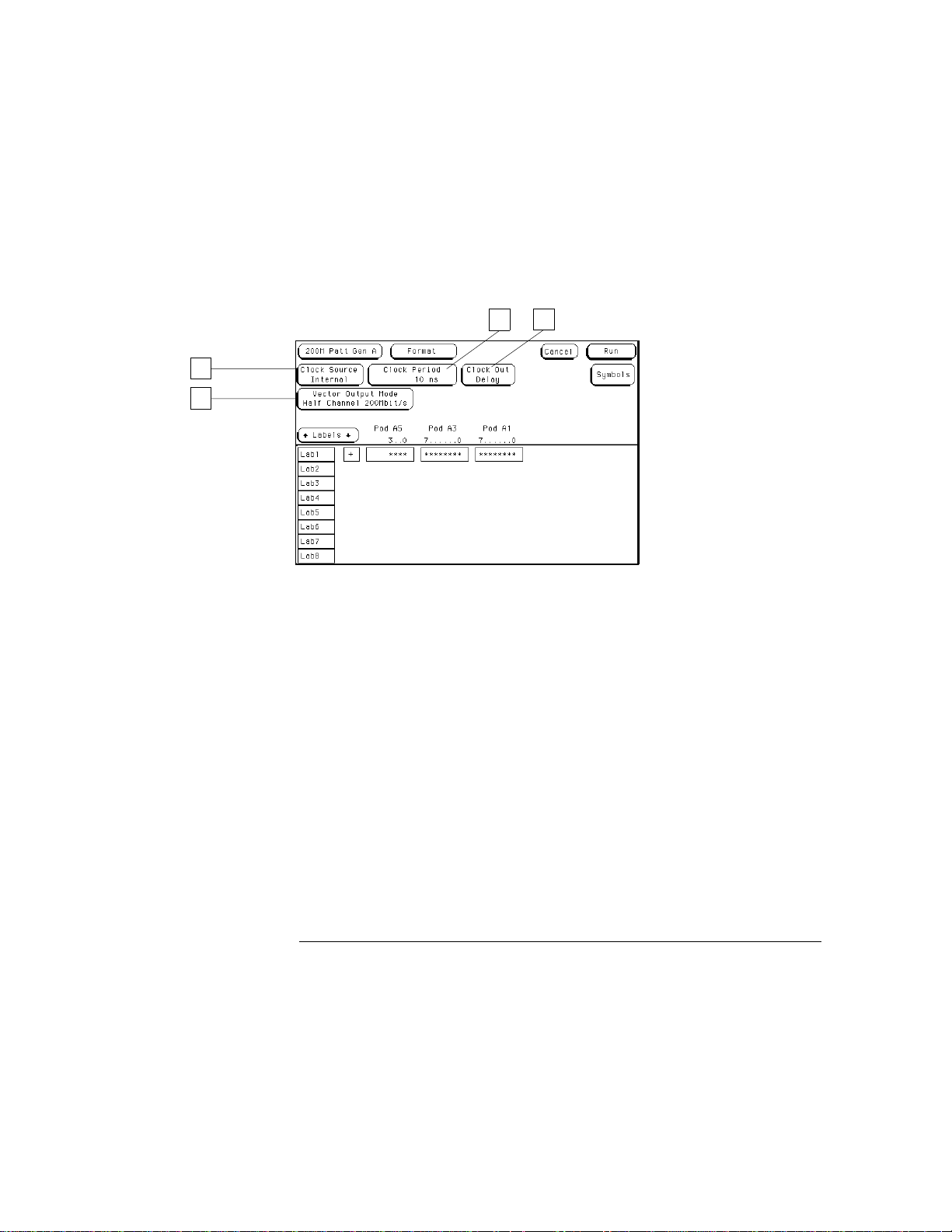
To set up the configuration
1
From the Format menu, set the Vector Output Mode to either full or
half channel.
Make this selection first because clock frequencies and available channels are
affected.
In half channel mode, only pods 1, 3, and 5 are used. Only four channels are
available in pod 5.
2
Set the Clock Source to either internal or external.
An external clock is used when you need a clock frequency that is not
available internally, or if you need to drive the pattern generator timing with
an external reference.
1–3
Page 14
2
1
Using the
Agilent Technologies 16522A
To set up the configuration
3
Set the Clock Period for an internal clock or the Clock Frequency for
an external clock.
The external clock frequency information is required to select the
appropriate operating mode. Operating the pattern generator at an external
clock frequency higher than selected will result in erroneous operation.
4
Set the Clock Out Delay if a delay is needed.
Setting a delay is useful when using the clock out edge as a read strobe. If
you do not set the Clock Out Delay, the value is uncalibrated.
4
3
1–4
Page 15
2
Using the
Agilent Technologies 16522A
To build a label
To build a label
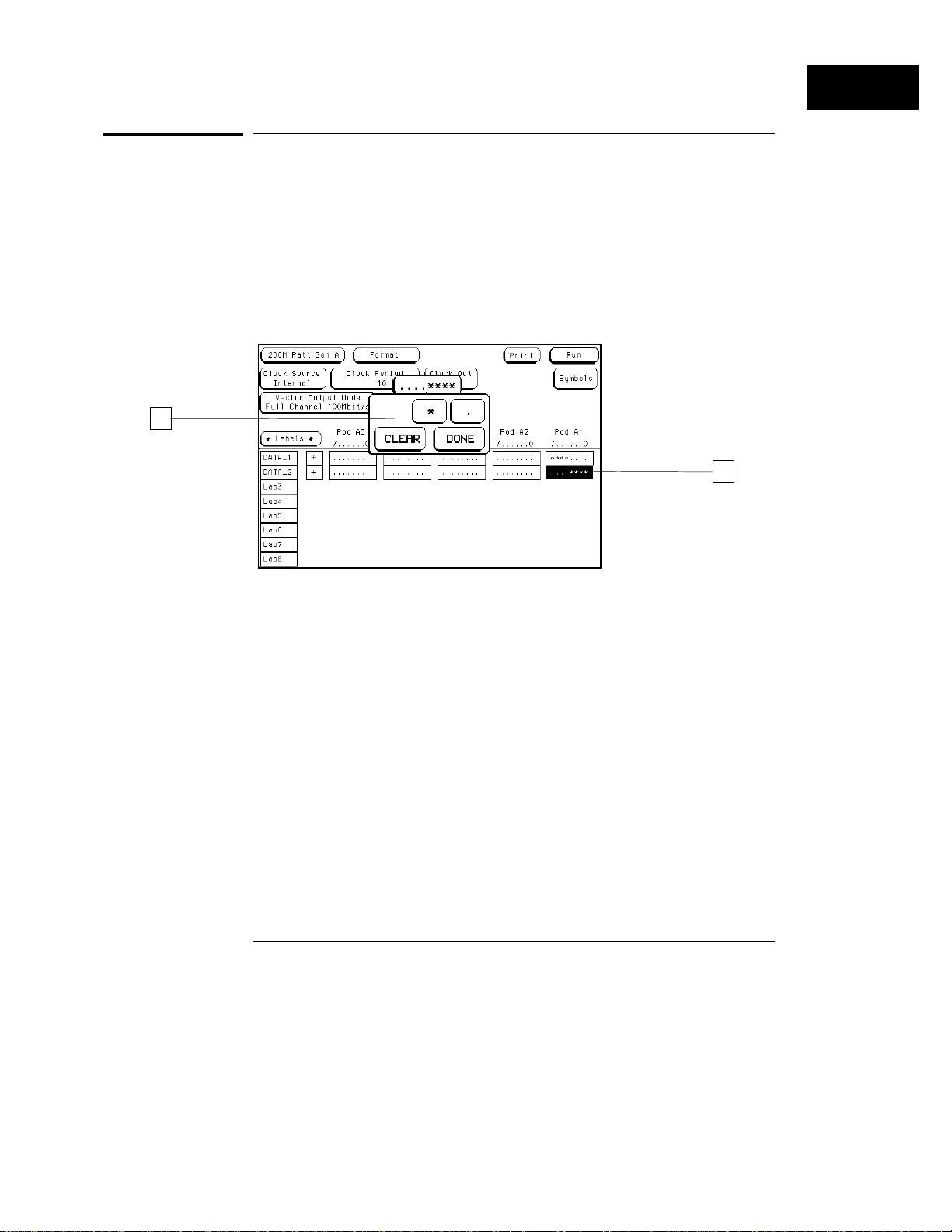
When you build a label, you are grouping channels under a label name and
mapping the selected channels to the probes on the associated pods. A label
may contain up to 32 channels, however, a single channel cannot be used
under more than one label.
For more information on using labels, refer to "Label Assignment" in the
Common Module Operations section of the mainframe manual.
1
Select the label’s channel assignment field.
1
2
Select the desired channels.
* (asterisk) = on
.
(period) = off
Only the selected channels can output pattern generator signals.
3
Select Done.
1–5
Page 16

Building Test Vectors
Once the pattern generator is configured, you will want to build
programs to use in your test system. You build programs in the
Sequence menu. If you have small program segments that are built
from frequently used vectors, they can be built in the User Macros
menu. Once built, they are inserted into the program in the
Sequence menu.
Another way to build programs is to generate them on another
system, then load them as ASCII files. For more information, refer to
"Loading ASCII files" in chapter 6.
1–6
Page 17
Using the
Agilent Technologies 16522A
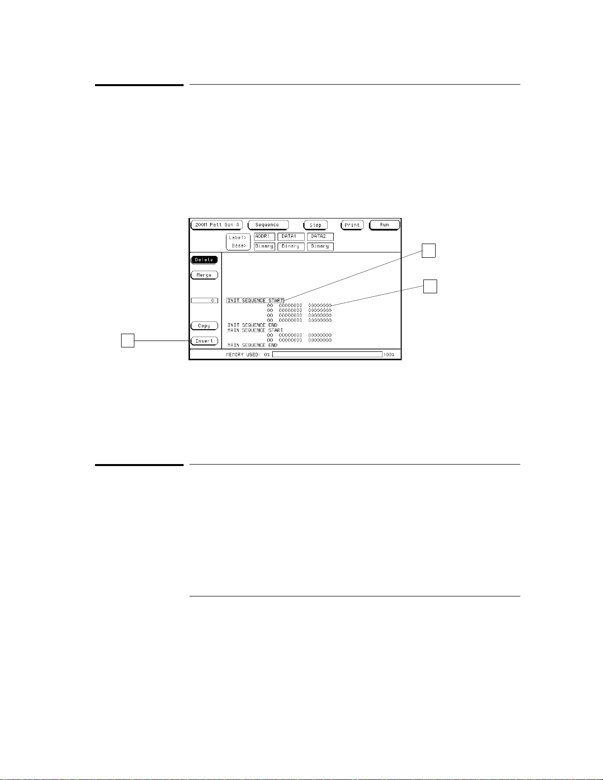
To build a main vector sequence
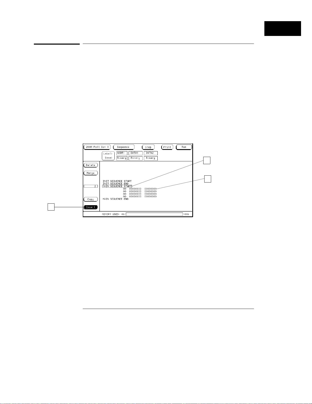
To build a main vector sequence
During a single run, the program vectors in the MAIN SEQUENCE are output
to the system under test in an order of first vector to last vector. The data of
the last vector is then held until run is selected again. During a repetitive
run, the MAIN SEQUENCE loops until stop is selected.
1
From the Sequence menu, use the knob to highlight the first data row.
2
Select the Insert field once for each line of vectors you want inserted
into the main sequence.
These new lines of vectors provide fields to place data into for each label.
3
Select the data field, then type in a data value.
If you will be adding data in many fields, use the Autoroll feature. Refer to
"To use Autoroll" found later in this chapter.
1
3
2
1–7
Page 18
Using the
Agilent Technologies 16522A
To build an initialization sequence
To build an initialization sequence
Use the INIT SEQUENCE to place the system under test into a known
initialization state. Default start and end program vectors are marked INIT
SEQUENCE START and INIT SEQUENCE END. During a repetitive run, the
initialization sequence is only executed the first time the program is run. The
main sequence then loops repetitively.
1
From the Sequence menu, use the knob to highlight INIT SEQUENCE
START.
1
3
2
2
Select the Insert field once for each new line of vectors you want
inserted into the initialization sequence.
These new lines of vectors provide fields to place data into for each label.
3
Select the data field, then type in a data value.
If you are adding data in many fields, use the Autoroll feature. Refer to "To
use Autoroll" found later in this chapter.
To edit a main or initialization sequence
1
Using the knob, highlight the vector you want to edit.
2
Select the data field you want to edit.
3
Select the new instruction or change the data value.
1–8
Page 19
Using the
Agilent Technologies 16522A
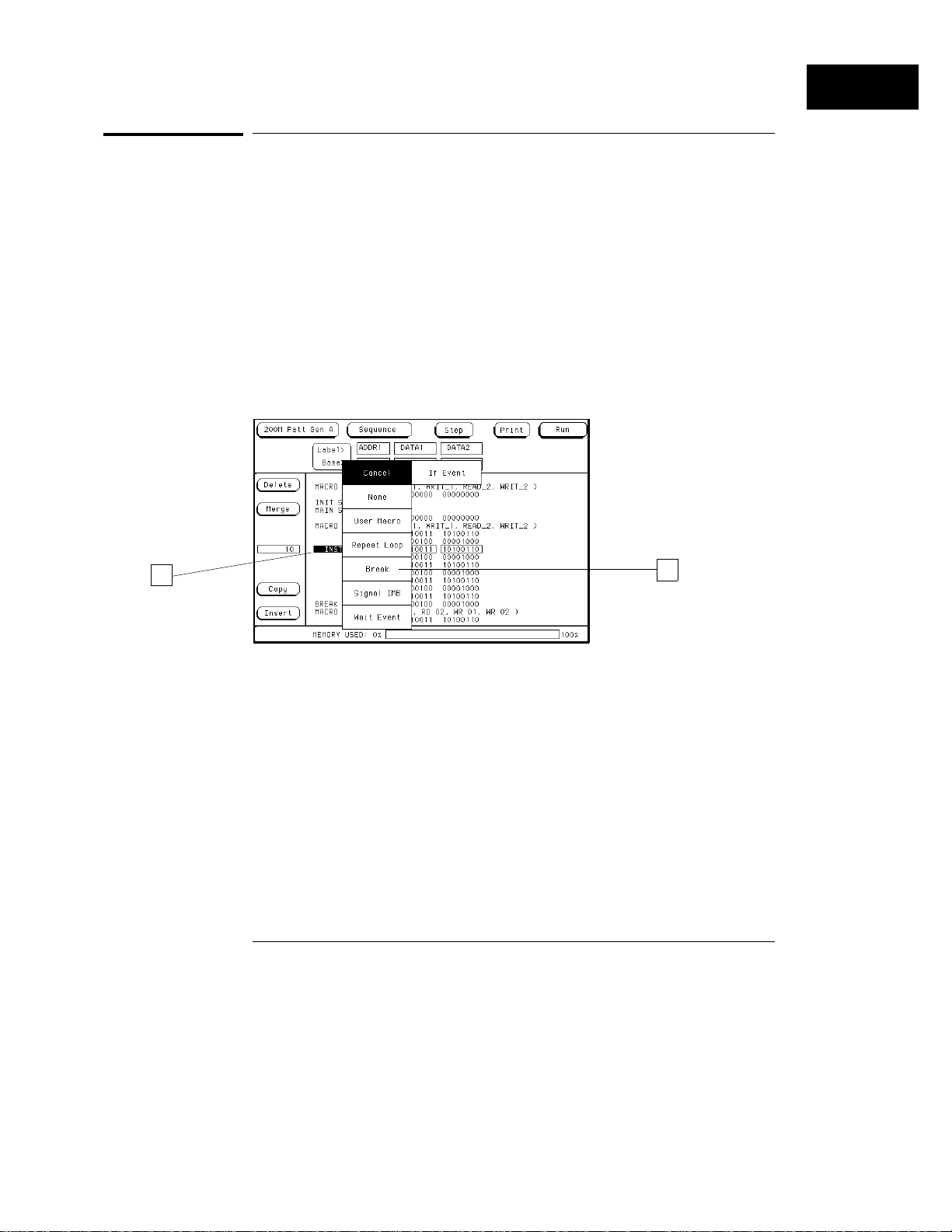
To include hardware instructions in a sequence
To include hardware instructions in a sequence
The following hardware instructions types are available:
Break
•
Signal IMB
•
Wait Event
•
If Event
•
1
Highlight the vector that you want output as a hardware instruction.
2
Select the INST field of the highlighted vector.
3
Select the desired hardware instruction type.
4
If required, select any qualifying actions for the hardware instruction.
2
3
1–9
Page 20
Using the
Agilent Technologies 16522A
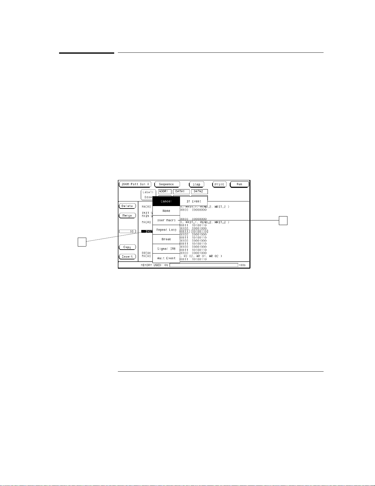
To include software instructions in a sequence
To include software instructions in a sequence
The following software instructions are available:
User Macro
•
Repeat Loop
•
If you are inserting a User Macro and have not yet built the macro, go to "To
build a user macro" later in this chapter. Macros must be built before they
can be inserted. To include these instructions in a sequence, use the
following procedure.
1
Highlight the vector that will be output at the time of the instruction.
2
Select the INST field.
3
Select the desired software instruction to insert.
4
If required, select any qualifying actions for the instruction.
3
2
1–10
Page 21
Using the
Agilent Technologies 16522A
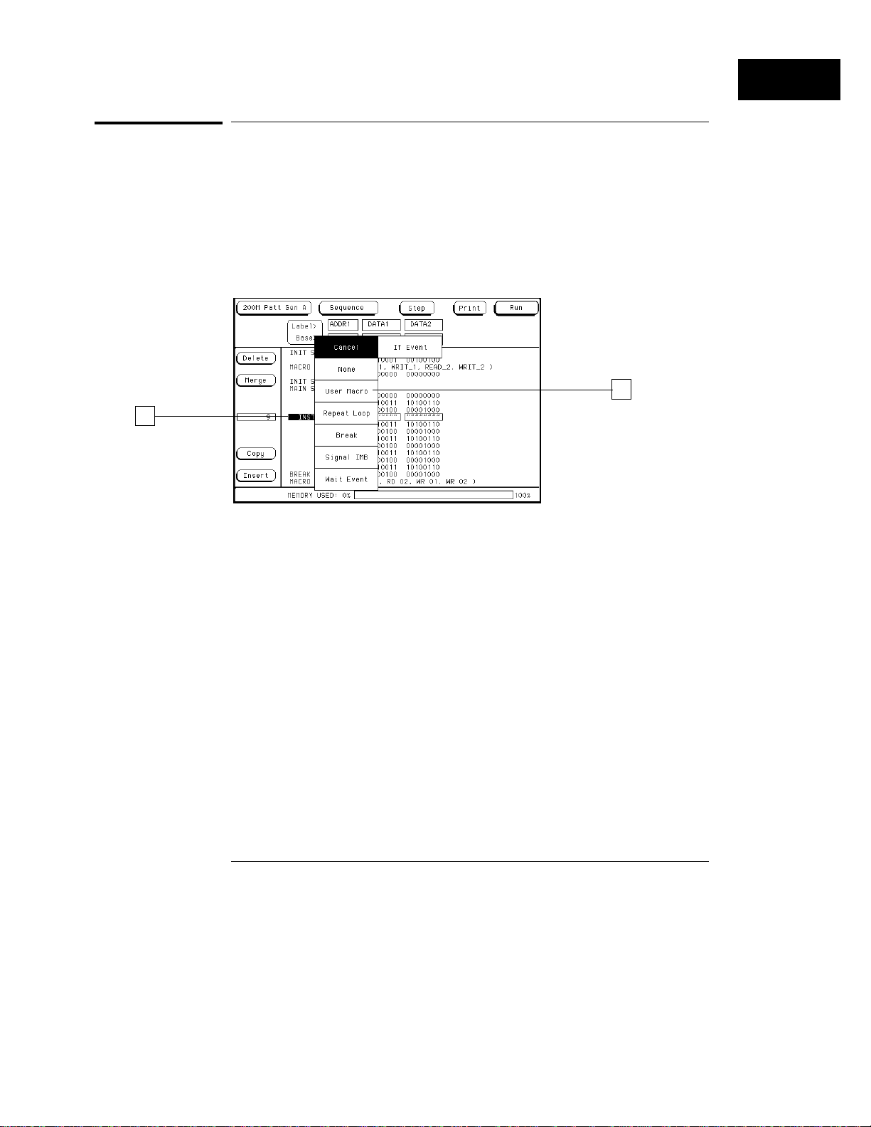
To include a user macro in a sequence
To include a user macro in a sequence
If you have user macros, you can include them in the vector sequence using
the following procedure. (If you have not yet built user macros, turn to the
module "To build a user macro" to build needed macros.)
1
Insert a new vector where you want to place the user macro.
2
Highlight this new vector using the knob, then select the INST field.
3
Select the User Macro field.
3
2
4
Select the user macro you want to insert from the list provided in the
pop-up.
1–11
Page 22
Using the
Agilent Technologies 16522A
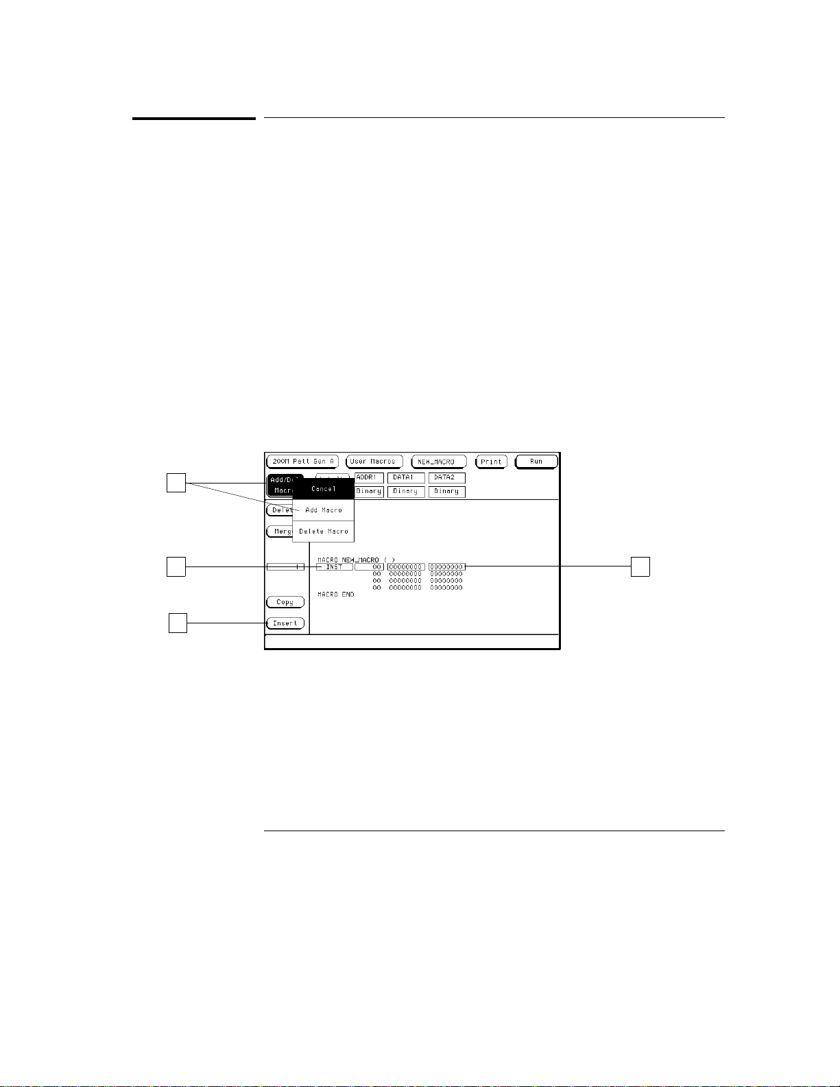
To build a user macro
To build a user macro
Build macros for sequences of vectors you will want to use in multiple places.
You can then insert these macros in INIT or MAIN sequences. Provide each
macro with a name that will help you identify its function and make it easier
to select from the list of macros you’ve built.
1
From the User Macros menu, select the Add/Del Macro field, then
select ADD MACRO.
2
Select the MACRO field, then type the new macro name.
3
Add any desired parameters.
Parameters are set when they are inserted into MAIN or INIT sequences. For
more information on adding parameters, refer to "Adding parameters" found
later in this chapter.
4
Select the Insert field to add as many vectors as needed into the
macro.
5
Highlight the desired vector to modify.
6
Highlight a data field and insert the appropriate data.
1
6 5
4
1–12
Page 23
2
Agilent Technologies 16522A
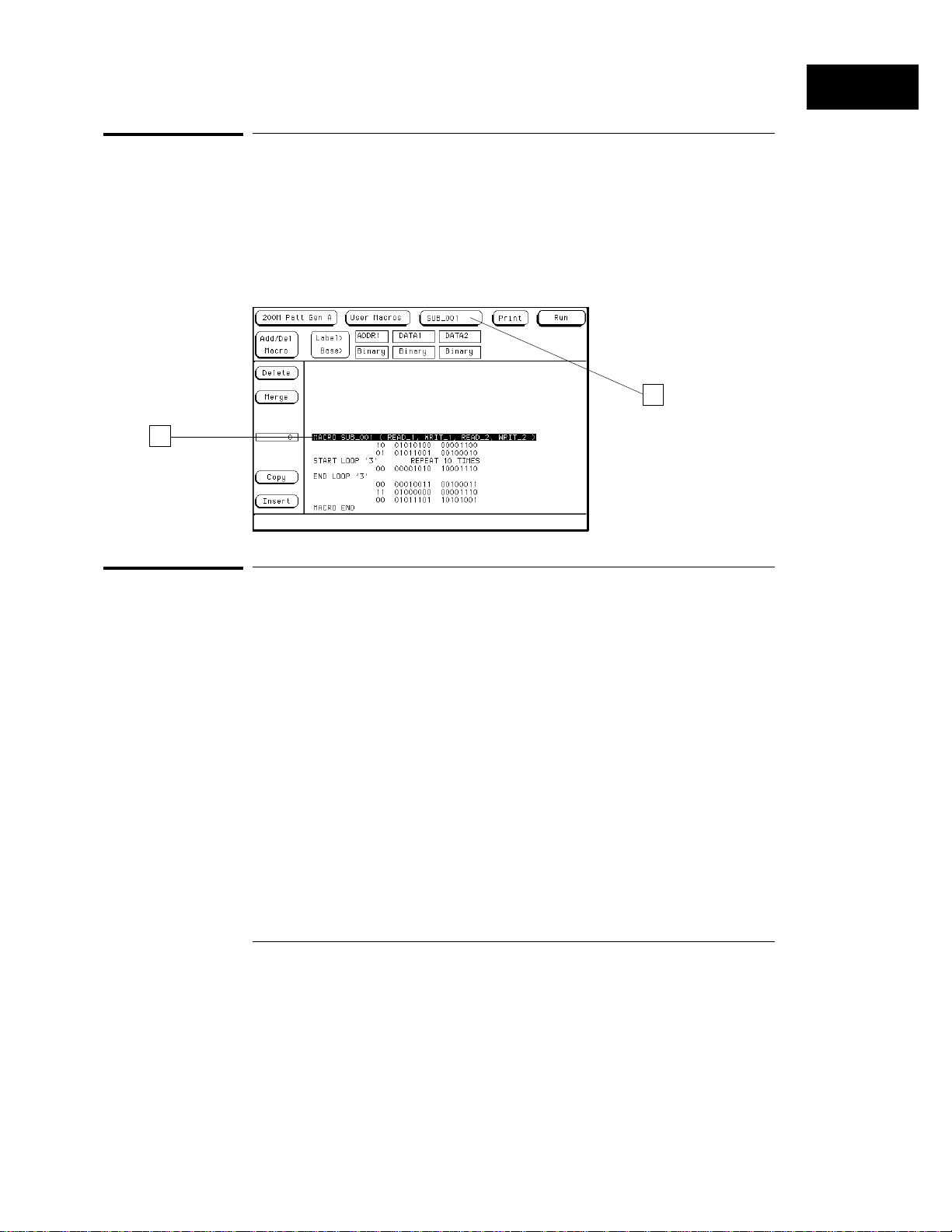
To modify a macro name
To modify a macro name
If you rename a macro, the new macro name will be displayed in INIT and
MAIN sequences where the macro has been used.
1
Select the macro to be renamed from the list of macros.
2
Highlight the first line of the macro, then select the field.
3
Modify the macro name, then select Done.
1
Using the
To edit a macro
1
Highlight the vector you want to edit using the knob.
2
Select the field you want to edit.
3
Select the new instruction or change the data values using the pop-up.
1–13
Page 24
Using the
Agilent Technologies 16522A
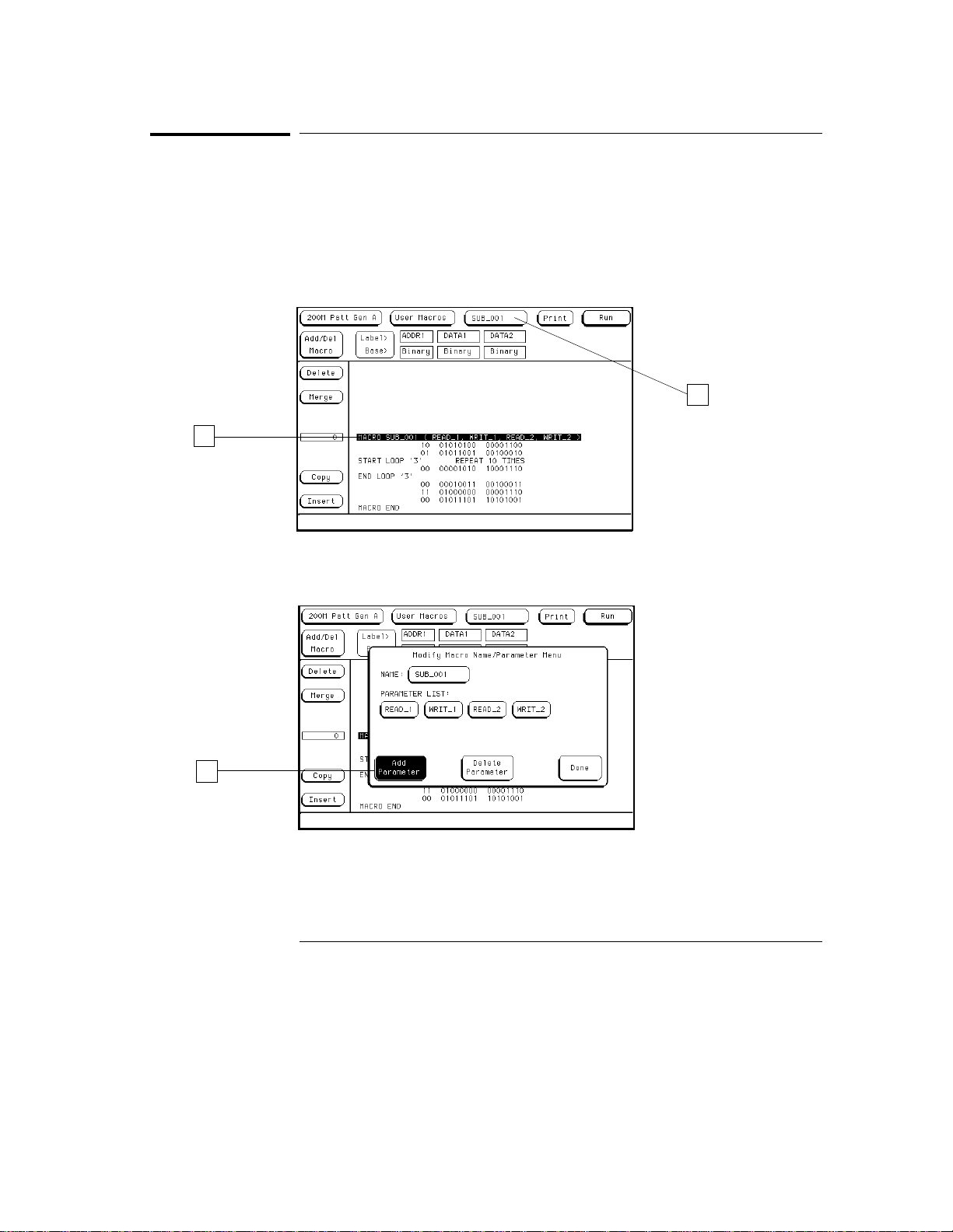
To add, delete, or rename parameters
To add, delete, or rename parameters
Parameters are set when they are inserted into MAIN or INIT sequences.
The changes you make in the parameter list will appear every place in the
INIT or MAIN sequences in which you have used that macro.
1
From the User Macros menu, select a macro from the list of macros.
2
Highlight the first line of the macro, then select the field.
1
2
3
3
To add a parameter, select Add Parameter, then select the new
parameter field that appears and rename the parameter.
4
To delete a parameter from the parameter list, select a parameter
name, then select Delete Parameter.
1–14
Page 25
Using the
Agilent Technologies 16522A
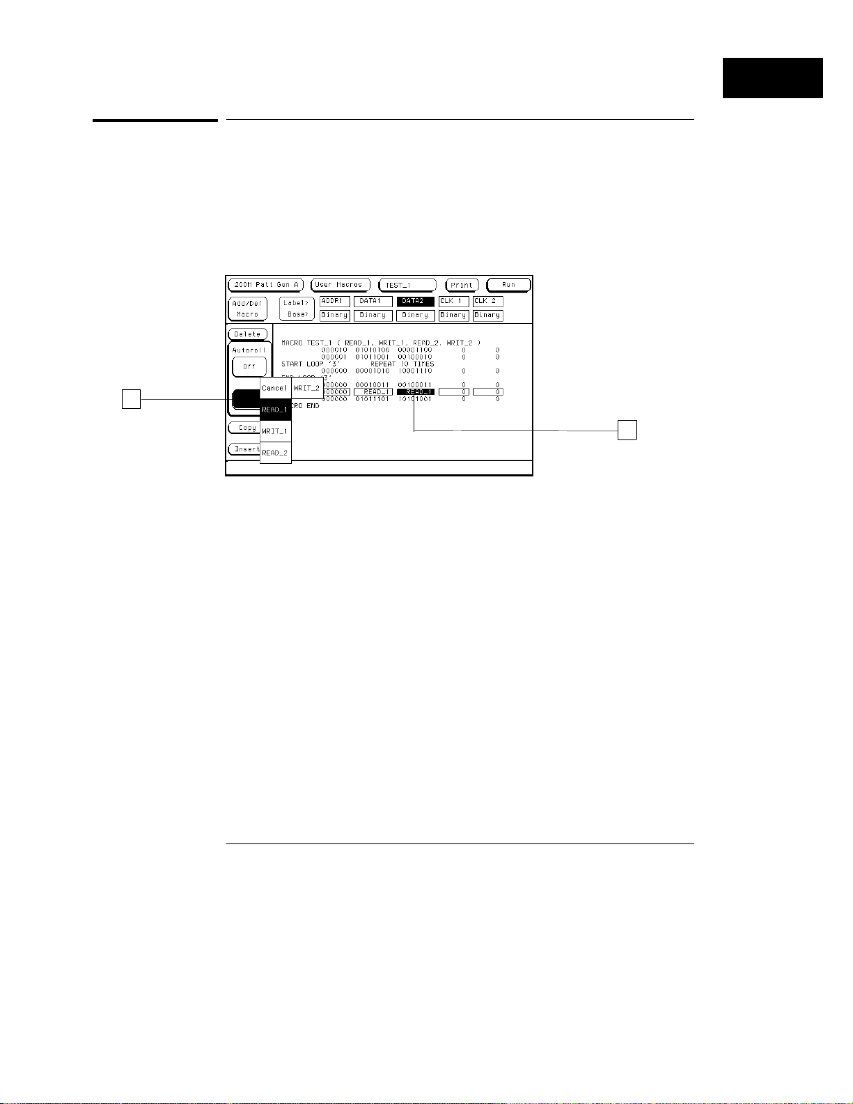
To place parameters in a vector
To place parameters in a vector
Once parameters are added to the parameter list, you insert them into data
fields in macro vectors.
1
From the User Macro menu, select the desired data field in a vector.
2
Select the Set Param field. From the parameter list that appears,
select the desired parameter to insert.
2
1
1–15
Page 26
1
Using the
Agilent Technologies 16522A
To enter or modify parameters
To enter or modify parameters
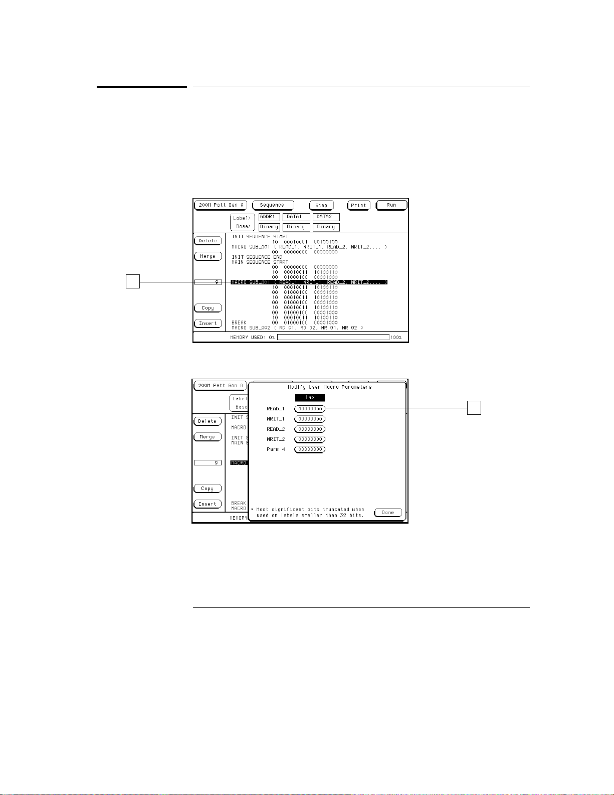
Each time you include a macro in an initialization or main sequence, you
should enter the parameters for that particular instance. To enter or modify
macro parameters, use the following procedure.
1
From the Sequence menu, highlight the line which contains the
macro name, then select the field.
2
Enter or modify the parameter in the pop-up menu.
3
Select Done.
1–16
2
Page 27
Using the
Agilent Technologies 16522A
To build a User Symbol Table
To build a User Symbol Table
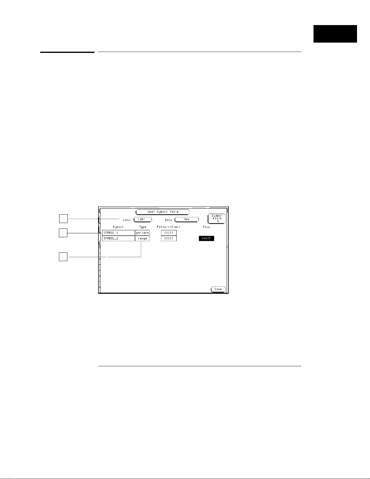
You may want to build a symbol table to make inserting values into your
program easier. You can name a symbol for one value in a label and insert
that symbol into your vector sequence where you need it.
1
From the Format menu select the Symbols field at the right of the
menu.
2
Set the desired Label, Base, and Symbol Width.
Symbols are specific for a given label. Symbol width determines the width of
the symbolic name displayed in the Sequence menu.
3
Select the Symbol field, then enter a name for the symbol.
4
Select the desired symbol Type, then enter the Pattern/Start and Stop
values.
The type is either a pattern or a range. A range provides a symbolic method
for defining values within a specified range.
5
If you want to add more symbols, select the Symbol field, then select
Add a Symbol, and repeat steps 2 through 4.
6
Select Done.
2
3
4
1–17
Page 28
Using the
Agilent Technologies 16522A
To include symbols in a sequence
To include symbols in a sequence
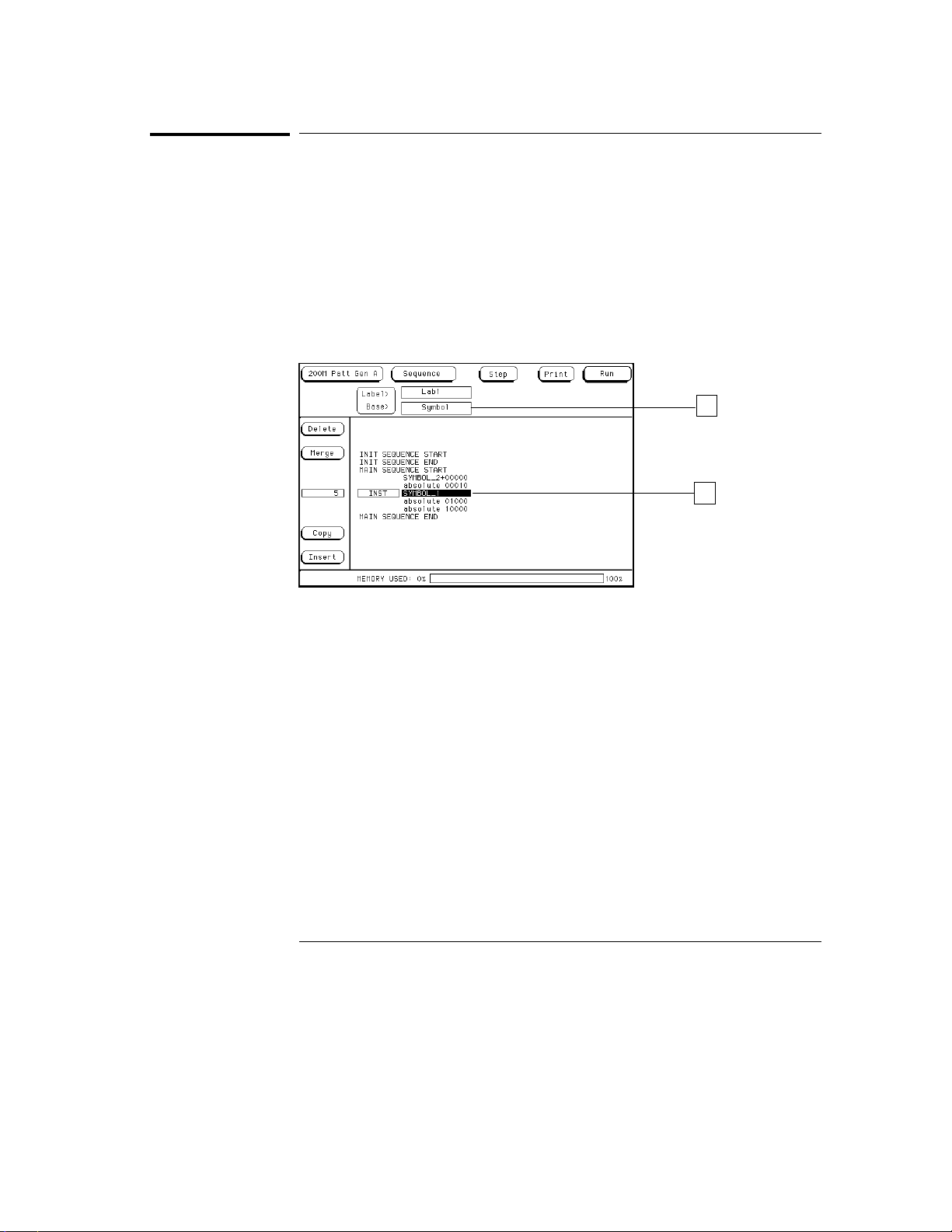
Symbols must be created before they become available for insertion. See the
task on the preceding page for more information.
1
From the Sequence menu, select the Base field under the desired
label where you want a symbol used.
2
From the Base selection list, select Symbol.
3
Highlight the desired vector, then select the data field.
4
Select the desired predefined symbol name.
2
3
1–18
Page 29
Agilent Technologies 16522A
To include symbols in a macro
To include symbols in a macro
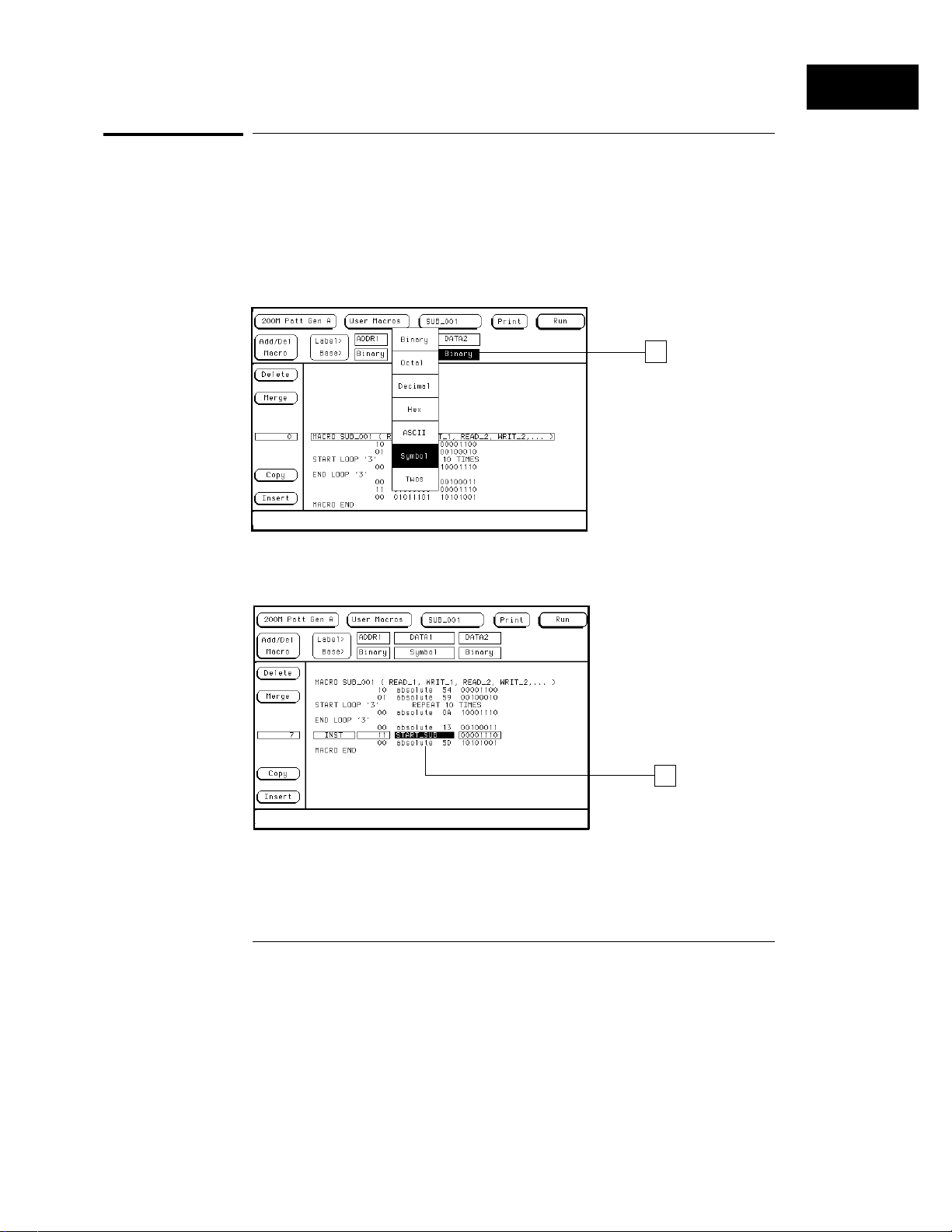
In the Format menu, you assign symbols to data under a given label. Once
assigned, these symbols can be included under the same label in a macro.
1
From the User Macros menu, select the label Base field for any label
you have preassigned symbols to. Then, select Symbol from the
Base selection list.
1
Using the
2
Highlight any vector in the macro. Then, select the data field under
the label that has the pre-assigned symbol.
2
3
Select the symbol name you want displayed.
1–19
Page 30
Using the
Agilent Technologies 16522A
To store a configuration
To store a configuration
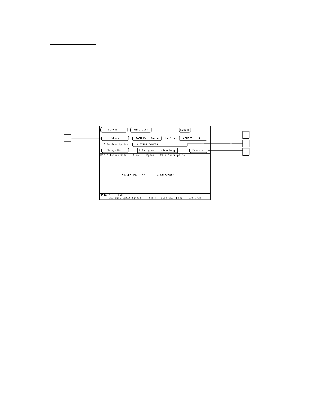
Once you have completed configuring the pattern generator, you can save
that configuration to hard disk for future uses.
1
Change to the System module.
2
Select Configuration, then Hard Disk.
3
Select the Store operation, then 200M Patt Gen.
4
Select the
5
Select the
6
Select Execute.
to file
field and type a name for the file.
file description
field and type in a description if desired.
3
4
5
6
1–20
Page 31
Using the
Agilent Technologies 16522A
To load a configuration
To load a configuration
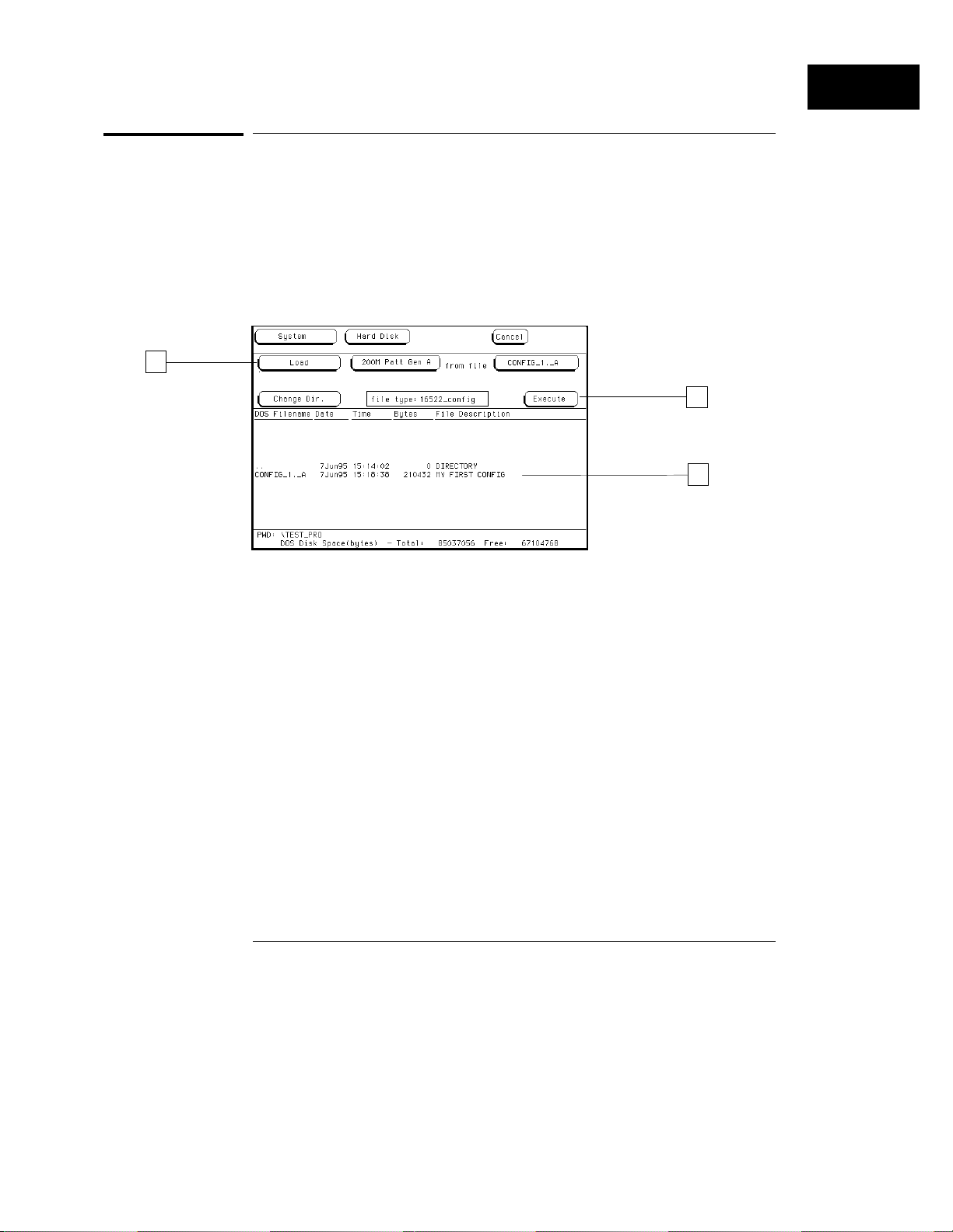
1
Change to the System module.
2
Select Configuration, then Hard Disk.
3
Select the Load operation, then 200M Patt Gen.
4
Highlight the file to be loaded with the knob.
5
Select Execute.
3
5
4
1–21
Page 32
Using the
Agilent Technologies 16522A
To use Autoroll
To use Autoroll
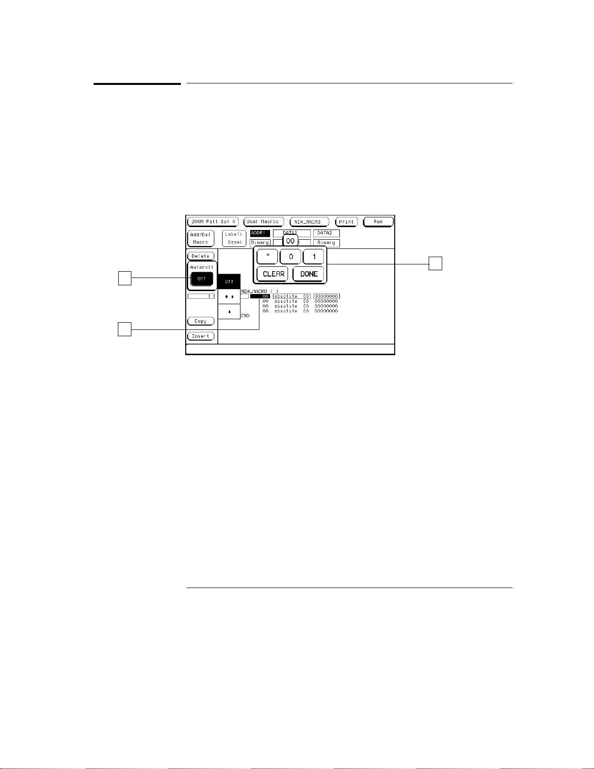
When Autoroll is used, each time you complete the process of adding data to
a data field, the data entry focus changes to the next specified data field.
The data entry keypad remains active, ready to define the next data field.
The following procedure shows you how to use Autoroll:
1
Select the first data field to define.
2
Enter the desired data using the pop-up keypad.
3
Select the Autoroll Off field, then select the desired roll direction.
2
3
1
4
As you continue to enter data and select Done, the data field focus
rolls to the next data field automatically.
1–22
Page 33

2
The Format Menu 2–3
The Sequence Menu 2–6
The User Macros Menu 2–14
Pod Numbering 2–16
Connecting Pods Directly to a PC Board 2–17
Output Pod Characteristics 2–18
Agilent Technologies 16522A Reference
Page 34

Agilent Technologies 16522A Reference
The Agilent Technologies 16522A is one in a family of modules that
plugs into the Agilent Technologies 16500B/C Logic Analysis System.
Many of the fields on the touch screen are identical to those on the
other modules. Therefore, this section provides information only on
those fields that are significantly different from the normal Agilent
16500B/C menu screens. This chapter provides reference information
about the following menu screens.
Format
•
Sequence
•
User Macros
•
For information about using the Agilent 16500B/C Logic Analysis
System, see the
System User’s Reference
Agilent Technologies 16500/16501A Logic Analysis
.
2–2
Page 35
Agilent Technologies 16522A Reference
The Format Menu
The Format Menu
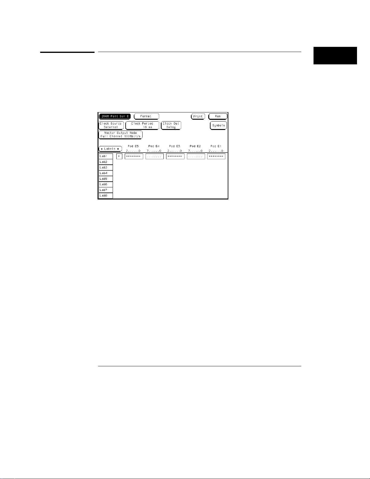
The Format menu allows you to configure the pattern generator with a clock
source and parameters, generate a symbol table, select its output mode,
assign which vector output channels are used, then group and label the
vector output channels. The initial Format menu is shown below.
Clock Source
The Clock Source field toggles between internal and external. The internal
clock source is supplied by the pattern generator and controls the frequency
the vectors are output to the system under test.
The external clock is provided by you, or the system under test, and is input
to the pattern generator through the CLK IN probe of a clock pod. By using
an external clock, you synchronize the vector output of the pattern generator
to the system under test.
No matter which clock is selected, vectors are output on the rising edge of
the clock.
2–3
Page 36

Agilent Technologies 16522A Reference
The Format Menu
Clock Period (internal clock source)
This field toggles from Clock Period, when an internal clock source is
selected, to Clock Frequency, when an external clock source is selected.
You select clock periods in steps of 1, 2, 2.5, 4, 5, 8, and 10. If the keypad is
used to select a value between the step intervals, the value is rounded to the
nearest interval.
The minimum clock period available with Vector Output Mode at Full
Channel 100Mbit/s is 10 ns. The minimum clock period available with Vector
Output Mode at Half Channel 200Mbit/s is 5 ns. Maximum clock period for
either mode is 250 µs.
Clock Frequency (external clock source)
This field toggles from Clock Frequency, when an external clock source is
selected, to Clock Period, when an internal clock source is selected. Set the
clock frequency range to match the frequency of the external clock source.
If the Vector Output Mode is Full Channel 100Mbit/s, you are offered two
clock frequency ranges:
Less than 50 MHz
•
Between 50 MHz and 100 MHz
•
If the Vector Output Mode is Half Channel 200Mbit/s, you are offered three
clock frequency ranges:
Less than 50 MHz
•
Between 50 MHz and 100 MHz
•
Greater than 100 MHz
•
If the external clock is faster than the frequency range selected, the
Agilent 16522A will produce erroneous output vectors.
Clock Out Delay
The Clock Out Delay setting allows you to position the output clock with
respect to data. The zero setting is uncalibrated and should be measured to
determine the initial position with respect to the data. Each numerical
change of one on the counter results in an approximate change of 1.3 ns.
2–4
Page 37

Agilent Technologies 16522A Reference
The Format Menu
Symbols
Touching the Symbols field brings up a pop-up menu that allows you to build
a symbol table to use when putting data into the Sequence and User Macros
menus. Providing symbol names to frequently used values allows you to
enter the values more easily and to recognize these values by their symbol
name rather than having to remember data values.
Vector Output Mode
The Vector Output Mode determines the channel width, available pods, and
the frequency range for both the internal and external clock. The following
table shows the difference between the Full Channel 100MBits/s mode and
the Half Channel 200MBits/s mode.
Full Channel
100 MBits/s
Pods Available Pods 1, 2, 3, 4, 5 Pods 1, 3, 5
Maximum Channels 40; eight per pod 20; eight on pods 1, 3
Maximum External Clock Frequency 100 MHz 200 MHz
Maximum Internal Clock Frequency 100 MHz 200 MHz
Minimum External Clock Frequency DC DC
Minimum Internal Clock Frequency 4 kHz 4 kHz
Half Channel
200 MBits/s
and lower 4 on pod 5
Labels
Labels allow the user to group output channels from the data pods into a
more logical configuration for creating vector data. The Agilent 16522A
labels work in the same fashion as the labels for the logic analyzer products,
with the exception that an output channel cannot be assigned to more than
one label. For more information on how to use labels, refer to "To build a
label" in chapter 1.
2–5
Page 38
Agilent Technologies 16522A Reference
The Sequence Menu
The Sequence Menu
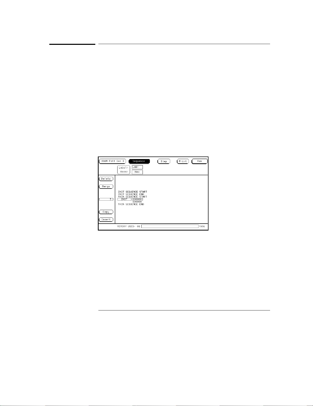
Use the Sequence menu to build your test vector files. The Agilent 16522A
provides for two sequences, an initialization sequence and a main sequence.
In single run mode the vectors are output from the first vector in the
initialization sequence to the last vector of the main sequence. The last
vector of the main sequence will be held at the outputs until run is executed
again.
In repetitive run mode the vectors in the initialization sequence will be
output from first to last one time, then the main sequence will repetitively
output the vectors in that sequence until the stop field is pressed. The vector
being output when stop is acknowledged by the module will be held at the
outputs until run is executed again.
The initialization sequence can be empty in which case it will be ignored.
The main sequence must contain at least two vectors to output. The
Sequence menu is shown below.
2–6
Page 39

Agilent Technologies 16522A Reference
The Sequence Menu
INIT and MAIN Sequences
Use the knob to highlight individual lines in either vector sequences. When a
line is highlighted, you can add data lines below it by selecting the Insert
field. Selecting the INST field brings up a dialog box that lets you insert one
of the instructions or user macros into the vector sequence.
An instruction is not allowed on the following vector lines of the sequence:
The first vector of the INIT sequence.
•
The first vector of the MAIN sequence.
•
The last vector of the MAIN sequence.
•
The vector prior to the IF block.
•
The first vector of the IF block.
•
The last vector of the IF block.
•
The vector following the IF block.
•
It should be noted that with the Vector Output Mode of Half Channel
200Mbit/s, the init sequence must contain a number of vectors that is
divisible by four. If this is not the case, the first vector of the init sequence is
duplicated to create the correct number of vectors.
With the Vector Output Mode of Full Channel 100 Mbit/s and vector
frequencies greater than 50 MHz, the init sequence must contain an even
number of vectors. Again if this is not the case, the first vector of the init
sequence is duplicated to create the correct number of vectors.
2–7
Page 40
Agilent Technologies 16522A Reference
The Sequence Menu
Step
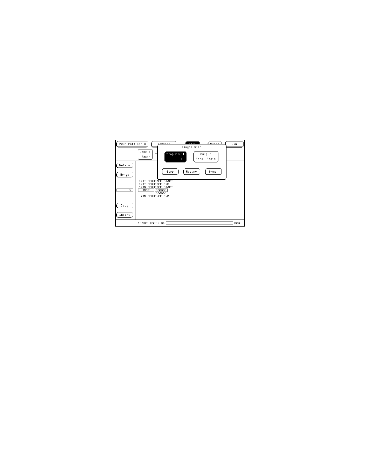
Use the Step field to step through your vector sequence to debug a critical
set of vectors following a break instruction in the program sequence.
Stepping will begin at the vector following the break instruction or the
Output First State item can be pressed which will place the first vector of the
sequence on the outputs. Stepping will then begin on the second vector of
the sequence. When the last vector of the main sequence is encountered
while stepping, the next step command places the first vector of the main
sequence on the outputs.
When stepping through a sequence, breaks are ignored while valid branch
and wait conditions are executed.
The Step Count field lets you set the number of steps to be executed, up to
100,000. The Output First State field reloads the hardware if necessary and
places the first vector of the sequence on the outputs. The Resume field
closes the Step pop-up menu and restarts the hardware without changing the
previous run mode. Execution resumes from the point at which the
sequence was stopped.
Delete
The Delete field lets you delete sequence lines. The From and To fields in
the Delete pop-up menu lets you select line numbers with either the knob or
another pop-up menu that appears when the From and To fields are touched
twice.
2–8
Page 41

Agilent Technologies 16522A Reference
The Sequence Menu
When deleting vector rows, the INIT START, INIT END, MAIN START, and
MAIN END cannot be deleted. Deleting all the vector rows from INIT START
to MAIN END will reset the sequence to the power up state. The delete will
not be performed if the results of the delete will place fewer than two vectors
in the main sequence, or, if the delete will place an instruction on any of the
following vectors:
The first vector of the INIT sequence.
•
The first vector of the MAIN sequence.
•
The last vector of the MAIN sequence.
•
The vector prior to the IF block.
•
The first vector of the IF block.
•
The last vector of the IF block.
•
The vector following the IF block.
•
Merge
Touching the Merge field brings up a pop-up menu that lets you select
sections of a previously created configuration file to merge after the current
line in the sequence. The Input Drive field selects between the hard disk or
the front floppy disk (if present). The Filename field displays a file browser
pop-up menu that allows searching for the file to be used in the merge. The
Merge Section field allows selection of the section of the configuration to be
merged. Configuration sections are the main sequence and any macros that
were created. The merge will not be performed in the following cases:
Merge data exceeds the maximum number of sequence lines.
•
Merge data requires more repeats than are available.
•
Merge data requires more macro calls than are available.
•
2–9
Page 42

Agilent Technologies 16522A Reference
The Sequence Menu
Merge is not allowed in the following cases:
Within a repeat loop.
•
Within an IF block (starting with the vector prior to the if and ending with
•
the vector following the IF).
Between the start and first vector of the main sequence.
•
After the last vector of the main sequence.
•
Between the init and main sequence.
•
Between the start and first vector of the init sequence.
•
Within an empty init sequence (insert one vector in the init and merge
•
after that vector).
Copy
Selecting the Copy field brings up a pop-up menu that lets you select vector
sequence lines to be copied and a location to insert them after. The values in
the Start, End, and Copy After fields can be selected with the knob or with
the pop-up keypad that appears when the appropriate field is touched twice.
Copy will not be performed if you run out of macro calls (1000) or repeats
(1000). Copy will not be allowed if the result of the copy places an
instruction on one of the following vectors:
The first vector of the INIT sequence.
•
The first vector of the MAIN sequence.
•
The last vector of the MAIN sequence.
•
The vector prior to the IF block.
•
The first vector of the IF block.
•
The last vector of the IF block.
•
The vector following the IF block.
•
Insert
Touching the Insert field adds another instruction line immediately below the
line that is currently selected.
2–10
Page 43

Agilent Technologies 16522A Reference
The Sequence Menu
Instructions
User Macro
user macros you can insert. Macros are inserted at the current line and
expanded at run time.
If the macro selected has parameters, a second pop-up menu will be
displayed to allow setting of the passed parameter values. Parameters are
passed as 32 bit values and the most significant bits are truncated when the
data is applied to labels with less than 32 bits.
Once inserted, the passed parameters of a macro may be altered by selecting
that macro again and changing the data. A macro can only be removed from
the sequence by using the delete field.
The User Macro instruction brings up a list of current
Repeat Loop
repeat loop using the current vector row as the data. Once the loop has
been created, vectors can be inserted or copied into the loop to change
the size. A repeat loop will be expanded at run time into individual
vectors. The number of repetitions of the loop (maximum 20000) is set
when the repeat is first inserted into the sequence and can be altered by
selecting the start of the repeat to get the Repeat Count pop-up menu.
Both the start and end of a repeat loop will be removed from the
sequence if either is included in the delete block.
Break
single run mode, this instruction halts the sequence and holds the
outputs at the break vector’s value. In repetitive run mode, this
instruction pauses the sequence at the current vector momentarily, then
continues. The duration of the pause is dependent on the activity of
other modules in the frame.
Signal IMB
of the 16500B/C at the current vector, allowing the Agilent 16522A to
trigger other modules in the frame. Multiple signal IMB instructions may
be placed in the sequence, but only the first signal IMB will be executed.
The Break instruction causes a break at the current vector. In
The Repeat Loop instruction inserts the start and end of a
The Signal IMB instruction creates a signal for the IMB bus
2–11
Page 44

Agilent Technologies 16522A Reference
The Sequence Menu
Wait Event
program sequence until the event is received by the hardware. Selecting
this instruction brings up a pop-up menu that allows you to set four data
patterns and select one of them or an IMB signal as the event the pattern
generator is waiting for.
An external wait event is the ORing of the three input lines on the clock pod.
The first wait IMB is the only one recognized since IMB does not allow
pulsing.
If Event
Mbit/s mode with clock frequencies of 50 MHz and lower. Only one If
Event is allowed in a sequence program. If a new if instruction is placed
in a program sequence, a message will appear stating that only one if
instruction is allowed. To add a new if instruction, the old one must be
deleted.
The If event uses either the IMB or the same external clock pod input lines as
the Wait event. If the condition is true at the If event, then the data in the If
block is output, otherwise it is skipped.
The If event takes the current data line and duplicates as in the following
example:
current data
current data
These vectors are now restricted. They cannot have instructions. Delete and
Copy operations that result in instructions being placed on these vectors will
not be allowed. The If can be removed by deleting either the start or end of
the If block.
It should be noted that when an If statement is in the sequence, repetitive
runs of the sequence have latency between the last and the first vectors of
the main sequence. This latency is dependent on the activity of other
modules in the frame, thus varying from run to run.
The Wait Event instruction halts the execution of the
The If Event instruction is only available in Full Channel 100
IF
current data
current data
END IF
2–12
Page 45
Agilent Technologies 16522A Reference
The Sequence Menu
Data Field
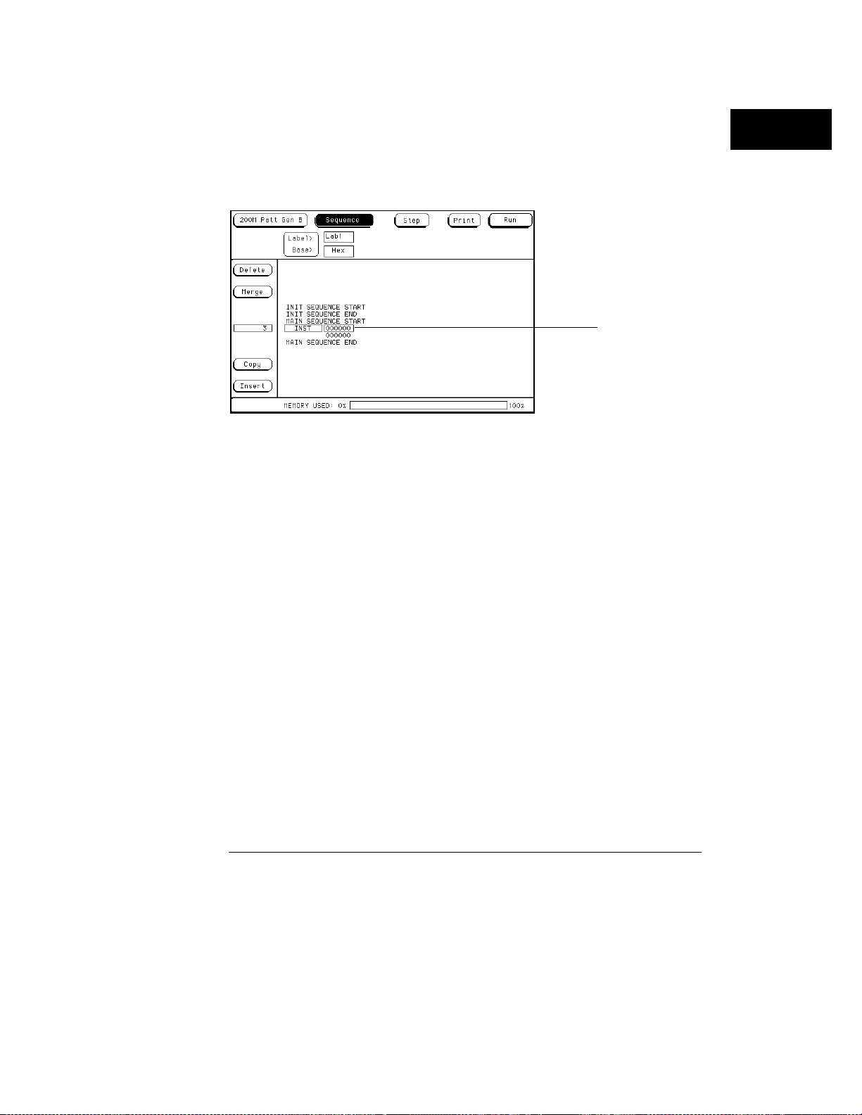
Selecting the data field to the right of the instruction field brings up a pop-up
menu that allows you to insert vector data. ASCII-based data cannot be
edited, and ASCII- and Symbols-based data cannot be autorolled.
Data Field
Autoroll
The Autoroll field is provided to reduce the number of keystrokes required to
enter data into the sequence or a macro. When a data field is edited (except
in the last vector row), the Autoroll field appears to the left of the data entry
pop-up menu. Autoroll can move from left to right across the labels on the
display with an automatic line feed, or it can move down a label from vector
row to row. When the last vector row of the sequence is encountered,
Autoroll will stop the editing process, or the Autoroll can be halted at any
point in the editing process by turning the autoroll function off.
For more information on how to use the Autoroll, refer to "To use Autoroll" in
chapter 1.
MEMORY USED
The Memory Used bar shows in percent how much memory is being used by
the vector sequence entered. It should be noted that Repeat Loops and User
Macros may suddenly increase the amount of memory used because they are
expanded at run time. It is critical to use the Memory Used bar to obtain an
idea of how much memory will be needed at run time.
2–13
Page 46
Agilent Technologies 16522A Reference
The User Macros Menu
The User Macros Menu
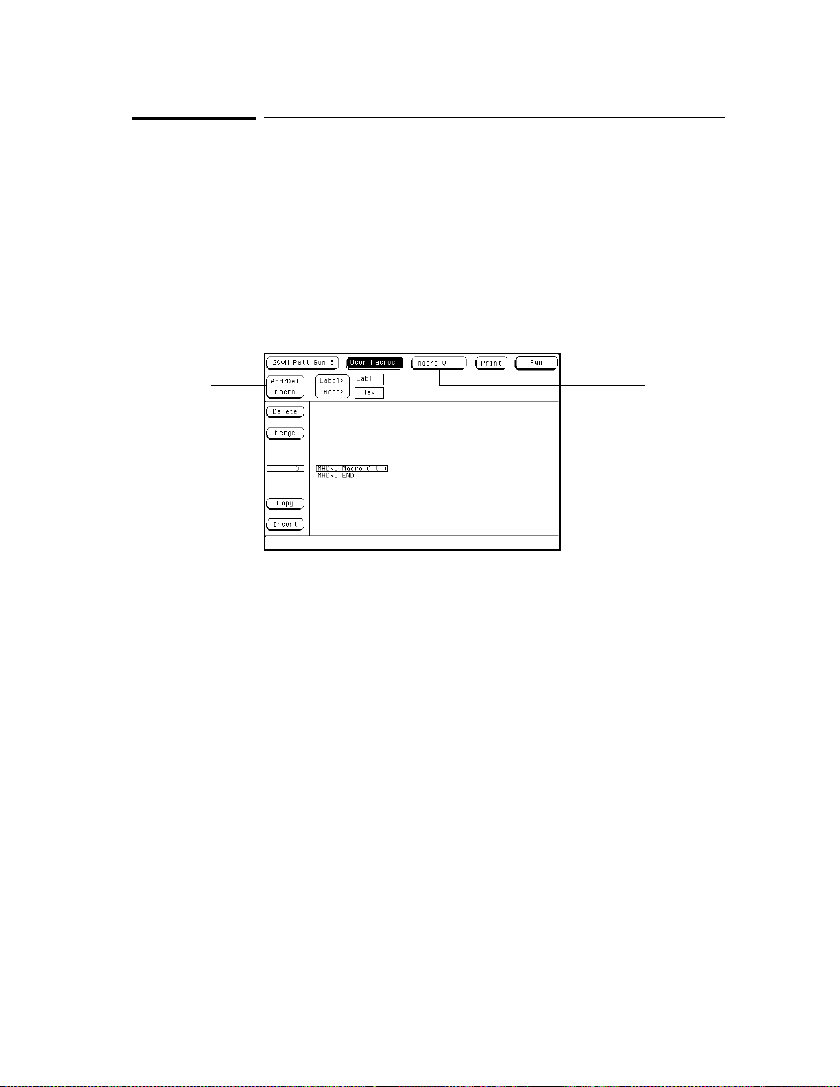
The User Macros menu is used to create new macros and edit existing
macros. Macro 0 is the default macro and always exists. Macros enable you
to define a pattern sequence once, then insert the macro by name wherever
it is needed.
Macros can also have parameters passed to them. Parameters let you create
a generic macro. For each instance of a macro, you specify unique values for
the parameterized variable. Each macro can have up to 10 parameters. Up
to 100 different macros can be defined for use in a single stimulus program.
Differences between User Macros and the INIT and MAIN sequences are that
macros cannot use the If instruction and a macro cannot call another macro.
Add/Del
Macro
Current Macro
This section only covers the two unique fields in the User Macros menu and
using parameters. For information about other fields in this menu, refer to
the discussion of these fields in the previous section on the Sequence Menu.
Macro 0 (current macro field)
Touching this field brings up a list of macros that have been created and are
available to insert into the Sequence menu. If you want to edit a previously
built macro or to view it, select that macro from the list and it will appear in
the main part of the display.
2–14
Page 47

Agilent Technologies 16522A Reference
The User Macros Menu
Add/Delete Macro
Selecting this field brings up a pop-up menu that allows you to choose
between adding a new macro or deleting one. If you select Add Macro, a new
blank macro appears in the display with a new Macro "n" name.
To rename the new macro, select the macro name field, and in the pop-up
menu that appears, type in a new name. You can also add parameters to the
new macro in the same pop-up menu. For more information on parameters,
refer to "Using Parameters" below.
If you select Delete Macro, you will be presented with a list of current
macros. Select the macro you want to delete from the list. If the macro you
delete is being used in the MAIN sequence, it will be removed from the
sequence. If you try to delete the first macro, it will be removed from the
MAIN sequence but not from the macro list.
Using Parameters
Parameters are used to pass values into macros. A major benefit in passing
parameters is that you keep a macro’s functionality generic and still direct
specific action identified by parameters. Think of parameters as the only part
of a macro that changes as the macro is reused.
You create the macro and add parameters to the macro in the User Macro
menu. You then insert the macro and assign parameter values in the
Sequence menu. As you reuse the macro in other places in the sequence,
simply change parameter values to the new specific values.
Macro parameters are passed as 32 bit values. If fewer than 32 bits are
assigned to a label in the Format menu, the most significant bits of the
parameter value are truncated when the parameter is used as data for the
given label.
For more information on using macros and parameters, refer to chapter 1.
2–15
Page 48
Agilent Technologies 16522A Reference
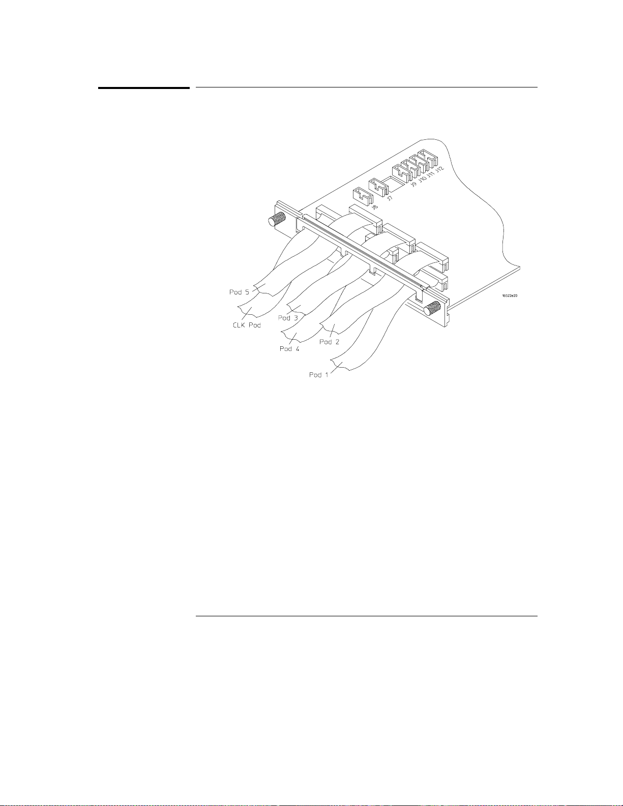
Pod Numbering
Pod Numbering
The Agilent 16522A pods are numbered as shown in the figure below.
2–16
Page 49
Agilent Technologies 16522A Reference
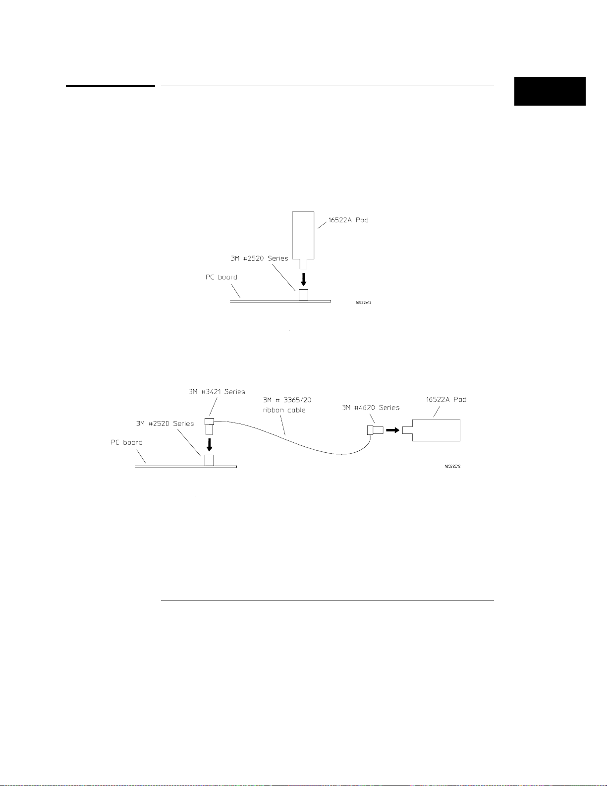
Connecting Pods Directly to a PC Board
Connecting Pods Directly to a PC Board
To connect the pattern generator pods directly to the PC board, use one of
the following two methods. Both methods require a 3M 2520-series, or
similar alternative connector be installed on the PC board.
Direct pod to board connection
Simply plug the pod directly into the 3M 2520-series, or similar alternative
connector on the PC board.
Jumper cable to pod connection
Use this method when you have clearance problems on the PC board.
Construct a flat ribbon cable and connect as shown below.
Equivalent connectors can be obtained from sources other than 3M.
2–17
Page 50
Agilent Technologies 16522A Reference
Output Pod Characteristics
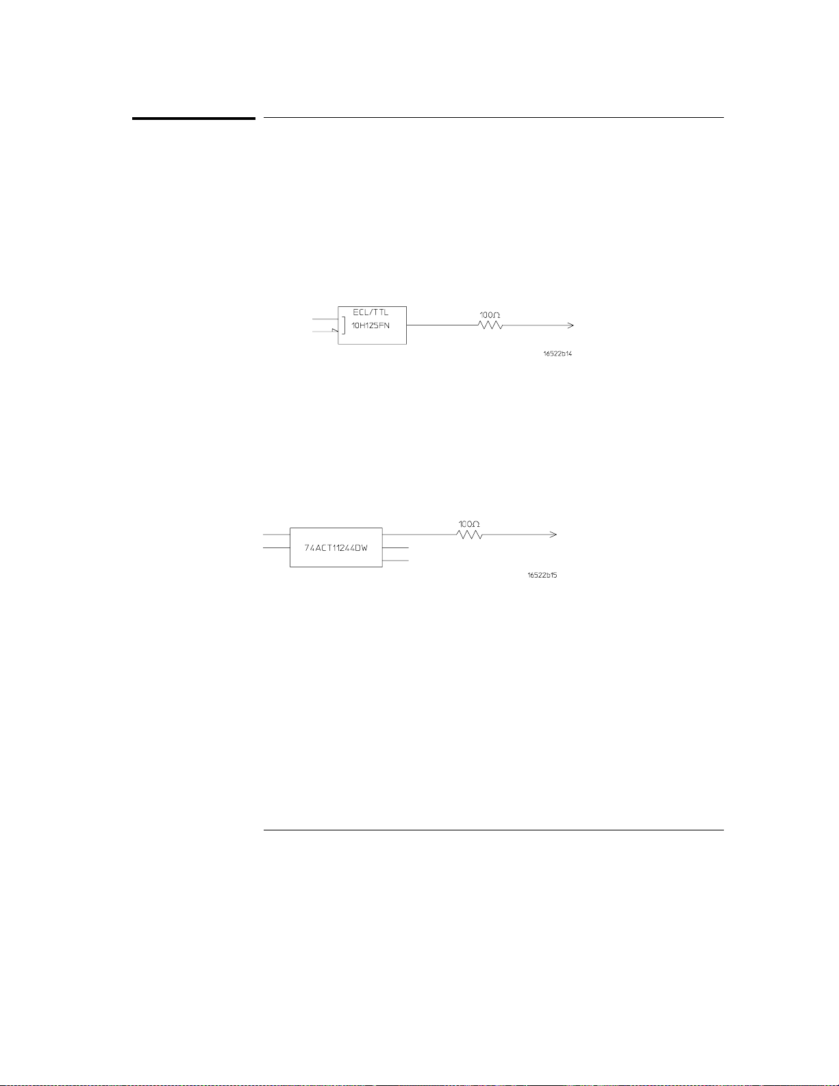
Output Pod Characteristics
The following equivalent circuit information is provided to help you select the
appropriate clock and data pods for your application.
Agilent 10461A TTL Data Pod
Output type 10H125 with 100 ohm in series
Maximum clock 200 MHz
Skew Typical <2 ns; worst case 4 ns (note 1)
Recommended lead set Agilent 10474A
Agilent 10462A 3-State TTL/CMOS Data Pod
Output type 74ACT11244 with 100 ohm in series
10H125 on non 3-state channel 7 (note 2),
3-state enable negative true, 100K ohm to GND,
enabled on no connect
Maximum clock 100 MHz
Skew Typical <4 ns; worst case 12 ns (note 1)
Recommended lead set Agilent 10474A
2–18
Page 51
Agilent Technologies 16522A Reference
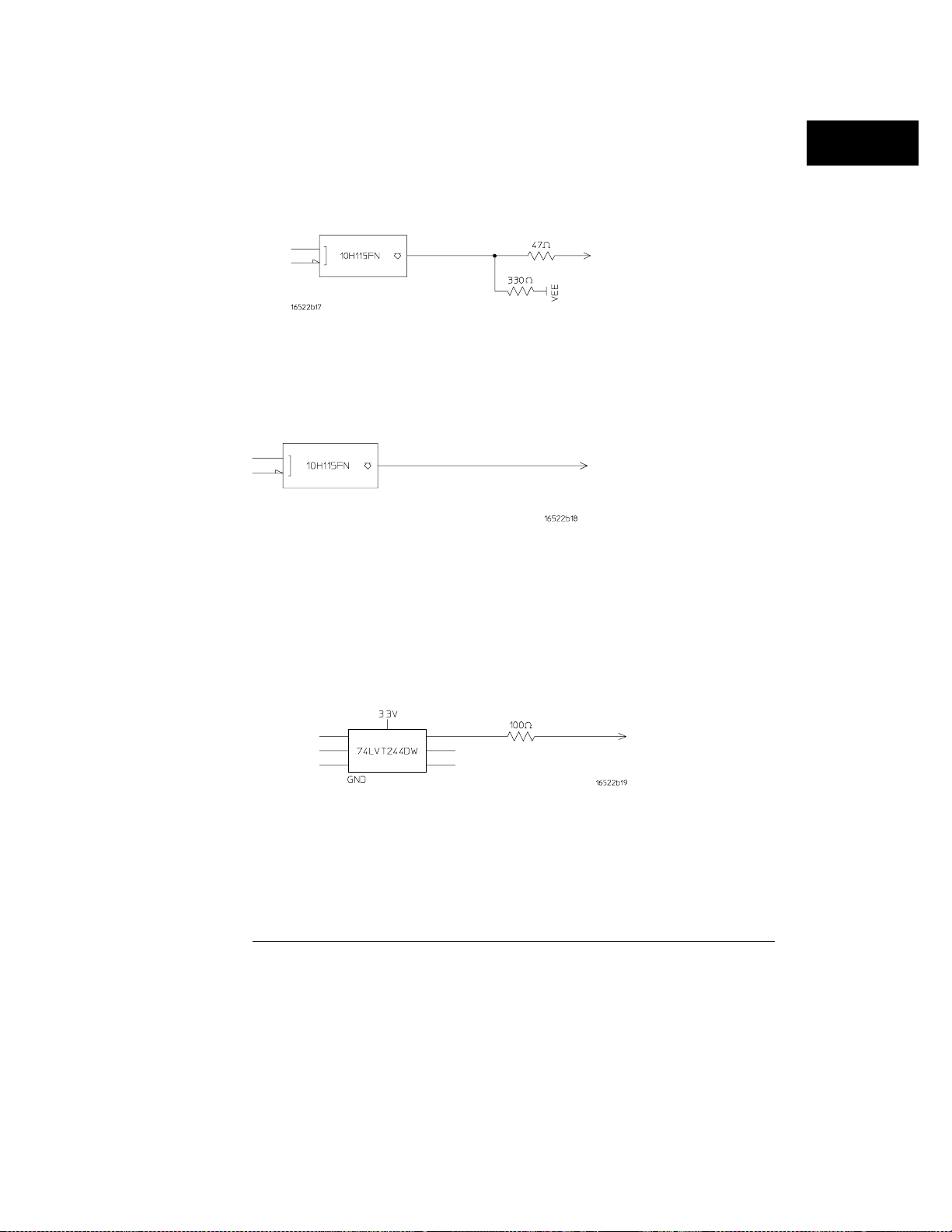
Output Pod Characteristics
Agilent 10464A ECL Data Pod (terminated)
Output type 10H115 with 330 ohm pulldown, 47 ohm in series
Maximum clock 200 MHz
Skew Typical <1 ns; worst case 2 ns (note 1)
Recommended lead set Agilent 10474A
Agilent 10465A ECL Data Pod (unterminated)
Output type 10H115 (no termination)
Maximum clock 200 MHz
Skew Typical <1 ns; worst case 2 ns (note 1)
Recommended lead set Agilent 10347A
Agilent 10466A 3-State TTL/3.3 Volt Data Pod
Output type 74LVT244 with 100 ohm in series
10H125 on non 3-state channel 7 (note 2)
3-state enable negative true, 100K ohm to GND,
enabled on no connect
Maximum clock 200 MHz
Skew Typical <3 ns; worst case 7 ns (note 1)
Recommended lead set Agilent 10474A
2–19
Page 52
Agilent Technologies 16522A Reference
Output Pod Characteristics
Note 1
Note 2
Typical skew measurements made at pod connector with approximately
10 pF/50K ohm load to GND; worst case skew numbers are a calculation of
worst case conditions through circuits. Both numbers apply to any channel
within a single-card or multiple-card module.
Channel 7 on the 3-state pods has been brought out in parallel as a non
3-state signal. By looping this output back into the 3-state enable line, the
channel can be used as a 3-state enable.
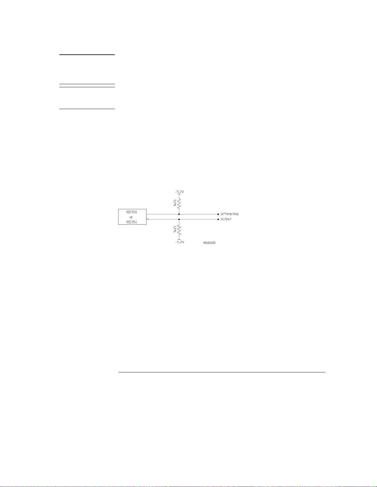
Data Cable Characteristics Without a Data Pod
The Agilent 16522A data cables without a data pod provide an
ECL-terminated
(1 KΩ to -5.2 V) differential signal. These are usable when received by a
differential receiver, preferably with a 100 ohm termination across the lines.
These signals should not be used single ended due to the slow fall time and
shifted voltage threshold (they are not ECL compatible).
2–20
Page 53
Agilent Technologies 16522A Reference
Output Pod Characteristics
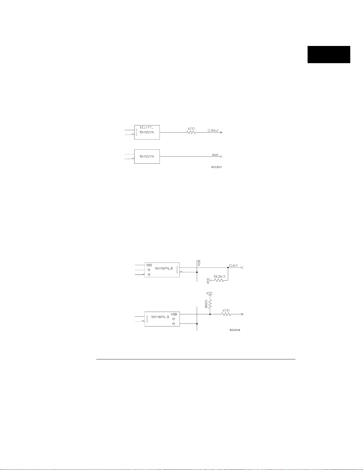
Agilent 10460A TTL Clock Pod
Clock output type 10H125 with 47 ohm series; true & inverted
Clock output rate 100 MHz maximum
Clock out delay 11 ns maximum in 9 steps
Clock input type TTL - 10H124
Clock input rate DC to 100 MHz
Pattern input type TTL - 10H124 (no connect is logic 1)
Clk-in to clk-out Approx. 30 ns
Patt-in to recognition Approx. 15 ns + 1 clk period
Recommended lead set Agilent 10474A
Agilent 10463A ECL Clock Pod
Clock output type 10H116 differential unterminated; and differential
with 330 ohm to -5.2v and 47 ohm series
Clock output rate 200 MHz maximum
Clock out delay 11 ns maximum in 9 steps
Clock input type ECL - 10H116 with 50 KΩ to -5.2 V
Clock input rate DC to 200 MHz
Pattern input type ECL - 10H116 with 50 KΩ (no connect is logic 0)
Clk-in to clk-out Approx. 30 ns
Patt-in to recognition Approx. 15 ns + 1 clk period
Recommended lead set Agilent 10474A
2–21
Page 54

2–22
Page 55

3
Programming the Agilent 16522A 3–2
Programming Overview 3–3
Example Pattern Generator Program 3–3
Selecting the Module 3–4
Mainframe Commands 3–5
Command Set Organization 3–8
Module Status Reporting 3–10
Module Level Commands 3–13
FORMat Subsystem 3–17
SEQuence Subsystem 3–24
MACRo Subsystem 3–36
SYMBol Subsystem 3–48
Data and Setup Commands 3–55
Programming the Agilent 16522A
Page 56

Programming the Agilent 16522A
This chapter, combined with the
Guide
the
Agilent 16522A pattern generator module. Each module has its own
manual to supplement the mainframe manual since not all mainframes
will be configured with the same modules.
This chapter is organized into seven sections. The first section
discusses:
•
•
•
•
The next section contains the module level commands and the
following four sections contain the subsystem commands for the
pattern generator. The final section contains information on the
SYSTem:DATA and SYSTem:SETup commands for this module.
Error messages for the Agilent 16522A are included in generic system
error messages and are in the
manual, provides you with the information needed to program
Programming overview and instructions to help you get started
Mainframe system commands that are frequently used with the
pattern generator module
Agilent 16522A Pattern Generator command tree
Alphabetic command-to-subsystem directory
Agilent 16500 Programmer’s
Agilent 16500 Programmer’s Guide
.
Programming commands are derived from front panel operation.
These operations are described in detail in chapter 2. You should be
familiar with the front panel operations before attempting to program
the pattern generator.
3–2
Page 57

Programming Overview
This section introduces you to the basic command structure used to
program the pattern generator.
Example Pattern Generator Program
A typical pattern generator program includes the following tasks:
select the appropriate module
•
set program parameters
•
define a pattern generator program
•
run the pattern generator program
•
The following example program generates a pattern using two of the output
pods of the master card:
10 OUTPUT XXX;":SELECT 1"
20 OUTPUT XXX;":FORMAT:REMOVE ALL"
30 OUTPUT XXX;":FORMAT:LABEL ’A’,POSITIVE,127,0"
40 OUTPUT XXX;":FORMAT:LABEL ’B’,POSITIVE,0,255"
50 OUTPUT XXX;":SEQ:REMOVE ALL"
60 OUTPUT XXX;":SEQ:INSERT 0,NOOP,’#H7F’,’#HFF’"
70 OUTPUT XXX;":SEQ:INSERT 4,NOOP,’#H7F’,’#HFF’"
80 OUTPUT XXX;":RMODE REPETITIVE"
90 OUTPUT XXX;":START"
100 END
The three Xs (XXX) after the OUTPUT statement in the above example refer to
the device address required for programming over either GPIB or RS-232-C.
Refer to your controller manual and programming language reference manual
for information on initializing the interface.
3–3
Page 58

Programming the Agilent 16522A
Selecting the Module
Program Comments
Line 10 selects the pattern generator in slot A
Line 20 removes all labels previously assigned
Line 30 assigns label ’A’, positive polarity and assigns the seven least
significant bits of pod A5
Line 40 assigns label ’B’ and assigns all eight bits of pod A4
Line 50 removes all program lines
Line 60 inserts a new line (after line 0) in the INIT SEQUENCE portion of the
program.
Line 70 inserts a new line (after line 4) in the MAIN SEQUENCE portion of
the program. Recall that the default MAIN SEQUENCE already has two lines
of program
Line 80 Sets the RMODE to repetitive. If the program is to be run only once,
select the :RMODE SINGLE command.
Line 90 Starts the program.
Selecting the Module
Before you can program the pattern generator, you must first "select" it,
otherwise, there is no way to direct your commands to the pattern generator.
To select the module, use the system command :SELect , followed by the
numeric reference for the slot location of the pattern generator(1...10 refers
to slot A...J respectively). For example, if the pattern generator master card
is in slot E, then the command:
:SELect 5
would select this module. For more information on the SELect command,
refer to the
Agilent 16500 Programmer’s Guide
.
3–4
Page 59

Programming the Agilent 16522A
Mainframe Commands
Mainframe Commands
These commands are part of the Agilent 16500B/C mainframe system and are
mentioned here only for reference. For more information on these
commands, refer to the
Agilent 16500 Programmer’s Guide
.
Query
Example
CARDcage?
The CARDcage query returns a string which identifies the modules that are
installed in the mainframe. The returned string is in two parts. The first five
two-digit numbers identify the card type. The identification number for the
pattern generator master is 25, while the pattern generator expander uses 24.
A "-1" in the first part of the string indicates no card is installed in the slot.
The five single-digit numbers in the second part of the string indicate in
which slots cards are installed and where the master card is located.
13,13,-1,-1,25,1,1,0,0,5
A returned string of 13,13,-1,-1,25,1,1,0,0,5 means that an oscilloscope is
loaded in slot A and slot B. The next two slots (C and D) are empty (-1).
Slot E contains a pattern generator module (ID number 25).
The next group of numbers (1,1,0,0,5) indicate that a two card module is
installed in slots A and B with the master card in slot A. The "0" indicates an
empty slot or the module software is not recognized or not loaded. The last
digit (5) in this group indicates a single module card is loaded in slot E.
Complete information for the CARDcage query is in the
Programmer’s Guide
.
Agilent 16500
3–5
Page 60

Programming the Agilent 16522A
Mainframe Commands
Subsystem
Subsystem
Command/Query
INTerm odule Subsystem
The INTermodule Subsystem commands are used to specify intermodule
arming between multiple modules.
MMEMory
The MMEMory Subsystem provides access to both disk drives for loading and
storing configurations.
MENU
The MENU command selects a new displayed menu. The first parameter (X)
specifies the desired module. The optional second parameter specifies the
desired menu in the module (defaults to 0 if not specified). The query
returns the currently selected (and displayed) menu.
For the Agilent 16522A Pattern generator:
X,0 - Format Menu
•
X,1 - Sequence Menu
•
X,2 - Macro Menu
•
Command/Query
X = slot number that contains the pattern generator master card.
RMODe
The RMODe command specifies the run mode (single or repetitive) for a
module or intermodule. If the selected module is configured for intermodule,
the intermodule run mode will be set by this command. The RMODe query
returns the current setting.
3–6
Page 61

Programming the Agilent 16522A
Mainframe Commands
Command/Query
Command
Command
Query
SELect
The SELect command selects which module or intermodule will have parser
control. SELect 0 selects the intermodule, SELect 1 through 10 selects
modules A through J respectively. Parameters -1 and -2 select software
options 1 and 2. The SELect query returns the currently selected module.
STARt
The STARt command starts the specified module or intermodule. If the
specified module is configured for intermodule, STARt will start all modules
configured for intermodule.
STOP
The STOP command stops the specified module or intermodule. If the
specified module is configured for intermodule, STOP will stop all modules
configured for intermodule.
SYSTem:ERRor?
The SYSTem:ERRor query returns the oldest error in the error queue. In
order to return all the errors in the error queue, a simple FOR/NEXT loop can
be written to query the queue until all errors are returned. Once all errors
are returned, the queue will return zero.
Command/Query
SYSTem:PRINt
The SYSTem:PRINt command initiates a print of the screen or listing buffer
over the current printer communication interface. The SYSTem:PRINt query
sends the screen or listing buffer data over the current controller
communication interface.
3–7
Page 62
Programming the Agilent 16522A
Command Set Organization
Command Set Organization
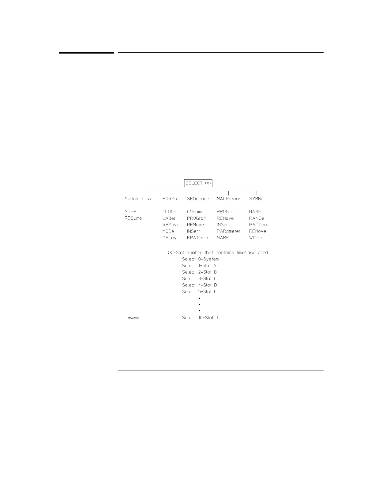
The command set for the Agilent 16522A is divided into four separate
subsystems. The subsystems are: FORMat, SEQuence, MACRo, and the
SYMBol subsystem. Each of the subsystems commands are covered in their
individual sections later in this chapter.
Each of these sections contain a description of the subsystem, syntax
diagrams and the commands in alphabetical order. The commands are
shown in long form and short form using upper and lower-case letters. For
example, FORMat indicates that the long form of the command is FORMAT
and the short form is FORM. Each of the commands contain a description of
the command and its arguments, the command syntax, and a programming
example.
The following figure shows the command tree for the pattern generator
module.
Pattern Generator Command Tree
3–8
Page 63

Programming the Agilent 16522A
Command Set Organization
Table 3-1 shows the alphabetical command to subsystem directory.
Table 3-1
Alphabetical Command to Subsystem Directory
Command Where Used
BASE SYMBol
CLOCk FORMat
COLumn SEQuence
DELay FORMat
EPATtern SEQuence
INSert MACRo, SEQuence
LABel FORMat
MODe FORMat
NAME MACRo
PARameter MACRo
PATTern SYMBol
PROGram SEQuence, MACRo
RANGe SYMBol
REMove FORMat, SEQuence, MACRo, SYMBol
RESume Module Level
STEP Module Level
WIDTh SYMBol
3–9
Page 64

Command Syntax:
Programming the Agilent 16522A
Module Status Reporting
Module Status Reporting
Each module reports its status to the Module Event Status Register
(MESR<N>) which in turn reports to the Combined Event Status Register
(CESR) in the Agilent 16500B/C mainframe (see
Programmer’s Guide
Module Event Status Enable Register (MESE<N>).
The following descriptions of the MESE<N> and MESR<N> commands
provide the module specific information needed to enable and interpret the
contents of the registers
MESE<N>
The MESE<N> command sets the Module Event Status Enable register bits.
The MESE register contains a mask value for the bits enabled in the MESR
register. A one in the MESE will enable the corresponding bit in the MESR
register; a zero will disable the bit.
The first parameter after the command specifies the module (<N> = 1...10
refers to the module in slot A...J). The second parameter specifies the enable
value.
The MESE query returns the current setting.
Refer to table 3-2 Module Event Status Register for bits, bit weights, and
what each bit masks in the module.
). The Module Event Status Register is enabled by the
:MESE<N><enable_mask>
Agilent 16500
<enable_mask>
Example
<N> {1|2|3|4|5|6|7|8|9|10}
integer 0 to 255
OUTPUT XXX;": MESE5 2"
This example enables bit one for slot E.
3–10
number of slot in which the module resides
Page 65

Programming the Agilent 16522A
Module Status Reporting
Query Syntax:
Returned Format:
Example
:MESE<N>?
[MESE] <enabl e_mask><NL>
10 OUTPUT XXX;":MESE2?"
20 ENTER XXX; Mes
30 PRINT Mes
40 END
This example reads status mask for slot B.
Table 3-2 Module Event Status Enable Register
Bit Weight Enables
7128 Not Used
664 Not Used
532 Not Used
416 Not Used
38 Not Used
24 Not Used
12 Not Used
01 Run Complete
The Module Event Status Enable Register contains a mask value for the bits
to be enabled in the Module Event Status Register (MESR). A one in the
MESE enables the corresponding bit in the MESR, a zero disables the bit.
MESR<N>
The MESR<N> query returns the contents of the Module Event Status
register.
Reading the register clears the Module Event Status Register.
3–11
Page 66

Programming the Agilent 16522A
Module Status Reporting
Table 3-3 shows each bit in the Module Event Status Register and its bit
weight for this module. When you read the MESR, the value returned is the
total bit weights of all bits that are high at the time the register is read.
The parameter 1...10 refers to the module in slot A...J respectively.
Query Syntax:
Returned Format:
:MESR<N>?
[MESR]<status><NL>
<N> {1|2|3|4|5|6|7|8|9|10}
<status>
Example
0 to 255
10 OUTPUT XXX;":MESR2?"
20 ENTER XXX; Mer
30 PRINT Mer
40 END
This example reads status register for slot B
Table 3-3 Module Event Status Register
Bit Weight Condition
7128Not Used
664Not Used
532Not Used
416Not Used
38Not Used
24Not Used
12Not Used
0 1 1 = Run complete
number of slot in which the module resides
0 = Run not complete
The MESR bit will be set at the end of the program or if a BREAK instruction is
encountered within the program.
3–12
Page 67
Module Level Commands
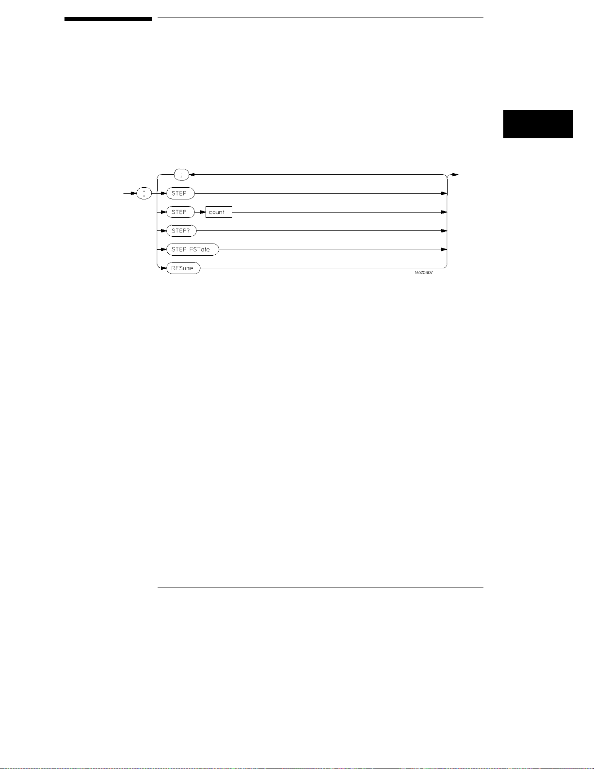
The Module Level Commands control the operation of pattern generator
programs. The two Module Level Commands are STEP and RESume.
Module Level Syntax Diagram
integer from 1 to 100,000 specifying the number of vectors stepped.
=
count
3–13
Page 68

Programming the Agilent 16522A
STEP
STEP
Command/Query
STEP command
Syntax
Example
STEP Count
command Syntax
<count>
The STEP command consists of four types: the STEP command, the STEP
Count command, the STEP query, and the STEP FSTate command.
The STEP command causes the pattern generator to step through the
number of vectors specified by the STEP Count command. If one of the
instructions is BREAK, STEP will not stop for it.
The STEP Count command specifies the vector range for the STEP
command. The valid vector range for the STEP Count command is from 1 to
100,000. The default is 1. If <count> is greater than the number of lines in
the program, STEP will loop back to the beginning until it has stepped
through <count> number of vectors.
The STEP query returns the current count.
The STEP FSTate (step first state) command outputs the first vector of the
sequence.
If the vectors have been changed since last run, they must be loaded into the
hardware with either the :START command or :STEP FSTate.
:STEP
OUTPUT XXX;": STEP"
STEP <c ount>
an integer from 1 to 100,000 specifying the number of vectors stepped.
Example
10 OUTPUT XXX;":STEP 20"
20 OUTPUT XXX;":STEP"
This example sets the step count to 20 in line 10, then in line 20 begins the
step command through the number of lines specified in line 10.
3–14
Page 69

Programming the Agilent 16522A
STEP
Query
Returned Format
Example
STEP FSTate
command Syntax
Example
:STEP?
[STEP] <count>
10 DIM Sc$[100]
20 OUTPUT XXX;":STEP?"
30 ENTER XXX;Sc $
40 PRINT Sc$
50 END
This example queries and prints the step count.
:STEP FS Tate
OUTPUT XXX;":STEP FSTATE"
3–15
Page 70

Programming the Agilent 16522A
RESume
RESume
Command
Command Syntax
Example
When the pattern generator encounters a BREAK instruction, program
execution is halted. The RESume command allows the program to continue
until another BREAK instruction is encountered, or until the end of the
program is reached.
:RESume
OUTPUT XXX;": RESUME"
3–16
Page 71
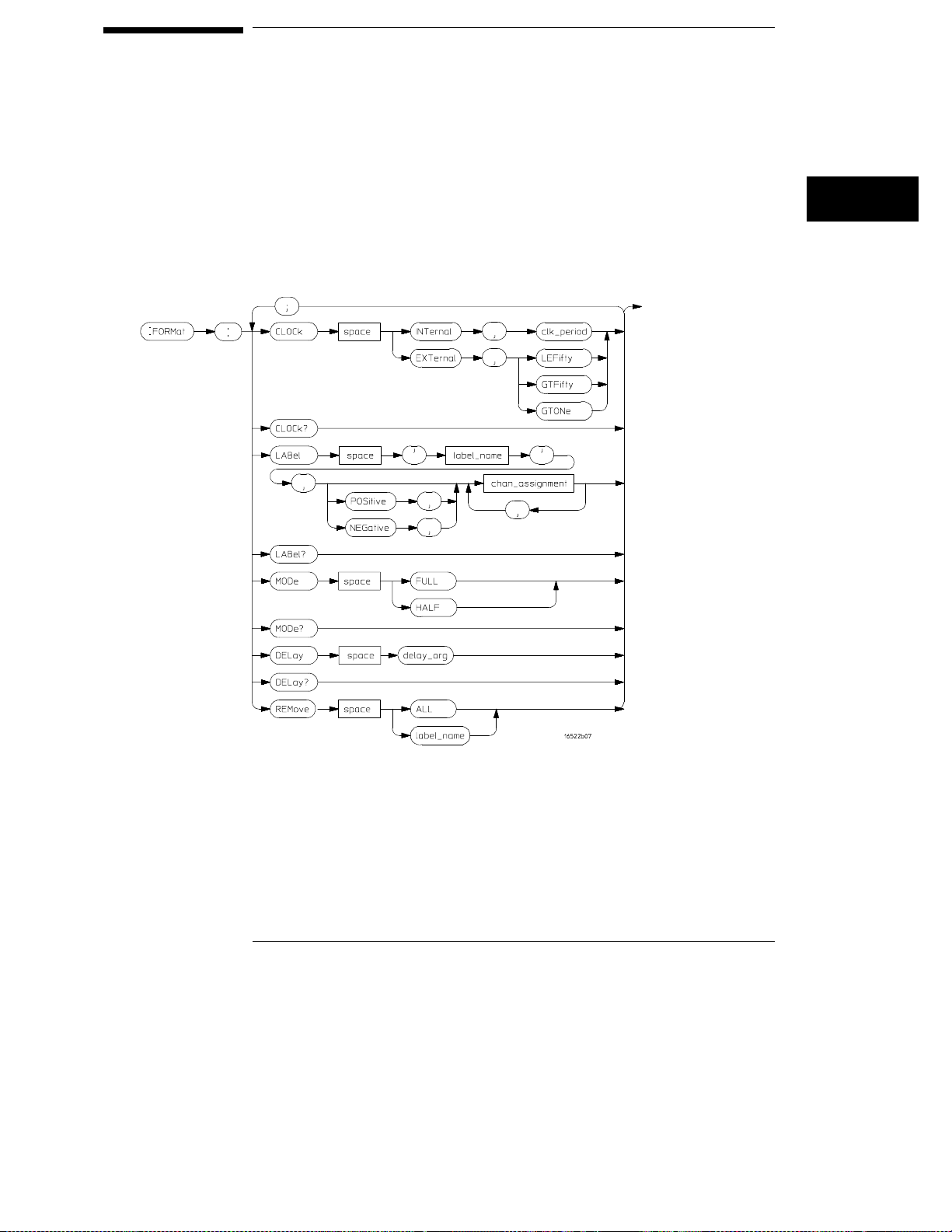
FORMat Subsystem
The commands of the Format subsystem control the pattern generator values
such as data output rate, delay, and the channels that you want to be active.
The Format subsystem also lets you specify the clock source and allows you
to group channels together under a common, user-defined name.
Format Subsystem Syntax Diagram
label name =
chan_assignment =
clk_period =
delay_arg =
a string of up to 6 alphanumeric characters
an integer from 0 to 255
a real number specifying the internal clock period
a integer specifying the delay
3–17
Page 72

Programming the Agilent 16522A
CLOCk
CLOCk
Command/Query
Command Syntax
<clk_period>
Query Syntax
Returned Format
The CLOCk command is used to specify the clock source for the pattern
generator. The choices are INTernal or EXTernal. With an internal clock
source, the clock period must also be specified (real number value).
With an external clock source, the clock frequency range must be specified
as one of the following:
Less than or equal to 50 MHz (LEFifty)
•
Greater than 50 MHz and less than or equal to 100 MHz (GTFifty)
•
Greater than 100 MHz (GTONe)
•
The maximum clock rate is limited by the output channel mode selected (see
FORMat:MODe command).
:FORMa t:CLOCk INTernal,<cl k_ period>
:FORMa t:CLOCk EXTernal,{LE Fi fty|GTFifty| GT ONe}
a real number clock period that corresponds to the front-panel selectable
clock period values.
:FORMat:CLOCk?
[:FORM at:CLOCk] INTernal,< cl k_period>
[:FORM at:CLOCk] EXTernal,{ LE Fifty|GTFift y| GTONe}
Example
10 DIM Cl$[100]
20 OUTPUT XXX;":FORMAT:CLOCK?"
30 ENTER XXX;Cl $
40 PRINT Cl$
50 END
This example queries and prints the current clock settings.
3–18
Page 73

DELay
Programming the Agilent 16522A
DELay
Command/Query
Command syntax
<delay_arg>
Query syntax
Returned format
The DELay command is used to specify the clock out delay. The clock out
delay setting allows positioning of the clock with respect to the data. The
delay setting that corresponds to zero is uncalibrated and must be measured
by the user to determine the basic clock/data timing. Subsequent settings
delay the clock approximately 1.3 ns per step.
The query returns the current clock out delay value.
:FORMat:DELay<delay_arg>
integer from 0 through 9
:FORMat:DELay?
[FORMat:DELay]<delay_arg>
3–19
Page 74

Programming the Agilent 16522A
LABel
LABel
Command/Query
The LABel command inserts a new label or modifies the contents of an
existing label. If more than 126 labels are specified, and an attempt is made
to insert another new label, the last label (bottom label) will be modified.
Only 16 labels may be inserted or modified at a time. If more than 16 labels
are specified per command, you will receive an error message.
Pattern generator channels can be assigned to only one label at a time. If
duplicate assignments are made, the last channel assignments take
precedence.
The second parameter sets the channel polarity. If the polarity is not
specified, the last polarity assignment is used. The last parameters assign the
active channels for each pod.
Each assignment parameter is a binary encoding of the channel assignments
of the pod. The pods are numbered in the same order as they appear in the
format menu, with zero representing the left-most pod (pod 5) of the
top-most card in the pattern generator module. A "1" in a bit position means
that the associated channel in that pod is included in the label. A "0" in a bit
position excludes the channel from the label. The minimum value for any pod
specification is 0, the maximum value for all pods is 255. A value of 255
includes all channels of a pod assignment. The query must specify a label
name and returns the current pod assignments and channel polarity for that
label. A maximum of 32 bits can be assigned to a label.
In half channel mode, only the four least significant bits of pod five are used.
Pods two and four are not used. Pods one and three use all eight bits. When
channel assignments are made in half channel mode, values are required for
three pods (1, 3, 5) per card.
Command Syntax
<label name>
<polarity>
:FORMat:LABel <label name>,[<polarity>,]<channel
assignment>, .... <channel assignment>
string of up to 6 alphanumeric characters
polarity of the channel outputs,NEGative or POSitive
3–20
Page 75

Programming the Agilent 16522A
LABel
<channel
assignment>
Example
Example
Query Syntax:
Returned Format:
Example
a string in one of the following forms:
’#B01...’
’#Q01234567..’
’#H0123456789ABCDEF...’
’0123456789...’
Full channel mode, all bits on pods 4 and 5:
OUTPUT XXX;":FORMAT:LABEL ’DATA’,POS,255,255,0,0,0"
Half channel mode, all bits on pods 3 and 5:
OUTPUT XXX;":FORMAT:LABEL ’STATUS’,NEG,15,255,0"
for binary
for octal
for hexadecimal
for decimal.
:FORMat:LABel? <label name>
[:FORMat:LABel] <label name>,<polarity>,<channel
assignment>, .... <channel assignment><NL>
10 DIM La$[100]
20 OUTPUT XXX;":FORMAT:LABEL? ’A’"
30 ENTER XXX;La $
40 PRINT La$
50 END
This example queries and prints the definition of label ’A’.
3–21
Page 76

Programming the Agilent 16522A
MODe
MODe
The MODe command is used to specify either FULL or HALF channel output
mode. Half channel mode allows a higher output data rate (greater than 100
MHz), but with only 20 channels per card.
Full channel output mode limits the maximum data rate to 100 MHz but
allows use of 40 channels per card.
The output mode selection sets the upper limit for the clock rate (see
FORMat:CLOCk command).
Command syntax:
Query syntax:
Returned format:
:FORMat:MODe{FULL|HALF}
:FORMat:MODe?
[FORMat:MODe]{FULL|HALF}
Assigning labels in half-channel mode erases previously-assigned labels.
3–22
Page 77

REMove
Programming the Agilent 16522A
REMove
Command
Command Syntax:
<label name>
Example
The REMove is used to delete a single label, or all labels from the format
menu. If a label name is specified, it must exactly match a label name
currently active in the format menu.
:FORMat:REMove {ALL|<label name>}
a string of up to 6 alphanumeric characters
OUTPUT XXX;": FORMAT:REMOVE ALL"
3–23
Page 78
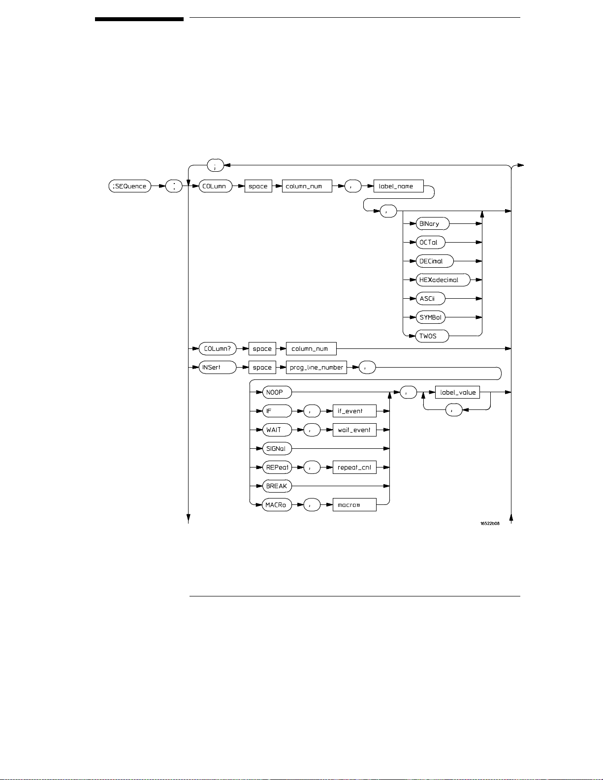
SEQuence Subsystem
The commands of the Sequence subsystem allow you to write a pattern
generator program using the parameters set in the Format subsystem.
SEQuence Subsystem Syntax Diagram
3–24
Page 79
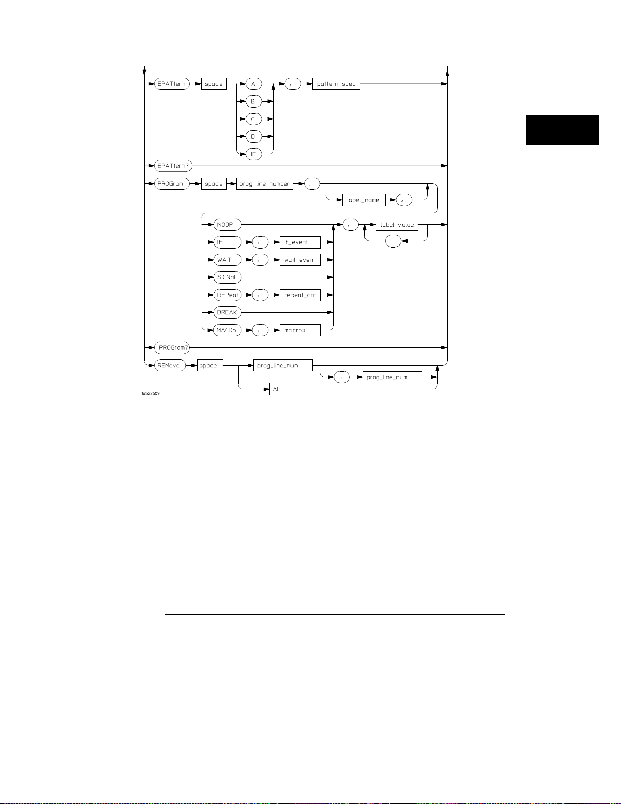
SEQuence Subsystem Syntax Diagram (cont.)
column_num =
label_name =
prog_line_num =
label_value =
’#B01...’ for binary
’#Q01234567...’ for octal
’#H0123456789ABCDEF...’ for hexadecimal
’0123456789...’ for decimal
repeat_cnt =
macro# =
if_event =
wait_event =
patter_spec =
an integer specifying the column that is to receive the
the label name that is to be removed
an integer specifying the program line number
a string in one of the following forms:
an integer from 1 through 20,000
an integer from 0 to 99
{IF | IMB}
{A | B | C | D | IMB}
an integer from 0 to 255
new
label
3–25
Page 80

Programming the Agilent 16522A
COLumn
COLumn
Command/Query
Command Syntax:
<column
number>
<label name>
Example
Query Syntax:
The COLumn command allows you to reorder the labels in the Sequence and
Macro menus and set the numerical base for each label. Label order in the
Format menu is not changed when the COLUMN command is used.
The first parameter of the command specifies the column number, followed
by a label name and an optional number base. If a number base is not
specified, the current number base for the label is used. The instruction field
(leftmost column on screen) cannot be moved.
The query must include a column number and returns the label in that
column and its base.
:SEQu ence:COLumn <column numb er>,’<label name>’
[,{BINary|OCTal|DECimal|HEXadecimal|ASCii|SYMBol
|TWOs}]
an integer specifying the column that is to receive the new label
a string of up to six alphanumeric characters specifying the label name that is
to be moved
OUTPUT XXX;": SEQ:COL 1,’A’,HEX"
:SEQue nce:COLumn? <column nu mb er>
Returned Format:
Example
[SEQuence:COLUMN] <column number>,<label name>,
{BINary|OCTal|DECimal|HEXadecimal|ASCII|
SYMBol|TWOS}
10 DIM Co$[100]
20 OUTPUT XXX;":SEQ:COL? 1"
30 ENTER XXX;Co $
40 PRINT Co$
50 END
3–26
Page 81

EPATtern
Programming the Agilent 16522A
EPATtern
Command/Query
The EPATtern command is used to specify the event patterns used by the
WAIT and IF commands. The pattern generator has three external input
qualifiers (WAIT2, WAIT1, and WAIT0). There are eight combinations of the
three input qualifiers that may be OR’ed together to create an event pattern
specification. Mapping of these input qualifier patterns to an event pattern
specification is shown below.
WAIT2 WAIT1 WAIT0
000
001
010
011
100
101
110
111
The query returns the current pattern specification for the given event.
Command syntax:
:SEQuence:EPATtern { A|B|C|D|IF },<pattern_spec>
MSB
xxxxxxxx
<pattern_spec>
LSB
<pattern_spec>
Query syntax:
Return format:
an integer between 0 and 255 mapping input qualifier combinations as shown
above.
:SEQuence:EPATtern? { A|B|C|D|IF }
[:SEQuence:EPATtern] { A|B|C|D|IF },<pattern_spec>
See next page for an example.
3–27
Page 82

Programming the Agilent 16522A
EPATtern
Example
To specify an event pattern of (0, 1, 0) [Wait2=0, Wait1=1, Wait0=0] use a
<pattern_spec> of 4 (0000 0100).
To specify an event pattern of (0, 0, 0) use a <pattern_spec>
of 1 (0000 0001).
To specify an event pattern of (0, 1, 1) OR (1, 1, 0) OR ( 1, 1, 1) use a
<pattern_spec> of 200 (1100 1000).
3–28
Page 83

INSert
Programming the Agilent 16522A
INSert
Command
The INSert command is the basic command used to build a pattern generator
sequence. This command is used to insert (or add) a sequence statement
after the specified line number.
The first parameter is the line number. The instruction is inserted in the
sequence after the specified line number. Sequence lines with instructions
other than NOOP cannot be inserted:
Immediately after the INIT SEQUENCE START line.
•
Immediately before or after the start of an IF.
•
Immediately before or after the end of an IF.
•
Immediately after the MAIN SEQUENCE START line.
•
After the MAIN SEQUENCE END line.
•
Immediately before the MAIN SEQUENCE END line.
•
No sequence lines may be inserted between the INIT SEQUENCE END and
the MAIN SEQUENCE START lines.
If the line number specified is greater than the MAIN SEQUENCE END line
number, the line will be inserted at the last legal location in the main
sequence. A legal pattern generator sequence is required to have at least two
lines in the main sequence (between MAIN SEQUENCE START and MAIN
SEQUENCE END lines).
The second parameter is the instruction for this sequence line. The available
instructions are described below
The third parameter is an optional instruction argument. This parameter will
only appear when required by a specific instruction.
The last parameter(s) are the data assignments for this line. These
assignments are normally made one per label, starting with the left-most
column in the display. Note the exception described for the MACRo
instruction.
You cannot assign values to more than 16 labels per instruction.
3–29
Page 84

Programming the Agilent 16522A
INSert
Instructions
NOOP
The NOOP instruction means there is no instruction for this line.
BREak
stop at this line. Use the RESume command to advance to the next
sequence line.
SIGNal
instruction. When the pattern generator encounters a SIGNal
instruction, it will output a signal to the internal Intermodule Bus (IMB).
This signal is used to trigger the other modules in the Agilent 16500B/C
frame that are linked with the IMB.
WAIT
wait for the occurrence of the specified event pattern(s). The event
patterns are specified elsewhere (SEQuence: EPATtern command). The
event to be waited for by this particular command is specified by the
optional instruction argument parameter. Once the specified event
occurs, the pattern generator program proceeds to the next state.
Valid wait events are { A | B | C | D | IMB }
IF
specified condition is true. The IF event pattern can be specified
elsewhere (SEQuence:EPATtern command).
The condition to be tested by the IF instruction is specified by the optional
instruction argument parameter. If the specified condition is true, the
sequence states included in the IF (lines between IF and IF END) are
executed. If the condition is not true, the sequence states within the IF are
skipped. Valid IF events are {IF | IMB}.
Note that there are clock speed, channel count, and location restrictions on
the use of the IF instruction.
The BREak instruction causes the execution of the sequence to
The SIGNal instruction is the complement of the WAIT IMB
The Wait instruction causes the pattern generator to stop and
The IF instruction allows a sequence of program states to occur if a
REPeat
executed repetitively some number of times. The repeat count is
specified in the optional instruction argument parameter.
Inserting a REPeat instruction causes three sequence lines to be generated.
The REPeat instruction line, a data line within the body of the repeat, and an
END LOOP instruction line.
No data appears in the REPEAT and END LOOP lines. The data specified as
part of the remote control command string appears in the body of the repeat
loop. Additional data lines can be added to the body of the repeat loop by
3–30
The REPeat instruction allows a group of sequence states to be
Page 85

Programming the Agilent 16522A
INSert
inserting lines as needed. The repeat loop is assigned a loop number by the
system and is used to connect the limits of the repeat loop.
Note that there are location restrictions on the use of the REPeat instruction.
Command Syntax
<line_number>
<event>
<count>
<data_value>
<#>
MACRo#
The MACRo# instruction is used to invoke a previously
defined user macro. The macro number is part of the instruction string
(not the optional instruction argument parameter). If the macro has
been defined to use passed-in parameters, those parameter values are
passed in via the data value fields. If no parameters are defined, a single
dummy parameter must be used (’0’). There is otherwise no data
associated with a macro instruction.
:SEQu ence:INSert <line_numb er>,{NOOP|IF,<event>|
WAIT,<event>|SIGNal|REPeat,<count>|BREAK|
MACRo<#>},<data_value>,<data_value>,...
integer where instruction/data will be inserted after
{ A | B | C | D | IF | IMB }
integer repeat count
macro number
a string in one of the following forms:
’#B01...’
’#Q01234567...’
’#H0123456789ABCDEF...’
’0123456789...’
for binary
for octal
for hexadecimal
for decimal
Example
10 OUTPUT XXX; " :SEQ: INS 248, NOOP, ’17’, ’34’, ’121’"
20 OUTPUT XXX; " :SEQ: INS 1786, WAIT, A,’17’, ’34’, ’121’"
30 OUTPUT XXX; " :SEQ: INS 2652, REPEAT, 26, ’17’, ’34’, ’121’"
40 OUTPUT XXX; " :SEQ: INS 3166, MACR4, ’#HABCD’"
41 !Passes a single parameter to this instance of MACRO #4.
50 OUTPUT XXX; " :SEQ: INS 3186, MACR6, ’0’"
51 !Assume no parameter defined for MACRO 6.
3–31
Page 86

Programming the Agilent 16522A
PROGram
PROGram
Command/Query
The PROGram command is used to modify an existing pattern generator
sequence line.
The first parameter is the line number. The instruction to be modified is at
the specified line number. Note that some lines cannot be modified
(SEQUENCE START and END) and some instructions can have parameters
modified, but the instruction type cannot be changed (REPeat can have the
repeat count changed, but it cannot be changed to a NOOP).
The second parameter is an optional label name. The label name allows any
data values specified in the command to be assigned starting with the label
name rather than defaulting to the first label. This is useful when modifying
only a portion of the data for a sequence line.
You cannot specify more than 16 labels per PROGram command. Use the
optional label parameter if the line you want to modify has more than 16 labels.
The third parameter is the instruction. The options for this parameter are
described below.
The fourth parameter is an optional instruction argument. This parameter
will only appear when required by a specific instruction as described below.
The last parameter(s) are the data assignments for this line. These
assignments are normally made one per label, starting with the left-most
column in the display.
Note that some instructions cannot be modified. To change the instruction
type in these cases, it is necessary to first REMove the line(s) and INSert
new lines(s).
The query returns the current contents (instruction and data) for the
specified line number.
Instructions
NOOP
BREak
stop at this line. Use the RESume command to advance to the next line
sequence.
3–32
The NOOP instruction means there is no instruction for this line.
The BREak instruction causes the execution of the sequence to
Page 87

Programming the Agilent 16522A
PROGram
SIGNal
Intermodule Bus (IMB). This signal is used to trigger the other modules
in the Agilent 16500B/C frame that are linked with the IMB.
WAIT
wait for the occurrence of the specified event pattern(s). The event
patterns are set by the SEQuence: EPATtern command. The event to be
waited for by this particular command is specified by the optional
instruction argument parameter. Once the specified event occurs, the
pattern generator program proceeds to the next state.
IF
specified condition is true. The IF event pattern is specified by the
SEQuence:EPATtern command.
The IF and END IF sequence lines cannot be modified other than changing
the if condition.
The condition to be tested by the IF instruction is specified by the optional
instruction argument parameter. If the specified condition is true, the
sequence states include the IF (lines between IF and IF END) are executed.
If the condition is not true, the sequence states within the IF are skipped.
Valid IF events are {IF | IMB}.
REPeat
executed repetitively some number of times. The repeat count is
specified in the optional instruction argument parameter.
The SIGNal instruction outputs a signal to the internal
The WAIT instruction causes the pattern generator to stop and
The IF instruction allows a sequence of program states to occur if a
The REPeat instruction allows a group of sequence states to be
Command Syntax
The REPeat and END LOOP sequence lines cannot be modified other than by
changing the loop count.
MACRo#
macro. It
is part of the instruction string (not the optional instruction argument
parameter). If the macro has been defined to use passed-in parameters,
they are passed in via the data value fields. If there are on parameters
associated with the macro, a single dummy parameter must be used (’0’).
There is otherwise no data associated with a macro instruction.
The MACRo# instruction invokes a previously defined user
inserts
the macro, rather than modifying it. The macro number
:SEQue nce:PROGram <line_nu mb er>,
[<optional_label>,]{ NOOP | IF,<event> |
WAIT,<event> | SIGNal | REPeat,<count> | BREAK |
MACRo <#> },<data_value>,<da ta_value>,...
3–33
Page 88

Programming the Agilent 16522A
PROGram
<line_number>
<optional_
label>
<event> {A|B|C|D|IF|IMB}
<count>
<data_value>
Query Syntax:
Returned Format:
<#>
integer where instruction/data will be modified
a string of up to 6 alphanumeric characters specifying the label where
modification begins.
integer repeat count
macro number
a string in one of the following forms:
’#B01...’
’#Q01234567...’
’#H0123456789ABCDEF...’
’0123456789...’
for binary
for octal
for hexadecimal
for decimal
:SEQuence:PROGram? <line_number>
Note that the returned format of a SEQ:PROG? query is the same instruction
text that appears in a front panel listing on the Agilent 16500B/C. This text
string cannot be used as part of a command sent to the Agilent 16522A.
{IF (External Pattern = #) | END IF | WAIT
<event> | SIG IMB | START LOOP # REPEAT # TIMES |
END LOOP # | BREAK | MACRO Macro# () | INIT
SEQUENCE START | INIT SEQUENCE END | MAIN
SEQUENCE START | MAIN SEQUENCE END},<data_value>,
<data_ value>, ...
Example
10 OUTPUT XXX; " :SEQ: PROG 248, NOOP, ’17’, ’34’, ’121’"
20 OUTPUT XXX; " :SEQ: PROG 1786, WAIT, A,’17’, ’34’, ’121’"
30 OUTPUT XXX; " :SEQ: PROG 2652, REPEAT, 26, ’17’, ’34’, ’121’"
40 OUTPUT XXX; " :SEQ: PROG 3166, MACR4, ’#HABCD’"
41 ! Passes a single parameter to this instance of MACRO #4.
50 OUTPUT XXX; " :SEQ: PROG 3186, MACR6, ’0’"
51 ! Assume no parameter defined for MACRO 6.
3–34
Page 89

REMove
Programming the Agilent 16522A
REMove
Command
Command Syntax:
<program line
number>
<program line
range>
Example
The REMove command allows you to remove one or several lines from the
pattern generator program. If only one parameter number is given, that line
number is deleted. If two numbers are given, the range of lines between those
two values inclusive is deleted. The command REMove ALL deletes the entire
program.
SEQuence:REMove{ <program line number[,<program
line ra nge>]|ALL>}
an integer specifying the program line to be removed
an integer specifying the last line number in a range of lines to remove.
OUTPUT XXX;": SEQ:REM 1,4"
3–35
Page 90

MACRo Subsystem
The commands of the MACRo subsystem allow you to write and edit macros
for use in the pattern generator program. Up to 100 macros may be called
into the main listing program. The macros are labeled Macro0 through
Macro99.
Macro0 is always available (initial contents are START/END lines only). All
other macros are created whenever a MACRo<#> subheader that is not yet
defined is used. The new macro will then appear on all macro lists until a
MACRo<#>:REMove command is issued.
A macro can be named (MACRo<#>:NAME command) but cannot be
referenced by remote control commands using that name.
The SEQuence:COLumn command is used to define the ordering of the
sequence display listing. Macro display listings will appear in the same order
as the main sequence. Changing the display while on a macro listing will also
affect the main sequence when you return to that display listing.
The SEQuence:EPATtern command is used to define event patterns that are
shared by both the main sequence and all macros. Changing an event pattern
definition for use by a single macro will change its definition for all other
macros and the main sequence.
The command REMove ALL can be used to totally clear the contents of a
macro, but it does not remove the macro from the macro list. The macro is
still accessible from the sequence, but the macro consist of only two lines.
The command REMove MACRo can be used to totally remove all contents of
a macro as well as any external reference to that macro. Note that while
Macro0 can be totally cleared, it cannot be removed from the macro list.
3–36
Page 91
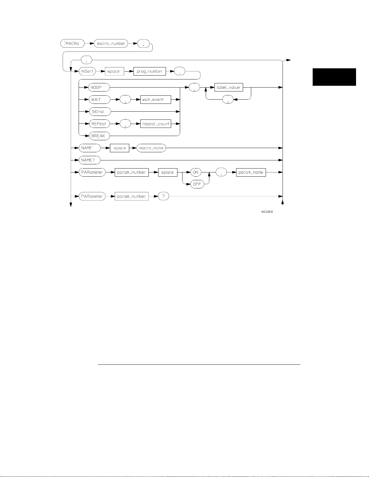
MACRo Subsystem Syntax Diagram
3–37
Page 92
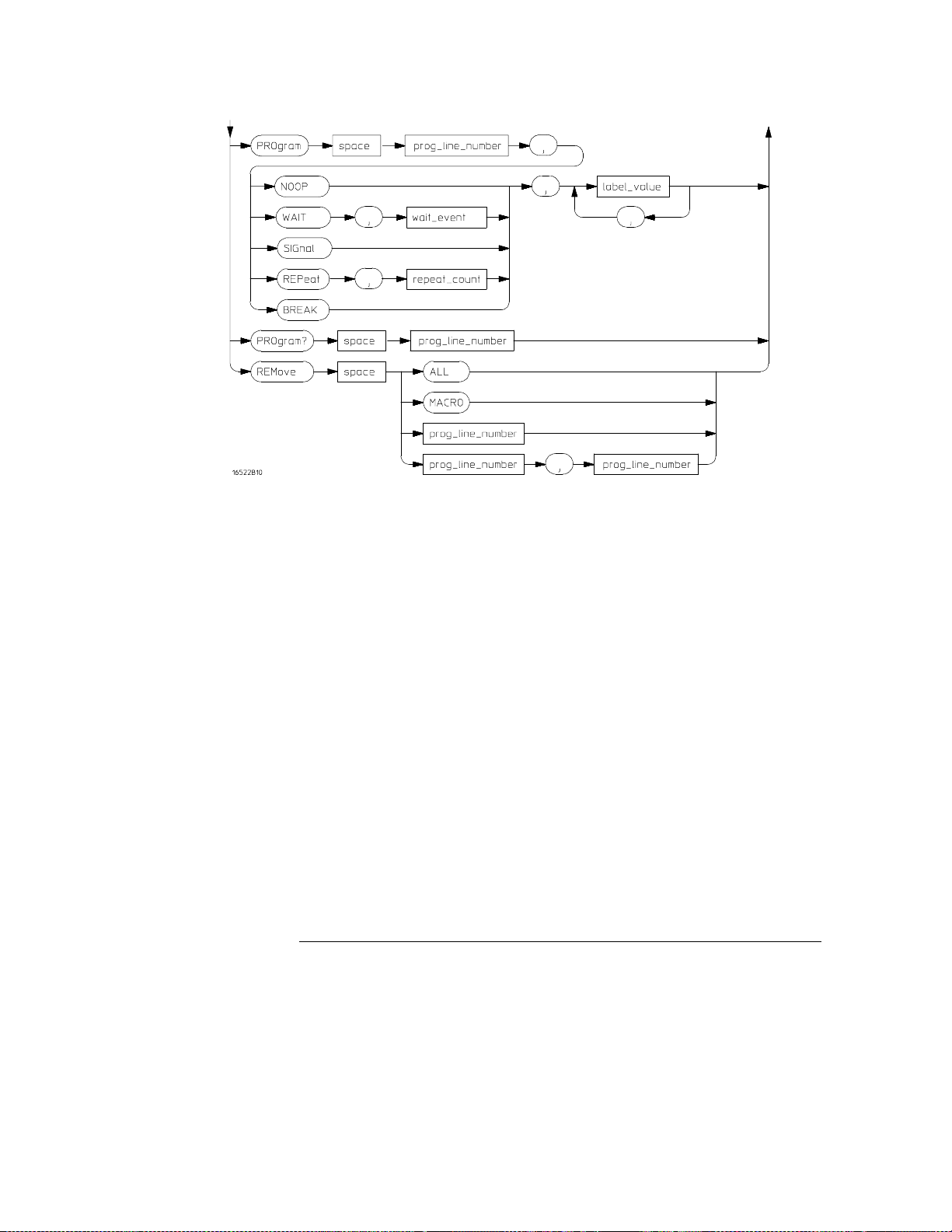
MACRo Subsystem Syntax Diagram (cont.)
prog_line_num =
macro_name =
macro_number =
param_name =
param_number =
repeat_count =
wait_event =
label_name =
label_value =
an integer specifying the program line number
character string up to 6 characters in length
an integer 0 through 99 specifying macro to act on
character string up to 6 characters in length
an integer 0 through 9
an integer from 1 through 20000
{ A | B | C | D | IMB }
character string up to 6 characters in length
data entry in one of the following forms:
’#B01...’ for binary
’#Q01234567...’ for octal
’#H012345679ABCDEF...’ for hexadecimal
’0123456789...’ for decimal
PARameter<#> for passed in macro parameter (# = 0 through 9)
3–38
Page 93

INSert
Programming the Agilent 16522A
INSert
Command
The INSert command is the basic command used to build a pattern generator
macro. This command is used to insert (or add) a macro statement after the
specified line number.
The first parameter is the line number. The instruction and/or data will be
inserted in the macro after the specified line number. You cannot insert a
line just before the last data row. Macro lines cannot be inserted after the
MACRO END line.
If the line number specified is greater than the MACRO END line number, the
line will be inserted at the last legal location in the macro.
The second parameter is the instruction for this macro line. The available
instructions are described below
The third parameter is an optional instruction argument. This parameter will
only appear when required by a specific instruction.
The last parameter(s) are the data assignments for this line. These
assignments are normally made one per label, starting with the left-most
column in the display. In addition to the normal data values, parameters
passed in with a macro call can be inserted within the body of the macro.
Instructions
NOOP
BREak
stop at this line. Use the RESume command to advance to the next
macro line.
The NOOP instruction means there is no operation for this line.
The BREak instruction causes the execution of the sequence to
3–39
Page 94

Programming the Agilent 16522A
INSert
SIGNal
Intermodule Bus (IMB). This signal is used to trigger the other modules
in the Agilent 16500B/C frame that are linked with the IMB.
WAIT
wait for the occurrence of the specified event pattern(s). The event to
be waited for by this particular command is specified by the optional
instruction argument parameter. Once the specified event occurs, the
pattern generator program proceeds to the next state.
Valid wait events are { A | B | C | D | IMB }. Their patterns are set using the
SEQuence: EPATtern command.
REPeat
repetitively some number of times. The repeat count is specified in the
optional instruction argument parameter.
Inserting a REPeat instruction causes three lines to be generated: the
REPeat instruction line, a data line within the body of the repeat, and an
END LOOP instruction line. No data appears in the REPEAT and END LOOP
lines. The data specified as part of the remote control command string
appears in the body of the repeat loop. Additional data lines can be added to
the body of the repeat loop by inserting lines as needed. The repeat loop is
assigned a loop number by the system and is used to connect the limits of the
repeat loop.
The SIGNal instruction outputs a signal to the internal
The WAIT instruction causes the pattern generator to stop and
The REPeat instruction allows a group of states to be executed
3–40
Page 95

Programming the Agilent 16522A
INSert
Command Syntax
<line_number>
<event> { A | B | C | D | IMB }
<count>
<m#>
<p#>
<data_value>
Example
:MACRo<m#>:INSert <line_number>, { NOOP |
WAIT,<event> | SIGNal | REPeat,<count> | BREAK }
,<data_value>,<data_value>,...
integer which line instruction/data will be inserted after
integer repeat count
macro number (integer 0 through 99)
parameter number (integer 0 through 9)
a string in one of the following forms:
’#B01...’
’#Q01234567...’
’#H0123456789ABCDEF...
’0123456789...’
PARameter<p#>
OUTPUT XXX;":MACRO4:INSERT 3, BREAK, PAR1, ’13’"
for binary
for octal
’ for hexadecimal
for decimal
3–41
Page 96

Programming the Agilent 16522A
NAME
NAME
Command/Query
Command syntax:
<macro_name>
Query syntax:
Return format:
<#>
The NAME command is used to specify a name for a macro. This name will
then appear in the front panel lists and displays in place of the more generic
"Macro #" string.
The name cannot be used to reference the macro in programs. It is intended
for use as a means to clarify or document sequence listings and displays.
The query returns the user-defined macro name.
:MACRo<#>:NAME <macro_name>
a string up to six alphanumeric characters in length
macro number (integer 0 through 99).
:MACRo<#>:NAME?
[:MACRo<#>:NAME] <macro_name>
3–42
Page 97

PARameter
Programming the Agilent 16522A
PARameter
Command/Query
Command syntax:
<m#>
<p#>
<name>
Query syntax:
Returned format:
The PARameter command is used to enable and name parameters for a
macro. The parameter name is optional, and if used, is for use on displays
and listings only. When a parameter is enabled, macro calls from the
sequence can pass values to the macro. These values can then be used as
data values in the body of the macro.
The query returns the current status of a parameter and its name.
:MACRo<m#>:PARameter<p#> { ON | OFF }[,<name>]
macro number (integer 0 through 99)
parameter number (integer 0 through 9)
string up to six alphanumeric characters in length
:MACRo<m#>:PARameter<p#>?
[:MACRo<m#>:PARameter<P#>] { ON | OFF },<name>
3–43
Page 98

Programming the Agilent 16522A
PROGram
PROGram
Command/Query
The PROGram command is used to modify an existing pattern generator
macro line.
The first parameter is the line number of the instruction to be modified. Note
that some lines cannot be modified (MACRO and MACRO END) and some
instructions can have parameters modified. The instruction type cannot be
changed (REPeat can have the repeat count changed, but it cannot be
changed to a NOOP).
The second parameter is an optional label name. The label name allows any
data values specified in the command to be assigned starting with the label
name rather than defaulting to the first label. This is useful when modifying
only a portion of the data for a macro line.
You can only modify 16 labels per PROGram command. To modify more than 16
labels, use the optional label name parameter.
The third parameter is the instruction. The options for this parameter are
described below.
The fourth parameter is an optional instruction argument. This parameter
will only appear when required by a specific instruction as described below.
The last parameter(s) are the data assignments for this line. These
assignments are normally made one per label, starting with the left-most
column in the display. In addition to the normal data values, parameters
passed in with a macro call can be inserted within the body of the macro.
Specifying more than 16 data assignments will cause a command error.
Note that some instructions cannot be modified. To change the instruction
type in these cases, it is necessary to first REMove the line(s) and INSert
new lines(s).
The query returns the current contents (instruction and data) for the
specified line number.
3–44
Page 99

Instructions
NOOP
The NOOP instruction means there is no operation for this line.
Programming the Agilent 16522A
PROGram
BREak
stop at this line. Use the RESume command to advance to the next line
macro.
SIGNal
Intermodule Bus (IMB). This signal is used to trigger the other modules
in the Agilent 16500B/C frame that are linked with the IMB.
WAIT
wait for the occurrence of the specified event pattern(s). The event to
be waited for by this particular command is specified by the optional
instruction argument parameter. Once the specified event occurs, the
pattern generator program proceeds to the next state.
Valid WAIT events are { A | B | C | D | IMB }. Their patterns are set using the
SEQuence: EPATtern command.
REPeat
executed repetitively some number of times. The repeat count is
specified in the optional instruction argument parameter.
The REPeat and END LOOP sequence lines cannot be modified other than to
change the loop count.
The BREak instruction causes the execution of the macro to
The SIGNal instruction outputs a signal to the internal
The WAIT instruction causes the pattern generator to stop and
The REPeat instruction allows a group of macro states to be
3–45
Page 100

Programming the Agilent 16522A
PROGram
Command Syntax
<line_number>
<optional_
label>
<event> { A | B | C | D | IMB}
<count>
<m#>
<p#>
<data_value>
:MACRo<m#>:PROGram <line_number>,
[<optional_label>,]{ NOOP | WAIT,<event> | SIGNal
| REPeat,<count> | BREAK }
,<data_value>,<data_value>,...
integer specifying the line of instruction/data to be modified
a string of up to six characters specifying a label
integer repeat count
macro number (integer 0 through 99)
parameter number (integer 0 through 9)
a string in one of the following forms:
’#B01...’
’#Q01234567...’
’#H0123456789ABCDEF...’
’0123456789...’
PARameter<p#>
for binary
for octal
for hexadecimal
for decimal
Query Syntax:
Returned Format:
:MACRo<#>:PROGram? <line_number>
[:MACRo<#>:PROGram] <line_number>, { NOOP | WAIT
<event> | SIG IMB | BREAK | MACRO END | START
LOOP # REPEAT # TIMES | END LOOP # | MACRO
Macro# () },<data_value>, <data_value>, ...
3–46
 Loading...