

Page 1

User’s Reference
Publication number 16517-97006
January 1999
For Safety information, Warranties, and Regulatory
information, see the pages behind the Index
Copyright Hewlett-Packard Company 1987, 1990, 1993, 1996, 1997, 1999
All Rights Reserved
HP 16517A/18A
4-GSa/s Timing and
1-GSa/s Synchronous State
Logic Analyzer
Page 2

The HP 16517A 4-GSa/S Timing and 1-GSa/S State Logic Analyzer
ii
Page 3

In This Book
The User’s Reference contains field and
feature definitions. Use this part of the
manual set for information on what the
menu fields do, what they are used for,
and how the features work.
The User’s Reference is divided into
chapters covering general product
information and probing. In addition,
there are separate chapters for each
analyzer menu, a chapter for markers, a
chapter for error messages, and a chapter
for instrument specifications.
You have the choice of using the analyzer
as either a synchronous state analyzer or
a timing analyzer. Some menus in the
analyzer will change depending on the
acquisition mode used. For example,
because a timing analyzer does not use
external clocks, the external clock
assignment fields in the Format menu will
not be available.
If a menu field is only available to a
particular acquisition mode, the field is
designated (Timing only) or (State only)
after the field name. If no designation is
shown, the field is available for both state
and timing.
1
General Information
2
Probing
3
The Format Menu
4
The Trigger Menu
5
The Listing Menu
6
The Waveform Menu
7
The Compare Menu
8
The Chart Menu
Markers and
9
Stop Measurement
10
Skew Adjust
11
Error Messages
Specifications and
12
Characteristics
13
Installation and Service
Index
iii
Page 4

iv
Page 5

Contents
1 General Information
User Interface 1–4
Configuration Capabilities 1–5
Accessories Supplied 1–6
Accessories Available 1–6
2 Probing
Probing 2–2
Probing System Description 2–4
Probing Accessories 2–6
Probing Considerations 2–9
Orientation Between Probe Tip and Interface 2–10
3The Format Menu
Synchronous State Acquisition Mode 3–3
Conventional Timing Acquisition Mode 3–4
Select Clock Field (State Only) 3–5
Set Sample Offset Field (State Only) 3–6
Pod Threshold Field 3–8
Label Polarity Fields 3–9
Bit Assignment Fields 3–10
Activity Indicators 3–12
Symbols Field 3–12
4The Trigger Menu
Trigger Sequence Levels 4–4
Modify Trigger Field 4–6
Contents–1
Page 6

Contents
Pre-defined Trigger Macros 4–9
Using Macros to Create a Trigger Specification 4–11
Timing Trigger Macro Library 4–12
State Trigger Macro Library 4–15
Creating a User Level 4–17
Resource Terms 4–25
Assigning Resource Term Names and Values 4–27
Label and Base fields 4–31
Acquisition Control 4–32
Trigger Position Field 4–33
Sample Period Field (Timing only) 4–34
Samples/Clock Field(State only) 4–34
Armed By Field 4–37
5The Listing Menu
Markers Field 5–3
Data Roll Field 5–3
Label and Base Fields 5–4
Show States All/Ext Clock (State only) 5–5
Sample Offset Field (State only) 5–6
Specify Patterns Field 5–6
Acquisition Control Field 5–6
6The Waveform Menu
Acquisition Control Field 6–3
Accumulate Field 6–4
Seconds Per Division Field 6–5
Delay Field 6–6
Sample Period Display (Timing only) External Clock Period Display (State
only) 6–7
Markers Field 6–8
Contents–2
Page 7

Waveform Display 6–9
Display Location Reference Line 6–10
External-Clock Indicators (State only) 6–11
Blue Bar Field 6–12
Channel Mode Field 6–14
Module and Label Fields 6–16
Action Insert/Replace Field 6–17
Delete and Delete All Fields 6–18
Waveform Size Field 6–19
Sample Offset Field (State only) 6–20
Reset Statistics Field 6–20
7The Compare Menu
Reference Listing Field 7–4
Difference Listing Field 7–5
Copy Listing to Reference Field 7–7
Find Error Field 7–8
Compare Full / Compare Partial Field 7–9
Mask Field 7–10
Specify Stop Measurement Field 7–11
Data Roll Field 7–14
Bit Editing Field 7–15
Label and Base Fields 7–16
Contents
8The Chart Menu
The Y Markers 8–4
Markers Field 8–5
Rescale 8–6
Axis Control Field 8–8
Accumulate Field 8–11
Contents–3
Page 8

Contents
9 Markers and Stop Measurements
Markers Field 9–3
Pattern Markers 9–4
Find X-pattern / O-pattern Field (Listing and Chart) 9–5
Occurrence Counter Field (Listing and Chart) 9–5
From Trigger / Start / X Marker Field 9–6
X-pat / O-pat Occurrence Fields (Waveform menu) 9–7
Center Screen Field (Waveform and Chart) 9–7
X to O Display Field (Waveform and Chart) 9–7
Specify Patterns Field 9–8
Stop Measurement Field 9–10
Clear Pattern Field 9–11
Time Markers 9–12
Trig to X / Trig to O Fields 9–13
Marker Label / Base and Display (Waveform menu) 9–13
Statistics Markers 9–14
Reset Statistics Field (Waveform menu) 9–15
Clear Statistics Field (Chart menu) 9–15
10 Skew Adjust
To Calibrate the Data Acquisition Module 10–2
To Adjust the Channel-to-Channel Skew 10–3
Connect the Logic Analyzer 10–3
Set Up the Logic Analyzer 10–4
To Save or Discard the Skew Factors 10–6
Contents–4
Page 9

11 Error Messages
Error Messages 11–3
Warning Messages 11–4
Advisory Messages 11–7
Skew Adjust and Performance Verification Messages 11–8
12 Specifications and Characteristics
Specifications 12–3
Characteristics 12–4
13 Installation and Service
To Inspect the Module 13–3
To Prepare the Mainframe 13–3
To Configure a One-card Module 13–5
To Configure a Multi-card Module 13–5
To Install the Module 13–7
To Test the Module 13–8
Contents
To Perform the Self-tests 13–9
Access the Self-tests 13–9
Perform the Functional Tests 13–10
Perform the Skew Adjustments and Tests 13–11
Exit the Self-tests 13–12
To Return Assemblies 13–13
To Clean the Logic Analyzer Module 13–13
Index
Contents–5
Page 10

Contents–6
Page 11

1
General Information
Page 12

Logic Analyzer Description
The HP 16517A/18A Synchronous Timing Analyzer module is part of a
family of general-purpose logic analyzers. The HP 16517A/18A is a
multi-card module that is used with the HP 16500 mainframes and the
HP 16501A Expansion Frame.
The HP 16500 mainframe is designed for use by digital and
microprocessor hardware and software designers. The HP 16500
mainframe has HP-IB, RS-232-C, and Ethernet LAN interfaces for
hard copy printouts, postprocessing of measurement data, and control
by a host computer.
The HP 16517A/18A analyzer can be configured in the following ways:
• The HP 16517A master can run as a single-card module or have up
to four HP 16518A expansion cards added for a multi-card module.
• Channel width varies from 16 channels on the HP 16517A master,
up to 80 channels when four HP 16518A expansion cards are added.
• Channel memory depth is 64 Kbytes in both full-channel state and
timing modes or 128 Kbytes in half-channel timing mode.
Timing Modes
The HP 16517A/18A has two timing modes. In full-channel timing
mode, data is sampled at up to 2 GHz. In half-channel timing mode,
data is sampled at 4 GHz.
Synchronous State Mode
In the full-channel state mode, a synchronous external clock running
at speeds up to 1 GHz can be used as the sample clock. In addition,
the sample point can be offset to ensure a sample where you know
data is valid.
1–2
Page 13

General Information
Not only can you sample at the external clock transitions, but you can
set the analyzer to oversample, in powers of two, up to 32x, or, up to a
maximum of 2 GHz sample rate. Each point of oversampling is
precisely distributed evenly within the external clock period.
Triggering
Defining a trigger specification is as easy as picking a predefined
macro from a trigger macro library. Trigger macros can be used by
themselves or in combination with each other. Resource terms
include four global patterns, two global edges, and one level
dependent timer/counter. By using trigger macros, or defining your
own trigger specification, the user-friendly and flexible triggering
architecture lets you create a large array of trigger sequencing or
qualification needed.
Acquisition Control
Data storage can begin at either the start, center, end, or a
user-defined point within memory. In addition, if the data of interest
occurs a relatively long time after trigger, you can delay storage after a
trigger by a user-defined amount. With all the acquisition control
available, you can fill acquisition memory very efficiently.
Measurement Display
Measurement data is displayed as waveforms or state data listings.
State data can be compared bit by bit to a user-defined reference
image. In the state listing, you can choose to display either sample
clock transitions or both sample clock and oversampling clock
transitions. In the timing waveform display, you can show state values
integrated in the waveform.
1–3
Page 14

General Information
User Interface
User Interface
The HP 16500 Logic Analysis System has four easy-to-use user interface
devices: the knob, the touchscreen, the optional mouse (standard in the
HP 16500C), and the optional keyboard.
The knob on the front panel is used to move the cursor on certain menus, to
increment or decrement numeric fields, and to roll the display.
The touchscreen fields can be selected by touch or with the optional mouse.
To activate a touchscreen field by touch, simply touch the screen over any
dark blue box on the display with your finger until the field changes color.
Then remove your finger from the screen to activate your selection. The area
under your finger when you remove it from the screen is the area selected.
To activate a field with the mouse, position the cursor (+) of the mouse over
the desired field and press the left button of the mouse.
The keyboard can control all instrument functions by using special function
keys, the arrow keys, and the ENTER key. Alphanumeric entry is simply
typed in.
All user interface devices are discussed in more detail in the HP 16500 User’s
Reference.
1–4
Page 15

Configuration Capabilities
The logic analyzer can be configured as a single- or multi-card module. The
number of data channels range from 16 channels using just the HP 16517A,
up to 80 channels when four HP 16518A expansion cards are connected. A
half-channel acquisition mode is available which reduces the channel width
by half, but doubles memory depth from 64 Kbits to 128 Kbits per channel.
The configuration guide below illustrates the channel width and memory
depth combinations in all acquisition modes.
Table 1-1
Conventional Timing Modes
General Information
Configuration Capabilities
One-Card
Module
Full Channel
Half Channel
16 channels
64 Kbits Deep
8 channels
128 Kbits Deep
Table 1-2
Synchronous State Mode
One-Card
Module
Full Channel
16 channel
64 Kbits Deep
Two-Card
Module
32 channels
64 Kbits Deep
16 channels
128 Kbits Deep
Two-Card
Module
32 channel
64 Kbits Deep
Three-Card
Module
48 channels
64 Kbits Deep
24 channels
128 Kbits Deep
Three-Card
Module
48 channel
64 Kbits Deep
Four-Card
Module
64 channels
64 Kbits Deep
32 channels
128 Kbits Deep
Four-Card
Module
64 channel
64 Kbits Deep
Five-Card
Module
80 channels
64 Kbits Deep
40 channels
128 Kbits Deep
Five-Card
Module
80 channel
64 Kbits Deep
1–5
Page 16

General Information
Accessories Supplied
Accessories Supplied
The table below lists the accessories supplied with your logic analyzer. If any
of these accessories are missing, contact your nearest Hewlett-Packard sales
office. If you need additional accessories, refer to
Analyzers
.
Accessories for HP Logic
Table 1-3
Accessories Supplied
Accessory Quantity
Probe Pod 2
Probe Accessory Kit 1
Cable Assembly 1
Operating system disks 1
User’s Reference 1
Accessories Available
There are a number of accessories available that will make your measurement
tasks easier and more accurate. You will find these listed in
HP Logic Analyzers
, available from your HP Sales Office.
Accessories for
1–6
Page 17

2
Probing
Page 18

Probing
This chapter describes the probing system used by the
HP 16517A/18A logic analyzer. It also contains information about the
probing accessories, how to connect them to the probing system, and
how to connect the probing system to the target system.
Probing Options
You can connect the logic analyzer to your system under test in one of
the following ways:
• The standard general purpose probing (provided).
• HP E2445A User-Definable Interface (optional).
• Microprocessor and bus specific interfaces (optional).
General-Purpose Probing
General-purpose probing involves connecting the logic analyzer
probes directly to your target system without using any interface.
General purpose probing does not limit you to specific hook up
schemes as, for example, the probe interface does. General-purpose
probing uses grabbers that connect to both through hole and surface
mount components.
General-purpose probing is the standard probing option provided with
the logic analyzer. There is a full description of its components and
use later in this chapter.
2–2
Page 19

Probing
In addition to the supplied probing system, the logic analyzer can be
connected to a target system using the following probing options:
The E2445A User-Definable Interface
The optional E2445A User-Definable Interface module allows you to
connect the logic analyzer to the microprocessor in your target system
using a breadboard which you custom wire to your system.
The HP 16517-27601 SMA Adapter
The optional SMA adapter allows you to connect the individual probes
to SMA cables.
Microprocessor and Bus Specific Interfaces
The HP 16517A/18A does not support inverse assembly. In addition,
the HP 16517A/18A requires that any preprocessor used be a nonterminated preprocessor. The analyzer requires a clear connection
with no termination.
Microprocessors are supported by universal interfaces or
preprocessor interfaces, or in some cases both. There are a number of
microprocessor and bus specific interfaces available as optional
accessories listed in Accessories for HP Logic Analyzers.
Universal interfaces are aimed at initial hardware turn-on, and will
provide fast, reliable, and convenient connections to the
microprocessor system.
Preprocessor interfaces are aimed at hardware turn-on and
hardware/software integration, and will provide the following:
• All clocking and demultiplexing circuits needed to capture the
system’s operation.
• Additional status lines to further decode the operation of the CPU.
• Bus interfaces to support bus analysis for HP-IB, RS-232-C, RS-449,
SCSI, VME, VXI, ISA, EISA, MCA, FDDI, Futurebus+, JTAG, SBus,
PCI, and PCMCIA.
2–3
Page 20

Probing
Probing System Description
Probing System Description
The analyzer probing system consists of shielded cables connected to the
analyzer card on one end, and a pod housing on the other. From the pod
housing, connection to the target system is through 12-inch coaxial cables
connected to the assorted probing accessories at the signal end. The pod
housing contains termination networks and comparators that drive open
collector outputs through the main cables. In addition, located on the pod
housing is an equivalent circuit illustration showing pod loading and channel
indicators for the 4 GHz operation. All probe accessories connect to 0.1 inch
centers.
Cable
Lead
Analyzer Probing System
2–4
Page 21

Probing System Description
All probe cables are installed on the cards at the factory. The only
user-installed components are the probe tip assemblies contained in the
Probe Accessories Kit. The use of these probing accessories is described
later in this chapter. Other probe system specifics are listed as follows:
HP 16517A Master Card
Cables
and 6 standard wires for assorted dc functions.
Shielded, 6-foot long, contain eighteen 50-Ω transmission lines
Probing
Channels
byte), and has 8 data channels and 1 external clock channel. Pod 2, the
MSB (most significant byte), has 8 data channels.
HP 16518A Expansion Card
Cables
and 6 standard wires for assorted dc functions.
Channels
Total of 17 channels. Pod 1 is the LSB (least significant
Shielded, 5-ft long, contains eighteen 50-Ω transmission lines
Total of 16 channels. Each pod contains 8 data channels.
2–5
Page 22

Probing
Probing Accessories
Probing Accessories
The probe accessories described below are part of the probe Accessory Kits
supplied with the master and expander cards. To order any of these
accessories individually, use the part numbers listed below or in the
Accessory Kit box.
The probe accessories that plug onto straight pins will fit on 0.63 mm
(0.025 in) square pins, or 0.66 mm to 0.84 mm (0.026 to 0.033 in) diameter
round pins.
Ground Leads
The following probing components connect the system to ground.
Ground lead kit
16517-82106
Qty 20
Ground extender kit
16517-82105
Qty 20
Ground connector
16515-27601
Qty 2
Right Angle Ground Lead
This flexible lead is one and a half inches
long with a 90 degree bend off the lead tip. It stacks on 0.1 inch centers.
Ground Extender
If the circuit can tolerate an additional 0.5 to 1 pF
capacitance, this socket allows stacking on 0.1 inch centers.
Ground Connector
This connector creates a 4-to-1 ground connection.
2–6
Page 23

Probing Accessories
Signal Leads
The following probing components connect the system to the signal.
Probing
Probe pin kit
16517-82107
Qty 4
SMT lead kit
16517-82104
Qty 4 red/4 black
Grabber kit
16517-82108
Qty 20
Probe Pin
SMT Tack-on Signal/Ground Wire
The probe pin allows touch probing.
For surface mount components,
PGAs, or cramped areas, this wire can be tacked onto an IC lead for
direct connection.
Grabbers
These 0.05 pitch grabbers attach to adjacent IC pins with
lead spacing greater than or equal to 0.50 in.
2–7
Page 24

Calibration pod
16517-63201
BNC to SMB adapter
16517-61604
Probing
Probing Accessories
Calibration Pod
The calibration pod is only included in the Accessory Kit for the master card.
You use the calibration pod during the master and expander card skew
adjust. For complete skew adjust information, refer to the optional
HP 16517A/18A Service Guide, available from your HP Sales Office.
Information on adjusting skew is also available in chapter 10, "Skew Adjust."
BNC to SMB Cable Adapter
On the back of the HP 16517A master card there are two SMB connectors
used for external ECL arm in/out signals. Use this adapter between the BNC
cable and the analyzer. The adapter cable is only included in the Accessory
Kit for the master card.
2–8
Page 25

Probing
Probing Considerations
Probing Considerations
There are two concerns involved in all probing situations. The first concern
is probe loading of the target system. The HP 16517A/18A probes are
designed to eliminate this problem by providing high impedance from dc to
1 GHz. The second concern is possible inconsistent or erroneous data
capture caused by lead length and improper signal and ground connections.
The ideal connection is when the probe tip connects directly to the target
system without any additional lead length added to the ground. Depending
on your measurement, the added inductance caused by additional lead length
may or may not cause a problem for the signal rise time of the target system.
However, try to use the full performance configurations shown below when
possible. If you must add length to the ground lead, use the following general
guidelines:
Table 2-1
Recommended Probe Configurations
Target Rise time Maximum Additional Ground Length
300 ps 1 inch
600 ps 2 inch
1 ns 3 inch
Full Performance Configurations
2–9
Page 26

Probing
Orientation Between Probe Tip and Interface
Orientation Between Probe Tip and Interface
If you find that after all the probe connections are made, you want to track or
reference a connection from the target system through the probing system
into the Format menu, use the following points of identification.
1
Use the color coded probe tips to identify the data channel or clock
channel.
2
Press the Pod ID button to display the pod number on screen.
When the Pod ID button is pressed, an advisory is displayed in all menus
identifying the pod number.
2–10
Page 27

Channel reference line
Orientation Between Probe Tip and Interface
3
After the pod is identified, use the Activity Indicators and the
Channel Reference line in the Format menu to verify activity on the
data or clock channel you are referencing.
Indicators show high, low, or transitional activity while no data acquisition is
in process.
Activity indicatorsActivity indicators
4
Verify that the channel is enabled within the interface by the
assignment of a " * " (asterisk) in the Bit Assignment field.
Probing
Bit assignment
Other Helpful Hints:
Use labels with meaningful names to group data within the Format menu
•
When new pods are added to the module, they are added to the pod list in
•
the Format menu. In addition, if there are more pods configured than can
be displayed onscreen, use the Pods roll field to roll unseen pods back
onscreen.
2–11
Page 28

2–12
Page 29

3
The Format Menu
Page 30

The Format Menu
The Format menu is used to assign which data channels are measured
and to group them under specific labels by function or by other
identification needs. For your convenience in recognizing bit pattern
groupings, you can also specify symbols to represent them.
Within the Format menu you select the acquisition mode, which in
turn sets the clock source (internal or external), memory depth, and
maximum sampling speed. Individual pod clock and data threshold
levels are also set in the Format menu.
If the acquisition mode is set to operate as synchronous state, other
fields appear which set the external clock edge and the sample clock
offset. The sample clock offset allows the offset of the internal sample
clock from the external clock edge to ensure the sampling of valid
data.
Acquisition mode
The Format Menu
3–2
Page 31
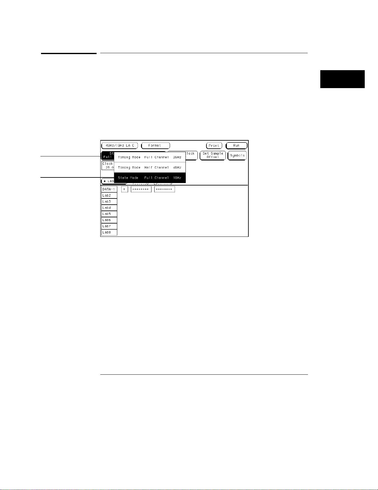
Acquisition mode
field
State acquisition
mode selection
The Format Menu
Synchronous State Acquisition Mode
Synchronous State Acquisition Mode
The Acquisition Mode field is used to select the acquisition mode. The
acquisition mode configures which clock source is used, the channel width,
memory depth, and maximum sampling speed.
State Mode Full Channel 1 GHz
In State Mode Full Channel 1 GHz, both pods are available on all configured
cards. Memory depth is 64 Kbits per channel.
State Acquisition Mode Selection
3–3
Page 32
The Format Menu
Conventional Timing Acquisition Mode
Conventional Timing Acquisition Mode
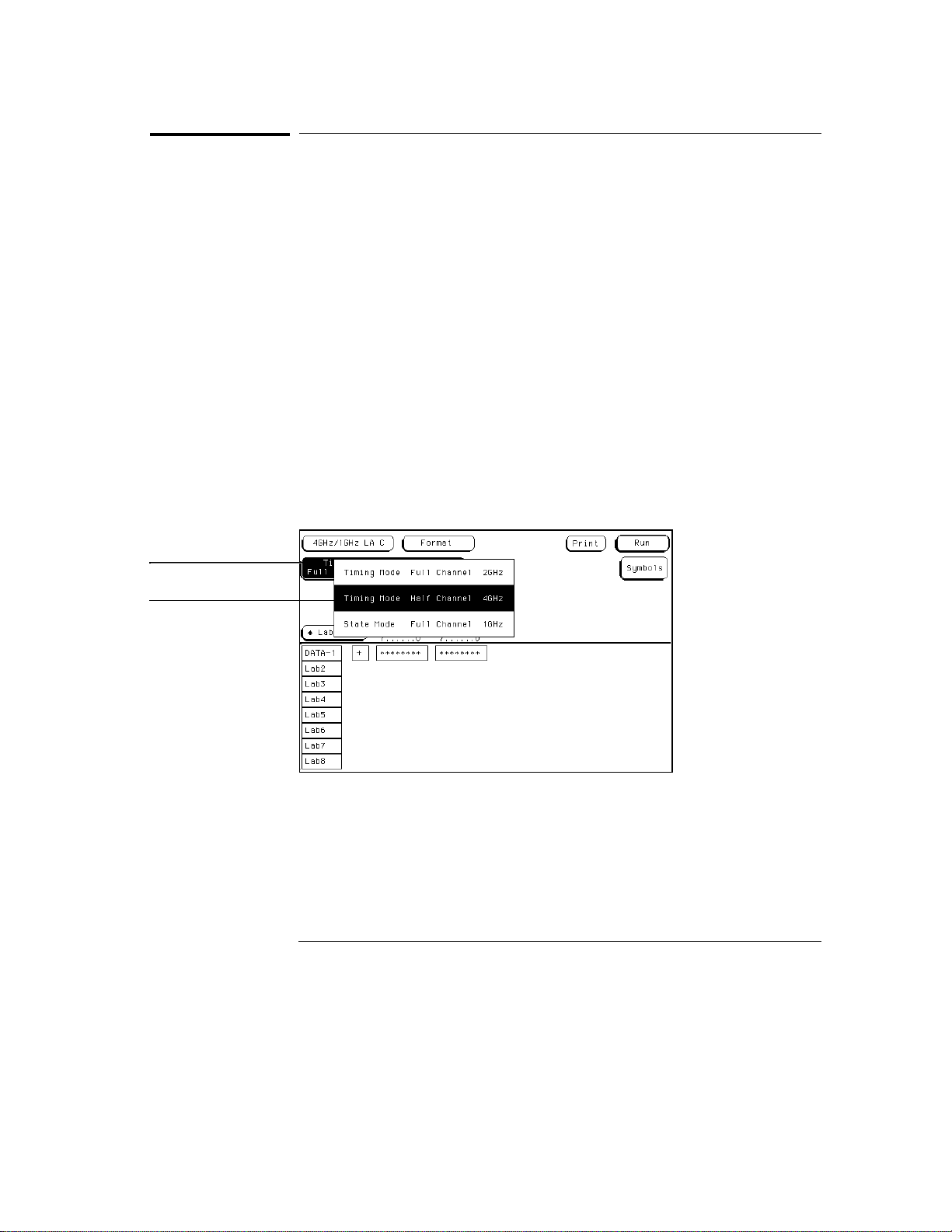
The Acquisition Mode field is used to select the acquisition mode. The
acquisition mode configures which clock source is used, the channel width,
memory depth, and sampling speed.
Timing Mode Full Channel 2 GHz
In Timing Mode Full Channel 2 GHz, both pods are available on all configured
cards. Memory depth is 64 Kbits per channel. The sampling speed in this
mode is up to 2 GHz.
Timing Mode Half Channel 4 GHz
In Timing Mode Half Channel 4 GHz, only bits 0 through 3 on all pods are
available. However, memory depth is 128 Kbits per channel. Sampling speed
in this mode is fixed at 4 GHz.
When you switch back from the half-channel mode, you are asked if you want
to restore bits 4 through 7. If you answer Yes, you restore these bits to the
target system in their previous On (assigned) or Off (not assigned) setting.
Acquisition mode
field
Timing acquisition
mode selection
Timing Acquisition Mode Selection
3–4
Page 33
The Format Menu
Select Clock Field (State Only)
Select Clock Field (State Only)
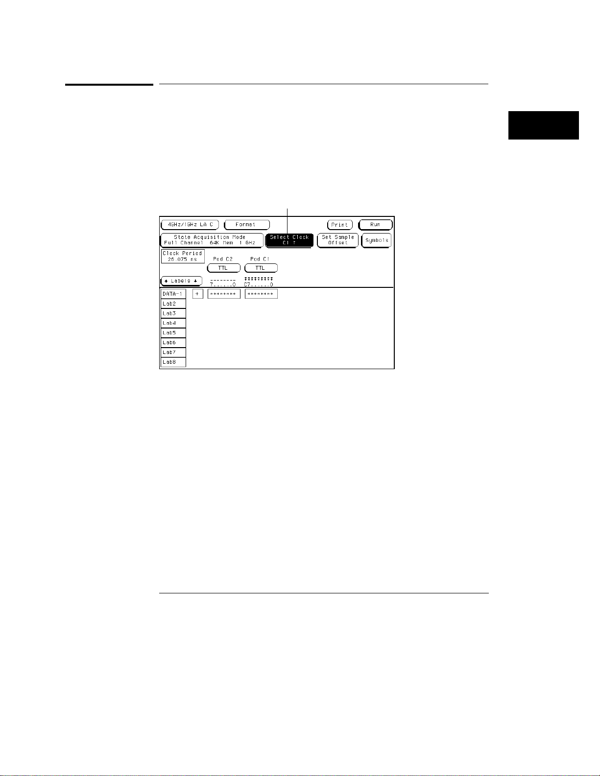
In the State Acquisition mode, the external clock is connected through pod
one on the master card. The Select Clock field accesses a selection pop-up
from which you select the edge. The edge choices are either rising or falling.
Select clock field
Clock and Edge Selection
3–5
Page 34

The Format Menu
Set Sample Offset Field (State Only)
Set Sample Offset Field (State Only)
The Set Sample Offset field is used to shift the point at which samples are
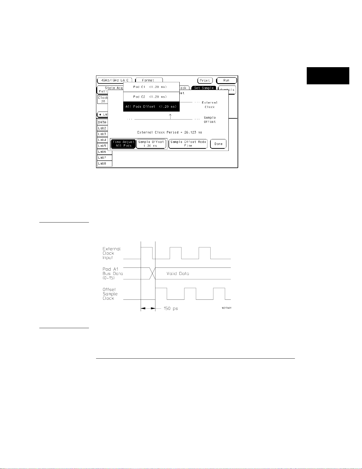
taken with respect to the external clock edge. The Format menu is the only
place where this adjustment is available.
Set sample offset
Sample offset
adjustment
Set Sample Offset Field
Sample Offset Mode
You can adjust the sample offset by using either the coarse adjustment or, if
resolution is needed, the fine adjustment.
Coarse
knob, the sample point is offset from the external clock in 200 ps
increments. The maximum offset is 5 ns. This adjustment affects all
pods. Any coarse adjustment becomes the point from which the fine
adjustment starts.
3–6
The coarse adjustment is the default mode. As you turn the
Page 35
The Format Menu
Set Sample Offset Field (State Only)
Fine
When the Sample Offset Mode field is selected, it toggles from
Coarse to Fine, and an additional Fine Adjust field becomes available.
Use this field to select each individual pod, or All pods adjusted together.
Fine Adjustment Fields
Example
In the Fine mode, you can offset the sample point of individual pods an
additional 250 ps from the point of course adjustment within the 5 ns range.
Fine adjustments are in 50 ps increments.
Your valid data appears 150 ps after the rising edge of the external clock, so
offset the sample point by 150 ps.
Offsetting the External Clock
3–7
Page 36
The Format Menu
Pod Threshold Field
Pod Threshold Field
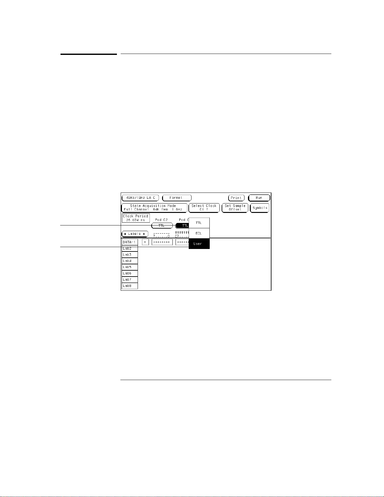
The pod threshold field is used to set a voltage level which the data must
cross before the analyzer recognizes and displays it as a change in logic
levels. You specify a threshold level for each pod. The level specified for the
master pod, which includes the clock, is also assigned to the clock.
TTL
When TTL is selected as the threshold level, the data signals must
cross +1.5 volts.
ECL
When ECL is selected as the threshold level, the data signals must
cross −1.3 volts.
Pod threshold field
Pod threshold selection
menu
USER
must cross a user selectable value between −5.0 volts to +5.0 volts.
Pod Threshold Field
When USER is selected as the threshold level, the data signals
3–8
Page 37
The Format Menu
Label Polarity Fields
Label Polarity Fields
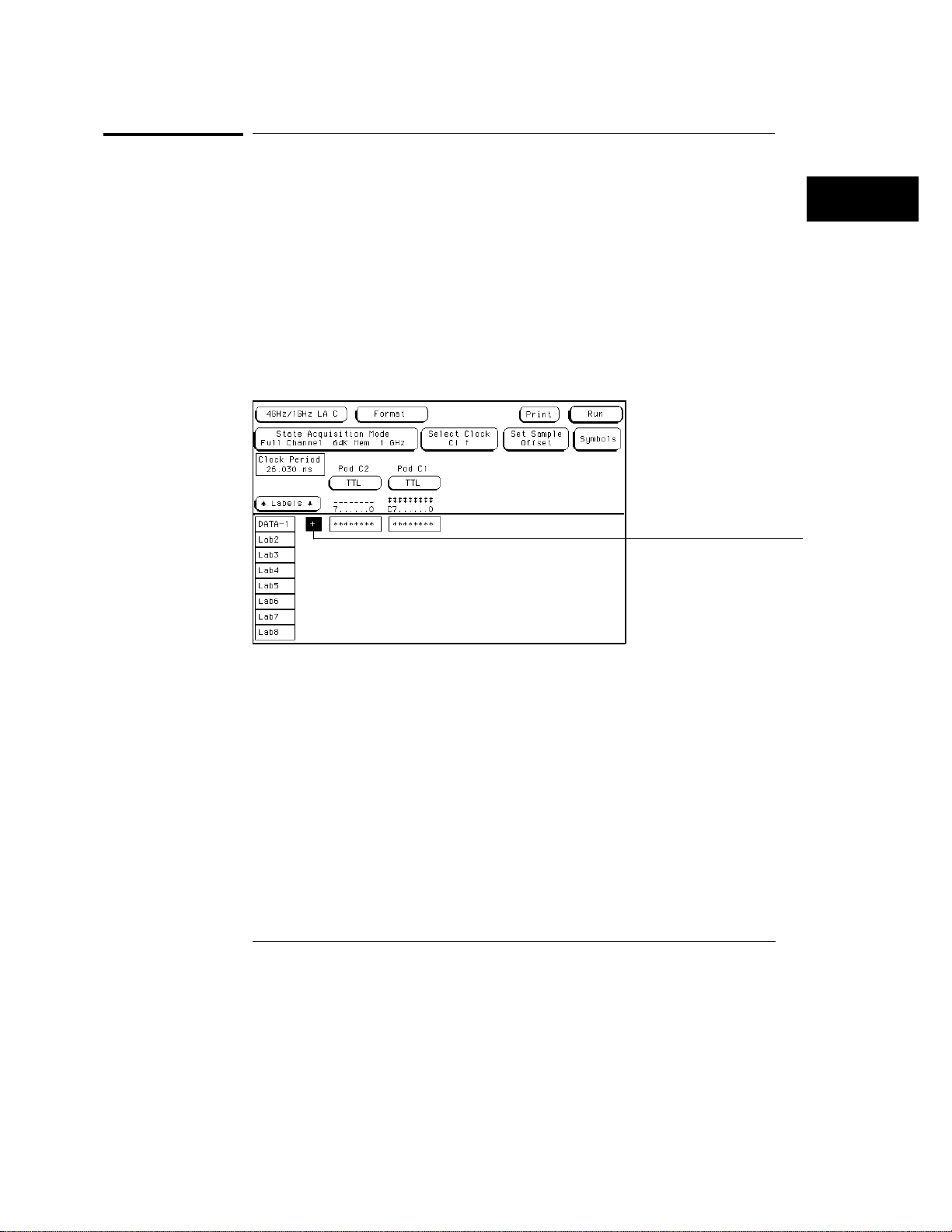
The Label Polarity fields are used to assign a polarity to each label. The
default polarity for all labels is positive ( + ). You change the label polarity by
selecting the polarity field, which toggles the polarity between positive ( + )
and negative ( − ).
When the polarity is inverted, all data and bit pattern specific configurations
used for identifying, triggering, or storing data reflect the change of polarity.
In a timing analyzer with the data inverted, the waveform display does not
change.
Polarity Field
Polarity field
3–9
Page 38
The Format Menu
Bit Assignment Fields
Bit Assignment Fields
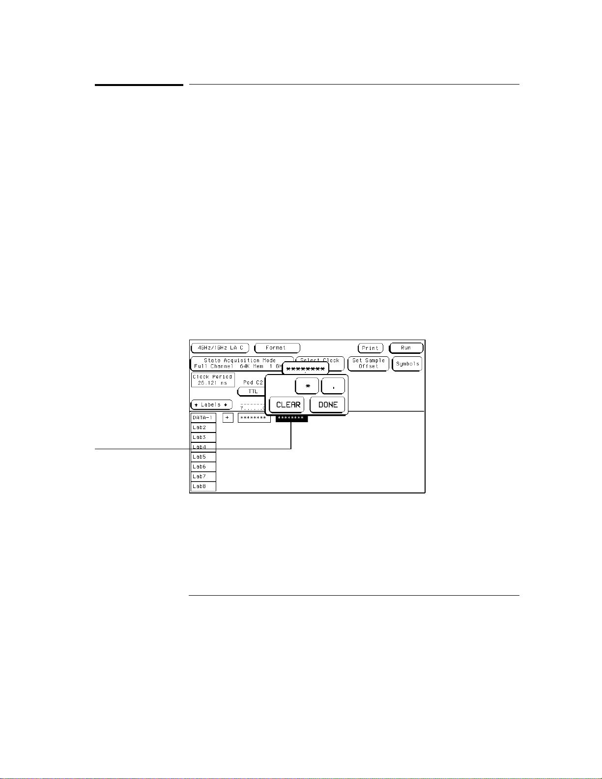
The bit assignment fields are used to assign bits (channels) to labels. The
convention for bit assignment is as follows:
* (asterisk) indicates assigned bit.
•
(period) indicates unassigned bit.
.
•
To change a bit assignment, select the bit assignment field and move the
cursor to the bit you want to change, then select an asterisk or a period.
When the bits are assigned as desired, close the pop-up. The screen displays
the new bit assignment.
Above each column of bit assignment fields is a bit reference line that shows
you the clock bit, and the eight data bits with the left bit numbered 7 and the
right bit numbered 0. This bit reference line helps you know exactly which
bits are connected by displaying activity indicators when a proper connection
from the probe is recognized.
See Also
Bit assignment field
"Activity Indicators," later in this chapter, for more information on how to
read the activity indicator display.
Bit Assignment Field
3–10
Page 39
The Format Menu
Bit Assignment Fields
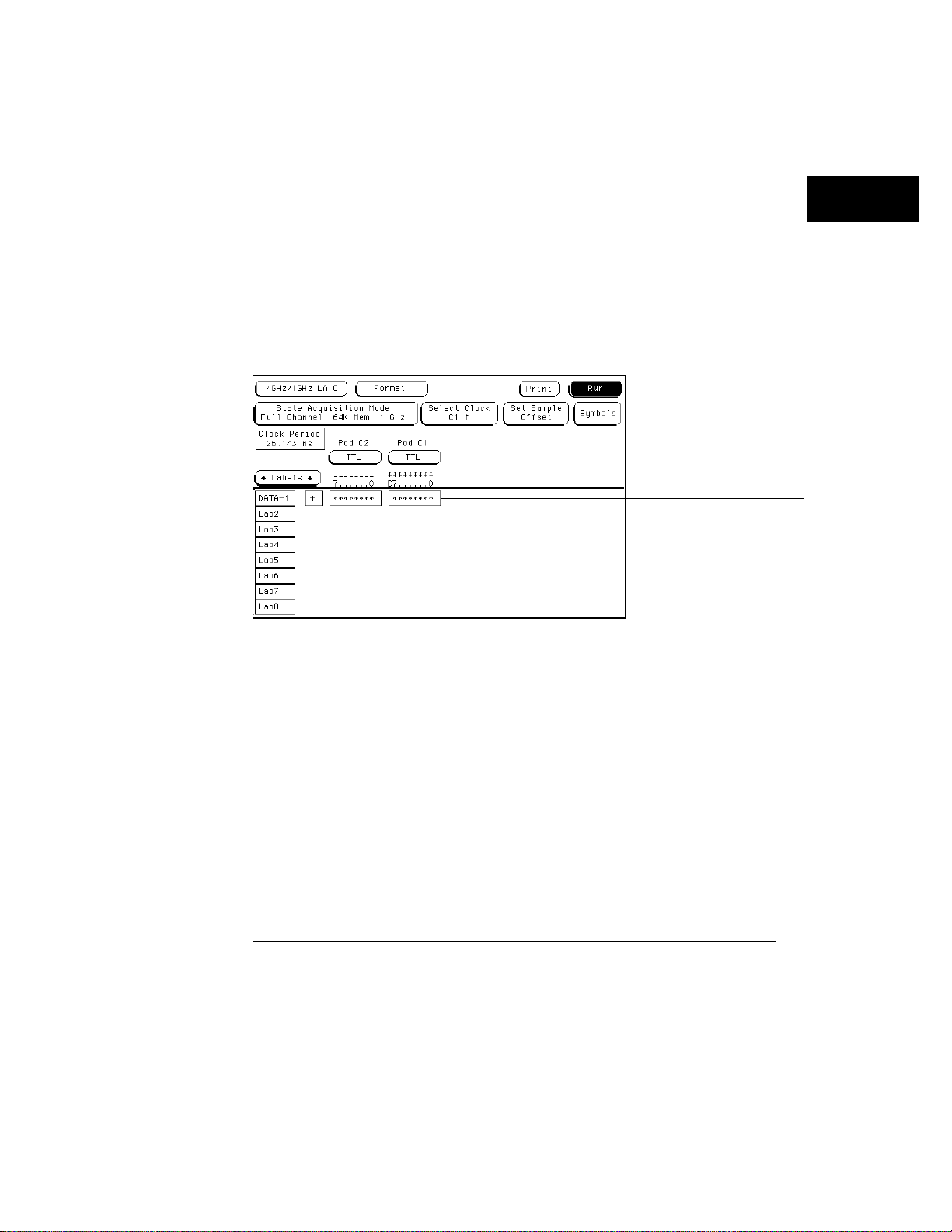
Labels may have from 1 to 32 channels assigned to them. If you try to assign
more than 32 channels to a label, the logic analyzer will beep, indicating an
error, and a message will appear at the top of the screen telling you that 32
channels per label is the maximum.
Channels assigned to a label are numbered from right to left by the logic
analyzer. The least significant assigned bit on the far right is numbered 0, the
next assigned bit is numbered 1, and so on. Since 32 channels can be
assigned to one label at most, the highest number that can be given to a
channel is 31.
Although labels can contain split fields, assigned channels are always
numbered consecutively within a label.
Assigned Channels Example
Assigned Channels
3–11
Page 40
The Format Menu
Activity Indicators
Activity Indicators
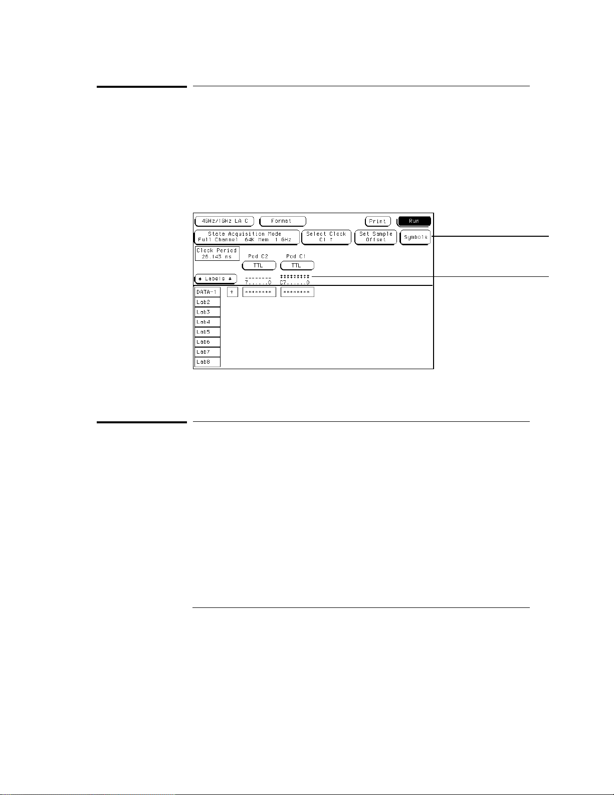
When the logic analyzer is properly connected to an active target system, you
see either a high level dash, a low level dash, or a transitional arrow in the
Activity Indicator displays for each pod probe. These indicators are very
useful in showing proper probe connection and that the logic levels are as
expected according to the threshold level setting. The Activity Indicators are
not displayed during an acquisition.
Symbols field
Activity Indicators
See Also
Activity Indicators
Symbols Field
Symbols are used in place of ambiguous data values in data listings. A
custom symbol name, relevant to the measurement, can be easily spotted in a
long list of data.
"Symbols Assignment" chapter in the Common Module Operations section of
HP 16500 Logic Analysis User’s Reference
the
assigning symbols.
3–12
for complete information on
Page 41

4
The Trigger Menu
Page 42
The Trigger Menu
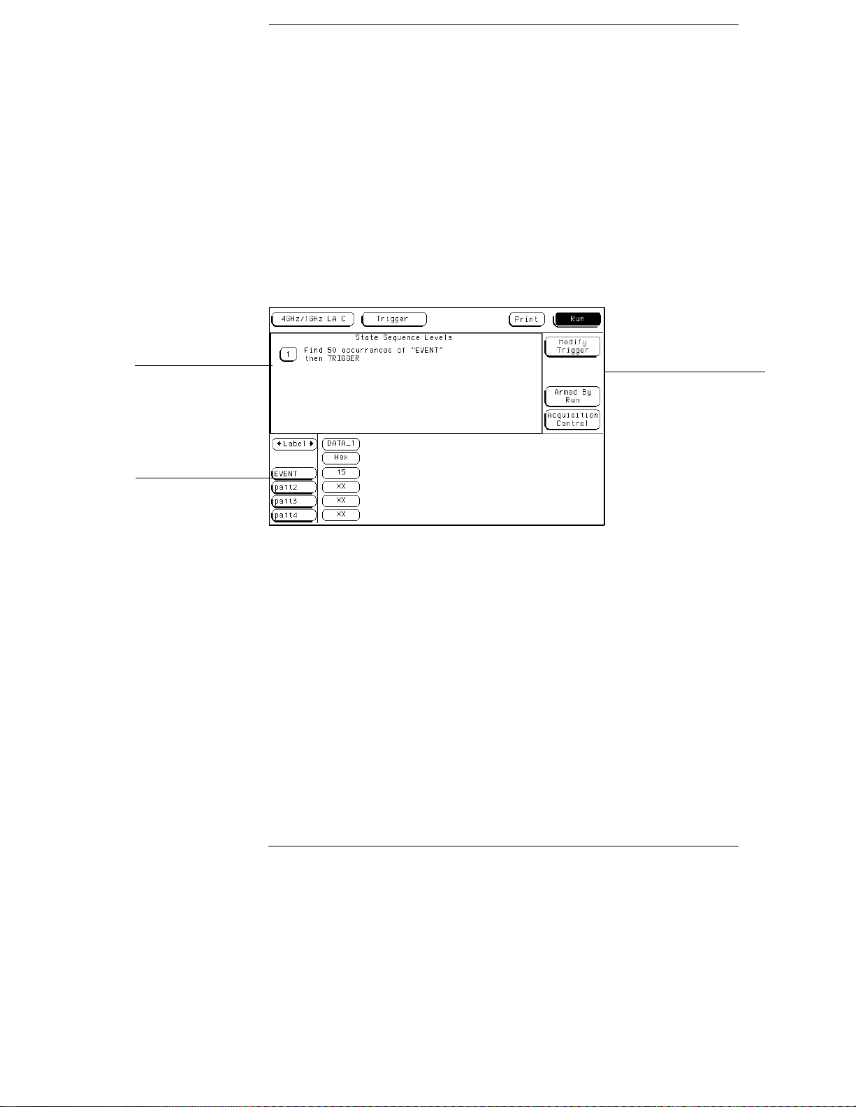
The Trigger menu is used to configure when the analyzer triggers, and
what the analyzer triggers on. In addition, within the Acquisition
Control function, prestore and poststore requirements are set. The
Trigger menu is divided into three areas, each dealing with a different
area of general operation.
Sequence levels area
Resource terms area
Control area
Trigger Menu Areas
4–2
Page 43

The Trigger Menu
Sequence Levels
The sequence levels area is where you view the sequence levels
currently used in the trigger specification. From this area you can
also access each individual level for trigger modifications.
Resource Terms
The resource terms area is where you assign values to the
user-definable resource terms. These terms take the form of bit
patterns and edges. From this area, you also make changes to the
default term names.
Control Area
The acquisition control area is where you define any external trigger
control and at what point within acquisition memory the data storage
begins.
By using resource terms, timers, and occurrence counters in the
predefined trigger macros, you easily position the data acquisition in
the data stream where you want. In addition, by using prestore and
poststore control, you use the available memory efficiently.
4–3
Page 44

Trigger Sequence Levels
Sequence levels control when the analyzer triggers, what the analyzer
triggers on, and where trigger is located in the collected data. By
using sequence levels, you can create a sequence of instructions for
the analyzer to follow. As the sequence levels are executed by the
analyzer, all subsequent branching and sequence flow is directed by
the statements within the sequence levels. The path taken resembles
a flow chart, and the end result is the desired trigger point.
A trigger sequence is made up of trigger macros, user-defined
sequence levels, or a combination of both. Both the predefined
macros and user-defined sequence instructions may contain timers,
occurrence counters, and resource terms representing edges and bit
patterns. The analyzer has up to 4 sequence levels available.
Sequence Level Types
Constructing sequence statements using the trigger macros or
user-defined statements will result in two different kinds of sequence
levels.
When predefined trigger macros are used, more than one of the
available four sequence levels may be required for a single macro.
The exact number of internal levels required per macro is shown
within the macro library list.
When the user-mode is used, all four sequence levels are available.
However, sequence levels are used up one level at a time.
Even though you may use multiple sequence levels when using trigger
macros, macros are easier to use, and may be the most efficient way
to construct a trigger specification.
4–4
Page 45
The Trigger Menu
Editing Sequence Levels
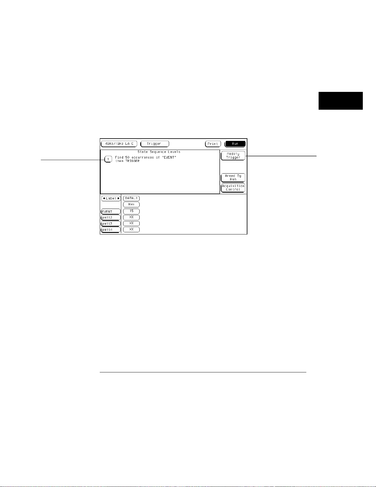
Since constructing a trigger specification may be an iterative process,
editing sequence levels may become the same kind of iterative process.
The higher level editing, such as adding or deleting entire sequence
levels, is done using the Modify Trigger field in the main Trigger
menu. You can also enter any existing sequence level from the Modify
Trigger field. Another way of editing a specific sequence level is to
select the sequence level number field.
Sequence level number
Modify trigger
Accessing Sequence Levels
Once you are in any sequence level, you configure the sequence
statement using predefined macro statements or user-defined
statements. All appropriate resource terms appear in pop-up
selection lists after any of the assignment fields within a sequence
level are selected.
4–5
Page 46
The Trigger Menu
Modify Trigger Field
Modify Trigger Field
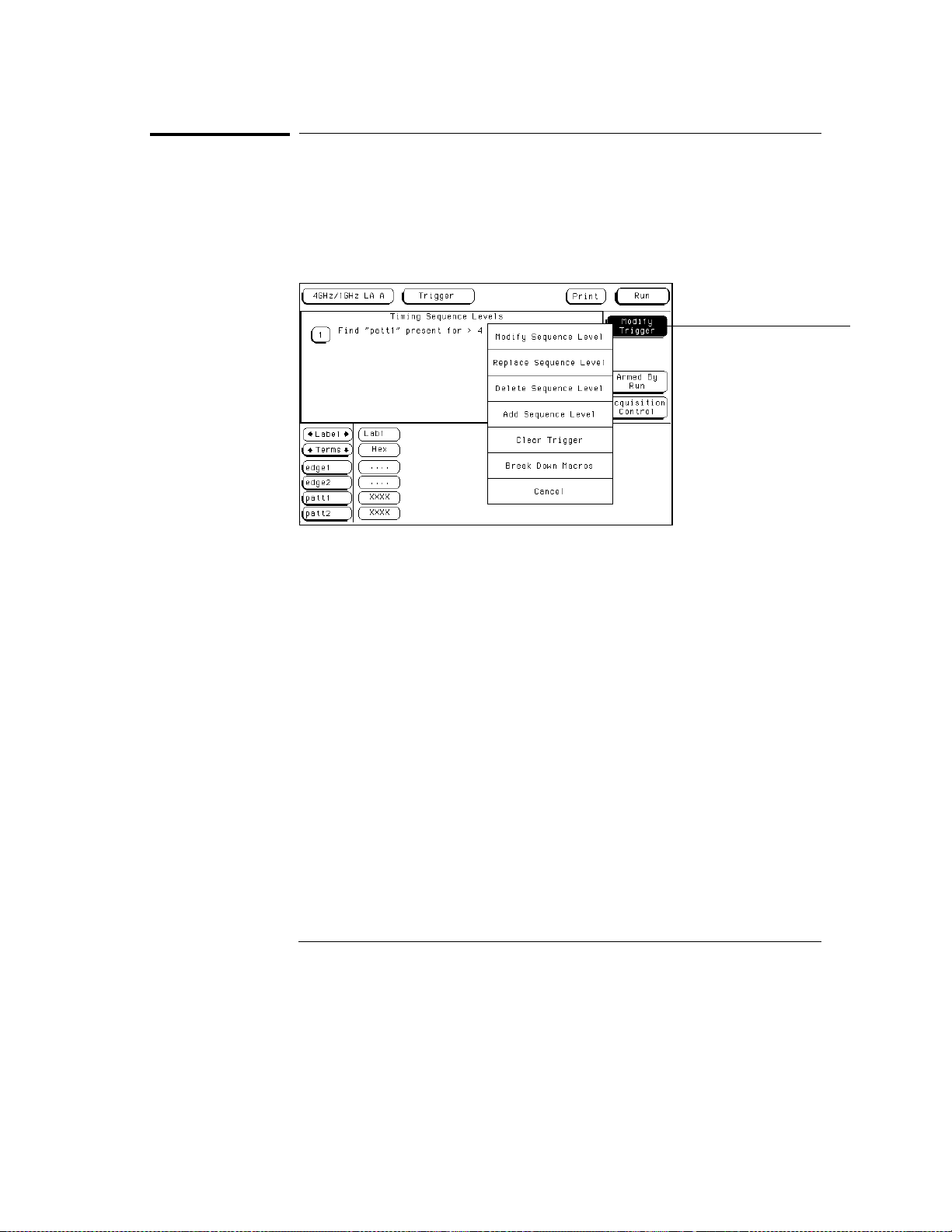
The Modify Trigger field accesses a selection menu with choices that allow
you to modify the statements of any single sequence level. In addition, other
high level actions can be accessed, like global clearing of existing trigger
statements, and adding or deleting sequence levels.
Modify Trigger field
Modify Trigger Menu
Modify Sequence Level
If there is more than one sequence level assigned, you are asked which level
to modify. Once in the desired sequence level, make all appropriate resource
changes, then select Done.
Replace Sequence Level
If there is more than one sequence level assigned, you are asked which level
to replace. When you replace a level, you pick a new macro or user-level, and
it then replaces the old one. You then assign the appropriate resource in the
new level.
4–6
Page 47

The Trigger Menu
Modify Trigger Field
Delete Sequence Level
If there is more than one sequence level assigned, you are asked which level
to delete.
Add Sequence Level
By default you have one sequence level available at power up. When you add
sequence levels, you are given the choice of inserting them before or after a
sequence level.
Clear Trigger
The Clear Trigger field accesses a selection menu used to clear any
user-defined values within the trigger specification or within the resource
terms list.
Clear All
and resource term names back to their default values.
Clear Sequence Levels
assignment fields in the sequence levels to their default values. Any
custom names assigned to the resource terms will remain.
Clear Resource Terms
all assignment fields for the resource terms back to their default values.
Clear Resource Term Names
resets all custom names assigned to the resource terms back their default
values.
The Clear All option clears sequence levels, resource terms,
The Clear Sequence Levels option resets all
The Clear Resources Terms option will reset
The Clear Resource Term Names option
4–7
Page 48

The Trigger Menu
Modify Trigger Field
Break Down Macros / Restore Macros
When a macro is broken down, the contents of that macro are displayed in
long form used in a user-defined sequence type. If the macro uses two
internal levels, both levels are separated out and displayed in the sequence
level area of the Trigger menu.
Once the macros in your trigger specification are broken down, the Break
Down Macros field changes to Restore Macros. Use the Restore Macros field
to restore all macros to their original structure. While in a broken down form,
you can change the structure. However, when the macros are restored, all
changes are lost and any branching that is part of the original structure is
restored.
Use the Break Down Macros if you want to view a particular macro part in its
long form to see exactly what flow the sequencer is following. There may be a
custom trigger specification that requires a modification in the macro’s long
form.
When a macro is broken down, you see the macro in its long form
User-defined sequence type. This means you have all the resource
assignment fields and branching options available. For information on the
assignment fields, branching, occurrence counters, and time duration
function, refer to the section, "Creating a User-Level", found later in this
chapter.
4–8
Page 49
Pre-defined Trigger Macros
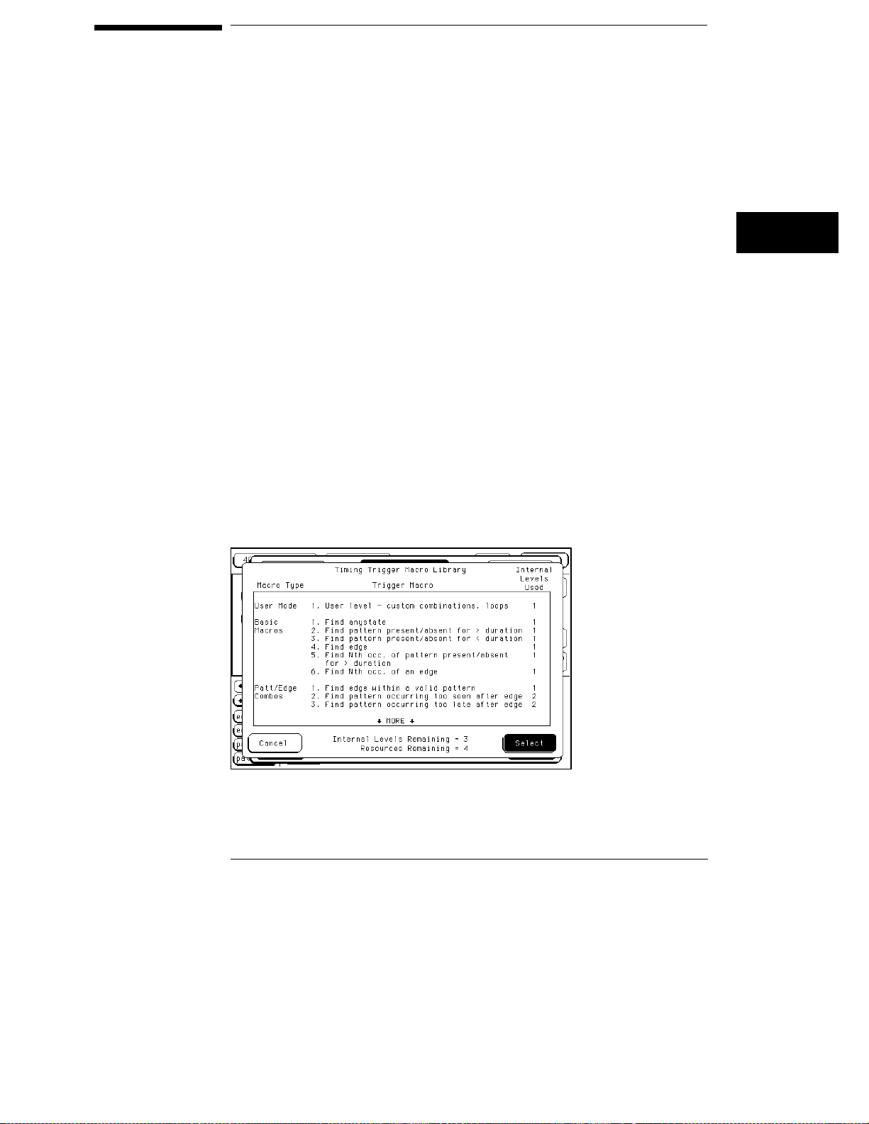
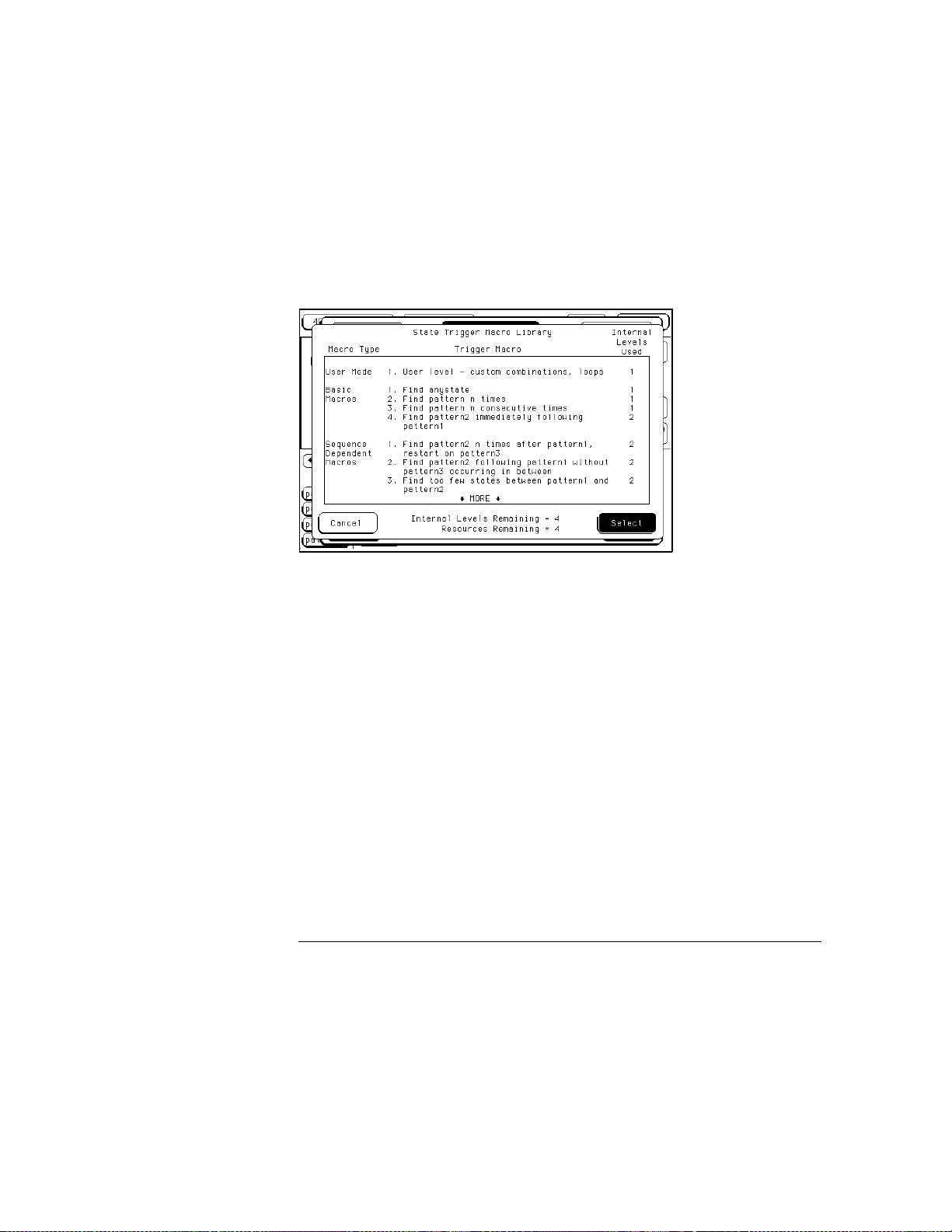
Both the state and timing acquisition modes have a macro library
containing predefined trigger macros. Depending on which
acquisition mode you are using, you get the corresponding library.
Each macro will require at least one sequence level, and in some
cases, may require multiple levels. Other than one sequence level
being followed by another, macro levels do not branch out of this
order. However, macros can be branched to, by combining a
user-defined level with a macro level.
Timing Trigger Macro Library:
• User Mode (user-defined macro)
• Basic Macros
• Pattern/Edge Combination Macros
• Setup/Hold Violation Macros
• Time Violation Macros
• Delay Macros
Timing Trigger Macro Library
4–9
Page 50
The Trigger Menu
Modify Trigger Field
State Trigger Macro Library:
• User Mode (user-defined macro)
• Basic Macros
• Sequence Dependent Macros
• Time Violation Macros
• Delay Macros
State Trigger Macro Library
4–10
Page 51
The Trigger Menu
Using Macros to Create a Trigger Specification
Using Macros to Create a Trigger Specification
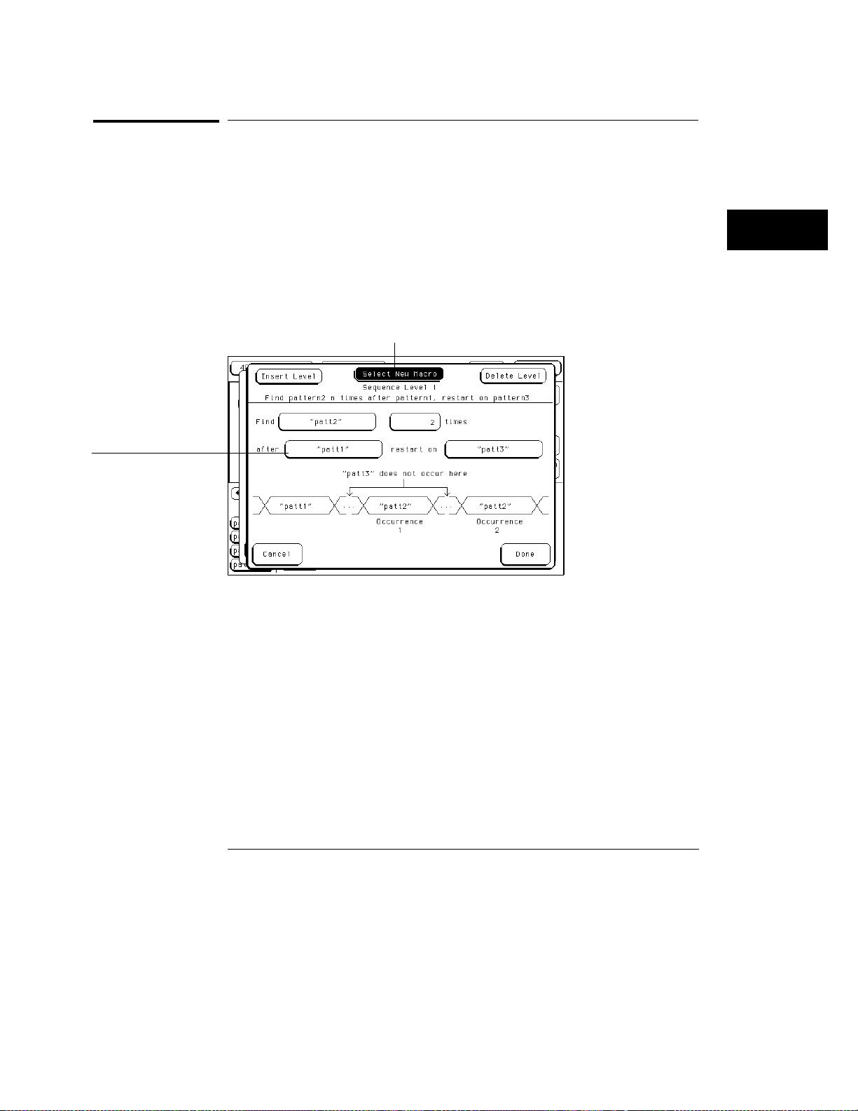
To configure a trigger specification using trigger macros, follow the
procedure below.
1
From the Trigger menu, enter the desired sequence level through the
Modify Trigger field, or by selecting a sequence level number.
See Also
Assignment field
"Editing Sequence Levels" and "Modify Trigger Field" found earlier in this
chapter for information on accessing levels.
2
From within the sequence level, select the Select New Macro field.
Select new macro field
Select New Macro Field
3
Scroll and highlight the macro you want, then select the Select field.
4
Select the appropriate assignment fields and insert the desired
predefined resource terms, numeric values, and other parameter
fields required by the macro. Select the Done field.
See Also
"Resource Terms" found later in this chapter for information on using
predefined resource terms.
4–11
Page 52

The Trigger Menu
Timing Trigger Macro Library
Timing Trigger Macro Library
The following list contains all the macros in the Timing Trigger Macro
Library. They are listed in the same order as they appear onscreen.
User Mode
Basic Macros
User level - custom combinations, loops
The User level is a user-definable level. This level offers low level
configuration and uses one internal sequence level.
1. Find anystate n times
This macro becomes true when the first state it sees appears "n" times. It
uses one internal sequence level.
2. Find pattern present/absent for > duration
This macro becomes true when it finds a designated pattern that has been
present or absent for greater than or equal to the set duration. It uses one
internal sequence level.
3. Find pattern present/absent for < duration
This macro becomes true when it finds a designated pattern that has been
present or absent for less than the set duration. It uses one internal
sequence level.
4. Find edge
This macro becomes true when the designated edge is seen. It uses one
internal sequence level.
5. Find Nth occurrence of pattern present/absent for > duration
This macro becomes true when it finds the Nth occurrence of a pattern that
has been present or absent for greater than or equal to the set duration.
Each valid pattern occurrence is only counted once, even though the same
occurrence may be valid for multiple sample clocks. It uses one internal
sequence level.
4–12
Page 53

The Trigger Menu
Timing Trigger Macro Library
6. Find Nth occurrence of an edge
This macro becomes true when it finds the designated occurrence of a
designated edge. It uses one internal sequence level. The 500 MHz trigger
sequencer may not count edges captured closer than 2 ns apart.
Pattern/Edge
Combinations
Setup/Hold
Violations
1. Find edge within a valid pattern.
This macro becomes true when a selected edge type is seen within the time
window defined by a designated pattern. It uses one internal sequence level.
2. Find pattern occurring too soon after edge
This macro becomes true when a designated pattern is seen occurring within
a set duration after a selected edge type is seen. It uses two internal
sequence levels.
3. Find pattern occurring too late after edge
This macro becomes true when one selected edge type occurs, and for a
designated period of time after that first edge is seen, a pattern is not seen
for a designated time period. It uses two internal sequence levels.
1. Find setup or hold violation
This macro becomes true when there is a change on a selected group of
channels which violates the specified setup or hold time criteria with respect
to a selected edge. It uses two internal sequence levels.
2. Find setup or hold violation clocked by an edge within a valid
pattern
This macro becomes true when either a designated setup or a hold criterion
is violated on a selected group of channels which are being clocked by a
selected edge which appears within a designated pattern. It uses two
internal sequence levels.
3. Find setup or hold violation clocked by a pattern/pulse
This macro becomes true when there is a change on a selected group of
channels which violates the specified setup or hold time criteria with respect
to a selected pattern. It uses three internal sequence levels.
4–13
Page 54

The Trigger Menu
Timing Trigger Macro Library
Time Violations
Delay
1. Find two edges too close together
This macro becomes true when a second selected edge is seen occurring
within a designated period of time after the occurrence of a first selected
edge. It uses two internal sequence levels.
2. Find two edges too far apart
This macro becomes true when a second selected edge occurs beyond a
designated period of time after the first selected edge. It uses two internal
sequence levels.
3. Find width violation on a pattern/pulse
This macro becomes true when the width of a pattern violates designated
minimum and maximum width settings. It uses one internal sequence level.
1. Wait t seconds
This macro becomes true after a designated time period has expired. It uses
one internal sequence level.
4–14
Page 55

The Trigger Menu
State Trigger Macro Library
State Trigger Macro Library
The following list contains all the macros in the State Trigger Macro Library.
They are listed in the same order as they appear onscreen.
User Mode
Basic Macros
Sequence
Dependent macros
User level - custom combinations, loops
The User level is a user-definable level. This level offers low-level
configuration and uses one internal sequence level.
1. Find anystate n times
This macro becomes true when the first state it sees appears n times. It uses
one internal sequence level.
2. Find pattern n times
This macro becomes true when it sees a designated pattern occurring a
designated number of times consecutively or nonconsecutively. It uses one
internal sequence level.
3. Find pattern n consecutive times
This macro becomes true when it sees a designated pattern occurring a
designated number of consecutive times. It uses one internal sequence level.
4. Find pattern 2 immediately following pattern 1
This macro becomes true when the first designated pattern is seen
immediately followed by a second designated pattern. It uses two internal
sequence levels.
1. Find pattern 2 "n" times after pattern 1, before pattern 3 occurs
This macro becomes true when it first finds a designated pattern 1, followed
by a selected number of occurrences of a designated pattern 2. In addition, if
a designated pattern 3 is seen anytime while the sequence is not yet true, the
sequence starts over. If pattern 2’s "nth" occurrence is coincident with
pattern 3, the sequence starts over. It uses two internal sequence levels.
4–15
Page 56

The Trigger Menu
State Trigger Macro Library
2. Find too few states between pattern 1 and pattern 2.
This macro becomes true when a designated pattern 1 is seen, followed by a
designated pattern 2, and with less than a selected number of states
occurring between the two patterns. It uses two internal sequence levels.
3. Find too many states between pattern 1 and pattern 2.
This macro becomes true when a designated pattern 1 is seen, followed by at
least a selected number of states, then followed by a designated pattern 2. It
uses two internal sequence levels.
Time Violations
Delay
1. Find pattern 2 occurring too soon after pattern 1
This macro becomes true when a designated pattern 1 is seen, followed by a
designated pattern 2, and with less than a selected time period occurring
between the two patterns. It uses two internal sequence levels.
2. Find pattern 2 occurring too late after pattern 1
This macro becomes true when a designated pattern 1 is seen, followed by at
least a selected time period, before a designated pattern 2 occurs. It uses
two internal sequence levels.
1. Wait n external clock states
This macro becomes true after a designated number of user clock states have
occurred. It uses one internal sequence level.
4–16
Page 57

The Trigger Menu
Creating a User Level
Creating a User Level
Before you begin to program a trigger specification using user-defined
sequence levels, consider that in most cases one of the trigger macros will
work.
A trigger macro library is available with pre-defined sequence statements
already built for you. By using the trigger macros you can quickly form a
trigger specification that contains all the steps required to trigger at the
desired point. Simply select the macro and assign values to the resource
terms.
However, if you need to configure a user-defined sequence level to
accommodate a specific condition, or you prefer to construct a trigger
specification from scratch, the following information and examples will help
guide you conceptually through the task.
See Also
See Also
"Pre-defined Trigger Macros" found earlier in this chapter for complete
information on the available trigger macros for the different kinds of
measurements.
User-defined Sequence Levels
If you build your own trigger specification or modify a macro, you will use
resource terms, timers, counters, and combination terms. Each sequence
level has a "fill-in-the-blanks" type statement to start with. Depending on
what you place in the assignment fields, you may cause more assignment
fields to appear. When each assignment field is selected, a list of available
resource term choices appears.
"Resource Terms" found later in this chapter for more information on the
resource terms and how they work.
When creating a sequence statement, the typical method during a debug
operation is to first trigger on a simple pattern or edge. From that point, it
becomes an iterative process of adding or tuning sequence levels until you
consistently trigger at the desired point.
4–17
Page 58
Assignment field
The Trigger Menu
Creating a User Level
The steps in this kind of process are difficult to predict, but the general
approach is to think of each sequence level as an opportunity to direct the
analyzer’s selection process in the desired direction.
During sequence execution, the analyzer searches for a match between the
resource term value and the measurement data. When a match is seen, that
part of the sequence statement becomes true and the sequencing continues
to the next sequence level. Eventually a path of "true" resource terms leads
to your trigger command.
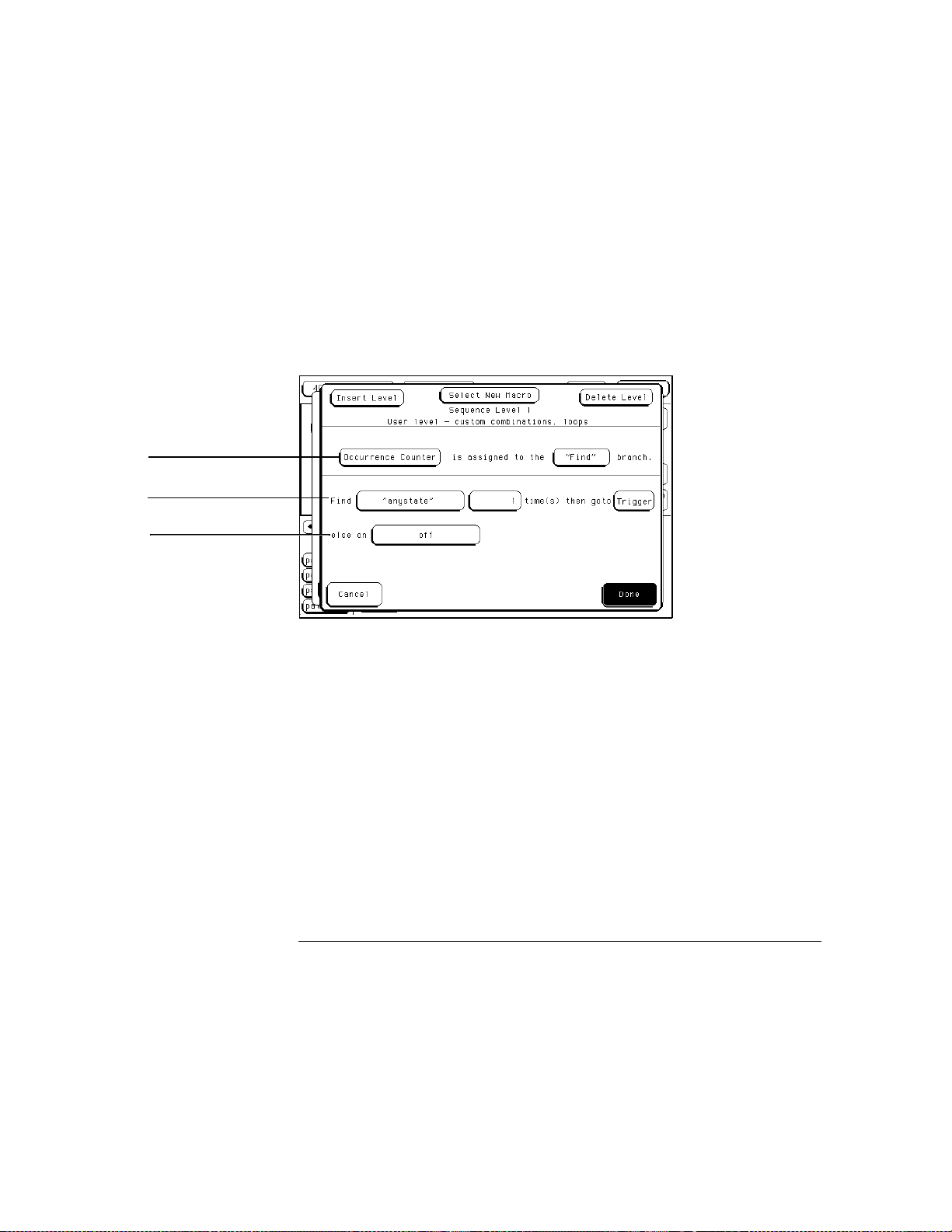
The typical User Level shown below is where you create or modify the
sequence instruction by selecting the assignment fields and inserting
resource term choices into each assignment field.
Primary "Find" branch
Secondary "else on"
branch
See Also
Sequence Level Menu
The actual resource terms available for any particular assignment field varies
on such things as the acquisition mode, if the timer or occurrence counter is
used, and how many resource terms have already been used in other levels.
"The Trigger Sequencer" section in chapter 4, "Concepts," in the
HP 16500/16501A Logic Analysis System User’s Guide
. The User’s Guide
is distinct from the User’s Reference and contains supplementary information.
4–18
Page 59

The Trigger Menu
Creating a User Level
Using Bit Patterns and Edges
Bit patterns and edges can be used by themselves or in combination. Bit
patterns are set to match specific data values, and in the timing acquisition
mode, edges are set to match specific edges of a timing pulse.
Example
Example
Example
The following statement looks for the bit pattern you assigned to the term
patt1 to occur 2 times, before it branches to sequence level 3:
patt1 2
Find
The following statement looks for a positive, negative, or either going edge
you assigned to term edge1 to occur 1 time, before it triggers:
edge1 1
Find
The following statement looks for the combination of either a bit pattern
(patt1) or an edge (edge1) to occur 1 time before it triggers:
patt1+edge1 1
Find
time(s) then goto
time(s) then goto
time(s) then goto
3
Trigger
Trigger
4–19
Page 60
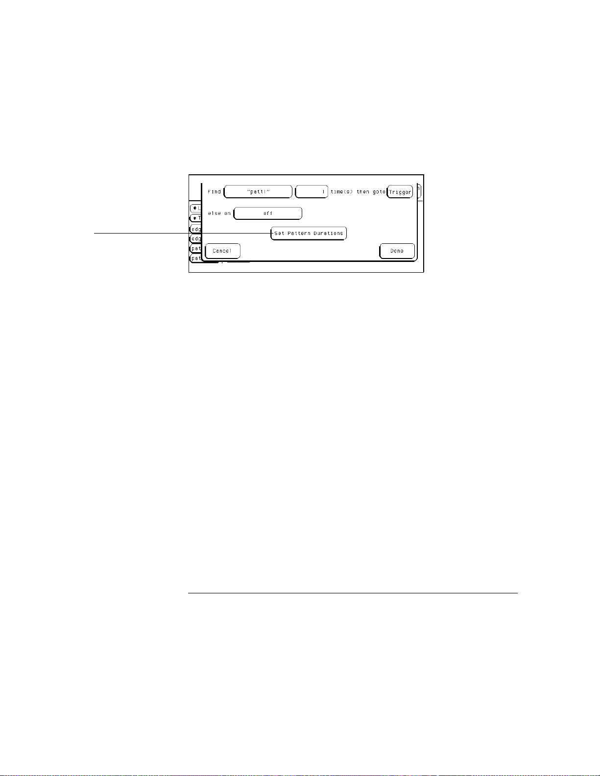
Set Pattern Duration field
The Trigger Menu
Creating a User Level
Setting Pattern Durations (Timing only)
When a bit pattern is found during a timing sequence evaluation, you can
influence when the term actually becomes "true" by assigning a time
duration. This works very similar to how the occurrence counter influences
terms. The Set Pattern Duration field appears in all levels. The duration
assignment menu is accessed by selecting the Set Pattern Duration field.
Set Pattern Duration Field at bottom of Sequence Level Menu
See Also
Pattern duration is assigned by sequence level and only to the resource terms
being used in that level. This means that you could set different durations to
the same term name in a different sequence level. However, each time you
use that same term with different duration values, and in different sequence
levels, you use up another resource. In other words, there is no difference
between using one resource term four times with different pattern durations,
and using four different resource terms once each.
"Resource Terms" section found later in this reference for more information
on resource terms definition and usage.
4–20
Page 61
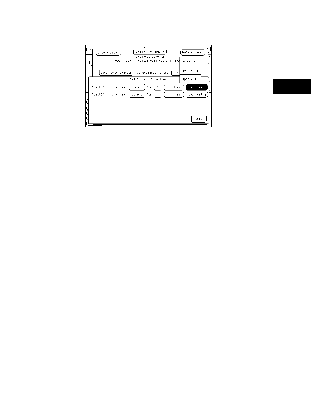
The Trigger Menu
Creating a User Level
Present/Absent field
< > field
Until exit/Upon entry/
Upon exit field
Duration Assignment Menu
Present/Absent Field
This field determines whether the resource
becomes true when the bit pattern is present or absent for the specified
time interval.
< > Field
This field allows you to choose whether the pattern duration
is longer or shorter than the specified time. When (<) is selected, the
resource is true for one clock cycle after a pattern is present/absent for
less than the duration value. When you select (<), the until exit/upon
entry/upon exit field disappears.
When (>) is selected, additional control over pattern duration becomes
available. This control allows you to pick what happens after the pattern has
been present/absent for more than the duration value.
Until exit/ Upon entry/ Upon exit Field
This part of the Set Pattern
Duration statement dictates how long the resource is true after the
pattern duration is met. The Until Exit selection keeps the resource true
from the time the duration is met, until the end of the pattern. The Upon
Entry selection makes the resource true for only one clock cycle after the
duration is met. The Upon Exit selection makes the statement true for
one clock cycle after the end of the pattern.
4–21
Page 62
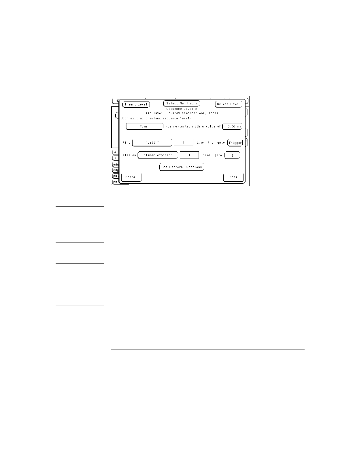
Timer/Occurrence counter
toggle field
The Trigger Menu
Creating a User Level
Using the Timer
The timer is started as the sequence level is entered. If you return to the
same sequence level again, the timer will be restarted. If you choose to use
the timer in a sequence level, the occurrence counter is not available in that
level.
Example
Example
Sequence Level Menu with Timer
The following statement assigns the Timer to count down from 4 ns when the
sequence level is entered.
Upon exiting previous sequence level:
Timer
was restarted with a value of
4 ns
The following statement tells you that if the primary "Find" branch is not
taken before the Timer expired, you will take the secondary branch to an
immediate Trigger command.
else on
Timer expired 1
time goto
Trigger
4–22
Page 63

The Trigger Menu
Creating a User Level
Using the Occurrence Counters
The occurrence counter is assigned to either the "Find" branch or the "else
on" branch. Whatever positive number you assign to the counter, the pattern
must be seen that number of times before the term becomes true.
It should be noted that in order to count occurrences of a pattern with a >
duration, the Upon Entry or Upon Exit selections should be used. In the
Until Exit mode, the occurrence counter is clocked at a 2 ns rate as long as
the resource is true, in effect acting like a duration counter.
If the "else on" branch becomes true before all specified occurrences of the
primary branch, the secondary "else on" branch is taken.
If you choose to use the occurrence counter in a sequence level, the timer is
not available in that level.
Example
The following statement assigns the Occurrence Counter to the primary
"Find" branch. Once the Occurrence Counter is assigned, a new assignment
field appears in the primary branch to set occurrences.
Occurrence Counter
patt1 3
Find
time(s) then goto
is assigned to the
"Find"
Trigger
branch
4–23
Page 64

The Trigger Menu
Creating a User Level
Branching
Each of the four sequence levels has one primary branch and one secondary
branch. If the primary branch is taken, the destination is directed by the
"Find" statement. If the secondary branch is taken, the destination is
directed by the "else on" statement. The primary branch must be used
whereas the secondary branch can be turned off.
If both branch statements are simultaneously met, the primary branch will be
taken. Both branches can be directed to any active sequence level or to the
Trigger. When the trigger is seen, sequencing is over and the poststore
counter begins counting down to zero, at which time data storage is over.
See Also
Example
"Acquisition Control" section for more information on configuring memory to
store posttrigger data.
The following statement instructs the analyzer to start the Timer as the
sequence level is entered. It then will have 8 ns to find the bit pattern you
assigned to "patt1." If it finds "patt1," then the analyzer triggers. If it doesn’t
find "patt1" in 8 ns, the sequence evaluation branches to sequence level 2.
Upon exiting previous sequence level:
Timer
patt1 1
Find
else on
Timer expired 1
was restarted with a value of
time then goto
Trigger
time goto
8 ns
2
4–24
Page 65

Resource Terms
The analyzer has four resources and one timer/counter. The four
resources can be represented by up to six resource term names,
patt1−patt4 bit patterns, and edges 1−2 (timing only). The pattern
and edge terms are used in any of the four sequence levels.
Once you assign the four resources with both a resource term name
and a value, the resources can be used either by themselves or in
combination with each other. It is possible to have up to six resource
term names assigned to different pattern and edge values, however,
you will only be allowed to insert up to four of them in the total trigger
specification.
Pattern duration is assigned per sequence level. This means that you
could assign a different duration to the same term name in a different
sequence level. However, each time you use that same term with
different duration values, you use up another resource. In other
words, there is no difference in using one resource term four times
with different pattern durations than to use all four resource terms
once.
Since the timer can operate individually within each sequence level, it
is like actually having up to four timers in the total trigger
specification. However, if you choose to use a timer, the occurrence
counter is not available in that same level. On a per-sequence level
basis, the timer/counter is either a timer or a counter, but not both. In
addition to the timer/counter, the resource terms are separated into
two groups:
• Bit Patterns Terms patt1
patt4
−
• Edge Terms 1 and 2 (Timing only)
4–25
Page 66

The Trigger Menu
Creating a User Level
Bit Patterns Terms patt1−patt4
Bit patterns with default names patt1− patt4 are available to use for
any of the four resources. Bit pattern resource terms are set to match
the numeric value or bit pattern of a group of data channels. All bits
of the pattern that are not defined as Don’t Cares (x) must match the
input data in order for a pattern to be present. Bit patterns can also
be used in a negated form (≠patt1 –
changed to a customized name that may better suit a measurement.
patt4). All term names can be
≠
Edge Terms 1 and 2 (Timing only)
Edge terms with default names edge1 and edge2 are available in the
timing acquisition mode. They can be assigned to two of the four
resources to identify a rising or falling edge, or either edge. The edge
resource is true if any of the defined bit transitions occurs.
Timer/Occurrence Counter Term
Although the timer/counter is not located with the other resource
terms, it is still considered a resource term. Because the timer/counter
works exclusively for each level it is assigned to, it will not affect any
other level of the trigger specification from a global aspect. Either a
timer or an occurrence counter may be used in each sequence level,
and it can have different values assigned in each level.
4–26
Page 67
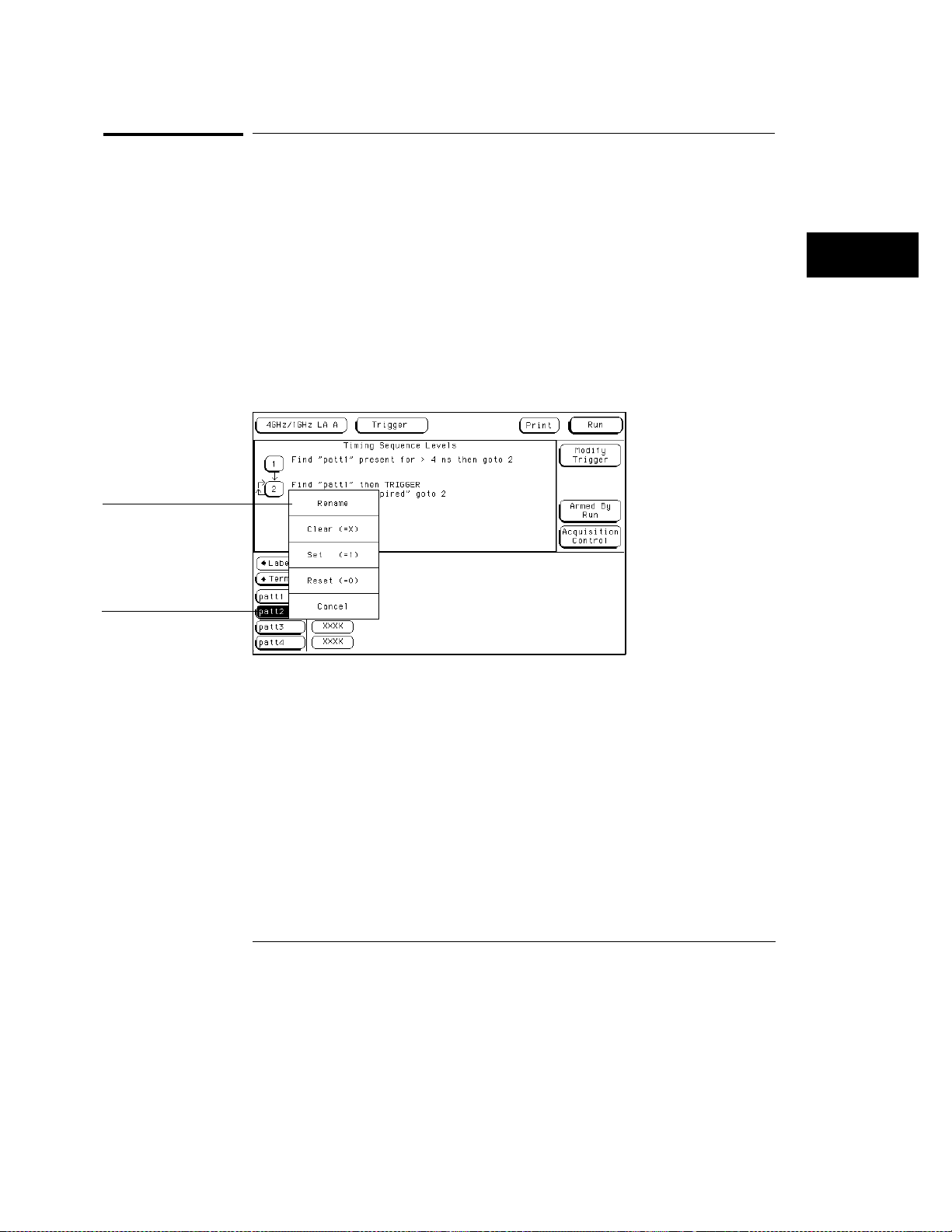
The Trigger Menu
Assigning Resource Term Names and Values
Assigning Resource Term Names and Values
The Terms field identifies the list of available resource term names within the
analyzer. The resource term names (patt1 − patt4, edge1, edge2) are default
names and can be changed if desired. The pattern and edge terms can also
have their values changed bit by bit or all at once with preset values.
Using Preset Values
When any of the individual term fields (patt1 − patt4, edge1, edge2) are
selected, a configuration menu appears. Use this configuration menu to
quickly assign the resource term to a preset value, or to assign a customized
name to the resource term.
Resource term
configuration menu
Resource term name
field
Resource Term Configuration Menu
Rename
This function accesses a keypad which you use to create a
custom name or edit the existing name for the resource term. This
function works for both pattern and edge names.
Clear (=X)
Sets the term assignment fields as follows:
In terms patt1 − patt4, the assignment field is set to all "X" (don’t cares).
In terms edge1 − edge2, the assignment field is reset to all "." (periods).
Set (=1)
Reset (=0)
Sets the pattern terms to all 1s. Not available for edge terms.
Sets the pattern terms to all 0s. Not available for edge terms.
4–27
Page 68
The Trigger Menu
Assigning Resource Term Names and Values
Setting Bit Pattern Values
Just to the right of the term name fields are the term assignment fields.
When any of the individual assignment fields are selected, a keypad appears.
Use this keypad to assign values or Don’t Cares (x).
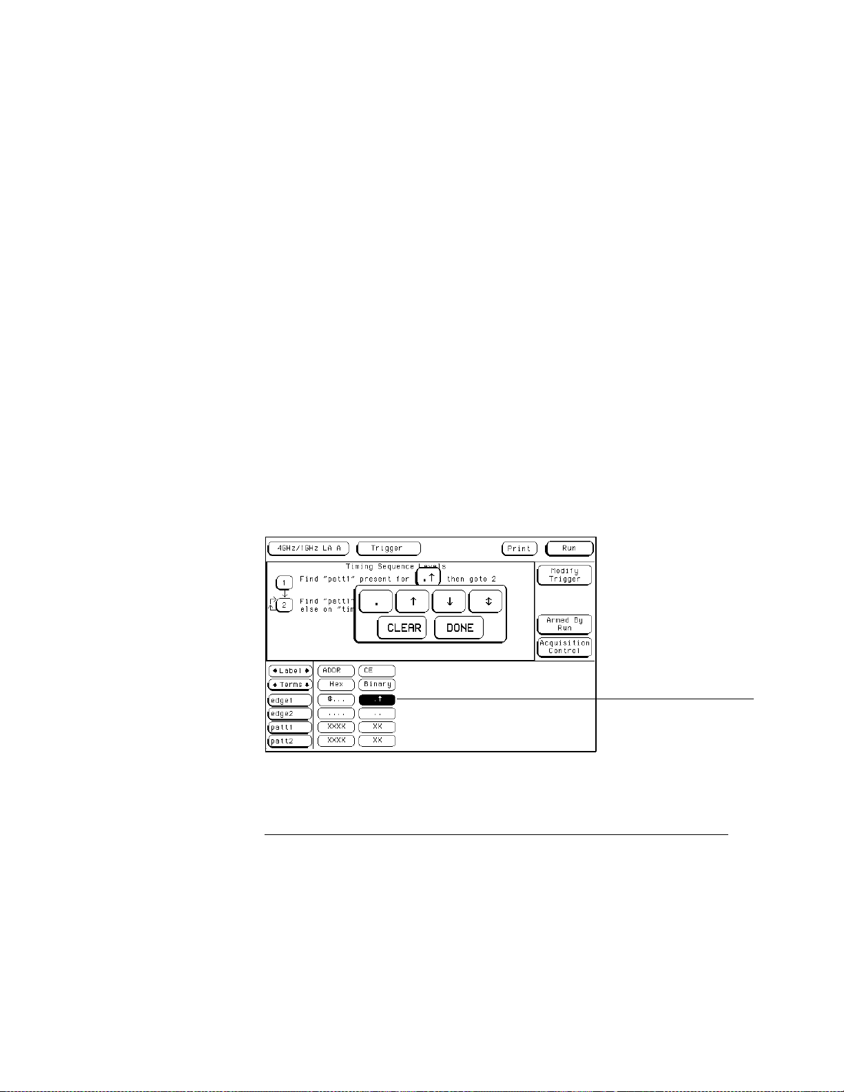
Edge Terms 1 and 2
If you want to qualify an edge, place the appropriate edge on the data
channel you are watching. When the analyzer sees an edge, the term
becomes true.
Edge terms can be used singularly or in combination with each other across
all assigned channels. When you specify an edge on more than one channel,
the analyzer ORs the edges.
The following edge choices are available for each bit:
Positive edge
•
Negative edge
•
Either positive or negative (↕)
•
Not assigned (.)
•
After the assignment menu closes, you may see "$" indicators in the
assignment field display. This symbol indicates the assignment can’t totally
be displayed in the selected base. It was assigned in another base. When
Binary is selected for the numeric base, you see the actual assignments.
(↑)
(↓)
Edge Assignment Pop-up Menu
4–28
Term assignment field
Page 69

The Trigger Menu
Assigning Resource Term Names and Values
Timer Term
Timer options are selected from within sequence levels. The timer term is
evaluated as either true or false. A true timer term lets the sequence
evaluation continue within the current statement. Because the timer works
exclusively for each level it is assigned to, it will not affect any other level or
the trigger specification from a global respect. However, each sequence level
can have its own timer with different values assigned. The timer term
options are used in the following ways:
"Timer expired"
expires.
"Timer not expired"
has not expired. Once expired, the timer term becomes false. This is
like negating the timer.
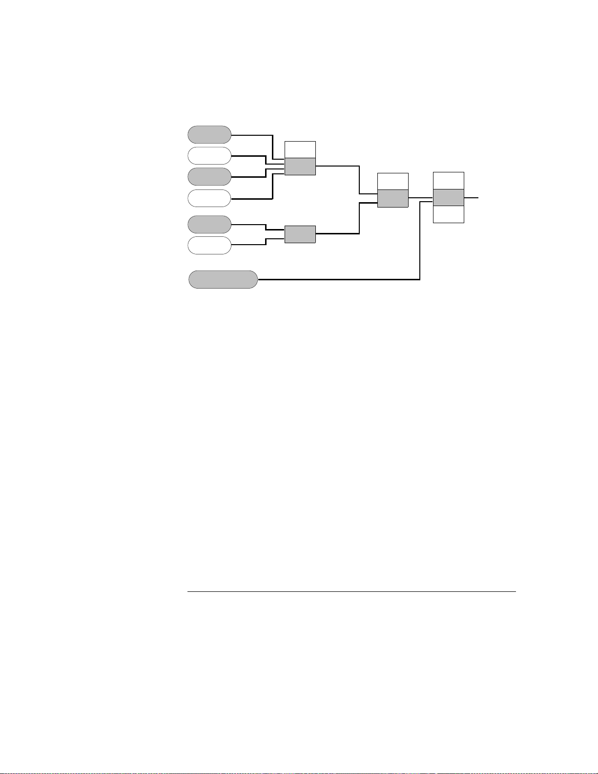
Combination of Terms
Combination terms are configured and selected from within sequence levels.
All user-defined resource terms can be combined to create complex qualifiers
that occupy a single assignment field space.
When the term assignment field is selected, and "Combination" is selected
from the pop-up selection list, a logical assignment menu appears. Use this
menu to select pre-defined resource terms as inputs to a chain of logical
operators.
The timer term becomes true when its assigned time
The timer term is true while the assigned time
4–29
Page 70
The Trigger Menu
Assigning Resource Term Names and Values
patt1
patt2
patt3
patt4
edge1
edge2
Timer_expired
Combination Term Choices
OR
AND
OR
OR
AND
OR
AND
XOR
Combination
Term
Logical operators are configured into the chain by selecting the logical
operation field. They will toggle to another choice, or, a selection list will
appear.
When the configuration process is complete, and the "Done" field is selected,
the created combination of terms is then inserted into the term assignment
field in the sequence instruction.
Build the complex term under the following conventions:
Bit patterns are ORed or ANDed to other bit patterns.
•
Edges are ORed to other edges.
•
Bit patterns are ANDed or ORed to edges.
•
Any bit pattern and edge combination is ANDed, ORed, or XORed to the
•
timer.
When the combination is placed in the assignment field, if the term is too
long to fit in the assignment field, the display is truncated.
4–30
Page 71
The Trigger Menu
Label and Base fields
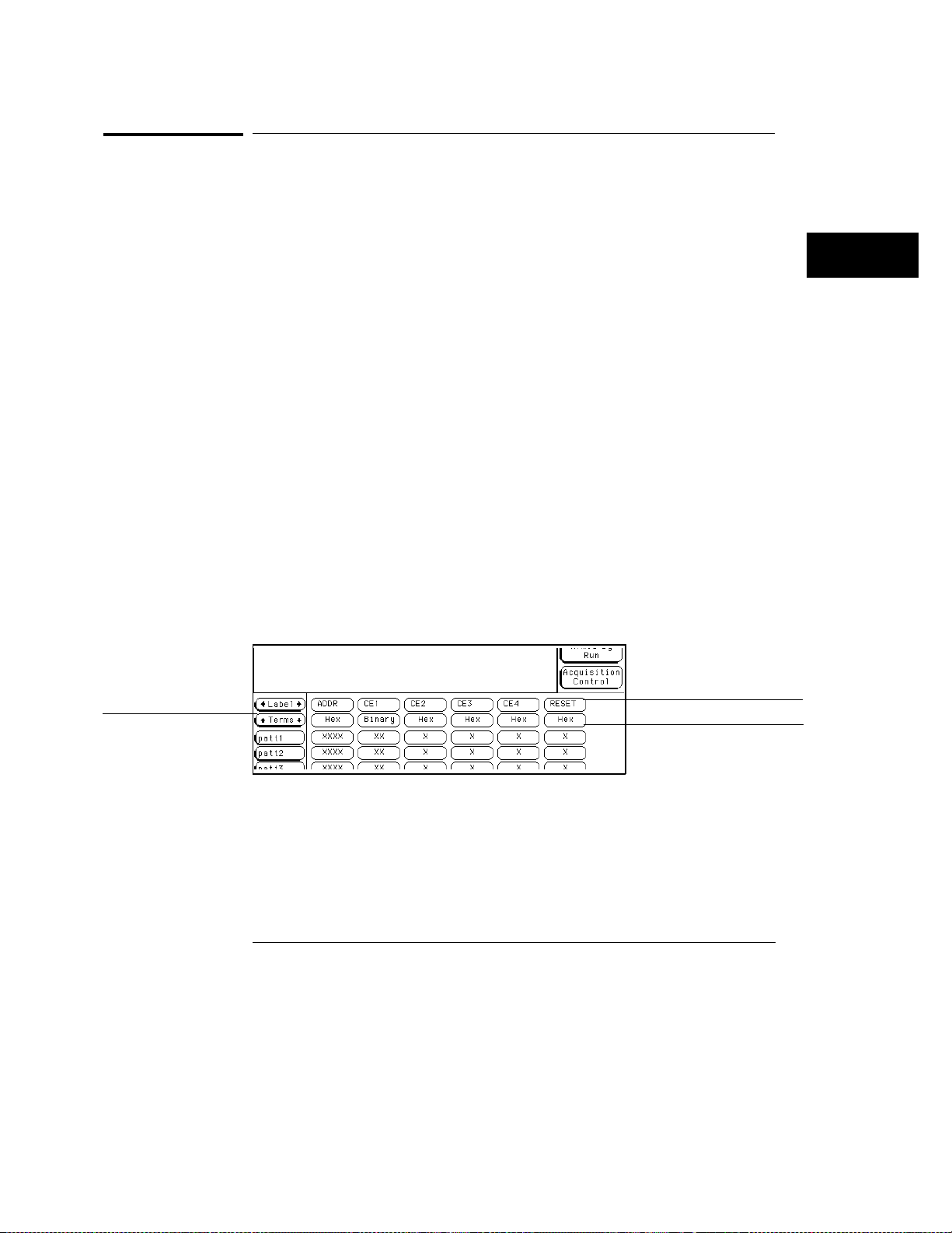
Label and Base fields
The Label and Base fields show up together in all menus except the Format
menu. When a new label is assigned, a base field is automatically assigned to
that label.
See Also
Label roll field and
Terms roll field
Label Field
Labels are displayed throughout the analyzer as they were
assigned in the Format menu. To reorder currently displayed labels in
the Trigger menu and the Specify Pattern sub-menus, select the label
you want to move, then from the selection menu that appears, choose
the label you want to switch positions with.
"Labels Assignment" chapter, in the Common Modules Operations section of
HP 16500/16501A Logic Analysis System User’s Reference.
the
Base Field
All assigned labels will have a base field. If the numeric
base is changed in a menu, the base in other menus may not change
accordingly. As an example, the base assigned to symbols is unique, as is
the base assigned in the Compare and Listing menus. The base choices
are Binary, Octal, Decimal, Hex, ASCII, Symbol, and Twos.
Label and Terms roll field
The rolling function is the same for all
items that are stored offscreen. For more information on rolling labels,
base, and pods, refer to the "Labels Assignment" chapter in the
HP 16500/16501A Logic Analysis System User’s Reference.
Label field
Base field
Detail of Trigger Menu
4–31
Page 72
Acquisition Control
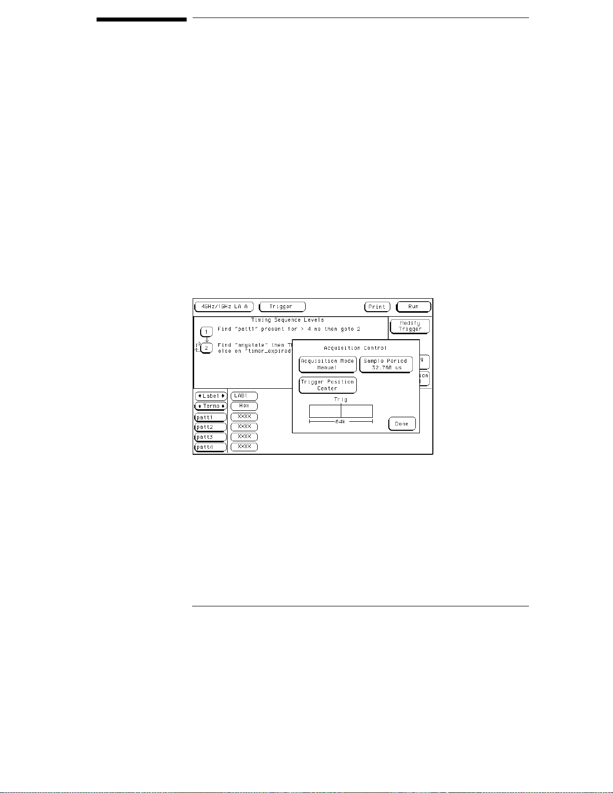
The Acquisition Control menu is used to set the acquisition mode, the
trigger position within available memory, and the sample period.
Acquisition Mode Field
The Acquisition Mode field toggles between Manual and Automatic. When
set to Automatic, the trigger position and sample period are computed based
on the sec/Div and delay settings in the Waveform menu.
When the Acquisition Mode field is set to Manual, additional configuration
fields become available. The additional configuration fields work together
with the sequence instructions, in a prioritized manner, to position the
memory in relation to the trigger point.
Acquisition Control Pop-up Menu (Timing Mode)
4–32
Page 73

The Trigger Menu
Trigger Position Field
Trigger Position Field
The Trigger Position field accesses a selection menu with the options of
Start, Center, End, User Defined, or Delay. When an option is selected, that
point of the available memory is positioned relative to the trigger. A
representation of this is shown by the blue graphic bar with the "Trig"
indicator line. The Trigger Position field determines how much data is stored
before and after the trigger occurs for all subsequent acquisitions.
When a Run is started, the analyzer will not look for a trigger until at least the
proper percent of pretrigger data has been stored. After a trigger has been
detected, the proper percent of posttrigger data is stored before the analyzer
halts.
Even when the trigger position is set to Start or End, there will always be a
small portion of pretrigger and posttrigger data stored.
Start
available memory is positioned relative to the trigger point. This results
in maximum posttrigger data and minimum pretrigger data.
Center
available memory is positioned relative to the trigger point. This results
in half pretrigger data and half posttrigger data.
End
memory is positioned relative to the trigger point. This results in
maximum pretrigger data and minimum posttrigger data.
User Defined
Store field appears. Use this field to set the trigger position any where
between 0% and 99%. As the Post Store is adjusted, the blue graphic bar
indicates the trigger position.
Delay
the trigger. The range of the delay time is affected by the sample period
but could range between 16 ns to 8 ks.
When the trigger position is set to Start, the starting point of
When the trigger position is set to Center, the center point of
When the trigger position is set to End, the end point of available
When the trigger position is set to User Defined, a Post
Use the Delay field to delay the start of acquisition storage after
4–33
Page 74
The Trigger Menu
Sample Period Field (Timing only)
Sample Period Field (Timing only)
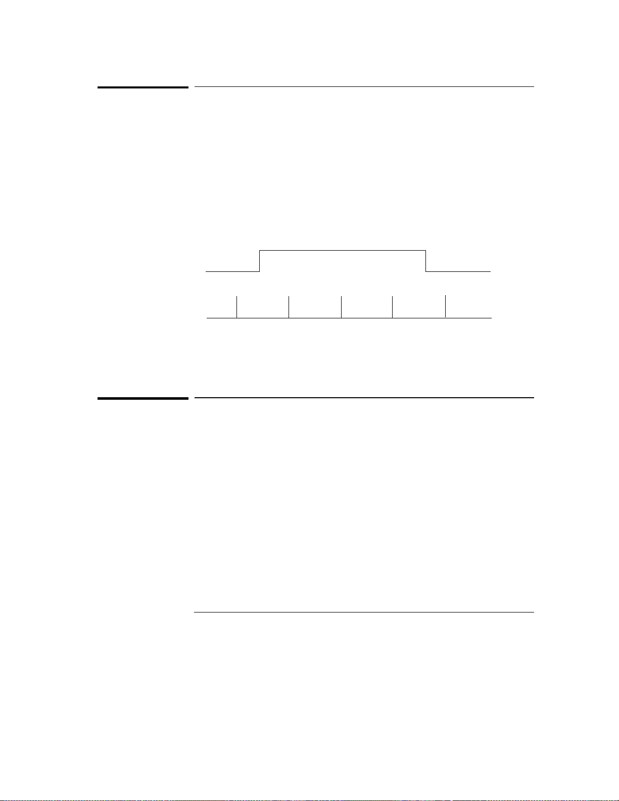
The Sample Period field is used to set the time period between data samples.
Every time a new sample is taken, the analyzer will see updated
measurement data.
In full-channel mode, the sample period is configurable. A list of choices
appear when the field is selected. In half-channel mode, the analyzer
automatically runs at a 250 ps sample period, and is not adjustable.
HHH
Measured Waveform
Sample Period
L
Sample 1 Sample 2
Sampling
Sample 3
Sample 4 Sample 5
L
Samples/Clock Field(State only)
The Samples/Clock field sets the number of extra sample points
(oversampling) between the external clock edges. All oversampled points
are evenly distributed within the period of the external clock. When the data
is displayed in the state listing, all sampled points are shown by default.
Oversampling is set in powers of two, up to a maximum of 32, or a sample
rate not exceeding 2 GSa/s. The equation below illustrates how the
maximum sample rate is limited.
(external clock rate) × (oversampled setting) ≤ 2 GHz
The external clock rate is checked at each run. If at any time the rate of
oversampling exceeds a 2 GHz rate, a lower Samples/Clock setting is
automatically chosen.
4–34
Page 75
The Trigger Menu
Samples/Clock Field(State only)
If at any time while configuring a measurement you notice some of the higher
oversampling rate choices not available, this means those choices would have
exceeded the 2 GHz sampling rate when multiplied by the external clock
rate. The interface will not make those choices available to you until the
external clock rate decreases.
See Also
Sample 1
Sample 1a
Oversample 1b
Oversample 1c
Oversample 1d
Sample 2
Sample 2a
Oversample 2b
Oversampling by a
factor of four
Oversample 2c
Oversample 2d
Sample 3
Sample 3a
Oversample 3b
Oversample 3c
Oversample 3d
Oversampling by 4
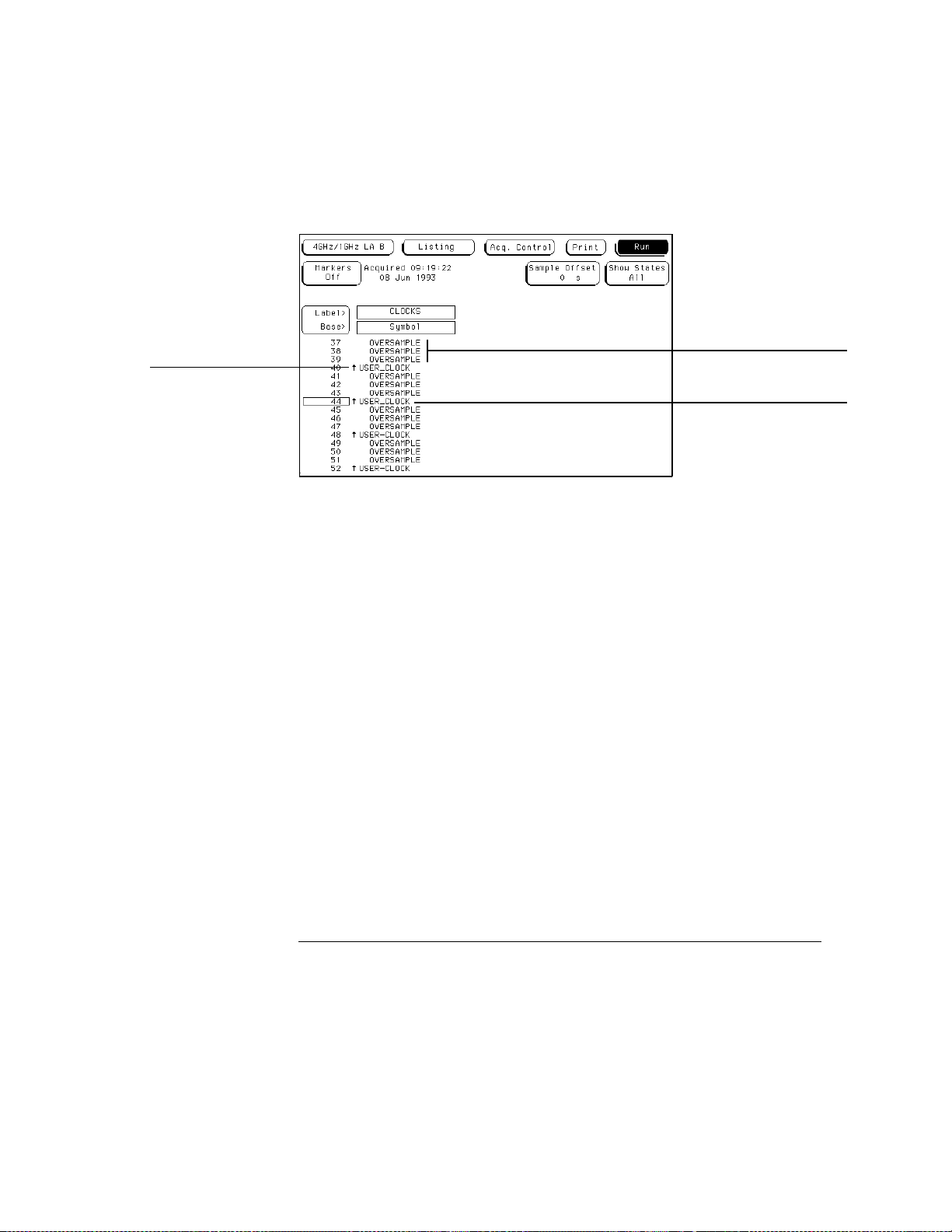
Once oversampling is set to a value greater than 1, arrows marking the
samples acquired at the specified clock edges appear in the Listing menu. In
the Waveform menu, the clocked states are marked with triangular tick
marks at the top of the waveform display.
"Show States Field" in the Listing menu chapter for more information on
displaying externally clocked states and oversampled states.
The analyzer will not trigger on points of oversampling.
The only points where the analyzer will trigger are the user’s external clock
transitions. If triggering is needed on these oversampled points, and the user
clock is less than 500 MHz, convert from state mode to timing mode where all
triggering is at 500 MHz.
4–35
Page 76
The Trigger Menu
Samples/Clock Field(State only)
The figure below shows data at the external clock transitions, data at the
points of oversampling, and the data points where the analyzer could trigger.
External clock transitions
are indicated by arrows
Oversampled points
Trigger points are
on external-clock
transitions only
Trigger Points
4–36
Page 77

Armed By Field
The logic analyzer can be armed by either the Run field, a Group Run through
the Intermodule Bus (IMB), or an external signal through an SMB Port
connector on the back panel.
Run/Group Run
Set the Armed By field to Run if you are using just a single analyzer to make a
measurement. When you select the Run/Stop field, you start the trigger
evaluation process immediately.
If the measurement includes other modules in the frame, and they are
configured as a Group Run in the Intermodule menu, the Run selection
becomes a Group Run selection. This type of configuration allows all
modules in the measurement to be time-correlated.
SMB Port
Set the Armed By field to the SMB Port option if you want to arm the
analyzer with an external arming signal from an outside source.
An arming signal can also come from another module within the frame, such
as an oscilloscope TRIG OUT signal. However, the only way the
measurement can be time-correlated is if both the sending and receiving
modules are configured as a Group Run in the system’s Intermodule menu.
Generally, the SMB Port is used when you want an external trigger source to
arm a module, or group of modules in the frame, or you want to take
advantage of the faster arming path.
See Also
"Intermodule Measurements" chapter in the
"Correlating Measurements" chapter in the
information on making a measurement using other modules through the IMB.
HP 16500B User’s Reference
HP 16500C User’s Reference
or
for
4–37
Page 78

4–38
Page 79
5
The Listing Menu
Page 80
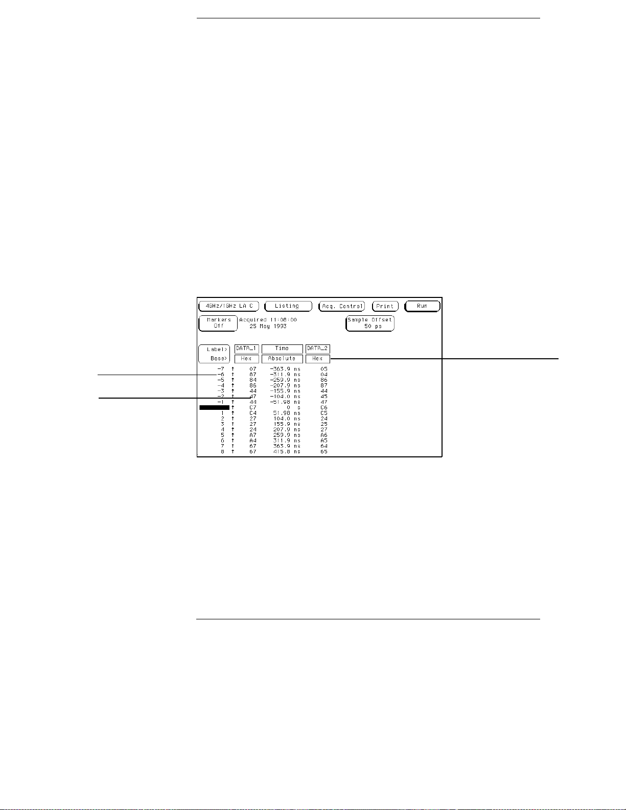
The Listing Menu
The Listing menu is a display menu for the acquired data in either the
state or timing acquisition modes. The acquired data is displayed in
the order the analyzer placed the data into memory. Data is grouped
and displayed by label and in a selectable base.
State listings display data, address, and control status at each clock
cycle of an external clock. Timing listings display signal activity
captured at selectable speeds of the analyzer’s internal clock.
Within the Listing menu, you also have the ability to mark data, and
control the amount of pretrigger and posttrigger data stored.
Memory locations
Data in memory
Base
The Listing Menu
5–2
Page 81
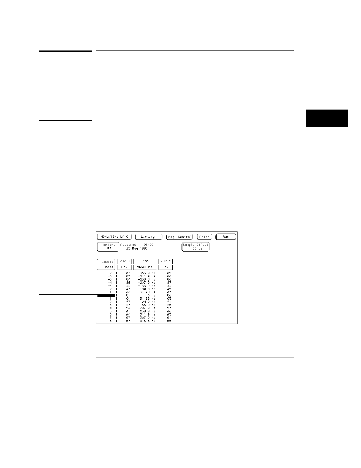
The Listing Menu
Markers Field
Markers Field
The Markers field may appear in different locations depending on the menu
you are in. Regardless of its location, the Markers field is always used to
access a marker selection menu.
See Also
"Markers and Stop Measurements" chapter found later in this reference for
complete information on marker and stop measurement operations.
Data Roll Field
The column of numbers at the far left represents the location of the acquired
data in the analyzer’s memory. The numbered positions are also known as
the state locations and are relative to the trigger state location.
The data can be rolled to display other data by using the data roll field. The
data roll field is the small rectangular box located in the middle of the state
location column.
The data roll field is used to either roll the data listing or to select an exact
state for display. When the data roll field is light blue, the knob is active and
can roll data in either direction. If you select the data roll field when it is
light blue, a pop-up keypad appears for the number of an exact state. When
the pop-up keypad is used, the data listing shifts, leaving the selected state in
the light blue data roll box.
Data roll field
Listing Menu with Data Roll Field
5–3
Page 82
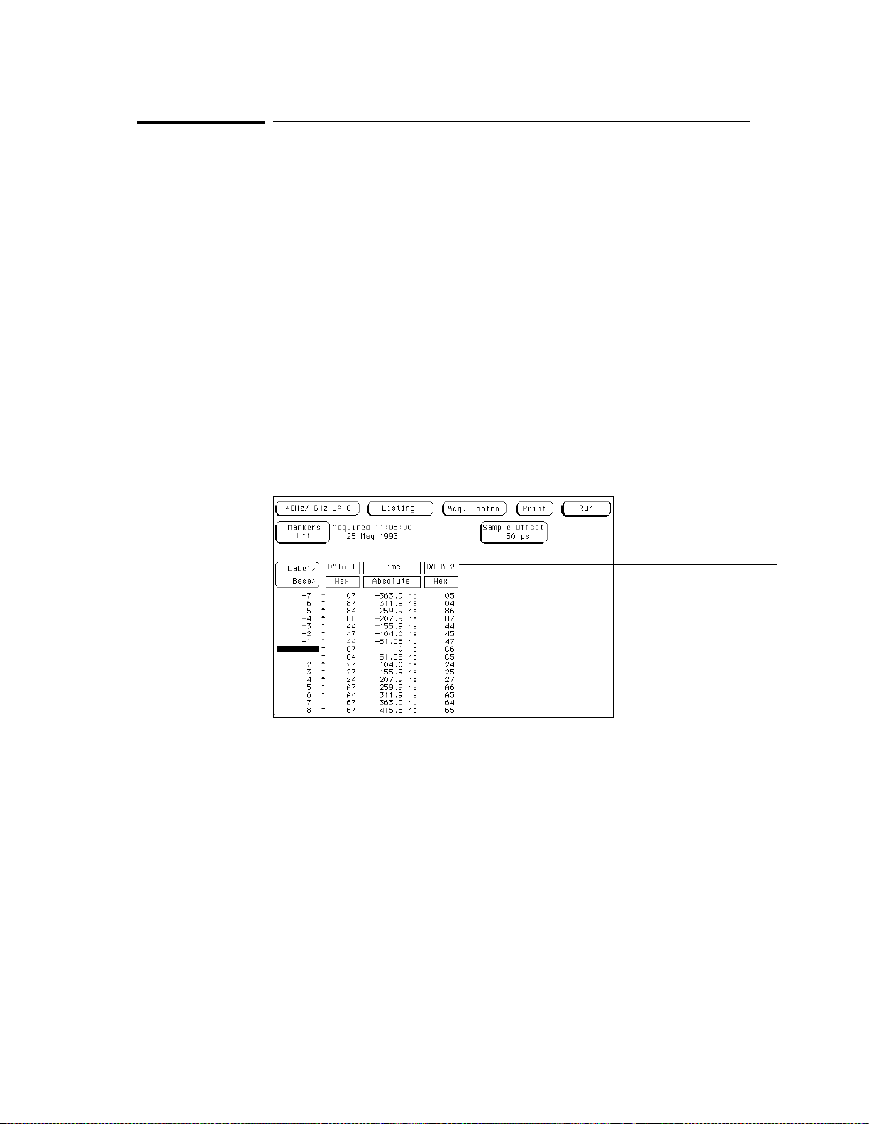
The Listing Menu
Label and Base Fields
Label and Base Fields
The Label and Base fields show up together in all menus except the Format
and Configuration menus. When a new label is assigned, a base field is
automatically assigned to that label.
Label Field
the Format menu. Labels assigned in the Format menu are displayed
throughout the analyzer as they were assigned in the Format menu. To
add, delete, or reorder the pre-assigned labels, select the label you want
to modify, then select the desired modify function. From the label
selection list that appears, choose the label you want to modify.
Base Field
changed in a menu, the base in other menus may not change accordingly.
For example, the base assigned to symbols is unique, as is the base
assigned in the Compare and Listing menus.
The base is changed by selecting the Base field under the desired label, then
selecting the new base from a selection menu. The base choices are Binary,
Octal, Decimal, Hex, ASCII, Symbol and Twos.
Labels in the Listing menu are the same labels assigned in
All labels have a base field assigned. If the numeric base is
Label field
Base field
Label and Base Fields
5–4
Page 83
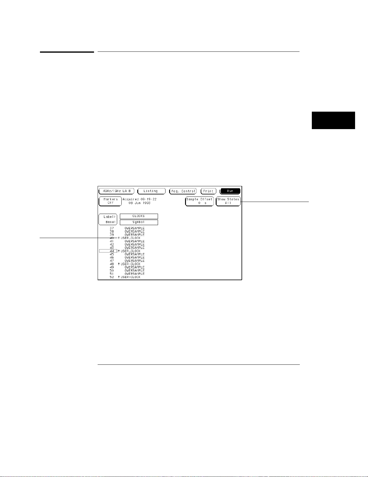
The Listing Menu
Show States All/Ext Clock (State only)
Show States All/Ext Clock (State only)
The Show States field only appears in the state acquisition mode and only
when an oversampling value is set. The field toggles between All and Ext Clk.
See Also
Arrow indicator for
external clock
"Samples/Clocks Field" in the Trigger menu for information about
oversampling.
All
The All selection displays both the externally clocked states and the
oversampled states. All externally clocked states are marked in the
Listing menu with arrows representing the specified clock edge. In the
Waveform menu, the clock states are marked with triangular tick marks
at the top of the waveform display.
Ext Clk
externally clocked states. Externally clocked states are those you would
have acquired without oversampling.
The Ext Clk (external clock) selection displays only the
Show states field
Show States Field
5–5
Page 84

The Listing Menu
Sample Offset Field (State only)
Sample Offset Field (State only)
The Sample Offset field only appears in the state acquisition mode, and
when the markers are turned off. Use it to offset the sample clock with
respect to the external clock edge. The Sample Offset field moves the
sample point closer to the start point of valid data.
See Also
See Also
See Also
"Set Sample Offset Field" in the Format Menu chapter.
Specify Patterns Field
The Specify Patterns field only appears when the Pattern markers are turned
on. For complete information on the function of the Specify Patterns field,
refer to "Specify Patterns Field" in the Markers and Stop Measurements
chapter found later in this reference.
"Specify Patterns Field" in the Markers and Stop Measurements chapter.
Acquisition Control Field
For complete information on the function of the Acquisition Control, refer to
"Acquisition Control" section in the Trigger menu.
5–6
Page 85

6
The Waveform Menu
Page 86
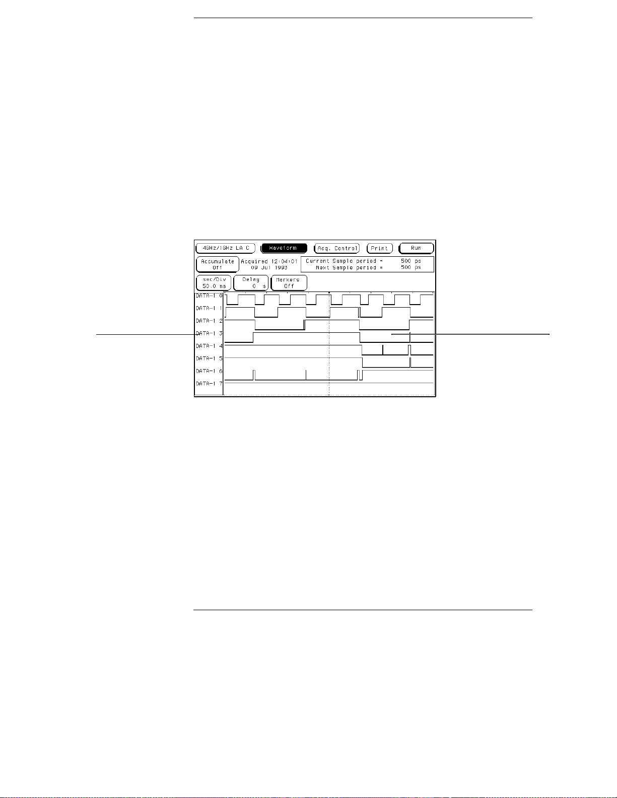
The Waveform Menu
The Waveform menu is one of the analyzer display menus. You use
the Waveform menu to view data captured in either state or timing
acquisition modes and in a format similar to an oscilloscope display.
Data is displayed with the horizontal axis representing time, and the
vertical axis representing logic highs and lows. The analyzer displays
the data in reference to the trigger point.
List of displayed
waveforms
Waveform display area
The Waveform Menu
6–2
Page 87
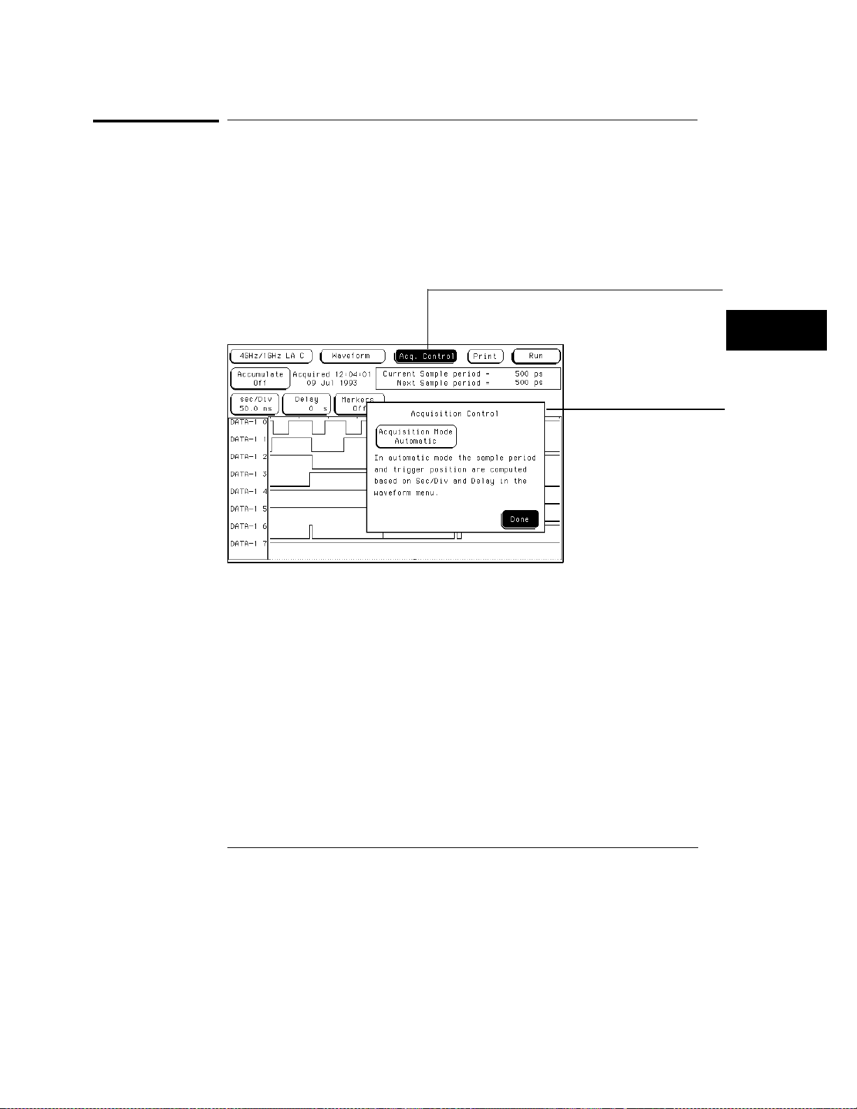
The Waveform Menu
Acquisition Control Field
Acquisition Control Field
The function of the Acquisition Control field in the Waveform menu is the
same as in the Trigger menu.
See Also
The "Acquisition Control Field" in the Trigger menu for complete details.
Acquisition control field
Acquisition control
menu
Acquisition Control Field
6–3
Page 88
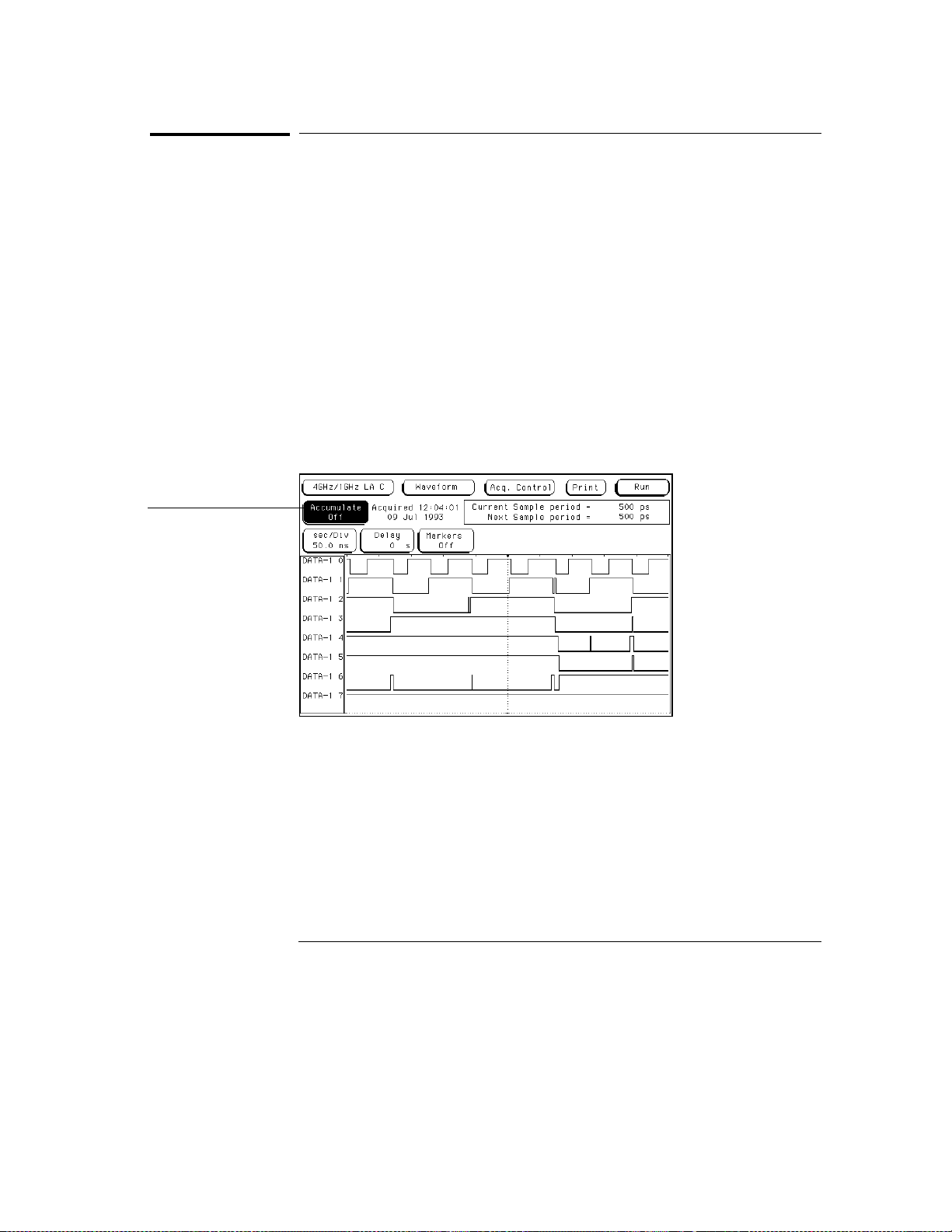
The Waveform Menu
Accumulate Field
Accumulate Field
The Accumulate field controls whether old data is cleared or displayed with
new data. The Accumulate field will toggle On/Off. When Accumulate is on,
the analyzer displays the data from a current acquisition on top of the
previously acquired data.
The time at which the old data is cleared depends on whether the analyzer is
run in Single or Repetitive mode. In Single mode, new data will be displayed
on top of the old each time the Run field is selected. In Repetitive mode,
data is cleared from the screen only when you start a run after stopping an
acquisition with the Stop field.
If you leave the Waveform menu, or pop up a menu over the waveform
display, any accumulated display data is lost and the accumulation process
starts over.
Accumulate field
Accumulate Field
6–4
Page 89
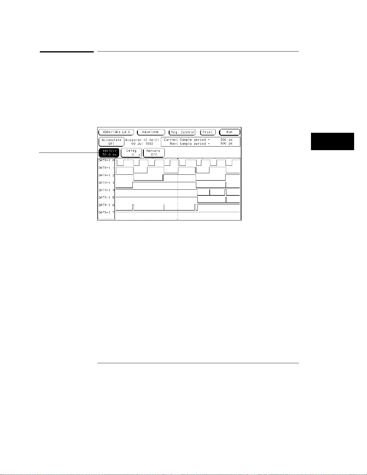
Seconds per division field
The Waveform Menu
Seconds Per Division Field
Seconds Per Division Field
Use the sec/Div field to select the seconds per division resolution. The range
of the sec/Div field is 250 ps/Div to 50 s/Div. You set the sec/Div field by
either selecting the sec/Div field and rotating the knob, or by selecting the
sec/Div field twice, and then using the pop-up keypad. When using the knob
to set the sec/Div, the value will change in a 1-2-5 sequence. By adjusting the
sec/Div, you can zoom in to view a desired part of the display.
Seconds Per Division Field
6–5
Page 90
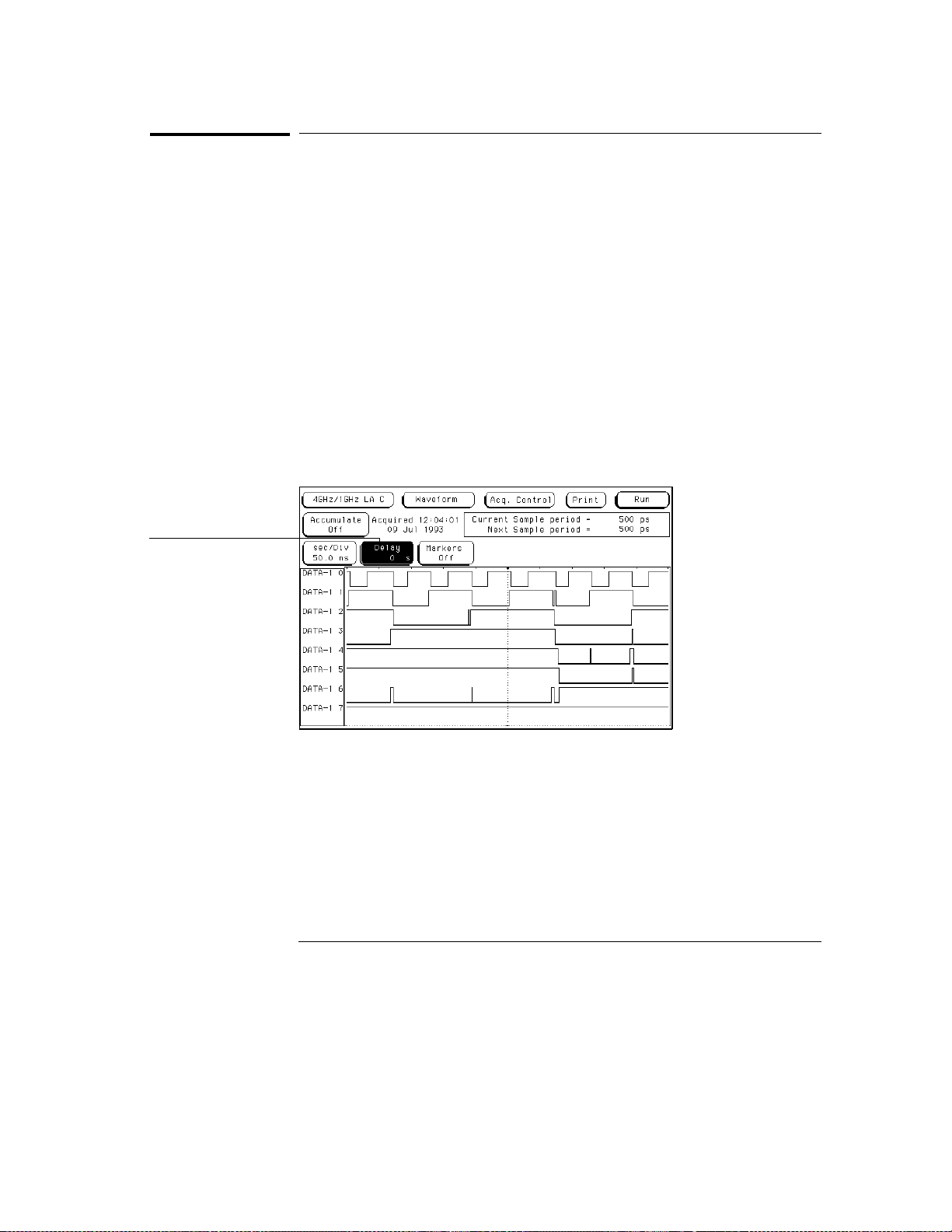
The Waveform Menu
Delay Field
Delay Field
The Delay field allows you to scroll the data and place the desired section at
center screen. Changing the delay will not effect the data acquisition unless
it is a timing analyzer and the acquisition mode is Automatic mode. The
delay range of a timing display is from −2500 seconds to + 2500 seconds.
If you want to move the display window to view data located offscreen to the
right, enter a positive delay. If you want to move the display window to view
data located offscreen to the left, enter a negative delay.
You can enter a delay using the knob by selecting the Delay field once, which
turns it light blue, then turning the knob. If you select the Delay field a
second time when it is light blue, a pop-up keypad appears, which enables
you to enter an exact number.
See Also
Delay field
The "Acquisition Control Field" in the Trigger menu for more information on
the effects of delay in the Automatic mode.
Delay Field
6–6
Page 91
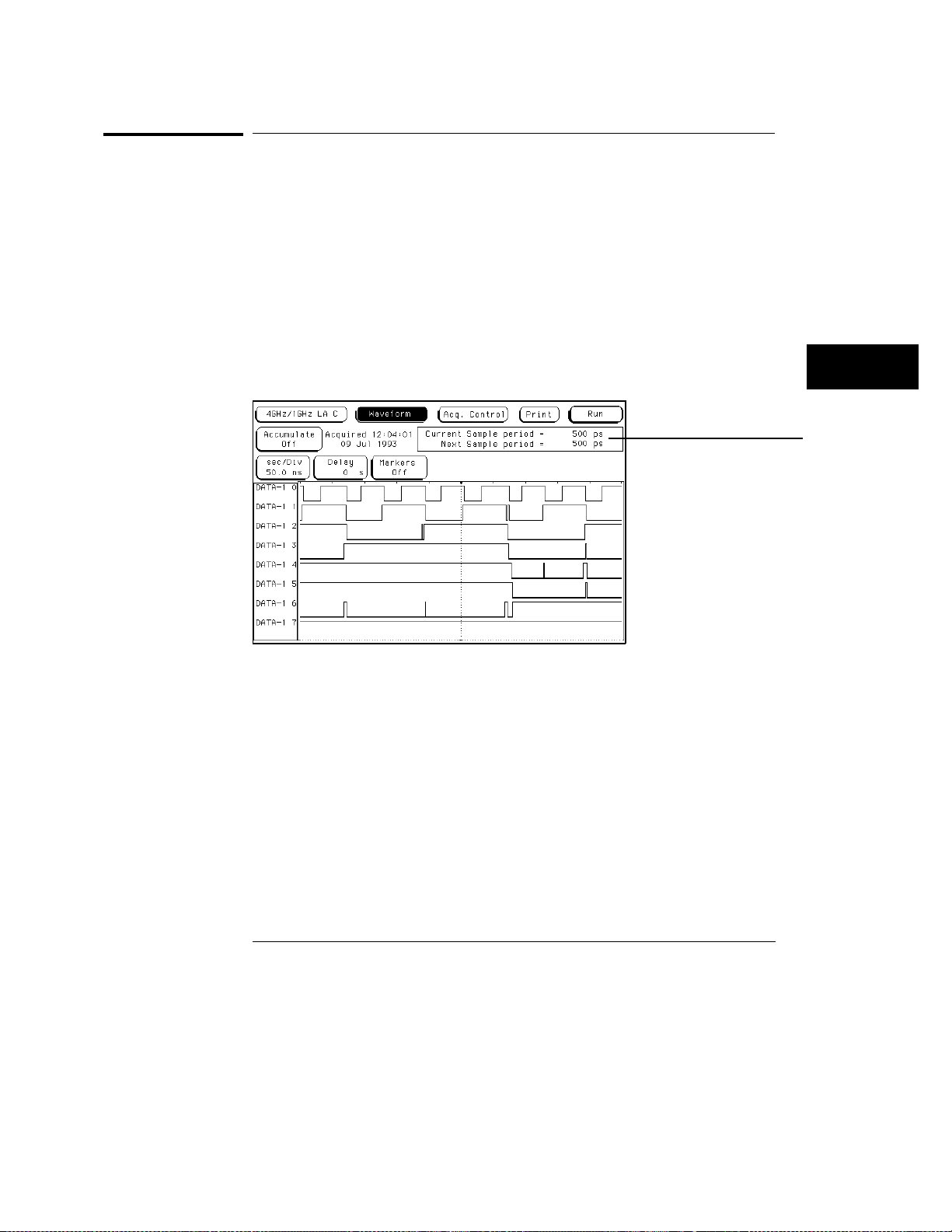
The Waveform Menu
Sample Period Display (Timing only) External Clock Period Display (State only)
Sample Period Display (Timing only)
External Clock Period Display (State only)
The Sample period display only appears in the timing acquisition mode. A
sample period is the interval of time between new data samples. Every time
a new acquisition is taken, the analyzer updates the measurement.
The Current Sample period display is the sample period used for the last
acquisition. The Next Sample period is the new sample period to be used at
the next acquisition. If the acquisition mode is set to automatic, changing the
sec/div or delay will affect the sample period.
Both of these display fields are hidden when markers are turned on.
Sample period display
Sample Period Display
Timing waveforms are reconstructed relevant to the sample period. The
shorter sample period puts more sample points on the waveform for a more
accurate reconstruction but also fills memory quicker.
If the sec/Div is changed resulting in a change in the next sample period, you
must run the analyzer again before the current sample period display is
updated.
6–7
Page 92
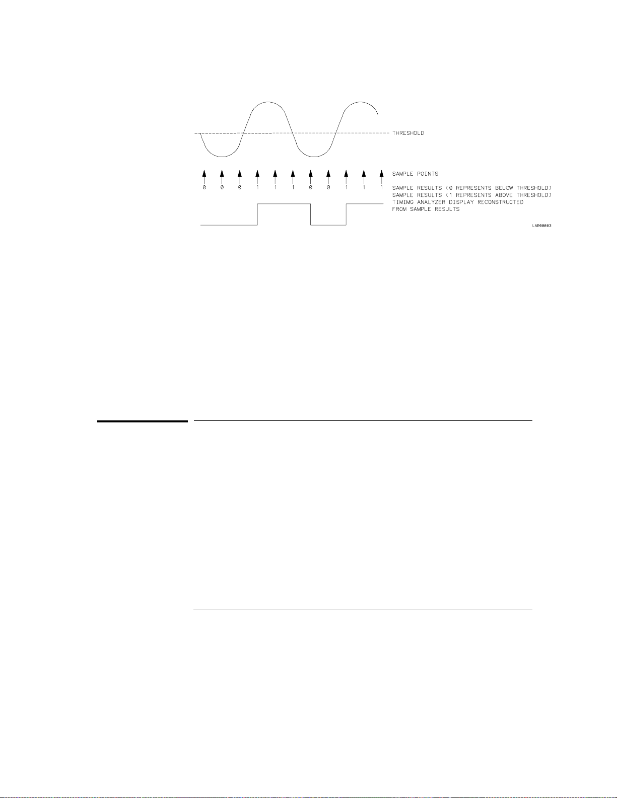
The Waveform Menu
Markers Field
Sample Points
The External Clock Period display only appears in the state acquisition mode.
The clock period display shows the speed of the clock from the target
system. Also displayed is the Samples/External Clock which shows how
many samples are taken per external clock cycle.
See Also
See Also
"Samples/Clock Field" in the Acquisition Control section of the Trigger menu
for more information on the use of the Samples/Clock field to set
oversampling in the state acquisition mode.
Markers Field
The Markers field may appear in different locations depending on the menu
you are in. Regardless of its location, the Markers field is always used to
access a marker selection menu.
"Markers and Stop Measurements" chapter found later in this reference for
complete information on marker and stop measurement operations.
6–8
Page 93

Waveform Display
The waveform display area of the Waveform menu shows state and
timing waveforms for labels assigned in the Format menu. It can also
combine and display waveforms from other measurement modules
when all modules are configured in a Group Run.
See Also
"Intermodule Measurements" chapter in the
System User’s Reference
Logic Analysis System User’s Reference
displays and Group Run.
or "Correlating Measurements" in the
HP 16500B Logic Analysis
HP 16500C
for more information on mixed
The waveform display area also accesses the fields used to select,
delete, or modify waveforms. The function of selecting waveforms for
display, and modifying or deleting waveforms is identical in both state
and timing acquisition modes.
Only analyzer waveforms which have bits assigned in the Format
menu can be displayed. Each waveform is a member of a set of
waveforms grouped under a label. The assigned label name in the
Format menu is the name that appears in the Labels selection list.
6–9
Page 94
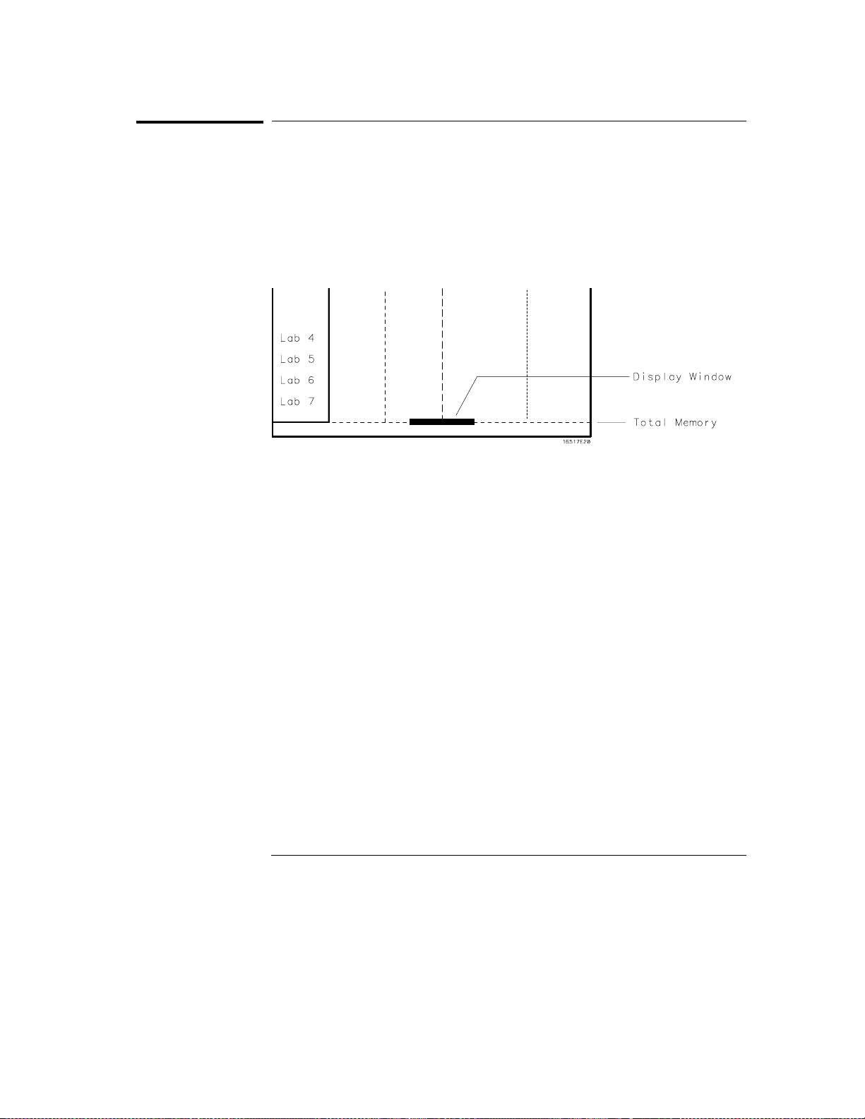
The Waveform Menu
Display Location Reference Line
Display Location Reference Line
At the bottom of the Waveform menu is a reference line that displays the
relative location of the display window with reference to the total memory.
Total memory is represented by a horizontal dotted line. The display window
is represented by the overlaid solid line.
Display Location Reference Line
6–10
Page 95
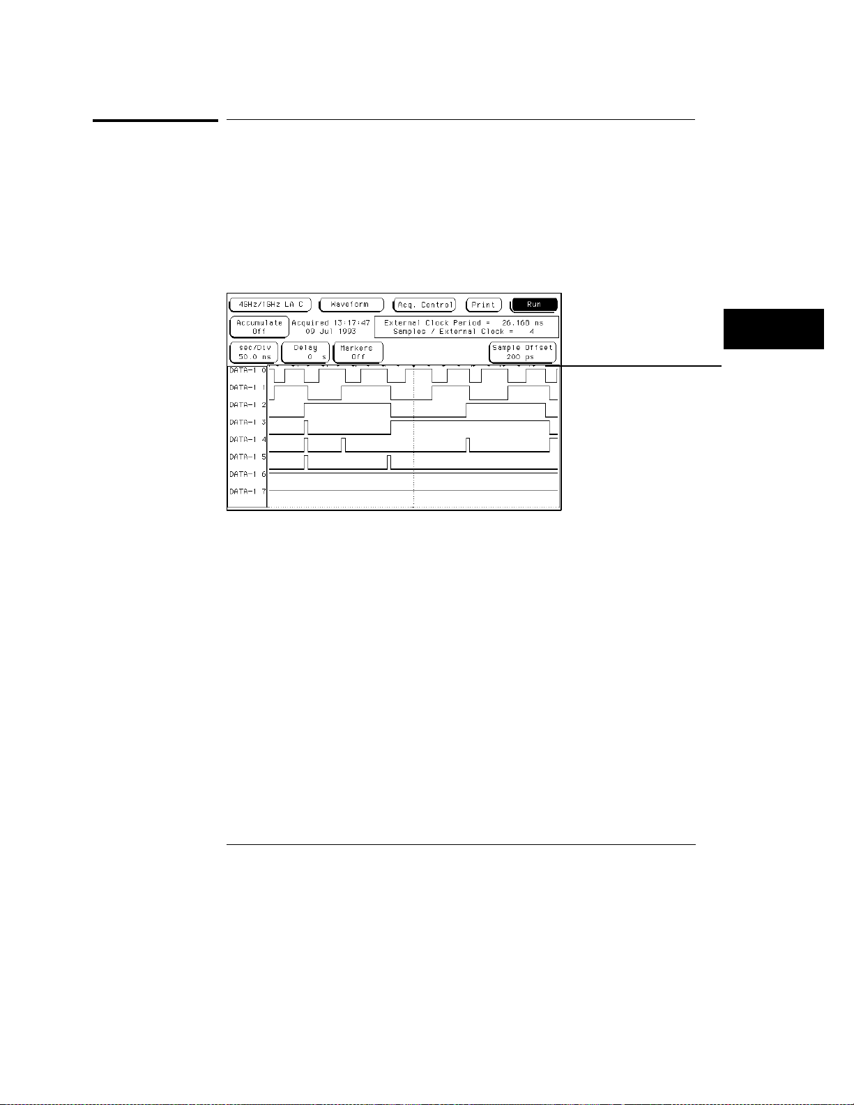
The Waveform Menu
External-Clock Indicators (State only)
External-Clock Indicators (State only)
When oversampling has an assigned value greater than 1, tick marks are
displayed at the top of the display showing where the external-clock
transitions occur in reference to the displayed waveforms.
See Also
"Samples/Clock Field" in the Trigger Menu chapter for information on
oversampling.
External-clock
indicators
External Clock Indicators
6–11
Page 96
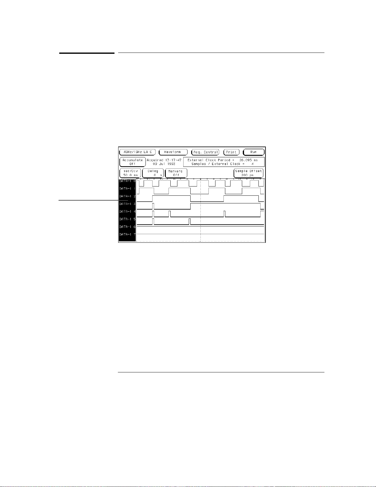
The Waveform Menu
Blue Bar Field
Blue Bar Field
The blue bar on the left side of the waveform display is both a display and
configuration field. After all desired waveforms are configured for display,
they are listed in the blue bar. If there are more waveforms than can be
displayed, the list is scrolled by selecting the dark blue bar. It then turns
light blue, and the knob is then used to scroll. If the blue bar is already light
blue, just turn the knob.
If the blue bar is selected when it is light blue, the Waveform Selection menu
appears. Use this menu to configure the waveform display.
Blue bar field
Blue Bar Field
6–12
Page 97
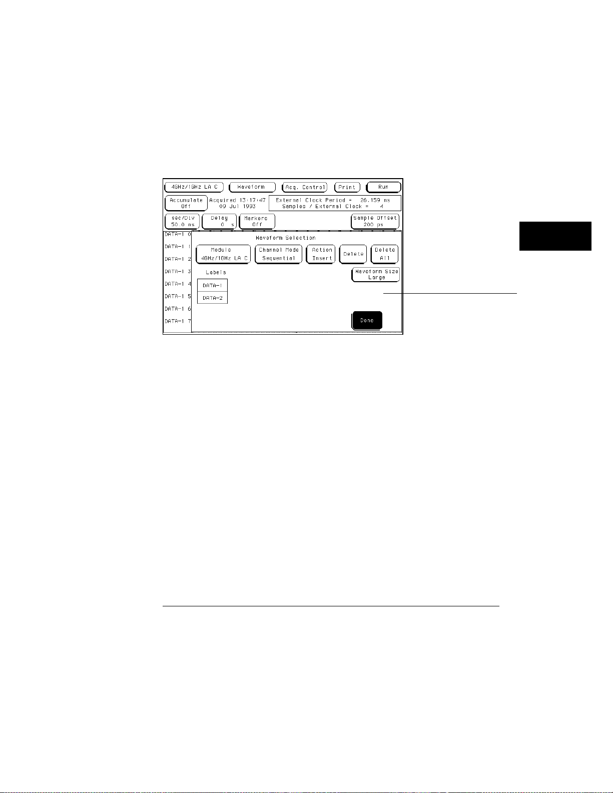
The Waveform Menu
Blue Bar Field
When the Waveform Selection pop-up menu appears, you select which
waveforms are displayed, replaced, or modified. You can display up to 24
waveforms on screen at one time.
Single waveforms or all waveforms under a label can be displayed or turned
off. How the waveform bits are assigned for display depends on what
Channel Mode is currently selected.
Waveform selection menu
Waveform Selection Menu
6–13
Page 98
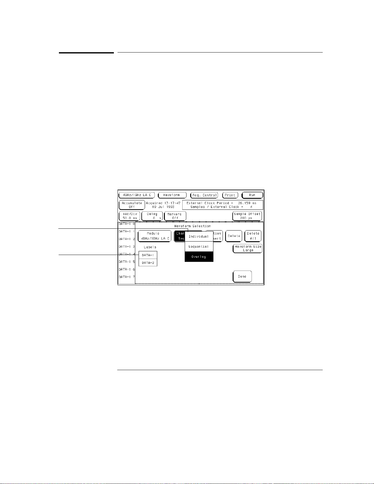
The Waveform Menu
Channel Mode Field
Channel Mode Field
The Channel Mode field selects which method is used to insert the waveform
labels into the display. All inserted labels are placed below the cursor in the
blue bar field. When the Channel Mode field is selected, a selection menu
appears with the choices below.
Sequential
The Sequential mode inserts all channels from the selected label, in order,
starting below the white cursor.
Individual
The Individual mode inserts selected channels from a label’s channel
selection list. The channel selection list appears when a label name is
selected. Channels are inserted starting below the white cursor.
Channel mode
selection pop-up
Label selection list
Channel Mode Selection Menu
6–14
Page 99
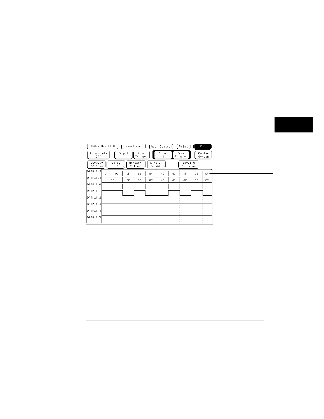
The Waveform Menu
Channel Mode Field
Overlay
The Overlay mode inserts all bits of a label in a single waveform to form a
composite waveform label. The onscreen indication for the Overlay mode is
"All" following the label name.
Viewing State Data in Overlay Mode
When all assigned waveforms in a label are overlaid, the value of the data is
displayed to the right of each new transition in the waveform display.
If the sec/Div is set to view a large increment of time, or if the waveform size
is set to Small or Medium, the state data readout will not fit between
transitions. To display the data readouts within the waveform, expand the
sec/Div and use the Large waveform setting. If symbols are assigned to
represent data values, the symbol is displayed.
Overlaid
waveforms
Data value or Symbol
displayed in waveform
State Data or Symbols In Overlaid Waveform
6–15
Page 100
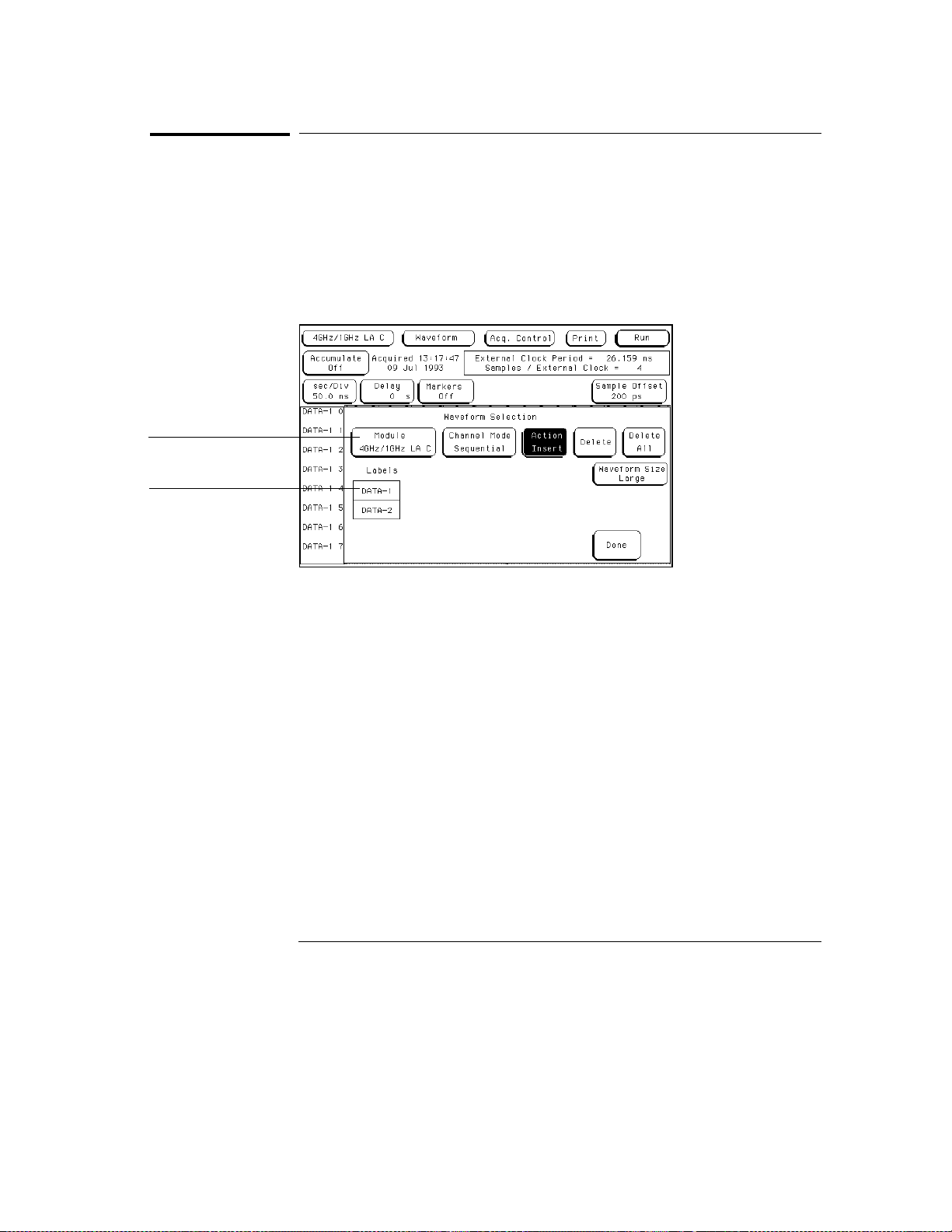
Module field
The Waveform Menu
Module and Label Fields
Module and Label Fields
If there are multiple analyzers or oscilloscope modules installed in the
mainframe, waveforms from the other modules can be displayed in the
waveform menu. The Module field accesses a selection list that contains the
modules installed in the mainframe, that are configured in a Group Run, and
have timing or oscilloscope waveforms.
Label fields
Module and Label Fields
6–16
 Loading...