

Page 1

User’s and Service Guide
Agilent Technologies 85050C
7 mm Precision Calibration Kit
This manual applies directly to 85050C calibration kits with serial number prefix 3106A.
The calibration devices in this kit are individually serialized. Record the device serial
numbers in the table provided in this manual (see “Recording the Device Serial Numbers”
in Chapter 1.)
Agilent Part Number: 85050-90051
Printed in USA
Print Date: August 2008
Supersedes: December 2006
© Copyright 1994, 1996, 2001, 2002, 2006, 2008 Agilent Technologies, Inc. All rights reserved.
Page 2

WARRANTY STATEMENT
THE MATERIAL CONTAINED IN THIS DOCUMENT IS PROVIDED “AS IS,” AND IS SUBJECT
TO BEING CHANGED, WITHOUT NOTICE, IN FUTURE EDITIONS. FURTHER, TO THE
MAXIMUM EXTENT PERMITTED BY APPLICABLE LAW, AGILENT DISCLAIMS ALL
WARRANTIES, EITHER EXPRESS OR IMPLIED WITH REGARD TO THIS MANUAL AND
ANY INFORMATION CONTAINED HEREIN, INCLUDING BUT NOT LIMITED TO THE
IMPLIED WARRANTIES OF MERCHANTABILITY AND FITNESS FOR A PARTICULAR
PURPOSE. AGILENT SHALL NOT BE LIABLE FOR ERRORS OR FOR INCIDENTAL
OR CONSEQUENTIAL DAMAGES IN CONNECTION WITH THE FURNISHING, USE, OR
PERFORMANCE OF THIS DOCUMENT OR ANY INFORMATION CONTAINED HEREIN.
SHOULD AGILENT AND THE USER HAVE A SEPARATE WRITTEN AGREEMENT WITH
WARRANTY TERMS COVERING THE MATERIAL IN THIS DOCUMENT THAT CONFLICT
WITH THESE TERMS, THE WARRANTY TERMS IN THE SEPARATE AGREEMENT WILL
CONTROL.
DFARS/Restricted Rights Notice
If software is for use in the performance of a U.S. Government prime contract or subcontract, Software is
delivered and licensed as “Commercial computer software” as defined in DFAR 252.227-7014 (June
1995), or as a “commercial item” as defined in FAR 2.101(a) or as “Restricted computer software” as
defined in FAR 52.227-19 (June 1987) or any equivalent agency regulation or contract clause. Use,
duplication or disclosure of Software is subject to Agilent Technologies’ standard commercial license
terms, and non-DOD Departments and Agencies of the U.S. Government will receive no greater than
Restricted Rights as defined in FAR 52.227-19(c)(1-2) (June 1987). U.S. Government users will receive
no greater than Limited Rights as defined in FAR 52.227-14 (June 1987) or DFAR 252.227-7015 (b)(2)
(November 1995), as applicable in any technical data.
Certification
Agilent Technologies, Inc. certifies that this product met its published specifications at the time of
shipment from the factory. Agilent Technologies, Inc. further certifies that its calibration measurements
are traceable to the United States National Institute of Standards and Technology, to the extent allowed
by the Institute's calibration facility, and to the calibration facilities of other International Standards
Organization members.
ii 85050C
Page 3

Assistance
Product maintenance agreements and other customer assistance agreements are available for Agilent
products.
For any assistance, contact Agilent Technologies. Refer to “Contacting Agilent” on page 4.
Printing Copies of Documentation from the Web
To print copies of documentation from the Web, download the PDF file from the Agilent web site:
•Go to www.agilent.com.
• Enter the document’s part number (located on the title page) in the Search box.
• Click Search.
• Click on the hyperlink for the document.
• Click the printer icon located in the tool bar.
85050C iii
Page 4

iv 85050C
Page 5

1. General Information
Calibration Kit Overview. . . . . . . . . . . . . . . . . . . . . . . . . . . . . . . . . . . . . . . . . . . . . . . . . . . . . . . . . . . . . . 1-2
Kit Contents . . . . . . . . . . . . . . . . . . . . . . . . . . . . . . . . . . . . . . . . . . . . . . . . . . . . . . . . . . . . . . . . . . . . . . 1-2
Calibration Definitions . . . . . . . . . . . . . . . . . . . . . . . . . . . . . . . . . . . . . . . . . . . . . . . . . . . . . . . . . . . . . . 1-3
Incoming Inspection. . . . . . . . . . . . . . . . . . . . . . . . . . . . . . . . . . . . . . . . . . . . . . . . . . . . . . . . . . . . . . . . . . 1-4
Serial Numbers . . . . . . . . . . . . . . . . . . . . . . . . . . . . . . . . . . . . . . . . . . . . . . . . . . . . . . . . . . . . . . . . . . . . . 1-4
Recording the Device Serial Numbers. . . . . . . . . . . . . . . . . . . . . . . . . . . . . . . . . . . . . . . . . . . . . . . . . . 1-4
Calibration Kits Documented in This Manual . . . . . . . . . . . . . . . . . . . . . . . . . . . . . . . . . . . . . . . . . . . . . 1-5
Calibration Kit History. . . . . . . . . . . . . . . . . . . . . . . . . . . . . . . . . . . . . . . . . . . . . . . . . . . . . . . . . . . . . . 1-5
85050C Kits with Serial Prefix 3027A. . . . . . . . . . . . . . . . . . . . . . . . . . . . . . . . . . . . . . . . . . . . . . . . . . 1-5
Preventive Maintenance . . . . . . . . . . . . . . . . . . . . . . . . . . . . . . . . . . . . . . . . . . . . . . . . . . . . . . . . . . . . . . 1-5
When to Calibrate . . . . . . . . . . . . . . . . . . . . . . . . . . . . . . . . . . . . . . . . . . . . . . . . . . . . . . . . . . . . . . . . . . . 1-6
2. Specifications
Environmental Requirements . . . . . . . . . . . . . . . . . . . . . . . . . . . . . . . . . . . . . . . . . . . . . . . . . . . . . . . . . . 2-2
Temperature—What to Watch Out For . . . . . . . . . . . . . . . . . . . . . . . . . . . . . . . . . . . . . . . . . . . . . . . . . 2-2
Mechanical Characteristics . . . . . . . . . . . . . . . . . . . . . . . . . . . . . . . . . . . . . . . . . . . . . . . . . . . . . . . . . . . . 2-3
Pin Depth . . . . . . . . . . . . . . . . . . . . . . . . . . . . . . . . . . . . . . . . . . . . . . . . . . . . . . . . . . . . . . . . . . . . . . . . 2-3
Precision Airline . . . . . . . . . . . . . . . . . . . . . . . . . . . . . . . . . . . . . . . . . . . . . . . . . . . . . . . . . . . . . . . . . . . 2-5
Electrical Specifications. . . . . . . . . . . . . . . . . . . . . . . . . . . . . . . . . . . . . . . . . . . . . . . . . . . . . . . . . . . . . . . 2-7
Certification . . . . . . . . . . . . . . . . . . . . . . . . . . . . . . . . . . . . . . . . . . . . . . . . . . . . . . . . . . . . . . . . . . . . . . 2-7
Contents
3. Use, Maintenance, and Care of the Devices
Electrostatic Discharge . . . . . . . . . . . . . . . . . . . . . . . . . . . . . . . . . . . . . . . . . . . . . . . . . . . . . . . . . . . . . . . 3-2
Visual Inspection . . . . . . . . . . . . . . . . . . . . . . . . . . . . . . . . . . . . . . . . . . . . . . . . . . . . . . . . . . . . . . . . . . . . 3-3
Look for Obvious Defects and Damage First. . . . . . . . . . . . . . . . . . . . . . . . . . . . . . . . . . . . . . . . . . . . . 3-3
Inspect the Mating Plane Surfaces . . . . . . . . . . . . . . . . . . . . . . . . . . . . . . . . . . . . . . . . . . . . . . . . . . . . 3-3
Cleaning Connectors . . . . . . . . . . . . . . . . . . . . . . . . . . . . . . . . . . . . . . . . . . . . . . . . . . . . . . . . . . . . . . . . . 3-4
Gaging Connectors . . . . . . . . . . . . . . . . . . . . . . . . . . . . . . . . . . . . . . . . . . . . . . . . . . . . . . . . . . . . . . . . . . . 3-6
Connector Gage Accuracy. . . . . . . . . . . . . . . . . . . . . . . . . . . . . . . . . . . . . . . . . . . . . . . . . . . . . . . . . . . . 3-6
When to Gage Connectors . . . . . . . . . . . . . . . . . . . . . . . . . . . . . . . . . . . . . . . . . . . . . . . . . . . . . . . . . . . 3-6
Reading the Connector Gage . . . . . . . . . . . . . . . . . . . . . . . . . . . . . . . . . . . . . . . . . . . . . . . . . . . . . . . . . 3-7
Gaging Procedure . . . . . . . . . . . . . . . . . . . . . . . . . . . . . . . . . . . . . . . . . . . . . . . . . . . . . . . . . . . . . . . . . . 3-8
Gaging the Airline . . . . . . . . . . . . . . . . . . . . . . . . . . . . . . . . . . . . . . . . . . . . . . . . . . . . . . . . . . . . . . . . 3-11
Connections . . . . . . . . . . . . . . . . . . . . . . . . . . . . . . . . . . . . . . . . . . . . . . . . . . . . . . . . . . . . . . . . . . . . . . . 3-13
How to Make a Connection. . . . . . . . . . . . . . . . . . . . . . . . . . . . . . . . . . . . . . . . . . . . . . . . . . . . . . . . . . 3-13
How to Separate a Connection . . . . . . . . . . . . . . . . . . . . . . . . . . . . . . . . . . . . . . . . . . . . . . . . . . . . . . . 3-15
Using the TRL Adapter . . . . . . . . . . . . . . . . . . . . . . . . . . . . . . . . . . . . . . . . . . . . . . . . . . . . . . . . . . . . 3-16
Pin/Collet Assemblies . . . . . . . . . . . . . . . . . . . . . . . . . . . . . . . . . . . . . . . . . . . . . . . . . . . . . . . . . . . . . . . 3-19
Using the Pin/Collet Assemblies . . . . . . . . . . . . . . . . . . . . . . . . . . . . . . . . . . . . . . . . . . . . . . . . . . . . . 3-19
Using the Centering Beads . . . . . . . . . . . . . . . . . . . . . . . . . . . . . . . . . . . . . . . . . . . . . . . . . . . . . . . . . 3-19
Handling and Storage . . . . . . . . . . . . . . . . . . . . . . . . . . . . . . . . . . . . . . . . . . . . . . . . . . . . . . . . . . . . . . . 3-20
4. Performance Verification
Introduction . . . . . . . . . . . . . . . . . . . . . . . . . . . . . . . . . . . . . . . . . . . . . . . . . . . . . . . . . . . . . . . . . . . . . . . . 4-2
How Agilent Verifies the Devices in Your Kit. . . . . . . . . . . . . . . . . . . . . . . . . . . . . . . . . . . . . . . . . . . . . . 4-2
v
Page 6

Contents
Recertification . . . . . . . . . . . . . . . . . . . . . . . . . . . . . . . . . . . . . . . . . . . . . . . . . . . . . . . . . . . . . . . . . . . . . . 4-3
How Often to Recertify . . . . . . . . . . . . . . . . . . . . . . . . . . . . . . . . . . . . . . . . . . . . . . . . . . . . . . . . . . . . . . 4-3
Where to Send a Kit for Recertification. . . . . . . . . . . . . . . . . . . . . . . . . . . . . . . . . . . . . . . . . . . . . . . . . 4-3
5. Troubleshooting
Troubleshooting Process . . . . . . . . . . . . . . . . . . . . . . . . . . . . . . . . . . . . . . . . . . . . . . . . . . . . . . . . . . . . . . 5-2
Where to Look for More Information . . . . . . . . . . . . . . . . . . . . . . . . . . . . . . . . . . . . . . . . . . . . . . . . . . . . 5-3
Returning a Kit or Device to Agilent . . . . . . . . . . . . . . . . . . . . . . . . . . . . . . . . . . . . . . . . . . . . . . . . . . . . 5-3
Contacting Agilent . . . . . . . . . . . . . . . . . . . . . . . . . . . . . . . . . . . . . . . . . . . . . . . . . . . . . . . . . . . . . . . . . . . 5-4
6. Replaceable Parts
Introduction . . . . . . . . . . . . . . . . . . . . . . . . . . . . . . . . . . . . . . . . . . . . . . . . . . . . . . . . . . . . . . . . . . . . . . . . 6-2
A. Standard Definitions
Class Assignments and Standard Definitions Values are Available on the Web . . . . . . . . . . . . . . . . . .A-2
vi
Page 7

1 General Information
85050C 1-1
Page 8

General Information
Calibration Kit Overview
Calibration Kit Overview
The Agilent 85050C 7 mm calibration kit is used to calibrate Agilent network analyzers up
to 18 GHz for measurements of components with 7 mm connectors.
The standards in this calibration kit allow you to perform 2-port TRL (thru-reflect-line)
calibrations.
This manual describes the 85050C calibration kit and provides replacement part numbers,
specifications, and procedures for using, maintaining, and troubleshooting the kit.
Kit Contents
The 85050C calibration kit includes the following items:
• calibration kit storage kit
• user’s and service guide
• offset open and shorts, broadband load, and lowband load termination
• 7 mm to 7 mm precision airline
• 7 mm to 7 mm TRL adapter
• screw-on gage 7 mm
• collet extractor tool
• center conductor collets
• pin-collet assembly
• 3/4 in, 135 N-cm (12 in-lb) torque wrench for use on the 7 mm connectors
• data disk that contains the calibration definitions of the devices in the kit for 8510
systems
• data disk set that contains the specifications and performance verification data for 8510
systems
Refer to Table 6-1 on page 6-2 and for a complete list of kit contents and their associated
part numbers.
NOTE
A backup copy of each data disk and printout should be made immediately
upon receipt of the calibration kit. Refer to your analyzer user’s guide for
instructions on duplicating a disk.
To view an online VNA user guide, use the following steps:
1. Go to www.agilent.com.
2. Enter your VNA model number (Ex: 8720ES) in the Search box and
click Search.
3. Click on Manuals.
4. Click on the title/hyperlink for the User Guide PDF you want to view. If
the User Guide you want to view isn’t listed on the Web page that is
seen initially, click on the More hyperlink (if displayed).
1-2 85050C
Page 9

General Information
Calibration Kit Overview
Offset Opens and Shorts
The offset opens and shorts are built from parts that are machined to the current
state-of-the-art in precision machining.
The offset short’s inner conductors have a one-piece construction, common with the
shorting plane. The construction provides for extremely repeatable connections.
The offset opens have inner conductors that are supported by a strong, low-dielectric
constant plastic to minimize compensation values.
Both the opens and shorts are constructed so that the pin depth can be controlled very
tightly, thereby minimizing phase errors. The lengths of the offsets in the opens and shorts
are designed so that the difference in phase of their reflection coefficients is approximately
180 degrees at all frequencies.
Broadband Load
The broadband load is a metrology-grade termination that has been optimized for
performance up to 18 GHz. The rugged internal structure provides for highly repeatable
connections. A distributed resistive element on sapphire provides excellent stability and
return loss. The broadband load is a valid substitute for a lowband load.
Precision Airline
The precision airline is a metrology-grade impedance reference device. The characteristic
impedance (Z
) of the line establishes the reference impedance after error correction is
0
applied.
Calibration Definitions
The calibration kit must be selected and the calibration definitions for the devices in the
kit installed in the network analyzer prior to performing a calibration. Refer to your
network analyzer user’s guide for instructions on selecting the calibration kit and
performing a calibration.
The calibration definitions can be:
• resident within the analyzer
• loaded from the provided disk
• entered from the front panel
Installation of the Calibration Definitions
The calibration definitions for the kit may be permanently installed in the internal
memory or hard disk of the network analyzer.
If the calibration definitions for the kit are not permanently installed in the network
analyzer, they must be manually entered. Refer to your network analyzer user’s guide for
instructions.
Equipment Required but Not Supplied
Connector cleaning supplies and various electrostatic discharge (ESD) protection devices
85050C 1-3
Page 10

General Information
Incoming Inspection
are not supplied with the calibration kit but are required to ensure successful operation of
the kit. Refer to Table 6-2 on page 6-3 for ordering information.
Incoming Inspection
Refer to “Kit Contents” on page 1-2 to verify a complete shipment. Use Table 1-1 to record
the serial numbers of all serialized devices in your kit.
Check for damage. The foam-lined storage case provides protection during shipping. If the
case or any device appears damaged, or if the shipment is incomplete, refer to “Contacting
Agilent” on page 5-4. Agilent will arrange for repair or replacement of incomplete or
damaged shipments without waiting for a settlement from the transportation company.
See “Returning a Kit or Device to Agilent” on page 5-3.
Serial Numbers
A serial number is attached to this calibration kit. The first four digits followed by a letter
comprise the serial number prefix; the last five digits are the suffix, unique to each
calibration kit.
Recording the Device Serial Numbers
In addition to the kit serial number, the devices in the kit are individually serialized (serial
numbers are labeled onto the body of each device). Record these serial numbers in
Table 1-1. Recording the serial numbers will prevent confusing the devices in this kit with
similar devices from other kits.
Table 1-1 Serial Number Record for the 85050C
Device Serial Number
Calibration kit
7 mm Precision Airline
Lowband load
Broadband load
Open
Short (collet style)
_______________________________
_______________________________
_______________________________
_______________________________
_______________________________
_______________________________
Short (threaded center conductor style)
TRL adapter
Connector Gage
Gage Master
1-4 85050C
_______________________________
_______________________________
_______________________________
_______________________________
Page 11

General Information
Calibration Kits Documented in This Manual
Calibration Kits Documented in This Manual
This manual applies to any 85050C calibration kit whose serial number is listed on the
title page. If your calibration kit has a different serial number prefix, refer to the
“Calibration Kit History” section below for information on how this manual applies.
Calibration Kit History
This section describes calibration kits with serial number prefixes lower that the ones
listed on the title page.
85050C Kits with Serial Prefix 3027A
These calibration kits did not have the calibration definitions disk to support the Agilent
8510C network analyzer. The part numbers provided in this manual are the recommended
replacement parts for these kits. The devices in these kits should meet the specifications
published in this manual.
Preventive Maintenance
The best techniques for maintaining the integrity of the devices in the kit include:
• routine visual inspection
• cleaning
• proper gaging
• proper connection techniques
All of these are described in Chapter 3 , “Use, Maintenance, and Care of the Devices.”
Failure to detect and remove dirt or metallic particles on a mating plane surface can
degrade repeatability and accuracy and can damage any connector mated to it. Improper
connections, resulting from pin depth values being out of the observed limits (see Table 2-2
on page 2-5) or from bad connection techniques, can also damage these devices.
85050C 1-5
Page 12

General Information
When to Calibrate
When to Calibrate
A network analyzer calibration remains valid as long as the changes in the systematic
error are insignificant. This means that changes to the uncorrected leakages (directivity
and isolation), mismatches (source match and load match), and frequency response of the
system are small (<10%) relative to accuracy specifications.
Change in the environment (especially temperature) between calibration and
measurement is the major cause in calibration accuracy degradation. The major effect is a
change in the physical length of external and internal cables. Other important causes are
dirty and damaged test port connectors and calibration standards. If the connectors
become dirty or damaged, measurement repeatability and accuracy is affected.
Fortunately, it is relatively easy to evaluate the general validity of the calibration. To test
repeatability, remeasure one of the calibration standards. If you can not obtain repeatable
measurements from your calibration standards, maintenance needs to be performed on the
test port connectors, cables and calibration standards. Also, maintain at least one sample
of the device under test or some known device as your reference device. A verification kit
may be used for this purpose. After calibration, measure the reference device and note its
responses. Periodically remeasure the device and note any changes in its corrected
response which can be attributed to the test system. With experience you will be able to see
changes in the reference responses that indicate a need to perform the measurement
calibration again.
1-6 85050C
Page 13

2 Specifications
85050C 2-1
Page 14

Specifications
Environmental Requirements
Environmental Requirements
Table 2-1 Environmental Requirements
Parameter Limits
Temp er at ur e
Operating
Storage −40 °C to +75 °C
Error-corrected range
Relative humidity Type tested, 0% to 95% at 40 °C, non-condensing
a. The temperature range over which the calibration standards maintain conformance to their
b. The allowable network analyzer ambient temperature drift during measurement calibration
a
b
specifications.
and during measurements when the network analyzer error correction is turned on. Also, the
range over which the network analyzer maintains its specified performance while correction
is turned on.
+20 °C to +26 °C
± 1 °C of measurement calibration temperature
Temperature—What to Watch Out For
Changes in temperature can affect electrical characteristics. Therefore, the operating
temperature is a critical factor in performance. During a measurement calibration, the
temperature of the calibration devices must be stable and within the range shown in
Table 2-1.
IMPORTANT
Avoid unnecessary handling of the devices during calibration because your
fingers are a heat source.
2-2 85050C
Page 15

Specifications
Mechanical Characteristics
Mechanical Characteristics
Mechanical characteristics such as center conductor protrusion and pin depth are not
performance specifications. They are, however, important supplemental characteristics
related to electrical performance. Agilent Technologies verifies the mechanical
characteristics of the devices in the kit with special gaging processes and electrical testing.
This ensures that the device connectors do not exhibit any center conductor protrusion or
improper pin depth when the kit leaves the factory.
“Gaging Connectors” on page 3-6 explains how to use gages to determine if the kit devices
have maintained their mechanical integrity. Refer to Table 2-2 on page 2-5 for typical and
observed pin depth limits.
Pin Depth
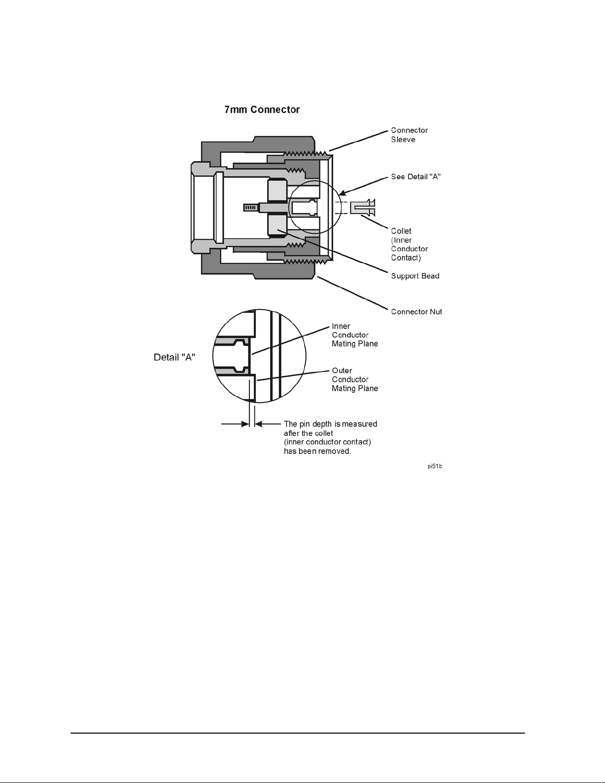
Pin depth is the distance the center conductor mating plane differs from being flush with
the outer conductor mating plane. See Figure 2-1. The pin depth of a connector can be in
one of two states: either protruding or recessed.
Protrusion is the condition in which the center conductor extends beyond the outer
conductor mating plane. This condition will indicate a positive value on the connector gage.
Recession is the condition in which the center conductor is set back from the outer
conductor mating plane. This condition will indicate a negative value on the connector
gage.
85050C 2-3
Page 16
Specifications
Mechanical Characteristics
Figure 2-1 Connector Pin Depth
The pin depth value of each calibration device in the kit is not specified, but is an
important mechanical parameter. The electrical performance of the device depends, to
some extent, on its pin depth. The electrical specifications for each device in the kit take
into account the effect of pin depth on the device’s performance. Table 2-2 lists the typical
pin depths and measurement uncertainties, and provides observed pin depth limits for the
devices in the kit. If the pin depth of a device does not measure within the observed pin
depth limits, it may be an indication that the device fails to meet electrical specifications.
Refer to Figure 2-1 for a visual representation of proper pin depth (slightly recessed).
2-4 85050C
Page 17

Table 2-2 Pin Depth Limits
Specifications
Mechanical Characteristics
Device
Typical Pin Depth
micrometers
–4
(10
inches)
Opens 0 to −12.7
(0 to −5.0)
Shorts +25.4 to −25.4
(+1.0 to −1.0)
Lowband loads 0 to −50.8
(0 to −20.0)
Broadband
loads
TRL adapter
(test port end)
TRL adapter
(airline end)
a. Approximately +2 sigma to −2 sigma of gage uncertainty based on studies done at the factory
according to recommended procedures.
b. Observed pin depth limits are the range of observation limits seen on the gage reading due to
measurement uncertainty. The depth could still be within specifications.
0 to −7.62
(0 to −3.0)
0 to −50.8
(0 to −20.0)
0 to −5.1
(0 to −2.0)
Measurement Uncertainty
micrometers
–4
(10
inches)
+10.20 to −10.20
(+ 4.0 to −4.0)
+6.4 to −6.4
(+ 2.5 to −2.5)
+4.1 to −4.1
(+ 1.6 to −1.6)
+4.1 to −4.1
(+ 1.6 to −1.6)
+4.1 to −4.1
(+ 1.6 to −1.6)
+4.1 to −4.1
(+ 1.6 to −1.6)
a
Observed Pin Depth Limits
micrometers
–4
(10
inches)
+10.20 to −22.90
(+ 4.0 to −9.0)
+31.8 to −31.8
(+ 3.5 to −3.5)
+4.1 to −54.9
(+ 1.6 to −21.6)
+4.1 to −11.7
(+ 1.6 to −4.6)
+4.1 to −54.9
(+ 1.6 to −21.6)
+4.1 to −9.1
(+ 1.6 to −3.6)
b
NOTE
When measuring pin depth, the measured value (resultant average of three
or more measurements) is not the true value. Always compare the measured
value with the observed pin depth limits in Table 2-2 to evaluate the
condition of device connectors.
Precision Airline
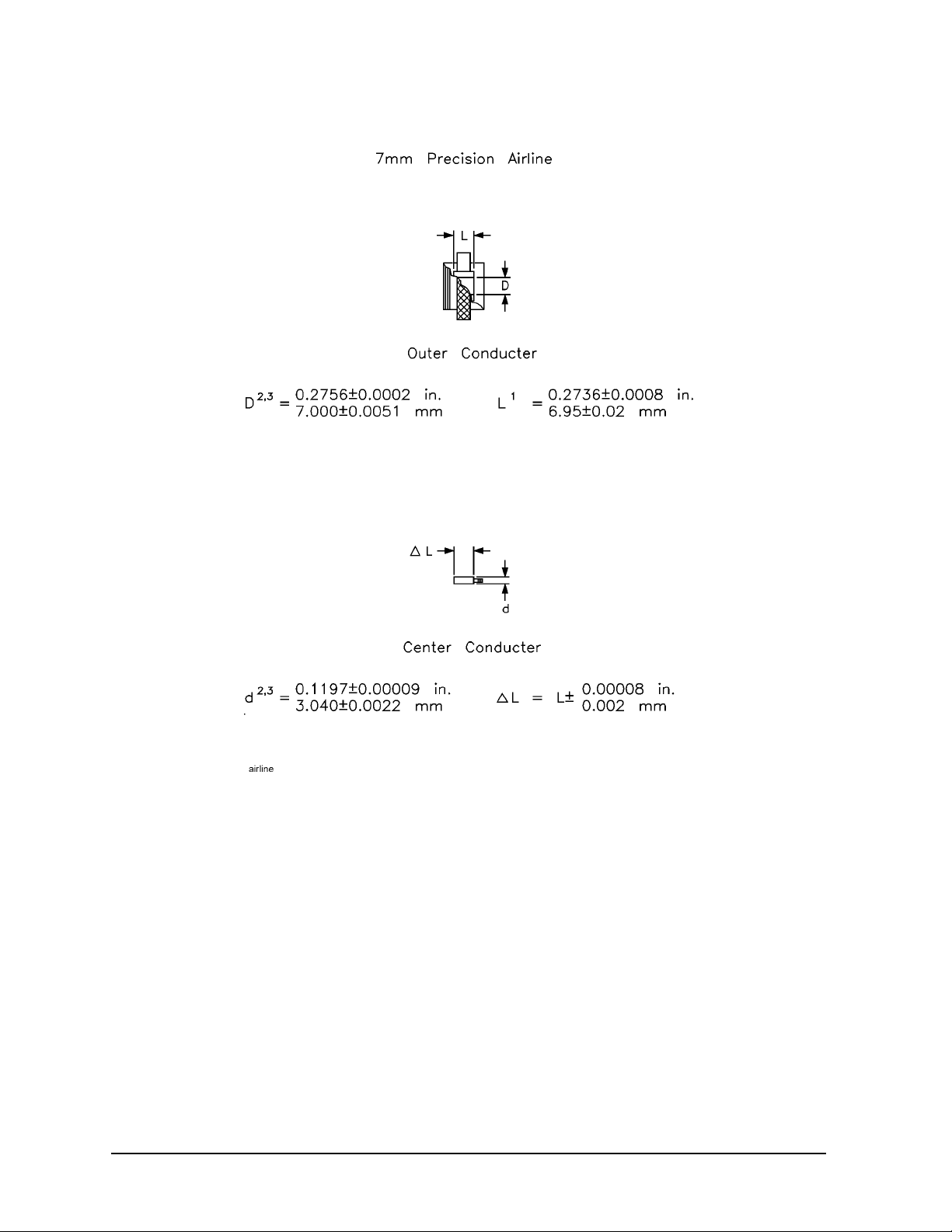
• The actual length of the calibration airline is on a label installed in a recess within the
knurled portion of the outer conductor.
• Diameters “D” and “d” are matched in the factory to assure a return loss
intermix the center and outer conductors between calibration kits.
• Measurement by the user of the diameters is not recommended, and will cause damage
to the calibration airline, due to the lack of proper measuring equipment and tooling.
≥ 60 dB. Do not
85050C 2-5
Page 18
Specifications
Mechanical Characteristics
Figure 2-2 7 mm Airline Mechanical Dimensions
2-6 85050C
Page 19

Specifications
Electrical Specifications
Electrical Specifications
The electrical specifications in Table 2-3 apply to the devices in your calibration kit when
connected with an Agilent precision interface.
Table 2-3 Electrical Specifications for 85050C 7 mm Devices
Device Specification Frequency (GHz)
Lowband load
Broadband load ≥ 38 dΒ Return loss dc to 18 GHz
b
(collet style)
Short
Shortb (threaded center
conductor style)
b
Open
Precision Airline
a. This lowband fixed load is not used or specified at frequencies greater than 2 GHz in
this kit. The same device having the same part number may be used elsewhere in
another kit, or by itself and have the following characteristics:
≥ 52 dB Return loss, dc to 5 GHz (specified)
≥ 46 dB Return loss, 5 GHz to 6 GHz (specified)
≥ 23 dB Return loss, 6 GHz to 18 GHz (typical)
b. The specifications for the opens and shorts are given as allowed deviation from the
nominal model as defined in the standard definitions.
c. Nominal, in this case, means the electrical characteristics as defined by the calibration
definitions supplied on the calibration definitions disk.
d. This specification is based on mechanical measurements. Refer to the Certificate of
Calibration that came with your kit for the exact dimensions of your airline.
≥ 52 dΒ Return loss
± 0.2° from nominal
± 0.3° from nominal
± 0.5° from nominal
± 0.2° from nominal
± 0.3° from nominal
± 0.5° from nominal
± 0.3° from nominal
± 0.4° from nominal
± 0.6° from nominal
≥ 60 dΒ Return loss
dc to 2 GHz
dc to 2 GHz
2 to 8 GHz
8 to 18 GHz
dc to 2 GHz
2 to 8 GHz
8 to 18 GHz
dc to 2 GHz
c
c
2 to 18 GHz
8 to 18 GHz
2 to 18 GHz
a
c
c
c
c
c
c
c
d
Certification
Agilent Technologies certifies that this product met its published specifications at the time
of shipment from the factory. Agilent further certifies that its calibration measurements
are traceable to the United States National Institute of Standards and Technology (NIST)
to the extent allowed by the institute’s calibration facility, and to the calibration facilities
of other International Standards Organization members. See “How Agilent Verifies the
Devices in Your Kit” on page 4-2 for more information.
85050C 2-7
Page 20

Specifications
Electrical Specifications
2-8 85050C
Page 21

3 Use, Maintenance, and Care of the
Devices
85050C 3-1
Page 22
Use, Maintenance, and Care of the Devices
Electrostatic Discharge
Electrostatic Discharge
Protection against electrostatic discharge (ESD) is essential while connecting, inspecting,
or cleaning connectors attached to a static-sensitive circuit (such as those found in test
sets).
Static electricity can build up on your body and can easily damage sensitive internal
circuit elements when discharged. Static discharges too small to be felt can cause
permanent damage. Devices such as calibration components and devices under test (DUT),
can also carry an electrostatic charge. To prevent damage to the test set, components, and
devices:
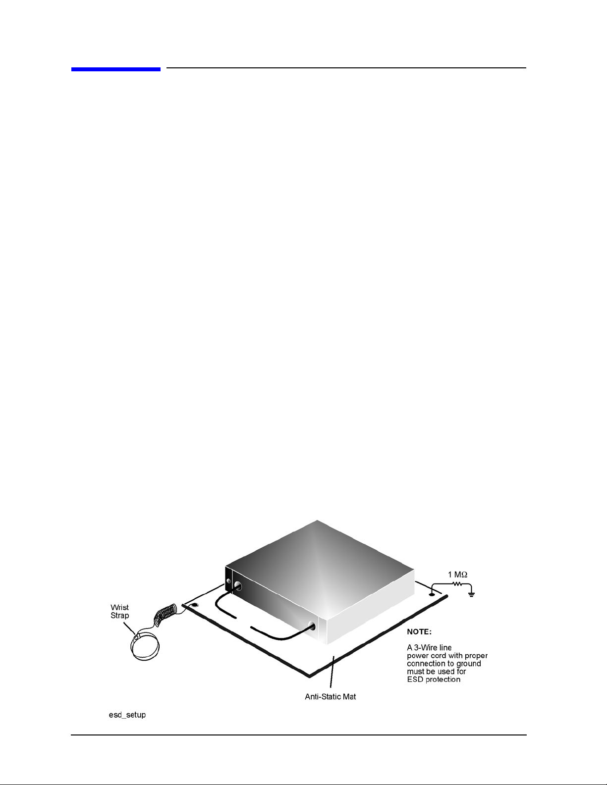
• Always wear a grounded wrist strap having a 1 MΩ resistor in series with it when
handling components and devices or when making connections to the test set.
• Always use a grounded antistatic mat in front of your test equipment.
• Always wear a heel strap when working in an area with a conductive floor. If you are
uncertain about the conductivity of your floor, wear a heel strap.
• Always ground yourself before you clean, inspect, or make a connection to a
static-sensitive device or test port. You can, for example, grasp the grounded outer shell
of the test port or cable connector briefly.
• Always ground the center conductor of a test cable before making a connection to the
analyzer test port or other static-sensitive device. This can be done as follows:
1. Connect a short (from your calibration kit) to one end of the cable to short the center
conductor to the outer conductor.
2. While wearing a grounded wrist strap, grasp the outer shell of the cable connector.
3. Connect the other end of the cable to the test port.
4. Remove the short from the cable.
Figure 3-1 shows a typical ESD protection setup using a grounded mat and wrist strap.
Refer to Chapter 6, “Replaceable Parts,” for information on ordering supplies for ESD
protection.
Figure 3-1 ESD Protection Setup
3-2 85050C
Page 23

Use, Maintenance, and Care of the Devices
Visual Inspection
Visual Inspection
Visual inspection and, if necessary, cleaning should be done every time a connection is
made. Metal particles from the connector threads may fall into the connector when it is
disconnected. One connection made with a dirty or damaged connector can damage both
connectors beyond repair.
Magnification is helpful when inspecting connectors, but it is not required and may
actually be misleading. Defects and damage that cannot be seen without magnification
generally have no effect on electrical or mechanical performance. Magnification is of great
use in analyzing the nature and cause of damage and in cleaning connectors, but it is not
required for inspection.
Look for Obvious Defects and Damage First
Examine the connectors first for obvious defects and damage: badly worn plating on the
connector interface, deformed threads, or bent, broken, or misaligned center conductors.
Connector nuts should move smoothly and be free of burrs, loose metal particles, and
rough spots.
What Causes Connector Wear?
Connector wear is caused by connecting and disconnecting the devices. The more use a
connector gets, the faster it wears and degrades. The wear is greatly accelerated when
connectors are not kept clean, or are not connected properly.
Connector wear eventually degrades performance of the device. Calibration devices should
have a long life if their use is on the order of a few times per week. Replace devices with
worn connectors.
The test port connectors on the network analyzer test set may have many connections each
day, and are, therefore, more subject to wear. It is recommended that an adapter be used as
a test port saver to minimize the wear on the test set’s test port connectors.
Inspect the Mating Plane Surfaces
Flat contact between the connectors at all points on their mating plane surfaces is required
for a good connection. See Figure 2-1 on page 2-4. Look especially for deep scratches or
dents, and for dirt and metal particles on the connector mating plane surfaces. Also look
for signs of damage due to excessive or uneven wear or misalignment.
Light burnishing of the mating plane surfaces is normal, and is evident as light scratches
or shallow circular marks distributed more or less uniformly over the mating plane
surface. Other small defects and cosmetic imperfections are also normal. None of these
affect electrical or mechanical performance.
If a connector shows deep scratches or dents, particles clinging to the mating plane
surfaces, or uneven wear, clean and inspect it again. Devices with damaged connectors
should be discarded. Determine the cause of damage before connecting a new, undamaged
connector in the same configuration.
85050C 3-3
Page 24

Use, Maintenance, and Care of the Devices
Cleaning Connectors
Cleaning Connectors
Clean connectors are essential for ensuring the integrity of RF and microwave coaxial
connections.
1. Use Compressed Air or Nitrogen
WARNING
Use compressed air (or nitrogen) to loosen particles on the connector mating plane
surfaces. Clean air cannot damage a connector or leave particles or residues behind.
You can use any source of clean, dry, low-pressure compressed air or nitrogen that has
an effective oil-vapor filter and liquid condensation trap placed just before the outlet
hose.
Ground the hose nozzle to prevent electrostatic discharge, and set the air pressure to
less than 414 kPa (60 psi) to control the velocity of the air stream. High-velocity
streams of compressed air can cause electrostatic effects when directed into a connector.
These electrostatic effects can damage the device. Refer to “Electrostatic Discharge”
earlier in this chapter for additional information.
2. Clean the Connector Threads
WARNING
Always use protective eyewear when using compressed air or
nitrogen.
Keep isopropyl alcohol away from heat, sparks, and flame. Store in a
tightly closed container. It is extremely flammable. In case of fire, use
alcohol foam, dry chemical, or carbon dioxide; water may be
ineffective.
Use isopropyl alcohol with adequate ventilation and avoid contact
with eyes, skin, and clothing. It causes skin irritation, may cause eye
damage, and is harmful if swallowed or inhaled. It may be harmful if
absorbed through the skin. Wash thoroughly after handling.
In case of spill, soak up with sand or earth. Flush spill area with
water.
Dispose of isopropyl alcohol in accordance with all applicable
federal, state, and local environmental regulations.
Use a lint-free swab or cleaning cloth moistened with isopropyl alcohol to remove any
dirt or stubborn contaminants on a connector that cannot be removed with compressed
air or nitrogen. Refer to Table 6-2 on page 6-3 for a part number for cleaning swabs.
a. Apply a small amount of isopropyl alcohol to a lint-free cleaning swab.
b. Clean the connector threads.
c. Let the alcohol evaporate, then blow the threads dry with a gentle stream of clean,
low-pressure compressed air or nitrogen. Always completely dry a connector before
you reassemble or use it.
3-4 85050C
Page 25

Use, Maintenance, and Care of the Devices
Cleaning Connectors
3. Clean the Mating Plane Surfaces
a. Apply a small amount of isopropyl alcohol to a lint-free cleaning swab.
b. Clean the center and outer conductor mating plane surfaces. Refer to Figure 2-1 on
page 2-4. When cleaning a female connector, avoid snagging the swab on the center
conductor contact fingers by using short strokes.
c. Let the alcohol evaporate, then blow the connector dry with a gentle stream of clean,
low-pressure compressed air or nitrogen. Always completely dry a connector before
you reassemble or use it.
4. Inspect
Inspect the connector to make sure that no particles or residue remain. Refer to “Visual
Inspection” on page 3-3.
85050C 3-5
Page 26

Use, Maintenance, and Care of the Devices
Gaging Connectors
Gaging Connectors
The gages available from Agilent Technologies are intended for preventive maintenance
and troubleshooting purposes only. See Table 6-1 on page 6-2 for part number information.
They are effective in detecting excessive center conductor protrusion or recession, and
conductor damage on DUTs, test accessories, and the calibration kit devices. Do not use the
gages for precise pin depth measurements.
Connector Gage Accuracy
The connector gages are only capable of performing coarse measurements. They do not
provide the degree of accuracy necessary to precisely measure the pin depth of the kit
devices. This is partially due to the repeatability uncertainties that are associated with the
measurement. Only the factory—through special gaging processes and electrical testing—
can accurately verify the mechanical characteristics of the devices.
With proper technique, the gages are useful in detecting gross pin depth errors on device
connectors. To achieve maximum accuracy, random errors must be reduced by taking the
average of at least three measurements having different gage orientations on the
connector. Even the resultant average can be in error by as much as ± 0.0001 inch due to
systematic (biasing) errors usually resulting from worn gages and gage masters. As the
gages undergo more use, the systematic errors can become more significant in the accuracy
of the measurement.
When to Gage Connectors
Gage a connector at the following times:
• Prior to using a device for the first time: record the pin depth measurement so that it
can be compared with future readings. It will serve as a good troubleshooting tool when
you suspect damage may have occurred to the device.
NOTE
• If either visual inspection or electrical performance suggests that the connector
interface may be out of typical range (due to wear or damage, for example).
• If a calibration device is used by someone else or on another system or piece of
equipment.
• Initially after every 100 connections, and after that as often as experience indicates.
When measuring pin depth, the measured value (resultant average of three
or more measurements) contains measurement uncertainty is not necessarily
the true value. Always compare the measured value with the observed pin
depth limits (which account for measurement uncertainties) in Table 2-2 on
page 2-5 to evaluate the condition of device connectors.
3-6 85050C
Page 27
Use, Maintenance, and Care of the Devices
Gaging Connectors
Reading the Connector Gage
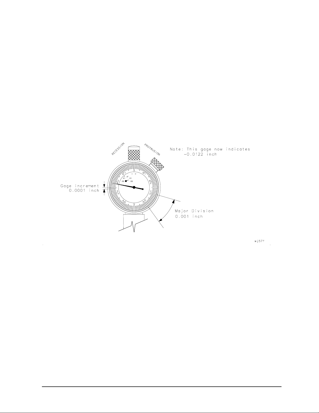
The gage dial is divided into increments of 0.0001 inch and major divisions of 0.001
inch (see Figure 3-2). For each revolution of the large dial, the smaller dial indicates a
change of 0.01 inch. Use the small dial as the indicator of multiples of 0.01 inch. In
most connector measuring applications, this value will be zero.
When making a measurement, the gage dial indicator will travel in one of two
directions. If the center conductor is recessed from the zero reference plane, the
indicator will move counterclockwise to indicate the amount of recession, which is
read as a negative value. If the center conductor protrudes, the indicator will move
clockwise to indicate the amount of protrusion, which is read as a positive value.
Refer to “Pin Depth” on page 2-3 for definitions of protrusion and recession.
Figure 3-2 Reading the Connector Gage
85050C 3-7
Page 28

Use, Maintenance, and Care of the Devices
Gaging Connectors
Gaging Procedure
NOTE
Always hold a connector gage by the gage barrel, below the dial
indicator. This gives the best stability, and improves measurement
accuracy.
1. Select the proper gage for your connector. Refer to Table 6-1 on page 6-2 for gage
part number.
2. Inspect and clean the gage, gage master, and device to be gaged. Refer to “Visual
Inspection” on page 3-3 and “Cleaning Connectors” on page 3-4 of this chapter.
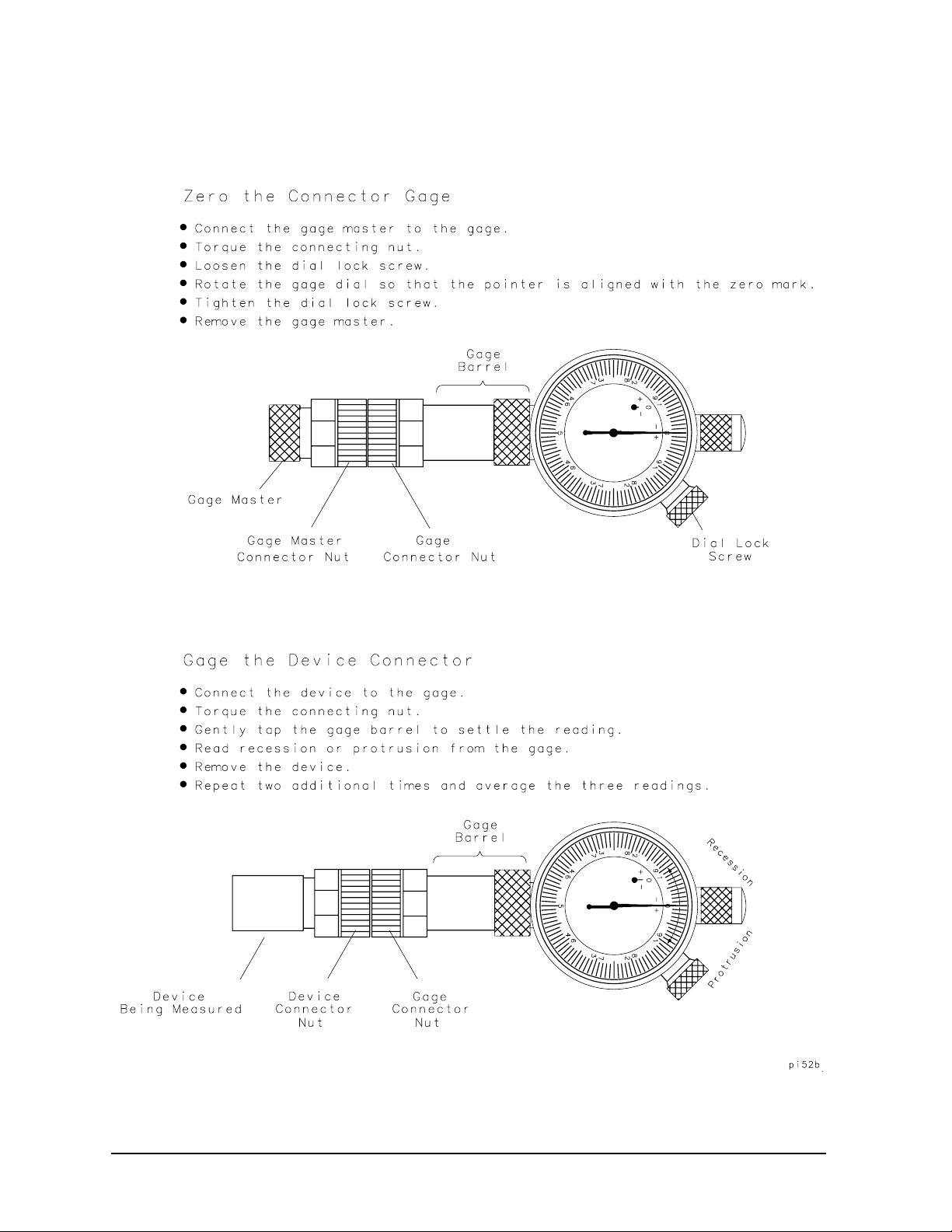
3. Zero the connector gage (refer to Figure 3-3):
a. While holding the gage by the barrel, and without turning the gage or the
device, connect the gage master to the gage. Refer to “Connections” on
page 3-13 for more information. Connect the nut finger tight. Do not
overtighten.
b. Using an open-end wrench to keep the gage from rotating, use the torque
wrench recommended for use with the kit to tighten the gage master connector
nut to the specified torque. Refer to “Final Connection Using a Torque Wrench”
on page 3-13 for more information.
c. The gage pointer should line up exactly with the zero mark on the gage. If not,
loosen the dial lock screw on the gage and rotate the gage dial so that the
pointer is aligned with the zero mark.
d. Tighten the dial lock screw and remove the gage master.
e. Attach and torque the gage master to the gage once again to verify that the
setting is repeatable. Remove the gage master.
4. Gage the device connector (refer to Figure 3-3):
a. If gaging one of the 50Ω loads in the kit, use a collet extractor tool to remove
the center conductor collet from the device connector to be gaged. Refer to
Table 6-1 on page 6-2 for the part number of this extractor tool. Refer to Figure
2-1 on page 2-4 for an illustration of the 7 mm connector and the location of the
center conductor collet.
b. While holding the gage by the barrel, and without turning the gage or the
device, connect the gage master to the device. Refer to “Connections” on
page 3-13 for more information. Connect the nut finger-tight. Do not
overtighten.
c. Using an open-end wrench to keep the gage from rotating, use the torque
wrench recommended for use with the kit to tighten the device connector nut
to the specified torque. Refer to “Final Connection Using a Torque Wrench” on
page 3-13 for more information.
3-8 85050C
Page 29

Use, Maintenance, and Care of the Devices
Gaging Connectors
d. Gently tap the barrel of the gage with your finger to settle the gage reading.
e. Read the gage indicator dial. If the needle has moved clockwise, the center conductor
is protruding by and amount indicated by the black numbers. If the needle has
moved counterclockwise, the center conductor is recessed by an amount indicated by
the red numbers.
For maximum accuracy, measure the connector a minimum of three times and take
an average of the readings. After each measurement, rotate the gage a quarter-turn
to reduce measurement variations that result from the gage or the connector face not
being exactly perpendicular to the center axis.
f. Compare the average reading with the pin depth specifications listed in Table 2-2 on
page 2-5.
g. Remove the device from the gage and replace the center conductor collet.
85050C 3-9
Page 30
Use, Maintenance, and Care of the Devices
Gaging Connectors
Figure 3-3 Gaging 7 mm Connectors
3-10 85050C
Page 31
Use, Maintenance, and Care of the Devices
Gaging Connectors
Gaging the Airline
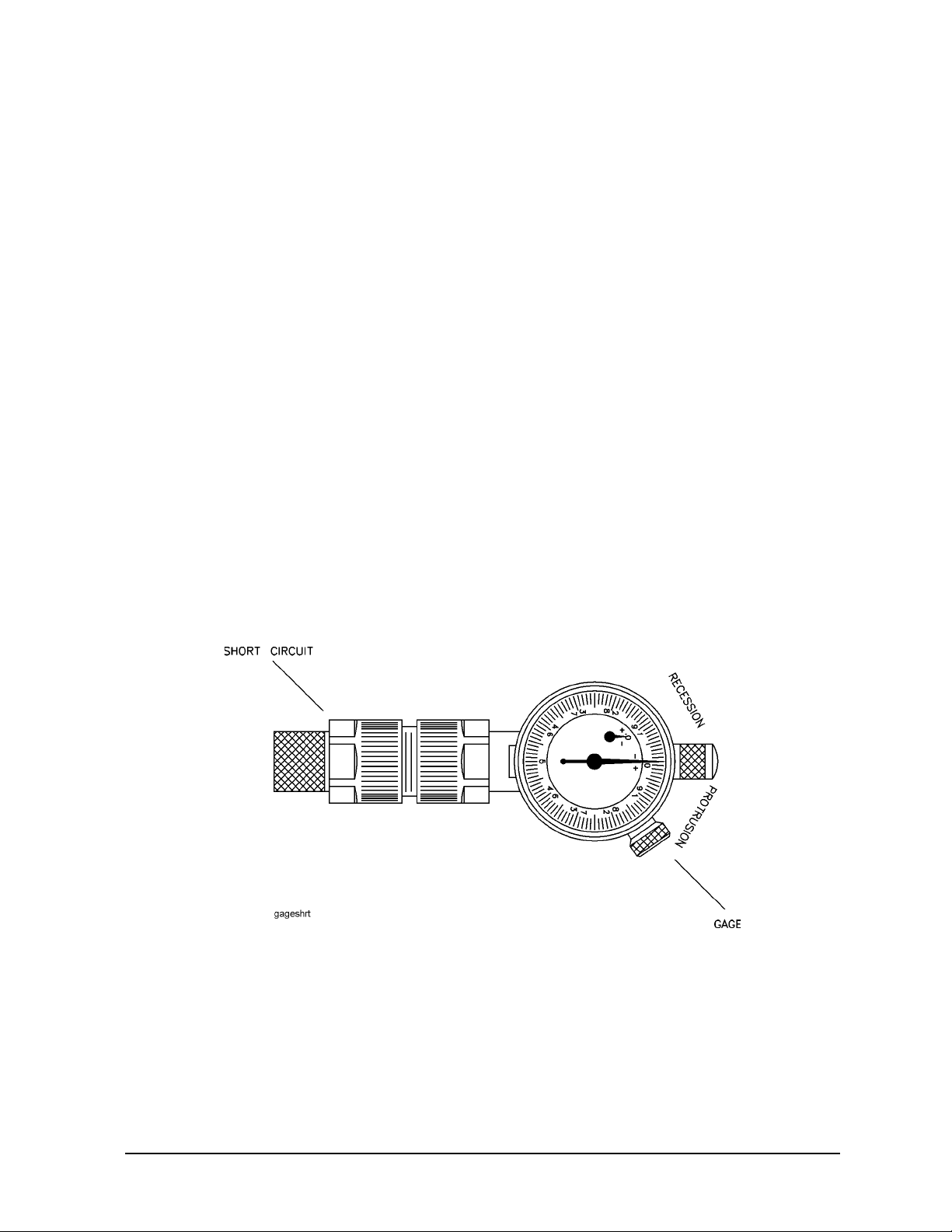
The airline center and outer conductor in this kit are measured and matched at the factory
using special fixtures and gages. Use the following procedure to verify the length
difference specification between the center and outer conductor.
1. Attach the short circuit with threaded center conductor to the gage. Torque the
connection to 136 N-cm, (12 in-lb). Refer to Figure 3-4.
2. Adjust the dial on the gage to read flush (0.000) when the short circuit is connected.
3. Remove the short circuit from the gage.
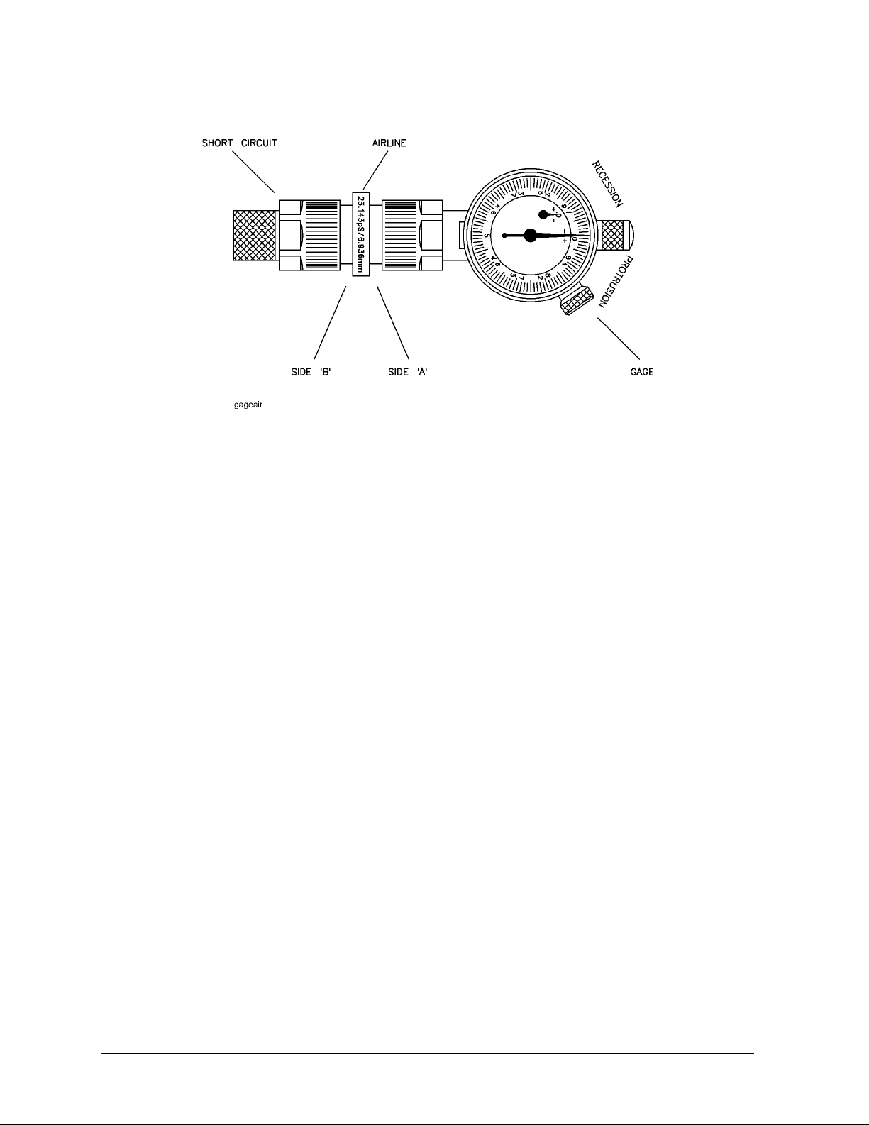
4. Attach the center conductor of the airline to the threaded short circuit termination.
Finger tighten the connection. Refer to Figure 3-5 on page 3-12.
5. Attach the gage to the other end of the airline. Turn the nut on the gage, do not rotate
the gage. Hand tighten the connections.
6. Torque the airline to short circuit connection and the airline-to-gage connection to 136
N-cm (12 in-lb). Set the assembly down to let the temperature stabilize for five minutes.
7. The reading on the gage should be within the given tolerance band of the dimension
measured 0.00025 inch;
gage accuracy, and
minor divisions).
± 0.0001 inch for factory uncertainties, ± 0.0001 inch for your
± 0.00005 inch for the mechanical tolerances of the airline (≤2.5
Reverse the above procedure to remove the gage and short circuit from the airline.
Figure 3-4 Gaging the Short Circuit
85050C 3-11
Page 32
Use, Maintenance, and Care of the Devices
Gaging Connectors
Figure 3-5 Gaging the Airline
3-12 85050C
Page 33

Use, Maintenance, and Care of the Devices
Connections
Connections
Good connections require a skilled operator. The most common cause of measurement error
is bad connections. The following procedures illustrate how to make good connections.
How to Make a Connection
Preliminary Connection
1. Ground yourself and all devices. Wear a grounded wrist strap and work on a grounded,
conductive table mat. Refer to “Electrostatic Discharge” on page 3-2 for ESD
precautions.
2. Visually inspect the connectors. Refer to “Visual Inspection” on page 3-3.
3. If necessary, clean the connectors. Refer to “Cleaning Connectors” on page 3-4.
4. Use a connector gage to verify that all center conductors are within the pin depth
specifications in Table 2-2 on page 2-5. Refer to “Gaging Connectors” on page 3-6.
5. Fully extend the connector sleeve on one of the connectors. Spin its knurled connector
nut to make sure the threads are fully extended. Fully retract the sleeve on the other
connector. The extended sleeve creates a cylinder into which the other connector fits.
If one of the connectors is fixed (such as on a test port), fully extend that connector
sleeve and fully retract the sleeve on the moveable connector.
6. Carefully align the connectors. As you make the actual connection, be sure the
connectors align perfectly.
7. Push the connectors straight together. Do not twist or screw the connectors together.
8. Engage the connector nut (of the connector with the retracted sleeve) over the threads
of the other connector (the connector with the extended sleeve). Turn only the connector
nut. Let the connector nut pull the two connectors straight together.
9. Do not overtighten this connection. A connection in which the outer conductors make
gentle contact at all points on both mating surfaces is sufficient. Very light finger
pressure is enough to accomplish this.
10.Make sure the connectors are properly supported. Relieve any side pressure on the
connection from long or heavy devices or cables.
Final Connection Using a Torque Wrench
Use a torque wrench to make a final connection. Table 3-1 provides information about the
torque wrench recommended for use with the calibration kit. A torque wrench is included
in the calibration kit. Refer to Table 6-1 on page 6-2 for replacement part number and
ordering information.
85050C 3-13
Page 34
Use, Maintenance, and Care of the Devices
Connections
Table 3-1 Torque Wrench Information
Connector Type Torque Setting Torque Tolerance
7 mm 136 N-cm (12 in-lb) ± 13.6 N-cm (± 1.2 in-lb)
Using a torque wrench guarantees that the connection is not too tight, preventing possible
connector damage. It also guarantees that all connections are equally tight each time.
Prevent the rotation of anything other than the connector nut that you are tightening. It
may be possible to do this by hand if one of the connectors is fixed (as on a test port).
However, it is recommended that you use an open-end wrench to keep the body of the
device from turning.
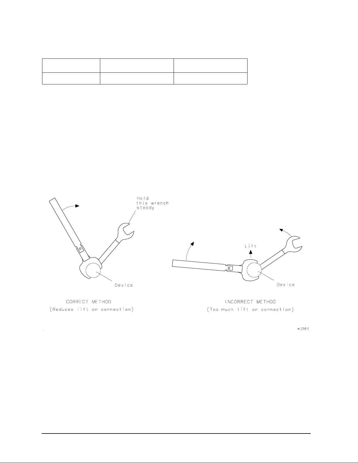
1. Position both wrenches within 90 degrees of each other before applying force. See
Figure 3-6. Wrenches opposing each other (greater than 90 degrees apart) will cause a
lifting action which can misalign and stress the connections of the devices involved.
This is especially true when several devices are connected together.
Figure 3-6 Wrench Positions
3-14 85050C
Page 35
Use, Maintenance, and Care of the Devices
Connections
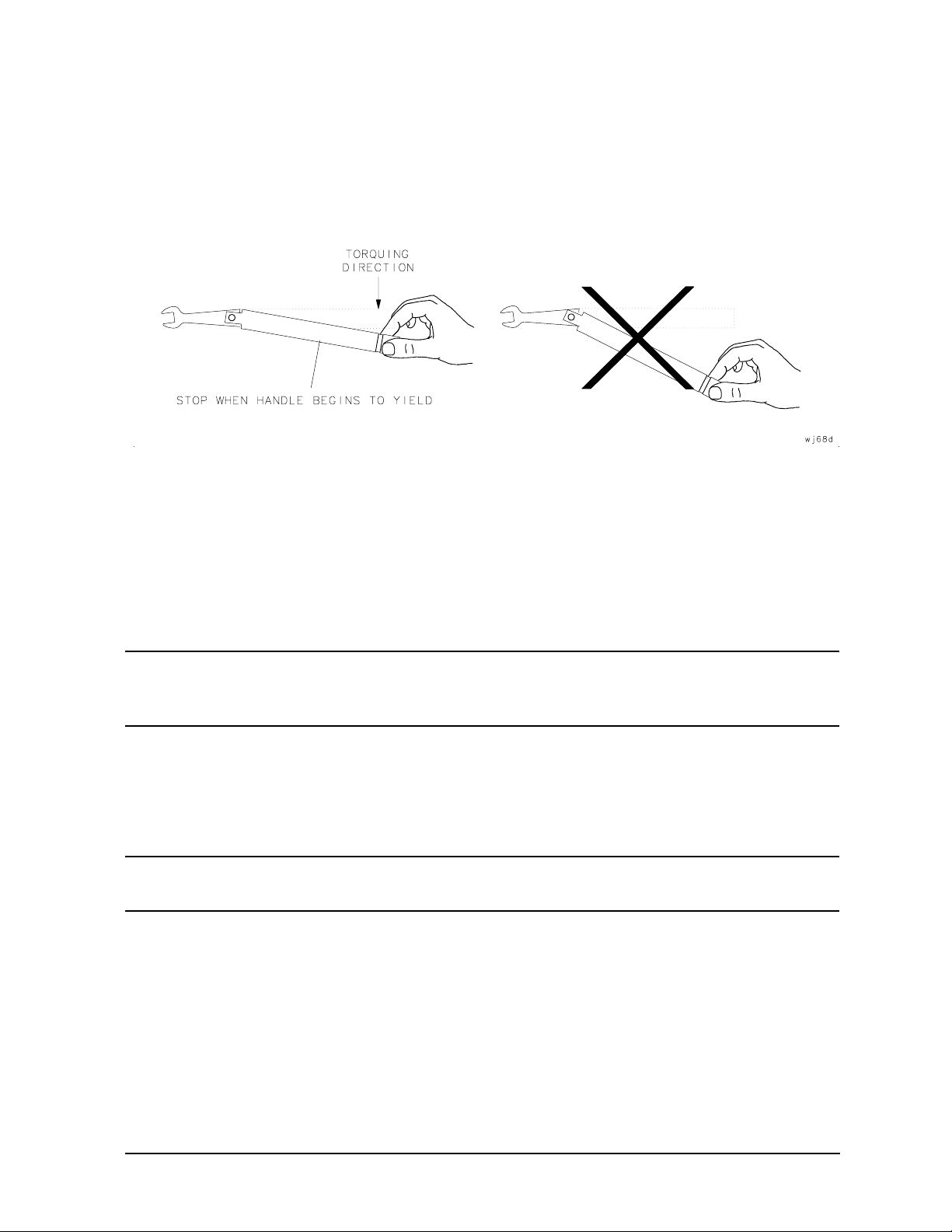
2. Hold the torque wrench lightly, at the end of the handle only (beyond the groove). See
Figure 3-7.
Figure 3-7 Using the Torque Wrench
3. Apply downward force perpendicular to the wrench handle. This applies torque to the
connection through the wrench.
Do not hold the wrench so tightly that you push the handle straight down along its
length rather than pivoting it, otherwise, you apply an unknown amount of torque.
4. Tighten the connection just to the torque wrench break point. The wrench handle gives
way at its internal pivot point. See Figure 3-7. Do not tighten the connection further.
CAUTION
You don’t have to fully break the handle of the torque wrench to reach the
specified torque; doing so can cause the handle to kick back and loosen the
connection. Any give at all in the handle is sufficient torque.
How to Separate a Connection
To avoid lateral (bending) force on the connector mating plane surfaces, always support the
devices and connections.
CAUTION
1. Use an open-end wrench to prevent the device body from turning.
2. Use the torque wrench to loosen the connecting nut.
Do not turn the device body. Only turn the connector nut. Damage to the
center conductor can occur if the device body is twisted.
3. Complete the separation by hand, turning only the connecting nut.
4. Pull the connectors straight apart without twisting, rocking, or bending either of the
connectors.
85050C 3-15
Page 36
Use, Maintenance, and Care of the Devices
Connections
CAUTION
Do not twist one connector out of the other (like removing a light bulb). Turn
the connector nut, not the device body. Major damage to the center conductor
can occur if the device body is twisted.
Using the TRL Adapter
This procedure provides step-by-step instructions for connecting the airline to a test port
or cable connector through the TRL adapter.
NOTE
1. Be sure the test port bias voltage is OFF.
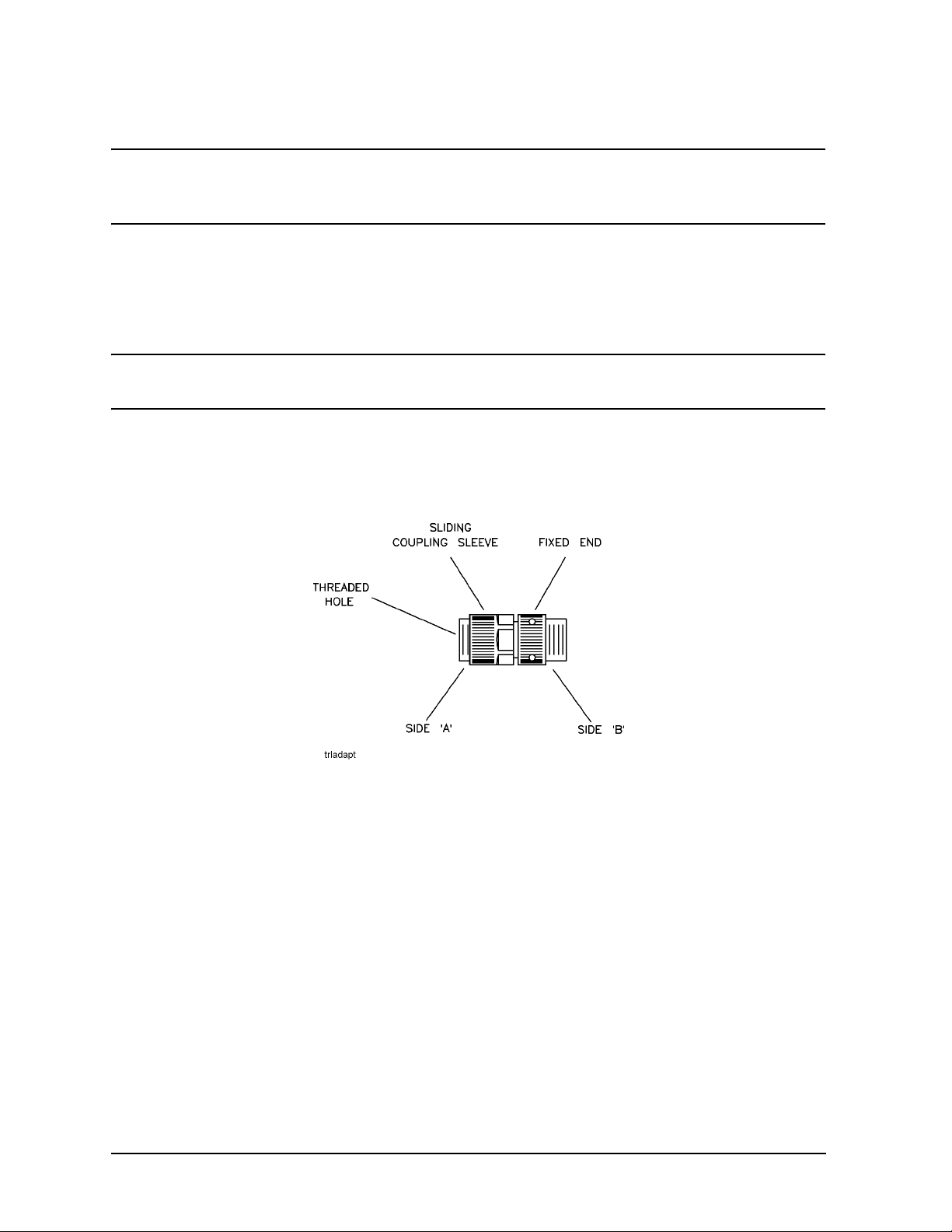
2. Note the orientation of the TRL adapter in Figure 3-8.
Figure 3-8 TRL Adapter
Always use good electrostatic discharge (ESD) practices. See “Electrostatic
Discharge” on page 3-2.
3-16 85050C
Page 37
Use, Maintenance, and Care of the Devices
Connections
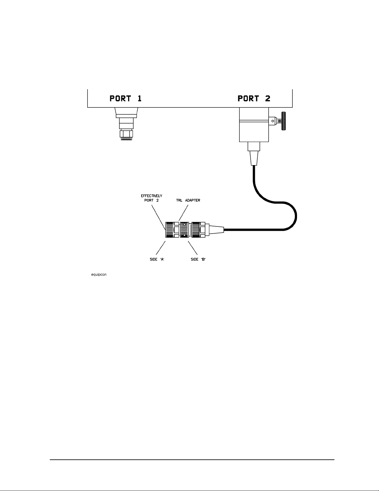
3. As shown in Figure 3-9, connect side “B” of the TRL adapter to the end of the cable on
port 2. Side “A” of the TRL adapter is now port 2.
Figure 3-9 Connecting the TRL Adapter
85050C 3-17
Page 38
Use, Maintenance, and Care of the Devices
Connections
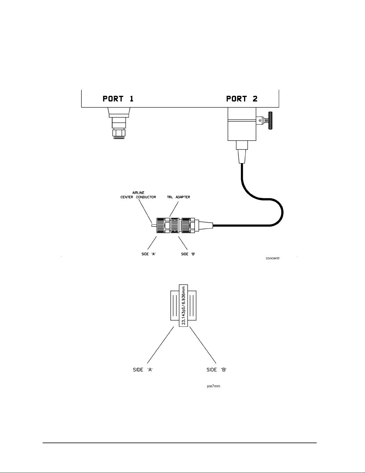
4. As shown in Figure 3-10, attach the 7 mm precision airline’s center conductor to side
“A” of the TRL adapter. Screw in the center conductor just until it stops moving (finger
tight).
Figure 3-10 Connecting the Airline Center Conductor
5. Note the orientation of the label on the airline outer conductor in Figure 3-11
Figure 3-11 7 mm Precision Airline
6. Position side “B” of the airline’s outer conductor over the center conductor and attach it
to the TRL adapter.
7. Connect side “A” of the airline to test port 1 (or to the end of the cable attached to the
port). Torque both connections to 136 N-cm (12 in-lb).
Reverse the above procedure to disconnect the airline from the cables.
3-18 85050C
Page 39

Pin/Collet Assemblies
Use, Maintenance, and Care of the Devices
Pin/Collet Assemblies
CAUTION
The pin/collet assemblies included in the 85050C calibration kit are for use
with the airlines in the 85051B verification kit. These pin/collet assemblies
must be used to assure valid verification data.
Do not use the 85051A verification kit to verify an 85050C calibration. The
mechanical-end detail of the airlines in these verification kits is not
compatible with the pin/collet assembly.
Using the Pin/Collet Assemblies
1. Withdraw the centering pin from the “B” ends of the 50 ohm airline center conductor
and the 25 ohm mismatch airline center conductor.
2. Insert a pin/collet assembly into the “B” end of each center conductor and perform a
verification as described in the appropriate verification kit manual or network analyzer
manual. The “B” end of the airline is always connected to the TRL adapter. The TRL
adapter does not have a collet of its own. Pin/collet assembly is necessary to assure a
good connection between the airline and the adapter.
Pin/collet assemblies can remain in the airline center conductors unless they are to be
installed and used in other 85051B verification airlines.
CAUTION
85051B verification kits with serial numbers of 2705A00163 and below,
purchased before September, 1987, should be returned to the Mountain View
Service Center, USA for recertification. Neglecting to do this may result in
irreparable mechanical damage to either the airline or to the attaching
connector.
Using the Centering Beads
The centering beads supplied are used when gaging the airlines contained in the 85051B
verification kit. Do not use the centering beads with any device in this 85050C 7 mm
precision calibration kit.
85050C 3-19
Page 40

Use, Maintenance, and Care of the Devices
Handling and Storage
Handling and Storage
• Install the protective end caps and store the calibration devices in the foam-lined
storage case when not in use.
• Never store connectors loose in a box, or in a desk or bench drawer. This is the most
common cause of connector damage during storage.
• Keep connectors clean.
• Do not touch mating plane surfaces. Natural skin oils and microscopic particles of dirt
are easily transferred to a connector interface and are very difficult to remove.
• Do not set connectors contact-end down on a hard surface. The plating and the mating
plane surfaces can be damaged if the interface comes in contact with any hard surface.
3-20 85050C
Page 41

4 Performance Verification
85050C 4-1
Page 42

Performance Verification
Introduction
Introduction
The performance of your calibration kit can only be verified by returning the kit to Agilent
Technologies for recertification. The equipment required to verify the specifications of the
devices in the kit has been specially manufactured and is not commercially available.
How Agilent Verifies the Devices in Your Kit
Agilent verifies the specifications of these devices as follows:
1. The residual microwave error terms of the test system are verified with precision
airlines and shorts that are directly traced to the National Institute of Standards and
Technology (NIST). The airline and short characteristics are developed from mechanical
measurements. The mechanical measurements and material properties are carefully
modeled to give very accurate electrical representation. The mechanical measurements
are then traced to NIST through various plug and ring gages and other mechanical
measurements.
2. Each calibration device is electrically tested on this system. For the initial (before sale)
testing of the calibration devices, Agilent includes the test measurement uncertainty as
a guardband to guarantee each device meets the published specification. For
recertifications (after sale), no guardband is used and the measured data is compared
directly with the specification to determine the pass or fail status. The measurement
uncertainty for each device is, however, recorded in the calibration report that
accompanies recertified kits.
These two steps establish a traceable link to NIST for Agilent to the extent allowed by the
institute’s calibration facility. The specifications data provided for the devices in the kit is
traceable to NIST through Agilent Technologies.
4-2 85050C
Page 43

Performance Verification
Recertification
Recertification
The following will be provided with a recertified kit:
• a new calibration sticker affixed to the case
• a certificate of calibration
• a calibration report for each device in the kit listing measured values, specifications,
and uncertainties
NOTE
Agilent Technologies offers a Standard calibration for the recertification of the kit. For
more information, contact Agilent Technologies. Refer to “Contacting Agilent” on page 5-4
for a list of offices.
A list of NIST traceable numbers may be purchased upon request to be
included in the calibration report.
How Often to Recertify
The suggested initial interval for recertification is 12 months or sooner. The actual need for
recertification depends on the use of the kit. After reviewing the results of the initial
recertification, you may establish a different recertification interval that reflects the usage
and wear of the kit.
NOTE
The recertification interval should begin on the date the kit is first used after
the recertification date.
Where to Send a Kit for Recertification
See “Contacting Agilent” on page 5-4 for information on where to send your kit for
recertification. Refer to “Returning a Kit or Device to Agilent” on page 5-3 for details on
sending your kit.
85050C 4-3
Page 44

Performance Verification
Recertification
4-4 85050C
Page 45

5 Troubleshooting
85050C 5-1
Page 46
Troubleshooting
Troubleshooting Process
Troubleshooting Process
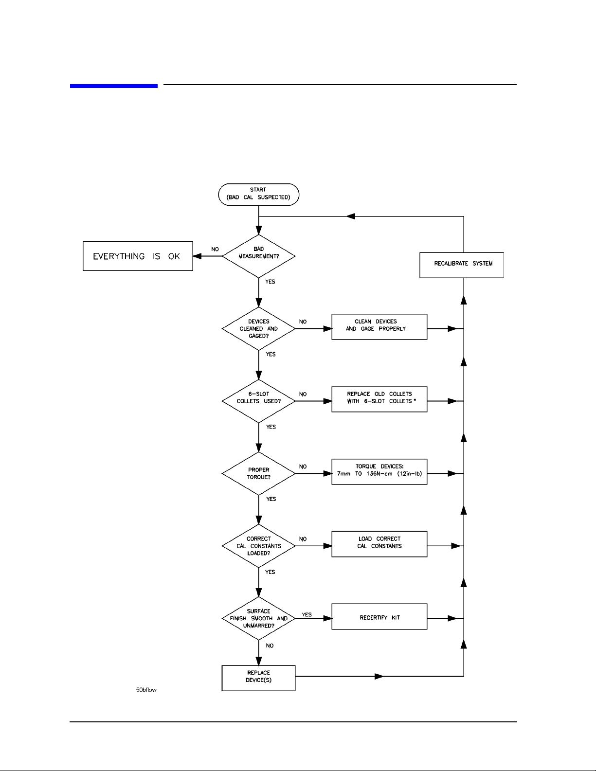
If you suspect a bad calibration, or if your network analyzer does not pass performance
verification, follow the steps in Figure 5-1.
Figure 5-1 Troubleshooting Flowchart
5-2 85050C
Page 47

Troubleshooting
Where to Look for More Information
Where to Look for More Information
This manual contains limited information about network analyzer system operation. For
detailed information on using a VNA, ENA or PNA series network analyzer, refer to the
appropriate user guide or online Help.
• To view the ENA or PNA online Help, press the Help key on the front panel of the
network analyzer.
• To view an online VNA user guide, use the following steps:
1. Go to www.agilent.com.
2. Enter your VNA model number (Ex: 8753ES) in the Search box and click Search.
3. Under the heading Manuals & Guides, click on the title/hyperlink for the
document PDF you want to view.
If you need additional information, see “Contacting Agilent” on page 4.
Returning a Kit or Device to Agilent
If your kit or device requires service, contact Agilent Technologies for information on
where to send it. See “Contacting Agilent” on page 4. Include a service tag (located near
the end of this manual) on which you provide the following information:
• your company name and address
• a technical contact person within your company, and the person's complete telephone
number
• the model number and serial number of the kit
• the part number and serial number of each device
• the type of service required
•a detailed description of the problem and how the device was being used when the
problem occurred (such as calibration or measurement)
85050C 5-3
Page 48

Troubleshooting
Contacting Agilent
Contacting Agilent
Assistance with test and measurements needs and information on finding a local Agilent
office are available on the Web at:
www.agilent.com/find/assist
If you do not have access to the Internet, please contact your Agilent field engineer.
NOTE
In any correspondence or telephone conversation, refer to the Agilent product
by its model number and full serial number. With this information, the
Agilent representative can determine whether your product is still within its
warranty period.
5-4 85050C
Page 49

6 Replaceable Parts
85050C 6-1
Page 50

Replaceable Parts
Introduction
Introduction
Table 6-1 lists the replacement part numbers for the 85050C calibration kit.
Table 6-2 lists the replacement part numbers for items not included in the calibration kit
that are either required or recommended for successful operation of the kit.
To order a listed part, note the description, the part number, and the quantity desired.
Telephone or send your order to Agilent Technologies. See “Contacting Agilent” on
page 5-4.
Table 6-1 Replaceable Parts for the 85050C Calibration Kit
Description Qty Agilent Part Number
Calibration Devices (7 mm)
7 mm broadband load 1 85050-60006
7 mm lowband load 1 00909-60008
7 mm short (collet style) 1 85050-80009
7 mm short (threaded center conductor style) 1 85050-80008
TRL adapter 1 85050-60005
7 mm open 1 85050-80010
7 mm precision airline 1 85050-60003
Tools
3/4 in, 135 N-cm (12 in-lb) torque wrench 1 8710-1766
7 mm connector collet extractor tool 1 5060-0370
Miscellaneous Items
Pin/collet assembly 2 85050-60007
Center conductor collets 4 85050-20001
7 mm connector gage set
User’s and service guide 1 85050-90051
Calibration definitions disk (8510C) 1 85050-10006
Specifications and performance verification disk set (8510 series)
a
Calibration Kit Storage Case
1 85050-80012
b
1 08510-10033
Box 1 5180-8419
(top)
Foam
Foam (bottom) 1 85050-80034
a. Gage set includes gage, gage master, aligning pin, and two centering beads.
b. See the 8510C On-Site Service Manual for instructions on using the disk.
1 5181-5542
6-2 85050C
Page 51
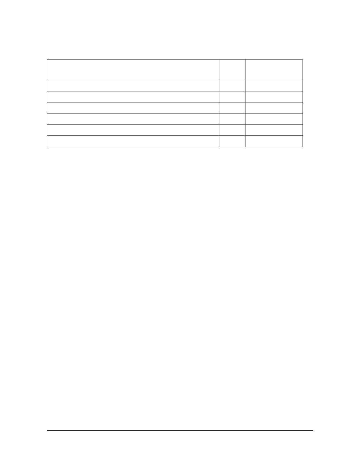
Table 6-2 Items Not Included in the Calibration Kit
Description Qty Agilent Part
Replaceable Parts
Introduction
Number
Anhydrous isopropyl alcohol (>92% pure)
Cleaning swabs 100 9301-1243
Grounding wrist strap 1 9300-1367
5 ft grounding cord for wrist strap 1 9300-0980
2 ft by 4 ft conductive table mat with 15 ft grounding wire 1 9300-0797
a
-- --
ESD heel strap 1 9300-1308
a. Agilent can no longer safely ship isopropyl alcohol, so customers should purchase it locally.
85050C 6-3
Page 52
Replaceable Parts
Introduction
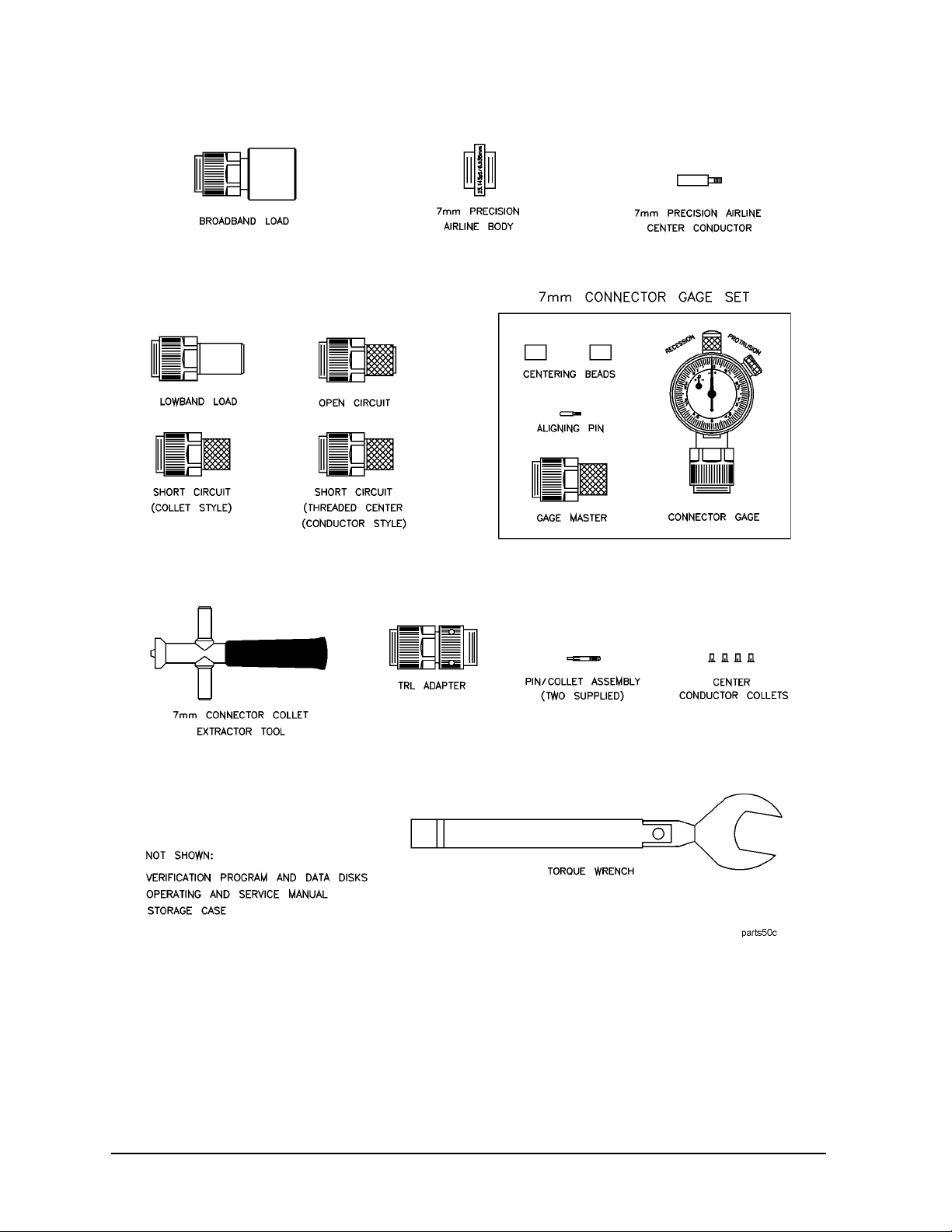
Figure 6-1 Replaceable Parts for the 85050C Calibration Kit
6-4 85050C
Page 53

A Standard Definitions
85050C A-1
Page 54

Standard Definitions
Class Assignments and Standard Definitions Values are Available on the Web
Class Assignments and Standard Definitions Values are
Available on the Web
Class assignments and standard definitions may change as more accurate model and
calibration methods are developed. You can download the most recent class assignments
and standard definitions from Agilent’s Calibration Kit Definitions Web page at
http://na.tm.agilent.com/pna/caldefs/stddefs.html.
For a detailed discussion of calibration kits, refer to the Agilent Application Note,
“Specifying Calibration Standards and Kits for Agilent Vector Network Analyzers.” This
application note covers calibration standard definitions, calibration kit content and its
structure requirements for Agilent vector network analyzers. It also provides some
examples of how to set up a new calibration kit and how to modify an existing calibration
kit definition file. To download a free copy, go to www.agilent.com and enter literature
number 5989-4840EN in the Search window.
A-2 85050C
Page 55

Index
A
adapter, TRL
adapters
specifications
Agilent Technologies
application note
contacting, 5-3, 5-4
agreements
customer assistance
maintenance, -iii
airline
mechanical dimensions, 2-6
precision, 1-3, 2-5
alcohol
isopropyl
as cleaning solvent
precautions for use of, 3-4
assemblies, pin/collet, 3-19
assistance
customer
who to contact, -iii
B
beads, centering
broadband loads, 1-3
part numbers, 6-2
specifications, 2-7
C
cal kit
contents
history, 1-5
verifying, 4-2
calibration
bad, 5-2
certificate of, 4-3
constants, See calibration definitions
definitions
8510-series, disk, part number
entering, 1-3
permanently stored, 1-3
frequency, 1-6
report, 4-3
temperature, 2-2
when to perform, 1-6
calibration kit
Agilent Application Note
contents, 1-2
drawing of, 6-4
history, 1-5
modifying definition files, A-2
overview, 1-2
performance
how Agilent verifies
center conductor
protrusion, 3-7
recession, 3-7
centering beads, using, 3-19
certificate of calibration, 4-3
, 3-16
, 2-7
, A-2
, -iii
, 3-4
, -iii
, 3-19
, 1-2
, A-2
, 4-2
, 6-2
certification
of device specifications
characteristics
mechanical
class assignments
downloading from Agilent Web site
cleaning connectors, 3-4
cleaning supplies, 1-3
compressed air
for cleaning
connections, 3-2, 3-13
ESD protection, 3-2, 3-13
final, 3-13
preliminary, 3-13
separating, 3-15
using torque wrench, 3-13
connector
cleaning, 3-4
damage, 3-3
defects, 3-3
gage
accuracy
dial, 3-7
handling, 3-8
reading, 3-7
use of, 3-6
zeroing, 3-8
gaging, 3-6
when to do, 3-6
male, 3-8
mating plane surfaces
cleaning
threads
cleaning
inspecting, 3-3
visual inspection, 3-3
wear, 3-3
affect on electrical performance, 3-3
constants, calibration, See calibration definitions
contacting Agilent Technologies
contents
calibration kit, 1-2
drawing of, 6-4
incomplete
what to do
D
damage
caused by electrostatic discharge
device, 3-3
inspecting for, 3-3
to connectors, 3-3
data
recertification, 4-3
defective connectors, 3-3
definitions
calibration, 1-3
deviation from nominal phase, 2-7
device
cleaning
, 2-3
, 3-4
, 3-6
, 3-5
, 3-4
, 1-4
, 3-4
, 2-7
, A-2
, 5-3
, 3-2
Index-1
Page 56

Index
connecting
damage, 3-3
disconnecting, 3-15
handling, 3-20
maintenance, 1-5
performance
verifying
specifications, 2-7
certification of, 2-7
electrical, 2-7
traceability, 4-2, 4-3
storage, 3-20
temperature, 2-2
visual inspection, 3-3
dial
connector gage, 3-7
disconnections, 3-15
disk
calibration definitions
part number
specifications and performance
part number
documentation, part number, 6-2
downloading class assignments & std definitions
from the Web, A-2
E
electrical characteristics
effects of temperature
electrical specifications, 2-7
electrostatic discharge, See ESD
environmental
regulations
requirements, 2-2
specifications, 2-2
equipment required, 1-3
ESD, 3-2
protection, 3-2
F
flowchart, troubleshooting
frequency of calibration, 1-6
frequency specifications, 2-7
G
gage
connector
dial, 3-7
handling, 3-8
reading, 3-7
zeroing, 3-8
gaging
connectors
when to do, 3-6
male connectors, 3-8
to determine pin depth, 3-6
general information, 1-1
, 3-13
, 4-2
, 6-2
, 6-2
, 2-2
, 3-4
, 5-2
, 1-3
, 3-6
H
handling
how often to calibrate, 1-6
humidity specifications, 2-2
I
incoming inspection
information, troubleshooting, 5-3
inspection
damage
defects, 3-3
incoming, 1-4
mating plane surfaces, 3-3
visual, 3-3
isopropyl alcohol
as cleaning solvent
precautions for use of, 3-4
K
kit
contents
overview, 1-2
L
limits
pin depth
loads
broadband, 1-3
M
maintenance
agreements, -iii
of devices, 1-5
preventive, 1-5
making connections, 3-13
ESD protection, 3-2, 3-13
precautions, 3-13
manual
part number, 6-2
printing, -iii
mating plane surfaces
cleaning
connector, 3-5
inspection of, 3-3
mechanical characteristics, 2-3
affect on electrical performance, 2-3
verifying, 3-6
mechanical dimensions, airline, 2-6
modifying calibration kit definition files, A-2
N
National Institute of Standards and Technology
nitrogen, for cleaning, 3-4
numbers
replaceable parts, 6-2, 6-3
, 3-20
, 3-3
, 1-2, 6-4
drawing of, 6-4
, 2-5
part numbers, 6-2
, 3-2
, 3-5
(NIST)
, 2-7, 4-2
, 1-4
, 3-4
Index-2
Page 57

Index
, 1-4
serial
O
observed limits
pin depth
offset opens and shorts, 1-3
part numbers, 6-2
specifications, 2-7
open-end wrench, 1-2, 3-15
part number, 6-2
opens, 1-3
part numbers, 6-2
specifications, 2-7
ordering parts, 6-2, 6-3
P
part numbers, 6-2
of items in kit, 6-2
of items not in kit, 6-3
parts
included in kit, 1-2, 6-2
not included in kit, 6-2, 6-3
ordering, 6-2
replaceable, 6-2
performance
and specifications disk
part number
performance verification
failure, 5-2
permanently stored calibration definitions, 1-3
pin depth, 2-3
affect on electrical performance, 2-4
gaging to determine, 3-6
observed limits, 2-5, 3-6
protrusion, 2-3
recession, 2-3
typical values, 2-5
pin/collet assemblies, using, 3-19
precision airline, 1-3, 2-5
preventive maintenance, 1-5
procedure for using the pin/collet assemblies, 3-19
procedure for using the TRL adapter, 3-16
procedures
cleaning
protrusion
center conductor
pin depth, 2-3
R
reading connector gage
recertification
how to order
interval, 4-3
locations, 4-3
services included, 4-3
recession
center conductor
pin depth, 2-3
regulations
environmental
, 2-5
, 6-2
, 3-4
, 3-7
, 3-7
, 4-3
, 3-7
, 2-2, 3-4
replaceable parts, 6-2, 6-3
drawing of, 6-4
report, calibration, 4-3
requirements
environmental, 2-2
return kit or device to Agilent, 1-4, 5-3
return loss, specifications, 2-7
S
separating connections
serial numbers, 1-4
devices, 1-4
recording, 1-4
service, 5-3
service tag, 4-3, 5-3
shorts, 1-3
part numbers, 6-2
specifications, 2-7
specifications, 2-2
adapters, 2-7
and performance disk
part number
broadband loads, 2-7
certification of, 2-7
deviation from nominal phase, 2-7
device, 2-7
electrical, 2-7
environmental, 2-2
frequency, 2-7
humidity, 2-2
offset opens and shorts, 2-7
return loss, 2-7
sliding loads, 2-7
temperature, 2-2
torque wrench, 3-13
traceability, 4-2, 4-3
standard definitions
downloading from Agilent Web site
standards
international
National Institute of Standards and Technology
(NIST)
static
discharge
electricity, 3-2
storage, 3-20
supplies
cleaning
swabs
cleaning
T
tag
service
temperature
affect on electrical performance
calibration, 2-2
cautions about, 2-2
changes in, 2-2
device, 2-2
, 4-3, 5-3
, 6-2
, 2-7
, 2-7, 4-2
, 3-2
, 1-3
, 3-4
, 3-15
, A-2
, 2-2
Index-3
Page 58

Index
error-corrected
measurement, 2-2
specifications, 2-2
operating, 2-2
storage, 2-2
verification and measurement, 2-2
test data, 4-3
threads
connector
cleaning
inspecting, 3-3
torque wrench, 1-3
specifications, 3-13
traceability
of device specifications
TRL adapter, using, 3-16
troubleshooting, flowchart, 5-2
U
user’s and service guide
part number
using the centering beads, 3-19
using the pin/collet assemblies, 3-19
using the TRL adapter, 3-16
V
verification
performance
temperature, 2-2
visual inspection, 3-3
, 2-2
, 3-4
, 4-2, 4-3
, 6-2
, 4-3
W
wear
connector
affect on electrical performance, 3-3
when to calibrate, 1-6
wrench
open-end, 1-3, 3-14, 3-15
proper positioning of, 3-14
torque, 1-3, 3-13, 3-14, 3-15
precautions for use of, 3-15
proper use of, 3-15
Z
zeroing
connector gage
, 3-3
, 3-8
Index-4
 Loading...